- Manuals
- Brands
- MSI Manuals
- Motherboard
- Z170A KRAIT GAMING
- User manual
-
Contents
-
Table of Contents
-
Troubleshooting
-
Bookmarks
Quick Links
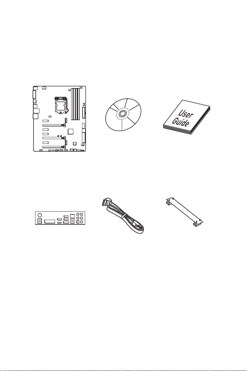
Unpacking
Thank you for buying the MSI
motherboard. Check to make sure your motherboard box contains the following items.
If something is missing, contact your dealer as soon as possible.
Motherboard
I/O Shield
Z170A KRAIT GAMING/ Z170 KRAIT GAMING
®
Drivers & Utilities
Disc
SATA Cable
Motherboard User
Guide
SLI Bridge
Connector
Unpacking
1
Related Manuals for MSI Z170A KRAIT GAMING
Summary of Contents for MSI Z170A KRAIT GAMING
-
Page 1: Unpacking
Unpacking Thank you for buying the MSI Z170A KRAIT GAMING/ Z170 KRAIT GAMING ® motherboard. Check to make sure your motherboard box contains the following items. If something is missing, contact your dealer as soon as possible. Drivers & Utilities…
-
Page 2: Safety Information
Safety Information ● The components included in this package are prone to damage from electrostatic discharge (ESD). Please adhere to the following instructions to ensure successful computer assembly. ● Ensure that all components are securely connected. Loose connections may cause the computer to not recognize a component or fail to start.
-
Page 3: Quick Start
Quick Start Preparing Tools and Components Intel LGA 1151 CPU ® CPU Fan Thermal Paste DDR4 Memory Power Supply Unit Chassis SATA Hard Disk Drive Graphics Card SATA DVD Drive A Package of Screws Phillips Screwdriver Quick Start…
-
Page 4: Installing A Processor
Installing a Processor http://youtu.be/bf5La099urI Quick Start…
-
Page 5: Installing Ddr4 Memory
Installing DDR4 memory http://youtu.be/T03aDrJPyQs Quick Start…
-
Page 6: Connecting The Front Panel Header
Connecting the Front Panel Header http://youtu.be/DPELIdVNZUI HDD LED + Power LED + HDD LED — Power LED — Reset Switch Power Switch Reset Switch Power Switch JFP1 Reserved No Pin JFP1 HDD LED — HDD LED HDD LED + POWER LED — POWER LED POWER LED + Quick Start…
-
Page 7: Installing The Motherboard
Installing the Motherboard Quick Start…
-
Page 8: Installing Sata Drives
Installing SATA Drives http://youtu.be/RZsMpqxythc Quick Start…
-
Page 9: Installing A Graphics Card
Installing a Graphics Card http://youtu.be/mG0GZpr9w_A Quick Start…
-
Page 10: Connecting Peripheral Devices
Connecting Peripheral Devices Quick Start…
-
Page 11: Connecting The Power Connectors
Connecting the Power Connectors http://youtu.be/gkDYyR_83I4 JPWR1 JPWR2 Quick Start…
-
Page 12: Power On
Power On Quick Start…
-
Page 13: Table Of Contents
Connecting the Power Connectors …………..11 Power On ………………….12 Specifications ………………….15 Block Diagram ………………….20 Z170A KRAIT GAMING ………………20 Z170 KRAIT GAMING ………………21 Rear I/O Panel ………………….22 LAN Port LED Status Table …………….22 Audio Ports Configuration ……………… 22 Realtek HD Audio Manager …………….
-
Page 14
JBAT1: Clear CMOS (Reset BIOS) Jumper …………38 EZ Debug LED: Debug LED indicators …………38 BIOS Setup ………………….39 Entering BIOS Setup ………………39 Resetting BIOS ………………..40 Updating BIOS ………………..40 EZ Mode ………………….41 Advanced Mode ………………..43 SETTINGS …………………. -
Page 15: Specifications
Specifications Supports 6th Gen Intel Core i3/i5/i7 processors, and Intel ® ™ ® Pentium and Celeron processors for Socket LGA1151 ® ® Chipset Intel Z170 Express Chipset ® ● 4x DDR4 memory slots, support up to 64GB ▶ Supports DDR4 3600(OC)/ 3200(OC)/ 3000(OC)/ 2800(OC)/ 2600(OC)/ 2400/ 2133 MHz Memory ●…
-
Page 16
2x USB 2.0 ports (Z170A KRAIT GAMING) ● 4x USB 2.0 ports (Z170 KRAIT GAMING) ● 1x DVI-D port ● 2x USB 3.1 Gen2 ports (Z170A KRAIT GAMING) Back Panel Connectors ● 4x USB 3.1 Gen1 ports ● 1x HDMI port ™… -
Page 17
Continued from previous page ● 1x 24-pin ATX main power connector ● 1x 8-pin ATX 12V power connector ● 6x SATA 6Gb/s connectors (2 ports reserved for SATA Express port) ● 1x SATAe connector ● 2x USB 2.0 connectors (supports additional 4 USB 2.0 ports) ●… -
Page 18
▶ Golden Audio Connectors ● GAME BOOST ▶ Easy Overclocking ● GAMING LAN ▶ Intel I219-V Gigabit Ethernet ▶ MSI Network Manager Performance ▶ Electric Wave Surge GAMING Features ● GAMING APP ▶ System Mode Switching: OC/Gaming/Silent ▶ Gaming Hotkey ▶… -
Page 19
▶ 2-Way Nvidia SLI Support ▶ 3-Way AMD CrossFire Support Specification ● USB 3.1 Gen2 Ready (Z170A KRAIT GAMING) Highlights ▶ USB 3.1 Gen2 (10 Gb/s) Type-A Ready ● Turbo M.2 Ready ▶ PCIe 3.0 x4 (32 Gb/s) Support ▶… -
Page 20: Block Diagram
Block Diagram Z170A KRAIT GAMING HDMI DVI-D Dual Channel DDR4 Memory PCI Express DMI 3.0 PCIe x1 1 x SATA Express (2 x SATA 6Gb/s) PCIe x1 1 x M.2 PCIe x1 4 x SATA 6Gb/s PCI Bus Z170 6 x USB 3.1 Gen1…
-
Page 21: Z170 Krait Gaming
Z170 KRAIT GAMING HDMI DVI-D Dual Channel DDR4 Memory PCI Express DMI 3.0 PCIe x1 1 x SATA Express (2 x SATA 6Gb/s) PCIe x1 1 x M.2 PCIe x1 4 x SATA 6Gb/s PCI Bus Z170 6 x USB 3.1 Gen1 (5 Gbps) 8 x USB 2.0 LPC Bus…
-
Page 22: Rear I/O Panel
Rear I/O Panel USB 3.1 Gen1 Audio Ports USB 3.1 Gen2 (blue, PS/2 Z170A KRAIT GAMING) USB 2.0 (black, Z170 KRAIT GAMING) USB 2.0 DVI-D Optical S/PDIF-Out USB 3.1 Gen1 LAN Port LED Status Table Link/ Activity LED Speed LED…
-
Page 23: Realtek Hd Audio Manager
Realtek HD Audio Manager After installing the Realtek HD Audio driver, the Realtek HD Audio Manager icon will appear in the system tray. Double click on this icon to launch. Device Selection Advanced Settings Jack Status Application Enhancement Main Volume Connector Strings Profiles…
-
Page 24
Audio jacks to headphone and microphone diagram Audio jacks to stereo speakers diagram AUDIO INPUT Audio jacks to 7.1-channel speakers diagram AUDIO INPUT Rear Front Side Center/ Subwoofer Rear I/O Panel… -
Page 25: Overview Of Components
Overview of Components DIMM1 DIMM3 SYSFAN1 DIMM2 DIMM4 CPUFAN1 CPUFAN2 JPWR2 CPU Socket SYSFAN3 EZ Debug LED JPWR1 PCI_E1 JUSB3 PCI_E2 M2_1 PCI_E3 JBAT1 SATA6 PCI_E4 SATA5 PCI_E5 SATA3 PCI1 SATA4 JCI1 PCI_E6 JAUD1 SE1_21 SYSFAN2 JUSB1 JUSB2 JTBT1* JFP2 JTPM1 JFP1 * JTBT1 is used to connect a specific card.
-
Page 26
Component Contents Port Name Port Type Page CPUFAN1~2, SYSFAN1~3 Fan Connectors CPU Socket LGA1151 CPU Socket DIMM1~4 DIMM Slots EZ Debug LED Debug LED indicators JAUD1 Front Audio Connector JBAT1 Clear CMOS (Reset BIOS) Jumper JCI1 Chassis Intrusion Connector JFP1, JFP2 Front Panel Connectors JPWR1~2 Power Connectors… -
Page 27: Cpu Socket
Always unplug the power cord from the power outlet before installing or removing ● the CPU. Please retain the CPU protective cap after installing the processor. MSI will deal ● with Return Merchandise Authorization (RMA) requests if only the motherboard comes with the protective cap on the CPU socket.
-
Page 28: Dimm Slots
DIMM Slots DIMM1 DIMM3 Channel A Channel B DIMM2 DIMM4 Memory module installation recommendation DIMM4 DIMM4 DIMM3 DIMM2 DIMM2 DIMM2 DIMM1 Important Always insert memory modules in the DIMM2 slot first. ● ● Due to chipset resource usage, the available capacity of memory will be a little less than the amount of installed.
-
Page 29: Pci_E1~6, Pci1: Pcie/ Pci Expansion Slots
PCI_E1~6, PCI1: PCIe/ PCI Expansion Slots PCI_E1: PCIe 3.0 x1 slot PCI_E2: PCIe 3.0 x16 slot PCI_E3: PCIe 3.0 x1 slot PCI_E4: PCIe 3.0 x1 slot PCI_E5: PCIe 3.0 x8 slot PCI1: PCI slot PCI_E6: PCIe 3.0 x4 slot Multiple graphics cards installation recommendation Important For a single PCIe x16 expansion ●…
-
Page 30: Installing Sli Graphics Cards
Installing SLI graphics cards For power supply recommendations for SLI configurations, please refer to the user guide of your graphics card to make sure you meet all the system requirements. To install SLI graphics cards: Turn off your computer and disconnect the power cord, install two graphics cards into the PCI_E2 and PCI_E5 slots.
-
Page 31: Sata1~6: Sata 6Gb/S Connectors
SATA1~6: SATA 6Gb/s Connectors These connectors are SATA 6Gb/s interface ports. Each connector can connect to one SATA device. SATA6 SATA2 SATA5 SATA1 SATA3 SATA4 SE1_21: SATAe Connector This connector is SATAe (SATA Express) interface port. Each SATAe connector can be used with a single SATAe device or two legacy SATA devices.
-
Page 32: M2_1: M.2 Slots
M2_1: M.2 Slot Important ● SATA5~6 ports will be unavailable when installing the M.2 module in M.2 slot. ● Intel RST only supports PCIe M.2 SSD with UEFI ® ROM, does not support Legacy ROM. Video Demonstration Watch the video to learn how to Install M.2 module.
-
Page 33: Jpwr1~2: Power Connectors
JPWR1~2: Power Connectors These connectors allow you to connect an ATX power supply. JPWR2 Ground +12V Ground +12V Ground +12V Ground +12V +3.3V +3.3V +3.3V -12V Ground Ground PS-ON# Ground Ground Ground JPWR1 Ground Ground PWR OK 5VSB +12V +12V +3.3V Ground Important…
-
Page 34: Jfp1, Jfp2: Front Panel Connectors
JFP1, JFP2: Front Panel Connectors These connectors connect to the switches and LEDs on the front panel. JFP1 HDD LED + Power LED + HDD LED — Power LED — Reset Switch Power Switch Reset Switch Power Switch Reserved No Pin Speaker — Buzzer + JFP2…
-
Page 35: Jusb3: Usb 3.1 Gen1 Connector
JUSB3: USB 3.1 Gen1 Connector This connector allows you to connect USB 3.1 Gen1 ports on the front panel. Power USB2.0+ USB3_RX_DN USB2.0- USB3_RX_DP Ground Ground USB3_TX_C_DP USB3_TX_C_DN USB3_TX_C_DN USB3_TX_C_DP Ground Ground USB3_RX_DP USB2.0- USB3_RX_DN USB2.0+ Power Ground No Pin Important Note that the Power and Ground pins must be connected correctly to avoid possible damage.
-
Page 36: Cpufan1~2, Sysfan1~3: Fan Connectors
CPUFAN1~2, SYSFAN1~3: Fan Connectors Fan connectors can be classified as PWM (Pulse Width Modulation) Mode and Voltage Mode. PWM Mode fan connectors provide constant 12V output and adjust fan speed with speed control signal. Voltage Mode fan connectors control fan speed by changing voltage.
-
Page 37: Jci1: Chassis Intrusion Connector
JCI1: Chassis Intrusion Connector This connector allows you to connect the chassis intrusion switch cable. Normal Trigger the chassis intrusion event (default) Using chassis intrusion detector Connect the JCI1 connector to the chassis intrusion switch/ sensor on the chassis. Close the chassis cover. Go to BIOS >…
-
Page 38: Resetting Bios To Default Values
JBAT1: Clear CMOS (Reset BIOS) Jumper There is CMOS memory onboard that is external powered from a battery located on the motherboard to save system configuration data. If you want to clear the system configuration, set the jumpers to clear the CMOS memory. Keep Data Clear CMOS/ Reset BIOS…
-
Page 39: Bios Setup
Press Delete key, when the Press DEL key to enter Setup Menu, F11 to enter Boot Menu message appears on the screen during the boot process. Use MSI FAST BOOT application. Click on GO2BIOS button and choose OK. The ●…
-
Page 40: Resetting Bios
Updating BIOS Updating BIOS with M-FLASH Before updating: Please download the latest BIOS file that matches your motherboard model from MSI website. And then save the BIOS file into the USB flash drive. Updating BIOS: Press Del key to enter the BIOS Setup during POST.
-
Page 41: Ez Mode
EZ Mode At EZ mode, it provides the basic system information and allows you to configure the basic setting. To configure the advanced BIOS settings, please enter the Advanced Mode by pressing the Setup Mode switch or F7 function key. XMP switch Setup Mode switch Screenshot…
-
Page 42
● GAME BOOST toggle — click on it to toggle the GAME BOOST for OC. Important Please don’t make any changes in OC menu and don’t load defaults to keep the optimal performance and system stability after activating the GAME BOOST function. ●… -
Page 43: Advanced Mode
Advanced Mode Press Setup Mode switch or F7 function key can switch between EZ Mode and Advanced Mode in BIOS setup. XMP switch Setup Mode switch Screenshot Favorites Language System information GAME BOOST toggle Boot device priority bar BIOS menu BIOS menu selection selection…
-
Page 44: Settings
SETTINGS System Status ▶ System Date Sets the system date. Use tab key to switch between date elements. The format is <day> <month> <date> <year>. <day> Day of the week, from Sun to Sat, determined by BIOS. Read-only. <month> The month from Jan. through Dec. <date>…
-
Page 45
PEG X — Max Link Speed [Auto] ▶ Sets PCI Express protocol of PCIe x16 slots for matching different installed devices. [Auto] This item will be configured automatically by BIOS. [Gen1] Enables PCIe Gen1 support only. [Gen2] Enables PCIe Gen2 support only. [Gen3] Enables PCIe Gen3 support only. -
Page 46
Ipv6 PXE Support [Enabled] ▶ When “Enabled”, the system UEFI network stack will support Ipv6 protocol. This item will appear when “Network Stack” is enabled. [Enabled] Enables the Ipv6 PXE boot support. [Disabled] Disables the Ipv6 PXE boot support. ▶ SATA Mode [AHCI Mode] Sets the operation mode of the onboard SATA controller. -
Page 47
USB Controller [Enabled] ▶ Enables or disables all USB controller. ▶ XHCI Hand-off [Enabled] Enables or disables XHCI hand-off support for the operating system without XHCI hand-off feature. This item will appear when USB Controller is enabled. ▶ Legacy USB Support [Enabled] Sets Legacy USB function support. -
Page 48
MSI Fast Boot [Disabled] ▶ MSI Fast Boot is the fastest way to boot the system. It will disable more devices to speed up system boot time which is faster than the boot time of Fast Boot. [Enabled] Enables the MSI Fast Boot function to speed up booting time. And the following Fast Boot field will be disabled and fixed. -
Page 49
Wake Up Event By [BIOS] ▶ Selects the wake up event by BIOS or operating system. [BIOS] Activates the following items, set wake up events of these items. [OS] The wake up events will be defined by OS. ▶ Resume By RTC Alarm [Disabled] Disables or enables the system wake up by RTC Alarm. -
Page 50: Boot
Hot Key [Ctrl+Space] ▶ Selects a combination of keys as a hot key to wake the system. This item appears when you set the Resume From S3/S4/S5 by PS/2 Keyboard to Hot Key. Intel ( R ) Ethernet Connection I219-V ▶…
-
Page 51
User Password ▶ Sets User Password for system security. User has limited rights to change the BIOS items with user password. This item will be available when administrator password is set. After setting the user password, the state of this item will show “Installed”. ▶… -
Page 52: Save & Exit
Chassis Intrusion [Disabled] ▶ Enables or disables recording messages when the chassis is opened. This function is ready for the chassis equips a chassis intrusion switch. [Enabled] Once the chassis is opened, the system will record and issue a warning message. [Reset] Clear the warning message.
-
Page 53: Oc
Important ● Overclocking your PC manually is only recommended for advanced users. Overclocking is not guaranteed, and if done improperly, it could void your warranty ● or severely damage your hardware. ● If you are unfamiliar with overclocking, we advise you to use GAME BOOST function for easy overclocking.
-
Page 54
CPU Ratio Mode [Dynamic Mode]* ▶ Selects the CPU Ratio operating mode. This item will appear when you set the CPU ratio manually. [Fixed Mode] Fixes the CPU ratio. [Dynamic Mode] CPU ratio will be changed dynamically according to the CPU loading. -
Page 55
CPU Base Clock Apply Mode [Auto]* ▶ Sets the applying mode for adjusted CPU base clock. [Auto] This setting will be configured automatically by BIOS. [Next Boot] CPU will run the adjusted CPU base clock at next boot. [Immediate] CPU runs the adjusted CPU base clock immediately. [During Boot] CPU will run the adjusted CPU base clock during boot. -
Page 56
CPU Core/ GT Voltage Mode [Auto]* ▶ Selects the control mode for CPU Core/ GT voltages. [Auto] This setting will be configured automatically by BIOS. [Adaptive Mode] Sets the adaptive voltage automatically for optimizing the system performance. [Override Mode] Allows you to set the voltage manually. [Offset Mode] Allows you to set the offset voltage and select the voltage offset mode. -
Page 57
CPU Features ▶ Press <Enter> to enter the sub-menu. ▶ Hyper-Threading [Enabled] Intel Hyper-Threading technology treats the multi cores inside the processor as multi logical processors that can execute instructions simultaneously. In this way, the system performance is highly improved. This item appears when the installed CPU supports this technology. -
Page 58
Adjacent Cache Line Prefetch [Enabled] ▶ Enables or disables the CPU hardware prefetcher (MLC Spatial prefetcher). [Enabled] Enables adjacent cache line prefetching for reducing the cache latency time and tuning the performance to the specific application. [Disabled] Enables the requested cache line only. ▶… -
Page 59
Intel Turbo Boost [Enabled] ▶ Enables or disables the Intel Turbo Boost. This item is for Normal mode and ® appears when a CPU that support Turbo Boost is installed. [Enabled] Enables this function to boost CPU performance automatically over specification when system request the highest performance state. -
Page 60: M-Flash
M-FLASH provides the way to update BIOS with a USB flash drive. Please download the latest BIOS file that matches your motherboard model from MSI website, save the BIOS file into your USB flash drive. And then follow the steps below to update BIOS.
-
Page 61: Oc Profile
OC PROFILE ▶ Overclocking Profile 1/ 2/ 3/ 4/ 5/ 6 Overclocking Profile 1/ 2/ 3/ 4/ 5/ 6 management. Press <Enter> to enter the sub- menu. ▶ Set Name for Overclocking Profile 1/ 2/ 3/ 4/ 5/ 6 Name the current overclocking profile. ▶…
-
Page 62: Hardware Monitor
HARDWARE MONITOR Current Temperature & Speed information Fan control field Setting Buttons Voltage display ▶ Current Temperature & Speed information Shows the current CPU temperature, system temperature and fans’ speeds. ▶ Fan control field This motherboard provides a fan speed control feature call Smart Fan. Please check the Smart Fan Mode box to enable the Smart Fan.
-
Page 63: Software Description
Windows 7. Installing Drivers Start up your computer in Windows 7/ 8.1/ 10. ® Insert MSI Driver Disc into your optical drive. ® The installer will automatically appear and it will find and list all necessary drivers. Click Install button.
-
Page 64: Command Center
COMMAND CENTER COMMAND CENTER is an user-friendly software and exclusively developed by MSI, helping users to adjust system settings and monitor status under OS. With the help of COMMAND CENTER, making it possible to achieve easier and efficient monitoring process and adjustments than that under BIOS. In addition, the COMMAND CENTER can be a server for mobile remote control application.
-
Page 65
CPU Fan CPU Fan control panel provides Smart mode and Manual Mode. You can switch the control mode by clicking the Smart Mode and Manual Mode buttons on the top of the CPU Fan control panel. ● Manual Mode — allows you to manually control the CPU fan speed by percentage. -
Page 66
GAME BOOST GAME BOOST provides a specified CPU frequency for overclocking the CPU. Option Buttons — Advanced When click the Advanced button, The Voltage, Fan and DRAM icons will appear. ● Voltage — allows you to adjust advanced voltage values of CPU and chipset. ●… -
Page 67: Gadget Mode
Find the IP address on the SoftAP Management Setting area, and enter the IP address on your MSI COMMAND CENTER APP to link your system. ® Press Refresh on the MSI COMMAND CENTER APP to verify that monitoring ® and OC functions are working properly.
-
Page 68: Live Update 6
LIVE UPDATE 6 LIVE UPDATE 6 is an application for the MSI system to scan and download the latest ® drivers, BIOS and utilities. With LIVE UPDATE 6, you don’t need to search the drivers on websites, and don’t need to know the models of motherboard and graphics cards.
-
Page 69: Total Installer
Select the Live Update tab. Choose Automatic scan, system will automatically scan all the items and search for the latest update files. Or you can choose Manual scan and select the items you wish to scan. Click the Scan button at the bottom. It may take several moments to complete the process.
-
Page 70: Gaming App
GAMING APP GAMING APP is an application designed to quickly control your system for improving gaming performance. Setting Button Information Button Display Mode Button CPU Frequency GPU Frequency Gaming Function Full Speed GPU Fan Buttons Control Mode Buttons ● Setting Button — allows you to run GAMING APP when Windows starts. Information Button — shows the information of this application.
-
Page 71
OSD Setting Panel Use the OSD setting panel to specify information within on-screen display (OSD). ● Apply Button — allows you to accept selections. Software Description… -
Page 72
Login Keys — provides hotkey login function. ▶ ▶ MSI Smart Keys — allows you to define hotkeys for MSI Smart Keys. ● Hotkey Manager — allows you to create, edit and delete hotkeys. Current Hotkeys — shows all existing hotkeys. -
Page 73
Gaming Mouse Control Gaming Mouse Control provides mouse macro function. You can also use it to change DPI of your mouse. DPI Setting Delay Time Defalut Button Macro Hot Key DPI Hot Key Mouse Action Action List Test Area Edit Buttons Clear Button Load Button Save Button… -
Page 74: M-Cloud
M-CLOUD M-CLOUD is an application of MSI network sharing. It allows you to turn your computer into Wi-Fi AP. It can also transfer files between your MSI computers. Soft AP ON/OFF History Server Information Users & Permissions Server Local Directory…
-
Page 75
Setting up Soft AP (optional) The Soft AP function is only available for the motherboard with the built-in WiFi module. You can share your network connection to your smartphones, tablets and laptops with the Soft AP function. Important ● You must have an active network connection and an installed Wi-Fi moudle to enable Soft AP. -
Page 76
Managing User Accounts This section describes how to create/ remove a user account and configure individual access permissions. Click the Users & Permissions button and the Users & Permissions Management window will pop up. Click Add Account button create a new user account. Fill in user’s ID, password and Confirm Password fields. -
Page 77: Ramdisk
RAMDISK RAMDISK creates a virtual RAM drive using the available memory in your computer, the performance of the RAMDISK is faster than an SSD and hard drive. RAMDISK allows you to store any temporary information on it. Furthermore, using the RAMDISK will extend your SSD’s life by sparing it from excessive reading and writing.
-
Page 78: Gaming Lan Manager
GAMING LAN MANAGER GAMING LAN MANAGER is an utility for traffic shaping for the Windows 7/ 8.1/ 10. It can keep your internet fast during heavy upload/ download and improve your ping for online games. If your motherboard has a Wi-Fi module, GAMING LAN MANAGER provides virtual access point function for traffic shaping for your mobile devices.
-
Page 79
Speed Testing The speed testing is used to optimize bandwidth usage. To test the Upload and Down- load speed, please follow the steps below: Click the Network Test block in GAMING LAN MANAGER. Click Test Network Speed button. The test takes several minutes to test your network speed. -
Page 80: Intel ® Extreme Tuning Utility
Intel Extreme Tuning Utility ® Intel Extreme Tuning Utility (Intel XTU) is a simple overclocking software for you to ® tune, test and monitor your system. Tuning Controls Views Settings Help System Navigation Table System System Monitors Graphs ● Views Settings Help ▶…
-
Page 81: Raid Configuration
RAID Configuration Below are the different types of a RAID. RAID 0 breaks the data into blocks which are written to separate hard drives. Spreading the hard drive I/O load across independent channels greatly improves I/O performance. RAID 1 provides data redundancy by mirroring data between the hard drives and provides enhanced read performance.
-
Page 82
Creating RAID Volume Select option Create RAID Volume and press Enter key. The following screen appears. CREATE VOLUME MENU Name : Volume0 RAID Level : RAID1(Mirror) Disks : Select Disks Strip Size : N / A Capacity : XXX.X GB Sync : N / A Create Volume… -
Page 83: Delete Raid Volume
Delete RAID Volume Here you can delete the RAID volume, but please be noted that all data on RAID drives will be lost. Important If your system currently boots to RAID and you delete the RAID volume in the IRST Option ROM, your system will become unbootable.
-
Page 84: Degraded Raid Array
Important ● You will lose all data on the RAID drives and any internal RAID structures when you perform this operation. Possible reasons to Reset Disks to Non-RAID could include issues such as ● incompatible RAID configurations or a failed volume or failed disk. Recovery Volume Options Select option Recovery Volume Options from the main menu screen and press Enter to change recovery volume mode.
-
Page 85: Failed Hard Drive Member
Reboot to Windows ; the rebuild will occur automatically. ® Failed Hard Drive Member Power off. Replace the failed hard drive with a new one that is of equal or greater capacity. Reboot the system to IRST Option ROM by press Ctrl + I keys during the POST. Select the port of the destination disk for rebuilding, and then press Enter.
-
Page 86: Troubleshooting
Troubleshooting Lost BIOS password Before sending the motherboard for RMA repair, try to go over troubleshooting ● Clear the CMOS, but that will cause guide first to see if your got similar you to lose all customized settings in symptoms as mentioned below. the BIOS.
-
Page 87: Regulatory Notices
EU REACH Regulation (Regulation EC No. 1907/2006 of the European Parliament and the This device complies with part 15 of the FCC Rules. Council), MSI provides the information of chemical Operation is subject to the following two conditions: substances in products at: (1) This device may not cause harmful interference, http://www.msi.com/html/popup/csr/evmtprtt_pcm.html…
-
Page 88
MSI will comply with the product take entregar a una empresa autorizada para la recogida de back requirements at the end of life of MSI-branded estos residuos. -
Page 89
MSI si adeguerà a tale Direttiva ritirando tutti i prodotti marchiati MSI che sono stati venduti all’interno dell’Unione Europea alla fine del loro ciclo di vita. -
Page 90: Technical Support
Alternatively, please try the following help resources for further guidance. ● Visit the MSI website for technical guide, BIOS updates, driver updates, and other information: http://www.msi.com ● Register your product at: http://register.msi.com…
- Manuals
- Brands
- MSI Manuals
- Motherboard
- Z170A PC MATE
- Manual
-
Contents
-
Table of Contents
-
Troubleshooting
-
Bookmarks
Quick Links
Unpacking
Thank you for buying the MSI
Z170A PC MATE
motherboard. Check to make sure
®
your motherboard box contains the following items. If something is missing, contact
your dealer as soon as possible.
Drivers & Utilities
Motherboard User
Disc
Guide
Motherboard
I/O Shield
SATA Cable x2
1
Unpacking
Related Manuals for MSI Z170A PC MATE
Summary of Contents for MSI Z170A PC MATE
-
Page 1: Unpacking
Unpacking Thank you for buying the MSI Z170A PC MATE motherboard. Check to make sure ® your motherboard box contains the following items. If something is missing, contact your dealer as soon as possible. Drivers & Utilities Motherboard User Disc…
-
Page 2: Safety Information
Safety Information ● The components included in this package are prone to damage from electrostatic discharge (ESD). Please adhere to the following instructions to ensure successful computer assembly. ● Ensure that all components are securely connected. Loose connections may cause the computer to not recognize a component or fail to start.
-
Page 3: Quick Start
Quick Start Preparing Tools and Components Intel LGA 1151 CPU ® CPU Fan Thermal Paste DDR4 Memory Power Supply Unit Chassis SATA Hard Disk Drive Graphics Card SATA DVD Drive A Package of Screws Phillips Screwdriver Quick Start…
-
Page 4: Installing A Processor
Installing a Processor http://youtu.be/bf5La099urI Quick Start…
-
Page 5: Installing Ddr4 Memory
Installing DDR4 memory http://youtu.be/T03aDrJPyQs Quick Start…
-
Page 6: Connecting The Front Panel Header
Connecting the Front Panel Header http://youtu.be/DPELIdVNZUI HDD LED + Power LED + HDD LED — Power LED — Reset Switch Power Switch Reset Switch Power Switch JFP1 Reserved No Pin JFP1 HDD LED — HDD LED HDD LED + POWER LED — POWER LED POWER LED + Quick Start…
-
Page 7: Installing The Motherboard
Installing the Motherboard Quick Start…
-
Page 8: Installing Sata Drives
Installing SATA Drives http://youtu.be/RZsMpqxythc Quick Start…
-
Page 9: Installing A Graphics Card
Installing a Graphics Card http://youtu.be/mG0GZpr9w_A Quick Start…
-
Page 10: Connecting Peripheral Devices
Connecting Peripheral Devices Quick Start…
-
Page 11: Connecting The Power Connectors
Connecting the Power Connectors http://youtu.be/gkDYyR_83I4 JPWR1 JPWR2 Quick Start…
-
Page 12: Power On
Power On Quick Start…
-
Page 13: Table Of Contents
Contents Unpacking ……………………1 Safety Information ………………..2 Quick Start……………………3 Preparing Tools and Components …………… 3 Installing a Processor ………………4 Installing DDR4 memory ………………5 Connecting the Front Panel Header …………..6 Installing the Motherboard ………………. 7 Installing SATA Drives ………………8 Installing a Graphics Card ……………….
-
Page 14
EZ Debug LED: Debug LED indicators …………35 BIOS Setup ………………….36 Entering BIOS Setup ………………36 Resetting BIOS ………………..37 Updating BIOS ………………..37 EZ Mode ………………….38 Advanced Mode ………………..40 SETTINGS ………………….41 Advanced ………………….41 Boot ……………………47 Security …………………. -
Page 15: Specifications
Specifications Supports 6th Gen Intel Core i3/i5/i7 processors, and Intel ® ™ ® Pentium and Celeron processors for Socket LGA1151 ® ® Chipset Intel Z170 Express Chipset ® ● 4x DDR4 memory slots, support up to 64GB ▶ Supports DDR4 3200(OC)/ 3000(OC)/ 2800(OC)/ 2600(OC)/ 2400/ 2133 MHz Memory ●…
-
Page 16
Continued from previous page ● ASMedia ASM1142 Chipset ® ▶ 2x USB 3.1 Gen2 (SuperSpeed USB 10Gbps) ports on the back panel ● Intel Z170 Express Chipset ® ▶ 6x USB 3.1 Gen1 (SuperSpeed USB) ports (4 ports on the back panel, 2 ports available through the internal USB 3.1 Gen1 connector) ▶… -
Page 17
Continued from previous page ● 1x 24-pin ATX main power connector ● 1x 8-pin ATX 12V power connector ● 6x SATA 6Gb/s connectors ● 1x SATAe connector (is compatible with SATA1~2) ● 2x USB 2.0 connectors (support additional 4 USB 2.0 ports) ●… -
Page 18
Google Chrome™ ,Google Toolbar, Google Drive ● CLICK BIOS 5 ▶ EZ Mode & Advanced Mode Switching ▶ Board Explorer ▶ Hardware Monitor ● COMMAND CENTER MSI Exclusive Features ▶ System Monitor ▶ Smart Fan Control ● RAMDISK ● LIVE UPDATE 6 ●… -
Page 19: Block Diagram
Block Diagram HDMI DVI-D Dual Channel DDR4 Memory PCI Express Bus DMI 3.0 PCIe x1 PCIe x1 PCIe x1 1 x SATA Express (2 x SATA 6Gb/s) PCIe x4 1 x M.2 4 x SATA 6Gb/s PCI Bus Z170 PCI x2 6 x USB 3.1 Gen1 (5 Gbps) PCI Express Bus…
-
Page 20: Rear I/O Panel
Rear I/O Panel Line-in PS/2 Mouse VGA Port Line-out Mic-in PS/2 Keyboard USB 3.1 Gen2 DVI-D Port USB 3.1 Gen1 LAN Port LED Status Table Link/ Activity LED Speed LED Status Description Status Description No link 10 Mbps connection Yellow Linked Green 100 Mbps connection…
-
Page 21
● Device Selection — allows you to select a audio output source to change the related options. The check sign indicates the devices as default. ● Application Enhancement — the array of options will provide you a complete guidance of anticipated sound effect for both output and input device. ●… -
Page 22: Overview Of Components
Overview of Components DIMM4 CPUFAN1 SYSFAN1 DIMM3 JPWR2 CPU Socket DIMM2 DIMM1 CPUFAN2 SYSFAN3 EZ Debug LED JPWR1 PCI_E1 JUSB3 M2_1 PCI_E2 PCI_E3 SE1_21 PCI_E4 JCI1 JBAT1 PCI_E5 SATA3_4 SATA5 PCI1 SATA6 PCI2 JFP1 JAUD1 JFP2 SYSFAN2 JUSB1 JCOM1 JUSB2 JTPM1 JLTP1 Overview of Components…
-
Page 23
Component Contents Port Name Port Type Page CPUFAN1~2,SYSFAN1~3 Fan Connectors CPU Socket LGA1151 CPU Socket DIMM1~4 DIMM Slots EZ Debug LED Debug LED indicators JAUD1 Front Audio Connector JBAT1 Clear CMOS (Reset BIOS) Jumper JCI1 Chassis Intrusion Connector JCOM1 Serial Port Connector JFP1, JFP2 Front Panel Connectors JLPT1… -
Page 24: Cpu Socket
Always unplug the power cord from the power outlet before installing or removing ● the CPU. Please retain the CPU protective cap after installing the processor. MSI will deal ● with Return Merchandise Authorization (RMA) requests if only the motherboard comes with the protective cap on the CPU socket.
-
Page 25: Dimm Slots
DIMM Slots DIMM1 DIMM3 Channel A Channel B DIMM2 DIMM4 Memory module installation recommendation DIMM4 DIMM4 DIMM3 DIMM2 DIMM2 DIMM2 DIMM1 Important ● Always insert memory modules in the DIMM2 slot first. ● Due to chipset resource usage, the available capacity of memory will be a little less than the amount of installed.
-
Page 26: Pci_E1~5, Pci1~2: Pcie/ Pci Expansion Slots
PCI_E1~5, PCI1~2: PCIe/ PCI Expansion Slots PCI_E1: PCIe 3.0 x1 slot PCI_E2: PCIe 3.0 x16 slot PCI_E3: PCIe 3.0 x1 slot PCI_E4: PCIe 3.0 x1 slot PCI_E5: PCIe 3.0 x4 slot PCI1: PCI slot PCI2: PCI slot PCIe slots Bandwidth table Slot Bandwidth PCI_E1…
-
Page 27: Sata1~6: Sata 6Gb/S Connectors
SATA1~6: SATA 6Gb/s Connectors These connectors are SATA 6Gb/s interface ports. Each connector can connect to one SATA device. SATA1 SATA5 SATA2 SATA4 SATA3 SATA6 Important ● SATA1~2 ports will be unavailable when installing the M.2 SATA interface module in M.2 slot. ●…
-
Page 28: M2_1: M.2 Slot
M2_1: M.2 Slot Important Intel RST only supports PCIe M.2 SSD with UEFI option ® ROM, does not support Legacy option ROM. Video Demonstration Watch the video to learn how to Install M.2 module. http://youtu.be/JCTFABytrYA Installing M.2 module Remove the screw from the base screw.
-
Page 29: Jfp1, Jfp2: Front Panel Connectors
M.2/ SATA & SATAe combination table Slot Available SATA/ SATA Express connectors M2_1 Empty M.2 SATA M.2 PCIe SATA Express ✓ ✓ ✓ SATA1 ✓ ─ ✓ SATA2 ✓ ─ ✓ SATA3 ✓ ✓ ─ SATA4 ✓ ✓ ─ SATA5 ✓…
-
Page 30: Jpwr1~2: Power Connectors
JPWR1~2: Power Connectors These connectors allow you to connect an ATX power supply. JPWR2 Ground +12V Ground +12V Ground +12V Ground +12V +3.3V +3.3V +3.3V -12V Ground Ground PS-ON# Ground Ground Ground JPWR1 Ground Ground PWR OK 5VSB +12V +12V +3.3V Ground Important…
-
Page 31: Jusb3: Usb 3.1 Gen1 Connector
JUSB3: USB 3.1 Gen1 Connector This connector allows you to connect USB 3.1 Gen1 ports on the front panel. Power USB2.0+ USB3_RX_DN USB2.0- USB3_RX_DP Ground Ground USB3_TX_C_DP USB3_TX_C_DN USB3_TX_C_DN USB3_TX_C_DP Ground Ground USB3_RX_DP USB2.0- USB3_RX_DN USB2.0+ Power Ground No Pin Important Note that the Power and Ground pins must be connected correctly to avoid possible damage.
-
Page 32: Jaud1: Front Audio Connector
JAUD1: Front Audio Connector This connector allows you to connect audio jacks on the front panel. MIC L Ground MIC R Head Phone R MIC Detection SENSE_SEND No Pin Head Phone L Head Phone Detection JTPM1: TPM Module Connector This connector is for TPM (Trusted Platform Module). Please refer to the TPM security platform manual for more details and usages.
-
Page 33: Cpufan1~2,Sysfan1~3: Fan Connectors
CPUFAN1~2,SYSFAN1~3: Fan Connectors Fan connectors can be classified as PWM (Pulse Width Modulation) Mode and Voltage Mode. PWM Mode fan connectors provide constant 12V output and adjust fan speed with speed control signal. Voltage Mode fan connectors control fan speed by changing voltage.
-
Page 34: Jlpt1: Parallel Port Connector
JLPT1: Parallel Port Connector This connector allows you to connect the optional parallel port with bracket. RSTB# AFD# PRND0 ERR# PRND1 PINIT# PRND2 LPT_SLIN# PRND3 Ground PRND4 Ground PRND5 Ground PRND6 Ground PRND7 Ground ACK# Ground BUSY Ground Ground SLCT No Pin JBAT1: Clear CMOS (Reset BIOS) Jumper There is CMOS memory onboard that is external powered from a battery located on…
-
Page 35: Jci1: Chassis Intrusion Connector
JCI1: Chassis Intrusion Connector This connector allows you to connect the chassis intrusion switch cable. Normal Trigger the chassis intrusion event (default) Using chassis intrusion detector Connect the JCI1 connector to the chassis intrusion switch/ sensor on the chassis. Close the chassis cover. Go to BIOS >…
-
Page 36: Bios Setup
Press Delete key, when the Press DEL key to enter Setup Menu, F11 to enter Boot Menu message appears on the screen during the boot process. Use MSI FAST BOOT application. Click on GO2BIOS button and choose OK. The ●…
-
Page 37: Resetting Bios
Updating BIOS Updating BIOS with M-FLASH Before updating: Please download the latest BIOS file that matches your motherboard model from MSI website. And then save the BIOS file into the USB flash drive. Updating BIOS: Press Del key to enter the BIOS Setup during POST.
-
Page 38: Ez Mode
EZ Mode At EZ mode, it provides the basic system information and allows you to configure the basic setting. To configure the advanced BIOS settings, please enter the Advanced Mode by pressing the Setup Mode switch or F7 function key. XMP switch Setup Mode switch Screenshot…
-
Page 39
OC Genie 4 toggle — click on it to toggle the OC Genie 4 function which can ● automatically overclock the CPU with MSI optimized setting. Important Please don’t make any changes in OC menu and don’t load defaults to keep the optimal performance and system stability after enabling the OC GENIE 4 function. -
Page 40: Advanced Mode
Advanced Mode Press Setup Mode switch or F7 function key can switch between EZ Mode and Advanced Mode in BIOS setup. XMP switch Setup Mode switch Screenshot Favorites Language System information OC Genie 4 toggle Boot device priority bar BIOS menu BIOS menu selection selection…
-
Page 41: Settings
SETTINGS System Status ▶ System Date Sets the system date. Use tab key to switch between date elements. The format is <day> <month> <date> <year>. <day> Day of the week, from Sun to Sat, determined by BIOS. Read-only. <month> The month from Jan. through Dec. <date>…
-
Page 42
PEG X — Max Link Speed [Auto] ▶ Sets PCI Express protocol of PCIe x16 slots for matching different installed devices. [Auto] This item will be configured automatically by BIOS. [Gen1] Enables PCIe Gen1 support only. [Gen2] Enables PCIe Gen2 support only. [Gen3] Enables PCIe Gen3 support only. -
Page 43
SATAx Hot Plug [Disabled] ▶ Allows user to enable or disable the SATA hot plug support. [Enabled] Enables hot plug support for the SATA ports. [Disabled] Disables hot plug support for the SATA ports. ▶ HD Audio Controller [Enabled] Enables or disables the onboard High Definition Audio controller. ▶… -
Page 44
Super IO Configuration ▶ Sets system Super I/O chip parameters including LPT and COM ports. Press <Enter> to enter the sub-menu. Serial (COM) Port 0 Configuration ▶ Sets detailed configuration of serial(COM) port x. Press <Enter> to enter the sub- menu. -
Page 45: Windows Os Configuration
Disables this function. ▶ MSI Fast Boot [Disabled] MSI Fast Boot is the fastest way to boot the system. It will disable more devices to speed up system boot time which is faster than the boot time of Fast Boot. [Enabled] Enables the MSI Fast Boot function to speed up booting time.
-
Page 46: Wake Up Event Setup
Secure Boot Support [Disabled] ▶ Enables or disables secure boot support. [Enabled] Enables the secure boot function and allow you to set the secure boot settings. [Disabled] Disables this function. ▶ Secure Boot Mode [Standard] Selects the secure boot mode. This item is to select how the secure boot keys be loaded.
-
Page 47: Boot
Resume by USB Device [Disabled] ▶ Enables or disables the system wake up by USB devices. [Enabled] Enables the system to be awakened from sleep state when activity of USB device is detected. [Disabled] Disables this function. ▶ Resume From S3/S4/S5 by PS/2 Mouse [Disabled] Enables or disables the system wake up by PS/2 mouse.
-
Page 48: Security
AUTO CLR_CMOS [Disabled] ▶ Enables or disables the CMOS data to be resumed automatically when the booting process hang-up over 5 seconds. Boot Mode Select [LEGACY+UEFI] ▶ Sets the system boot mode from legacy or UEFI architecture depending on OS installation requirement.
-
Page 49: Save & Exit
Device select [Auto] ▶ Selects TPM 1.2 or TPM 2.0 for installed discrete TPM device. If set to Auto, BIOS will detect it automatically. Chassis Intrusion Configuration ▶ Press <Enter> to enter the sub-menu. ▶ Chassis Intrusion [Disabled] Enables or disables recording messages when the chassis is opened. This function is ready for the chassis equips a chassis intrusion switch.
-
Page 50
Important ● Overclocking your PC manually is only recommended for advanced users. ● Overclocking is not guaranteed, and if done improperly, it could void your warranty or severely damage your hardware. ● If you are unfamiliar with overclocking, we advise you to use OC GENIE 4 function for easy overclocking. -
Page 51
Adjusted GT Frequency ▶ Shows the adjusted integrated graphics frequency. Read-only. ▶ Misc Setting* Press Enter, + or — key to open or close the following 3 items related to CPU features. ▶ EIST [Enabled]* Enables or disables the Enhanced Intel SpeedStep Technology. -
Page 52
Advanced DRAM Configuration ▶ Press <Enter> to enter the sub-menu. User can set the memory timing for each/ all memory channel. The system may become unstable or unbootable after changing memory timing. If it occurs, please clear the CMOS data and restore the default settings. -
Page 53
Limit CPUID Maximum [Disabled] ▶ Enables or disables the extended CPUID value. [Enabled] BIOS limits the maximum CPUID input value to circumvent boot problems with older operating system that do not support the processor with extended CPUID value. [Disabled] Use the actual maximum CPUID input value. ▶… -
Page 54
Intel Adaptive Thermal Monitor [Enabled] ▶ Enables or disables the Intel adaptive thermal monitor function to protect the CPU from overheating. [Enabled] Throttles down the CPU core clock speed when the CPU is over the adaptive temperature. [Disabled] Disables this function. ▶… -
Page 55
Intel Turbo Boost [Enabled] ▶ Enables or disables the Intel Turbo Boost. This item is for Simple mode and ® appears when a CPU that support Turbo Boost is installed. [Enabled] Enables this function to boost CPU performance automatically over specification when system request the highest performance state. -
Page 56: M-Flash
M-FLASH provides the way to update BIOS with a USB flash drive. Please download the latest BIOS file that matches your motherboard model from MSI website, save the BIOS file into your USB flash drive. And then follow the steps below to update BIOS.
-
Page 57: Oc Profile
OC PROFILE ▶ Overclocking Profile 1/ 2/ 3/ 4/ 5/ 6 Overclocking Profile 1/ 2/ 3/ 4/ 5/ 6 management. Press <Enter> to enter the sub- menu. ▶ Set Name for Overclocking Profile 1/ 2/ 3/ 4/ 5/ 6 Name the current overclocking profile. ▶…
-
Page 58: Hardware Monitor
HARDWARE MONITOR Current Temperature & Speed information Fan control field Setting Buttons Voltage display ▶ Current Temperature & Speed information Shows the current CPU temperature, system temperature and fans’ speeds. ▶ Fan control field This motherboard provides a fan speed control feature call Smart Fan. Please check the Smart Fan Mode box to enable the Smart Fan.
-
Page 59: Software Description
® Installing Drivers Start up your computer in Windows 7/ 8.1/ 10. ® Insert MSI Driver Disc into your optical drive. ® The installer will automatically appear and it will find and list all necessary drivers. Click Install button. The software installation will then be in progress, after it has finished it will prompt you to restart.
-
Page 60: Command Center
COMMAND CENTER COMMAND CENTER is an user-friendly software and exclusively developed by MSI, helping users to adjust system settings and monitor status under OS. With the help of COMMAND CENTER, making it possible to achieve easier and efficient monitoring process and adjustments than that under BIOS. In addition, the COMMAND CENTER can be a server for mobile remote control application.
-
Page 61
CPU Fan CPU Fan control panel provides Smart mode and Manual Mode. You can switch the control mode by clicking the Smart Mode and Manual Mode buttons on the top of the CPU Fan control panel. ● Manual Mode — allows you to manually control the CPU fan speed by percentage. -
Page 62
OC Genie 4 OC Genie 4 provides a specified CPU frequency for overclocking the CPU. Option Buttons — Advanced When click the Advanced button, The Voltage, Fan and DRAM icons will appear. ● Voltage — allows you to adjust advanced voltage values of CPU and chipset. ●… -
Page 63: Gadget Mode
Find the IP address on the SoftAP Management Setting area, and enter the IP address on your MSI COMMAND CENTER APP to link your system. ® Press Refresh on the MSI COMMAND CENTER APP to verify that monitoring ® and OC functions are working properly.
-
Page 64: Live Update 6
LIVE UPDATE 6 LIVE UPDATE 6 is an application for the MSI system to scan and download the latest ® drivers, BIOS and utilities. With LIVE UPDATE 6, you don’t need to search the drivers on websites, and don’t need to know the models of motherboard and graphics cards.
-
Page 65: Total Installer
Select the Live Update tab. Choose Automatic scan, system will automatically scan all the items and search for the latest update files. Or you can choose Manual scan and select the items you wish to scan. Click the Scan button at the bottom. It may take several moments to complete the process.
-
Page 66: M-Cloud
M-CLOUD M-CLOUD is an application of MSI network sharing. It allows you to turn your computer into Wi-Fi AP. It can also transfer files between your MSI computers. Soft AP ON/OFF History Server Information Users & Permissions Server Local Directory…
-
Page 67
Setting up Soft AP (optional) The Soft AP function is only available for the motherboard with the built-in WiFi module. You can share your network connection to your smartphones, tablets and laptops with the Soft AP function. Important ● You must have an active network connection and an installed Wi-Fi moudle to enable Soft AP. -
Page 68
Managing User Accounts This section describes how to create/ remove a user account and configure individual access permissions. Click the Users & Permissions button and the Users & Permissions Management window will pop up. Click Add Account button create a new user account. Fill in user’s ID, password and Confirm Password fields. -
Page 69: Ramdisk
RAMDISK RAMDISK creates a virtual RAM drive using the available memory in your computer, the performance of the RAMDISK is faster than an SSD and hard drive. RAMDISK allows you to store any temporary information on it. Furthermore, using the RAMDISK will extend your SSD’s life by sparing it from excessive reading and writing.
-
Page 70: Network Genie
Exit — exits NETWORK GENIE. ● In case no icon is shown on the system tray, it is possible to activate NETWORK GENIE manually by clicking Start > Programs > MSI > NETWORK GENIE > NETWORK GENIE. NETWORK GENIE Control Panel ●…
-
Page 71
Configuring Application’s Network Priority Go to Application tab. Click L to assign the low network priority to the application, and H to hight. You can also click the Lock icon to block an application network connection. Click the Save button to store your settings. Configuring Network Speed There are two parts in the Advanced tab, one is Internet Speed, and another is Delay/Sensitivity Settings. -
Page 72: Intel ® Extreme Tuning Utility
Intel Extreme Tuning Utility ® Intel Extreme Tuning Utility (Intel XTU) is a simple overclocking software for you to ® tune, test and monitor your system. Tuning Controls Views Settings Help System Navigation Table System System Monitors Graphs ● Views Settings Help ▶…
-
Page 73: Raid Configuration
RAID Configuration Below are the different types of a RAID. RAID 0 breaks the data into blocks which are written to separate hard drives. Spreading the hard drive I/O load across independent channels greatly improves I/O performance. RAID 1 provides data redundancy by mirroring data between the hard drives and provides enhanced read performance.
-
Page 74
Creating RAID Volume Select option Create RAID Volume and press Enter key. The following screen appears. CREATE VOLUME MENU Name : Volume0 RAID Level : RAID1(Mirror) Disks : Select Disks Strip Size : N / A Capacity : XXX.X GB Sync : N / A Create Volume… -
Page 75: Delete Raid Volume
Delete RAID Volume Here you can delete the RAID volume, but please be noted that all data on RAID drives will be lost. Important If your system currently boots to RAID and you delete the RAID volume in the IRST Option ROM, your system will become unbootable.
-
Page 76: Degraded Raid Array
Important ● You will lose all data on the RAID drives and any internal RAID structures when you perform this operation. Possible reasons to Reset Disks to Non-RAID could include issues such as ● incompatible RAID configurations or a failed volume or failed disk. Recovery Volume Options Select option Recovery Volume Options from the main menu screen and press Enter to change recovery volume mode.
-
Page 77: Failed Hard Drive Member
Reboot to Windows ; the rebuild will occur automatically. ® Failed Hard Drive Member Power off. Replace the failed hard drive with a new one that is of equal or greater capacity. Reboot the system to IRST Option ROM by press Ctrl + I keys during the POST. Select the port of the destination disk for rebuilding, and then press Enter.
-
Page 78: Troubleshooting
Troubleshooting Lost BIOS password Before sending the motherboard for RMA repair, try to go over troubleshooting ● Clear the CMOS, but that will cause guide first to see if your got similar you to lose all customized settings in symptoms as mentioned below. the BIOS.
-
Page 79: Regulatory Notices
EU REACH Regulation (Regulation EC No. 1907/2006 of the European Parliament and the This device complies with part 15 of the FCC Rules. Council), MSI provides the information of chemical Operation is subject to the following two conditions: substances in products at: (1) This device may not cause harmful interference, http://www.msi.com/html/popup/csr/evmtprtt_pcm.html…
-
Page 80
MSI will comply with the product take entregar a una empresa autorizada para la recogida de back requirements at the end of life of MSI-branded estos residuos. -
Page 81
MSI si adeguerà a tale Direttiva ritirando tutti i prodotti marchiati MSI che sono stati venduti all’interno dell’Unione Europea alla fine del loro ciclo di vita. -
Page 82: Technical Support
Alternatively, please try the following help resources for further guidance. ● Visit the MSI website for technical guide, BIOS updates, driver updates, and other information: http://www.msi.com ● Register your product at: http://register.msi.com…
Unpacking
Thank you for buying the MSI® Z170A GAMING M5 motherboard. Check to make sure
your motherboard box contains the following items. If something is missing, contact
your dealer as soon as possible.
Motherboard
I/O Shield
Drivers & Utilities
Disc
SATA Cable
Motherboard User
Guide
SLI Bridge
Connector
Unpacking
1

Safety Information
● The components included in this package are prone to damage from electrostatic
discharge (ESD). Please adhere to the following instructions to ensure successful
computer assembly.
● Ensure that all components are securely connected. Loose connections may cause
the computer to not recognize a component or fail to start.
● Hold the motherboard by the edges to avoid touching sensitive components.
● It is recommended to wear an electrostatic discharge (ESD) wrist strap when
handling the motherboard to prevent electrostatic damage. If an ESD wrist strap is
not available, discharge yourself of static electricity by touching another metal object
before handling the motherboard.
● Store the motherboard in an electrostatic shielding container or on an anti-static pad
whenever the motherboard is not installed.
● Before turning on the computer, ensure that there are no loose screws or metal
components on the motherboard or anywhere within the computer case.
● Do not boot the computer before installation is completed. This could cause
permanent damage to the components as well as injury to the user.
● If you need help during any installation step, please consult a certified computer
technician.
● Always turn off the power supply and unplug the power cord from the power outlet
before installing or removing any computer component.
● Keep this user guide for future reference.
● Keep this motherboard away from humidity.
● Make sure that your electrical outlet provides the same voltage as is indicated on
the PSU, before connecting the PSU to the electrical outlet.
● Place the power cord such a way that people can not step on it. Do not place
anything over the power cord.
● All cautions and warnings on the motherboard should be noted.
● If any of the following situations arises, get the motherboard checked by service
personnel:
▶ Liquid has penetrated into the computer.
▶ The motherboard has been exposed to moisture.
▶ The motherboard does not work well or you can not get it work according to user
guide.
▶ The motherboard has been dropped and damaged.
▶ The motherboard has obvious sign of breakage.
● Do not leave this motherboard in an environment above 60°C (140°F), it may
damage the motherboard.
Safety Information
2
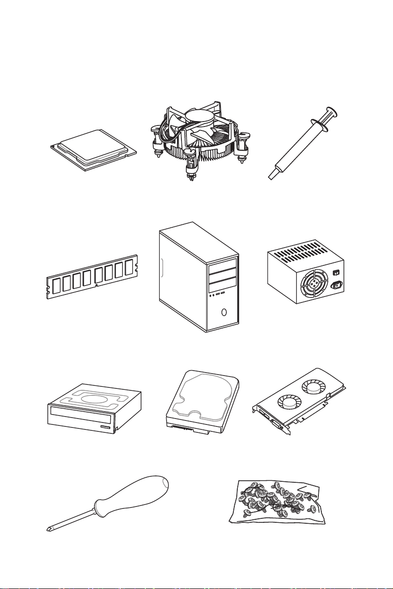
Quick Start
Preparing Tools and Components
Intel® LGA 1151 CPU
DDR4 Memory
SATA DVD Drive
CPU Fan Thermal Paste
Chassis
SATA Hard Disk Drive
Power Supply Unit
Graphics Card
Phillips Screwdriver
A Package of Screws
Quick Start
3
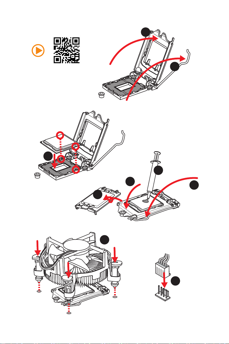
Installing a Processor
2
http://youtu.be/bf5La099urI
3
1
7
4
5
6
Quick Start
4
8
9
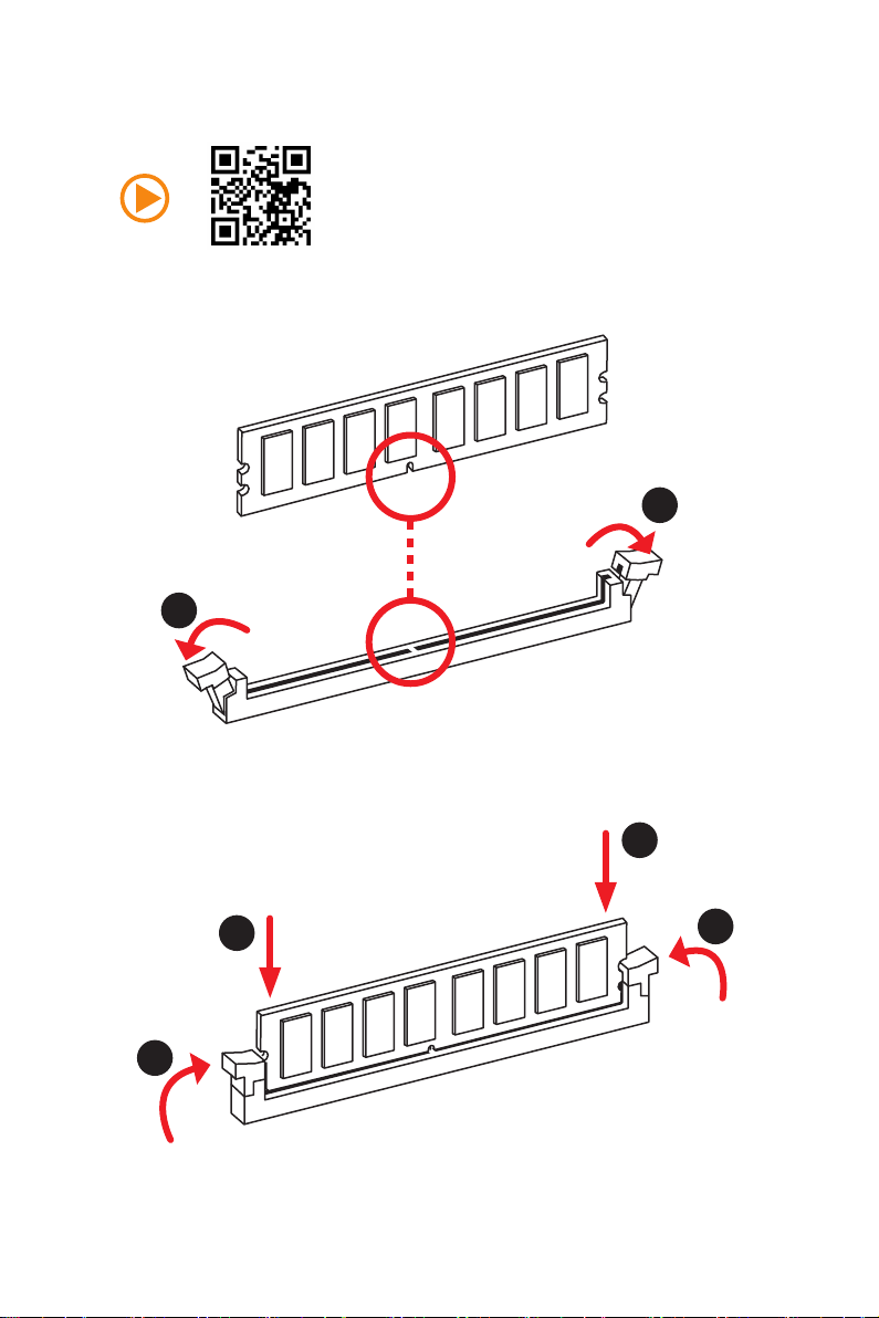
Installing DDR4 memory
1
1
2
2
3
3
Quick Start
5
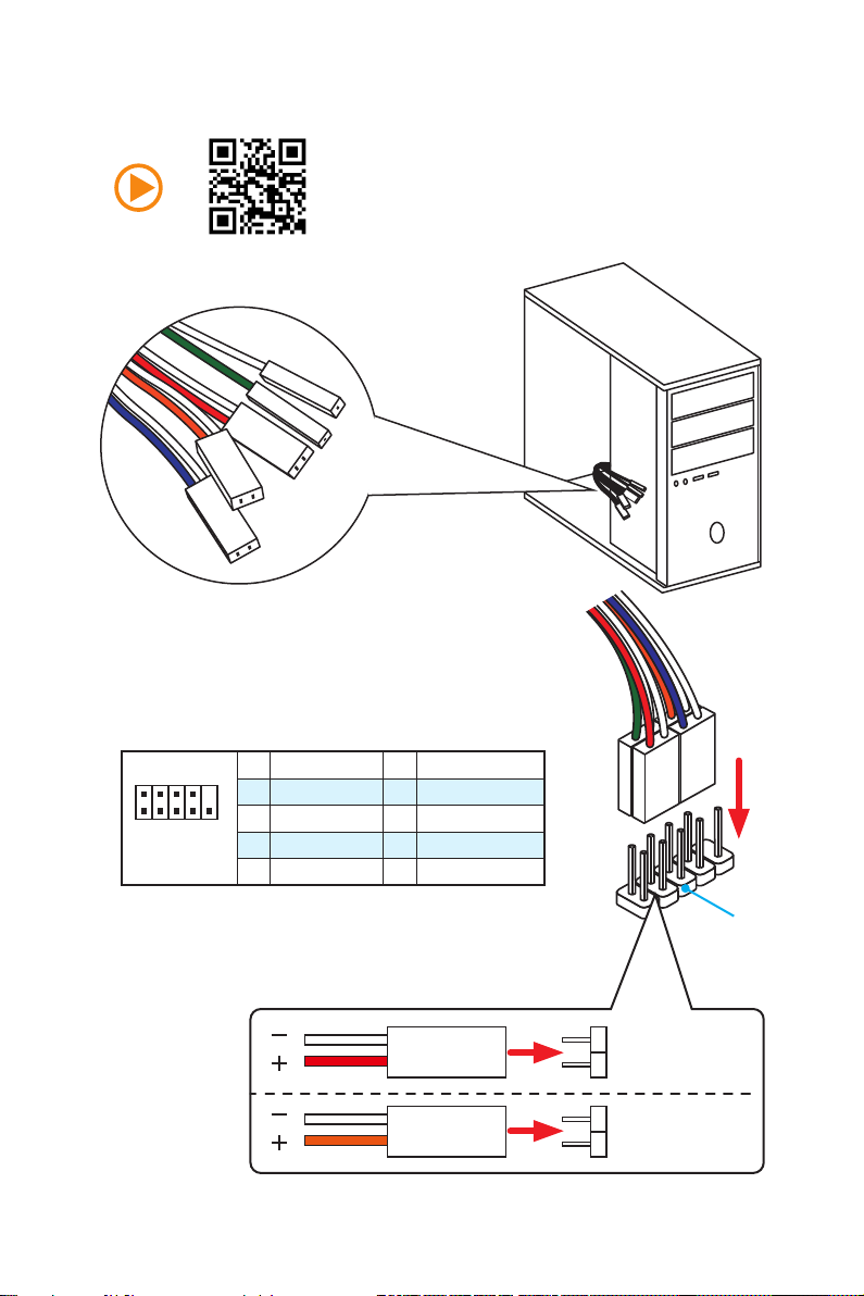
Connecting the Front Panel Header
RESET SW
POWER SW
POWER LED+
POWER LED-
HDD LED
Quick Start
6
2 10
1
JFP1
1 HDD LED + 2 Power LED +
3 HDD LED — 4 Power LED —
5 Reset Switch 6 Power Switch
9
7 Reset Switch 8 Power Switch
9 Reserved 10 No Pin
HDD LED
POWER LED
RESET SW
HDD LED
JFP1
HDD LED HDD LED +
POWER LED POWER LED +
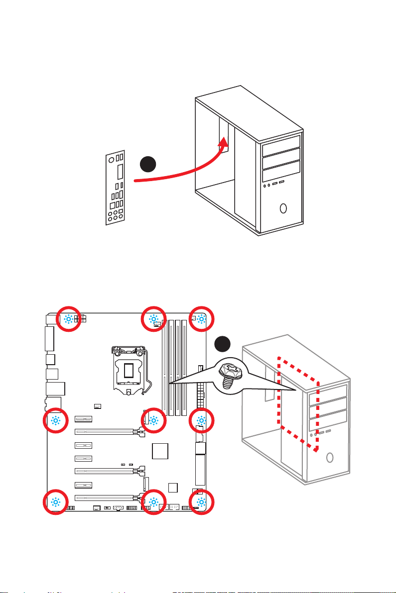
Installing the Motherboard
1
2
Quick Start
7
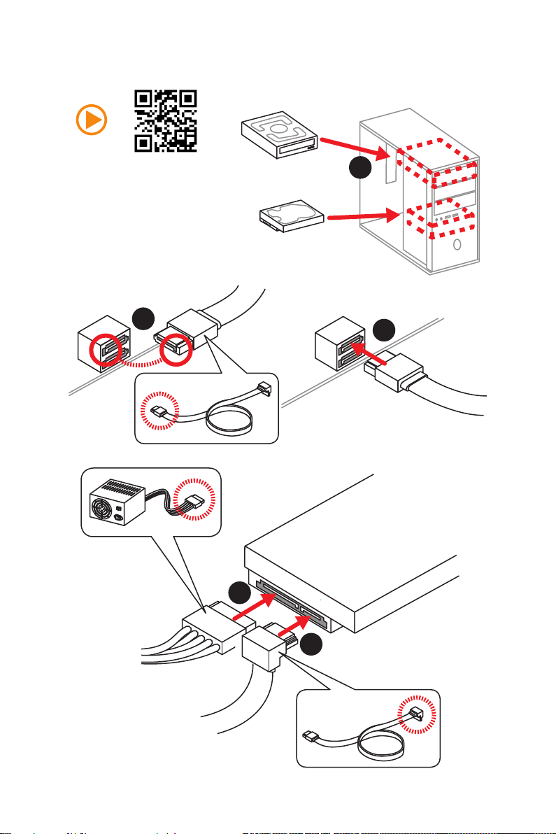
Installing SATA Drives
2
1
3
Quick Start
8
5
4
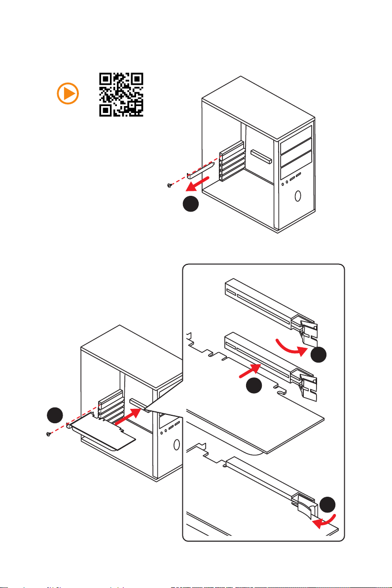
Installing a Graphics Card
1
2
3
5
4
Quick Start
9
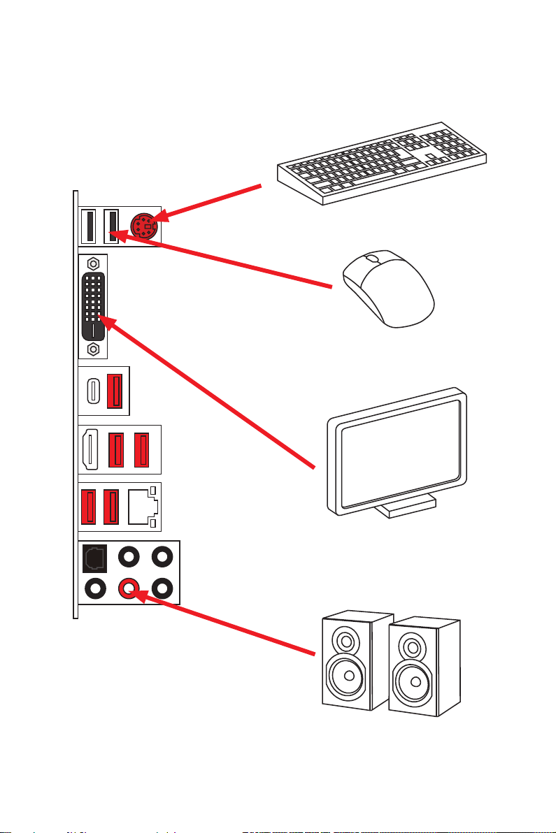
Connecting Peripheral Devices
10
Quick Start
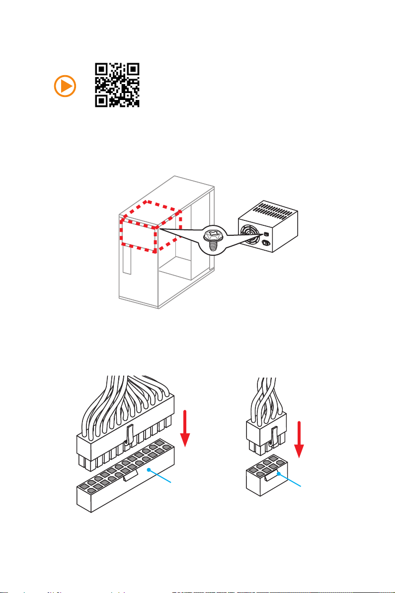
Connecting the Power Connectors
JPWR1
JPWR2
Quick Start
11
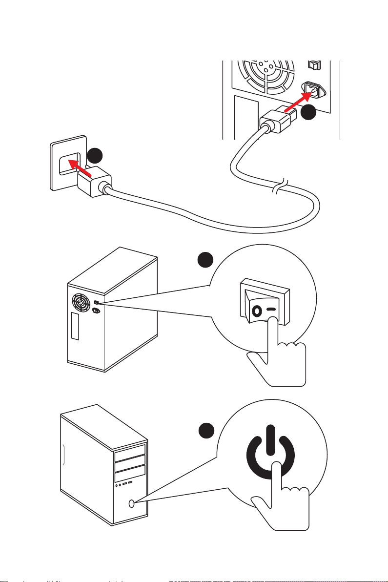
Power On
1
2
3
12
4
Quick Start

Contents
Unpacking ………………………………………………………………………………………………….1
Safety Information ………………………………………………………………………………………2
Quick Start………………………………………………………………………………………………….3
Preparing Tools and Components …………………………………………………………….. 3
Installing a Processor ……………………………………………………………………………… 4
Installing DDR4 memory ………………………………………………………………………….. 5
Connecting the Front Panel Header ………………………………………………………….. 6
Installing the Motherboard ……………………………………………………………………….. 7
Installing SATA Drives …………………………………………………………………………….. 8
Installing a Graphics Card ……………………………………………………………………….. 9
Connecting Peripheral Devices ………………………………………………………………. 10
Connecting the Power Connectors ………………………………………………………….. 11
Power On …………………………………………………………………………………………….. 12
Specifications …………………………………………………………………………………………..15
Block Diagram …………………………………………………………………………………………22
Rear I/O Panel …………………………………………………………………………………………..23
LAN Port LED Status Table ……………………………………………………………………. 23
Audio Ports Configuration ………………………………………………………………………. 23
Realtek HD Audio Manager ……………………………………………………………………. 24
Overview of Components …………………………………………………………………………26
CPU Socket …………………………………………………………………………………………. 28
DIMM Slots ………………………………………………………………………………………….. 29
PCI_E1~7: PCIe Expansion Slots……………………………………………………………. 30
SATA1~6: SATA 6Gb/s Connectors ………………………………………………………… 32
SE1_43-SE2_65: SATAe Connectors ……………………………………………………… 32
M2_1~2: M.2 Slots ………………………………………………………………………………… 33
JPWR1~2: Power Connectors ………………………………………………………………… 36
JUSB1~2: USB 2.0 Connectors………………………………………………………………. 37
JUSB3: USB 3.1 Gen1 Connector …………………………………………………………… 37
JFP1, JFP2: Front Panel Connectors ………………………………………………………. 38
JAUD1: Front Audio Connector ………………………………………………………………. 38
JTPM1: TPM Module Connector …………………………………………………………….. 38
JCOM1: Serial Port Connector ……………………………………………………………….. 39
JCI1: Chassis Intrusion Connector ………………………………………………………….. 39
CPUFAN1~2, SYSFAN1~3: Fan Connectors ……………………………………………. 40
SLOW_1: Slow Mode Booting Switch ………………………………………………………. 41
Contents
13

JBAT1: Clear CMOS (Reset BIOS) Jumper ……………………………………………… 41
POST: Debug Code LED ……………………………………………………………………….. 42
BIOS Setup ……………………………………………………………………………………………….43
Entering BIOS Setup …………………………………………………………………………….. 43
Resetting BIOS …………………………………………………………………………………….. 44
Updating BIOS ……………………………………………………………………………………… 44
Advanced Mode …………………………………………………………………………………… 47
SETTINGS …………………………………………………………………………………………… 48
Advanced …………………………………………………………………………………………….. 48
Boot ……………………………………………………………………………………………………. 54
Security ……………………………………………………………………………………………….. 55
Save & Exit ………………………………………………………………………………………….. 56
OC ……………………………………………………………………………………………………… 57
M-FLASH …………………………………………………………………………………………….. 65
OC PROFILE ……………………………………………………………………………………….. 66
HARDWARE MONITOR ………………………………………………………………………… 67
Software Description ………………………………………………………………………………..68
Installing Windows® 7/ 8.1/ 10 ………………………………………………………………… 68
Installing Drivers …………………………………………………………………………………… 68
Installing Utilities …………………………………………………………………………………… 68
COMMAND CENTER ……………………………………………………………………………. 69
LIVE UPDATE 6 …………………………………………………………………………………… 73
GAMING APP ………………………………………………………………………………………. 75
M-CLOUD ……………………………………………………………………………………………. 79
RAMDISK ……………………………………………………………………………………………. 82
Killer Network Manager …………………………………………………………………………. 83
Nahimic ……………………………………………………………………………………………….. 84
XSplit Gamecaster V2 …………………………………………………………………………… 86
®
Intel
Extreme Tuning Utility …………………………………………………………………… 90
RAID Configuration …………………………………………………………………………………..91
Using Intel® Rapid Storage Technology Option ROM ………………………………… 91
Degraded RAID Array ……………………………………………………………………………. 94
M.2 PCIe SSD RAID ……………………………………………………………………………… 96
Troubleshooting ………………………………………………………………………………………98
Regulatory Notices …………………………………………………………………………………..99
Contents
14

Specifications
CPU
Supports 6th Gen Intel® Core™ i3/i5/i7 processors, and Intel®
Pentium® and Celeron® processors for Socket LGA1151
Chipset Intel
● 4x DDR4 memory slots, support up to 64GB
Memory
● Dual channel memory architecture
● Supports ECC, un-buffered memory
● Supports Intel
● 3x PCIe 3.0 x16 slots (support x16, x8/x8, x8/x8/x4 or x8/
Expansion Slots
● 4x PCIe 3.0 x1 slots
● 1x HDMI
Onboard Graphics
Multi-GPU
● 1x DVI-D port, support a maximum resolution of
● Supports 3-Way AMD
● Supports 2-Way NVIDIA
Intel
● 6x SATA 6Gb/s ports* (4 ports reserved for SATA
● 2x M.2 slots
Storage
● 2x SATAe ports (PCIe 3.0 x2)***
● Supports Intel
* M.2, SATA and SATAe ports maximum support 1x M.2_PCIe + 6x SATAs
** The Turbo U.2 Host Card is not included, please purchase separately.
*** SATAe port is backward compatible with SATA.
®
Z170 Express Chipset
▶ Supports DDR4 3600(OC)/ 3200(OC)/ 3000(OC)/
2800(OC)/ 2600(OC)/ 2400/ 2133 MHz
®
Extreme Memory Profile (XMP)
x8/x1 modes)
™
port, support a maximum resolution of
4096×2160@24Hz, 2560×1600@60Hz
1920×1200@60Hz
®
CrossFire™ Technology
®
SLI™ Technology
®
Z170 Express Chipset
Express port)
▶ Supports PCIe 3.0 x4 and SATA 6Gb/s standards,
4.2cm/ 6cm/ 8cm length M.2 SSD cards
▶ Supports PCIe 3.0 x4 NVMe Mini-SAS SSD with Turbo
U.2 Host Card**
®
Smart Response Technology for Intel
Core™ processors
or 1x M.2_SATA + 1x M.2_PCIe + 4x SATAs. Please refer to page 34 for
M.2 slots with examples of various combination possibilities.
Continued on next page
Specications
15

Continued from previous page
®
Z170 Express Chipset
Intel
● Supports RAID 0, RAID1, RAID 5 and RAID 10 for SATA
RAID
storage devices
● Supports RAID 0 and RAID1 for M.2 PCIe storage
devices*
* M.2 PCIe RAID volume can be created with UEFI BIOS
● ASMedia
▶ 1x USB 3.1 Gen2 (SuperSpeed USB 10Gbps) port on
the back panel
▶ 1x USB 3.1 Gen2 Type-C port on the back panel
● Intel
USB
▶ 6x USB 3.1 Gen1 (SuperSpeed USB) ports (4 ports on
the back panel, 2 ports available through the internal
USB connector)
▶ 6x USB 2.0 (High-speed USB) ports (2 ports on the
back panel, 4 ports available through the internal USB
connectors)
● Realtek
Audio
● 7.1-Channel High Definition Audio
● Supports S/PDIF output
LAN 1x Killer
● 1x PS/2 keyboard/ mouse port
● 2x USB 2.0 ports
● 1x DVI-D port
● 1x USB 3.1 Gen2 port
Back Panel
Connectors
● 1x USB 3.1 Gen2 Type-C port
● 4x USB 3.1 Gen1 ports
● 1x HDMI
● 1x LAN (RJ45) port
● 1x Optical S/PDIF OUT connector
● 5x OFC audio jacks
®
ASM1142 Chipset
®
Z170 Express Chipset
®
ALC1150 Codec
™
E2400 Gigabit LAN controller
™
port
Specications
16
Continued on next page
Continued from previous page
● 1x 24-pin ATX main power connector
● 1x 8-pin ATX 12V power connector
● 6x SATA 6Gb/s connectors
● 2x SATAe connectors
● 2x USB 2.0 connectors (supports additional 4 USB 2.0
ports)
● 1x USB 3.1 Gen1 connector (supports additional 2 USB
3.1 Gen1 ports)
Internal Connectors
I/O Controller NUVOTON NCT6793 Controller Chip
Hardware Monitor
● 2x 4-pin CPU fan connectors
● 3x 4-pin system fan connectors
● 1x Front panel audio connector
● 2x Front panel connectors
● 1x TPM module connector
● 1x Serial port connector
● 1x Chassis Intrusion connector
● 1x Slow mode switch
● 1x Clear CMOS jumper
● 1x 2-Digit Debug Code LED
● CPU/System temperature detection
● CPU/System fan speed detection
● CPU/System fan speed control
Form Factor
BIOS Features
● ATX Form Factor
● 12 in. x 9.6 in. (30.5 cm x 24.4 cm)
● 1x 128 Mb flash
● UEFI AMI BIOS
● ACPI 5.0, PnP 1.0a, SM BIOS 2.8
● Multi-language
Continued on next page
Specications
17

Software
Continued from previous page
● Drivers
● COMMAND CENTER
● LIVE UPDATE 6
● FAST BOOT
● SUPER CHARGER
● GAMING APP
● M-CLOUD
● RAMDISK
● Killer Network Manager
● Nahimic Audio
● XSplit Gamecaster V2
®
● Intel
Extreme Tuning Utility
™
● Norton
● Google Chrome
Internet Security Solution
™
,Google Toolbar, Google Drive
● SteelSeries Engine 3
● CPU-Z
Continued on next page
Specications
18

Enthusiast GAMING
Features
Continued from previous page
● AUDIO BOOST 3
▶ Isolated Audio PCB
▶ EMI Shielding
▶ Dual Headphone Amplifiers
▶ High Quality Audio Capacitors
▶ Golden Audio Connectors
● GAME BOOST
▶ Easy Overclocking
● GAMING LAN
▶ Killer E2400 Ethernet
▶ Killer Network Manager
▶ EMI Shielding
▶ Electric Wave Surge
● GAMING APP
▶ System Mode Switching: OC/Gaming/Silent
▶ Gaming Hotkey
▶ Gaming Mouse Control
● Optimized Thermal Design
▶ Dual Touch Thermal Design
● Nahimic
▶ Sound Effect Equalizer
▶ Microphone Noise Reduction
▶ HD Audio Recorder
● XSplit
▶ XSplit Gamecaster
▶ XSplit Broadcaster
● GAMING CERTIFIED
Continued on next page
Specications
19

MSI Exclusive
Features
Continued from previous page
● CLICK BIOS 5
▶ EZ Mode & Advanced Mode Switching
▶ Board Explorer
▶ Hardware Monitor
● MILITARY CLASS 5
▶ Military Class Component
▶ Military Class Stability and Reliability
— ESD Protection
— EMI Protection
— Humidity Protection
— Circuit Protection
— High Temperature Protection
— Steel Armor PCIe Slots
— VGA Armor Slot
● COMMAND CENTER
▶ System Monitor
▶ Smart Fan Control
● RAMDISK
● LIVE UPDATE 6
● M-CLOUD
● CPU-Z
Continued on next page
Specications
20

Specification
Highlights
Continued from previous page
● DDR4 Boost Support
▶ Dual-Channel DDR4 Memory Support
▶ Isolated DDR4 Circuit Design
▶ DDR4 XMP Ready
● PCI Express 3.0 Support
▶ 2-Way Nvidia SLI
▶ 3-Way AMD CrossFire
TM
Support
TM
Support
● USB 3.1 Gen2 Ready
▶ USB 3.1 Gen2 (10 Gb/s) Type-C Ready
▶ USB 3.1 Gen2 (10 Gb/s) Type-A Ready
● Twin Turbo M.2 Ready
▶ Dual M.2 RAID Support
▶ PCIe 3.0 x4 (32 Gb/s) Support
▶ PCIe / SATA Dual Mode Support
● SATA Express Support
● NVMe / AHCI Driver Support
● U.2 Support (Optional)
Specications
21
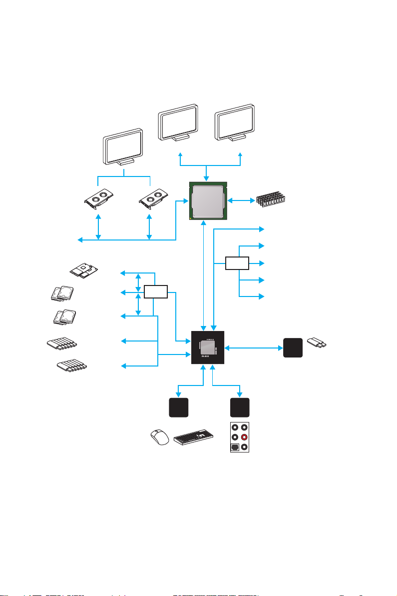
Block Diagram
x16x8
PCI Express Bus
x4
2 x M.2
2 x SATA Express
(4 x SATA 6Gb/s)
2 x SATA 6Gb/s
x2
HDMI DVI-D
DMI 3.0
Switch
PCI Express Bus
CPU
PCI Express Bus
2 Channel DDR4 Memory
x1
x1
x1
Switch
x1
x4
PCIe x1
PCIe x1
PCIe x1
PCIe x1
PCIe x4
Block Diagram
22
6 x USB 3.1 Gen1
6 x USB 2.0
LPC Bus
NV6793
Super I/O
P/S2 Mouse / Keyboard
Z170
PCI Express Bus
Realtek
ALC1150
Audio Jacks
x2
ASMEDIA
ASM1142
2 x USB 3.1 Gen2
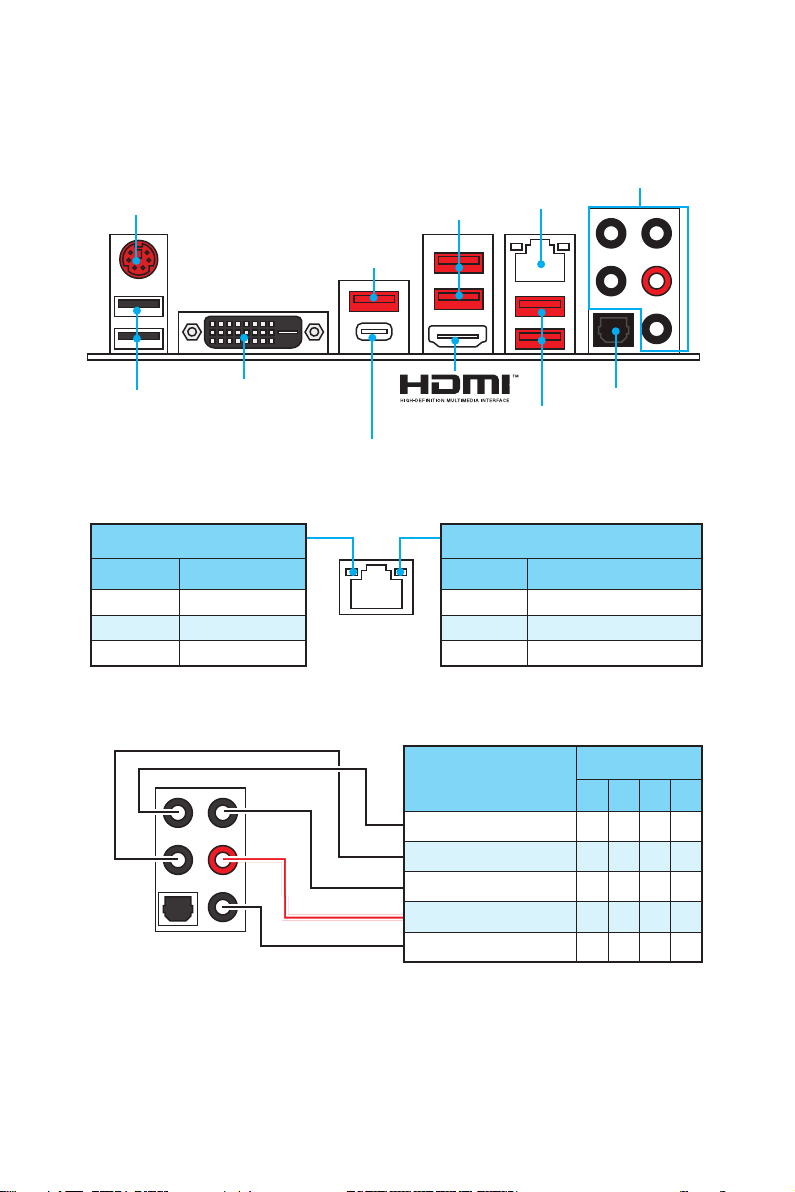
Rear I/O Panel
PS/2
USB 3.1 Gen2
USB 2.0
DVI-D
USB 3.1 Gen2 Type-C
LAN Port LED Status Table
Link/ Activity LED
Status Description
Off No link
Yellow Linked
Blinking Data activity
Audio Ports Configuration
USB 3.1 Gen1
LAN
USB 3.1 Gen1
Speed LED
Status Description
Off 10 Mbps connection
Green 100 Mbps connection
Orange 1 Gbps connection
Audio Ports
Optical S/PDIF-Out
Audio Ports
Center/ Subwoofer Out ● ●
Rear Speaker Out ● ● ●
Line-In/ Side Speaker Out ●
Line-Out/ Front Speaker Out ● ● ● ●
Mic In
Channel
2 4 6 8
(●: connected, Blank: empty)
Rear I/O Panel
23
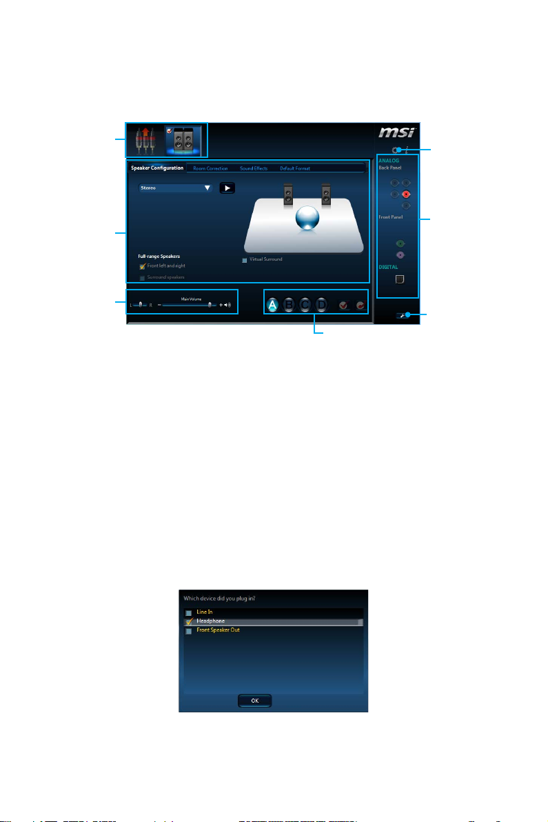
Realtek HD Audio Manager
After installing the Realtek HD Audio driver, the Realtek HD Audio Manager icon will
appear in the system tray. Double click on this icon to launch.
Device
Selection
Advanced
Settings
Application
Enhancement
Main Volume
Profiles
Jack Status
Connector
Strings
● Device Selection — allows you to select a audio output source to change the related
options. The check sign indicates the devices as default.
● Application Enhancement — the array of options will provide you a complete
guidance of anticipated sound effect for both output and input device.
● Main Volume — controls the volume or balance the right/left side of the speakers
that you plugged in front or rear panel by adjust the bar.
● Profiles — toggles between profiles.
● Advanced Settings — provides the mechanism to deal with 2 independent audio
streams.
● Jack Status — depicts all render and capture devices currently connected with your
computer.
● Connector Settings — configures the connection settings.
Auto popup dialog
When you plug into a device at an audio jack, a dialogue window will pop up asking
you which device is current connected.
Each jack corresponds to its default setting as shown on the next page.
Rear I/O Panel
24
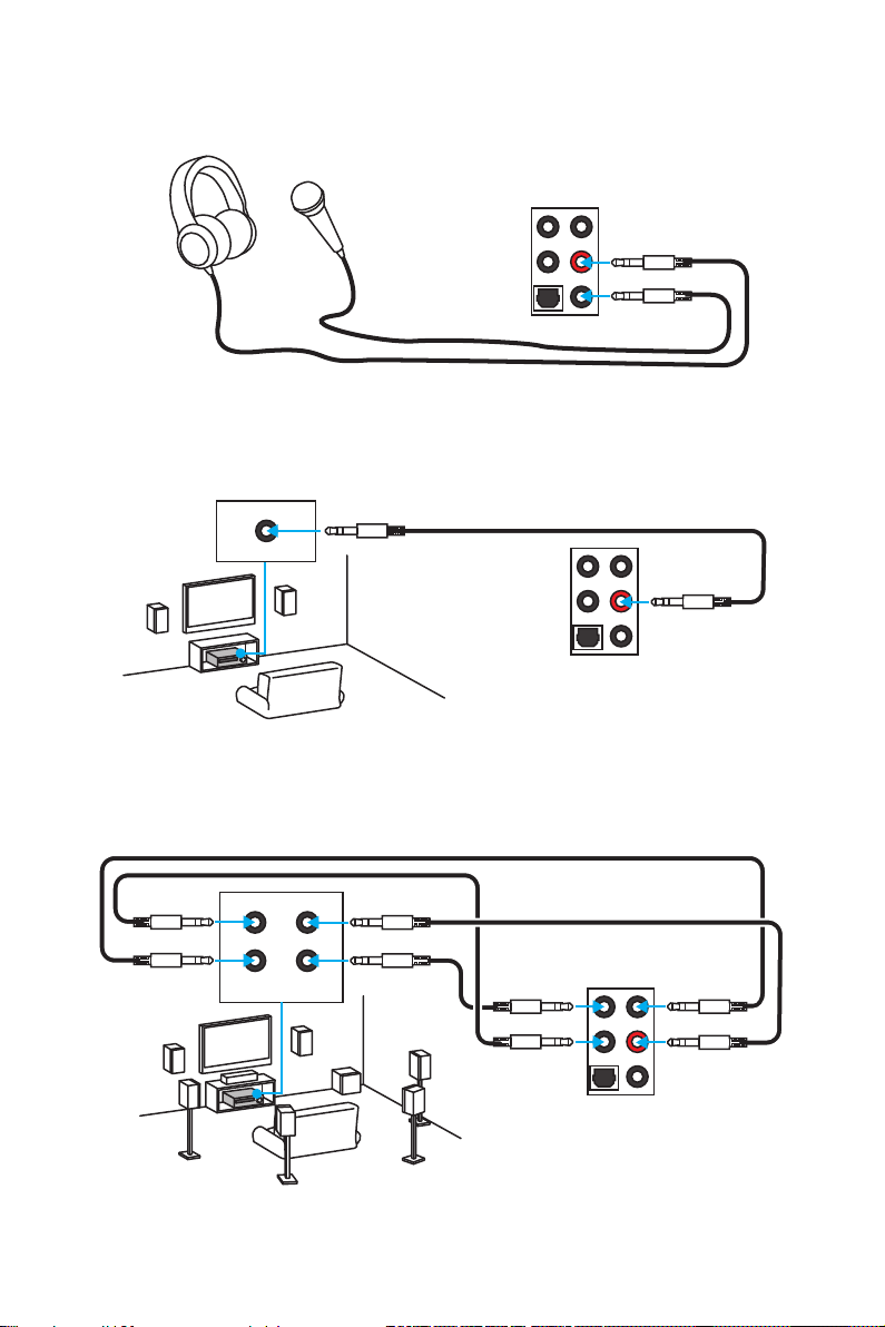
Audio jacks to headphone and microphone diagram
Audio jacks to stereo speakers diagram
AUDIO INPUT
Audio jacks to 7.1-channel speakers diagram
AUDIO INPUT
Rear Front
Side Center/
Subwoofer
Rear I/O Panel
25
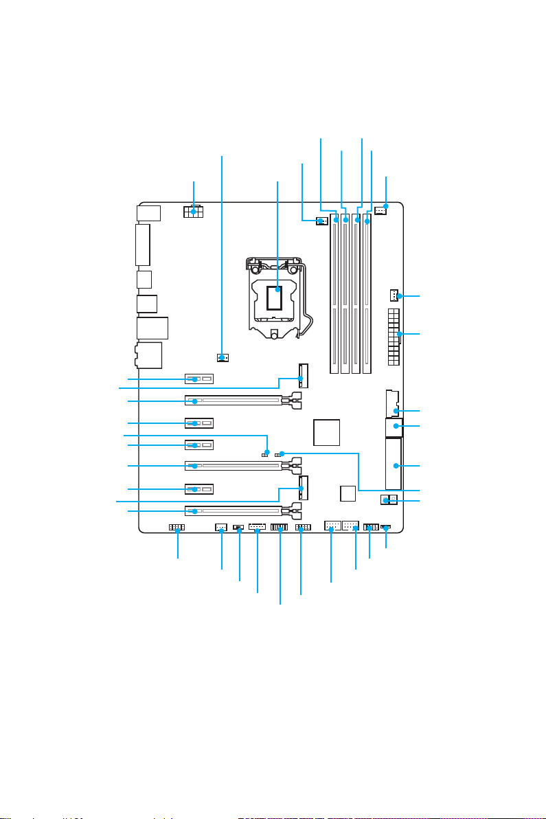
Overview of Components
PCI_E1
M2_1
PCI_E2
PCI_E3
JBAT1
PCI_E4
PCI_E5
PCI_E6
M2_2
PCI_E7
SYSFAN1 DIMM2
CPUFAN1
CPU SocketJPWR2
DIMM1
DIMM3
DIMM4
CPUFAN2
SYSFAN3
JPWR1
JUSB3
SATA1_2
SE1_43-SE2_65
JCI1
POST
* JTBT1 is used to connect a specific card.
Overview of Components
26
JAUD1
SYSFAN2
SLOW_1
JTBT1*
JTPM1
JCOM1
JUSB2
JUSB1
JFP1
JFP2
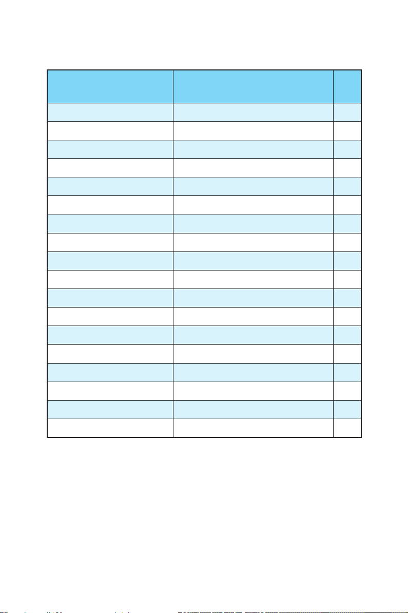
Component Contents
Port Name Port Type Page
CPUFAN1~2, SYSFAN1~3 Fan Connectors 40
CPU Socket LGA1151 CPU Socket 28
DIMM1~4 DIMM Slots 29
JAUD1 Front Audio Connector 38
JBAT1 Clear CMOS (Reset BIOS) Jumper 41
JCI1 Chassis Intrusion Connector 39
JCOM1 Serial Port Connector 39
JFP1, JFP2 Front Panel Connectors 38
JPWR1~2 Power Connectors 36
JTPM1 TPM Module Connector 38
JUSB1~2 USB 2.0 Connectors 37
JUSB3 USB 3.1 Gen1 Connector 37
M2_1~2 M.2 Slots 33
PCI_E1~7 PCIe Expansion Slots 30
POST Debug Code LED 42
SATA1~6 SATA 6Gb/s Connectors 32
SE1_43-SE2_65 SATAe Connectors 32
SLOW_1 Slow Mode Booting Switch 41
Overview of Components
27
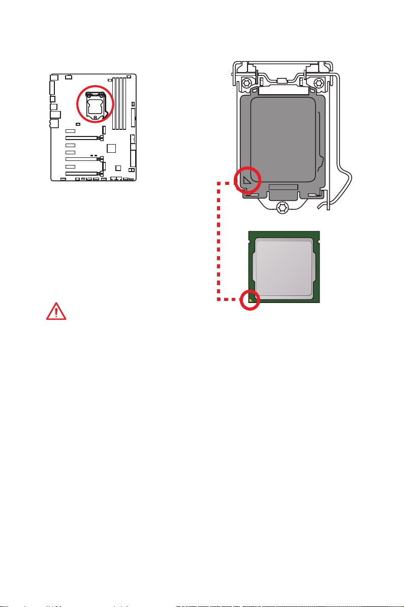
CPU Socket
Introduction to the LGA 1151 CPU
The surface of the LGA 1151 CPU has
two notches and a golden triangle to
assist in correctly lining up the CPU for
motherboard placement. The golden
triangle is the Pin 1 indicator.
Important
●
Always unplug the power cord from the power outlet before installing or removing
the CPU.
●
Please retain the CPU protective cap after installing the processor. MSI will deal
with Return Merchandise Authorization (RMA) requests if only the motherboard
comes with the protective cap on the CPU socket.
●
When installing a CPU, always remember to install a CPU heatsink. A CPU
heatsink is necessary to prevent overheating and maintain system stability.
●
Confirm that the CPU heatsink has formed a tight seal with the CPU before booting
your system.
●
Overheating can seriously damage the CPU and motherboard. Always make sure
the cooling fans work properly to protect the CPU from overheating. Be sure to
apply an even layer of thermal paste (or thermal tape) between the CPU and the
heatsink to enhance heat dissipation.
●
Whenever the CPU is not installed, always protect the CPU socket pins by covering
the socket with the plastic cap.
●
If you purchased a separate CPU and heatsink/ cooler, Please refer to the
documentation in the heatsink/ cooler package for more details about installation.
●
This motherboard is designed to support overclocking. Before attempting to
overclock, please make sure that all other system components can tolerate
overclocking. Any attempt to operate beyond product specifications is not
recommended. MSI® does not guarantee the damages or risks caused by
inadequate operation beyond product specifications.
Overview of Components
28
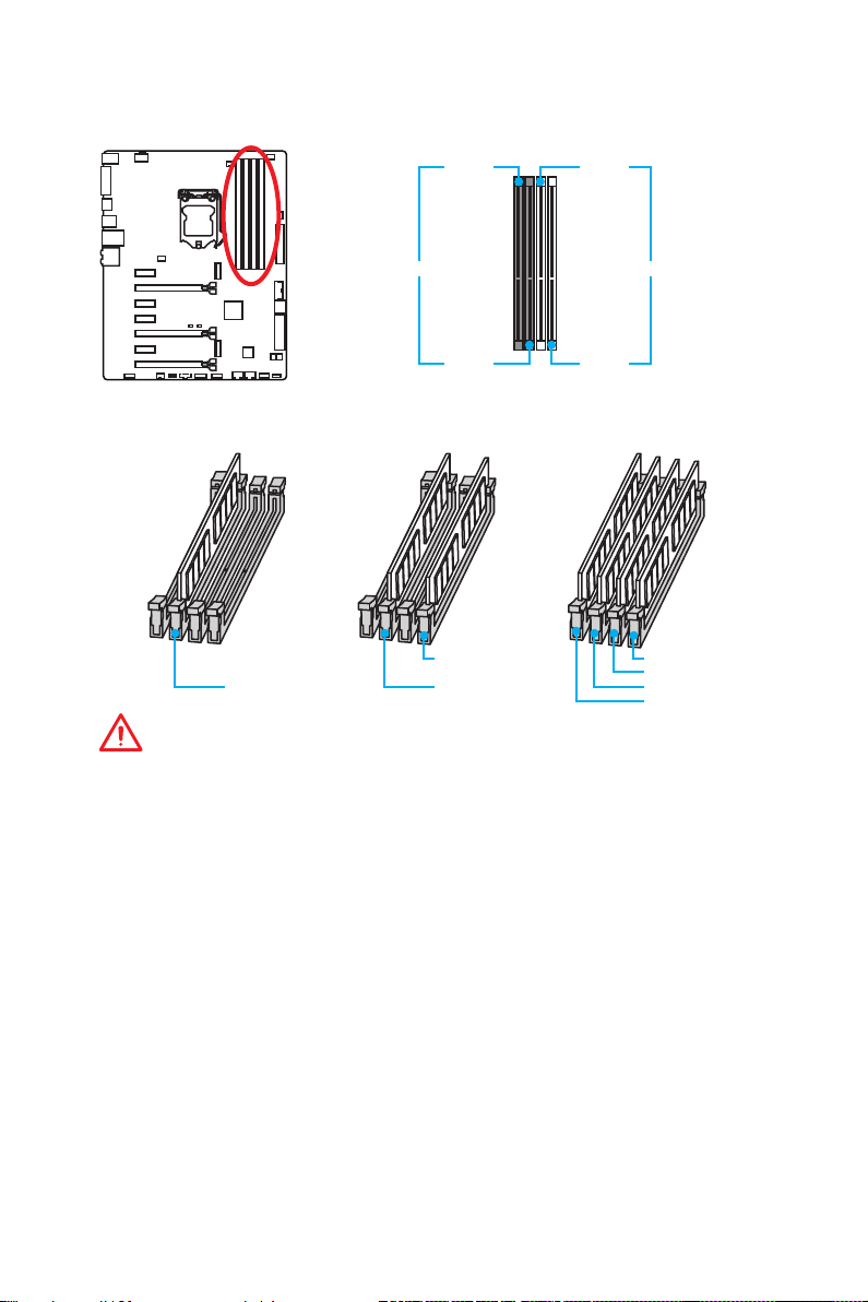
DIMM Slots
DIMM1 DIMM3
Channel A Channel B
DIMM2 DIMM4
Memory module installation recommendation
DIMM4 DIMM4
DIMM2 DIMM2 DIMM2
DIMM3
DIMM1
Important
●
Always insert memory modules in the DIMM2 slot first.
●
Due to chipset resource usage, the available capacity of memory will be a little less
than the amount of installed.
●
Based on Intel CPU specification, the Memory DIMM voltage below 1.35V is
suggested to protect the CPU.
●
Please note that the maximum capacity of addressable memory is 4GB or less
for 32-bit Windows OS due to the memory address limitation. Therefore, we
recommended that you to install 64-bit Windows OS if you want to install more than
4GB memory on the motherboard.
●
Some memory may operate at a lower frequency than the marked value when
overclocking due to the memory frequency operates dependent on its Serial
Presence Detect (SPD). Go to BIOS and find the Memory Try It! to set the
memory frequency if you want to operate the memory at the marked or at a higher
frequency.
●
It is recommended to use a more efficient memory cooling system for full DIMMs
installation or overclocking.
●
The stability and compatibility of installed memory module depend on installed CPU
and devices when overclocking.
Overview of Components
29
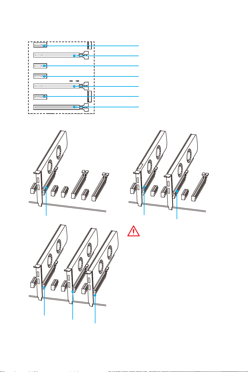
PCI_E1~7: PCIe Expansion Slots
PCI_E1: PCIe 3.0 x1 slot
PCI_E2: PCIe 3.0 x16/ x8 slot
PCI_E3: PCIe 3.0 x1 slot
PCI_E4: PCIe 3.0 x1 slot
PCI_E5: PCIe 3.0 x8 slot
PCI_E6: PCIe 3.0 x1 slot
PCI_E7: PCIe 3.0 x4/ x1 slot
Multiple graphics cards installation recommendation
x16
x8
Overview of Components
30
x8
x4
x8
x8
Important
●
PCI_E7 will only run x1 mode, when an
extension card is installed in PCI_E3/
PCI_E4/ PCI_E6 slot.
●
For a single PCIe x16 expansion
card installation with optimum
performance, using the PCI_E2 slot is
recommended.
●
When adding or removing expansion
cards, always turn off the power supply
and unplug the power supply power
cable from the power outlet. Read the
expansion card’s documentation to
check for any necessary additional
hardware or software changes.

Installing SLI graphics cards
For power supply recommendations for SLI configurations, please refer to the user
guide of your graphics card to make sure you meet all the system requirements.
To install SLI graphics cards:
1. Turn off your computer and disconnect the power cord, install two graphics cards
into the PCI_E2 and PCI_E5 slots.
2. Connect the two cards together using the SLI Bridge Connector.
3. Connect all PCIe power connectors of the graphics cards.
4. Reconnect the power cord, power up the computer and install the drivers and
software included in your graphics card package.
5. Right-click the Windows desktop and select NVIDIA Control Panel from the
menu, click on Configure SLI, Surround, PhysX in the left task pane and select
Maximize 3D performance in the SLI configuration menu, and then click Apply.
Overview of Components
31
 Loading…
File Specifications:1105/1105865-z170a_pro.pdf file (20 Feb 2023) |
Accompanying Data:
MSI Z170-A PRO Motherboard PDF Operation & User’s Manual (Updated: Monday 20th of February 2023 11:43:45 AM)
Rating: 4.1 (rated by 41 users)
Compatible devices: Z77A-G41 Series, MS-6367, MS-6380, MS-7793, P55A-G55 series, G4M-e43, 760GM-P43 Series, MEG Z490 UNIFY.
Recommended Documentation:
Operation & User’s Manual (Text Version):
(Ocr-Read Summary of Contents of some pages of the MSI Z170-A PRO Document (Main Content), UPD: 20 February 2023)
-
56, 12 Übersicht der Komponenten PCI_E1~6: PCIe Erweiterungssteckplätze PCI_E1: PCIe 3.0 x1-Steckplatz PCI_E2: PCIe 3.0 x16-Steckplatz PCI_E3: PCIe 3.0 x1-Steckplatz PCI_E4: PCIe 3.0 x4-Steckplatz PCI_E5: PCIe 3.0 x1-Steckplatz PCI_E6: PCIe 3.0 x1-Steckplatz Mehrere Grafikkarten Einbauempfehlung Wichtig ● Für die Installation einer einzelnen PCIe x16 Erweiterungskarte mit optimaler Leistung, empfehlen wir PCI_E2 Steckplatz zu verwenden. ● Achten Sie darauf, dass Sie den Strom abschalte…
-
32, 22 Overview of Components JCI1: Chassis Intrusion Connector This connector allows you to connect the chassis intrusion switch cable. Normal (default) Trigger the chassis intrusion event Using chassis intrusion detector 1. Connect the JCI1 connector to the chassis intrusion switch/ sensor on the chassis. 2. Close the chassis cover. 3. Go to BIOS > Settings > Security > Chassis Intrusion Configuration. 4. Set Chassis Intrusion…
-
119, 7 Задняя панель ввода/ вывода Задняя панель ввода/ вывода PS/2 LAN USB 3.1 Gen1 VGA Порты Аудио USB 2.0 DisplayPort Подключение/ Работа индикатора Состояние Описание Выкл. Не подключен Желтый Подключен Мигает Передача данных Скорость передачи данных …
-
33, MSI Z170-A PRO 23 BIOS Setup BIOS Setup The default settings offer the optimal performance for system stability in normal conditions. You should always keep the default settings to avoid possible system damage or failure booting unless you are familiar with BIOS. Important ● BIOS items are continuously update for better system performance. Therefore, the description may be slightly different from the latest BIOS and should be for reference only. Yo…
-
23, 13 Overview of Components SATA1~6: SATA 6Gb/s Connectors These connectors are SATA 6Gb/s interface ports. Each connector can connect to one SATA device. SATA5 SATA1 SATA2 SATA6 SATA3 SATA4 SE1_21-SE2_65: SATAe Connectors These connectors are SATAe (SATA Express) interface ports. Each SATAe connector can be used with a single SATAe device or two legacy SATA devices. SATA1 SATA5 SATA2 SATA6 SE1_21 (SATA_EX1) SE2_65 (SATA_EX2) Important ● Please do not fold the SATA or SAT…
-
124, MSI Z170-A PRO 12 Компоненты материнской платы PCI_E1~6: Слоты расширения PCIe PCI_E1: PCIe 3.0 x1 слот PCI_E2: PCIe 3.0 x16 слот PCI_E3: PCIe 3.0 x1 слот PCI_E4: PCIe 3.0 x4 слот PCI_E5: PCIe 3.0 x1 слот PCI_E6: PCIe 3.0 x1 слот Рекомендации по установке нескольких видеокарт Внимание! ● При у�…
-
123, 11 Компоненты материнской платы Слоты DIMM DIMM1 DIMM3 Канал A Канал B DIMM2 DIMM4 Рекомендации по установке модулей памяти DIMM4 DIMM4 DIMM3 DIMM2 DIMM2 DIMM2 DIMM1 Внимание! ● Всегда устанавливайте модуль памяти сначала в слот DIMM2. ● В связи со спецификой использования ресурсов чипсета, доступный об�…
-
115, 3 Технические характеристики Технические характеристики Процессор Поддержка процессоров Intel ® Core ™ i3/i5/i7, Intel ® Pentium ® и Celeron ® 6-го поколения для сокета LGA1151 Чипсет Intel ® Z170 Память ● 4x DDR4 слота памяти с поддержкой до 64 ГБ ▶ Поддержка DDR4 3200(OC)/ 3000(OC)/ 2800(OC…
-
127, 15 Компоненты материнской платы Таблица комбинации M.2/ SATA и SATAe Слот Доступные разъемы SATA/ SATA Express M2_1 Пусто M.2 SATA M.2 PCIe SATA_EX1 & EX2 ✓ ✓ ✓ SATA1 ✓ ─ ✓ SATA2 ✓ ─ ✓ SATA3 ✓ ✓ ─ SATA4 ✓ ✓ ─ SATA5 ✓ ✓ ✓ SATA6 ✓ ✓ ✓ (✓: Доступно, ─: Недоступно) Внимание! ● Порт�…
-
8, VIII Quick Start Connecting Peripheral Devices/ Peripheriegeräte/ Connecter un périphérique anschliessen/ Подключение периферийных устройств
… -
98, 20 Vue d’ensemble des composants 1 2 10 9 1 DCD 2 SIN 3 SOUT 4 DTR 5 Ground 6 DSR 7 RTS 8 CTS 9 RI 10 No Pin JCOM1: Connecteur de port série Ce connecteur vous permet de relier un port série en option. 1 2 26 25 1 RSTB# 2 AFD# 3 PRND0 4 ERR# 5 PRND1 6 PINIT# 7 PRND2 8 LPT_SLIN# 9 PRND3 10 Ground 11 PRND4 12 Ground 13 PRND5 14 Ground 15 PRND6 16 Ground 17 PRND7 18 Ground 19 ACK# 20 Ground 21 BUSY 22 Ground 23 PE 24 Ground 25 SLCT 26 No Pin JLPT1:…
-
73, 29 BIOS-Setup ▶OC GENIE Function Control [By Onboard Button] (optional) Aktiviert die OC GENIE-Funktion durch einen Klick auf die virtuelle OC GENIE Taste im BIOS oder die physische OC GENIE Taste auf dem Motherboard. Durch die Aktivierung der OC GENIE-Funktion wird ein automatisches Übertakten mit einem von MSI optimierten Übertaktungsprofil ermöglicht. [By BIOS Options] Aktivieren Sie die OC GENIE Funktion durch einen Klick auf die virtuelle Taste «OC GENIE …
-
63, 19 Übersicht der Komponenten CPUFAN1~2, SYSFAN1~3: Stromanschlüsse für Lüfter Diese Anschlüsse können im PWM (Pulse Width Modulation) Modus oder Spannungsmodus betrieben werden. Im PWM-Modus bieten die Lüfteranschlüsse konstante 12V Ausgang und regeln die Lüftergeschwindigkeit per Drehzahlsteuersignal. Im Spannungsmodus bestimmen die Lüfteranschlüsse die Lüftergeschwindigkeit durch Ändern d…
-
129, MSI Z170-A PRO 17 Компоненты материнской платы JUSB3~4: Разъемы USB 3.1 Gen1 Данные разъемы предназначены для подключения портов USB 3.1 Gen1 на передней панели. 1 10 11 20 1 Power 11 USB2.0+ 2 USB3_RX_DN 12 USB2.0- 3 USB3_RX_DP 13 Ground 4 Ground 14 USB3_TX_C_DP 5 USB3_TX_C_DN 15 USB3_TX_C_DN 6 USB3_TX_C_DP 16 Ground 7 Ground 17 USB3_RX_DP 8 USB2.0- 18 USB3_RX_DN 9 …
-
93, 15 Vue d’ensemble des composants Tableau de combinaison M.2/ SATA & SATAe Slots Connecteurs SATA/ SATAe disponibles M2_1 Vide M.2 SATA M.2 PCIe SATA_EX1 & EX2 ✓ ✓ ✓ SATA1 ✓ ─ ✓ SATA2 ✓ ─ ✓ SATA3 ✓ ✓ ─ SATA4 ✓ ✓ ─ SATA5 ✓ ✓ ✓ SATA6 ✓ ✓ ✓ (✓: disponible, ─: indisponible) Important ● Les ports SATA1~2 sont indisponibles pendant l’installation du module d’interface M.2 SATA d…
-
108, 30 Conguration du BIOS [Disabled] Désactive cette fonction. [Profile 1] Utilise le profil d’overclocking n°1 des modules de mémoire XMP installés. [Profile 2] Utilise le profil d’overclocking n°2 des modules de mémoire XMP installés. ▶DRAM Frequency [Auto] Définit la fréquence de la mémoire. Veuillez noter que les résultats de l’overclocking ne sont pas garantis. ▶Adjusted DRAM Frequency Affiche la fréquence ajustée de la mémoi…
-
3, III Quick Start 1 1 2 2 3 3 Installing DDR4 memory/ Installation des DDR4-Speichers/ Installer une mémoire DDR4/ Установка памяти DDR4 http://youtu.be/T03aDrJPyQs
…
-
MSI Z170-A PRO User Manual
-
MSI Z170-A PRO User Guide
-
MSI Z170-A PRO PDF Manual
-
MSI Z170-A PRO Owner’s Manuals
Recommended: PNVR300, CTRT2812W(G), 216BW, FDB510CF, KBRO36FMX00
Links & Tools
Operating Impressions, Questions and Answers:
Table of Contents for MSI Z170-A PRO:
-
26 Настройка BIOS ● Переключатель XMP — нажмите на соответствующий внутренний значок, чтобы включить/ выключить X.M.P. (Extreme Memory Profile). Для выбора профиля X.M.P. переключите внешний значок. Этот переключатель доступен только в случае, если установлен модуль
-
24 Настройка BIOS Сброс BIOS В некоторых ситуациях необходиимо выполнить восстановление настройек BIOS до значений по умолчанию. Существует несколько способов сброса настроек: ● Войдите в BIOS и нажмите клавишу F6
-
34 Описание программного обеспечения Описание программного обеспечения Установка Windows ® 7/ 8.1/ 10 1. Включите компьютер. 2. Вставьте диск Windows ® 7/ 8.1/ 10 в привод для оптических дисков. Примечание: Из-за ограничений, накладываемых установщиком Windows ® 7, USB оптические приводы и флеш накопи
-
17 Übersicht der Komponenten JUSB3~4: USB 3.1 Gen1 Anschlüsse Mit diesen Anschlüssen können Sie die USB 3.1 Gen1 Anschlüsse auf dem Frontpanel verbinden. 1 10 11 20 1 Power 11 USB2.0+ 2 USB3_RX_DN 12 USB2.0- 3 USB3_RX_DP 13 Ground 4 Ground 14 USB3_TX_C_DP 5 USB3_TX_C_DN 15 USB3_TX_C_DN 6 USB3_TX_C_DP 16 Ground 7 Ground 17 USB3_RX_DP 8 USB2.0- 18 USB3_RX_DN 9 USB2.0+ 19 Power 10 Ground 20 No Pin Wichtig Bitte beachten Sie, dass Sie die mit Stromführende Leitung und Erdleitung bezeichneten
-
17 Компоненты материнской платы JUSB3~4: Разъемы USB 3.1 Gen1 Данные разъемы предназначены для подключения портов USB 3.1 Gen1 на передней панели. 1 10 11 20 1 Power 11 USB2.0+ 2 USB3_RX_DN 12 USB2.0- 3 USB3_RX_DP 13 Ground 4 Ground 14 USB3_TX_C_DP 5 USB3_TX_C_DN 15 USB3_TX_C_DN 6 USB3_TX_C_DP 16 Ground 7 Ground 17 USB3_RX_DP 8 USB2.0- 18 USB3_RX_DN 9 USB2.0+ 19 Power 10 Ground 20 No Pin Внимание! Помните,
-
23 Настройка BIOS Настройка BIOS Настройки по умолчанию обеспечивают оптимальную производительность и стабильность системы при нормальных условиях. Если вы недостаточно хорошо знакомы с BIOS, всегда устанавливайте настройки по умолчанию. Это позволит избежать возможных повреждений системы, а также проблем с за
-
13 Übersicht der Komponenten SATA1~6: SATA 6Gb/s Anschlüsse Diese Anschlüsse basieren auf der Hochgeschwindigkeitsschnittstelle SATA 6Gb/s. Pro Anschluss kann ein SATA Gerät angeschlossen werden. SATA5 SATA1 SATA2 SATA6 SATA3 SATA4 SE1_21-SE2_65: SATAe Anschlüsse Diese Anschlüsse sind SATAe (SATA Express) Schnittstellenmodule. Pro SATAe Anschluss kann eine einzige SATA-Gerät oder zwei ältere
-
32 Conguration du BIOS ▶Intel VT-D Tech [Enabled] Active ou désactive la technologie Intel VT-D (Intel Virtualization for Direct I/O). ▶Hardware Prefetcher [Enabled] Active ou désactive le prefetcher matériel (MLC Streamer prefetcher). [Enabled] Permet au prefetcher matériel d’acquérir automatiquement les données et les instructions dans le cache L2 de la mémoire pour ajuster les performances du pro
-
33 Conguration du BIOS ▶CFG Lock [Enabled] Verrouille ou déverrouille la fonction MSR 0xE2[15], CFG lock bit. [Enabled] Verrouille le CFG lock bit. [Disabled] Déverrouille le CFG lock bit. ▶EIST [Enabled] Active ou désactive Enhanced Intel ® SpeedStep Technology. Ce menu apparaît lorsque OC Explore Mode est mis en Normal. [Enabled] Active la technologie EIST pour ajuster la tension du processeur et de la fréquence du cœur de manière dynamique. Cela diminue la consommation d’énergie et la production de cha
-
13 Vue d’ensemble des composants SATA1~6: Connecteurs SATA 6 Gb/s Ces connecteurs utilisent une interface SATA 6 Gb/s. Chaque connecteur peut être relié à un appareil SATA. SATA5 SATA1 SATA2 SATA6 SATA3 SATA4 SE1_21-SE2_65: Connecteurs SATA Express Ces connecteurs utilisent une interface SATAe (SATA Express). Chaque connecteur SATAe peut être utilisé avec un périphérique
-
2 Безопасное использование продукции Безопасное использование продукции ● Компоненты, входящие в комплект поставки могут быть повреждены статическим электричеством. Для успешной сборки компьютера, пожалуйста, следуйте указаниям ниже. ● Убедитесь, что все компоненты компьютера подкл�
-
19 Overview of Components CPUFAN1~2, SYSFAN1~3: Fan Connectors Fan connectors can be classified as PWM (Pulse Width Modulation) Mode and Voltage Mode. PWM Mode fan connectors provide constant 12V output and adjust fan speed with speed control signal. Voltage Mode fan connectors control fan speed by changing voltage. Therefore, when you plug a 3-pin (Non-PWM) fan to a PWM Mode fan connector, the fan speed will be always maintained at 100%, and that could be noisy. 1 CPUFAN1 1 CPUFAN2 1 Ground
-
10 Vue d’ensemble des composants Socket processeur Présentation du socket LGA 1151 Sur le socket LGA 1151, vous remarquerez deux encoches et un triangle jaune servant d’indicateur pour placer le processeur dans la bonne position sur la carte mère. Le triangle jaune correspond à la broche 1 du processeur. Important ● Avant d’installer ou de retirer le processeur du socket, veillez à toujours débrancher le câble d’alimentation de la prise éle
Questions, Opinions and Exploitation Impressions:
You can ask a question, express your opinion or share our experience of MSI Z170-A PRO device using right now.