
I
Quick Start
Quick Start
Thank you for purchasing the MSI
®
X470 GAMING PLUS MAX
motherboard. This Quick Start section provides demonstration
diagrams about how to install your computer. Some of the
installations also provide video demonstrations. Please link to the
URL to watch it with the web browser on your phone or tablet. You
may have even link to the URL by scanning the QR code.
Kurzanleitung
Danke, dass Sie das MSI
®
X470 GAMING PLUS MAX Motherboard
gewählt haben. Dieser Abschnitt der Kurzanleitung bietet eine Demo
zur Installation Ihres Computers. Manche Installationen bieten
auch die Videodemonstrationen. Klicken Sie auf die URL, um diese
Videoanleitung mit Ihrem Browser auf Ihrem Handy oder Table
anzusehen. Oder scannen Sie auch den QR Code mit Ihrem Handy,
um die URL zu öffnen.
Présentation rapide
Merci d’avoir choisi la carte mère MSI
®
X470 GAMING PLUS MAX.
Ce manuel fournit une rapide présentation avec des illustrations
explicatives qui vous aideront à assembler votre ordinateur. Des
tutoriels vidéo sont disponibles pour certaines étapes. Cliquez sur
le lien fourni pour regarder la vidéo sur votre téléphone ou votre
tablette. Vous pouvez également accéder au lien en scannant le QR
code qui lui est associé.
Быстрый старт
Благодарим вас за покупку материнской платы MSI
®
X470
GAMING PLUS MAX. В этом разделе представлена информация,
которая поможет вам при сборке комьютера. Для некоторых
этапов сборки имеются видеоинструкции. Для просмотра
видео, необходимо открыть соответствующую ссылку в
веб—браузере на вашем телефоне или планшете. Вы также
можете выполнить переход по ссылке, путем сканирования
QR-кода.
Смотреть руководство для MSI X470 Gaming Plus Max ниже. Все руководства на ManualsCat.com могут просматриваться абсолютно бесплатно. Нажав кнопку «Выбор языка» вы можете изменить язык руководства, которое хотите просмотреть.

MANUALSCAT | RU
Вопросы и ответы
У вас есть вопрос о MSI X470 Gaming Plus Max, но вы не можете найти ответ в пользовательском руководстве? Возможно, пользователи ManualsCat.com смогут помочь вам и ответят на ваш вопрос. Заполните форму ниже — и ваш вопрос будет отображаться под руководством для MSI X470 Gaming Plus Max. Пожалуйста, убедитесь, что вы опишите свои трудности с MSI X470 Gaming Plus Max как можно более детально. Чем более детальным является ваш вопрос, тем более высоки шансы, что другой пользователь быстро ответит на него. Вам будет автоматически отправлено электронное письмо, чтобы проинформировать вас, когда кто-то из пользователей ответит на ваш вопрос.
Задать вопрос о MSI X470 Gaming Plus Max
Страница: 1
1
Содержание
Содержание
Безопасное использование продукции……………………………………………… 2
Технические характеристики……………………………………………………………… 3
Задняя панель портов ввода/ вывода ……………………………………………….. 8
Таблица состояний индикатора порта LAN…………………………………………… 8
Конфигурация портов Аудио…………………………………………………………………. 8
Менеджер Realtek HD Audio…………………………………………………………………….. 9
Компоненты материнской платы……………………………………………………… 11
Процессорный сокет ……………………………………………………………………………. 12
Слоты DIMM ………………………………………………………………………………………….. 13
PCI_E1~6: Слоты расширения PCIe……………………………………………………….. 14
M2_1~2: Разъем M.2 (Ключ M)………………………………………………………………… 16
SATA1~6: Разъемы SATA 6Гб/с ……………………………………………………………….. 17
JLPT1: Разъем параллельного порта……………………………………………………. 17
CPU_PWR1, CPU_PWR2, ATX_PWR1: Разъемы питания ………………………….. 18
JUSB1~2: Разъемы USB 2.0…………………………………………………………………….. 19
JUSB3~4: Разъемы USB 3.2 Gen1 ……………………………………………………………. 19
CPU_FAN1, PUMP_FAN1, SYS_FAN1~4: Разъемы вентиляторов……………… 20
JAUD1: Разъем аудио передней панели……………………………………………….. 21
JCI1: Разъем датчика открытия корпуса ……………………………………………… 21
JFP1, JFP2: Разъемы передней панели ………………………………………………… 22
JTPM1: Разъем модуля TPM ………………………………………………………………….. 22
JCOM1: Разъем последовательного порта …………………………………………… 23
JRGB1, JRGB2: Разъем RGB LED…………………………………………………………….. 23
JBAT1: Джампер очистки данных CMOS (Сброс BIOS)…………………………… 24
CLR_CMOS1: Кнопка очистки данных CMOS…………………………………………. 24
Настройка BIOS …………………………………………………………………………………… 25
Вход в настройки BIOS …………………………………………………………………………. 25
Сброс BIOS ……………………………………………………………………………………………. 26
Обновление BIOS………………………………………………………………………………….. 26
Режим EZ ………………………………………………………………………………………………. 27
Режим разгона …………………………………………………………………………………….. 29
Меню OC ……………………………………………………………………………………………….. 30
Описание программного обеспечения…………………………………………….. 35
Установка Windows®
10………………………………………………………………………….. 35
Установка драйверов …………………………………………………………………………… 35
Установка утилит …………………………………………………………………………………. 35
Страница: 2
2 Безопасное использование продукции
Безопасноеиспользованиепродукции
y Компоненты, входящие в комплект поставки могут быть повреждены
статическим электричеством. Для успешной сборки компьютера,
пожалуйста, следуйте указаниям ниже.
y Убедитесь, что все компоненты компьютера подключены должным
образом. Ослабленные соединения компонентов могут привести как к сбоям
в работе, так и полной неработоспособности компьютера.
y Чтобы избежать повреждений компонентов платы всегда держите ее за
края.
y При сборке комьютера рекомендуется пользоваться электростатическим
браслетом. В случае, если это невозможно, перед работой с платой снимите
электростатический заряд со своего тела, прикоснувшись к металлическому
предмету.
y В случае, если материнская плата не установлена в корпус, храните ее в
антистатической упаковке или на антистатическом коврике.
y Перед включением компьютера убедитесь, что все винты крепления и
другие металлические компоненты на материнской плате и внутри корпуса
надежно зафиксированы.
y Не включайте компьютер, если сборка не завершена. Это может привести к
повреждению компонентов, а также травмированию пользователя.
y Если вам нужна помощь на любом этапе сборки компьютера, пожалуйста,
обратитесь к сертифицированному компьютерному специалисту.
y Всегда выключайте питание и отсоединяйте шнур питания от
электрической розетки перед установкой или удалением любого
компонента компьютера.
y Сохраните это руководство для справки.
y Не допускайте воздействия на материнскаую плату высокой влажности.
y Перед тем как подключить блок питания компьютера к электрической
розетке убедитесь, что напряжение электросети соответствует напряжению,
указанному на блоке питания.
y Располагайте шнур питания так, чтобы на него не могли наступить люди.
Не ставьте на шнур питания никаких предметов.
y Необходимо учитывать все предостережения и предупреждения,
указанные на материнской плате.
y При возникновении любой из перечисленных ниже ситуаций обратитесь в
сервисный центр для проверки материнской платы:
Попадание жидкости внутрь компьютера.
Материнская плата подверглась воздействию влаги.
Материнская плата не работает должным образом или невозможно
наладить ее работу в соответствии с руководством пользователя.
Материнская плата получила повреждения при падении.
Материнская плата имеет явные признаки повреждения.
y Не храните материнскую плату в местах с температурой выше 60 °C (140 °F),
так как это может привести к ее повреждению.the motherboard.
Страница: 3
3
Технические характеристики
Технические характеристики
Процессор
Поддержка процессоров AMD Ryzen™ 1-го, 2-го и
3-го поколения/ процессоров Ryzen™ с видеокартой
Radeon™ Vega и процессоров AMD Ryzen™ 2-го
поколения с видеокартой Radeon™/ процессоров
Athlon™ для настольных ПК с видеокартой Radeon™
Vega для сокета AM4
Чипсет AMD®
X470
Память
y 4x слота памяти DDR4 с поддержкой до 64 ГБ
Поддержка DDR4 1866/ 2133/ 2400/ 2667 МГц по
стандартам JEDEC, и 2667/ 2800/ 2933/ 3000/ 3066/
3200/ 3466 МГц с поддержкой A-XMP OC MODE*
y Двухканальная архитектура памяти
y Поддержка non-ECC UDIMM памяти
y Поддержка ECC UDIMM памяти
* Процессоры Athlon™ с видеокартой Radeon™ Vega максимально
поддерживают 2400 МГц. Поддерживающая частота памяти зависит
от моделя установленного процессора. Пожалуйста, обратитесь www.
msi.com для получения дополнительной информации о совместимых
памяти.
Слоты
расширения
y 2x слота PCIe 3.0 x16 (PCIE_1, PCIE_4)
Процессоры AMD Ryzen™ 1-го, 2-го и 3-го
поколения поддерживают режим x16/x0, x8/x8
Процессоры Ryzen™ с видеокартой Radeon™
Vega и процессоры AMD Ryzen™ 2-го поколения с
видеокартой Radeon™ поддерживают режим x8/x0
Процессоры Athlon™ с видеокартой Radeon™ Vega
поддерживают режим x4/x0
y 1x слот PCIe 2.0 x16 (PCIE_6, поддержка режима x4)*
y 3x слота PCIe 2.0 x1
* Слот PCI_E6 будет недоступен при установке M.2 PCIe SSD в разъеме
M2_2.
Встроенная
графика
y 1x порт DVI-D, с поддержкой максимального
разрешения 1920×1200@60Гц*
y 1x порт HDMI™ 1.4, с поддержкой максимального
разрешения 4096×2160@30Гц*
* Поддерживается только при использовании процессоров Ryzen™ с
видеокартой Radeon™ Vega и процессоров AMD Ryzen™ 2-го поколения
с видеокартой Radeon™/ процессоров Athlon™ с видеокартой Radeon™
Vega
* Максимальная общая память — 2048 МБ
Продолжение на следующей странице
Страница: 4
4 Технические характеристики
Продолжение с предыдущей страницы
Поддержка Multi-
GPU
y Процессоры AMD Ryzen™ 1-го, 2-го и 3-го поколения
Поддержка технологии 3-Way AMD®
CrossFire™
y Процессоры Ryzen™ с видеокартой Radeon™
Vega и процессоры AMD Ryzen™ 2-го поколения
с видеокартой Radeon™/ процессоры Athlon™ с
видеокартой Radeon™ Vega
Поддержка технологии 2-Way AMD®
CrossFire™
LAN 1x Гигабитный сетевой контроллер Realtek®
8111H
Подключение
накопителей
y 6x портов SATA 6Гб/с (для чипсета AMD®
X470)
y 2x разъема M.2 (Ключ M)*
Разъем M2_1 (для процессоров AMD®
)
поддерживает PCIe 3.0×4 (AMD Ryzen™ 1-го, 2-го и
3-го поколения/ Ryzen™ с видеокартой Radeon™
Vega и AMD Ryzen™ 2-го поколения с видеокартой
Radeon™) или PCIe 3.0×2 (Athlon™ с видеокартой
Radeon™ Vega), накопителей 2242/ 2260 /2280/ 22110
Разъем M2_2 (для чипсета AMD®
X470)
поддерживает накопители PCIe 2.0 x4 или SATA
6Gb/s 2242/ 2260 /2280
* Порт SATA1 будет недоступен при усановке SATA M.2 SSD в разъеме
M2_2.
* Слот PCI_E6 будет недоступен при усановке PCIe M.2 SSD в разъеме
M2_2.
RAID
Чипсет AMD®
X470
y Поддержка RAID 0, RAID 1 и RAID 10 для накопителей
SATA
USB
y Контроллер ASMedia®
ASM1143
2x порта USB 3.2 Gen2 (SuperSpeed USB 10Гб/с)
Type-A на задней панели
y Контроллер AMD®
X470
4x порта USB 3.2 Gen1 (SuperSpeed USB) доступны
через внутренние разъемы USB
6x портов USB 2.0 (High-speed USB) (2 порта
Type-A на задней панели, 4 порта доступны через
внутренние разъемы USB)
y Контроллер процессора AMD®
4x порта USB 3.2 Gen1 (SuperSpeed USB) Type-A на
задней панели
Продолжение на следующей странице
Страница: 5
5
Технические характеристики
Продолжение с предыдущей страницы
Аудио
y Realtek®
ALC892 Codec
y 7.1-канальный High Definition Audio
y Поддержка выхода S/PDIF-out
Разъемы задней
панели
y 1x комбинированный порт PS/2 клавиатуры/ мыши
y 2x порта USB 2.0 Type-A
y 1x порт DVI-D
y 1x порт HDMI™ 1.4
y 4x порта USB 3.2 Gen1 Type-A
y 1x порт LAN (RJ45)
y 2x порта USB 3.2 Gen2 Type-A
y 5x аудиоразъемов OFC
y 1x оптический разъем S/PDIF-OUT
Разъемы на плате
y 1x 24-контактный разъем питания ATX 12В
y 1x 8-контактный разъем питания ATX 12В
y 1x 4-контактный разъем питания ATX 12В
y 6x разъемов SATA 6Гб/с
y 2x разъема USB 2.0 (поддержка 4-х дополнительных
портов USB 2.0)
y 2x разъема USB 3.2 Gen1 (поддержка 4-х
дополнительных портов USB 3.2 Gen1)
y 1x 4-контактный разъем вентилятора процессора
y 1x 4-контактный разъем вентилятора PUMP
(поддержка до 2А)
y 4x 4-контактных разъема вентилятора системы
y 1x разъем последовательного порта
y 1x разъем параллельного порта
y 2x разъема 5050 RGB LED лент 12В
y 1x разъем модуля TPM
y 1x разъем аудио передней панели
y 2x разъема системной панели
y 1x разъем датчика открытия корпуса
y 1x джампер очистки данных CMOS
y 1x кнопка очистки данных CMOS
Продолжение на следующей странице
Страница: 6
6 Технические характеристики
Продолжение с предыдущей страницы
Контроллер
ввода-вывода
NUVOTON NCT6795D
Аппаратный
мониторинг
y Определение температуры процессора/системы
y Определение скорости вентиляторов процессора/
системы
y Управление скоростью вентиляторов процессора/
системы
Форм-фактор
y ATX Форм-фактор
y 12 x 9.6 дюйма (30.5 x 24.4 см)
Параметры BIOS
y 1x 256 Мб флэш
y UEFI AMI BIOS
y ACPI 6.1, SM BIOS 2.8
y Мультиязычный интерфейс
Программное
обеспечение
y Драйверы
y APP MANAGER
y COMMAND CENTER
y LIVE UPDATE 6
y MYSTIC LIGHT
y SUPER CHARGER
y GAMING APP
y RAMDISK
y X-BOOST
y SMART TOOL
y Nahimic Audio
y Open Broadcaster Software (OBS)
y Norton™ Internet Security Solution
y Google Chrome™, Google Toolbar, Google Drive
y CPU-Z MSI GAMING
Продолжение на следующей странице
Страница: 7
7
Технические характеристики
Продолжение с предыдущей страницы
Эксклюзивные
функции
y Аудио
Audio Boost
Voice Boost
Nahimic 2.5
y Накопитель
Turbo M.2
y Вентирятор
Pump Fan
Интеллектуальное управление вентилятором
y Индикатор
Mystic Light
Mystic Light Extension
Mystic light SYNC
EZ DEBUG LED
y Защита
PCI-E Steel Armor
y Производительность
Multi GPU-CrossFire Technology
DDR4 Boost
GAME Boost
X-Boost
A-XMP
y Стабильность
7000+ Quality Test
y VR
VR Ready
y Ощущение игроков
RAMDisk
y BIOS
Click BIOS 5
y Certification
GAMING Certified
Страница: 8
8 Задняя панель портов ввода/ вывода
Конфигурация портов Аудио
Порты Аудио
Канал
2 4 6 8
Выход центральной
колонки/ сабвуфера
● ●
Тыловые колонки ● ● ●
Линейный вход/ Выход
боковых колонок
●
Линейный выход/ Выход
фронтальных колонок
● ● ● ●
Микрофонный вход
(●: подключен, Пусто: не подключен)
Задняя панель портов ввода/ вывода
Подключение/ Работа
индикатора
Состояние Описание
Выкл. Не подключен
Желтый Подключен
Мигает Передача данных
Скорость передачи данных
Состояние Описание
Выкл. 10 Мбит/с подключение
Зеленый 100 Мбит/с подключение
Оранжевый 1 Гбит/с подключение
Таблица состояний индикатора порта LAN
LAN
USB 2.0
PS/2
Порты Аудио
Оптический
S/PDIF-Out
USB 3.2 Gen1
USB 3.2 Gen1
USB 3.2 Gen2
DVI-D
Страница: 9
9
Задняя панель портов ввода/ вывода
Менеджер Realtek HD Audio
После установки драйвера Realtek HD Audio, в системном трее появится
значок Realtek HD Audio Manager. Дважды щелкните по значку для запуска
приложения.
y Выбор устройства — позволяет выбрать источник аудио выхода и изменить
соответствующие параметры. Отмеченное устройство будет использоваться
по умолчанию.
y Дополнительные эффекты — это список опций по настройке звуковых
эффектов для входного и выходного сигнала аудио устройства.
y Мастер-громкость — регулирует громкость или баланс правой и левой
колонок, подключенных к передней или задней панели.
y Профили — позволяют переключаться между различными профилями.
y Расширенные настройки — обеспечивают работу с двумя независимыми
потоками аудио.
y Состояние разъемов — отображает все устройства воспроизведения и
записи, подключенные к компьютеру.
y Настройки подключений — настраивают параметры подключения.
Автоматическое всплывающее диалоговое окно
При подключении устройства к разъему аудио появится диалоговое окно с
просьбой подтвердить подключенное устройство.
Каждый разъем соответствует его настройкам по умолчанию, как показано
на следующей странице.
Состояние
разъемов
Выбор
устройства
Настройки
подключений
Профили
Мастер-
громкость
Дополнительные
эффекты
Расширенные
настройки
Страница: 10
10 Задняя панель портов ввода/ вывода
AUDIO INPUT
Rear Front
Side Center/
Subwoofer
Подключение наушников и микрофона
Подключение внешнего стерео усилителя (колонок)
Подключение звуковой системы 7.1
AUDIO INPUT
Страница: 11
11
Компоненты материнской платы
Компоненты материнской платы
SATA▼3▲4
SATA▼1▲2
SATA▼5▲6
CPU_FAN1
JRGB1
JRGB2
PUMP_FAN1
PCI_E1
PCI_E2
PCI_E3
PCI_E4
PCI_E5
PCI_E6
JTPM1
Процессорный
сокет
CPU_PWR1
CPU_PWR2
JBAT1
M2_2
M2_1
DIMMA1
SYS_FAN1
DIMMA2
DIMMB1
DIMMB2
JLPT1
JUSB1
JUSB2
JFP2
JFP1
JAUD1
ATX_PWR1
SYS_FAN3
SYS_FAN4
SYS_FAN2
Clear CMOS
JCOM1
JUSB4
JCI1
JUSB3
Страница: 12
12 Компоненты материнской платы
Процессорный сокет
Процессор AM4
На поверхности процессора AM4
имеется золотой треугольник
для правильной установки
процессора относительно
процессорного сокета
материнской платы. Золотой
треугольник указывает на
контакт 1.
Внимание!
y Из-за особенностей архитектуры процессоров АМ4, замена процессора
может привести к сбросу настроек BIOS до значений по умолчанию.
y Перед установкой или заменой процессора, необходимо отключить кабель
питания.
y При установке процессора обязательно установите процессорный
кулер. Кулер, представляющий собой систему охлаждения процессора,
предотвращает перегрев и обеспечивает стабильную работу системы.
y Перед включением системы проверьте герметичность соединения между
процессором и радиатором.
y Перегрев может привести к серьезному повреждению процессора и
материнской платы. Всегда проверяйте работоспособность вентилятора для
защиты процессора от перегрева. При установке кулера нанесите ровный
слой термопасты (или термоленту) на крышку установленного процессора
для улучшения теплопередачи.
y Если вы приобрели отдельно процессор и процессорный кулер, подробное
описание установки см. в документации в данному кулеру.
y Данная системная плата разработана с учетом возможности ее
«разгона». Перед выполнением разгона системы убедитесь в том, что все
компоненты системы смогут его выдержать. Производитель не рекомендует
использовать параметры, выходящие за пределы технических характеристик
устройств. Гарантия MSI®
не распространяется на повреждения и другие
возможные последствия ненадлежащей эксплуатации оборудования.
53.43
мм
Расстояние от центра
процессора до ближайшего
слота DIMM.
Страница: 13
13
Компоненты материнской платы
Слоты DIMM
Внимание!
y Всегда устанавливайте модуль памяти сначала в слот DIMMA2.
y В связи со спецификой использования ресурсов чипсета, доступный объем
памяти будет немного меньше, чем фактически установленный.
y На основе характеристик процессора, рекомендуется устанавливать
напряжение на памяти DIMM менее 1.35 В. Это позволит защитить
процессор.
y Некоторые модули памяти при разгоне могут работать на частотах ниже
заявленной производителем, поскольку выставляемая для памяти частота
зависит от информации, записанной в SPD (Serial Presence Detect). Зайдите в
BIOS и выберите опцию DRAM Frequency, чтобы установить заявленную или
более высокую частоту.
y При установке памяти во все слоты, а также при ее разгоне, рекомендуется
использовать более эффективную систему охлаждения памяти.
y Совместимость и стабильность работы установленного модуля памяти при
разгоне зависит от установленного процессора и других устройств.
y Из-за ограничений официальной спецификации процессора АМ4/
контроллера памяти, модули памяти могут работать на частотах
ниже заявленной производителем при насройках по умолчанию.
Дополнительную информацию о совместимых модулях памяти можно найти
на веб-сайте www.msi.com.
DIMMA1 DIMMB1
Канал A Канал B
DIMMA2 DIMMB2
Рекомендации по установке модулей памяти
DIMMB2 DIMMB2
DIMMB1
DIMMA2 DIMMA2 DIMMA2
DIMMA1
Страница: 14
14 Компоненты материнской платы
Рекомендации по установке нескольких видеокарт (для
процессоров серии RYZEN™)
x16 x8
x8
x8
x8 x4
Внимание!
y При установке массивной видеокарты,
необходимо использовать такой
инструмент, как MSI Gaming Series
Graphics Card Bolster для поддержки
веса графической карты и во избежание
деформации слота.
y Для установки одной карты
расширения PCIe x16 с оптимальной
производительностью рекомендуется
использовать слот PCI_E1.
y Перед установкой или извлечением
плат расширения убедитесь, что кабель
питания отключен от электрической
сети. Прочтите документацию на карту
расширения и выполните необходимые
дополнительные аппаратные или
программные изменения для данной
карты.
PCI_E4: PCIe 3.0 x8*/ Недоступно**/ Недоступно***
PCI_E1~6: Слоты расширения PCIe
PCI_E2: PCIe 2.0 x1
PCI_E3: PCIe 2.0 x1
PCI_E5: PCIe 2.0 x1
PCI_E6: PCIe 2.0 x4
PCI_E1: PCIe 3.0 x16*/ PCIe 3.0 x8**/ PCIe 3.0 x4***
* Для процессоров AMD Ryzen™ 1-го, 2-го и 3-го поколения
** Для процессоров Ryzen™ с видеокартой Radeon™ Vega и процессоров AMD
Ryzen™ 2-го поколения с видеокартой Radeon™
*** Для процессоров Athlon™ с видеокартой Radeon™ Vega
Страница: 15
15
Компоненты материнской платы
Таблица пропускной способности PCIe
Для процессоров AMD Ryzen™ 1-го, 2-го и 3-го поколения
Слот Одинарный 2-Way
PCI_E1 (CPU) Gen 3.0 x 16* Gen 3.0 x 8*
PCI_E2 (PCH) Gen 2.0 x 1 Gen 2.0 x 1
PCI_E3 (PCH) Gen 2.0 x 1 Gen 2.0 x 1
PCI_E4 (CPU) ─ Gen 3.0 x 8*
PCI_E5 (PCH) Gen 2.0 x 1 Gen 2.0 x 1
PCI_E6 (PCH) Gen 2.0 x 4 ─ Gen 2.0 x 4 ─
M2_1 (CPU) Gen 3.0 x 4 Gen 3.0 x 4
M2_2 (PCH) ─ Gen 2.0 x 4 ─ Gen 2.0 x 4
(─: недоступно, *: видеокарта)
Для процессоров Ryzen™ с видеокартой Radeon™ Vega и процессоров AMD
Ryzen™ 2-го поколения с видеокартой Radeon™
Слот Одинарный
PCI_E1 (CPU) Gen 3.0 x 8*
PCI_E2 (PCH) Gen 2.0 x 1
PCI_E3 (PCH) Gen 2.0 x 1
PCI_E4 (CPU) ─
PCI_E5 (PCH) Gen 2.0 x 1
PCI_E6 (PCH) Gen 2.0 x 4 ─
M2_1 (CPU) Gen 3.0 x 4
M2_2 (PCH) ─ Gen 2.0 x 4
(─: недоступно, *: видеокарта)
Для процессоров Athlon™ с видеокартой Radeon™ Vega
Слот Одинарный
PCI_E1 (CPU) Gen 3.0 x 4*
PCI_E2 (PCH) Gen 2.0 x 1
PCI_E3 (PCH) Gen 2.0 x 1
PCI_E4 (CPU) ─
PCI_E5 (PCH) Gen 2.0 x 1
PCI_E6 (PCH) Gen 2.0 x 4 ─
M2_1 (CPU) Gen 3.0 x 2
M2_2 (PCH) ─ Gen 2.0 x 4
(─: недоступно, *: видеокарта)
Внимание!
Слот PCI_E6 будет недоступен при установке PCIe M.2 SSD в разъеме M2_2.
Страница: 16
16 Компоненты материнской платы
M2_1~2: Разъем M.2 (Ключ M)
Видео Инструкция
Смотрите видео, чтобы узнать как установить M.2 SSD.
Установка M.2 SSD
30°
2. Закрутите стойку
для крепления M.2
модуля в подходящее
отверстие, в
соответствии с длиной
вашего M.2 SSD.
3. Вставьте M.2 SSD в
разъем М.2 под углом
30 градусов.
4. Закрепите M.2
SSD с помощью
прилагаемого винта
для M.2.
1. Выкрутите стойку
для крепления
M.2 модуля из
материнской платы.
Прилагаемый винт
для M.2
Внимание!
y Порт SATA1 будет недоступен при установке SATA
M.2 SSD в разъеме M2_2.
y Слот PCI_E6 будет недоступен при установке PCIe
M.2 SSD в разъеме M2_2.
y Разъем M2_1 только поддерживает режим PCIe.
M2_1
M2_2
Страница: 17
17
Компоненты материнской платы
SATA1~6: Разъемы SATA 6Гб/с
Эти разъемы представляют собой интерфейсные порты SATA 6Гб/с. К
каждому порту можно подключить одно устройство SATA.
SATA5
SATA3
SATA1
SATA6
SATA4
SATA2
Внимание!
y Порт SATA1 будет недоступен при установке SATA M.2 SSD в разъеме M2_2.
y Избегайте перегибов кабеля SATA под прямым углом. В противном случае,
возможна потеря данных при передаче.
y Кабели SATA оснащены одинаковыми коннекторами с обеих сторон.
Однако, для экономии занимаемого пространства к материнской плате
рекомендуется подключать плоский разъем.
1
2 26
25
1 RSTB# 2 AFD# 3 PRND0
4 ERR# 5 PRND1 6 PINIT#
7 PRND2 8 LPT_SLIN# 9 PRND3
10 Ground 11 PRND4 12 Ground
13 PRND5 14 Ground 15 PRND6
16 Ground 17 PRND7 18 Ground
19 ACK# 20 Ground 21 BUSY
22 Ground 23 PE 24 Ground
25 SLCT 26 No Pin
JLPT1: Разъем параллельного порта
Данный разъем позволяет подключить параллельный порт, размещенный
на внешнем бракете.
Страница: 18
18 Компоненты материнской платы
24
13
1
12
ATX_PWR1
1 +3.3V 13 +3.3V
2 +3.3V 14 -12V
3 Ground 15 Ground
4 +5V 16 PS-ON#
5 Ground 17 Ground
6 +5V 18 Ground
7 Ground 19 Ground
8 PWR OK 20 Res
9 5VSB 21 +5V
10 +12V 22 +5V
11 +12V 23 +5V
12 +3.3V 24 Ground
5
4 1
8
CPU_PWR1
1 Ground 5 +12V
2 Ground 6 +12V
3 Ground 7 +12V
4 Ground 8 +12V
Внимание!
Для обеспечения стабильной работы системной платы проверьте
надежность подключения всех кабелей питания к блоку питания АТХ.
CPU_PWR1, CPU_PWR2, ATX_PWR1: Разъемы питания
Данные разъемы предназначены для подключения блока питания ATX.
3
2 1
4
CPU_PWR2
1 Ground 3 +12V
2 Ground 4 +12V
Страница: 19
19
Компоненты материнской платы
JUSB3~4: Разъемы USB 3.2 Gen1
Данные разъемы предназначены для подключения портов USB 3.2 Gen1 на
передней панели.
Внимание!
Помните, что во
избежание повреждений,
необходимо правильно
подключать контакты
питания и земли.
1 10
11
20
JUSB3
1
10 11
20
JUSB4
1 Power 11 USB2.0+
2 USB3_RX_DN 12 USB2.0-
3 USB3_RX_DP 13 Ground
4 Ground 14 USB3_TX_C_DP
5 USB3_TX_C_DN 15 USB3_TX_C_DN
6 USB3_TX_C_DP 16 Ground
7 Ground 17 USB3_RX_DP
8 USB2.0- 18 USB3_RX_DN
9 USB2.0+ 19 Power
10 NC 20 No Pin
JUSB1~2: Разъемы USB 2.0
Данные разъемы предназначены для подключения портов USB 2.0 на
передней панели.
1
2 10
9
1 VCC 2 VCC
3 USB0- 4 USB1-
5 USB0+ 6 USB1+
7 Ground 8 Ground
9 No Pin 10 NC
Внимание!
y Помните, что во избежание повреждений, необходимо правильно
подключать контакты VCC и земли.
y Для того, чтобы зарядить ваш iPad, iPhone и iPod через порты USB,
пожалуйста, установите утилиту MSI®
SUPER CHARGER.
Страница: 20
20 Компоненты материнской платы
CPU_FAN1, PUMP_FAN1, SYS_FAN1~4: Разъемы вентиляторов
Разъемы вентиляторов можно разделить на два типа: с PWM (PulseWidth
Modulation) управлением и управлением постоянным током. Разъемы
вентиляторов с PWM управлением имеют контакт с постоянным напряжением
12В, а также контакт с сигналом управления скоростью вращения.
Управление скоростью вращения вентиляторов с управлением постоянным
током, осуществляется через соответсвующие разъемы путем изменения
величины напряжения. Поэтому, при подключении 3-х контактного (Non-
PWM) вентилятора к разъему для вентилятора PWM, скорость вентилятора
всегда будет максимальной. Работа такого вентилятора может оказаться
достаточно шумной. CPU_FAN1 и PUMP_FAN1 могут автоматически определить
режим работы вентилятора — PWM или DC. Для настройки режима работы
вентилятора вручную (PWM или DC), следуйте указаниям ниже.
Назначение контактов разъема для режима
PWM
1 Ground 2 +12V
3 Sense 4 Speed Control Signal
Назначение контактов разъема для
режима DC
1 Ground 2 Voltage Control
3 Sense 4 NC
Разъем вентилятора с PWM управлением по
умолчанию
Разъем вентилятора с управлением
постоянным током по умолчанию
Переключение режимов работы и скорости вращения вентилятора
В меню BIOS > HARDWARE MONITOR вы можете выбрать режим работы
вентилятора: PWM или DC и настроить его скорость вращения.
Выберите режим PWM, DC или Auto
Внимание!
Убедитесь, что вентиляторы работают правильно после выбора режима PWM/ DC.
Вы можете регулировать скорость вращения вентилятора
в зависимости от температуры процессора путем
изменения положения градиентных точек.
1
SYS_FAN1/ SYS_FAN3/ SYS_FAN4
1
SYS_FAN2
1
CPU_FAN1
Назначение контактов разъема для подключения вентилятора
Разъем вентилятора с автоматическим
управлением по умолчанию
1
PUMP_FAN1
Страница: 21
21
Компоненты материнской платы
JAUD1: Разъем аудио передней панели
Данный разъем предназначен для подключения аудиоразъемов передней
панели.
1
2 10
9
1 MIC L 2 Ground
3 MIC R 4 NC
5 Head Phone R 6 MIC Detection
7 SENSE_SEND 8 No Pin
9 Head Phone L 10 Head Phone Detection
JCI1: Разъем датчика открытия корпуса
К этому разъему подключается кабель от датчика открытия корпуса.
Нормально
(По умолчанию)
Разрешить запись
по событию
открытия корпуса
Использование датчика открытия корпуса
1. Подключите датчик открытия корпуса к разъему JCI1.
2. Закройте крышку корпуса.
3. Войдите в BIOS > Settings > Security > Chassis Intrusion Configuration.
4. Установите Chassis Intrusion в Enabled.
5. Нажмите клавишу F10, чтобы сохранить настройки и выйти, а затем
нажмите клавишу Enter, чтобы выбрать Yes.
6. При открытии корпуса на экране будет появляться предупреждающее
сообщение каждый раз при включении компьютера.
Сброс сообщения об открытии корпуса
1. Войдите в BIOS > Settings > Security > Chassis Intrusion Configuration.
2. Выберите Chassis Intrusion, Reset.
3. Нажмите клавишу F10, чтобы сохранить настройки и выйти, а затем
нажмите клавишу Enter, чтобы выбрать Yes.
Страница: 22
22 Компоненты материнской платы
1
2 14
13
1 LPC Clock 2 3V Standby power
3 LPC Reset 4 3.3V Power
5 LPC address & data pin0 6 Serial IRQ
7 LPC address & data pin1 8 5V Power
9 LPC address & data pin2 10 No Pin
11 LPC address & data pin3 12 Ground
13 LPC Frame 14 Ground
JTPM1: Разъем модуля TPM
Данный разъем используется для подключения модуля ТРМ (Trusted Platform
Module). Дополнительные сведения см. в описании модуля ТРМ.
JFP1, JFP2: Разъемы передней панели
Эти разъемы служат для подключения кнопок и светодиодных индикаторов,
расположенных на передней панели.
1
2 10
9
JFP1
1 HDD LED + 2 Power LED +
3 HDD LED — 4 Power LED —
5 Reset Switch 6 Power Switch
7 Reset Switch 8 Power Switch
9 Reserved 10 No Pin
1
JFP2
1 Speaker — 2 Buzzer +
3 Buzzer — 4 Speaker +
Страница: 23
23
Компоненты материнской платы
JRGB1, JRGB2: Разъем RGB LED
Разъем JRGB1/JRGB2 предназначен для подключения светодиодных лент
5050 RGB 12В и кулера процессора AMD с RGB светодионой подсветкой.
Внимание!
y Разъем JRGB1/JRGB2 поддерживает подключение 5050 RGB светодиодных
лент (12В/G/R/B) с мощностью 3А (12В).
y Обратите внимание, что длина лент должна быть не более 2 метров, иначе
яркость свечения будет падать.
y Перед установкой или заменой светодиодных лент RGB, необходимо
полностью обесточить систему и отключить кабель питания.
y Используйте утилиту MSI®
для управления удлинительными
светодиодными лентами.
1
JRGB1/
JRGB2
JRGB1
JRGB2
Удлинительный
кабель
5050 RGB LED ленты 12В
1
JRGB1
JRGB2
1 +12V 2 G
3 R 4 B
1
2 10
9
1 DCD 2 SIN
3 SOUT 4 DTR
5 Ground 6 DSR
7 RTS 8 CTS
9 RI 10 No Pin
JCOM1: Разъем последовательного порта
Данный разъем позволяет подключить последовательный порт,
размещенный на внешнем бракете.
Страница: 24
24 Компоненты материнской платы
JBAT1: Джампер очистки данных CMOS (Сброс BIOS)
На плате установлена CMOS память с питанием от батарейки для хранения
данных о конфигурации системы. Для сброса конфигурации системы
(очистки данных CMOS памяти), воспользуйтесь этим джампером.
Сохранение данных
(По умолчанию)
Очистка данных/
Сброс BIOS
Сброс настроек BIOS до значений по умолчанию
1. Выключите компьютер и отключите шнур питания.
2. Используйте джампер, чтобы замкнуть соответствующие контакты JBAT1
в течение 5-10 секунд.
3. Снимите джампер с контактов JBAT1.
4. Подключите шнур питания и включите компьютер.
CLR_CMOS1: Кнопка очистки данных CMOS
Выключите компьютер. Нажмите и удерживайте кнопку очистки данных
CMOS на 5-10 секунд для сброса настройки BIOS по умолчанию.
Кнопка очистки
данных CMOS
Страница: 25
25
Настройка BIOS
Настройка BIOS
Настройки по умолчанию обеспечивают оптимальную производительность
и стабильность системы при нормальных условиях. Если вы недостаточно
хорошо знакомы с BIOS, всегда устанавливайте настройки по умолчанию.
Это позволит избежать возможных повреждений системы, а также проблем
с загрузкой.
Внимание!
y С целью улучшения производительности, меню BIOS постоянно
обновляется. В связи с этим данное описание может немного отличаться
от последней версии BIOS и может использоваться в качестве справки. Для
описания какого либо пункта меню настроек BIOS, вы можете обратиться к
информационной панели HELP.
y Изображения в этой главе приведены исключительно в справочных целях
и могут отличаться от фактических.
Вход в настройки BIOS
Нажмите клавишу Delete, когда появляется сообщение на экране Press DEL
key to enter Setup Menu, F11 to enter Boot Menu во время загрузки.
Функциональные клавиши
F1: Общая справка
F2: Добавить / Удалить избранный предмет
F3: Вход в меню Избранное
F4: Вход в меню технических параметров процессора
F5: Вход в меню Memory-Z
F6: Загрузить оптимизированные настройки по умолчанию
F7: Переключить между расширенном режимом и режимом EZ
F8: Загрузить профиль разгона
F9: Сохранить профиль разгона
F10: Сохранение изменений и перезагрузка*
F12: Сделать скриншот и сохранить его на USB флэш-диск (только FAT /
FAT32 формат).
Ctrl+F: Вход в страницу поиска
* При нажатии клавиши F10 появится информационное окно. Выберите Yes
или No, чтобы подтвердить выбор.
Страница: 26
26 Настройка BIOS
Сброс BIOS
В некоторых ситуациях необходиимо выполнить восстановление настроек
BIOS до значений по умолчанию. Существует несколько способов сброса
настроек:
y Войдите в BIOS и нажмите клавишу F6 для загрузки оптимизированных
значений по умолчанию.
y Замкните джампер Clear CMOS на материнской плате.
Внимание!
Убедитесь, что компьютер выключен перед очисткой данных CMOS.
Для получения дополнительной информации о сбросе настроек BIOS,
обратитесь к разделу
“Джампер очистки данных CMOS”
.
Обновление BIOS
Обновление BIOS при помощи M-FLASH
Подготовительные операции:
Пожалуйста, скачайте последнюю версию файла BIOS с сайта MSI, который
соответствует вашей модели материнской платы. Сохраните файл BIOS на
флэш-диске USB.
Обновление BIOS:
1. Вставьте флэш-диск USB, содержащий файл обновления в компьютер.
2. Нажмите клавиши <Ctrl+F5> во время процедуры POST.
3. Нажмите на кнопку Yes для перезагрузки системы и входа в режим
обновления.
4. Выберите файл BIOS для выполнения процесса обновления BIOS.
5. После завершения процесса обновления, система перезагрузится
автоматически.
Обновление BIOS при помощи Live Update 6
Перед обновлением:
Убедитесь, что драйвер локальной сети установлен и есть подключение к
сети Интернет.
Обновление BIOS:
1. Установите и запустите MSI LIVE UPDATE 6.
2. Выберите BIOS Update.
3. Нажмите на кнопку Scan.
4. Нажмите на значок Download, чтобы загрузить и установить последнюю
версию файла BIOS.
5. Нажмите кнопку Next и выберите In Windows mode. И затем нажмите
кнопку Next и Start для запуска обновления BIOS.
6. По завершению процесса обновления, система перезагрузится
автоматически.
Страница: 27
27
Настройка BIOS
Режим EZ
Режим EZ предоставляет основную информацию о системе и позволяет
выполнить основные операции по настройке. Для настройки расширенных
функций BIOS, пожалуйста, войдите в Расширенный режим, путем нажатия
Переключатель режимов установки или при помощи функциональной
клавиши F7.
Экран
просмотра
информации
Информация
о системе
Приоритет
загрузочных
устройств
Функциональные
клавиши
Язык
Поиск
Скриншот
Переключатель
режимов установки
M-Flash
Избранное
Аппаратный
мониторинг
Переключатель
GAME BOOST
Переключатель A-XMP
y Переключатель GAME BOOST — щелкните для переключения GAME BOOST в
ОС.
Внимание!
Для сохранения оптимальной производительность и стабильности системы
после активации функции GAME BOOST, пожалуйста, не делайте никаких
изменений в меню OC и не загружайте настройки по умолчанию.
y Переключатель A-XMP (опционально) — нажмите на внутренний
значок, чтобы включить/ выключить A-XMP. Для выбора профиля памяти
переключите внешний значок. Этот переключатель доступен только в
случае, если установлен модуль памяти с подержкой данной функции.
y Переключатель режимов установки — нажмите эту вкладку или клавишу
F7, чтобы переключиться между режимами EZ и разгона.
y Скриншот — нажмите на эту вкладку или клавишу F12, чтобы сделать
скриншот и сохранить его на флэш-диск USB (только FAT/ FAT32).
y Поиск — кликните по данной вкладке или нажмите клавиши Ctrl + F для
перехода на страницу поиска. Это позволяет выполнить поиск по имени
параметра BIOS. Для вывода списка пунктов BIOS, введите имя параметра.
Наведите указатель мыши на пустое место и щелкните правой кнопкой
мыши, для выхода со страницы поиска.
Внимание!
На странице поиска доступны только функциональные клавиши F6, F10 и
F12.
y Язык — позволяет выбрать язык интерфейса для настройки BIOS.
Страница: 28
28 Настройка BIOS
y Информация о системе — показывает частоту процессора/ памяти,
температуру процессора/ материнской платы, информацию о материнской
плате/процессоре, размер памяти, напряжение на процессоре/ памяти,
версию BIOS и дату создания.
y Приоритет загрузочных устройств — вы можете переместить инонку
устройства для изменения приоритета загрузки. Приоритет загрузки
устанавливается слева направо, от высокого к низкому.
y Экран просмотра информации — нажмите на кнопку CPU, Memory, Storage,
Fan Info и Help в левой части экрана для отображения соответствующей
информации.
y Функциональные клавиши — включают или выключают LAN Option ROM,
HD audio controller, Window 10 WHQL Support, AHCI, RAID, CPU Fan Fail Warning
Control и BIOS Log Review, при нажатии на соответствующую кнопку.
Внимание!
y В процессе установки Windows может потребоваться драйвер RAID. Вы
можете найти драйвер на диске MSI с драйверами из комплекта поставки.
y Вы также можете использовать MSI SMART TOOL для создания установочного
диска Windows®
, который будет включать драйвер RAID.
y В случае удаления созданного ранее RAID массива через настройки UEFI
BIOS, ваша система не сможет быть загружена.
y M-Flash — нажмите на эту кнопку для отображения меню M-Flash. Пункт
позволяет выбрать способ обновления BIOS при помощи USB флеш
накопителя.
y Аппаратный мониторинг — нажмите на эту кнопку для отображения
меню аппаратного мониторинга. Пункт позволяет вручную регулировать
скорость вращения вентиляторов в процентах.
y Избранное — нажмите на данную кнопку или клавишу F3 для входа в меню
Избранное. Позволяет создать личное меню BIOS, где вы можете сохранить
и получить доступ к вашим любимым и часто используемым настройкам
BIOS.
Главная страница по умолчанию — позволяет выбрать меню BIOS
(например, параметры, OC…, и т.д.) в качестве главной страницы BIOS.
Избранное1~5 — позволяет добавлять наиболее часто используемые /
любимые пункты настройки BIOS на одну страницу.
Добавление пункта BIOS в страницу Избранное (избранное 1~5)
1. Выберите пункт BIOS в настройках OC или меню OC.
2. Щелкните правой кнопкой мыши или нажмите клавишу F2.
3. Выберите любимую страницу и нажмите на кнопку OK.
Удаление пункта BIOS из страницы Избранное
1. Выберите пункт BIOS на странице Избранное (избранное 1~5).
2. Щелкните правой кнопкой мыши или нажмите клавишу F2.
3. Выберите Delete и нажмите на кнопку OK.
Страница: 29
29
Настройка BIOS
Режим разгона
Нажмите переключатель режимов установки или функциональную
клавишу F7 для переключения между режимами EZ и разгона в настройках
BIOS.
Переключатель A-XMP
Переключатель
GAME BOOST
Информация
о системе
Приоритет
загрузочных
устройств
Выбор меню
BIOS
Язык
Поиск
Скриншот
Переключатель
режимов установки
Экран меню
Выбор меню
BIOS
y Переключатель GAME BOOST/ Переключатель режимов установки/
Скриншот/ Изобранное/ Язык/ Информация о системе/ Приоритет
загрузочных устройств — пожалуйста, обратитесь к разделу Режим EZ.
y Выбор меню BIOS — доступны следующие опции:
SETTINGS — в данном меню представлены настройки чипсета и
загрузочных устройств.
OC — позволяют регулировать частоту и напряжение. Увеличение
частоты приводит к увеличению производительности.
M-FLASH — позволяет выбрать метод обновления BIOS с USB флэш-диска.
OC PROFILE — позволяет управлять профилями разгона.
HARDWARE MONITOR — позволяет установить скорость работы
вентиляторов и мониторинг напряжений системы.
BOARD EXPLORER — предоставляет информации об установленных
устройствах на материнской плате.
y Экран меню — отображаются настройки BIOS и дополнительная
информация.
Страница: 30
30 Настройка BIOS
Меню OC
Данное меню предназначено для опытных пользователей и предоставляет
возможности для «разгона» системы.
Внимание!
y Разгонять ПК вручную рекомендуется только опытным пользователям.
y Производитель не гарантирует успешность разгона. Неправильное
выполнение разгона может привести к аннулированию гарантии и
серьезному повреждению оборудования.
y Неопытным пользователям рекомендуется использовать функцию GAME
BOOST.
y Пункты BIOS в меню OC будут меняться в зависимости от моделя
процессора.
f OC Explore Mode [Normal]
Включение или выключение отображения нормального или экспертного
режима настроек разгона.
[Normal] Стандартные параметры разгона в BIOS.
[Expert] Расширенные параметры разгона в BIOS для опытных
пользователей.
Примечание: Символом * отмечаются параметры разгона в режиме Expert.
f CPU Ratio [Auto]
Задание множителя процессора для установки его тактовой частоты. Этот
пункт появляется при установке процессора с поддержкой данной функции.
f Core Performance Boost [Auto]
Включение или выключение Core Performance Boost (CPB). Этот пункт
появляется при установке процессора с поддержкой данной функции.
f Downcore Control [Auto] (опционально)
Задание количество используемых ядер процессора. Этот пункт появляется
при установке процессора с поддержкой данной функции.
f A-XMP [Disabled]
Включите A-XMP или выберите профиль модуля памяти для разгона. Данный
пункт доступен, когда установлен модуль памяти, процессора и материнской
платы с поддержкой данной функции.
Страница: 31
31
Настройка BIOS
f DRAM Frequency [Auto]
Установка частоты памяти DRAM. Обратите внимание, что возможность
успешного разгона не гарантируется.
f Memory Try It ! [Disabled]
Позволяет улучшить совместимость памяти и производительность, путем
выбора наиболее оптимального пресета.
f Memory Retry Count [5]
Устанавливает количество попыток разгона памяти. При неудачном разгоне,
установка значения данного пункта в [5], позволяет перезагрузить систему
5 раз в той же разогнанной конфигурации. При неудачной попытке разгона,
параметры системы будут восстановлены по умолчанию.
f Advanced DRAM Configuration (опционально)
Нажмите Enter для входа в подменю. Пользователь может настроить
тайминги для каждого канала памяти. Система может работать нестабильно
или не загружаться после изменения тамингов памяти. Если система
работает нестабильно, пожалуйста, очистите данные CMOS и восстановите
настройки по умолчанию. (см. перемычка очистки данных CMOS/раздел
кнопки для очистки данных CMOS и вход в BIOS, чтобы загрузить настройки
по умолчанию.)
f DigitALL Power
Нажмите Enter для входа в подменю. Функция управляет цепями питания,
связанными с PWM процессора.
fCPU Loadline Calibration Control [Auto]
Напряжение на процессоре уменьшается пропорционально, в
зависимости от его загрузки. Повышение значения Load-line Calibration
приводит к повышению напряжения и производительности при разгоне,
но и увеличивает температуру процессора и VRM. При установке в Auto,
BIOS установит данный параметр автоматически.
fCPU Over Voltage Protection [Auto]
Устанавливает верхнюю границу максимального напряжения для защиты
процессора от повышенного напряжения. Если установлено Auto, BIOS
автоматически настроит этот параметр. Чем выше значение, тем ниже
степень защиты и выше вероятность выхода системы из строя.
fCPU Under Voltage Protection [Auto]
Устанавливает нижнюю границу напряжения для защиты процессора от
пониженного напряжения. Если установлено Auto, BIOS автоматически
настроит этот параметр. Чем выше значение, тем ниже степень защиты и
выше вероятность выхода системы из строя.
fCPU Over Current Protection [Auto]
Устанавливает ограничение по максимальному току для защиты
процессора. При устанвке в Auto, BIOS автоматически настроит этот
параметр.
[Auto] Этот параметр будет настроен автоматически с помощью
BIOS.
[Enhanced] Расширяет ограничение по току от перегрузки по току.
Страница: 32
32 Настройка BIOS
fCPU Switching Frequency [Auto]
Устанавливает скорость работы PWM для стабилизации напряжения ядра
процессора и минимизации диапазона пульсаций. Увеличение рабочей
частоты PWM приводит к сильному нагреву MOSFET. Перед тем как
увеличить значение убедитесь, что охлаждение для MOSFET установлено.
При установке в Auto, BIOS автоматически настроит этот параметр.
fCPU VRM Over Temperature Protection [Auto]
Устанавливает верхнее значение температуры на CPU VRM для защиты
от перегрева. Частота CPU может быть регулируются, когда CPU VRM
над заданной температуры. При установке в Auto, BIOS настроит этот
параметр.
fCPU Power Duty Control[Thermal Balance]
Установка максимального тока для каждой фазы и температурного
режима работы для каждого компонента VRM.
[Thermal Balance] Поддерживает тепловой баланс VRM.
[Current Balance] Поддерживает токовый баланс VRM.
fCPU NB Loadline Calibration Control [Auto]
Настройка одного определенного режима CPU NB Loadline calibration при
полной нагрузке системы для получения высокой производительности
и стабильности при разгоне. При установке в Auto, BIOS автоматически
настроит этот параметр.
fCPU NB Over Current Protection [Auto]
Установка ограничения по току для защиты CPU NB. Если установлено в
Auto, BIOS автоматически настроит этот параметр.
[Auto] Этот параметр будет настроен автоматически с помощью
BIOS.
[Enhanced] Расширяет ограничение по току от перегрузки по току.
fCPU NB Switching Frequency [Auto]
Установка рабочей частоты PWM для стабилизации напряжения CPU-NB и
минимизации диапазона пульсаций. Увеличение частоты PWM приводит
к более сильному нагреву MOSFET транзисторов. Перед увеличением
частоты, необходимо обеспечить хорошее охлаждение транзисторов
MOSFET. При установке в Auto, BIOS автоматически настроит этот
параметр.
fCPU NB Power Duty Control [Thermal Balance]
Установка максимального тока для каждой фазы и температурного
режима работы для каждого компонента CPU-NB VRM.
[Thermal Balance] Поддерживает тепловой баланс VRM.
[Current Balance] Поддерживает токовый баланс VRM.
fVR 12VIN OCP Expander [Auto]
Расширяет ограничение по току регуляторов напряжения для защиты
процессора с входным напряжением 12В. Чем выше значение, тем ниже
степень защиты. Будьте аккуратны при настройке текущего значения, в
противном случае регуляторы напряжения процессора могут выйти из
строя. При установке в Auto, BIOS автоматически настроит этот параметр.
Страница: 33
33
Настройка BIOS
f CPU Voltages control [Auto]
Эти параметры позволяют вам задать напряжения, связанные с
процессором. При установке в Auto, BIOS установит напряжения
автоматически. Вы также можете настроить напряжения вручную.
f DRAM Voltages control [Auto]
Эти параметры позволяют вам задать напряжения, связанные с памятью.
При установке в Auto, BIOS установит напряжения автоматически. Вы также
можете настроить напряжения вручную.
f Memory Changed Detect [Enabled]*
Включение или выключение предупреждающих сообщений при загрузке
системы, когда процессор или память были заменены.
[Enabled] Система выдает предупреждение во время загрузки. Требуется
загрузить настройки по умолчанию для новых устройств.
[Disabled] Выключение этой функии и сохранение текущих настроек BIOS.
f CPU Specifications
Нажмите Enter для входа в подменю. В этом подменю представлена
информация об установленном процессоре. Для просмотра этой
информации в любое время нажмите на кнопку [F4]. Это значение нельзя
изменять.
fCPU Technology Support
Нажмите Enter для входа в подменю. В данном подменю отображаются
основные функции, поддерживаемые установленным процессором. Это
значение нельзя изменять.
f MEMORY-Z
Нажмите Enter для входа в подменю. В подменю выделены все параметры и
тайминги установленной памяти. Для просмотра этой информации в любое
время нажмите на кнопку [F5].
fDIMMx Memory SPD
Нажмите Enter для входа в подменю. Это подменю показывает
информацию об установленной памяти. Это значение нельзя изменять.
f CPU Features
Нажмите Enter для входа в подменю.
fSimultaneous Multi-Threading [Enabled] (опционально)
Включение или выключение AMD Simultaneous Multi-Threading. Этот пункт
появляется при установке процессора с поддержкой данной функции.
fGlobal C-state Control [Enabled] (опционально)
Включение или выключение IO based C-state generation и DF C-states.
fOpcache Control [Auto] (опционально)
Включение или выключение Opcache. Opcache сохраняет последние
команды декодирования для сокращения времени исполнения
повторной команды. Включение данной функции может увеличить
производительность процессора и немного снизить энергопотребление.
Страница: 34
34 Настройка BIOS
fIOMMU Mode (опционально)
Включение или выключение IOMMU (I/O Memory Management Unit) для I/O
Virtualization.
fSpread Spectrum (опционально)
Данная функция уменьшает EMI (электромагнитные помехи), вызванные
колебаниями импульсного генератора тактовых сигналов.
[Enabled] Включение этой функции для уменьшения
электромагнитных помех.
[Disabled] Увеличивает возможности разгона базовой тактовой
частоты процессора.
Внимание!
y Если проблемы с помехами отсутствуют, оставьте значение в [Disabled]
для лучшей стабильности и производительности. Однако, если возникают
электромагнитные помехи, включите параметр Spread Spectrum для их
уменьшения.
y Чем больше значение Spread Spectrum, тем ниже будет уровень
электромагнитных помех, но система станет менее стабильной. Для выбора
подходящего значения Spread Spectrum, сверьтесь со значениями уровней
электромагнитных помех, установленных законодательством.
y Не забудьте запретить использование функции Spread Spectrum,
если вы «разгоняете» системную плату. Это необходимо, так как даже
небольшой дребезг сигнала тактового генератора может привести к отказу
разогнанного процессора.
fRelaxed EDC throttling [Auto] (опционально)
Relaxed EDC throttling уменьшает время троттлинга ядера процессора.
[Auto] Рекомендовано AMD
[Enabled] Уменьшает время троттлинга процессора.
[Disabled] Включает специальную частичную защиту EDC троттлинга.
fAMD Cool’
n’
Quiet [Enabled]
Технология Cool ’
n ’
Quiet позволяет эффективно динамически изменять
частоту CPU и энергопотребление системы.
fSVM Mode [Disabled]
Включение или выключение AMD SVM (Secure Virtual Machine) Mode.
fBIOS PSP Support [Enabled] (опционально)
Включение или выключение BIOS PSP, который управляет подпунктами
PSP, включая все почтовые ящики C2P /P2C, Secure S3 и поддержку fTPM.
fPower Supply Idle Control [Auto] (опционально)
Позволяет выбрать режим энергосбережения для процессора при
простое системы. При установке в Auto, BIOS автоматически настроит этот
параметр.
Страница: 35
35
Описание программного обеспечения
Описание программного обеспечения
Установка Windows®
10
1. Включите компьютер.
2. Вставьте диск Windows®
10 в привод для оптических дисков.
3. Нажмите кнопку Restart на корпусе компьютера.
4. Нажмите клавишу F11 во время POST (Power-On Self Test) компьютера,
чтобы войти в меню загрузки.
5. Выберите оптический привод в меню загрузки.
6. Нажмите любую клавишу, когда на экране показывает сообщение Press
any key to boot from CD or DVD…
7. Следуйте инструкциям на экране, чтобы установить Windows®
10.
Установка драйверов
1. Загрузите компьютер в Windows®
10.
2. Вставьте диск с драйверами MSI®
Driver Disc в привод для оптических
дисков.
3. Автоматически отобразится окно установщика, который найдет и
перечислит все необходимые драйверы.
4. Нажмите кнопку Install.
5. Начнется установка драйверов. После ее завершения будет предложено
перезапустить систему.
6. Нажмите кнопку OK для завершения.
7. Перезапустите компьютер.
Установка утилит
Перед установкой утилиты необходимо выполнить установку драйверов.
1. Вставьте диск с драйверами MSI®
Driver Disc в привод для оптических
дисков.
2. Автоматически отобразится окно установщика.
3. Нажмите вкладку Utilities.
4. Выберите необходимые для установки утилиты.
5. Нажмите кнопку Install.
6. Начнется установка программного обеспечения. После ее завершения
будет предложено перезапустить систему.
7. Нажмите кнопку OK для завершения.
8. Перезапустите компьютер.
Страница: 36
36 Описание программного обеспечения
Примечание
- Manuals
- Brands
- MSI Manuals
- Motherboard
- X470 GAMING PLUS
- User manual
-
Contents
-
Table of Contents
-
Troubleshooting
-
Bookmarks
Quick Links
Unpacking
X470 GAMING PLUS
Thank you for buying the MSI
motherboard. Check to make sure
®
your motherboard box contains the following items. If something is missing, contact
your dealer as soon as possible.
Motherboard User
Drivers & Utilities
Guide
Disc
Motherboard
M.2 Screw x2
I/O Shield
SATA Cable x2
Case Badge
SATA Cable Labels
1
Unpacking
Related Manuals for MSI X470 GAMING PLUS
Summary of Contents for MSI X470 GAMING PLUS
-
Page 1: Unpacking
Unpacking X470 GAMING PLUS Thank you for buying the MSI motherboard. Check to make sure ® your motherboard box contains the following items. If something is missing, contact your dealer as soon as possible. Motherboard User Drivers & Utilities Guide…
-
Page 2: Safety Information
Safety Information y The components included in this package are prone to damage from electrostatic discharge (ESD). Please adhere to the following instructions to ensure successful computer assembly. y Ensure that all components are securely connected. Loose connections may cause the computer to not recognize a component or fail to start.
-
Page 3: Quick Start
Quick Start Preparing Tools and Components AM4 CPU ® Thermal Paste CPU Fan DDR4 Memory Power Supply Unit Chassis SATA Hard Disk Drive Graphics Card SATA DVD Drive A Package of Screws Phillips Screwdriver Quick Start…
-
Page 4: Installing A Processor
Installing a Processor https://youtu.be/Xv89nhFk1vc CPU_FAN1 Quick Start…
-
Page 5
Important If you are installing the screw-type CPU heatsink, please follow the figure below to remove the retention module first and then install the heatsink. Quick Start… -
Page 6: Installing Ddr4 Memory
Installing DDR4 memory http://youtu.be/T03aDrJPyQs DIMMB2 DIMMB2 DIMMB1 DIMMA2 DIMMA2 DIMMA2 DIMMA1 Quick Start…
-
Page 7: Connecting The Front Panel Header
Connecting the Front Panel Header http://youtu.be/DPELIdVNZUI HDD LED + Power LED + HDD LED — Power LED — Reset Switch Power Switch Reset Switch Power Switch JFP1 Reserved No Pin JFP1 HDD LED — HDD LED HDD LED + POWER LED — POWER LED POWER LED + Quick Start…
-
Page 8: Installing The Motherboard
Installing the Motherboard Quick Start…
-
Page 9: Installing Sata Drives
Installing SATA Drives http://youtu.be/RZsMpqxythc Quick Start…
-
Page 10: Installing A Graphics Card
Installing a Graphics Card http://youtu.be/mG0GZpr9w_A Quick Start…
-
Page 11: Connecting Peripheral Devices
Connecting Peripheral Devices Quick Start…
-
Page 12: Connecting The Power Connectors
Connecting the Power Connectors http://youtu.be/gkDYyR_83I4 ATX_PWR1 CPU_PWR1 CPU_PWR2 Quick Start…
-
Page 13: Power On
Power On Quick Start…
-
Page 14: Table Of Contents
Contents Unpacking ………………….1 Safety Information ………………..2 Quick Start ………………….3 Preparing Tools and Components …………….3 Installing a Processor ………………… 4 Installing DDR4 memory ………………6 Connecting the Front Panel Header …………… 7 Installing the Motherboard ………………8 Installing SATA Drives…………………
-
Page 15
CLR_CMOS1: Clear CMOS Button ……………. 40 BIOS Setup ………………….41 Entering BIOS Setup ………………… 41 Resetting BIOS …………………. 42 Updating BIOS ………………….. 42 System Status ………………….. 43 Advanced ………………….. 44 OC …………………….. 50 M-FLASH ………………….55 Security ……………………. 56 Boot ……………………58 Save &… -
Page 16
Contents… -
Page 17: Specifications
Supports ECC UDIMM memory * A-series/ Athlon™ processors support up to 2400 MHz. And the supporting frequency of memory varies with installed processor. Please refer www.msi.com for more information on compatible memory. y 2x PCIe 3.0 x16 slots (PCIE_1, PCIE_4) ƒ…
-
Page 18
Continued from previous page 1x Realtek 8111H Gigabit LAN controller ® y 6x SATA 6Gb/s ports (from AMD X470 Chipset) ® y 2x M.2 ports (Key M)* ƒ M2_1 slot (from AMD processor) supports PCIe 3.0 ® x4 (1st, 2nd and 3rd Gen AMD Ryzen™/ Ryzen™ with Radeon™… -
Page 19
Continued from previous page y 1x PS/2 keyboard/ mouse combo port y 2x USB 2.0 Type-A ports y 1x DVI-D port y 1x HDMI™ 1.4 port Back Panel y 4x USB 3.1 Gen1 Type-A ports Connectors y 1x LAN (RJ45) port y 2x USB 3.1 Gen2 Type-A ports y 5x OFC audio jacks y 1x Optical S/PDIF OUT connector… -
Page 20
GAMING APP Software y RAMDISK y X-BOOST y SMART TOOL y Nahimic Audio y Open Broadcaster Software (OBS) y Norton™ Internet Security Solution y Google Chrome™, Google Toolbar, Google Drive y CPU-Z MSI GAMING Continued on next page Specifications… -
Page 21
Continued from previous page y Audio ƒ Audio Boost ƒ Voice Boost ƒ Nahimic 2.5 y Storage ƒ Turbo M.2 y Fan ƒ Pump Fan ƒ Smart Fan Control y LED ƒ Mystic Light ƒ Mystic Light Extension ƒ Mystic light SYNC ƒ… -
Page 22: Block Diagram
Block Diagram HDMI DVI-D 2 Channel DDR4 Memory 1 x M.2 PCI Express Bus PCIex4 4 x USB 3.1 Gen1 Realtek ALC892 Audio Jacks NV6795 Super I/O P/S2 Mouse / Keyboard PCIe x4 slot Switch PCIe x1 slot 1 x M.2 PCIe x1 slot Switch PCIe x1 slot…
-
Page 23: Rear I/O Panel
Rear I/O Panel Audio Ports USB 3.1 Gen1 PS/2 DVI-D USB 2.0 USB 3.1 Gen2 Optical S/PDIF-Out USB 3.1 Gen1 LAN Port LED Status Table Link/ Activity LED Speed LED Status Description Status Description No link 10 Mbps connection Yellow Linked Green 100 Mbps connection…
-
Page 24: Realtek Hd Audio Manager
Realtek HD Audio Manager After installing the Realtek HD Audio driver, the Realtek HD Audio Manager icon will appear in the system tray. Double click on the icon to launch. Device Selection Advanced Settings Jack Status Application Enhancement Main Volume Connector Settings Profiles…
-
Page 25
Audio jacks to headphone and microphone diagram Audio jacks to stereo speakers diagram AUDIO INPUT Audio jacks to 7.1-channel speakers diagram AUDIO INPUT Rear Front Side Center/ Subwoofer Rear I/O Panel… -
Page 26: Overview Of Components
Overview of Components DIMMB1 DIMMA2 DIMMB2 DIMMA1 SYS_FAN1 CPU_PWR2 CPU_FAN1 CPU_PWR1 CPU Socket PUMP_FAN1 SYS_FAN3 ATX_PWR1 JRGB2 SYS_FAN4 M2_1 PCI_E1 JUSB4 PCI_E2 JTPM1 PCI_E3 SATA▼5▲6 JCI1 PCI_E4 SATA▼3▲4 JBAT1 PCI_E5 SATA▼1▲2 M2_2 PCI_E6 JFP2 JAUD1 JCOM1 JRGB1 JLPT1 JFP1 SYS_FAN2 JUSB3 Clear CMOS JUSB2…
-
Page 27
Component Contents Port Name Port Type Page CLR_CMOS1 Clear CMOS Button CPU_FAN1, PUMP_FAN1, Fan Connectors SYS_FAN1~4 CPU_PWR1, CPU_PWR2, Power Connectors ATX_PWR1 CPU Socket AM4 CPU Socket DIMMA1, DIMMA2, DIMM Slots DIMMB1, DIMMB2 JAUD1 Front Audio Connector JBAT1 Clear CMOS (Reset BIOS) Jumper JCI1 Chassis Intrusion Connector JCOM1… -
Page 28: Cpu Socket
This motherboard is designed to support overclocking. Before attempting to overclock, please make sure that all other system components can tolerate overclocking. Any attempt to operate beyond product specifications is not recommended. MSI does not guarantee the damages or risks caused by inadequate ®…
-
Page 29: Dimm Slots
Due to AM4 CPU/memory controller official specification limitation, the frequency of memory modules may operate lower than the marked value under the default state. Please refer www.msi.com for more information on compatible memory. Overview of Components…
-
Page 30: Pci_E1~6: Pcie Expansion Slots
Important If you install a large and heavy graphics card, you need to use a tool such as MSI Gaming Series Graphics Card Bolster to support its weight to prevent deformation of the slot. For a single PCIe x16 expansion card installation with optimum performance, using the PCI_E1 slot is recommended.
-
Page 31
PCIe bandwidth table For Ryzen™ Desktop processors Slot Single 2-Way PCI_E1 (CPU) Gen 3.0 x 16* Gen 3.0 x 8* PCI_E2 (PCH) Gen 2.0 x 1 Gen 2.0 x 1 PCI_E3 (PCH) Gen 2.0 x 1 Gen 2.0 x 1 ─… -
Page 32: M2_1~2: M.2 Slots (Key M)
M2_1~2: M.2 Slots (Key M) Important SATA1 port will be unavailable when installing SATA M.2 SSD in M2_2 slot. PCI_E6 slot will be unavailable when installing PCIe M.2 SSD in M2_2 slot. M2_1 M2_1 slot only supports PCIe mode. M2_2 Video Demonstration Watch the video to learn how to Install M.2 SSD.
-
Page 33: Sata1~6: Sata 6Gb/S Connectors
SATA1~6: SATA 6Gb/s Connectors These connectors are SATA 6Gb/s interface ports. Each connector can connect to one SATA device. SATA6 SATA5 SATA4 SATA3 SATA2 SATA1 Important SATA1 port will be unavailable when installing SATA M.2 SSD in M2_2 slot. Please do not fold the SATA cable at a 90-degree angle. Data loss may result during transmission otherwise.
-
Page 34: Cpu_Pwr1, Cpu_Pwr2, Atx_Pwr1: Power Connectors
CPU_PWR1, CPU_PWR2, ATX_PWR1: Power Connectors These connectors allow you to connect an ATX power supply. CPU_PWR1 Ground +12V Ground +12V Ground +12V Ground +12V CPU_PWR2 Ground +12V Ground +12V +3.3V +3.3V +3.3V -12V Ground Ground PS-ON# Ground Ground Ground ATX_PWR1 Ground Ground PWR OK…
-
Page 35: Jusb1~2: Usb 2.0 Connectors
JUSB1~2: USB 2.0 Connectors These connectors allow you to connect USB 2.0 ports on the front panel. USB0- USB1- USB0+ USB1+ Ground Ground No Pin Important Note that the VCC and Ground pins must be connected correctly to avoid possible damage.
-
Page 36: Cpu_Fan1, Pump_Fan1, Sys_Fan1~4: Fan Connectors
CPU_FAN1, PUMP_FAN1, SYS_FAN1~4: Fan Connectors Fan connectors can be classified as PWM (Pulse Width Modulation) Mode or DC Mode. PWM Mode fan connectors provide constant 12V output and adjust fan speed with speed control signal. DC Mode fan connectors control fan speed by changing voltage.
-
Page 37: Jaud1: Front Audio Connector
JAUD1: Front Audio Connector This connector allows you to connect audio jacks on the front panel. MIC L Ground MIC R Head Phone R MIC Detection SENSE_SEND No Pin Head Phone L Head Phone Detection JCI1: Chassis Intrusion Connector This connector allows you to connect the chassis intrusion switch cable. Normal Trigger the chassis intrusion event…
-
Page 38: Jfp1, Jfp2: Front Panel Connectors
JFP1, JFP2: Front Panel Connectors These connectors connect to the switches and LEDs on the front panel. JFP1 HDD LED + Power LED + HDD LED — Power LED — Reset Switch Power Switch Reset Switch Power Switch Reserved No Pin Speaker — Buzzer + JFP2…
-
Page 39: Jcom1: Serial Port Connector
Please keeping the LED strip shorter than 2 meters to prevent dimming. Always turn off the power supply and unplug the power cord from the power outlet before installing or removing the RGB LED strip. Please use MSI’ s software to control the extended LED strip. Overview of Components…
-
Page 40: Jbat1: Clear Cmos (Reset Bios) Jumper
JBAT1: Clear CMOS (Reset BIOS) Jumper There is CMOS memory onboard that is external powered from a battery located on the motherboard to save system configuration data. If you want to clear the system configuration, set the jumpers to clear the CMOS memory. Keep Data Clear CMOS/ Reset BIOS…
-
Page 41: Bios Setup
BIOS Setup The default settings offer the optimal performance for system stability in normal conditions. You should always keep the default settings to avoid possible system damage or failure booting unless you are familiar with BIOS. Important BIOS items are continuously update for better system performance. Therefore, the description may be slightly different from the latest BIOS and should be for reference only.
-
Page 42: Resetting Bios
Updating BIOS Updating BIOS with M-FLASH Before updating: Please download the latest BIOS file that matches your motherboard model from MSI website. And then save the BIOS file into the USB flash drive. Updating BIOS: 1. Insert the USB flash drive that contains the update file into the computer.
-
Page 43: System Status
System Status f System Language [English] Choose the BIOS default language. f System Date Sets the system date. Use tab key to switch between date elements. The format is <day> <month> <date> <year>. <day> Day of the week, from Sun to Sat, determined by BIOS. Read-only. <month>…
-
Page 44: Advanced
[Disabled] Disables this function. fPCI_E1 Lanes Configuration PCIe lanes configuration is for MSI M.2 Xpander / MSI M.2 Xpander-Z / Other M.2 PCIe storage card. The options in this item will vary with the installed processor. f ACPI Settings Sets ACPI parameters of onboard power LED behaviors. Press Enter to enter the sub- menu.
-
Page 45
fPower LED [Blinking] Sets shining behaviors of the onboard Power LED. [Dual Color] The power LED turns to another color to indicate the S3 state. [Blinking] The power LED blinks to indicate the S3 state. f Integrated Peripherals Sets integrated peripherals’ parameters, such as LAN, HDD, USB and audio. Press Enter to enter the sub-menu. -
Page 46
f Integrated Graphics Configuration (optional) Adjusts integrated graphics settings for optimum system. Press Enter to enter the sub-menu. fInitiate Graphic Adapter [PEG] (optional) Selects a graphics device as the primary boot device. [IGD] Integrated Graphics Display. [PEG] PCI-Express Graphics Device. fIntegrated Graphics [Auto] (optional) If set to Force, BIOS will enable the integrated graphics controller. -
Page 47
fParallel (LPT) Port Settings [Auto] Sets parallel port (LPT). If set to Auto, BIOS will optimize the IRQ automatically or you can set it manually. fDevice Mode [STD Printer Mode] Selects an operating mode for parallel port. [STD Printer Mode] Printer port mode [SPP] Standard Parallel Port mode… -
Page 48
fGOP Information Shows the onboard Graphics Output Protocol (GOP) information. Press Enter to enter the sub-menu. This sub-menu will appear when BIOS UEFI/CSM Mode sets to UEFI. fSecure Boot Sets the Windows secure boot to prevent the unauthorized accessing. Press Enter to enter the sub-menu. -
Page 49
fResume From S3/S4/S5 by PS/2 Keyboard [Disabled] Enables or disables the system wake up by PS/2 keyboard. [Any Key] Enables the system to be awakened from S3/ S4/ S5 state when activity of any key on PS/2 keyboard is detected. [Hot Key] Enables the system to be awakened from S3/ S4/ S5 state when activity of hot key on PS/2 keyboard is detected. -
Page 50
Important Overclocking your PC manually is only recommended for advanced users. Overclocking is not guaranteed, and if done improperly, it could void your warranty or severely damage your hardware. If you are unfamiliar with overclocking, we advise you to use GAME BOOST function for easy overclocking. -
Page 51
f DRAM Frequency [Auto] Sets the DRAM frequency. Please note the overclocking behavior is not guaranteed. f Adjusted DRAM Frequency Shows the adjusted DRAM frequency. Read-only. f Memory Try It ! [Disabled] It can improve memory compatibility or performance by choosing optimized memory preset. -
Page 52
fCPU NB/SoC Under Voltage Protection [Auto] Sets the voltage limit for NB/ SoC under-voltage protection. If set to Auto, BIOS will configure this setting automatically. Higher voltage provides less protection and may damage the system. fCPU NB/SoC Over Current Protection [Auto] Sets the current limit for CPU NB/ SoC over-current protection. -
Page 53
fSimultaneous Multi-Threading [Enabled] (optional) Enables/ disables the AMD Simultaneous Multi-Threading. This item appears when the installed CPU supports this technology. fOpcache Control [Auto] (optional) Enables/ disables Opcache. Opcache stores recent decode instruction to save the decoding time when the instruction is repeated. And it may increase the CPU performance and reduce the power consumption slightly. -
Page 54
fCPU VDD_SoC Current Optimization [Auto] (optional) Sets the currents of CPU VDD and SoC. If set to Auto, BIOS will configure this setting automatically. [Auto] This setting will be configured automatically by BIOS. [Custom Setting] Allows you to set the currents manually. BIOS Setup… -
Page 55: M-Flash
M-FLASH provides the way to update BIOS with a USB flash drive. Please download the latest BIOS file that matches your motherboard model from MSI website, save the BIOS file into your USB flash drive. And then follow the steps below to update BIOS.
-
Page 56: Security
Security f Administrator Password Sets administrator password for system security. User has full rights to change the BIOS items with administrator password. After setting the administrator password, the state of this item will show Installed. f User Password Sets User Password for system security. User has limited rights to change the BIOS items with user password.
-
Page 57
you can enter the setup and OS without authorization. f Trusted Computing Sets TPM (Trusted Platform Module) function. fSecurity Device Support [Disabled] Enables or disables the TPM function to build the endorsement key for accessing the system. fAMD fTPM switch [AMD CPU fTPM] Selects TPM device. -
Page 58: Boot
Boot The Boot Menu allows you to specify the priority of boot devices. f Full Screen Logo Display [Enabled] Enables or disables to show the full screen logo while system POST. [Enabled] Shows the logo in full screen. [Disabled] Shows the POST messages. f Bootup NumLock State [On] Select the keyboard NumLock state upon bootup.
-
Page 59: Save & Exit
Save & Exit f Discard Changes and Exit Exit BIOS setup without saving any change. f Save Changes and Reboot Save all changes and reboot the system. f Save Changes Save current changes. f Discard Changes Discard all changes and restore to the previous values. f Restore Defaults Restore or load all default values.
-
Page 60: Software Description
7. Follow the instructions on the screen to install Windows ® Installing Drivers 1. Start up your computer in Windows ® 2. Insert MSI Driver Disc into your optical drive. ® 3. The installer will automatically appear and it will find and list all necessary drivers.
-
Page 61: App Manager
Motherboard Information — shows the model name of motherboard. y Total Install/ Update — click on this tab to update/ install all the applications. Important Please note that, once you uninstall the APP MANAGER, all the MSI applications and software will be uninstalled simultaneously. Software Description…
-
Page 62: Live Update 6
LIVE UPDATE 6 LIVE UPDATE 6 is an application for the MSI system to scan and download the latest ® drivers, BIOS and utilities. With LIVE UPDATE 6, you don’ t need to search the drivers on websites, and don’ t need to know the models of motherboard and graphics cards.
-
Page 63
1. Select the Live Update tab. 2. Choose Automatic scan, system will automatically scan all the items and search for the latest update files. Or you can choose Manual scan and select the items you wish to scan. 3. Click the Scan button at the bottom. It may take several moments to complete the process. -
Page 64: Command Center
COMMAND CENTER COMMAND CENTER is an user-friendly software and exclusively developed by MSI, helping users to adjust system settings and monitor status under OS. With the help of COMMAND CENTER, making it possible to achieve easier and efficient monitoring process and adjustments than that under BIOS. In addition, the COMMAND CENTER can be a server for mobile remote control application.
-
Page 65
CPU Fan CPU Fan control panel provides Smart mode and Manual Mode. You can switch the control mode by clicking the Smart Mode and Manual Mode buttons on the top of the CPU Fan control panel. y Manual Mode — allows you to manually control the CPU fan speed by percentage. -
Page 66
Option Buttons — Advanced When click the Advanced button, The Voltage, Fan and DRAM icons will appear. y Voltage — allows you to adjust advanced voltage values of CPU and chipset. y Fan — allows you to control the system fans speed. y DRAM — shows the current Advanced DRAM parameters, and allows you to change the settings by selecting values from the drop-down menu on the right hand side. -
Page 67
7. Find the IP address on the SoftAP Management Setting area, and enter the IP address on your MSI COMMAND CENTER APP to link your system. ® 8. Press Refresh on the MSI COMMAND CENTER APP to verify that monitoring and ® OC functions are working properly. -
Page 68: Gaming App
3. Connect your android device and motherboard to the same local area network. 4. Run MSI GAMING APP APP on your android device. ® 5. Press the Remote Control Setting icon on the MSI GAMING APP APP to find the ® paired device Name you set in the Remote Control Setting panel.
-
Page 69
OSD Setting Panel Use the OSD setting panel to specify information within on-screen display (OSD). y Apply Button — applies above settings to OSD. Eye Rest Eye Rest allows you to optimize the display on your monitor. y EyeRest — reduces blue-light of your LED backlit screen, in order to protect your eyes. -
Page 70
ƒ Login Keys — provides hotkey login function. ƒ MSI Smart Keys — allows you to define hotkeys for MSI Smart Keys. y Hotkey Manager — allows you to create, edit and delete hotkeys. y Current Hotkeys — shows all existing hotkeys. -
Page 71
Mouse Master Mouse Master provides mouse macro function. You can also use it to change DPI of your mouse. DPI Setting Delay Time Default Button Macro Hot Key DPI Hot Key Mouse Action Action List Test Area Edit Buttons Clear Button Load Button Save Button y Delay Time — allows you to apply a delay time in mouse macro. -
Page 72
VR Ready It will optimize the performance of your system to ensure everything is VR Ready. VR ON/ OFF Applications y VR ON/ OFF -enables or disables VR settings. y Applications — appears when you turn on the VR support. It allows you to close some applications to optimize the system for better VR experience. -
Page 73: X-Boost
X-BOOST The MSI X-BOOST allows you to select the system performance mode to meet your current system environment or support faster storage access speed for your external storage or memory cards. Easy In Easy page, you can select one system performance mode to meet the current system environment.
-
Page 74
STORAGE BOOST — supports faster access speed of storage device. Important Please note that you can only select one mode at a time from Easy or Advance page as MSI X-BOOST function. The improved transfer rate/ access speed will vary with the USB/ storage device. Software Description… -
Page 75: Mystic Light
MYSTIC LIGHT MYSTIC LIGHT is an application allows you to control LED lights of MSI products. For some earlier products, you can go to product download page to download the applicable LED control software. Main Screen The Main screen is used to configure what devices need to be synchronized and LED light effect options.
-
Page 76
You can also change settings for single device. To do that, you have to click the sync bubble twice and make it turn gray as below. Then you go to DEVICE SETTING and click SETTING. click SETTING After that, the computer will open a different windows and you can modify LED there individually. -
Page 77
If you wish to customize multiple device at the same time, click the bubble until it turn red like below. Use the LIGHT EFFECT & COLOR section on the main menu to make change. Note: Currently only GTX 1080 Ti Lightning -/X/Z and GTX 1080 Ti Gaming -/X Trio supports Light Speed/Brightness and no device supports Direction. -
Page 78
Motherboard Screen The motherboard screen is used to configure the LED light effect of the motherboard. SYNC ALL Return Button Motherboard ON/ OFF ALL LED Name PROFILE Live Preview LED AREA Light Effect Apply Button Options Save Button Note: The motherboard picture and name may vary according to different models. y Return Button — returns to the main screen. -
Page 79: Mystic Light Party
This section allows you to control LED across different platform. The pre-requisite is that the platforms should all be connected within the same local network. Refer to device support list web page. https://www.msi.com/Landing/Mystic-Light-Party. PARTY Upon clicking PARTY, this window would pop out. On your master platform, click create a host group.
-
Page 80: Joining Group
The group has been created. The other computers in the same local network are able to join the group with MYSTIC LIGHT software. DELETE Group Button Control Group Button Invitation Status Indicator Group In/Out Status ƒ DELETE Group Button — deletes the group. ƒ…
-
Page 81: Group Control Panel
Group Control Panel If everything is set up properly, you can see your slave platform on master platform MYSTIC LIGHT PARTY window. APPLY button Light Effect Options Invite Button Color Selection Group Members Icon At the panel below, you may apply different LED settings and color to the selected platform.
-
Page 82: Inviting Member
y Invite Button — enters the INVITE screen. y Light Effect Options — allow you to customize lighting effect. Always on Breathe Random Flash Double flash Marquee Rainbow Sound beat y Color Selection — allows you to change color. Inviting Member Click the Invite button in the Group Control Panel to enter the INVITE screen.
-
Page 83: Smart Tool
SMART TOOL SMART TOOL is a convenient tool that can help you to create your Windows installation USB flash drive, and it can also create a super RAID. Main menu After installing and activating SMART TOOL, it will display a main menu for you to choose Smart Tool or SUPER RAID.
-
Page 84
SUPER RAID This utility allows you to create a super RAID in Windows system. To create a super RAID: 1. Use checkboxs to select the disks you want included in your RAID. 2. Choose Speed Up or Backup for RAID type. y Speed Up = RAID0 y Backup = RAID1 3. -
Page 85: Nahimic 2.5
HD Audio Recorder2 and Sound Tracker. Installation and Update Nahimic 2.5 is included in the audio driver. If you need to install it or update it, please use the Driver Disc with your motherboard or download the driver from MSI’ s official website. Audio Tab From this tab, you can access all of Nahimic 2.5’…
-
Page 86
˜ Music — expands the stereo for a wider sound stage. Each audio effect can be disabled by clicking on it. ƒ Reverb — increases the feeling of space by applying different types of reverbs corresponding to different room sizes. ƒ… -
Page 87
Microphone Tab From this tab, you can access all of Nahimic 2.5’ s microphone effects and settings. Microphone Loopback Device properties Display & Volume Microphone Effects Reset Button Mute On/Off Button y Display & Volume — displays the type of audio recording device currently being used as input, as well as its current volume. -
Page 88
Audio Launchpad effects Control page Properties y Audio Launchpad effects — allows streamers to use prerecorded sounds during a livestream. These sounds can also be heard by viewers. This tool will allow you to create your true audio identity. That way, your livestreams will be more personal and animated. -
Page 89
Sound Tracker The Sound Tracker is an FPS oriented feature that provides a visual indication localizing the source of the strongest sound while in a game. The Sound Tracker captions the 5.1 and 7.1 sound streams processed by your audio system, and is displayed in all applications and games using DirectX 9, 9c, 10 and 11. -
Page 90: Amd Raid Configuration
AMD RAID Configuration The following are the RAID levels supported by RAIDXpert2. RAID 0 (Striping) breaks the data into blocks which are written to separate hard drives. Spreading the hard drive I/O load across independent channels greatly improves I/O performance. RAID 1 (Mirroring) provides data redundancy by mirroring data between the hard drives and provides enhanced read performance.
-
Page 91: Initializing Disks
Initializing Disks New disks and legacy disks must be initialized before they can be used to create an AMD-RAID array. Initialization writes AMD-RAID configuration information (metadata) to a disk. Important If a disk is part of an AMD-RAID array, the disk cannot be selected for initialization. To initial the disk anyway, delete the AMD-RAID array.
-
Page 92: Creating Arrays
Creating Arrays Arrays can be created after the disks are initialized. Important For redundant arrays, the Create process is not started until after the operating system and AMD-RAID OS drivers have been installed and the system has booted to the operating system. However, the arrays are immediately available to use for either a bootable array or a data array.
-
Page 93: Deleting Arrays
Deleting Arrays Important Deleting an array permanently destroys all data that is on the array. This action cannot be undone and it is very unlikely that the data can be recovered. Do not delete the first array listed in the Arrays section, if it is the AMD-RAID bootable array.
-
Page 94: Installing Raid Driver
2. When prompted, insert the USB flash drive with AMD RAID Drivers and then click Browse. ƒ To make an AMD RAID Drivers USB flash drive. Insert the MSI Driver Disc into the optical drive. Copy all the contents in \StorageAMDPackagesDriversSBDrv 3.
-
Page 95: Troubleshooting
Troubleshooting Lost BIOS password Before sending the motherboard for RMA repair, try to go over troubleshooting y Clear the CMOS, but that will cause guide first to see if your got similar you to lose all customized settings in the symptoms as mentioned below.
-
Page 96
The point of contact for regulatory matters is MSI, recycling and disposing of their end-of-life products. MSI-NL Eindhoven 5706 5692 ER Son. y Visit the MSI website and locate a nearby distributor B급 기기 (가정용 방송통신기자재) for further recycling information. -
Page 97
MSI will comply with the product take entregar a una empresa autorizada para la recogida de back requirements at the end of life of MSI-branded estos residuos. -
Page 98
MSI si adeguerà a tale Direttiva ritirando tutti i prodotti marchiati MSI che sono stati venduti all’interno dell’Unione Europea alla fine del loro ciclo di vita. -
Page 99
Micro-Star Int’ l Co., Ltd. All other marks and names mentioned may be trademarks of their respective owners. No warranty as to accuracy or completeness is expressed or implied. MSI reserves the right to make changes to this document without prior notice. Technical Support…

I
Quick Start
Quick Start
Thank you for purchasing the MSI
®
X470 GAMING PLUS MAX
motherboard. This Quick Start section provides demonstration
diagrams about how to install your computer. Some of the
installations also provide video demonstrations. Please link to the
URL to watch it with the web browser on your phone or tablet. You
may have even link to the URL by scanning the QR code.
Kurzanleitung
Danke, dass Sie das MSI
®
X470 GAMING PLUS MAX Motherboard
gewählt haben. Dieser Abschnitt der Kurzanleitung bietet eine Demo
zur Installation Ihres Computers. Manche Installationen bieten
auch die Videodemonstrationen. Klicken Sie auf die URL, um diese
Videoanleitung mit Ihrem Browser auf Ihrem Handy oder Table
anzusehen. Oder scannen Sie auch den QR Code mit Ihrem Handy,
um die URL zu öffnen.
Présentation rapide
Merci d’avoir choisi la carte mère MSI
®
X470 GAMING PLUS MAX.
Ce manuel fournit une rapide présentation avec des illustrations
explicatives qui vous aideront à assembler votre ordinateur. Des
tutoriels vidéo sont disponibles pour certaines étapes. Cliquez sur
le lien fourni pour regarder la vidéo sur votre téléphone ou votre
tablette. Vous pouvez également accéder au lien en scannant le QR
code qui lui est associé.
Быстрый старт
Благодарим вас за покупку материнской платы MSI
®
X470
GAMING PLUS MAX. В этом разделе представлена информация,
которая поможет вам при сборке комьютера. Для некоторых
этапов сборки имеются видеоинструкции. Для просмотра
видео, необходимо открыть соответствующую ссылку в
веб—браузере на вашем телефоне или планшете. Вы также
можете выполнить переход по ссылке, путем сканирования
QR-кода.

II
Quick Start
Installing a Processor/ Installation des Prozessors/ Installer un
processeur/ Установка процессора
1
2
3
6
4
5
7
8
9
CPU_FAN1
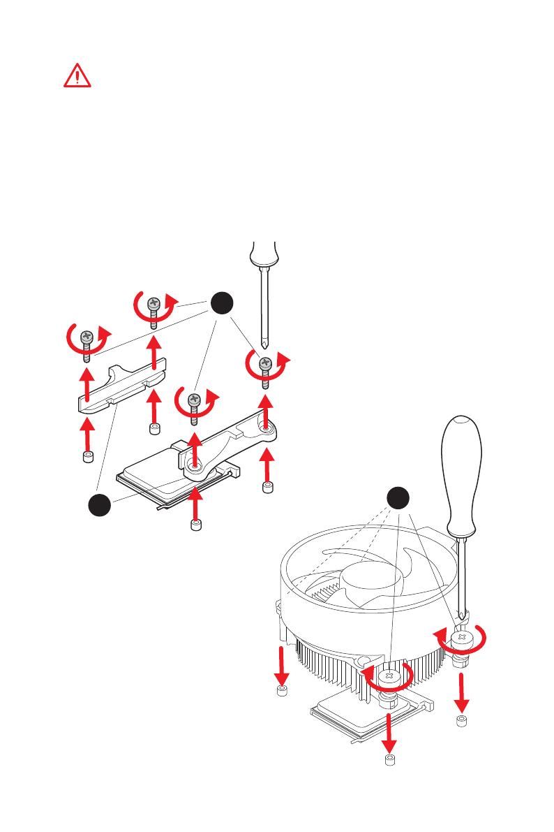
III
Quick Start
1
2
3
If you are installing the screw-type CPU heatsink, please follow the figure below
to remove the retention module first and then install the heatsink.
Wenn Sie einen CPU-Kühler mit Schraubenbefestigung einsetzen, folgen Sie bitte
den Anweisungen unten um das Retention-Modul zu entfernen und den Kühler zu
installieren.
Si vous voulez installer un ventirad pour processeur à vis, veuillez suivre les
instructions ci-dessous pour d’abord retirer le module de rétention puis installer le
ventirad.
В случае установки процессорного кулера с системой крепления на винтах,
следуйте указаниям на рисунке ниже для снятия пластикового модуля
крепления. Затем установите кулер.
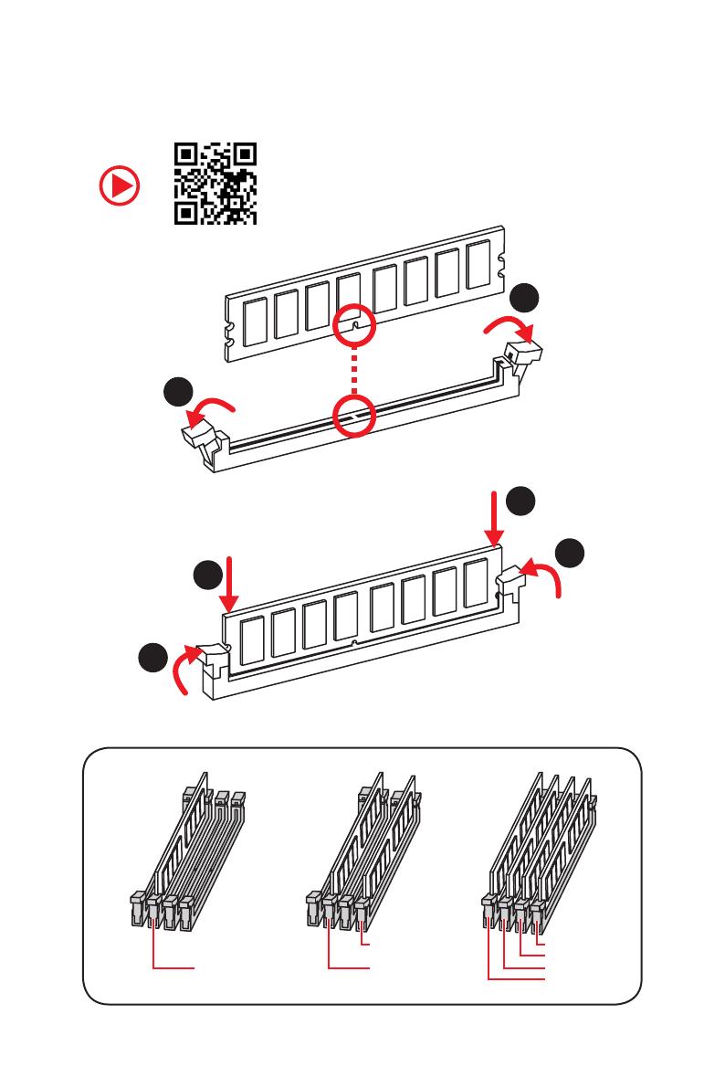
IV
Quick Start
Installing DDR4 memory/ Installation des DDR4-Speichers/
Installer une mémoire DDR4/ Установка памяти DDR4
DIMMB2 DIMMB2
DIMMB1
DIMMA2 DIMMA2 DIMMA2
DIMMA1
1
1
2
2
3
3
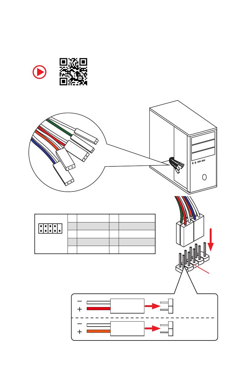
V
Quick Start
RESET SW
POWER SW
POWER LED+
POWER LED-
HDD LED
HDD LED
RESET SW
JFP1
HDD LED
HDD LED —
HDD LED +
POWER LED —
POWER LED +
POWER LED
Connecting the Front Panel Header/ Anschließen der
Frontpanel-Stiftleiste/ Connecter un connecteur du panneau
avant/ Подключение разъемов передней панели
1
2 10
9
JFP1
1 HDD LED + 2 Power LED +
3 HDD LED — 4 Power LED —
5 Reset Switch 6 Power Switch
7 Reset Switch 8 Power Switch
9 Reserved 10 No Pin
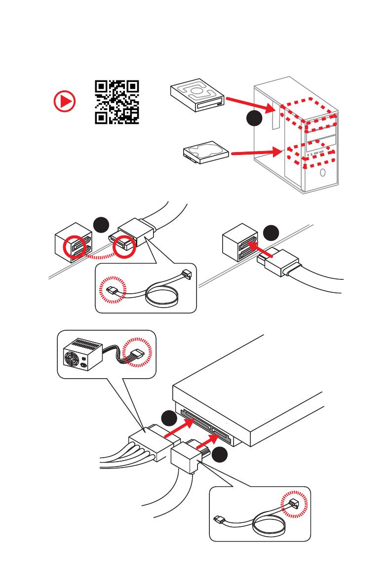
VII
Quick Start
1
2
3
4
5
Installing SATA Drives/ Installation der SATA-Laufwerke/
Installer le disque dur SATA/ Установка дисков SATA
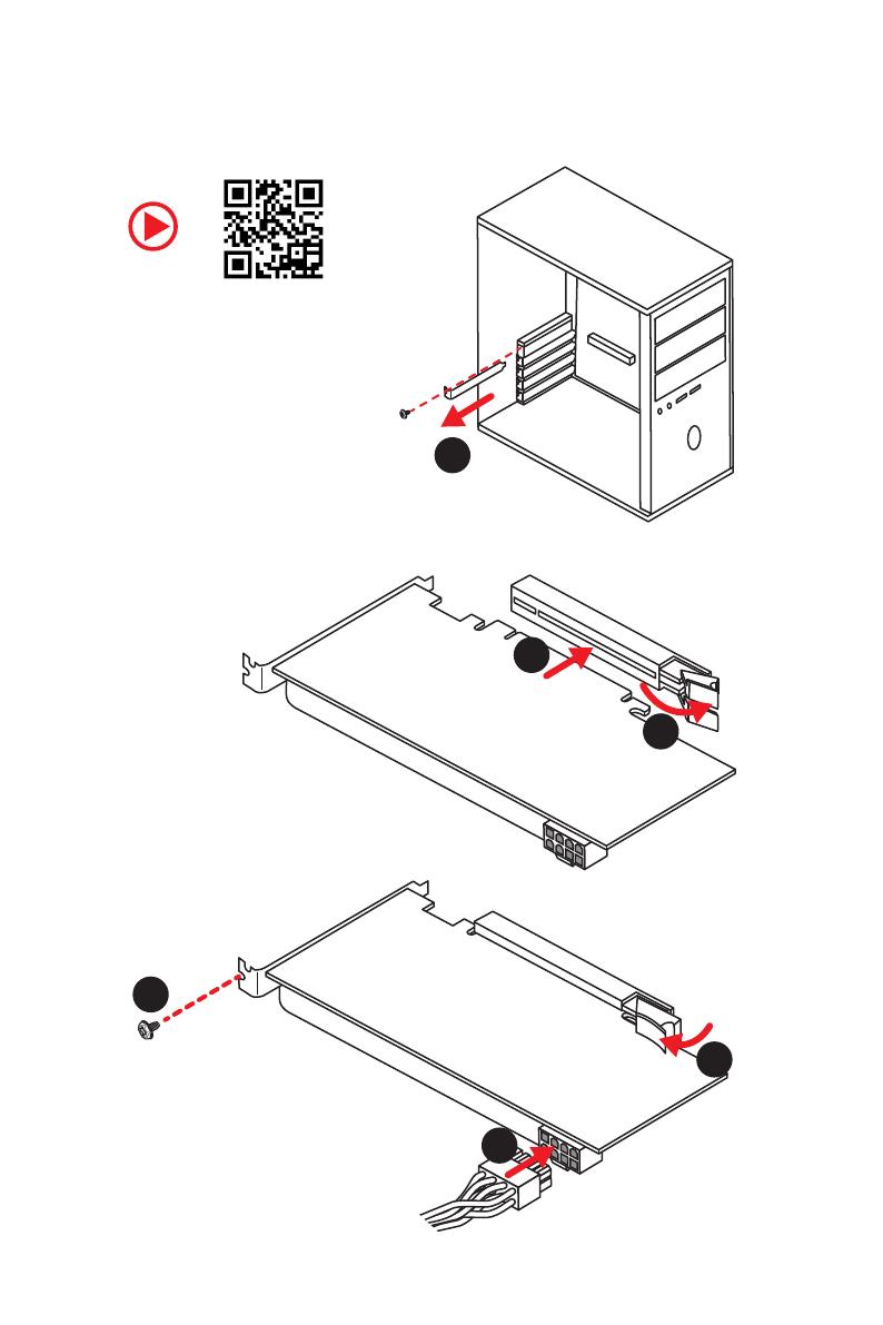
VIII
Quick Start
1
2
3
4
5
6
Installing a Graphics Card/ Einbau der Grafikkarte/ Installer
une carte graphique/ Установка дискретной видеокарты
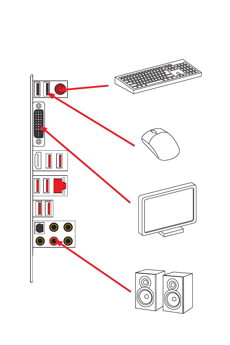
IX
Quick Start
Connecting Peripheral Devices/ Peripheriegeräte/
Connecter un périphérique anschliessen/ Подключение
периферийных устройств
Integrated Graphics Processing Unit (iGPU)
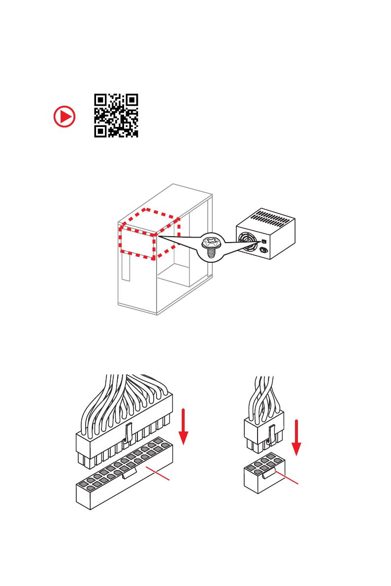
X
Quick Start
Connecting the Power Connectors/ Stromanschlüsse
anschliessen/ Connecter les câbles du module d’alimentation/
Подключение разъемов питания
ATX_PWR1
CPU_PWR1

XII
Quick Start
NOTE

4
Specifications
Continued from previous page
Multi-GPU
y 1st, 2nd and 3rd Gen AMD Ryzen™ Processors
Supports 3-Way AMD
®
CrossFire™ Technology
y Ryzen™ with Radeon™ Vega Graphics and 2nd Gen AMD
Ryzen™ with Radeon™ Graphics/ Athlon™ with Radeon™
Vega Graphics Processors
Supports 2-Way AMD
®
CrossFire™ Technology
LAN 1x Realtek
®
8111H Gigabit LAN controller
Storage
y 6x SATA 6Gb/s ports (from AMD
®
X470 Chipset)
y 2x M.2 ports (Key M)*
M2_1 slot (from AMD
®
processor) supports PCIe
3.0×4 (1st, 2nd and 3rd Gen AMD Ryzen™/ Ryzen™ with
Radeon™ Vega Graphics and 2nd Gen AMD Ryzen™ with
Radeon™ Graphics Processors) or PCIe 3.0×2 (Athlon™
with Radeon™ Vega Graphics Processors) 2242/ 2260
/2280/ 22110 storage devices
M2_2 slot (from AMD
®
X470 Chipset) supports PCIe 2.0
x4 and SATA 6Gb/s 2242/ 2260 /2280 storage devices
* SATA1 port will be unavailable when installing SATA M.2 SSD in M2_2 slot.
* PCI_E6 slot will be unavailable when installing PCIe M.2 SSD in M2_2 slot.
RAID
AMD
®
X470 Chipset
y Supports RAID 0, RAID 1 and RAID 10 for SATA storage
devices
USB
y ASMedia
®
ASM1143 Chipset
2x USB 3.2 Gen2 (SuperSpeed USB 10Gbps) Type-A
ports on the back panel
y AMD
®
X470 Chipset
4x USB 3.2 Gen1 (SuperSpeed USB) ports through the
internal USB connectors
6x USB 2.0 (High-speed USB) ports (2 Type-A ports on
the back panel, 4 ports available through the internal
USB connectors)
y AMD
®
CPU
4x USB 3.2 Gen1 (SuperSpeed USB) Type-A ports on the
back panel
Continued on next page

6
Specifications
Continued from previous page
I/O Controller NUVOTON NCT6795D Controller Chip
Hardware Monitor
y CPU/System temperature detection
y CPU/System fan speed detection
y CPU/System fan speed control
Form Factor
y ATX Form Factor
y 12 in. x 9.6 in. (30.5 cm x 24.4 cm)
BIOS Features
y 1x 256 Mb flash
y UEFI AMI BIOS
y ACPI 6.1, SM BIOS 2.8
y Multi-language
Software
y Drivers
y APP MANAGER
y COMMAND CENTER
y LIVE UPDATE 6
y MYSTIC LIGHT
y SUPER CHARGER
y GAMING APP
y RAMDISK
y X-BOOST
y SMART TOOL
y Nahimic Audio
y Open Broadcaster Software (OBS)
y Norton™ Internet Security Solution
y Google Chrome™, Google Toolbar, Google Drive
y CPU-Z MSI GAMING
Continued on next page
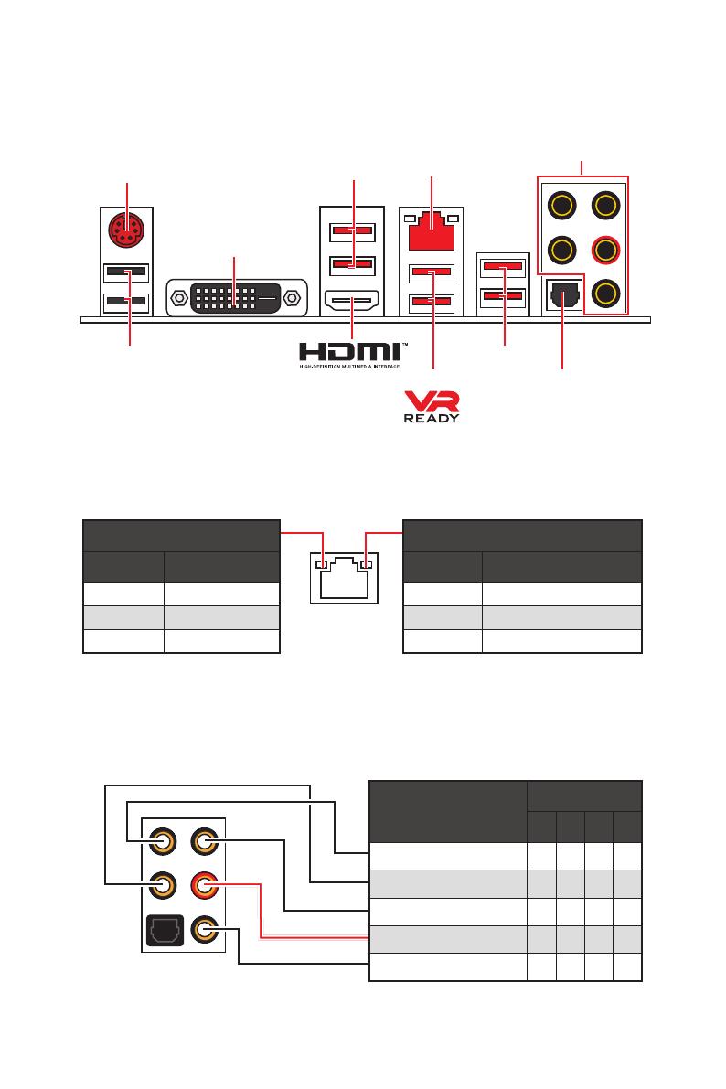
8
Rear I/O Panel
Audio Ports Configuration
Audio Ports
Channel
2 4 6 8
Center/ Subwoofer Out ● ●
Rear Speaker Out ● ● ●
Line-In/ Side Speaker Out ●
Line-Out/ Front Speaker Out ● ● ● ●
Mic In
(●: connected, Blank: empty)
Rear I/O Panel
LAN
USB 2.0
PS/2
Audio Ports
Optical S/PDIF-Out
USB 3.2 Gen1
USB 3.2 Gen1
USB 3.2 Gen2
Link/ Activity LED
Status Description
Off No link
Yellow Linked
Blinking Data activity
Speed LED
Status Description
Off 10 Mbps connection
Green 100 Mbps connection
Orange 1 Gbps connection
LAN Port LED Status Table
DVI-D
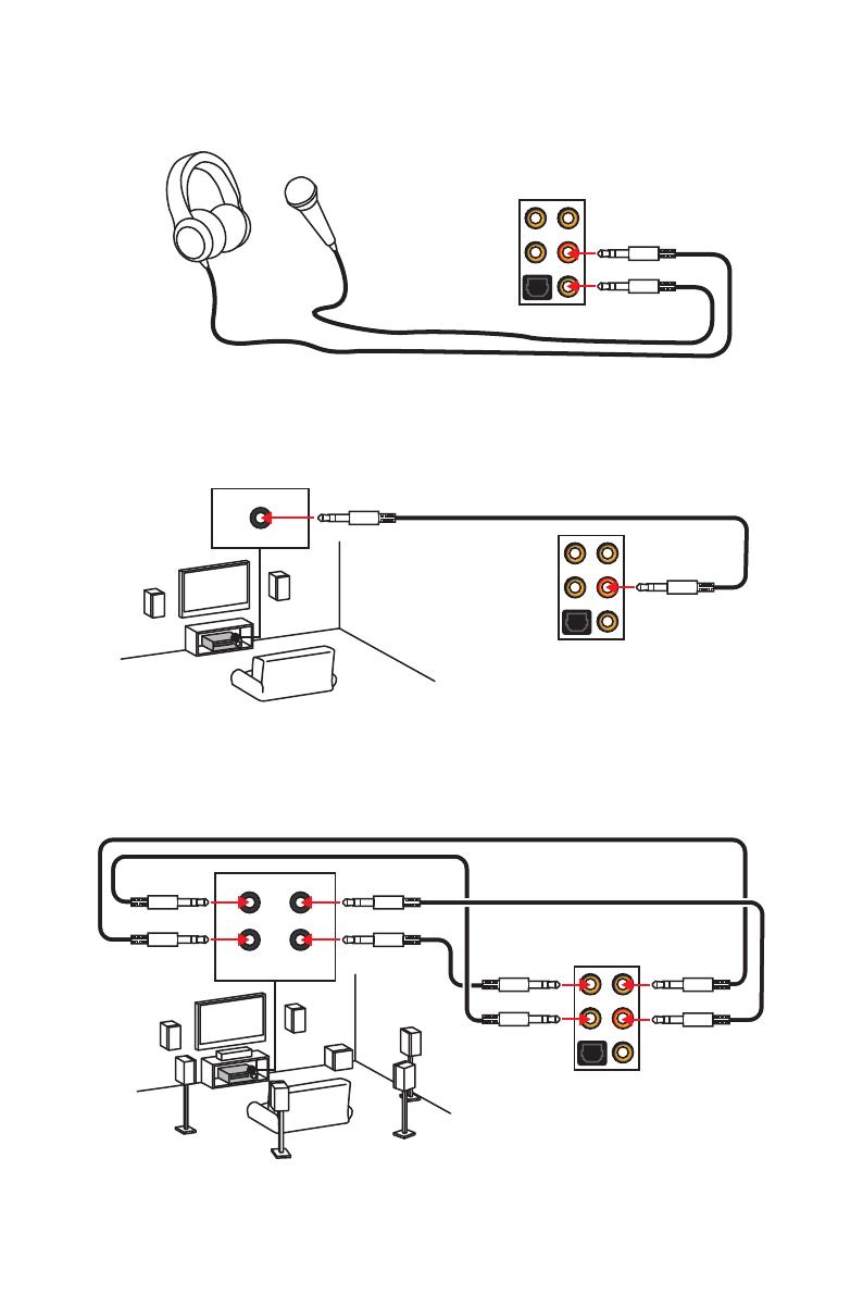
10
Rear I/O Panel
AUDIO INPUT
Rear Front
Side Center/
Subwoofer
Audio jacks to headphone and microphone diagram
Audio jacks to stereo speakers diagram
Audio jacks to 7.1-channel speakers diagram
AUDIO INPUT
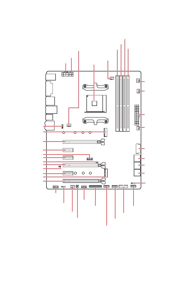
11
Overview of Components
Overview of Components
SATA▼3▲4
SATA▼1▲2
SATA▼5▲6
CPU_FAN1
JRGB1
JRGB2
PUMP_FAN1
PCI_E1
PCI_E2
PCI_E3
PCI_E4
PCI_E5
PCI_E6
JTPM1
CPU Socket
CPU_PWR1
CPU_PWR2
JBAT1
M2_2
M2_1
DIMMA1
SYS_FAN1
DIMMA2
DIMMB1
DIMMB2
JLPT1
JUSB1
JUSB2
JFP2
JFP1
JAUD1
ATX_PWR1
SYS_FAN3
SYS_FAN4
SYS_FAN2
Clear CMOS
JCOM1
JUSB4
JCI1
JUSB3
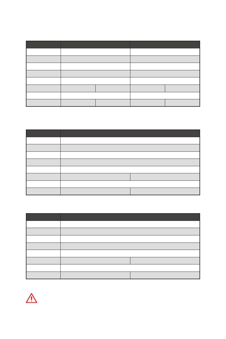
15
Overview of Components
PCIe bandwidth table
For 1st, 2nd and 3rd Gen AMD Ryzen™ Processors
Slot Single 2-Way
PCI_E1 (CPU) Gen 3.0 x 16* Gen 3.0 x 8*
PCI_E2 (PCH) Gen 2.0 x 1 Gen 2.0 x 1
PCI_E3 (PCH) Gen 2.0 x 1 Gen 2.0 x 1
PCI_E4 (CPU) ─ Gen 3.0 x 8*
PCI_E5 (PCH) Gen 2.0 x 1 Gen 2.0 x 1
PCI_E6 (PCH) Gen 2.0 x 4 ─ Gen 2.0 x 4 ─
M2_1 (CPU) Gen 3.0 x 4 Gen 3.0 x 4
M2_2 (PCH) ─ Gen 2.0 x 4 ─ Gen 2.0 x 4
(─: unavailable, *: graphics card)
For Ryzen™ with Radeon™ Vega Graphics and 2nd Gen AMD Ryzen™ with Radeon™
Graphics Processors
Slot Single
PCI_E1 (CPU) Gen 3.0 x 8*
PCI_E2 (PCH) Gen 2.0 x 1
PCI_E3 (PCH) Gen 2.0 x 1
PCI_E4 (CPU) ─
PCI_E5 (PCH) Gen 2.0 x 1
PCI_E6 (PCH) Gen 2.0 x 4 ─
M2_1 (CPU) Gen 3.0 x 4
M2_2 (PCH) ─ Gen 2.0 x 4
(─: unavailable, *: graphics card)
Athlon™ with Radeon™ Vega Graphics Processors
Slot Single
PCI_E1 (CPU) Gen 3.0 x 4*
PCI_E2 (PCH) Gen 2.0 x 1
PCI_E3 (PCH) Gen 2.0 x 1
PCI_E4 (CPU) ─
PCI_E5 (PCH) Gen 2.0 x 1
PCI_E6 (PCH) Gen 2.0 x 4 ─
M2_1 (CPU) Gen 3.0 x 2
M2_2 (PCH) ─ Gen 2.0 x 4
(─: unavailable, *: graphics card)
Important
PCI_E6 slot will be unavailable when installing PCIe M.2 SSD in M2_2 slot.
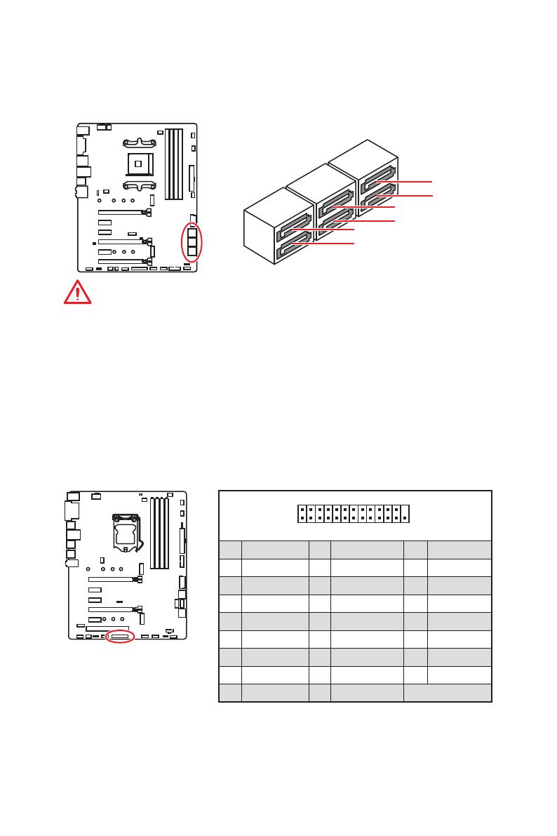
17
Overview of Components
SATA1~6: SATA 6Gb/s Connectors
These connectors are SATA 6Gb/s interface ports. Each connector can connect to one
SATA device.
SATA5
SATA3
SATA1
SATA6
SATA4
SATA2
Important
y
SATA1 port will be unavailable when installing SATA M.2 SSD in M2_2 slot.
y
Please do not fold the SATA cable at a 90-degree angle. Data loss may result during
transmission otherwise.
y
SATA cables have identical plugs on either sides of the cable. However, it is
recommended that the flat connector be connected to the motherboard for space
saving purposes.
1
2 26
25
1 RSTB# 2 AFD# 3 PRND0
4 ERR# 5 PRND1 6 PINIT#
7 PRND2 8 LPT_SLIN# 9 PRND3
10 Ground 11 PRND4 12 Ground
13 PRND5 14 Ground 15 PRND6
16 Ground 17 PRND7 18 Ground
19 ACK# 20 Ground 21 BUSY
22 Ground 23 PE 24 Ground
25 SLCT 26 No Pin
JLPT1: Parallel Port Connector
This connector allows you to connect the optional parallel port with bracket.
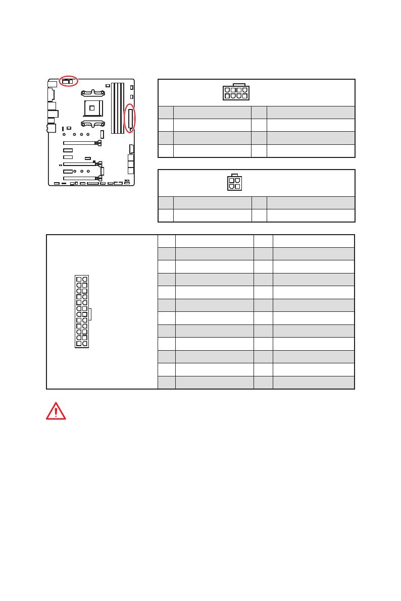
18
Overview of Components
24
131
12
ATX_PWR1
1 +3.3V 13 +3.3V
2 +3.3V 14 -12V
3 Ground 15 Ground
4 +5V 16 PS-ON#
5 Ground 17 Ground
6 +5V 18 Ground
7 Ground 19 Ground
8 PWR OK 20 Res
9 5VSB 21 +5V
10 +12V 22 +5V
11 +12V 23 +5V
12 +3.3V 24 Ground
5
4 1
8
CPU_PWR1
1 Ground 5 +12V
2 Ground 6 +12V
3 Ground 7 +12V
4 Ground 8 +12V
Important
Make sure that all the power cables are securely connected to a proper ATX power
supply to ensure stable operation of the motherboard.
CPU_PWR1, CPU_PWR2, ATX_PWR1: Power Connectors
These connectors allow you to connect an ATX power supply.
3
2 1
4
CPU_PWR2
1 Ground 3 +12V
2 Ground 4 +12V
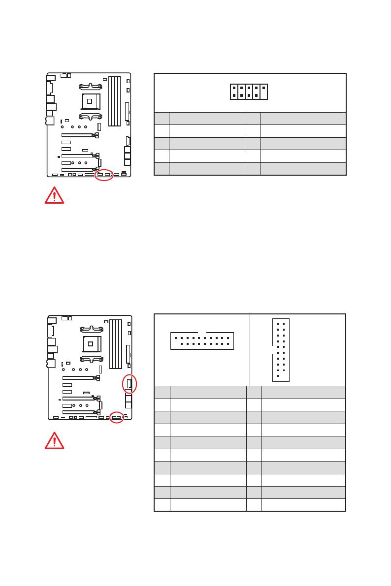
19
Overview of Components
JUSB3~4: USB 3.2 Gen1 Connectors
These connectors allow you to connect USB 3.2 Gen1 ports on the front panel.
Important
Note that the Power and
Ground pins must be
connected correctly to avoid
possible damage.
1 10
1120
JUSB3
1
10 11
20
JUSB4
1 Power 11 USB2.0+
2 USB3_RX_DN 12 USB2.0-
3 USB3_RX_DP 13 Ground
4 Ground 14 USB3_TX_C_DP
5 USB3_TX_C_DN 15 USB3_TX_C_DN
6 USB3_TX_C_DP 16 Ground
7 Ground 17 USB3_RX_DP
8 USB2.0- 18 USB3_RX_DN
9 USB2.0+ 19 Power
10 NC 20 No Pin
JUSB1~2: USB 2.0 Connectors
These connectors allow you to connect USB 2.0 ports on the front panel.
1
2 10
9
1 VCC 2 VCC
3 USB0- 4 USB1-
5 USB0+ 6 USB1+
7 Ground 8 Ground
9 No Pin 10 NC
Important
y
Note that the VCC and Ground pins must be connected correctly to avoid possible
damage.
y
In order to recharge your iPad,iPhone and iPod through USB ports, please install
MSI
®
SUPER CHARGER utility.
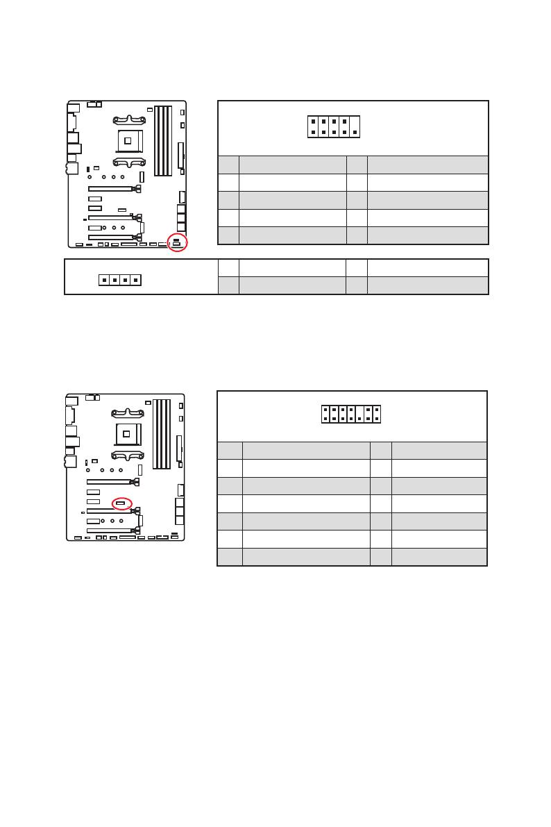
22
Overview of Components
1
2 14
13
1 LPC Clock 2 3V Standby power
3 LPC Reset 4 3.3V Power
5 LPC address & data pin0 6 Serial IRQ
7 LPC address & data pin1 8 5V Power
9 LPC address & data pin2 10 No Pin
11 LPC address & data pin3 12 Ground
13 LPC Frame 14 Ground
JTPM1: TPM Module Connector
This connector is for TPM (Trusted Platform Module). Please refer to the TPM security
platform manual for more details and usages.
JFP1, JFP2: Front Panel Connectors
These connectors connect to the switches and LEDs on the front panel.
1
2 10
9
JFP1
1 HDD LED + 2 Power LED +
3 HDD LED — 4 Power LED —
5 Reset Switch 6 Power Switch
7 Reset Switch 8 Power Switch
9 Reserved 10 No Pin
1
JFP2
1 Speaker — 2 Buzzer +
3 Buzzer — 4 Speaker +
- Manuals
- Brands
- MSI Manuals
- Motherboard
- X470 GAMING PLUS
- User manual
-
Contents
-
Table of Contents
-
Troubleshooting
-
Bookmarks
Quick Links
Unpacking
X470 GAMING PLUS
Thank you for buying the MSI
motherboard. Check to make sure
®
your motherboard box contains the following items. If something is missing, contact
your dealer as soon as possible.
Motherboard User
Drivers & Utilities
Guide
Disc
Motherboard
M.2 Screw x2
I/O Shield
SATA Cable x2
Case Badge
SATA Cable Labels
1
Unpacking
Related Manuals for MSI X470 GAMING PLUS
Summary of Contents for MSI X470 GAMING PLUS
-
Page 1: Unpacking
Unpacking X470 GAMING PLUS Thank you for buying the MSI motherboard. Check to make sure ® your motherboard box contains the following items. If something is missing, contact your dealer as soon as possible. Motherboard User Drivers & Utilities Guide…
-
Page 2: Safety Information
Safety Information y The components included in this package are prone to damage from electrostatic discharge (ESD). Please adhere to the following instructions to ensure successful computer assembly. y Ensure that all components are securely connected. Loose connections may cause the computer to not recognize a component or fail to start.
-
Page 3: Quick Start
Quick Start Preparing Tools and Components AM4 CPU ® Thermal Paste CPU Fan DDR4 Memory Power Supply Unit Chassis SATA Hard Disk Drive Graphics Card SATA DVD Drive A Package of Screws Phillips Screwdriver Quick Start…
-
Page 4: Installing A Processor
Installing a Processor https://youtu.be/Xv89nhFk1vc CPU_FAN1 Quick Start…
-
Page 5
Important If you are installing the screw-type CPU heatsink, please follow the figure below to remove the retention module first and then install the heatsink. Quick Start… -
Page 6: Installing Ddr4 Memory
Installing DDR4 memory http://youtu.be/T03aDrJPyQs DIMMB2 DIMMB2 DIMMB1 DIMMA2 DIMMA2 DIMMA2 DIMMA1 Quick Start…
-
Page 7: Connecting The Front Panel Header
Connecting the Front Panel Header http://youtu.be/DPELIdVNZUI HDD LED + Power LED + HDD LED — Power LED — Reset Switch Power Switch Reset Switch Power Switch JFP1 Reserved No Pin JFP1 HDD LED — HDD LED HDD LED + POWER LED — POWER LED POWER LED + Quick Start…
-
Page 8: Installing The Motherboard
Installing the Motherboard Quick Start…
-
Page 9: Installing Sata Drives
Installing SATA Drives http://youtu.be/RZsMpqxythc Quick Start…
-
Page 10: Installing A Graphics Card
Installing a Graphics Card http://youtu.be/mG0GZpr9w_A Quick Start…
-
Page 11: Connecting Peripheral Devices
Connecting Peripheral Devices Quick Start…
-
Page 12: Connecting The Power Connectors
Connecting the Power Connectors http://youtu.be/gkDYyR_83I4 ATX_PWR1 CPU_PWR1 CPU_PWR2 Quick Start…
-
Page 13: Power On
Power On Quick Start…
-
Page 14: Table Of Contents
Contents Unpacking ………………….1 Safety Information ………………..2 Quick Start ………………….3 Preparing Tools and Components …………….3 Installing a Processor ………………… 4 Installing DDR4 memory ………………6 Connecting the Front Panel Header …………… 7 Installing the Motherboard ………………8 Installing SATA Drives…………………
-
Page 15
CLR_CMOS1: Clear CMOS Button ……………. 40 BIOS Setup ………………….41 Entering BIOS Setup ………………… 41 Resetting BIOS …………………. 42 Updating BIOS ………………….. 42 System Status ………………….. 43 Advanced ………………….. 44 OC …………………….. 50 M-FLASH ………………….55 Security ……………………. 56 Boot ……………………58 Save &… -
Page 16
Contents… -
Page 17: Specifications
Supports ECC UDIMM memory * A-series/ Athlon™ processors support up to 2400 MHz. And the supporting frequency of memory varies with installed processor. Please refer www.msi.com for more information on compatible memory. y 2x PCIe 3.0 x16 slots (PCIE_1, PCIE_4) ƒ…
-
Page 18
Continued from previous page 1x Realtek 8111H Gigabit LAN controller ® y 6x SATA 6Gb/s ports (from AMD X470 Chipset) ® y 2x M.2 ports (Key M)* ƒ M2_1 slot (from AMD processor) supports PCIe 3.0 ® x4 (1st, 2nd and 3rd Gen AMD Ryzen™/ Ryzen™ with Radeon™… -
Page 19
Continued from previous page y 1x PS/2 keyboard/ mouse combo port y 2x USB 2.0 Type-A ports y 1x DVI-D port y 1x HDMI™ 1.4 port Back Panel y 4x USB 3.1 Gen1 Type-A ports Connectors y 1x LAN (RJ45) port y 2x USB 3.1 Gen2 Type-A ports y 5x OFC audio jacks y 1x Optical S/PDIF OUT connector… -
Page 20
GAMING APP Software y RAMDISK y X-BOOST y SMART TOOL y Nahimic Audio y Open Broadcaster Software (OBS) y Norton™ Internet Security Solution y Google Chrome™, Google Toolbar, Google Drive y CPU-Z MSI GAMING Continued on next page Specifications… -
Page 21
Continued from previous page y Audio ƒ Audio Boost ƒ Voice Boost ƒ Nahimic 2.5 y Storage ƒ Turbo M.2 y Fan ƒ Pump Fan ƒ Smart Fan Control y LED ƒ Mystic Light ƒ Mystic Light Extension ƒ Mystic light SYNC ƒ… -
Page 22: Block Diagram
Block Diagram HDMI DVI-D 2 Channel DDR4 Memory 1 x M.2 PCI Express Bus PCIex4 4 x USB 3.1 Gen1 Realtek ALC892 Audio Jacks NV6795 Super I/O P/S2 Mouse / Keyboard PCIe x4 slot Switch PCIe x1 slot 1 x M.2 PCIe x1 slot Switch PCIe x1 slot…
-
Page 23: Rear I/O Panel
Rear I/O Panel Audio Ports USB 3.1 Gen1 PS/2 DVI-D USB 2.0 USB 3.1 Gen2 Optical S/PDIF-Out USB 3.1 Gen1 LAN Port LED Status Table Link/ Activity LED Speed LED Status Description Status Description No link 10 Mbps connection Yellow Linked Green 100 Mbps connection…
-
Page 24: Realtek Hd Audio Manager
Realtek HD Audio Manager After installing the Realtek HD Audio driver, the Realtek HD Audio Manager icon will appear in the system tray. Double click on the icon to launch. Device Selection Advanced Settings Jack Status Application Enhancement Main Volume Connector Settings Profiles…
-
Page 25
Audio jacks to headphone and microphone diagram Audio jacks to stereo speakers diagram AUDIO INPUT Audio jacks to 7.1-channel speakers diagram AUDIO INPUT Rear Front Side Center/ Subwoofer Rear I/O Panel… -
Page 26: Overview Of Components
Overview of Components DIMMB1 DIMMA2 DIMMB2 DIMMA1 SYS_FAN1 CPU_PWR2 CPU_FAN1 CPU_PWR1 CPU Socket PUMP_FAN1 SYS_FAN3 ATX_PWR1 JRGB2 SYS_FAN4 M2_1 PCI_E1 JUSB4 PCI_E2 JTPM1 PCI_E3 SATA▼5▲6 JCI1 PCI_E4 SATA▼3▲4 JBAT1 PCI_E5 SATA▼1▲2 M2_2 PCI_E6 JFP2 JAUD1 JCOM1 JRGB1 JLPT1 JFP1 SYS_FAN2 JUSB3 Clear CMOS JUSB2…
-
Page 27
Component Contents Port Name Port Type Page CLR_CMOS1 Clear CMOS Button CPU_FAN1, PUMP_FAN1, Fan Connectors SYS_FAN1~4 CPU_PWR1, CPU_PWR2, Power Connectors ATX_PWR1 CPU Socket AM4 CPU Socket DIMMA1, DIMMA2, DIMM Slots DIMMB1, DIMMB2 JAUD1 Front Audio Connector JBAT1 Clear CMOS (Reset BIOS) Jumper JCI1 Chassis Intrusion Connector JCOM1… -
Page 28: Cpu Socket
This motherboard is designed to support overclocking. Before attempting to overclock, please make sure that all other system components can tolerate overclocking. Any attempt to operate beyond product specifications is not recommended. MSI does not guarantee the damages or risks caused by inadequate ®…
-
Page 29: Dimm Slots
Due to AM4 CPU/memory controller official specification limitation, the frequency of memory modules may operate lower than the marked value under the default state. Please refer www.msi.com for more information on compatible memory. Overview of Components…
-
Page 30: Pci_E1~6: Pcie Expansion Slots
Important If you install a large and heavy graphics card, you need to use a tool such as MSI Gaming Series Graphics Card Bolster to support its weight to prevent deformation of the slot. For a single PCIe x16 expansion card installation with optimum performance, using the PCI_E1 slot is recommended.
-
Page 31
PCIe bandwidth table For Ryzen™ Desktop processors Slot Single 2-Way PCI_E1 (CPU) Gen 3.0 x 16* Gen 3.0 x 8* PCI_E2 (PCH) Gen 2.0 x 1 Gen 2.0 x 1 PCI_E3 (PCH) Gen 2.0 x 1 Gen 2.0 x 1 ─… -
Page 32: M2_1~2: M.2 Slots (Key M)
M2_1~2: M.2 Slots (Key M) Important SATA1 port will be unavailable when installing SATA M.2 SSD in M2_2 slot. PCI_E6 slot will be unavailable when installing PCIe M.2 SSD in M2_2 slot. M2_1 M2_1 slot only supports PCIe mode. M2_2 Video Demonstration Watch the video to learn how to Install M.2 SSD.
-
Page 33: Sata1~6: Sata 6Gb/S Connectors
SATA1~6: SATA 6Gb/s Connectors These connectors are SATA 6Gb/s interface ports. Each connector can connect to one SATA device. SATA6 SATA5 SATA4 SATA3 SATA2 SATA1 Important SATA1 port will be unavailable when installing SATA M.2 SSD in M2_2 slot. Please do not fold the SATA cable at a 90-degree angle. Data loss may result during transmission otherwise.
-
Page 34: Cpu_Pwr1, Cpu_Pwr2, Atx_Pwr1: Power Connectors
CPU_PWR1, CPU_PWR2, ATX_PWR1: Power Connectors These connectors allow you to connect an ATX power supply. CPU_PWR1 Ground +12V Ground +12V Ground +12V Ground +12V CPU_PWR2 Ground +12V Ground +12V +3.3V +3.3V +3.3V -12V Ground Ground PS-ON# Ground Ground Ground ATX_PWR1 Ground Ground PWR OK…
-
Page 35: Jusb1~2: Usb 2.0 Connectors
JUSB1~2: USB 2.0 Connectors These connectors allow you to connect USB 2.0 ports on the front panel. USB0- USB1- USB0+ USB1+ Ground Ground No Pin Important Note that the VCC and Ground pins must be connected correctly to avoid possible damage.
-
Page 36: Cpu_Fan1, Pump_Fan1, Sys_Fan1~4: Fan Connectors
CPU_FAN1, PUMP_FAN1, SYS_FAN1~4: Fan Connectors Fan connectors can be classified as PWM (Pulse Width Modulation) Mode or DC Mode. PWM Mode fan connectors provide constant 12V output and adjust fan speed with speed control signal. DC Mode fan connectors control fan speed by changing voltage.
-
Page 37: Jaud1: Front Audio Connector
JAUD1: Front Audio Connector This connector allows you to connect audio jacks on the front panel. MIC L Ground MIC R Head Phone R MIC Detection SENSE_SEND No Pin Head Phone L Head Phone Detection JCI1: Chassis Intrusion Connector This connector allows you to connect the chassis intrusion switch cable. Normal Trigger the chassis intrusion event…
-
Page 38: Jfp1, Jfp2: Front Panel Connectors
JFP1, JFP2: Front Panel Connectors These connectors connect to the switches and LEDs on the front panel. JFP1 HDD LED + Power LED + HDD LED — Power LED — Reset Switch Power Switch Reset Switch Power Switch Reserved No Pin Speaker — Buzzer + JFP2…
-
Page 39: Jcom1: Serial Port Connector
Please keeping the LED strip shorter than 2 meters to prevent dimming. Always turn off the power supply and unplug the power cord from the power outlet before installing or removing the RGB LED strip. Please use MSI’ s software to control the extended LED strip. Overview of Components…
-
Page 40: Jbat1: Clear Cmos (Reset Bios) Jumper
JBAT1: Clear CMOS (Reset BIOS) Jumper There is CMOS memory onboard that is external powered from a battery located on the motherboard to save system configuration data. If you want to clear the system configuration, set the jumpers to clear the CMOS memory. Keep Data Clear CMOS/ Reset BIOS…
-
Page 41: Bios Setup
BIOS Setup The default settings offer the optimal performance for system stability in normal conditions. You should always keep the default settings to avoid possible system damage or failure booting unless you are familiar with BIOS. Important BIOS items are continuously update for better system performance. Therefore, the description may be slightly different from the latest BIOS and should be for reference only.
-
Page 42: Resetting Bios
Updating BIOS Updating BIOS with M-FLASH Before updating: Please download the latest BIOS file that matches your motherboard model from MSI website. And then save the BIOS file into the USB flash drive. Updating BIOS: 1. Insert the USB flash drive that contains the update file into the computer.
-
Page 43: System Status
System Status f System Language [English] Choose the BIOS default language. f System Date Sets the system date. Use tab key to switch between date elements. The format is <day> <month> <date> <year>. <day> Day of the week, from Sun to Sat, determined by BIOS. Read-only. <month>…
-
Page 44: Advanced
[Disabled] Disables this function. fPCI_E1 Lanes Configuration PCIe lanes configuration is for MSI M.2 Xpander / MSI M.2 Xpander-Z / Other M.2 PCIe storage card. The options in this item will vary with the installed processor. f ACPI Settings Sets ACPI parameters of onboard power LED behaviors. Press Enter to enter the sub- menu.
-
Page 45
fPower LED [Blinking] Sets shining behaviors of the onboard Power LED. [Dual Color] The power LED turns to another color to indicate the S3 state. [Blinking] The power LED blinks to indicate the S3 state. f Integrated Peripherals Sets integrated peripherals’ parameters, such as LAN, HDD, USB and audio. Press Enter to enter the sub-menu. -
Page 46
f Integrated Graphics Configuration (optional) Adjusts integrated graphics settings for optimum system. Press Enter to enter the sub-menu. fInitiate Graphic Adapter [PEG] (optional) Selects a graphics device as the primary boot device. [IGD] Integrated Graphics Display. [PEG] PCI-Express Graphics Device. fIntegrated Graphics [Auto] (optional) If set to Force, BIOS will enable the integrated graphics controller. -
Page 47
fParallel (LPT) Port Settings [Auto] Sets parallel port (LPT). If set to Auto, BIOS will optimize the IRQ automatically or you can set it manually. fDevice Mode [STD Printer Mode] Selects an operating mode for parallel port. [STD Printer Mode] Printer port mode [SPP] Standard Parallel Port mode… -
Page 48
fGOP Information Shows the onboard Graphics Output Protocol (GOP) information. Press Enter to enter the sub-menu. This sub-menu will appear when BIOS UEFI/CSM Mode sets to UEFI. fSecure Boot Sets the Windows secure boot to prevent the unauthorized accessing. Press Enter to enter the sub-menu. -
Page 49
fResume From S3/S4/S5 by PS/2 Keyboard [Disabled] Enables or disables the system wake up by PS/2 keyboard. [Any Key] Enables the system to be awakened from S3/ S4/ S5 state when activity of any key on PS/2 keyboard is detected. [Hot Key] Enables the system to be awakened from S3/ S4/ S5 state when activity of hot key on PS/2 keyboard is detected. -
Page 50
Important Overclocking your PC manually is only recommended for advanced users. Overclocking is not guaranteed, and if done improperly, it could void your warranty or severely damage your hardware. If you are unfamiliar with overclocking, we advise you to use GAME BOOST function for easy overclocking. -
Page 51
f DRAM Frequency [Auto] Sets the DRAM frequency. Please note the overclocking behavior is not guaranteed. f Adjusted DRAM Frequency Shows the adjusted DRAM frequency. Read-only. f Memory Try It ! [Disabled] It can improve memory compatibility or performance by choosing optimized memory preset. -
Page 52
fCPU NB/SoC Under Voltage Protection [Auto] Sets the voltage limit for NB/ SoC under-voltage protection. If set to Auto, BIOS will configure this setting automatically. Higher voltage provides less protection and may damage the system. fCPU NB/SoC Over Current Protection [Auto] Sets the current limit for CPU NB/ SoC over-current protection. -
Page 53
fSimultaneous Multi-Threading [Enabled] (optional) Enables/ disables the AMD Simultaneous Multi-Threading. This item appears when the installed CPU supports this technology. fOpcache Control [Auto] (optional) Enables/ disables Opcache. Opcache stores recent decode instruction to save the decoding time when the instruction is repeated. And it may increase the CPU performance and reduce the power consumption slightly. -
Page 54
fCPU VDD_SoC Current Optimization [Auto] (optional) Sets the currents of CPU VDD and SoC. If set to Auto, BIOS will configure this setting automatically. [Auto] This setting will be configured automatically by BIOS. [Custom Setting] Allows you to set the currents manually. BIOS Setup… -
Page 55: M-Flash
M-FLASH provides the way to update BIOS with a USB flash drive. Please download the latest BIOS file that matches your motherboard model from MSI website, save the BIOS file into your USB flash drive. And then follow the steps below to update BIOS.
-
Page 56: Security
Security f Administrator Password Sets administrator password for system security. User has full rights to change the BIOS items with administrator password. After setting the administrator password, the state of this item will show Installed. f User Password Sets User Password for system security. User has limited rights to change the BIOS items with user password.
-
Page 57
you can enter the setup and OS without authorization. f Trusted Computing Sets TPM (Trusted Platform Module) function. fSecurity Device Support [Disabled] Enables or disables the TPM function to build the endorsement key for accessing the system. fAMD fTPM switch [AMD CPU fTPM] Selects TPM device. -
Page 58: Boot
Boot The Boot Menu allows you to specify the priority of boot devices. f Full Screen Logo Display [Enabled] Enables or disables to show the full screen logo while system POST. [Enabled] Shows the logo in full screen. [Disabled] Shows the POST messages. f Bootup NumLock State [On] Select the keyboard NumLock state upon bootup.
-
Page 59: Save & Exit
Save & Exit f Discard Changes and Exit Exit BIOS setup without saving any change. f Save Changes and Reboot Save all changes and reboot the system. f Save Changes Save current changes. f Discard Changes Discard all changes and restore to the previous values. f Restore Defaults Restore or load all default values.
-
Page 60: Software Description
7. Follow the instructions on the screen to install Windows ® Installing Drivers 1. Start up your computer in Windows ® 2. Insert MSI Driver Disc into your optical drive. ® 3. The installer will automatically appear and it will find and list all necessary drivers.
-
Page 61: App Manager
Motherboard Information — shows the model name of motherboard. y Total Install/ Update — click on this tab to update/ install all the applications. Important Please note that, once you uninstall the APP MANAGER, all the MSI applications and software will be uninstalled simultaneously. Software Description…
-
Page 62: Live Update 6
LIVE UPDATE 6 LIVE UPDATE 6 is an application for the MSI system to scan and download the latest ® drivers, BIOS and utilities. With LIVE UPDATE 6, you don’ t need to search the drivers on websites, and don’ t need to know the models of motherboard and graphics cards.
-
Page 63
1. Select the Live Update tab. 2. Choose Automatic scan, system will automatically scan all the items and search for the latest update files. Or you can choose Manual scan and select the items you wish to scan. 3. Click the Scan button at the bottom. It may take several moments to complete the process. -
Page 64: Command Center
COMMAND CENTER COMMAND CENTER is an user-friendly software and exclusively developed by MSI, helping users to adjust system settings and monitor status under OS. With the help of COMMAND CENTER, making it possible to achieve easier and efficient monitoring process and adjustments than that under BIOS. In addition, the COMMAND CENTER can be a server for mobile remote control application.
-
Page 65
CPU Fan CPU Fan control panel provides Smart mode and Manual Mode. You can switch the control mode by clicking the Smart Mode and Manual Mode buttons on the top of the CPU Fan control panel. y Manual Mode — allows you to manually control the CPU fan speed by percentage. -
Page 66
Option Buttons — Advanced When click the Advanced button, The Voltage, Fan and DRAM icons will appear. y Voltage — allows you to adjust advanced voltage values of CPU and chipset. y Fan — allows you to control the system fans speed. y DRAM — shows the current Advanced DRAM parameters, and allows you to change the settings by selecting values from the drop-down menu on the right hand side. -
Page 67
7. Find the IP address on the SoftAP Management Setting area, and enter the IP address on your MSI COMMAND CENTER APP to link your system. ® 8. Press Refresh on the MSI COMMAND CENTER APP to verify that monitoring and ® OC functions are working properly. -
Page 68: Gaming App
3. Connect your android device and motherboard to the same local area network. 4. Run MSI GAMING APP APP on your android device. ® 5. Press the Remote Control Setting icon on the MSI GAMING APP APP to find the ® paired device Name you set in the Remote Control Setting panel.
-
Page 69
OSD Setting Panel Use the OSD setting panel to specify information within on-screen display (OSD). y Apply Button — applies above settings to OSD. Eye Rest Eye Rest allows you to optimize the display on your monitor. y EyeRest — reduces blue-light of your LED backlit screen, in order to protect your eyes. -
Page 70
ƒ Login Keys — provides hotkey login function. ƒ MSI Smart Keys — allows you to define hotkeys for MSI Smart Keys. y Hotkey Manager — allows you to create, edit and delete hotkeys. y Current Hotkeys — shows all existing hotkeys. -
Page 71
Mouse Master Mouse Master provides mouse macro function. You can also use it to change DPI of your mouse. DPI Setting Delay Time Default Button Macro Hot Key DPI Hot Key Mouse Action Action List Test Area Edit Buttons Clear Button Load Button Save Button y Delay Time — allows you to apply a delay time in mouse macro. -
Page 72
VR Ready It will optimize the performance of your system to ensure everything is VR Ready. VR ON/ OFF Applications y VR ON/ OFF -enables or disables VR settings. y Applications — appears when you turn on the VR support. It allows you to close some applications to optimize the system for better VR experience. -
Page 73: X-Boost
X-BOOST The MSI X-BOOST allows you to select the system performance mode to meet your current system environment or support faster storage access speed for your external storage or memory cards. Easy In Easy page, you can select one system performance mode to meet the current system environment.
-
Page 74
STORAGE BOOST — supports faster access speed of storage device. Important Please note that you can only select one mode at a time from Easy or Advance page as MSI X-BOOST function. The improved transfer rate/ access speed will vary with the USB/ storage device. Software Description… -
Page 75: Mystic Light
MYSTIC LIGHT MYSTIC LIGHT is an application allows you to control LED lights of MSI products. For some earlier products, you can go to product download page to download the applicable LED control software. Main Screen The Main screen is used to configure what devices need to be synchronized and LED light effect options.
-
Page 76
You can also change settings for single device. To do that, you have to click the sync bubble twice and make it turn gray as below. Then you go to DEVICE SETTING and click SETTING. click SETTING After that, the computer will open a different windows and you can modify LED there individually. -
Page 77
If you wish to customize multiple device at the same time, click the bubble until it turn red like below. Use the LIGHT EFFECT & COLOR section on the main menu to make change. Note: Currently only GTX 1080 Ti Lightning -/X/Z and GTX 1080 Ti Gaming -/X Trio supports Light Speed/Brightness and no device supports Direction. -
Page 78
Motherboard Screen The motherboard screen is used to configure the LED light effect of the motherboard. SYNC ALL Return Button Motherboard ON/ OFF ALL LED Name PROFILE Live Preview LED AREA Light Effect Apply Button Options Save Button Note: The motherboard picture and name may vary according to different models. y Return Button — returns to the main screen. -
Page 79: Mystic Light Party
This section allows you to control LED across different platform. The pre-requisite is that the platforms should all be connected within the same local network. Refer to device support list web page. https://www.msi.com/Landing/Mystic-Light-Party. PARTY Upon clicking PARTY, this window would pop out. On your master platform, click create a host group.
-
Page 80: Joining Group
The group has been created. The other computers in the same local network are able to join the group with MYSTIC LIGHT software. DELETE Group Button Control Group Button Invitation Status Indicator Group In/Out Status ƒ DELETE Group Button — deletes the group. ƒ…
-
Page 81: Group Control Panel
Group Control Panel If everything is set up properly, you can see your slave platform on master platform MYSTIC LIGHT PARTY window. APPLY button Light Effect Options Invite Button Color Selection Group Members Icon At the panel below, you may apply different LED settings and color to the selected platform.
-
Page 82: Inviting Member
y Invite Button — enters the INVITE screen. y Light Effect Options — allow you to customize lighting effect. Always on Breathe Random Flash Double flash Marquee Rainbow Sound beat y Color Selection — allows you to change color. Inviting Member Click the Invite button in the Group Control Panel to enter the INVITE screen.
-
Page 83: Smart Tool
SMART TOOL SMART TOOL is a convenient tool that can help you to create your Windows installation USB flash drive, and it can also create a super RAID. Main menu After installing and activating SMART TOOL, it will display a main menu for you to choose Smart Tool or SUPER RAID.
-
Page 84
SUPER RAID This utility allows you to create a super RAID in Windows system. To create a super RAID: 1. Use checkboxs to select the disks you want included in your RAID. 2. Choose Speed Up or Backup for RAID type. y Speed Up = RAID0 y Backup = RAID1 3. -
Page 85: Nahimic 2.5
HD Audio Recorder2 and Sound Tracker. Installation and Update Nahimic 2.5 is included in the audio driver. If you need to install it or update it, please use the Driver Disc with your motherboard or download the driver from MSI’ s official website. Audio Tab From this tab, you can access all of Nahimic 2.5’…
-
Page 86
˜ Music — expands the stereo for a wider sound stage. Each audio effect can be disabled by clicking on it. ƒ Reverb — increases the feeling of space by applying different types of reverbs corresponding to different room sizes. ƒ… -
Page 87
Microphone Tab From this tab, you can access all of Nahimic 2.5’ s microphone effects and settings. Microphone Loopback Device properties Display & Volume Microphone Effects Reset Button Mute On/Off Button y Display & Volume — displays the type of audio recording device currently being used as input, as well as its current volume. -
Page 88
Audio Launchpad effects Control page Properties y Audio Launchpad effects — allows streamers to use prerecorded sounds during a livestream. These sounds can also be heard by viewers. This tool will allow you to create your true audio identity. That way, your livestreams will be more personal and animated. -
Page 89
Sound Tracker The Sound Tracker is an FPS oriented feature that provides a visual indication localizing the source of the strongest sound while in a game. The Sound Tracker captions the 5.1 and 7.1 sound streams processed by your audio system, and is displayed in all applications and games using DirectX 9, 9c, 10 and 11. -
Page 90: Amd Raid Configuration
AMD RAID Configuration The following are the RAID levels supported by RAIDXpert2. RAID 0 (Striping) breaks the data into blocks which are written to separate hard drives. Spreading the hard drive I/O load across independent channels greatly improves I/O performance. RAID 1 (Mirroring) provides data redundancy by mirroring data between the hard drives and provides enhanced read performance.
-
Page 91: Initializing Disks
Initializing Disks New disks and legacy disks must be initialized before they can be used to create an AMD-RAID array. Initialization writes AMD-RAID configuration information (metadata) to a disk. Important If a disk is part of an AMD-RAID array, the disk cannot be selected for initialization. To initial the disk anyway, delete the AMD-RAID array.
-
Page 92: Creating Arrays
Creating Arrays Arrays can be created after the disks are initialized. Important For redundant arrays, the Create process is not started until after the operating system and AMD-RAID OS drivers have been installed and the system has booted to the operating system. However, the arrays are immediately available to use for either a bootable array or a data array.
-
Page 93: Deleting Arrays
Deleting Arrays Important Deleting an array permanently destroys all data that is on the array. This action cannot be undone and it is very unlikely that the data can be recovered. Do not delete the first array listed in the Arrays section, if it is the AMD-RAID bootable array.
-
Page 94: Installing Raid Driver
2. When prompted, insert the USB flash drive with AMD RAID Drivers and then click Browse. ƒ To make an AMD RAID Drivers USB flash drive. Insert the MSI Driver Disc into the optical drive. Copy all the contents in \\Storage\AMD\Packages\Drivers\SBDrv\ 3.
-
Page 95: Troubleshooting
Troubleshooting Lost BIOS password Before sending the motherboard for RMA repair, try to go over troubleshooting y Clear the CMOS, but that will cause guide first to see if your got similar you to lose all customized settings in the symptoms as mentioned below.
-
Page 96
The point of contact for regulatory matters is MSI, recycling and disposing of their end-of-life products. MSI-NL Eindhoven 5706 5692 ER Son. y Visit the MSI website and locate a nearby distributor B급 기기 (가정용 방송통신기자재) for further recycling information. -
Page 97
MSI will comply with the product take entregar a una empresa autorizada para la recogida de back requirements at the end of life of MSI-branded estos residuos. -
Page 98
MSI si adeguerà a tale Direttiva ritirando tutti i prodotti marchiati MSI che sono stati venduti all’interno dell’Unione Europea alla fine del loro ciclo di vita. -
Page 99
Micro-Star Int’ l Co., Ltd. All other marks and names mentioned may be trademarks of their respective owners. No warranty as to accuracy or completeness is expressed or implied. MSI reserves the right to make changes to this document without prior notice. Technical Support…
Материнская плата MSI X470 GAMING PLUS MAX, SocketAM4, AMD X470, ATX, Ret
Нет в наличии
Последний раз товар был 25 марта
- Форм-фактор: ATX;
- Сокет: SocketAM4; чипсет: AMD X470;
- Несколько видеокарт: CrossFire;
- Память: частотой до 4133 МГц;
- Слоты: PCI-E 3.0 x16 х 2, PCI-E 2.0 x16 х 1, PCI-E x1 х 3,
- Разъемы: M.2 х 2, HDMI х 1, DVI х 1,
- Сеть: Gigabit Ethernet;
Появились вопросы о товаре?

- Форм-фактор: ATX;
- Сокет: SocketAM4; чипсет: AMD X470;
- Несколько видеокарт: CrossFire;
- Память: частотой до 4133 МГц;
- Слоты: PCI-E 3.0 x16 х 2, PCI-E 2.0 x16 х 1, PCI-E x1 х 3,
- Разъемы: M.2 х 2, HDMI х 1, DVI х 1,
- Сеть: Gigabit Ethernet;
Появились вопросы о товаре?
Нет в наличии
Последний раз товар был 25 марта
Нет в наличии
Последний раз товар был 25 марта
Хочу быть в курсе акций и новинок
Контакты
- Журнал
- Акции
- Покупателям
- Информация
- Доставка
- Гарантия
- Кредит и рассрочка
- Сервисные центры
- Услуги
- Корпоративным клиентам
- Аренда помещений
- Партнёрская программа
- Обзоры
- Форум
- Клуб Ситилинк
- Конфигуратор
- Подбор расходных материалов
- Ситилинк
- Новости
- Вакансии
- Документы
Мы используем файлы cookie. Подробнее
Мы используем файлы cookie для вашего удобства пользования сайтом и повышения качества рекомендаций. Подробнее
I
Quick Start
Quick Start
Thank you for purchasing the MSI
®
X470 GAMING PLUS MAX
motherboard. This Quick Start section provides demonstration
diagrams about how to install your computer. Some of the
installations also provide video demonstrations. Please link to the
URL to watch it with the web browser on your phone or tablet. You
may have even link to the URL by scanning the QR code.
Kurzanleitung
Danke, dass Sie das MSI
®
X470 GAMING PLUS MAX Motherboard
gewählt haben. Dieser Abschnitt der Kurzanleitung bietet eine Demo
zur Installation Ihres Computers. Manche Installationen bieten
auch die Videodemonstrationen. Klicken Sie auf die URL, um diese
Videoanleitung mit Ihrem Browser auf Ihrem Handy oder Table
anzusehen. Oder scannen Sie auch den QR Code mit Ihrem Handy,
um die URL zu öffnen.
Présentation rapide
Merci d’avoir choisi la carte mère MSI
®
X470 GAMING PLUS MAX.
Ce manuel fournit une rapide présentation avec des illustrations
explicatives qui vous aideront à assembler votre ordinateur. Des
tutoriels vidéo sont disponibles pour certaines étapes. Cliquez sur
le lien fourni pour regarder la vidéo sur votre téléphone ou votre
tablette. Vous pouvez également accéder au lien en scannant le QR
code qui lui est associé.
Быстрый старт
Благодарим вас за покупку материнской платы MSI
®
X470
GAMING PLUS MAX. В этом разделе представлена информация,
которая поможет вам при сборке комьютера. Для некоторых
этапов сборки имеются видеоинструкции. Для просмотра
видео, необходимо открыть соответствующую ссылку в
веб—браузере на вашем телефоне или планшете. Вы также
можете выполнить переход по ссылке, путем сканирования
QR-кода.
II
Quick Start
Installing a Processor/ Installation des Prozessors/ Installer un
processeur/ Установка процессора
1
2
3
6
4
5
7
8
9
CPU_FAN1
III
Quick Start
1
2
3
If you are installing the screw-type CPU heatsink, please follow the figure below
to remove the retention module first and then install the heatsink.
Wenn Sie einen CPU-Kühler mit Schraubenbefestigung einsetzen, folgen Sie bitte
den Anweisungen unten um das Retention-Modul zu entfernen und den Kühler zu
installieren.
Si vous voulez installer un ventirad pour processeur à vis, veuillez suivre les
instructions ci-dessous pour d’abord retirer le module de rétention puis installer le
ventirad.
В случае установки процессорного кулера с системой крепления на винтах,
следуйте указаниям на рисунке ниже для снятия пластикового модуля
крепления. Затем установите кулер.
IV
Quick Start
Installing DDR4 memory/ Installation des DDR4-Speichers/
Installer une mémoire DDR4/ Установка памяти DDR4
DIMMB2 DIMMB2
DIMMB1
DIMMA2 DIMMA2 DIMMA2
DIMMA1
1
1
2
2
3
3
V
Quick Start
RESET SW
POWER SW
POWER LED+
POWER LED-
HDD LED
HDD LED
RESET SW
JFP1
HDD LED
HDD LED —
HDD LED +
POWER LED —
POWER LED +
POWER LED
Connecting the Front Panel Header/ Anschließen der
Frontpanel-Stiftleiste/ Connecter un connecteur du panneau
avant/ Подключение разъемов передней панели
1
2 10
9
JFP1
1 HDD LED + 2 Power LED +
3 HDD LED — 4 Power LED —
5 Reset Switch 6 Power Switch
7 Reset Switch 8 Power Switch
9 Reserved 10 No Pin
VII
Quick Start
1
2
3
4
5
Installing SATA Drives/ Installation der SATA-Laufwerke/
Installer le disque dur SATA/ Установка дисков SATA
VIII
Quick Start
1
2
3
4
5
6
Installing a Graphics Card/ Einbau der Grafikkarte/ Installer
une carte graphique/ Установка дискретной видеокарты
IX
Quick Start
Connecting Peripheral Devices/ Peripheriegeräte/
Connecter un périphérique anschliessen/ Подключение
периферийных устройств
Integrated Graphics Processing Unit (iGPU)
X
Quick Start
Connecting the Power Connectors/ Stromanschlüsse
anschliessen/ Connecter les câbles du module d’alimentation/
Подключение разъемов питания
ATX_PWR1
CPU_PWR1
XII
Quick Start
NOTE
4
Specifications
Continued from previous page
Multi-GPU
y 1st, 2nd and 3rd Gen AMD Ryzen™ Processors
Supports 3-Way AMD
®
CrossFire™ Technology
y Ryzen™ with Radeon™ Vega Graphics and 2nd Gen AMD
Ryzen™ with Radeon™ Graphics/ Athlon™ with Radeon™
Vega Graphics Processors
Supports 2-Way AMD
®
CrossFire™ Technology
LAN 1x Realtek
®
8111H Gigabit LAN controller
Storage
y 6x SATA 6Gb/s ports (from AMD
®
X470 Chipset)
y 2x M.2 ports (Key M)*
M2_1 slot (from AMD
®
processor) supports PCIe
3.0×4 (1st, 2nd and 3rd Gen AMD Ryzen™/ Ryzen™ with
Radeon™ Vega Graphics and 2nd Gen AMD Ryzen™ with
Radeon™ Graphics Processors) or PCIe 3.0×2 (Athlon™
with Radeon™ Vega Graphics Processors) 2242/ 2260
/2280/ 22110 storage devices
M2_2 slot (from AMD
®
X470 Chipset) supports PCIe 2.0
x4 and SATA 6Gb/s 2242/ 2260 /2280 storage devices
* SATA1 port will be unavailable when installing SATA M.2 SSD in M2_2 slot.
* PCI_E6 slot will be unavailable when installing PCIe M.2 SSD in M2_2 slot.
RAID
AMD
®
X470 Chipset
y Supports RAID 0, RAID 1 and RAID 10 for SATA storage
devices
USB
y ASMedia
®
ASM1143 Chipset
2x USB 3.2 Gen2 (SuperSpeed USB 10Gbps) Type-A
ports on the back panel
y AMD
®
X470 Chipset
4x USB 3.2 Gen1 (SuperSpeed USB) ports through the
internal USB connectors
6x USB 2.0 (High-speed USB) ports (2 Type-A ports on
the back panel, 4 ports available through the internal
USB connectors)
y AMD
®
CPU
4x USB 3.2 Gen1 (SuperSpeed USB) Type-A ports on the
back panel
Continued on next page
6
Specifications
Continued from previous page
I/O Controller NUVOTON NCT6795D Controller Chip
Hardware Monitor
y CPU/System temperature detection
y CPU/System fan speed detection
y CPU/System fan speed control
Form Factor
y ATX Form Factor
y 12 in. x 9.6 in. (30.5 cm x 24.4 cm)
BIOS Features
y 1x 256 Mb flash
y UEFI AMI BIOS
y ACPI 6.1, SM BIOS 2.8
y Multi-language
Software
y Drivers
y APP MANAGER
y COMMAND CENTER
y LIVE UPDATE 6
y MYSTIC LIGHT
y SUPER CHARGER
y GAMING APP
y RAMDISK
y X-BOOST
y SMART TOOL
y Nahimic Audio
y Open Broadcaster Software (OBS)
y Norton™ Internet Security Solution
y Google Chrome™, Google Toolbar, Google Drive
y CPU-Z MSI GAMING
Continued on next page
8
Rear I/O Panel
Audio Ports Configuration
Audio Ports
Channel
2 4 6 8
Center/ Subwoofer Out ● ●
Rear Speaker Out ● ● ●
Line-In/ Side Speaker Out ●
Line-Out/ Front Speaker Out ● ● ● ●
Mic In
(●: connected, Blank: empty)
Rear I/O Panel
LAN
USB 2.0
PS/2
Audio Ports
Optical S/PDIF-Out
USB 3.2 Gen1
USB 3.2 Gen1
USB 3.2 Gen2
Link/ Activity LED
Status Description
Off No link
Yellow Linked
Blinking Data activity
Speed LED
Status Description
Off 10 Mbps connection
Green 100 Mbps connection
Orange 1 Gbps connection
LAN Port LED Status Table
DVI-D
10
Rear I/O Panel
AUDIO INPUT
Rear Front
Side Center/
Subwoofer
Audio jacks to headphone and microphone diagram
Audio jacks to stereo speakers diagram
Audio jacks to 7.1-channel speakers diagram
AUDIO INPUT
11
Overview of Components
Overview of Components
SATA▼3▲4
SATA▼1▲2
SATA▼5▲6
CPU_FAN1
JRGB1
JRGB2
PUMP_FAN1
PCI_E1
PCI_E2
PCI_E3
PCI_E4
PCI_E5
PCI_E6
JTPM1
CPU Socket
CPU_PWR1
CPU_PWR2
JBAT1
M2_2
M2_1
DIMMA1
SYS_FAN1
DIMMA2
DIMMB1
DIMMB2
JLPT1
JUSB1
JUSB2
JFP2
JFP1
JAUD1
ATX_PWR1
SYS_FAN3
SYS_FAN4
SYS_FAN2
Clear CMOS
JCOM1
JUSB4
JCI1
JUSB3
15
Overview of Components
PCIe bandwidth table
For 1st, 2nd and 3rd Gen AMD Ryzen™ Processors
Slot Single 2-Way
PCI_E1 (CPU) Gen 3.0 x 16* Gen 3.0 x 8*
PCI_E2 (PCH) Gen 2.0 x 1 Gen 2.0 x 1
PCI_E3 (PCH) Gen 2.0 x 1 Gen 2.0 x 1
PCI_E4 (CPU) ─ Gen 3.0 x 8*
PCI_E5 (PCH) Gen 2.0 x 1 Gen 2.0 x 1
PCI_E6 (PCH) Gen 2.0 x 4 ─ Gen 2.0 x 4 ─
M2_1 (CPU) Gen 3.0 x 4 Gen 3.0 x 4
M2_2 (PCH) ─ Gen 2.0 x 4 ─ Gen 2.0 x 4
(─: unavailable, *: graphics card)
For Ryzen™ with Radeon™ Vega Graphics and 2nd Gen AMD Ryzen™ with Radeon™
Graphics Processors
Slot Single
PCI_E1 (CPU) Gen 3.0 x 8*
PCI_E2 (PCH) Gen 2.0 x 1
PCI_E3 (PCH) Gen 2.0 x 1
PCI_E4 (CPU) ─
PCI_E5 (PCH) Gen 2.0 x 1
PCI_E6 (PCH) Gen 2.0 x 4 ─
M2_1 (CPU) Gen 3.0 x 4
M2_2 (PCH) ─ Gen 2.0 x 4
(─: unavailable, *: graphics card)
Athlon™ with Radeon™ Vega Graphics Processors
Slot Single
PCI_E1 (CPU) Gen 3.0 x 4*
PCI_E2 (PCH) Gen 2.0 x 1
PCI_E3 (PCH) Gen 2.0 x 1
PCI_E4 (CPU) ─
PCI_E5 (PCH) Gen 2.0 x 1
PCI_E6 (PCH) Gen 2.0 x 4 ─
M2_1 (CPU) Gen 3.0 x 2
M2_2 (PCH) ─ Gen 2.0 x 4
(─: unavailable, *: graphics card)
Important
PCI_E6 slot will be unavailable when installing PCIe M.2 SSD in M2_2 slot.
17
Overview of Components
SATA1~6: SATA 6Gb/s Connectors
These connectors are SATA 6Gb/s interface ports. Each connector can connect to one
SATA device.
SATA5
SATA3
SATA1
SATA6
SATA4
SATA2
Important
y
SATA1 port will be unavailable when installing SATA M.2 SSD in M2_2 slot.
y
Please do not fold the SATA cable at a 90-degree angle. Data loss may result during
transmission otherwise.
y
SATA cables have identical plugs on either sides of the cable. However, it is
recommended that the flat connector be connected to the motherboard for space
saving purposes.
1
2 26
25
1 RSTB# 2 AFD# 3 PRND0
4 ERR# 5 PRND1 6 PINIT#
7 PRND2 8 LPT_SLIN# 9 PRND3
10 Ground 11 PRND4 12 Ground
13 PRND5 14 Ground 15 PRND6
16 Ground 17 PRND7 18 Ground
19 ACK# 20 Ground 21 BUSY
22 Ground 23 PE 24 Ground
25 SLCT 26 No Pin
JLPT1: Parallel Port Connector
This connector allows you to connect the optional parallel port with bracket.
18
Overview of Components
24
131
12
ATX_PWR1
1 +3.3V 13 +3.3V
2 +3.3V 14 -12V
3 Ground 15 Ground
4 +5V 16 PS-ON#
5 Ground 17 Ground
6 +5V 18 Ground
7 Ground 19 Ground
8 PWR OK 20 Res
9 5VSB 21 +5V
10 +12V 22 +5V
11 +12V 23 +5V
12 +3.3V 24 Ground
5
4 1
8
CPU_PWR1
1 Ground 5 +12V
2 Ground 6 +12V
3 Ground 7 +12V
4 Ground 8 +12V
Important
Make sure that all the power cables are securely connected to a proper ATX power
supply to ensure stable operation of the motherboard.
CPU_PWR1, CPU_PWR2, ATX_PWR1: Power Connectors
These connectors allow you to connect an ATX power supply.
3
2 1
4
CPU_PWR2
1 Ground 3 +12V
2 Ground 4 +12V
19
Overview of Components
JUSB3~4: USB 3.2 Gen1 Connectors
These connectors allow you to connect USB 3.2 Gen1 ports on the front panel.
Important
Note that the Power and
Ground pins must be
connected correctly to avoid
possible damage.
1 10
1120
JUSB3
1
10 11
20
JUSB4
1 Power 11 USB2.0+
2 USB3_RX_DN 12 USB2.0-
3 USB3_RX_DP 13 Ground
4 Ground 14 USB3_TX_C_DP
5 USB3_TX_C_DN 15 USB3_TX_C_DN
6 USB3_TX_C_DP 16 Ground
7 Ground 17 USB3_RX_DP
8 USB2.0- 18 USB3_RX_DN
9 USB2.0+ 19 Power
10 NC 20 No Pin
JUSB1~2: USB 2.0 Connectors
These connectors allow you to connect USB 2.0 ports on the front panel.
1
2 10
9
1 VCC 2 VCC
3 USB0- 4 USB1-
5 USB0+ 6 USB1+
7 Ground 8 Ground
9 No Pin 10 NC
Important
y
Note that the VCC and Ground pins must be connected correctly to avoid possible
damage.
y
In order to recharge your iPad,iPhone and iPod through USB ports, please install
MSI
®
SUPER CHARGER utility.
22
Overview of Components
1
2 14
13
1 LPC Clock 2 3V Standby power
3 LPC Reset 4 3.3V Power
5 LPC address & data pin0 6 Serial IRQ
7 LPC address & data pin1 8 5V Power
9 LPC address & data pin2 10 No Pin
11 LPC address & data pin3 12 Ground
13 LPC Frame 14 Ground
JTPM1: TPM Module Connector
This connector is for TPM (Trusted Platform Module). Please refer to the TPM security
platform manual for more details and usages.
JFP1, JFP2: Front Panel Connectors
These connectors connect to the switches and LEDs on the front panel.
1
2 10
9
JFP1
1 HDD LED + 2 Power LED +
3 HDD LED — 4 Power LED —
5 Reset Switch 6 Power Switch
7 Reset Switch 8 Power Switch
9 Reserved 10 No Pin
1
JFP2
1 Speaker — 2 Buzzer +
3 Buzzer — 4 Speaker +