- Manuals
- Brands
- MSI Manuals
- Motherboard
- MPG Z490 GAMING PLUS
Manuals and User Guides for MSI MPG Z490 GAMING PLUS. We have 3 MSI MPG Z490 GAMING PLUS manuals available for free PDF download: User Manual, Quick Start Manual
MSI MPG Z490 GAMING PLUS User Manual (378 pages)
Brand: MSI
|
Category: Motherboard
|
Size: 3.36 MB
Table of Contents
-
Table of Contents
13
-
Safety Information
15
-
Specifications
16
-
Package Contents
21
-
Rear I/O Panel
22
-
LAN Port LED Status Table
22
-
Audio Ports Configuration
22
-
Realtek Audio Console
23
-
Overview of Components
26
-
CPU Socket
26
-
DIMM Slots
27
-
PCI_E1~5: Pcie Expansion Slots
28
-
M2_1~2: M.2 Slots (Key M)
29
-
SATA1~6: SATA 6Gb/S Connectors
31
-
JFP1, JFP2: Front Panel Connectors
32
-
JCOM1: Serial Port Connector
32
-
CPU_PWR1~2, ATX_PWR1: Power Connectors
33
-
JAUD1: Front Audio Connector
34
-
JUSB5: USB 3.2 Gen 1 Type-C Connector
34
-
JUSB3~4: USB 3.2 Gen 1 Connectors
35
-
JUSB1~2: USB 2.0 Connectors
36
-
JTPM1: TPM Module Connector
36
-
CPU_FAN1, PUMP_FAN1, SYS_FAN1~6: Fan Connectors
37
-
JCI1: Chassis Intrusion Connector
38
-
JTBT1: Thunderbolt Add-On Card Connector
39
-
JRTD3: Intel RTD3 Connector
39
-
JBAT1: Clear CMOS (Reset BIOS) Jumper
40
-
JRGB1: RGB LED Connector
41
-
JRAINBOW1~2: Addressable RGB LED Connectors
42
-
Onboard Leds
43
-
EZ Debug LED
43
-
LED_SW1: EZ LED Control
43
-
Installing OS, Drivers & Utilities
44
-
Installing Windows® 10
44
-
Installing Drivers
44
-
Installing Utilities
44
-
Uefi Bios
45
-
BIOS Setup
46
-
Entering BIOS Setup
46
-
Resetting BIOS
47
-
Updating BIOS
47
-
EZ Mode
49
-
Advanced Mode
52
-
OC Menu
53
-
Sicherheitshinweis
59
-
Spezifikationen
60
-
Packungsinhalt
65
-
Rückseite E/A
66
-
LAN Port LED Zustandstabelle
66
-
Konfiguration Der Audioanschlüsse
66
-
Realtek Audio Console
67
-
Übersicht Der Komponenten
70
-
CPU Sockel
70
-
DIMM-Steckplätze
71
-
PCI_E1~5: Pcie Erweiterungssteckplätze
72
-
M2_1~2: M.2 Steckplätze (Key M)
73
-
SATA1~6: SATA 6Gb/S Anschlüsse
75
-
JFP1, JFP2: Frontpanel-Anschlüsse
76
-
JCOM1: Serieller Anschluss
76
-
CPU_PWR1~2, ATX_PWR1: Stromanschlüsse
77
-
JAUD1: Audioanschluss Des Frontpanels
78
-
JUSB5: USB 3.2 Gen 1 Typ-C Anschluss
78
-
JUSB3~4: USB 3.2 Gen 1 Anschlüsse
79
-
JUSB1~2: USB 2.0 Anschlüsse
80
-
JTPM1: TPM Anschluss
80
-
CPU_FAN1, PUMP_FAN1, SYS_FAN1~6: Stromanschlüsse Für Lüfter
81
-
JCI1: Gehäusekontaktanschluss
82
-
JTBT1: Anschluss Für Thunderbolt-Erweiterungskarte
83
-
JRTD3: Intel RTD3 Anschluss
83
-
JBAT1: Clear CMOS Steckbrücke (Reset BIOS)
84
-
JRGB1: RGB LED Anschluss
85
-
JRAINBOW1~2: Adressierbare RGB LED Anschlüsse
86
-
Onboard-Leds
87
-
EZ Debug LED
87
-
LED_SW1: EZ LED-Steuerung
87
-
Installation Von OS, Treibern Und Utilities
88
-
Installation Von Windows 10
88
-
Installation Von Treibern
88
-
Installation Von Utilities
88
-
Uefi Bios
89
-
BIOS Setup
90
-
Öffnen Des BIOS Setups
90
-
Reset Des BIOS
91
-
Aktualisierung Des BIOS
91
-
EZ Modus
93
-
Erweiterter Modus
96
-
OC Menü
97
-
Informations De Sécurité
105
-
Spécifications
106
-
Contenu
111
-
Panneau Arrière Entrée / Sortie
112
-
Tableau Explicatif De L’état De La LED Du Port LAN
112
-
Configuration Des Ports Audio
112
-
Realtek Audio Console
113
-
Vue D’ensemble Des Composants
115
-
Socket Processeur
116
-
Slots DIMM
117
-
PCI_E1~5 : Slots D’extension Pcie
118
-
M2_1~2 : Slots M.2 (Touche M)
119
-
SATA1~6 : Connecteurs SATA 6Gb/S
121
-
JFP1, JFP2 : Connecteurs De Panneau Avant
122
-
JCOM1 : Connecteur De Port Série
122
-
CPU_PWR1~2, ATX_PWR1 : Connecteurs D’alimentation
123
-
JAUD1 : Connecteur Audio Avant
124
-
JUSB5 : Connecteur USB 3.2 Gen 1 Type-C
124
-
JUSB3~4 : Connecteurs USB 3.2 Gen 1
125
-
JUSB1~2 : Connecteurs USB 2.0
126
-
JTPM1 : Connecteur De Module TPM
126
-
CPU_FAN1, PUMP_FAN1, SYS_FAN1~6 : Connecteurs Pour Ventilateurs
127
-
JCI1 : Connecteur Intrusion Châssis
128
-
JTBT1 : Connecteur De Carte Additionnelle Thunderbolt
129
-
JRTD3 : Connecteur Intel RTD3
129
-
JBAT1 : Cavalier Clear CMOS (Réinitialisation BIOS)
130
-
JRGB1 : Connecteur LED RGB
131
-
JRAINBOW1~2 : Connecteurs LED RGB Addressables
132
-
Indicateurs LED Embarqués
133
-
EZ Debug LED
133
-
LED_SW1 : Contrôle EZ LED
133
-
Installer OS, Pilotes Et Utilitaires
134
-
Installer Windows® 10
134
-
Installer Les Pilotes
134
-
Installer Les Utilitaires
134
-
Uefi Bios
135
-
Configuration Du BIOS
136
-
Entrer Dans L’interface Setup Du BIOS
136
-
Réinitialiser Le BIOS
137
-
Mettre Le BIOS À Jour
137
-
EZ Mode
139
-
Advanced Mode (Mode Avancé)
142
-
OC Menu (Menu Overclocking)
143
-
Безопасное Использование Продукции
151
-
Технические Характеристики
152
-
Комплект Поставки
157
-
Задняя Панель Портов Ввода/ Вывода
158
-
Таблица Состояний Индикатора Порта LAN
158
-
Конфигурация Портов Аудио
158
-
Realtek Audio Console
159
-
Компоненты Материнской Платы
161
-
Процессорный Сокет
162
-
Слоты DIMM
163
-
PCI_E1~5: Слоты Расширения Pcie
164
-
M2_1~2: Разъемы M.2 (Ключ M)
165
-
SATA1~6: Разъемы SATA 6Гб/С
167
-
JFP1, JFP2: Разъемы Передней Панели
168
-
JCOM1: Разъем Последовательного Порта
168
-
CPU_PWR1~2, ATX_PWR1: Разъемы Питания
169
-
JAUD1: Разъем Аудио Передней Панели
170
-
JUSB5: Разъем USB 3.2 Gen 1 Type-C
170
-
JUSB3~4: Разъем USB 3.2 Gen 1
171
-
JUSB1~2: Разъемы USB 2.0
172
-
JTPM1: Разъем Модуля ТРМ
172
-
CPU_FAN1, PUMP_FAN1, SYS_FAN1~6: Разъемы Вентиляторов
173
-
JCI1: Разъем Датчика Открытия Корпуса
174
-
JTBT1: Разъем Для Установки Карты Расширения Thunderbolt
175
-
JRTD3: Разъем Intel RTD3
175
-
JBAT1: Джампер Очистки Данных CMOS (Сброс BIOS)
176
-
JRGB1: Разъем RGB LED
177
-
JRAINBOW1~2: Разъемы Адресных RGB LED
178
-
Встроенные Индикаторы
179
-
Индикаторы Отладки EZ
179
-
LED_SW1: Переключатель Для Управления Индикаторами EZ
179
-
Установка ОС, Драйверов И Утилит
180
-
Установка Драйверов
180
-
Установка Утилит
180
-
Uefi Bios
181
-
Настройка BIOS
182
-
Вход В Настройки BIOS
182
-
Сброс BIOS
183
-
Обновление BIOS
183
-
Режим EZ
185
-
Режим Разгона
188
-
Меню OC
189
-
安全に関する注意事項
197
-
パッケージの内容
203
-
Rear I/Oパネル
204
-
LanポートLed状態表
204
-
オーディオポートの配置
204
-
Realtekオーディオコンソール
205
-
コンポーネントの概要
207
-
Cpuソケット
208
-
DIMMスロット
209
-
PCI_E1~5: Pcie拡張スロット
210
-
M2_1~2: M.2スロット(Key M)
211
-
SATA1~6: SATA 6Gb/Sコネクター
213
-
Jfp1, Jfp2: フロントオーディオコネクター
214
-
Jcom1: シリアルポートコネクター
214
-
Cpu_Pwr1~2, Atx_Pwr1: 電源コネクター
215
-
Jaud1: フロントオーディオコネクター
216
-
JUSB5: USB 3.2 Gen 1 Type-Cコネクター
216
-
JUSB3~4: USB 3.2 Gen 1コネクター
217
-
Jusb1~2: Usb 2.0コネクター
218
-
Jtpm1: Tpmモジュールコネクター
218
-
Cpu_Fan1, Pump_Fan1, Sys_Fan1~6:ファンコネクター
219
-
Jci1:ケース開放スイッチコネクター
220
-
JTBT1: Thunderbolt追加カードコネクター
221
-
JRTD3: Intel RTD3コネクター
221
-
Jbat1: クリアCmos (Biosリセット) ジャンパ
222
-
Jrgb1: Rgb Ledコネクター
223
-
Jrainbow1~2: 追加のRgb Ledコネクター
224
-
オンボードLed
225
-
EZ Debug LED
225
-
Led_Sw1: Ez Ledコントロール
225
-
Os 、 ドライバーおよびユーティリティのインストール
226
-
Windows® 10のインス トール
226
-
Installing Drivers
226
-
ユーティリティのインストール
226
-
Uefi Bios
227
-
Biosの設定
228
-
Biosセットアップ画面の起動
228
-
Biosのリセット
229
-
Biosのアップデート方法
229
-
Ezモード
231
-
アドバンストモード
234
-
Ocメニュー
235
-
안전 지침
241
-
제품 내용물
247
-
후면 I/O 패널
248
-
Lan 포트 Led 상태 표시
248
-
오디오 포트 구성 도표
248
-
Realtek 오디오 콘솔
249
-
Cpu 소켓
252
-
DIMM 슬롯
253
-
PCI_E1~5: Pcie 확장 슬롯
254
-
M2_1~2: M.2 슬롯 (Key M)
255
-
SATA1~6: SATA 6Gb/S 커넥터
257
-
Jfp1, Jfp2: 전면 패널 커넥터
258
-
Jcom1: 시리얼 포트 커넥터
258
-
Cpu_Pwr1~2, Atx_Pwr1: 전원 커넥터
259
-
Jaud1: 전면 오디오 커넥터
260
-
JUSB5: USB 3.2 Gen 1 C타입 커넥터
260
-
JUSB3~4: USB 3.2 Gen 1 커넥터
261
-
Jusb1~2: Usb 2.0 커넥터
262
-
Jtpm1: Tpm 모듈 커넥터
262
-
Cpu_Fan1, Pump_Fan1, Sys_Fan1~6: 팬 커넥터
263
-
Jci1: 섀시 침입 커넥터
264
-
Jtbt1:썬더볼트 추가 카드 커넥터
265
-
Jrtd3: 인텔 Rtd3 커넥터
265
-
JBAT1: CMOS (Reset BIOS) 클리어 점퍼
266
-
Jrgb1: Rgb Led 커넥터
267
-
Jrainbow1~2: 주소 지정 가능한 Rgb Led 커넥터
268
-
온보드 Leds
269
-
Ez 디버그 Led
269
-
Led_Sw1: Ez Led 컨트롤
269
-
Os, 드라이브 & 유틸리티 설치하기
270
-
Windows® 10 설치하기
270
-
드라이버 설치하기
270
-
유틸리티 설치하기
270
-
Uefi Bios
271
-
Bios (바이오스) 설정
272
-
Bios 설정
272
-
Bios 리셋
273
-
Bios(바이오스) 업데이트
273
-
Ez 모드
275
-
고급 모드
278
-
Oc 메뉴
279
-
安全說明
285
-
主機板規格
286
-
包裝內容
291
-
背板 I/O
292
-
網路連接埠 Led 燈狀態表
292
-
音效連接埠設置
292
-
Realtek 音效控制台
293
-
元件總覽
295
-
處理器腳座
296
-
DIMM 插槽
297
-
PCI_E1~5: Pcie 擴充插槽
298
-
M2_1~2: M.2 插槽 (M 鍵)
299
-
SATA1~6: SATA 6Gb/S 插孔
301
-
Jfp1, Jfp2: 系統面板接頭
302
-
Jcom1: 序列埠接頭
302
-
Cpu_Pwr1~2, Atx_Pwr1: 電源接頭
303
-
JUSB5: USB 3.2 Gen 1 Type-C 接頭
304
-
JUSB3~4: USB 3.2 Gen 1 接頭
305
-
Jusb1~2: Usb 2.0 接頭
306
-
Jtpm1: Tpm 模組接頭
306
-
Cpu_Fan1, Pump_Fan1, Sys_Fan1~6: 風扇電源接頭
307
-
Jci1: 機殼開啟接頭
308
-
JTBT1: Thunderbolt 擴充卡接頭
309
-
JRTD3: Intel RTD3 接頭
309
-
Jbat1: 清除 Cmos (重置 Bios) 功能跳線
310
-
Jrgb1: Rgb Led 接頭
311
-
Jrainbow1~2: 可定址 Rgb Led 接頭
312
-
內建 Led 指示燈
313
-
Ez 偵錯 Led 指示燈
313
-
Led_Sw1: Ez Led 指示燈控制
313
-
安裝作業系統、驅動程式, 及工具軟體
314
-
安裝驅動程式
314
-
安裝工具軟體
314
-
Uefi Bios
315
-
Bios 設定
316
-
進入 Bios 設定
316
-
重設 Bios
317
-
更新 Bios
317
-
Ez 模式
319
-
進階模式
322
-
Oc 功能表
323
-
安全信息
329
-
包装内容
335
-
后置 I/O 面板
336
-
Lan 端口 Led 状态表
336
-
音频端口配置
336
-
Realtek 音频控制台
337
-
组件概述
339
-
Cpu 底座
340
-
DIMM 插槽
341
-
PCI_E1~5: Pcie 扩展插槽
342
-
M2_1~2: M.2 接口 (M 键)
343
-
SATA1~6: SATA 6Gb/S 接口
345
-
Jfp1, Jfp2: 前置面板接口
346
-
Jcom1: 串行端头接口
346
-
Jusb1~2: Usb 2.0 接口
350
-
Jtpm1: Tpm 模组接口
350
-
Cpu_Fan1, Pump_Fan1, Sys_Fan1~6: 风扇接口
351
-
Jci1: 机箱入侵检测接口
352
-
Jbat1: 清除 Cmos (重启 Bios) 跳线
354
-
Jrgb1: Rgb Led 接口
355
-
Jrainbow1~2: 寻址 Rgb Led 接口
356
-
板载 Led 灯
357
-
简易侦错 Led 灯
357
-
Led_Sw1: 简易 Led 灯控制
357
-
安装操作系统, 驱动程序和工具程序
358
-
安装驱动
358
-
安装工具
358
-
Uefi Bios
359
-
Bios 设置
360
-
进入 Bios 设置
360
-
重启 Bios
361
-
更新 Bios
361
-
Ez 模式
363
-
高级模式
366
-
Oc 菜单
367
Advertisement
MSI MPG Z490 GAMING PLUS Quick Start Manual (234 pages)
Brand: MSI
|
Category: Motherboard
|
Size: 12.3 MB
Table of Contents
-
Table of Contents
11
-
Safety Information
13
-
Specifications
14
-
Package Contents
19
-
Rear I/O Panel
20
-
LAN Port LED Status Table
20
-
Audio Ports Configuration
20
-
Realtek Audio Console
21
-
Overview of Components
23
-
CPU Socket
24
-
DIMM Slots
25
-
PCI_E1~5: Pcie Expansion Slots
26
-
M2_1~2: M.2 Slots (Key M)
27
-
SATA1~6: SATA 6Gb/S Connectors
29
-
JFP1, JFP2: Front Panel Connectors
30
-
JCOM1: Serial Port Connector
30
-
CPU_PWR1~2, ATX_PWR1: Power Connectors
31
-
JAUD1: Front Audio Connector
32
-
JUSB5: USB 3.2 Gen 1 Type-C Connector
32
-
JUSB3~4: USB 3.2 Gen 1 Connectors
33
-
JUSB1~2: USB 2.0 Connectors
34
-
JTPM1: TPM Module Connector
34
-
CPU_FAN1, PUMP_FAN1, SYS_FAN1~6: Fan Connectors
35
-
JCI1: Chassis Intrusion Connector
36
-
JTBT1: Thunderbolt Add-On Card Connector
37
-
JRTD3: Intel RTD3 Connector
37
-
JBAT1: Clear CMOS (Reset BIOS) Jumper
38
-
JRGB1: RGB LED Connector
39
-
JRAINBOW1~2: Addressable RGB LED Connectors
40
-
Onboard Leds
41
-
EZ Debug LED
41
-
LED_SW1: EZ LED Control
41
-
Installing OS, Drivers & Utilities
42
-
Installing Windows® 10
42
-
Installing Drivers
42
-
Installing Utilities
42
-
Uefi Bios
43
-
BIOS Setup
44
-
Entering BIOS Setup
44
-
Resetting BIOS
45
-
Updating BIOS
45
-
EZ Mode
47
-
Advanced Mode
50
-
OC Menu
51
-
安全に関する注意事項
57
-
パッケージの内容
63
-
Rear I/Oパネル
64
-
LanポートLed状態表
64
-
オーディオポートの配置
64
-
Realtekオーディオコンソール
65
-
コンポーネントの概要
67
-
Cpuソケット
68
-
DIMMスロット
69
-
PCI_E1~5: Pcie拡張スロット
70
-
M2_1~2: M.2スロット(Key M)
71
-
SATA1~6: SATA 6Gb/Sコネクター
73
-
Jfp1, Jfp2: フロントオーディオコネクター
74
-
Jcom1: シリアルポートコネクター
74
-
Cpu_Pwr1~2, Atx_Pwr1: 電源コネクター
75
-
Jaud1: フロントオーディオコネクター
76
-
JUSB5: USB 3.2 Gen 1 Type-Cコネクター
76
-
JUSB3~4: USB 3.2 Gen 1コネクター
77
-
Jusb1~2: Usb 2.0コネクター
78
-
Jtpm1: Tpmモジュールコネクター
78
-
Cpu_Fan1, Pump_Fan1, Sys_Fan1~6:ファンコネクター
79
-
Jci1:ケース開放スイッチコネクター
80
-
JTBT1: Thunderbolt追加カードコネクター
81
-
JRTD3: Intel RTD3コネクター
81
-
Jbat1: クリアCmos (Biosリセット) ジャンパ
82
-
Jrgb1: Rgb Ledコネクター
83
-
Jrainbow1~2: 追加のRgb Ledコネクター
84
-
オンボードLed
85
-
EZ Debug LED
85
-
Led_Sw1: Ez Ledコントロール
85
-
Os 、 ドライバーおよびユーティリティのインストール
86
-
Windows® 10のインス トール
86
-
Installing Drivers
86
-
ユーティリティのインストール
86
-
Uefi Bios
87
-
Biosの設定
88
-
Biosセットアップ画面の起動
88
-
Biosのリセット
89
-
Biosのアップデート方法
89
-
Ezモード
91
-
アドバンストモード
94
-
Ocメニュー
95
-
안전 지침
101
-
제품 내용물
107
-
후면 I/O 패널
108
-
Lan 포트 Led 상태 표시
108
-
오디오 포트 구성 도표
108
-
Realtek 오디오 콘솔
109
-
구성품 개요
111
-
Cpu 소켓
112
-
DIMM 슬롯
113
-
PCI_E1~5: Pcie 확장 슬롯
114
-
M2_1~2: M.2 슬롯 (Key M)
115
-
SATA1~6: SATA 6Gb/S 커넥터
117
-
Jfp1, Jfp2: 전면 패널 커넥터
118
-
Jcom1: 시리얼 포트 커넥터
118
-
Cpu_Pwr1~2, Atx_Pwr1: 전원 커넥터
119
-
Jaud1: 전면 오디오 커넥터
120
-
JUSB5: USB 3.2 Gen 1 C타입 커넥터
120
-
JUSB3~4: USB 3.2 Gen 1 커넥터
121
-
Jusb1~2: Usb 2.0 커넥터
122
-
Jtpm1: Tpm 모듈 커넥터
122
-
Cpu_Fan1, Pump_Fan1, Sys_Fan1~6: 팬 커넥터
123
-
Jci1: 섀시 침입 커넥터
124
-
Jtbt1:썬더볼트 추가 카드 커넥터
125
-
Jrtd3: 인텔 Rtd3 커넥터
125
-
JBAT1: CMOS (Reset BIOS) 클리어 점퍼
126
-
Jrgb1: Rgb Led 커넥터
127
-
Jrainbow1~2: 주소 지정 가능한 Rgb Led 커넥터
128
-
온보드 Leds
129
-
Ez 디버그 Led
129
-
Led_Sw1: Ez Led 컨트롤
129
-
Os, 드라이브 & 유틸리티 설치하기
130
-
Windows® 10 설치하기
130
-
드라이버 설치하기
130
-
유틸리티 설치하기
130
-
Uefi Bios
131
-
Bios (바이오스) 설정
132
-
Bios 설정
132
-
Bios 리셋
133
-
Bios(바이오스) 업데이트
133
-
Ez 모드
135
-
고급 모드
138
-
Oc 메뉴
139
-
安全說明
145
-
主機板規格
146
-
包裝內容
151
-
背板 I/O
152
-
網路連接埠 Led 燈狀態表
152
-
音效連接埠設置
152
-
Realtek 音效控制台
153
-
元件總覽
155
-
處理器腳座
156
-
DIMM 插槽
157
-
PCI_E1~5: Pcie 擴充插槽
158
-
M2_1~2: M.2 插槽 (M 鍵)
159
-
SATA1~6: SATA 6Gb/S 插孔
161
-
Jfp1, Jfp2: 系統面板接頭
162
-
Jcom1: 序列埠接頭
162
-
Cpu_Pwr1~2, Atx_Pwr1: 電源接頭
163
-
Jaud1: 前置音效插孔
164
-
JUSB5: USB 3.2 Gen 1 Type-C 接頭
164
-
JUSB3~4: USB 3.2 Gen 1 接頭
165
-
Jusb1~2: Usb 2.0 接頭
166
-
Jtpm1: Tpm 模組接頭
166
-
Cpu_Fan1, Pump_Fan1, Sys_Fan1~6: 風扇電源接頭
167
-
Jci1: 機殼開啟接頭
168
-
JTBT1: Thunderbolt 擴充卡接頭
169
-
JRTD3: Intel RTD3 接頭
169
-
Jbat1: 清除 Cmos (重置 Bios) 功能跳線
170
-
Jrgb1: Rgb Led 接頭
171
-
Jrainbow1~2: 可定址 Rgb Led 接頭
172
-
內建 Led 指示燈
173
-
Ez 偵錯 Led 指示燈
173
-
Led_Sw1: Ez Led 指示燈控制
173
-
安裝作業系統、驅動程式, 及工具軟體
174
-
安裝驅動程式
174
-
安裝工具軟體
174
-
Uefi Bios
175
-
Bios 設定
176
-
進入 Bios 設定
176
-
重設 Bios
177
-
更新 Bios
177
-
Ez 模式
179
-
進階模式
182
-
Oc 功能表
183
-
安全信息
189
-
包装内容
195
-
后置 I/O 面板
196
-
Lan 端口 Led 状态表
196
-
音频端口配置
196
-
Realtek 音频控制台
197
-
组件概述
199
-
Cpu 底座
200
-
DIMM 插槽
201
-
PCI_E1~5: Pcie 扩展插槽
202
-
M2_1~2: M.2 接口 (M 键)
203
-
SATA1~6: SATA 6Gb/S 接口
205
-
Jfp1, Jfp2: 前置面板接口
206
-
Jcom1: 串行端头接口
206
-
Jusb1~2: Usb 2.0 接口
210
-
Jtpm1: Tpm 模组接口
210
-
Cpu_Fan1, Pump_Fan1, Sys_Fan1~6: 风扇接口
211
-
Jci1: 机箱入侵检测接口
212
-
Jbat1: 清除 Cmos (重启 Bios) 跳线
214
-
Jrgb1: Rgb Led 接口
215
-
Jrainbow1~2: 寻址 Rgb Led 接口
216
-
板载 Led 灯
217
-
简易侦错 Led 灯
217
-
Led_Sw1: 简易 Led 灯控制
217
-
安装操作系统, 驱动程序和工具程序
218
-
安装驱动
218
-
安装工具
218
-
Uefi Bios
219
-
Bios 设置
220
-
进入 Bios 设置
220
-
重启 Bios
221
-
更新 Bios
221
-
Ez 模式
223
-
高级模式
226
-
Oc 菜单
227
MSI MPG Z490 GAMING PLUS Quick Start Manual (198 pages)
Brand: MSI
|
Category: Motherboard
|
Size: 11.3 MB
Table of Contents
-
English
11
-
Table of Contents
11
-
Safety Information
13
-
Specifications
14
-
Package Contents
19
-
Rear I/O Panel
20
-
LAN Port LED Status Table
20
-
Audio Ports Configuration
20
-
Realtek Audio Console
21
-
Overview of Components
24
-
CPU Socket
25
-
DIMM Slots
26
-
PCI_E1~4: Pcie Expansion Slots
27
-
CPU_PWR1, ATX_PWR1: Power Connectors
28
-
JFP1, JFP2: Front Panel Connectors
29
-
JAUD1: Front Audio Connector
29
-
M2_1~2: M.2 Slots (Key M)
30
-
SATA1~6: SATA 6Gb/S Connectors
32
-
CPU_FAN1, PUMP_FAN1, SYS_FAN1~6: Fan Connectors
33
-
JUSB4: USB 3.2 Gen 1 Type-C Connector
34
-
JUSB1~2: USB 2.0 Connectors
34
-
JUSB3: USB 3.2 Gen 1 Connector
35
-
JTBT1: Thunderbolt Add-On Card Connector
36
-
JRTD3: Intel RTD3 Connector
36
-
JBAT1: Clear CMOS (Reset BIOS) Jumper
37
-
JTPM1: TPM Module Connector
37
-
JCI1: Chassis Intrusion Connector
38
-
JRGB1~2: RGB LED Connectors
39
-
JRAINBOW1~2: Addressable RGB LED Connectors
40
-
LED_SW1: EZ LED Control
41
-
Onboard Leds
41
-
EZ Debug LED
41
-
Installing OS, Drivers & Utilities
42
-
Installing Windows® 10
42
-
Installing Drivers
42
-
Installing Utilities
42
-
Uefi Bios
43
-
BIOS Setup
44
-
Entering BIOS Setup
44
-
Updating BIOS
45
-
Resetting BIOS
45
-
EZ Mode
47
-
Advanced Mode
51
-
OC Menu
52
-
-
Deutsch
57
-
Sicherheitshinweis
59
-
Spezifikationen
60
-
Packungsinhalt
66
-
Konfiguration der Audioanschlüsse
67
-
LAN Port LED Zustandstabelle
67
-
Rückseite E/A
67
-
Realtek Audio Console
68
-
Übersicht der Komponenten
71
-
CPU Sockel
72
-
DIMM Steckplätze
73
-
PCI_E1~4: Pcie Erweiterungssteckplätze
74
-
CPU_PWR1, ATX_PWR1: Stromanschlüsse
75
-
JAUD1: Audioanschluss des Frontpanels
76
-
JFP1, JFP2: Frontpanel-Anschlüsse
76
-
M2_1~2: M.2 Steckplätze (Key M)
77
-
SATA1~6: SATA 6Gb/S Anschlüsse
79
-
CPU_FAN1, PUMP_FAN1, SYS_FAN1~6: Stromanschlüsse für Lüfter
80
-
JUSB1~2: USB 2.0 Anschlüsse
81
-
JUSB3: USB 3.2 Gen 1 Anschluss
82
-
JRTD3: Intel RTD3 Anschluss
83
-
JTBT1: Anschluss für Thunderbolt-Erweiterungskarte
83
-
JBAT1: Clear CMOS Steckbrücke (Reset BIOS)
84
-
JTPM1: TPM Anschluss
84
-
JCI1: Gehäusekontaktanschluss
85
-
JRGB1~2: RGB LED Anschlüsse
86
-
JRAINBOW1~2: Adressierbare RGB LED Anschlüsse
87
-
EZ Debug LED
88
-
LED_SW1: EZ LED-Steuerung
88
-
Onboard-Leds
88
-
Installation von OS, Treibern und Utilities
89
-
Installation von Treibern
89
-
Installation von Utilities
89
-
Installation von Windows® 10
89
-
Uefi Bios
90
-
BIOS Setup
91
-
Öffnen des BIOS Setups
91
-
Aktualisierung des BIOS
92
-
Reset des BIOS
92
-
EZ Modus
94
-
Erweiterter Modus
97
-
OC Menü
98
-
-
Français
103
-
Informations de Sécurité
105
-
Spécifications
106
-
Contenu
112
-
Configuration des Ports Audio
113
-
Panneau Arrière Entrée / Sortie
113
-
Tableau Explicatif de L’état de la LED du Port LAN
113
-
Realtek Audio Console
114
-
Vue D’ensemble des Composants
117
-
Socket Processeur
118
-
Slots DIMM
119
-
PCI_E1~4 : Slots D’extension Pcie
120
-
CPU_PWR1, ATX_PWR1 : Connecteurs D’alimentation
121
-
JAUD1 : Connecteur Audio Avant
122
-
JFP1, JFP2 : Connecteurs de Panneau Avant
122
-
M2_1~2 : Slots M.2 (Touche M)
123
-
SATA1~6 : Connecteurs SATA 6Gb/S
125
-
CPU_FAN1, PUMP_FAN1, SYS_FAN1~6 : Connecteurs Pour Ventilateurs
126
-
JUSB1~2 : Connecteurs USB 2.0
127
-
JUSB3 : Connecteur USB 3.2 Gen 1
128
-
JRTD3 : Connecteur Intel RTD3
129
-
JTBT1 : Connecteur de Carte Additionnelle Thunderbolt
129
-
JBAT1 : Cavalier Clear CMOS (Réinitialisation BIOS)
130
-
JTPM1 : Connecteur de Module TPM
130
-
JCI1 : Connecteur Intrusion Châssis
131
-
JRGB1~2 : Connecteurs LED RGB
132
-
JRAINBOW1~2 : Connecteurs LED RGB Addressables
133
-
EZ Debug LED
134
-
Indicateurs LED Embarqués
134
-
LED_SW1 : Contrôle EZ LED
134
-
Installer Les Pilotes
135
-
Installer Les Utilitaires
135
-
Installer OS, Pilotes Et Utilitaires
135
-
Installer Windows® 10
135
-
Uefi Bios
136
-
Configuration du BIOS
137
-
Entrer Dans L’interface Setup du BIOS
137
-
Mettre Le BIOS À Jour
138
-
Réinitialiser Le BIOS
138
-
EZ Mode
140
-
Advanced Mode (Mode Avancé)
143
-
OC Menu (Menu Overclocking)
144
-
-
Русский
149
-
Безопасное Использование Продукции
151
-
Технические Характеристики
152
-
Комплект Поставки
157
-
Задняя Панель Портов Ввода/ Вывода
158
-
Конфигурация Портов Аудио
158
-
Таблица Состояний Индикатора Порта LAN
158
-
Realtek Audio Console
159
-
Компоненты Материнской Платы
164
-
Слоты DIMM
164
-
PCI_E1~4: Слоты Расширения Pcie
165
-
CPU_PWR1, ATX_PWR1: Разъемы Питания
166
-
JAUD1: Разъем Аудио Передней Панели
167
-
JFP1, JFP2: Разъемы Передней Панели
167
-
M2_1~2: Разъемы M.2 (Ключ M)
168
-
SATA1~6: Разъемы SATA 6Гб/С
170
-
CPU_FAN1, PUMP_FAN1, SYS_FAN1~6: Разъемы Вентиляторов
171
-
JTBT1: Разъем Для Установки Карты Расширения Thunderbolt
174
-
JBAT1: Джампер Очистки Данных CMOS (Сброс BIOS)
175
-
JTPM1: Разъем Модуля ТРМ
175
-
JCI1: Разъем Датчика Открытия Корпуса
176
-
JRGB1~2: Разъемы RGB LED
177
-
JRAINBOW1~2: Разъемы Адресных RGB LED
178
-
LED_SW1: Переключатель Для Управления Индикаторами EZ
179
-
Встроенные Индикаторы
179
-
Индикаторы Отладки EZ
179
-
Установка Драйверов
180
-
Установка ОС, Драйверов И Утилит
180
-
Установка Утилит
180
-
Uefi Bios
181
-
Вход В Настройки BIOS
182
-
Настройка BIOS
182
-
Обновление BIOS
183
-
Сброс BIOS
183
-
Режим EZ
185
-
Режим Разгона
189
-
Меню OC
190
-
Advertisement
Advertisement
Related Products
-
MSI MPG Z490 GAMING EDGE WIFI
-
MSI MPG Z490M GAMING EDGE WIFI
-
MSI MPG Z390 GAMING EDGE AC
-
MSI MPG Z390I GAMING EDGE AC
-
MSI MPG Z390M GAMING EDGE AC
-
MSI MPG Z590 GAMING CARBON WIFI
-
MSI MPG Z390 GAMING PLUS
-
MSI MPG Z690 CARBON WIFI
-
MSI MPG Z690 EDGE WIFI DDR4
-
MSI MPG Z790 CARBON WIFI
MSI Categories
Motherboard
Laptop
Desktop
Video Card
Monitor
More MSI Manuals
I
Quick Start
Quick Start
Thank you for purchasing the MSI® MPG Z490 GAMING PLUS
motherboard. This Quick Start section provides demonstration
diagrams about how to install your computer. Some of the
installations also provide video demonstrations. Please link to the
URL to watch it with the web browser on your phone or tablet. You
may have even link to the URL by scanning the QR code.
Kurzanleitung
Danke, dass Sie das MSI® MPG Z490 GAMING PLUS Motherboard
gewählt haben. Dieser Abschnitt der Kurzanleitung bietet eine Demo
zur Installation Ihres Computers. Manche Installationen bieten
auch die Videodemonstrationen. Klicken Sie auf die URL, um diese
Videoanleitung mit Ihrem Browser auf Ihrem Handy oder Table
anzusehen. Oder scannen Sie auch den QR Code mit Ihrem Handy,
um die URL zu öffnen.
Présentation rapide
Merci d’avoir choisi la carte mère MSI® MPG Z490 GAMING PLUS.
Ce manuel fournit une rapide présentation avec des illustrations
explicatives qui vous aideront à assembler votre ordinateur. Des
tutoriels vidéo sont disponibles pour certaines étapes. Cliquez sur
le lien fourni pour regarder la vidéo sur votre téléphone ou votre
tablette. Vous pouvez également accéder au lien en scannant le QR
code qui lui est associé.
Быстрый старт
Благодарим вас за покупку материнской платы MSI® MPG Z490
GAMING PLUS. В этом разделе представлена информация,
которая поможет вам при сборке комьютера. Для некоторых
этапов сборки имеются видеоинструкции. Для просмотра видео,
необходимо открыть соответствующую ссылку в веб-браузере
на вашем телефоне или планшете. Вы также можете выполнить
переход по ссылке, путем сканирования QR-кода.
I
Quick Start
Quick Start
Thank you for purchasing the MSI
®
MPG Z390 GAMING PLUS
motherboard. This Quick Start section provides demonstration
diagrams about how to install your computer. Some of the
installations also provide video demonstrations. Please link to the
URL to watch it with the web browser on your phone or tablet. You
may have even link to the URL by scanning the QR code.
Kurzanleitung
Danke, dass Sie das MSI
®
MPG Z390 GAMING PLUS Motherboard
gewählt haben. Dieser Abschnitt der Kurzanleitung bietet eine Demo
zur Installation Ihres Computers. Manche Installationen bieten
auch die Videodemonstrationen. Klicken Sie auf die URL, um diese
Videoanleitung mit Ihrem Browser auf Ihrem Handy oder Table
anzusehen. Oder scannen Sie auch den QR Code mit Ihrem Handy,
um die URL zu öffnen.
Présentation rapide
Merci d’avoir choisi la carte mère MSI
®
MPG Z390 GAMING PLUS.
Ce manuel fournit une rapide présentation avec des illustrations
explicatives qui vous aideront à assembler votre ordinateur. Des
tutoriels vidéo sont disponibles pour certaines étapes. Cliquez sur
le lien fourni pour regarder la vidéo sur votre téléphone ou votre
tablette. Vous pouvez également accéder au lien en scannant le QR
code qui lui est associé.
Быстрый старт
Благодарим вас за покупку материнской платы MSI
®
MPG Z390
GAMING PLUS. В этом разделе представлена информация,
которая поможет вам при сборке комьютера. Для некоторых
этапов сборки имеются видеоинструкции. Для просмотра
видео, необходимо открыть соответствующую ссылку в
веб—браузере на вашем телефоне или планшете. Вы также
можете выполнить переход по ссылке, путем сканирования
QR-кода.
1
Содержание
Содержание
Безопасное использование продукции ……………………………………………… 2
Технические характеристики ……………………………………………………………… 3
Комплект поставки ………………………………………………………………………………. 7
Задняя панель портов ввода/ вывода ……………………………………………….. 8
Таблица состояний индикатора порта LAN …………………………………………… 8
Конфигурация портов Аудио …………………………………………………………………. 8
Realtek Audio Console ………………………………………………………………………………. 9
Компоненты материнской платы ……………………………………………………… 11
Процессорный сокет ……………………………………………………………………………. 12
Слоты DIMM ………………………………………………………………………………………….. 13
PCI_E1~6: Слоты расширения PCIe ……………………………………………………….. 14
SATA1~6: Разъемы SATA 6Гб/с ……………………………………………………………….. 14
M2_1~2: Разъемы M.2 (Ключ M) ……………………………………………………………… 15
JFP1, JFP2: Разъемы передней панели ………………………………………………… 16
JCOM1: Разъем последовательного порта …………………………………………… 16
CPU_PWR1, ATX_PWR1: Разъемы питания …………………………………………….. 17
JUSB1~2: Разъемы USB 2.0 …………………………………………………………………….. 18
JUSB3~4: Разъемы USB 3.1 Gen1 ……………………………………………………………. 18
CPU_FAN1, PUMP_FAN1, SYS_FAN1~5: Разъемы вентиляторов ……………… 19
JAUD1: Разъем аудио передней панели ……………………………………………….. 20
JCI1: Разъем датчика открытия корпуса ……………………………………………… 20
JTPM1: Разъем модуля TPM ………………………………………………………………….. 21
JBAT1: Джампер очистки данных CMOS (Сброс BIOS) …………………………… 21
JRGB1, JRGB2: Разъемы RGB LED ………………………………………………………….. 22
Индикаторы отладки EZ ……………………………………………………………………….. 22
Установка ОС, драйверов и утилит …………………………………………………… 23
Установка Windows
®
10 ………………………………………………………………………….. 23
Установка драйверов …………………………………………………………………………… 23
Установка утилит …………………………………………………………………………………. 23
Настройка BIOS …………………………………………………………………………………… 24
Вход в настройки BIOS …………………………………………………………………………. 24
Сброс BIOS ……………………………………………………………………………………………. 25
Обновление BIOS ………………………………………………………………………………….. 25
Режим EZ ………………………………………………………………………………………………. 26
Режим разгона …………………………………………………………………………………….. 28
Меню OC ……………………………………………………………………………………………….. 29
2
Безопасное использование продукции
Безопасное использование продукции
y Компоненты, входящие в комплект поставки могут быть повреждены
статическим электричеством. Для успешной сборки компьютера,
пожалуйста, следуйте указаниям ниже.
y Убедитесь, что все компоненты компьютера подключены должным
образом. Ослабленные соединения компонентов могут привести как к сбоям
в работе, так и полной неработоспособности компьютера.
y Чтобы избежать повреждений компонентов платы всегда держите ее за
края.
y При сборке комьютера рекомендуется пользоваться электростатическим
браслетом. В случае, если это невозможно, перед работой с платой снимите
электростатический заряд со своего тела, прикоснувшись к металлическому
предмету.
y В случае, если материнская плата не установлена в корпус, храните ее в
антистатической упаковке или на антистатическом коврике.
y Перед включением компьютера убедитесь, что все винты крепления и
другие металлические компоненты на материнской плате и внутри корпуса
надежно зафиксированы.
y Не включайте компьютер, если сборка не завершена. Это может привести к
повреждению компонентов, а также травмированию пользователя.
y Если вам нужна помощь на любом этапе сборки компьютера, пожалуйста,
обратитесь к сертифицированному компьютерному специалисту.
y Всегда выключайте питание и отсоединяйте шнур питания от
электрической розетки перед установкой или удалением любого
компонента компьютера.
y Сохраните это руководство для справки.
y Не допускайте воздействия на материнскаую плату высокой влажности.
y Перед тем как подключить блок питания
компьютера к электрической
розетке убедитесь, что напряжение электросети соответствует напряжению,
указанному на блоке питания.
y Располагайте шнур питания так, чтобы на него не могли наступить люди.
Не ставьте на шнур питания никаких предметов.
y Необходимо учитывать все предостережения и предупреждения,
указанные на материнской плате.
y При возникновении любой из перечисленных ниже ситуаций обратитесь в
сервисный центр для проверки материнской платы:
Попадание жидкости внутрь компьютера.
Материнская плата подверглась воздействию влаги.
Материнская плата не работает должным образом или невозможно
наладить ее работу в соответствии с руководством пользователя.
Материнская плата получила повреждения при падении.
Материнская плата имеет явные признаки повреждения.
y Не храните материнскую плату в местах с температурой выше 60 °C (140 °F),
так как это может привести к ее повреждению.
3
Технические характеристики
Технические характеристики
Процессор
Поддержка процессоров Intel
®
Core™ 9000-й серии /
Intel
®
Core™ 8-го поколения / Pentium
®
Gold / Celeron
®
для сокета LGA 1151
* Пожалуйста, обратитесь www.intel.com для получения дополнительной
информации о совместимости.
Чипсет Intel
®
Z390
Память
y 4x слота памяти DDR4 с поддержкой до 64ГБ*
y Поддержка DDR4 4400(OC)/ 4300(OC)/ 4266(OC)/
4200(OC)/ 4133(OC)/ 4000(OC)/ 3866(OC)/ 3733(OC)/
3600(OC)/ 3466(OC)/ 3400(OC)/ 3333(OC)/ 3300(OC)/
3200(OC)/ 3000(OC) / 2800(OC)/ 2666/ 2400/ 2133 МГц*
y Двухканальная архитектура
y Поддержка non-ECC, небуферизованной памяти
y Поддержка Intel
®
Extreme Memory Profile (XMP)
* Пожалуйста, обратитесь www.msi.com для получения дополнительной
информации о совместимых памяти.
Слоты
расширения
y 2x слота PCIe 3.0 x16
y 4x слота PCIe 3.0 x1
y 1 x разъем M.2 с Ключом E, предназначенный только
для Интегрированного модуля Intel
®
Wireless-AC (CNVi)
Встроенная
графика
y 1x порт HDMI™, с поддержкой максимального
y 1x порт DVI-D, с поддержкой максимального
Поддержка Multi-
GPU
y Поддержка технологии 2-Way AMD
®
CrossFire™
Подключение
накопителей
Чипсет Intel
®
Z390
y 6x портов SATA 6Гб/с*
y 2x разъема M.2 (Ключ M)*
M2_1 поддерживает накопители PCIe 3.0 x4 и SATA
6Гб/с, накопители 2242/ 2260/ 2280/ 22110
M2_2 поддерживает накопители PCIe 3.0 x4 и SATA
6Гб/с, накопители 2242/ 2260/ 2280
Поддержка памяти Intel
®
Optane™**
* Разъемы M.2 и SATA используют одную полосу пропускания. Для
подробностей см. на стр. 15.
** Перед использованием модулей памяти Intel
®
Optane™ убедитесь, что
драйверы и BIOS были обновлены до последней версии с веб—сайта MSI.
Продолжение на следующей странице
4
Технические характеристики
Продолжение с предыдущей страницы
RAID
Чипсет Intel
®
Z390
y Поддержка RAID 0, RAID1, RAID 5 и RAID 10 для
накопителей SATA
y Поддержка RAID 0, RAID 1 для накопителей M.2 PCIe
LAN y 1x Гигабитный сетевой контроллер Intel
®
I219-V
USB
y Контроллер Intel
®
Z390
2x порта USB 3.1 Gen2 (SuperSpeed USB 10Гб/с) (1
порт Type-A и 1 порт Type-C) на задней панели
6x портов USB 3.1 Gen1 (SuperSpeed USB) (2 порта
Type-A на задней панели, 4 порта доступны через
внутренние разъемы USB 3.1)
6x портов USB 2.0 (High-speed USB) (2 порта
Type-A на задней панели, 4 порта доступны через
внутренние разъемы USB 2.0)*
* Разъемы CNVI_1 и JUSB2 используют одную полосу пропускания. Для
подробностей см. на стр. 18.
Аудио
y Realtek
®
ALC892 Codec
7.1-канальный High Definition Audio
Разъемы задней
панели
y 1x комбинированный порт PS/2 клавиатуры/ мыши
y 2x порта USB 2.0 Type-A
y 1x порт DVI-D
y 1x порт HDMI
y 1x порт USB 3.1 Gen2 Type-A
y 1x порт USB 3.1 Gen2 Type-C
y 1x порт LAN (RJ45)
y 2x порта USB 3.1 Gen1 Type-A
y 6x аудиоразъемов OFC
Продолжение на следующей странице
5
Технические характеристики
Продолжение с предыдущей страницы
Разъемы на плате
y 1x 24-контактный разъем питания ATX
y 1x 8-контактный разъем питания ATX 12В
y 6x разъемов SATA 6Гб/с
y 3x разъема M.2 (2 разъема для Ключа M, 1 разъем для
Ключа E)
y 2x разъема USB 3.1 Gen1 (поддержка 4-х
дополнительных портов USB 3.1 Gen1)
y 2x разъема USB 2.0 (поддержка 4-х дополнительных
портов USB 2.0)
y 1x 4-контактный разъем вентилятора процессора
y 1x 4-контактный разъем Water Pump
y 5x 4-контактных разъемов вентилятора системы
y 1x аудиоразъем передней панели
y 2x разъема системной панели
y 1x разъем датчика открытия корпуса
y 1x разъем модуля TPM
y 2x 4-контактных разъема светодиодного индикатора
y 1x разъем последовательного порта
y 1x джампер очистки данных CMOS
Контроллер
ввода—вывода
NUVOTON NCT6797
Аппаратный
мониторинг
y Определение температуры процессора/системы
y Определение скорости вентиляторов процессора/
системы
y Управление скоростью вентиляторов процессора/
системы
Форм—фактор
y ATX Форм—фактор
y 12 x 9.6 дюйма (30.5 x 24.4 см)
Параметры BIOS
y 1x 128 Мб флэш
y UEFI AMI BIOS
y ACPI 6.1, SMBIOS 2.8
y Мультиязычный интерфейс
Продолжение на следующей странице
6
Технические характеристики
Продолжение с предыдущей страницы
Программное
обеспечение
y Драйверы
y DRAGON CENTER
y MYSTIC LIGHT
y Open Broadcaster Software (OBS)
y CPU-Z MSI GAMING
y Intel
®
Extreme Tuning Utility
y Google Chrome™, Google Toolbar, Google Drive
y Norton™ Internet Security Solution
Функции Dragon
Center
y GAME OPTIMIZATION
y OC Performance
y Hardware Monitor
y Eyerest
y LAN Manager
y Live Update
Для подробностей обратитесь
http://download.msi.com/manual/mb/
DRAGONCENTER2.pdf.
Эксклюзивные
функции
y Аудио
Audio Boost
y Сеть
GAMING LAN с контроллером GAMING LAN Manage
Intel CNVi Ready
y Накопитель
Twin Turbo M.2
y Охлаждение
Extended Heastink Design
Pump Fan
GAMING Fan Control
y Индикатор
Mystic Light Extension (RGB)
Mystic Light Sync
EZ DEBUG LED
y Защита
PCI-E Steel Armor
PCI-E Steel Slot
Продолжение на следующей странице
7
Комплект поставки
Продолжение с предыдущей страницы
Эксклюзивные
функции
y Производительность
Multi GPU-CrossFire Technology
DDR4 Boost
Core Boost
GAME Boost
USB с интерфесом Type A+C
Intel Turbo USB 3.1 Gen2
y VR
VR Ready
y Ощущение игроков
GAMING HOTKEY
GAMING MOUSE Control
APP Player
y BIOS
Click BIOS 5
Комплект поставки
Проверьте комплект поставки материнской платы. В него должны входить
следующие элементы:
Материнская плата MPG Z390 GAMING PLUS
Кабели Кабель SATA 6Гб/с 2
Аксессуары
Винт для M.2 2
Заглушка материнской платы на
заднюю панель
1
Наклейка с логотипом 1
VIP-карта 1
Диск с утилитами Диск с драйверами 1
Документы
Руководство пользователя 1
Руководство по быстрой установке 1
Внимание!
Если какой—либо элемент из комплекта поставки поврежден или
отсутствует, пожалуйста, свяжитесь с продавцом.
8
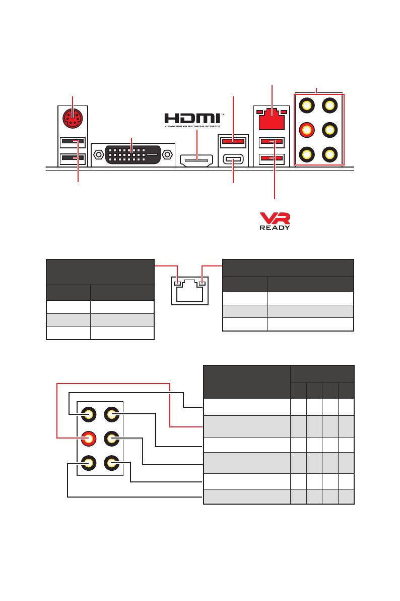
Задняя панель портов ввода/ вывода
Задняя панель портов ввода/ вывода
PS/2
LAN
DVI-D
Порты Аудио
USB 3.1 Gen1
USB 2.0
USB 3.1 Gen2
USB 3.1 Gen2 Type-C
Подключение/ Работа
индикатора
Состояние Описание
Выкл. Не подключен
Желтый Подключен
Мигает Передача данных
Скорость передачи данных
Состояние Описание
Выкл. 10 Мбит/с подключение
Зеленый 100 Мбит/с подключение
Оранжевый 1 Гбит/с подключение
Таблица состояний индикатора порта LAN
Конфигурация портов Аудио
Порты Аудио
Канал
2 4 6 8
Линейный вход
Линейный выход/ Выход
фронтальных колонок
● ● ● ●
Тыловые колонки ● ● ●
Выход центральной
колонки/ сабвуфера
● ●
Выход боковых колонок ●
Микрофонный вход
(●: подключен, Пусто: не подключен)
9
Задняя панель портов ввода/ вывода
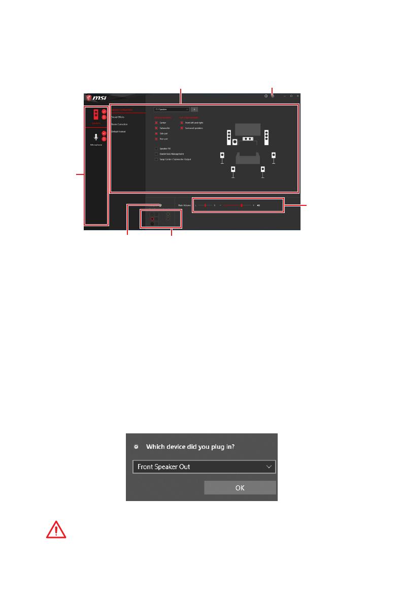
Realtek Audio Console
После установки Realtek Audio Console вы можете использовать его для
изменения параметров звука, чтобы улучшить качество звука.
y Выбор устройства — позволяет выбрать источник аудио выхода и изменить
соответствующие параметры. Отмеченное устройство будет использоваться
по умолчанию.
y Дополнительные эффекты — это список опций по настройке звуковых
эффектов для входного и выходного сигнала аудио устройства.
y Мастер—громкость — регулирует громкость или баланс правой и левой
колонок, подключенных к передней или задней панели.
y Расширенные настройки — обеспечивают работу с двумя независимыми
потоками аудио.
y Состояние разъемов — отображает все устройства воспроизведения и
записи, подключенные к компьютеру.
y Настройки подключений — настраивают параметры подключения.
Автоматическое всплывающее диалоговое окно
При подключении устройства к разъему аудио появится диалоговое окно с
просьбой подтвердить подключенное устройство.
Каждый разъем соответствует его настройкам по умолчанию, как показано
на следующей странице
Внимание
Изображения приведены исключительно в справочных целях и могут
отличаться от фактических.
Состояние разъемов
Настройки подключений
Выбор
устройства
Мастер—
громкость
Дополнительные эффекты Расширенные настройки
10
Задняя панель портов ввода/ вывода
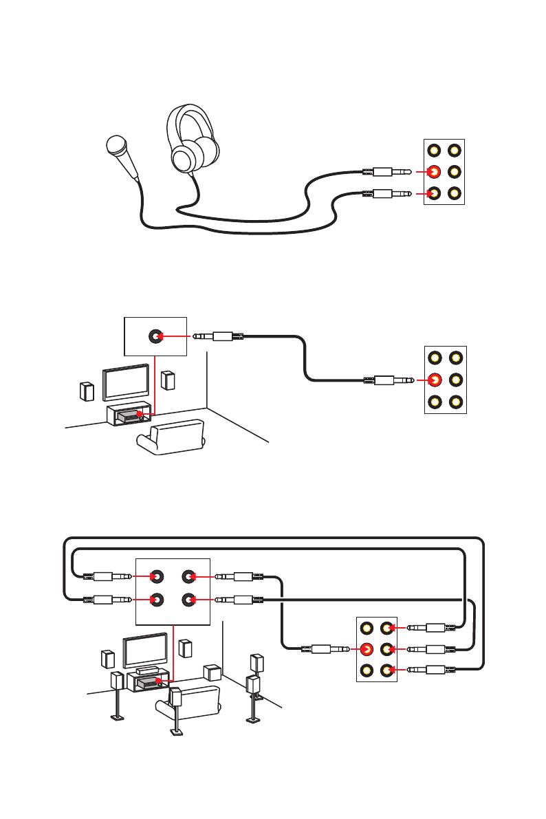
Подключение наушников и микрофона
Подключение внешнего стерео усилителя (колонок)
Подключение звуковой системы 7.1
AUDIO INPUT
Rear Front
Side Center/
Subwoofer
AUDIO INPUT
11
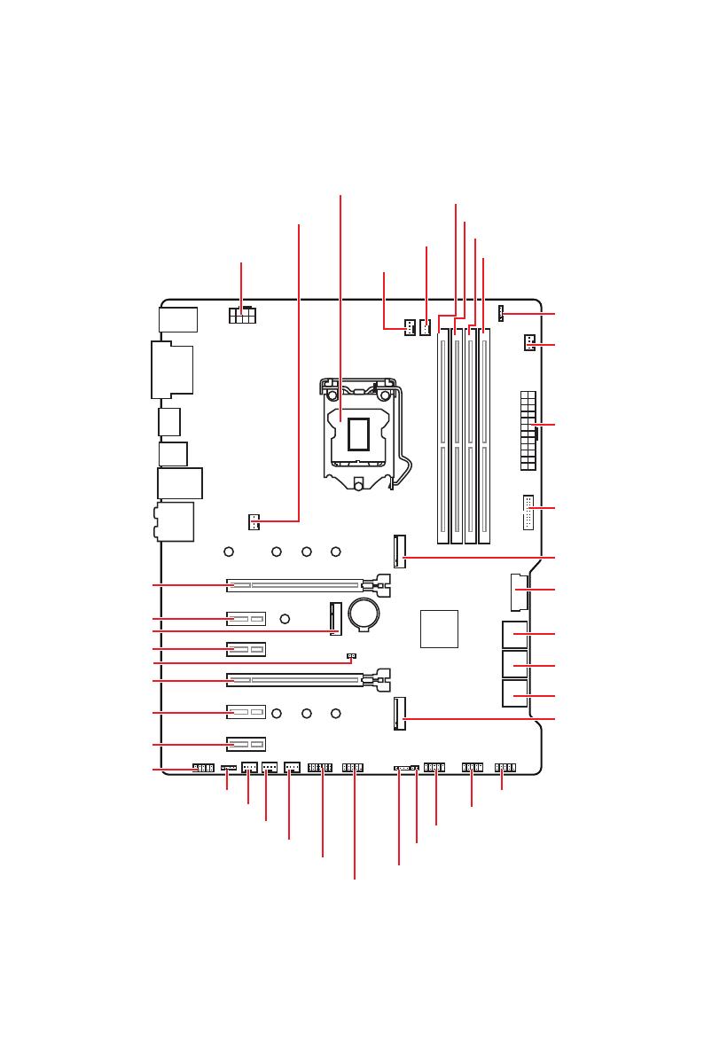
Компоненты материнской платы
BAT1
Компоненты материнской платы
DIMMA1
CPU_PWR1
Процессорный сокет
PCI_E1
PCI_E2
JBAT1
PCI_E3
CNVI_1
PCI_E4
PCI_E5
PCI_E6
JAUD1
DIMMA2
DIMMB1
DIMMB2
JRGB2
CPU_FAN1
PUMP_FAN1
SYS_FAN1
SYS_FAN5
SYS_FAN4
SYS_FAN2
SYS_FAN3
ATX_PWR1
JUSB4
JUSB3
M2_1
M2_2
JFP2
JCI1
SATA▼1▲2
SATA▼3▲4
SATA▼5▲6
JFP1
JCOM1
JUSB2
JTPM1
JUSB1
JRGB1
12
Компоненты материнской платы
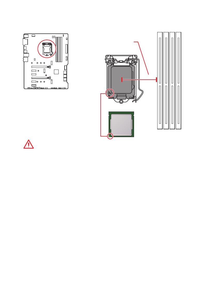
Процессорный сокет
Процессор LGA 1151
На поверхности процессора
LGA 1151 имеются две выемки
и золотой треугольник для
правильной установки процессора
относительно поцессорного сокета
материнской платы. Золотой
треугольник указывает на контакт 1.
Внимание!
y
Перед установкой или заменой процессора, необходимо отключить кабель
питания.
y
Пожалуйста, сохраните защитную крышку процессорного сокета после
установки процессора. Любые возможные гарантийные случаи, связанные с
работой материнской платы, MSI
®
будет рассматривать только, при наличии
защитной крышки на процессорном сокете.
y
При установке процессора обязательно установите процессорный
кулер. Кулер, представляющий собой систему охлаждения процессора,
предотвращает перегрев и обеспечивает стабильную работу системы.
y
Перед включением системы проверьте герметичность соединения между
процессором и радиатором.
y
Перегрев может привести к серьезному повреждению процессора и
материнской платы. Всегда проверяйте работоспособность вентилятора для
защиты процессора от перегрева. При установке кулера нанесите ровный
слой термопасты (или термоленту) на крышку установленного процессора
для улучшения теплопередачи.
y
Если процессор не установлен, всегда защищайте контакты процессорного
сокета пластиковой крышкой.
y
Если вы приобрели отдельно процессор и процессорный кулер, подробное
описание установки см. в документации в данному кулеру.
y
Данная системная плата разработана с учетом возможности ее
«разгона». Перед выполнением разгона системы убедитесь в том, что все
компоненты системы смогут его выдержать. Производитель не рекомендует
использовать параметры, выходящие за пределы технических характеристик
устройств. Гарантия MSI
®
не распространяется на повреждения и другие
возможные последствия ненадлежащей эксплуатации оборудования.
50.7 мм
Расстояние от центра
процессора до ближайшего
слота DIMM.
13
Компоненты материнской платы
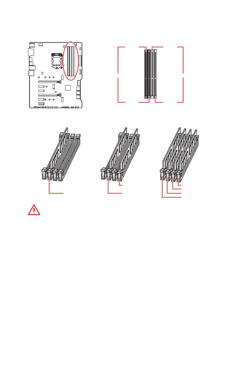
Слоты DIMM
DIMMA1 DIMMB1
Канал A Канал B
DIMMA2 DIMMB2
Рекомендации по установке модулей памяти
DIMMB2 DIMMB2
DIMMB1
DIMMA2 DIMMA2 DIMMA2
DIMMA1
Внимание!
y
Всегда устанавливайте модуль памяти сначала в слот DIMMA2.
y
В связи со спецификой использования ресурсов чипсета, доступный объем
памяти будет немного меньше, чем объем установленный.
y
На основе характеристик процессора, рекомендуется устанавливать
напряжение на памяти DIMM менее 1.35 В. Это позволит защитить
процессор.
y
Пожалуйста, обратите внимание на то, что максимальная емкость
адресуемой памяти для 32-бит ОС Windows, составляет не более 4 ГБ. Если вы
хотите использовать более 4ГБ оперативной памяти на материнской плате,
рекомендуется устанавливать 64-бит ОС Windows.
y
Некоторые модули памяти при разгоне могут работать на частотах ниже
заявленной производителем, поскольку выставляемая для памяти частота
зависит от информации, записанной в SPD (Serial Presence Detect). Зайдите
в BIOS и выберите опцию Memory Try It!, чтобы установить заявленную или
более высокую частоту.
y
При установке памяти во все слоты, а также при ее разгоне, рекомендуется
использовать более эффективную систему охлаждения памяти.
y
Совместимость и стабильность работы установленного модуля памяти при
разгоне зависит от установленного процессора и других устройств.
14
Компоненты материнской платы
BAT1
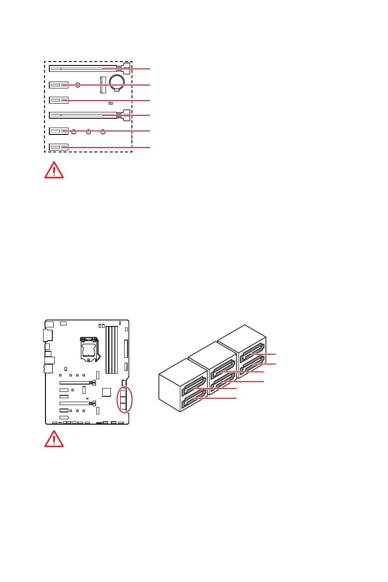
PCI_E1~6: Слоты расширения PCIe
PCI_E1: PCIe 3.0 x16 (линии CPU)
PCI_E2: PCIe 3.0 x1 (линии PCH)
PCI_E3: PCIe 3.0 x1 (линии PCH)
PCI_E5: PCIe 3.0 x1 (линии PCH)
PCI_E4: PCIe 3.0 x4 (линии PCH)
PCI_E6: PCIe 3.0 x1 (линии PCH)
Внимание!
y
При установке массивной видеокарты, необходимо использовать такой
инструмент, как MSI Gaming Series Graphics Card Bolster для поддержки веса
графической карты и во избежание деформации слота.
y
Для установки одной карты расширения PCIe x16 с оптимальной
производительностью рекомендуется использовать слот PCI_E1.
y
Перед установкой или извлечением плат расширения убедитесь, что
кабель питания отключен от электрической сети. Прочтите документацию
на карту расширения и выполните необходимые дополнительные
аппаратные или программные изменения для данной карты.
SATA1~6: Разъемы SATA 6Гб/с
Эти разъемы представляют собой интерфейсные порты SATA 6Гб/с. К
каждому порту можно подключить одно устройство SATA.
Внимание!
y
Избегайте перегибов кабеля SATA под прямым углом. В противном случае,
возможна потеря данных при передаче.
y
Кабели SATA оснащены одинаковыми коннекторами с обеих сторон.
Однако, для экономии занимаемого пространства к материнской плате
рекомендуется подключать плоский разъем.
y
Порт SATA2 будет недоступен при установке устройства M.2 SATA в разъем
M2_1.
y
Порты SATA5 & SATA6 будут недоступны при установке устройства M.2 PCIe/
SATA в разъем M2_2.
SATA1
SATA3
SATA2
SATA4
SATA5
SATA6
15
Компоненты материнской платы
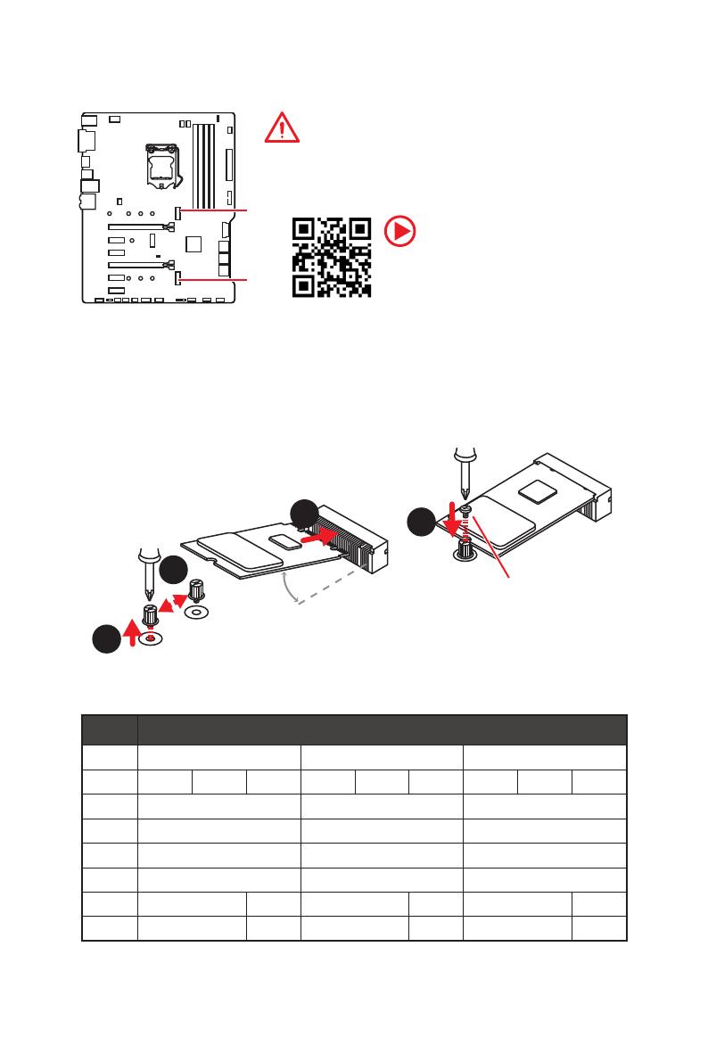
M2_1~2: Разъемы M.2 (Ключ M)
M2_1
M2_2
Внимание!
y
Intel
®
RST только поддерживает PCIe M.2 SSD с
UEFI ROM.
y
Поддержка памяти Intel
®
Optane™.
Установка устройства M.2
1
2
3
30°
1. M.2 модуля из материнской платы.
2. Закрутите стойку для крепления M.2
модуля в подходящее отверстие, в
соответствии с длиной вашего M.2
SSD.
3. Вставьте M.2 SSD в разъем М.2 под
углом 30 градусов.
4. Закрепите M.2 SSD с
помощью прилагаемого
винта для M.2.
4
Винт для M.2
Видео Инструкция
Смотрите видео, чтобы узнать как
установить модуль M.2.
http://youtu.be/JCTFABytrYA
Рекомендации по установке устройств M.2 и SATA
Слот Доступные разъемы SATA/ M.2
M2_1 PCIe SATA Пусто
M2_2 PCIe SATA Пусто PCIe SATA Пусто PCIe SATA Пусто
SATA1 ✓ ✓ ✓
SATA2 ✓ ─ ✓
SATA3 ✓ ✓ ✓
SATA4 ✓ ✓ ✓
SATA5 ─ ✓ ─ ✓ ─ ✓
SATA6 ─ ✓ ─ ✓ ─ ✓
(SATA: M.2 SATA SSD, PCIe: M.2 PCIe SSD, ✓: доступно, ─: недоступно)
16
Компоненты материнской платы
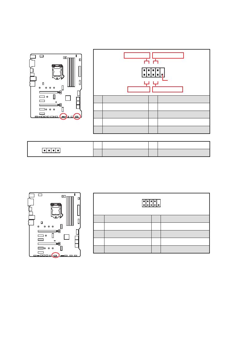
1
2 10
9
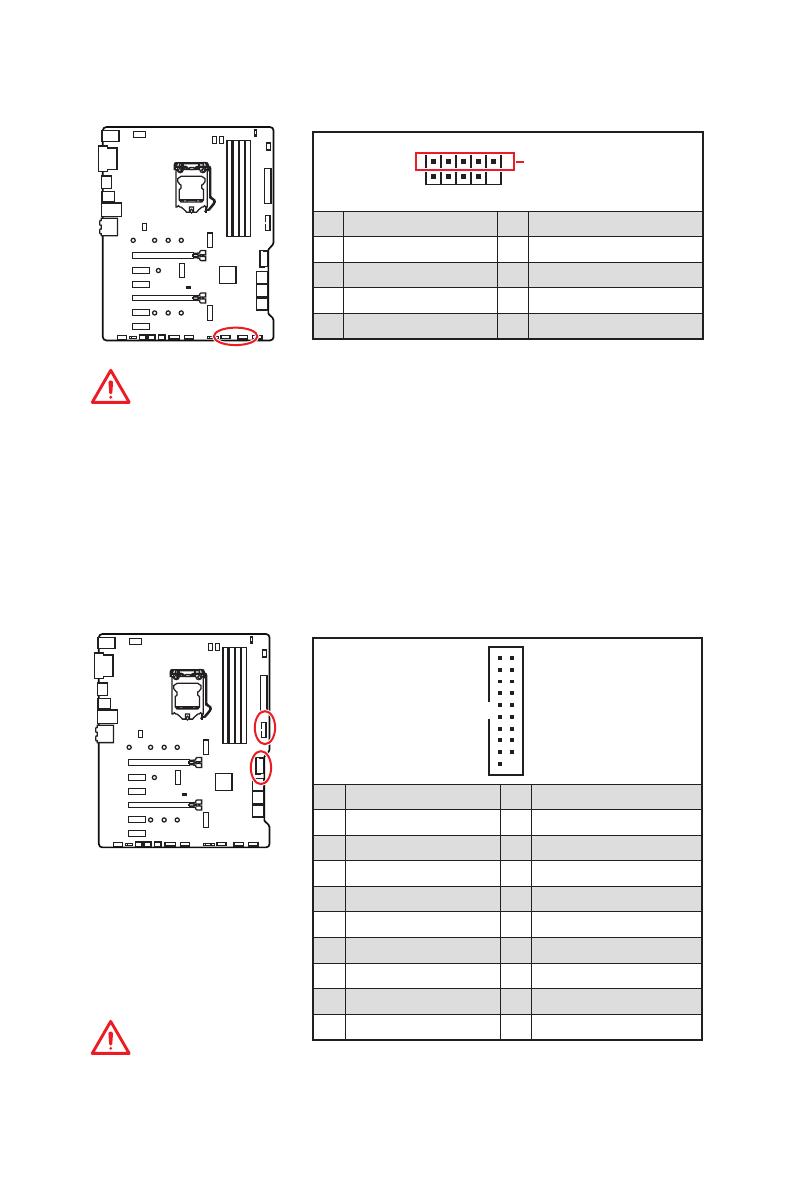
1 DCD 2 SIN
3 SOUT 4 DTR
5 Ground 6 DSR
7 RTS 8 CTS
9 RI 10 No Pin
JCOM1: Разъем последовательного порта
Данный разъем позволяет подключить последовательный порт,
размещенный на внешнем брекете.
JFP1, JFP2: Разъемы передней панели
Эти разъемы служат для подключения кнопок и светодиодных индикаторов,
расположенных на передней панели.
1
2 10
9
+
+
+—
——
—
+
Power LED
HDD LED Reset Switch
Reserved
Power Switch
JFP1
1 HDD LED + 2 Power LED +
3 HDD LED — 4 Power LED —
5 Reset Switch 6 Power Switch
7 Reset Switch 8 Power Switch
9 Reserved 10 No Pin
1
JFP2
1 Speaker — 2 Buzzer +
3 Buzzer — 4 Speaker +
17
Компоненты материнской платы
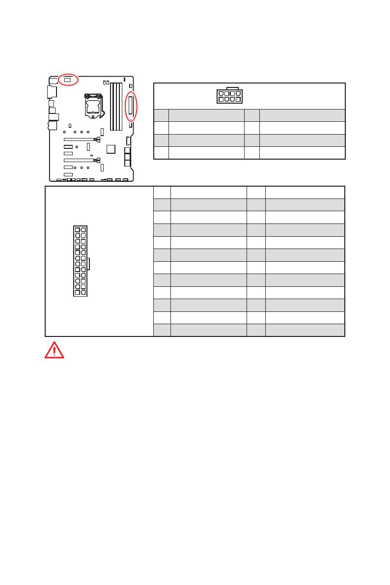
24
131
12
ATX_PWR1
1 +3.3V 13 +3.3V
2 +3.3V 14 -12V
3 Ground 15 Ground
4 +5V 16 PS-ON#
5 Ground 17 Ground
6 +5V 18 Ground
7 Ground 19 Ground
8 PWR OK 20 Res
9 5VSB 21 +5V
10 +12V 22 +5V
11 +12V 23 +5V
12 +3.3V 24 Ground
5
4 1
8
CPU_PWR1
1 Ground 5 +12V
2 Ground 6 +12V
3 Ground 7 +12V
4 Ground 8 +12V
Внимание!
Для обеспечения стабильной работы системной платы проверьте
надежность подключения всех кабелей питания к блоку питания АТХ.
CPU_PWR1, ATX_PWR1: Разъемы питания
Данные разъемы предназначены для подключения блока питания ATX.
18
Компоненты материнской платы
JUSB1~2: Разъемы USB 2.0
1
2 10
Примечание
9
1 VCC 2 VCC
3 USB0- 4 USB1-
5 USB0+ 6 USB1+
7 Ground 8 Ground
9 No Pin 10 NC
Примечание: Набор контактов JUSB2 будет недоступен при
установке модуля Intel wireless-AC (CNVi) в слот CNVI_1.
Внимание!
y
Помните, что во избежание повреждений, необходимо правильно
подключать контакты VCC и земли.
y
Для того, чтобы зарядить ваш iPad, iPhone и iPod через порты USB,
пожалуйста, установите утилиту MSI DRAGON CENTER.
y
Слоты CNVI_1 и JUSB2 используют одную полосу пропускания. Один порт
USB, подключенный к JUSB2, будет недоступен при установке устройства в
слот CNVI_1.
JUSB3~4: Разъемы USB 3.1 Gen1
Данные разъемы предназначены для подключения портов USB 3.1 Gen1 на
передней панели.
1
10 11
20
1 Power 11 USB2.0+
2 USB3_RX_DN 12 USB2.0-
3 USB3_RX_DP 13 Ground
4 Ground 14 USB3_TX_C_DP
5 USB3_TX_C_DN 15 USB3_TX_C_DN
6 USB3_TX_C_DP 16 Ground
7 Ground 17 USB3_RX_DP
8 USB2.0- 18 USB3_RX_DN
9 USB2.0+ 19 Power
10 GND 20 No Pin
Внимание!
Помните, что во избежание повреждений, необходимо правильно
подключать контакты питания и земли.
19
Компоненты материнской платы
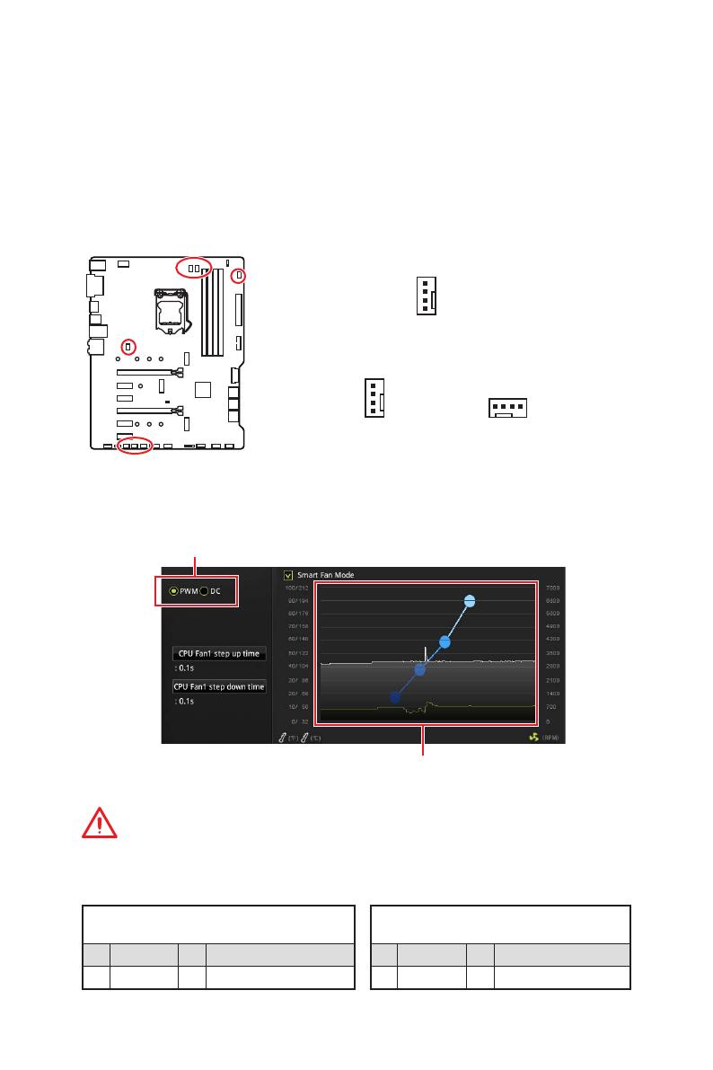
Переключение режимов работы и скорости вращения вентилятора
В меню BIOS > HARDWARE MONITOR вы можете выбрать режив работы
вентилятора: PWM или DC, а также настроить его скорость вращения.
Выберите режим PWM или DC
Внимание!
Убедитесь, что вентиляторы работают правильно после выбора режима
PWM/ DC.
Вы можете регулировать скорость вращения вентилятора
в зависимости от температуры процессора путем
изменения положения градиентных точек.
Назначение контактов разъема для режима
PWM
1 Ground 2 +12V
3 Sense 4 Speed Control Signal
Назначение контактов разъема для
режима DC
1 Ground 2 Voltage Control
3 Sense 4 NC
Назначение контактов разъема для подключения вентилятора
CPU_FAN1, PUMP_FAN1, SYS_FAN1~5: Разъемы вентиляторов
Разъемы вентиляторов можно разделить на два типа: с PWM (PulseWidth
Modulation) управлением и управлением постоянным током. Разъемы
вентиляторов с PWM управлением имеют контакт с постоянным напряжением
12В, а также контакт с сигналом управления скоростью вращения. Управление
скоростью вращения вентиляторов с управлением постоянным током,
осуществляется через соответсвующие разъемы путем изменения величины
напряжения.
Для настройки режима работы вентилятора вручную (PWM или
DC), следуйте указаниям ниже
.
CPU_FAN1/ PUMP_FAN1
Разъем вентилятора с управлением
PWM по умолчанию
Разъем вентилятора с управлением DC
по умолчанию
1
SYS_FAN1 & 5 SYS_FAN2, 3, 4
1
1
Встроенные индикаторы
Индикаторы отладки EZ
Данные светодиоды показывают состояния отладки материнской платы.
LED_SW1: Переключатель для управления индикаторами EZ
Этот переключатель используется для включения/ выключения всех индикаторов
на материнской плате.
CPU — процессор не обнаружен или поврежден.
DRAM — память DRAM не обнаружена или повреждена.
VGA — видеокарта не обнаружена или повреждена.
BOOT — устройство загрузки не обнаружено или
повреждено.
LED_OFF
LED_SW1
LED_ON
(По умолчанию)
Встроенные индикаторы
31
Quick Start
Thank you for purchasing the MSI® MPG Z490 GAMING PLUS motherboard. This Quick Start section provides demonstration diagrams about how to install your computer. Some of the installations also provide video demonstrations. Please link to the URL to watch it with the web browser on your phone or tablet. You may have even link to the URL by scanning the QR code.
MSI® MPG Z490 GAMING PLUS PCURLQR URL
MSI® MPG Z490 GAMING PLUS .
.URL . QRURL .
MSI® MPG Z490 GAMING PLUSURL QR code
MSI® MPG Z490 GAMING PLUS
QR URL
Quick Start I
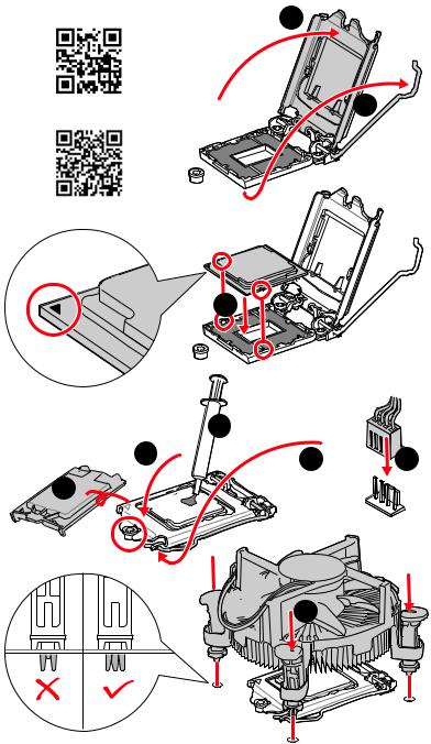
|
InstallingaProcessor/CPU / / |
|
|
/ |
2 |
|
Youtube |
|
|
1 |
|
https://v.youku.com/v_show/ id_XMTgxMzM2MjEzNg==.html
3
6

II Quick Start
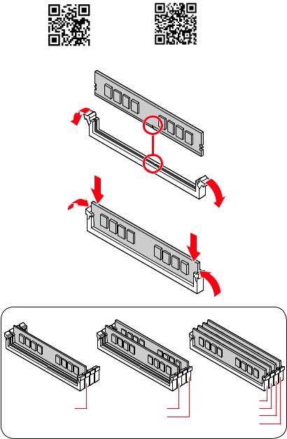
InstallingDDR4memory/DDR4 /
DDR4 / DDR4 / DDR4
http://youtu.be/T03aDrJPyQs http://v.youku.com/v_show/id_XNzUyMTI5ODI4.html
|
DIMMA2 |
DIMMA2 |
DIMMA1 |
|
DIMMA2 |
||
|
DIMMB2 |
DIMMB1 |
|
|
DIMMB2 |
Quick Start III

Connecting the Front Panel Header/
/ //
http://youtu.be/DPELIdVNZUI http://v.youku.com/v_show/id_XNjcyMTczMzM2.html
|
— |
|||
|
LED |
|||
|
LED+ |
POWER |
||
|
POWER |
|||
|
LED |
|||
|
SW |
HDD |
||
|
POWER |
|||
|
SW |
|||
|
RESET |
|
Power LED |
Power Switch |
||||||||||||||||||||
|
-+-+ |
|||||||||||||||||||||
|
JFP1 |
2 |
10 |
|||||||||||||||||||
|
1 |
9 |
Reserved |
|||||||||||||||||||
|
+ +— |
|||||||||||||||||||||
|
HDD LED |
Reset Switch |
||||||||||||||||||||
|
1 |
HDD LED + |
2 |
Power LED + |
||||||||||||||||||
|
3 |
HDD LED — |
4 |
Power LED — |
||||||||||||||||||
|
5 |
Reset Switch |
6 |
Power Switch |
||||||||||||||||||
|
7 |
Reset Switch |
8 |
Power Switch |
||||||||||||||||||
|
9 |
Reserved |
10 |
No Pin |
HDDLED RESETSW
|
HDD LED — |
|||||||
|
HDD LED |
|||||||
|
HDD LED + |
|||||||
|
POWER LED — |
|||||||
|
POWER LED |
POWER LED + |
||||||
IV Quick Start
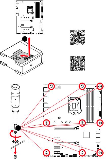
InstallingtheMotherboard/ /
/ /
https://v.youku.com/v_show/id_
XNDUwMDUyNTkwOA==.html
*3 kgf·cm = 0.3 N·m = 2.6 lbf·in
Quick Start V

ConnectingthePowerConnectors/ // /
http://youtu.be/gkDYyR_83I4 http://v.youku.com/v_show/id_XNDkzODU0MDQw.html
ATX_PWR1
CPU_PWR2

VI Quick Start
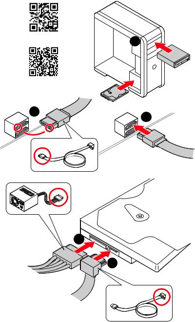
InstallingSATADrives/SATA /
SATA / SATA / SATA
Youtube
|
1 |
|
|
http://v.youku |
|
|
id_XNDkzODU5MTky.html |
|
|
2 |
3 |
5
4
Quick Start VII

InstallingaGraphicsCard/ /
/ /
Youtube
1
http://v.youku id_XNDkyOTc3MzQ4.html
5

6
VIII Quick Start

ConnectingPeripheralDevices/ /
/ /
Quick Start IX
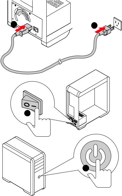
X Quick Start
|
Contents |
|
|
Safety Information……………………………………………………………………………………. |
3 |
|
Specifications…………………………………………………………………………………………… |
4 |
|
Package contents……………………………………………………………………………………… |
9 |
|
Rear I/O Panel………………………………………………………………………………………… |
10 |
|
LAN Port LED Status Table……………………………………………………………………….. |
10 |
|
Audio Ports Configuration…………………………………………………………………………. |
10 |
|
Realtek Audio Console……………………………………………………………………………… |
11 |
|
Overview of Components…………………………………………………………………………. |
13 |
|
CPU Socket……………………………………………………………………………………………… |
14 |
|
DIMM Slots……………………………………………………………………………………………… |
15 |
|
PCI_E1~5: PCIe Expansion Slots……………………………………………………………….. |
16 |
|
M2_1~2: M.2 Slots (Key M)………………………………………………………………………… |
17 |
|
SATA1~6: SATA 6Gb/s Connectors…………………………………………………………….. |
19 |
|
JFP1, JFP2: Front Panel Connectors…………………………………………………………. |
20 |
|
JCOM1: Serial Port Connector…………………………………………………………………… |
20 |
|
CPU_PWR1~2, ATX_PWR1: Power Connectors……………………………………………. |
21 |
|
JAUD1: Front Audio Connector………………………………………………………………….. |
22 |
|
JUSB5: USB 3.2 Gen 1 Type-C Connector…………………………………………………… |
22 |
|
JUSB3~4: USB 3.2 Gen 1 Connectors…………………………………………………………. |
23 |
|
JUSB1~2: USB 2.0 Connectors………………………………………………………………….. |
24 |
|
JTPM1: TPM Module Connector………………………………………………………………… |
24 |
|
CPU_FAN1, PUMP_FAN1, SYS_FAN1~6: Fan Connectors……………………………. |
25 |
|
JCI1: Chassis Intrusion Connector…………………………………………………………….. |
26 |
|
JTBT1: Thunderbolt Add-on Card Connector………………………………………………. |
27 |
|
JRTD3: Intel RTD3 Connector……………………………………………………………………. |
27 |
|
JBAT1: Clear CMOS (Reset BIOS) Jumper………………………………………………….. |
28 |
|
JRGB1: RGB LED connector……………………………………………………………………… |
29 |
|
JRAINBOW1~2: Addressable RGB LED connectors……………………………………… |
30 |
|
Onboard LEDs…………………………………………………………………………………………. |
31 |
|
EZ Debug LED…………………………………………………………………………………………. |
31 |
|
LED_SW1: EZ LED Control………………………………………………………………………… |
31 |
|
Installing OS, Drivers & Utilities……………………………………………………………….. |
32 |
|
Installing Windows® 10……………………………………………………………………………… |
32 |
|
Installing Drivers……………………………………………………………………………………… |
32 |
|
Installing Utilities…………………………………………………………………………………….. |
32 |
|
UEFI BIOS………………………………………………………………………………………………. |
33 |
|
BIOS Setup……………………………………………………………………………………………… |
34 |
Contents 1
|
Entering BIOS Setup………………………………………………………………………………… |
34 |
|
Resetting BIOS………………………………………………………………………………………… |
35 |
|
Updating BIOS…………………………………………………………………………………………. |
35 |
|
EZ Mode………………………………………………………………………………………………….. |
37 |
|
Advanced Mode ………………………………………………………………………………………. |
40 |
|
OC Menu…………………………………………………………………………………………………. |
41 |
2 Contents
Safety Information
∙∙The components included in this package are prone to damage from electrostatic discharge (ESD). Please adhere to the following instructions to ensure successful computer assembly.
∙∙Ensure that all components are securely connected. Loose connections may cause the computer to not recognize a component or fail to start.
∙∙Hold the motherboard by the edges to avoid touching sensitive components.
∙∙It is recommended to wear an electrostatic discharge (ESD) wrist strap when handling the motherboard to prevent electrostatic damage. If an ESD wrist strap is not available, discharge yourself of static electricity by touching another metal object before handling the motherboard.
∙∙Store the motherboard in an electrostatic shielding container or on an anti-static pad whenever the motherboard is not installed.
∙∙Before turning on the computer, ensure that there are no loose screws or metal components on the motherboard or anywhere within the computer case.
∙∙Do not boot the computer before installation is completed. This could cause permanent damage to the components as well as injury to the user.
∙∙If you need help during any installation step, please consult a certified computer technician.
∙∙Always turn off the power supply and unplug the power cord from the power outlet before installing or removing any computer component.
∙∙Keep this user guide for future reference. ∙∙Keep this motherboard away from humidity.
∙∙Make sure that your electrical outlet provides the same voltage as is indicated on the PSU, before connecting the PSU to the electrical outlet.
∙∙Place the power cord such a way that people can not step on it. Do not place anything over the power cord.
∙∙All cautions and warnings on the motherboard should be noted.
∙∙If any of the following situations arises, get the motherboard checked by service personnel:
▪▪Liquid has penetrated into the computer.
▪▪The motherboard has been exposed to moisture.
▪▪The motherboard does not work well or you can not get it work according to user guide.
▪▪The motherboard has been dropped and damaged. ▪▪The motherboard has obvious sign of breakage.
∙∙Do not leave this motherboard in an environment above 60°C (140°F), it may damage the motherboard.
Safety Information 3

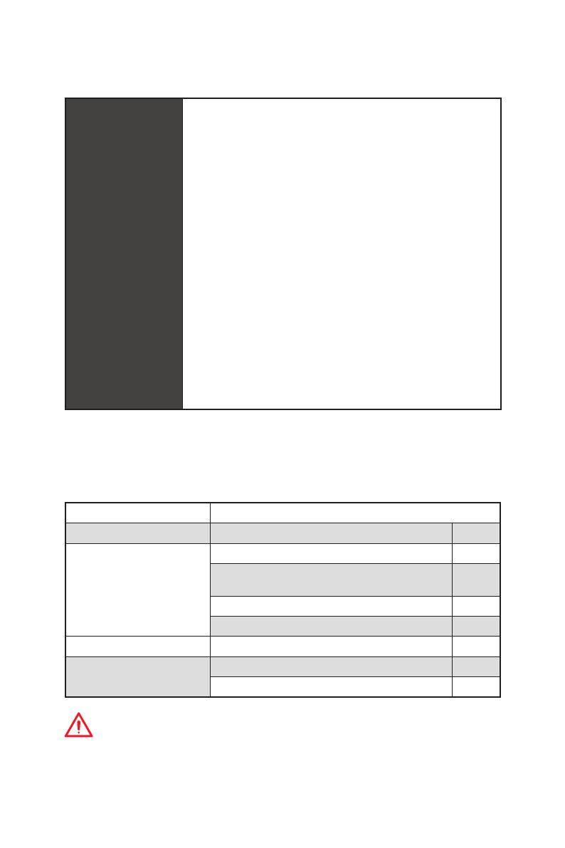
Specifications
|
Supports 10th Gen Intel® Core™ and Pentium® Gold / |
|
|
CPU |
Celeron® processors for LGA 1200 socket* |
|
* Please go to intel.com for compatibility information. |
|
|
* Onboard graphics output are disabled when using the F SKU processors. |
|
|
Chipset |
Intel® Z490 Chipset |
|
∙∙4x DDR4 memory slots, support up to 128GB* |
|
|
∙∙Supports 1R 2133/2666/2933 MHz* |
|
|
▪▪1DPC 1R Max speed up to 4800+ MHz |
|
|
▪▪1DPC 2R Max speed up to 4266+ MHz |
|
|
Memory |
▪▪2DPC 1R Max speed up to 4400+ MHz |
|
▪▪2DPC 2R Max speed up to 4000+ MHz |
|
|
∙∙Supports Dual-Channel mode |
|
|
∙∙Supports non-ECC, un-buffered memory |
|
|
∙∙Supports Intel® Extreme Memory Profile (XMP) |
|
|
*Please refer www.msi.com for more information on compatible memory |
|
|
Expansion Slot |
∙∙1x PCIe 3.0 x16 slot (from CPU) |
|
∙∙1x PCIe 3.0 x16 slot (from PCH supports x4 mode) |
|
|
∙∙3x PCIe x1 slots (from PCH) |
|
|
∙∙1x HDMI port, supports a maximum resolution of |
|
|
Onboard Graphics |
4096×2160 @ 30Hz |
|
∙∙1x DisplayPort port supports a maximum resolution of |
|
|
4096 x 2304 @ 60Hz |
|
|
Multi-GPU |
Supports 2-Way AMD® CrossFire™ Technology |
|
Intel® Z490 Chipset |
|
|
∙∙6x SATA 6Gb/s ports* |
|
|
∙∙2x M.2 slots (Key M) |
|
|
▪▪M2_1 supports up to PCIe 3.0 x4 and SATA 6Gb/s, 2242/ |
|
|
2260/ 2280/ 22110 storage devices* |
|
|
Storage |
▪▪M2_2 supports up to PCIe 3.0 x4 and SATA 6Gb/s, 2242/ |
|
2260/ 2280 storage devices** |
|
|
▪▪Intel® Optane™ Memory Ready*** |
|
|
▪▪Supports Intel® Smart Response Technology for Intel |
|
|
Core™ processors |
|
|
* SATA2 will be unavailable when installing M.2 SATA SSD in the M2_1 slot. |
|
|
** SATA5 & SATA6 will be unavailable when installing M.2 SATA/PCIe SSD in the |
|
|
M2_2 slot. |
|
|
*** Before using Intel® Optane™ memory modules, please ensure that you have |
|
|
updated the drivers and BIOS to the latest version from MSI website. |
|
|
Continued on next page |
4 Specifications

|
Continued from previous page |
|
|
Intel® Z490 Chipset |
|
|
RAID |
∙∙Supports RAID 0, RAID 1, RAID 5 and RAID 10 for SATA |
|
storage devices |
|
|
∙∙Supports RAID 0 and RAID 1 for M.2 PCIe storage devices |
|
|
LAN |
1x Realtek® RTL8125B-CG 2.5G LAN Controller |
|
∙∙Intel® Z490 Chipset |
|
|
▪▪2x USB 3.2 Gen 2 10Gbps ports (1 Type-A port and 1 |
|
|
Type-C port on the back panel) |
|
|
USB |
▪▪7x USB 3.2 Gen 1 5Gbps ports (2 Type-A ports on the |
|
back panel, 4 ports through the internal USB connectors, |
|
|
1 Type-C internal connector) |
|
|
▪▪6x USB 2.0 ports (2 Type-A ports on the back panel, 4 |
|
|
ports through the internal USB 2.0 connectors) |
|
|
Audio |
Realtek® ALC1200-VD1 Codec |
|
∙∙7.1-Channel High Definition Audio |
|
|
∙∙Supports S/PDIF output |
|
|
∙∙1x PS/2 keyboard/ mouse combo port |
|
|
∙∙2x USB 2.0 ports |
|
|
∙∙1x HDMI port |
|
|
Back Panel |
∙∙1x DisplayPort port |
|
∙∙1x USB 3.2 Gen 2 10Gbps Type-A port |
|
|
Connectors |
∙∙1x USB 3.2 Gen 2 10Gbps Type-C port |
|
∙∙1x LAN(RJ45) port |
|
|
∙∙2x USB 3.2 Gen 1 5Gbps Type-A ports |
|
|
∙∙1x Optical S/PDIF OUT connector |
|
|
∙∙5x audio jacks |
|
|
Continued on next page |
Specifications 5

Continued from previous page
∙∙1x 24-pin ATX main power connector ∙∙1x 8-pin ATX 12V power connector ∙∙1x 4-pin ATX 12V power connector ∙∙6x SATA 6Gb/s connectors
∙∙1x USB 3.2 Gen 1 5Gbps Type-C port
∙∙2x USB 3.2 Gen 1 5Gbps connectors (support additional 4 USB 3.2 Gen 1 5Gbps ports)
∙∙2x USB 2.0 connectors (support additional 4 USB 2.0 ports) ∙∙1x 4-pin CPU fan connector
∙∙1x 4-pin water pump connector Internal Connectors ∙∙6x 4-pin system fan connectors
∙∙1x front panel audio connector ∙∙2x system panel connectors
∙∙1x Chassis Intrusion connector ∙∙1x Clear CMOS jumper
∙∙1x 4-pin RGB LED connector
∙∙2x 3-pin RAINBOW LED connectors
∙∙1x serial port connector ∙∙1x TPM module connector
∙∙1x TBT connector*
|
*Thunderbolt card need support RTD3 |
|
|
LED Features |
∙∙1x EZ LED Control switch |
|
∙∙4x EZ Debug LED |
|
|
I/O Controller |
NUVOTON NCT6687 Controller Chip |
|
Hardware Monitor |
∙∙CPU/System temperature detection |
|
∙∙CPU/System fan speed detection |
|
|
∙∙CPU/System fan speed control |
|
|
Form Factor |
∙∙ATX Form Factor |
|
∙∙12 in. x 9.6 in. (30.5 cm x 24.4 cm) |
|
|
∙∙1x 256 Mb flash |
|
|
BIOS Features |
∙∙UEFI AMI BIOS |
|
∙∙ACPI 6.2, SM BIOS 3.2 |
|
|
∙∙Multi-language |
|
|
Continued on next page |
6 Specifications

|
Continued from previous page |
||
|
∙∙Drivers |
||
|
∙∙DRAGON CENTER |
||
|
∙∙Intel Extreme Tuning Utility |
||
|
Software |
∙∙MSI App Player (BlueStacks) |
|
|
∙∙Open Broadcaster Software (OBS) |
||
|
∙∙CPU-Z MSI GAMING |
||
|
∙∙Google Chrome™, Google Toolbar, Google Drive |
||
|
∙∙Norton™ Internet Security Solution |
||
|
∙∙Gaming Mode |
||
|
∙∙Gaming Hotkey |
||
|
∙∙LAN Manager |
||
|
∙∙Mystic Light |
||
|
∙∙User Scenario |
||
|
Dragon Center |
∙∙Monitor(Hardware |
|
|
Monitor) |
||
|
Features |
∙∙True Color |
Please refer to http://download.msi. |
|
∙∙Live Update |
com/manual/mb/DRAGONCENTER2. |
|
|
∙∙DPC Latency tuner |
pdf for more details. |
|
|
∙∙Speed Up |
||
|
∙∙Smart Tool |
||
|
∙∙Super Charger |
||
|
∙∙Audio |
||
|
▪▪Audio Boost |
||
|
∙∙Network |
||
|
▪▪2.5G LAN |
||
|
Special Features |
▪▪LAN Manager |
|
|
∙∙Cooling |
||
|
▪▪Extended Heatsink Design |
||
|
▪▪M.2 Shield Frozr |
||
|
▪▪Pump Fan |
||
|
▪▪Smart Fan Control |
||
|
Continued on next page |
Specifications 7

Continued from previous page
∙∙LED
▪▪Mystic Light
▪▪Mystic Light Extension(RGB)
▪▪Mystic Light Extension (RAINBOW)
▪▪Mystic Light Sync
▪▪EZ LED Control ▪▪EZ DEBUG LED
∙∙Performance
▪▪Multi GPU-CrossFire Technology ▪▪DDR4 Boost
▪▪Core Boost
Special Features ▪▪Game Boost
▪▪USB 3.2 Gen 2 10G ▪▪USB with type A+C ▪▪Front USB type-C ▪▪Dual CPU Power
∙∙Protection
▪▪PCI-E Steel Armor ▪▪PCI-E Steel Slot ▪▪Pre-installed I/O Shielding
∙∙Experience
▪▪DRAGON CENTER
▪▪Click BIOS 5
8 Specifications

Package contents
Please check the contents of your motherboard package. It should contain:
|
Motherboard |
MPG Z490 GAMING PLUS |
|||
|
Documentation |
User manual |
1 |
||
|
Case stand-off notification |
1 |
|||
|
Quick installation guide |
1 |
|||
|
Application |
Driver DVD |
1 |
||
|
Cables |
SATA 6G cables (2 cables/pack) |
1 |
||
|
Accessories |
Case badge |
1 |
||
|
Product registration card |
1 |
|||
|
M.2 screws (3 pcs./pack) |
1 |
|||
|
If |
Important
any of the above items are damaged or missing, please contact your retailer.
Package contents 9
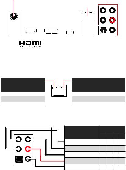
Rear I/O Panel
|
PS/2 Combo port |
Audio Ports |
|
2.5Gbps LAN |
|
|
USB 3.2 Gen 2 |
|
|
10Gbps Type A |
|
Optical |
||||||||||||||||||||||||||||||||||||
|
USB 3.2 |
Gen 2 |
|||||||||||||||||||||||||||||||||||
|
10Gbps Type C |
S/PDIF-Out |
|||||||||||||||||||||||||||||||||||
|
USB 3.2 Gen 1 |
||||||||||||||||||||||||||||||||||||
|
USB 2.0 Type-A |
DisplayPort |
|||||||||||||||||||||||||||||||||||
|
5Gbps Type A |
LAN Port LED Status Table
Link/ Activity LED
|
Status |
Description |
|
Off |
No link |
|
Yellow |
Linked |
|
Blinking |
Data activity |
Speed LED
|
Status |
Description |
|
Off |
10 Mbps connection |
|
Green |
100 Mbps / 1 Gbps connection |
|
Orange |
2.5 Gbps connection |
Audio Ports Configuration
|
Audio Ports |
Channel |
||||
|
2 |
4 |
6 |
8 |
||
|
Center/ Sub-woofer Out |
● |
● |
|||
|
Rear Speaker Out |
● |
● |
● |
||
|
Line-In/ Side Speaker Out |
● |
||||
|
Line-Out/ Front Speaker Out |
● |
● |
● |
● |
|
|
Mic In |
|||||
|
(●: connected, Blank: empty) |
10 Rear I/O Panel

Realtek Audio Console |
|
|
After Realtek Audio Console is installed. You can use it to change sound settings to get |
|
|
better sound experience. |
Application Enhancement |
Device
Selection

|
Connector Settings |
Jack |
Status |
|
∙∙Device Selection — allows you to select a audio output source to change the related options. The check sign indicates the devices as default.
∙∙Application Enhancement — the array of options will provide you a complete guidance of anticipated sound effect for both output and input device.
∙∙Main Volume — controls the volume or balance the right/left side of the speakers that you plugged in front or rear panel by adjust the bar.
∙∙Jack Status — depicts all render and capture devices currently connected with your computer.
∙∙Connector Settings — configures the connection settings.
Auto popup dialog
When you plug into a device at an audio jack, a dialogue window will pop up asking you which device is current connected.
Each jack corresponds to its default setting as shown on the next page.
Important
The pictures above for reference only and may vary from the product you purchased.
Rear I/O Panel 11

Audio jacks to headphone and microphone diagram
Audio jacks to stereo speakers diagram
AUDIO INPUT
Audio jacks to 7.1-channel speakers diagram
AUDIO INPUT
|
Rear |
Front |
|
Side |
Center/ |
|
Subwoofer |
12 Rear I/O Panel
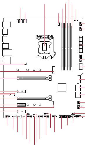
Overview of Components
|
CPU Socket |
DIMMB1 |
|||
|
CPU_PWR1 |
DIMMA2 DIMMB2 |
|||
|
DIMMA1 |
JRAINBOW1 |
|||
|
CPU_PWR2 |
CPU_FAN1 |
|||
|
PUMP_FAN1 |
||||
|
SYS_FAN6 |
||||
|
ATX_PWR1 |
||||
|
SYS_FAN1 |
JUSB4 |
|||
|
JUSB5 |
||||
|
M2_1 |
||||
|
PCI_E1 |
JUSB3 |
|||
|
PCI_E2 |
SATA▼1▲2 |
|||
|
JCI1 |
SATA▼3▲4 |
|||
|
JBAT |
||||
|
PCI_E3 |
SYS_FAN5 |
|||
|
PCI_E4 |
||||
|
M2_2 |
SYS_FAN4 |
|||
|
PCI_E5 |
JRTD3 |
|||
|
JFP1 |
||||
|
JAUD1 |
JT1 |
SATA6JTBT1 |
||
|
JRGB1 |
||||
|
SYS_FAN2 |
JUSB1 |
JTPM1SATA5 |
||
|
SYS_FAN3 |
||||
|
LED_SW1 |
JUSB2 |
|||
|
JCOM1 |
JFP2 |
|||
|
JRAINBOW2 |
Overview of Components 13
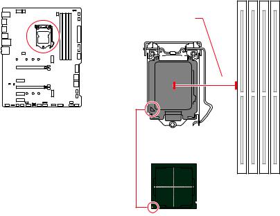
CPU Socket
Distance from the center of the
CPU to the nearest DIMM slot.
50.77 mm
Introduction to the LGA 1200 CPU
The surface of the LGA 1200 CPU has two notches and a golden triangle to assist in correctly lining up the CPU for motherboard placement. The golden triangle is the Pin 1 indicator.
Important
∙∙Always unplug the power cord from the power outlet before installing or removing the CPU.
∙∙Please retain the CPU protective cap after installing the processor.MSI will deal with Return Merchandise Authorization (RMA) requests if only the motherboard comes with the protective cap on the CPU socket.
∙∙When installing a CPU, always remember to install a CPU heatsink.A CPU heatsink is necessary to prevent overheating and maintain system stability.
∙∙Confirm that the CPU heatsink has formed a tight seal with the CPU before booting your system.
∙∙Overheating can seriously damage the CPU and motherboard.Always make sure the cooling fans work properly to protect the CPU from overheating.Be sure to apply an even layer of thermal paste (or thermal tape) between the CPU and the heatsink to enhance heat dissipation.
∙∙Whenever the CPU is not installed, always protect the CPU socket pins by covering the socket with the plastic cap.
∙∙If you purchased a separate CPU and heatsink/ cooler, Please refer to the documentation in the heatsink/ cooler package for more details about installation.
∙∙This motherboard is designed to support overclocking.Before attempting to overclock, please make sure that all other system components can tolerate overclocking.Any attempt to operate beyond product specifications is not recommended. MSI® does not guarantee the damages or risks caused by inadequate operation beyond product specifications.
14 Overview of Components
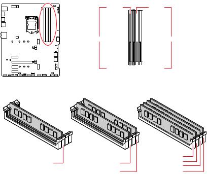
DIMM Slots
DIMMA1 DIMMB1
|
Channel A |
Channel B |
|||||||||||||||||||||||
DIMMA2
Memory module installation recommendation
|
DIMMA1 |
|||
|
DIMMA2 |
DIMMA2 |
DIMMA2 |
|
|
DIMMB1 |
|||
|
∙∙ |
DIMMB2 |
DIMMB2 |
|
Important
Always insert memory modules in the DIMMA2 slot first.
∙∙To ensure system stability for Dual channel mode, memory modules must be of the same type, number and density.
∙∙Some memory modules may operate at a lower frequency than the marked value when overclocking due to the memory frequency operates dependent on its Serial
Presence Detect (SPD).Go to BIOS and find the DRAM Frequency to set the memory frequency if you want to operate the memory at the marked or at a higher frequency.
∙∙It is recommended to use a more efficient memory cooling system for full DIMMs installation or overclocking.
∙∙The stability and compatibility of installed memory module depend on installed CPU and devices when overclocking.
∙∙Please refer www.msi.com for more information on compatible memory.
Overview of Components 15

PCI_E1~5: PCIe Expansion Slots

PCI_E2: PCIe 3.0 x1 (PCH)

PCI_E4: PCIe 3.0 x1 (PCH)
PCI_E5: PCIe 3.0 x1 (PCH)
Important
∙∙If you install a large and heavy graphics card, you need to use a tool such as MSI Gaming Series Graphics Card Bolster to support its weight to prevent deformation of the slot.
∙∙For a single PCIe x16 expansion card installation with optimum performance, using the PCI_E1 slot is recommended.
∙∙When adding or removing expansion cards, always turn off the power supply and unplug the power supply power cable from the power outlet. Read the expansion card’s documentation to check for any necessary additional hardware or software changes.
16 Overview of Components
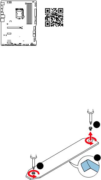
M2_1~2: M.2 Slots (Key M)
Video Demonstration
Watch the video to learn how to Install
M.2 module. http://youtu.be/JCTFABytrYA
Important
∙∙Intel® RST only supports PCIe M.2 SSD with UEFI ROM. ∙∙Intel® Optane™ Memory Ready for all M.2 slots.
Installing M.2 module
1. Loosen the screws of M.2 SHIELD FROZR heatsink. (For installing M.2 module to M2_2 slot, please skip to step 3)
2. Remove the M.2 SHIELD FROZR and remove the protective films from the thermal pads.
1
2
1
Overview of Components 17
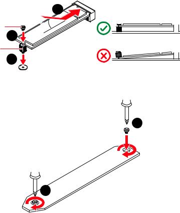
3.Move the position of the standoffs according to your M.2 SSDs length if need.
4.Insert your M.2 SSD into the M.2 slot at a 30-degree angle.
5.Secure the M.2 SSD in place with the supplied M.2 8.5H screw.
4
|
8.5H screw |
30º |
|
5 |
|
|
Standoff |
3 |
6. Put the M.2 SHIELD FROZR heatsink back in place and secure it.
6
6
18 Overview of Components

SATA1~6: SATA 6Gb/s Connectors
These connectors are SATA 6Gb/s interface ports. Each connector can connect to one SATA device.
SATA2
SATA1
SATA4
SATA3
SATA5
SATA6
Important
∙∙Please do not fold the SATA cable at a 90-degree angle.Data loss may result during transmission otherwise.
∙∙SATA cables have identical plugs on either sides of the cable.However, it is recommended that the flat connector be connected to the motherboard for space saving purposes.
∙∙SATA2 will be unavailable when installing M.2 SATA SSD in the M2_1 slot.
∙∙SATA5 & SATA6 will be unavailable when installing M.2 SSD in the M2_2 slot.
M.2 & SATA combination table
|
Slot |
PCIe |
SATA |
Available SATA connectors |
PCIe |
SATA |
|
|
M2_1 |
PCIe |
SATA |
||||
|
M2_2 |
PCIe |
PCIe |
SATA |
SATA |
─ |
─ |
|
SATA1 |
||||||
|
SATA2 |
─ |
─ |
─ |
|||
|
SATA3 |
||||||
|
SATA4 |
||||||
|
SATA5 |
─ |
─ |
─ |
─ |
||
|
SATA6 |
─ |
─ |
─ |
─ |
(SATA: M.2 SATA SSD, PCIe: M.2 PCIe SSD, : available, ─: unavailable)
Overview of Components 19
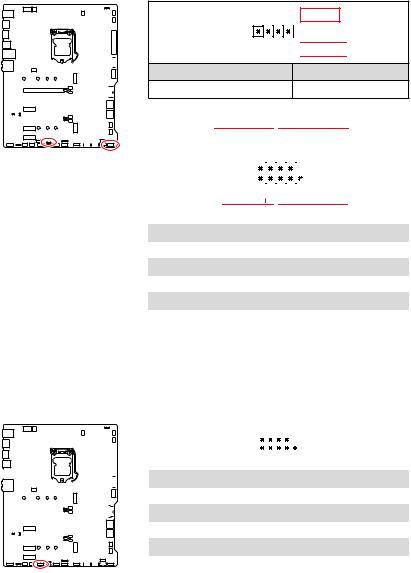
JFP1, JFP2: Front Panel Connectors
These connectors connect to the switches and LEDs on the front panel.
|
-+ |
||||||||||||||||||||||||||||
|
JFP2 |
—1 |
+ |
||||||||||||||||||||||||||
|
1 |
Speaker — |
2 |
||||||||||||||||||||||||||
|
3 |
Buzzer — |
4 |
||||||||||||||||||||||||||
Buzzer

Buzzer +
Speaker +
|
Power LED |
Power Switch |
||||||||||||||||||||||||||
|
-+-+ |
|||||||||||||||||||||||||||
|
JFP1 |
2 |
10 |
|||||||||||||||||||||||||
|
1 |
9 |
Reserved |
|||||||||||||||||||||||||
|
+ +— |
|||||||||||||||||||||||||||
|
HDD LED |
Reset Switch |
||||||||||||||||||||||||||
|
1 |
HDD LED + |
2 |
Power LED + |
||||||||||||||||||||||||
|
3 |
HDD LED — |
4 |
Power LED — |
||||||||||||||||||||||||
|
5 |
Reset Switch |
6 |
Power Switch |
||||||||||||||||||||||||
|
7 |
Reset Switch |
8 |
Power Switch |
||||||||||||||||||||||||
|
9 |
Reserved |
10 |
No Pin |
JCOM1: Serial Port Connector
This connector allows you to connect the optional serial port with bracket.
|
2 |
10 |
||||||||||||||||||||||||||||||||||
|
1 |
9 |
||||||||||||||||||||||||||||||||||
|
1 |
DCD |
2 |
SIN |
||||||||||||||||||||||||||||||||
|
3 |
SOUT |
4 |
DTR |
||||||||||||||||||||||||||||||||
|
5 |
Ground |
6 |
DSR |
||||||||||||||||||||||||||||||||
|
7 |
RTS |
8 |
CTS |
||||||||||||||||||||||||||||||||
|
9 |
RI |
10 |
No Pin |
||||||||||||||||||||||||||||||||
20 Overview of Components

CPU_PWR1~2, ATX_PWR1: Power Connectors
These connectors allow you to connect an ATX power supply.
|
8 |
5 |
CPU_PWR1 |
||||
|
4 |
1 |
|||||
|
1 |
Ground |
5 |
+12V |
|||
|
2 |
Ground |
6 |
+12V |
|||
|
3 |
Ground |
7 |
+12V |
|||
|
4 |
Ground |
8 |
+12V |
|||
|
4 |
3 |
CPU_PWR2 |
||||
|
2 |
1 |
|||||
|
1 |
Ground |
3 |
+12V |
|||
|
2 |
Ground |
4 |
+12V |
|||
|
1 |
+3.3V |
13 |
+3.3V |
|||
|
2 |
+3.3V |
14 |
-12V |
|||
|
12 |
24 |
3 |
Ground |
15 |
Ground |
|
|
4 |
+5V |
16 |
PS-ON# |
|||
|
5 |
Ground |
17 |
Ground |
|||
|
ATX_PWR1 |
6 |
+5V |
18 |
Ground |
||
|
7 |
Ground |
19 |
Ground |
|||
|
1 |
13 |
8 |
PWR OK |
20 |
Res |
|
|
9 |
5VSB |
21 |
+5V |
|||
|
10 |
+12V |
22 |
+5V |
|||
|
11 |
+12V |
23 |
+5V |
|||
|
12 |
+3.3V |
24 |
Ground |
|||
|
Important |
||||||
|
Make sure that all the power cables are securely connected to a proper ATX power |
||||||
|
supply to ensure stable operation of the motherboard. |
Overview of Components 21

JAUD1: Front Audio Connector
This connector allows you to connect audio jacks on the front panel.
|
2 |
10 |
||
|
1 |
9 |
||
|
1 |
MIC L |
2 |
Ground |
|
3 |
MIC R |
4 |
NC |
|
5 |
Head Phone R |
6 |
MIC Detection |
|
7 |
SENSE_SEND |
8 |
No Pin |
|
9 |
Head Phone L |
10 |
Head Phone Detection |
JUSB5: USB 3.2 Gen 1 Type-C Connector
This connector allows you to connect USB 3.2 Gen 1 Type-C connector on the front panel. The connector possesses a foolproof design. When you connect the cable, be sure to connect it with the corresponding orientation.
USB Type-C port on the front panel
22 Overview of Components

JUSB3~4: USB 3.2 Gen 1 Connectors
These connectors allow you to connect USB 3.2 Gen 1 5Gbps ports on the front panel.
|
10 |
11 |
|||||||||||||||||||||||||||
|
1 |
20 |
|||||||||||||||||||||||||||
|
1 |
Power |
11 |
USB2.0+ |
|||||||||||||||||||||||||
|
2 |
USB3_RX_DN |
12 |
USB2.0- |
|||||||||||||||||||||||||
|
3 |
USB3_RX_DP |
13 |
Ground |
|||||||||||||||||||||||||
|
4 |
Ground |
14 |
USB3_TX_C_DP |
|||||||||||||||||||||||||
|
5 |
USB3_TX_C_DN |
15 |
USB3_TX_C_DN |
|||||||||||||||||||||||||
|
6 |
USB3_TX_C_DP |
16 |
Ground |
|||||||||||||||||||||||||
|
7 |
Ground |
17 |
USB3_RX_DP |
|||||||||||||||||||||||||
|
8 |
USB2.0- |
18 |
USB3_RX_DN |
|||||||||||||||||||||||||
|
9 |
USB2.0+ |
19 |
Power |
|||||||||||||||||||||||||
|
10 |
Ground |
20 |
No Pin |
Important
Note that the Power and Ground pins must be connected correctly to avoid possible damage.
Overview of Components 23

JUSB1~2: USB 2.0 Connectors
These connectors allow you to connect USB 2.0 ports on the front panel.
|
2 |
10 |
||
|
1 |
9 |
||
|
1 |
VCC |
2 |
VCC |
|
3 |
USB0- |
4 |
USB1- |
|
5 |
USB0+ |
6 |
USB1+ |
|
7 |
Ground |
8 |
Ground |
|
9 |
No Pin |
10 |
NC |
Important
∙∙Note that the VCC and Ground pins must be connected correctly to avoid possible damage.
∙∙In order to recharge your iPad,iPhone and iPod through USB ports, please install MSI® DRAGON CENTER utility.
JTPM1: TPM Module Connector
This connector is for TPM (Trusted Platform Module). Please refer to the TPM security platform manual for more details and usages.
|
2 |
12 |
||
|
1 |
11 |
||
|
1 |
SPI Power |
2 |
SPI Chip Select |
|
3 |
Master In Slave Out (SPI Data) |
4 |
Master In Slave In (SPI Data) |
|
5 |
Reserved |
6 |
SPI Clock |
|
7 |
Ground |
8 |
SPI Reset |
|
9 |
Reserved |
10 |
No Pin |
|
11 |
Reserved |
12 |
Interrupt Request |
24 Overview of Components

There are gradient points of the fan speed that allow you to adjust fan speed in relation to CPU temperature.
CPU_FAN1, PUMP_FAN1, SYS_FAN1~6: Fan Connectors
Fan connectors can be classified as PWM (Pulse Width Modulation) Mode or DC Mode. PWM Mode fan connectors provide constant 12V output and adjust fan speed with speed control signal. DC Mode fan connectors control fan speed by changing voltage. You can follow the instruction below to adjust the fan connector to PWM or DC Mode.
|
Default Auto Mode |
Default PWM Mode |
||||||||||||||||||||||||||||||||
|
fan connector |
fan connector |
||||||||||||||||||||||||||||||||
|
1 |
1 |
||||||||||||||||||||||||||||||||
|
CPU_FAN1 |
PUMP_FAN1 |
||||||||||||||||||||||||||||||||
|
Default DC Mode fan connectors |
|||||||||||||||||||||||||||||||||
|
1 |
|||||||||||||||||||||||||||||||||
|
1 |
|||||||||||||||||||||||||||||||||
|
SYS_FAN1~3 |
SYS_FAN4~6 |
||||||||||||||||||||||||||||||||
Switching fan mode and adjusting fan speed
You can switch between PWM mode and DC mode and adjust fan speed in BIOS > HARDWARE MONITOR.
Select PWM mode or DC mode
Important
Make sure fans are working properly after switching the PWM/ DC mode.
Pin definition of fan connectors
|
1 |
PWM Mode pin definition |
||
|
Ground |
2 |
+12V |
|
|
3 |
Sense |
4 |
Speed Control Signal |
|
1 |
DC Mode pin definition |
||
|
Ground |
2 |
Voltage Control |
|
|
3 |
Sense |
4 |
NC |
Overview of Components 25

JCI1: Chassis Intrusion Connector
This connector allows you to connect the chassis intrusion switch cable.
|
Normal |
Trigger the chassis |
|||||||||||||||||||||||||||||
|
(default) |
intrusion event |
|||||||||||||||||||||||||||||
Using chassis intrusion detector
1. Connect the JCI1 connector to the chassis intrusion switch/ sensor on the chassis.
2. Close the chassis cover.
3. Go to BIOS > SETTINGS > Security > Chassis Intrusion Configuration. 4. Set Chassis Intrusion to Enabled.
5. Press F10 to save and exit and then press the Enter key to select Yes.
6. Once the chassis cover is opened again, a warning message will be displayed on screen when the computer is turned on.
Resetting the chassis intrusion warning
1. Go to BIOS > SETTINGS > Security > Chassis Intrusion Configuration. 2. Set Chassis Intrusion to Reset.
3. Press F10 to save and exit and then press the Enter key to select Yes.
26 Overview of Components

JTBT1: Thunderbolt Add-on Card Connector
This connector allows you to connect the add-on Thunderbolt I/O card.
|
1 |
|||
|
1 |
FORCE_PWR |
2 |
SCI_EVENT |
|
3 |
SLP_S3# |
4 |
SLP_S5# |
|
5 |
GND |
JRTD3: Intel RTD3 Connector
This connector allows you to connect the RTD3 connector on the add-on Thunderbolt I/O card that supports RTD3.
|
1 |
|||
|
1 |
WAKE |
2 |
PWR EN |
|
3 |
GND |
Overview of Components 27

JBAT1: Clear CMOS (Reset BIOS) Jumper
There is CMOS memory onboard that is external powered from a battery located on the motherboard to save system configuration data. If you want to clear the system configuration, set the jumpers to clear the CMOS memory.
Keep Data
(default)
Resetting BIOS to default values
1. Power off the computer and unplug the power cord.
2. Use a jumper cap to short JBAT1 for about 5-10 seconds. 3. Remove the jumper cap from JBAT1.
4. Plug the power cord and Power on the computer.
28 Overview of Components

JRGB1: RGB LED connector
The JRGB connector allows you to connect the 5050 RGB LED strips 12V.
|
1 |
|||
|
1 |
+12V |
2 |
G |
|
3 |
R |
4 |
B |
RGB LED Strip Connection
1
JRGB connector
B R G
|
RGB extension |
5050 RGB LED strips 12V |
|
cable |
RGB LED Fan Connection
JRGB connector
1

1
RGB LED Fan
System Fan connector
Important
∙∙The JRGB connector supports up to 2 meters continuous 5050 RGB LED strips (12V/G/R/B) with the maximum power rating of 3A (12V).
∙∙Always turn off the power supply and unplug the power cord from the power outlet before installing or removing the RGB LED strip.
∙∙Please use MSI’s software to control the extended LED strip.
Overview of Components 29

Addressable RGB LED Fan
JRAINBOW1~2: Addressable RGB LED connectors
The JRAINBOW connectors allow you to connect the WS2812B Individually Addressable RGB LED strips 5V.
1
JRAINBOW1~2
|
1 |
+5V |
2 |
Data |
|
3 |
No Pin |
4 |
Ground |
Addressable RGB LED Strip Connection
1
+5V D
|
JRAINBOW |
|||||||||||
|
Rainbow |
RGB LED |
||||||||||
|
WS2812B Individually |
|||||||||||
|
connector |
extension cable |
Addressable RGB LED Fan Connection
Addressable RGB LED strips 5V
JRAINBOW connector
1
1
System
CAUTION
Do not connect the wrong type of LED strips.The JRGB connector and the JRAINBOW connector provide different voltages, and connecting the 5V LED strip to the JRGB connector will result in damage to the LED strip.
Important
∙∙The JRAINBOW connector supports up to 75 LEDs WS2812B Individually Addressable RGB LED strips (5V/Data/Ground) with the maximum power rating of 3A (5V).In the case of 20% brightness, the connector supports up to 200 LEDs.
∙∙Always turn off the power supply and unplug the power cord from the power outlet before installing or removing the RGB LED strip.
∙∙Please use MSI’s software to control the extended LED strip.
30 Overview of Components

Onboard LEDs
EZ Debug LED
These LEDs indicate the debug status of the motherboard.
CPU — indicates CPU is not detected or fail.


BOOT — indicates the booting device is not detected
or fail.
LED_SW1: EZ LED Control
This switch is used to switch on/ off all the LEDs of motherboard.
|
LED_OFF |
LED_ON |
||||||||||||||||||||||||||||||||||||||||
|
LED_SW1 |
(Default) |
||||||||||||||||||||||||||||||||||||||||
Onboard LEDs 31
Installing OS, Drivers & Utilities
Please download and update the latest utilities and drivers at www.msi.com
Installing Windows® 10
1. Power on the computer.
2. Insert the Windows® 10 installation disc/USB into your computer.
3. Press the Restart button on the computer case.
4. Press F11 key during the computer POST (Power-On Self Test) to get into Boot
Menu.
5. Select the Windows® 10 installation disc/USB from the Boot Menu.
6. Press any key when screen shows Press any key to boot from CD or DVD…
message.
7. Follow the instructions on the screen to install Windows® 10.
Installing Drivers
1. Start up your computer in Windows® 10.
2. Insert MSI® USB Drive into the USB port.
3. Click the Select to choose what happens with this disc pop-up notification, then select Run DVDSetup.exe to open the installer. If you turn off the AutoPlay feature from the Windows Control Panel, you can still manually execute the DVDSetup.exe from the root path of the MSI USB Drive.
4. The installer will find and list all necessary drivers in the Drivers/Software tab.
5. Click the Install button in the lower-right corner of the window.
6. The drivers installation will then be in progress, after it has finished it will prompt you to restart.
7. Click OK button to finish.
8. Restart your computer.
Installing Utilities
Before you install utilities, you must complete drivers installation.
1. Open the installer as described above.
2. Click the Utilities tab.
3. Select the utilities you want to install.
4. Click the Install button in the lower-right corner of the window.
5. The utilities installation will then be in progress, after it has finished it will prompt you to restart.
6. Click OK button to finish.
7. Restart your computer.
32 Installing OS, Drivers & Utilities

UEFI BIOS
MSI UEFI BIOS is compatible with UEFI (Unified Extensible Firmware Interface) architecture. The UEFI BIOS firmware infrastructure has many new functions and advantages that traditional BIOS cannot achieve. It will fully support future PCs and devices that comply with UEFI firmware architecture.
Important
The term BIOS in this user guide refers to UEFI BIOS unless otherwise noted.
UEFI advantages
∙∙Fast booting — UEFI can directly boot the operating system and save the BIOS selftest process. And also eliminates the time to switch to CSM mode during POST
∙∙Supports for hard drive partitions larger than 2 TB.
∙∙Supports more than 4 primary partitions with a GUID Partition Table (GPT).
∙∙Supports unlimited number of partitions
∙∙Supports full capabilities of new devices — new devices may not provide backward compatibility.
∙∙Supports secure startup — UEFI can check the validity of the operating system to ensure that no malware tampers with the startup process.
Incompatible UEFI cases
∙∙32-bit Windows operating system — this motherboard supports only 64-bit Windows
10 operating system.
∙∙Older graphics card — the system will detect your graphics card. When display a warning message There is no GOP (Graphics Output protocol) support detected in this graphics card.
Important
We recommend that you to replace with a GOP/UEFI compatible graphics card or using integrated graphics from CPU for having normal function..
How to check the BIOS mode?
After entering the BIOS, find the BIOS Mode at the top of the screen.
CPU Temperature:
MotherBoard Temperature:
VCore:
DDR Voltage:

UEFI boot mode
UEFI BIOS 33
BIOS Setup
The default settings offer the optimal performance for system stability in normal conditions. You should always keep the default settings to avoid possible system damage or failure booting unless you are familiar with BIOS.
Important
∙∙BIOS items are continuously update for better system performance.Therefore, the description may be slightly different from the latest BIOS and should be for reference only. You could also refer to the HELP information panel for BIOS item description.
∙∙The pictures in this chapter are for reference only and may vary from the product you purchased.
∙∙The BIOS items will vary with the processor.
Entering BIOS Setup
Press Delete key, when the Press DEL key to enter Setup Menu, F11 to enter Boot Menu message appears on the screen during the boot process.
Function key
F1: General Help list
F2: Add/ Remove a favorite item
F3: Enter Favorites menu
F4: Enter CPU Specifications menu
F5: Enter Memory-Z menu
F6: Load optimized defaults
F7: Switch between Advanced mode and EZ mode
F8: Load Overclocking Profile
F9: Save Overclocking Profile
F10: Save Change and Reset*
F12: Take a screenshot and save it to USB flash drive (FAT/ FAT32 format only).
Ctrl+F: Enter Search page
* When you press F10, a confirmation window appears and it provides the modification information. Select between Yes or No to confirm your choice.
34 UEFI BIOS

Resetting BIOS
You might need to restore the default BIOS setting to solve certain problems. There are several ways to reset BIOS:
∙∙Go to BIOS and press F6 to load optimized defaults. ∙∙Short the Clear CMOS jumper on the motherboard.
Important
Be sure the computer is off before clearing CMOS data.Please refer to the Clear CMOS jumper section for resetting BIOS.
Updating BIOS
Updating BIOS with M-FLASH
Before updating:
Please download the latest BIOS file that matches your motherboard model from MSI website. And then save the BIOS file into the USB flash drive.
Updating BIOS:
1. Insert the USB flash drive that contains the update file into the USB port.
2. Please refer the following methods to enter flash mode.
▪▪Reboot and press Ctrl + F5 key during POST and click on Yes to reboot the system.
Press <Ctrl+F5> to activate M-Flash for BIOS update.
▪▪Reboot and press Del key during POST to enter BIOS. Click the M-FLASH button and click on Yes to reboot the system.
3.Select a BIOS file to perform the BIOS update process.
4.When prompted, click on Yes to start recovering BIOS.
5.After the flashing process is 100% completed, the system will reboot automatically.
UEFI BIOS 35

Updating the BIOS with MSI DRAGON CENTER
Before updating:
Make sure the LAN driver is already installed and the internet connection is set properly.
Updating BIOS:
1. Install and launch MSI DRAGON CENTER and go to Support page. 2. Select Live Update and click on Advance button.
3. Click on Scan button to search the latest BIOS file.
4. Select the BIOS file and click on Download icon to download and install the latest
BIOS file.
5. Click Next and choose In Windows mode. And then click Next and Start to start updating BIOS.
6. After the flashing process is 100% completed, the system will restart
automatically.
36 UEFI BIOS

EZ Mode
At EZ mode, it provides the basic system information and allows you to configure the basic setting. To configure the advanced BIOS settings, please enter the Advanced
Mode by pressing the Setup Mode switch or F7 function key.
|
XMP Profile |
Setup Mode switch |
Screenshot |
Search |
Language |
|||||||||||||||||||||||||||||||
|
System |
|||||||||||||||||||||||||||||||||||
|
information |
|||||||||||||||||||||||||||||||||||
|
GAME |
BOOST |
||||||||||||||||||||||||||||||||||
|
Boot |
device |
||||||||||||||||||||||||||||||||||
|
priority bar |
|||||||||||||||||||||||||||||||||||
|
Component |
|||||||||||||||||||||||||||||||||||
|
Information |
|||||||||||||||||||||||||||||||||||
|
M-Flash |
|||||||||||||||||||||||||||||||||||
|
Favorites |
|||||||||||||||||||||||||||||||||||
|
Function |
|||||||||||||||||||||||||||||||||||
|
Hardware |
buttons |
||||||||||||||||||||||||||||||||||
|
Monitor |
|||||||||||||||||||||||||||||||||||
∙∙GAME BOOST — click on it to toggle the GAME BOOST for overclocking. This function is only available when both of the motherboard and CPU are supporting this function.
Important
Please don’t make any changes in OC menu and don’t load defaults to keep the optimal performance and system stability after activating the GAME BOOST function.
∙∙XMP Profile — allows you to select the XMP profile for memory to overclock. This function is only available when the system, memory and CPU are supporting this function.
∙∙Setup Mode switch — press this tab or the F7 key to switch between Advanced mode and EZ mode.
∙∙Screenshot — click on this tab or the F12 key to take a screenshot and save it to USB flash drive (FAT/ FAT32 format only).
∙∙Search — click on this tab or the Ctrl+F keys to enter the search page. It allows you to search by BIOS item name. Move the mouse over a blank space and right click the mouse to exit the search page.
Important
In search page, only the F6, F10 and F12 function keys are available.
UEFI BIOS 37

∙∙Language — allows you to select language of BIOS setup.
∙∙System information — shows the CPU/ DDR speed, CPU/ MB temperature, MB/ CPU type, memory size, CPU/ DDR voltage, BIOS version and build date.
∙∙Boot device priority bar — you can move the device icons to change the boot priority.
The boot priority from high to low is left to right.
∙∙Component Information — click on the CPU, Memory, Storage, Fan Info and Help buttons to show the information of connected component.
∙∙Function buttons — enable or disable these functions by clicking on these buttons.
The function is enabled when the button shows ON .
Important
The function buttons will vary with the motherboard you purchased.
∙∙M-Flash — click on this button to enter the M-Flash menu that provides the way to update BIOS with a USB flash drive.
∙∙Hardware Monitor — click on this button to enter the Hardware Monitor menu that allows you to manually control the fan speed by percentage.
∙∙Favorites — click on this button or press the F3 key to show the Favorites window. It provides 5 menus for you to create personal BIOS menu where you can save and access favorite/ frequently-used BIOS setting items.
38 UEFI BIOS

▪▪To add a BIOS item to a favorite menu
1. Select a BIOS item not only on BIOS menu but also on search page. 2. Right-click or press F2 key.
3. Choose a favorite page and click on OK.
▪▪To delete a BIOS item from favorite menu 1. Select a BIOS item on favorite menu. 2. Right-click or press F2 key.
3. Choose Delete and click on OK.
UEFI BIOS 39

Advanced Mode
Press Setup Mode switch or F7 function key can switch between EZ Mode and Advanced Mode in BIOS setup.
|
BIOS |
menu |
|||||||
|
BIOS menu |
||||||||
|
selection |
selection |
|||||||
Menu display
∙∙BIOS menu selection — the following options are available:
▪▪SETTINGS — allows you to specify the parameters for chipset and boot devices. ▪▪OC — allows you to adjust the frequency and voltage. Increasing the frequency may get better performance.
▪▪M-FLASH — provides the way to update BIOS with a USB flash drive. ▪▪OC PROFILE — allows you to manage overclocking profiles. ▪▪HARDWARE MONITOR — allows you to set the speeds of fans and monitor voltages of system.
▪▪BOARD EXPLORER — provides the information of installed devices on this
motherboard.
∙∙Menu display — provides BIOS setting items and information to be configured.
40 UEFI BIOS


