-
Contents
-
Table of Contents
-
Bookmarks
Quick Links
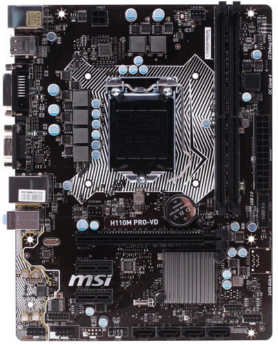
Thank you for purchasing the MSI
PRO-VD/ H110M PRO-VH/ H110M
gives information about board layout, component overview
and BIOS setup.
Contents
Safety Information ……………………………………………………………………………….. 2
Specifications ……………………………………………………………………………………… 3
Rear I/O Panel ……………………………………………………………………………………… 6
LAN Port LED Status Table ……………………………………………………………………..6
Overview of Components ……………………………………………………………………. 7
CPU Socket …………………………………………………………………………………………..8
DIMM Slots ……………………………………………………………………………………………9
JPWR1~2: Power Connectors ………………………………………………………………..11
JUSB1: USB 2.0 Connector ……………………………………………………………………11
CPUFAN1, SYSFAN1: Fan Connectors …………………………………………………..13
BIOS Setup ………………………………………………………………………………………… 16
Entering BIOS Setup……………………………………………………………………………..16
Resetting BIOS …………………………………………………………………………………….17
Updating BIOS ……………………………………………………………………………………..17
Software Description …………………………………………………………………………. 18
Installing Drivers …………………………………………………………………………………..18
Installing Utilities …………………………………………………………………………………..18
7/ 8.1/ 10 …………………………………………………………………18
®
motherboard
®
PRO-D. This User Guide
H110M
Contents
1
Chapters
Summary of Contents for MSI H110M PRO-VD
- Каталог
- Комплектующие для ПК
- Основные комплектующие для ПК
- Материнские платы
- MSI
- Плата MSI LGA1151 H110 H110M PRO-VD 2xDDR4 1xPCI-Ex16 DVI/Dsub SATA3 USB3.1 mATX
- Инструкции и файлы
Плата MSI LGA1151 H110 H110M PRO-VD 2xDDR4 1xPCI-Ex16 DVI/Dsub SATA3 USB3.1 mATX

75
Код товара: 1037743
Плата MSI LGA1151 H110 H110M PRO-VD 2xDDR4 1xPCI-Ex16 DVI/Dsub SATA3 USB3.1 mATX

Характеристики
Отзывы75Обзоры1Инструкции и файлы2
Как выбрать?
Советуют эксперты DNS
Инструкции и файлы для Плата MSI LGA1151 H110 H110M PRO-VD 2xDDR4 1xPCI-Ex16 DVI/Dsub SATA3 USB3.1 mATX
-
Инструкция: Материнская плата MSI H110M PRO-VD (MULTI)Русский8.3 Мб
Мы рекомендуем скачивать драйверы с официального сайта производителя.Ссылка на официальный сайт. Материнская плата MSI H110M PRO-VD
Нашли ошибку?
Выделите текст с ошибкой и нажмите Ctrl+Enter или
напишите нам
.
Указанное предложение действительно на 23.09.2023
![]()
Thank you for purchasing the MSI® motherboard H110M PRO-VD/ H110M PRO-VH/ H110M PRO-D. This User Guide gives information about board layout, component overview and BIOS setup.
|
Contents |
|
|
Safety Information……………………………………………………………………………….. |
2 |
|
Specifications………………………………………………………………………………………. |
3 |
|
Rear I/O Panel……………………………………………………………………………………… |
6 |
|
LAN Port LED Status Table……………………………………………………………………… |
6 |
|
Overview of Components……………………………………………………………………. |
7 |
|
CPU Socket…………………………………………………………………………………………… |
8 |
|
DIMM Slots……………………………………………………………………………………………. |
9 |
|
PCI_E1~3: PCIe Expansion Slots…………………………………………………………….. |
9 |
|
SATA1~4: SATA 6Gb/s Connectors………………………………………………………… |
10 |
|
JFP1, JFP2: Front Panel Connectors………………………………………………………. |
10 |
|
JPWR1~2: Power Connectors………………………………………………………………… |
11 |
|
JUSB1: USB 2.0 Connector…………………………………………………………………… |
11 |
|
JUSB3: USB 3.1 Gen1 Connector…………………………………………………………… |
12 |
|
JAUD1: Front Audio Connector………………………………………………………………. |
12 |
|
JCOM1: Serial Port Connector……………………………………………………………….. |
12 |
|
CPUFAN1, SYSFAN1: Fan Connectors…………………………………………………… |
13 |
|
JTPM1: TPM Module Connector…………………………………………………………….. |
14 |
|
JCI1: Chassis Intrusion Connector………………………………………………………….. |
14 |
|
JBAT1: Clear CMOS (Reset BIOS) Jumper……………………………………………… |
15 |
|
EZ Debug LED: Debug LED indicators……………………………………………………. |
15 |
|
BIOS Setup………………………………………………………………………………………… |
16 |
|
Entering BIOS Setup…………………………………………………………………………….. |
16 |
|
Resetting BIOS…………………………………………………………………………………….. |
17 |
|
Updating BIOS……………………………………………………………………………………… |
17 |
|
Software Description…………………………………………………………………………. |
18 |
|
Installing Windows® 7/ 8.1/ 10………………………………………………………………… |
18 |
|
Installing Drivers…………………………………………………………………………………… |
18 |
|
Installing Utilities…………………………………………………………………………………… |
18 |
Contents 1
Safety Information
●●The components included in this package are prone to damage from electrostatic discharge (ESD). Please adhere to the following instructions to ensure successful computer assembly.
●●Ensure that all components are securely connected. Loose connections may cause the computer to not recognize a component or fail to start.
●●Hold the motherboard by the edges to avoid touching sensitive components.
●●It is recommended to wear an electrostatic discharge (ESD) wrist strap when handling the motherboard to prevent electrostatic damage. If an ESD wrist strap is not available, discharge yourself of static electricity by touching another metal object before handling the motherboard.
●●Store the motherboard in an electrostatic shielding container or on an anti-static pad whenever the motherboard is not installed.
●●Before turning on the computer, ensure that there are no loose screws or metal components on the motherboard or anywhere within the computer case.
●●Do not boot the computer before installation is completed. This could cause permanent damage to the components as well as injury to the user.
●●If you need help during any installation step, please consult a certified computer technician.
●●Always turn off the power supply and unplug the power cord from the power outlet before installing or removing any computer component.
●●Keep this user guide for future reference. ●●Keep this motherboard away from humidity.
●●Make sure that your electrical outlet provides the same voltage as is indicated on the PSU, before connecting the PSU to the electrical outlet.
●●Place the power cord such a way that people can not step on it. Do not place anything over the power cord.
●●All cautions and warnings on the motherboard should be noted.
●●If any of the following situations arises, get the motherboard checked by service personnel:
Liquid has penetrated into the computer.
The motherboard has been exposed to moisture.
The motherboard does not work well or you can not get it work according to user guide.
The motherboard has been dropped and damaged.The motherboard has obvious sign of breakage.
●●Do not leave this motherboard in an environment above 60°C (140°F), it may damage the motherboard.
2 Safety Information

Specifications
|
CPU |
Supports 6th Gen Intel® Core™ i3/i5/i7 processors, and Intel® |
|
|
Pentium® and Celeron® processors for Socket LGA1151 |
||
|
Chipset |
●●Intel® H110 Chipset |
|
|
●●2x DDR4 memory slots, support up to 32GB |
||
|
Supports DDR4 2133 MHz |
||
|
Memory |
●●Dual channel memory architecture |
|
|
●●Supports non-ECC, un-buffered memory |
||
|
●●Supports Intel® Extreme Memory Profile (XMP) |
||
|
Expansion Slots |
●●1x PCIe 3.0 x16 slot |
|
|
●●2x PCIe 2.0×1 slots |
||
|
●●1x HDMI™ port, supports a maximum resolution of |
||
|
4096×2160@24Hz, 2560×1600@60Hz (H110M PRO-VH) |
||
|
Onboard |
●●1x DVI-D port, supports a maximum resolution of |
|
|
1920×1200@60Hz (H110M PRO-VD/ H110M PRO-D) |
||
|
Graphics |
||
|
●●1x VGA port, supports a maximum resolution of |
||
|
2048×1536@50Hz, 2048×1280@60Hz, 1920×1200@60Hz |
||
|
(H110M PRO-VH/ H110M PRO-VD) |
||
|
Storage |
Intel® H110 Chipset |
|
|
●●4x SATA 6Gb/s ports |
||
|
●●Intel® H110 Chipset |
||
|
4x USB 3.1 Gen1 (SuperSpeed USB) ports (2 ports on |
||
|
the back panel, 2 ports available through the internal USB |
||
|
USB |
connector) |
|
|
6x USB 2.0 (High-speed USB) ports (4 ports on the |
||
|
back panel, 2 ports available through the internal USB |
||
|
connectors) |
||
|
Audio |
●●Realtek® ALC887 Codec |
|
|
●●7.1-Channel High Definition Audio |
||
|
LAN |
1x Realtek® RTL8111H Gigabit LAN controller |
|
|
Continued on next page |
Specifications 3

|
Continued from previous page |
||
|
●●1x PS/2 keyboard/ mouse combo port |
||
|
●●4x USB 2.0 ports |
||
|
●●1x HDMI™ port (H110M PRO-VH) |
||
|
Back Panel |
●●1x DVI-D port (H110M PRO-VD/ H110M PRO-D) |
|
|
Connectors |
●●1x VGA port (H110M PRO-VH/ H110M PRO-VD) |
|
|
●●1x LAN (RJ45) port |
||
|
●●2x USB 3.1 Gen1 ports |
||
|
●●3x audio jacks |
||
|
●●1x 24-pin ATX main power connector |
||
|
●●1x 4-pin ATX 12V power connector |
||
|
●●4x SATA 6Gb/s connectors |
||
|
●●1x USB 2.0 connector (supports additional 2 USB 2.0 ports) |
||
|
●●1x USB 3.1 Gen1 connector (supports additional 2 USB 3.1 |
||
|
Gen1 ports) |
||
|
Internal |
●●1x 4-pin CPU fan connector |
|
|
Connectors |
●●1x 4-pin system fan connector |
|
|
●●1x Front panel audio connector |
||
|
●●2x Front panel connectors |
||
|
●●1x TPM module connector |
||
|
●●1x Serial Port connector |
||
|
●●1x Chassis Intrusion connector |
||
|
●●1x Clear CMOS jumper |
||
|
I/O Controller |
NUVOTON NCT5563D Controller Chip |
|
|
●●CPU/System temperature detection |
||
|
Hardware Monitor |
●●CPU/System fan speed detection |
|
|
●●CPU/System fan speed control |
||
|
Form Factor |
●●Micro-ATX Form Factor |
|
|
●●9.3 in. x 7.1 in. (23.5 cm x 18.0 cm) |
||
|
●●1x 64 Mb flash |
||
|
BIOS Features |
●●UEFI AMI BIOS |
|
|
●●ACPI 5.0, PnP 1.0a, SM BIOS 2.8 |
||
|
●●Multi-language |
||
|
Continued on next page |
4 Specifications
Continued from previous page
|
●●Drivers |
|
|
●●COMMAND CENTER |
|
|
●●LIVE UPDATE 6 |
|
|
●●FAST BOOT |
|
|
●●SUPER CHARGER |
|
|
●●M-CLOUD |
|
|
Software |
●●RAMDISK |
|
●●Intel® Small Business Basics |
|
|
●●NETWORK GENIE |
|
|
●●Intel® Extreme Tuning Utility |
|
|
●●Norton™ Security |
|
|
●●Google Chrome™,Google Toolbar, Google Drive |
|
|
●●CPU-Z |
Specifications 5
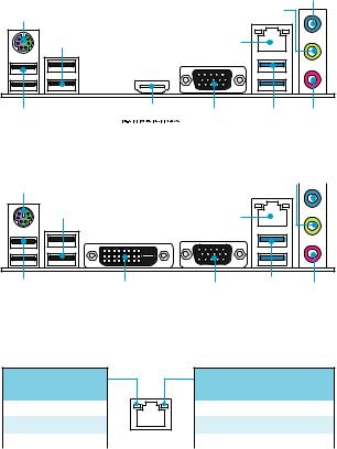
Rear I/O Panel
|
H110M PRO-VH |
Line-in |
|
PS/2 |
Line-out |
|
USB 2.0 |
LAN |
USB 2.0 

 VGA USB 3.1 Gen1 Mic in
|
H110M PRO-VD/ H110M PRO-D |
Line-in |
||||
|
PS/2 |
Line-out |
||||
|
USB 2.0 |
DVI-D |
VGA |
USB 3.1 Gen1 Mic in |
|
(H110M PRO-VD) |
LAN Port LED Status Table
Link/ Activity LED
|
Status |
Description |
|
Off |
No link |
|
Yellow |
Linked |
|
Blinking |
Data activity |
Speed LED
|
Status |
Description |
|
Off |
10 Mbps connection |
|
Green |
100 Mbps connection |
|
Orange |
1 Gbps connection |
6 Rear I/O Panel
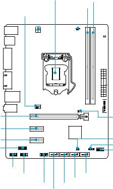
Overview of Components
PCI_E1
PCI_E2
PCI_E3 JTPM1
|
CPU Socket |
DIMM2 |
|||||||
|
JPWR2 |
DIMM1 |
|||||||
|
SYSFAN1 |
CPUFAN1 |
|||||||
 EZ Debug LED

 JPWR1
JPWR1
 JUSB3
JUSB3
JBAT1
JCI1
JFP2
JFP1
JAUD1
JCOM1 SATA1
SATA2
JUSB1 SATA3
SATA4
Overview of Components 7

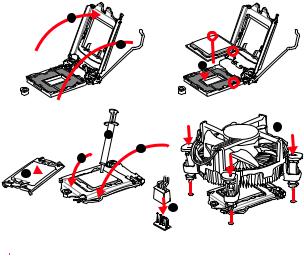
CPU Socket
Please install the CPU into the CPU socket as shown below.
2
1
3


8
7
5 4
6


9
 Important
●●Always unplug the power cord from the power outlet before installing or removing the CPU.
●●Please retain the CPU protective cap after installing the processor. MSI will deal with Return Merchandise Authorization (RMA) requests if only the motherboard comes with the protective cap on the CPU socket.
●●When installing a CPU, always remember to install a CPU heatsink. A CPU heatsink is necessary to prevent overheating and maintain system stability.
●●Confirm that the CPU heatsink has formed a tight seal with the CPU before booting your system.
●●Overheating can seriously damage the CPU and motherboard. Always make sure the cooling fans work properly to protect the CPU from overheating. Be sure to apply an even layer of thermal paste (or thermal tape) between the CPU and the heatsink to enhance heat dissipation.
●●Whenever the CPU is not installed, always protect the CPU socket pins by covering the socket with the plastic cap.
●●If you purchased a separate CPU and heatsink/ cooler, Please refer to the documentation in the heatsink/ cooler package for more details about installation.
8 Overview of Components

DIMM Slots
Please install the memory module into the DIMM slot as shown below.
1
3
 Important
●●Due to chipset resource usage, the available capacity of memory will be a little less than the amount of installed.
●●Please note that the maximum capacity of addressable memory is 4GB or less for 32-bit Windows OS due to the memory address limitation. Therefore, we
recommended that you to install 64-bit Windows OS if you want to install more than 4GB memory on the motherboard.
PCI_E1~3: PCIe Expansion Slots
PCI_E1: PCIe 3.0 x16 slot
PCI_E2: PCIe 2.0×1 slot
PCI_E3: PCIe 2.0×1 slot
 Important
When adding or removing expansion cards, always turn off the power supply and unplug the power supply power cable from the power outlet. Read the expansion card’s documentation to check for any necessary additional hardware or software changes.
Overview of Components 9
SATA1~4: SATA 6Gb/s Connectors
These connectors are SATA 6Gb/s interface ports. Each connector can connect to one SATA device.
SATA4
SATA3
SATA2
SATA1
 Important
●●Please do not fold the SATA cable at a 90-degree angle. Data loss may result during transmission otherwise.
●●SATA cable has identical plugs on either sides of the cable. However, it is recommended that the flat connector be connected to the motherboard for space saving purposes.
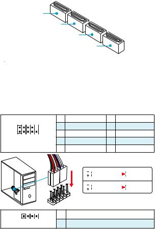
JFP1, JFP2: Front Panel Connectors
These connectors connect to the switches and LEDs on the front panel.
|
2 |
10 |
1 |
HDD LED + |
2 |
Power LED + |
|
|
3 |
HDD LED — |
4 |
Power LED — |
|||
|
1 |
9 |
5 |
Reset Switch |
6 |
Power Switch |
|
|
7 |
Reset Switch |
8 |
Power Switch |
|||
|
JFP1 |
||||||
|
9 |
Reserved |
10 |
No Pin |
|||
|
HDDLED RESETSW |
||
|
JFP1 |
||
|
1 |
1 |
|
|
JFP2 |
3 |
|
|
HDD LED |
HDD LED — |
||||||
|
HDD LED + |
|||||||
|
POWER LED — |
|||||||
|
POWER LED |
POWER LED + |
||||||
|
Speaker — |
2 |
Buzzer + |
|
Buzzer — |
4 |
Speaker + |
10 Overview of Components
![]()
JPWR1~2: Power Connectors
These connectors allow you to connect an ATX power supply.
|
1 |
+3.3V |
13 |
+3.3V |
||||||||
|
2 |
+3.3V |
14 |
-12V |
||||||||
|
12 |
24 |
3 |
Ground |
15 |
Ground |
||||||
|
4 |
+5V |
16 |
PS-ON# |
||||||||
|
5 |
Ground |
17 |
Ground |
||||||||
|
JPWR1 |
6 |
+5V |
18 |
Ground |
|||||||
|
7 |
Ground |
19 |
Ground |
||||||||
|
8 |
PWR OK |
20 |
Res |
||||||||
|
1 |
13 |
9 |
5VSB |
21 |
+5V |
||||||
|
10 |
+12V |
22 |
+5V |
||||||||
|
11 |
+12V |
23 |
+5V |
||||||||
|
12 |
+3.3V |
24 |
Ground |
||||||||
|
4 |
3 |
JPWR2 |
1 |
Ground |
3 |
+12V |
|||||
|
2 |
1 |
2 |
Ground |
4 |
+12V |
||||||
 Important
Make sure that all the power cables are securely connected to a proper ATX power supply to ensure stable operation of the motherboard.
JUSB1: USB 2.0 Connector
This connector allows you to connect USB 2.0 ports on the front panel.
|
1 |
VCC |
2 |
VCC |
|||||||
|
2 |
10 |
3 |
USB0- |
4 |
USB1- |
|||||
|
5 |
USB0+ |
6 |
USB1+ |
|||||||
|
1 |
9 |
7 |
Ground |
8 |
Ground |
|||||
|
9 |
No Pin |
10 |
NC |
 Important
●●Note that the VCC and Ground pins must be connected correctly to avoid possible damage.
●●In order to recharge your iPad,iPhone and iPod through USB ports, please install MSI® SUPER CHARGER utility.
Overview of Components 11

JUSB3: USB 3.1 Gen1 Connector
This connector allows you to connect USB 3.1 Gen1 ports on the front panel.
|
1 |
Power |
11 |
USB2.0+ |
|||
|
2 |
USB3_RX_DN |
12 |
USB2.0- |
|||
|
10 |
3 |
USB3_RX_DP |
13 |
Ground |
||
|
11 |
||||||
|
4 |
Ground |
14 |
USB3_TX_C_DP |
|||
|
5 |
USB3_TX_C_DN |
15 |
USB3_TX_C_DN |
|||
|
6 |
USB3_TX_C_DP |
16 |
Ground |
|||
|
7 |
Ground |
17 |
USB3_RX_DP |
|||
|
1 |
20 |
8 |
USB2.0- |
18 |
USB3_RX_DN |
|
|
9 |
USB2.0+ |
19 |
Power |
|||
|
10 |
Ground |
20 |
No Pin |
 Important
Note that the Power and Ground pins must be connected correctly to avoid possible damage.
JAUD1: Front Audio Connector
This connector allow you to connect audio jacks on the front panel.
|
1 |
MIC L |
2 |
Ground |
|||||||
|
2 |
10 |
3 |
MIC R |
4 |
NC |
|||||
|
5 |
Head Phone R |
6 |
MIC Detection |
|||||||
|
1 |
9 |
7 |
SENSE_SEND |
8 |
No Pin |
|||||
|
9 |
Head Phone L |
10 |
Head Phone Detection |
JCOM1: Serial Port Connector
This connector allows you to connect the optional serial port with bracket.
|
1 |
DCD |
2 |
SIN |
|||||||
|
2 |
10 |
3 |
SOUT |
4 |
DTR |
|||||
|
5 |
Ground |
6 |
DSR |
|||||||
|
1 |
9 |
7 |
RTS |
8 |
CTS |
|||||
|
9 |
RI |
10 |
No Pin |
12 Overview of Components
CPUFAN1, SYSFAN1: Fan Connectors
Fan connectors can be classified as PWM (Pulse Width Modulation) Mode and Voltage Mode. PWM Mode fan connectors provide constant 12V output and adjust fan speed with speed control signal. Voltage Mode fan connectors control fan speed by changing voltage. Therefore, when you plug a 3-pin (Non-PWM) fan to a PWM Mode fan connector, the fan speed will be always maintained at 100%, and that could be noisy.
|
PWM Mode fan connector |
Voltage Mode fan connector |
|||||||||||||||
|
1 |
1 |
|||||||||||||||
|
CPUFAN1 |
SYSFAN1 |
|||||||||||||||
|
1 |
Ground |
2 |
+12V |
1 |
Ground |
2 |
Voltage |
|||||||||
|
Control |
||||||||||||||||
|
3 |
Sense |
4 |
Speed Control |
|||||||||||||
|
3 |
Sense |
4 |
NC |
|||||||||||||
|
Signal |
||||||||||||||||
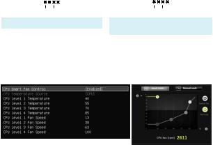
Controlling the fan speed
There are two ways to manage fan speed. One is to go to BIOS > Advanced > Hardware Monitor. The other is to use COMMAND CENTER application.
BIOS > Advanced > Hardware Monitor
COMMAND CENTER
BIOS Hardware Monitor sub-menu allows you to set the temperature levels and the corresponding fan speed levels.
COMMAND CENTER offers gradient points of the fan speed that allow you to adjust fan speed in relation to CPU temperature.
Overview of Components 13

JTPM1: TPM Module Connector
This connector is for TPM (Trusted Platform Module). Please refer to the TPM security platform manual for more details and usages.
|
1 |
LPC Clock |
2 |
3V Standby power |
|||||||||
|
3 |
LPC Reset |
4 |
3.3V Power |
|||||||||
|
2 |
14 |
5 |
LPC address & data pin0 |
6 |
Serial IRQ |
|||||||
|
7 |
LPC address & data pin1 |
8 |
5V Power |
|||||||||
|
1 |
13 |
9 |
LPC address & data pin2 |
10 |
No Pin |
|||||||
|
11 |
LPC address & data pin3 |
12 |
Ground |
|||||||||
|
13 |
LPC Frame |
14 |
Ground |
JCI1: Chassis Intrusion Connector
This connector allows you to connect the chassis intrusion switch cable.
|
Normal |
Trigger the chassis |
|||
|
(default) |
intrusion event |
Using chassis intrusion detector
1.Connect the JCI1 connector to the chassis intrusion switch/ sensor on the chassis.
2.Close the chassis cover.
3.Go to BIOS > Security > Chassis Intrusion Configuration.
4.Set Chassis Intrusion to Enabled.
5.Press F10 to save and exit and then press the Enter key to select Yes.
6.Once the chassis cover is opened again, a warning message will be displayed on screen when the computer is turned on.
Resetting the chassis intrusion warning
1.Go to BIOS > Security > Chassis Intrusion Configuration.
2.Set Chassis Intrusion to Reset.
3.Press F10 to save and exit and then press the Enter key to select Yes.
14 Overview of Components

JBAT1: Clear CMOS (Reset BIOS) Jumper
There is CMOS memory onboard that is external powered from a battery located on the motherboard to save system configuration data. If you want to clear the system configuration, set the jumpers to clear the CMOS memory.
|
Keep Data |
Clear CMOS/ |
|||
|
(default) |
Reset BIOS |
Resetting BIOS to default values
1.Power off the computer and unplug the power cord
2.Use a jumper cap to short JBAT1 for about 5-10 seconds.
3.Remove the jumper cap from JBAT1.
4.Plug the power cord and power on the computer.
EZ Debug LED: Debug LED indicators
These LEDs indicate the status of the motherboard.

 CPU — indicates CPU is not detected or fail.

 DRAM — indicates DRAM is not detected or fail.

 VGA — indicates GPU is not detected or fail.
Overview of Components 15
BIOS Setup
The default settings offer the optimal performance for system stability in normal conditions. You should always keep the default settings to avoid possible system damage or failure booting unless you are familiar with BIOS.
 Important
●●BIOS items are continuous update for better system performance. Therefore, the description may be slightly different from the latest BIOS and should be held for reference only. You could also refer to the HELP information panel for BIOS item description.
●●The pictures in this chapter are for reference only and may vary from the product you purchased.
Entering BIOS Setup
Please refer the following methods to enter BIOS setup.
●●Press Delete key, when the Press DEL key to enter Setup Menu, F11 to enter Boot Menu message appears on the screen during the boot process.
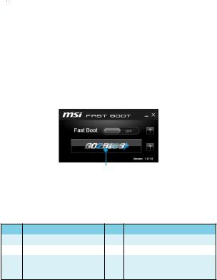
●●Use MSI FAST BOOT application. Click on GO2BIOS button and choose OK. The system will reboot and enter BIOS setup directly.
Click on GO2BIOS
●●Enable the GO2BIOS item (Boot > GO2BIOS) in BIOS setup. It allows the system to enter BIOS setup directly by pressing the power button for 4 seconds upon bootup.
Function key
|
Key |
Function |
Key |
Function |
|
F1 |
General Help |
F4 |
Enter CPU Specifications menu |
|
F5 |
Enter Memory-Z menu |
F6 |
Load optimized defaults |
|
Take a screenshot and save it |
|||
|
F10 |
Save Change and Reset* |
F12 |
to USB flash drive (FAT/ FAT32 |
|
format only). |
* When you press F10, a confirmation window which provides the modification information appears. Select between Yes or No to confirm your choice.
16 BIOS Setup

Resetting BIOS
You might need to restore the default BIOS setting to solve certain problems. There are several ways to reset BIOS:
●●Go to BIOS and press F6 to load optimized defaults. ●●Short the Clear CMOS jumper on the motherboard.
 Important
Please refer to the Clear CMOS Jumper section for resetting BIOS.
Updating BIOS
Updating BIOS with M-FLASH
Before updating:
Please download the latest BIOS file that matches your motherboard model from MSI website. And then save the BIOS file into the USB flash drive.
Updating BIOS:
1.Insert the USB flash drive that contains the update file into the computer.
2.Reboot the system, and then press Del key to enter the BIOS Setup during POST.
3.Go to BIOS > M-FLASH > Select one file to update BIOS and ME, select a BIOS file to perform the BIOS update process.
4.After the flashing process is 100% complete, the system will reboot.
Updating the BIOS with Live Update 6
Before updating:
Make sure the LAN driver is already installed and the internet connection is set properly.
Updating BIOS:
1.Install and launch MSI LIVE UPDATE 6.
2.Select Manual scan.
3.Check MB BIOS box and click on Scan button.
|
4. Select the MB BIOS and click on |
icon to download and install the latest BIOS |
|
file. |
5.Click Next and choose In Windows mode. And then click Next and Start to start updating BIOS.
6.After the flashing process is 100% completed, the system will restart automatically.
BIOS Setup 17
Software Description
Installing Windows® 7/ 8.1/ 10
1.Power on the computer.
2.Insert the Windows® 7/ 8.1/ 10 disc into your optical drive.
Note: Due to chipset limitation, during the Windows® 7 installation process, USB optical drives or USB pen drives are not supported.
3.Press the Restart button on the computer case.
4.For windows 8.1/ 10, skip this step. For Windows 7, access the BIOS menu
Advanced > Windows OS Configuration > Windows 7 Installation and set the item to enabled, save changes and restart.
Note: It is suggested to plug in your USB Keyboard/USB Mouse to the leftmost USB port when installing Windows 7.
5.Press F11 key during the computer POST (Power-On Self Test) to get into Boot Menu.
6.Select your optical drive from the Boot Menu.
7.Press any key when screen shows Press any key to boot from CD or DVD…
message.
8.Follow the instructions on the screen to install Windows® 7/ 8.1/ 10.
Installing Drivers
1.Start up your computer in Windows® 7/ 8.1/ 10.
2.Insert MSI® Driver Disc into your optical drive.
3.The installer will automatically appear and it will find and list all necessary drivers.
4.Click Install button.
5.The software installation will then be in progress, after it has finished it will prompt you to restart.
6.Click OK button to finish.
7.Restart your computer.
Installing Utilities
Before you install utilities, you must complete drivers installation.
1.Insert MSI® Driver Disc into your optical drive.
2.The installer will automatically appear.
3.Click Utilities tab.
4.Select the utilities you want to install.
5.Click Install button.
6.The utilities installation will then be in progress, after it has finished it will prompt you to restart.
7.Click OK button to finish.
8.Restart your computer.
18 Software Description

MSI® H110M PRO-VD/ H110M PRO-VH/ H110M PRO-D
., , BIOS.
|
………………………………………………………………………………………………. |
2 |
|
……………………………………………………………………………………………………… |
3 |
|
I/O …………………………………………………………………………………………. |
6 |
|
LAN LED …………………………………………………………………………. |
6 |
|
……………………………………………………………………………………………………… |
7 |
|
CPU ………………………………………………………………………………………………. |
8 |
|
DIMM …………………………………………………………………………………………….. |
9 |
|
PCI_E1~3: PCIe ………………………………………………………………………. |
9 |
|
SATA1~4: SATA 6Gb/s ………………………………………………………………. |
10 |
|
JFP1, JFP2: ………………………………………………………………… |
10 |
|
JPWR1~2: …………………………………………………………………………. |
11 |
|
JUSB1: USB 2.0 ………………………………………………………………………… |
11 |
|
JUSB3: USB 3.1 Gen1 ……………………………………………………………….. |
12 |
|
JAUD1: …………………………………………………………………… |
12 |
|
JCOM1: …………………………………………………………………… |
12 |
|
CPUFAN1, SYSFAN1: ……………………………………………………………. |
13 |
|
JTPM1: TPM ………………………………………………………………………. |
14 |
|
JCI1: ………………………………………………………………………….. |
14 |
|
JBAT1: CMOS (Reset BIOS) ………………………………………………… |
15 |
|
EZ Debug LED: LED ………………………………………………………… |
15 |
|
BIOS …………………………………………………………………………………………… |
16 |
|
BIOS ……………………………………………………………………………… |
16 |
|
BIOS ……………………………………………………………………………………………. |
17 |
|
BIOS ……………………………………………………………………………………… |
17 |
|
………………………………………………………………………………….. |
18 |
|
Windows® 7/ 8.1/ 10 ………………………………………………………………… |
18 |
|
………………………………………………………………………………… |
18 |
|
………………………………………………………………………………… |
18 |
1
●● (ESD) .
●● . ,.
●● .
●● (ESD). ESD ,.
●● .
●● .
●● . ,.
●● .
●● .
●● . ●● .
●●PSU PSU.
●● ..
●● . ●● , .
. .
않습니다.
.
.
●● 60°C (140°F) ..
2
![]()
|
CPU |
6 Gen Intel® Core™ i3/i5/i7 LGA1151 |
|
|
Intel® Pentium® Celeron® . |
||
|
●●Intel® H110 |
||
|
●●DDR4 2 , 32GB |
||
|
DDR4 2133 MHz |
||
|
●● |
||
|
●●non-ECC, un-buffered |
||
|
●●Intel® Extreme Memory Profile (XMP) |
||
|
●●PCIe 3.0 x16 1 |
||
|
●●PCIe 2.0×1 2 |
||
|
●●HDMI™ 1 , 4096×2160@24Hz, |
||
|
2560×1600@60Hz (H110M PRO-VH) |
||
|
●●DVI-D 1 , 1920×1200@60Hz |
||
|
(H110M PRO-VD/ H110M PRO-D) |
||
|
●●VGA 1 , 2048×1536@50Hz, 2048×1280@60Hz, |
||
|
1920×1200@60Hz (H110M PRO-VH/ H110M |
||
|
PRO-VD) |
||
|
Intel® H110 |
||
|
●●SATA 6Gb/s 4 |
||
|
●●Intel® H110 |
||
|
USB |
USB 3.1 Gen1 (SuperSpeed USB) 4 ( |
|
|
2 , USB 2 ) |
||
|
USB 2.0 (High-speed USB) 6 ( 4 |
||
|
, USB 2 ) |
||
|
●●Realtek® ALC887 |
||
|
●●7.1- HD |
||
|
LAN |
Realtek RTL8111H Gigabit LAN 1 |
|
3

●●PS/2 / 1 ●●USB 2.0 4
●●HDMI™ 1 (H110M PRO-VH)
●●DVI-D 1 (H110M PRO-VD/ H110M PRO-D) ●●VGA 1 (H110M PRO-VH/ H110M PRO-VD)
●●LAN (RJ45) 1 ●●USB 3.1 Gen1 2 ●● 3
●●24 ATX 1
●●4 ATX 12V 1 ●●SATA 6Gb/s 4
●●USB 2.0 1 ( USB 2.0 2 )
●●USB 3.1 Gen1 1 ( USB 3.1 Gen1 2 ) ●●4- CPU 1
●●4- 1 ●● 1 ●● 2
●●TPM 1 ●● 1 ●● 1 ●●CMOS 1
I/O NUVOTON NCT5563D
●●CPU/●●CPU/
●●CPU/
|
●●Micro-ATX |
||
|
●●9.3 in. x 7.1 in. (23.5 cm x 18.0 cm) |
||
|
●●64 Mb 1 |
||
|
BIOS |
●●UEFI AMI BIOS |
|
|
●●ACPI 5.0, PnP 1.0a, SM BIOS 2.8 |
||
|
●● |
||
4
|
●● |
|
|
●●COMMAND CENTER |
|
|
●●LIVE UPDATE 6 |
|
|
●●FAST BOOT |
|
|
●●SUPER CHARGER |
|
|
●●M-CLOUD |
|
|
●●RAMDISK |
|
|
●●Intel® Small Business Basics |
|
|
●●NETWORK GENIE |
|
|
●● ® |
|
|
●●Norton™ |
|
|
●●Google Chrome™,Google Toolbar, Google Drive |
|
|
●●CPU-Z |
5

I/O
|
H110M PRO-VH |
|
|
PS/2 |
|
|
USB 2.0 |
LAN |
|
USB 2.0 |
VGA |
USB 3.1 Gen1 |
|
|
H110M PRO-VD/ H110M PRO-D |
|||
|
PS/2 |
|||
|
USB 2.0 |
LAN |
||
|
USB 2.0 |
DVI-D |
VGA |
USB 3.1 Gen1 |
(H110M PRO-VD)
LAN LED
LED
|
10 Mbps |
||
|
. |
||
|
100 Mbps |
||
|
. |
||
|
1 Gbps |
||
|
. |
6 I/O

PCI_E1
PCI_E2
PCI_E3 JTPM1
|
CPU |
DIMM2 |
||||||||
|
JPWR2 |
DIMM1 |
||||||||
|
SYSFAN1 |
CPUFAN1 |
||||||||
 EZ Debug LED

 JPWR1
JPWR1
 JUSB3
JUSB3
JBAT1
JCI1
JFP2
JFP1
JAUD1
JCOM1 SATA1
SATA2
JUSB1 SATA3
SATA4
7
CPU
CPU CPU .
2
1
3


8
7
5 4
6


9

●●CPU .
●● , CPU . CPU MSI (RMA).
●●CPU , CPU . CPU.
●● CPU .
●● CPU CPU. CPU( ) .
●●CPU , CPU.
●●CPU / ,/ .
8

DIMM
DIMM .
1
3

●● .
●● 4GB 32- (Windows OS) . 4GB
64Windows OS .
PCI_E1~3: PCIe
PCI_E1: PCIe 3.0 x16
PCI_E2: PCIe 2.0×1
PCI_E3: PCIe 2.0×1

뽑으세요. .
9

SATA1~4: SATA 6Gb/s
SATA 6Gb/s . SATA.
SATA4
SATA3
SATA2
SATA1

●●SATA 90 . ,.
●●SATA .
JFP1, JFP2:
LED .
|
2 |
10 |
1 |
HDD LED + |
2 |
Power LED + |
|
|
3 |
HDD LED — |
4 |
Power LED — |
|||
|
1 |
9 |
5 |
Reset Switch |
6 |
Power Switch |
|
|
7 |
Reset Switch |
8 |
Power Switch |
|||
|
JFP1 |
||||||
|
9 |
Reserved |
10 |
No Pin |
|||
|
HDDLED |
RESETSW |
|
JFP1 |
|
|
1 |
1 |
|
JFP2 |
3 |
|
HDD LED |
HDD LED — |
||||||
|
HDD LED + |
|||||||
|
POWER LED — |
|||||||
|
POWER LED |
POWER LED + |
||||||
|
Speaker — |
2 |
Buzzer + |
|
Buzzer — |
4 |
Speaker + |
10
JPWR1~2:
ATX .
|
1 |
+3.3V |
13 |
+3.3V |
||||||||
|
2 |
+3.3V |
14 |
-12V |
||||||||
|
12 |
24 |
3 |
Ground |
15 |
Ground |
||||||
|
4 |
+5V |
16 |
PS-ON# |
||||||||
|
5 |
Ground |
17 |
Ground |
||||||||
|
JPWR1 |
6 |
+5V |
18 |
Ground |
|||||||
|
7 |
Ground |
19 |
Ground |
||||||||
|
8 |
PWR OK |
20 |
Res |
||||||||
|
1 |
13 |
9 |
5VSB |
21 |
+5V |
||||||
|
10 |
+12V |
22 |
+5V |
||||||||
|
11 |
+12V |
23 |
+5V |
||||||||
|
12 |
+3.3V |
24 |
Ground |
||||||||
|
4 |
3 |
JPWR2 |
1 |
Ground |
3 |
+12V |
|||||
|
2 |
1 |
2 |
Ground |
4 |
+12V |
||||||

ATX.
JUSB1: USB 2.0
USB 2.0 .
|
1 |
VCC |
2 |
VCC |
|||||||
|
2 |
10 |
3 |
USB0- |
4 |
USB1- |
|||||
|
5 |
USB0+ |
6 |
USB1+ |
|||||||
|
1 |
9 |
7 |
Ground |
8 |
Ground |
|||||
|
9 |
No Pin |
10 |
NC |

●●VCC .
●●USB iPad, iPhone iPod MSI® SUPER CHARGER
.
11
JUSB3: USB 3.1 Gen1
USB 3.1 Gen1 .
|
1 |
Power |
11 |
USB2.0+ |
|||
|
2 |
USB3_RX_DN |
12 |
USB2.0- |
|||
|
10 |
3 |
USB3_RX_DP |
13 |
Ground |
||
|
11 |
||||||
|
4 |
Ground |
14 |
USB3_TX_C_DP |
|||
|
5 |
USB3_TX_C_DN |
15 |
USB3_TX_C_DN |
|||
|
6 |
USB3_TX_C_DP |
16 |
Ground |
|||
|
7 |
Ground |
17 |
USB3_RX_DP |
|||
|
1 |
20 |
8 |
USB2.0- |
18 |
USB3_RX_DN |
|
|
9 |
USB2.0+ |
19 |
Power |
|||
|
10 |
Ground |
20 |
No Pin |

.
JAUD1:
.
|
1 |
MIC L |
2 |
Ground |
|||||||
|
2 |
10 |
3 |
MIC R |
4 |
NC |
|||||
|
5 |
Head Phone R |
6 |
MIC Detection |
|||||||
|
1 |
9 |
7 |
SENSE_SEND |
8 |
No Pin |
|||||
|
9 |
Head Phone L |
10 |
Head Phone Detection |
JCOM1:
.
|
1 |
DCD |
2 |
SIN |
|||||||
|
2 |
10 |
3 |
SOUT |
4 |
DTR |
|||||
|
5 |
Ground |
6 |
DSR |
|||||||
|
1 |
9 |
7 |
RTS |
8 |
CTS |
|||||
|
9 |
RI |
10 |
No Pin |
12
![]()
CPUFAN1, SYSFAN1:
PWM (Pulse Width Modulation) . PWM 12V.. PWM 3- (Non-PWM) ,100% .
|
PWM |
||||||||||||||||
|
1 |
1 |
|||||||||||||||
|
CPUFAN1 |
SYSFAN1 |
|||||||||||||||
|
1 |
Ground |
2 |
+12V |
1 |
Ground |
2 |
Voltage |
|||||||||
|
Control |
||||||||||||||||
|
3 |
Sense |
4 |
Speed Control |
|||||||||||||
|
3 |
Sense |
4 |
NC |
|||||||||||||
|
Signal |
||||||||||||||||
2 . BIOS > Advanced > Hardware Monitor COMMAND CENTER
.
BIOS > Advanced > Hardware Monitor
COMMAND CENTER
BIOS .
COMMAND CENTER CPU .
13

JTPM1: TPM
TPM (Trusted Platform Module) .TPM .
|
1 |
LPC Clock |
2 |
3V Standby power |
|||||||||
|
3 |
LPC Reset |
4 |
3.3V Power |
|||||||||
|
2 |
14 |
5 |
LPC address & data pin0 |
6 |
Serial IRQ |
|||||||
|
7 |
LPC address & data pin1 |
8 |
5V Power |
|||||||||
|
1 |
13 |
9 |
LPC address & data pin2 |
10 |
No Pin |
|||||||
|
11 |
LPC address & data pin3 |
12 |
Ground |
|||||||||
|
13 |
LPC Frame |
14 |
Ground |
JCI1:
.
|
( ) |
1.JCI1 / .
2..
3.BIOS > Security( ) > Chassis Intrusion Configuration( ).
4.Chassis Intrusion( ) Enabled( ) .
5.F10 . Enter Yes.
6..
1.GBIOS > Security( ) > Chassis Intrusion Configuration( )
.
2.Chassis Intrusion( ) Reset( ) .
3.F10 . Enter Yes.
14

JBAT1: CMOS (Reset BIOS)
CMOS . CMOS .
|
CMOS/ Reset |
|||||
|
( ) |
BIOS |
BIOS
2.JBAT1 5-10 .
3.JBAT1 .
4..
EZ Debug LED: LED
LED .

 CPU — CPU .

 DRAM — DRAM .
 VGA — GPU .
15

BIOS
. BIOS ,.

●●BIOS .BIOS. BIOS HELP( ) .
●● .
BIOS
BIOS .
●● DEL key to enter Setup Menu, F11 to enter Boot Menu(DEL , F11 )Delete .
●●MSI FAST BOOT . GO2BIOS OKBIOS .
GO2BIOS
●●BIOS GO2BIOS . (Boot > GO2BIOS).4 BIOS .
|
F1 |
F4 |
CPU |
|
|
F5 |
Memory-Z |
F6 |
|
|
USB |
|||
|
F10 |
* |
F12 (FAT/ FAT32 |
|
|
) |
* F10 . YesNo .
16 BIOS

BIOS
BIOS . BIOS.
●●BIOS F6 . ●● CMOS .

BIOS CMOS .
BIOS
M-FLASH BIOS
BIOS MSI® BIOSUSB .
BIOS
1.USB .
2.POST Del BIOS .
3.BIOS > M-FLASH > Select one file to update BIOS and ME , BIOS
BIOS .
4.100% .
Live Update 6 BIOS
LAN . BIOS
1.MSI LIVE UPDATE 6 .
2.Manual scan .
3.MB BIOS box Scan .
5.Next Windows mode Next Start BIOS
.
6.100% .
BIOS 17
Windows® 7/ 8.1/ 10
1..
2.Windows® 7/ 8.1/ 10 .
: Windows® 7 USB USB.
3.Restart .
4.windows 8.1/ 10 , . Windows 7 , BIOS . Advanced > Windows OS Configuration > Windows 7 Installation [ ].
: Windows 7 USB / USB.
5.POST (Power-On Self Test) F11.
6..
7.Press any key to boot from CD or DVD….
8.Windows® 7/ 8.1/ 10 .
1.Windows® 7/ 8.1/ 10 .
2.MSI® .
3..
4.Install .
5...
6.OK .
7..
.
1.MSI® .
2..
3.Utilities .
4..
5.Install .
6...
7.OK .
8..
18

Merci d’avoir acheté une carte mère MSI® H110M PRO-VD/ H110M PRO-VH/ H110M PRO-D. Ce manuel de l’utilisateur fournit des informations sur le schéma, la vue d’ensemble des composants et la configuration du BIOS.
|
Table des matières |
|
|
Informations de sécurité……………………………………………………………………… |
2 |
|
Spécifications………………………………………………………………………………………. |
3 |
|
Panneau arrière Entrée/ Sortie…………………………………………………………….. |
6 |
|
Tableau explicatif de l’état de la LED du port LAN………………………………………. |
6 |
|
Vue d’ensemble des composants……………………………………………………….. |
7 |
|
Socket processeur………………………………………………………………………………….. |
8 |
|
Slots DIMM……………………………………………………………………………………………. |
9 |
|
PCI_E1~3: Slots d’extention PCIe…………………………………………………………….. |
9 |
|
SATA1~4: Connecteurs SATA 6 Gb/s……………………………………………………… |
10 |
|
JFP1, JFP2: Connecteurs panneau avant………………………………………………… |
10 |
|
JPWR1~2: Connecteurs d’alimentation……………………………………………………. |
11 |
|
JUSB1: Connecteur USB 2.0…………………………………………………………………. |
11 |
|
JUSB3: Connecteur USB 3.1 Gen1…………………………………………………………. |
12 |
|
JAUD1: Connecteur audio avant…………………………………………………………….. |
12 |
|
JCOM1: Connecteur de port série…………………………………………………………… |
12 |
|
CPUFAN1, SYSFAN1: Connecteurs pour ventilateurs………………………………. |
13 |
|
JTPM1: Connecteur de module TPM………………………………………………………. |
14 |
|
JCI1: Connecteur intrusion châssis…………………………………………………………. |
14 |
|
JBAT1: Cavalier clear CMOS (Réinitialisation BIOS)…………………………………. |
15 |
|
EZ Debug LED: Indicateurs LED Debug………………………………………………….. |
15 |
|
Configuration du BIOS………………………………………………………………………. |
16 |
|
Entrer dans l’interface Setup du BIOS……………………………………………………… |
16 |
|
Réinitialiser le BIOS………………………………………………………………………………. |
17 |
|
Mettre le BIOS à jour…………………………………………………………………………….. |
17 |
|
Informations sur les logiciels…………………………………………………………….. |
18 |
|
Installer Windows® 7/ 8.1/ 10………………………………………………………………….. |
18 |
|
Installer les pilotes………………………………………………………………………………… |
18 |
|
Installer les utilitaires…………………………………………………………………………….. |
18 |
Table des matières 1
Informations de sécurité
●●Les composants dans l’emballage peuvent être endommagés par des décharges électrostatiques (ESD). Pour vous assurer de correctement monter votre ordinateur, veuillez vous référer aux instructions ci-dessous.
●●Assurez-vous de bien connecter tous les composants. En cas de mauvaise connexion, il se peut que l’ordinateur ne reconnaisse pas le composant et que le démarrage échoue.
●●Veuillez tenir la carte mère par les bords pour éviter de toucher les composants sensibles.
●●Il est recommandé de porter un bracelet antistatique lors de la manipulation de la carte mère pour prévenir tout dommage. Si vous n’avez pas de bracelet
antistatique, touchez un objet métallique relié à la terre avant de manipuler la carte mère afin de vous décharger de votre charge statique. Touchez régulièrement l’objet métallique pendant toute la manipulation.
●●Tant que la carte mère n’est pas installée, conservez-la dans un récipient protégé contre les ondes électrostatiques ou sur une couche antistatique.
●●Avant de démarrer l’ordinateur, vérifiez si toutes les vis et les composants métalliques sont bien fixés sur la carte mère ou ailleurs dans le boîtier de l’ordinateur.
●●Ne démarrez pas l’ordinateur avant d’avoir terminé l’installation. Ceci peut endommager les composants ou vous blesser.
●●Si vous avez besoin d’aide pendant l’installation, veuillez consulter un technicien informatique certifié.
●●Avant d’installer les composants d’ordinateur, veuillez toujours mettre hors tension et débrancher le cordon d’alimentation.
●●Gardez ce manuel pour références futures. ●●Protégez ce manuel contre l’humidité.
●●Avant de brancher le bloc d’alimentation sur la sortie électrique, veuillez vous assurer que la tension de la sortie électrique est bien égale à celle du bloc d’alimentation.
●●Placez le cordon d’alimentation de façon à éviter que l’on marche dessus. Ne posez rien sur le cordon d’alimentation.
●●Veuillez prêter attention à toutes les alertes et remarques indiquées sur la carte mère.
●●Dans un cas comme ci-dessous, faites appel au service autorisé pour vérifier votre carte mère :
Un liquide a pénétré dans l’ordinateur.
La carte mère a été exposée à de l’humidité.
La carte mère ne fonctionne pas comme indiqué dans les instructions.La carte mère est tombée par terre et a été endommagée.
La carte mère est cassée.
●●Ne pas mettre la carte mère dans un environnement dont la température est supérieure à 60°C (140°F) sous peine de l’endommager.
2 Informations de sécurité

Spécifications
|
CPU |
Support des processeurs Intel® Core™ i3/i5/i7, Intel® Pentium® |
|
|
et Celeron® de 6ème génération pour socket LGA1151 |
||
|
Chipset |
●●Chipset Intel® H110 |
|
|
●●2 x slots pour mémoire DDR4, support jusqu’à 32Go |
||
|
Support DDR4 2133 MHz |
||
|
Mémoire |
●●Architecture mémoire double canal |
|
|
●●Support non-ECC, mémoire un-buffered |
||
|
●●Support Intel® Extreme Memory Profile (XMP) |
||
|
Slots d’extension |
●●1 x slot PCIe 3.0 x16 |
|
|
●●2 x slots PCIe 2.0×1 |
||
|
●●1 x port HDMI™, supportant une résolution maximum de |
||
|
4096×2160@24Hz, 2560×1600@60Hz (H110M PRO-VH) |
||
|
Sorties vidéo |
●●1 x port DVI-D, supportant une résolution maximum de |
|
|
1920×1200@60Hz (H110M PRO-VD/ H110M PRO-D) |
||
|
intégrées |
||
|
●●1 x port VGA, supportant une résolution maximum de |
||
|
2048×1536@50Hz, 2048×1280@60Hz, 1920×1200@60Hz |
||
|
(H110M PRO-VH/ H110M PRO-VD) |
||
|
Stockage |
Chipset Intel® H110 |
|
|
●●4 x ports SATA 6 Gb/s |
||
|
●●Chipset Intel® H110 |
||
|
4 x ports USB 3.1 Gen1 (SuperSpeed USB) (2 ports sur le |
||
|
panneau arrière, 2 ports disponibles par l’intermédiaire du |
||
|
USB |
connecteur USB interne) |
|
|
6 x ports USB 2.0 High-speed USB (4 ports sur le |
||
|
panneau arrière, 2 ports disponibles par l’intermédiaire |
||
|
des connecteurs USB internes) |
||
|
Audio |
●●Codec Realtek® ALC887 |
|
|
●●Audio haute définition 7.1 |
||
|
LAN |
1 x contrôleur Realtek® RTL8111H Gigabit LAN |
|
|
Suite du tableau sur la page suivante |
Spécifications 3

Suite du tableau de la page précédente
|
●●1 x port clavier/souris PS/2 |
||
|
●●4 x ports USB 2.0 |
||
|
Connecteurs |
●●1 x port HDMI™ (H110M PRO-VH) |
|
|
●●1 x port DVI-D (H110M PRO-VD/ H110M PRO-D) |
||
|
sur le panneau |
||
|
●●1 x port VGA (H110M PRO-VH/ H110M PRO-VD) |
||
|
arrière |
||
|
●●1 x port LAN (RJ45) |
||
|
●●2 x ports USB 3.1 Gen1 |
||
|
●●3 x jacks audio |
||
|
●●1 x connecteur d’alimentation principal ATX 24 broches |
||
|
●●1 x connecteur d’alimentation ATX 12V 4 broches |
||
|
●●4 x connecteurs SATA 6 Gb/s |
||
|
●●1 x connecteur USB 2.0 (support de 2 autres ports USB |
||
|
2.0 ) |
||
|
●●1 x connecteur USB 3.1 Gen1 (support de 2 autres ports |
||
|
Connecteurs |
USB 3.1 Gen1) |
|
|
●●1 x connecteurs de ventilateurs CPU 4 broches |
||
|
internes |
||
|
●●1 x connecteurs de ventilateurs système 4 broches |
||
|
●●1 x connecteur audio avant |
||
|
●●2 x connecteurs de panneau avant |
||
|
●●1 x connecteur de module TPM |
||
|
●●1 x connecteur de port série |
||
|
●●1 x connecteur intrusion châssis |
||
|
●●1 x cavalier clear CMOS |
||
|
Contrôleur E/S |
Contrôleur NUVOTON NCT5563D |
●●Détection de la température du CPU et du système Moniteur système ●●Détection de la vitesse du ventilateur du CPU et du système
●●Contrôle de la vitesse du ventilateur du CPU et du système
|
Dimensions |
●●Format Micro-ATX |
|
|
●●23,5 cm x 18,0 cm (9,3” x 7,1”) |
||
●●1 x flash BIOS 64 Mb
Fonctions BIOS ●●BIOS UEFI AMI
●●ACPI 5.0, PnP 1.0a, SM BIOS 2.8 ●●Multilingue
Suite du tableau sur la page suivante
4 Spécifications
Suite du tableau de la page précédente
|
●●Pilotes |
|
|
●●COMMAND CENTER |
|
|
●●LIVE UPDATE 6 |
|
|
●●FAST BOOT |
|
|
●●SUPER CHARGER |
|
|
●●M-CLOUD |
|
|
Logiciel |
●●RAMDISK |
|
●●Intel® Small Business Basics |
|
|
●●NETWORK GENIE |
|
|
●●Intel® Extreme Tuning Utility |
|
|
●●Norton™ Security |
|
|
●●Google Chrome™,Google Toolbar et Google Drive |
|
|
●●CPU-Z |
Spécifications 5

Panneau arrière Entrée/ Sortie
|
H110M PRO-VH |
Ligne-in |
|
PS/2 |
Ligne-out |
|
USB 2.0 |
LAN |
USB 2.0 

 VGA USB 3.1 Gen1 Mic in
H110M PRO-VD/ H110M PRO-D Ligne-in
|
PS/2 |
Ligne-out |
|
USB 2.0 |
LAN |
|
USB 2.0 |
DVI-D |
VGA |
USB 3.1 Gen1 Mic in |
|
(H110M PRO-VD) |
Tableau explicatif de l’état de la LED du port LAN
LED indiquant la connexion et l’activité
|
Etat |
Description |
|
Eteint |
Pas de connexion |
|
Jaune |
Connexion correcte |
|
Clignote |
Activité en cours |
LED indiquant la vitesse
|
Etat |
Description |
|
Eteint |
Débit de 10 Mbps |
|
Vert |
Débit de 100 Mbps |
|
Orange |
Débit de 1 Gbps |
6 Panneau arrière Entrée/ Sortie

Vue d’ensemble des composants
PCI_E1
PCI_E2
PCI_E3 JTPM1
|
Socket processeur |
DIMM2 |
|||||||
|
JPWR2 |
DIMM1 |
|||||||
|
SYSFAN1 |
CPUFAN1 |
|||||||
 EZ Debug LED

 JPWR1
JPWR1
 JUSB3
JUSB3
JBAT1
JCI1
JFP2
JFP1
JAUD1
JCOM1 SATA1
SATA2
JUSB1 SATA3
SATA4
Vue d’ensemble des composants 7

Socket processeur
Installer le CPU dans le socket du processeur comme indiqué ci-dessous.
2
1
3


8
7
5 4
6


9
 Important
●●Avant d’installer ou de retirer le processeur du socket, veillez à toujours débrancher le câble d’alimentation de la prise électrique.
●●Veuillez garder le capot de protection du processeur après l’installation du processeur. Selon les exigences de RMA (Return Merchandise Authorization), MSI n’acceptera pas les cartes mère dont le capot de protection aura été retiré.
●●Lors de l’installation d’un processeur, n’oubliez pas d’installer un ventilateur pour processeur. Un ventilateur de processeur est nécessaire pour protéger le processeur contre la surchauffe et maintenir la stabilité du système.
●●Assurez-vous de l’étanchéité entre le ventilateur et le processeur avant de démarrer votre système.
●●La surchauffe peut facilement endommager le processeur et la carte mère. Assurez-vous toujours que le système de refroidissement fonctionne correctement pour protéger le processeur de la surchauffe. Assurez-vous d’appliquer une couche de pâte thermique (ou adhésif thermique) entre le processeur et le système de refroidissement afin d’améliorer la dissipation de la chaleur.
●●Quand le processeur n’est pas installé, protégez toujours les broches de l’emplacement du processeur avec le couvercle dédié.
●●Si vous avez achetez un processeur indépendamment du ventilateur, veuillez vous référer à la documentation dans le paquet du ventilateur pour plus d’informations concernant l’installation.
8 Vue d’ensemble des composants

Slots DIMM
Insérer le module de mémoire dans l’emplacement DIMM comme indiqué ci-dessous.
1
3
 Important
●●Du fait des ressources utilisées par le chipset, la capacité de mémoire disponible est un peu moins élevée que celle installée.
●●Veuillez noter que la capacité maximum de la mémoire est de 4 Go ou moins pour le système d’exploitation Windows 32-bit du fait de la limitation de mémoire. Par conséquent, il est recommandé d’installer le système d’exploitation Windows 64-bit si vous voulez installer une mémoire de plus de 4 Go sur la carte mère.
PCI_E1~3: Slots d’extention PCIe
PCI_E1: slot PCIe 3.0 x16
PCI_E2: slot PCIe 2.0×1
PCI_E3: slot PCIe 2.0×1
 Important
Veillez à toujours mettre l’ordinateur hors tension et à débrancher le cordon d’alimentation avant d’installer les cartes d’extension. Référez-vous à la documentation des cartes pour vérifier si un composant ou un logiciel doit être modifié.
Vue d’ensemble des composants 9
 Loading…
File Specifications:1006/1006055-h110m_provd.pdf file (11 Mar 2023) |
Accompanying Data:
MSI H110M PRO-VD Motherboard PDF Operation & User’s Manual (Updated: Saturday 11th of March 2023 11:17:19 PM)
Rating: 4.7 (rated by 13 users)
Compatible devices: H510M PRO, H270M PRO-VDH, 661FM, K8N Diamond Plus, MS-6747, K9AG Neo2-Digital, Z77A, VB9.
Recommended Documentation:
Operation & User’s Manual (Text Version):
(Ocr-Read Summary of Contents of some pages of the MSI H110M PRO-VD Document (Main Content), UPD: 11 March 2023)
-
37, 1 �…
-
81, 9 …
-
14, MSI H110M PRO-VD 14 This connector is for TPM (Trusted Platform Module). Please refer to the TPM security platform manual for more details and usages. 1 2 14 13 1 LPC Clock 2 3V Standby power 3 LPC Reset 4 3.3V Power 5 LPC address & data pin0 6 Serial IRQ 7 LPC address & data pin…
-
72, 18 ® 1. Schalten Sie den Computer ein. 2. Legen Sie die Windows ® 7/ 8.1/ 10 Disk in das optisches Laufwerk. Auf Grund einer Chipsatz-Limitierung werden während des Windows ® 7 Installationsprozesses keine optischen Laufwerke und USB-La…
-
106, 16 �…
-
65, MSI H110M PRO-VD 11 Mit diesen Anschlüssen verbinden Sie die ATX Stromstecker. 24 131 12 JPWR1 1 +3.3V 13 +3.3V 2 +3.3V 14 -12V 3 Ground 15 Ground 4 +5V 16 PS-ON# 5 Ground 17 Ground 6 +5V 18 Ground 7 Ground 19 Ground 8 PWR OK 20 Res 9 5VSB 21 +5V 10 +12V 2…
-
137, 11 24 131 12 JPWR1 1 +3.3V 13 +3.3V 2 +3.3V 14 -12V 3 Ground 15 Ground 4 +5V 16 PS-ON# 5 Ground 17 Ground 6 +5V 18 Ground 7 Ground 19 Ground 8 PWR OK 20 Res 9 5VSB 21 +5V 10 +12V 22 +5V 11 +12V 23 +5V 12 +3.3V 24 Ground 3 2 1 4 JPWR2 1 Ground 3 +12V 2 Groun…
-
125, MSI H110M PRO-VD F6 …
-
68, 14 Dieser Anschluss wird für das TPM Modul (Trusted Platform Module) verwendet. Weitere Informationen über den Einsatz des optionalen TPM Modules entnehmen Sie bitte dem TPM Plattform Handbuch. 1 2 14 13 1 LPC Clock 2 3V Standby power 3 LPC Reset 4 3.3V Power 5 LPC address &am…
-
119, 24 131 12 JPWR1 1 +3.3V 13 +3.3V 2 +3.3V 14 -12V 3 Ground 15 Ground 4 +5V 16 PS-ON# 5 Ground 17 Ground 6 +5V 18 Ground 7 Ground 19 Ground 8 PWR OK 20 Res 9 5VSB 21 +5V 10 +12V 22 +5V 11 +12V 23 +5V 12 +3.3V 24 Ground 3 2 1 4 JPWR2 1 Ground 3 +12V 2 …
-
22, MSI H110M PRO-VD 4 HDMI ™ �…
-
73, 1 2 …
-
33, 15 �…
-
8, 8 Please install the CPU into the CPU socket as shown below. Always unplug the power cord from the power outlet before installing or removing the CPU. Please retain the CPU protective cap after installing the processor. MSI will deal with Return Merchandise Authorization (RMA) requests if only the mothe…
-
32, 14 1 2 14 13 1 LPC Clock 2 3V Standby power 3 LPC Reset 4 3.3V Power 5 LPC address & data pin0 6 Serial I…
-
78, 6 …
-
15, 15 There is CMOS memory onboard that is external powered from a battery located on the motherboard to save system configuration data. If you want to clear the system configuration, set the jumpers to clear the CMOS memory. Keep Data (default) C…
-
MSI H110M PRO-VD User Manual
-
MSI H110M PRO-VD User Guide
-
MSI H110M PRO-VD PDF Manual
-
MSI H110M PRO-VD Owner’s Manuals
Recommended: HP-R4272, RCU1010, L&B LEW, DV-402
Links & Tools
Operating Impressions, Questions and Answers: