1
Quick Start
Quick Start
Thank you for purchasing the MSI® B450 TOMAHAWK MAX II motherboard. This Quick
Start section provides demonstration diagrams about how to install your computer.
Some of the installations also provide video demonstrations. Please link to the URL to
watch it with the web browser on your phone or tablet. You may have even link to the
URL by scanning the QR code.
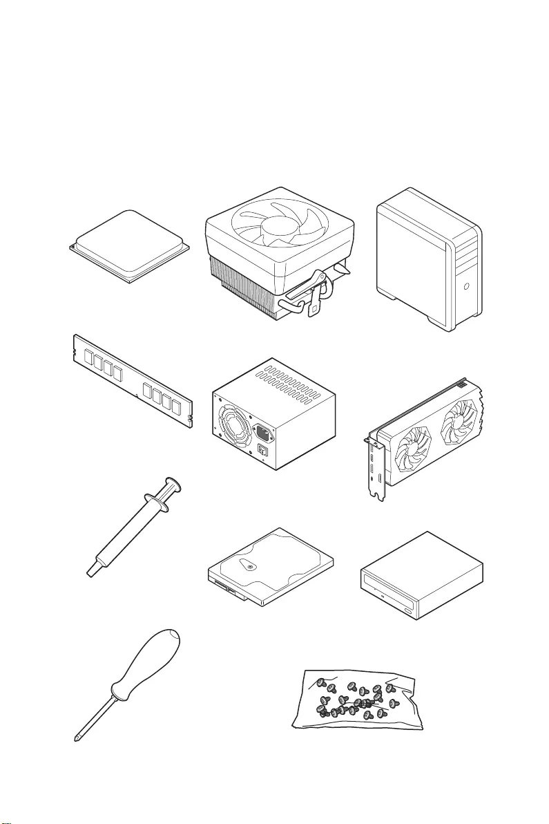
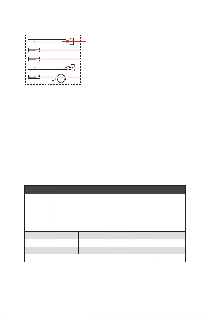
Preparing Tools and Components
DDR4 Memory
Graphics Card
SATA Hard Disk Drive SATA DVD Drive
Phillips Screwdriver
Chassis
Power Supply Unit
A Package of Screws
Thermal Paste
CPU Fan
AMD® AM4 CPU

2Quick Start
Safety Information
∙The components included in this package are prone to damage from electrostatic
discharge (ESD). Please adhere to the following instructions to ensure successful
computer assembly.
∙Ensure that all components are securely connected. Loose connections may cause
the computer to not recognize a component or fail to start.
∙Hold the motherboard by the edges to avoid touching sensitive components.
∙It is recommended to wear an electrostatic discharge (ESD) wrist strap when
handling the motherboard to prevent electrostatic damage. If an ESD wrist strap is
not available, discharge yourself of static electricity by touching another metal object
before handling the motherboard.
∙Store the motherboard in an electrostatic shielding container or on an anti-static
pad whenever the motherboard is not installed.
∙Before turning on the computer, ensure that there are no loose screws or metal
components on the motherboard or anywhere within the computer case.
∙Do not boot the computer before installation is completed. This could cause
permanent damage to the components as well as injury to the user.
∙If you need help during any installation step, please consult a certified computer
technician.
∙Always turn off the power supply and unplug the power cord from the power outlet
before installing or removing any computer component.
∙Keep this user guide for future reference.
∙Keep this motherboard away from humidity.
∙Make sure that your electrical outlet provides the same voltage as is indicated on
the PSU, before connecting the PSU to the electrical outlet.
∙Place the power cord such a way that people can not step on it. Do not place
anything over the power cord.
∙All cautions and warnings on the motherboard should be noted.
∙If any of the following situations arises, get the motherboard checked by service
personnel:
▪Liquid has penetrated into the computer.
▪The motherboard has been exposed to moisture.
▪The motherboard does not work well or you can not get it work according to user
guide.
▪The motherboard has been dropped and damaged.
▪The motherboard has obvious sign of breakage.
∙Do not leave this motherboard in an environment above 60°C (140°F), it may damage
the motherboard.
3
Quick Start
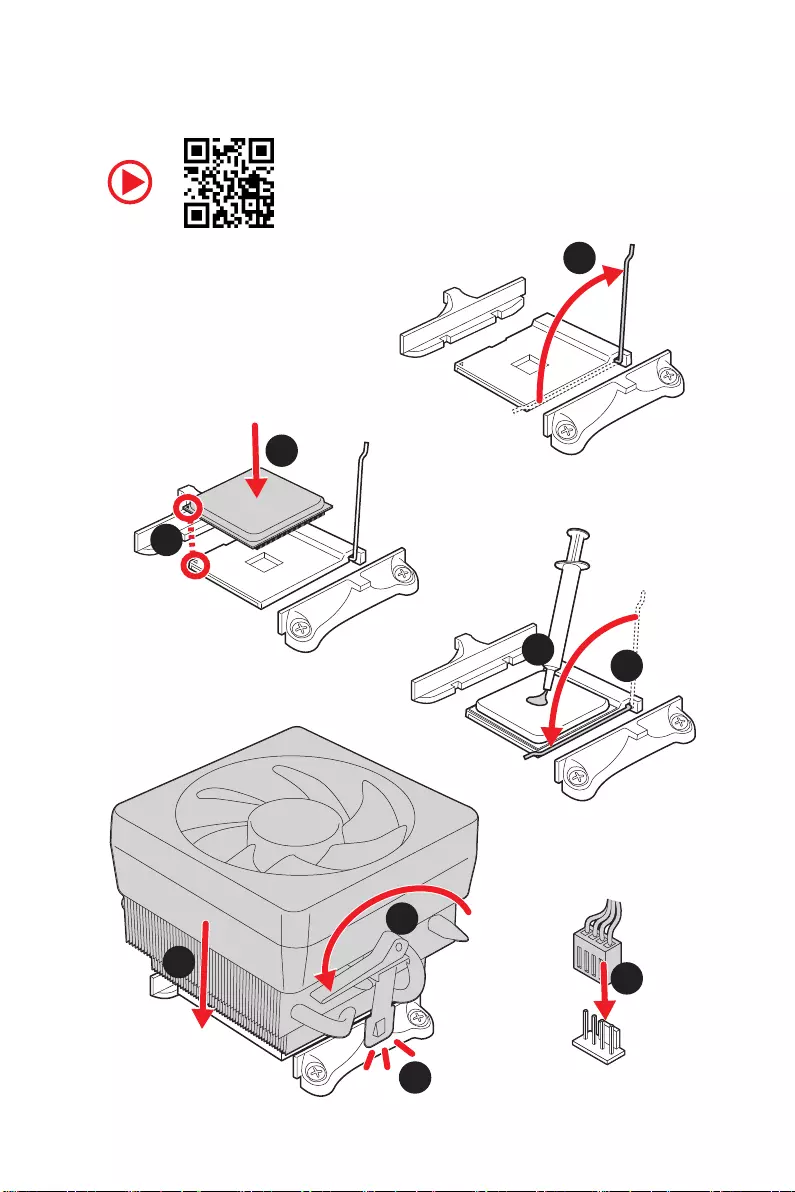
Installing a Processor
1
2
3
6
4
5
7
8
9
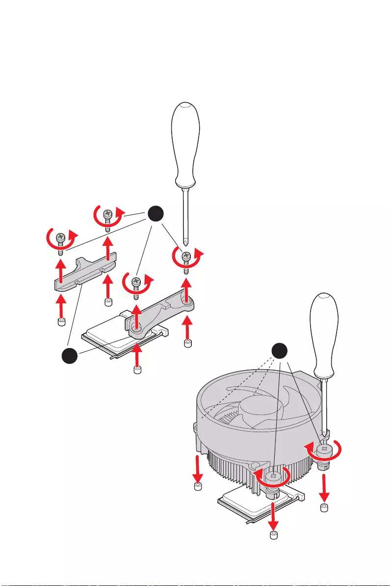
4Quick Start
1
23
⚠
Important
If you are installing the screw-type CPU heatsink, please follow the figure below to
remove the retention module first and then install the heatsink.
5
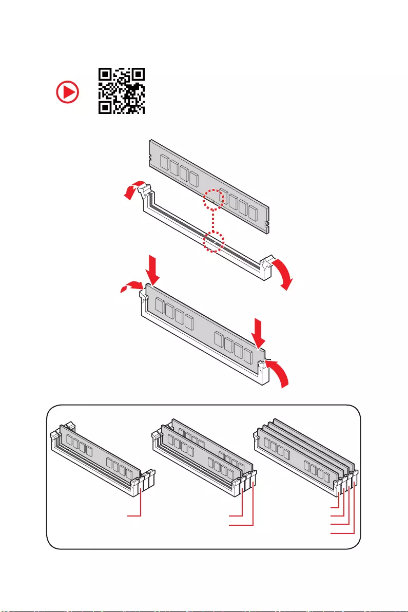
Quick Start
Installing DDR4 memory
DIMMA2 DIMMA2
DIMMB2
DIMMA1
DIMMA2
DIMMB1
DIMMB2
6Quick Start
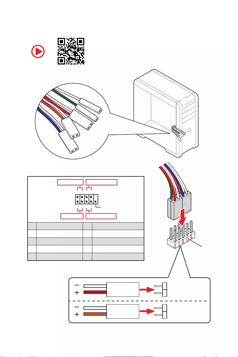
HDD LED
RESET SW
Connecting the Front Panel Header
JFP1
HDD LED HDD LED —
HDD LED +
POWER LED —
POWER LED +
POWER LED
1
2 10
9
+
+
+— ——
—
+
Power LED
HDD LED Reset Switch
Reserved
Power Switch
JFP1
1 HDD LED + 2 Power LED +
3 HDD LED — 4 Power LED —
5 Reset Switch 6 Power Switch
7 Reset Switch 8 Power Switch
9 Reserved 10 No Pin
RESET SW
POWER SW
POWER LED+
POWER LED-
HDD LED
7
Quick Start
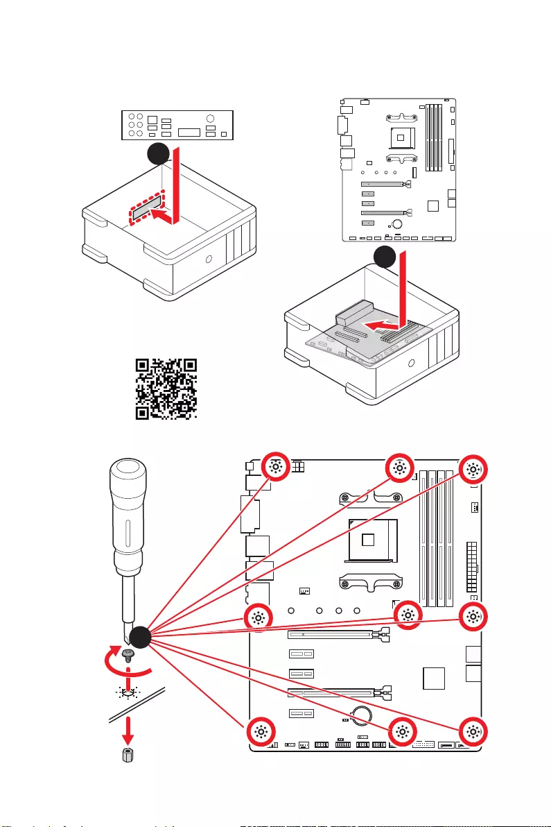
BAT1
Installing the Motherboard
⚽
Torque:
3 kgf·cm*
*3 kgf·cm
= 0.3 N·m
= 2.6 lbf·in
2
1
BAT1
3
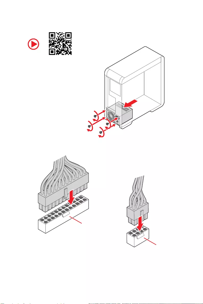
8Quick Start
Connecting the Power Connectors
ATX_PWR1
CPU_PWR1
CPU_PWR2
9
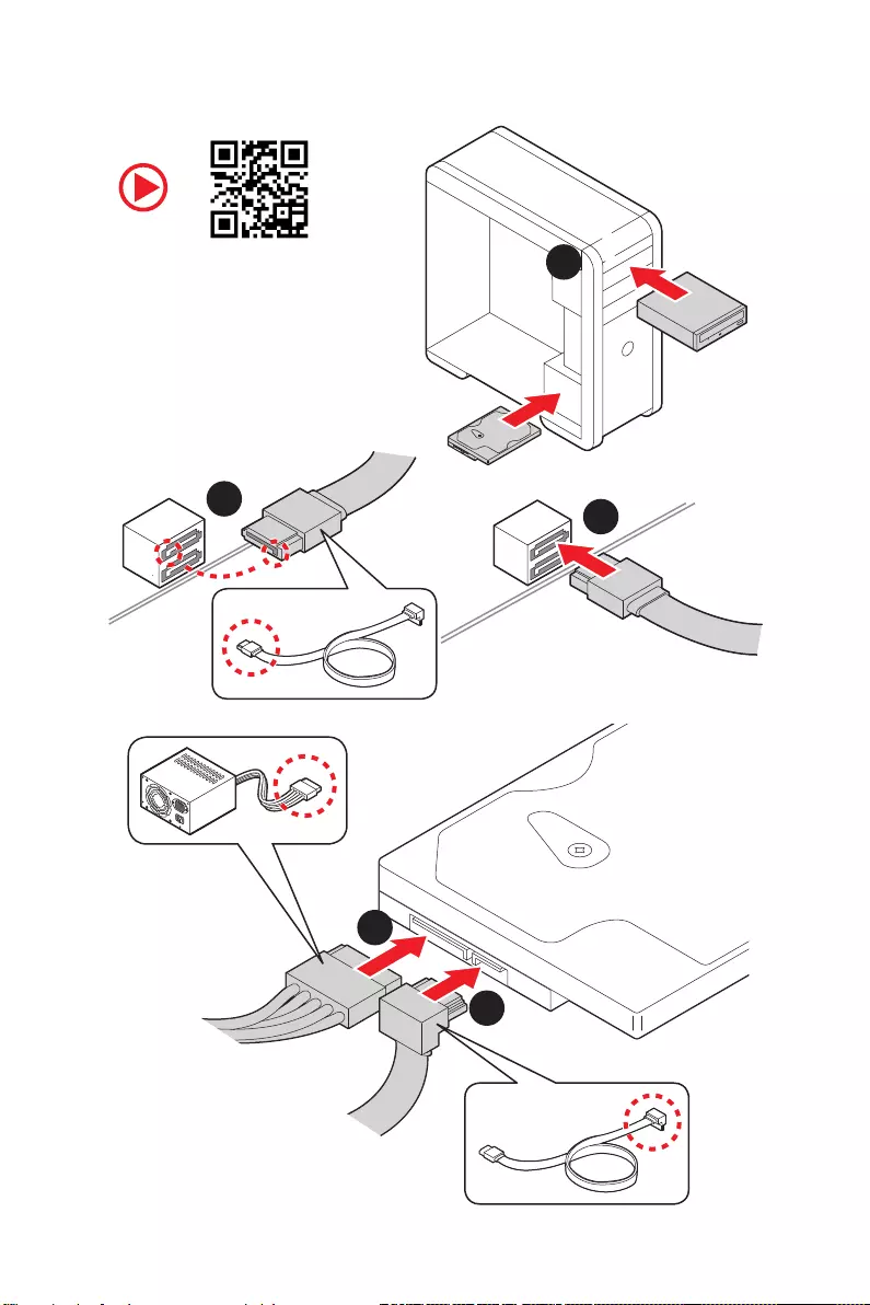
Quick Start
Installing SATA Drives
1
23
4
5
10 Quick Start
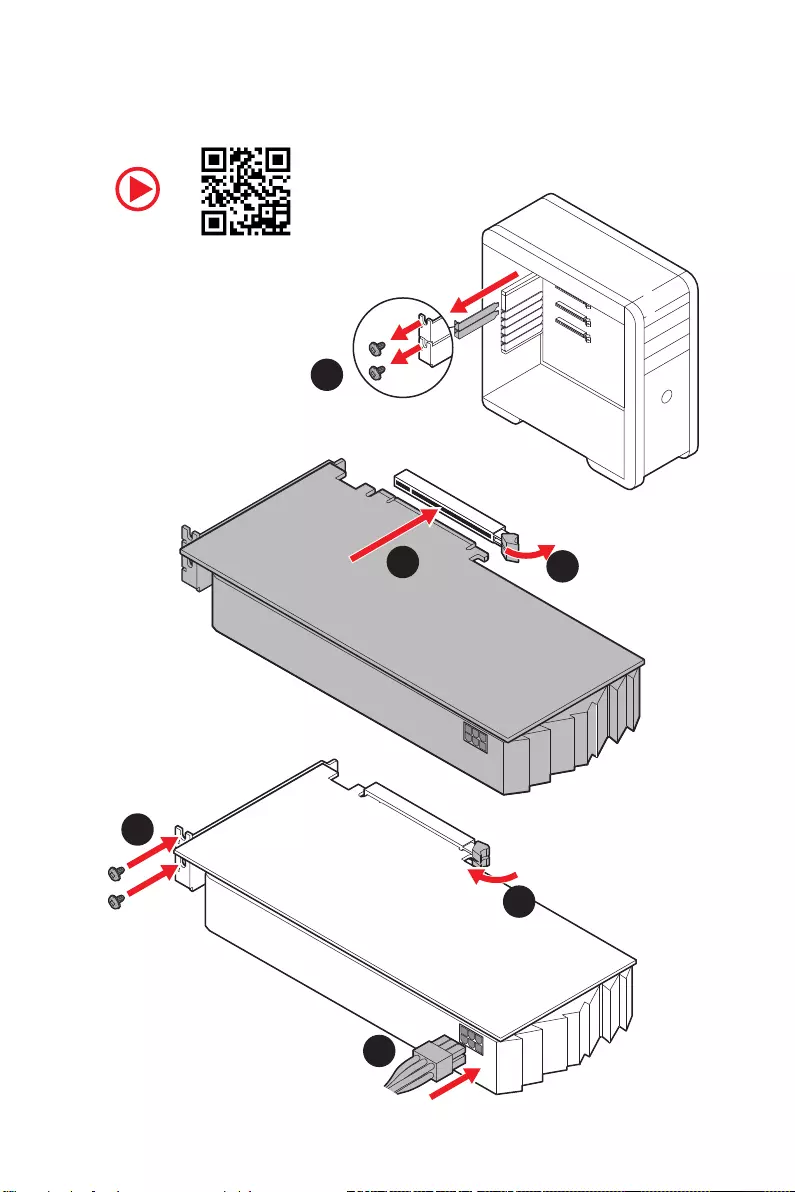
1
Installing a Graphics Card
2
3
4
5
6
11
Quick Start
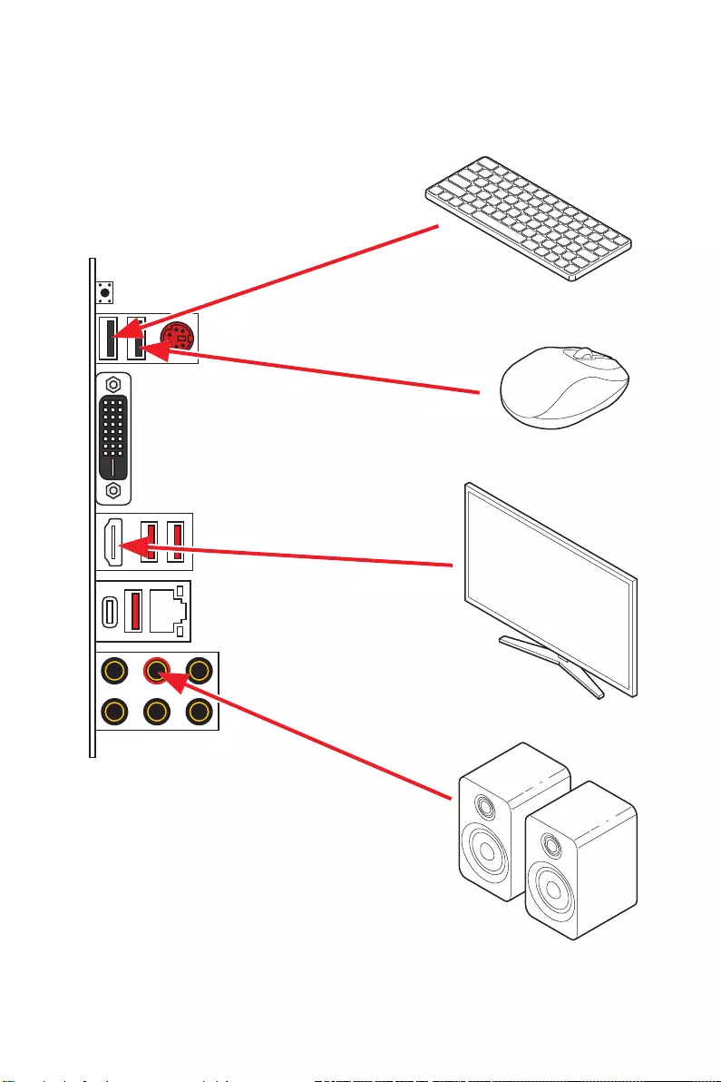
Connecting Peripheral Devices
Processor with Radeon™ Graphics
12 Quick Start
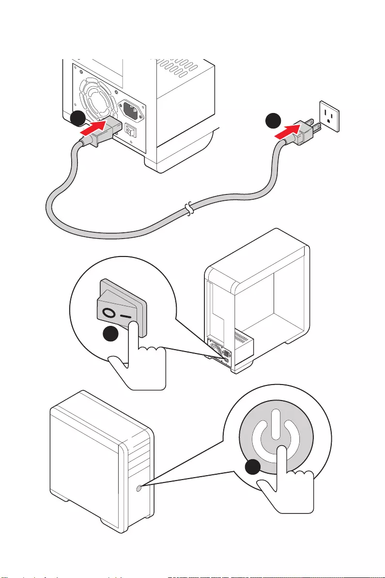
Power On
4
3
12

13
Contents
Contents
Quick Start ………………………………………………………………………………………………. 1
Preparing Tools and Components ……………………………………………………………….. 1
Safety Information …………………………………………………………………………………….. 2
Installing a Processor ………………………………………………………………………………… 3
Installing DDR4 memory ……………………………………………………………………………. 5
Connecting the Front Panel Header …………………………………………………………….. 6
Installing the Motherboard …………………………………………………………………………. 7
Connecting the Power Connectors ………………………………………………………………. 8
Installing SATA Drives………………………………………………………………………………… 9
Installing a Graphics Card ………………………………………………………………………… 10
Connecting Peripheral Devices …………………………………………………………………. 11
Power On………………………………………………………………………………………………… 12
Specifications …………………………………………………………………………………………. 15
Package contents……………………………………………………………………………………. 20
Block Diagram ………………………………………………………………………………………. 21
Rear I/O Panel ………………………………………………………………………………………… 22
LAN Port LED Status Table……………………………………………………………………….. 22
Audio Ports Configuration ………………………………………………………………………… 22
Realtek Audio Console …………………………………………………………………………….. 23
Overview of Components ………………………………………………………………………… 25
Processor Socket …………………………………………………………………………………….. 27
DIMM Slots ……………………………………………………………………………………………… 28
PCI_E1~5: PCIe Expansion Slots ……………………………………………………………….. 29
M2_1: M.2 Slot (Key M) …………………………………………………………………………….. 30
SATA1~6: SATA 6Gb/s Connectors …………………………………………………………….. 30
JFP1, JFP2: Front Panel Connectors …………………………………………………………. 31
JAUD1: Front Audio Connector …………………………………………………………………. 31
CPU_PWR1, ATX_PWR1: Power Connectors ………………………………………………. 32
JUSB1~2: USB 2.0 Connectors ………………………………………………………………….. 33
JUSB3: USB 3.2 Gen 1 Connector ……………………………………………………………… 33
CPU_FAN1, PUMP_FAN1, SYS_FAN1~4: Fan Connectors …………………………….. 34
JCI1: Chassis Intrusion Connector …………………………………………………………….. 35
JCOM1: Serial Port Connector ………………………………………………………………….. 35
JTPM1: TPM Module Connector ………………………………………………………………… 36
JBAT1: Clear CMOS (Reset BIOS) Jumper ………………………………………………….. 36
JRGB1~2: RGB LED connectors ………………………………………………………………… 37
EZ Debug LEDs ……………………………………………………………………………………….. 38

14 Contents
Installing OS, Drivers & Utilities ………………………………………………………………. 39
Installing Windows® 10 …………………………………………………………………………… 39
Installing Drivers …………………………………………………………………………………….. 39
Installing Utilities ……………………………………………………………………………………. 39
UEFI BIOS ………………………………………………………………………………………………. 40
BIOS Setup ……………………………………………………………………………………………… 41
Entering BIOS Setup ………………………………………………………………………………… 41
Resetting BIOS ………………………………………………………………………………………… 42
Updating BIOS …………………………………………………………………………………………. 42
EZ Mode …………………………………………………………………………………………………. 44
Advanced Mode ………………………………………………………………………………………. 47
SETTINGS Menu ……………………………………………………………………………………… 48
OC Menu…………………………………………………………………………………………………. 50
M-FLASH Menu ………………………………………………………………………………………. 52
OC PROFILE Menu …………………………………………………………………………………… 53
HARDWARE MONITOR Menu …………………………………………………………………….. 54
AMD RAID Configuration …………………………………………………………………………. 56
Enabling RAIDXpert2 Configuration Utility …………………………………………………. 56
Initializing Disks ……………………………………………………………………………………… 57
Creating Arrays ……………………………………………………………………………………….. 58
Deleting Arrays ……………………………………………………………………………………….. 59
Installing RAID Driver ………………………………………………………………………………. 60
Troubleshooting …………………………………………………………………………………….. 61

15
Specifications
Specifications
CPU
Supports 1st, 2nd and 3rd Gen AMD Ryzen™/ Ryzen™ with
Radeon™ Vega Graphics and 2nd Gen AMD Ryzen™ with
Radeon™ Graphics/ Athlon™ with Radeon™ Vega Graphics
Desktop Processors for Socket AM4
Chipset AMD® B450 Chipset
Memory
∙4x DDR4 memory slots, support up to 128GB*
▪Supports 1866/ 2133/ 2400/ 2667Mhz (by JEDEC)
▪For AMD Ryzen Gen3 (R5/R7/R9)
▫Supports 2667/ 2800/ 2933/ 3000/ 3066/ 3200/ 3466/
4000/ 4133 MHz (by A-XMP OC MODE)
▪For AMD Other CPU
▫Supports 2667/ 2800/ 2933/ 3000/ 3066/ 3200/ 3466
MHz (by A-XMP OC MODE)
∙ Dual channel memory architecture
∙ Supports non-ECC UDIMM memory
∙ Supports ECC UDIMM memory (non-ECC mode)
*Please refer to www.msi.com for more information on compatible memory.
Expansion Slots
∙1x PCIe 3.0 x16 slot (PCI_E1)
▪supports x16 speed (1st, 2nd and 3rd Gen AMD Ryzen™
processors)
▪supports x8 speed (Ryzen™ with Radeon™ Vega
Graphics and 2nd Gen AMD Ryzen™ with Radeon™
Graphics processors)
▪supports x4 speed (Athlon™ with Radeon™ Vega
Graphics processors)
∙1x PCIe 2.0 x16 slot (PCI_E4, supports x4 mode)*
∙3x PCIe 2.0 x1 slots*
* PCI_E4 will run at x2 speed when installing devices in PCI_E2/ PCI_E3 slot.
Onboard Graphics
∙1x DVI-D port, supports a maximum resolution of
1920×1200 @60Hz*/**
∙1x HDMI™ 2.1 port, supports a maximum resolution of
4096×2160 @60Hz*/**/***
* Maximum shared memory of 16GB
** Only available when using Ryzen™ with Radeon™ Vega Graphics and 2nd Gen
AMD Ryzen™ with Radeon™ Graphics/ Athlon™ with Radeon™ Vega Graphics
processors.
*** Graphics specifications may vary depending on the CPU installed.
Continued on next page

16 Specifications
Continued from previous page
Storage
AMD® CPU
∙2x SATA 6Gb/s ports*
∙1x M.2 slot (Key M)*
▪Supports PCIe 3.0 x4 (1st, 2nd and 3rd Gen AMD
Ryzen™/ Ryzen™ with Radeon™ Vega Graphics and 2nd
Gen AMD Ryzen™ with Radeon™ Graphics) or PCIe 3.0 x2
(Athlon™ with Radeon™ Vega Graphics) and SATA 6Gb/s
▪Supports 2242/ 2260/ 2280/ 22110 storage devices
AMD® B450 Chipset
∙ 4x SATA 6Gb/s ports
* SATA5 and SATA6 ports will be unavailable when installing a M.2 device in M.2
slot.
RAID
AMD® B450 Chipset
∙Supports RAID 0, RAID 1 and RAID 10 for SATA storage
devices
USB
∙AMD® CPU
▪2x USB 3.2 Gen 1 5Gbps Type-A ports on the back
panel
∙AMD® B450 Chipset
▪1x USB 3.2 Gen 2 10Gbps Type-C port on the back
panel
▪1x USB 3.2 Gen 2 10Gbps Type-A port on the back
panel
▪2x USB 3.2 Gen 1 5Gbps ports available through the
internal USB connector
▪6x USB 2.0 ports (2 Type-A ports on the back panel, 4
ports available through the internal USB 2.0 connectors)
LAN ∙1x Realtek® 8111H Gigabit LAN controller
Audio Realtek® ALC892/ALC897 Codec
∙7.1-Channel High Definition Audio
Continued on next page

17
Specifications
Continued from previous page
Back Panel
Connectors
∙1x Flash BIOS Button
∙1x PS/2 keyboard/ mouse combo port
∙2x USB 2.0 Type-A ports
∙1x DVI-D port
∙1x HDMI port
∙2x USB 3.2 Gen 1 5Gbps Type-A ports
∙1x USB 3.2 Gen 2 10Gbps Type-A port
∙1x USB 3.2 Gen 2 10Gbps Type-C port
∙1x LAN(RJ45) port
∙6x audio jacks
Internal Connectors
∙1x 24-pin ATX main power connector
∙1x 8-pin ATX 12V power connector
∙6x SATA 6Gb/s connectors
∙1x USB 3.2 Gen 1 5Gbps connector (support additional 2
USB 3.2 Gen 1 5Gbps ports)
∙2x USB 2.0 connectors (support additional 4 USB 2.0 ports)
∙1x 4-pin CPU fan connector
∙1x 4-pin water pump connector
∙4x 4-pin system fan connectors
∙1x front panel audio connector
∙2x system panel connectors
∙1x serial port connector
∙1x Chassis Intrusion connector
∙1x Clear CMOS jumper
∙2x 5050 RGB LED strip 12V connectors
∙1x TPM module connector
LED Feature ∙4x EZ Debug LED
I/O Controller NUVOTON NCT6797 Controller Chip
Hardware Monitor
∙CPU/System temperature detection
∙CPU/System fan speed detection
∙CPU/System fan speed control
Continued on next page

18 Specifications
Continued from previous page
Form Factor ∙ATX Form Factor
∙12 in. x 9.6 in. (30.5 cm x 24.4 cm)
BIOS Features
∙1x 256 Mb flash
∙UEFI AMI BIOS
∙ACPI 6.1, SM BIOS 2.8
∙Multi-language
Software
∙Drivers
∙DRAGON CENTER
∙MSI App Player(BlueStacks)
∙Open Broadcaster Software (OBS)
∙CPU-Z MSI GAMING
∙Google Chrome™, Google Toolbar, Google Drive
∙Norton™ Internet Security Solution
Dragon Center
Features
∙Gaming Mode
∙Gaming Hotkey
∙Mystic Light
∙User Scenario
∙Hardware Monitor
∙True Color
∙Live Update
∙Speed Up
∙Smart Tool
∙Super Charger
Special Features
∙Audio
▪Audio Boost
∙Network
▪Realtek LAN
∙Storage
▪Turbo M.2
Continued on next page

19
Specifications
Continued from previous page
Special Features
∙Cooling
▪Extended heatsink
▪Pump Fan
▪GAMING Fan Control
∙LED
▪Mystic Light
▪Mystic Light Extension (RGB)
▪Mystic light SYNC
▪EZ DEBUG LED
∙Protection
▪PCIe Steel Armor
▪PCIe Steel Slot
∙Performance
▪Multi GPU-CrossFire Technology
▪DDR4 Boost
▪CORE Boost
▪GAME Boost
▪USB with type A+C
▪AMD Turbo USB 3.2 Gen 2
∙VR
▪VR Ready
∙Gamer Experience
▪GAMING HOTKEY
▪GAMING MOUSE Control
∙BIOS
▪Click BIOS 5
▪Flash BIOS Button
▪StoreMI (SW feature)
▪AMD FreeSync™ Ready
▪AMD Precision Boost OverDrive™
∙Certification
▪GAMING Certified
20 Package contents
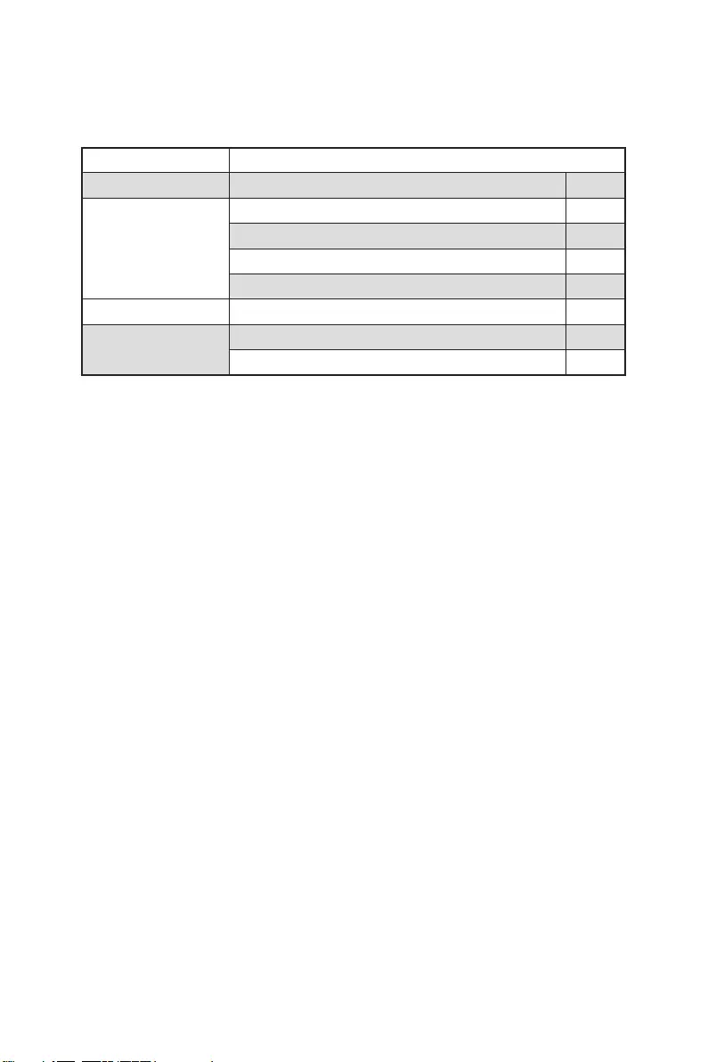
Package contents
Please check the contents of your motherboard package. It should contain:
Motherboard B450 TOMAHAWK MAX II
Cable SATA 6G cables (2 cables/pack) 1
Accessories
M.2 screws (3 pcs./pack) 1
Case badge 1
I/O Shielding 1
Product registration card 1
Application Driver DVD 1
Documentation User manual 1
Quick installation guide 1
⚠
Important
If any of the above items are damaged or missing, please contact your retailer.
21
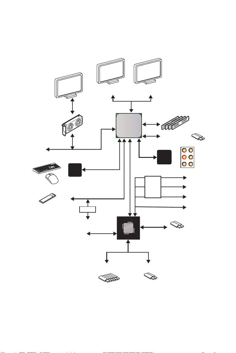
Block Diagram
Block Diagram
2 x USB 3.2 Gen 2
2 Channel DDR4 Memory
2 x USB 3.2 Gen 1
1 x M.2
6 x USB 2.0
PCI Express Bus
PS/2 Mouse / Keyboard
Audio Jacks
CHIPSET
NV6797
Super I/O
Realtek
ALC892/
ALC897
PCI Express Bus
HDMI DVI-D
SwitchSwitch
PCIe x1
2x SATA 6Gb/s
4x SATA 6Gb/s
PCIe x1
PCIe x1
PCIe x4
2x USB 3.2 Gen 1
Switch
Processor
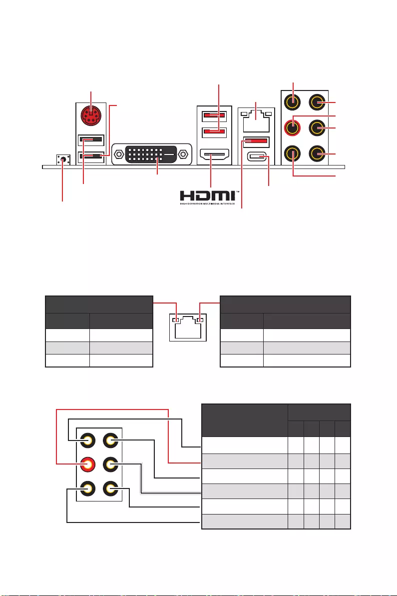
22 Rear I/O Panel
Link/ Activity LED
Status Description
Off No link
Yellow Linked
Blinking Data activity
Speed LED
Status Description
Off 10 Mbps connection
Green 100 Mbps connection
Orange 1 Gbps connection
LAN Port LED Status Table
Audio Ports Configuration
Audio Ports Channel
2468
Line-In
Line-Out/ Front Speaker Out
Rear Speaker Out
Center/ Subwoofer Out
Side Speaker Out
Mic In
Blank: empty)
Rear I/O Panel
∙Flash BIOS Port/ Button — Please refer to page 43 for Updating BIOS with Flash BIOS
Button.
Line-In
USB 3.2 Gen 2
(10Gbps) Type-C
PS/2 Combo Port
LAN Port
USB 2.0 Type-A DVI-D Port
USB 3.2 Gen 1
(5Gbps) Type-A
USB 3.2 Gen 2
(10Gbps) Type-A
Flash BIOS Button
Flash BIOS Port
Mic-In
Line-Out
RS-Out
CS-Out
SS-Out
23
Rear I/O Panel
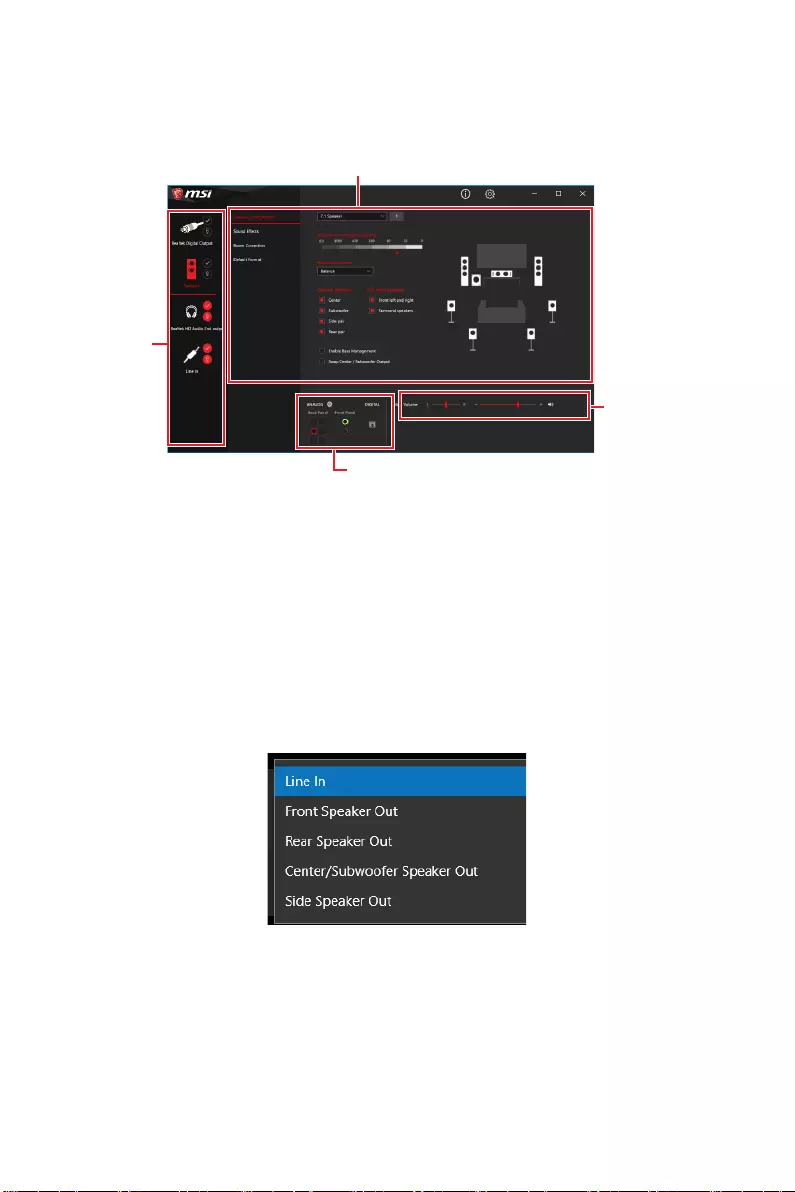
Realtek Audio Console
After Realtek Audio Console is installed. You can use it to change sound settings to get
better sound experience.
∙Device Selection — allows you to select a audio output source to change the related
options. The check sign indicates the devices as default.
∙Application Enhancement — the array of options will provide you a complete
guidance of anticipated sound effect for both output and input device.
∙Main Volume — controls the volume or balance the right/left side of the speakers
that you plugged in front or rear panel by adjust the bar.
∙Jack Status — depicts all render and capture devices currently connected with your
computer.
Auto popup dialog
When you plug into a device at an audio jack, a dialogue window will pop up asking you
which device is current connected.
Each jack corresponds to its default setting as shown on the next page.
Jack Status
Device
Selection
Main Volume
Application Enhancement
⚠
Important
The pictures above for reference only and may vary from the product you purchased.
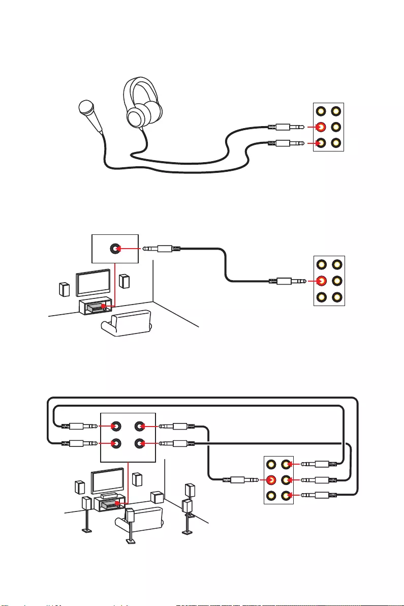
24 Rear I/O Panel
Audio jacks to headphone and microphone diagram
Audio jacks to stereo speakers diagram
Audio jacks to 7.1-channel speakers diagram
AUDIO INPUT
Rear Front
Side Center/
Subwoofer
AUDIO INPUT
25
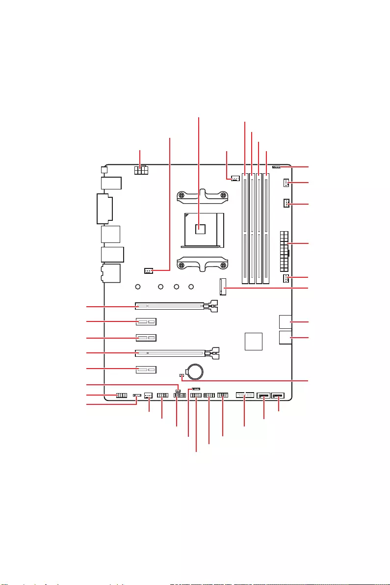
Overview of Components
BAT1
Overview of Components
JFP2
JFP1
CPU_FAN1
SYS_FAN1
PUMP_FAN1
JRGB2
PCI_E1
PCI_E2
PCI_E3
PCI_E4
PCI_E5
JBAT1
JAUD1
JTPM1
Processor Socket
CPU_PWR1
DIMMA1
SYS_FAN4
M2_1
DIMMA2
DIMMB1
DIMMB2
JUSB3
SATA2
JUSB2
JUSB1
SATA1
JRGB1
SYS_FAN2
JCOM1
ATX_PWR1
SYS_FAN3
JCI1
26 Overview of Components
Component Contents
Port Name Port Type Page
CPU_FAN1, PUMP_FAN1, SYS_FAN1~4 Fan Connectors 34
CPU_PWR1, ATX_PWR1 Power Connectors 32
DIMMA1, DIMMA2, DIMMB1, DIMMB2 DIMM Slots 28
JAUD1 Front Audio Connector 31
JBAT1 Clear CMOS (Reset BIOS)
Jumper 36
JCI1 Chassis Intrusion Connector 35
JCOM1 Serial Port Connector 35
JFP1, JFP2 Front Panel Connectors 31
JRGB1~2 RGB LED connectors 37
JTPM1 TPM Module Connector 36
JUSB1~2 USB 2.0 Connectors 33
JUSB3 USB 3.2 Gen 1 Connector 33
M2_1 M.2 Slot (Key M) 30
PCI_E1~5 PCIe Expansion Slots 29
Processor Socket AM4 socket 27
SATA1~6 SATA 6Gb/s Connectors 30
27
Overview of Components
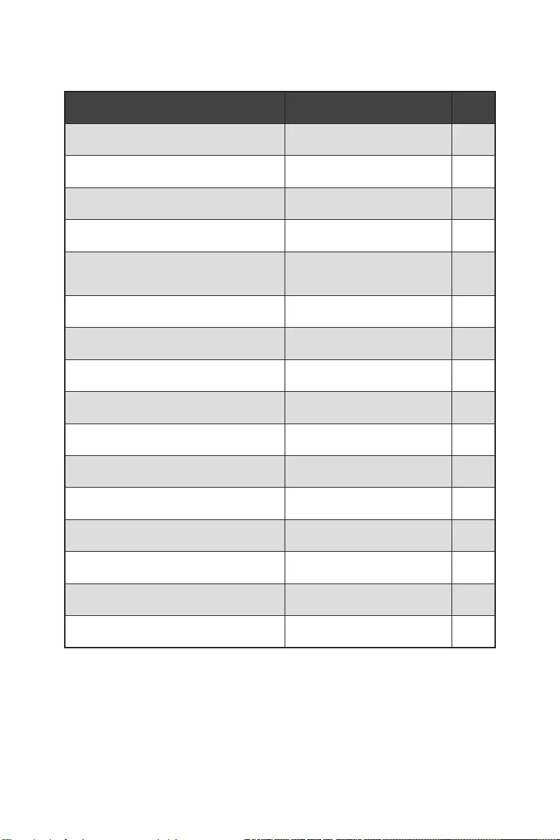
Processor Socket
⚠
Important
∙
When changing the processor, the system configuration could be cleared and reset
BIOS to default values, due to the AM4 processor’s architecture.
∙
Always unplug the power cord from the power outlet before installing or removing
the CPU.
∙
When installing a CPU, always remember to install a CPU heatsink. A CPU heatsink
is necessary to prevent overheating and maintain system stability.
∙
Confirm that the CPU heatsink has formed a tight seal with the CPU before booting
your system.
∙
Overheating can seriously damage the CPU and motherboard. Always make sure
the cooling fans work properly to protect the CPU from overheating. Be sure to apply
an even layer of thermal paste (or thermal tape) between the CPU and the heatsink to
enhance heat dissipation.
∙
If you purchased a separate CPU and heatsink/ cooler, Please refer to the
documentation in the heatsink/ cooler package for more details about installation.
∙
This motherboard is designed to support overclocking. Before attempting to
overclock, please make sure that all other system components can tolerate
overclocking. Any attempt to operate beyond product specifications is not
recommended. MSI
®
does not guarantee the damages or risks caused by inadequate
operation beyond product specifications.
BAT1
Introduction to the AM4 CPU
The surface of the AM4 CPU has a
yellow triangle to assist in correctly
lining up the CPU for motherboard
placement. The yellow triangle is
the Pin 1 indicator.
53.4 mm
Distance from the center of the
CPU to the nearest DIMM slot.
28 Overview of Components
BAT1
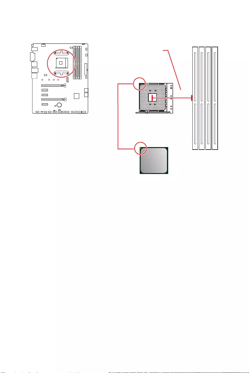
DIMM Slots
DIMMA1 DIMMB1
Channel A Channel B
DIMMA2 DIMMB2
Memory module installation recommendation
⚠
Important
∙
Always insert memory modules in the DIMMA2 slot first.
∙
Due to chipset resource usage, the available capacity of memory will be a little less
than the amount of installed.
∙
Based on processor specification, the Memory DIMM voltage below 1.35V is
suggested to protect the processor.
∙
Some memory modules may operate at a lower frequency than the marked value
when overclocking due to the memory frequency operates dependent on its Serial
Presence Detect (SPD). Go to BIOS and find the DRAM Frequency to set the memory
frequency if you want to operate the memory at the marked or at a higher frequency.
∙
It is recommended to use a more efficient memory cooling system for full DIMMs
installation or overclocking.
∙
The stability and compatibility of installed memory module depend on installed CPU
and devices when overclocking.
∙
Due to AM4 processor/memory controller official specification limitation, the
frequency of memory modules may operate lower than the marked value under
the default state. Please refer www.msi.com for more information on compatible
memory.
DIMMB2 DIMMB2
DIMMB1
DIMMA2 DIMMA2 DIMMA2
DIMMA1
29
Overview of Components
BAT1
PCI_E1~5: PCIe Expansion Slots
PCI_E1: PCIe 3.0 x16*/ x8**/ x4***
PCI_E2: PCIe 2.0 x1
PCI_E3: PCIe 2.0 x1
PCI_E4: PCIe 2.0 x4
PCI_E5: PCIe 2.0 x1
⚠
Important
∙
If you install a large and heavy graphics card, you need to use a tool such as MSI
Gaming Series Graphics Card Bolster to support its weight to prevent deformation of
the slot.
∙
For a single PCIe x16 expansion card installation with optimum performance, using
the PCI_E1 slot is recommended.
∙
When adding or removing expansion cards, always turn off the power supply and
unplug the power supply power cable from the power outlet. Read the expansion
card’s documentation to check for any necessary additional hardware or software
changes.
∙
PCI_E4 will run x2 speed when installing devices in PCI_E2/ PCI_E3 slot.
* For 1st, 2nd and 3rd Gen AMD Ryzen™ processors
** For Ryzen™ with Radeon™ Vega Graphics and 2nd Gen AMD Ryzen™ with Radeon™
Graphics processors
*** For Athlon™ with Radeon Vega Graphics processors
PCIe bandwidth of Multiple graphics cards
Slot Single 2-Way
PCI_E1 (CPU)
@3.0 x16*
or
@3.0 x8**
or
@3.0 x4***
@3.0 x16*
or
@3.0 x8**
or
@3.0 x4***
PCI_E2 (PCH) 2.0 x1 2.0 x1 Empty — —
PCI_E3 (PCH) 2.0 x1 Empty 2.0 x1 — —
PCI_E4 (PCH) 2.0 x2 2.0 x2 2.0 x2 2.0 x4 @2.0 x4
PCI_E5 (PCH) 2.0 x1 2.0 x1
processors,
**: for Ryzen™ with Radeon™ Vega Graphics and 2nd Gen AMD Ryzen™ with Radeon™
Graphics processors,***: for Athlon™ with Radeon Vega Graphics processor)
30 Overview of Components
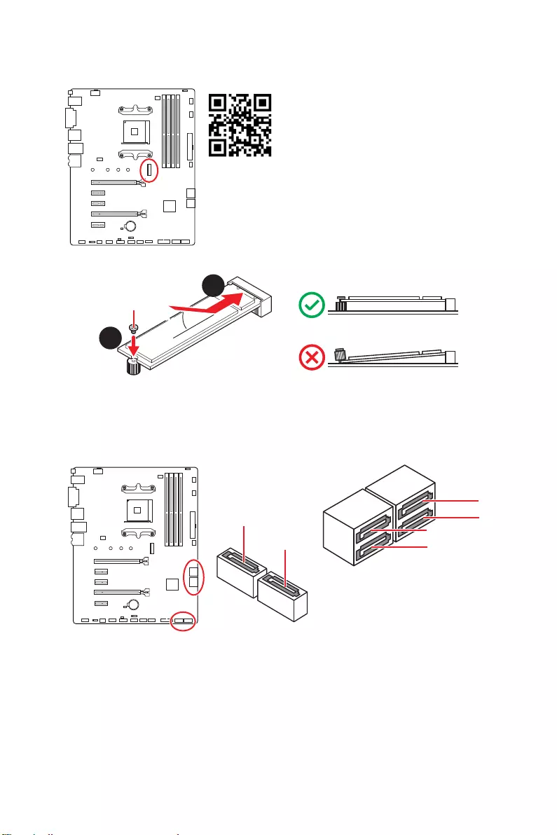
SATA1~6: SATA 6Gb/s Connectors
These connectors are SATA 6Gb/s interface ports. Each connector can connect to one
SATA device.
BAT1
SATA2
SATA1
⚠
Important
∙
Please do not fold the SATA cable at a 90-degree angle. Data loss may result during
transmission otherwise.
∙
SATA cables have identical plugs on either sides of the cable. However, it is
recommended that the flat connector be connected to the motherboard for space
saving purposes.
∙
SATA5 and SATA6 ports will be unavailable when installing a M.2 device in M.2 slot.
SATA5
SATA6
SATA3
SATA4
BAT1
M2_1: M.2 Slot (Key M)
⚽
Video Demonstration
Watch the video to learn how to Install
M.2 module.
M2_1 slot installation
1. Insert your M.2 SSD into the M.2 slot at a 30-degree
angle.
2. Secure the M.2 SSD in place with the M.2 screw.
30º30º
3
4
M.2 screw
31
Overview of Components
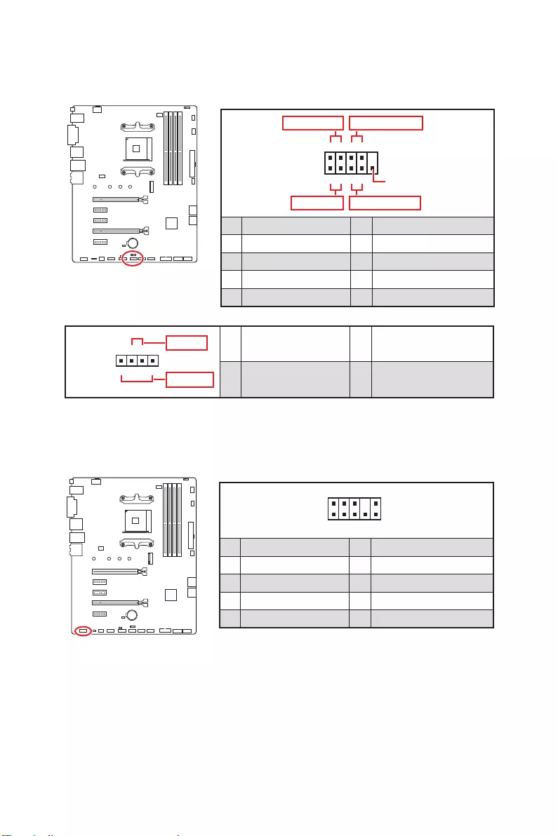
JFP1, JFP2: Front Panel Connectors
These connectors connect to the switches and LEDs on the front panel.
1
JFP2
+
+—
—
Speaker
Buzzer 1 Speaker — 2 Buzzer +
3 Buzzer — 4 Speaker +
BAT1
1
2 10
9
+
+
+— ——
—
+
Power LED
HDD LED Reset Switch
Reserved
Power Switch
JFP1
1 HDD LED + 2 Power LED +
3 HDD LED — 4 Power LED —
5 Reset Switch 6 Power Switch
7 Reset Switch 8 Power Switch
9 Reserved 10 No Pin
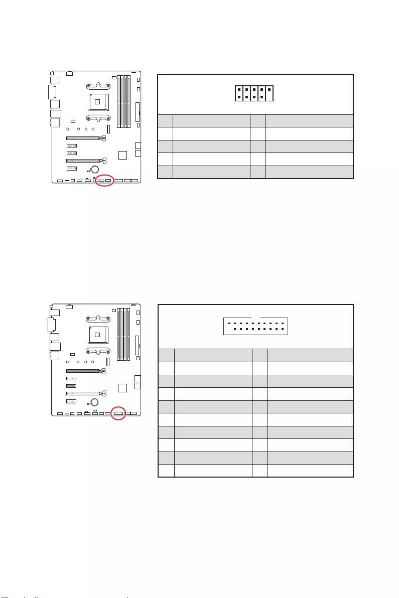
BAT1
JAUD1: Front Audio Connector
This connector allows you to connect audio jacks on the front panel.
1
2 10
9
1 MIC L 2 Ground
3 MIC R 4 NC
5 Head Phone R 6 MIC Detection
7 SENSE_SEND 8 No Pin
9 Head Phone L 10 Head Phone Detection
32 Overview of Components
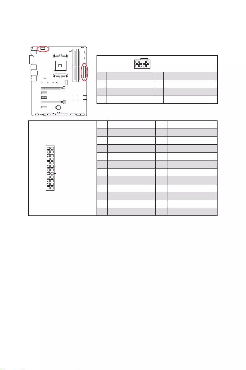
BAT1
24
131
12
ATX_PWR1
1 +3.3V 13 +3.3V
2 +3.3V 14 -12V
3 Ground 15 Ground
4 +5V 16 PS-ON#
5 Ground 17 Ground
6 +5V 18 Ground
7 Ground 19 Ground
8 PWR OK 20 Res
9 5VSB 21 +5V
10 +12V 22 +5V
11 +12V 23 +5V
12 +3.3V 24 Ground
5
4 1
8CPU_PWR1
1 Ground 5 +12V
2 Ground 6 +12V
3 Ground 7 +12V
4 Ground 8 +12V
⚠
Important
Make sure that all the power cables are securely connected to a proper ATX power
supply to ensure stable operation of the motherboard.
CPU_PWR1, ATX_PWR1: Power Connectors
These connectors allow you to connect an ATX power supply.
33
Overview of Components
JUSB1~2: USB 2.0 Connectors
These connectors allow you to connect USB 2.0 ports on the front panel.
1
2 10
9
1 VCC 2 VCC
3 USB0- 4 USB1-
5 USB0+ 6 USB1+
7 Ground 8 Ground
9 No Pin 10 NC
⚠
Important
∙
Note that the VCC and Ground pins must be connected correctly to avoid possible
damage.
∙
In order to recharge your iPad, iPhone and iPod through USB ports, please install
MSI® SUPER CHARGER utility.
BAT1
JUSB3: USB 3.2 Gen 1 Connector
This connector allows you to connect USB 3.2 Gen 1 ports on the front panel.
⚠
Important
Note that the Power and Ground pins must be connected correctly to avoid possible
damage.
BAT1
110
11
20
1 Power 11 USB2.0+
2 USB3_RX_DN 12 USB2.0-
3 USB3_RX_DP 13 Ground
4 Ground 14 USB3_TX_C_DP
5 USB3_TX_C_DN 15 USB3_TX_C_DN
6 USB3_TX_C_DP 16 Ground
7 Ground 17 USB3_RX_DP
8 USB2.0- 18 USB3_RX_DN
9 USB2.0+ 19 Power
10 NC 20 No Pin
34 Overview of Components
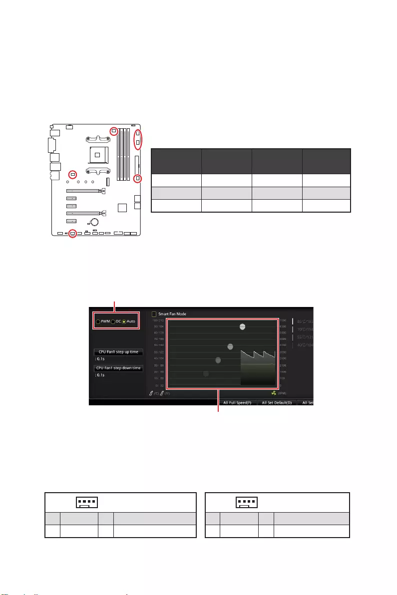
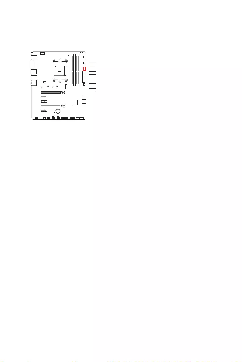
BAT1
CPU_FAN1, PUMP_FAN1, SYS_FAN1~4: Fan Connectors
Fan connectors can be classified as PWM (Pulse Width Modulation) Mode or DC Mode.
PWM Mode fan connectors provide constant 12V output and adjust fan speed with
speed control signal. DC Mode fan connectors control fan speed by changing voltage.
The auto mode fan connectors can automatically detect PWM and DC mode. However,
you can follow the instruction below to adjust the fan connector to PWM or DC Mode
manually.
Connector Default fan
mode Max.
current Max.
power
CPU_FAN1 Auto mode 1A 12W
PUMP_FAN1 PWM mode 2A 24W
SYS_FAN1~6 DC mode 1A 12W
Switching fan mode and adjusting fan speed
You can switch between PWM mode and DC mode and adjust fan speed in BIOS >
HARDWARE MONITOR.
Select PWM mode or DC mode
⚠
Important
Make sure fans are working properly after switching the PWM/ DC mode.
There are gradient points of the fan speed that allow you to adjust
fan speed in relation to CPU temperature.
Pin definition of fan connectors
1 PWM Mode pin definition
1 Ground 2 +12V
3 Sense 4 Speed Control Signal
1 DC Mode pin definition
1 Ground 2 Voltage Control
3 Sense 4 NC
35
Overview of Components
JCI1: Chassis Intrusion Connector
This connector allows you to connect the chassis intrusion switch cable.
BAT1
Normal
(default) Trigger the chassis
intrusion event
Using chassis intrusion detector
1. Connect the JCI1 connector to the chassis intrusion switch/ sensor on the chassis.
2. Close the chassis cover.
3. Go to BIOS > SETTINGS > Security > Chassis Intrusion Configuration.
4. Set Chassis Intrusion to Enabled.
5. Press F10 to save and exit and then press the Enter key to select Yes.
6. Once the chassis cover is opened again, a warning message will be displayed on
screen when the computer is turned on.
Resetting the chassis intrusion warning
1. Go to BIOS > SETTINGS > Security > Chassis Intrusion Configuration.
2. Set Chassis Intrusion to Reset.
3. Press F10 to save and exit and then press the Enter key to select Yes.
BAT1
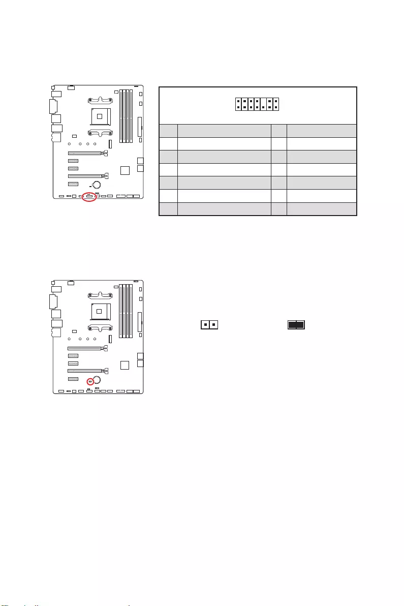
1
2 10
9
1 DCD 2 SIN
3 SOUT 4 DTR
5 Ground 6 DSR
7 RTS 8 CTS
9 RI 10 No Pin
JCOM1: Serial Port Connector
This connector allows you to connect the optional serial port with bracket.
36 Overview of Components
JBAT1: Clear CMOS (Reset BIOS) Jumper
There is CMOS memory onboard that is external powered from a battery located on
the motherboard to save system configuration data. If you want to clear the system
configuration, set the jumper to clear the CMOS memory.
Keep Data
(default) Clear CMOS/
Reset BIOS
BAT1
Resetting BIOS to default values
1. Power off the computer and unplug the power cord.
2. Use a jumper cap to short JBAT1 for about 5-10 seconds.
3. Remove the jumper cap from JBAT1.
4. Plug the power cord and Power on the computer.
1
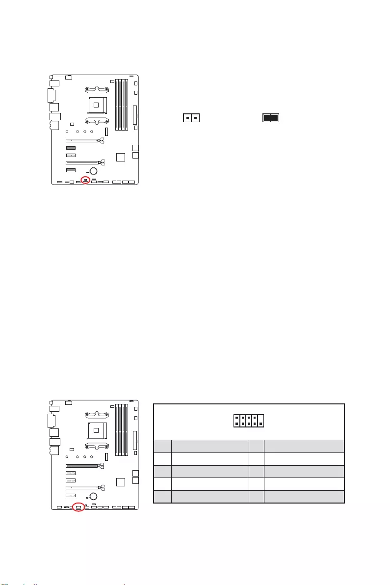
2 14
13
1 LPC Clock 2 3V Standby power
3 LPC Reset 4 3.3V Power
5 LPC address & data pin0 6 Serial IRQ
7 LPC address & data pin1 8 5V Power
9 LPC address & data pin2 10 No Pin
11 LPC address & data pin3 12 Ground
13 LPC Frame 14 Ground
JTPM1: TPM Module Connector
This connector is for TPM (Trusted Platform Module). Please refer to the TPM security
platform manual for more details and usages.
BAT1
37
Overview of Components
BAT1
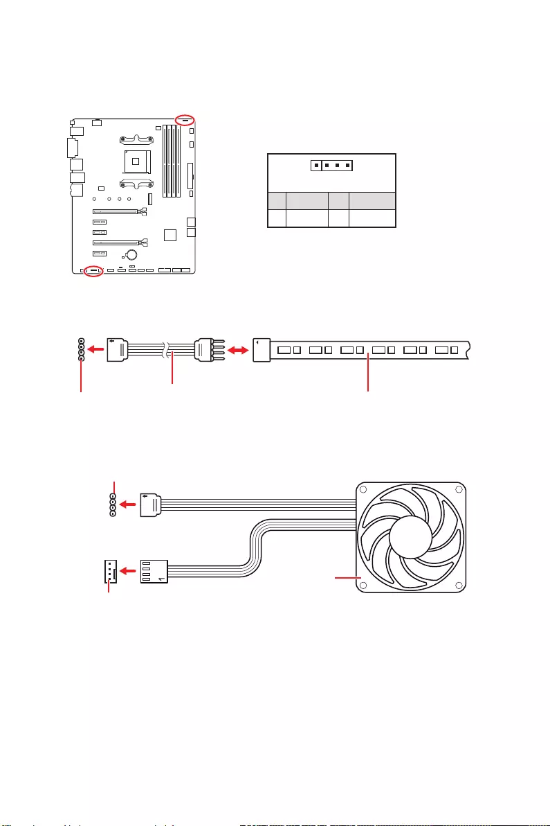
JRGB1~2: RGB LED connectors
The JRGB1/2 connectors allow you to connect the 5050 RGB LED strips 12V.
JRGB1
1
1 +12V 2 G
3 R 4 B
JRGB2
⚠
Important
∙
The JRGB connector supports up to 2 meters continuous 5050 RGB LED strips
(12V/G/R/B) with the maximum power rating of 3A (12V).
∙
Always turn off the power supply and unplug the power cord from the power outlet
before installing or removing the RGB LED strip.
∙
Please use MSI’s software to control the extended LED strip.
1
GRB
JRGB
connector
RGB extension
cable 5050 RGB LED strips 12V
RGB LED Strip Connection
1
1
GRB
JRGB connector
System Fan connector
RGB LED Fan Connection
RGB LED Fan
38 Overview of Components
BAT1
EZ Debug LEDs
These LEDs indicate the status of key components during booting process. When an
error is occurred, the corresponding LED stays lit until the problem is solved.
CPU — indicates CPU is not detected or fail.
DRAM — indicates DRAM is not detected or fail.
VGA — indicates GPU is not detected or fail.
BOOT — indicates the booting device is not detected
or fail.

39
Installing OS, Drivers & Utilities
Installing OS, Drivers & Utilities
Please download and update the latest utilities and drivers at www.msi.com
Installing Windows® 10
1. Power on the computer.
2. Insert the Windows® 10 installation disc/USB into your computer.
3. Press the Restart button on the computer case.
4. Press F11 key during the computer POST (Power-On Self Test) to get into Boot
Menu.
5. Select the Windows® 10 installation disc/USB from the Boot Menu.
6. Press any key when screen shows Press any key to boot from CD or DVD
message.
7. Follow the instructions on the screen to install Windows® 10.
Installing Drivers
1. Start up your computer in Windows® 10.
2. Insert MSI® Drive Disc into your optical drive.
3. Click the Select to choose what happens with this disc pop-up notification, then
select Run DVDSetup.exe to open the installer. If you turn off the AutoPlay feature
from the Windows Control Panel, you can still manually execute the DVDSetup.exe
from the root path of the MSI Drive Disc.
4. The installer will find and list all necessary drivers in the Drivers/Software tab.
5. Click the Install button in the lower-right corner of the window.
6. The drivers installation will then be in progress, after it has finished it will prompt
you to restart.
7. Click OK button to finish.
8. Restart your computer.
Installing Utilities
Before you install utilities, you must complete drivers installation.
1. Open the installer as described above.
2. Click the Utilities tab.
3. Select the utilities you want to install.
4. Click the Install button in the lower-right corner of the window.
5. The utilities installation will then be in progress, after it has finished it will prompt
you to restart.
6. Click OK button to finish.
7. Restart your computer.

40 UEFI BIOS
UEFI BIOS
MSI UEFI BIOS is compatible with UEFI (Unified Extensible Firmware Interface)
architecture. UEFI has many new functions and advantages that traditional BIOS
cannot achieve, and it will completely replace BIOS in the future. The MSI UEFI
BIOS uses UEFI as the default boot mode to take full advantage of the new chipset’s
capabilities. However, it still has a CSM (Compatibility Support Module) mode to be
compatible with older devices. That allows you to replace legacy devices with UEFI
compatible devices during the transition.
⚠
Important
The term BIOS in this user guide refers to UEFI BIOS unless otherwise noted.
UEFI advantages
∙Fast booting — UEFI can directly boot the operating system and save the BIOS self-
test process. And also eliminates the time to switch to CSM mode during POST.
∙Supports for hard drive partitions larger than 2 TB.
∙Supports more than 4 primary partitions with a GUID Partition Table (GPT).
∙Supports unlimited number of partitions.
∙Supports full capabilities of new devices — new devices may not provide backward
compatibility.
∙Supports secure startup — UEFI can check the validity of the operating system to
ensure that no malware tampers with the startup process.
Incompatible UEFI cases
∙32-bit Windows operating system — this motherboard supports only Windows 10
64-bit operating system.
∙Older graphics card — the system will detect your graphics card. When display a
warning message There is no GOP (Graphics Output protocol) support detected in
this graphics card.
⚠
Important
We recommend that you to use a GOP/ UEFI compatible graphics card.
How to check the BIOS mode?
After entering the BIOS, find the BIOS Mode at the top of the screen.
CPU Temperature:
Motherboard Temperature:
VCore:
DDR Voltage:
BIOS Mode: CSM/UEFI
CPU Temperature:
Motherboard Temperature:
VCore:
DDR Voltage:
BIOS Mode: CSM/UEFI
UEFI boot mode CSM boot mode

41
UEFI BIOS
BIOS Setup
The default settings offer the optimal performance for system stability in normal
conditions. You should always keep the default settings to avoid possible system
damage or failure booting unless you are familiar with BIOS.
⚠
Important
∙
BIOS items are continuously update for better system performance. Therefore, the
description may be slightly different from the latest BIOS and should be for reference
only. You could also refer to the HELP information panel for BIOS item description.
∙
The pictures in this chapter are for reference only and may vary from the product
you purchased.
∙
The BIOS items will vary with the processor.
Entering BIOS Setup
Press Delete key, when the Press DEL key to enter Setup Menu, F11 to enter Boot
Menu message appears on the screen during the boot process.
Function key
F1: General Help list
F2: Add/ Remove a favorite item
F3: Enter Favorites menu
F4: Enter CPU Specifications menu
F5: Enter Memory-Z menu
F6: Load optimized defaults
F7: Switch between Advanced mode and EZ mode
F8: Load Overclocking Profile
F9: Save Overclocking Profile
F10: Save Change and Reset*
F12: Take a screenshot and save it to USB flash drive (FAT/ FAT32 format only).
Ctrl+F: Enter Search page
* When you press F10, a confirmation window appears and it provides the modification
information. Select between Yes or No to confirm your choice.
42 UEFI BIOS
Resetting BIOS
You might need to restore the default BIOS setting to solve certain problems. There
are several ways to reset BIOS:
∙Go to BIOS and press F6 to load optimized defaults.
∙Short the Clear CMOS jumper on the motherboard.
⚠
Important
Be sure the computer is off before clearing CMOS data. Please refer to the Clear
CMOS jumper section for resetting BIOS.
Updating BIOS
Updating BIOS with M-FLASH
Before updating:
Please download the latest BIOS file that matches your motherboard model from MSI
website. And then save the BIOS file into the USB flash drive.
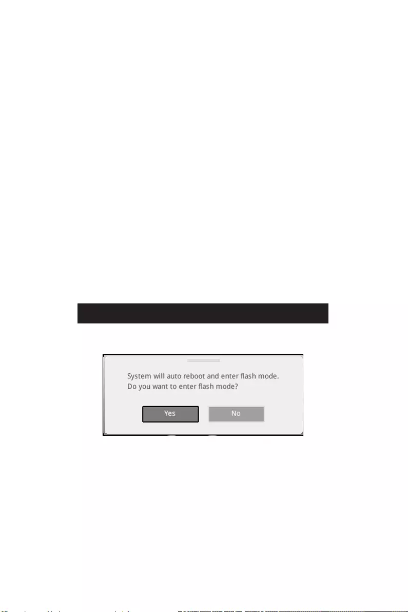
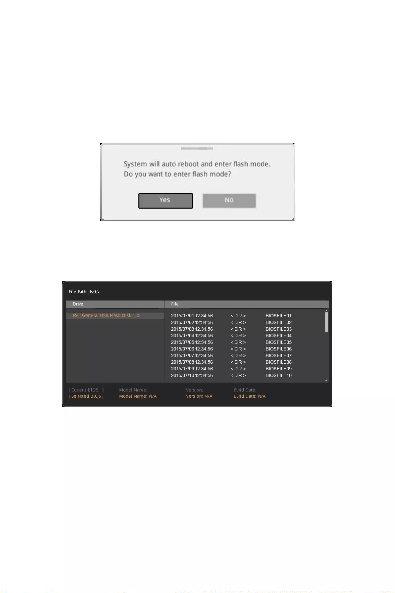
Updating BIOS:
1. Insert the USB flash drive that contains the update file into the USB port.
2. Please refer the following methods to enter flash mode.
▪Reboot and press Ctrl + F5 key during POST and click on Yes to reboot the
system.
Press <Ctrl+F5> to activate M-Flash for BIOS update.
▪Reboot and press Del key during POST to enter BIOS. Click the M-FLASH button
and click on Yes to reboot the system.
3. Select a BIOS file to perform the BIOS update process.
4. After the flashing process is 100% completed, the system will reboot
automatically.
43
UEFI BIOS
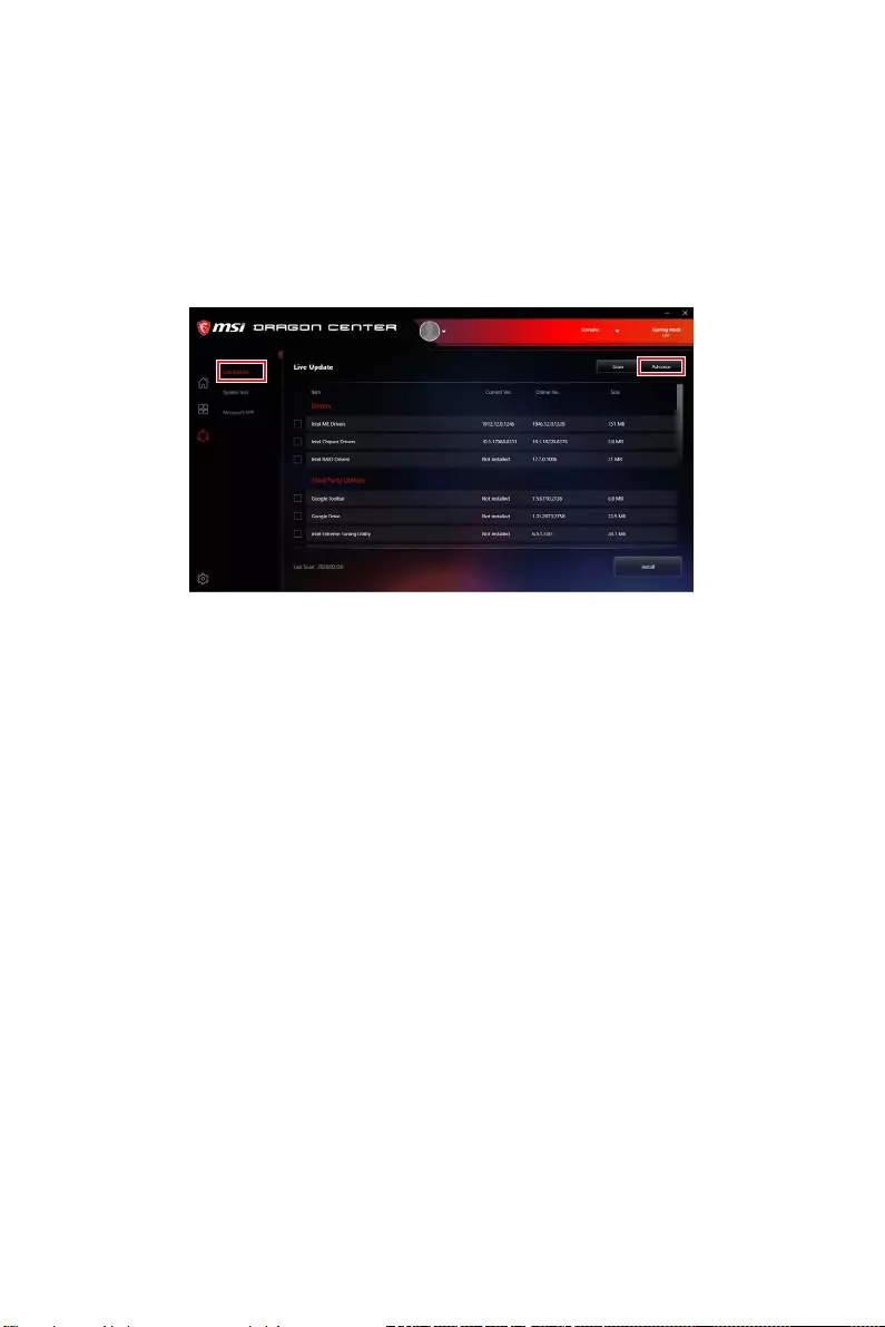
Updating the BIOS with MSI DRAGON CENTER
Before updating:
Make sure the LAN driver is already installed and the internet connection is set
properly.
Updating BIOS:
1. Install and launch MSI DRAGON CENTER and go to Support page.
2. Select Live Update and click on Advance button.
3. Click on Scan button to search the latest BIOS file.
4. Select the BIOS file and click on Download icon to download and install the latest
BIOS file.
5. Click Next and choose In Windows mode. And then click Next and Start to start
updating BIOS.
6. After the flashing process is 100% completed, the system will restart
automatically.
Updating BIOS with Flash BIOS Button
1. Please download the latest BIOS file that matches your motherboard model from
the MSI® website.
2. Rename the BIOS file to MSI.ROM, and save it to the root of your USB flash drive.
3. Connect the power supply to CPU_PWR1 and ATX_PWR1. (No need to install CPU
and memory.)
4. Plug the USB flash drive that contains the MSI.ROM file into the Flash BIOS Port
on the rear I/O panel.
5. Press the Flash BIOS Button to flash BIOS, and the LED starts flashing.
6. The LED will be turned off when the process is completed.
44 UEFI BIOS
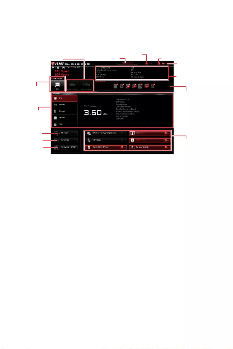
EZ Mode
At EZ mode, it provides the basic system information and allows you to configure the
basic setting. To configure the advanced BIOS settings, please enter the Advanced
Mode by pressing the Setup Mode switch or F7 function key.
A-XMP Profile
Component
Information
System
information
Boot device
priority bar
Function
buttons
Language
GAME BOOST
Search
Screenshot
Setup Mode switch
M-Flash
Hardware
Monitor
Favorites
∙GAME BOOST — click on it to toggle the GAME BOOST for overclocking. This function
is only available when both of the motherboard and CPU are supporting this function.
⚠
Important
We don’t recommend you to adjust any BIOS item after activating the GAME BOOST
function for keeping the optimal performance and system stability.
∙A-XMP Profile — allows you to select the A-XMP profile for memory to overclock.
This function is only available when the system, memory and CPU are supporting this
function.
∙Setup Mode switch — press this tab or the F7 key to switch between Advanced mode
and EZ mode.
∙Screenshot — click on this tab or the F12 key to take a screenshot and save it to USB
flash drive (FAT/ FAT32 format only).
∙Search — click on this tab or the Ctrl+F keys to enter the search page. It allows you
to search by BIOS item name. Move the mouse over a blank space and right click the
mouse to exit the search page.
⚠
Important
In search page, only the F6, F10 and F12 function keys are available.
∙Language — allows you to select language of BIOS setup.
45
UEFI BIOS
∙System information — shows the CPU/ DDR speed, CPU/ MB temperature, MB/ CPU
type, memory size, CPU/ DDR voltage, BIOS version and build date.
∙Boot device priority bar — you can move the device icons to change the boot priority.
The boot priority from high to low is left to right.
∙Component Information — click on the CPU, Memory, Storage, Fan Info and Help
buttons to show the information of connected component.
∙Function buttons — enable or disable these functions by clicking on these buttons.
The function is enabled when the button shows ON .
⚠
Important
The function buttons will vary with the motherboard you purchased.
∙M-Flash — click on this button to enter the M-Flash menu that provides the way to
update BIOS with a USB flash drive.
∙Hardware Monitor — click on this button to enter the Hardware Monitor menu that
allows you to manually control the fan speed by percentage.
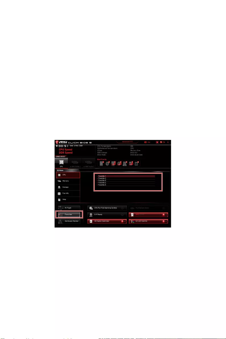
∙Favorites — click on this button or press the F3 key to show the Favorites window.
It provides 5 menus for you to create personal BIOS menu where you can save and
access favorite/ frequently-used BIOS setting items.
46 UEFI BIOS
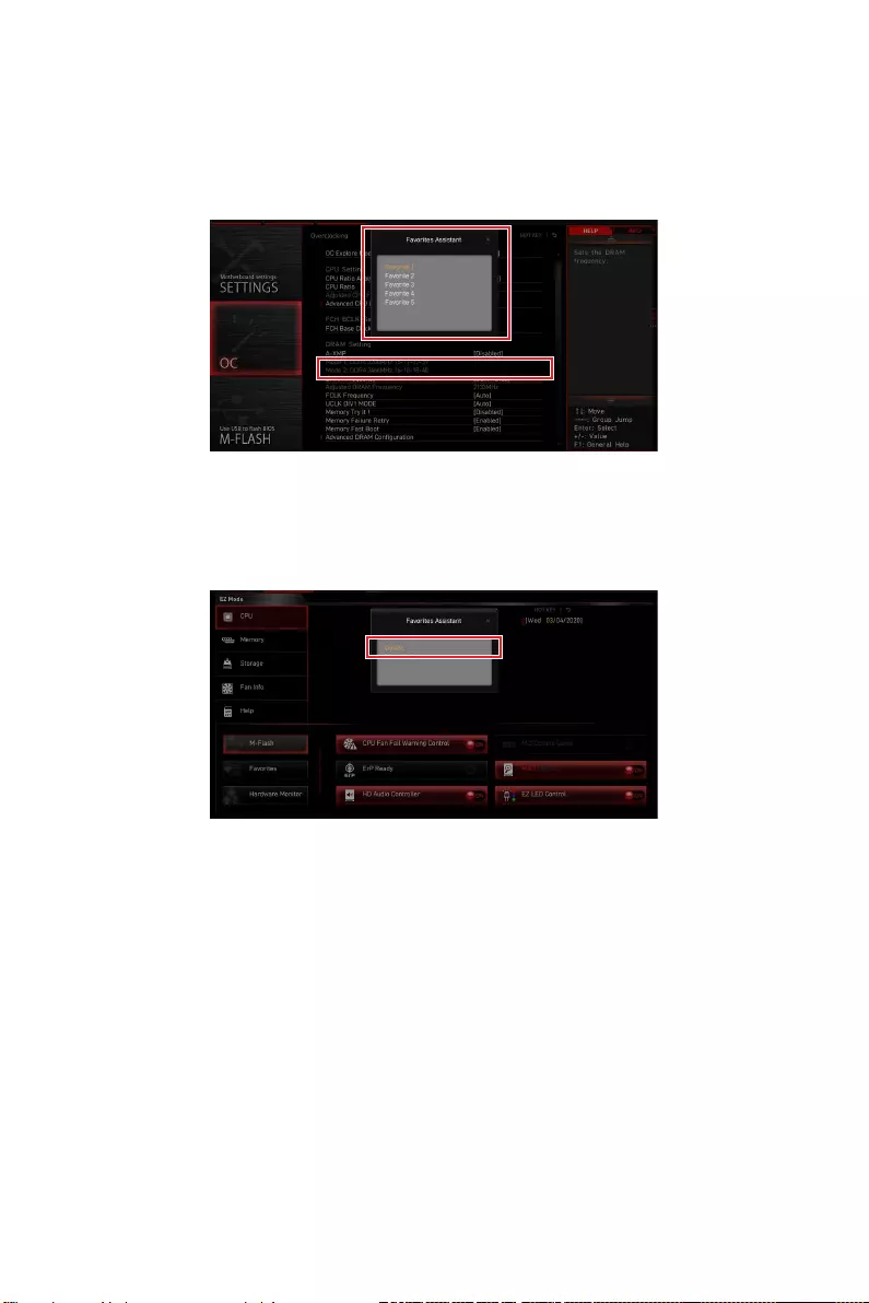
▪To add a BIOS item to a favorite menu
1. Select a BIOS item not only on BIOS menu but also on search page.
2. Right-click or press F2 key.
3. Choose a favorite page and click on OK.
▪To delete a BIOS item from favorite menu
1. Select a BIOS item on favorite menu.
2. Right-click or press F2 key.
3. Choose Delete and click on OK.
47
UEFI BIOS
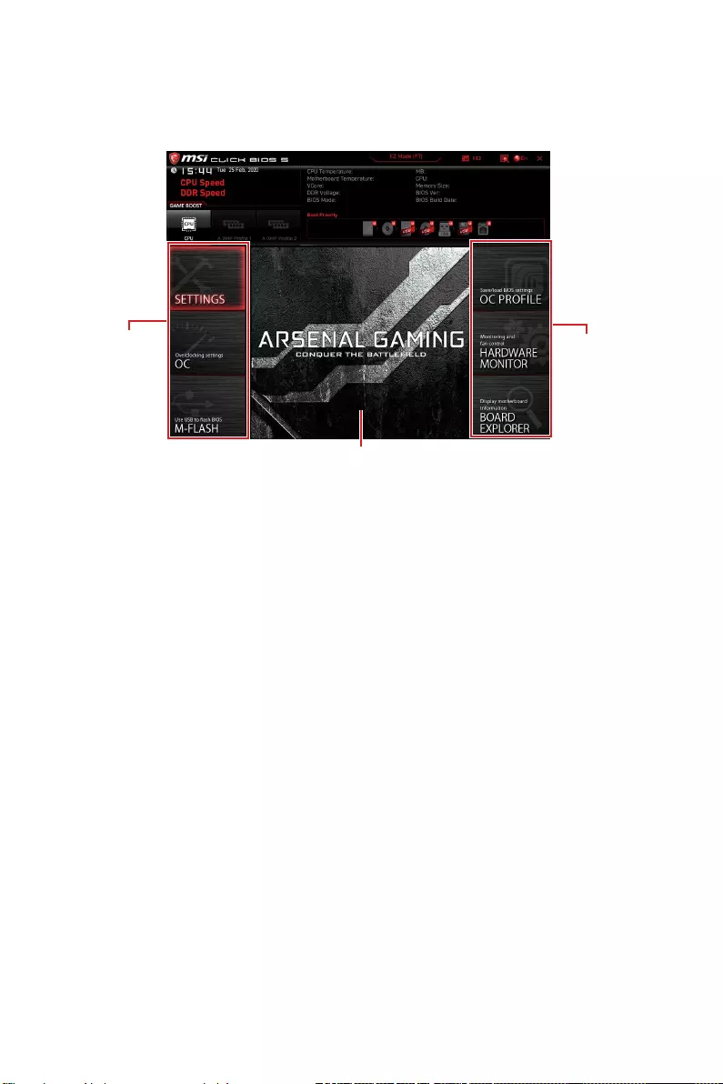
Advanced Mode
Press Setup Mode switch or F7 function key can switch between EZ Mode and
Advanced Mode in BIOS setup.
BIOS menu
selection
Menu display
BIOS menu
selection
∙BIOS menu selection — the following options are available:
▪SETTINGS — allows you to specify the parameters for chipset and boot devices.
▪OC — allows you to adjust the frequency and voltage. Increasing the frequency
may get better performance.
▪M-FLASH — provides the way to update BIOS with a USB flash drive.
▪OC PROFILE — allows you to manage overclocking profiles.
▪HARDWARE MONITOR — allows you to set the speeds of fans and monitor
voltages of system.
▪BOARD EXPLORER — provides the information of installed devices on this
motherboard.
∙Menu display — provides BIOS setting items and information to be configured.

48 UEFI BIOS
SETTINGS Menu
This menu allows you to specify the parameters for system, chipset and boot devices.
▶System Status sub-menu
The System Status sub-menu allows you to set the system clock and view system
information.
▶System Date
Sets the system date. Use tab key to switch between date elements.
The format is <day> <month> <date> <year>.
<day> Day of the week, from Sun to Sat, determined by BIOS. Read-only.
<month> The month from Jan. through Dec.
<date> The date from 1 to 31 can be keyed by numeric function keys.
<year> The year can be adjusted by users.
▶System Time
Sets the system time. Use tab key to switch between time elements.
The time format is <hour> <minute> <second>.
▶SATA PortX/ M2_X
Shows the information of connected SATA/ M.2 device.
⚠
Important
If the connected SATA/ M.2 device is not displayed, turn off computer and re-check
SATA/ M.2 cable and power cable connections of the device and motherboard.
▶System Information
Shows detailed system information, including CPU type, BIOS version, and Memory
(read only).
▶DMI Information
Shows system information, desktop board information and chassis information.
▶Advanced sub-menu
The Advanced sub-menu allows you to adjust and set the parameters and behaviors of
PCIe, ACPI, integrated peripherals, integrated graphics, USB, power management and
Windows .
▶PCI Subsystem Settings
Sets PCI, PCI express interface protocol and latency timer. Press Enter to enter
the sub-menu.
▶ACPI Settings
Sets ACPI parameters of onboard power LED behaviors.
▶Integrated Peripherals sub-menu
Sets integrated peripherals’ parameters, such as LAN, Wi-Fi, HDD, SSD, USB and
audio.

49
UEFI BIOS
▶Integrated Graphics Configuration sub-menu (optional)
Adjusts integrated graphics settings for optimum system. This sub-menu is only
available when using the CPU which integrate with IGP.
▶USB Configuration sub-menu
Sets the onboard USB controller and device function. Press Enter to enter the
sub-menu.
▶Super IO Configuration
Sets system Super I/O chip parameters including LPT and COM ports. Press Enter
to enter the sub-menu.
▶Power Management Setup sub-menu
Sets system Power Management of ErP and AC Power Loss behaviors. You can
optimize the system power consumption in this menu.
▶Windows OS Configuration
boot and control key management to prevent the unauthorized accessing for
system.
▶Wake Up Event Setup sub-menu
▶Secure Erase+
Enables or disables Secure Erase+ function. Secure Erase+ is the best way to
after enabling Secure Erase+.
▶Realtek PCIe GbE Family Controller (MAC sub-menu)
controller parameter.
▶Boot sub-menu
Use this menu to set the system boot states and the sequence of system boot devices.
▶Security sub-menu
Use this menu to set the administrator password and the user password for system
security. This menu also allows you to set the TPM (Trusted Platform Module)
function.
⚠
Important
When selecting the Administrator / User Password items, a password box will appear
on the screen. Type the password then press Enter. The password typed now will
replace any previous set password from CMOS memory. You will be prompted to
confirm the password. You may also press Esc key to abort the selection.
To clear a set password, press Enter when you are prompted to enter a new
password. A message will confirm the password is being disabled. Once the password
is disabled, you can enter the setup and OS without authorization.
▶Save & Exit
This menu allows you to load the BIOS default values or factory default settings into
the BIOS and exit the BIOS setup utility with or without changes.

50 UEFI BIOS
OC Menu
This menu allows you to configure the frequencies and voltages for overclocking.
Please note that, higher frequency and voltage may benefit overclocking capability but
cause system un-stability.
⚠
Important
∙
Overclocking your PC manually is only recommended for advanced users.
∙
Overclocking is not guaranteed, and if done improperly, it could void your warranty
or severely damage your hardware.
∙
If you are unfamiliar with overclocking, we advise you to use GAME BOOST function
for easy overclocking.
∙
The BIOS items in OC menu will vary with the processor.
▶OC Explore Mode [Normal]
Enables or disables to show the normal or expert version of OC settings.
[Normal] Provides the regular OC settings in BIOS setup.
[Expert] Provides the advanced OC settings for OC expert to configure in BIOS
setup.
Note: We use * as the symbol for the OC settings of Expert mode.
▶CPU Ratio [Auto]
Sets the CPU ratio that is used to determine CPU clock speed. This item can only be
changed if the processor supports this function.
▶ Advanced CPU Conguration
Press Enter to enter the sub-menu. User can set the parameters about CPU
power/ current. The system may become unstable or unbootable after changing the
parameters. If it occurs, please clear the CMOS data and restore the default settings.
▶A-XMP [Disabled]
Please enable A-XMP or select a profile of memory module for overclocking the
memory. This item will be available when the installed processor, memory modules
and motherboard support this function.
▶DRAM Frequency [Auto]
Sets the DRAM frequency. Please note the overclocking behavior is not guaranteed.
▶Adjusted DRAM Frequency
Shows the adjusted DRAM frequency. Read-only.
▶Memory Try It ! [Disabled]
It can improve memory compatibility or performance by choosing optimized memory
preset. This item will be available when the installed processor supports this function.
▶ Advanced DRAM Conguration
Press Enter to enter the sub-menu. User can set the memory timing for each/ all
memory channel. The system may become unstable or unbootable after changing
memory timing. If it occurs, please clear the CMOS data and restore the default
settings. (Refer to the Clear CMOS jumper section to clear the CMOS data, and enter

51
UEFI BIOS
the BIOS to load the default settings.)
▶DigitALL Power sub-menu
Press Enter to enter the sub-menu. In the sub-menu, you can setup some protecting
conditions about voltage/ current/ temputure for CPU.
▶CPU Voltages control [Auto]
These options allows you to set the voltages related to CPU. If set to Auto, BIOS will
set these voltages automatically or you can set it manually.
▶DRAM Voltages control [Auto]
These options allows you to set the voltages related to memory. If set to Auto, BIOS
will set these voltages automatically or you can set it manually.
▶Memory Changed Detect [Enabled]*
Enables or disables the system to issue a warning message during boot when the
memory has been replaced.
[Enabled] The system will issue a warning message during boot and then you have
to load the default settings for new devices.
[Disabled] Disables this function and keeps the current BIOS settings.
▶ CPU Specications sub-menu
Press Enter to enter the sub-menu. This sub-menu displays the information of
installed CPU. You can also access this information menu at any time by pressing [F4].
Read only.
▶MEMORY-Z sub-menu
Press Enter to enter the sub-menu. This sub-menu displays all the settings and
timings of installed memory. You can also access this information menu at any time by
pressing [F5].
52 UEFI BIOS
M-FLASH Menu
M-FLASH provides the way to update BIOS with a USB flash drive. Please download
the latest BIOS file that matches your motherboard model from MSI website, save the
BIOS file into your USB flash drive. And then follow the steps below to update BIOS.
1. Insert the USB flash drive that contains the update file into the computer.
2. Click on M-FLASH tab, a demand message will be prompted. Click on Yes to
reboot and enter the flash mode.
3. The system will enter the flash mode and a file selection menu will appear after
rebooting.
4. Select a BIOS file to perform the BIOS update process.
5. After the flashing process is 100% completed, the system will reboot
automatically.
53
UEFI BIOS
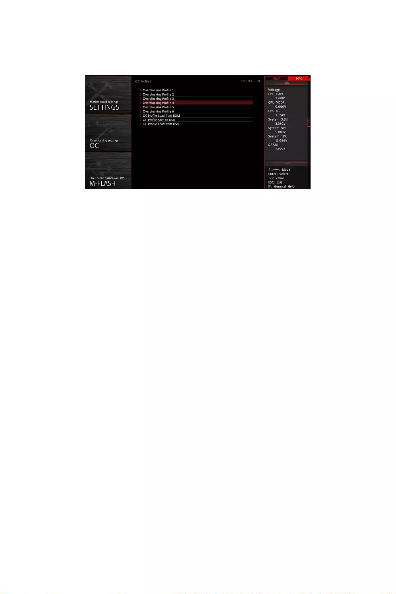
OC PROFILE Menu
▶ Overclocking Prole 1/ 2/ 3/ 4/ 5/ 6
Overclocking Profile 1/ 2/ 3/ 4/ 5/ 6 management. Press Enter to enter the sub-menu.
▶Set Name for Overclocking Profile 1/ 2/ 3/ 4/ 5/ 6
▶Save Overclocking Profile 1/ 2/ 3/ 4/ 5/ 6
▶Load Overclocking Profile 1/ 2/ 3/ 4/ 5/ 6
▶Clear Overclocking Profile 1/ 2/ 3/ 4/ 5/ 6
▶ OC Prole Load from ROM
Load OC profile from BIOS ROM.
▶ OC Prole Save to USB
Save OC profile to the USB flash drive. The USB flash drive should be FAT/ FAT32
format only.
▶ OC Prole Load from USB
Load OC profile from the USB flash drive. The USB flash drive should be FAT/ FAT32
format only.
54 UEFI BIOS
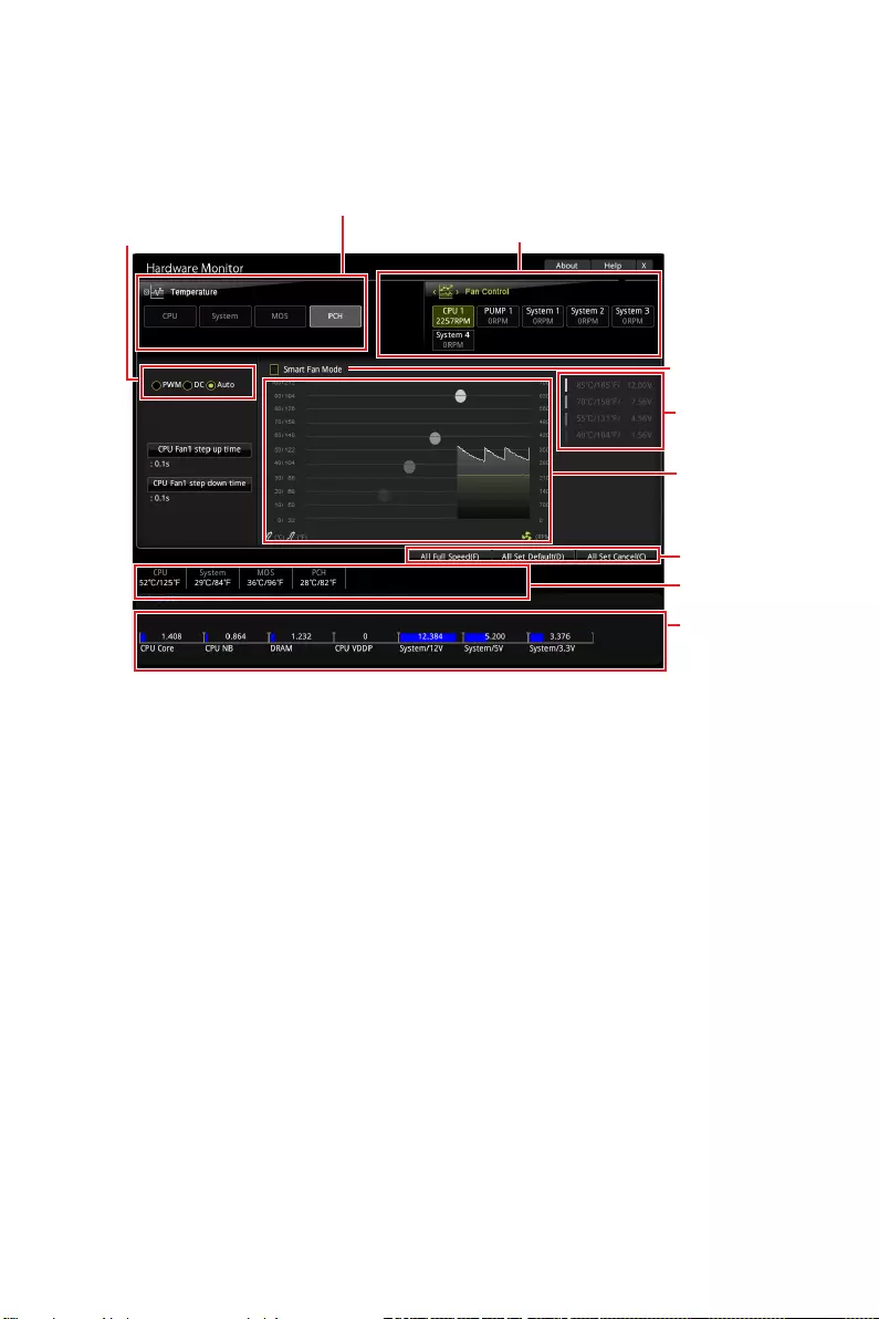
HARDWARE MONITOR Menu
This menu allows you to adjust the fan speed manually and monitor CPU/ system
voltage.
Fan operating
window
Smart Fan duty
information
Click to enable
the Smart Fan
Temperature
information
Setting Buttons
Select a fan to be configured
Select a temperature curve line (white)
to be showed in Fan operating window
Select a fan mode for target fan
Voltage
information
∙Smart Fan — This setting enables/disables the Smart Fan function. Smart Fan is an
excellent feature which will adjust the CPU/system fan speed automatically depending
on the current CPU/system temperature, avoiding the overheating to damage your
system.
▶Settings Buttons
▪All Full Speed — configures all fans to run at full operating speed.
▪All Set Default — configures all fans’ speeds return the BIOS default values.
▪All Set Cancel — discards current changes and restores previous settings for all
fan .
⚠
Important
Make sure fans are working properly after adjusting the fan speed and switching the
fan mode.
55
UEFI BIOS
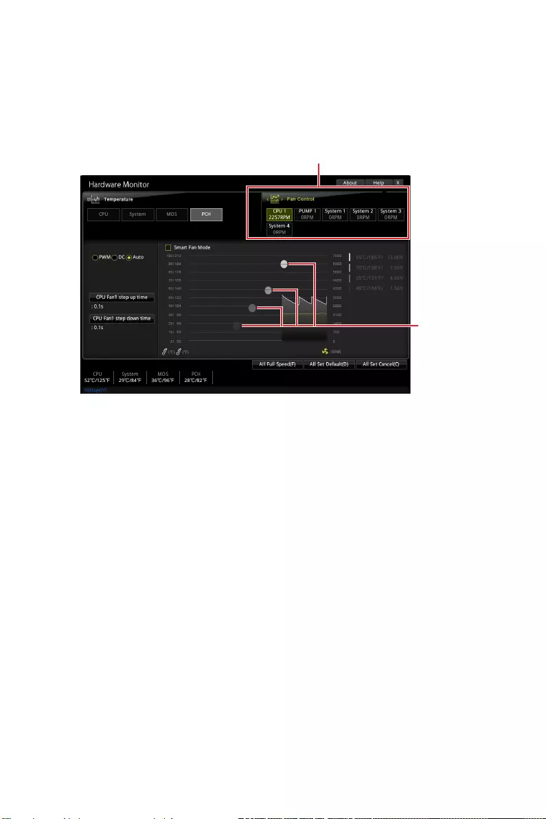
Adjusting fans
1. Selects a fan that you want to adjust and to display the fan duty curve line (yellow)
in fan operating windows.
2. Click and drag the duty points to adjust the fan speed.
Duty points
Select a fan to be adjusted
⚠
Important
The pictures in this section are for reference only and may vary from the motherboard
you purchased.
56 AMD RAID Configuration
AMD RAID Configuration
The following are the RAID levels supported by RAIDXpert2.
RAID 0 (Striping) breaks the data into blocks which are written to separate hard
drives. Spreading the hard drive I/O load across independent channels
greatly improves I/O performance.
RAID 1 (Mirroring) provides data redundancy by mirroring data between the hard
drives and provides enhanced read performance.
RAID 10 (Striped RAID1 Sets) uses four hard drives to create a combination of RAID 0
and 1 by forming a RAID 0 array from two RAID 1 arrays.
Volume (JBOD) provides the ability to link-together storage from one or several
disks, regardless of the size of the space on those disks. Useful in
scavenging space on disks unused by other disks in the array. Does not
provide performance benefits or data redundancy.
RAIDABLE (also known as RAID Ready) allows the user to add more storage space or
create a redundant array after a system is installed.
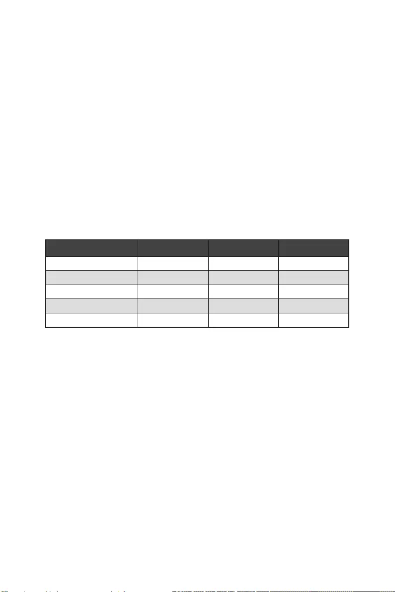
RAID level comparison
RAID 0 RAID 1 RAID 10
Minimum # drives 2 2 4
Data protection None Excellent Excellent
Read performance Excellent OK OK
Write performance Excellent Good Good
Capacity utilization 100% 50% 50%
⚠
Important
All the information/ volumes/ pictures listed in your system might differ from the
illustrations in this appendix.
Enabling RAIDXpert2 Configuration Utility
To enter the RAIDXpert2 Configuration Utility menu
1. Power on and press Delete key to enter BIOS Setup menu.
2. Press F7 to switch to Advanced mode from EZ mode.
3. Go to BIOS > SETTINGS > Advanced > Integrated Peripherals > SATA Mode and
change setting to RAID Mode.
4. Go to BIOS > SETTINGS > Advanced > Windows OS Configuration > BIOS UEFI/
CSM Mode and change setting to UEFI.
5. Press F10 to save configuration and exit, and then reboot and press Delete key to
enter BIOS Setup menu.
6. Go to BIOS > SETTINGS > Advanced > RAIDXpert2 Configuration Utility sub-
menu.
57
AMD RAID Configuration
Initializing Disks
New disks and legacy disks must be initialized before they can be used to create an
AMD-RAID array. Initialization writes AMD-RAID configuration information (metadata)
to a disk.
⚠
Important
∙
If a disk is part of an AMD-RAID array, the disk cannot be selected for initialization.
To initial the disk anyway, delete the AMD-RAID array. Data on the disk is deleted
during initialization so ensure the correct disks are chosen to initialize.
∙
A legacy disk can contain valid data. When a legacy disk is initialized, all data on the
disk is lost.
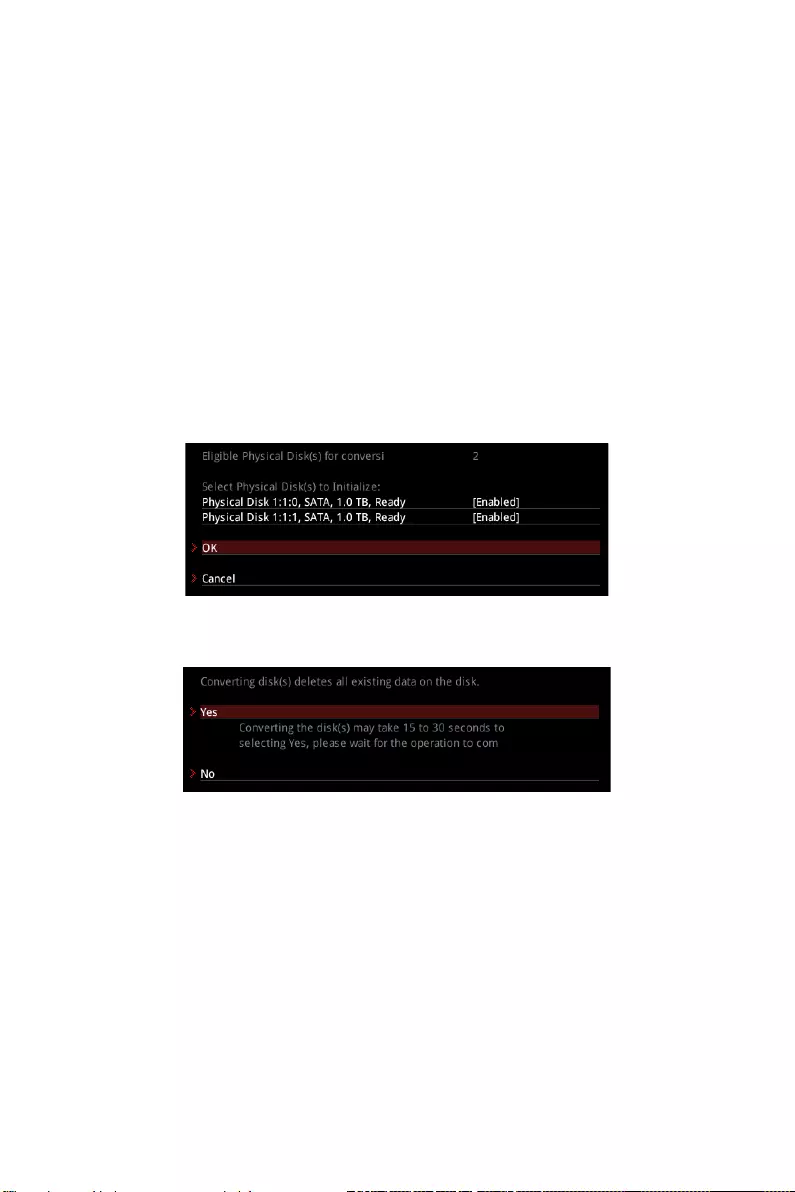
To initialize disks
1. As previously mentioned, enable RAIDXpert2 Configuration Utility.
2. Go to BIOS > SETTINGS > Advanced > RAIDXpert2 Configuration Utility > Physical
Disk Management > Select Physical Disk Operations > Initialize Disk sub-menu.
3. Select desired disks by changing the Physical Disk setting to Enabled.
4. Select OK, then press Enter.
5. Review the warning message, if you want to proceed, select YES, then press Enter.
6. Initialization takes 10 to 15 seconds per disk. During initialization, a complete
rescan of all channels is done automatically.
58 AMD RAID Configuration
Creating Arrays
Arrays can be created after the disks are initialized.
⚠
Important
∙
For redundant arrays, the Create process is not started until after the operating
system and AMD-RAID OS drivers have been installed and the system has booted to
the operating system. However, the arrays are immediately available to use for either
a bootable array or a data array.
∙
Array numbers are valid only for a given boot and might be different in the
RAIDXpert2 Configuration Utility and RAIDXpert2. If a permanent label is required, use
the RAIDXpert2 Web GUI Array Naming feature.
∙
At any point in the procedure, return to a prior window by pressing ESC.
∙
If the system is booted from an AMD-RAID bootable array, the first array in the
Arrays section must be the bootable array. The system boots only from the first array
in the Arrays section.
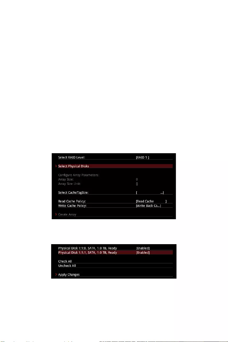
To create an array
1. As previously mentioned, enable RAIDXpert2 Configuration Utility.
2. Go to BIOS > SETTINGS > Advanced > RAIDXpert2 Configuration Utility > Array
Management > Create Array sub-menu.
3. Select the RAID level from the Select RAID Level drop down menu.
4. Enter Select Physical Disks sub-menu, select member disks by changing the
Physical Disk setting to Enabled.
5. Select Apply Changes, then press Enter to apply and go back to previous sub-
menu.
6. Change the Select CacheTagSize, Read Cache Policy and Write Cache Policy
settings according to your needs.
7. Select Create Array, then press Enter.
59
AMD RAID Configuration
Deleting Arrays
⚠
Important
∙
Deleting an array permanently destroys all data that is on the array. This action
cannot be undone and it is very unlikely that the data can be recovered.
∙
Do not delete the first array listed in the Arrays section, if it is the AMD-RAID
bootable array. Doing this deletes the operating system and AMD-RAID files.
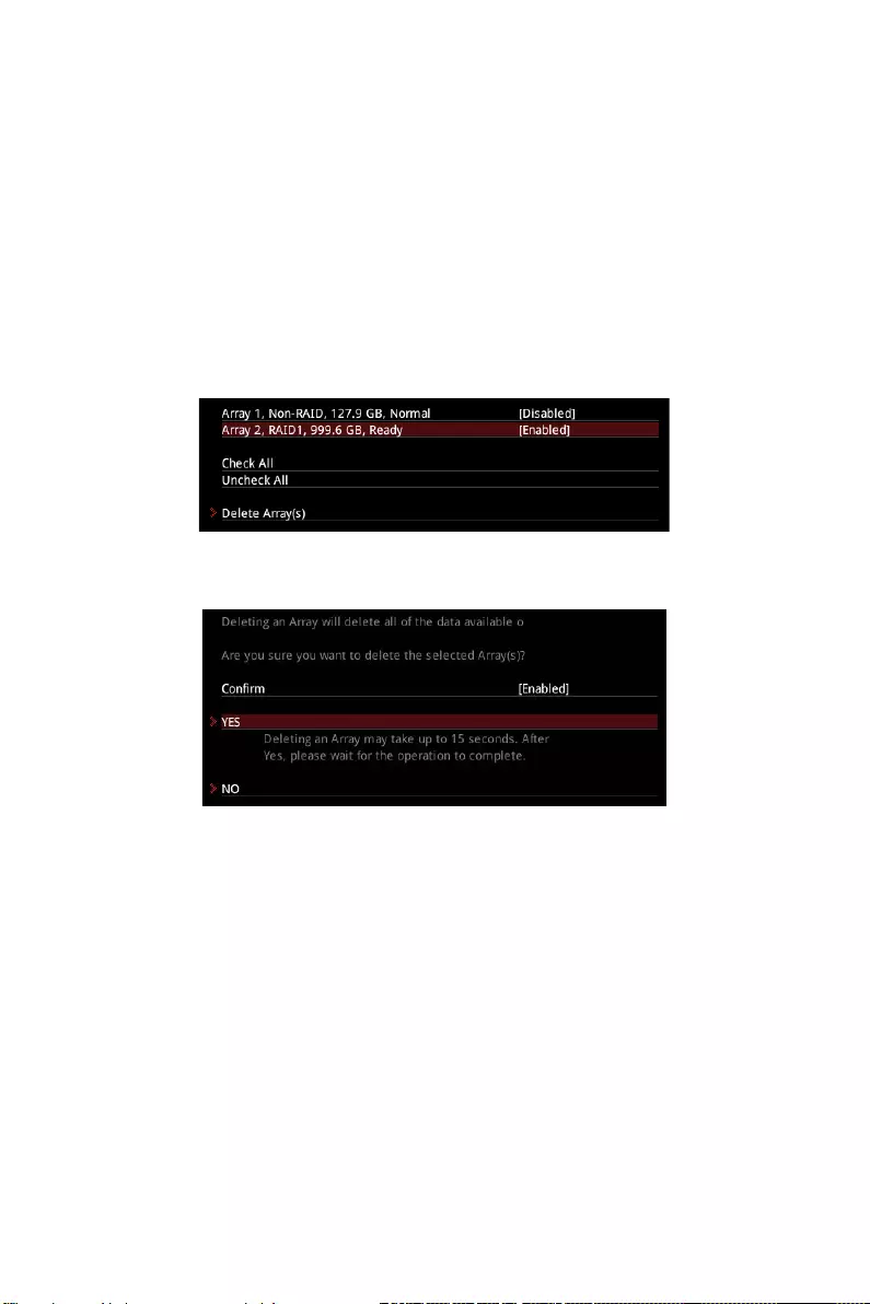
To delete an array
1. As previously mentioned, enable RAIDXpert2 Configuration Utility.
2. Go to BIOS > SETTINGS > Advanced > RAIDXpert2 Configuration Utility > Array
Management > Delete Array sub-menu.
3. Select the desired array and change the setting to Enabled.
4. Enter Delete Array(s) sub-menu.
5. Review the warning message, if you want to proceed, Select Confirm and change
the setting to Enabled.
6. Select YES then press Enter.

60 AMD RAID Configuration
Installing RAID Driver
New Operating System Installation
The following details the installation of the drivers while installing operating system.
1. During the operating system installation, after selecting the location to install
Windows click on Load driver button to install a third party RAID driver.
2. When prompted, insert the USB flash drive with AMD RAID Drivers and then click
Browse.
▪To make an AMD RAID Drivers USB flash drive. Insert the MSI Driver Disc into
the optical drive. Copy all the contents in \\Storage\AMD\
3. Navigate to the directory containing the saved AMD RAID drivers, then click OK.
4. Select the (rcbottom.inf) driver, click Next.
5. When prompted, click OK.
6. Click Browse and navigate to the directory containing the saved AMD RAID drivers
again, then click OK.
7. Select the (rcraid.inf) driver, click Next.
8. You have successfully installed the RAID driver, and Windows setup should
continue.
9. Leave the disk/ USB drive in the computer until the system reboots itself.
Windows setup will need to copy the files after the RAID volume is formatted, and
Windows setup starts copying files.
AMD RAIDXpert2 Management Suite Installation
1. Set the SATA Mode to RAID Mode in BIOS
2. Insert the MSI Driver Disc into the optical drive.
3. Click the Select to choose what happens with this disc pop-up notification, then
select Run DVDSetup.exe to open the installer. If you turn off the AutoPlay feature
from the Windows Control Panel, you can still manually execute the DVDSetup.
exe from the root path of the MSI Driver Disc.
4. Under the Drivers/Software tab, check the AMD RAID Drivers check-box.
5. Click the Install button.
6. When prompt you to restart, click OK button to finish.
7. Restart your computer and enter the Windows operating system.
8. Double-click the RAIDXpert2 icon to open the RAIDXpert2 Web GUI.
▪Default credentials are:
▫Username — admin
▫Password — admin
9. Change the credentials:
▪Create new username and password
10. Re-log into the RAIDXpert2 Web GUI with the new credentials.

Troubleshooting
Before sending the motherboard for RMA
repair, try to go over troubleshooting
guide first to see if your got similar
symptoms as mentioned below.
The power is not on.
∙Connect the AC power cord to an
electrical outlet securely.
∙Check if all ATX power connectors
like ATX_PWR1, CPU_PWR1 are
connected from the power supply to the
motherboard?
∙Some power supply units have a power
button on the rear side, make sure the
button is turned on.
∙Check if the power switch cable is
connected to JFP1 pin header properly.
∙Verify the Clear CMOS jumper JBAT1 is
set to Keep DATA.
∙Test with another known working
power supply of equal or greater
wattage.
The power is on, but no signal to
monitor
∙Connect the monitor power cord to a
electrical outlet securely.
∙Make sure the monitor is turned on.
∙Select different inputs on the monitor.
∙If 3 long beeps are heard, remove all
memory modules and try to install only
one memory module in the DIMMA2 slot
first and then restart the computer.
∙If 1 long 2 short beeps are heard,
remove and reinstall the graphics card
and then restart the computer.
∙Test with another known working
graphics card.
The computer does not boot after
updating the BIOS
∙Clear the CMOS.
∙Use the secondary BIOS to bootup the
system (Only for motherboard with Dual
BIOS)
Lost BIOS password
∙Clear the CMOS, but that will cause
you to lose all customized settings in the
BIOS.
There is no audio
∙Adjust the volume.
∙Connect the speakers/headphones to
audio ports on the motherboard rear IO
panel.
∙Remove secondary speakers/
headphones, HDMI cables, USB audio
devices.
∙Test with another known working
speaker or headphone.
There is no network
∙Make sure the network chipset driver
has been installed.
∙Verify if the network cable is properly
connected and make sure the LAN port
LEDs are properly illuminated.
∙Verify your TCP/IP settings.
∙Restart or reset your router.
∙Test with another known working LAN
cable.
The USB device is not working
∙Make sure your USB drive driver has
been installed.
∙Verify if USB device is listed in
Windows® Device Manager.
∙Connect the USB device to other USB
port on the motherboard rear IO panel.
61
Troubleshooting
i
Regulatory Notices
FCC Compliance Statement
Note: This equipment has been tested and found to
comply with the limits for a Class B digital device,
pursuant to part 15 of the FCC Rules. These limits are
designed to provide reasonable protection against
harmful interference in a residential installation. This
equipment generates, uses and can radiate radio
frequency energy and, if not installed and used in
accordance with the instructions, may cause harmful
interference to radio communications. However, there
is no guarantee that interference will not occur in a
particular installation. If this equipment does cause
harmful interference to radio or television reception,
which can be determined by turning the equipment
off and on, the user is encouraged to try to correct the
interference by one or more of the following measures:
· Reorient or relocate the receiving antenna.
· Increase the separation between the equipment
and receiver.
· Connect the equipment into an outlet on a circuit
different from that to which the receiver is
connected.
· Consult the dealer or an experienced radio/TV
technician for help.
Caution: Changes or modifications not expressly
approved by the party responsible for compliance could
void the user’s authority to operate the equipment.
Tested to comply with FCC standards
FOR HOME OR OFFICE USE
This device complies with part 15 of the FCC Rules.
Operation is subject to the following two conditions:
(1) This device may not cause harmful interference,
and (2) this device must accept any interference
received, including interference that may cause
undesired operation.
CE Conformity
Products bearing the CE marking comply
with one or more of the following EU
Directives as may be applicable:
RED 2014/53/EU; Low Voltage Directive 2014/35/EU;
EMC Directive 2014/30/EU; RoHS Directive 2011/65/EU.
Compliance with these directives is assessed using
applicable European Harmonized Standards.
The point of contact for regulatory matters is MSI,
MSI-NL Eindhoven 5706 5692 ER Son.
KC인증서
クラスB情報技術装置
VCCI-B
C-Tick Compliance
Battery Information
European Union:
Batteries, battery packs, and
accumulators should not be disposed of as
unsorted household waste. Please use the
public collection system to return, recycle,
or treat them in compliance with the local
regulations.
Taiwan:
For better environmental protection,
waste batteries should be collected
separately for recycling or special
disposal.
California, USA:
The button cell battery may contain
perchlorate material and requires special
handling when recycled or disposed of in
California.
For further information please visit:
http://www.dtsc.ca.gov/hazardouswaste/perchlorate/
CAUTION: There is a risk of explosion, if battery is
incorrectly replaced.
Replace only with the same or equivalent type
recommended by the manufacturer.
Chemical Substances Information
In compliance with chemical substances regulations,
such as the EU REACH Regulation (Regulation EC
No. 1907/2006 of the European Parliament and the
Council), MSI provides the information of chemical
substances in products at:
https://storage-asset.msi.com/html/popup/csr/
evmtprtt_pcm.html
Environmental Policy
· The product has been designed to
enable proper reuse of parts and
recycling and should not be thrown
away at its end of life.
· Users should contact the local
authorized point of collection for recycling and
disposing of their end-of-life products.
· Visit the MSI website and locate a nearby distributor
for further recycling information.
· Users may also reach us at gpcontdev@msi.com for
information regarding proper Disposal, Take-back,
Recycling, and Disassembly of MSI products.
WEEE (Waste Electrical and
Electronic Equipment) Statement
ENGLISH
To protect the global environment and as
an environmentalist, MSI must remind
you that…
Under the European Union (“EU”) Directive
R-REI-MSI-MS-7C02

ii
on Waste Electrical and Electronic Equipment,
Directive 2002/96/EC, which takes effect on August 13,
2005, products of “electrical and electronic equipment”
cannot be discarded as municipal wastes anymore, and
manufacturers of covered electronic equipment will
be obligated to take back such products at the end of
their useful life. MSI will comply with the product take
back requirements at the end of life of MSI-branded
products that are sold into the EU. You can return
these products to local collection points.
DEUTSCH
Hinweis von MSI zur Erhaltung und Schutz unserer
Umwelt
Gemäß der Richtlinie 2002/96/EG über Elektro- und
Elektronik-Altgeräte dürfen Elektro- und Elektronik-
Altgeräte nicht mehr als kommunale Abfälle entsorgt
werden. MSI hat europaweit verschiedene Sammel-
und Recyclingunternehmen beauftragt, die in die
Europäische Union in Verkehr gebrachten Produkte,
am Ende seines Lebenszyklus zurückzunehmen.
Bitte entsorgen Sie dieses Produkt zum gegebenen
Zeitpunkt ausschliesslich an einer lokalen
Altgerätesammelstelle in Ihrer Nähe.
FRANÇAIS
En tant qu’écologiste et afin de protéger
l’environnement, MSI tient à rappeler ceci…
Au sujet de la directive européenne (EU) relative aux
déchets des équipement électriques et électroniques,
directive 2002/96/EC, prenant effet le 13 août 2005, que
les produits électriques et électroniques ne peuvent
être déposés dans les décharges ou tout simplement
mis à la poubelle. Les fabricants de ces équipements
seront obligés de récupérer certains produits en fin
de vie. MSI prendra en compte cette exigence relative
au retour des produits en fin de vie au sein de la
communauté européenne. Par conséquent vous pouvez
retourner localement ces matériels dans les points
de collecte.
РУССКИЙ
ESPAÑOL
MSI como empresa comprometida con la protección
del medio ambiente, recomienda:
Bajo la directiva 2002/96/EC de la Unión Europea
en materia de desechos y/o equipos electrónicos,
con fecha de rigor desde el 13 de agosto de 2005,
los productos clasificados como “eléctricos y
equipos electrónicos” no pueden ser depositados
en los contenedores habituales de su municipio, los
fabricantes de equipos electrónicos, están obligados
a hacerse cargo de dichos productos al termino de
su período de vida. MSI estará comprometido con los
términos de recogida de sus productos vendidos en
la Unión Europea al final de su periodo de vida. Usted
debe depositar estos productos en el punto limpio
establecido por el ayuntamiento de su localidad o
entregar a una empresa autorizada para la recogida de
estos residuos.
NEDERLANDS
Om het milieu te beschermen, wil MSI u eraan
herinneren dat….
De richtlijn van de Europese Unie (EU) met betrekking
tot Vervuiling van Electrische en Electronische
producten (2002/96/EC), die op 13 Augustus 2005 in
zal gaan kunnen niet meer beschouwd worden als
vervuiling. Fabrikanten van dit soort producten worden
verplicht om producten retour te nemen aan het
eind van hun levenscyclus. MSI zal overeenkomstig
de richtlijn handelen voor de producten die de
merknaam MSI dragen en verkocht zijn in de EU. Deze
goederen kunnen geretourneerd worden op lokale
inzamelingspunten.
SRPSKI
vas podesti da…
EC, koja stupa na snagu od 13. Avgusta 2005, proizvodi
proizvoda kojima je istekao vek trajanja, koji imaju MSI
vratiti na lokalnim mestima za prikupljanje.
POLSKI
odpadów produktów elektrycznych i elektronicznych
(sprzedawane na terenie Unii Europejskiej) wycofywane
wyznaczonych punktach zbiorczych.
TÜRKÇE

iii
ČESKY
EC platné od 13. srpna 2005 je zakázáno likvidovat
komunálním odpadu a výrobci elektronických
MAGYAR
Annak érdekében, hogy környezetünket megvédjük,
Önt, hogy …
Az Európai Unió („EU”) 2005. augusztus 13-án hatályba
hulladékairól szóló 2002/96/EK irányelve szerint
az elektromos és elektronikus berendezések
és az ilyen elektronikus berendezések gyártói
kötelessé válnak az ilyen termékek visszavételére
azok hasznos élettartama végén. Az MSI betartja a
termékvisszavétellel kapcsolatos követelményeket
az MSI márkanév alatt az EU-n belül értékesített
termékek esetében, azok élettartamának végén. Az
ITALIANO
Per proteggere l’ambiente, MSI, da sempre amica della
natura, ti ricorda che….
In base alla Direttiva dell’Unione Europea (EU) sullo
Smaltimento dei Materiali Elettrici ed Elettronici,
Direttiva 2002/96/EC in vigore dal 13 Agosto 2005,
prodotti appartenenti alla categoria dei Materiali
Elettrici ed Elettronici non possono più essere eliminati
come rifiuti municipali: i produttori di detti materiali
saranno obbligati a ritirare ogni prodotto alla fine
del suo ciclo di vita. MSI si adeguerà a tale Direttiva
ritirando tutti i prodotti marchiati MSI che sono stati
venduti all’interno dell’Unione Europea alla fine del
loro ciclo di vita. È possibile portare i prodotti nel più
vicino punto di raccolta
日本JIS C 0950材質宣言
https://storage-asset.msi.com/html/popup/csr/
cemm_jp.html
India RoHS
This product complies with the “India E-waste
(Management and Handling) Rule 2011” and prohibits
use of lead, mercury, hexavalent chromium,
polybrominated biphenyls or polybrominated diphenyl
ethers in concentrations exceeding 0.1 weight % and
0.01 weight % for cadmium, except for the exemptions
set in Schedule 2 of the Rule.
Türkiye EEE yönetmeliği
Україна обмеження на наявність
небезпечних речовин
Việt Nam RoHS
iv
MS-7C02主板产品中有害物质的名称及含量
(Pb)
(Hg)
(Cd)
(Cr(VI))
(PBB)
(PBDE)
限用物質含有情況標示聲明書
(Pb)
(Hg)
(Cd)
(Cr+6)
(PBB)
(PBDE)
Copyright
Micro-Star Int’l Co.,Ltd.
Copyright © 2020 All rights reserved.
The MSI logo used is a registered trademark of
Micro-Star Int’l Co., Ltd. All other marks and names
mentioned may be trademarks of their respective
owners. No warranty as to accuracy or completeness is
expressed or implied. MSI reserves the right to make
changes to this document without prior notice.
Revision History
Version 3.0, 2020/07, First release.
Version 3.1, 2020/09, Modify audio codec
Technical Support
If a problem arises with your system and no solution
can be obtained from the user guide, please
contact your place of purchase or local distributor.
Alternatively, please try the following help resources
for further guidance.
· Visit the MSI website for technical guide, BIOS
updates, driver updates, and other information:
http://www.msi.com
· Register your product at: http://register.msi.com
Материнская плата MSI B450 TOMAHAWK MAX II

AM4, AMD B450, 4xDDR4-2667 МГц, 2xPCI-Ex16, 1xM.2, Standard-ATX
подробнее

284
Код товара: 4741001
![]()
Quick Start
Thank you for purchasing the MSI® B450 TOMAHAWK MAX II motherboard. This Quick Start section provides demonstration diagrams about how to install your computer. Some of the installations also provide video demonstrations. Please link to the URL to watch it with the web browser on your phone or tablet. You may have even link to the URL by scanning the QR code.
Preparing Tools and Components
AMD® AM4 CPU
DDR4 Memory
|
Power Supply Unit |
Graphics Card |
Thermal Paste
|
SATA Hard Disk Drive |
SATA DVD Drive |
|
Phillips Screwdriver |
A Package of Screws |
Quick Start 1
Safety Information
∙∙The components included in this package are prone to damage from electrostatic discharge (ESD). Please adhere to the following instructions to ensure successful computer assembly.
∙∙Ensure that all components are securely connected. Loose connections may cause the computer to not recognize a component or fail to start.
∙∙Hold the motherboard by the edges to avoid touching sensitive components. ∙∙It is recommended to wear an electrostatic discharge (ESD) wrist strap when
handling the motherboard to prevent electrostatic damage. If an ESD wrist strap is not available, discharge yourself of static electricity by touching another metal object before handling the motherboard.
∙∙Store the motherboard in an electrostatic shielding container or on an anti-static pad whenever the motherboard is not installed.
∙∙Before turning on the computer, ensure that there are no loose screws or metal components on the motherboard or anywhere within the computer case.
∙∙Do not boot the computer before installation is completed. This could cause permanent damage to the components as well as injury to the user.
∙∙If you need help during any installation step, please consult a certified computer technician.
∙∙Always turn off the power supply and unplug the power cord from the power outlet before installing or removing any computer component.
∙∙Keep this user guide for future reference. ∙∙Keep this motherboard away from humidity.
∙∙Make sure that your electrical outlet provides the same voltage as is indicated on the PSU, before connecting the PSU to the electrical outlet.
∙∙Place the power cord such a way that people can not step on it. Do not place anything over the power cord.
∙∙All cautions and warnings on the motherboard should be noted.
∙∙If any of the following situations arises, get the motherboard checked by service personnel:
▪▪Liquid has penetrated into the computer.
▪▪The motherboard has been exposed to moisture.
▪▪The motherboard does not work well or you can not get it work according to user guide.
▪▪The motherboard has been dropped and damaged. ▪▪The motherboard has obvious sign of breakage.
∙∙Do not leave this motherboard in an environment above 60°C (140°F), it may damage the motherboard.
2 Quick Start
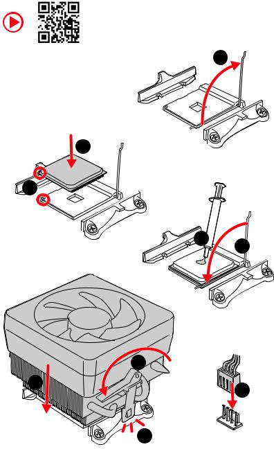
Installing a Processor
|
1 |
3
2 


5 4
|
6 |
8 |
|
|
9 |
||
|
7 |
Quick Start 3

Important
If you are installing the screw-type CPU heatsink, please follow the figure below to remove the retention module first and then install the heatsink.
1
4 Quick Start
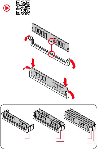
Installing DDR4 memory
|
DIMMA2 |
DIMMA2 |
DIMMA1 |
|
DIMMA2 |
||
|
DIMMB2 |
DIMMB1 |
|
|
DIMMB2 |
Quick Start 5
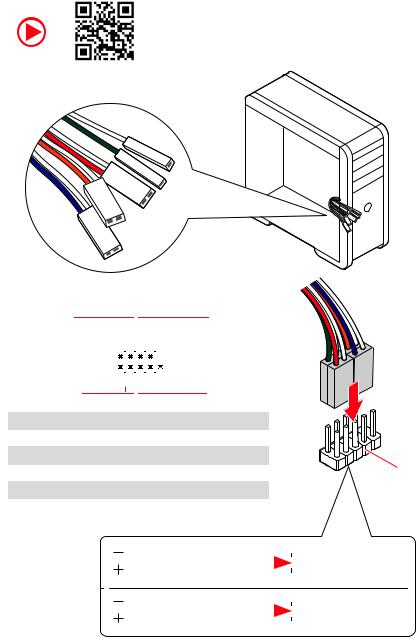
Connecting the Front Panel Header
|
— |
|||
|
LED |
|||
|
LED+ |
POWER |
||
|
POWER |
|||
|
LED |
|||
|
SW |
HDD |
||
|
POWER |
|||
|
SW |
|||
|
RESET |
|
Power LED |
Power Switch |
||||||||||||||||||
|
-+-+ |
|||||||||||||||||||
|
JFP1 |
2 |
10 |
|||||||||||||||||
|
1 |
9 |
Reserved |
|||||||||||||||||
|
+ — +- |
|||||||||||||||||||
|
HDD LED |
Reset Switch |
||||||||||||||||||
|
1 |
HDD LED + |
2 |
Power LED + |
||||||||||||||||
|
3 |
HDD LED — |
4 |
Power LED — |
||||||||||||||||
|
5 |
Reset Switch |
6 |
Power Switch |
||||||||||||||||
|
7 |
Reset Switch |
8 |
Power Switch |
||||||||||||||||
|
9 |
Reserved |
10 |
No Pin |
HDDLED RESETSW
|
HDD LED — |
|||||||
|
HDD LED |
|||||||
|
HDD LED + |
|||||||
|
POWER LED — |
|||||||
|
POWER LED |
POWER LED + |
||||||
6 Quick Start

Installing the Motherboard
BAT1
2
BAT1
*3 kgf·cm = 0.3 N·m = 2.6 lbf·in
Quick Start 7
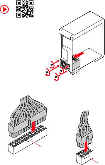
Connecting the Power Connectors
ATX_PWR1
CPU_PWR1
8 Quick Start
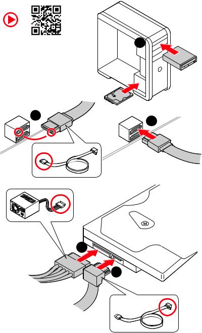
Installing SATA Drives
|
1 |
5
4
Quick Start 9
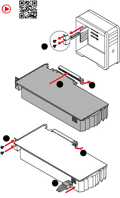
Installing a Graphics Card
1
5
 4
4
6
10 Quick Start
![]()
Connecting Peripheral Devices
Processor with Radeon™ Graphics
Quick Start 11
|
Contents |
|
|
Quick Start ………………………………………………………………………………………………. |
1 |
|
Preparing Tools and Components……………………………………………………………….. |
1 |
|
Safety Information …………………………………………………………………………………….. |
2 |
|
Installing a Processor………………………………………………………………………………… |
3 |
|
Installing DDR4 memory ……………………………………………………………………………. |
5 |
|
Connecting the Front Panel Header…………………………………………………………….. |
6 |
|
Installing the Motherboard…………………………………………………………………………. |
7 |
|
Connecting the Power Connectors………………………………………………………………. |
8 |
|
Installing SATA Drives………………………………………………………………………………… |
9 |
|
Installing a Graphics Card ………………………………………………………………………… |
10 |
|
Connecting Peripheral Devices …………………………………………………………………. |
11 |
|
Power On………………………………………………………………………………………………… |
12 |
|
Specifications…………………………………………………………………………………………. |
15 |
|
Package contents……………………………………………………………………………………. |
20 |
|
Block Diagram ………………………………………………………………………………………. |
21 |
|
Rear I/O Panel………………………………………………………………………………………… |
22 |
|
LAN Port LED Status Table……………………………………………………………………….. |
22 |
|
Audio Ports Configuration ………………………………………………………………………… |
22 |
|
Realtek Audio Console …………………………………………………………………………….. |
23 |
|
Overview of Components ………………………………………………………………………… |
25 |
|
Processor Socket…………………………………………………………………………………….. |
27 |
|
DIMM Slots……………………………………………………………………………………………… |
28 |
|
PCI_E1~5: PCIe Expansion Slots……………………………………………………………….. |
29 |
|
M2_1: M.2 Slot (Key M) …………………………………………………………………………….. |
30 |
|
SATA1~6: SATA 6Gb/s Connectors …………………………………………………………….. |
30 |
|
JFP1, JFP2: Front Panel Connectors …………………………………………………………. |
31 |
|
JAUD1: Front Audio Connector …………………………………………………………………. |
31 |
|
CPU_PWR1, ATX_PWR1: Power Connectors ………………………………………………. |
32 |
|
JUSB1~2: USB 2.0 Connectors………………………………………………………………….. |
33 |
|
JUSB3: USB 3.2 Gen 1 Connector ……………………………………………………………… |
33 |
|
CPU_FAN1, PUMP_FAN1, SYS_FAN1~4: Fan Connectors…………………………….. |
34 |
|
JCI1: Chassis Intrusion Connector…………………………………………………………….. |
35 |
|
JCOM1: Serial Port Connector ………………………………………………………………….. |
35 |
|
JTPM1: TPM Module Connector………………………………………………………………… |
36 |
|
JBAT1: Clear CMOS (Reset BIOS) Jumper ………………………………………………….. |
36 |
|
JRGB1~2: RGB LED connectors ………………………………………………………………… |
37 |
|
EZ Debug LEDs ……………………………………………………………………………………….. |
38 |
Contents 13
|
Installing OS, Drivers & Utilities ………………………………………………………………. |
39 |
|
Installing Windows® 10 …………………………………………………………………………… |
39 |
|
Installing Drivers …………………………………………………………………………………….. |
39 |
|
Installing Utilities ……………………………………………………………………………………. |
39 |
|
UEFI BIOS………………………………………………………………………………………………. |
40 |
|
BIOS Setup……………………………………………………………………………………………… |
41 |
|
Entering BIOS Setup………………………………………………………………………………… |
41 |
|
Resetting BIOS………………………………………………………………………………………… |
42 |
|
Updating BIOS…………………………………………………………………………………………. |
42 |
|
EZ Mode …………………………………………………………………………………………………. |
44 |
|
Advanced Mode ………………………………………………………………………………………. |
47 |
|
SETTINGS Menu ……………………………………………………………………………………… |
48 |
|
OC Menu…………………………………………………………………………………………………. |
50 |
|
M-FLASH Menu ………………………………………………………………………………………. |
52 |
|
OC PROFILE Menu…………………………………………………………………………………… |
53 |
|
HARDWARE MONITOR Menu…………………………………………………………………….. |
54 |
|
AMD RAID Configuration …………………………………………………………………………. |
56 |
|
Enabling RAIDXpert2 Configuration Utility …………………………………………………. |
56 |
|
Initializing Disks ……………………………………………………………………………………… |
57 |
|
Creating Arrays……………………………………………………………………………………….. |
58 |
|
Deleting Arrays……………………………………………………………………………………….. |
59 |
|
Installing RAID Driver………………………………………………………………………………. |
60 |
|
Troubleshooting …………………………………………………………………………………….. |
61 |
14 Contents

Specifications
|
Supports 1st, 2nd and 3rd Gen AMD Ryzen™/ Ryzen™ with |
|
|
CPU |
Radeon™ Vega Graphics and 2nd Gen AMD Ryzen™ with |
|
Radeon™ Graphics/ Athlon™ with Radeon™ Vega Graphics |
|
|
Desktop Processors for Socket AM4 |
|
|
Chipset |
AMD® B450 Chipset |
|
∙∙4x DDR4 memory slots, support up to 128GB* |
|
|
▪▪Supports 1866/ 2133/ 2400/ 2667Mhz (by JEDEC) |
|
|
▪▪For AMD Ryzen Gen3 (R5/R7/R9) |
|
|
▫▫Supports 2667/ 2800/ 2933/ 3000/ 3066/ 3200/ 3466/ |
|
|
4000/ 4133 MHz (by A-XMP OC MODE) |
|
|
Memory |
▪▪For AMD Other CPU |
|
▫▫Supports 2667/ 2800/ 2933/ 3000/ 3066/ 3200/ 3466 |
|
|
MHz (by A-XMP OC MODE) |
|
|
∙∙ Dual channel memory architecture |
|
|
∙∙ Supports non-ECC UDIMM memory |
|
|
∙∙ Supports ECC UDIMM memory (non-ECC mode) |
|
|
*Please refer to www.msi.com for more information on compatible memory. |
|
|
∙∙1x PCIe 3.0 x16 slot (PCI_E1) |
|
|
▪▪supports x16 speed (1st, 2nd and 3rd Gen AMD Ryzen™ |
|
|
processors) |
|
|
▪▪supports x8 speed (Ryzen™ with Radeon™ Vega |
|
|
Graphics and 2nd Gen AMD Ryzen™ with Radeon™ |
|
|
Expansion Slots |
Graphics processors) |
|
▪▪supports x4 speed (Athlon™ with Radeon™ Vega |
|
|
Graphics processors) |
|
|
∙∙1x PCIe 2.0 x16 slot (PCI_E4, supports x4 mode)* |
|
|
∙∙3x PCIe 2.0 x1 slots* |
|
|
* PCI_E4 will run at x2 speed when installing devices in PCI_E2/ PCI_E3 slot. |
|
|
∙∙1x DVI-D port, supports a maximum resolution of |
|
|
1920×1200 @60Hz*/** |
|
|
∙∙1x HDMI™ 2.1 port, supports a maximum resolution of |
|
|
Onboard Graphics |
4096×2160 @60Hz*/**/*** |
|
* Maximum shared memory of 16GB |
|
|
** Only available when using Ryzen™ with Radeon™ Vega Graphics and 2nd Gen |
|
|
AMD Ryzen™ with Radeon™ Graphics/ Athlon™ with Radeon™ Vega Graphics |
|
|
processors. |
|
|
*** Graphics specifications may vary depending on the CPU installed. |
|
|
Continued on next page |
Specifications 15

Continued from previous page
|
AMD® CPU |
|
|
∙∙2x SATA 6Gb/s ports* |
|
|
∙∙1x M.2 slot (Key M)* |
|
|
▪▪Supports PCIe 3.0 x4 (1st, 2nd and 3rd Gen AMD |
|
|
Ryzen™/ Ryzen™ with Radeon™ Vega Graphics and 2nd |
|
|
Storage |
Gen AMD Ryzen™ with Radeon™ Graphics) or PCIe 3.0 x2 |
|
(Athlon™ with Radeon™ Vega Graphics) and SATA 6Gb/s |
|
|
▪▪Supports 2242/ 2260/ 2280/ 22110 storage devices |
|
|
AMD® B450 Chipset |
|
|
∙∙ 4x SATA 6Gb/s ports |
|
|
* SATA5 and SATA6 ports will be unavailable when installing a M.2 device in M.2 |
|
|
slot. |
|
|
RAID |
AMD® B450 Chipset |
|
∙∙Supports RAID 0, RAID 1 and RAID 10 for SATA storage |
|
|
devices |
|
|
∙∙AMD® CPU |
|
|
▪▪2x USB 3.2 Gen 1 5Gbps Type-A ports on the back |
|
|
panel |
|
|
∙∙AMD® B450 Chipset |
|
|
▪▪1x USB 3.2 Gen 2 10Gbps Type-C port on the back |
|
|
USB |
panel |
|
▪▪1x USB 3.2 Gen 2 10Gbps Type-A port on the back |
|
|
panel |
|
|
▪▪2x USB 3.2 Gen 1 5Gbps ports available through the |
|
|
internal USB connector |
|
|
▪▪6x USB 2.0 ports (2 Type-A ports on the back panel, 4 |
|
|
ports available through the internal USB 2.0 connectors) |
|
|
LAN |
∙∙1x Realtek® 8111H Gigabit LAN controller |
|
Audio |
Realtek® ALC892/ALC897 Codec |
|
∙∙7.1-Channel High Definition Audio |
|
|
Continued on next page |
16 Specifications

LED Feature
I/O Controller
Hardware Monitor
Back Panel
Connectors
Continued from previous page
∙∙1x Flash BIOS Button
∙∙1x PS/2 keyboard/ mouse combo port ∙∙2x USB 2.0 Type-A ports
∙∙1x DVI-D port ∙∙1x HDMI port
∙∙2x USB 3.2 Gen 1 5Gbps Type-A ports ∙∙1x USB 3.2 Gen 2 10Gbps Type-A port ∙∙1x USB 3.2 Gen 2 10Gbps Type-C port ∙∙1x LAN(RJ45) port
∙∙6x audio jacks
∙∙1x 24-pin ATX main power connector ∙∙1x 8-pin ATX 12V power connector ∙∙6x SATA 6Gb/s connectors
∙∙1x USB 3.2 Gen 1 5Gbps connector (support additional 2 USB 3.2 Gen 1 5Gbps ports)
∙∙2x USB 2.0 connectors (support additional 4 USB 2.0 ports) ∙∙1x 4-pin CPU fan connector
∙∙1x 4-pin water pump connector Internal Connectors ∙∙4x 4-pin system fan connectors ∙∙1x front panel audio connector
∙∙2x system panel connectors ∙∙1x serial port connector
∙∙1x Chassis Intrusion connector ∙∙1x Clear CMOS jumper
∙∙2x 5050 RGB LED strip 12V connectors ∙∙1x TPM module connector
∙∙4x EZ Debug LED
NUVOTON NCT6797 Controller Chip
∙∙CPU/System temperature detection ∙∙CPU/System fan speed detection ∙∙CPU/System fan speed control
Continued on next page
Specifications 17

Continued from previous page
|
Form Factor |
∙∙ATX Form Factor |
|
|
∙∙12 in. x 9.6 in. (30.5 cm x 24.4 cm) |
||
|
∙∙1x 256 Mb flash |
||
|
BIOS Features |
∙∙UEFI AMI BIOS |
|
|
∙∙ACPI 6.1, SM BIOS 2.8 |
||
|
∙∙Multi-language |
||
|
∙∙Drivers |
||
|
∙∙DRAGON CENTER |
||
|
Software |
∙∙MSI App Player(BlueStacks) |
|
|
∙∙Open Broadcaster Software (OBS) |
||
|
∙∙CPU-Z MSI GAMING |
||
|
∙∙Google Chrome™, Google Toolbar, Google Drive |
||
|
∙∙Norton™ Internet Security Solution |
||
|
∙∙Gaming Mode |
||
|
∙∙Gaming Hotkey |
||
|
∙∙Mystic Light |
||
|
Dragon Center |
∙∙User Scenario |
|
|
∙∙Hardware Monitor |
||
|
Features |
∙∙True Color |
|
|
∙∙Live Update |
||
|
∙∙Speed Up |
||
|
∙∙Smart Tool |
||
|
∙∙Super Charger |
||
|
∙∙Audio |
||
|
▪▪Audio Boost |
||
|
Special Features |
∙∙Network |
|
|
▪▪Realtek LAN |
||
|
∙∙Storage |
||
|
▪▪Turbo M.2 |
||
|
Continued on next page |
18 Specifications

Continued from previous page
∙∙Cooling
▪▪Extended heatsink ▪▪Pump Fan ▪▪GAMING Fan Control
∙∙LED
▪▪Mystic Light
▪▪Mystic Light Extension (RGB) ▪▪Mystic light SYNC
▪▪EZ DEBUG LED ∙∙Protection
▪▪PCIe Steel Armor
▪▪PCIe Steel Slot
∙∙Performance
▪▪Multi GPU-CrossFire Technology
▪▪DDR4 Boost
Special Features ▪▪CORE Boost
▪▪GAME Boost ▪▪USB with type A+C
▪▪AMD Turbo USB 3.2 Gen 2
∙∙VR
▪▪VR Ready
∙∙Gamer Experience
▪▪GAMING HOTKEY
▪▪GAMING MOUSE Control
∙∙BIOS
▪▪Click BIOS 5 ▪▪Flash BIOS Button ▪▪StoreMI (SW feature)
▪▪AMD FreeSync™ Ready
▪▪AMD Precision Boost OverDrive™ ∙∙Certification
▪▪GAMING Certified
Specifications 19
Package contents
Please check the contents of your motherboard package. It should contain:
|
Motherboard |
B450 TOMAHAWK MAX II |
||
|
Cable |
SATA 6G cables (2 cables/pack) |
1 |
|
|
M.2 screws (3 pcs./pack) |
1 |
||
|
Accessories |
Case badge |
1 |
|
|
I/O Shielding |
1 |
||
|
Product registration card |
1 |
||
|
Application |
Driver DVD |
1 |
|
|
Documentation |
User manual |
1 |
|
|
Quick installation guide |
1 |
||
Important
If any of the above items are damaged or missing, please contact your retailer.
20 Package contents
-
Contents
-
Table of Contents
-
Bookmarks
Quick Links
Quick Start
Thank you for purchasing the MSI
motherboard. This Quick Start section provides demonstration
diagrams about how to install your computer. Some of the
installations also provide video demonstrations. Please link to the
URL to watch it with the web browser on your phone or tablet. You
may have even link to the URL by scanning the QR code.
クイ ックスタート
この度は MSI
B450 TOMAHAWK MAX II
®
ただき、 誠にありがとうございます 。 このクイックスタートにはPCの組み
立て方法のデモンストレーション図を掲載しています。 いく つかの組み立
て手順に付きましては、 実演ビデオを提供しています。 スマートフ ォンやタ
ブレッ ト端末のウェブブラウザで本書に記載されたURLにアクセスしてご
覧ください。 QRコードをスキャンすることでもURLのリンク先をご参照頂
けます。
퀵 스타트
MSI
B450 TOMAHAWK MAX II
®
이 부분에서는 컴퓨터를 설치하는 방법에 대한 데모 다이어그램과 일부
데모 동영상을 제공하고 있습니다. 휴대전화 또는 태블릿의 웹 브라우저를
통하여 URL에 링크한 후 설치 동영상을 감상하시기 바랍니다. 또는 QR
코드를 스캔하여 URL에 링크할 수도 있습니다.
快速指引
感謝您購買 MSI
供您安裝電腦的示範圖解 , 亦提供部分組件的安裝示範影片 ; 請您以智
慧型手機或平板的瀏覽器連上 URL 網址進行觀看。 您也可以掃描 QR
code 的方式快速連接至網址 。
快速入门
感谢您购买 MSI
了有关如何安装计算机演示图。 某些设施还提供了视频演示。 请使用您
的手机或平板电脑上的网页浏览器链接至网址观看。 您也可以通过扫描
QR码链接到URL。
메인보드를 선택해주셔서 감사합니다.
B450 TOMAHAWK MAX II
®
B450 TOMAHAWK MAX II
®
B450 TOMAHAWK MAX II
®
マザーボードをお買い上げい
主機板 。 本快速指引章節提
主板。 本快速入门部分提供
I
Quick Start
Chapters
Summary of Contents for MSI B450 TOMAHAWK MAX II
Материнская плата MSI B450 TOMAHAWK MAX II, SocketAM4, AMD B450, ATX, Ret
Нет в наличии
Последний раз товар был 24 марта
- Форм-фактор: ATX;
- Сокет: SocketAM4; чипсет: AMD B450;
- Несколько видеокарт: CrossFire;
- Память: частотой до 2667 МГц;
- Слоты: PCI-E 3.0 x16 х 1, PCI-E 2.0 x16 х 1, PCI-E x1 х 3,
- Разъемы: M.2 х 1, HDMI х 1, DVI х 1,
- Сеть: Gigabit Ethernet;
Появились вопросы о товаре?

- Форм-фактор: ATX;
- Сокет: SocketAM4; чипсет: AMD B450;
- Несколько видеокарт: CrossFire;
- Память: частотой до 2667 МГц;
- Слоты: PCI-E 3.0 x16 х 1, PCI-E 2.0 x16 х 1, PCI-E x1 х 3,
- Разъемы: M.2 х 1, HDMI х 1, DVI х 1,
- Сеть: Gigabit Ethernet;
Появились вопросы о товаре?
Нет в наличии
Последний раз товар был 24 марта
Нет в наличии
Последний раз товар был 24 марта
Хочу быть в курсе акций и новинок
Контакты
- Журнал
- Акции
- Покупателям
- Информация
- Доставка
- Гарантия
- Кредит и рассрочка
- Сервисные центры
- Услуги
- Корпоративным клиентам
- Аренда помещений
- Партнёрская программа
- Обзоры
- Форум
- Клуб Ситилинк
- Конфигуратор
- Подбор расходных материалов
- Ситилинк
- Новости
- Вакансии
- Документы
Мы используем файлы cookie. Подробнее
Мы используем файлы cookie для вашего удобства пользования сайтом и повышения качества рекомендаций. Подробнее