viii
Preface
Preface
WEEE (Waste Electrical and Electronic Equipment) Statement
ENGLISH
To protect the global environment and as an environmentalist, MSI must
remind you that…
Under the European Union (“EU”) Directive on Waste Electrical and
13, 2005, products of “electrical and electronic equipment” cannot be
discarded as municipal wastes anymore, and manufacturers of covered
electronic equipment will be obligated to take back such products at the end of their
useful life. MSI will comply with the product take back requirements at the end of life
of MSI-branded products that are sold into the EU. You can return these products to
local collection points.
DEUTSCH
Gemäß der Richtlinie 2002/96/EG über Elektro- und Elektronik-Altgeräte dürfen
Elektro- und Elektronik-Altgeräte nicht mehr als kommunale Abfälle entsorgt werden.
MSI hat europaweit verschiedene Sammel- und Recyclingunternehmen beauftragt,
die in die Europäische Union in Verkehr gebrachten Produkte, am Ende seines
Zeitpunkt ausschliesslich an einer lokalen Altgerätesammelstelle in Ihrer Nähe.
FRANÇAIS
Au sujet de la directive européenne (EU) relative aux déchets des équipement
que les produits électriques et électroniques ne peuvent être déposés dans les
les points de collecte.
Preface
xiii
Preface
Trous Taraudés de Montage …………………………………………………………………..Fr-11
Connecteurs d’alimentation …………………………………………………………………….Fr-12
Emplacements d’extension …………………………………………………………………….Fr-13
Cartes Vidéo/ Graphics …………………………………………………………………………Fr-14
Connecteurs internes …………………………………………………………………………….Fr-15
Cavaliers ……………………………………………………………………………………………..Fr-21
Interrupteur ………………………………………………………………………………………….Fr-22
Pilotes et Utilitaires ………………………………………………………………………………..Fr-23
……………………………………………………………………………….Fr-24
………………………………………………………………………………………. Ru-1
…………………………………………………….. Ru-2
………………………………………………………. Ru-4
……………………………….. Ru-6
………………………………………………………………. Ru-7
……………………………………………………………………………………………… Ru-10
…………………………………………………… Ru-11
………………………………………………………………………………… Ru-12
……………………………………………………………………………. Ru-13
………………………………………… Ru-14
………………………………………………………………………… Ru-15
……………………………………………………………………………………….. Ru-21
………………………………………………………………………………… Ru-22
…………………………………………………………………………. Ru-23
………………………………………………………………………………… Ru-24
……………………………………………………………………. A-1
CPU ……………………………………………………………………………………………………….A-2
………………………………………………………..A-4
………………………………………….A-5
………………………………………………………………………………………………….A-7
SATA HDD ……………………………………………………………………………………………..A-9
mSATA SSD …………………………………………………………………………………………A-10
Front Panel Connector/ Frontpanel Anschluss/ Connecteur panneau avant/
………………………………………………………………….A-11
……………………………………………………………………………………………..A-12
…………………………A-13
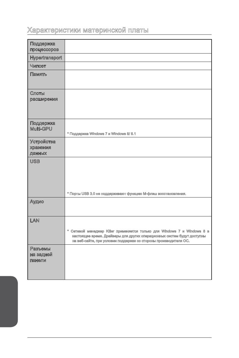
970 GAMING (MS-
970 GAMING
AMD
®
970 GAMING,
AMD
®
AM3/ AM3+.
Русский
Ru-2
®
FX
TM
/ Phenom
TM
II/ Athlon
TM
II
TM
Hypertransport
AMD
®
—
—
Multi-GPU
®
CrossFire
TM
*
®
SLI
TM
®
SB950
—
— RAID 10
USB
®
SB950
—
—
Realtek
®
ALC1150 Codec
—
—
LAN
—
Русский
Ru-3
1x 24-
1x 8-
USB 2.0)
1x 4-
2x 4-
2x 3-
1x
Hardware
ACPI 5.0, PnP 1.0a, SM BIOS 2.7, DMI 2.0
Military Class 4
Military Class Essentials
OC Genie 4
CLICK BIOS 4
AMD CrossFire
NVIDIA SLI
4K UHD Support
USB 3.0
Command Center
Fast Boot
Live Update 5
M-Flash
MSI
— Command Center
— Live Update 5
— Fast Boot
7-ZIP
Sound Blaster Cinema 2
Killer Network Manager
Norton Internet Security Solution
Русский
Ru-4
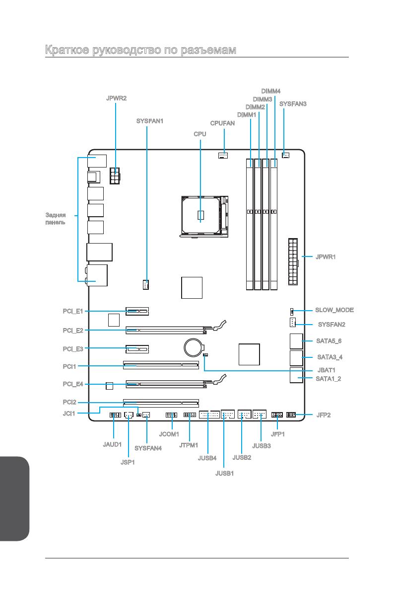
CPU
CPUFAN
DIMM2
JUSB3
JPWR1
SATA1_2
JAUD1
JUSB4
JTPM1
DIMM1
JPWR2
JCI1
SYSFAN1
JBAT1
SATA5_6
JUSB2
JFP1
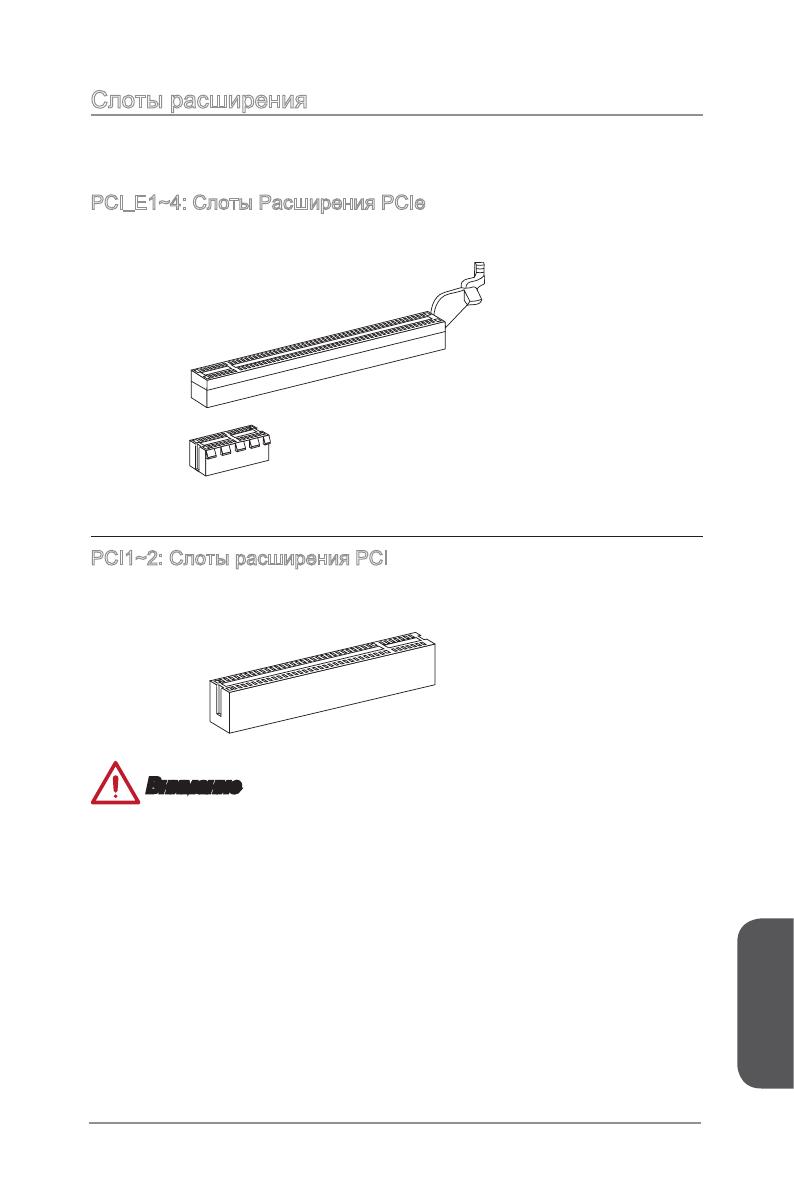
PCI_E1
PCI_E2
PCI_E3
PCI_E4
PCI1
JFP2
SYSFAN2
SYSFAN3
JUSB1
JCOM1
PCI2
SYSFAN4
SATA3_4
SLOW_MODE
DIMM3
DIMM4
JSP1
Русский
Ru-5
http://www.msi.com/cpu-support/
http://www.msi.com/test-report/
Русский
Ru-6
®
®
.
.
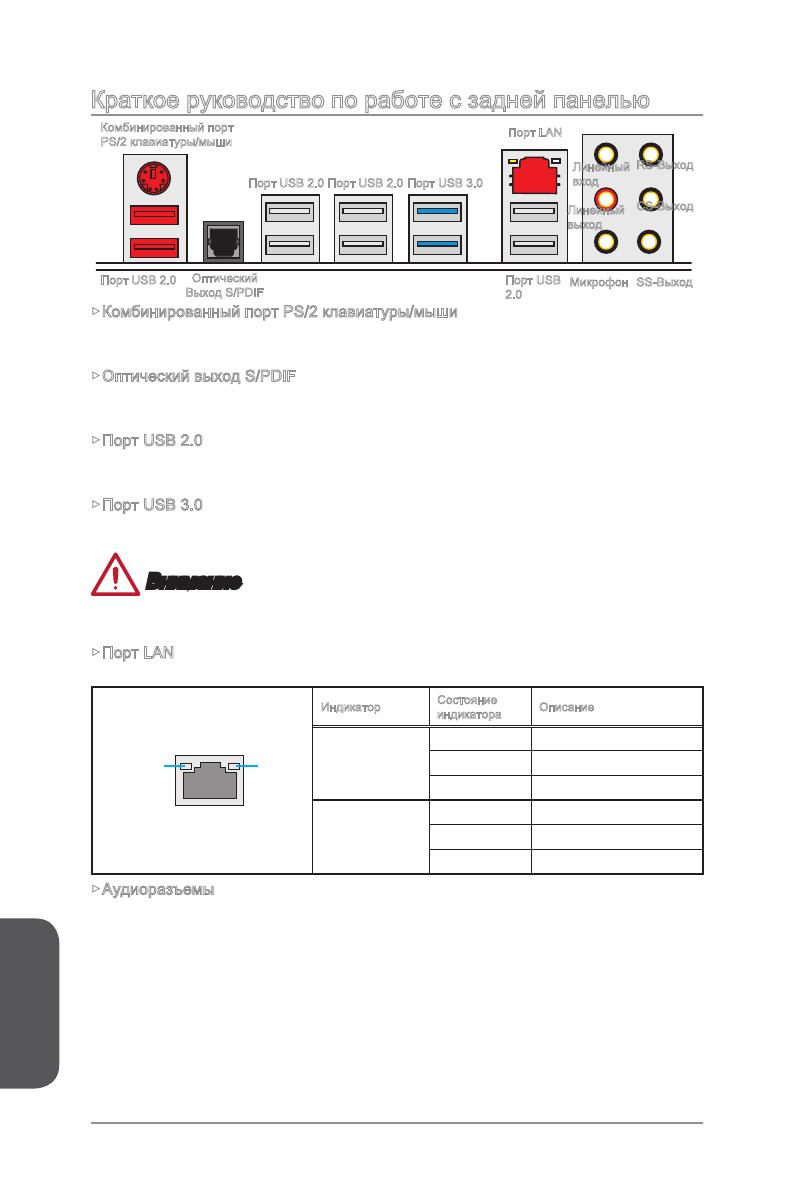
LINK/ACT
LED
SPEED
LED
Link/ Activity LED
Speed LED
—
7.1.
—
2.0
Русский
Ru-7
Русский
Ru-8
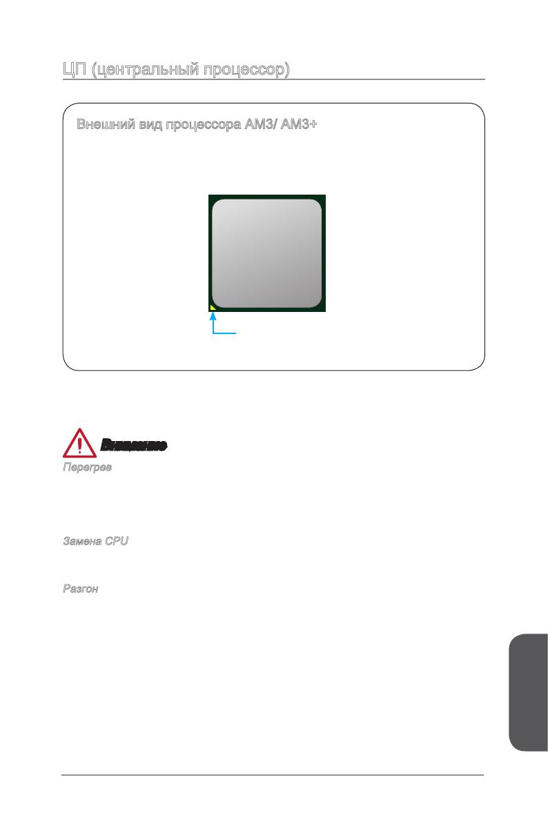
CPU,
Русский
Ru-9
CPU
Русский
Ru-10
DIMM1
DIMM2
DIMM3
DIMM4
DIMM1
DIMM3
DIMM1
DIMM2
DIMM3
DIMM4
Русский
Ru-11
Русский
Ru-12
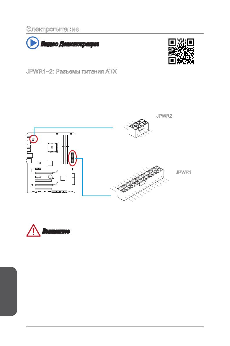
13.+3.3V
V
14.—12V
2.+3.3V
15.Ground
3.Ground
16.PS—ON#
4.+5V
17.Ground
5.Ground
18.Ground
6.+5V
19.Ground
7.Ground
22.+5V
10.+12V
20.Res
8.PWR OK
23.+5V
11. +12 V
21.+5V
9.5VSB
24.Ground
12.+3.3V
7.+12V
3.
Ground
Ground
8.+12V
.Ground
6.+12V
2.Ground
JPWR2
JPWR1
Русский
Ru-13
Русский
Ru-14
.
1.
.
2.
PCI_E2.
3.
.
4.
.
.
5.
.
Русский
Ru-15
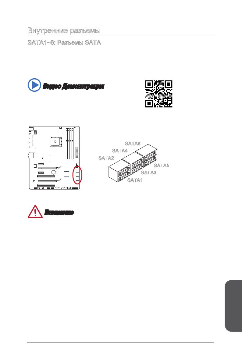
SATA .
SATA6
SATA5
SATA2
SATA1
SATA4
SATA3
.
Русский
Ru-16
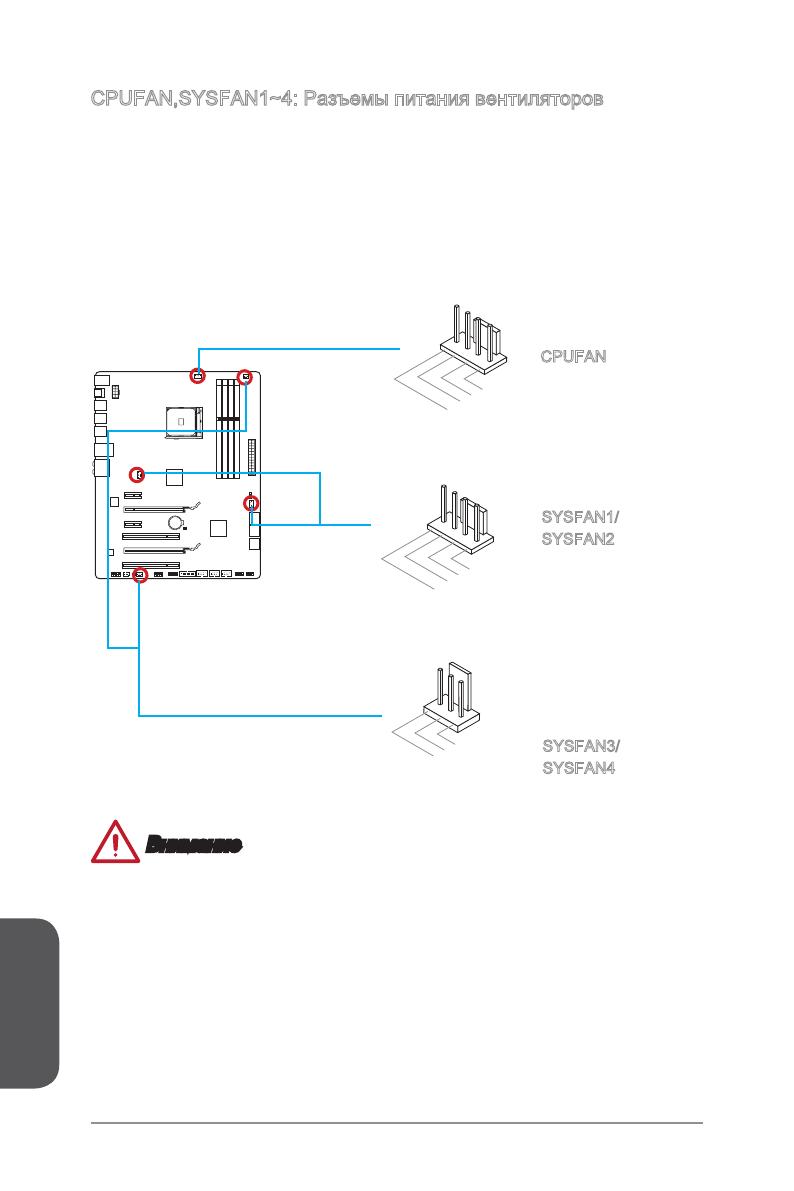
1.Ground
2.Speed Contro
3.Sense
4.NC
1.Ground
2.+12V
3.Sense
4.Speed Contro
CPUFAN
SYSFAN1/
SYSFAN2
1
.
G
r
o
u
n
2
.
+
1
2
V
3
.
N
o
U
s
SYSFAN3/
SYSFAN4
Русский
Ru-17
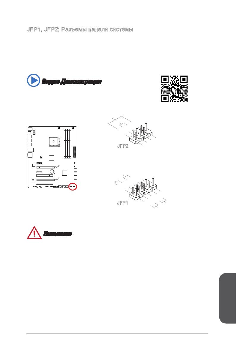
.
.
1.+
3.—
10.No Pin
5.—
Reset S
HDD LE
ower Switch
ower LED
7.+
9.Reserved
8.—
6.+
4.—
2.+
JFP1
1.Ground
3.Suspend LE
5.Power LE
7.No Pin
8.+
6.—
4.+
2.—
Buzzer
peaker
JFP2
.
.
Русский
Ru-18
.
N
C
8
.
G
r
o
u
n
d
6
.
U
S
B
1
+
4
.
U
S
B
1
—
.
V
C
C
1
.
V
C
C
3
.
U
S
B
0
—
5
.
U
S
B
0
+
7
.
G
r
o
u
n
d
9
.
N
o
P
i
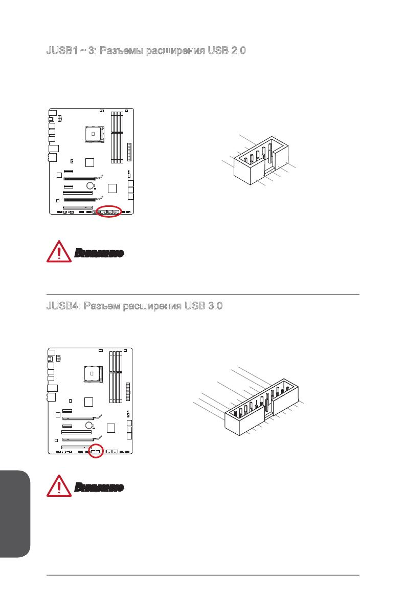
5.
USB3_TX_C_DN
4.Ground
3.USB3_RX_DP
2.USB3_RX_DN
1.Power
10.Ground
9. +USB2.0
8. —USB2.0
7.Ground
6.USB3_TX_C_DP
20.No Pin
19.Power
18.USB3_RX_DN
17.USB3_RX_DP
16.Ground
15.USB3_TX_C_DN
14.USB3_TX_C_DP
13.Ground
12.USB2.0 —
11. +
USB2.0
Page 1 — 970 GAMING
970 GAMINGMotherboardG52-76931XHPreface
Page 2
xPrefacePrefaceTÜRKÇE
Page 3
PrefacexiPrefacehttp://www.msi.com/html/popup/csr/cemm_
Page 4
xiiPrefacePreface CONTENTSChapter 1 Getting Started…1-1Packing Contents ..
Page 5
PrefacexiiiPrefaceChapter 2 Quick Installation …2-1CPU Installation …
Page 7
Chapter 1Getting StartedThank you for choosing the 970 GAMING Series (MS-7693 v4.X) ATX motherboard. The 970 GAMING Series motherboards are based on A
Page 8
Chapter 11-2Getting StartedPacking Contents* These pictures are for reference only and may vary without notice.* The packing contents may vary accordi
Page 9
Chapter 11-3Getting StartedAssembly Precautions The components included in this package are prone to damage from electrostatic discharge (ESD). Plea
Page 10 — ITALIANO
Chapter 11-4Getting StartedCPU Support Supports AMD® FXTM/ PhenomTM II/ AthlonTM II and SempronTM processors for the AM3/
Page 11 —
Chapter 11-5Getting StartedInternal Connectors 1x 24-pin ATX main power connector 1x 8-pin ATX 12V power connector 6x SATA 6Gb/s connectors 3x
Page 12
iiPrefacePrefaceCopyright NoticeThe material in this document is the intellectual property of MICRO-STAR INTERNATIONAL. We take every care in the pre
Page 13
Chapter 11-6Getting StartedSoftware Drivers MSI — Command Center — Live Update 5 — Fast Boot 7-ZIP Sound Blaster Cinema 2 Killer Network
Page 14
Chapter 11-7Getting StartedConnectors Quick GuideBack PanelCPU SocketCPUFANDIMM2JUSB3JPWR1SATA1_2JAUD1JUSB4JTPM1DIMM1JPWR2JCI1SYSFAN1JBAT1SATA5_6JUSB
Page 15
Chapter 11-8Getting StartedConnectors Reference GuidePort Name Port Type PageBack Panel I/O Ports 1-9CPU AM3/ AM3+ Socket 1-11CPUFAN,SYSFAN1~4
Page 16
Chapter 11-9Getting StartedBack Panel Quick Guide PS/2 Keyboard/ Mouse combo PortThe PS/2® keyboard/ mouse DIN connector for PS/2® keyboard/ mouse.
Page 17
Chapter 11-10Getting Started LAN PortThe standard RJ-45 LAN jack is for connecting to a Local Area Network (LAN). LINK/ACTLEDSPEEDLEDLED LED Status D
Page 18
Chapter 11-11Getting Started ImportantOverheatingOverheating can seriously damage the CPU and motherboard. Always make sure the cooling fans work prop
Page 19
Chapter 11-12Getting StartedWhen you are installing the CPU, make sure the CPU has a cooler attached on the top to prevent ov
Page 20
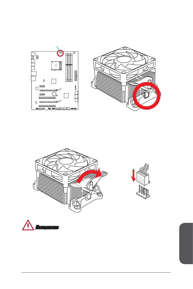
Chapter 11-13Getting Started5. Locate the CPU fan connector on the motherboard.6. Position the cooling set onto the retention mechanism. Hook one en
Page 21
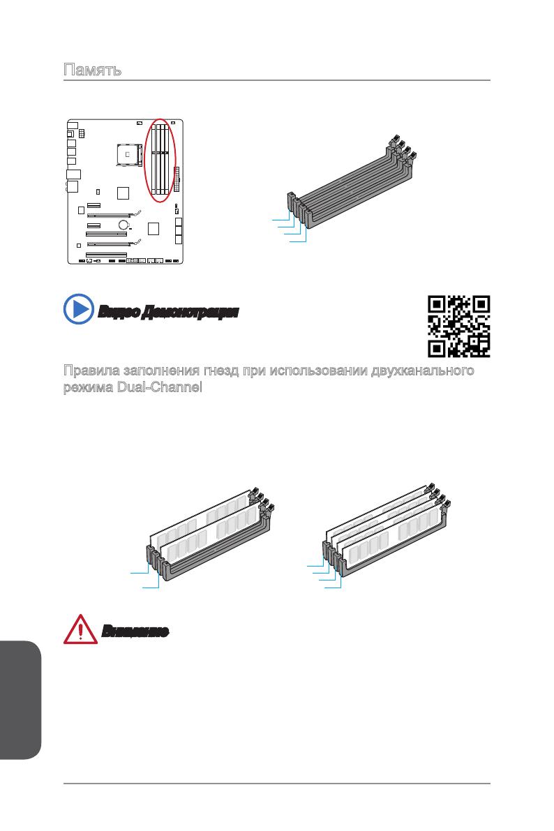
Chapter 11-14Getting StartedMemoryThese DIMM slots are used for installing memory modules. DIMM1DIMM2DIMM3DIMM4 Video DemonstrationWatch the video to
Page 22
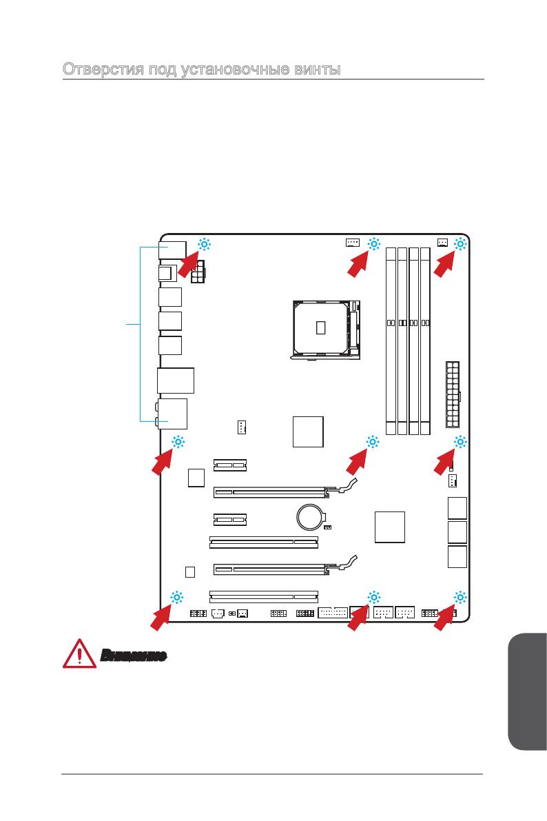
Chapter 11-15Getting StartedMounting Screw Holesfor an motherboar
Page 23
PrefaceiiiPrefaceSmartphone ApplicationMSI+ is a smart web gadget that works as a shopping navigator and provides specs comparison for IT buyers. With
Page 24
Chapter 11-16Getting StartedPower Supply Video DemonstrationWatch the video to learn how to install power supply connectors.http://youtu.be/gkDYyR_83I
Page 25
Chapter 11-17Getting StartedExpansion SlotsThis motherboard contains numerous slots for expansion cards, such as discrete graphics or audio cards.PCI_
Page 26
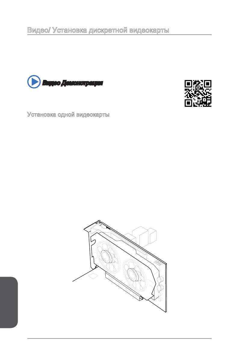
Chapter 11-18Getting StartedVideo/ Graphics Cards If available, this motherboard takes advantage of the CPU’s integrate graphics processor, but discre
Page 27
Chapter 11-19Getting StartedInternal ConnectorsSATA1~6: SATA Connectors This connector is a high-speed SATA interface port. Each connector can connect
Page 28
Chapter 11-20Getting StartedCPUFAN,SYSFAN1~4: Fan Power ConnectorsThe fan power connectors support system cooling fans with +12V. If the motherboard h
Page 29
Chapter 11-21Getting StartedJFP1, JFP2: System Panel ConnectorsThese connectors connect to the front panel switches and LEDs. When installing the fron
Page 30
Chapter 11-22Getting StartedThis connector is designed for connecting high-speed USB peripherals such as USB HDDs
Page 31
Chapter 11-23Getting StartedJCI1: Chassis Intrusion ConnectorThis connector connects to the chassis intrusion switch cable. If the computer case is op
Page 32
Chapter 11-24Getting StartedJCOM1: Serial Port ConnectorThis connector is a 16550A high speed communication port that sends/receives 16 bytes FIFOs. Y
Page 33
Chapter 11-25Getting StartedJumperJBAT1: Clear CMOS JumperThere is CMOS RAM onboard that is external powered from a battery located on the
Page 34
ivPrefacePrefaceSafety Instructions Always read the safety instructions carefully. Keep this User’s Manual for future reference. Keep this equi
Page 35
Chapter 11-26Getting StartedSwitch SLOW_MODE: Slow Mode Booting SwitchThis switch is used for LN2 cooling solution, that provides the extreme overcloc
Page 36
Chapter 11-27Getting StartedDrivers and Utilitiesperformance o
Page 38
Chapter 2Quick InstallationThis chapter provides demonstration diagrams about how to install your computer. Some of the installations also provide vid
Page 39
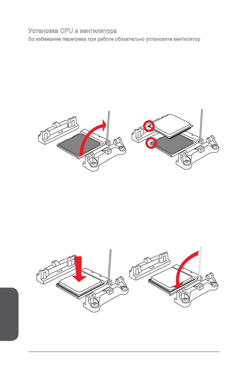
Chapter 22-2Quick InstallationCPU Installation1 23 45
Page 40
Chapter 22-3Quick Installation67
Page 41
Chapter 22-4Quick InstallationMemory Installation123http://youtu.be/76yLtJaKlCQ
Page 42
Chapter 22-5Quick InstallationMotherboard Installation12
Page 43
Chapter 22-6Quick Installation3
Page 44
Chapter 22-7Quick InstallationPower Connectors InstallationE68 8MSIMC4E68 8MSIMC4E68 8MSIMC4E68 8MSIMC4E68 8MSIMC4E68 8MSIMC4E68 8MSIMC4E68 8MSIMC4E68
Page 45
PrefacevPrefaceCE ConformityHereby, Micro-Star International CO., LTD declares that this device is in compliance with the essential safety requirement
Page 46
Chapter 22-8Quick InstallationE68 8MSIMC4E68 8MSIMC4E68 8MSIMC4E68 8MSIMC4E68 8MSIMC4E68 8MSIMC4E68 8MSIMC4E68 8MSIMC4E68 8MSIMC4E68 8MSIMC4E68 8MSIMC
Page 47
Chapter 22-9Quick InstallationSATA HDD Installation12http://youtu.be/RZsMpqxythcE688MSIMC4E688MSIMC4E688MSIMC4E688MSIMC4E688MSIMC4E688MSIMC4E688MSIMC4
Page 48
Chapter 22-10Quick InstallationE68 8MSIMC4E688MSIMC4E688MSIMC4E688MSIMC4E688MSIMC4E68 8MSIMC4E68 8MSIMC4E68 8MSIMC4E688MSIMC4E688MSIMC4E688MSIMC4E688M
Page 49
Chapter 22-11Quick InstallationE68 8MSIMC4E688MSIMC4E688MSIMC4E688MSIMC4E688MSIMC4E688MSIMC4E688MSIMC4E688MSIMC4E688MSIMC4E68 8MSIMC4USBE68 8MSIMC4E68
Page 50
Chapter 22-12Quick InstallationGraphics Card Installationhttp://youtu.be/mG0GZpr9w_A12
Page 51
Chapter 22-13Quick Installation345
Page 53
ImportantThe items under each BIOS category described in this chapter are under continuous update for better system performance. Therefore, the
Page 54
Chapter 33-2BIOS SetupEntering Setupconditions. You may need to run t
Page 55
Chapter 33-3BIOS SetupOverviewAfter entering BIOS, the following screen is displayed.BIOS menu selectionTemperature monitorSysteminformationBoot devic
Page 56
viPrefacePrefaceRadiation Exposure StatementThis equipment complies with FCC radiation exposure limits set forth for an uncontrolled environment. This
Page 57
Chapter 33-4BIOS Setup Virtual OC Genie ButtonEnables or disables the OC Genie function by clicking on this button. When enabled, this button will be
Page 58
Chapter 33-5BIOS SetupOperationYou can control BIOS settings with the mouse and the keyboard. The following table lists and describes the hot keys and
Page 59
Chapter 33-6BIOS SetupSETTINGSSystem Status System DateSets the system date. Use tab key to switch between date elements.The format is <day> &l
Page 60
Chapter 33-7BIOS SetupAdvanced PCI Subsystem SettingsSets PCI Express interface protocol and latency timer. Press <Enter> to enter the sub-menu
Page 61
Chapter 33-8BIOS Setup SATA Mode [AHCI Mode]Sets the operation mode of the onboard SATA controller. The default mode is AHCI.[Disabled] Disables the
Page 62
Chapter 33-9BIOS Setup Serial (COM) Port 0 Configurationmenu. Seri
Page 63
Chapter 33-10BIOS Setup ImportantIf you want to enter BIOS with enabled “MSI Fast Boot” mode or enabled «Fast Boot» mode, you have to click
Page 64
Chapter 33-11BIOS Setup Resume From S3/S4/S5 by PS/2 Keyboard [Disabled]Disables or enables the system wake up by PS/2 keyboard.[Any Key] Enables t
Page 65
Chapter 33-12BIOS Setup Press <Enter> to enter the sub-menu. Chassis Intrusion [Disabled]This function will be
Page 66
Chapter 33-13BIOS SetupOC ImportantOverclocking your PC manually is only recommended for advanced users.Overclocking is not guaranteed, and if don
Page 67
PrefaceviiPrefaceCalifornia, USA: The button cell battery may contain perchlorate material and requires special handling when recycled or disposed of
Page 68
Chapter 33-14BIOS Setup AMD Turbo Core Technology [Auto]Based on AMD Turbo Core Technology, part of CPU core ratio may pop down for providing more pe
Page 69
Chapter 33-15BIOS Setup HT Link SpeedThis item allows you to set the Hyper-Transport Link speed. Setting to [Auto], the system will detect the HT lin
Page 70
Chapter 33-16BIOS Setup AMD Cool’n’Quiet [Auto]Enabled or disabled AMD Cool’n’Quiet function. [Auto] Depends on AMD Design.[Enable] Enables AMD Co
Page 71
Chapter 33-17BIOS SetupM-FLASH Importantonly). Save BIOS to storage
Page 72
Chapter 33-18BIOS SetupOC PROFILE
Page 73
Chapter 33-19BIOS SetupHARDWARE MONITORSpeedgraphic displayCurrent informationFanVoltagedisplay
Page 74
Chapter 33-20BIOS SetupPlease follow the description below to set the temperatures and fan speeds.abcdef a — Selects a fan you want to specify the s
Page 75
Appendix ARealtek AudioThe Realtek audio provides 10-channel DAC that simultaneously supports 7.1 sound playback and 2 channels of independent stereo
Page 76
Appendix AA-2Realtek AudioAfter installing the audio driver (see Chapter 1 — Driver and Utilities), the “Realtek HD
Page 77
Appendix AA-3Realtek Audio Device SelectionHere you can select a audio output source to change the related options. The “check” sign indicates the de
Page 78
viiiPrefacePrefaceWEEE (Waste Electrical and Electronic Equipment) StatementENGLISHTo protect the global environment and as an environmentalist, MSI m
Page 79
Appendix AA-4Realtek AudioHardware Default SettingThe following diagrams are audio back panel default setting. Backpanel audio jacks to 2-channel spe
Page 80
Appendix AA-5Realtek Audio Backpanel audio jacks to 6-channel speakers diagramRearFrontCente r&Subwoo fer Backpanel audio jacks to 8-channel s
Page 82
Appendix BAMD RAID
Page 83
Appendix BB-2AMD RAIDCreating and deleting RAID set and performing other RAID setting up operations are done in the RAID BIOS. During
Page 84
Appendix BB-3AMD RAIDView Drives Assignments This window displays the model number, capacities and assignment of the drives physically attached to the
Page 85
Appendix BB-4AMD RAIDperformance,
Page 86
Appendix BB-5AMD RAID only. Gigabyte Boundary, allows use of sligh
Page 87
Appendix BB-6AMD RAID6. The message will show up on the bottom, press any key to use maximum capacity or press [Ctrl-Y] to modify array capacity manu
Page 88
Appendix BB-7AMD RAIDDelete LD Menu (Deleting RAID)1. Press “3” on the main to enter the Delete LD Menu.2. Choose a LD No. you want to delete and pr
Page 89
PrefaceixPrefaceESPAÑOLMSI como empresa comprometida con la protección del medio ambiente, recomienda:Bajo la directiva 2002/96/EC de la Unión Europea
Page 90
Appendix BB-8AMD RAID ImportantPlease follow the instruction below to make an “AMD® RAID Driver” for yourself.Insert the MSI Driver Disc into the op
Устройство:
MSi 970 GAMING
Производитель: MSi
Размер: 7,21 MB
Добавлено: 2023-05-15
Количество страниц: 90
Как пользоваться?
Наша цель — обеспечить Вам самый быстрый доступ к руководству по эксплуатации устройства MSi 970 GAMING. Пользуясь просмотром онлайн Вы можете быстро просмотреть содержание и перейти на страницу, на которой найдете решение своей проблемы с MSi 970 GAMING.
Для Вашего удобства
Если просмотр руководства MSi 970 GAMING непосредственно на этой странице для Вас неудобен, Вы можете воспользоваться двумя возможными решениями:
- Полноэкранный просмотр -, Чтобы удобно просматривать инструкцию (без скачивания на компьютер) Вы можете использовать режим полноэкранного просмотра. Чтобы запустить просмотр инструкции MSi 970 GAMING на полном экране, используйте кнопку Полный экран.
- Скачивание на компьютер — Вы можете также скачать инструкцию MSi 970 GAMING на свой компьютер и сохранить ее в своем архиве. Если ты все же не хотите занимать место на своем устройстве, Вы всегда можете скачать ее из ManualsBase.
MSi 970 GAMING Руководство пользователя — Online PDF
Ознакомьтесь с подробным руководством пользователя для замечательного творения MSi, модель 970 GAMING. Получите ценную информацию и инструкции, чтобы максимально использовать возможности вашего устройства и оптимизировать взаимодействие с пользователем. Раскройте весь потенциал своего устройства MSi 970 GAMING с помощью этого подробного руководства пользователя, в котором содержатся пошаговые инструкции и советы экспертов, которые сделают работу с ним легкой и приятной.
Печатная версия
Многие предпочитают читать документы не на экране, а в печатной версии. Опция распечатки инструкции также предусмотрена и Вы можете воспользоваться ею нажав на ссылку, находящуюся выше — Печатать инструкцию. Вам не обязательно печатать всю инструкцию MSi 970 GAMING а только некоторые страницы. Берегите бумагу.
Резюме
Ниже Вы найдете заявки которые находятся на очередных страницах инструкции для MSi 970 GAMING. Если Вы хотите быстро просмотреть содержимое страниц, которые находятся на очередных страницах инструкции, Вы воспользоваться ими.


