-
Contents
-
Table of Contents
-
Bookmarks
Quick Links
Related Manuals for Sonel MPI-525
Summary of Contents for Sonel MPI-525
-
Page 3: Operating Manual
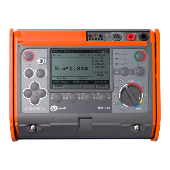
OPERATING MANUAL METER FOR ELECTRICAL INSTALATION PARAMETERS MPI-525 SONEL S. A. ul. Wokulskiego 11 58-100 Świdnica Version 2.4 20.01.2016…
-
Page 4
The MPI-525 meter is a modern, easy in use and safe measuring device. Please acquaint yourself with the present manual in order to avoid measuring errors and prevent possible problems related to operation of the meter. MPI-525 OPERATING MANUAL version 2.4… -
Page 5: Table Of Contents
3.6.2 Measurements with AutoISO-2500 adapter ……….34 …………. 36 VOLTAGE MEASUREMENT OF RESISTANCE 3.7.1 Measurement of resistance of protective conductors and equipotential bonding with ±200 mA current …………..36 3.7.2 Measurement of resistance …………….37 MPI-525 OPERATING MANUAL version 2.4…
-
Page 6
) ……63 10.2.5 Additional uncertainties according to IEC 61557-6 (RCD) ……64 EQUIPMENT ………………….64 11.1 ………………64 TANDARD QUIPMENT 11.2 ………………64 PTIONAL QUIPMENT POSITIONS OF THE METER’S COVER …………67 MANUFACTURER ………………..67 MPI-525 OPERATING MANUAL version 2.4… -
Page 7: Safety
The MPI-525 meter has been designed for the purpose of measurements of short-circuit loop im- pedance, earth connection and equipotential bonding resistance, RCDs parameters as well as in- sulation resistance measurements.
-
Page 8: Menu
2 Menu The Menu is accessible in each position of the rotary switch. Press MENU push-button. Select a proper item by means of push-buttons. Enter a selected option by pressing ENTER. Wireless transmission See chapter 5.3. MPI-525 OPERATING MANUAL version 2.4…
-
Page 9: Settings Of Measurements
The meter is designed for filtration of interferences that originate from 50 Hz and 60 Hz networks. By means of push-buttons se- lect a parameter to be changed, by means of select network voltage and frequency. Confirm a choice made by means of ENTER push-button. MPI-525 OPERATING MANUAL version 2.4…
-
Page 10: Additional Results In Insulation Resistance Measurement
ENTER push- button. 2.2.4 Measurement settings The setting enables activation/deactivation of the field displaying measurement settings. Show or hide the field with measurement settings by means of push-buttons, press ENTER push-button. MPI-525 OPERATING MANUAL version 2.4…
-
Page 11: Cell Autoincrementing
(automatic incre- menting is deactivated); confirm a choice made by means of ENTER push-button. Settings of the meter MPI-525 OPERATING MANUAL version 2.4…
-
Page 12: Lcd Contrast
User can turn the LCD backlight on at any time by pushing button. The LCD backlight setting defines the period, after which the backlight is automatically turned off. When “Always” option is cho- sen, to turn the backlight off user will need to push button again. MPI-525 OPERATING MANUAL version 2.4…
-
Page 13: Auto-Off Settings
This function may be used only by the users who are fluent in operation of com- puter equipment. The guarantee does not cover defective operation of the device resulting from wrong use of this function. MPI-525 OPERATING MANUAL version 2.4…
-
Page 14: Language Selection
Before updating the program, download the program that is use for programming the meter from the manufacturer’s website (www.sonel.pl), install this program on your computer and connect the meter to the computer. Select Software upgrade in the MENU and follow the instructions displayed by the program.
-
Page 15: Measurements
1 second. When voltage if found on PE, the device displays PE! message (error in the installation; PE lead is connected to the phase lead) and generates a continuous audio signal. MPI-525 OPERATING MANUAL version 2.4…
-
Page 16: Measurement Of Short Circuit Loop Parameters
3.3.1 Measurement of short circuit loop parameters in L-N and L-L circuit Set the rotary switch of function se- lection at Z position. L-N,L-L L-N,L-L MPI-525 OPERATING MANUAL version 2.4…
-
Page 17
— press F2 to select desired voltage and press ENTER. Connect test leads according to the drawing a) for measurement in L-N circuit or b) for measurement in L-L circuit The meter is ready for meas- urement. MPI-525 OPERATING MANUAL version 2.4… -
Page 18
Loop circuit mal- The meter should be serviced. function! No U Lack of U voltage before the principal measurement. Before measurement, voltage at test terminals exceeds U>500 V! and con- 500 V. tinuous audio signal MPI-525 OPERATING MANUAL version 2.4… -
Page 19: Measurement Of Short Circuit Loop Parameters In L-Pe Circuit
ENTER push-button. Connect test leads according to one of the drawings. Checking effectiveness of protection against electric shock of the device housing in case of: a) TN network b) TT network MPI-525 OPERATING MANUAL version 2.4…
-
Page 20: Measurement Of Short Circuit Loop Impedance In L-Pe Circuit Protected With Residual Current Device (Rcd)
L-N circuit or L-L circuit. 3.3.3 Measurement of short circuit loop impedance in L-PE circuit protected with residual current device (RCD) Set the rotary switch of function se- lection at Z RCD position. L-PE MPI-525 OPERATING MANUAL version 2.4…
-
Page 21: Prospective Short-Circuit Current
The meter always measures impedance Z . The short-circuit current is calculated according to the following formula: I where: Z — measured impedance, U — voltage that depends on settings of I button, according to the following Table: MPI-525 OPERATING MANUAL version 2.4…
-
Page 22: Measurement Of Resistance-To-Earth
Measurement of resistance-to-earth The three-pole measuring method is the basic type of resistance-to-earth measurement. Disconnect earth elec- trode being tested from the installation of the building. MPI-525 OPERATING MANUAL version 2.4…
-
Page 23
The earth electrode being tested and the current electrode and the voltage electrode should be located in one line. The meter is ready for measurement. Value of interference voltage U can be read on the display. Press F1 push-button to change test voltage. MPI-525 OPERATING MANUAL version 2.4… -
Page 24
In such a case, the ratio between resistance of the probes and resistance of the earth elec- MPI-525 OPERATING MANUAL version 2.4… -
Page 25: Measurement Of Rcd Parameters
0.4I regard- n less of the settings concerning waveform and multiplication factor I n 3.5.1 Measurement of RCD trip current Set the rotary switch of function selection at I position. MPI-525 OPERATING MANUAL version 2.4…
-
Page 26
U Press F2 push-button MODE and move to selection of measurement mode. Select an appropriate item by means of push-buttons and confirm by pressing ENTER. Connect the device to the installation according to the drawing. MPI-525 OPERATING MANUAL version 2.4… -
Page 27
Value of network volt- age and frequency can be read on the display. Press START to begin measurement. Read out the result. Remarks: — Measurement of t trip time for selective RCD is not available. MPI-525 OPERATING MANUAL version 2.4… -
Page 28: Measurement Of Rcd Trip Time
Move to selection of a second group of parameters by means of push-buttons. Press F1 push-button and move to selection of U Press F2 push-button and move to selection of RCD type. Press F3 push-button MODE and move to selection of measurement mode. MPI-525 OPERATING MANUAL version 2.4…
-
Page 29
Connect the device to the installation according to the drawing. The meter is ready for measurement. Value of network volt- age and frequency can be read on the display. Press START to begin measurement. Read out the result. MPI-525 OPERATING MANUAL version 2.4… -
Page 30: Automatic Measurement Of Rcd Parameters
Set the rotary switch of function selection at AUTO position. Press F1 push-button and move to I selection. n Press F2 push-button and move to selection of cur- rent waveform. Press F3 push-button and move to selection of RCD type. MPI-525 OPERATING MANUAL version 2.4…
-
Page 31
L lead length (at Z L-PE measurement). Select an appropriate item by means of push-buttons and confirm by pressing ENTER. Connect the device to the installation according to the drawing. MPI-525 OPERATING MANUAL version 2.4… -
Page 32
– total cycle; upper bar – measurement of Z RCD and I L-PE Read out the result. Groups of results displayed are changed by means of F3 and F4 push-buttons. MPI-525 OPERATING MANUAL version 2.4… -
Page 33: Measurement Of Insulation Resistance
U Press F2 TIME push- button and move to selec- tion of t and t periods. The “—“ value means that the period counting is disa- bled. MPI-525 OPERATING MANUAL version 2.4…
-
Page 34
At the end of the particular time period the current value of the insulation re- sistance (designated as R or R according to the time period that has expired) is displayed. Absorption coefficients are calculated as: MPI-525 OPERATING MANUAL version 2.4… -
Page 35
Remarks: During measurements of insulation resistance, dangerous voltage up to 2,5 kV present at the ends of test leads of MPI-525 meter. It is forbidden to disconnect test leads and to change the position of the func- tion switch before completion of measurement. Failure to obey the above in- struction will lead to high voltage electric shock and make it impossible to dis- charge the object tested. -
Page 36: Measurements With Autoiso-2500 Adapter
(3-, 4- or 5-cores lead). Select an appropriate item by means of push-buttons and confirm by pressing ENTER. Connect AutoISO-2500 adapter to the lead tested. MPI-525 OPERATING MANUAL version 2.4…
-
Page 37
— The difference between the measuring of leads and energetic cables is as follows: for the leads the insulation between all the pairs of cores is measured, for energetic cables – between each of cores and the others connected to each other and to the ground. MPI-525 OPERATING MANUAL version 2.4… -
Page 38: Low-Voltage Measurement Of Resistance
±200 mA Press F1 push-button and move to selection of measurement mode. ±200 mA item by means of Select R CONT push-buttons and confirm by press- ing ENTER. Connect the meter to the object tested. MPI-525 OPERATING MANUAL version 2.4…
-
Page 39: Measurement Of Resistance
3.7.2 Measurement of resistance Set the rotary switch of function selec- tion at R position. ±200 mA MPI-525 OPERATING MANUAL version 2.4…
-
Page 40
Press F1 push-button and move to selection of measurement mode. Select R position by means of push-buttons and confirm by pressing ENTER. Connect the meter to the object tested. MPI-525 OPERATING MANUAL version 2.4… -
Page 41: Calibration Of Test Leads
T eliminate the influence of the resistance of test leads on measurement result, the compensa- tion (autozeroing) of resistance should be performed. For this purpose, R and R functions ±200 mA have AUTOZERO sub-function. Press F2 push-button. Follow the instructions displayed on the screen. MPI-525 OPERATING MANUAL version 2.4…
-
Page 42: Checking Sequence Of Phases
To remove the AUTOZERO compensation (return to default cali- bration), perform the above-mentioned activities, but with test leads open in point 3. Checking sequence of phases Set the rotary switch of function selection position. MPI-525 OPERATING MANUAL version 2.4…
-
Page 43
Connect the meter to the installation according to the drawing. Phase-to-phase voltages. The arrow rotates clockwise: correct Signalling the sequence of phas- presence of individual phases. the arrow rotates counterclockwise: incorrect sequence of phases. MPI-525 OPERATING MANUAL version 2.4… -
Page 44: Memory Of Measurement Result Data
Memory of measurement result data MPI-525 meters are equipped with the memory that can store 50,000 single measurement results. The whole memory is divided into 10 memory banks containing 99 memory cells each. Thanks to dy- namic memory allocation, each of the memory cells can contain different quantity of single measure- ment results, depending on the needs.
-
Page 45
RCD that have been stored n previously will be lost. — Complete set of results (main result and supplementary results) for a given measuring function and preset measurement settings are stored in the memory. MPI-525 OPERATING MANUAL version 2.4… -
Page 46: Viewing Memory Data
Select memory bank by means of push-buttons; se- lect a memory cell by means of push-buttons; par- ticular results or components of the result are selected by means of F3 and F4 push-buttons. MPI-525 OPERATING MANUAL version 2.4…
-
Page 47
, [LIMIT I], [NOISE] CABLE 4: R (L1-N), (L2-N), , [LIMIT I], [NOISE] (L3-N), , [LIMIT I], [NOISE] CABLE 4: R (L1-L2), , [LIMIT I], [NOISE] (L1-L3), , [LIMIT I], [NOISE] (L2-L3), , [LIMIT I], [NOISE] MPI-525 OPERATING MANUAL version 2.4… -
Page 48: Deleting Memory Data
The same principle applies to memory banks. If the memory is stored in a non-continuously, empty measurements and memory banks are omitted during viewing. Deleting memory data Set the rotary switch of function selec- tion at MEM position. Select “Memory erasing” by means of push-buttons. MPI-525 OPERATING MANUAL version 2.4…
-
Page 49
Press ENTER push-button. Select deletion of the whole memory, a memory bank or a measurement by means of push-buttons. Follow the instruction displayed by the meter. MPI-525 OPERATING MANUAL version 2.4… -
Page 50: Data Transmission
USB cable and appropriate software. If the required accessories such have not been purchased along with the meter, then they are available from the manufacturer or an authorised distributor. The accessories may be used with many devices manufactured by SONEL S.A. equipped with the USB interface.
-
Page 51
The following messages will be displayed: Connecting and then Connection active. If it is im- possible to establish connection the message Wireless connection lost will appear. Once the con- nection is established, follow the programme manual for data filing. Note: Standard pin for OR-1 is the „123”. MPI-525 OPERATING MANUAL version 2.4… -
Page 52: Power Supply
Replacement of batteries (accumulators) MPI-525 meter is powered by 4 batteries (LR14). It can be also powered by the manufacturer’s accumulator package (SONEL NiMH). Battery charger is installed inside the meter and cooperates only with the manufacturer’s accumu- lator package.
-
Page 53: Charging Of Accumulators
Charging finished. In order to turn the device off, remove the power supply plug of the charger. Operating mode Messages regarding the process of charging Charging progress, the changing interior section symbolizes charging MPI-525 OPERATING MANUAL version 2.4…
-
Page 54: General Principles Regarding Using Ni-Mh Accumulators
(2-3 charge and discharge cycles). The most important factor which influences the lifetime of an accumulator is the depth of discharge. The deeper the discharge of the accumulator, the shorter its lifetime. MPI-525 OPERATING MANUAL version 2.4…
-
Page 55
— Do not charge or use accumulators in extreme temperatures. Extreme temperatures reduce the life- time of batteries and accumulators. Avoid placing devices powered from accumulators in very hot en- vironments. The nominal working temperature must be absolutely observed. MPI-525 OPERATING MANUAL version 2.4… -
Page 56: Cleaning And Maintenance
Worn-out electronic equipment should be sent to a collection point in accordance with the law of worn-out electric and electronic equipment. Before the equipment is sent to a collection point, do not dismantle any elements. Observe the local regulations concerning disposal of packages, worn-out batteries and accumula- tors. MPI-525 OPERATING MANUAL version 2.4…
-
Page 57: Technical Data
Indications of short circuit loop resistance R and short circuit loop reactance X Display range Resolution Basic uncertainty 0..19.99 0.01 (5% + 5 digits) of Z value <20 Calculated and displayed for a value of Z MPI-525 OPERATING MANUAL version 2.4…
-
Page 58
(which is used for displaying). As the correct value, consider I current value, displayed by the meter or by firmware. MPI-525 OPERATING MANUAL version 2.4… -
Page 59
1000 1000 * — does not apply to U = 110 V, 115 V and 127 V MPI-525 OPERATING MANUAL version 2.4… -
Page 60
10 % I n 300 mA 105..420 mA 1 mA n 500 mA 175..700 mA measurement can be performed for positive or negative half-periods of residual current test current pass time …….. max. 3200 ms MPI-525 OPERATING MANUAL version 2.4… -
Page 61
Measurement of continuity of protective conductors and equipotential bondings with 200 mA current Test range according to IEC 61557-4: 0,12…400 Range Resolution Basic uncertainty 0.00…19.99 0.01 20.0…199.9 0.1 (2% w.m. + 3 digits) 200…400 1 MPI-525 OPERATING MANUAL version 2.4… -
Page 62
= 500 V 0…1999 k 1 k 2.00…19.99 M 0.01 M (3 % w.m. + 8 digits) 20.0…199.9 M 0.1 M 200…999 M 1 M (4 % w.m. + 6 digits) 1.00…2.00 G 0.01 G MPI-525 OPERATING MANUAL version 2.4… -
Page 63
EN 60529 …………… IP54 d) power supply of the meter ……………………..alkaline batteries 4×1,5 V LR14 (C) or accumulator package SONEL NiMH 4,8 V 4,2 Ah e) parameters of AC adapter for the battery charge ……100 V…240 V, 50 Hz…60 Hz dimensions ………………….. -
Page 64: Additional Data
Frequency 99%..101% Network voltage 85%..110% Harmonic DC component 10.2.3 Additional uncertainties according to IEC 61557-4 (R ±200 mA) Significant parameter Designation Additional uncertainty Position Supply voltage 0.5% (BAT is not lit) Temperature 0…35°C 1.5% MPI-525 OPERATING MANUAL version 2.4…
-
Page 65: Additional Uncertainties According To Iec 61557-5
≥ 5 k Current electrode resistance Resistance to earth Current electrode resistance Resistance to earth Resistance of voltage electrode Rs[Ω] MPI-525 OPERATING MANUAL version 2.4…
-
Page 66: Additional Uncertainties According To Iec 61557-6 (Rcd)
SONEL CD accumulator package NiMH 4.8V 4.2Ah – WAAKU07 11.2 Optional Equipment Additionally, the following items that are not included in the scope of standard equipment can be purchased from the manufacturer or the distributors: MPI-525 OPERATING MANUAL version 2.4…
-
Page 67
WAADAAGT16C – four-wire version triple phase socket adapter AGT-16P WAADAAGT63P – five-wire version adapter AutoISO-2500 WAADAAGT32P – five-wire version WAADAAGT32C – four-wire version triple phase socket adapter AGT-63P triple phase socket adapter AGT-32P MPI-525 OPERATING MANUAL version 2.4… -
Page 68
LSWPLMPI525 calibration certificate software for creating measurement pro- tocols „SONEL Pomiary Elektryczne” (SONEL Electrical measurements) Note The software is supported by the following systems: Windows XP (Service Pack 2), Windows Vista, Windows 7. MPI-525 OPERATING MANUAL version 2.4… -
Page 69: Positions Of The Meter’s Cover
SONEL S.A. ul. Wokulskiego 11 58-100 Świdnica Poland tel. +48 74 858 38 60 fax +48 74 858 38 09 E-mail: export@sonel.pl Web page: www.sonel.pl Attention: Service repairs must be realised solely by the manufacturer. MPI-525 OPERATING MANUAL version 2.4…
-
Page 70
MPI-525 OPERATING MANUAL version 2.4…
Купить в 1 клик
- Наличие
- уточняйте
- Гарантия
- 12
- Самовывоз
-
Тюмень
- Возможна доставка до адреса
-
Способы оплаты
Описание
Характеристики
Комплектация
Стандартная комплектация:
| Количество | Индекс | |
|---|---|---|
| Адаптер WS-03 с сетевой вилкой UNI-SCHUKO и кнопкой «СТАРТ» | 1 | WAADAWS03 |
| Адаптер автомобильный (12В) | 1 | WAPRZLAD12SAM |
| Аккумуляторная батарея NiMH SONEL-07 4,8V | 1 | WAAKU07 |
| Зажим «Крокодил» изолированный жёлтый K02 | 1 | WAKROYE20K02 |
| Зажим «Крокодил» изолированный красный K02 | 1 | WAKRORE20K02 |
| Зажим «Крокодил» изолированный красный К09 11 кВ | 1 | WAKRORE32K09 |
| Зажим «Крокодил» изолированный черный К09 11 кВ | 1 | WAKROBL32K09 |
| Зарядное устройство для аккумуляторов Z7, модель SYS1319-3012 | 1 | WAZASZ7 |
| Зонд измерительный для забивки в грунт 30 см | 2 | WASONG30 |
| Зонд острый с разъёмом «банан» голубой | 1 | WASONBUOGB1 |
| Зонд острый с разъёмом «банан» красный | 1 | WASONREOGB1 |
| Зонд острый с разъемом «банан» желтый | 1 | WASONYEOGB1 |
| Зонд острый с разъемом «банан» красный 5кВ | 1 | WASONREOGB2 |
| Кабель последовательного интерфейса USB | 1 | WAPRZUSB |
| Комплект ремней «Свободные руки» | 1 | WAPOZSZEKRU |
| Провод измерительный 1,2 м с разъемами «банан» голубой | 1 | WAPRZ1X2BUBB |
| Провод измерительный 1,2 м с разъемами «банан» желтый | 1 | WAPRZ1X2YEBB |
| Провод измерительный 1,2 м с разъемами «банан» красный | 1 | WAPRZ1X2REBB |
| Провод измерительный 1,8 м с разъемами «банан» 5 кВ красный | 1 | WAPRZ1X8REBB |
| Провод измерительный 1,8 м экранированный с разъемами «банан» 5 кВ черный | 1 | WAPRZ1X8BLBB |
| Провод измерительный 25 м на катушке с разъемами «банан» красный | 1 | WAPRZ025REBBSZ |
| Провод измерительный 50 м на катушке с разъемами «банан» желтый | 1 | WAPRZ050YEBBSZ |
| Футляр L2 | 1 | WAFUTL2 |
Дополнительная комплектация:
| Индекс | |
|---|---|
| Адаптер AGT-16C | WAADAAGT16C |
| Адаптер AGT-16T | WAADAAGT16T |
| Адаптер AGT-32P | WAADAAGT32P |
| Адаптер AGT-32T | WAADAAGT32T |
| Адаптер AGT-63P | WAADAAGT63P |
| Адаптер AGT-16P | WAADAAGT16P |
| Адаптер AGT-32C | WAADAAGT32C |
| Адаптер AutoISO-2500 | WAADAAISO25 |
| Адаптер для тестирования устройств защитного отключения (УЗО) TWR-1J | WAADATWR1J |
| Аккумуляторная батарея NiMH SONEL-07 4,8V | WAAKU07 |
| Беспроводной интерфейс OR-1 (USB) | WAADAUSBOR1 |
| Зажим «Крокодил» изолированный голубой K02 | WAKROBU20K02 |
| Зажим «Крокодил» изолированный желтый К09 11 кВ | WAKROYE32K09 |
| Зонд измерительный для забивки в грунт 80 см | WASONG80 |
| Зонд острый с разъемом «банан» складной SP-2M | WASONSP2M |
| Отсек для батареек LR14 | WAPOJ1 |
| Провод измерительный 10 м с разъемами «банан» красный | WAPRZ010REBB |
| Провод измерительный 20 м с разъемами «банан» красный | WAPRZ020REBB |
| Провод измерительный 25 м на катушке с разъёмами «банан» голубой | WAPRZ025BUBBSZ |
| Провод измерительный 5 м с разъемами «банан» красный | WAPRZ005REBB |
| Провод измерительный 50 м на катушке с разъемами «банан» желтый | WAPRZ050YEBBSZ |
| Программа автоматического формирования протоколов испытаний электроустановок «СОНЭЛ Протоколы 2.0» | # |
| Футляр для двух зондов 80 см | WAFUTL3 |
Файлы

Оформить заказ
Экспертные мнения
Экспертные мнения
Купить MPI-525 Измеритель параметров электробезопасности электроустановок в Тюмени легко — просто позвоните по телефону:: 8-800-551-11-01
Sonel MPI-525 Measuring Instruments PDF User Guides and Manuals for Free Download: Found (2) Manuals for Sonel MPI-525 Device Model (Operation & User’s Manual, Operating Manual)
More Measuring Instruments Device Models:
-
janitza
UMG 96S 24V
Universal Measuring DeviceUMG 96S 24VOperating instructionsBrief instructions see last pageDoc No. 1.028.044.4Art. Nr. 33.03.081Janitza electronics GmbHVor dem Polstück 6D-35633 LahnauSupport Tel. 0049 6441 9642-22Fax 0049 6441 9642-30e-mail: [email protected]: http://www.janitza.comwww.janitza.comMin value,LT …
UMG 96S 24V Measuring Instruments, 96
-
Spectrum
6110FS
28 12360 S Industrial Dr. East Plainfield, IL 60585 (800) 248-8873 or (815) 436-4440 FAX: (815) 436-4460 E-Mail: [email protected] www.specmeters.com Technologies, Inc. Spectrum Catalog # 6110FS User’s manual SC 900 Soil Compaction Meter Technologies, Inc. Spectrum …
6110FS Measuring Instruments, 14
-
Agilent Technologies
E4402B
Agilent ESA-E SeriesSpectrum AnalyzerConfi guration GuideThis ESA configuration guide will help you determine which performance options, measurement personali-ties, accessories, and services to include in your new ESA-E, or to add as upgrades to an existing ESA-E. Options for the new EXA signal analyzer are shown alo …
E4402B Measuring Instruments, 12
-
LI-COR
LI-6800
LI-6800 6×6 cm Leaf ChamberThe 6×6 cm Leaf Chamber is for large leaves. This doc-ument provides installaion instructions for the large leafchamber. If the leaf fills less than half the chamber, werecommend using the 3×3 cm chamber instead.Detach the chamber from the headSix screws will be removed to detach a chamber …
LI-6800 Industrial Equipment, 2
Recommended Documentation:
MPI-525 – многофункциональный измерительный прибор. Прибор совмещает в себе функциональные возможности серии MZC, MRP, MIC, TKF и MRU. По сути MPI-525 – это электролаборатория в одном приборе. Расширенная стандартная комплектация включает все необходимое для качественного проведения работ в соответствии с нормативной документацией.
Функциональные возможности Sonel MPI-525:
- измерение в цепях «фаза-нуль», «фаза-защитный проводник», «фаза-фаза»;
- измерение в цепи «фаза-защитный проводник» без срабатывания УЗО;
- вычисление ожидаемого тока короткого замыкания;
- измерение параметров устройств защитного отключения (УЗО) типа АС, А и B;
- измерение параметров УЗО общего типа, с выдержкой времени срабатывания (тип G) и селективных (тип S) с номинальными дифференциальными токами 10, 30, 100, 300, 500 и 1000 мА;
- измерение времени отключения УЗО при токах 0.5, 1, 2 и 5-ти кратных номинальному дифференциальному току;
- автоматический режим измерения параметров УЗО;
- измерение напряжения прикосновения относительно номинального дифференциального тока УЗО;
- измерение сопротивления контактных соединений заземляющих, защитных проводников и проводников системы уравнивания потенциалов Rcont током ±200 мА разрешением 0,01 Ом;
- измерение сопротивления заземляющих устройств по трёхполюсной схеме (3p);
- измерение напряжения помех;
- измерение сопротивления измерительных зондов;
- автоматический расчет дополнительной погрешности, вызванной сопротивлением измерительных зондов;
- измерение сопротивления изоляции напряжением до 2500 В: стандартные величины 50 В, 100 В, 250 В, 500 В, 1000 В, 2500 В;
- измерение сопротивления изоляции до 10 ГОм;
- измерение сопротивления изоляции с использованием адаптеров AutoISO-2500;
- проверка последовательности чередования фаз;
- измерение напряжения переменного тока до 500 В;
- сохранение результатов измерений в память;
- передача данных на ПК по USB или с использованием беспроводного интерфейса OR-1;
- совместим с ПО Sonel Reader и СОНЭЛ Протоколы 2.0.
Назначение прибора MPI-525
Многофункциональный измеритель параметров электробезопасности электроустановок MPI-525 предназначен для измерения:
- параметров петли короткого замыкания
- тестирования параметров УЗО
- измерения сопротивления изоляции
- измерения переходных сопротивлений контактов и проводников постоянным током
- измерения сопротивления заземляющих устройств
- измерения действующего значения переменного тока
- контроля последовательности чередования фаз и перекоса фаз по напряжению
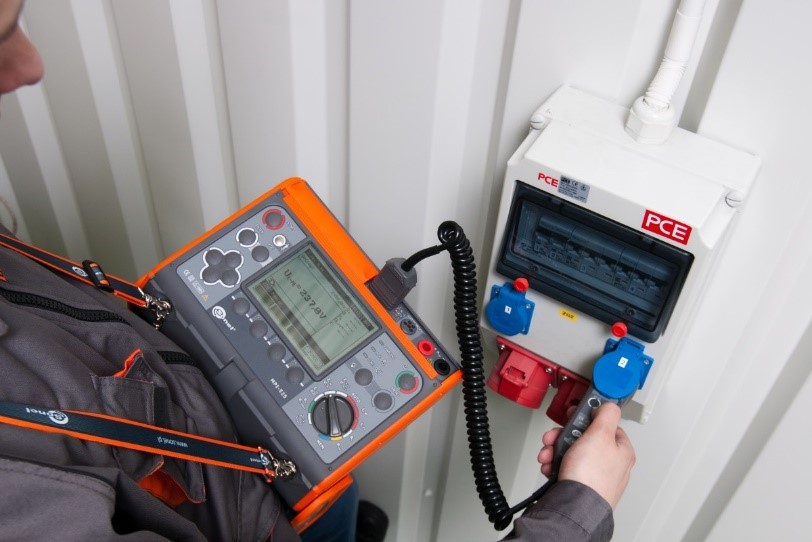
Проведение замеров с помощью MPI-525 |
Прибор применяется при наладке и эксплуатационном контроле состояния сети электропитания, а также при приемо-сдаточных и сертификационных испытаниях электроустановок зданий. |
1 Safety …………………………………………………………………………………………………. 5
2 Menu …………………………………………………………………………………………………… 6
2.1 Wireless transmission …………………………………………………………………………………. 6
2.2 Settings of measurements ……………………………………………………………………………. 6
2.2.1
Network voltage and frequency ………………………………………………………………………….. 7
2.2.2
2.2.3
2.2.4
Measurement settings ………………………………………………………………………………………. 8
2.2.5
Cell autoincrementing ………………………………………………………………………………………. 8
2.3 Settings of the meter …………………………………………………………………………………… 9
2.3.1
LCD contrast …………………………………………………………………………………………………… 9
2.3.2
LCD backlight time …………………………………………………………………………………………. 10
2.3.3
Auto-OFF settings ………………………………………………………………………………………….. 10
2.3.4
Date and time ……………………………………………………………………………………………….. 10
2.3.5
Factory (default) settings …………………………………………………………………………………. 11
2.3.6
Program update …………………………………………………………………………………………….. 11
2.4 Language selection …………………………………………………………………………………… 11
3 Measurements …………………………………………………………………………………… 12
3.3.1
3.3.2
3.3.3
current device (RCD) ……………………………………………………………………………………… 18
3.3.4
3.5.1
3.5.2
Measurement of RCD trip time …………………………………………………………………………. 25
3.5.3
3.6.1
Double-lead measurement ………………………………………………………………………………. 31
3.6.2
3.7.1
±200 mA current ……………………………………………………………………………………………. 36
3.7.2
Measurement of resistance ……………………………………………………………………………… 38
3.7.3
Calibration of test leads …………………………………………………………………………………… 39
4.2 Viewing memory data ………………………………………………………………………………… 44
4.3 Deleting memory data ……………………………………………………………………………….. 46
5 Data transmission ……………………………………………………………………………… 48
CONTENTS
MPI-525 — USER MANUAL
3