-
Contents
-
Table of Contents
-
Bookmarks
Quick Links
Related Manuals for Sonel MPI-520
Summary of Contents for Sonel MPI-520
-
Page 3: Operating Manual
OPERATING MANUAL METER FOR ELECTRICAL INSTALLATION PARAMETERS MPI-520 SONEL S. A. ul. Wokulskiego 11 58-100 Świdnica Version 3.4 23.09.2014…
-
Page 4
The MPI-520 meter is a modern, easy and safe in use measuring device. Please acquaint yourself with the present manual in order to avoid measuring errors and prevent possible problems related to operation of the meter. MPI-520 OPERATING MANUAL version 3.4… -
Page 5: Table Of Contents
EASUREMENT OF INSULATION RESISTANCE 3.7.1 Double-lead measurement …………….30 3.7.2 Measurements with AutoISO-1000c adapter ……….33 3.7.3 Measurements by means of leads with UNI-Schuko outlet plug (WS-03 and WS-04) ………………….34 …………. 36 VOLTAGE MEASUREMENT OF RESISTANCE MPI-520 OPERATING MANUAL version 3.4…
-
Page 6
) ……63 10.2.5 Additional uncertainties according to IEC 61557-6 (RCD) ……64 EQUIPMENT ………………….65 11.1 ………………65 TANDARD QUIPMENT 11.2 ………………65 PTIONAL QUIPMENT POSITIONS OF THE METER’S COVER …………66 MANUFACTURER ………………..66 MPI-520 OPERATING MANUAL version 3.4… -
Page 7: Safety
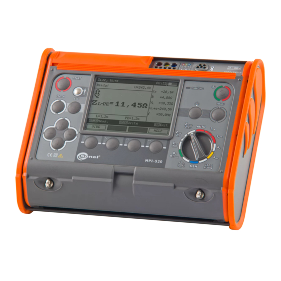
The MPI-520 meter has been designed for the purpose of measurements of earth connection and equipotential bonding, ground resistivity, as well as clamps current measurements. Any applica- tion that differs from those specified in the present manual may result in a damage to the device and constitute a source of danger for the user.
-
Page 8: Menu
2 Menu The Menu is accessible in each position of the rotary switch. Press MENU push-button. Select a proper item by means of push-buttons. Enter a selected option by pressing ENTER. Wireless transmission See chapter 5.3. MPI-520 OPERATING MANUAL version 3.4…
-
Page 9: Settings Of Measurements
The meter is designed for filtration of interferences that originate from 50 Hz and 60 Hz networks. By means of push-buttons se- lect a parameter to be changed, by means of select network voltage and frequency. Confirm a choice made by means of ENTER push-button. MPI-520 OPERATING MANUAL version 3.4…
-
Page 10: Main Result Of Short Circuit Loop Impedance Measurement
ENTER push- button. 2.2.3 Measurement settings The setting enables activation/deactivation of the field displaying measurement settings. Show or hide the field with measurement settings by means of push-buttons, press ENTER push- button. 2.2.4 Cell autoincrementing MPI-520 OPERATING MANUAL version 3.4…
-
Page 11: Settings Of The Meter
Select a suitable item by means of push-buttons; enter the edi- tion of a selected option by means of ENTER push-button. 2.3.1 LCD contrast Select contrast value by means of push-buttons; confirm a choice made by means of ENTER push-button. MPI-520 OPERATING MANUAL version 3.4…
-
Page 12: Lcd Backlight
2.3.4 Date and time By means of push-buttons select the value to be changed (day, month, year, hour, minute). Set a required value by means of push-buttons. When required settings are made, press ENTER push-button. MPI-520 OPERATING MANUAL version 3.4…
-
Page 13: Factory (Default) Settings
Before updating the program, download the program that is use for programming the meter from the manufacturer’s website (www.sonel.pl), install this program on your computer and connect the meter to the computer. Select Software upgrade in the MENU and follow the instructions displayed by the program.
-
Page 14: Measurements
When the meter is connected according to the drawing, touch the touch electrode with a finger and wait for about 1 second. When voltage if found on PE, the device displays PE! message (error in MPI-520 OPERATING MANUAL version 3.4…
-
Page 15: Measurement Of Current, Active Power, Reactive Power, Apparent Power And Cosφ Coefficient
Press F1 push-button. Select “U,I,f,cos,P,Q,S” by means push-buttons and press ENTER push- button. (If you want to meas- ure voltage or current only, select a proper position.) Assemble the system according to the below drawing. MPI-520 OPERATING MANUAL version 3.4…
-
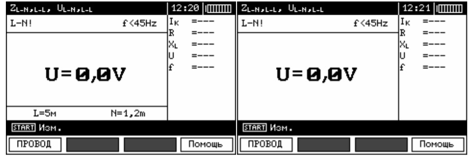
Page 16: Measurement Of Short Circuit Loop Parameters
L needs to be select- Select lead length by means push-buttons and press ENTER push- button. Connect test leads according to the drawing a) for measurement in L-N circuit or b) for measurement in L-L circuit MPI-520 OPERATING MANUAL version 3.4…
-
Page 17
— Minimum interval between successive measurements is 5 seconds. This minimum interval require- ment is controlled by the meter. A next measurement can be made only when READY! message ap- pears on the screen. MPI-520 OPERATING MANUAL version 3.4… -
Page 18: Measurement Of Short Circuit Loop Parameters In L-Pe Circuit
L-PE Press F1 push-button if L lead length needs to be se- lected. Select a lead length by means of push- buttons and press ENTER push-button. Connect test leads according to one of the drawings. MPI-520 OPERATING MANUAL version 3.4…
-
Page 19
— Double lead measurement is possible when a test lead other that the lead with a mains socket is se- lected. — Remaining issues connected with the measurements as well as the messages displayed are the same as those described for measurements in L-N circuit or L-L circuit. MPI-520 OPERATING MANUAL version 3.4… -
Page 20: Measurement Of Short Circuit Loop Impedance In L-Pe Circuit Protected With Residual Current Device (Rcd)
RCD. In such a sit- uation, one should try to reduce leakage current of the network being tested (for example, by discon- necting load points). MPI-520 OPERATING MANUAL version 3.4…
-
Page 21: Prospective Short-Circuit Current
U =220V U [V] U =230V 216 240 415 440 U [V] U =240V U voltage ranges for which short- voltage ranges for which short- circuit current value is calculated circuit current value is calculated MPI-520 OPERATING MANUAL version 3.4…
-
Page 22: Measurement Of Resistance-To-Earth
The earth electrode being tested and the current electrode and the voltage electrode should be located in one line. The meter is ready for measurement. Value of interference voltage U can be read on the display. Press F1 push-button to change test voltage. MPI-520 OPERATING MANUAL version 3.4…
-
Page 23
If R measurement results differ from one another by more than 3%, the distance of the current electrode from the earth electrode being tested should be consider- ably increased and the measurements should be repeat- MPI-520 OPERATING MANUAL version 3.4… -
Page 24: Measurement Of Rcd Parameters
Measurement has been interrupted with ESC key button. 3.6 Measurement of RCD parameters Attention: Measurement of U is always conducted with the use of sinusoidal current 0.4I n regardless of the settings concerning waveform and multiplication factor I n MPI-520 OPERATING MANUAL version 3.4…
-
Page 25: Measurement Of Rcd Disconnection Current
ENTER. Move to selection of a second group of parameters by means of push-buttons. Press F1 push-button and move to selection of U Press F2 MODE push-button and move to selection of measurement mode. MPI-520 OPERATING MANUAL version 3.4…
-
Page 26
Connect the device to the installation according to the drawing. The meter is ready for measurement. Value of network volt- age and frequency can be read on the display. Press START to begin measurement. Read out the result. MPI-520 OPERATING MANUAL version 3.4… -
Page 27: Measurement Of Rcd Disconnection Time
Select an appropriate item by means of push-buttons and confirm by pressing ENTER. Move to selection of a second group of parameters by means of push-buttons. MPI-520 OPERATING MANUAL version 3.4…
-
Page 28
Connect the device to the installation according to the draw- ing. The meter is ready for measurement. Value of network volt- age and frequency can be read on the display. Press START to begin measurement. MPI-520 OPERATING MANUAL version 3.4… -
Page 29: Automatic Measurement Of Rcd Parameters
n negative n positive n negative n positive n 10.* negative n 11.* positive 12.* negative * points in which an efficient RCD should disconnected Set the rotary switch of function selection at AUTO position. MPI-520 OPERATING MANUAL version 3.4…
-
Page 30
L lead length (at Z L-PE measurement). Select an appropriate item by means of push-buttons and confirm by pressing ENTER. Connect the device to the installation according to the drawing. MPI-520 OPERATING MANUAL version 3.4… -
Page 31
– total cycle; upper bar – measurement of Z RCD and I L-PE Read out the result. Groups of results displayed are changed by means of F3 and F4 push-buttons. MPI-520 OPERATING MANUAL version 3.4… -
Page 32: Measurement Of Insulation Resistance
R position. Press F1 push-button and move to selection of test voltage U Select an appropriate item by means of push-buttons and confirm by pressing ENTER. Connect test leads according to the drawing. MPI-520 OPERATING MANUAL version 3.4…
-
Page 33
ENTER push- button while holding START push- button in the pressed position. In order to interrupt the mesaurement, press START push-button again. View of the screen during measurement performed with the use of ENTER push- button. MPI-520 OPERATING MANUAL version 3.4… -
Page 34
Remarks: During measurements of insulation resistance, dangerous voltage up to 1 kV occurs at the ends of test leads of MPI-520 meter. It is forbidden to disconnect test leads and to change the position of the function switch before completion of measurement. Failure to obey the above instruction will lead to high voltage electric shock and make it impossible to discharge the object tested. -
Page 35: Measurements With Autoiso-1000C Adapter
Press F3 TIME push-button and move to selection of a single measurement time. Select an appropriate item by means of push-buttons and confirm by pressing ENTER. Connect AutoISO-1000c adapter to the lead tested. Adapter AutoISO 1000c MPI-520 OPERATING MANUAL version 3.4…
-
Page 36: Measurements By Means Of Leads With Uni-Schuko Outlet Plug (Ws-03 And Ws-04)
WS-04) Set the rotary switch of function selection at position. Connect WS-03 lead or WS-04 lead with UNI-Schuko outlet plug. The meter detects this fact auto- matically and changes the appear- ance of the screen. MPI-520 OPERATING MANUAL version 3.4…
-
Page 37
View of the screen during measurement. Symbol of the re- sistance being measured is dis- played. Progress bar shows % of pro- gress of total measurement. MPI-520 OPERATING MANUAL version 3.4… -
Page 38: Low-Voltage Measurement Of Resistance
3.8.1 Measurement of resistance of protective conductors and equipotential bonding with ±200 mA current Set the rotary switch of function selec- tion at R position. ±200 mA Press F1 push-button and move to selection of measurement mode. MPI-520 OPERATING MANUAL version 3.4…
-
Page 39
ENTER. Connect the meter to the object tested. Measurement starts automatically. Read out the results. Press START push-button in order to start a next measurement without disconnecting test leads from the object. MPI-520 OPERATING MANUAL version 3.4… -
Page 40: Measurement Of Resistance
3.8.2 Measurement of resistance Set the rotary switch of function selec- tion at R position. ±200 mA Press F1 push-button and move to selection of measurement mode. MPI-520 OPERATING MANUAL version 3.4…
-
Page 41: Calibration Of Test Leads
In order to eliminate the impact of the resistance of test leads on measurement result, the com- pensation (autozeroing) of resistance may be performed. For this purpose, R and R functions ±200 mA have AUTOZERO sub-function. Press F2 push-button. MPI-520 OPERATING MANUAL version 3.4…
-
Page 42: Checking Sequence Of Phases
AUTOZERO message appears that confirms completion of test leads calibration. In order to remove the calibration made (return to default calibra- tion), perform the above-mentioned activities with test leads open. Checking sequence of phases Set the rotary switch of function selection position. MPI-520 OPERATING MANUAL version 3.4…
-
Page 43
Connect the meter to the installation according to the drawing. Phase-to-phase voltages. The arrow rotates to the right: correct Signalling the sequence of phas- presence of es; the arrow ro- individual phases. tates to the left: in- correct sequence of phases. MPI-520 OPERATING MANUAL version 3.4… -
Page 44: Memory Of Measurement Result Data
Memory of measurement result data MPI-520 meters are equipped with the memory that can store 50,000 single measurement results. The whole memory is divided into 10 memory banks each of them containing 99 memory cells. Thanks to dynamic memory allocation, each of the memory cells can contain different quantity of sin- gle measurement results, depending on the needs.
-
Page 45
RCD that have been stored n previously will be lost. — Complete set of results (main result and supplementary results) for a given measuring function and preset measurement settings are stored in the memory. MPI-520 OPERATING MANUAL version 3.4… -
Page 46: Viewing Memory Data
F3 and F4 push-buttons. The following table specifies the sequence of data storing for individual measurement results. MPI-520 OPERATING MANUAL version 3.4…
-
Page 47
, [LIMIT I], [NOISE] CABLE 4: R (L1-N), (L2-N), , [LIMIT I], [NOISE] (L3-N), , [LIMIT I], [NOISE] CABLE 4: R (L1-L2), , [LIMIT I], [NOISE] (L1-L3), , [LIMIT I], [NOISE] (L2-L3), , [LIMIT I], [NOISE] MPI-520 OPERATING MANUAL version 3.4… -
Page 48: Deleting Memory Data
Deleting memory data Set the rotary switch of function selec- tion at MEM position. Select “Memory erasing” by means of push-buttons. MPI-520 OPERATING MANUAL version 3.4…
-
Page 49
Press ENTER push-button. Select deletion of the whole memory, a memory bank or a measurement by means of push-buttons. Follow the instruction displayed by the meter. MPI-520 OPERATING MANUAL version 3.4… -
Page 50: Data Transmission
USB cable and appropriate software. If the required accessories such have not been purchased along with the meter, then they are available from the manufacturer or an authorised distributor. The accessories may be used in case of many devices manufactured by SONEL S.A. which are equipped with the USB interface.
-
Page 51
Wireless connection lost will appear. Once the con- nection is established, follow the programme manual for data filing. Note: Standard pin for OR-1 is the „123”. Settings in the meter according to section 2.2. MPI-520 OPERATING MANUAL version 3.4… -
Page 52: Power Supply
Replacement of batteries (accumulators) MPI-520 meter is powered by 4 batteries (LR14). It can be also powered by the manufacturer’s accumulator package (SONEL NiMH). Battery charger is installed inside the meter and cooperates only with the manufacturer’s accumu- lator package.
-
Page 53: Charging Of Accumulators
Charging finished. In order to turn the device off, remove the power supply plug of the charger. Operating mode Messages regarding the process of charging Charging progress, the changing interior section symbolizes charging MPI-520 OPERATING MANUAL version 3.4…
-
Page 54: General Principles Regarding Using Ni-Mh Accumulators
— The memory effect is limited in the case of NiMH accumulator. These accumulators may be charged at any point with no serious consequences. However, it is recommended to discharge them complete- ly every few cycles. MPI-520 OPERATING MANUAL version 3.4…
-
Page 55
— Do not charge or use accumulators in extreme temperatures. Extreme temperatures reduce the life- time of batteries and accumulators. Avoid placing devices powered from accumulators in very hot en- vironments. The nominal working temperature must be absolutely observed. MPI-520 OPERATING MANUAL version 3.4… -
Page 56: Cleaning And Maintenance
Worn-out electronic equipment should be sent to a collection point in accordance with the law of worn-out electric and electronic equipment. Before the equipment is sent to a collection point, do not dismantle any elements. Observe the local regulations concerning disposal of packages, worn-out batteries and accumula- tors. MPI-520 OPERATING MANUAL version 3.4…
-
Page 57: Technical Data
: 50 Hz, 60 Hz Number of phases of the circuit tested: 1 Range of cosφ display: 0.00..1.00 (resolution 0.01) U: 50…500 V, I: 10 mA…400 A Error of clamp must be additionally taken into account MPI-520 OPERATING MANUAL version 3.4…
-
Page 58
Display range Resolution Basic uncertainty 0.055…1.999 A 0.001 A 2.00…19.99 A 0.01 A 20.0…199.9 A 0.1 A Calculated on the basis of error for fault loop 200…1999 A 2.00…19.99 kA 0.01 kA 20.0…40.0 kA 0.1 kA MPI-520 OPERATING MANUAL version 3.4… -
Page 59
: 110 V, 115 V, 127 V, 220 V, 230 V, 240 V Working range of voltage: 95…270 V Nominal network frequency f : 50 Hz, 60 Hz Working range of frequency: 45…65 Hz MPI-520 OPERATING MANUAL version 3.4… -
Page 60
0.01 k…1.66 k 1 ..500 100 mA 40 mA 1 ..166 0..+5% w.m. ±5 dig- 300 mA 120 mA 1 1 ..100 500 mA 200 mA 1 ..50 1000 mA 400 mA MPI-520 OPERATING MANUAL version 3.4… -
Page 61
..2.0 x I n n n 1 mA 300 mA 60..600 mA 500 mA 100..1000 mA measurement can be performed for positive or negative forced leakage current test current passage time …….. max. 5040 ms MPI-520 OPERATING MANUAL version 3.4… -
Page 62
(3% w.m. + 3 digits) 200…1999 1 Voltage at open terminals: 4…9 V Output current < 8 mA Audio signal for resistance being measured < 30 ±50% Compensation of test leads resistance MPI-520 OPERATING MANUAL version 3.4… -
Page 63
Test voltages: 50 V, 100 V, 250 V, 500 V and 1000 V Accuracy of generated voltage (Robc [] 1000*U [V]): -0+10% from the set value Detection of a dangerous voltage before commencing a measurement MPI-520 OPERATING MANUAL version 3.4… -
Page 64: Additional Data
EN 60529 …………… IP54 d) power supply of the meter ……………………..alkaline batteries 4×1,5 V LR14 (C) or accumulator package SONEL NiMH 4,8 V 4,2 Ah e) parameters of AC adapter for the battery charge ……100 V…240 V, 50 Hz…60 Hz dimensions …………………..
-
Page 65: Iso )
Additional uncertainty caused by serial interference voltage Additional uncertainty [Ω] 0.00…9.99 Ω ±((0.01R + 0.012)U + 0.003 U 10.0…99.9 Ω ±((0.001R + 0.05)U + 0.001 U 100 Ω…1.99 kΩ ±((0.001R + 0.5)U + 0.001 U MPI-520 OPERATING MANUAL version 3.4…
-
Page 66: Additional Uncertainties According To Iec 61557-6 (Rcd)
Resistance to earth Resistance of voltage electrode Rs[Ω] 10.2.5 Additional uncertainties according to IEC 61557-6 (RCD) Significant parameter Designation Additional uncertainty Position Supply voltage 0% (BAT is not lit) Temperature 0…35°C Resistance of electrodes Network voltage 85%..110% MPI-520 OPERATING MANUAL version 3.4…
-
Page 67: Equipment
cramp – WAZACIMA1 clamp C-3 – WACEGC3OKR software for creating measurement protocols „SONEL Pomiary Elektryczne” (SONEL Electrical measurements) – WAPROSONPE4 software for creating drawings, electrical installation diagrams „SONEL PE Schematic” – WAPROSCHEM software for creating measurement calculations „SONEL PE Kalkulacje” (SONEL Calculations) – WAPROKALK…
-
Page 68: Positions Of The Meter’s Cover
SONEL S.A. ul. Wokulskiego 11 58-100 Świdnica Poland tel. +48 74 858 38 60 fax +48 74 858 38 09 E-mail: export@sonel.pl Web page: www.sonel.pl Attention: Service repairs must be realised solely by the manufacturer. MPI-520 OPERATING MANUAL version 3.4…
-
Page 69
MPI-520 OPERATING MANUAL version 3.4… -
Page 70
NOTES MPI-520 OPERATING MANUAL version 3.4…
Купить в 1 клик
- Наличие
- уточняйте
- Гарантия
- 12
- Самовывоз
-
Тюмень
- Возможна доставка до адреса
-
Способы оплаты
Описание
Характеристики
Комплектация
Стандартная комплектация:
| Количество | Индекс | |
|---|---|---|
| Адаптер WS-03 с сетевой вилкой UNI-SCHUKO и кнопкой «СТАРТ» | 1 | WAADAWS03 |
| Адаптер автомобильный (12В) | 1 | WAPRZLAD12SAM |
| Аккумуляторная батарея NiMH SONEL-07 4,8V | 1 | WAAKU07 |
| Зажим «Крокодил» изолированный жёлтый K02 | 1 | WAKROYE20K02 |
| Зажим «Крокодил» изолированный красный K02 | 1 | WAKRORE20K02 |
| Зарядное устройство для аккумуляторов Z7, модель SYS1319-3012 | 1 | WAZASZ7 |
| Зонд измерительный для забивки в грунт 30 см | 2 | WASONG30 |
| Зонд острый с разъёмом «банан» голубой | 1 | WASONBUOGB1 |
| Зонд острый с разъёмом «банан» красный | 1 | WASONREOGB1 |
| Зонд острый с разъемом «банан» желтый | 1 | WASONYEOGB1 |
| Кабель последовательного интерфейса USB | 1 | WAPRZUSB |
| Комплект ремней «Свободные руки» | 1 | WAPOZSZEKRU |
| Провод измерительный 1,2 м с разъемами «банан» голубой | 1 | WAPRZ1X2BUBB |
| Провод измерительный 1,2 м с разъемами «банан» желтый | 1 | WAPRZ1X2YEBB |
| Провод измерительный 1,2 м с разъемами «банан» красный | 1 | WAPRZ1X2REBB |
| Провод измерительный 25 м на катушке с разъемами «банан» красный | 1 | WAPRZ025REBBSZ |
| Провод измерительный 50 м на катушке с разъемами «банан» желтый | 1 | WAPRZ050YEBBSZ |
| Футляр L2 | 1 | WAFUTL2 |
Дополнительная комплектация:
| Индекс | |
|---|---|
| Адаптер AGT-16C | WAADAAGT16C |
| Адаптер AGT-16T | WAADAAGT16T |
| Адаптер AGT-32P | WAADAAGT32P |
| Адаптер AGT-32T | WAADAAGT32T |
| Адаптер AGT-63P | WAADAAGT63P |
| Адаптер AGT-16P | WAADAAGT16P |
| Адаптер AGT-32C | WAADAAGT32C |
| Адаптер AutoISO-1000C | WAADAAISO10C |
| Адаптер для тестирования устройств защитного отключения (УЗО) TWR-1J | WAADATWR1J |
| Аккумуляторная батарея NiMH SONEL-07 4,8V | WAAKU07 |
| Беспроводной интерфейс OR-1 (USB) | WAADAUSBOR1 |
| Зажим «Крокодил» изолированный голубой K02 | WAKROBU20K02 |
| Зажим специальный типа «струбцина» с разъемом «банан» | WAZACIMA1 |
| Зонд измерительный для забивки в грунт 80 см | WASONG80 |
| Зонд острый с разъемом «банан» складной SP-2M | WASONSP2M |
| Клещи измерительные C-3 | WACEGC3OKR |
| Отсек для батареек LR14 | WAPOJ1 |
| Провод измерительный 10 м с разъемами «банан» красный | WAPRZ010REBB |
| Провод измерительный 20 м с разъемами «банан» красный | WAPRZ020REBB |
| Провод измерительный 25 м на катушке с разъёмами «банан» голубой | WAPRZ025BUBBSZ |
| Провод измерительный 5 м с разъемами «банан» красный | WAPRZ005REBB |
| Программа автоматического формирования протоколов испытаний электроустановок «СОНЭЛ Протоколы 2.0» | # |
| Соединитель электрический — адаптер AC-16 | WAADAAC16 |
| Футляр для двух зондов 80 см | WAFUTL3 |
Файлы

Оформить заказ
Экспертные мнения
Экспертные мнения
Купить MPI-520 Измеритель параметров электробезопасности электроустановок в Тюмени легко — просто позвоните по телефону:: 8-800-551-11-01
(Ocr-Read Summary of Contents of some pages of the Sonel MPI-520 Document (Main Content), UPD: 20 September 2023)
-
22, MPI-520 OPERATING MANUAL version 3.4 20 3.5 Measurement of resistance-to-earth The three-pole measuring method is the basic type of resistance-to-earth measurement. Disconnect earth elec- trode being tested from the installation of the building. Set the rotary switch of function selec- tion at R E position. E SH The current electrode (driven into earth) should be connected to H socket of the meter.…
-
67, MPI-520 OPERATING MANUAL version 3.4 65 11 Equipment 11.1 Standard Equipment Standard set of equipment supplied by the manufacturer includes: MPI-520 meter – WMPLMPI520 set of test leads: Uni-Schuko lead with actuation of measurement for insulation resistance testing (cat. III 300 V) – WS-03 – WAADAWS03 1.2 m, cat III 1000V test leads with banana plugs – 3 leads (yellow – WAPRZ1X2YEBB, red — WAPRZ1X2REBB and blue — WAPRZ1X2BUBB) �…
-
6, MPI-520 OPERATING MANUAL version 3.4 4 3.8.1 Measurement of resistance of protective conductors and equipotential bonding with ±200 mA current ………………………………………………………….. 36 3.8.2 Measurement of resistance ……………………………………………………………….. 38 3.8.3 Calibration of test leads …………………………………………….…
-
44, MPI-520 OPERATING MANUAL version 3.4 42 4 Memory of measurement result data MPI-520 meters are equipped with the memory that can store 50,000 single measurement results. The whole memory is divided into 10 memory banks each of them containing 99 memory cells. Thanks to dynamic memory allocation, each of the memory cells can contain different quantity of sin- gle measurement results, depending on the needs. Optimal use of the memory can be en…
-
16, MPI-520 OPERATING MANUAL version 3.4 14 Read out the re- sults. 3.4 Measurement of short circuit loop parameters If there are residual current devices in the network tested, they should be bypassed by bridging for the period of impedance measurement. However, it should be remem- bered that the circuit tested is modified in this way and the results obtained may slight- ly differ from the actual re…
-
35, Sonel MPI-520 MPI-520 OPERATING MANUAL version 3.4 33 3.7.2 Measurements with AutoISO-1000c adapter Set the rotary switch of function selection at R ISO position. Adapter AutoISO 1000c Connect AutoISO-1000c adapter. The meter detects this fact auto- matically and changes the appear- ance of the screen. Press F1 U N push-button and move to selection of test voltage U N . Press F2 MODE push-…
-
21, Sonel MPI-520 MPI-520 OPERATING MANUAL version 3.4 19 — Remaining issues connected with the measurements as well as the messages displayed are the same as those described for measurements L-PE circuit. — The function works for residual current devices of nominal current ≥ 30 mA. 3.4.4 Prospective short-circuit current The meter always measures impedance. The short-circuit current is calculated according to the following formula: S n k Z U I where: U n – nominal voltage…
-
8, MPI-520 OPERATING MANUAL version 3.4 6 Attention: Due to continuous development of the meter’s software, the actual appearance of the display, in case of some of the functions, may slightly differ from the display presented in this operating manual. Note: An attempt to install drivers in 64-bit Windows 8 may result in displaying «Installation failed» message. Cause: Windows 8 by default blocks drivers without a digital signature. Sol…
-
59, MPI-520 OPERATING MANUAL version 3.4 57 Measurement of short circuit loop impedance Z L-PE RCD (without triggering of RCD) Measurement of short circuit loop impedance Z S Test range according to IEC 61557: 0.50…1999 for 1.2 m, WS-03 and WS-04 leads and 0.51…1999 for 5 m, 10 m and 20 m leads Display range Resolution Basic uncertainty 0…19.99 0.01 (6% w.m. + 10 digits) 20.0…199.9 …
-
47, MPI-520 OPERATING MANUAL version 3.4 45 No. Main result Supplementary results 1 Z L-PE RCD or I K I K or Z L-PE RCD R X L U L-PE f 2 t A at 0.5I n , sinusoidal current, positive and nega- tive initial phase U B R E U L-N 3 t A at 1I n , sinusoidal current, positive and negative initial phase t A at 2I n , sinusoidal current, positive and negative initial phase t A at 5I …
-
62, Sonel MPI-520 MPI-520 OPERATING MANUAL version 3.4 60 Measurement of resistance-to-earth R E Test range according to IEC 61557-5: 0,5 …1,99 k for test voltage of 50 V and 0,56 …1,99 k for test voltage of 25 V Range Resolution Basic uncertainty 0.00…9.99 0.01 (2% w.m. + 4 digits) 10.0…99.9 0.1 (2% w.m. + 3 digits) 100…999 1 1.00…1.99 k 0.01 k test voltage: 25 V or 50 V rms test current:…
-
27, MPI-520 OPERATING MANUAL version 3.4 25 Remark: — Measurement of t AI disconnection time for selective RCD is not available. Additional information displayed by the meter U B >U L ! The touch voltage exceeds a preset U L threshold value. ! ! placed on the right side of the result means that RCD is out of order No U L-N ! Lack of neutral lead that is necessary for I Δn constant and pulsed with direct current offset The remaining information is the sa…
-
40, MPI-520 OPERATING MANUAL version 3.4 38 Remarks: ATTENTION! When “Object under voltage” message is displayed, the object tested is live. The measurement is blocked. The meter must be immediately disconnected from the object. Additional information displayed by the meter NOISE! Interference voltage occurs on the object tested. The measurement is possible however it will be burdened with additional uncertainty that is specified in the technical data.…
-
17, MPI-520 OPERATING MANUAL version 3.4 15 NL lub a) b) N L The meter is ready for meas- urement. Make measurement by pressing START push-button Read out the re- sult. The result is displayed on the screen for 20s. The result can be recalled by pressing ENTER push-button. Remarks: — The result can be stored in the memory (see point 4.1). — When many measurements are made in short tim…
-
58, MPI-520 OPERATING MANUAL version 3.4 56 Measurement of short circuit loop impedance Z L-PE , Z L-N , Z L-L Measurement of short circuit loop impedance Z S Test range according to IEC 61557: Test lead Test range Z S 1.2 m 0.13…1999 5 m 0.17…1999 10 m 0.21…1999 20 m 0.29…1999 WS-03, WS-04 0.19…1999 Display range: Display range Resolution Basic uncertainty 0…1…
-
32, MPI-520 OPERATING MANUAL version 3.4 30 Remarks: — The measurement is interrupted, if during measurement of U B /R E, RCD has been triggered at 0.5I n current or if RCD has not been triggered in other cases or if a preset value of safe voltage U L has been exceeded. — Store the result in the memory (see point 4.1) or press ESC push-button and display only network voltage and frequency. — Remaining remarks and information are the same as for I A and Z L-PE measurement.…
MPI-520 – многофункциональный цифровой измеритель параметров электробезопасности, который применяется при приемо-сдаточных и периодических испытаниях электроустановок. Прибор совмещает в себе функциональные возможности серии MZC, MRP, MIC, TKF и MRU. MPI-520 – это электролаборатория в одном приборе. Расширенная стандартная комплектация включает все необходимое для качественного проведения работ в соответствии с нормативной документацией.
MPI-520 предназначен для измерения: параметров петли короткого замыкания, сопротивления изоляции, переходных сопротивлений контактов и проводников постоянным током, сопротивления заземляющих устройств трехполюсным методом; действующих значений переменного тока, напряжения, частоты и мощности, а также для тестирования параметров УЗО.
Функциональные возможности MPI-520:
- измерение в цепях «фаза-нуль», «фаза-защитный проводник», «фаза-фаза»;
- измерение в цепи «фаза-защитный проводник» без срабатывания УЗО;
- вычисление ожидаемого тока короткого замыкания;
- измерение параметров устройств защитного отключения (УЗО) типа АС, А и B;
- измерение параметров УЗО общего типа, с выдержкой времени срабатывания (тип G) и селективных (тип S) с номинальными дифференциальными токами 10, 30, 100, 300, 500 и 1000 мА;
- измерение времени отключения УЗО при токах 0.5, 1, 2 и 5-ти кратных номинальному дифференциальному току;
- автоматический режим измерения параметров УЗО;
- измерение напряжения прикосновения относительно номинального дифференциального тока УЗО;
- измерение сопротивления контактных соединений заземляющих, защитных проводников и проводников системы уравнивания потенциалов Rcont током ±200 мА разрешением 0,01 Ом;
- измерение сопротивления заземляющих устройств по трёхполюсной схеме (3p);
- измерение напряжения помех;
- измерение сопротивления измерительных зондов;
- автоматический расчет дополнительной погрешности, вызванной сопротивлением измерительных зондов;
- измерение сопротивления изоляции напряжением до 1000 В: стандартные величины 50 В, 100 В, 250 В, 500 В, 1000 В;
- измерение сопротивления изоляции до 3 ГОм;
- измерение сопротивления изоляции с использованием адаптеров AutoISO-1000C;
- режим измерения напряжения, тока, активной, реактивной и полной мощности, cos φ (1 фаза);
- проверка последовательности чередования фаз;
- измерение напряжения переменного тока до 500 В;
- сохранение результатов измерений в память;
- передача данных на ПК по USB или с использованием беспроводного интерфейса OR-1;
- совместим с ПО Sonel Reader и СОНЭЛ Протоколы 2.0.
Устройство и работа измерителя MPI-520
MPI 520 – э то многофункциональный цифровой портативный электроизмерительный прибор, принцип действия которого основан на преобразовании входных сигналов в цифровую форму быстродействующим АЦП, дальнейшей его обработке и отображении результатов на ЖК-дисплее.
На передней панели прибора расположены гнёзда для подключения соединительных проводов, поворотный позиционный переключатель (для задания режимов работы), жидкокристаллический цифровой дисплей и разъёмы для подключения токовых клещей.
Отображение информации на дисплее MPI 520
Настройка позволяет включить или выключить строку с параметрами, отображаемую на дисплее. Используя клавиши «вверх» и «вниз», установите необходимый вариант и нажмите ENTER.
- Manuals
- Brands
- Sonel Manuals
- Measuring Instruments
- MPI-520
- Operating manual
Meter for electrical
installation
parameters
Hide thumbs
Also See for MPI-520:
- User manual (68 pages)
1
2
3
4
Table Of Contents
5
6
7
8
9
10
11
12
13
14
15
16
17
18
19
20
21
22
23
24
25
26
27
28
29
30
31
32
33
34
35
36
37
38
39
40
41
42
43
44
45
46
47
48
49
50
51
52
53
54
55
56
57
58
59
60
61
62
63
64
65
66
67
68
69
70
71
72
-
page
of
72/
72 -
Contents
-
Table of Contents
-
Bookmarks
Table of Contents
Advertisement
OPERATING MANUAL
METER FOR ELECTRICAL
INSTALLATION PARAMETERS
MPI-520
SONEL S. A.
ul. Wokulskiego 11
58-100 Świdnica
Version 3.4 23.09.2014
Table of Contents
Previous Page
Next Page
- 1
- 2
- 3
- 4
- 5
- 6
- 7
Advertisement
Table of Contents
Related Manuals for Sonel MPI-520
-

Measuring Instruments Sonel MPI-520 User Manual
Meter for electrical instalklation parameters (68 pages)
-
Measuring Instruments Sonel MPI-525 Operating Manual
Meter for electrical
instalation
parameters (72 pages) -
Measuring Instruments Sonel MPI-525 User Manual
For electrical installation parameters (72 pages)
-
Measuring Instruments Sonel MPI-530-IT Operating Manual
Meter for electrical
installation parameters (136 pages) -
Measuring Instruments Sonel MPI-502 Operation Manual
Meter for electrical (56 pages)
-
Measuring Instruments Sonel MPI-505 Operation Manual
Meter for electrical installation parameters (64 pages)
-
Measuring Instruments Sonel MPI-540 User Manual
Meter for electrical installation parameters (208 pages)
-
Measuring Instruments Sonel MPI-540 Brief User Manual
Meter for electrical installation parameters (60 pages)


-
Measuring Instruments Sonel MPI-540 Brief User Manual
(76 pages)
-
Measuring Instruments Sonel MPI-535 Brief User Manual
Meter for electrical installation parameters (44 pages)
-
Measuring Instruments Sonel MPI-506 User Manual
Meter dor electrical (68 pages)
-
Measuring Instruments Sonel MPI-502F User Manual
Meter for electrical installation parameters (76 pages)
-
Measuring Instruments Sonel MIC-15k1 User Manual
Insulation resistance meter (57 pages)
-
Measuring Instruments Sonel MIC-10K1 User Manual
Insulation resistance meters (70 pages)
-
Measuring Instruments Sonel MIC-10k1 User Manual
Insulation resistance meter (72 pages)
-
Measuring Instruments Sonel MIC-5001 User Manual
Insulation resistance meter (40 pages)


Related Content for Sonel MPI-520
-
MRU-30 Operating Manual
Sonel MRU-30
-
MRU-30 Operating Manual
Sonel MRU-30
-
MZC-20E Operating Manual
Sonel MZC-20E
-
MIC-5001 Operating Manual
Sonel MIC-5001
-
MRU-200-GPS Operating Manual
Sonel MRU-200-GPS
-
TDR-410 Operating Manual
Sonel TDR-410
-
PQM-700 Operating Manual
Sonel PQM-700
-
MIC-30 Operating Manual
Sonel MIC-30


-
MPI-502 Operating Manual
Sonel MPI-502
-
MPI-530-IT Operating Manual Mpi-530-It Version
Sonel MPI-530-IT
-
MPI-525 Operating Manual
Sonel MPI-525
-
MRU-200 Operating Manual
Sonel MRU-200
-
PQM-702 Operating Manual
Sonel PQM-702
-
PVM-1020 Measurement Of Operating Current And Power
Sonel PVM-1020
-
MIC-10k1 Manual Connection
Sonel MIC-10k1
-
MMR-620 Manual Calibration
Sonel MMR-620


This manual is also suitable for:
Wmgbmpi520