По просьбам подписчиков выкладываю мануалы на Subaru Impreza 2008 и Subaru Forester 2008, официальный каталог аксессуаров на Subaru Impreza 2008 (которые интересуют многих!), график прохождения ТО, информационную брошюру Subaru Impreza XV и официальные рекомендации от Motul и Liqui Moly по всем жидкостям, каталог шумоизоляции STP, таблицу весов колесных дисков в формате xls (excel).
Subaru Impreza GE GH 2008 2009 Accessory
2.67 MB
Subaru Forester SH 2008 2009 2010 Service Manual
(Архив *.iso открывается с помощью любого архиватора, например WinRAR или 7Zip)
283.71 MB
из-за нарушения авторских прав (о_О) пришлось запаковать архив дважды.
Subaru Impreza GH 2008 MY Manual
99.07 MB
Subaru Impreza GE GH WRX & STI 2008 Factory Service Manual
324.04 MB
Subaru Impreza GE GH 2009 MY Service Manual
56.07 MB
Subaru Impreza GVE GVF GRE GRF WRX & STI 2012 MY Service Manual
99.8 MB
Subaru Impreza GE GH GRB WRX STI 2008 Service Repair Manual
330.67 MB
Subaru Impreza GVE GVF GRE GRF WRX & STI 2011 MY Full Service Manual
91.89 MB
Subaru Impreza GE GH GRB 2008 Руководство По Эксплуатации
7.96 MB
Subaru Impreza XV Информационная Брошюра
2.49 MB
Рекомендации компании Motul для Subaru Impreza 2.0R GE GH GR GV 2007-2012
87.43 KB
Рекомендации компании Luqiu Moly для Subaru Impreza 2.0R GE GH GR GV 2007-2012
87.43 KB
График ТО автомобилей Subaru и нормативы времени
114.62 KB
Руководство по кузовному ремонту Subaru Impreza 2008 GH GE, включая карту оцинковки, заводской антикор итд
17.39 MB
Шумоизоляция STP, каталог с артикулами
1.17 MB
Таблица вес дисков excel (Wheel Weight.xls)
505 KB
Если файл удален с обменника, пишите — перезалью!

- Manuals
- Brands
- Subaru Manuals
- Automobile
- 2012 Impreza
- Owner’s manual
-
Contents
-
Table of Contents
-
Bookmarks
Quick Links
Chapters
-
Table of Contents
15 -
Table of Contents
29 -
Keys and Doors
89 -
Table of Contents
115 -
Climate Control
199 -
Audio
213 -
Interior Equipment
265 -
Starting and Operating
277 -
Driving Tips
317 -
In Case of Emergency
333 -
Appearance Care
349 -
Maintenance and Service
355 -
Specifications
401 -
Consumer Information and Reporting Safety Defects
417
Related Manuals for Subaru 2012 Impreza
Summary of Contents for Subaru 2012 Impreza
-
Page 2
Foreword Congratulations on choosing a SUBARU vehicle. This Owner’s Manual has all the information necessary to keep your SUBARU in excellent condition and to properly maintain the emission control system for minimizing emission pollutants. We urge you to read this manual carefully so that you may understand your vehicle and its operation. -
Page 3
This manual describes the following vehicle types. 4-door models 5-door models… -
Page 5
& Using your Owner’s Manual All SUBARU vehicles distributed by High Intensity Discharge (HID) head- Subaru of America, Inc. and sold at retail Before you operate your vehicle, carefully lights contain mercury. For that by an authorized SUBARU dealer in the read this manual. -
Page 6: Safety Warnings
Chapter 10: Appearance care fully in order to gain a better understand- This chapter informs you how to keep your ing of how to use your SUBARU vehicle SUBARU looking good. safely. Chapter 11: Maintenance and service…
-
Page 7: Abbreviation List
Manual transmission All-wheel drive On-board diagnostics Power door unlock Continuously variable trans- Research octane number mission SI-DRIVE SUBARU Intelligent Drive Power window with automatic Driver’s control center differ- DCCD open and close function Supplemental restraint sys- ential Daytime running light Passengers’…
-
Page 8
Mark Name Mark Name Mark Name Hazard warning flasher Rear window washer Windshield defroster Rear window defogger/Out- Engine hood Lights side mirror defogger/Wind- shield wiper deicer Tail lights, license plate light Trunk lid (4-door) and instrument panel illumi- Air recirculation nation Seat heater Headlights… -
Page 9: Child Safety
& Child safety . The SRS airbags deploy with Safety precautions when considerable speed and force. driving Occupants who are out of proper WARNING & Seatbelt and SRS airbag position when the SRS airbag . Never hold a child on your lap or deploys could suffer very serious injuries.
-
Page 10
. For the SRS airbag system, refer to . Never leave unattended children, The SRS airbag deploys with “*SRS airbag (Supplemental Restraint considerable speed and force adults or animals in the vehicle. System airbag)” F1-35. and can injure or even kill chil- They could accidentally injure dren, especially if they are 12 themselves or others through… -
Page 11: Drinking And Driving
& Drinking and driving & Drugs and driving that the ventilation system al- ways works properly. . If at any time you suspect that WARNING WARNING exhaust fumes are entering the Drinking and then driving is very There are some drugs (over the vehicle, have t he probl em dangerous.
-
Page 12: Driving With Pets
WARNING local animal protection society or pet Your vehicle should not be modified shop. other than with genuine SUBARU Do not allow the monitor to distract parts and accessories. Other types your attention from driving. Also, do of modifications could affect its…
-
Page 13: Tire Pressures
& Tire pressures & Noise from under the vehicle General information Check and, if necessary, adjust the NOTE & California proposition 65 pressure of each tire (including the spare) You may hear a noise from under the warning at least once a month and before any long vehicle approximately 5 hours after the journey.
-
Page 14
depressing the accelerator and/or brake pedal; and, . How fast the vehicle was traveling. These data can help provide a better understanding of the circumstances in which crashes and injuries occur. NOTE: EDR data are recorded by your vehicle only if a non-trivial crash situation occurs; no data are recorded by the EDR under normal driving conditions and no personal data (e.g., name, gender, age, and crash… -
Page 15: Table Of Contents
Table of contents Seat, seatbelt and SRS airbags Keys and doors Instruments and controls Climate control Audio Interior equipment Starting and operating Driving tips In case of emergency Appearance care Maintenance and service Specifications Consumer information and Reporting safety defects Index…
-
Page 16
Engine hood (page 11-5) Illustrated index Wiper switch (page 3-70) & Exterior Headlight switch (page 3-64) Replacing bulbs (page 11-37) Moonroof (page 2-24) Outside mirrors (page 3-79) Door locks (page 2-3) Tire pressure (page 11-23) Flat tires (page 9-5) 10) Snow tires (page 8-10) 11) Fog light switch (page 3-68) 12) Tie-down hooks (page 9-12) 13) Towing hook (page 9-12) -
Page 17
Rear window defogger (page 3-81) Fuel filler lid and cap (page 7-4) Child safety locks (page 2-17) Tie-down hole (page 9-12) Trunk lid (page 2-20) Rear gate (page 2-23) Towing hook (page 9-12) – CONTINUED –… -
Page 18
& Interior Lower anchorages for child restraint system (page 1-30) ! Passenger compartment area Seatbelt (page 1-11) Front seat (page 1-2) Rear seat (page 1-7) -
Page 19
Power windows (page 2-17) Door locks (page 2-3) Outside mirror switch (page 3-79) Glove box (page 6-5) Front power supply socket (page 6-7) Shift lever (MT) (page 7-16)/Select lever (CVT) (page 7-18) Parking brake lever (page 7-32) Cup holder (page 6-6) Center console (page 6-5) –… -
Page 20
& Instrument panel Illumination brightness control (page 3-67) Vehicle Dynamics Control OFF switch (page 7-30) Audio control buttons (page 5-32) Combination meter (page 3-5) Cruise control (page 7-37) Information display (page 3-24)/Multi function display (page 3-29) Hazard warning flasher switch (page 3-5) Audio (page 5-1) Climate control (page 4-1) 10) Tilt/telescopic steering (page 3-82) -
Page 21
& Light control and wiper control levers/switches Windshield wiper (page 3-69) Mist (page 3-70) Windshield washer (page 3-71) Rear window wiper and washer switch (page 3-71) Wiper intermittent time control switch (page 3-70) Wiper control lever (page 3-70) Light control switch (page 3-64) Fog light switch (page 3-68) Headlight ON/OFF/AUTO (page 3-64) 10) Headlight flasher High/Low beam… -
Page 22
& Combination meter Tachometer (page 3-7) Trip meter and odometer (page 3-6) ! U.S.-spec. models Select lever/gear position indicator (page 3-22) Speedometer (page 3-6) Information display switching knob (page 3-24) ECO gauge (page 3-8) Fuel gauge (page 3-8) Trip meter A/B selection and trip meter reset knob (page 3-7) -
Page 23
! Except U.S.-spec. models (type A) Tachometer (page 3-7) Trip meter and odometer (page 3-6) Select lever/gear position indicator (page 3-22) Speedometer (page 3-6) Information display switching knob (page 3-24) ECO gauge (page 3-8) Fuel gauge (page 3-8) Trip meter A/B selection and trip meter reset knob (page 3-7) –… -
Page 24
! Except U.S.-spec. models (type B) Tachometer (page 3-7) Trip meter and odometer (page 3-6) Select lever/gear position indicator (page 3-22) Speedometer (page 3-6) Information display switching knob (page 3-24) Fuel gauge (page 3-8) Trip meter A/B selection and trip meter reset knob (page 3-7) -
Page 25
& Warning and indicator lights Mark Name Page Mark Name Page Mark Name Page AT OIL TEMP warning High beam indicator 3-15 3-23 light (CVT models) light Seatbelt warning light Automatic headlight ABS warning light 3-16 beam leveler warning 3-23 light (if equipped) Front passenger’s seatbelt warning light… -
Page 26
Mark Name Page Windshield washer 3-15 fluid warning light… -
Page 27: Function Settings
Function settings A SUBARU dealer can change the settings of the functions shown in the following table to meet your personal requirements. Contact the nearest SUBARU dealer for details. If your vehicle is equipped with a multi function display or the genuine SUBARU DVD navigation system, the settings for some of these functions can be changed using the display.
-
Page 28
— — — — — — — — — — — — — — — — — — — — — — — — — — — — — — — — — — — — — — — — —… -
Page 29
Automatic/Emergency Locking Retractor window-side rear passengers……1-35 (A/ELR) …………1-13 SUBARU advanced frontal airbag system … 1-39 Seatbelt warning light and chime ……1-13 SRS side airbag and SRS curtain airbag….. 1-50 Fastening the seatbelt …….. -
Page 30: Seat, Seatbelt And Srs Airbags
Seat, seatbelt and SRS airbags Front seats If the front seatbacks are not used in the upright position in a collision, the risk of sliding under WARNING the lap belt and of the lap belt sliding up over the abdomen will .
-
Page 31: Forward And Backward Adjustment
Seat, seatbelt and SRS airbags & Forward and backward ad- & Reclining the seatback restraint device or in a seatbelt, justment whichever is appropriate for the child’s age, height and weight. Se- cure ALL types of child restraint devices (including forward facing child seat) in the REAR seats at all times.
-
Page 32: Seat Cushion Height Adjustment (Driver’s Seat)
Seat, seatbelt and SRS airbags & Seat cushion height adjust- & Head restraint adjustment (if ment (driver’s seat) equipped) WARNING . Never drive the vehicle with the head restraints removed because they are designed to reduce the risk of serious neck injury in the event that the vehicle is struck from the rear.
-
Page 33
Seat, seatbelt and SRS airbags ! Head restraint height adjustment are located on the top of the seatback until again to the preferred angle. the head restraint locks. ! Head restraint angle adjustment Head restraint Release button The angle of the head restraint can be Each head restraint should be adjusted so adjusted in several steps. -
Page 34: Seat Heater (If Equipped)
Seat, seatbelt and SRS airbags Seat heater (if equipped) depending on the temperature. Selecting the “HI” position will cause the The seat heater is equipped in the front seat to heat up quicker. seats. To turn off the seat heater, lightly press the opposite side of the current position.
-
Page 35: Rear Seats
Seat, seatbelt and SRS airbags & Armrest (if equipped) Rear seats WARNING To lower the armrest, pull on the top edge of the armrest. Never stack luggage or other cargo WARNING higher than the top of the seatback WARNING because it could tumble forward and Seatbelts provide maximum re- injure passengers in the event of a straint when the occupant sits well…
-
Page 36: Head Restraint Adjustment
Seat, seatbelt and SRS airbags & Head restraint adjustment ! Rear windows side seating position tion. Both the rear window side seats and the rear center seat are equipped with head restraints. WARNING . Never drive the vehicle with the head restraints removed because they are designed to reduce the risk of serious neck injury in the…
-
Page 37: Folding Down The Rear Seatback
Seat, seatbelt and SRS airbags To raise: folds down. Pull the head restraint up. . Never allow passengers to ride To lower: on the folded rear seatback or in Push the head restraint down while the cargo area or trunk. Doing so may result in serious injury or pressing the release button on the top of death.
-
Page 38
1-10 Seat, seatbelt and SRS airbags In order to enable lock release of the raise the seatback until it locks into place. accident because the operation effi- seatback from the trunk side, adjust the Make sure that the seatback is securely ciency of the seatbelt is inhibited. -
Page 39: Seatbelts
1-11 Seat, seatbelt and SRS airbags Seatbelts WARNING & Seatbelt safety tips After returning the seatback to its original position, confirm that the unlocking marker of the lock release WARNING knob is no longer visible. Failure to . All persons in the vehicle should do so could lead to serious injury or death in the event of an accident.
-
Page 40
1-12 Seat, seatbelt and SRS airbags tions only) and then if necessary move the the rear seat properly restrained According to accident statistics, child closer to the belt buckle to help at all times. The SRS airbag children are safer when properly provide a good shoulder belt fit. -
Page 41: Emergency Locking Retractor (Elr)
1-13 Seat, seatbelt and SRS airbags & Emergency Locking Retrac- . Seatbelts provide maximum re- Automatic Locking Retractor (ALR) mode. tor (ELR) straint when the occupant sits When the child restraint system is re- well back and upright in the seat. The driver’s seatbelt has an Emergency moved, make sure that the seatbelt To reduce the risk of sliding…
-
Page 42
1-14 Seat, seatbelt and SRS airbags ! Front seatbelts 4. Insert the tongue plate into the buckle until you hear a click. 1. Adjust the seat position according to the following procedure. Driver’s seat: Adjust the seatback to the upright position. Move the seat as far from the steering wheel as practical while still maintaining full vehicle control. -
Page 43
1-15 Seat, seatbelt and SRS airbags ! Rear seatbelts (except rear center ! Adjusting the front seat shoulder WARNING seatbelt on 5-door models) belt anchor height When wearing the seatbelts, make 1. Sit well back in the seat. sure the shoulder portion of the 2. -
Page 44
1-16 Seat, seatbelt and SRS airbags ! Rear center seatbelt on 5-door ! Unfastening the seatbelt models 4. To make the lap part tight, pull up on the shoulder belt. Push the button on the buckle. 5. Place the lap belt as low as possible Center seatbelt tongue plate Before closing the door, make sure that Connector (tongue) -
Page 45
1-17 Seat, seatbelt and SRS airbags WARNING WARNING . Be sure to fasten both tongue Fastening the seatbelt with the web- bing twisted can increase the risk or plates to the respective buckles. severity of injury in an accident. If the seatbelt is used only as a When fastening the belt after it is shoulder belt (with the connec- pulled out from the retractor, espe-… -
Page 46
1-18 Seat, seatbelt and SRS airbags 3. After drawing out the seatbelt, pass it 4. After confirming that the webbing is not 5. Insert the center seatbelt tongue plate through the belt guide as follows: First twisted, insert the connector (tongue) into the center seatbelt buckle marked “CENTER”… -
Page 47
1-19 Seat, seatbelt and SRS airbags 7. Place the lap belt as low as possible on your hips, not on your waist. ! Unfastening the seatbelt 1. Insert a tongue plate or other hard pointed object into the slot in the con- nector (buckle) on the right-hand side and push it in. -
Page 48: Seatbelt Maintenance
1-20 Seat, seatbelt and SRS airbags & Seatbelt maintenance Front seatbelt pretensioners To clean the seatbelts, use a mild soap and lukewarm water. Never bleach or dye the belts because this could seriously affect their strength. Inspect the seatbelts and attachments including the webbing and all hardware periodically for cracks, cuts, gashes, tears, damage, loose bolts or worn areas.
-
Page 49: System Monitors
This smoke does not indicate a replaced only by an authorized ing in serious injury. Seatbelt fire in the vehicle. SUBARU dealer. When replacing seat- pretensioners have no user-ser- belt retractor assemblies, use only viceable parts. For required ser- Once the seatbelt pretensioner has been genuine SUBARU parts.
-
Page 50: System Servicing
WARNING Always consult your SUBARU dealer if SUBARU dealer. you want to install any accessory parts to . When discarding a seatbelt re- your vehicle.
-
Page 51: Child Restraint Systems
1-23 Seat, seatbelt and SRS airbags properly secured in the vehicle. When Child restraint systems child from injury in a collision, installing the child restraint system, care- because the child will be caught fully follow the manufacturer’s instructions. between the passenger and objects inside the vehicle.
-
Page 52: Where To Place A Child Restraint System
12 years of age installing a child restraint system. and under and are not restrained or The following are SUBARU’s recommen- Some types of child restraints might not be improperly restrained. Because chil- dations on where to place a child restraint…
-
Page 53: Choosing A Child Restraint System
1-25 Seat, seatbelt and SRS airbags & Choosing a child restraint & Installing child restraint sys- system tems with A/ELR seatbelt WARNING . Child restraint systems and seat- belts can become hot in a vehicle that has been closed up in sunny weather;…
-
Page 54
1-26 Seat, seatbelt and SRS airbags child suffering personal injury in the event of an accident may be in- creased. ! Installing a rearward facing child restraint 4. Take up the slack in the lap belt. 6. Push and pull the child restraint system forward and from side to side to 5. -
Page 55
1-27 Seat, seatbelt and SRS airbags NOTE installed on the window-side seating position or the rear center seating When the child restraint system is no position of a 4-door model, remove longer in use, remove it and restore the the rear seat head restraint. For de- ELR function of the retractor. -
Page 56
1-28 Seat, seatbelt and SRS airbags position to be safe. For details, refer to “Where to place a child restraint system” F1-24. 6. Take up the slack in the lap belt. 8. Before having a child sit in the child restraint system, try to move it back and 7. -
Page 57: Installing A Booster Seat
1-29 Seat, seatbelt and SRS airbags & Installing a booster seat creased. WARNING . Child restraint systems and seat- belts can become hot in a vehicle that has been closed up in sunny weather; they could burn a small child. Check the child restraint system before you place a child in it.
-
Page 58: Installation Of Child Restraint Systems By Use Of Lower And Tether Anchorages (Latch)
1-30 Seat, seatbelt and SRS airbags effective in preventing or redu- restraint system in your vehicle. cing injury. Unsecured child restraint sys- tems can be thrown around in- . Place the lap belt as low as side of the vehicle in a sudden possible on the child’s hips.
-
Page 59
1-31 Seat, seatbelt and SRS airbags installing a child restraint system only on the rear seat window-side seating posi- tions. For each window-side seating posi- tion, two lower anchorages are provided. Each lower anchorage is located where the seat cushion meets the seatback. Some types of child restraint systems can Your vehicle is equipped with four lower be installed on the rear seat of your… -
Page 60
1-32 Seat, seatbelt and SRS airbags chorages (bars). 4. While following the instructions sup- system, be sure to confirm that the plied by the child restraint system manu- seatback is securely locked into facturer, connect the lower hooks onto the place. -
Page 61: Top Tether Anchorages
8. To remove the child restraint system, follow the reverse procedures of installa- tion. If you have any question concerning this type of child restraint system, ask your SUBARU dealer. For left seat For center seat (if equipped) For right seat – CONTINUED –…
-
Page 62
1-34 Seat, seatbelt and SRS airbags ! 5-door models Two or three upper anchorages are Two or three upper anchorages are installed on the rear shelf behind the rear installed on the back side of the rear seat. seatback. ! To hook the top tether CAUTION . -
Page 63: Srs Airbag (Supplemental Restraint System Airbag)
(SRS) consists of seven airbags. The configurations are as follows. 2. Tighten the top tether securely. . Driver’s and front passenger’s frontal Please contact your SUBARU dealer if airbags you have any question regarding the . Driver’s and front passenger’s side installation of a child restraint system.
-
Page 64
1-36 Seat, seatbelt and SRS airbags the blink of an eye – and force to The system also controls front seatbelt move the seat as far back as pretensioners. For operation instructions protect in high speed collisions, possible and sit upright and well and precautions concerning the seatbelt the force of an airbag can injure back in the seat. -
Page 65
1-37 Seat, seatbelt and SRS airbags NOTE . NEVER INSTALL A REARWARD and force and can injure or even FACING CHILD SEAT IN THE kill children, especially if they are When you sell your vehicle, we urge 12 years of age and under and FRONT SEAT. -
Page 66
1-38 Seat, seatbelt and SRS airbags ! Components Side airbag sensor (center pillar right- hand side) 10) Airbag wiring 11) Seatbelt pretensioner (driver’s side) 12) Seatbelt pretensioner (front passenger’s side) 13) Curtain airbag sensor (rear wheel house right-hand side) 14) Curtain airbag sensor (rear wheel house left-hand side) 15) Curtain airbag module (right-hand side) 16) Curtain airbag module (left-hand side) -
Page 67: Subaru Advanced Frontal Airbag System
The driver’s SRS frontal airbag is stowed in the center portion of the steering wheel. NEVER INSTALL A REARWARD FA- Your vehicle is equipped with a SUBARU The front passenger’s SRS frontal airbag CING CHILD SEAT IN THE FRONT advanced frontal airbag system that com- is stowed near the top of the dashboard SEAT.
-
Page 68
1-40 Seat, seatbelt and SRS airbags seatbelt to help avoid injuries that can result when the SRS airbag contacts an occupant not in proper position such as one thrown toward the front of the vehicle during pre- accident braking. WARNING WARNING Never hold a child on your lap or in The SRS airbag deploys with con-… -
Page 69
SUBARU dealer immediately if the SRS injury. airbag system warning light illuminates. Observe the following precautions. Failure to do so may prevent the SUBARU NOTE advanced frontal airbag system from The driver’s SRS side airbag and SRS functioning correctly or cause the system curtain airbag are not controlled by the to fail. -
Page 70
Have your vehicle inspected at your This device complies with Part 18 of . If the SRS airbag system warning light SUBARU dealer. Do not use the front the FCC Rules. This device may cause illuminates, keep the seat dry until the passenger’s seat while driving the vehicle… -
Page 71
Also, it is strongly system to the rear seat and immediately recommended that any forward fa- Turn the ignition switch to the “LOCK” contact your SUBARU dealer for an cing child seat or booster seat be inspection. position if the front passenger’s frontal… -
Page 72
. If wearing excessive layers of clothing, seated in the front passenger’s seat, will be activated for deployment upon the SUBARU advanced frontal airbag the front passenger should remove any impact when any of the following condi- system may or may not activate the… -
Page 73
1-45 Seat, seatbelt and SRS airbags SUBARU advanced airbag system. If you in such an area, please contact the have any questions, you may contact the SUBARU distributor or dealer from which following SUBARU distributors. you bought your vehicle. <Continental U.S., Alaska and the District of Columbia>… -
Page 74
Seat, seatbelt and SRS airbags ! Operation The SRS airbags can function only when the ignition switch is in the “ON” position. The SUBARU advanced frontal airbag system is designed to determine the activation or deactivation condition of the front passenger’s SRS frontal airbag depending on the total load on the front passenger’s seat monitored by the front… -
Page 75
1-47 Seat, seatbelt and SRS airbags The driver’s and front passenger’s SRS occurrences are a normal result of the level of force experienced in the passen- frontal airbags use dual stage inflators. deployment. This smoke does not indicate ger compartment during a collision. That The two inflators of each airbag are a fire in the vehicle. -
Page 76
1-48 Seat, seatbelt and SRS airbags above. Only the driver’s SRS frontal airbag or both driver’s and front passenger’s SRS ! Examples of the types of accidents frontal airbags may be activated when the in which it is possible that the vehicle sustains a hard impact in the driver’s/driver’s and front passen- undercarriage area from the road surface… -
Page 77
1-49 Seat, seatbelt and SRS airbags The vehicle strikes an object, such as a ! Examples of the types of accidents in which deployment of the driver’s/driver’s telephone pole or sign pole. and front passenger’s SRS frontal airbag(s) is unlikely to occur The vehicle slides under the load bed of a truck. -
Page 78: Srs Side Airbag And Srs Curtain Airbag
1-50 Seat, seatbelt and SRS airbags ! Examples of the types of accidents & SRS side airbag and SRS in most cases if the vehicle is struck from the side or from behind, or if it rolls onto its in which the driver’s/driver’s and curtain airbag side or roof, or if it is involved in a low- front passenger’s SRS frontal…
-
Page 79
1-51 Seat, seatbelt and SRS airbags They do not do away with the need if your head or other parts of the to fasten seatbelts. It is also impor- body are too close to the SRS tant to wear your seatbelt to help side airbag. -
Page 80
1-52 Seat, seatbelt and SRS airbags WARNING . Never allow a child to kneel on the front passenger’s seat facing the side window or to wrap his/ her arms around the front seat seatback. In the event of an accident, the force of the SRS side airbag deployment could injure the child seriously be- cause his/her head or arms or… -
Page 81
1-53 Seat, seatbelt and SRS airbags deploy independently of each other since A hands-free microphone or WARNING each has its own impact sensor. There- other accessory in such a loca- fore, they may not both deploy in the same tion could be propelled through Do not put any kind of cover or accident. -
Page 82
1-54 Seat, seatbelt and SRS airbags ! Example of the type of accident in impacted side to inflate. After deployment, do not touch any part of the SRS curtain airbag which the SRS side airbag and SRS After the deployment, the SRS side airbag system (from the front pillar to the curtain airbag will most likely de- immediately starts to deflate. -
Page 83
1-55 Seat, seatbelt and SRS airbags The vehicle is involved in an oblique ! Examples of the types of accidents in which the SRS side airbag and SRS side-on impact. curtain airbag are unlikely to deploy The vehicle is involved in a side-on impact in an area outside the vicinity of the passenger compartment. -
Page 84: Srs Airbag System Monitors
1-56 Seat, seatbelt and SRS airbags The vehicle is struck from behind. ! Examples of the types of accidents and SRS curtain airbag are activated on the first impact, they will not be activated in which the SRS side airbag and The SRS side airbag and SRS curtain on the second.
-
Page 85: Srs Airbag System Servicing
Immediately take your vehi- electrical test equipment on any . Side airbag module (driver’s side) cle to your nearest SUBARU dealer circuit related to the SRS airbag . Side airbag module (front passenger’s to have the system checked. Unless system.
-
Page 86: Precautions Against Vehicle Modification
1-58 Seat, seatbelt and SRS airbags & Precautions against vehicle replaced, use only genuine SUBARU ized SUBARU dealer. The SRS air- parts. bag control module, impact sensors modification and airbag modules are stored in NOTE these areas. WARNING In the following cases, contact your .
-
Page 87
SRS airbag system Always consult your SUBARU dealer if you want to install any accessory parts on components and/or wiring is not your vehicle. -
Page 88
— — — — — — — — — — — — — — — — — — — — — — — — — — — — — — — — — — — — — — — — —… -
Page 89: Keys And Doors
Keys and doors Activating and deactivating the alarm system ..2-12 Keys …………..If you have accidentally triggered the alarm Key number plate ……….system …………2-13 Immobilizer …………Arming the system ……….2-13 Security indicator light ……..Disarming the system ……..2-14 Key replacement ……….
-
Page 90: Keys
Keys and doors & Key number plate Keys Immobilizer The key number is stamped on the key number plate attached to the key set. CAUTION Write down the key number and keep it in another safe place, not in the vehicle. This FCC WARNING number is needed to make a replacement Changes or modifications not ex-…
-
Page 91: Security Indicator Light
For details about new key registration and please pay close attention to the fol- erasing the lost key’s ID code, contact lowing security precautions: your SUBARU dealer. . Never leave your vehicle unattended with its keys inside. . Before leaving your vehicle, close all…
-
Page 92
Keys and doors Locking using lock lever Locking using power door locking switch To lock the driver’s door from the outside Rotate the lock lever forward. Press the front side (lock side) of the with the key, turn the key toward the front. power door locking switch. -
Page 93: Locking And Unlocking From The Inside
If a door or the rear gate (5-door) is not this function can be changed by a completely closed, the interior lights will SUBARU dealer. Contact your SUBARU The red mark on the lock lever appears remain illuminated as a result. However, when the door is unlocked.
-
Page 94: Power Door Locking Switches
This function’s operational/non-opera- the door locks, the doors remain locked. tional setting can be changed by a SUBARU dealer. Consult your SUBARU NOTE dealer for details. Also, for models with the Make sure that you do not leave the key…
-
Page 95: Remote Keyless Entry System
Keys and doors navigation monitor. For details, refer to the Remote keyless entry system responsible for compliance Owner’s Manual supplement for the navi- could void the user’s authority gation system. to operate the equipment. CAUTION NOTE This device complies with Part 15 of .
-
Page 96: Locking The Doors
Operation of the turn signal light in the above cases can be set to “On” or “Off” by a SUBARU dealer. Consult your SUBARU dealer for details. Also, Press the “ ” button to lock all doors and for models with a multi function display rear gate (5-door).
-
Page 97: Unlocking The Doors
Keys and doors & Unlocking the doors & Opening the trunk lid/un- & Vehicle finder function locking rear gate Use this function to find your vehicle parked among many vehicles in a large parking lot. Provided you are within 30 feet (10 meters) of the vehicle, pressing the “…
-
Page 98: Sounding A Panic Alarm
30 seconds. You may have the above settings done by When the transmitter battery begins to get your SUBARU dealer. Also, for models weak, transmitter range will begin to with a multi function display or the genuine decrease. Replace the battery as soon SUBARU DVD navigation system, the as possible.
-
Page 99: Replacing Lost Transmitters
For details, contact your SUBARU dealer and have the transmitters programmed into the remote keyless entry system. Negative (−) side facing up 2. Remove the transmitter case from the 4.
-
Page 100: Alarm System
. The vehicle’s horn will sound for 30 vated. are deactivated as the factory setting. A seconds. If the system was previously deacti- SUBARU dealer can activate the sys- . The turn signal lights will flash for 30 vated: tem. Contact your SUBARU dealer for seconds.
-
Page 101: If You Have Accidentally Triggered The Alarm System
You may have the above setting 5. Close all doors (and the rear gate on chirp will sound once, the turn signal lights change done by your SUBARU dealer. the 5-door). will flash once, and the security indicator & If you have accidentally trig- light will start flashing rapidly.
-
Page 102: Disarming The System
The flashing of the eliminated if you prefer. Have it per- security indicator light will then change formed by your SUBARU dealer. slowly (once approximately every 3 sec- . If your vehicle is a 4-door and you…
-
Page 103: Passive Arming
If you wish to program the passive arming with the power door locking switches. If LOCK mode, have it done by your SUBARU the remote transmitter or power door 2. Turn the ignition switch from “ON” to dealer.
-
Page 104: Tripped Sensor Identification
. When a door or the trunk (4-door) was seconds. opened: 4 times If you desire, your SUBARU dealer can . When the ignition switch was turned to connect them and set them for activation the “ON” position: 3 times or deactivation.
-
Page 105: Child Safety Locks
2-17 Keys and doors & Power window operation by Child safety locks Windows driver ! Driver’s side power window WARNING switches To avoid serious personal injury caused by entrapment, always con- form to the following instructions without exception. . When operating the power win- dows, be extremely careful to prevent anyone’s fingers, arms, neck, head or other objects from…
-
Page 106
2-18 Keys and doors ! Operating the driver’s window NOTE This switch also has a one-touch auto up . If a window detects an impact simi- feature that allows the window to be closed fully without holding the switch. lar to that caused by trapping an object Pull the switch up until it clicks and release (for example, when the vehicle encoun- it, and the window will fully close. -
Page 107: Power Window Operation By Passengers
2-19 Keys and doors & Power window operation by ! Operating the passengers’ win- ! Locking the passengers’ windows passengers dows ! Passenger’s side power window switches Lock Unlock To open: Push the appropriate switch down and To lock: hold it until the window reaches the Press the lock switch.
-
Page 108: Initialization Of Power Window
2-20 Keys and doors & Initialization of power win- ! Operating the windows Trunk lid (4-door) If the vehicle’s battery is disconnected due WARNING to situations such as battery or fuse replacement, the following functions are . To prevent dangerous exhaust deactivated.
-
Page 109: To Open And Close The Trunk Lid From Outside
2-21 Keys and doors & To open and close the trunk & Internal trunk lid release time. lid from outside handle WARNING The trunk lid can be opened using the The internal trunk lid release handle is a remote keyless entry system. Refer to device designed to open the trunk lid from Never allow any child to get in the “Remote keyless entry system”…
-
Page 110
! Inspection contact your SUBARU dealer. Perform the following steps at least twice a year to check the release handle for correct operation. This places the latch in the locked posi- 1. -
Page 111: Rear Gate (5-Door)
2-23 Keys and doors . Do not attempt to shut the rear Rear gate (5-door) gate while holding the recessed grip. Also avoid closing the rear gate by pulling on the recessed grip from inside the cargo space. There is a danger of your hand being caught and injured.
-
Page 112: Moonroof (If Equipped)
2-24 Keys and doors NOTE . Never try to check the anti-en- Moonroof (if equipped) trapment function by deliberately If the rear gate cannot be unlocked due placing part of your body in the to a discharged vehicle battery, a WARNING moonroof.
-
Page 113: Moonroof Switches
2-25 Keys and doors & Moonroof switches pletely. Pressing the switch continuously momentarily push the switch to the “OPEN” side or “CLOSE” side. may cause damage to the moonroof. ! Tilting moonroof ! Sliding moonroof After washing the vehicle or after it rains, wipe away water on the roof prior to opening the moonroof to prevent drops of water from falling into the passenger…
-
Page 114: Sun Shade
2-26 Keys and doors NOTE For the sake of safety, it is recom- mended that you avoid driving with the moonroof fully opened. & Sun shade The sun shade can be slid forward or backward by hand while the moonroof is closed.
-
Page 115
Instruments and controls Windshield washer fluid warning light ….3-15 Ignition switch …………. AT OIL TEMP warning light (CVT models) … 3-15 LOCK…………..Low tire pressure warning light (U.S.-spec. ACC…………..models) …………3-15 ON…………..ABS warning light……….3-16 START …………..Brake system warning light…….. -
Page 116
Instruments and controls Multi function display (Non-US vehicles Turn signal lever ……….3-67 only; if equipped) ……….3-29 Illumination brightness control……3-67 Basic operation ……….3-29 Headlight beam leveler (if equipped) ….3-68 Opening screen……….3-30 Automatic headlight beam leveler (models with Ending screen………… -
Page 117: Ignition Switch
Instruments and controls tion to the “ACC” or “LOCK” posi- battery to go dead. Ignition switch . If the ignition switch will not move tion, thereby stopping the engine. from the “LOCK” position to the “ACC” Also, if the key is attached to a WARNING position, turn the steering wheel keyholder or to a large bunch of…
-
Page 118: Acc
Instruments and controls NOTE (all models). contains an immobilizer transponder. . The key is near or touching another The engine may not start in the follow- & ACC transmitter. ing cases: In this position the electrical accessories & Key reminder chime (audio, accessory power outlet, etc.) can be used.
-
Page 119: Hazard Warning Flasher
Instruments and controls following conditions. Hazard warning flasher Meters and gauges . when the ignition switch is turned to the “ON” position NOTE . when all doors and the rear gate (5- Liquid-crystal displays are used in door) are locked using the remote keyless some of the meters and gauges on entry transmitter the combination meter.
-
Page 120: Canceling The Function For Meter/Gauge Needle Movement Upon Turning On The Ignition Switch
Instruments and controls & Canceling the function for & Speedometer trip knob. meter/gauge needle move- The speedometer shows the vehicle ment upon turning on the speed. ignition switch & Odometer It is possible to activate or deactivate the movement of the meter needles and gauge needles that takes place when the ignition switch is turned to the “ON”…
-
Page 121: Double Trip Meter
Instruments and controls Also, if you open and close the driver’s the odometer/trip meter is lit up. If you do CAUTION door within 10 seconds of illumination of not press the trip knob within 10 seconds the odometer/trip meter, the odometer/trip of illumination of the odometer/trip meter, To ensure safety, do not attempt to meter will turn off.
-
Page 122: Fuel Gauge
Instruments and controls & Fuel gauge NOTE door, the fuel gauge indication will turn off. . The ECO gauge shows only an NOTE approximate indication of fuel effi- You will see the “ ” sign in the fuel ciency. gauge. This indicates that the fuel filler .
-
Page 123: Warning And Indicator Lights
: ABS warning light (The seatbelt warning light turns off corresponding system. : Brake system warning light only when the driver fastens the Consult your authorized SUBARU dealer seatbelt.) for repair. : Low fuel warning light & : Front passenger’s seatbelt warning…
-
Page 124
If the dri- about canceling the warning operation, ver’s seatbelt is not fastened, a chime will please contact your SUBARU dealer. also sound simultaneously. If there is no passenger on the front passenger’s seat, the seatbelt warning NOTE device for the front passenger’s seat will… -
Page 125: Srs Airbag System Warning Light
The front passenger’s frontal airbag ON tions described above, immediately con- first turned to the “ON” position and OFF indicators show you the status of tact your SUBARU dealer for an inspec- . Continuous illumination of the the front passenger’s SRS frontal airbag. tion.
-
Page 126: Check Engine Warning Light/Malfunction Indicator Light
SRS frontal not turn off, take your vehicle to your paired as necessary could cause airbag determined by the SUBARU ad- authorized SUBARU dealer immediately. serious damage, which may not be vanced frontal airbag system monitoring.
-
Page 127: Coolant Temperature Low Indicator Light/Coolant Temperature High Warning Light
“ON” position, if this malfunctioning. Contact your this time, the engine may be overheating. indicator light/warning light be- SUBARU dealer for an inspec- When the indicator light/warning light haves in any of the following tion. blinks in RED or illuminates in RED, safely…
-
Page 128: Charge Warning Light
3-14 Instruments and controls & Charge warning light vehicle checked by a SUBARU dealer. CAUTION NOTE If this light illuminates when the engine is Do not operate the engine with the . The engine low oil level warning running, it may indicate that the charging oil pressure warning light illumi- system is not working properly.
-
Page 129: Windshield Washer Fluid Warning Light
Contact system may not be able to detect or signal monitoring system (TPMS) that illuminates your nearest SUBARU dealer for service low tire pressure as intended. TPMS a low tire pressure telltale when one or immediately.
-
Page 130: Abs Warning Light
Low tire pres- pressure threshold, the low tire your nearest SUBARU dealer as soon as sure warning light will illuminate pressure warning light should turn possible.
-
Page 131: Brake System Warning Light
Have have the brakes inspected by a “ON” position and turns off approxi- the vehicle towed to the nearest SUBARU SUBARU dealer immediately. mately 2 seconds after the engine has dealer for repair.
-
Page 132: Low Fuel Warning Light
EBD system damage to the engine. system is not operational. may be malfunctioning. Drive carefully to the nearest SUBARU dealer and have the NOTE system inspected. 4. If both warning lights illuminate again This light does not turn off unless the…
-
Page 133: Door Open Warning Light
Drive carefully to or with an excessively low air pressure in quently, that may result in a malfunc- the nearest SUBARU dealer and any of the tires. tion of the power steering control have the vehicle inspected immedi- system.
-
Page 134: Vehicle Dynamics Control Warning Light/Vehicle Dynamics Control Operation Indicator Light
However, it will turn off once following conditions. Have your vehicle through the electrical circuit of the the vehicle starts moving. checked at a SUBARU dealer immedi- ABS system. Accordingly, if the ABS ately. ! Vehicle Dynamics Control opera- is inoperative, the Vehicle Dynamics .
-
Page 135: Vehicle Dynamics Control Off Indicator Light
Have your vehicle checked – while the engine is running ! Alarm system at a SUBARU dealer as soon as possible. – for approximately 60 seconds . The light does not turn off even after It blinks to show the driver the operational…
-
Page 136: Shift-Up Indicator Light (Mt Models)
3-22 Instruments and controls & & Select lever/gear position in- Shift-up indicator light dicator (CVT models) (MT models) : They cannot be displayed when the ignition switch is in the “ON” position. : MT models only 3. To change the current setting, press the trip knob for at least 2 seconds.
-
Page 137: High Beam Indicator Light
If this indicator light and the CHECK ENGINE warning light/malfunction in- & Front fog light indicator dicator light flash simultaneously dur- light (if equipped) ing driving, have the vehicle checked by your nearest SUBARU dealer. This indicator light illuminates while the front fog lights are illuminated.
-
Page 138: Information Display (If Equipped)
3-24 Instruments and controls & Outside temperature indica- ! Road surface freeze warning indi- Information display (if cation equipped) U.S.-spec. models U.S.-spec. models Except U.S.-spec. models Outside temperature indicator Except U.S.-spec. models Driving information display When the outside temperature drops to The outside temperature indicator shows Clock 378F (38C) or lower, the temperature…
-
Page 139: Driving Information Display
3-25 Instruments and controls “ON” position, the indication does not that can be driven taking into account the flash. amount of fuel remaining in the tank and the average rate of fuel consumption. NOTE When the low fuel warning light illumi- The outside temperature indication nates, the driving range display flashes for may differ from the actual outside…
-
Page 140
3-26 Instruments and controls remaining fuel, so you must immedi- corresponding to that trip meter dis- ately fill the tank when the low fuel play is not shown until the vehicle has warning light illuminates. subsequently covered a distance of 1 mile (or 1 km). -
Page 141
3-27 Instruments and controls ! Journey time display is giving a reading other than the journey time, the display switches to the journey time, flashes for 5 seconds, and returns to its original reading each time a complete hour has elapsed. NOTE The journey time is reset when the ignition switch is turned to the “LOCK”… -
Page 142: Clock
3-28 Instruments and controls & Clock ! Turn off display of driving informa- 3. While the clock display is flashing, press and hold the “+” button for approxi- tion display mately 2 seconds. The clock format will The driving information display can be then change.
-
Page 143: Multi Function Display (Non-Us Vehicles Only; If Equipped)
3-29 Instruments and controls to “Top display setting” F3-44.) malfunction is detected. In addition, sev- Multi function display Clock eral settings for the displayed content can (Non-US vehicles only; Driving information display (For the dis- be performed. played contents, refer to “Basic screens” if equipped) F3-32.) WARNING…
-
Page 144: Opening Screen
3-30 Instruments and controls & Ending screen interrupt the current screen, and appear on the display accompanied by a beep. If such a screen is displayed, take proper action according to the message shown on the screen. The warning screen will return to the original screen after a few seconds.
-
Page 145
3-31 Instruments and controls Example of notification Windshield washer fluid Brake fluid If there is a warning message or a Engine oil maintenance notification, it will appear for Oil filter approximately 3 seconds. Take the appro- Tire priate actions based on the messages Inspection and maintenance indicated. -
Page 146: Basic Screens
3-32 Instruments and controls & Basic screens By operating the “ ” or “ ” switch on the steering wheel, you can switch the screen that is always displayed. Also, when the “ /SET” switch is pulled and held, the selection screen can be displayed. Fuel consumption screen Displays the following information a value for the average fuel consumption corresponding to the driving…
-
Page 147
3-33 Instruments and controls Vehicle activation status screen Displays the following vehicle information. steering angle and driving wheel status activation status of the ABS (Anti-lock Brake System) activation status of the Vehicle Dynamics Control system Triple meter screen Displays three optional pieces of information that can be selected from the following items. -
Page 148
3-34 Instruments and controls Clock screen In addition to the clock, the outside temperature and average fuel consumption are also displayed. You can select between analog and digital formats. For details, refer to “Clock screen setting” F3-49. -
Page 149: Selection Screen
3-35 Instruments and controls & Selection screen Select an item by operating the “ ” or “ ” switch. When the “ /SET” switch is pulled and held, the setting screen for each menu can be displayed. Top menu Menu option Description Page Date…
-
Page 150: Instruments And Controls
3-36 Instruments and controls Top menu Menu option Description Page Maintenance Engine Oil Set and adjust the oil maintenance notification date. 3-52 Oil Filter Set and adjust the oil filter maintenance notification date. 3-53 Tires Set and adjust the tire maintenance notification date. 3-53 Maintenance Schedule Set and adjust the vehicle maintenance notification date.
-
Page 151: Date And Time Settings
3-37 Instruments and controls & Date and time settings operate the “ ” or “ ” switch to show the “Date” item. Then, pull the “ /SET” switch The items in the date and time settings toward you. can be set. To change the items, operate the “…
-
Page 152
3-38 Instruments and controls seconds. ! Birthday setting 1. Perform the preparation steps accord- ing to “Preparation for date setting” F3- 5. After entering the date and time, select 3. Select the item to set by operating the “Set” by operating the “ ”… -
Page 153
3-39 Instruments and controls seconds. If a birthday is approaching, the following screen will be displayed accompanied by a beep when the ignition switch has been turned to the “ON” position. On a birthday 5. After entering the date by repeating step 4, select “Set”… -
Page 154
3-40 Instruments and controls the “ /SET” switch toward you. 2. Operate the “ ” or “ ” switch to 4. Select numbers by operating the “ ” select the “Anniversary” item, and then or “ ” switch, and then pull the “ /SET” 6. -
Page 155: Image Quality And Volume Settings
3-41 Instruments and controls NOTE If “_ _” is selected for either the “Month” or “Day” item instead of numbers, the anniversary notification is deactivated. ! Clearing birthday or anniversary 1. Perform the preparation steps accord- ing to “Preparation for date setting” F3-37 and display “Birthday”…
-
Page 156
3-42 Instruments and controls toward you. ! Contrast setting 1. Perform the preparation steps accord- ing to “Preparation for image quality and volume settings” F3-41. 2. Operate the “ ” or “ ” switch to 3. Select a contrast level by operating the select the “Brightness”… -
Page 157
3-43 Instruments and controls 2. Operate the “ ” or “ ” switch to 2. Operate the “ ” or “ ” switch to 4. The screen is turned off. select the “Screen OFF” item, and then select the “Volume” item, and then pull the pull the “… -
Page 158: Screen Settings
3-44 Instruments and controls 4. Select an item by operating the “ ” or 6. The system will notify you that the 2. After the selection screen is displayed, “ ” switch, and then pull the “ /SET” operate the “ ”…
-
Page 159
3-45 Instruments and controls 2. Operate the “ ” or “ ” switch to 4. Select an item by operating the “ ” or 6. The system will notify you that the select the “Top Display” item, and then pull “… -
Page 160
3-46 Instruments and controls 2. Operate the “ ” or “ ” switch to 4. Select the displayed configuration by 6. The system will notify you that the select the “Cons” item, and then pull the operating the “ ” or “ ”… -
Page 161
3-47 Instruments and controls 2. Operate the “ ” or “ ” switch to 6. Select “Set” by operating the “ ” 4. Select the time of the logged fuel select the “Eco History” item, and then pull consumption history by operating the switch and confirm the setting by pulling the “… -
Page 162
3-48 Instruments and controls ! Triple meter setting 1. Perform the preparation steps accord- ing to “Preparation for screen settings” F3-44. 3. Select the setting location (left, center 4. Select the preferred item by operating or right) by operating the “ ”… -
Page 163
3-49 Instruments and controls switch, and confirm the setting by pulling the “ /SET” switch toward you. 2. Operate the “ ” or “ ” switch to 4. Select a clock style by operating the select the “Clock” item, and then pull the “… -
Page 164
3-50 Instruments and controls 2. Operate the “ ” or “ ” switch to 4. Select “On” or “Off” by operating the 6. The system will notify you that the select the “Bypass Screen” item, and then “ ” or “ ”… -
Page 165
3-51 Instruments and controls “ ” switch, and confirm the setting by pulling the “ /SET” switch toward you. 2. Operate the “ ” or “ ” switch to 4. Select the preferred language by select the “Languages” item, and then pull operating the “… -
Page 166: Maintenance Settings
3-52 Instruments and controls 2. Operate the “ ” or “ ” switch to 6. The system will notify you that the 2. After the selection screen is displayed, operate the “ ” or “ ” switch to show the select the “Engine Oil”…
-
Page 167
3-53 Instruments and controls 5. Select “Set” by operating the “ ” or . When the distance announcement switch toward you. “ ” switch and confirm the setting by reaches 0 km, the display will show pulling the “ /SET” switch toward you. “0000”… -
Page 168
3-54 Instruments and controls 2. Operate the “ ” or “ ” switch to 4. Select “On” or “Off” by operating the 6. The system will notify you that the select the “On/Off” item, and then pull the “ ” or “ ”… -
Page 169: Driving History Registration
3-55 Instruments and controls & Driving history registration The items in the driving history can be registered. To change the items, operate the “ ” or “ ” switch, and then pull the “ /SET” switch toward you. 1. Turn the ignition switch to the “ON” position, and then pull the “…
-
Page 170: Car Settings
3-56 Instruments and controls registered directly without a notification. 3. Pull the “ /SET” switch toward you 5. Select one of the registration lines by operating the “ ” or “ ” switch, and then once more to enter the setting mode. 7.
-
Page 171
3-57 Instruments and controls toward you for more than 2 seconds. the selection mode. 2. Operate the “ ” or “ ” switch to select the “Hazard Warning Flasher” item, 4. Select “On” or “Off” by operating the 2. After the selection screen is displayed, and then pull the “… -
Page 172
If the setting is not available, the following notification will be displayed for approxi- mately 3 seconds. For more details, contact a SUBARU dealer. 2. Operate the “ ” or “ ” switch to 4. Select the preferred setting by operat- select the “Defogger”… -
Page 173
If the setting is not available, the following notification will be displayed for approxi- mately 3 seconds. For more details, contact a SUBARU dealer. 2. Operate the “ ” or “ ” switch to select the “Interior Light” item, and then 5. -
Page 174
“Preparation for car settings” F3-56. If the setting is not available, the following notification will be displayed for approxi- mately 3 seconds. For more details, contact a SUBARU dealer. 5. Select “Set” by operating the “ ” 2. Operate the “… -
Page 175: Initialize
If the setting is not available, the following notification will be displayed for approxi- mately 3 seconds. For more details, contact a SUBARU dealer. 5. Select “Set” by operating the “ ” 3. The current setting is displayed. Pull the “…
-
Page 176
3-62 Instruments and controls 2. Operate the “ ” or “ ” switch to 4. Confirm the setting by pulling the “ / 2. After the selection screen is displayed, operate the “ ” or “ ” switch to show the select the “Reset to Defaults”… -
Page 177
3-63 Instruments and controls ! Lifetime fuel consumption resetting 1. Perform the preparation steps accord- ing to “Preparation for initialization” F3- 3. The system displays “No” first. To 5. Reconfirmation will be displayed. If reset the lifetime fuel consumption, select you are sure you want to proceed, select “Yes”… -
Page 178: Light Control Switch
3-64 Instruments and controls & Headlights Light control switch CAUTION . Use of any lights for a long period of time while the engine is not running can cause the battery to discharge. . Before leaving the vehicle, make sure that the light control switch is turned to the “…
-
Page 179: High/Low Beam Change (Dimmer)
The headlights are all off. NOTE The sensitivity of the auto on/off head- lights can be changed by a SUBARU The sensor is on the instrument panel as To change from low beam to high beam, dealer. Consult your SUBARU dealer shown in the illustration.
-
Page 180: Headlight Flasher
3-66 Instruments and controls & Headlight flasher & Daytime running light system level, the high beam headlights that have illuminated at reduced brightness turn off, and the low beam headlights WARNING turn on alternatively. At this time, the instrument panel illumination, front The brightness of the illumination of side marker lights, tail lights and the high beam headlights is reduced…
-
Page 181: Turn Signal Lever
3-67 Instruments and controls To darken, turn the control dial downward. Turn signal lever Illumination brightness con- trol NOTE . When the control dial is turned fully upward, the illumination brightness becomes the maximum and the auto- matic dimming function does not work at all.
-
Page 182: Headlight Beam Leveler (If Equipped)
3-68 Instruments and controls Headlight beam leveler (if Fog light switch (if equipped) equipped) & Automatic headlight beam leveler (models with HID headlights) The HID headlights generate more light than conventional halogen headlights. Therefore a driver of an oncoming vehicle may experience too much glare if your headlight beam height adjustment is high when the vehicle is carrying a heavy load.
-
Page 183: Wiper And Washer
SUBARU Windshield shield washer. remove accumulations of road salt or Washer Fluid or the equivalent. – CONTINUED –…
-
Page 184: Windshield Wiper And Washer Switches
3-70 Instruments and controls & Windshield wiper and washer road film. Operate the windshield For a single wipe of the wipers, push the washer for at least 1 second so that lever up. The wipers operate until you switches washer solution will be sprinkled all release the lever.
-
Page 185: Rear Window Wiper And Washer Switch — 5-Door
3-71 Instruments and controls & Rear window wiper and NOTE ! Windshield washer washer switch – 5-door To wash the windshield, pull the wiper control lever toward you. The washer fluid The windshield washer fluid warning sprays until you release the lever. The light illuminates when the washer fluid : Washer (accompanied by wiper op- wipers operate while you pull the lever.
-
Page 186: Mirrors
3-72 Instruments and controls & Auto-dimming mirror/com- tion, the rear wiper will operate intermit- Mirrors tently at intervals corresponding to the pass (if equipped) vehicle speed. In this position, when you Always check that the inside and outside move the select lever to the “R” position mirrors are properly adjusted before you (CVT models) or the shift lever to the start driving.
-
Page 187
3-73 Instruments and controls is to ensure good rearward visibility during glare from vehicle headlights behind you 3. Press the switch repeatedly until the reversing. and automatically dim the mirror to elim- correct zone setting for your location is . By pressing and releasing the switch inate glare and preserve your vision. -
Page 188: Auto-Dimming Mirror/Compass With Homelink (If Equipped)
3-74 Instruments and controls & Auto-dimming mirror/com- ! Photosensors dimming function is on, the LED indicator will illuminate. pass with HomeLink ® Even with the mirror in the automatic equipped) dimming mode, the mirror surface turns bright if the transmission is shifted into reverse.
-
Page 189
3-75 Instruments and controls ! Compass zone adjustment ! Compass calibration www.homelink.com or call 1-800-355- 3515. 1. If a “C” is displayed in the compass window, the compass needs to be cali- Note the following information about this brated. system. 2. -
Page 190
3-76 Instruments and controls NOTE and objects are out of the way of . After programming your HomeLink the garage door or other device ® to prevent potential harm or Wireless Control System for the de- damage. sired devices, retain the hand-held transmitters for further programming . -
Page 191
3-77 Instruments and controls NOTE ! Programming rolling-code-protected tion manual. Some gate operators and garage door garage door openers in the U.S.A. openers may require you to replace If your garage door opener has a rolling this programming step 4 with proce- code feature, program the HomeLink ®… -
Page 192
3-78 Instruments and controls NOTE 6. When the indicator light flashes slowly and then rapidly after several seconds, Some garage door openers may re- release both buttons. quire you to do the above press-hold- release sequence a third time to com- 7. -
Page 193: Outside Mirrors
3-79 Instruments and controls & Outside mirrors begins to flash slowly (after approximately 20 seconds), position the hand-held trans- ! Convex mirror (passenger side) mitter of the device between 1 to 3 inches (25 to 76 mm) away from the HomeLink ®…
-
Page 194
3-80 Instruments and controls ! Remote control mirror switch ! Power folding mirror switch (if mirror switch continuously, it may not work. This is not a malfunction. Oper- equipped) ate the switch again after waiting for a short period of time. . -
Page 195: Defogger And Deicer
3-81 Instruments and controls window defogger. Some models are also Defogger and deicer equipped with an outside mirror defogger and/or windshield wiper deicer. The de- fogger and deicer system is activated only when the ignition switch is in the “ON” position.
-
Page 196: Tilt/Telescopic Steering Wheel
. If the lever cannot be raised to system if the wipers are frozen to the by a SUBARU dealer. Consult your windshield. the fixed position, adjust the SUBARU dealer for details. Also, for .
-
Page 197: Horn
3-83 Instruments and controls Horn Tilt adjustment Telescopic adjustment To sound the horn, push the horn pad. 1. Adjust the seat position. Refer to “Front seats” F1-2. 2. Pull the tilt/telescopic lock lever down. 3. Move the steering wheel to the desired level.
-
Page 198
— — — — — — — — — — — — — — — — — — — — — — — — — — — — — — — — — — — — — — — — —… -
Page 199
Climate control Ventilator control……….Defrosting…………4-10 Center and side ventilators ……..Type A and B…………. 4-10 Climate control panel………. Type C…………… 4-10 Type D…………… 4-10 Type A …………..Operating tips for heater and air Type B …………..conditioner …………4-11 Type C ………….. -
Page 200: Climate Control
Climate control Ventilator control & Center and side ventilators Side ventilators Open Close To adjust the flow direction, move the tab. Center ventilators Open To open or close the ventilator, turn the Close thumb-wheel up or down.
-
Page 201: Climate Control Panel
Climate control Temperature control dial (Refer to “Tem- Climate control panel perature control” F4-9.) Air conditioner button (Refer to “Air & Type A conditioner control” F4-10.) Fan speed control dial (Refer to “Fan speed control” F4-10.) Air inlet selection button (Refer to “Air inlet selection”…
-
Page 202: Type B
Climate control & Type B Temperature control dial (Refer to “Auto- matic climate control operation (type B, C and D)” F4-7 and/or “Temperature con- trol” F4-9.) Air conditioner button (Refer to “Air conditioner control” F4-10.) Fan speed control dial (Refer to “Auto- matic climate control operation (type B, C and D)”…
-
Page 203: Type C
Climate control & Type C Airflow mode selection dial (Refer to “Airflow mode selection” F4-8.) Defroster button (Refer to “Airflow mode selection” F4-8.) Rear window defogger button (Refer to “Defogger and deicer” F3-81.) Fan speed control dial (Refer to “Fan speed control”…
-
Page 204: Type D
Climate control & Type D Temperature control dial (Refer to “Auto- matic climate control operation (type B, C and D)” F4-7 and/or “Temperature con- trol” F4-9.) Defroster button (Refer to “Airflow mode selection” F4-8.) Rear window defogger button (Refer to “Defogger and deicer”…
-
Page 205: Automatic Climate Control Operation (Type B, C And D)
Climate control . If you operate any of the buttons on the AUTO mode is controlled automa- Automatic climate control the control panel other than the “OFF” tically. Any function not set to the operation (type B, C and D) AUTO mode can be manually adjusted button, rear window defogger button as desired.
-
Page 206: Temperature Sensors
Climate control & Temperature sensors properly and become damaged, the sys- Manual climate control op- tem may not be able to control the interior eration temperature correctly. To avoid damaging the sensors, observe the following pre- & Airflow mode selection cautions.
-
Page 207: Temperature Control
Climate control both side windows to prevent fogging.) and both side outlets of the instrument panel (Refer to “Defrosting” F4-10.) & Temperature control ! Type A Turn the temperature control dial over a range from the blue side (cool) to red side (warm) to regulate the temperature of airflow from the air outlets.
-
Page 208: Fan Speed Control
4-10 Climate control & Air inlet selection passenger’s side becomes the same as Defrosting the setting for the driver’s side. Select the air inlet by pressing the air inlet . The controllable temperature range selection button. NOTE may vary depending on the regional When the “…
-
Page 209: Operating Tips For Heater And Air Conditioner
CFC12 (freon). Consult your SUBARU Since the condenser is located in front of SUBARU dealer. dealer for service. Repairs needed as a…
-
Page 210: Air Filtration System
Under extremely dusty conditions, the filter should be replaced more frequently. It is recommended that you have your filter checked or replaced by your SUBARU dealer. For replacement, use only a genuine SUBARU air filter kit. Replacement schedule:…
-
Page 211
4-13 Climate control doing this, be careful not to damage CAUTION the hinge. The arrow mark on the filter must point UP. 2. Remove the air filter. 4. Reinstall the glove box, and connect the damper shaft. 5. Close the glove box. 6. -
Page 212
— — — — — — — — — — — — — — — — — — — — — — — — — — — — — — — — — — — — — — — — —… -
Page 213: Audio
Audio How to eject a CD from the player …… 5-22 Antenna system ……….When the following messages are displayed..5-22 Roof antenna …………Auxiliary input jack (if equipped)…… 5-23 FM reception …………Installation of accessories……..Precautions to observe when handling a compact disc………..
-
Page 214
Audio Volume control switch ……..5-33 Safety precautions ……….5-39 ® Bluetooth audio (type B and C audio) …. 5-34 Using the Hands-free system ……5-40 ® Bluetooth setting ……….5-48 Media format …………5-34 ® Screensaver (type C audio) ……5-51 Setting Bluetooth audio …….. -
Page 215: Antenna System
Audio & FM reception Antenna system Although FM is normally static free, & Roof antenna reception can be affected by the surround- ing area, atmospheric conditions, station CAUTION strength and transmitter distance. Build- ings or other obstructions may cause . Be sure to remove the antenna momentary static, flutter or station inter- rod before entering garages, ference.
-
Page 216: Installation Of Accessories
Audio Installation of accessories Audio set Always consult your SUBARU dealer Your SUBARU may be equipped with one before installing a citizen band radio or of the following audio sets. Refer to the other transmitting device in your vehicle. pages indicated in this section for operat- Such devices may cause the electronic ing details.
-
Page 217: Type A Audio Set (If Equipped)
Audio & Type A audio set (if equipped) The audio set will operate only when the ignition switch is in the “ACC” or “ON” position. . Power and audio controls: refer to page . Radio operation: refer to page 5-12 .
-
Page 218: Type B Audio Set (If Equipped)
Audio & Type B audio set (if equipped) The audio set will operate only when the ignition switch is in the “ACC” or “ON” position. . Power and audio controls: refer to page . Radio operation: refer to page 5-12 .
-
Page 219: Type C Audio Set (If Equipped)
Audio & Type C audio set (if equipped) The audio set will operate only when the ignition switch is in the “ACC” or “ON” position. . Power and audio controls: refer to page . Radio operation: refer to page 5-12 .
-
Page 220: Power And Audio Controls
Audio . For type C audio, SRS TruBass and ! Tone and balance control (type A Power and audio controls FOCUS are equipped. and B audio) & Power switch and volume . SRS Sound features: (1) Sound originating from door control mount speakers can be heard at Type A audio…
-
Page 221
Audio ! Other settings (type A and B audio) ! Audio settings (type C audio) First menu Second menu Third menu Screen — — Type A audio Sound Tone Bass Type B audio Treble Balance Balance Fader Each brief press of the “MENU” button —… -
Page 222
5-10 Audio 3. Operate the “TUNE/TRACK/CH” dial to select the preferred setting for each mode. NOTE Only “Screen OFF” can be displayed while driving. -
Page 223
5-11 Audio ! Adjustable level of each mode Mode Range of levels Default Turn counterclockwise Turn clockwise (displayed) setting Volume Volume control 0 to 40 For less volume For more volume AUX volume control* 0 to 40 For less volume For more volume −8 to +8 Tone and balance Bass control… -
Page 224: Fm/Am Radio Operation
5-12 Audio & AM selection & Tuning FM/AM radio operation ! Manual tuning & FM selection Type A audio Type A audio Type A audio Type B audio Type B and C audio Type C audio Type B and C audio Press the “FM”…
-
Page 225
5-13 Audio ! Seek tuning (SEEK) receivable station and stop at the first one tall buildings and hills. it finds. This function may not be available ! PTY (Program type) group tuning Type A audio: when radio signals are weak. When this (only FM reception) happens, perform manual tuning to select the preferred station. -
Page 226
5-14 Audio Type C audio: Turn the “TUNE/TRACK/ Type A audio: Press the following but- Type B audio: tons. CH” dial. PTY group up by Seek up one step PTY group down by one step Seek down Type B audio: Press the following but- tons. -
Page 227: Radio) (Type C Audio)
5-15 Audio & HD Radio . The “LIVE” indicator illuminates when Technology (Di- For more information, visit www.hdradio. the “Ballgame” is received. com. gital AM and FM Radio) (type . The “STEREO” indicator illuminates C audio) Press the button while receiving FM when an FM stereo broadcast is received.
-
Page 228: Displaying Radio Ps (Program Service Name) And Rt (Radio Text)
5-16 Audio & Station preset NOTE received in an area where the analog . The maximum number of characters signal can be properly received, or the ! How to preset stations system frequently switches the chan- that can be displayed for PS is 8. .
-
Page 229: Cd Player Operation
5-17 Audio ! Displaying and selecting preset pressing and holding the button. CD player operation Use Auto-store to quickly find the stron- stations (type C audio) gest stations, for example when traveling 1. Press and hold the button during NOTE through different reception areas.
-
Page 230: Play File
5-18 Audio & How to play back a CD – Maximum number of files on a AAC (type B audio): . Based on MPEG4 AAC CD: 510 (type A and B audio)/999 ! When there is no CD inserted (type C audio) .
-
Page 231: To Select A Track From The Beginning
5-19 Audio & To select a track from the & Fast-forwarding and rewind- forward the track. Release the button to stop fast-forwarding. beginning Press and hold the “ ” button to rewind Type A audio: the track. Release the button to stop rewinding.
-
Page 232: Repeating
5-20 Audio & Repeating & Random playback NOTE . The “RPT” (type A and B audio)/ To repeat a track, briefly press the follow- To playback tracks at random, press the “One PRT” (type C audio) indication ing button (“RPT” button) while the track is following button (“RDM”…
-
Page 233: Scan (Type A And B Audio)
5-21 Audio NOTE “FOLDER/PTY/CAT” button. Type C audio: . Press the button. Random playback will be cancelled if . Turn off the power of the audio you perform any of the following steps. equipment. . Press the button. . Turn the ignition switch to the .
-
Page 234: Folder Selection
“TEXT” button will be shown. ing information. If you cannot clear those To select the next folder messages, please contact your SUBARU & Folder selection dealer. NOTE To go back to the ! When “PUSH EJECT” is displayed previous folder .
-
Page 235: Auxiliary Input Jack (If Equipped)
Type A audio will be displayed. If the disc cannot be ejected or this message remains dis- played, please contact your SUBARU Type B and C audio dealer. ! When “CHECK DISC” is displayed 2. Press the “CD/AUX” button on the Press the button to eject the disc.
-
Page 236: Precautions To Observe When Handling A Compact Disc
5-24 Audio . In some cases, when the sound Precautions to observe when volume of the portable audio player is handling a compact disc low, the sound quality may become impaired when you turn up the volume Use only compact discs (CDs, CD-Rs and of the vehicle audio system.
-
Page 237
5-25 Audio there are deposits, wipe the disc surface from the center outward with a dry, soft cloth. Be sure not to use a hard cloth, thinner, benzine, alcohol, etc. . Do not use any disc that is scratched, deformed, or cracked. Also, do not use any disc that has a non-standard shape (for example, a heart shape). -
Page 238: Play File
5-26 Audio & Connectable iPod ® ® . A USB memory that is powered by a models USB storage device / iPod source other than the USB power operations (type B and C supply (for example, an AC power Model Firmware version audio) adapter, etc.) cannot be operated.
-
Page 239: Connecting Usb Storage Device / Ipod
5-27 Audio & Connecting USB storage de- . While an iPod ® is connected, the fire. ® ® iPod cannot be operated using the vice / iPod ® click wheel on the iPod (except some NOTE models). WARNING . iPod .
-
Page 240: How To Play Back
5-28 Audio from the beginning” F5-19. Type C audio: & Fast-forwarding and rewind- Fast-forwarding and rewinding are oper- ® ated in the same way as for a CD. For When the USB/iPod mode is selected, details, refer to “Fast-forwarding and the player will start playback of the USB rewinding”…
-
Page 241: Random Playback
5-29 Audio press the “RPT” button. ® ! When connecting iPod ® When connecting iPod (type B audio): & Random playback Type B audio Type B audio* ® When connecting iPod (type C audio): Type C audio Each time you briefly press the “RPT” Type C audio* button, the mode changes in the following sequence.
-
Page 242: Scan (Only When Connecting Usb Storage Device) (Type B Audio)
5-30 Audio & Selecting category (only ® fore, iPod operation may be different Type C audio: ® depending on the model of the con- when connecting iPod ® nected iPod When the button is pressed briefly, . When an audiobook or a podcast is ®…
-
Page 243: Folder Selection (Only When Connecting Usb Storage Device)
USB sto- iPod is connected. ® rage device/iPod , determine the cause Connect a supported USB storage device/ based on the following information. If you ® iPod cannot clear those messages, please contact your SUBARU dealer.
-
Page 244: Audio Control Buttons (If Equipped)
5-32 Audio & MODE button Audio control buttons (if Type B and C audio: equipped) *1: The frequency last received in the selected waveband will be displayed. *2: Only when a CD is in the player. *3: Only when the device is connected. ! Models with Hands-free system Press and hold this button if you wish to The “MODE”…
-
Page 245: And » » Switch
5-33 Audio & “ ” and “ ” switch & Volume control switch WMA/AAC format track is playing, press and hold the switch to the “ ” side to select the next folder. Press and hold the switch to the “ ”…
-
Page 246: Audio (Type B And C Audio)
NOTE – The device is turned off. – The battery of the device has run For models with the genuine SUBARU “MENU” button navigation system, refer to the Owner’s down. – The device is not connected to…
-
Page 247: Bluetooth Audio Operation
5-35 Audio NOTE turned to the “ACC” or “ON” position. ! Deleting device ® You cannot set Bluetooth audio while ! Selecting device 1. Select the following menu. driving. – “DELETE AUDIO” (type B audio) 1. Select the following menu. –…
-
Page 248: Hands-Free System (If Equipped)
(type B audio)/ button (the . For models with the genuine “RPT” button) (type C audio), the mode SUBARU navigation system, refer to changes in the following sequence. the Owner’s Manual supplement for the ! Folder selection navigation system.
-
Page 249: Tips For The Hands-Free System
5-37 Audio & Tips for the Hands-free sys- that is used, the screen on the cell undesirable echo sound. . Speak clearly and loudly. phone may remain illuminated while the ignition switch is in the “ON” . Your voice may be difficult to be ! Bluetooth ®…
-
Page 250: Certification For The Hands-Free System
5-38 Audio & Certification for the Hands- to OET65 and RSS-102 of the IC radio may cause harmful interference to radio communications, if it is not frequency (RF) Exposure rules. This free system installed and used in accordance with equipment has very low levels of RF the instructions.
-
Page 251: Safety Precautions
5-39 Audio back”. And then call the caller tions are hereinafter referred to as “other radio stations.”) Before back after stopping the vehicle in a safe location. using this equipment, be sure to check to see if “other radio stations” are being operated in CAUTION the vicinity.
-
Page 252: Using The Hands-Free System
5-40 Audio ! Menu list of the Hands-free system & Using the Hands-free system operating the “TUNE/TRACK/CH” dial. – Then “WELCOME!” will be dis- ! Turning on/off the Hands-free mode played. 3. Press the “TUNE/TRACK/CH” dial or the talk switch 4.
-
Page 253
5-41 Audio First menu Second menu Third menu Details Page PHONE BOOK* BY VOICE Adding a new number by voice 5-44 ADD ENTRY BY PHONE Adding a new number by cell phone 5-44 MANUAL INPUT Adding a new number by inputting manually 5-44 CALL HISTORY Adding a new number from the call history… -
Page 254
5-42 Audio First menu Second menu Third menu Details Page SETUP SECURITY SET PIN Setting a PIN code 5-48 PHBK LOCK* PHONE BOOK Locking the phonebook 5-48 LOCK* PHBK UNLOCK* PHONE BOOK UN- Unlocking the phonebook 5-48 LOCK* GO BACK PHONE SETUP PAIR PHONE Registering a new cell phone*… -
Page 255
5-43 Audio ! Voice command system The commands available for the voice phone book add ajouter l’entrée command system are listed in the follow- NOTE entry dans le registre ing chart. Press the talk switch and say phone book modifier le nom “Help”… -
Page 256
5-44 Audio ! Updating phonebook data 3. Transfer the data from the cell phone. security sécurité For details about transferring the data, NOTE jumeler le télé- refer to the instruction manual of the cell pair phone phone The maximum number of phonebook phone. -
Page 257
5-45 Audio 5. Select the “CONFIRM” menu. speed dial” F5-45. – Select the “RECORD NAME” menu by operating the “TUNE/TRACK/CH” – Then “STORED” is displayed and ! Registering from redial dial. the mode changes to the registering speed dial mode. Refer to “Registering –… -
Page 258
5-46 Audio ! Changing voice tag 2. Select the registered data by perform- phone number. ing either of the following procedures. 1. Select the “CHANGE NAME” menu. – Press the talk switch ! Deleting the phonebook data 2. Select the phone number by perform- –… -
Page 259
5-47 Audio 4. Select the “CONFIRM” menu. ! Callback 5. Say the preferred phone number to be – Then “DELETED” is displayed and called. 1. Select the “CALL BACK” menu. 6. Select the “DIAL” menu. the selected redial data is deleted. 2. -
Page 260: Bluetooth Setting
5-48 Audio – Press the talk switch ! Adjustable level of each volume ON hook switch briefly. and say the number. To decline an incoming call (only if the 5. Select the “CONFIRM” menu. Volume Range Initial setting cell phone has this function): Press and hold the ON hook switch Phone call 0 to 14…
-
Page 261
5-49 Audio NOTE mode. ! List phones function If the phonebook is not locked, “UN- 2. Select the cell phone by performing The cell phone voice tags saved in the cell LOCK” is displayed and the mode either of the following procedures. phone list are spoken by using the list –… -
Page 262
5-50 Audio ! System setup operating the “TUNE/TRACK/CH” dial. ! Setting passkey After selecting the “SYSTEM SETUP” 1. Select the “SET PASSKEY” menu. menu, perform the following procedures. – After the currently set passkey is Select the following menus by operating displayed, a new passkey can be the “TUNE/TRACK/CH”… -
Page 263: Screensaver (Type C Audio)
5-51 Audio . Connect a USB storage device or an 4. Select “Wide” or “Normal” by operating Screensaver (type C audio) ® the “TUNE/TRACK/CH” dial. iPod If the following operations are not per- NOTE formed for more than 30 seconds while NOTE The screensaver is not displayed under the audio is ON, the screensaver will be…
-
Page 264
5-52 Audio details, refer to “Audio settings (type C audio)” F5-9. – If no pictures are saved, “No Data” is displayed. Press the button to return to the “Screen Saver” mode. 2. Select the preferred picture by operat- ing the “TUNE/TRACK/CH” dial. 3. -
Page 265: Interior Equipment
Interior equipment Interior lights …………Ashtray (if equipped)……….. Dome light …………Floor mat (if equipped)……..Cargo area light (5-door models) ……Shopping bag hook (5-door)……6-10 Map lights …………Cargo area cover (5-door – if equipped)..6-10 Sun visors …………Using the cover ……….
-
Page 266: Interior Lights
SUBARU dealer. Consult DOOR OFF: The light remains off. your SUBARU dealer for details. Also, for models with a multi function display or the The dome light switch has the following genuine SUBARU DVD navigation sys- three positions.
-
Page 267: Map Lights
(OFF delay timer) can be refer to “Battery drainage prevention changed by a SUBARU dealer. Consult function” F2-5. your SUBARU dealer for details. Also, for models with a multi function display or the ! Automatic illumination (models genuine SUBARU DVD navigation sys-…
-
Page 268: Sun Visors
Interior equipment & Vanity mirror Sun visors Storage compartment CAUTION CAUTION Keep the vanity mirror cover closed . Always keep the storage com- while the car is being driven to avoid partment closed while driving to being temporarily blinded by the reduce the risk of injury in the glare of bright light.
-
Page 269: Glove Box
Interior equipment & Glove box & Center console The center console box provides a sto- rage space. For some models, the armrest is adjus- table. Slide the armrest to the desired Lock position. Unlock Paper holder To open the glove box, pull the handle. To Pen holder close it, push the lid firmly upward.
-
Page 270: Cup Holders
Interior equipment Cup holders Bottle holders CAUTION CAUTION . Do not pick up a cup from the cup . Do not pick up a bottle from the holder or put a cup in the holder bottle holder or put a bottle in the while you are driving, as this may holder while you are driving, as distract you and lead to an…
-
Page 271: Accessory Power Outlets
Interior equipment trim can be used to hold beverage bottles below the climate control dials and in the Accessory power outlets and other items. center console. Electrical power (12V DC) from the battery is available at any of the outlets when the ignition switch is in either the “ACC”…
-
Page 272: Use With A Cigarette Lighter (If Equipped)
A cigarette lighter plug is circuit. Do not use double adap- phone, that may damage the available from your SUBARU dealer. ters or more than one electrical portion of the socket’s internal The cigarette lighter operates only when appliance.
-
Page 273: Ashtray (If Equipped)
Interior equipment Ashtray (if equipped) Floor mat (if equipped) CAUTION . Do not use ashtrays as waste receptacles or leave a lighted cigarette in an ashtray. This could cause a fire. . Always extinguish matches and cigarettes before putting them into the ashtray, and then close the ashtray securely.
-
Page 274: Shopping Bag Hook (5-Door)
& Using the cover CAUTION . Be sure to use a genuine SUBARU floor mat designed with grommets in the correct loca- tions. . Make sure the driver’s floor mat is placed back in its proper A shopping bag hook is attached to each location and correctly secured side of the cargo area.
-
Page 275: To Remove The Cover
6-11 Interior equipment & To remove the cover & To install the cover housing WARNING 1. Rewind the cover. 1. Shorten the bar. Do not place anything on the ex- tended cover. Putting excessive weight on the extended cover can break it and an object on the cover could tumble forward in the event of a sudden stop or collision.
-
Page 276: Cargo Tie-Down Hooks (5-Door — If Equipped)
6-12 Interior equipment Cargo tie-down hooks Under-floor storage compart- driving to reduce the risk of (5-door – if equipped) injury in the event of a sudden ment (if equipped) stop or an accident. . Do not store spray cans, contain- ers with flammable or corrosive liquids or any other dangerous items in the storage compart-…
-
Page 277: Starting And Operating
Starting and operating Shift lock function ……….7-22 Fuel …………..Driving tips…………7-23 Fuel requirements ……….Power steering……….. 7-24 Fuel filler lid and cap……….. State emission testing (U.S. only)…… Braking …………… 7-25 Preparing to drive ……….Braking tips…………7-25 Brake system ………… 7-25 Starting the engine……….
-
Page 278
Starting and operating To change the cruising speed ……7-39 Cruise control set indicator light ……7-40 Cruise control indicator light ……7-40… -
Page 279: Fuel
Contact (Methyl Tertiary Butyl ether) or ethanol service. your SUBARU dealer if you use a fuel with (ethyl or grain alcohol) may be used in ! MMT the specified octane rating and your your vehicle, but should contain no more vehicle knocks heavily or persistently.
-
Page 280: Fuel Filler Lid And Cap
Starting and operating problems which result from the use of which are designed to reduce vehicle emissions. SUBARU approves the use of improper fuel are not covered under the reformulated gasoline. SUBARU Limited Warranty. If you are not sure what the fuel contains,…
-
Page 281
Starting and operating slowly counterclockwise. WARNING WARNING Before opening the fuel filler cap, first touch the vehicle body or a . Gasoline vapor is highly flam- metal portion of the fuel pump or mable. Before refueling, always similar object to discharge any first stop the engine and close all static electricity that may be present vehicle doors and windows. -
Page 282
” sign in the fuel the SUBARU Limited Warranty. gauge. This indicates that the fuel filler . Always use a genuine SUBARU door (lid) is located on the right side of fuel filler cap. If you use the the vehicle. -
Page 283: State Emission Testing (U.s. Only)
. Owners of rejected or failing vehicles tion of the OBDII system. service station in advance not to should contact their SUBARU Dealer for . The inspection of the OBDII system place your SUBARU AWD vehicle service.
-
Page 284: Preparing To Drive
5 to 10 testing program. When properly used, this of the tires. Also check tires for proper seconds, wait for 10 seconds or equipment should not damage a SUBARU inflation. more before trying again. AWD vehicle.
-
Page 285: Cvt Models
(4) If the engine still refuses to start, parking brake is firmly set, turn the position and check the operation of the ignition switch to the “START” position contact your nearest SUBARU dealer warning and indicator lights. Refer to “Warning and indicator lights” F3-9. for assistance.
-
Page 286: Stopping The Engine
7-10 Starting and operating engine warms up. Stopping the engine Remote engine start system (dealer option) While the engine is warming up, make The ignition switch should be turned off sure that the select lever is at the “P” or only when the vehicle is stopped and the “N”…
-
Page 287: Starting Your Vehicle
7-11 Starting and operating tions before starting, and if all safety transmitter is within the operating range of parameters are correct, the engine will the system. start within 5 seconds. Upon successful & Remote start safety features engine start, the remote start confirmation transmitter button will flash twice every 5 For safety and security reasons, the seconds* and the vehicle will honk the…
-
Page 288: Entering The Vehicle While It Is Running Via Remote Start
7-12 Starting and operating vehicle’s engine management system remote keyless entry transmitter will dis- arm the alarm system. Refer to “Alarm determines there is a safety risk due to a system” F2-12. vehicle related problem, the vehicle will shut down and the vehicle’s horn will honk 2.
-
Page 289: Entering The Vehicle Following Remote Engine Start Shutdown
7-13 Starting and operating & Entering the vehicle follow- Transmitter flash sequence Feature description ing remote engine start shut- Flashes when button is down Indicates that the system is transmitting an RF signal. pressed An alarm trigger may occur if the vehicle is Indicates that the transmitter did not receive the remote start Two long flashes following re- opened by the remote keyless entry…
-
Page 290: Service Mode
7-14 Starting and operating & Service mode & Remote transmitter program one time. 7. Repeat step 5 for any additional In service mode, the remote engine start New transmitters can be programmed to transmitters (the system will accept up to function is temporarily disabled to prevent the remote engine start system in the eight transmitters).
-
Page 291
7-15 Starting and operating . Be careful not to allow children to touch the battery and any re- moved parts; children could swallow them. . There is a danger of explosion if an incorrect replacement battery is used. Replace only with the same or equivalent type of bat- tery. -
Page 292: Manual Transmission
7-16 Starting and operating ference, and (2) this device must Manual transmission WARNING accept any interference received, in- cluding interference that may cause . Do not drive the vehicle with the undesired operation. clutch disengaged (i.e., when the Changes or modifications not ex- clutch pedal is depressed) or pressly approved by the party respon- with the shift lever in the neutral…
-
Page 293
7-17 Starting and operating & Shifting speeds This shift-up indicator can be activated or In addition, sudden application of deactivated. For details, refer to “Shift-up engine brakes when the vehicle is ! Recommended shifting speeds indicator light (MT models)” F3-22. travelling on a slippery surface can The best compromise between fuel econ- lead to wheel locking;… -
Page 294: Continuously Variable Transmission
7-18 Starting and operating . Avoid shifting from one of the In this way, the engine provides a braking Continuously variable trans- effect. Remember, if you “ride” (over use) forward driving positions into the mission “R” position or vice versa until the brakes while descending a hill, they may overheat and not work properly.
-
Page 295: Select Lever
7-19 Starting and operating & Select lever ing a long, steep hill, the engine speed shift while pressing the select lever or the vehicle speed may automatically button in. be reduced. This is not a malfunction. : Shift while pressing the select lever This phenomenon results from the button in.
-
Page 296: Selection Of Manual Mode (If Equipped)
7-20 Starting and operating about the manual mode, refer to “Selec- When the ignition switch has been turned you may not subsequently be able to to the “LOCK” position, movement of the move it to the “R” and “P” positions. If tion of manual mode”…
-
Page 297
7-21 Starting and operating NOTE Gearshifts can be performed using the shift paddle behind the steering wheel. Please read the following points care- fully and bear them in mind when using the manual mode. . If you attempt to shift down when the engine speed is too high, i.e., when a downshift would push the tachometer needle beyond the red zone, beeps will… -
Page 298: Selection Of «L» (If Equipped)
. If the ignition switch is turned to the system) may be malfunctioning. Contact a “LOCK” position while the select lever is in SUBARU dealer for an inspection as soon the “N” position, the select lever may not as possible.
-
Page 299: Driving Tips
Con- 2. Wrap the tip of a flat-head screwdriver tact a SUBARU dealer for an inspection with vinyl tape or a cloth and use it to as soon as possible.
-
Page 300: Power Steering
Drive carefully to quently, this may result in a malfunc- the nearest SUBARU dealer and tion of the power steering control have the vehicle inspected immedi- system.
-
Page 301: Braking
7-25 Starting and operating ! Brake assist system a loss of control of the vehicle. Keep Braking driving straight ahead while gradually & Braking tips reducing speed. Then slowly pull off the WARNING road to a safe place. Do not be overconfident about the WARNING &…
-
Page 302: Disc Brake Pad Wear Warning Indicators
You to when the ABS operates, and you may your SUBARU dealer. should always maintain a safe also hear the sound of the ABS working following distance from other…
-
Page 303: Abs Warning Light
7-27 Starting and operating & Steps to take if EBD system from the engine compartment. This is Electronic Brake Force Dis- caused by an automatic functional test of malfunctions tribution (EBD) system the ABS system being carried out and does not indicate any abnormal condition. The EBD system maximizes the effective- ness of the brakes by allowing the rear &…
-
Page 304: Vehicle Dynamics Control System
Drive carefully to Vehicle Dynamics Control system Have your vehicle towed to the the nearest SUBARU dealer and have the could easily lead to a serious acci- nearest SUBARU dealer for re- system inspected.
-
Page 305
Vehicle Dynamics Control operation authorized SUBARU dealer. using control of the brakes and indicator light. . The following precautions should engine power. -
Page 306: Vehicle Dynamics Control System Monitor
7-30 Starting and operating & Vehicle Dynamics Control stable than it feels to the driver. The facilitate the following operations. . a standing start on a steeply sloping Vehicle Dynamics Control System may OFF switch therefore operate. Such operation does road with a snowy, gravel-covered, or not indicate a system malfunction.
-
Page 307: Tire Pressure Monitoring System (Tpms) (U.s.-Spec. Models)
7-31 Starting and operating turns off, the Vehicle Dynamics Control Tire pressure monitoring WARNING system is activated, and the system system (TPMS) (U.S.-spec. ignores any further pressing of the If the low tire pressure warning light models) switch. To make the switch usable illuminates while driving, never again, turn the ignition switch to the brake suddenly and keep driving…
-
Page 308: Parking Your Vehicle
TPMS is unable to monitor all four road wheels. Contact your This device complies with Part 15 of SUBARU dealer as soon as possible the FCC Rules and RSS-Gen of IC To release the parking brake, pull the lever Rules.
-
Page 309: Parking Tips
7-33 Starting and operating CAUTION WARNING . Never leave unattended children Never drive while the parking brake is set because this will cause un- or pets in the vehicle. They could necessary wear on the brake lin- accidentally injure themselves or ings.
-
Page 310: Hill Start Assist System (Mt Models)
7-34 Starting and operating Hill start assist system (MT and other obstructions on the ground when parking. The under- models) spoilers could be damaged by con- tact with them. CAUTION The Hill start assist system is a device only for helping the driver to START the vehicle on an uphill grade.
-
Page 311: To Activate/Deactivate The Hill Start Assist System
7-35 Starting and operating assist system when the brake pedal is Hill start assist OFF indicator light is released. The driver is therefore able to illuminated start the vehicle the same way as on a When using the Hill start assist system, a level grade, just using the clutch and braking effect may be felt even after the accelerator pedal.
-
Page 312
7-36 Starting and operating place the ignition switch in the “LOCK” “ ” illuminates. position once and then start over again. ! To deactivate 1. Park your vehicle in a flat and safe location and apply the parking brake. 2. Turn the ignition switch to the “LOCK” position. -
Page 313: Hill Start Assist Warning Light/Hill Start Assist Off Indicator Light
7-37 Starting and operating & To set cruise control system is activated. When the Hill start Cruise control (if equipped) assist system is activated, the Hill start assist OFF indicator light turns off. Cruise control enables you to maintain a &…
-
Page 314: To Temporarily Cancel The Cruise Control
7-38 Starting and operating . Depress the clutch pedal (MT models 2. Depress the accelerator pedal until the light is illuminated in the combination vehicle reaches the desired speed. meter. only). The vehicle will maintain the desired The cruise control set indicator light in the speed.
-
Page 315: To Turn Off The Cruise Control
7-39 Starting and operating & To turn off the cruise control U.S.-spec. models set is less than 4 mph (6.8 km/h), the vehicle speed will be lowered by 1 mph When the difference between the actual There are two ways to turn off the cruise (1.6 km/h).
-
Page 316
7-40 Starting and operating ! To decrease the speed (by the than 4.4 km/h, the set speed can be “RES/SET” switch) lowered 1 km/h each time by pressing the “RES/SET” switch to the “SET” side quickly. ! To decrease the speed (by brake pedal) 1. -
Page 317
Driving tips New vehicle break-in driving – the first Driving on snowy and icy roads ……1,000 miles (1,600 km) ……..Corrosion protection………. 8-10 Snow tires …………8-10 Fuel economy hints ……….Tire chains …………8-11 Engine exhaust gas (carbon monoxide)…. Rocking the vehicle ……….. -
Page 318: Driving Tips
Driving tips New vehicle break-in driving Fuel economy hints Engine exhaust gas (carbon – the first 1,000 miles (1,600 monoxide) The following suggestions will help to save fuel. . Select the proper gear position for the WARNING The performance and long life of your speed and road conditions.
-
Page 319: Catalytic Converter
Catalytic converter exhaust fumes are entering the your vehicle checked and repaired by an vehicle, have t he probl em authorized SUBARU dealer. checked and corrected as soon . Do not apply undercoating or rust as possible. If you must drive…
-
Page 320: Periodic Inspections
Driving tips Periodic inspections Driving in foreign countries Driving tips for AWD models To keep your vehicle in the best condition When planning to use your vehicle in WARNING at all times, always have the recom- another country: . Confirm the availability of the correct mended maintenance services listed in .
-
Page 321
CAUTION By shifting power between the front and If you use a temporary spare tire to rear wheels, SUBARU AWD can also replace a flat tire, be sure to use the provide added traction during acceleration original temporary spare tire stored and added engine braking force during in the vehicle. -
Page 322: Off Road Driving
& Except SPORT models & SPORT models Off road driving Your AWD model is neither a conventional Your SUBARU can be driven on ordinary off-road vehicle nor an all terrain vehicle. It roads or off-road. But please keep in mind WARNING…
-
Page 323
Remember that damage done to your underbody. Clear off any such matter from depth of the water and the bottom of the SUBARU while operating it off-road and the underbody. If the vehicle is used with stream bed for firmness and ensure that… -
Page 324: Winter Driving
Driving tips Winter driving SUBARU Windshield Washer Fluid con- side temperature. If the concen- tains 58.5% methyl alcohol and 41.5% tration is inappropriate, sprayed & Operation during cold surfactant, by volume. Its freezing tem- washer fluid may freeze on the…
-
Page 325: Driving On Snowy And Icy Roads
When the vehicle has been left parked slippery roads such as snowy or icy after use on roads heavily covered with If your SUBARU is not going to be used roads. This may cause loss of snow, or has been left parked during a for an extended period, it is best to have vehicle control.
-
Page 326: Corrosion Protection
8-10 Driving tips NOTE despite wiper operation, use the defroster CAUTION with the airflow control dial in “ ” and the When the season requiring non-freez- temperature control dial set for maximum Avoid prolonged continuous driving ing type wiper blades is over, replace warmth.
-
Page 327: Tire Chains
8-11 Driving tips clearance between the tire and vehicle warranty. load index. Mixing tires of other body. sizes or constructions may result Make certain that any traction device in severe mechanical damage to Remember to drive with care at all times you use is an SAE class S device, and the drive train of your vehicle and regardless of the type of tires on your…
-
Page 328: Loading Your Vehicle
8-12 Driving tips Loading your vehicle ious injury. WARNING . When you carry something inside CAUTION WARNING the vehicle, secure it whenever you can to prevent it from being . Never allow passengers to ride Do not carry spray cans, containers thrown around inside the vehicle with flammable or corrosive liquids on a folded rear seatback, in the…
-
Page 329: Gvwr And Gawr (Gross Vehicle Weight Rating And Gross Axle Weight Rating)
8-13 Driving tips & GVWR and GAWR (Gross In addition, the total weight applied to each axle (GAW) must never exceed the Vehicle Weight Rating and GAWR. The front and rear GAWs can be Gross Axle Weight Rating) adjusted by relocating luggage inside the vehicle.
-
Page 330: Roof Rail (If Equipped)
8-14 Driving tips & Roof rail (if equipped) & Roof molding and crossbar roof rails must be used together (5-door models — if with the roof rack and any appro- priate carrying attachment that equipped) may be needed. The roof rails must never be used alone to carry cargo.
-
Page 331
8-15 Driving tips ! Installing carrying attachments on ! Removal and installation of the loading may cause damage to the vehicle and create a safety the crossbars crossbars hazard. When installing any carrying attachment such as a bike carrier, ski carrier, kayak Cargo can be carried after securing the carrier, cargo basket, etc. -
Page 332: Trailer Towing
Therefore, never tow a trailer with your vehicle. SUBARU assumes no responsibility for injuries or vehicle damage that may result from trailer towing, from any trailer towing equipment or from any errors or omissions in the instructions accompanying such equipment.
-
Page 333: In Case Of Emergency
In case of emergency If you park your vehicle in case of an Engine overheating ……….. 9-11 emergency …………If steam is coming from the engine compartment ……….. 9-11 Temporary spare tire……….. If no steam is coming from the engine Maintenance tools ……….
-
Page 334: Temporary Spare Tire
This indicates the tire pressure monitoring system (TPMS) is unable to monitor all four road wheels. Contact your SUBARU dealer as soon as possible for tire and sensor replacement and/or sys- The hazard warning flasher should be tem resetting.
-
Page 335: Maintenance Tools
In case of emergency possible because the spare tire is de- Maintenance tools signed only for temporary use. Your vehicle is equipped with the following Check the inflation pressure of the tem- maintenance tools. porary spare tire periodically to keep the .
-
Page 336
In case of emergency Wheel nut wrench Screwdriver Jack Towing hook (eye bolt) A jack handle is stored under the floor of the trunk (4-door) or the cargo area (5- door). A jack and a towing hook are stored in the tool bucket that is located in the recess of the spare tire wheel. -
Page 337: Flat Tires
In case of emergency . Always turn off the engine before 5. Take out the jack, jack handle and Flat tires wheel nut wrench. raising the flat tire off the ground using the jack. Never swing or The tools and the spare tire are stored If you have a flat tire while driving, never push the vehicle supported with brake suddenly;…
-
Page 338
In case of emergency 8. Loosen the wheel nuts using the wheel Turn the jackscrew by hand until the jack nut wrench but do not remove the nuts. head engages firmly into the jack-up point. Notch Valve hole Jack-up points 10. -
Page 339
In case of emergency torque checked at the nearest automotive WARNING service facility. Do not use oil or grease on the wheel studs or nuts when the spare tire is installed. This could cause the nuts to become loose and lead to an accident. -
Page 340: Tire Pressure Monitoring System (Tpms) (U.s.-Spec. Models)
TPMS is unable to monitor all a sharp object). four road wheels. Contact your SUBARU dealer as soon as possible WARNING for tire and sensor replacement and/ If the low tire pressure warning light or system resetting.
-
Page 341: Jump Starting
In case of emergency & How to jump start Jump starting eye protectors, and remove metal objects such as rings, bands or 1. Make sure the booster battery is 12 other metal jewelry. volts and the negative terminal is WARNING .
-
Page 342
9-10 In case of emergency (1) Connect one jumper cable to the positive (+) terminal on the discharged battery. (2) Connect the other end of the jumper cable to the positive (+) term- inal of the booster battery. (3) Connect one end of the other cable to the negative (−) terminal of the booster battery. -
Page 343: Engine Overheating
“Engine coolant” F11-11. away from the vehicle until it cools down. . Contact an authorized SUBARU deal- 5. If there is no coolant in the reserve tank, add coolant to the reserve tank.
-
Page 344: Towing
The towing hooks should be used only in If towing is necessary, it is best done by an emergency (e.g., to free a stuck vehicle your SUBARU dealer or a commercial from mud, sand or snow). towing service. Observe the following procedures for safety.
-
Page 345
9-13 In case of emergency hole until its thread can no longer be seen. Rear towing hook: 1. Take the towing hook and screwdriver out of the tool bucket. Take the jack handle out of the trunk (4-door) or cargo area (5-door). -
Page 346: Using A Flat-Bed Truck
9-14 In case of emergency the vehicle and stow it in the tool bucket. Rear tie-down holes: WARNING Fit the towing hook cover on the bumper. Use the rear tie-down holes only for WARNING downward anchoring. If they are used to anchor the vehicle in any Do not use the towing hook except other direction, cables may slip out when towing your vehicle.
-
Page 347: Towing With All Wheels On The Ground
9-15 In case of emergency . For CVT models, the traveling properly with safety chains. Each safety 2. The ignition switch should be in the “ACC” position while the vehicle is being chain should be equally tightened and speed must be limited to less care must be taken not to pull the chains towed.
-
Page 348: Rear Gate — If The Rear Gate Cannot Be Opened
9-16 In case of emergency Rear gate – if the rear gate cannot be opened In the event that you cannot open the rear gate by operating the rear gate opener button, you can open it from inside the cargo area. 3.
-
Page 349: Appearance Care
Appearance care Exterior care …………10-2 Cleaning the interior………. 10-5 Washing…………. 10-2 Seat fabric …………10-5 Waxing and polishing ……… 10-3 Leather seat materials……..10-5 Cleaning aluminum wheels ……… 10-3 Synthetic leather upholstery……. 10-5 Corrosion protection………. 10-4 Climate control panel, audio panel, instrument panel, console panel, and switches ….
-
Page 350: Exterior Care
10-2 Appearance care Exterior care flushed from the surface and not allowed brushes could become tangled to dry there. Rinse the vehicle thoroughly around it, damaging the wiper & Washing with plenty of lukewarm water. Wipe the arm and other components. Ask remaining water off with a chamois or soft the automatic car-wash operator cloth.
-
Page 351: Waxing And Polishing
. Clean the vehicle (including the alumi- Always wash and dry the vehicle before SUBARU dealer or an auto paint specia- num wheels) with water as soon as waxing and polishing.
-
Page 352: Corrosion Protection
Contact above freezing. your SUBARU dealer to perform this kind 3. Dampness in certain parts of the of maintenance and treatment if you need vehicle remains for a long time, even…
-
Page 353: Cleaning The Interior
If on leather or synthetic interior ma- using a solution of mild soap and luke- your SUBARU is to be parked for a long terials. Doing so could damage the warm water then dry thoroughly.
-
Page 354: Monitor (If Equipped)
10-6 Appearance care & Monitor (if equipped) CAUTION To clean the audio/navigation monitor, . Do not use organic solvents such wipe it with a silicone cloth or with a soft as paint thinners or fuel, or cloth. If the monitor is extremely dirty, strong cleaning agents that con- clean it with a soft cloth moistened with tain those solvents.
-
Page 355: Maintenance And Service
Maintenance and service Recommended brake fluid ……. 11-16 Maintenance schedule ……..11-3 Clutch fluid (MT models) ……… 11-16 Maintenance precautions……..11-3 Checking the fluid level……..11-16 Before checking or servicing in the engine compartment………… 11-4 Recommended clutch fluid……. 11-17 When checking or servicing in the engine Brake booster ……….
-
Page 356
Maintenance and service Windshield wiper blade assembly ….. 11-30 Headlights (models without HID headlights)..11-37 Windshield wiper blade rubber (type A and type Front turn signal light ……..11-39 B) …………..11-31 Parking light ………… 11-39 Rear window wiper blade assembly ….11-32 Front fog light (if equipped)…… -
Page 357: Maintenance Schedule
“Warranty and Main- done by an authorized SUBARU dealer. maintained. tenance Booklet”. . Never get under the vehicle sup- If you perform maintenance and service ported only by a jack.
-
Page 358: Before Checking Or Servicing In The Engine Compartment
SRS airbag or seatbelt preten- dealer option) temporarily place while the engine is running sioner needs service, consult that system in the service mode your nearest SUBARU dealer. to prevent it from unexpectedly WARNING starting the engine. A running engine can be dangerous.
-
Page 359: Engine Hood
11-5 Maintenance and service To close the hood: Engine hood 1. Lift the hood slightly and remove the hood prop from the slot in the hood and To open the hood: return the prop to its retainer. 1. If the wiper blades are lifted off the windshield, return them to their original 2.
-
Page 360: Engine Compartment Overview
11-6 Maintenance and service Brake fluid reservoir/Clutch fluid reservoir Engine compartment overview (MT) (page 11-15) Fuse box (page 11-35) Battery (page 11-34) Windshield washer tank (page 11-28) Engine oil filler cap (page 11-7) Engine coolant reservoir (page 11-11) Radiator cap (page 11-11) Engine oil level gauge (page 11-7) Air cleaner case (page 11-12)
-
Page 361: Engine Oil
1,200 miles or 1 liter per 2,000 2. Pull out the level gauge, wipe it clean, gine oil filter when removing the kilometers, contact your SUBARU deal- and insert it again. oil filler cap. Doing so may result 3. Be sure the level gauge is correctly in a burn, a pinched finger, or inserted until it stops.
-
Page 362: Changing The Oil And Oil Filter
11-8 Maintenance and service . Be careful not to spill engine oil trash, or by pouring it onto the when adding it. If oil touches the ground, into sewers, or into any exhaust pipe, it may cause a bad body of water. Check with your local smell, smoke, and/or a fire.
-
Page 363: Recommended Grade And Viscosity
11-9 Maintenance and service seal and drain plug. Amount of Oil filter color Part number 12. Run the engine until it reaches the rotation normal operating temperature. Then stop Black 1 rotation 15208AA160 the engine and wait a few minutes to allow the oil drain back.
-
Page 364: Synthetic Oil
If the fuse is not blown, have the cooling f o r a n y r e a s o n , u s e o n l y system checked by your SUBARU dealer. SUBARU Super Coolant. If frequent addition of coolant is neces-…
-
Page 365: Engine Coolant
11-11 Maintenance and service the cooling system and connections be checked for leaks, damage, or looseness. & Engine coolant ! Checking the coolant level WARNING Never attempt to remove the radia- tor cap until the engine has been shut off and has cooled down completely.
-
Page 366: Air Cleaner Element
If engine coolant gets on more frequently. It is recommended that cleaner element not only filters the exhaust pipe, be sure to wipe you always use genuine SUBARU parts. intake air but also stops flames if it off. the engine backfires. If the air .
-
Page 367: Spark Plugs
6. Install in the reverse order of removal. plugs. It is recommended that you have the spark plugs replaced by your SUBARU dealer. The spark plugs should be replaced according to the maintenance schedule in the “Warranty and Maintenance Book- let”.
-
Page 368: Drive Belts
“Warranty the “Warranty and Maintenance Booklet”. according to the maintenance schedule and Maintenance Booklet”. Consult your Consult your SUBARU dealer for details. in the “Warranty and Maintenance Book- SUBARU dealer for replacement. let”. Consult your SUBARU dealer for &…
-
Page 369: Front Differential Gear Oil (Cvt Models)
If brake “Warranty and Maintenance Booklet”. Consult your SUBARU dealer for details. fluid gets in your eyes, immedi- Consult your SUBARU dealer for details. & Recommended grade and ately flush them thoroughly with &…
-
Page 370: Recommended Brake Fluid
If “MAX” level line you suspect a problem, have the “MIN” level line vehicle checked at your SUBARU The brake fluid level must be checked in this area. dealer. . When clutch fluid is added, be Check the fluid level monthly.
-
Page 371: Recommended Clutch Fluid
If clutch fluid has chambers for each system, be sure to by your SUBARU dealer. touches the exhaust pipe, it may check the fluid level for the clutch system 1. With the engine off, depress the brake…
-
Page 372: Brake Pedal
Lightly pull the brake pedal up with one finger to check the free play with a force of less than 2 lbf (10 N, 1 kgf). If the free play is not within proper specification, contact your SUBARU deal-…
-
Page 373: Clutch Pedal (Mt Models)
Lightly depress the clutch pedal down with operate as described above, contact with any sign of slippage. your finger until you feel resistance, and your SUBARU dealer. check the free play. If the free play is not within proper specification, contact your SUBARU deal-…
-
Page 374: Replacement Of Brake Pad And Lining
33.7 lbf [150 N, you apply the brake pedal, have the brake 15.3 kgf]). pads serviced by your SUBARU dealer as 3. Drive the vehicle for approximately soon as possible. 220 yards (200 meters) in this condition.
-
Page 375: Parking Brake Stroke
To avoid this covered or icy roads. adjusted at your SUBARU dealer. problem when adjusting the tire pressures If you drive your vehicle on snow-covered in a warm garage, inflate the tires to…
-
Page 376
In this event, When a tire is replaced, adjustments are pressures that correspond to various out- go to a SUBARU dealer to have the necessary to ensure continued normal side temperatures when the temperature system inspected as soon as possible. -
Page 377: Tire Inspection
Contact your park the vehicle. SUBARU dealer as soon as possible . If you feel unusual vibration while for tire and sensor replacement and/ driving or find it difficult to steer the Check the tire pressures when the tires or system resetting.
-
Page 378
11-24 Maintenance and service NOTE . Correct tire pressure (tread worn . Abnormally low tire pressure (tread . The air pressure in a tire increases evenly) worn at shoulders) by approximately 4.3 psi (30 kPa, 0.3 kgf/cm ) when the tire becomes warm. . -
Page 379: Wheel Balance
SUBARU dealer. vehicle damage. Also have them adjusted after tire repairs and after tire rotation.
-
Page 380: Tire Rotation Direction Mark
11-26 Maintenance and service & Tire rotation direction mark & Tire rotation WARNING When a tire’s tread wear indicator becomes visible, the tire is worn beyond the acceptable limit and must be replaced immediately. With a tire in this condition, driving at high speeds in wet weather can cause the vehicle to hydroplane.
-
Page 381: Tire Replacement
After driving approximately 600 miles can also dangerously reduce (1,000 km), check the wheel nuts again For safe vehicle operation, SUBARU controllability and braking per- and retighten any nut that has become recommends replacing all four tires at formance and can lead to an loose.
-
Page 382: Aluminum Wheels
600 miles (1,000 km). replace them with genuine SUBARU parts If any nut is loose, tighten it to the designed for aluminum wheels.
-
Page 383
SUBARU Windshield Washer Fluid contains 58.5% methyl alcohol and 41.5% surfactant, by volume. Its freezing tem- perature varies according to how much it is diluted, as indicated in the following table. -
Page 384: Replacement Of Wiper Blades
11-30 Maintenance and service & Windshield wiper blade as- Replacement of wiper blades carefully return the wiper arms on the windshield by hand. You sembly should not return the wiper arms Grease, wax, insects, or other material on ! Type A to the windshield only by the the windshield or the wiper blade results in return spring.
-
Page 385
11-31 Maintenance and service & Windshield wiper blade rub- ! Type B ber (type A and type B) 1. Raise the wiper arm off the windshield. NOTE The following illustrations show the replacement procedures of the blade rubber for a type A wiper blade assem- bly, however the replacement proce- dures are the same for a type B wiper blade assembly. -
Page 386: Rear Window Wiper Blade Assembly
11-32 Maintenance and service & Rear window wiper blade with the grooves in the rubber and slide the blade rubber assembly into the metal assembly support until it locks. 1. Raise the wiper arm off the rear window. 3. Pull the wiper blade assembly toward you to remove it from the wiper arm.
-
Page 387: Rear Window Wiper Blade Rubber
11-33 Maintenance and service & Rear window wiper blade 2. Pull the blade rubber assembly out of the plastic support. rubber 4. Align the claws of the plastic support with the grooves in the blade rubber Metal spines assembly, then slide the blade rubber 1.
-
Page 388: Battery
11-34 Maintenance and service ends. If the rubber is not retained properly, Battery remove rings, metal watchbands, the wiper may scratch the rear window and other metal jewelry. Never glass. allow metal tools to contact the WARNING positive battery terminal and any- 5.
-
Page 389: Fuses
11-35 Maintenance and service Fuses CAUTION Never replace a fuse with one hav- ing a higher rating or with material other than a fuse because serious damage or a fire could result. The fuses are designed to melt during an overload to prevent damage to the wiring harness and electrical equipment.
-
Page 390: Main Fuse
Check the main fuses if any 1. Turn the ignition switch to the “LOCK” Contact your SUBARU dealer for repairs. electrical component fails to operate (ex- position and turn off all electrical acces- cept the starter motor) and other fuses are sories.
-
Page 391: Installation Of Accessories
Maintenance and service Installation of accessories Replacing bulbs following precautions. . Do not replace any headlight Always consult your SUBARU dealer bulbs (both low beam and high WARNING before installing fog lights or any other beam) by yourself. electrical equipment in your vehicle. Such .
-
Page 392
3. Disconnect the electrical connector . If headlight aiming is required, con- from the bulb. sult your SUBARU dealer for proper adjustment of the headlight aim. . It may be difficult to replace the bulbs. Have the bulbs replaced by your SUBARU dealer if necessary. -
Page 393: Front Turn Signal Light
! High beam light bulbs 2. Disconnect the electrical connector from the bulb. It may be difficult to replace the bulbs. Have the bulbs replaced by your SUBARU dealer if necessary. & Parking light It may be difficult to replace the bulbs.
-
Page 394
11-40 Maintenance and service ! 5-door models 1. Remove the clips from the trunk trim with a flat-head screwdriver. Stop light/Tail and rear side marker light Rear turn signal light 1. Using a Phillips screwdriver, remove Backup light 2. Open the rear portion of the trunk trim the upper and lower screws that secure panel as illustrated. -
Page 395
11-41 Maintenance and service vehicle. Guide pins 7. Tighten the upper and lower screws. Catch Rear side marker light Clip Rear turn signal light Backup light 6. Put the rear combination light assem- Stop light/Tail light bly into place while aligning the 2 guide 3. -
Page 396: License Plate Light
11-42 Maintenance and service & License plate light 2. Turn the bulb socket counterclockwise and pull out the socket. ! 4-door models 3. Pull the bulb out of the socket. 4. Install a new bulb. 5. Reinstall the bulb socket and the trunk lid trim.
-
Page 397: Map Light
11-43 Maintenance and service & Map light & Dome light and cargo area its ends are aligned vertically. Pull the bulb straight downward to remove it. light ! Type A 3. Install a new bulb. 4. Reinstall the lens. ! Type B Dome light 1.
-
Page 398: Trunk Light
11-44 Maintenance and service & High-mounted stop light the lens with a flat-head screwdriver. (4-door) 2. Pull the bulb out of the socket. 3. Install a new bulb. 4. Reinstall the lens. & Trunk light Mount assembly 3. While pushing the mount assembly Trunk light rearward by hand, lift up the front end of the mount assembly to remove it.
-
Page 399: Other Bulbs
& Other bulbs It may be difficult to replace the bulbs. Have the bulbs replaced by your SUBARU dealer if necessary. Retainer Locking lug 4. Undo the two retainers and slide the light assembly to release the locking lug.
-
Page 400
— — — — — — — — — — — — — — — — — — — — — — — — — — — — — — — — — — — — — — — — —… -
Page 401
Specifications Tires…………..12-8 Specifications …………. 12-2 Fuses and circuits ……….12-9 Dimensions…………12-2 Engine …………… 12-3 Fuse panel located in the passenger compartment ……….. 12-9 Fuel …………..12-3 Fuse panel located in the engine Engine oil …………12-4 compartment ……….12-11 Manual transmission, front differential and rear Bulb chart………… -
Page 402
12-2 Specifications Specifications These specifications are subject to change without notice. & Dimensions in (mm) 5-door models Item 4-door models Except SPORT models SPORT models Overall length 180.3 (4,580) 173.8 (4,415) Overall width 68.5 (1,740) Overall height 57.7 (1,465) 59.5 (1,515) Wheel base 104.1 (2,645) Tread… -
Page 403: Specifications
12-3 Specifications & Engine Engine model FB20 (2.0 L, DOHC, non-turbo) Engine type Horizontally opposed, liquid cooled 4 cylinder, 4-stroke gasoline engine Displacement cu-in (cc) 121.7 (1,995) Bore 6 Stroke in (mm) 3.31 6 3.54 (84.0 6 90.0) Compression ratio 10.5 : 1 1 –…
-
Page 404: Engine Oil
SUBARU dealer. ! Approved engine oil Always use the SUBARU approved engine oil. For further details, please contact your SUBARU dealer. If the approved engine oil is unavailable, use the alternative engine oil described on the next page.
-
Page 405
12-5 Specifications ! Alternative engine oil If the SUBARU approved oil is unavailable, the following alternative oil can be used. NOTE Each quantity indicated here is only a guideline. The necessary quantity for replacement may differ slightly depending on the temperature and other factors. -
Page 406: Manual Transmission, Front Differential And Rear Differential Gear Oil
12-6 Specifications & Manual transmission, front differential and rear differential gear oil Oil grade API classification GL-5 SAE viscosity No. and applicable temperature – Remarks* “Manual transmission oil” F11-14 Manual transmission oil 3.7 US qt (3.5 liters, 3.1 Imp qt) Oil capacity* “Front differential gear oil (CVT Front differential gear oil…
-
Page 407: Fluids
Fluid type* Fluid capacity* Remarks* 12.9 US qt (12.2 liters, 10.7 Imp qt) “Continuously variable trans- Continuously variable transmission Consult your SUBARU dealer. mission fluid” F11-14 fluid (CVT models) FMVSS No. 116, fresh DOT 3 or DOT 4 – “Brake fluid” F11-15…
-
Page 408: Tires
12-8 Specifications & Tires Tire size P195/65R15 89H P205/55R16 89V P205/50R17 88V 17 6 7 JJ* 15 6 6 J 16 6 6 Wheel size 17 6 7 J* Pressure Front 33 psi (230 kPa, 2.3 kgf/cm 32 psi (220 kPa, 2.2 kgf/cm Rear 32 psi (220 kPa, 2.2 kgf/cm 30 psi (210 kPa, 2.1 kgf/cm…
-
Page 409: Fuses And Circuits
12-9 Specifications Fuses and circuits Fuse Fuse Circuit panel rating & Fuse panel located in the passenger compartment Empty Door locking Front wiper deicer relay Combination meter Clock 7.5A Remote control rear view mirrors Seat heater relay Combination meter Integrated unit Stop light Front wiper deicer 7.5A…
-
Page 410: Specifications
12-10 Specifications Fuse Fuse Fuse Fuse Circuit Circuit panel rating panel rating Luggage light Clutch switch Clock 7.5A Vehicle Dynamics Con- 7.5A trol unit Illumination Seat heaters Backup light 7.5A (Spare) Accessory power outlet (instrument panel) 7.5A Starter relay Air conditioner Rear window defogger relay coil Empty…
-
Page 411: Fuse Panel Located In The Engine Compartment
12-11 Specifications & Fuse panel located in the engine compartment Fuse Fuse Circuit panel rating ABS unit Vehicle Dynamics Con- trol unit Main fan (cooling fan) Sub fan (cooling fan) Empty Empty Headlight (low beam) Headlight (high beam) Back-up Horn Rear window defogger Mirror heater Fuel pump…
-
Page 412
12-12 Specifications Fuse Fuse Circuit panel rating Empty Empty Headlight (low beam – right hand) Headlight (low beam – left hand) -
Page 413: Bulb Chart
12-13 Specifications Bulb chart NOTE Lights A and B are the LED (Light Emitting Diode) type. Consult your SUBARU dealer for replacement. – CONTINUED –…
-
Page 414
16) Rear side marker light (5-door) 12V-5W W5W (168) yourself. 17) Stop light/Tail light (5-door) 12V-21/5W W21/5W For replacement, contact your – – SUBARU dealer. Side turn signal light (if equipped) – – High-mounted stop light (5-door) -
Page 415
12-15 Specifications CAUTION Replace any bulb only with a new bulb of the specified wattage. Using a bulb of different wattage could result in a fire. -
Page 416: Vehicle Identification
12-16 Specifications Vehicle identification number (under the Vehicle identification floor carpet of the right-hand front seat) Emission control label Tire inflation pressure label Certification label Vehicle identification number plate Model number label Fuel label Air conditioner label…
-
Page 417
Consumer information and Reporting safety defects Adverse safety consequences of overloading For U.S.A…………13-2 on handling and stopping and on tires … 13-14 Tire information ……….13-2 Steps for Determining Correct Load Limit..13-14 Tire labeling …………13-2 Uniform tire quality grading standards ..13-15 Recommended tire inflation pressure…. -
Page 418: Consumer Information And Reporting Safety Defects
13-2 Consumer information and Reporting safety defects For U.S.A. Tire information Example: & Tire labeling The following information has been compiled according to Code of Many markings (e.g. Tire size, Tire Federal Regulations “Title 49, Part (1) P = Certain tire type used on Identification Number or TIN) are 575”.
-
Page 419
13-3 Consumer information and Reporting safety defects Example: WARNING Speed ratings apply only to the tire, not to the vehicle. (1) Manufacturer’s Identification Putting a speed rated tire on (6) Load Index: A numerical code Mark any vehicle does not mean which specifies the maximum load (2) Tire Size the vehicle can be operated… -
Page 420: Recommended Tire Inflation Pressure
13-4 Consumer information and Reporting safety defects ! Maximum load rating STEEL + 2 POLYESTER SIDE- The vehicle placard is affixed to the WALL 2 POLYESTER” driver’s side B-pillar. The load rating at the maximum permissible weight load for this tire. ! Uniform Tire Quality Grading Example: For example, “MAX.
-
Page 421: Glossary Of Tire Terminology
13-5 Consumer information and Reporting safety defects & Glossary of tire terminology crease in temperature could cause sidewall rubber which, when in- tread separation, and failure of the flated, bears the load. Accessory weight tire(s). Possible resulting loss of Chunking The combined weight (in excess of vehicle control could lead to an The breaking away of pieces of the…
-
Page 422
13-6 Consumer information and Reporting safety defects Extra load tire Measuring rim ing on a vehicle. A tire designed to operate at higher The rim on which a tire is fitted for Light truck (LT) tire loads and higher inflation pressure physical dimension requirements. -
Page 423
13-7 Consumer information and Reporting safety defects Passenger car tire Rim type designation sory weight, including heavy duty A tire intended for use on passen- The industry of manufacturer’s des- brakes, ride levelers, roof rack, ger cars, multipurpose passenger ignation for a rim by style or code. heavy duty battery, and special vehicles, and trucks, that have a Rim width… -
Page 424
13-8 Consumer information and Reporting safety defects Tread rib accessory weight, and normal oc- A tread section running circumfer- cupant weight (distributed in accor- entially around a tire. dance with Table 1 that is ap- Tread separation pended to the end of this section) Pulling away of the tread from the and dividing by 2. -
Page 425
13-9 Consumer information and Reporting safety defects Table 1 — Occupant loading and distribution for vehicle normal load for various designated seating capacities Designated seating Vehicle normal load, Occupant distribution in a capacity, number of number of occupants normally loaded vehicle occupants 2 through 4 2 in front. -
Page 426: Practices
13-10 Consumer information and Reporting safety defects & Tire care – maintenance and rotation. After tire rotation, adjust carrier, etc., and the tongue load of safety practices a trailer. Therefore cargo capacity the tire pressures and make sure Check on a daily basis that the can be calculated by the following the wheel nuts are correctly tigh- tires are free from serious damage,…
-
Page 427
13-11 Consumer information and Reporting safety defects ! Calculating total and load ca- occupant weighing 154 lbs (70 kg) Example 1B pacities varying seating con- plus cargo weighing 662 lbs (300 figurations kg). Calculate the available load capa- Calculate the total weight. city as shown in the following examples: Example 1A… -
Page 428
13-12 Consumer information and Reporting safety defects with the statement “The combined Calculate the available load ca- Calculate the available load ca- pacity. pacity. weight of occupants and cargo should never exceed 408 kg or 900 lbs”. For example, the vehicle has one occupant weighing 165 lbs (75 kg) plus cargo weighing 375 lbs (170 kg). -
Page 429: Determining Compatibility Of Tire And Vehicle Load Capacities
13-13 Consumer information and Reporting safety defects NOTE Example 2B Your vehicle is neither designed nor intended to be used for trailer towing. Therefore, never tow a trailer with your vehicle. & Determining compatibility of tire and vehicle load capaci- ties The sum of four tires’…
-
Page 430: Adverse Safety Consequences Of Overloading On Handling And Stopping And On Tires
13-14 Consumer information and Reporting safety defects Suspension, bearings, axles and The GVWR and front and rear amount of available cargo and other body parts could break or GAWRs are determined by not only luggage load capacity is 650 lbs. (1400 −…
-
Page 431: Uniform Tire Quality Grading Standards
13-15 Consumer information and Reporting safety defects Uniform tire quality grading form to Federal Safety Require- cified government test surfaces of standards ments in addition to these grades. asphalt and concrete. A tire marked C may have poor traction perfor- &…
-
Page 432: Reporting Safety Defects (U.s.a.)
NHTSA cannot become involved ble tire failure. in individual problems between you, your dealer, or Subaru of America, Inc. To contact NHTSA, you may call the Vehicle Safety Hotline toll-free at 1-888-327-4236 (TTY: 1-800-424-9153); go to http://www.safercar.gov;…
-
Page 433: Supplement
13-17 Consumer information and Reporting safety defects Supplement & Declaration of conformity with FCC rules ! Electrostatic sensor for occupant detection system…
-
Page 434
— — — — — — — — — — — — — — — — — — — — — — — — — — — — — — — — — — — — — — — — —… -
Page 435: Index
Index…
-
Page 436
14-2 Index Set ……………. 5-4 Abbreviation …………..3 USB storage device operations …….. 5-26 ABS (Anti-lock Brake System) ……..7-26 Auto on/off headlights ……….3-64 Warning light …………3-16 Auto-dimming mirror/compass ……3-72, 3-74 Accessories…………5-4, 11-37 Automatic climate control……….4-7 Accessory power outlet………. -
Page 437
14-3 Index Breaking-in of new brake pads and linings ….11-20 Child restraint systems ……….1-23 Bulb Installation of a booster seat ……..1-29 Chart …………..12-13 Installation with A/ELR seatbelt …….. 1-25 Replacing…………. 11-37 Lower and tether anchorages……..1-30 Top tether anchorages ………. -
Page 438
14-4 Index Cooling system …………11-10 Pets…………….8 Corrosion protection ……….. 10-4 Snowy and icy roads ……….8-9 Cruise control …………7-37 Tips ……….7-17, 7-23, 8-2, 8-4 Indicator light……….3-23, 7-40 Tired or sleepy …………8 Set indicator light ……..3-23, 7-37, 7-40 Winter ………….. -
Page 439
14-5 Index Fog light Bulb …………11-39, 12-13 Hands-free system…………5-36 Indicator light…………3-23 Hazard warning flasher ………. 3-5, 9-2 Switch …………..3-68 Head restraint adjustment Folding mirror switch ……….3-80 Front seat…………… 1-4 Front Rear seat …………… 1-8 Differential gear oil ……..11-15, 12-6 Headlight Fog light ………… -
Page 440
14-6 Index Ignition switch………….. 3-3 Key…………….2-2 Light…………… 3-4 Number …………..2-2 Illumination brightness control……..3-67 Reminder chime …………3-4 Immobilizer…………..2-2 Replacement…………2-3 Indicator light (security indicator light) ….2-3, 3-21 Keyless entry system ……….. 2-7 Indicator light Coolant temperature low ……… 3-13 Cruise control ………. -
Page 441
14-7 Index Low tire pressure warning light ……..3-15 Oil level Lower and tether anchorage……..1-30 Engine …………..11-7 Front differential gear ……….11-15 Manual transmission ……….11-14 Rear differential gear ……….11-15 Main fuse…………..11-36 Warning light…………3-14 Maintenance Oil pressure warning light ………. -
Page 442
14-8 Index Battery (remote keyless entry system)……. 2-10 Rear Lost transmitters (remote keyless entry system) ..2-11 Combination lights……….11-39 Replacing bulbs ……….11-37, 12-13 Differential gear oil ……..11-15, 12-6 Backup light…………11-39 Gate…………. 2-23, 9-16 Cargo area light ……….. 11-43 Turn signal light ………… -
Page 443
14-9 Index Front …………..1-2 SRS airbag system Heater …………..1-6 Monitors …………..1-56 Rear…………… 1-7 Servicing …………… 1-57 Seatbelt …………..5, 1-11 Warning light…………3-11 Fastening………….. 1-13 Starting the engine …………7-8 Maintenance…………1-20 State emission testing (U.S. only) ……..7-7 Pretensioners ………… -
Page 444
14-10 Index Size and pressure ……….12-8 Symbols …………..3 Types …………..11-21 Vehicle Dynamics Control Tire pressure monitoring system (TPMS)..7-31, 9-8, 11-21 OFF indicator light ……….3-21 Warning light …………3-15 OFF switch …………7-30 Tires and wheels…………11-21 Operation indicator light……….. -
Page 445
14-11 Index Vehicle Dynamics Control ……..3-20 Windshield washer fluid ………. 3-15 Warranties …………..1 Washing …………..10-2 Waxing and polishing ……….10-3 Wear indicators…………11-25 Wheel Aluminum…………. 11-28 Balance …………… 11-25 Nut tightening torque ……..9-5, 12-8 Replacement …………11-27 Windows………….. -
Page 446
— — — — — — — — — — — — — — — — — — — — — — — — — — — — — — — — — — — — — — — — —… -
Page 447
GAS STATION REFERENCE & & Fuel: Engine oil: Use only unleaded gasoline with an octane rating of 87 AKI Use only the following oils. . API classification SM or SN with the words “ENERGY (90 RON) or higher. CONSERVING” or “RESOURCE CONSERVING” &…

Сборник руководств на английском языке по техническому обслуживанию и ремонту автомобиля Subaru Impreza gthdjuj gjrjktybz 1996-2000 годов выпуска.
- Автор: —
- Издательство: Fuji Heavy Industries Ltd.
- Год издания: —
- Страниц: —
- Формат: PDF
- Размер: 413,7 Mb
Сборник руководств на английском языке по техническому обслуживанию и ремонту автомобилей Subaru Impreza и Subaru Impreza WRX второго поколения 2000-2007 годов выпуска.
- Автор: —
- Издательство: Fuji Heavy Industries Ltd.
- Год издания: —
- Страниц: —
- Формат: PDF
- Размер: 1,3 Gb
Сборник руководств на английском языке по техническому обслуживанию и ремонту автомобилей Subaru Impreza/Impreza WRX/Impreza WRX STI третьего поколения 2008-2014 годов выпуска.
- Автор: —
- Издательство: Fuji Heavy Industries Ltd.
- Год издания: —
- Страниц: —
- Формат: PDF
- Размер: 686,5 Mb
Сборник руководств на английском языке по техническому обслуживанию и ремонту автомобилей Subaru Impreza/Impreza WRX/Impreza WRX STI четвертого поколения 2013-2015 годов выпуска.
- Автор: —
- Издательство: Fuji Heavy Industries Ltd.
- Год издания: —
- Страниц: —
- Формат: PDF
- Размер: 465,8 Mb
Руководство по эксплуатации, техническому обслуживанию и ремонту + каталог расходных запчастей автомобиля Subaru Impreza 2000-2007 годов выпуска с бензиновыми двигателями объемом 1,5/1,6/2,0/2,5 л.
- Автор: —
- Издательство: Легион-Автодата
- Год издания: 2014
- Страниц: 696
- Формат: —
- Размер: —
Руководство по эксплуатации и ремонту автомобилей Subaru Impreza и Subaru Impreza WRX STI с 2008 года выпуска с бензиновыми двигателями объемом 1,5/2,0/2,5 л.
- Автор: —
- Издательство: Монолит
- Год издания: —
- Страниц: 454
- Формат: —
- Размер: —
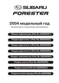
Руководство по техническому обслуживанию и ремонту автомобиля Subaru Impreza 2004 модельного года.
- Автор: —
- Издательство: Fuji Heavy Industries Ltd.
- Год издания: —
- Страниц: 3581
- Формат: PDF
- Размер: 96,7 Mb
Руководство по техническому обслуживанию и ремонту автомобиля Subaru Impreza 2008 модельного года.
- Автор: —
- Издательство: Fuji Heavy Industries Ltd.
- Год издания: —
- Страниц: 3744
- Формат: PDF
- Размер: 65,4 Mb
Руководство по эксплуатации и техническому обслуживанию автомобиля Subaru Impreza 2005 года выпуска.
- Автор: —
- Издательство: Fuji Heavy Industries Ltd.
- Год издания: 2004
- Страниц: 512
- Формат: PDF
- Размер: 10,0 Mb
Руководство по эксплуатации и техническому обслуживанию автомобиля Subaru Impreza 2007 года выпуска.
- Автор: —
- Издательство: Fuji Heavy Industries Ltd.
- Год издания: 2006
- Страниц: 464
- Формат: PDF
- Размер: 9,3 Mb
Руководство по эксплуатации и техническому обслуживанию автомобиля Subaru Impreza 2009 года выпуска.
- Автор: —
- Издательство: Fuji Heavy Industries Ltd.
- Год издания: 2008
- Страниц: 497
- Формат: PDF
- Размер: 7,7 Mb
Руководство по эксплуатации и техническому обслуживанию автомобией Subaru Impreza и Subaru XV 2012 года выпуска.
- Автор: —
- Издательство: Fuji Heavy Industries Ltd.
- Год издания: 2011
- Страниц: —
- Формат: PDF
- Размер: 184,2 Mb
Руководство по эксплуатации и техническому обслуживанию автомобиля Subaru Impreza 2000-2007 годов выпуска.
- Автор: —
- Издательство: MoToR
- Год издания: —
- Страниц: 512
- Формат: —
- Размер: —
Руководство по техническому обслуживанию и ремонту автомобиля Subaru Impreza 1993-2002 годов выпуска с бензиновыми двигателями объемом 1,5/1,6/1,8/2,0 л.
- Автор: —
- Издательство: Легион-Автодата
- Год издания: —
- Страниц: 656
- Формат: —
- Размер: —
Руководство по техническому обслуживанию и ремонту автомобилей Subaru Impreza/Impreza WRX/Impreza WRX STI с 2007 года выпуска с бензиновыми двигателями объемом 1,5/2,0/2,5 л.
- Автор: —
- Издательство: Легион-Автодата
- Год издания: 2012
- Страниц: 600
- Формат: —
- Размер: —

ДВИГАТЕЛЬ СУБАРУ ИМПРЕЗА. РАЗДЕЛ 1
ДВИГАТЕЛЬ СУБАРУ ИМПРЕЗА. РАЗДЕЛ 2
ТРАНСМИССИЯ
ШАССИ
ОБОРУДОВАНИЕ КУЗОВА СУБАРУ ИМПРЕЗА
ЭЛЕКТРОСИСТЕМА АВТОМОБИЛЯ СУБАРУ ИМПРЕЗАОБЩАЯ ИНФОРМАЦИЯ (PDF 1,11 Мб)
- Введение
- Как пользоваться руководством
- Спецификации
- Меры предосторожности
- Общие замечания
- Идентификация
- Рекомендуемые рабочие жидкости и расходные материалы
- Предпродажная подготовка
- Периодическое обслуживание
- Цели
- Периодичность
- Моторное масло
- Масляный фильтр
- Свечи зажигания
- Приводные ремни
- Ремень газораспределительного механизма (ГРМ)
- Зазоры клапанов
- Система подачи топлива
- Топливный фильтр
- Фильтр очистки воздуха
- Система охлаждения
- Охлаждающая жидкость
- Регулировка состава смеси холостого хода
- Сцепление
- Регулировка остановки на уклоне
- Трансмиссионное масло
- Трансмиссионная жидкость (ATF)
- Масло в переднем и заднем дифференциале
- Тормозная система
- Тормозная жидкость
- Тормозные диски и колодки
- Тормозные барабаны и накладки колодок
- Подвеска
- Колесные подшипники
- Шарниры полуосей и их чехлы
- Рулевая система (с усилителем)
- Подушки безопасности
ДВИГАТЕЛЬ СУБАРУ ИМПРЕЗА. РАЗДЕЛ 1 — Двигатель с одним распределительным валом (Single OverHead Cam — SOHC).
- Система впрыска топлива FU(SOHC) (PDF 1,22 Мб)
- Общее описание
- Блок дроссельной заслонки
- Впускной коллектор
- Датчик температуры охлаждающей жидкости на двигателе
- Датчик положения коленчатого вала
- Датчик положения распределительного вала
- Датчик детонации
- Датчик положения дроссельной заслонки
- Датчик температуры и давления входящего воздуха
- Датчик атмосферного давления
- Управляющий воздушный электромагнитный клапан системы холостого хода
- Электромагнитный клапан воздушного инжектора
- Топливный инжектор
- Передний датчик кислорода (A/F)
- Задний датчик кислорода
- Блок управления двигателем (Engine Control Module — ECM)
- Главное реле
- Реле топливного насоса
- Слив топлива из системы
- Топливный бак
- Напорный бензопровод
- Топливный насос
- Датчик уровня топлива
- Топливный фильтр
- Клапан отсечки подачи топлива
- Клапан возврата топлива
- Трубопроводы подачи топлива, возвратный трубопровод и трубопровод топливных паров
- Общие неисправности системы подачи топлива
- Контроль выбросов в окружающую среду (Дополнительные устройства контроля выбросов) (PDF 129 Кб) EC(SOHC)
- Общие указания
- Передний катализатор
- Задний катализатор
- Абсорбер
- Продувочный электромагнитный клапан
- Двусторонний клапан
- Система подачи воздуха IN(SOHC)(PDF 142 Кб)
- Общее описание
- Воздушный фильтр
- Корпус воздушного фильтра
- Воздуховод
- Камера резонатора
- Устройство двигателя. Механическая часть ME(SOHC) (PDF 1,84 Мб)
- Общие сведения
- Компрессия
- Холостой ход
- Угол опережения зажигания
- Разрежение во впускном коллекторе
- Давление масла в двигателе
- Давление топлива
- Зазоры клапанов
- Двигатель. Снятие и установка
- Крепление двигателя
- Подготовка к разборке двигателя
- Приводные ремни
- Шкив коленчатого вала
- Кожух ремня газораспределительного механизма (ГРМ)
- Ремень ГРМ
- Звездочка распределительного вала
- Звездочка коленчатого вала
- Рычаги клапанов (рокеры)
- Распределительный вал
- Головка блока цилиндров
- Блок цилиндров
- Общие неисправности двигателя
- Шумность двигателя
- Выпускная система EX(SOHC) (PDF 176 Кб)
- Общее описание
- Передняя часть выпускной трубы
- Средняя часть выпускной трубы
- Задняя часть выпускной трубы
- Глушитель
- Система охлаждения двигателя CO (PDF 990 Кб)
- Общее описание
- Радиатор. Система основного вентилятора
- Радиатор. Система дополнительного вентилятора
- Охлаждающая жидкость
- Насос охлаждающей жидкости
- Термостат
- Радиатор
- Крышка радиатора
- Радиатор. Основной вентилятор и мотор вентилятора
- Радиатор. Дополнительный вентилятор и мотор вентилятора
- Расширительный бачок
- Бачок наполнения системы охлаждения
- Общие неисправности системы охлаждения двигателя
- Система смазки двигателя LU (PDF 684 Кб)
- Общее описание
- Система поддержания давления масла
- Моторное масло
- Масляный насос
- Масляный картер и маслозаборная горловина с сетчатым фильтром
- Датчик давления масла
- Масляный охладитель
- Масляный фильтр
- Общие неисправности системы охлаждения двигателя
- Педаль газа и привод дроссельной заслонки SP (PDF 162 Кб)
- Общее описание
- Педаль газа
- Троссик педали газа
- Система зажигания IG(SOHC) (PDF 194 Кб)
- Общее описание
- Свечи зажигания
- Катушка зажигания и блок управления зажиганием
- Провода высокого напряжения
- Системы запуска двигателя Субару Импреза и заряда аккумулятора SC (PDF 406 Кб)
- Общее описание
- Стартер
- Генератор
- Аккумулятор
- Диагностика двигателя EN(SOHC)
Часть 1 (PDF 1,03 Мб)
- Общая диагностика
- Список вопросов для диагностики
- Общее описание
- Расположение основных элементов
- Блок управления двигателем и сигналы на входе/выходе
- Режим работы двигателя при проверке
- Блок управления трансмиссией и сигналы на входе/выходе
- Клемма для съема данных
- Прибор для общего сканирования OBD-II
- Диагностический прибор Subaru Select Monitor
- Чтение кода диагностики неисправностей
- Режим проверки
- Режим очистки памяти
- Режим обязательной проверки реле и клапанов
- Лампа индикации неисправности двигателя
- Диагностика неисправностей при запуске двигателя
- Список кодов неисправности
Часть 2 (PDF 1,12 Мб)
- Процедура устранения неисправностей, определенных по коду неисправности
- Общая диагностическая таблица
ДВИГАТЕЛЬ СУБАРУ ИМПРЕЗА. Двигатель с одним распределительным валом (Single OverHead Cam — SOHC), без встроенной системы диагностики (On-Board Diagnostics — OBD). Двигатель с турбонагнетателем и двумя распределительными валами (Double OverHead Cam — DOHC)
- Система впрыска топлива. FU(SOHCw/oOBD) (PDF 1,17 Мб)
- Общее описание
- Блок дроссельной заслонки
- Впускной коллектор
- Датчик температуры охлаждающей жидкости на двигателе
- Датчик положения коленчатого вала
- Датчик положения распределительного вала
- Датчик детонации
- Датчик положения дроссельной заслонки
- Датчик температуры и давления входящего воздуха
- Управляющий воздушный электромагнитный клапан системы холостого хода
- Топливный инжектор
- Датчик кислорода
- Блок управления двигателем
- Главное реле
- Реле топливного насоса
- Слив топлива из системы
- Топливный бак
- Напорный бензопровод
- Топливный насос
- Датчик уровня топлива
- Топливный фильтр
- Клапан отсечки подачи топлива
- Fuel Damper Valve
- Трубопроводы подачи топлива, возвратный трубопровод и трубопровод топливных паров.
- Общие неисправности системы подачи топлива
- Контроль выбросов в окружающую среду (Дополнительные устройства контроля выбросов) EC(SOHCw/oOBD) (PDF 123 Кб)
- Общие указания
- Передний катализатор
- Задний катализатор
- Абсорбер
- Продувочный электромагнитный клапан
- Двусторонний клапан
- Выпускная система EX(SOHCw/oOBD) (PDF 219 Кб)
- Общее описание
- Передняя часть выпускной трубы
- Средняя часть выпускной трубы
- Задняя часть выпускной трубы
- Глушитель
- Система зажигания Субару Импреза IG(SOHCw/oOBD) (PDF 194 Кб)
- Общее описание
- Свечи зажигания
- Катушка зажигания и блок управления зажиганием
- Провода высокого напряжения
- Диагностика двигателя Субару Импреза ME(SOHCw/oOBD)(PDF 970 Кб)
- Общая диагностика
- Список вопросов для диагностики
- Общее описание
- Расположение основных элементов
- Блок управления двигателем (Engine Control Module -ЕСМ) и сигналы на входе/выходе
- Диагностический прибор Subaru Select Monitor
- Чтение кода диагностики неисправностей
- Режим проверки
- Режим очистки памяти
- Режим обязательной проверки реле и клапанов
- Лампа индикации неисправности двигателя
- Диагностика неисправностей при запуске двигателя
- Список кодов неисправности
- Процедура устранения неисправностей, определенных по коду неисправности
- Общая диагностическая таблица
- Система впрыска топлива. FU(DOHC TURBO — Двигатель с турбонагнетателем и двумя распределительными валами (Double OverHead Cam — DOHC) (PDF 1,6 Мб).
- Общее описание
- Блок дроссельной заслонки
- Впускной коллектор
- Датчик температуры охлаждающей жидкости на двигателе
- Датчик положения коленчатого вала
- Датчик положения распределительного вала
- Датчик детонации
- Датчик положения дроссельной заслонки
- Датчик массы воздушного потока и давления входящего воздуха
- Датчик давления входящего воздуха
- Управляющий воздушный электромагнитный клапан системы холостого хода
- Топливный инжектор
- Блок клапана завихрителя воздуха
- Электромагнитный перепускной клапан системы турбонаддува
- Передний датчик кислорода
- Задний датчик кислорода
- Датчик температуры выхлопных газов
- Блок управления двигателем
- Главное реле
- Реле топливного насоса
- Fuel Pump Controller
- Слив топлива из системы
- Топливный бак
- Напорный бензопровод
- Топливный насос
- Датчик уровня топлива
- Дополнительный датчик уровня топлива
- Топливный фильтр
- Клапан отсечки подачи топлива
- Fuel Damper Valve
- Трубопроводы подачи топлива, возвратный трубопровод и трубопровод топливных паров.
- Общие неисправности системы подачи топлива
- Контроль выбросов в окружающую среду (Дополнительные устройства контроля выбросов) EC(DOHC TURBO) (PDF 90 Кб)
- Общие указания
- Передний катализатор
- Задний катализатор
- Предкатализатор
- Абсорбер
- Продувочный электромагнитный клапан
- Двусторонний клапан
- Система подачи воздуха IN(DOHC TURBO) (PDF 309 Кб)
- Общее описание
- Воздушный фильтр
- Воздухозаборник
- Воздуховод
- Интеркулер
- Турбонагнетатель
- Воздушный перепускной клапан
- Устройство двигателя Субару Импреза. Механическая часть. ME(DOHC TURBO)(PDF 1,89 Мб)
- Общие сведения
- Компрессия
- Холостой ход
- Угол опережения зажигания
- Разрежение во впускном коллекторе
- Давление масла в двигателе
- Давление топлива
- Зазоры клапанов
- Снятие и установка двигателя
- Крепление двигателя
- Подготовка к разборке двигателя
- Приводные ремни
- Шкив коленчатого вала
- Кожух ремня газораспределительного механизма (ГРМ)
- Ремень ГРМ
- Звездочка распределительного вала
- Звездочка коленчатого вала
- Распределительный вал
- Головка блока цилиндров
- Блок цилиндров
- Общие неисправности двигателя
- Шумность двигателя
- Выпускная система EX(DOHC TURBO) (PDF 292 Кб)
- Общее описание
- Передняя часть выпускной трубы
- Средняя часть выпускной трубы
- Соединительная труба
- Задняя часть выпускной трубы
- Глушитель
- Система зажигания Субару Импреза IG(DOHC TURBO) (PDF 143 Кб)
- Общее описание
- Свечи зажигания
- Катушка зажигания и блок управления зажиганием
- Диагностика двигателя Субару Форестер
Часть 1 (PDF 874 Кб)
- Общая диагностика
- Список вопросов для диагностики
- Общее описание
- Расположение основных элементов
- Блок управления двигателем (Engine Control Module -ЕСМ) и сигналы на входе/выходе
- Режим работы двигателя при проверке
- Клемма для съема данных
- Прибор для общего сканирования OBD-II
- Диагностический прибор Subaru Select Monitor
- Чтение кода диагностики неисправностей
- Режим проверки
- Режим очистки памяти
- Режим обязательной проверки реле и клапанов
- Лампа индикации неисправности двигателя
- Диагностика неисправностей при запуске двигателя
- Список кодов неисправности
Часть 2 (PDF 1,24 Мб)
- Процедура устранения неисправностей, определенных по коду неисправности
- Общая диагностическая таблица
ТРАНСМИССИЯ
- Органы управления Субару Импреза (PDF 309 Кб)
- Общее описание
- Рычаг селектора
- Троссик селектора
- Механическая трансмиссия. Рычаг переключения передач
- Механическая трансмиссия. Рычаг демультипликатора
- Троссик демультипликатора
- Общая диагностика
- Автоматическая трансмиссия (PDF 753 Кб)
- Общее описание
- Трансмиссионная жидкость (ATF)
- Масло для дифференциала
- Тестирование на ходу
- Тестирование на стоящем автомобиле
- Проверка временной задержки
- Проверка давления
- Проверка давления в раздаточной муфте
- Снятие и установка автоматической трансмиссии
- Крепление автоматической трансмиссии
- Сальник удлинительной коробки
- Переключатель замедлителя
- Передний датчик скорости автомобиля
- Задний датчик скорости автомобиля
- Датчик скорости гидротрансформатора
- Корпус управляющего клапана
- Соленоиды переключения, рабочий соленоид, датчик температуры трансмиссионной жидкости (ATF)
- Фильтр трансмиссионной жидкости (ATF)
- Блок управления трансмиссией
- Труба и патрубок охлаждения трансмиссионной жидкости (ATF)
- Автоматическая трансмиссия. Диагностика (PDF 902 Кб)
- Общая диагностика
- Список вопросов для диагностики
- Общее описание
- Расположение основных элементов
- Блок управления трансмиссией и сигналы на входе/выходе
- Диагностический прибор Subaru Select Monitor
- Чтение кода диагностики неисправностей
- Режим проверки
- Режим очистки памяти
- Световой индикатор «Power»
- Список кодов диагностики неисправностей
- Диагностика для светового индикатора «Power»
- Диагностика для монитора «Select Monitor Communication»
- Диагностика с использованием кода неисправности
- Диагностика для кода «Нет неисправностей»
- Диагностика по симптомам
- Механическая трансмиссия и дифференциал (PDF 1,87 Мб)
- Общее описание
- Масло в механической трансмиссии
- Снятие и установка механической трансмиссии
- Крепление трансмиссии
- Масляный сальник
- Переключатели и навесное оборудование
- Датчик скорости автомобиля
- Подготовка к ремонту
- Раздаточная коробка и удлинитель
- Rear Case
- Ведущая шестерня раздаточной коробки
- Ведомая шестерня раздаточной коробки
- Центральный дифференциал
- Фиксирующая втулка заднего хода
- Коробка передач
- Основной вал коробки без овердрайва
- Основной вал коробки с овердрайвом
- Входящий вал
- Вал ведущей шестерни
- Передний дифференциал
- Шестерня спидометра
- Промежуточная шестерня заднего хода
- Переключающая вилка и направляющий вал
- Обратная шестерня
- Общая диагностика
- Сцепление (PDF 1 Мб)
- Общее описание
- Диск и корзина сцепления
- Маховик
- Выжимной подшипник и рычаг
- Рабочий цилиндр
- Главный цилиндр
- Трубка и шланг сцепления
- Рабочая жидкость сцепления
- Прокачка сцепления
- Педаль сцепления
- Clutch Cable
- Переключатель сцепления
- Общая диагностика
ШАССИ
- Передняя подвеска (PDF 354 Кб)
- Общее описание
- Установка колес
- Рычаг передней подвески
- Передняя шаровая опора
- Передняя стойка
- Передний стабилизатор устойчивости
- Передняя поперечина
- Общая диагностика
- Задняя подвеска (PDF 364 Кб)
- Общее описание
- Установка колес
- Задний стабилизатор устойчивости
- Задний продольный рычаг
- Задняя стойка
- Задний поперечный рычаг
- Задняя поперечина
- Общая диагностика
- Колеса и шины Субару Импреза (PDF 87,3 Кб)
- Общее описание
- Шины
- Стальные колесные диски
- Алюминиевые колесные диски
- Балансировка колес
- Шины типа Т
- Full Wheel Cap
- Общая диагностика
- Дифференциалы (PDF 994 Кб)
- Общее описание
- Масло для дифференциалов
- Передний дифференциал
- Задний дифференциал для типа Т
- Задний дифференциал для типа VA
- Передний сальник заднего дифференциала
- Боковой сальник заднего дифференциала
- Крепежная балка заднего дифференциала
- Общая диагностика
- Раздаточная коробка (PDF 47,2 Кб)
- Общее описание
- Раздаточная коробка и удлинитель для механической трансмиссии
- Раздаточная муфта и удлинитель для автоматической трансмиссии
- Сальник
- Ведущая шестерня раздаточной коробки (механическая трансмиссия)
- Ведомая шестерня раздаточной коробки (механическая трансмиссия)
- Понижающая ведущая шестерня без VTD
- Понижающая ведомая шестерня без VTD
- Центральный (межосевой) дифференциал
- Проверка давления в раздаточной муфте
- Рабочий соленоид и корпус клапана в раздаточной муфте
- Карданный вал и привод к колесам Субару Импреза (PDF 675 Кб)
- Общее описание
- Карданный вал
- Привод передних колес
- Привод задних колес
- Передняя полуось
- Задняя полуось
- Общая диагностика
- Антиблокировочная система (Anti-Blocking System — ABS) Субару Импреза (PDF 266 Кб)
- Общее описание
- Управляющий блок ABS и гидравлический управляющий блок
- Блок управления очередностью
- Передний датчик ABS
- Задний датчик ABS
- Переднее колесо
- Заднее колесо
- Датчик ускорения
- Антиблокировочная система (ABS) Субару Импреза. Диагностика (PDF 1,22 Мб)
- Общая диагностика
- Список вопросов для диагностики
- Общее описание
- Расположение основных элементов
- Блок управления и сигналы на входе/выходе
- Диагностический прибор Subaru Select Monitor
- Чтение кода диагностики неисправностей
- Режим проверки
- Режим очистки памяти
- Световой индикатор предупреждения о работе ABS
- Список кодов диагностики неисправностей
- Диагностическая карта для диагностического соединения
- Диагностическая карта для монитора «Subaru Select Monitor Communication»
- Общая диагностика
- Тормоза Субару Импреза (PDF 1,31 Мб)
- Общее описание
- Передние тормозные колодки
- Передний тормозной диск
- Передние дисковые тормоза
- Задние тормозные колодки
- Задний тормозной диск
- Задние дисковые тормоза
- Задние тормозные башмаки
- Задний тормозной барабан
- Задние барабанные тормоза
- Главный цилиндр
- Усилитель тормозов
- Распределяющий клапан
- Тормозная жидкость
- Прокачка тормозов
- Тормозные шланги
- Тормозной трубопровод
- Блок для удержания на уклоне
- Тормозная педаль
- Выключатель стоп — сигнала
- Общая диагностика
- Стояночный тормоз (PDF 167 Кб)
- Общее описание
- Рычаг стояночного тормоза
- Троссик стояночного тормоза
- Стояночный тормоз (задние дисковые тормоза)
- Общая диагностика
- Рулевое управление с гидроусилителем(PDF 1,99 Мб)
- Общее описание
- Рулевое колесо
- Карданный шарнир
- Наклонная рулевая колонка
- Рулевой механизм (левосторонняя модель — LHD)
- Рулевой механизм (правосторонняя модель RHD)
- Valve Housing Oil Seal
- Pinion and Valve Oil Seal
- Rack Housing Oil Seal
- Rack Piston Seal Ring and O- ring
- Трубопроводы (левосторонняя модель — LHD)
- Трубопроводы (правосторонняя модель RHD)
- Масляный насос
- Бачок с рабочей жидкостью
- Рабочая жидкость рулевой системы
- Общая диагностика
ОБОРУДОВАНИЕ КУЗОВА СУБАРУ ИМПРЕЗА
- Климатическая система Субару Импреза (Нагревание, вентиляция и кондиционирование воздуха) (PDF 576 Кб)
- Общее описание
- Давление хладагента с системой калибрования трубопроводов
- Слив хладагента
- Заполнение хладагентом
- Контроль утечки хладагента
- Масло в компрессоре
- Мотор вентилятора
- Силовой транзистор (Резистор тепла воздушного потока)
- Радиатор нагревателя
- Управляющий блок
- Компрессор
- Конденсатор
- Heater Cooling Unit
- Испаритель
- Hose and Tube
- Реле и предохранители
- Переключатель давления (Двухпозиционный выключатель)
- Датчик окружающей среды (Автоматическая A/C модель)
- Sun-load Sensor (Auto A/C Model)
- Решетка вентилятора
- Трубопровод нагревателя
- Воздуховод вентилятора нагревателя
- Общая диагностика
- Климатическая система Субару Импреза (Диагностика) (PDF 411 Кб)
- Общая диагностика
- Общее описание
- Расположение основных элементов
- Блок управления климатической системой и сигналы на входе/выходе
- Диагностическая карта системы диагностики
- Диагностика повреждений системы кондиционирования воздуха
- Diagnostic Procedure for Actuators
- Диагностика датчиков
- Диагностика по симптомам
- Подушки безопасности в Субару Импреза (PDF 490 Кб)
- Общее описание
- Разъем подушки безопасности
- Места осмотра после аварии
- Блок подушки безопасности водителя
- Блок подушки безопасности пассажира
- Блок боковой подушки безопасности
- Управляющий блок подушки безопасности
- Датчик боковой подушки безопасности
- Вращающееся соединение
- Передний дополнительный датчик
- Обращение с блоком подушки безопасности (установленного в автомобиле)
- Обращение с блоком подушки безопасности (после снятия с автомобиля)
- Подушки безопасности в Субару Импреза. Диагностика (PDF 751 Кб)
- Общая диагностика
- Список вопросов для диагностики
- Общее описание
- Расположение основных элементов
- Блок управления подушками безопасности и сигналы на входе/выходе
- Разъем подушек безопасности
- Световой индикатор подушек безопасности
- Чтение кода диагностики неисправностей
- Режим проверки
- Режим очистки памяти
- Неисправности светового индикатора подушек безопасности
- Список кодов диагностики неисправностей
- Диагностическая карта с кодами неисправности
- Ремни безопасности в Субару Импреза (PDF 207 Кб)
- Общее описание
- Места осмотра после аварии
- Передние ремни безопасности
- Задние ремни безопасности
- Обращение с преднатяжителями
- Система освещения в Субару Импреза (PDF 736 Кб)
- Общее описание
- Фары. Передние и задние огни
- Передние противотуманные фары
- Задние противотуманные огни
- Сигналы поворота и аварийная сигнализация
- Фонарь заднего хода
- Тормозные сигналы
- Система внутреннего освещения
- Система стабилизации фар
- Комбинированный переключатель света
- Блок фар
- Лампы фар
- Лампы блока передних сигналов поворота
- Лампы габаритных огней
- Блок передних противотуманных фар
- Лампы передних противотуманных фар
- Блок комбинации задних сигналов
- Лампы тормозного сигнала
- Лампа фонаря заднего хода
- Лампы задних сигналов поворота
- Лампы задних противотуманных огней
- Подсветка номерного знака
- Повторитель тормозного сигнала
- Боковые сигналы поворота
- Переносной фонарь
- Освещение салона
- Освещение багажника
- Trunk Room Light
- Освещение перчаточного ящика
- Стеклоочистители и омыватели стекол (PDF 327 Кб)
- Общее описание
- Стеклоочистители и омыватели
- Комбинированный переключатель (Стеклоочистители)
- Лезвия стеклоочистителей
- Бачок омывателя и мотор
- Поводки передних стеклоочистителей
- Мотор и привод передних стеклоочистителей
- Передние омыватели
- Поводок заднего стеклоочистителя
- Мотор заднего стеклоочистителя
- Задний омыватель
- Управляющее реле стеклоочистителей
- Дополнительное оборудование салона Субару Импреза (PDF 122 Кб)
- Общее описание
- Радио
- Прикуриватель
- Панель крепления радиоприемника
- Передние динамики
- Громкоговоритель для воспроизведения верхних (звуковых) частот
- Задние динамики
- Антенна
- Прикуриватель. Снятие и установка
- Звуковой сигнал (PDF 74,7 Кб)
- Общее описание
- Звуковой сигнал
- Снятие и установка звукового сигнала
- Включатель звукового сигнала
- Стекла/окна/зеркала Субару Импреза (PDF 591 Кб)
- Общее описание
- Электрические стеклоподъемники
- Противозапотеватель заднего стекла
- Дистанционное управление зеркалами заднего вида
- Стекла передних дверей
- Мотор и привод передних стеклоподъемников
- Стекла задних дверей
- Мотор и привод задних стеклоподъемников
- Лобовое стекло
- Стекло двери багажного отделения
- Задние боковые стекла
- Стекло заднего окна
- Стекло люка на крыше
- Внутреннее зеркало заднего вида
- Выключатель стеклоподъемников
- Противозапотеватель заднего стекла. Проверка и ремонт
- Наружные зеркала заднего вида
- Наружные зеркала заднего вида .Замена
- Переключатель дистанционного управления наружными зеркалами
- Кузов автомобиля Субару Импреза
- Панель приборов / Информация для водителя в Субару Импреза (PDF 236 Кб)
- Общее описание
- Комбинация приборов
- Комбинация приборов. Снятие и установка
- Спидометр
- Тахометр
- Указатель уровня топлива
- Указатель температуры охлаждающей жидкости
- Датчик окружающей среды
- Сидения (PDF 270 Кб)
- Общее описание
- Переднее сидение
- Заднее сидение
- Замки и система безопасности Субару Импреза (PDF 527 Кб)
- Общее описание
- Система управления дверными замками
- Система управления дверями без ключа
- Дистанционное управление передними дверями внутри салона
- Наружные ручки передних дверей
- Защелка замка передних дверей
- Привод замка передних дверей
- Дистанционное управление задними дверями внутри салона
- Наружные ручки задних дверей
- Защелка замка задних дверей
- Привод замка задних дверей
- Наружная ручка двери багажного отделения
- Защелка замка двери багажного отделения
- Привод замка двери багажного отделения
- Trunk Lid Lock Assembly
- Замок капота
- Система открывания капота и люка бензобака
- Замок зажигания
- Цилиндр замка зажигания
- Управляющий блок иммобилайзера
- Антенна иммобилайзера
- Управляющий блок системы управления дверями без ключа
- Передатчик системы управления дверями без ключа
- Иммобилайзер. Диагностика (PDF 255 Кб)
- Общая диагностика
- Общее описание
- Расположение основных элементов
- Блок управления иммобилайзером и сигналы на входе/выходе
- Диагностический прибор Subaru Select Monitor
- Чтение кода диагностики неисправностей
- Режим очистки памяти
- Диагностическая карта для светового индикатора иммобилайзера
- Список кодов диагностики неисправностей
- Диагностическая карта с кодами неисправности
- Люк на крыше Субару Импреза (PDF 188 Кб)
- Общее описание
- Система управления люком
- Крышка люка
- Агрегаты люка
- Мотор люка
- Переключатель люка
- Элементы внешней/внутренней отделки Субару Импреза (PDF 578 Кб)
- Общее описание
- Front Grille
- Передний поддон
- Передний бампер
- Задний бампер
- Подкрылки
- Накладка капота
- Spoiler
- Side Sill Spoiler
- Панели передних дверей
- Панели задних дверей
- Перчаточный ящик
- Накладки боковины крыши
- Консольный ящик
- Панель инструментов
- Верхние внутренние панели
- Нижние внутренние панели
- Задние боковые панели
- Солнечные козырьки
- Панели крыши
- Панели двери багажного отделения
- Rear Shelf Trim
- Trunk Trim
- Покрытие пола
- Покрытие пола багажного отделения
- Trunk Room Mat
- Внешние панели кузова Субару Импреза (PDF 303 Кб)
- Общее описание
- Капот
- Крылья
- Передние двери
- Уплотнения передних дверей
- Задние двери
- Уплотнения задних дверей
- Trunk Lid Panel
- Дверь багажного отделения
- Система поддержания постоянной скорости Субару Импреза (Круз контроль) (PDF 171 Кб)
- Общее описание
- Привод
- Блок круз контроля
- Основной выключатель круз контроля
- Управляющий выключатель круз контроля
- Выключатель Стоп и Тормоз
- Выключатель сцепления
- Выключатель замедлителя
- Система поддержания постоянной скорости Субару Импреза (Круз контроль). Диагностика (PDF 308 Кб)
- Общая диагностика
- Общее описание
- Расположение основных элементов
- Блок управления круз контролем и сигналы на входе/выходе
- Диагностический прибор Subaru Select Monitor
- Диагностическая карта с симптомами
- Диагностическая карта с кодами неисправности
ЭЛЕКТРОСИСТЕМА АВТОМОБИЛЯ СУБАРУ ИМПРЕЗА
- Электрическая система Субару Импреза
Часть 1 (PDF 1,02 Мб)
- Общая диагностика
- Предосторожности при работе
- Super Multiple Junction (SMJ)
- Маршрутизация подачи напряжения
- Схема выхода на «землю»
- Подушки безопасности
- Кондиционер
- Антиблокировочная система
- Система управления автоматической трансмиссией
- Аудио система
- Система зарядки
- Комбинация приборов
- Круз контроль
- Замки дверей
Часть 2 (PDF 1 Мб)
- Engine Coolant Temperature Gauge System
- Электрическая система двигателя Субару Импреза
- Система указателя уровня топлива
- Постоянно действующая двухдиапазонная система
- Подача напряжения на переднее оборудование
- Система стабилизации фар
- Звуковой сигнал
- Иммобилайзер
- Система управления дверями без ключа
- Фонарь заднего хода
- Габаритные огни и освещение
- Передние противотуманные фары
- Фары
Часть 3 (PDF 1,26 Мб)
- Внутреннее освещение
- Тормозные сигналы
- Сигналы поворота и аварийная сигнализация
- Указатели давления масла
- Указатель наружной температуры
- Указатель включения парковочного тормоза и уровня тормозной жидкости
- Стеклоподъемники
- Вентилятор радиатора
- Задние противотуманные фары
- Противозапотеватель заднего стекла
- Зеркала заднего вида с дистанционным управлением
- Система предупреждения о незастегнутых ремнях безопасности
- Стартер
- Люк на крыше Субару Импреза
- Передние стеклоочистители и омыватели
- Задний стеклоочиститель и омыватель
- Общая схема разводки проводов
- Разводка жгутов в передней части автомобиля Субару Импреза
- Разводка жгутов на перегородке (в моторном отсеке)
- Разводка жгутов на перегородке (в салоне)
- Разводка жгутов на двигателе и трансмиссии
- Жгут проводов панели инструментов
- Rear Wiring Harness, Bulkhead Wiring Harness, Roof Cord and Fuel Tank Cord
- Разводка жгутов в дверях
- Rear Wiring Harness and Trunk Lid Cord
- Rear Wiring Harness and Rear Gate Cord