- Manuals
- Brands
- Mitsubishi Electric Manuals
- Amplifier
- Melservo MR-J3-A
Manuals and User Guides for Mitsubishi Electric Melservo MR-J3-A. We have 1 Mitsubishi Electric Melservo MR-J3-A manual available for free PDF download: Instruction Manual
![]()
General-Purpose AC Servo

 J3 Series
Built-in Positioning Function
MODEL
MR-J3-
 T
T
SERVO AMPLIFIER INSTRUCTION MANUAL (CC-Link)
E

 Safety Instructions
 Safety Instructions
(Always read these instructions before using the equipment.)
Do not attempt to install, operate, maintain or inspect the servo amplifier and servo motor until you have read through this Instruction Manual, Installation guide, Servo motor Instruction Manual (Vol.2) and appended documents carefully and can use the equipment correctly. Do not use the servo amplifier and servo motor until you have a full knowledge of the equipment, safety information and instructions.
In this Instruction Manual, the safety instruction levels are classified into «WARNING» and «CAUTION».
Indicates that incorrect handling may cause hazardous conditions, resulting in death or severe injury.
Indicates that incorrect handling may cause hazardous conditions, resulting in medium or slight injury to personnel or may cause physical
damage.
Note that the CAUTION level may lead to a serious consequence according to conditions. Please follow the instructions of both levels because they are important to personnel safety.
What must not be done and what must be done are indicated by the following diagrammatic symbols.
 : Indicates what must not be done. For example, «No Fire» is indicated by
  .
.  : Indicates what must be done. For example, grounding is indicated by
  .
.
In this Instruction Manual, instructions at a lower level than the above, instructions for other functions, and so on are classified into «POINT».
After reading this installation guide, always keep it accessible to the operator.
A — 1

1. To prevent electric shock, note the following
 WARNING
Before wiring or inspection, turn off the power and wait for 15 minutes or more until the charge lamp turns off. Then, confirm that the voltage between P(  ) and N( ) is safe with a voltage tester and others. Otherwise, an electric shock may occur. In addition, always confirm from the front of the servo amplifier, whether the charge lamp is off or not.
Connect the servo amplifier and servo motor to ground.
Any person who is involved in wiring and inspection should be fully competent to do the work.
Do not attempt to wire the servo amplifier and servo motor until they have been installed. Otherwise, you may get an electric shock.
Operate the switches with dry hand to prevent an electric shock.
The cables should not be damaged, stressed, loaded, or pinched. Otherwise, you may get an electric shock.
During power-on or operation, do not open the front cover of the servo amplifier. You may get an electric shock.
Do not operate the servo amplifier with the front cover removed. High-voltage terminals and charging area are exposed and you may get an electric shock.
Except for wiring or periodic inspection, do not remove the front cover even of the servo amplifier if the power is off. The servo amplifier is charged and you may get an electric shock.
2. To prevent fire, note the following
 CAUTION
Install the servo amplifier, servo motor and regenerative resistor on incombustible material. Installing them directly or close to combustibles will lead to a fire.
Always connect a magnetic contactor (MC) between the main circuit power supply and L1, L2, and L3 of the servo amplifier, and configure the wiring to be able to shut down the power supply on the side of the servo amplifier’s power supply. If a magnetic contactor (MC) is not connected, continuous flow of a large current may cause a fire when the servo amplifier malfunctions.
When a regenerative resistor is used, use an alarm signal to switch main power off. Otherwise, a regenerative transistor fault or the like may overheat the regenerative resistor, causing a fire.
3. To prevent injury, note the follow
 CAUTION
Only the voltage specified in the Instruction Manual should be applied to each terminal, Otherwise, a burst, damage, etc. may occur.
Connect the terminals correctly to prevent a burst, damage, etc.
Ensure that polarity (  , ) is correct. Otherwise, a burst, damage, etc. may occur.
Take safety measures, e.g. provide covers, to prevent accidental contact of hands and parts (cables, etc.) with the servo amplifier heat sink, regenerative resistor, servo motor, etc. since they may be hot while power is on or for some time after power-off. Their temperatures may be high and you may get burnt or a parts may damaged.
During operation, never touch the rotating parts of the servo motor. Doing so can cause injury.
A — 2
4. Additional instructions
The following instructions should also be fully noted. Incorrect handling may cause a fault, injury, electric shock, etc.
(1) Transportation and installation
 CAUTION
Transport the products correctly according to their weights.
Stacking in excess of the specified number of products is not allowed. Do not carry the servo motor by the cables, shaft or encoder.
Do not hold the front cover to transport the servo amplifier. The servo amplifier may drop. Install the servo amplifier in a load-bearing place in accordance with the Instruction Manual. Do not climb or stand on servo equipment. Do not put heavy objects on equipment.
The servo amplifier and servo motor must be installed in the specified direction.
Leave specified clearances between the servo amplifier and control enclosure walls or other equipment.
Do not install or operate the servo amplifier and servo motor which has been damaged or has any parts missing.
Provide adequate protection to prevent screws and other conductive matter, oil and other combustible matter from entering the servo amplifier and servo motor.
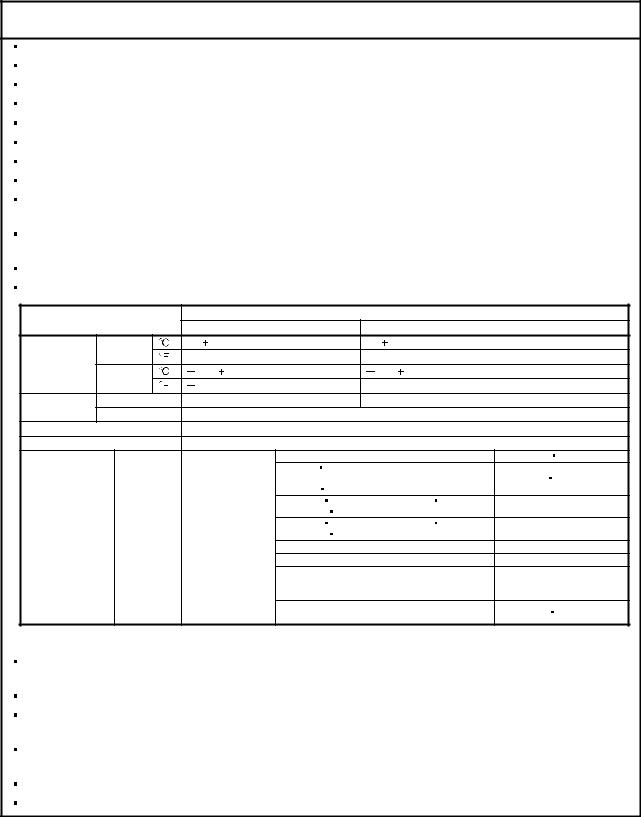
Do not drop or strike servo amplifier or servo motor. Isolate from all impact loads. When you keep or use it, please fulfill the following environmental conditions.
|
Environment |
Conditions |
||||||||||
|
Servo amplifier |
Servo motor |
||||||||||
|
Ambient |
In operation |
[ |
] |
0 to 55 (non-freezing) |
0 to |
40 (non-freezing) |
|||||
|
[ |
] |
32 to 131 (non-freezing) |
32 to 104 (non-freezing) |
||||||||
|
temperature |
In storage |
[ |
] |
20 to 65 (non-freezing) |
15 to 70 (non-freezing) |
||||||
|
[ |
] |
4 to 149 (non-freezing) |
5 to 158 (non-freezing) |
||||||||
|
Ambient |
In operation |
90%RH or less (non-condensing) |
80%RH or less (non-condensing) |
||||||||
|
humidity |
In storage |
90%RH or less (non-condensing) |
|||||||||
|
Ambience |
Indoors (no direct sunlight) Free from corrosive gas, flammable gas, oil mist, dust and dirt |
||||||||||
|
Altitude |
Max. 1000m (3280 ft) above sea level |
||||||||||
|
HF-MP series |
HF-KP series |
X |
Y: 49 |
||||||||
|
HF-SP51 |
81 |
HF-SP52 to 152 |
X |
Y: 24.5 |
|||||||
|
HF-SP524 to 1524 |
HC-RP Series |
||||||||||
|
HC-UP72 |
152 |
||||||||||
|
HF-SP121 |
201 |
HF-SP202 352 |
X: 24.5 Y: 49 |
||||||||
|
HF-SP2024 |
3524 |
HC-UP202 to 502 |
|||||||||
|
(Note) |
HF-SP301 |
421 |
HF-SP502 702 |
X: 24.5 Y: 29.4 |
|||||||
|
[m/s2] |
5.9 or less |
HF-SP5024 |
7024 |
||||||||
|
Vibration |
HC-LP52 to 152 |
X: 9.8 Y: 24.5 |
|||||||||
|
HC-LP202 to 302 |
X: 19.6 Y: 49 |
||||||||||
|
HA-LP601 to 12K1 |
HA-LP701M to 15K1M |
||||||||||
|
HA-LP502 to 22K2 |
HA-LP6014 to 12K14 |
X: 11.7 Y: 29.4 |
|||||||||
|
HA-LP701M4 to 15K1M4 |
HA-LP11K24 to 22K24 |
||||||||||
|
HA-LP15K1 to 25K1 |
HA-LP37K1M |
X |
Y: 9.8 |
||||||||
|
HA-LP15K14 to 20K14 |
HA-LP22K1M4 |
||||||||||
Note. Except the servo motor with a reduction gear.
Securely attach the servo motor to the machine. If attach insecurely, the servo motor may come off during operation.
The servo motor with a reduction gear must be installed in the specified direction to prevent oil leakage.
Take safety measures, e.g. provide covers, to prevent accidental access to the rotating parts of the servo motor during operation.
Never hit the servo motor or shaft, especially when coupling the servo motor to the machine. The encoder may become faulty.
Do not subject the servo motor shaft to more than the permissible load. Otherwise, the shaft may break. When the equipment has been stored for an extended period of time, consult Mitsubishi.
A — 3
(2) Wiring
 CAUTION
Wire the equipment correctly and securely. Otherwise, the servo motor may operate unexpectedly.
Do not install a power capacitor, surge absorber or radio noise filter (FR-BIF-(H) option) between the servo motor and servo amplifier.
Connect the wires to the correct phase terminals (U, V, W) of the servo amplifier and servo motor. Not doing so may cause unexpected operation.
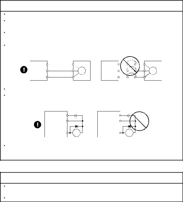
Connect the servo motor power terminal (U, V, W) to the servo motor power input terminal (U, V, W) directly. Do not let a magnetic contactor, etc. intervene.
|
Servo amplifier |
U |
Servo motor |
Servo amplifier |
U |
Servo motor |
||
|
U |
U |
||||||
|
V |
V |
||||||
|
V |
M |
V |
M |
||||
|
W |
W |
||||||
|
W |
W |
||||||
Do not connect AC power directly to the servo motor. Otherwise, a fault may occur.
The surge absorbing diode installed on the DC output signal relay of the servo amplifier must be wired in the specified direction. Otherwise, the forced stop (EMG) and other protective circuits may not operate.
|
Servo amplifier |
Servo amplifier |
|
24VDC |
24VDC |
|
DOCOM |
DOCOM |
|
DICOM |
DICOM |
|
RA |
RA |
When the cable is not tightened enough to the terminal block (connector), the cable or terminal block (connector) may generate heat because of the poor contact. Be sure to tighten the cable with specified torque.
(3) Test run adjustment
 CAUTION
Before operation, check the parameter settings. Improper settings may cause some machines to perform unexpected operation.
The parameter settings must not be changed excessively. Operation will be insatiable.
A — 4
(4) Usage
 CAUTION
Provide an external emergency stop circuit to ensure that operation can be stopped and power switched off immediately.
Any person who is involved in disassembly and repair should be fully competent to do the work.
Before resetting an alarm, make sure that the run signal of the servo amplifier is off to prevent an accident. A sudden restart is made if an alarm is reset with the run signal on.
Do not modify the equipment.
Use a noise filter, etc. to minimize the influence of electromagnetic interference, which may be caused by electronic equipment used near the servo amplifier.
Burning or breaking a servo amplifier may cause a toxic gas. Do not burn or break a servo amplifier. Use the servo amplifier with the specified servo motor.
The electromagnetic brake on the servo motor is designed to hold the motor shaft and should not be used for ordinary braking.
For such reasons as service life and mechanical structure (e.g. where a ball screw and the servo motor are coupled via a timing belt), the electromagnetic brake may not hold the motor shaft. To ensure safety, install a stopper on the machine side.
(5) Corrective actions
 CAUTION
When it is assumed that a hazardous condition may take place at the occur due to a power failure or a product fault, use a servo motor with an electromagnetic brake or an external brake mechanism for the purpose of prevention.
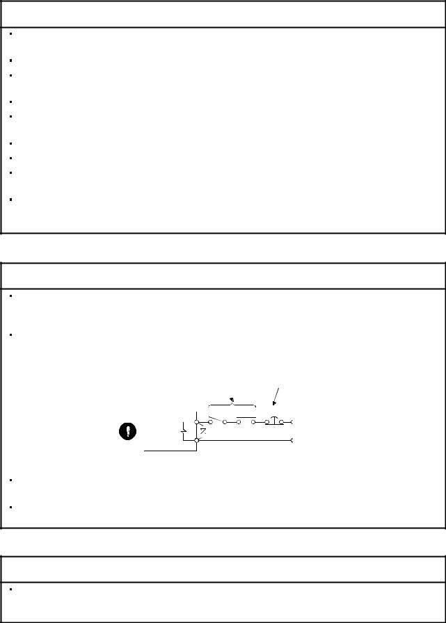
Configure the electromagnetic brake circuit so that it is activated not only by the servo amplifier signals but also by an external forced stop (EMG).
Contacts must be open when servo-off, when an trouble (ALM) and when an electromagnetic brake interlock (MBR). 
Circuit must be opened during forced stop (EMG).
SON RA EMG
24VDC
Electromagnetic brake
When any alarm has occurred, eliminate its cause, ensure safety, and deactivate the alarm before restarting operation.
When power is restored after an instantaneous power failure, keep away from the machine because the machine may be restarted suddenly (design the machine so that it is secured against hazard if restarted).
(6) Maintenance, inspection and parts replacement
 CAUTION
With age, the electrolytic capacitor of the servo amplifier will deteriorate. To prevent a secondary accident due to a fault, it is recommended to replace the electrolytic capacitor every 10 years when used in general environment. Please consult our sales representative.
A — 5

(7) General instruction
To illustrate details, the equipment in the diagrams of this Specifications and Instruction Manual may have been drawn without covers and safety guards. When the equipment is operated, the covers and safety guards must be installed as specified. Operation must be performed in accordance with this Specifications and Instruction Manual.
About processing of waste
 About processing of waste
When you discard servo amplifier, a battery (primary battery), and other option articles, please follow the law of each country (area).
 FOR MAXIMUM SAFETY
These products have been manufactured as a general-purpose part for general industries, and have not been designed or manufactured to be incorporated in a device or system used in purposes related to human life.
Before using the products for special purposes such as nuclear power, electric power, aerospace, medicine, passenger movement vehicles or under water relays, contact Mitsubishi.
These products have been manufactured under strict quality control. However, when installing the product where major accidents or losses could occur if the product fails, install appropriate backup or failsafe functions in the system.
 EEP-ROM life
The number of write times to the EEP-ROM, which stores parameter settings, etc., is limited to 100,000. If the total number of the following operations exceeds 100,000, the servo amplifier and/or converter unit may fail when the EEP-ROM reaches the end of its useful life.
Write to the EEP-ROM due to parameter setting changes Home position setting in the absolute position detection system Write to the EEP-ROM due to device changes
Write to the EEP-ROM due to point table changes
Precautions for Choosing the Products
Mitsubishi will not be held liable for damage caused by factors found not to be the cause of Mitsubishi; machine damage or lost profits caused by faults in the Mitsubishi products; damage, secondary damage, accident compensation caused by special factors unpredictable by Mitsubishi; damages to products other than Mitsubishi products; and to other duties.
A — 6

COMPLIANCE WITH EC DIRECTIVES
1. WHAT ARE EC DIRECTIVES?
The EC directives were issued to standardize the regulations of the EU countries and ensure smooth distribution of safety-guaranteed products. In the EU countries, the machinery directive (effective in January, 1995), EMC directive (effective in January, 1996) and low voltage directive (effective in January, 1997) of the EC directives require that products to be sold should meet their fundamental safety requirements and carry the CE marks (CE marking). CE marking applies to machines and equipment into which servo amplifiers have been installed.
(1)EMC directive
The EMC directive applies not to the servo units alone but to servo-incorporated machines and equipment. This requires the EMC filters to be used with the servo-incorporated machines and equipment to comply with the EMC directive. For specific EMC directive conforming methods, refer to the EMC Installation Guidelines (IB(NA)67310).
(2)Low voltage directive
The low voltage directive applies also to servo units alone. Hence, they are designed to comply with the low voltage directive.
This servo is certified by TUV, third-party assessment organization, to comply with the low voltage directive.
(3)Machine directive
Not being machines, the servo amplifiers need not comply with this directive.
2. PRECAUTIONS FOR COMPLIANCE
(1)Servo amplifiers and servo motors used
Use the servo amplifiers and servo motors which comply with the standard model.
|
Servo amplifier |
:MR-J3-10T to MR-J3-22KT |
|
|
MR-J3-10T1 to MR-J3-40T1 |
||
|
MR-J3-60T4 to MR-J3-22KT4 |
||
|
Servo motor |
:HF-MP |
|
|
HF-KP |
||
|
HF-SP |
(Note) |
|
|
HF-SP |
4 (Note) |
|
|
HC-RP |
||
|
HC-UP |
||
|
HC-LP |
||
|
HA-LP |
(Note) |
|
|
HA-LP |
4 (Note) |
Note. For the latest information of compliance, contact Mitsubishi.
A — 7
(2)Configuration
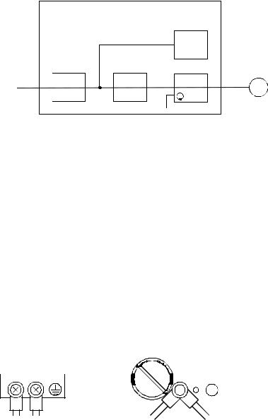
The control circuit provide safe separation to the main circuit in the servo amplifier.
|
Control box |
||||||||||||||
|
Reinforced |
||||||||||||||
|
insulating type |
||||||||||||||
|
24VDC |
||||||||||||||
|
No-fuse |
Magnetic |
power |
||||||||||||
|
supply |
Servo |
|||||||||||||
|
breaker |
contactor |
|||||||||||||
|
motor |
||||||||||||||
|
Servo |
M |
|||||||||||||
|
NFB |
MC |
amplifier |
||||||||||||
(3)Environment
Operate the servo amplifier at or above the contamination level 2 set forth in IEC60664-1. For this purpose, install the servo amplifier in a control box which is protected against water, oil, carbon, dust, dirt, etc. (IP54).
(4)Power supply
(a)This servo amplifier can be supplied from star-connected supply with earthed neutral point of overvoltage category III set forth in IEC60664-1. However, when using the neutral point of 400V class for single-phase supply, a reinforced insulating transformer is required in the power input section.
(b)When supplying interface power from external, use a 24VDC power supply which has been insulationreinforced in I/O.
(5)Grounding
(a)To prevent an electric shock, always connect the protective earth (PE) terminals (marked  ) of the servo amplifier to the protective earth (PE) of the control box.
(b)Do not connect two ground cables to the same protective earth (PE) terminal (marked  ). Always connect the cables to the terminals one-to-one.
|
PE terminals |
||||||||||||||||||||||||||||||||||||
|
PE terminals |
(c)If a leakage current breaker is used to prevent an electric shock, the protective earth (PE) terminals (marked  ) of the servo amplifier must be connected to the corresponding earth terminals.
A — 8
(6)Wiring
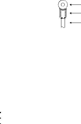
(a)The cables to be connected to the terminal block of the servo amplifier must have crimping terminals provided with insulating tubes to prevent contact with adjacent terminals.
Crimping terminal
Insulating tube
Cable
(b)Use the servo motor side power connector which complies with the EN Standard. The EN Standard compliant power connector sets are available from us as options. (Refer to section 14.1)
(7)Auxiliary equipment and options
(a)The no-fuse breaker and magnetic contactor used should be the EN or IEC standard-compliant products of the models described in section 14.10.
Use a type B (Note) breaker. When it is not used, provide insulation between the servo amplifier and other device by double insulation or reinforced insulation, or install a transformer between the main power supply and servo amplifier.
Note. Type A: AC and pulse detectable Type B: Both AC and DC detectable
(b)The sizes of the cables described in section 14.9 meet the following requirements. To meet the other requirements, follow Table 5 and Appendix C in EN60204-1.
Ambient temperature: 40 (104) [°C (°F)] Sheath: PVC (polyvinyl chloride)
Installed on wall surface or open table tray
(c)Use the EMC filter for noise reduction.
(8)Performing EMC tests
When EMC tests are run on a machine/device into which the servo amplifier has been installed, it must conform to the electromagnetic compatibility (immunity/emission) standards after it has satisfied the operating environment/electrical equipment specifications.
For the other EMC directive guidelines on the servo amplifier, refer to the EMC Installation Guidelines (IB(NA)67310).
A — 9
![]()
CONFORMANCE WITH UL/C-UL STANDARD
(1)Servo amplifiers and servo motors used
Use the servo amplifiers and servo motors which comply with the standard model.
|
Servo amplifier |
:MR-J3-10T to MR-J3-22KT |
|
|
MR-J3-10T1 to MR-J3-40T1 |
||
|
MR-J3-60T4 to MR-J3-22KT4 |
||
|
Servo motor |
:HF-MP |
|
|
HF-KP |
||
|
HF-SP |
(Note) |
|
|
HF-SP |
4 (Note) |
|
|
HC-RP |
||
|
HC-UP |
||
|
HC-LP |
||
|
HA-LP |
(Note) |
|
|
HA-LP |
4 (Note) |
Note. For the latest information of compliance, contact Mitsubishi.
(2)Installation
Install a fan of 100CFM (2.8m3/min) air flow 4[in] (10.16[cm]) above the servo amplifier or provide cooling of at least equivalent capability to ensure that the ambient temperature conforms to the environment conditions (55 or less).
(3)Short circuit rating (SCCR: Short Circuit Current Rating)
Suitable For Use In A Circuit Capable Of Delivering Not More Than 100 kA rms Symmetrical Amperes, 500 Volts Maximum.
(4)Capacitor discharge time
The capacitor discharge time is as listed below. To ensure safety, do not touch the charging section for 15 minutes after power-off.
|
Servo amplifier |
Discharge time |
|
|
[min] |
||
|
MR-J3-10T 20T |
1 |
|
|
MR-J3-40T 60T(4) 10T1 20T1 |
2 |
|
|
MR-J3-70T |
3 |
|
|
MR-J3-40T1 |
4 |
|
|
MR-J3-100T(4) |
5 |
|
|
MR-J3-200T(4) 350T |
9 |
|
|
MR-J3-350T4 500T(4) 700T(4) |
10 |
|
|
MR-J3-11KT(4) |
4 |
|
|
MR-J3-15KT(4) |
6 |
|
|
MR-J3-22KT(4) |
8 |
A — 10

(5)Options and auxiliary equipment
Use UL/C-UL standard-compliant products.
(6)Attachment of a servo motor
For the flange size of the machine side where the servo motor is installed, refer to “CONFORMANCE WITH UL/C-UL STANDARD” in the Servo Motor Instruction Manual (Vol.2).
(7)About wiring protection
For installation in United States, branch circuit protection must be provided, in accordance with the National Electrical Code and any applicable local codes.
For installation in Canada, branch circuit protection must be provided, in accordance with the Canada Electrical Code and any applicable provincial codes.
<<About the manuals>>
This Instruction Manual and the MELSERVO Servo Motor Instruction Manual (Vol.2) are required if you use the General-Purpose AC servo MR-J3-T for the first time. Always purchase them and use the MR-J3-T safely.
Relevant manuals
|
Manual name |
Manual No. |
|
MELSERVO-J3 Series Instructions and Cautions for Safe Use of AC Servos |
IB(NA)0300077 |
|
MELSERVO Servo Motor Instruction Manual (Vol.2) |
SH(NA)030041 |
|
EMC Installation Guidelines |
IB(NA)67310 |
<<About the wires used for wiring>>
Wiring wires mentioned in this instruction manual are selected based on the ambient temperature of 40°C (104 ).
).
A — 11

MEMO
A — 12

CONTENTS
|
1. FUNCTIONS AND CONFIGURATION |
1 — 1 to 1 -36 |
|
1.1 Introduction…………………………………………………………………………………………………………………………….. |
1 — 1 |
|
1.1.1 Features of CC-Link communication functions …………………………………………………………………….. |
1 — 1 |
|
1.1.2 Function block diagram……………………………………………………………………………………………………… |
1 — 2 |
|
1.1.3 System configuration…………………………………………………………………………………………………………. |
1 — 5 |
|
1.2 Servo amplifier standard specifications……………………………………………………………………………………… |
1 — 7 |
|
1.3 |
Function list …………………………………………………………………………………………………………………………… |
1 |
-13 |
|
1.4 |
Model code definition ……………………………………………………………………………………………………………… |
1 |
-15 |
|
1.5 |
Combination with servo motor …………………………………………………………………………………………………. |
1 |
-16 |
|
1.6 |
Structure ……………………………………………………………………………………………………………………………….. |
1 |
-17 |
|
1.6.1 Parts identification ……………………………………………………………………………………………………………. |
1 |
-17 |
|
|
1.6.2 Removal and reinstallation of the front cover………………………………………………………………………. |
1 |
-23 |
|
|
1.7 |
Configuration including auxiliary equipment ……………………………………………………………………………… |
1 |
-26 |
|
1.8 |
Selection of operation method…………………………………………………………………………………………………. |
1 |
-34 |
|
2. INSTALLATION |
2 — 1 to 2 — 4 |
||
|
2.1 |
Installation direction and clearances …………………………………………………………………………………………. |
2 — 1 |
|
|
2.2 |
Keep out foreign materials……………………………………………………………………………………………………….. |
2 — 3 |
|
|
2.3 |
Cable stress …………………………………………………………………………………………………………………………… |
2 — 3 |
|
|
2.4 |
Inspection items ……………………………………………………………………………………………………………………… |
2 — 4 |
|
|
2.5 |
Parts having service lives ………………………………………………………………………………………………………… |
2 — 4 |
|
|
3. CC-LINK COMMUNICATION FUNCTIONS |
3 — 1 to 3 -60 |
||
|
3.1 |
Communication specifications ………………………………………………………………………………………………….. |
3 — 1 |
|
|
3.2 |
System configuration ………………………………………………………………………………………………………………. |
3 — 2 |
|
|
3.2.1 Configuration example ………………………………………………………………………………………………………. |
3 — 2 |
||
|
3.2.2 Wiring method ………………………………………………………………………………………………………………….. |
3 — 3 |
||
|
3.2.3 Station number setting ………………………………………………………………………………………………………. |
3 — 5 |
||
|
3.2.4 Communication baud rate setting……………………………………………………………………………………….. |
3 — 6 |
||
|
3.2.5 Occupied station count setting……………………………………………………………………………………………. |
3 — 6 |
||
|
3.3 |
Functions ……………………………………………………………………………………………………………………………….. |
3 — 7 |
|
|
3.3.1 Function block diagram……………………………………………………………………………………………………… |
3 — 7 |
||
|
3.3.2 Functions …………………………………………………………………………………………………………………………. |
3 — 7 |
||
|
3.4 |
Servo amplifier setting …………………………………………………………………………………………………………….. |
3 — 8 |
|
|
3.5 |
I/O signals (I/O devices) transferred to/from the programmable controller CPU…………………………….. |
3 — 9 |
|
|
3.5.1 I/O signals (I/O devices)…………………………………………………………………………………………………….. |
3 — 9 |
||
|
3.5.2 Detailed explanation of I/O signals …………………………………………………………………………………….. |
3 -12 |
||
|
3.5.3 Monitor codes………………………………………………………………………………………………………………….. |
3 -22 |
||
|
3.5.4 Instruction codes (RWwn+2 RWwn+3) …………………………………………………………………………….. |
3 -23 |
||
|
3.5.5 Respond codes (RWrn+2) ………………………………………………………………………………………………… |
3 -31 |
||
|
3.5.6 Setting the CN6 external input signals ……………………………………………………………………………….. |
3 -32 |
||
|
3.6 |
Data communication timing charts …………………………………………………………………………………………… |
3 -34 |
|
|
3.6.1 Monitor codes………………………………………………………………………………………………………………….. |
3 -34 |
||
|
3.6.2 Instruction codes ……………………………………………………………………………………………………………… |
3 -36 |
||
|
1 |

|
3.6.3 Remote register-based position/speed setting…………………………………………………………………….. |
3 |
-38 |
|
|
3.7 |
Function-by-function programming examples……………………………………………………………………………. |
3 |
-41 |
|
3.7.1 System configuration example…………………………………………………………………………………………… |
3 |
-41 |
|
|
3.7.2 Reading the servo amplifier status …………………………………………………………………………………….. |
3 |
-44 |
|
|
3.7.3 Writing the operation commands……………………………………………………………………………………….. |
3 |
-45 |
|
|
3.7.4 Reading the data……………………………………………………………………………………………………………… |
3 |
-46 |
|
|
3.7.5 Writing the data ……………………………………………………………………………………………………………….. |
3 |
-49 |
|
|
3.7.6 Operation………………………………………………………………………………………………………………………… |
3 |
-52 |
|
|
3.8 |
Continuous operation program example…………………………………………………………………………………… |
3 |
-55 |
|
3.8.1 System configuration example when 1 station is occupied …………………………………………………… |
3 |
-55 |
|
|
3.8.2 Program example when 1 station is occupied …………………………………………………………………….. |
3 |
-56 |
|
|
3.8.3 System configuration example when 2 stations are occupied……………………………………………….. |
3 |
-58 |
|
|
3.8.4 Program example when 2 stations are occupied…………………………………………………………………. |
3 |
-59 |
|
|
4. SIGNALS AND WIRING |
4 — 1 to 4 -54 |
||
|
4.1 |
Input power supply circuit ………………………………………………………………………………………………………… |
4 — 2 |
|
|
4.2 |
I/O signal connection diagram …………………………………………………………………………………………………. |
4 -10 |
|
|
4.3 |
Explanation of power supply system………………………………………………………………………………………… |
4 -11 |
|
|
4.3.1 Signal explanations ………………………………………………………………………………………………………….. |
4 -11 |
||
|
4.3.2 Power-on sequence …………………………………………………………………………………………………………. |
4 -12 |
||
|
4.3.3 CNP1, CNP2, CNP3 wiring method …………………………………………………………………………………… |
4 -14 |
||
|
4.4 |
Connectors and signal arrangements ………………………………………………………………………………………. |
4 -22 |
|
|
4.5 |
Signal (device) explanation……………………………………………………………………………………………………… |
4 -23 |
|
|
4.5.1 I/O devices………………………………………………………………………………………………………………………. |
4 -23 |
||
|
4.5.2 Input signals ……………………………………………………………………………………………………………………. |
4 -26 |
||
|
4.5.3 Output signals………………………………………………………………………………………………………………….. |
4 -26 |
||
|
4.5.4 Power supply…………………………………………………………………………………………………………………… |
4 -27 |
||
|
4.6 |
Detailed description of signals (devices)…………………………………………………………………………………… |
4 -27 |
|
|
4.6.1 Forward rotation start |
reverse rotation start temporary stop/restart……………………………………. |
4 -27 |
|
|
4.6.2 Movement completion |
rough match in position ……………………………………………………………….. |
4 -28 |
|
|
4.6.3 Torque limit……………………………………………………………………………………………………………………… |
4 -30 |
||
|
4.7 |
Alarm occurrence timing chart…………………………………………………………………………………………………. |
4 -31 |
|
|
4.8 |
Interface………………………………………………………………………………………………………………………………… |
4 -32 |
|
|
4.8.1 Internal connection diagram ……………………………………………………………………………………………… |
4 -32 |
||
|
4.8.2 Detailed description of interfaces……………………………………………………………………………………….. |
4 -33 |
||
|
4.8.3 Source I/O interfaces ……………………………………………………………………………………………………….. |
4 -35 |
||
|
4.9 |
Treatment of cable shield external conductor ……………………………………………………………………………. |
4 -36 |
|
|
4.10 Connection of servo amplifier and servo motor ……………………………………………………………………….. |
4 -37 |
||
|
4.10.1 Connection instructions…………………………………………………………………………………………………… |
4 -37 |
||
|
4.10.2 Power supply cable wiring diagrams………………………………………………………………………………… |
4 -38 |
||
|
4.11 Servo motor with an electromagnetic brake…………………………………………………………………………….. |
4 -48 |
||
|
4.11.1 Safety precautions …………………………………………………………………………………………………………. |
4 -48 |
||
|
4.11.2 Timing charts…………………………………………………………………………………………………………………. |
4 -49 |
||
|
4.11.3 Wiring diagrams (HF-MP series HF-KP series servo motor) …………………………………………….. |
4 -52 |
||
|
4.12 Grounding……………………………………………………………………………………………………………………………. |
4 -53 |
2

|
5. OPERATION |
5 — 1 to 5 -60 |
||
|
5.1 Switching power on for the first time …………………………………………………………………………………………. |
5 — 1 |
||
|
5.1.1 Startup procedure……………………………………………………………………………………………………………… |
5 — 1 |
||
|
5.1.2 Wiring check …………………………………………………………………………………………………………………….. |
5 — 2 |
||
|
5.1.3 Surrounding environment…………………………………………………………………………………………………… |
5 — 3 |
||
|
5.2 Startup …………………………………………………………………………………………………………………………………… |
5 — 4 |
||
|
5.2.1 Power on and off procedures……………………………………………………………………………………………… |
5 — 4 |
||
|
5.2.2 Stop…………………………………………………………………………………………………………………………………. |
5 — 4 |
||
|
5.2.3 Test operation…………………………………………………………………………………………………………………… |
5 — 5 |
||
|
5.2.4 Parameter setting……………………………………………………………………………………………………………… |
5 — 6 |
||
|
5.2.5 Point table setting……………………………………………………………………………………………………………… |
5 — 7 |
||
|
5.2.6 Actual operation ……………………………………………………………………………………………………………….. |
5 — 7 |
||
|
5.3 Servo amplifier display…………………………………………………………………………………………………………….. |
5 — 8 |
||
|
5.4 Automatic operation mode………………………………………………………………………………………………………. |
5 |
-10 |
|
|
5.4.1 What is automatic operation mode?…………………………………………………………………………………… |
5 |
-10 |
|
|
5.4.2 Automatic operation using point table ………………………………………………………………………………… |
5 |
-12 |
|
|
5.4.3 Remote register-based position/speed setting…………………………………………………………………….. |
5 |
-22 |
|
|
5.5 Manual operation mode ………………………………………………………………………………………………………….. |
5 |
-28 |
|
|
5.5.1 JOG operation …………………………………………………………………………………………………………………. |
5 |
-28 |
|
|
5.5.2 Manual pulse generator ……………………………………………………………………………………………………. |
5 |
-29 |
|
|
5.6 Manual home position return mode………………………………………………………………………………………….. |
5 |
-31 |
|
|
5.6.1 Outline of home position return………………………………………………………………………………………….. |
5 |
-31 |
|
|
5.6.2 Dog type home position return…………………………………………………………………………………………… |
5 |
-34 |
|
|
5.6.3 Count type home position return ……………………………………………………………………………………….. |
5 |
-36 |
|
|
5.6.4 Data setting type home position return……………………………………………………………………………….. |
5 |
-38 |
|
|
5.6.5 Stopper type home position return …………………………………………………………………………………….. |
5 |
-39 |
|
|
5.6.6 Home position ignorance (servo-on position defined as home position) ………………………………… |
5 |
-41 |
|
|
5.6.7 Dog type rear end reference home position return ………………………………………………………………. |
5 |
-42 |
|
|
5.6.8 Count type front end reference home position return …………………………………………………………… |
5 |
-44 |
|
|
5.6.9 Dog cradle type home position return ………………………………………………………………………………… |
5 |
-46 |
|
|
5.6.10 Dog type first Z-phase reference home position return ………………………………………………………. |
5 |
-48 |
|
|
5.6.11 Dog type front end reference home position return method………………………………………………… |
5 |
-50 |
|
|
5.6.12 Dogless Z-phase reference home position return method ………………………………………………….. |
5 |
-52 |
|
|
5.6.13 Home position return automatic return function…………………………………………………………………. |
5 |
-54 |
|
|
5.6.14 Automatic positioning function to the home position…………………………………………………………… |
5 |
-55 |
|
|
5.7 Roll feed display function in roll feed mode……………………………………………………………………………….. |
5 |
-56 |
|
|
5.8 Absolute position detection system ………………………………………………………………………………………….. |
5 |
-57 |
|
|
6. PARAMETERS |
6 — 1 to 6 -40 |
||
|
6.1 Basic setting parameters (No.PA |
)……………………………………………………………………………………… |
6 — 1 |
|
|
6.1.1 Parameter list …………………………………………………………………………………………………………………… |
6 — 1 |
||
|
6.1.2 Parameter write inhibit ………………………………………………………………………………………………………. |
6 — 2 |
||
|
6.1.3 Selection of command system……………………………………………………………………………………………. |
6 — 3 |
||
|
6.1.4 Selection of regenerative option …………………………………………………………………………………………. |
6 — 3 |
||
|
6.1.5 Using absolute position detection system ……………………………………………………………………………. |
6 — 4 |
||
|
6.1.6 Follow-up for absolute value command system in incremental system…………………………………… |
6 — 4 |
||
|
6.1.7 Feeding function selection …………………………………………………………………………………………………. |
6 — 5 |
3

|
6.1.8 Electronic gear………………………………………………………………………………………………………………….. |
6 — 6 |
|||||
|
6.1.9 Auto tuning ………………………………………………………………………………………………………………………. |
6 — 7 |
|||||
|
6.1.10 In-position range……………………………………………………………………………………………………………… |
6 — 8 |
|||||
|
6.1.11 Torque limit…………………………………………………………………………………………………………………….. |
6 — 9 |
|||||
|
6.1.12 Selection of servo motor rotation direction………………………………………………………………………… |
6 |
-10 |
||||
|
6.1.13 Encoder output pulse ……………………………………………………………………………………………………… |
6 |
-10 |
||||
|
6.2 |
Gain/filter parameters (No. PB |
)………………………………………………………………………………………… |
6 |
-12 |
||
|
6.2.1 Parameter list ………………………………………………………………………………………………………………….. |
6 |
-12 |
||||
|
6.2.2 Detail list …………………………………………………………………………………………………………………………. |
6 |
-13 |
||||
|
6.3 |
Extension setting parameters (No. PC |
) …………………………………………………………………………….. |
6 |
-20 |
||
|
6.3.1 Parameter list ………………………………………………………………………………………………………………….. |
6 |
-20 |
||||
|
6.3.2 Detail list …………………………………………………………………………………………………………………………. |
6 |
-21 |
||||
|
6.3.3 S-pattern acceleration/deceleration……………………………………………………………………………………. |
6 |
-27 |
||||
|
6.3.4 Alarm history clear……………………………………………………………………………………………………………. |
6 |
-27 |
||||
|
6.3.5 Rough match output…………………………………………………………………………………………………………. |
6 |
-27 |
||||
|
6.3.6 Software limit …………………………………………………………………………………………………………………… |
6 |
-28 |
||||
|
6.4 |
I/O setting parameters (No. PD |
)……………………………………………………………………………………….. |
6 |
-29 |
||
|
6.4.1 Parameter list ………………………………………………………………………………………………………………….. |
6 |
-29 |
||||
|
6.4.2 Detail list …………………………………………………………………………………………………………………………. |
6 |
-30 |
||||
|
6.4.3 Stopping method when the forward stroke end (LSP) or reverse stroke end (LSN) is valid……… |
6 |
-38 |
||||
|
6.4.4 Stopping method when a software limit is detected……………………………………………………………… |
6 |
-39 |
||||
|
7. MR Configurator |
7 — 1 to 7 -26 |
|||||
|
7.1 |
Specifications …………………………………………………………………………………………………………………………. |
7 — 1 |
||||
|
7.2 |
System configuration ………………………………………………………………………………………………………………. |
7 — 2 |
||||
|
7.3 |
Station selection……………………………………………………………………………………………………………………… |
7 — 4 |
||||
|
7.4 |
Parameters…………………………………………………………………………………………………………………………….. |
7 — 5 |
||||
|
7.5 |
Point table………………………………………………………………………………………………………………………………. |
7 — 7 |
||||
|
7.6 |
Device assignment method ……………………………………………………………………………………………………… |
7 — 9 |
||||
|
7.7 |
Test operation ……………………………………………………………………………………………………………………….. |
7 |
-13 |
|||
|
7.7.1 Jog operation…………………………………………………………………………………………………………………… |
7 |
-13 |
||||
|
7.7.2 Positioning operation………………………………………………………………………………………………………… |
7 |
-15 |
||||
|
7.7.3 Motor-less operation ………………………………………………………………………………………………………… |
7 |
-18 |
||||
|
7.7.4 Output signal (DO) forced output……………………………………………………………………………………….. |
7 |
-19 |
||||
|
7.7.5 Single-step feed ………………………………………………………………………………………………………………. |
7 |
-20 |
||||
|
7.8 |
Alarm ……………………………………………………………………………………………………………………………………. |
7 |
-23 |
|||
|
7.8.1 Alarm display…………………………………………………………………………………………………………………… |
7 |
-23 |
||||
|
7.8.2 Batch display of data at alarm occurrence ………………………………………………………………………….. |
7 |
-24 |
||||
|
7.8.3 Alarm history……………………………………………………………………………………………………………………. |
7 |
-26 |
||||
|
8. PARAMETER UNIT (MR-PRU03) |
8 — 1 to 8 -20 |
|||||
|
8.1 |
External appearance and key explanations ……………………………………………………………………………….. |
8 — 2 |
||||
|
8.2 |
Specifications …………………………………………………………………………………………………………………………. |
8 — 3 |
||||
|
8.3 |
Outline dimension drawings……………………………………………………………………………………………………… |
8 — 3 |
||||
|
8.4 |
Connection with servo amplifier………………………………………………………………………………………………… |
8 — 4 |
||||
|
8.4.1 Single axis ……………………………………………………………………………………………………………………….. |
8 — 4 |
|||||
|
8.4.2 Multidrop connection …………………………………………………………………………………………………………. |
8 — 5 |
4

|
8.5 Display…………………………………………………………………………………………………………………………………… |
8 — 7 |
|
|
8.5.1 Outline of screen transition ………………………………………………………………………………………………… |
8 — 7 |
|
|
8.5.2 MR-PRU03 parameter unit setting ……………………………………………………………………………………… |
8 — 8 |
|
|
8.5.3 Monitor mode (status display)…………………………………………………………………………………………….. |
8 — 9 |
|
|
8.5.4 Alarm/diagnostic mode …………………………………………………………………………………………………….. |
8 -11 |
|
|
8.5.5 Parameter mode………………………………………………………………………………………………………………. |
8 -13 |
|
|
8.5.6 Point table mode ……………………………………………………………………………………………………………… |
8 -14 |
|
|
8.5.7 Test operation mode ………………………………………………………………………………………………………… |
8 -15 |
|
|
8.6 Error message list ………………………………………………………………………………………………………………….. |
8 -19 |
|
|
9. GENERAL GAIN ADJUSTMENT |
9 — 1 to 9 -12 |
|
|
9.1 Different adjustment methods…………………………………………………………………………………………………… |
9 — 1 |
|
|
9.1.1 Adjustment on a single servo amplifier………………………………………………………………………………… |
9 — 1 |
|
|
9.1.2 Adjustment using MR Configurator……………………………………………………………………………………… |
9 — 2 |
|
|
9.2 Auto tuning …………………………………………………………………………………………………………………………….. |
9 — 3 |
|
|
9.2.1 Auto tuning mode ……………………………………………………………………………………………………………… |
9 — 3 |
|
|
9.2.2 Auto tuning mode operation……………………………………………………………………………………………….. |
9 — 4 |
|
|
9.2.3 Adjustment procedure by auto tuning………………………………………………………………………………….. |
9 — 5 |
|
|
9.2.4 Response level setting in auto tuning mode ………………………………………………………………………… |
9 — 6 |
|
|
9.3 Manual mode 1 (simple manual adjustment)……………………………………………………………………………… |
9 — 7 |
|
|
9.4 Interpolation mode …………………………………………………………………………………………………………………. |
9 -11 |
|
|
9.5 Differences between MELSERVO-J2-Super and MELSERVO-J3 in auto tuning………………………….. |
9 -12 |
|
|
10. SPECIAL ADJUSTMENT FUNCTIONS |
10- 1 to 10-16 |
|
|
10.1 |
Function block diagram…………………………………………………………………………………………………………. |
10- 1 |
|
10.2 |
Adaptive filter …………………………………………………………………………………………………………………….. |
10- 1 |
|
10.3 |
Machine resonance suppression filter…………………………………………………………………………………….. |
10- 4 |
|
10.4 |
Advanced vibration suppression control …………………………………………………………………………………. |
10- 6 |
|
10.5 |
Low-pass filter …………………………………………………………………………………………………………………….. |
10-10 |
|
10.6 |
Gain changing function ………………………………………………………………………………………………………… |
10-10 |
|
10.6.1 Applications ………………………………………………………………………………………………………………….. |
10-10 |
|
|
10.6.2 Function block diagram………………………………………………………………………………………………….. |
10-11 |
|
|
10.6.3 Parameters…………………………………………………………………………………………………………………… |
10-12 |
|
|
10.6.4 Gain changing operation………………………………………………………………………………………………… |
10-14 |
|
|
11. TROUBLESHOOTING |
11- 1 to 11-14 |
|
|
11.1 |
Trouble at start-up………………………………………………………………………………………………………………… |
11- 1 |
|
11.2 |
Operation at error occurrence ……………………………………………………………………………………………….. |
11- 2 |
|
11.3 |
CC-Link communication error………………………………………………………………………………………………… |
11- 2 |
|
11.4 When alarm or warning has occurred …………………………………………………………………………………….. |
11- 3 |
|
|
11.4.1 Alarms and warning list…………………………………………………………………………………………………… |
11- 3 |
|
|
11.4.2 Remedies for alarms………………………………………………………………………………………………………. |
11- 4 |
|
|
11.4.3 Remedies for warnings ………………………………………………………………………………………………….. |
11-11 |
|
|
11.5 |
Point table error…………………………………………………………………………………………………………………… |
11-13 |
5
|
12. OUTLINE DRAWINGS |
12- 1 to 12-12 |
||
|
12.1 |
Servo amplifier …………………………………………………………………………………………………………………….. |
12- 1 |
|
|
12.2 |
Connector…………………………………………………………………………………………………………………………… |
12-10 |
|
|
13. CHARACTERISTICS |
13- 1 to 13-10 |
||
|
13.1 |
Overload protection characteristics ………………………………………………………………………………………… |
13- 1 |
|
|
13.2 |
Power supply equipment capacity and generated loss …………………………………………………………….. |
13- 3 |
|
|
13.3 |
Dynamic brake characteristics……………………………………………………………………………………………….. |
13- 6 |
|
|
13.3.1 Dynamic brake operation………………………………………………………………………………………………… |
13- 6 |
||
|
13.3.2 The dynamic brake at the load inertia moment………………………………………………………………….. |
13- 9 |
||
|
13.4 |
Cable flexing life………………………………………………………………………………………………………………….. |
13-10 |
|
|
13.5 |
Inrush currents at power-on of main circuit and control circuit………………………………………………….. |
13-10 |
|
|
14. OPTIONS AND AUXILIARY EQUIPMENT |
14- 1 to 14-90 |
||
|
14.1 |
Cable/connector sets ……………………………………………………………………………………………………………. |
14- 1 |
|
|
14.1.1 Combinations of cable/connector sets ……………………………………………………………………………… |
14- 2 |
||
|
14.1.2 Encoder cable/connector sets …………………………………………………………………………………………. |
14- 8 |
||
|
14.1.3 Motor power supply cables …………………………………………………………………………………………….. |
14-17 |
||
|
14.1.4 Motor brake cables………………………………………………………………………………………………………… |
14-18 |
||
|
14.2 |
Regenerative options …………………………………………………………………………………………………………… |
14-19 |
|
|
14.3 |
FR-BU2-(H) brake unit…………………………………………………………………………………………………………. |
14-32 |
|
|
14.3.1 Selection………………………………………………………………………………………………………………………. |
14-33 |
||
|
14.3.2 Brake unit parameter setting…………………………………………………………………………………………… |
14-33 |
||
|
14.3.3 Connection example ……………………………………………………………………………………………………… |
14-34 |
||
|
14.3.4 Outline dimension drawings……………………………………………………………………………………………. |
14-41 |
||
|
14.4 |
Power regeneration converter ………………………………………………………………………………………………. |
14-43 |
|
|
14.5 |
Power regeneration common converter…………………………………………………………………………………. |
14-46 |
|
|
14.6 |
External dynamic brake ……………………………………………………………………………………………………….. |
14-54 |
|
|
14.7 |
Battery MR-J3BAT ………………………………………………………………………………………………………………. |
14-59 |
|
|
14.8 |
Heat sink outside mounting attachment (MR-J3ACN)……………………………………………………………… |
14-60 |
|
|
14.9 |
Selection example of wires…………………………………………………………………………………………………… |
14-62 |
|
|
14.10 |
No-fuse breakers, fuses, magnetic contactors ……………………………………………………………………… |
14-68 |
|
|
14.11 |
Power factor improving DC reactor ……………………………………………………………………………………… |
14-69 |
|
|
14.12 |
Power factor improving reactors………………………………………………………………………………………….. |
14-71 |
|
|
14.13 |
Relays (recommended) ……………………………………………………………………………………………………… |
14-73 |
|
|
14.14 |
Surge absorbers (recommended) ……………………………………………………………………………………….. |
14-73 |
|
|
14.15 |
Noise reduction techniques ………………………………………………………………………………………………… |
14-74 |
|
|
14.16 |
Leakage current breaker…………………………………………………………………………………………………….. |
14-81 |
|
|
14.17 |
EMC filter (recommended) …………………………………………………………………………………………………. |
14-83 |
|
|
14.18 |
MR-HDP01 manual pulse generator……………………………………………………………………………………. |
14-88 |
|
|
15. COMMUNICATION FUNCTION |
15- 1 to 15-46 |
||
|
15.1 |
Configuration……………………………………………………………………………………………………………………….. |
15- 1 |
|
|
15.2 |
Communication specifications ……………………………………………………………………………………………….. |
15- 3 |
|
|
15.2.1 Communication overview………………………………………………………………………………………………… |
15- 3 |
||
|
15.2.2 Parameter setting…………………………………………………………………………………………………………… |
15- 4 |
6

|
15.3 Protocol ………………………………………………………………………………………………………………………………. |
15- 5 |
|
|
15.3.1 Transmission data configuration………………………………………………………………………………………. |
15- 5 |
|
|
15.3.2 Character codes…………………………………………………………………………………………………………….. |
15- 6 |
|
|
15.3.3 Error codes ……………………………………………………………………………………………………………………. |
15- 7 |
|
|
15.3.4 Checksum……………………………………………………………………………………………………………………… |
15- 7 |
|
|
15.3.5 Time-out operation …………………………………………………………………………………………………………. |
15- 8 |
|
|
15.3.6 Retry operation………………………………………………………………………………………………………………. |
15- 8 |
|
|
15.3.7 Initialization……………………………………………………………………………………………………………………. |
15- 9 |
|
|
15.3.8 Communication procedure example…………………………………………………………………………………. |
15- 9 |
|
|
15.4 Command and data No. list ………………………………………………………………………………………………….. |
15-10 |
|
|
15.4.1 Read commands …………………………………………………………………………………………………………… |
15-10 |
|
|
15.4.2 Write commands …………………………………………………………………………………………………………… |
15-14 |
|
|
15.5 Detailed explanations of commands ……………………………………………………………………………………… |
15-17 |
|
|
15.5.1 Data processing ……………………………………………………………………………………………………………. |
15-17 |
|
|
15.5.2 Status display ……………………………………………………………………………………………………………….. |
15-19 |
|
|
15.5.3 Parameters…………………………………………………………………………………………………………………… |
15-20 |
|
|
15.5.4 External I/O signal statuses (DIO diagnosis) ……………………………………………………………………. |
15-23 |
|
|
15.5.5 Device ON/OFF…………………………………………………………………………………………………………….. |
15-28 |
|
|
15.5.6 Disable/enable of I/O devices (DIO)………………………………………………………………………………… |
15-29 |
|
|
15.5.7 Input devices ON/OFF (test operation) ……………………………………………………………………………. |
15-30 |
|
|
15.5.8 Test operation mode ……………………………………………………………………………………………………… |
15-31 |
|
|
15.5.9 Alarm history…………………………………………………………………………………………………………………. |
15-37 |
|
|
15.5.10 Current alarm ……………………………………………………………………………………………………………… |
15-38 |
|
|
15.5.11 Point table…………………………………………………………………………………………………………………… |
15-39 |
|
|
15.5.12 Servo amplifier group designation…………………………………………………………………………………. |
15-45 |
|
|
15.5.13 Other commands…………………………………………………………………………………………………………. |
15-46 |
|
|
16. INDEXER POSITIONING OPERATION |
16- 1 to 16-112 |
|
|
16.1 Function………………………………………………………………………………………………………………………………. |
16- 1 |
|
|
16.1.1 Overview……………………………………………………………………………………………………………………….. |
16- 1 |
|
|
16.1.2 Servo amplifier standard specifications (functions only)……………………………………………………… |
16- 1 |
|
|
16.1.3 Function list …………………………………………………………………………………………………………………… |
16- 2 |
|
|
16.2 I/O signals (I/O devices) transferred to/from the programmable controller CPU………………………….. |
16- 3 |
|
|
16.2.1 I/O signals (I/O devices)………………………………………………………………………………………………….. |
16- 3 |
|
|
16.2.2 Detailed explanation of I/O signals …………………………………………………………………………………… |
16- 5 |
|
|
16.2.3 Monitor codes……………………………………………………………………………………………………………….. |
16-14 |
|
|
16.2.4 Instruction codes (RWwn |
2 RWwn 3)……………………………………………………………………….. |
16-15 |
|
16.2.5 Respond codes (RWrn |
2) ……………………………………………………………………………………………. |
16-22 |
|
16.3 Signal…………………………………………………………………………………………………………………………………. |
16-23 |
|
|
16.3.1 Signal (device) explanation…………………………………………………………………………………………….. |
16-23 |
|
|
16.3.2 Detailed description of signals (devices)………………………………………………………………………….. |
16-26 |
|
|
16.4 Switching power on for the first time ……………………………………………………………………………………… |
16-29 |
|
|
16.4.1 Startup procedure …………………………………………………………………………………………………………. |
16-29 |
|
|
16.4.2 Wiring check…………………………………………………………………………………………………………………. |
16-30 |
|
|
16.4.3 Surrounding environment ………………………………………………………………………………………………. |
16-31 |
|
|
16.5 Startup ……………………………………………………………………………………………………………………………….. |
16-32 |
|
|
16.5.1 Power on and off procedures………………………………………………………………………………………….. |
16-32 |
|
|
16.5.2 Stop……………………………………………………………………………………………………………………………… |
16-32 |
7
![]()
|
16.5.3 Test operation ………………………………………………………………………………………………………………. |
16-33 |
||
|
16.5.4 Parameter setting………………………………………………………………………………………………………….. |
16-34 |
||
|
16.5.5 Point table setting………………………………………………………………………………………………………….. |
16-35 |
||
|
16.5.6 Actual operation ……………………………………………………………………………………………………………. |
16-35 |
||
|
16.6 Servo amplifier display…………………………………………………………………………………………………………. |
16-36 |
||
|
16.7 Automatic operation mode……………………………………………………………………………………………………. |
16-38 |
||
|
16.7.1 What is automatic operation mode?………………………………………………………………………………… |
16-38 |
||
|
16.7.2 Automatic operation mode 1 (Rotation direction specifying indexer)…………………………………… |
16-39 |
||
|
16.7.3 Automatic operation mode 2 (Shortest rotating indexer) ……………………………………………………. |
16-49 |
||
|
16.8 Manual operation mode……………………………………………………………………………………………………….. |
16-58 |
||
|
16.8.1 Indexer JOG operation…………………………………………………………………………………………………… |
16-58 |
||
|
16.8.2 JOG operation ………………………………………………………………………………………………………………. |
16-60 |
||
|
16.9 Home position return mode ………………………………………………………………………………………………….. |
16-61 |
||
|
16.9.1 Outline of home position return……………………………………………………………………………………….. |
16-61 |
||
|
16.9.2 Torque limit changing dog type home position return………………………………………………………… |
16-63 |
||
|
16.9.3 Torque limit changing data setting type home position return…………………………………………….. |
16-65 |
||
|
16.9.4 Home position return automatic return function………………………………………………………………… |
16-66 |
||
|
16.10 Absolute position detection system……………………………………………………………………………………… |
16-67 |
||
|
16.11 Parameters……………………………………………………………………………………………………………………….. |
16-70 |
||
|
16.11.1 Basic setting parameters (No.PA |
)…………………………………………………………………………… |
16-70 |
|
|
16.11.2 Gain/filter parameters (No.PB |
)……………………………………………………………………………….. |
16-79 |
|
|
16.11.3 Extension setting parameters (No.PC |
) ……………………………………………………………………. |
16-87 |
|
|
16.11.4 I/O setting parameters (No.PD |
)…………………………………………………………………………… |
16-93 |
|
|
16.12 TROUBLESHOOTING ………………………………………………………………………………………………………. |
16-98 |
||
|
16.12.1 Trouble at start-up……………………………………………………………………………………………………….. |
16-98 |
||
|
16.12.2 Operation at error occurrence……………………………………………………………………………………….. |
16-99 |
||
|
16.12.3 CC-Link communication error……………………………………………………………………………………….. |
16-99 |
||
|
16.12.4 When alarm or warning has occurred ………………………………………………………………………….. |
16-100 |
||
|
16.12.5 Point table error…………………………………………………………………………………………………………. |
16-112 |
||
|
APPENDIX |
App.- 1 to App.-30 |
||
|
App. 1 Parameter list…………………………………………………………………………………………………………………. |
App.- 1 |
||
|
App. 2 Signal layout recording paper ………………………………………………………………………………………….. |
App.- 3 |
||
|
App. 3 Twin type connector: outline drawing for 721-2105/026-000(WAGO) ………………………………….. |
App.- 4 |
||
|
App. 4 Change of connector sets to the RoHS compatible products………………………………………………. |
App.- 5 |
||
|
App. 5 MR-J3-200T-RT servo amplifier……………………………………………………………………………………….. |
App.- 6 |
||
|
App. 6 Selection example of servo motor power cable ………………………………………………………………… |
App.-10 |
||
|
App. 7 Parameter list………………………………………………………………………………………………………………… |
App.-11 |
||
|
App. 8 Program example with MELSEC-A series programmable controllers |
|||
|
(point table positioning operation) |
……………..App.-13 |
8

1.FUNCTIONS AND CONFIGURATION
1.FUNCTIONS AND CONFIGURATION
1.1 Introduction
The MR-J3- T CC-Link compatible servo amplifier can support the CC-Link communication functions. Up to 42 axes of servo amplifiers can be controlled/monitored from the programmable controller side.
As the servo, it has the function to perform positioning operation by merely setting the position data (target positions), servo motor speeds, acceleration and deceleration time constants, etc. to point tables as if setting them in parameters. The servo amplifier is the most appropriate to configure a program-free, simple positioning system or to simplify a system, for example.
There are 31 points of point tables to be used when 1 station is occupied and 255 points when 2 stations are occupied.
All servo motors are equipped with an absolute position encoder as standard. An absolute position detection system can be configured by merely adding a battery to the servo amplifier. Once the home position has been set, home position return is not required at power on, alarm occurrence, etc.
The MR-J3-T is made easier to use and higher in function by using it with the MR Configurator.
1.1.1 Features of CC-Link communication functions
(1)Fast communication
Fast communication can be made by cyclic transmission of not only bit data but also word data.
(a)The highest communication speed is 10Mbps.
(b)The broadcast polling system ensures as high as 3.9ms to 6.7ms even at the maximum link scan (10Mbps).
(2)Variable communication speed/distance system
Selection of speed/distance allows use in a wide range of areas from a system requiring high speed to a system requiring long distance.
(3)System fault prevention (station separating function)
Because of connection in the bus system, any remote or local station that has become faulty due to poweroff or the like does not affect communications with normal remote and local stations.
In addition, use of the two-piece terminal block allows the unit to be changed during data link.
(4)Factory Automation compatible
As the remote device stations of CC-Link, the servo amplifiers share a link system and can be controlled/monitored with programmable controller user programs.
From the programmable controller side, the running speed, acceleration/deceleration time constant and other settings of servo motors can be changed/checked and the servo motors started and stopped.
1 — 1
1. FUNCTIONS AND CONFIGURATION
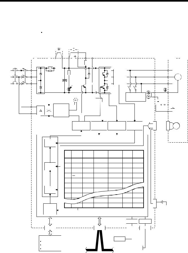
1.1.2 Function block diagram
The function block diagram of this servo is shown below.
(1) MR-J3-350T or less MR-J3-200T4 or less
|
Power factor |
Regenerative |
|||||
|
improving DC |
||||||
|
reactor |
option |
|||||
|
Servo amplifier P1 |
P2 |
P( ) C D N( |
) |
Servo motor |
||
|
Diode |
Relay |
(Note 1) |
|||||
|
NFB |
MC |
stack |
U |
U |
|||
|
L1 |
|||||||
|
(Note 2) |
L2 |
Current |
V |
V |
|||
|
Power |
M |
||||||
|
detector |
|||||||
|
supply |
L3 |
CHARGE |
W |
W |
|||
|
Regene- |
|||||||
|
lamp |
rative |
||||||
|
TR |
|
(Note 4) Cooling fan |
Dynamic |
|||||||||||||||||
|
L11 |
Control |
brake |
RA |
Electro- |
||||||||||||||
|
circuit |
24VDC B1 |
magnetic |
||||||||||||||||
|
L21 |
power |
B2 |
brake |
|||||||||||||||
|
supply |
||||||||||||||||||
Model adaptive control
|
Base |
Voltage |
Overcurrent |
Current |
CN2 |
||||||
|
amplifier |
detection |
protection |
detection |
|||||||
|
Encoder |
||||||||||
|
Current |
|||||||||
|
control |
Point table |
||||||||
|
No. |
Position |
Speed |
Acceleration |
Deceleration |
Dwell |
Auxiliary |
|||
|
data |
time |
time |
|||||||
|
constant |
constant |
||||||||
|
1 |
1000 |
1000 |
80 |
80 |
0 |
0 |
|||
|
Speed |
2 |
2000 |
2000 |
100 |
100 |
0 |
0 |
||
|
control |
3 |
4000 |
2000 |
70 |
60 |
500 |
1 |
||
|
4 |
500 |
2000 |
60 |
70 |
1000 |
1 |
|||
|
5 |
1000 |
2000 |
80 |
80 |
0 |
0 |
|||
|
Position |
6 |
2000 |
1000 |
80 |
80 |
0 |
0 |
||
|
7 |
1000 |
1000 |
80 |
80 |
0 |
0 |
|||
|
control |
|||||||||
|
8 |
1000 |
1000 |
100 |
100 |
0 |
0 |
MR-J3BAT |
||
|
(Note 3) |
1000 |
1000 |
100 |
100 |
0 |
0 |
|||
|
CN4 |
|||||||||
|
Position |
255 |
2000 |
2000 |
80 |
80 |
0 |
0 |
||
|
command |
Optional battery |
||||||||
|
creation |
(for absolute position |
||||||||
|
detection system) |
|||||||||
|
USB |
RS-422 |
|
CN6 |
CN1 |
Personal |
CN5 |
CN3 |
|||||
|
computer |
|||||||||
|
DI/O Control |
USB |
||||||||
|
Servo on |
Controller |
||||||||
|
Start |
CC-Link |
||||||||
|
RS-422 |
|||||||||
|
Failure, etc |
|||||||||
Note 1. The built-in regenerative resistor is not provided for the MR-J3-10T (1).
2.For 1-phase 200 to 230VAC, connect the power supply to L1, L2 and leave L3 open.
There is no L3 for 1-phase 100 to 120VAC power supply. Refer to section 1.2 for the power supply specification.
3.For the case when 2 stations are occupied. When 1 station is occupied, the point table ends at No.31.
4.Servo amplifiers MR-J3-70T or greater have a cooling fan.
1 — 2
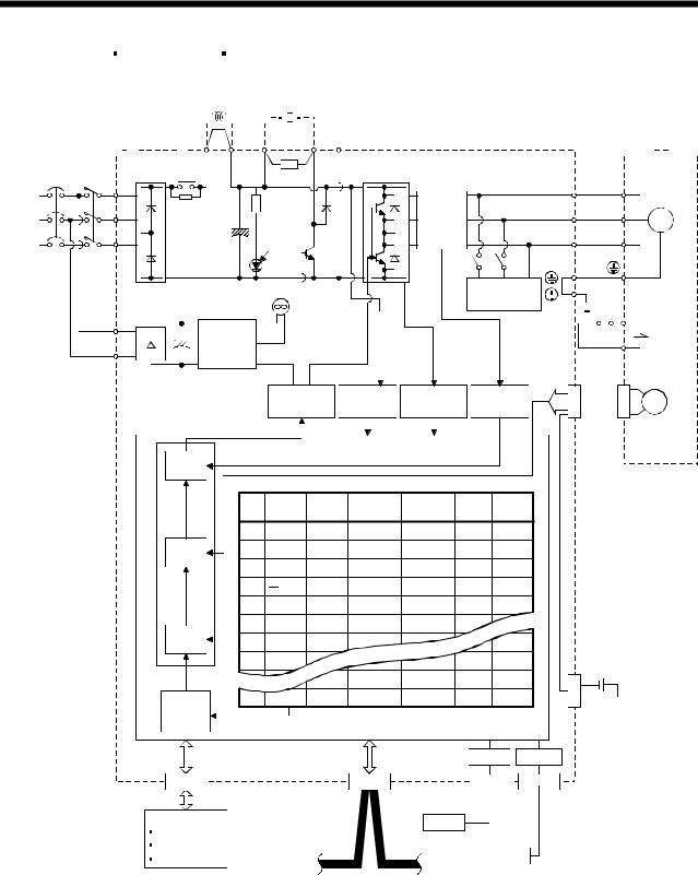
1. FUNCTIONS AND CONFIGURATION
|
(2) MR-J3-350T4 MR-J3-500T(4) |
MR-J3-700T(4) |
||
|
Power factor |
|||
|
improving DC Regenerative |
|||
|
reactor |
option |
||
|
C N |
|||
|
Servo amplifier P1 |
P2 P |
Servo motor |
|
Diode |
Relay |
||||||
|
NFB |
MC |
stack |
U |
U |
|||
|
L1 |
|||||||
|
(Note 1) |
L2 |
Current |
V |
V |
|||
|
Power |
M |
||||||
|
detector |
|||||||
|
supply |
L3 |
CHARGE |
W |
W |
|||
|
Regene- |
|||||||
|
lamp |
rative |
||||||
|
TR |
|
Cooling fan |
Dynamic |
|||||||||||||||||||
|
L11 |
Control |
brake |
RA |
Electro- |
||||||||||||||||
|
circuit |
24VDC B1 |
magnetic |
||||||||||||||||||
|
L21 |
power |
B2 |
brake |
|||||||||||||||||
|
supply |
||||||||||||||||||||
Model adaptive control
|
Base |
Voltage |
Overcurrent |
Current |
CN2 |
||||||
|
amplifier |
detection |
protection |
detection |
|||||||
|
Encoder |
||||||||||
|
Current |
|||||||||
|
control |
Point table |
||||||||
|
No. |
Position |
Speed |
Acceleration |
Deceleration |
Dwell |
Auxiliary |
|||
|
data |
time |
time |
|||||||
|
constant |
constant |
||||||||
|
1 |
1000 |
1000 |
80 |
80 |
0 |
0 |
|||
|
Speed |
2 |
2000 |
2000 |
100 |
100 |
0 |
0 |
||
|
control |
3 |
4000 |
2000 |
70 |
60 |
500 |
1 |
||
|
4 |
500 |
2000 |
60 |
70 |
1000 |
1 |
|||
|
5 |
1000 |
2000 |
80 |
80 |
0 |
0 |
|||
|
Position |
6 |
2000 |
1000 |
80 |
80 |
0 |
0 |
||
|
7 |
1000 |
1000 |
80 |
80 |
0 |
0 |
|||
|
control |
|||||||||
|
8 |
1000 |
1000 |
100 |
100 |
0 |
0 |
MR-J3BAT |
||
|
(Note 2) |
1000 |
1000 |
100 |
100 |
0 |
0 |
|||
|
CN4 |
|||||||||
|
Position |
255 |
2000 |
2000 |
80 |
80 |
0 |
0 |
||
|
command |
Optional battery |
||||||||
|
creation |
(for absolute position |
||||||||
|
detection system) |
|||||||||
|
USB |
RS-422 |
CN6
DI/O Control
Servo on
Start
Failure, etc
Note 1. Refer to section 1.2 for the power supply specification.
|
CN1 |
Personal |
CN5 |
CN3 |
|
|
computer |
||||
|
USB |
Controller
CC-Link
RS-422
2. For the case when 2 stations are occupied. When 1 station is occupied, the point table ends at No.31.
1 — 3
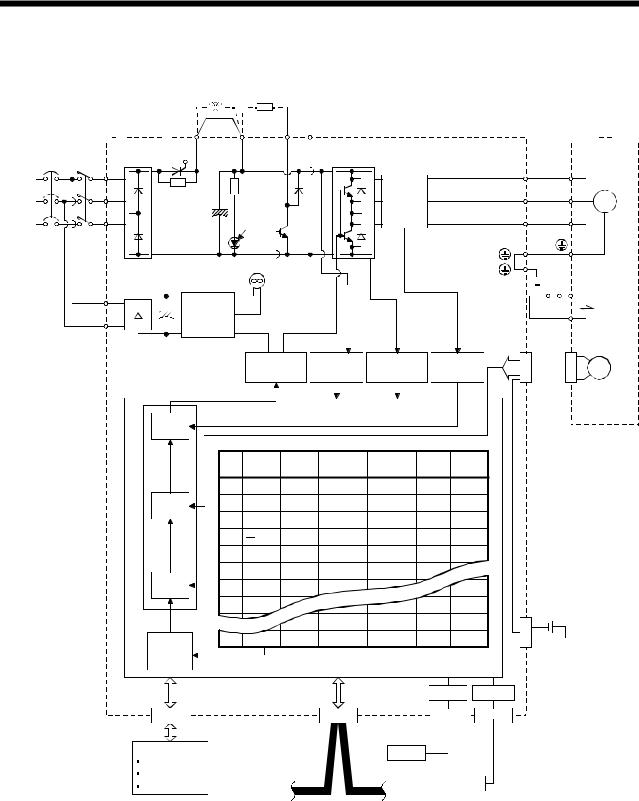
1. FUNCTIONS AND CONFIGURATION
(3) MR-J3-11KT(4) to 22KT(4)
Power factor
improving DC Regenerative reactor option
|
Servo amplifier |
P1 |
P |
C |
N |
Servo motor |
||||
|
Diode Thyristor |
|||||||||
|
NFB |
MC |
stack |
U |
U |
|||||
|
L1 |
|||||||||
|
(Note 1) |
L2 |
Current |
V |
V |
|||||
|
Power |
M |
||||||||
|
detector |
|||||||||
|
supply |
L3 |
CHARGE |
W |
W |
|||||
|
Regene- |
|||||||||
|
lamp |
rative |
||||||||
|
TR |
|||||||||
|
Cooling fan |
|
L11 |
Control |
RA |
Electro- |
|||||||||||||
|
circuit |
24VDC B1 |
magnetic |
||||||||||||||
|
L21 |
power |
B2 |
brake |
|||||||||||||
|
supply |
||||||||||||||||
Model adaptive control
|
Base |
Voltage |
Overcurrent |
Current |
CN2 |
||||||
|
amplifier |
detection |
protection |
detection |
|||||||
|
Encoder |
||||||||||
|
Current |
|||||||||
|
control |
Point table |
||||||||
|
No. |
Position |
Speed |
Acceleration |
Deceleration |
Dwell |
Auxiliary |
|||
|
data |
time |
time |
|||||||
|
constant |
constant |
||||||||
|
1 |
1000 |
1000 |
80 |
80 |
0 |
0 |
|||
|
Speed |
2 |
2000 |
2000 |
100 |
100 |
0 |
0 |
||
|
control |
3 |
4000 |
2000 |
70 |
60 |
500 |
1 |
||
|
4 |
500 |
2000 |
60 |
70 |
1000 |
1 |
|||
|
5 |
1000 |
2000 |
80 |
80 |
0 |
0 |
|||
|
Position |
6 |
2000 |
1000 |
80 |
80 |
0 |
0 |
||
|
7 |
1000 |
1000 |
80 |
80 |
0 |
0 |
|||
|
control |
|||||||||
|
8 |
1000 |
1000 |
100 |
100 |
0 |
0 |
MR-J3BAT |
||
|
(Note 2) |
1000 |
1000 |
100 |
100 |
0 |
0 |
|||
|
CN4 |
|||||||||
|
Position |
255 |
2000 |
2000 |
80 |
80 |
0 |
0 |
||
|
command |
Optional battery |
||||||||
|
creation |
(for absolute position |
||||||||
|
detection system) |
|||||||||
|
USB |
RS-422 |
CN6
DI/O Control
Servo on
Start
Failure, etc
Note 1. Refer to section 1.2 for the power supply specification.
|
CN1 |
Personal |
CN5 |
CN3 |
|
|
computer |
||||
|
USB |
Controller
CC-Link
RS-422
2. For the case when 2 stations are occupied. When 1 station is occupied, the point table ends at No.31.
1 — 4
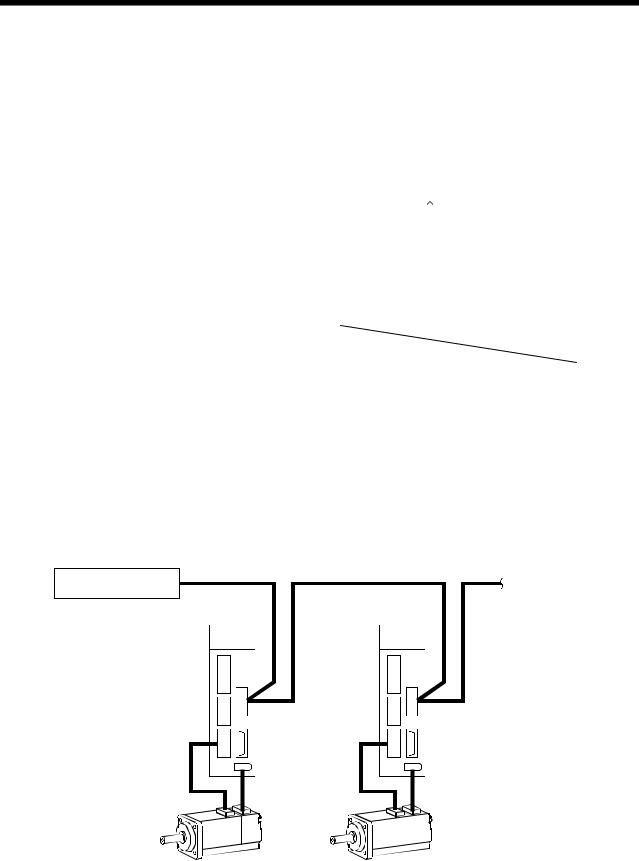
1. FUNCTIONS AND CONFIGURATION
1.1.3 System configuration
This section provides operations using this servo.
Use of CC-Link enables you to freely configure any system from a single-axis system to an up to 42-axis system.
Set the following values to the point table.
|
Name |
Setting range |
Unit |
||
|
0.001[mm] |
||||
|
Position data |
999999 to 999999 |
0.01[mm] |
||
|
0.1[mm] |
||||
|
1[mm] |
||||
|
Servo motor speed |
0 to max. speed |
[r/min] |
||
|
Acceleration time constant |
0 to 20000 |
[ms] |
||
|
Deceleration time constant |
0 to 20000 |
[ms] |
||
|
Dwell |
0 to 20000 |
[ms] |
||
|
Auxiliary function |
0 to 3 |
|||
|
(Refer to section 4.2) |
||||
There are 31 points of point tables to be used when 1 station is occupied and 255 points when 2 stations are occupied.
(1)Operation using CC-Link communication functions
(a)Operation
All devices can be controlled by CC-Link communication. Also, each point table setting, point table selection, parameter value change, setting, monitor, servo motor operation and others can be performed.
(b)Configuration
|
Programmable controller |
To the next axis |
|
|
CC-Link master unit |
||
|
Servo amplifier |
Servo amplifier |
|
|
(Axis 1) |
(Axis 2) |
|
CN1 |
CN1 |
||
|
CN6 |
CN6 |
||
|
CNP3 |
CNP3 |
||
|
CN2 |
CN2 |
1 — 5
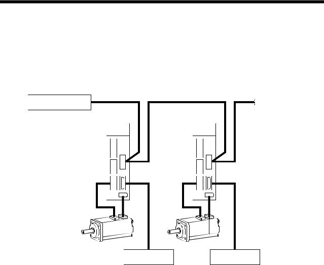
1. FUNCTIONS AND CONFIGURATION
(2)Operation using CC-Link communication functions and external input signals
(a)Operation
Using parameter No.PD06 to PD08 and parameter No.PD12, PD14, input devices can be assigned to the external input devices of CN1A and CN1B. The signals assigned to the external input signals cannot be used with the CC-Link communication functions. Output devices can be used with the CN6 connectors and CC-Link communication functions simultaneously.
(b)Configuration
|
Programmable controller |
To the next axis |
||||
|
CC-Link master unit |
|||||
|
Servo amplifier |
Servo amplifier |
||||
|
(Axis 1) |
(Axis 2) |
||||
|
CN1 |
CN1 |
|
CN6 |
CN6 |
|
CNP3 |
CNP3 |
|
CN2 |
CN2 |
|
External I/O |
External I/O |
|
signal |
signal |
1 — 6
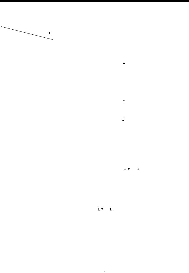
1. FUNCTIONS AND CONFIGURATION
1.2 Servo amplifier standard specifications
(1) 200V class, 100V class
|
Servo amplifier |
|||||||||||||||||||||||
|
MR-J3- |
10T |
20T |
40T |
60T |
70T |
100T |
200T |
350T |
500T |
700T |
11KT |
15KT |
22KT |
10T1 |
20T1 |
40T1 |
|||||||
|
Item |
|||||||||||||||||||||||
|
Voltage/frequency |
3-phase or 1-phase 200 to |
3-phase 200 to 230VAC, 50/60Hz |
1-phase 100V to |
||||||||||||||||||||
|
230VAC, 50/60Hz |
120VAC, 50/60Hz |
||||||||||||||||||||||
|
supply |
|||||||||||||||||||||||
|
230VAC: 170 to 253VAC |
132VAC |
||||||||||||||||||||||
|
Permissible voltage fluctuation |
3-phase or 1-phase 200 to |
3-phase 170 to 253VAC |
1-phase 85 to |
||||||||||||||||||||
|
Power |
Permissible frequency |
Within |
5% |
||||||||||||||||||||
|
fluctuation |
|||||||||||||||||||||||
|
Power supply capacity |
Refer to section 13.2 |
||||||||||||||||||||||
|
Inrush current |
Refer to section 13.5 |
||||||||||||||||||||||
|
Voltage, |
1-phase 200 to 230VAC, 50/60Hz |
1-phase 100 to |
|||||||||||||||||||||
|
frequency |
120VAC, 50/60Hz |
||||||||||||||||||||||
|
Permissible |
1-phase 170 to 253VAC |
1-phase 85 to |
|||||||||||||||||||||
|
voltage fluctuation |
132VAC |
||||||||||||||||||||||
|
Control circuit |
|||||||||||||||||||||||
|
Permissible |
|||||||||||||||||||||||
|
power supply |
|||||||||||||||||||||||
|
frequency |
Within |
5% |
|||||||||||||||||||||
|
fluctuation |
|||||||||||||||||||||||
|
Input |
30W |
45W |
30W |
||||||||||||||||||||
|
Inrush current |
Refer to section 13.5 |
||||||||||||||||||||||
|
Interface power |
Voltage |
24VDC 10% |
|||||||||||||||||||||
|
Power supply |
|||||||||||||||||||||||
|
supply |
(Note 1) 150mA |
||||||||||||||||||||||
|
capacity |
|||||||||||||||||||||||
|
Control System |
Sine-wave PWM control, current control system |
||||||||||||||||||||||
|
Dynamic brake |
Built-in |
External option |
Built-in |
||||||||||||||||||||
|
Overcurrent shut-off, regenerative overvoltage shut-off, overload shut-off (electronic thermal relay), |
|||||||||||||||||||||||
|
Protective functions |
servo motor overheat protection, encoder error protection, regenerative brake error protection, |
||||||||||||||||||||||
|
undervoltage, instantaneous power failure protection, overspeed protection, excessive error |
|||||||||||||||||||||||
|
protection |
|||||||||||||||||||||||
|
Operational |
Positioning by specifying the point table No. (255 points) |
||||||||||||||||||||||
|
specifications |
|||||||||||||||||||||||
|
Point table |
Position command |
Set in point table. 1-point feed length setting range: |
1[ m] to 999.999[mm] |
||||||||||||||||||||
|
input |
|||||||||||||||||||||||
|
number |
|||||||||||||||||||||||
|
Speed command |
Set in point table. Acceleration/deceleration time is set in point table. |
||||||||||||||||||||||
|
input |
|||||||||||||||||||||||
|
input |
S-pattern acceleration/deceleration time constant is set in parameter No.PC13. |
||||||||||||||||||||||
|
system |
|||||||||||||||||||||||
|
System |
Signed absolute value command system, incremental value command system, signed absolute |
||||||||||||||||||||||
|
value command/incremental value command specifying system |
|||||||||||||||||||||||
|
Command |
Operational |
Remote register setting is used for positioning. |
|||||||||||||||||||||
|
Position |
specifications |
||||||||||||||||||||||
|
Position command |
Remote register is used to set position command data. |
||||||||||||||||||||||
|
command |
|||||||||||||||||||||||
|
input |
Feed length input setting range: |
1 m to 999.999m |
|||||||||||||||||||||
|
data input |
|||||||||||||||||||||||
|
Remote register is used to make selection from point table. |
|||||||||||||||||||||||
|
(when 2 |
Speed command |
||||||||||||||||||||||
|
Remote register is used to set speed command data (speed). |
|||||||||||||||||||||||
|
stations are |
input |
||||||||||||||||||||||
|
S-pattern acceleration/deceleration time constant is set in parameter No.PC13. |
|||||||||||||||||||||||
|
occupied) |
|||||||||||||||||||||||
|
System |
Signed absolute value command system, incremental value command system, signed absolute |
||||||||||||||||||||||
|
value command/incremental value command specifying system |
|||||||||||||||||||||||
|
Point table |
Point table number input, position data input system |
||||||||||||||||||||||
|
Automatic |
Positioning operation is performed once in accordance with the position and speed commands. |
||||||||||||||||||||||
|
mode |
|||||||||||||||||||||||
|
operation |
Automatic |
Varied speed operation (2 to 255 speeds), automatic continuous positioning operation (2 to 255 |
|||||||||||||||||||||
|
mode |
continuous |
points) |
|||||||||||||||||||||
|
Operation |
operation |
or through CC-Link communication function. |
|||||||||||||||||||||
|
Manual |
Jog |
Jog operation is performed in accordance with the parameter-set speed command by contact input |
|||||||||||||||||||||
|
operation |
|||||||||||||||||||||||
|
Manual pulse |
Manual feed is made by manual pulse generator. |
||||||||||||||||||||||
|
mode |
|||||||||||||||||||||||
|
generator |
Command pulse multiplication: |
1, 10 or 100 is selected using parameter. |
|||||||||||||||||||||
1 — 7

1. FUNCTIONS AND CONFIGURATION
|
Servo amplifier |
|||||||||||||||||||
|
MR-J3- |
10T |
20T |
40T |
60T |
70T |
100T |
200T |
350T |
500T |
700T |
11KT |
15KT |
22KT |
10T1 |
20T1 |
40T1 |
|||
|
Item |
|||||||||||||||||||
|
Home position return is made starting with Z-phase pulse after passage of proximity dog. |
|||||||||||||||||||
|
Dog type |
Home position address may be set. Home position shift distance may be set. Home position return |
||||||||||||||||||
|
direction may be selected. |
|||||||||||||||||||
|
Automatic at-dog home position return return/automatic stroke return function. |
|||||||||||||||||||
|
Home position return is made by counting encoder pulses after contact with proximity dog. |
|||||||||||||||||||
|
Count type |
Home position address may be set. Home position shift value may be set. Home position return |
||||||||||||||||||
|
direction may be set. |
|||||||||||||||||||
|
Automatic at-dog home position return return/automatic stroke return function. |
|||||||||||||||||||
|
Home position return is made without dog. |
|||||||||||||||||||
|
Data setting type |
Home position may be set at any position by manual operation, etc. Home position address may be |
||||||||||||||||||
|
set. |
|||||||||||||||||||
|
Stopper type |
Home position return is made by pressing machine part against stroke end. |
||||||||||||||||||
|
Home position address may be set. Home position return direction may be set. |
|||||||||||||||||||
|
Home position |
Position where servo-on (RYn0) is switched on is defined as home position. |
||||||||||||||||||
|
ignorance |
Home position address may be set. |
||||||||||||||||||
|
(Servo-on position |
|||||||||||||||||||
|
as home position) |
|||||||||||||||||||
|
Home position return is made with respect to the rear end of a proximity dog. |
|||||||||||||||||||
|
Dog type rear end |
Home position address may be set. Home position shift value may be set. Home position return |
||||||||||||||||||
|
mode |
Home |
reference |
direction may be set. |
||||||||||||||||
|
position |
Automatic at-dog home position return return/automatic stroke return function. |
||||||||||||||||||
|
Operation |
return |
Home position return is made with respect to the front end of a proximity dog. |
|||||||||||||||||
|
mode |
Count type front |
Home position address may be set. Home position shift value may be set. Home position return |
|||||||||||||||||
|
end reference |
direction may be set. |
||||||||||||||||||
|
Automatic at-dog home position return return/automatic stroke return function. |
|||||||||||||||||||
|
Home position return is made with respect to the front end of a proximity dog by the first Z-phase |
|||||||||||||||||||
|
pulse. |
|||||||||||||||||||
|
Dog cradle type |
Home position address may be set. Home position shift value may be set. Home position return |
||||||||||||||||||
|
direction may be set. |
|||||||||||||||||||
|
Automatic at-dog home position return return/automatic stroke return function. |
|||||||||||||||||||
|
Home position return is made with respect to the front end of a proximity dog by the last Z-phase |
|||||||||||||||||||
|
Dog type last |
pulse. |
||||||||||||||||||
|
Home position address may be set. Home position shift value may be set. Home position return |
|||||||||||||||||||
|
Z-phase reference |
|||||||||||||||||||
|
direction may be set. |
|||||||||||||||||||
|
Automatic at-dog home position return return/automatic stroke return function. |
|||||||||||||||||||
|
Home position return is made to the dog front end with respect to the front end of a proximity dog. |
|||||||||||||||||||
|
Dog type front end |
Home position address may be set. Home position shift value may be set. Home position return |
||||||||||||||||||
|
reference |
direction may be set. |
||||||||||||||||||
|
Automatic at-dog home position return return/automatic stroke return function. |
|||||||||||||||||||
|
Dogless |
Home position return is made with respect to the first Z-phase to the Z-phase. |
||||||||||||||||||
|
Home position address may be set. Home position shift value may be set. Home position return |
|||||||||||||||||||
|
Z-phase reference |
|||||||||||||||||||
|
direction may be set. |
|||||||||||||||||||
|
Automatic positioning to home |
High-speed automatic return to a defined home position. |
||||||||||||||||||
|
position |
|||||||||||||||||||
|
Absolute position detection, backlash function |
|||||||||||||||||||
|
Other functions |
Overtravel prevention using external limit switch |
||||||||||||||||||
|
Software stroke limit |
|||||||||||||||||||
|
Structure |
Self-cooled, open |
Force-cooling, open (IP00) |
Self-cooled, open |
||||||||||||||||
|
(IP00) |
(IP00) |
||||||||||||||||||
1 — 8

1. FUNCTIONS AND CONFIGURATION
|
Servo amplifier |
|||||||||||||||||||||||
|
MR-J3- |
10T |
20T |
40T |
60T |
70T |
100T |
200T |
350T |
500T |
700T |
11KT |
15KT |
22KT |
10T1 |
20T1 |
40T1 |
|||||||
|
Item |
|||||||||||||||||||||||
|
In operation |
[ |
] |
(Note 2) 0 to |
55 (non-freezing) |
|||||||||||||||||||
|
Ambient |
[ |
] |
(Note 2) 32 to |
131 (non-freezing) |
|||||||||||||||||||
|
Environment |
temperature |
In storage |
[ |
] |
20 to 65 (non-freezing) |
||||||||||||||||||
|
[ |
] |
4 to |
149 (non-freezing) |
||||||||||||||||||||
|
Ambient |
In operation |
90%RH or less (non-condensing) |
|||||||||||||||||||||
|
humidity |
In storage |
||||||||||||||||||||||
|
Ambient |
Indoors (no direct sunlight) |
||||||||||||||||||||||
|
Free from corrosive gas, flammable gas, oil mist, dust and dirt |
|||||||||||||||||||||||
|
Altitude |
Max. 1000m above sea level |
||||||||||||||||||||||
|
Vibration |
5.9 [m/s2] or less |
||||||||||||||||||||||
|
Mass |
[kg] |
0.8 |
0.8 |
1.0 |
1.0 |
1.4 |
1.4 |
2.1 |
2.3 |
4.6 |
6.2 |
18 |
18 |
19 |
0.8 |
0.8 |
1.0 |
||||||
|
[lb] |
1.76 |
1.76 |
2.21 |
2.21 |
3.09 |
3.09 |
4.63 |
5.07 |
10.1 |
13.7 |
39.7 |
39.7 |
41.9 |
1.76 |
1.76 |
2.21 |
|||||||
Note 1. 150mA is the value applicable when all I/O signals are used. The current capacity can be decreased by reducing the number of I/O points.
2. When closely mounting the servo amplifier of 3.5kW or less, operate them at the ambient temperatures of 0 to 45 (32 to 113
 ) or at 75% or smaller effective load ratio.
1 — 9
![]()
1. FUNCTIONS AND CONFIGURATION
(2) 400V class
|
Servo amplifier |
|||
|
MR-J3- |
|||
|
Item |
|||
|
supply |
Voltage/frequency |
||
|
Permissible voltage fluctuation |
|||
|
Permissible frequency |
|||
|
Power |
fluctuation |
||
|
Power supply capacity |
|||
|
Inrush current |
|||
|
Voltage, |
|||
|
frequency |
|||
|
Permissible |
|||
|
Control circuit |
voltage fluctuation |
||
|
Permissible |
|||
|
power supply |
|||
|
frequency |
|||
|
fluctuation |
|||
|
Input |
|||
|
Inrush current |
|||
|
Interface power |
Voltage |
||
|
supply |
Power supply |
||
|
capacity |
|||
|
Control System |
|||
|
Dynamic brake |
|||
|
Protective functions |
|||
|
Operational |
|||
|
specifications |
|||
|
Point table |
Position command |
||
|
input |
|||
|
number |
|||
|
Speed command |
|||
|
input |
|||
|
input |
|||
|
system |
|||
|
System |
|||
|
Command |
|||
|
Operational |
|||
|
Position |
specifications |
||
|
Position command |
|||
|
command |
|||
|
input |
|||
|
data input |
|||
|
(when 2 |
Speed command |
||
|
stations are |
input |
||
|
occupied) |
|||
|
System |
|||
|
Automatic |
Point table |
||
|
mode |
|||
|
operation |
Automatic |
||
|
mode |
continuous |
||
|
Operation |
operation |
||
|
Manual |
Jog |
||
|
operation |
Manual pulse |
||
|
mode |
|||
|
generator |
|||
|
60T4 |
100T4 |
200T4 |
350T4 |
500T4 |
700T4 |
11KT4 |
15KT4 |
22KT4 |
3-phase 380 to 480VAC, 50/60Hz
3-phase 323 to 528VAC
Within  5%
5%
Refer to section 13.2
Refer to section 13.5
1-phase 380 to 480VAC, 50/60Hz
1-phase 323 to 528VAC
|
Within |
5% |
|
|
30W |
45W |
|
|
Refer to section 13.5 |
||
|
24VDC |
10% |
(Note) 150mA
Sine-wave PWM control, current control system
Built-in External option
Overcurrent shut-off, regenerative overvoltage shut-off, overload shut-off (electronic thermal relay), servo motor overheat protection, encoder error protection, regenerative brake error protection, undervoltage, instantaneous power failure protection, overspeed protection, excessive error protection
Positioning by specifying the point table No. (255 points)
Set in point table. 1-point feed length setting range:  1[
1[ m] to
m] to  999.999[mm]
Set in point table. Acceleration/deceleration time is set in point table. S-pattern acceleration/deceleration time constant is set in parameter No.PC13.
Signed absolute value command system, incremental value command system, signed absolute value command/incremental value command specifying system
Remote register setting is used for positioning.
Remote register is used to set position command data.
Feed length input setting range:  1
1 m to
m to  999.999m
Remote register is used to make selection from point table. Remote register is used to set speed command data (speed).
S-pattern acceleration/deceleration time constant is set in parameter No.PC13.
Signed absolute value command system, incremental value command system, signed absolute value command/incremental value command specifying system
Point table number input, position data input system
Positioning operation is performed once in accordance with the position and speed commands.
Varied speed operation (2 to 255 speeds), automatic continuous positioning operation (2 to 255 points)
Jog operation is performed in accordance with the parameter-set speed command by contact input or through CC-Link communication function.
Manual feed is made by manual pulse generator.
Command pulse multiplication:  1,
1,  10 or
10 or  100 is selected using parameter.
1 — 10

1. FUNCTIONS AND CONFIGURATION
|
Servo amplifier |
||||||||||||||||||
|
MR-J3- |
60T4 |
100T4 |
200T4 |
350T4 |
500T4 |
700T4 |
11KT4 |
15KT4 |
22KT4 |
|||||||||
|
Item |
||||||||||||||||||
|
Home position return is made starting with Z-phase pulse after passage of proximity dog. |
||||||||||||||||||
|
Dog type |
Home position address may be set. Home position shift distance may be set. Home position return |
|||||||||||||||||
|
direction may be selected. |
||||||||||||||||||
|
Automatic at-dog home position return return/automatic stroke return function. |
||||||||||||||||||
|
Home position return is made by counting encoder pulses after contact with proximity dog. |
||||||||||||||||||
|
Count type |
Home position address may be set. Home position shift value may be set. Home position return |
|||||||||||||||||
|
direction may be set. |
||||||||||||||||||
|
Automatic at-dog home position return return/automatic stroke return function. |
||||||||||||||||||
|
Home position return is made without dog. |
||||||||||||||||||
|
Data setting type |
Home position may be set at any position by manual operation, etc. Home position address may be |
|||||||||||||||||
|
set. |
||||||||||||||||||
|
Stopper type |
Home position return is made by pressing machine part against stroke end. |
|||||||||||||||||
|
Home position address may be set. Home position return direction may be set. |
||||||||||||||||||
|
Home position |
Position where servo-on (RYn0) is switched on is defined as home position. |
|||||||||||||||||
|
ignorance |
Home position address may be set. |
|||||||||||||||||
|
(Servo-on position |
||||||||||||||||||
|
as home position) |
||||||||||||||||||
|
Home position return is made with respect to the rear end of a proximity dog. |
||||||||||||||||||
|
Home |
Dog type rear end |
Home position address may be set. Home position shift value may be set. Home position return |
||||||||||||||||
|
mode |
reference |
direction may be set. |
||||||||||||||||
|
position |
Automatic at-dog home position return return/automatic stroke return function. |
|||||||||||||||||
|
Operation |
return |
Home position return is made with respect to the front end of a proximity dog. |
||||||||||||||||
|
mode |
Count type front |
Home position address may be set. Home position shift value may be set. Home position return |
||||||||||||||||
|
end reference |
direction may be set. |
|||||||||||||||||
|
Automatic at-dog home position return return/automatic stroke return function. |
||||||||||||||||||
|
Home position return is made with respect to the front end of a proximity dog by the first Z-phase |
||||||||||||||||||
|
pulse. |
||||||||||||||||||
|
Dog cradle type |
Home position address may be set. Home position shift value may be set. Home position return |
|||||||||||||||||
|
direction may be set. |
||||||||||||||||||
|
Automatic at-dog home position return return/automatic stroke return function. |
||||||||||||||||||
|
Home position return is made with respect to the front end of a proximity dog by the last Z-phase |
||||||||||||||||||
|
Dog type last |
pulse. |
|||||||||||||||||
|
Home position address may be set. Home position shift value may be set. Home position return |
||||||||||||||||||
|
Z-phase reference |
||||||||||||||||||
|
direction may be set. |
||||||||||||||||||
|
Automatic at-dog home position return return/automatic stroke return function. |
||||||||||||||||||
|
Home position return is made to the dog front end with respect to the front end of a proximity dog. |
||||||||||||||||||
|
Dog type front end |
Home position address may be set. Home position shift value may be set. Home position return |
|||||||||||||||||
|
reference |
direction may be set. |
|||||||||||||||||
|
Automatic at-dog home position return return/automatic stroke return function. |
||||||||||||||||||
|
Dogless |
Home position return is made with respect to the first Z-phase to the Z-phase. |
|||||||||||||||||
|
Home position address may be set. Home position shift value may be set. Home position return |
||||||||||||||||||
|
Z-phase reference |
||||||||||||||||||
|
direction may be set. |
||||||||||||||||||
|
Automatic positioning to home |
High-speed automatic return to a defined home position. |
|||||||||||||||||
|
position |
||||||||||||||||||
|
Absolute position detection, backlash function |
||||||||||||||||||
|
Other functions |
Overtravel prevention using external limit switch |
|||||||||||||||||
|
Software stroke limit |
||||||||||||||||||
|
Structure |
Self-cooled, open |
Force-cooling, open (IP00) |
||||||||||||||||
|
(IP00) |
||||||||||||||||||
1 — 11

1. FUNCTIONS AND CONFIGURATION
|
Servo amplifier |
|||||||||||||||||
|
MR-J3- |
60T4 |
100T4 |
200T4 |
350T4 |
500T4 |
700T4 |
11KT4 |
15KT4 |
22KT4 |
||||||||
|
Item |
|||||||||||||||||
|
In operation |
[ |
] |
0 to |
55 (non-freezing) |
|||||||||||||
|
Ambient |
[ |
] |
32 to |
131 (non-freezing) |
|||||||||||||
|
Environment |
temperature |
In storage |
[ |
] |
20 to |
65 (non-freezing) |
|||||||||||
|
[ |
] |
||||||||||||||||
|
Indoors (no direct sunlight) |
|||||||||||||||||
|
4 to |
149 (non-freezing) |
||||||||||||||||
|
Ambient |
In operation |
90%RH or less (non-condensing) |
|||||||||||||||
|
humidity |
In storage |
||||||||||||||||
|
Ambient |
Free from corrosive gas, flammable gas, oil mist, dust and dirt |
||||||||||||||||
|
Altitude |
Max. 1000m above sea level |
||||||||||||||||
|
Vibration |
5.9 [m/s2] or less |
||||||||||||||||
|
Mass |
[kg] |
1.7 |
1.7 |
2.1 |
4.6 |
4.6 |
6.2 |
18 |
18 |
19 |
|||||||
|
[lb] |
3.75 |
3.75 |
4.63 |
10.1 |
10.1 |
13.7 |
39.7 |
39.7 |
41.9 |
||||||||
|
Note. 150mA is the value applicable |
when all I/O signals are used. The current capacity can be decreased by reducing the number of |
||||||||||||||||
|
I/O points. |
1 — 12

1. FUNCTIONS AND CONFIGURATION
1.3 Function list
The following table lists the functions of this servo. For details of the functions, refer to the reference field.
|
Function |
Description |
Reference |
|
|
Select the required ones from among 31 preset point tables and perform |
|||
|
Positioning by automatic |
operation in accordance with the set values. |
Section 5.4 |
|
|
operation |
Use the external input signal or communication function to choose the point |
||
|
tables. |
|||
|
Varied speed operation |
Servo motor speed can be varied continuously until the preset moving |
Section 5.4.2 |
|
|
distance is reached. (Max. set speeds: 255 speeds) |
(4)(b) |
||
|
Automatic continuous positioning |
By merely choosing one point table and starting operation, positioning can |
Section 5.4.2 (4) |
|
|
operation |
be executed continuously in accordance with several point tables. |
||
|
Dog type, count type, data setting type, stopper type, home position |
|||
|
Home position return |
ignorance, dog type rear end reference, count type front end reference, dog |
Section 5.6 |
|
|
cradle type |
|||
|
High-resolution encoder |
High-resolution encoder of 262144 pulses/rev is used as a servo motor |
||
|
encoder. |
|||
|
Absolute position detection |
By merely setting the home position once, home position return need not be |
Section 5.7 |
|
|
system |
done at each power on. |
||
|
Gain changing function |
You can switch between gains during rotation and gains during stop or use |
Section 10.6 |
|
|
an input device to change gains during operation. |
|||
|
Advanced vibration suppression |
This function suppresses vibration at the arm end or residual vibration. |
Section 10.4 |
|
|
control |
|||
|
Adaptive filter |
Servo amplifier detects mechanical resonance and sets filter characteristics |
Section 10.2 |
|
|
automatically to suppress mechanical vibration. |
|||
|
Low-pass filter |
Suppresses high-frequency resonance which occurs as servo system |
Section 10.5 |
|
|
response is increased. |
|||
|
Analyzes the frequency characteristic of the mechanical system by simply |
|||
|
Machine analyzer function |
connecting a MR Configurator installed personal computer and servo |
||
|
amplifier. |
|||
|
MR Configurator is necessary for this function. |
|||
|
Can simulate machine motions on a personal computer screen on the basis |
|||
|
Machine simulation |
of the machine analyzer results. |
||
|
MR Configurator is necessary for this function. |
|||
|
Personal computer changes gains automatically and searches for |
|||
|
Gain search function |
overshoot-free gains in a short time. |
||
|
MR Configurator is necessary for this function. |
|||
|
Slight vibration suppression |
Suppresses vibration of 1 pulse produced at a servo motor stop. |
Parameters No. |
|
|
control |
PB24 |
||
|
The electronic gear is used to make adjustment so that the servo amplifier |
|||
|
Electronic gear |
setting matches the machine moving distance. Also, changing the electronic |
Parameter No. |
|
|
gear value allows the machine to be moved at any multiplication ratio to the |
PA06, PA07 |
||
|
moving distance using the servo amplifier. |
|||
|
Auto tuning |
Automatically adjusts the gain to optimum value if load applied to the servo |
Section 9.2 |
|
|
motor shaft varies. |
|||
|
S-pattern |
Acceleration/deceleration can be made smoothly. |
Parameters No. |
|
|
acceleration/deceleration time |
|||
|
PC13 |
|||
|
constant |
|||
|
Regenerative option |
Used when the built-in regenerative resistor of the servo amplifier does not |
Section 14.2 |
|
|
have sufficient regenerative capability for the regenerative power generated. |
|||
|
Used when the regenerative option cannot provide enough regenerative |
|||
|
Brake unit |
power. |
Section 14.3 |
|
|
Can be used with the servo amplifier of 5kW or more. |
|||
|
Used when the regenerative option cannot provide enough regenerative |
|||
|
Regeneration converter |
power. |
Section 14.4 |
|
|
Can be used with the servo amplifier of 5kW or more. |
|||
|
Alarm history clear |
Alarm history is cleared. |
Parameter No. |
|
|
PC18 |
|||
1 — 13

1. FUNCTIONS AND CONFIGURATION
|
Function |
Description |
Reference |
||
|
I/O signal selection (Device |
Any input device such as servo-on (SON) can be assigned to any pin of CN6 |
Parameter No. |
||
|
connector. |
PD06 to PD08 |
|||
|
setting) |
||||
|
PD12 |
PD14 |
|||
|
Torque limit |
Servo motor-torque is limited. |
Section 4.6.3 |
||
|
Section 6.1.11 |
||||
|
Output signal (DO) forced output |
Output signal can be forced on/off independently of the servo status. |
Section 7.7.4 |
||
|
Use this function for output signal wiring check, etc. |
Section 8.5.7(4) |
|||
|
JOG operation positioning operation DO forced output single — step |
Section 7.7 |
|||
|
Test operation mode |
feed. |
|||
|
Section 8.5.7 |
||||
|
MR Configurator is necessary for this function. |
||||
|
Limit switch |
The servo motor travel region can be limited using the forward rotation |
|||
|
stroke end (LSP)/reverse rotation stroke end (LSN). |
||||
|
Software limit |
The travel region is limited using parameters in terms of address. |
Section 6.3.6 |
||
|
The function similar to that of a limit switch is limited by parameter. |
||||
1 — 14

1. FUNCTIONS AND CONFIGURATION
1.4 Model code definition
(1) Rating plate
|
MITSUBISHI |
AC SERVO |
Model |
||||||||||
|
MODEL |
MR-J3-10T |
Capacity |
||||||||||
|
POWER : 100W |
Applicable power supply |
|||||||||||
|
INPUT |
: 0.9A 3PH+1PH200-230V 50Hz |
|||||||||||
|
3PH+1PH200-230V 60Hz |
||||||||||||
|
1.3A 1PH 200-230V 50/60Hz |
Rated output current |
|||||||||||
|
OUTPUT : 170V 0-360Hz 1.1A |
||||||||||||
|
SERIAL |
: A34230001 |
Serial number |
||||||||||
|
PASSED |
||||||||||||
MITSUBISHI ELECTRIC CORPORATION
MADE IN JAPAN
MR-J3-100T(4) or less
 With no regenerative resistor Symbol Description
Indicates a servo amplifier of 11k to 22kW
-PX that does not use a regenerative resistor as standard accessory.
|
Power supply |
||||||||||||||||||||
|
Symbol |
Description |
|||||||||||||||||||
|
(Note 1) |
3-phase or 1-phase 200 |
Rating plate |
||||||||||||||||||
|
None |
to 230VAC |
|||||||||||||||||||
|
(Note 2) |
1-phase 100 to 120VAC |
|||||||||||||||||||
|
1 |
MR-J3-350T |
|||||||||||||||||||
|
4 |
3-phase 380 to 480VAC |
|||||||||||||||||||
|
Note 1. 1-phase 200V to 230V is |
||||||||||||||||||||
|
supported by 750W or less. |
||||||||||||||||||||
|
2. 1-phase 100V to 120V is |
||||||||||||||||||||
|
supported by 400W or less. |
||||||||||||||||||||
|
Built-in positioning function |
||||||||||||||||||||
|
Rated output |
||||||||||||||||||||
|
Symbol |
Rated |
|||||||||||||||||||
|
output [kW] |
||||||||||||||||||||
|
10 |
0.1 |
|||||||||||||||||||
|
20 |
0.2 |
|||||||||||||||||||
|
Rating plate |
||||||||||||||||||||
|
40 |
0.4 |
|||||||||||||||||||
|
60 |
0.6 |
|||||||||||||||||||
|
70 |
0.75 |
MR-J3-700T(4) |
||||||||||||||||||
|
100 |
1 |
|||||||||||||||||||
200 2
350 3.5
500 5
700 7
11K 11
15K 15
22K 22
MR-J3-200T(4)
Rating plate
MR-J3-350T4 500T(4)
Rating plate 
MR-J3-11KT(4) to 22KT(4)
Rating plate
Rating plate
1 — 15

1. FUNCTIONS AND CONFIGURATION
1.5 Combination with servo motor
The following table lists combinations of servo amplifiers and servo motors. The same combinations apply to the servo motors with an electromagnetic brakes and the servo motors with a reduction gear.
Servo motors
|
Servo amplifier |
HF-MP |
HF-KP |
HF-SP |
HC-RP |
HC-UP |
HC-LP |
|||
|
2000r/min |
|||||||||
|
1000r/min |
|||||||||
|
MR-J3-10T (1) |
053 |
13 |
053 |
13 |
|||||
|
MR-J3-20T (1) |
23 |
23 |
|||||||
|
MR-J3-40T (1) |
43 |
43 |
|||||||
|
MR-J3-60T |
51 |
52 |
52 |
||||||
|
MR-J3-70T |
73 |
73 |
72 |
||||||
|
MR-J3-100T |
81 |
102 |
102 |
||||||
|
MR-J3-200T |
121 |
201 |
152 202 |
103 153 |
152 |
152 |
|||
|
MR-J3-350T |
301 |
352 |
203 |
202 |
202 |
||||
|
MR-J3-500T |
421 |
502 |
353 503 |
352 502 |
302 |
||||
|
MR-J3-700T |
702 |
||||||||
|
MR-J3-11KT |
|||||||||
|
MR-J3-15KT |
|||||||||
|
MR-J3-22KT |
|
Servo motors |
||||
|
Servo amplifier |
HA-LP |
|||
|
1000r/min |
1500r/min |
2000r/min |
||
|
MR-J3-500T |
502 |
|||
|
MR-J3-700T |
601 |
701M |
702 |
|
|
MR-J3-11KT |
801 |
12K1 |
11K1M |
11K2 |
|
MR-J3-15KT |
15K1 |
15K1M |
15K2 |
|
|
MR-J3-22KT |
20K1 |
25K1 |
22K1M |
22K2 |
Servo motors
|
Servo amplifier |
HF-SP |
HA-LP |
||||
|
1000r/min |
1500r/min |
2000r/min |
||||
|
MR-J3-60T4 |
524 |
|||||
|
MR-J3-100T4 |
1024 |
|||||
|
MR-J3-200T4 |
1524 |
2024 |
||||
|
MR-J3-350T4 |
3524 |
|||||
|
MR-J3-500T4 |
5024 |
|||||
|
MR-J3-700T4 |
7024 |
6014 |
701M4 |
|||
|
MR-J3-11KT4 |
8014 |
12K14 |
11K1M4 |
11K24 |
||
|
MR-J3-15KT4 |
15K14 |
15K1M4 |
15K24 |
|||
|
MR-J3-22KT4 |
20K14 |
22K1M4 |
22K24 |
1 — 16

1. FUNCTIONS AND CONFIGURATION
1.6 Structure
1.6.1 Parts identification
(1) MR-J3-100T or less
|
4 |
5 |
6 |
||||||||||||||
|
3 |
7 |
|||||||||||||||
|
2 |
8 |
|||||||||||||||
|
1 |
0 |
9 |
||||||||||||||
|
4 |
5 |
6 |
4 |
5 |
6 |
|||||||||||
|
3 |
7 |
3 |
7 |
|||||||||||||
|
2 |
8 |
2 |
8 |
|||||||||||||
|
1 |
0 |
9 |
1 |
0 |
9 |
|||||||||||
Fixed part (2 places)
Name/Application
Display
The 3-digit, seven-segment LED shows the servo status and alarm number.
Baud rate switch (MODE)
MODE
|
4 |
5 |
6 |
Select the CC-Link communication baud rate. |
|
2 |
|||
|
3 |
7 |
||
|
8 |
|||
|
1 |
0 |
9 |
|
Station number switches (STATION NO.) Set the station number of the servo amplifier.
X10 STATION NO. X1
|
4 |
5 |
6 |
4 |
5 |
6 |
|
3 |
7 |
3 |
7 |
||
|
2 |
8 |
2 |
8 |
||
|
1 |
0 |
9 |
1 |
0 |
9 |
|
Set the one place. |
|||||
Set the ten place.
Occupied station count switch (SW1)
SW1
Set the number of occupied stations.
Main circuit power supply connector (CNP1) Used to connect the input power supply.
Communication alarm display section Indicates alarms in CC-Link communication.
USB communication connector (CN5)
Used to connect the personal computer.
CC-Link connector (CN1)
Wire the CC-Link cable.
Control circuit connector (CNP2)
Used to connect the control circuit power supply/ regenerative option.
I/O signal connector (CN6)
Used to connect digital I/O signals.
Servo motor power connector (CNP3)
Used to connect the servo motor.
Encoder connector (CN2)
Used to connect the servo motor encoder.
Battery connector (CN4)
Used to connect the battery for absolute position data backup.
Charge lamp
Lit to indicate that the main circuit is charged. While this lamp is lit, do not reconnect the cables.
Battery holder
Contains the battery for absolute position data backup.
Rating plate
Protective earth (PE) terminal ( )
)
Ground terminal.
1 — 17
Detailed explanation
Section 5.3
Chapter 11
Section 3.2.4
Section 3.2.3
Section 3.2.5
Section 11.3
Chapter 7
Chapter 7
Chapter 8
Chapter 15
Section 3.2.2
Section 4.1
Section 4.3
Section 12.1
Section 14.2
Section 4.2
Section 4.4
Section 4.1
Section 4.3
Section 12.1
Section 4.10
Section 14.1
Section 5.8
Section 14.7
Section 5.8
Section 1.4
Section 4.1
Section 4.3
Section 12.1

1. FUNCTIONS AND CONFIGURATION
(2) MR-J3-200T(4) or less
7 8
Name/Application
Display
The 3-digit, seven-segment LED shows the servo status and alarm number.
Baud rate switch (MODE)
MODE
|
4 |
5 |
6 |
Select the CC-Link communication baud rate. |
|
2 |
|||
|
3 |
7 |
||
|
8 |
|||
|
1 |
0 |
9 |
|
Station number switches (STATION NO.) Set the station number of the servo amplifier.
X10 STATION NO. X1
|
4 |
5 |
6 |
4 |
5 |
6 |
|
3 |
7 |
3 |
7 |
||
|
2 |
8 |
2 |
8 |
||
|
1 |
0 |
9 |
1 |
0 |
9 |
|
Set the one place. |
|||||
Set the ten place.
Occupied station count switch (SW1)
SW1
Set the number of occupied stations.
Cooling fan
Fixed part (3 places)
Main circuit power supply connector (CNP1)
Used to connect the input power supply.
Communication alarm display section
Indicates alarms in CC-Link communication.
|
USB communication connector (CN5) |
|
|
(Note) |
Used to connect the personal computer. |
CC-Link connector (CN1)
Wire the CC-Link cable.
I/O signal connector (CN6)
Used to connect digital I/O signals.
Encoder connector (CN2)
Used to connect the servo motor encoder.
Battery connector (CN4)
Used to connect the battery for absolute position data backup.
Control circuit connector (CNP2)
Used to connect the control circuit power supply/ regenerative option.
Servo motor power connector (CNP3)
Used to connect the servo motor.
Battery holder
Contains the battery for absolute position data backup.
Charge lamp
Lit to indicate that the main circuit is charged. While this lamp is lit, do not reconnect the cables.
Protective earth (PE) terminal ( )
)
Ground terminal.
Rating plate
Detailed explanation
Section 5.3
Chapter 11
Section 3.2.4
Section 3.2.3
Section 3.2.5
Section 11.3
Chapter 7
Chapter 7
Chapter 8
Chapter 15
Section 3.2.2
Section 4.2
Section 4.4
Section 4.10
Section 14.1
Section 5.8
Section 14.7
Section 4.1
Section 4.3
Section 12.1
Section 14.2
Section 4.1
Section 4.3
Section 12.1
Section 5.8
Section 4.1
Section 4.3
Section 12.1
Section 1.4
Note. Connectors (CNP1, CNP2, and CNP3) and appearance of MR-J3-200T servo amplifier have been changed from January 2008 production. Model name of the existing servo amplifier is changed to MR-J3-200T-RT. For MR-J3-200T-RT, refer to appendix 5.
1 — 18

1. FUNCTIONS AND CONFIGURATION
(3) MR-J3-350T
|
4 |
5 |
6 |
|||
|
3 |
7 |
||||
|
2 |
8 |
||||
|
1 |
0 |
9 |
|||
|
4 |
5 |
6 |
4 |
5 |
6 |
|
3 |
7 |
3 |
7 |
||
|
2 |
8 |
2 |
8 |
||
|
1 |
0 |
9 |
1 |
0 |
9 |
Cooling fan
Fixed part (3 places)
|
Name/Application |
Detailed |
|||||||||||||||
|
explanation |
||||||||||||||||
|
Display |
Section 5.3 |
|||||||||||||||
|
The 3-digit, seven-segment LED shows the servo |
||||||||||||||||
|
Chapter 11 |
||||||||||||||||
|
status and alarm number. |
||||||||||||||||
|
Baud rate switch (MODE) |
||||||||||||||||
|
3 |
MODE |
Section 3.2.4 |
||||||||||||||
|
5 |
7 |
|||||||||||||||
|
4 |
6 |
Select the CC-Link communication baud rate. |
||||||||||||||
|
2 |
8 |
|||||||||||||||
|
1 |
0 |
9 |
||||||||||||||
|
Station number switches (STATION NO.) |
||||||||||||||||
|
Set the station number of the servo amplifier. |
||||||||||||||||
|
X10 STATION NO. X1 |
||||||||||||||||
|
4 |
5 |
6 |
4 |
5 |
6 |
Section 3.2.3 |
||||||||||
|
2 |
2 |
|||||||||||||||
|
3 |
7 |
3 |
7 |
|||||||||||||
|
8 |
8 |
|||||||||||||||
|
1 |
0 |
9 |
1 |
0 |
9 |
Set the one place. |
||||||||||
|
Set the ten place. |
||||||||||||||||
|
Occupied station count switch (SW1) |
||||||||||||||||
|
SW1 |
Section 3.2.5 |
|||||||||||||||
|
Set the number of occupied stations. |
||||||||||||||||
|
Main circuit power supply connector (CNP1) |
||||||||||||||||
|
Used to connect the input power supply. |
||||||||||||||||
|
Communication alarm display section |
||||||||||||||||
|
Indicates alarms in CC-Link communication. |
||||||||||||||||
|
Section 11.3 |
||||||||||||||||
|
USB communication connector (CN5) |
Chapter 7 |
|||||||||||||||
|
Used to connect the personal computer. |
||||||||||||||||
|
Chapter 7 |
||||||||||||||||
|
Chapter 8 |
||||||||||||||||
|
Chapter 15 |
||||||||||||||||
|
CC-Link connector (CN1) |
Section 3.2.2 |
|||||||||||||||
|
Wire the CC-Link cable. |
||||||||||||||||
|
Servo motor power connector (CNP3) |
Section 4.1 |
|||||||||||||||
|
Used to connect the servo motor. |
Section 4.3 |
|||||||||||||||
|
Section 12.1 |
||||||||||||||||
|
I/O signal connector (CN6) |
Section 4.2 |
|||||||||||||||
|
Used to connect digital I/O signals. |
Section 4.4 |
|||||||||||||||
|
Encoder connector (CN2) |
Section 4.10 |
|||||||||||||||
|
Used to connect the servo motor encoder. |
Section 14.1 |
|||||||||||||||
|
Battery connector (CN4) |
Section 5.8 |
|||||||||||||||
|
Used to connect the battery for absolute position data |
||||||||||||||||
|
Section 14.7 |
||||||||||||||||
|
backup. |
||||||||||||||||
|
Control circuit connector (CNP2) |
Section 4.1 |
|||||||||||||||
|
Used to connect the control circuit power supply/ |
Section 4.3 |
|||||||||||||||
|
regenerative option. |
Section 12.1 |
|||||||||||||||
|
Section 14.2 |
||||||||||||||||
|
Battery holder |
Section 5.8 |
|||||||||||||||
|
Contains the battery for absolute position data backup. |
||||||||||||||||
|
Charge lamp |
||||||||||||||||
|
Lit to indicate that the main circuit is charged. While |
||||||||||||||||
|
this lamp is lit, do not reconnect the cables. |
||||||||||||||||
|
Protective earth (PE) terminal ( |
) |
Section 4.1 |
||||||||||||||
|
Ground terminal. |
Section 4.3 |
|||||||||||||||
|
Section 12.1 |
||||||||||||||||
|
Rating plate |
Section 1.4 |
|||||||||||||||
1 — 19
![]()
1. FUNCTIONS AND CONFIGURATION
(4) MR-J3-350T4 MR-J3-500T(4)
POINT
The servo amplifier is shown without the front cover. For removal of the front cover, refer to section 1.6.2.
|
4 |
5 |
6 |
|||
|
3 |
7 |
||||
|
2 |
8 |
||||
|
1 |
0 |
9 |
|||
|
4 |
5 |
6 |
4 |
5 |
6 |
|
3 |
7 |
3 |
7 |
||
|
2 |
8 |
2 |
8 |
||
|
1 |
0 |
9 |
1 |
0 |
9 |
Cooling fan
Fixed part (4 places)
Name/Application
Display
The 3-digit, seven-segment LED shows the servo status and alarm number.
Baud rate switch (MODE)
MODE
|
4 |
5 |
6 |
Select the CC-Link communication baud rate. |
|
3 |
7 |
||
|
2 |
8 |
||
|
1 |
0 |
9 |
|
Station number switches (STATION NO.) Set the station number of the servo amplifier.
X10 STATION NO. X1
|
4 |
5 |
6 |
4 |
5 |
6 |
|
3 |
7 |
3 |
7 |
||
|
2 |
8 |
2 |
8 |
||
|
1 |
0 |
9 |
1 |
0 |
9 |
|
Set the one place. |
|||||
Set the ten place.
Occupied station count switch (SW1)
SW1
Set the number of occupied stations.
Communication alarm display section Indicates alarms in CC-Link communication.
USB communication connector (CN5)
Used to connect the personal computer.
CC-Link connector (CN1)
Wire the CC-Link cable.
I/O signal connector (CN6)
Used to connect digital I/O signals.
Battery holder
Contains the battery for absolute position data backup.
Encoder connector (CN2)
Used to connect the servo motor encoder.
Battery connector (CN4)
Used to connect the battery for absolute position data backup.
DC reactor terminal block (TE3)
Used to connect the DC reactor.
Charge lamp
Lit to indicate that the main circuit is charged. While this lamp is lit, do not reconnect the cables.
Main circuit terminal block (TE1)
Used to connect the input power supply and servo motor.
Control circuit terminal block (TE2)
Used to connect the control circuit power supply.
Protective earth (PE) terminal ( )
)
Ground terminal.
Rating plate
Detailed explanation
Section 5.3
Chapter 11
Section 3.2.4
Section 3.2.3
Section 3.2.5
Section 11.3
Chapter 7
Chapter 7
Chapter 8
Chapter 15
Section 3.2.2
Section 4.2
Section 4.4
Section 5.8
Section 4.10
Section 14.1
Section 5.8
Section 14.7
Section 4.1
Section 4.3
Section 12.1
Section 14.11
Section 4.1
Section 4.3
Section 12.1
Section 1.4
1 — 20

1. FUNCTIONS AND CONFIGURATION
(5) MR-J3-700T(4)
POINT
The servo amplifier is shown without the front cover. For removal of the front cover, refer to section 1.6.2.
|
4 |
5 |
6 |
|||
|
3 |
7 |
||||
|
2 |
8 |
||||
|
1 |
0 |
9 |
|||
|
4 |
5 |
6 |
4 |
5 |
6 |
|
3 |
7 |
3 |
7 |
||
|
2 |
8 |
2 |
8 |
||
|
1 |
0 |
9 |
1 |
0 |
9 |
Cooling fan
|
Name/Application |
Detailed |
||||||||||||||||||||||||
|
explanation |
|||||||||||||||||||||||||
|
Display |
Section 5.3 |
||||||||||||||||||||||||
|
The 3-digit, seven-segment LED shows the servo |
|||||||||||||||||||||||||
|
Chapter 11 |
|||||||||||||||||||||||||
|
status and alarm number. |
|||||||||||||||||||||||||
|
Baud rate switch (MODE) |
|||||||||||||||||||||||||
|
3 |
MODE |
Section 3.2.4 |
|||||||||||||||||||||||
|
5 |
7 |
||||||||||||||||||||||||
|
4 |
6 |
Select the CC-Link communication baud rate. |
|||||||||||||||||||||||
|
2 |
8 |
||||||||||||||||||||||||
|
1 |
0 |
9 |
|||||||||||||||||||||||
|
Station number switches (STATION NO.) |
|||||||||||||||||||||||||
|
Set the station number of the servo amplifier. |
|||||||||||||||||||||||||
|
X10 STATION NO. X1 |
|||||||||||||||||||||||||
|
4 |
5 |
6 |
4 |
5 |
6 |
Section 3.2.3 |
|||||||||||||||||||
|
2 |
2 |
||||||||||||||||||||||||
|
3 |
7 |
3 |
7 |
||||||||||||||||||||||
|
8 |
8 |
||||||||||||||||||||||||
|
1 |
0 |
9 |
1 |
0 |
9 |
Set the one place. |
|||||||||||||||||||
|
Set the ten place. |
|||||||||||||||||||||||||
|
Occupied station count switch (SW1) |
|||||||||||||||||||||||||
|
SW1 |
Section 3.2.5 |
||||||||||||||||||||||||
|
Set the number of occupied stations. |
|||||||||||||||||||||||||
|
Communication alarm display section |
|||||||||||||||||||||||||
|
Indicates alarms in CC-Link communication. |
Section 11.3 |
||||||||||||||||||||||||
|
USB communication connector (CN5) |
Chapter 7 |
||||||||||||||||||||||||
|
Used to connect the personal computer. |
|||||||||||||||||||||||||
|
Chapter 7 |
|||||||||||||||||||||||||
|
Chapter 8 |
|||||||||||||||||||||||||
|
Chapter 15 |
|||||||||||||||||||||||||
|
CC-Link connector (CN1) |
Section 3.2.2 |
||||||||||||||||||||||||
|
Wire the CC-Link cable. |
|||||||||||||||||||||||||
|
I/O signal connector (CN6) |
Section 4.2 |
||||||||||||||||||||||||
|
Used to connect digital I/O signals. |
Section 4.4 |
||||||||||||||||||||||||
|
Battery holder |
Section 5.8 |
||||||||||||||||||||||||
|
Contains the battery for absolute position data backup. |
|||||||||||||||||||||||||
|
Encoder connector (CN2) |
Section 4.10 |
||||||||||||||||||||||||
|
Used to connect the servo motor encoder. |
Section 14.1 |
||||||||||||||||||||||||
|
Battery connector (CN4) |
Section 5.8 |
||||||||||||||||||||||||
|
Used to connect the battery for absolute position data |
|||||||||||||||||||||||||
|
Section 14.7 |
|||||||||||||||||||||||||
|
backup. |
|||||||||||||||||||||||||
|
DC reactor terminal block (TE3) |
Section 4.1 |
||||||||||||||||||||||||
|
Used to connect the DC reactor. |
Section 4.3 |
||||||||||||||||||||||||
|
Section 12.1 |
|||||||||||||||||||||||||
|
Section 14.11 |
|||||||||||||||||||||||||
|
Charge lamp |
|||||||||||||||||||||||||
|
Lit to indicate that the main circuit is charged. While |
|||||||||||||||||||||||||
|
this lamp is lit, do not reconnect the cables. |
|||||||||||||||||||||||||
|
Fixed part |
Control circuit terminal block (TE2) |
||||||||||||||||||||||||
|
Used to connect the control circuit power supply. |
|||||||||||||||||||||||||
|
(4 places) |
Section 4.1 |
||||||||||||||||||||||||
|
Main circuit terminal block (TE1) |
|||||||||||||||||||||||||
|
Section 4.3 |
|||||||||||||||||||||||||
|
Used to connect the input power supply and servo motor. |
|||||||||||||||||||||||||
|
Section 12.1 |
|||||||||||||||||||||||||
|
Protective earth (PE) terminal ( |
) |
||||||||||||||||||||||||
|
Ground terminal. |
|||||||||||||||||||||||||
|
Rating plate |
Section 1.4 |
||||||||||||||||||||||||
1 — 21

1. FUNCTIONS AND CONFIGURATION
(6) MR-J3-11KT(4) to MR-J3-22KT(4)
POINT
The servo amplifier is shown without the front cover. For removal of the front cover, refer to section 1.6.2.
|
4 |
5 |
6 |
|||
|
3 |
7 |
||||
|
2 |
8 |
||||
|
1 |
0 |
9 |
|||
|
4 |
5 |
6 |
4 |
5 |
6 |
|
3 |
7 |
3 |
7 |
||
|
2 |
8 |
2 |
8 |
||
|
1 |
0 |
9 |
1 |
0 |
9 |
|
Fixed part |
Cooling fan |
|||||||||||||||||||||||||||||||||||||||||||||||||||||||||||||||||||
|
(4 places) |
||||||||||||||||||||||||||||||||||||||||||||||||||||||||||||||||||||
Name/Application
Display
The 3-digit, seven-segment LED shows the servo status and alarm number.
Baud rate switch (MODE)
MODE
|
4 |
5 |
6 |
Select the CC-Link communication baud rate. |
|
3 |
7 |
||
|
2 |
8 |
||
|
1 |
0 |
9 |
|
Station number switches (STATION NO.) Set the station number of the servo amplifier.
X10 STATION NO. X1
|
4 |
5 |
6 |
4 |
5 |
6 |
|
3 |
7 |
3 |
7 |
||
|
2 |
8 |
2 |
8 |
||
|
1 |
0 |
9 |
1 |
0 |
9 |
|
Set the one place. |
|||||
Set the ten place.
Occupied station count switch (SW1)
SW1
Set the number of occupied stations.
Communication alarm display section Indicates alarms in CC-Link communication.
USB communication connector (CN5)
Used to connect the personal computer.
CC-Link connector (CN1)
Wire the CC-Link cable.
I/O signal connector (CN6)
Used to connect digital I/O signals.
Encoder connector (CN2)
Used to connect the servo motor encoder.
Battery connector (CN4)
Used to connect the battery for absolute position data backup.
Battery holder
Contains the battery for absolute position data backup.
Rating plate
Protective earth (PE) terminal ( )
)
Ground terminal.
Detailed explanation
Section 5.3
Chapter 11
Section 3.2.4
Section 3.2.3
Section 3.2.5
Section 11.3
Chapter 7
Chapter 7
Chapter 8
Chapter 15
Section 3.2.2
Section 4.2
Section 4.4
Section 4.10
Section 14.1
Section 5.8
Section 14.7
Section 5.8
Section 1.4
Section 4.1
Section 4.3
Section 12.1
Section 14.11
1 — 22

1. FUNCTIONS AND CONFIGURATION
1.6.2 Removal and reinstallation of the front cover
Before removing or installing the front cover, turn off the power and wait for 15 minutes or more until the charge lamp turns off. Then, confirm that the voltage
WARNING between P( ) and N( ) is safe with a voltage tester and others. Otherwise, an electric shock may occur. In addition, always confirm from the front of the servo
amplifier whether the charge lamp is off or not.
(1) For MR-J3-350T4 MR-J3-500T(4) MR-J3-700T(4)
Removal of the front cover
a)
a)
|
Hold the ends of lower side of the front cover with |
Pull up the cover, supporting at point a). |
|
both hands. |
Pull out the front cover to remove.
1 — 23

1. FUNCTIONS AND CONFIGURATION
Reinstallation of the front cover
Front cover setting tab
a)
a)
|
Insert the front cover setting tabs into the sockets of |
Pull up the cover, supporting at point a). |
|
servo amplifier (2 places). |
 Setting tab
Push the setting tabs until they click.
1 — 24

1)Fit the front cover installation hooks on the sockets of body cover ( a) to d) ) to reinstall it.
2)Push the front cover until you hear the clicking noise of the installation hook.
Note 1. The cooling fan cover can be locked with enclosed screws (M4  40).
40).
2.By drilling approximately  4 of a hole on the front cover, the front cover can be locked on the body with an enclosed screw (M4
 14).
14).
1 — 25

1. FUNCTIONS AND CONFIGURATION
1.7 Configuration including auxiliary equipment
POINT
Equipment other than the servo amplifier and servo motor are optional or recommended products.
(1)MR-J3-100T or less
(a) For 3-phase or 1-phase 200V to 230VAC
R S T
(Note 3) Power supply
No-fuse breaker (NFB) or fuse
Magnetic  contactor


 (MC)
(MC) 
|
(Note 2) |
|
|
Line noise |
|
|
filter |
|
|
(FR-BSF01) |
|
|
L1 |
|
|
L2 |
|
|
L3 |
|
|
(Note 2) |
|
|
Power factor |
|
|
improving DC |
P1 |
|
reactor |
|
|
(FR-BEL) |
P2 |
P C
Regenerative option
|
MR Configurator |
Personal |
|
computer |
Servo amplifier
|
CN5 |
CC-Link |
|||||||||||||||||
|
CN3 |
||||||||||||||||||
|
CN1 |
||||||||||||||||||
|
U |
CN6 |
I/O signal |
||||||||||||||||
|
V |
||||||||||||||||||
|
W |
||||||||||||||||||
CN2
CN4
(Note 1) Battery MR-J3BAT
Servo motor
Note 1. The battery (option) is used for the absolute position detection system in the position control mode.
2.The AC reactor can also be used. In this case, the DC reactor cannot be used. When not using DC reactor, short P1 and P2.
3.A 1-phase 200V to 230VAC power supply may be used with the servo amplifier of MR-J3-70T or less.
For 1-phase 200V to 230VAC, connect the power supply to L1 L2 and leave L3 open. Refer to section 1.2 for the power supply specification.
1 — 26

1. FUNCTIONS AND CONFIGURATION
(b) For 1-phase 100V to 120VAC
R S
(Note 3) Power supply
No-fuse breaker (NFB) or fuse
Magnetic contactor (MC)
Power factor improving DC  reactor
 (FR-BEL)


Line noise filter (FR-BSF01) 
L1
L2
P C
Regenerative option
|
MR Configurator |
Personal |
|
|
computer |
||
Servo amplifier
|
(Note 2) |
CN5 |
|
|
CN3 |
||
|
CN1 |
||
|
U |
CN6 |
|
|
V |
||
|
W |
||
|
CN2 |
||
|
CN4 |
||
|
(Note 1) |
||
|
Battery |
||
|
MR-J3BAT |
CC-Link
I/O signal
Servo motor
Note 1. The battery (option) is used for the absolute position detection system in the position control mode.
2.The power factor improving DC reactor cannot be used.
3.Refer to section 1.2 for the power supply specification.
1 — 27

1. FUNCTIONS AND CONFIGURATION
(2) MR-J3-60T4 MR-J3-100T4
R S T
(Note 3) Power supply
No-fuse breaker (NFB) or fuse
Magnetic contactor (MC)
(Note 2)
Line noise filter
(FR-BSF01) 

|
Power factor |
L3 |
|
|
improving DC |
||
|
reactor |
||
|
(FR-BEL-H) |
||
|
P1 |
||
|
P2 |
P C
C
Regenerative option
L11
L21
|
MR Configurator |
Personal |
|
|
computer |
||
Servo amplifier


 CN1
CN1
CN6
I/O signal
CN2
CN4
(Note 1) Battery MR-J3BAT
Servo motor
U V W
Note 1. The battery (option) is used for the absolute position detection system in the position control mode.
2.The AC reactor can also be used. In this case, the DC reactor cannot be used. When not using DC reactor, short P1 and P2.
3.Refer to section 1.2 for the power supply specification.
1 — 28

1. FUNCTIONS AND CONFIGURATION
(3) MR-J3-200T(4)
R S T
(Note 3) Power supply
No-fuse breaker (NFB) or fuse
|
MR Configurator |
Personal |
|||||||||||||||||||||||||||||||||||
|
computer |
||||||||||||||||||||||||||||||||||||
|
Magnetic |
||||||||||||||||||||||||||||||||||||
|
contactor |
||||||||||||||||||||||||||||||||||||
|
(MC) |
||||||||||||||||||||||||||||||||||||
|
Line noise filter |
(Note 2) |
|||||||||||||||||||||||||||||||||||
|
(FR-BSF01) |
Servo amplifier |
|||||||||||||||||||||||||||||||||||
|
(Note 2) |
||||||||||||||||||||||||||||||||||||
|
Power factor |
||||||||||||||||||||||||||||||||||||
|
improving |
L1 |
|||||||||||||||||||||||||||||||||||
|
DC reactor |
||||||||||||||||||||||||||||||||||||
|
L2 |
||||||||||||||||||||||||||||||||||||
|
(FR-BEL/ |
||||||||||||||||||||||||||||||||||||
|
L3 |
||||||||||||||||||||||||||||||||||||
|
FR-BEL-H) |
CN5 |
CC-Link |
||||||||||||||||||||||||||||||||||
|
P1 |
||||||||||||||||||||||||||||||||||||
|
CN3 |
||||||||||||||||||||||||||||||||||||
|
P2 |
Regenerative P |
(Note 4) |
||||||||||||||||||||||||||||||||||
|
L11 |
option |
C |
CN1 |
|||||||||||||||||||||||||||||||||
|
L22 |
CN6 |
I/O signal |
||||||||||||||||||||||||||||||||||
|
CN2 |
||||||||||||||||||||||||||||||||||||
|
CN4 |
||||||||||||||||||||||||||||||||||||
|
(Note 1) |
||||||||||||||||||||||||||||||||||||
|
Battery |
||||||||||||||||||||||||||||||||||||
|
U V W |
MR-J3BAT |
|||||||||||||||||||||||||||||||||||
Servo motor
Note 1. The battery (option) is used for the absolute position detection system in the position control mode.
2.The AC reactor can also be used. In this case, the DC reactor cannot be used. When not using DC reactor, short P1 and P2.
3.Refer to section 1.2 for the power supply specification.
4.Connectors (CNP1, CNP2, and CNP3) and appearance of MR-J3-200T servo amplifier have been changed from January 2008 production. Model name of the existing servo amplifier is changed to MR-J3-200T-RT. For MR-J3-200T-RT, refer to appendix 5.
1 — 29
 Loading…

| Номинальная мощность двигателя, Вт | 1000 | |
| Источник питания | Напряжение/частота | 3-фазы 200-230 V AC, 50/60 Гц |
| Допустимые колебания напряжения | 3-фазы 170-253 V AC | |
| Допустимые колебания частоты | ± 5% | |
| Система управления | Синусоидальное управление скоростью вращения ШИМ/ система управления током | |
| Динамический тормоз | Встроенный | |
| Частотная реакция по скорости | 900 Гц | |
| Защитные функции | Отключение по токовой перегрузке, отключение по перенапряжению регенерации, отключение по перегрузке (перегрев электроники), защита серводвигателя от перегрева, защита от ошибки датчика положения, защита от ошибки регенерации, защита от понижения напряжения/ внезапного пропадания питания, защита от чрезмерной скорости, защита от ошибки превышения. | |
| Режим управления позицией | Максимальная частота входных импульсов | 1 000 000 импульсов в секунду (при использовании дифференциального входа), 200 000 импульсов в секунду (при использовании открытого коллектора) |
| Импульсы обратной связи позиционирования | Разрешение на оборот датчика положения/ серводвигателя (262144 импульса/оборот) | |
| Кратное число командных импульсов | Электронный редуктор: передаточное отношение A/B; A:1-1048576, В:1-1048576, 1/10<А/В<2000 | |
| Настройка ширины завершения позиционирования | от 0 до ±10000 В пост. тока (вход командного импульса) | |
| Ошибка превышения | ± 3 оборотов (режим управления положением) | |
| Вход ограничения вращающего момента | Устанавливается параметрами или внешним аналоговым входом (0-±10 В пост. тока/макс. вращающий момент) | |
| Режим управления скоростью | Диапазон управления скоростью | Аналоговое задание скорости 1:2000, внутреннее задание скорости 1:5000 |
| Диапазон аналогового задания скорости | 0-±10 В пост. тока/номинальная скорость | |
| Уровень колебаний скоростью | ±0,01%, максимум (колебание нагрузки 0-100%) 0%, (колебание питания ±10%) ±0,2%, максимум (окружающая температура 25°С ± 10°С), при использовании внешнего аналогового задания скорости | |
| Ограничение вращающего момента | Устанавливается параметрами или внешним аналоговым входом (0-±10 В пост. тока/макс. вращающий момент) | |
| Параметры управления вращающим моментом | Вход задания вращающего момента | 0-±8 В пост. тока/макс. Вращающий момент (входное полное сопротивление от 10 до 12 кОм) |
| Ограничение скорости | Устанавливается параметрами или внешним аналоговым входом (0-±10 В пост. тока/номинальная скорость) | |
| Структура | Охлаждение вентилятором, открытая (IP00) | |
| Окружающая среда | Окружающая температура | Рабочая: от 0 до 55°С (без замораживания); Хранения: от -20 до 65°С (без замораживания) |
| Окружающая влажность | Рабочая: 90% максимальной относительной влажности (без конденсации); Хранения: 90% максимальной относительной влажности (без конденсации) | |
| Атмосфера | Внутри пульта управления; без агрессивных газов, без агрессивных газов, без масляного тумана, без пыли | |
| Высота над уровнем моря | 1000 м над уровнем моря или ниже | |
| Колебания | 5,9 м/сек2 (0,6 G (ускорения свободного падения)), максимум | |
| Вес [кг] | 1,4 | |
| Размеры (ШхВхГ) | 60х168х185 |
Цена предоставляется по запросу
Документация:
Технический каталог — Семейство MR