Руководство на английском языке по кузовному ремонту автомобилей Mitsubishi Lancer/Lancer Station Wagon 1993 года выпуска.
- Автор: —
- Издательство: Mitsubishi Motors Corp.
- Год издания: 1992
- Страниц: —
- Формат: PDF
- Размер: 25,2 Mb
- Автор: —
- Издательство: Mitsubishi Motors Corp.
- Год издания: 1993-2000
- Страниц: —
- Формат: PDF
- Размер: 33,9 Mb
Сборник схем на английском языке электрооборудования автомобиля Mitsubishi Lancer 1997-2000 годов выпуска.
- Автор: —
- Издательство: Mitsubishi Motors Corp.
- Год издания: 1996-1999
- Страниц: —
- Формат: PDF
- Размер: 5,3 Mb
Сборник схем на английском языке электрооборудования автомобиля Mitsubishi Lancer 2007 года выпуска.
- Автор: —
- Издательство: Mitsubishi Motors Corp.
- Год издания: —
- Страниц: —
- Формат: PDF
- Размер: 99,3 Mb
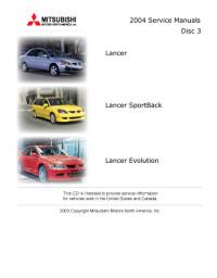
Мультимедийное руководство на английском языке по техническому обслуживанию и ремонту автомобилей Mitsubishi Lancer/Lancer SportBack/Lancer Evolution 2004 года выпуска.
- Автор: —
- Издательство: Mitsubishi Motors
- Год издания: 2003
- Страниц: —
- Формат: —
- Размер: 191,5 Mb
Сборник руководств на английском языке по техническому обслуживанию и ремонту автомобилей Mitsubishi Colt и Mitsubishi Lancer 1992-1996 годов выпуска.
- Автор: —
- Издательство: Mitsubishi Motors Corp.
- Год издания: —
- Страниц: —
- Формат: PDF
- Размер: 41,2 Mb
Сборник руководств на английском языке по техническому обслуживанию и ремонту автомобилей Mitsubishi Colt и Mitsubishi Lancer 1996-2001 годов выпуска.
- Автор: —
- Издательство: Mitsubishi Motors Corp.
- Год издания: 1995-2000
- Страниц: —
- Формат: PDF
- Размер: 26,5 Mb
Руководство на английском языке по техническому обслуживанию и ремонту автомобилей Mitsubishi Lancer/Lancer Wagon 2005 года выпуска. .
- Автор: —
- Издательство: Mitsubishi Motors Corp.
- Год издания: 2004
- Страниц: —
- Формат: PDF
- Размер: 46,3 Mb
Сборник руководств на английском языке по техническому обслуживанию и ремонту автомобиля Mitsubishi Lancer 2006 года выпуска.
- Автор: —
- Издательство: Mitsubishi Motors Corp.
- Год издания: —
- Страниц: —
- Формат: PDF
- Размер: 66,2 Mb
Сборник мультимедийных руководств на английском языке по техническому обслуживанию и ремонту автомобилей Mitsubishi Lancer/Lancer Sportback 2009-2011 годов выпуска
- Автор: —
- Издательство: Mitsubishi Motors
- Год издания: —
- Страниц: —
- Формат: —
- Размер: 4,0 Gb
уководство на английском языке по техническому обслуживанию и ремонту автомобиля Mitsubishi Lancer 2012 года выпуска.
- Автор: —
- Издательство: Mitsubishi Motors Corp.
- Год издания: —
- Страниц: 1253
- Формат: PDF
- Размер: 40,6 Mb

Руководство на английском языке по техническому обслуживанию и ремонту автомобиля Mitsubishi Lancer серий CE/CG. .
- Автор: —
- Издательство: Mitsubishi Motors Corp.
- Год издания: 2001-2002
- Страниц: —
- Формат: PDF
- Размер: 61,5 Mb

Руководство на английском и испанском языках по техническому обслуживанию и ремонту (включая руководство по кузовному ремонту) автомобиля Mitsubishi Lancer 2004 года выпуска.
- Автор: —
- Издательство: Mitsubishi Motors Corp.
- Год издания: 2003
- Страниц: —
- Формат: PDF
- Размер: 418,6 Mb

Руководство по ремонту автомобилей Mitsubishi Colt и Mitsubishi Lancer 1991-1995 годов выпуска с бензиновыми и дизельными двигателями.
- Автор: —
- Издательство: СверчокЪ
- Год издания: 2005
- Страниц: 279
- Формат: PDF
- Размер: 38,2 Mb
Руководство по ремонту автомобилей Mitsubishi Colt и Mitsubishi Lancer 1991-2004 годов выпуска с бензиновыми и дизельными двигателями
- Автор: В. Покрышкин
- Издательство: СверчокЪ
- Год издания: 2005
- Страниц: 279
- Формат: DjVu
- Размер: 19,9 Mb
Руководство по эксплуатации, техническому обслуживанию и ремонту автомобиля Mitsubishi Lancer с 2001 года выпуска с бензиновыми двигателями объемом 1,3/1,6/2,0 л.
- Автор: —
- Издательство: Третий Рим
- Год издания: —
- Страниц: 304
- Формат: —
- Размер: —

Мультимедийное руководство по эксплуатации и ремонту автомобилей Mitsubishi Colt/Lancer/Mirage/Cordia/Tredia/Precis 1983-1993 годов выпуска.
- Автор: —
- Издательство: —
- Год издания: —
- Страниц: —
- Формат: ISO
- Размер: 196,8 Mb

Сборник руководств по техническому обслуживанию и ремонту автомобиля Mitsubishi Lancer 2008 года выпуска.
- Автор: —
- Издательство: Mitsubishi Motors Corp.
- Год издания: 2007
- Страниц: —
- Формат: PDF
- Размер: 186,7 Mb
Сборник руководств по техническому обслуживанию и ремонту автомобилей Mitsubishi Colt и Mitsubishi Lancer 1996-2001 годов выпуска.
- Автор: —
- Издательство: Mitsubishi Motors Corp.
- Год издания: 1995-2000
- Страниц: —
- Формат: PDF
- Размер: 54,0 Mb
Руководство по техническому обслуживанию и ремонту автомобилей Mitsubishi Lancer/Lancer Wagon 2005 года выпуска.
- Автор: —
- Издательство: Mitsubishi Motors Corp.
- Год издания: 2004
- Страниц: —
- Формат: PDF
- Размер: 159,7 Mb
Руководство по эксплуатации, техническому обслуживанию и ремонту автомобилей Mitsubishi Colt/Lancer/Mirage 1991-1996 и Mitsubishi Libero 1992-2002 годов выпуска с бензиновыми и дизельными двигателями.
- Автор: —
- Издательство: Легион-Автодата
- Год издания: —
- Страниц: 448
- Формат: —
- Размер: —
Руководство по эксплуатации, техническому обслуживанию и ремонту автомобиля Mitsubishi Lancer X 2006-2016 годов выпуска с бензиновыми двигателями.
- Автор: —
- Издательство: Легион-Автодата
- Год издания: —
- Страниц: 500
- Формат: —
- Размер: —
Руководство по эксплуатации и ремонту автомобиля Mitsubishi Lancer Cedia 2000-2003 года выпуска.
- Автор: —
- Издательство: Монолит
- Год издания: —
- Страниц: 567
- Формат: PDF
- Размер: 47,0 Mb
уководство по эксплуатации и ремонту автомобилей Mitsubishi Lancer X и Mitsubishi Galant Fortis с 2006 года выпуска с бензиновыми и дизельными двигателями.
- Автор: —
- Издательство: Монолит
- Год издания: —
- Страниц: 384
- Формат: —
- Размер: —

Руководство по эксплуатации и ремонту автомобилей Mitsubishi Colt и Mitsubishi Lancer/Lancer Wagon с 1992 года выпуска с бензиновыми и дизельными двигателями.
- Автор: —
- Издательство: Монолит
- Год издания: —
- Страниц: 326
- Формат: —
- Размер: —

Руководство по эксплуатации, техническому обслуживанию и ремонту автомобилей Mitsubishi Colt/Lancer/Mirage/Cordia/Tredia/Precis/Galant/Sigma/Eterna/Magna/Sapporo 1983-1993 годов выпуска с бензиновыми и дизельными двигателями.
- Автор: —
- Издательство: Техно-BOOK
- Год издания: 2005
- Страниц: 273
- Формат: PDF
- Размер: 34,7 Mb
Руководство по эксплуатации и техническому обслуживанию автомобиля Mitsubishi Lancer 2008 года выпуска.
- Автор: —
- Издательство: Mitsubishi Motors Corp.
- Год издания: 2007
- Страниц: 487
- Формат: PDF
- Размер: 48,9 Mb

Руководство по эксплуатации и техническому обслуживанию автомобиля Mitsubishi Lancer с 2003 года выпуска.
- Автор: —
- Издательство: MoToR
- Год издания: —
- Страниц: 320
- Формат: —
- Размер: —
Руководство по эксплуатации, техническому обслуживанию и ремонту автомобилей Mitsubishi Lancer/Lancer Wagon с 2003 года выпуска с бензиновыми двигателями объемом 1,3/1,6/2,0 л
- Автор: —
- Издательство: Арго-Авто
- Год издания: —
- Страниц: 406
- Формат: —
- Размер: —

Руководство по эксплуатации, техническому обслуживанию и ремонту автомобиля Mitsubishi Lancer с 2007 года выпуска с бензиновыми двигателями объемом 1,5/1,8/2,0 л.
- Автор: —
- Издательство: Арго-Авто
- Год издания: —
- Страниц: 600
- Формат: —
- Размер: —

Руководство по эксплуатации, техническому обслуживанию и ремонту автомобилей Mitsubishi Colt и Mitsubishi Lancer 1993-2003 годов выпуска с бензиновыми и дизельными двигателями.
- Автор: —
- Издательство: Автомастер
- Год издания: 2003
- Страниц: 281
- Формат: PDF
- Размер: 16,4 Mb
Руководство по эксплуатации, техническому обслуживанию и ремонту автомобиля Mitsubishi Lancer 2003-2010 годов выпуска с бензиновыми двигателями объемом 1,3/1,6 л.
- Автор: —
- Издательство: Автонавигатор
- Год издания: —
- Страниц: 304
- Формат: —
- Размер: —

Руководство по техническому обслуживанию и ремонту автомобилей Mitsubishi Mirage/Lancer/Colt/Galant/Eterna/Sapporo/Sigma/Cordia/Tredia/Precis 1983-1993 годов выпуска.
- Автор: —
- Издательство: MoToR
- Год издания: 1996
- Страниц: 183
- Формат: —
- Размер: —
Руководство по техническому обслуживанию и ремонту автомобилей Mitsubishi Colt и Mitsubishi Lancer 1984-1992 годов выпуска.
- Автор: Г.Р. Этцольд
- Издательство: Arinas
- Год издания: 1994
- Страниц: 339
- Формат: DjVu
- Размер: 10,4 Mb
Руководство по техническому обслуживанию и ремонту автомобиля Mitsubishi Lancer с правым рулем 2003-2007 годов выпуска с бензиновыми двигателями объемом 1,5/1,8 л.
- Автор: —
- Издательство: Легион-Автодата
- Год издания: —
- Страниц: 544
- Формат: —
- Размер: —
Руководство по техническому обслуживанию и ремонту автомобиля Mitsubishi Lancer Cedia 2000-2003 годов выпуска с бензиновыми двигателями объемом 1,5/1,8 л.
- Автор: —
- Издательство: Легион-Автодата
- Год издания: —
- Страниц: 584
- Формат: —
- Размер: —

Руководство по эксплуатации автомобиля Mitsubishi Lancer 9

Идентификация автомобиля
Номер двигателя 1. Номер модели двигателя выбит в верхней части блока цилиндров, как показано на рисунке. Серийный номер двигателя выбит рядом с номером модели двигателя. 2. Серийный номер двигателя состоит из 6 знаков….

Сокращения и условные обозначения
Сокращения А/С — кондиционер воздуха ABS — антиблокировочная система тормозов CVT — вариатор DOHC — два распределительных вала в каждой головке блока цилиндров EBD — электронная система распределения тормозных усилий ECU —…
Общие инструкции по ремонту
1. Пользуйтесь чехлами на крылья, сиденья и напольными ковриками, чтобы предохранить автомобиль от загрязнения и повреждений. 2. При разборке укладывайте детали в соответствующем порядке, чтобы облегчить последующую сборку. 3….

Общее описание
ВНИМАНИЕ: при проведении работ в салоне автомобиля, оборудованного системой подушек безопасности и преднатяжителей ремней (система SRS), следует быть особенно внимательными, чтобы не повредить блок управления системы SRS. Во…

Блокировка дверей
1. Комплекты ключей от автомобиля отличаются в зависимости от комплектации автомобиля. Седан В комплект входят два ключа: главный и дополнительный. В зависимости от комплектации автомобиля различают следующие комплекты ключей:…
»")
Противоугонная система (седан)
Примечание: противоугонная система предназначена для защиты от несанкционированного проникновения в автомобиль. 1. Активация режима охраны. Внимание: запуск двигателя невозможен, если режим охраны активирован. а) Заглушите…

Одометр и счетчики пробега
1. Одометр показывает общий пробег автомобиля только при включенном зажигании. 2. Счетчики пробега показывают расстояние, пройденное с момента последней установки счетчика на ноль. Примечание: максимальное показание счетчика…

Указатель количества топлива
1. Указатель показывает уровень топлива в топливном баке, когда ключ в замке зажигания находится в положении «ON» («F» — полный бак; «Е» — пустой). Емкость топливного бака: Модели 2WD — 50 л Модели 4WD — 48 л Примечание: после…

Указатель температуры охлаждающей жидкости
1. Указатель показывает температуру охлаждающей жидкости двигателя, когда ключ в замке зажигания находится в положении «ON». 2. Если при работающем двигателе стрелка указателя вошла в красную зону шкалы «Н», то это указывает на…

Часы автомобиля
При настройке времени ключ в замке зажигания должен находиться в положении «ON» или «АСС». Настройка времени осуществляется нажатием одной из кнопок, расположенных, как показано на рисунке. При нажатии и удерживании кнопки «Н»…

Индикаторы комбинации приборов
Примечание: номер индикатора в таблице соответствует номеру пункта. 1. Индикатор состояния стояночной тормозной системы и уровня тормозной жидкости. а) Индикатор загорается, если: включен стояночный тормоз; низкий уровень…

Стеклоподъемники автомобиля
На моделях с электроприводом стеклоподъемников дверей регулировка положения стекол дверей осуществляется нажатием на соответствующий выключатель. При этом ключ замка зажигания должен быть установлен в положение «ON». С панели…

Световая сигнализация на автомобиле
1. Включение габаритов, фар, подсветки комбинации приборов и номерного знака. Примечание: переключатель света фар и указателей поворота работает независимо от положения ключа в замке зажигания. а) При установке переключателя в…

Система коррекции положения фар
1. Корректировка направления пучка света фар осуществляется вращением регулятора системы коррекции положения фар, расположенного, как показано на рисунке. 2. Установите переключатель в положение, соответствующее загрузке…

Фальшфейер автомобиля
В Японии для информирования участников дорожного движения о внезапно возникшей поломке в сложных метеорологических условиях (при ограниченной видимости) используется фальшфейер. Примечание: по истечении срока годности фальшфейер…

Капот автомобиля
1. Для открытия капота необходимо произвести следующие процедуры: а) Потяните вверх за рычаг привода замка капота, как показано на рисунке. б) Слега приподнимите капот и потяните рычаг блокировки замка капота вверх, как показано…
»")
Крышка багажника (седан)
1. Чтобы открыть крышку багажника из салона, необходимо потянуть за рычаг привода замка крышки багажника вверх, как показано на рисунке. 2. Чтобы открыть крышку багажника снаружи автомобиля, вставьте ключ в замок крышки багажника…
»")
Задняя дверь (универсал)
1. Чтобы отпереть/запереть заднюю дверь, необходимо вставить ключ в замок задней двери и повернуть ключ влево/вправо соответственно. 2. Чтобы открыть заднюю дверь, потяните за ручку двери и откройте дверь, потянув ее вверх. 3….

Лючок заливной горловины
Для открывания лючка заливной горловины потяните вверх рычаг, расположенный как показано на рисунке.. Седан Универсал Вращая против часовой стрелки, выверните крышку заливной горловины. Внимание: Так как бензин -…

Управление стеклоочистителям и и омывателями
1. При остановке щеток, во время работы стеклоочистителя, из-за. наличия льда или других препятствий на стекле электродвигатель стеклоочистителя может перегореть, даже, если стеклоочиститель выключить. В этом случае, остановите…

Регулировка положения рулевого колеса
Для регулировки вертикального положения рулевого колеса необходимо потянуть рычаг блокировки вниз. Дальнейшая регулировка производится перемещением рулевого колеса по вертикали, при этом рулевое колесо стремится занять самое…

Управление зеркалами
Внимание: не соскребайте изморозь со стекла зеркала, так как это может привести к повреждению зеркальной поверхности. Если лед мешает перемещению зеркала, не пытайтесь удалить его силой. Для удаления льда используйте аэрозольные…

Сиденья автомобиля
Внимание: Обязательно отрегулируйте сиденье перед поездкой. Отрегулируйте высоту подголовника так, чтобы его центр находился на уровне глаз. После регулировки убедитесь в том, что сиденье надежно зафиксировано. Во время движения…

Ремни безопасности
1. Чтобы защитить вас и ваших пассажиров в случае дорожно-транспортного происшествия рекомендуется всем людям, находящимся в автомобиле, быть пристегнутыми ремнями безопасности. Внимание: Не надевайте плечевую часть ремня так,…


Люк автомобиля
Электропривод люка работает, когда ключ в замке зажигания установлен в положение «ON». Внимание: Во время движения не высовывайте из проема люка руки, голову или вещи. Люк оснащен предохранительным устройством. Если рука или…

Управление отопителем и кондиционером
Общие сведения 1. Отопитель и кондиционер действуют только при работающем двигателе. Работа отопителя непосредственно связана с температурой охлаждающей жидкости двигателя, поэтому управляйте отопителем, когда двигатель…

Магнитола — основные моменты эксплуатации
Примечание: расположение переключателей указано на рисунке «Магнитола». 1. Качество приема радиосигнала может существенно изменяться во время движения автомобиля из-за особенностей рельефа местности, погодных : условий и близости…

Прикуриватель автомобиля
Прикуриватель работает, если ключ замка зажигания находится в положении «ON» или «АСС». Для включения прикуривателя нажмите на него, когда прикуриватель накалится, то он со щелчком вернется в начальное положение. Внимание: — Во…
Антиблокировочная тормозная система (ABS)
Внимание: используйте шины одинакового размера, конструкции и нагрузочной способности с исходными шинами автомобиля, поскольку использование шин другого типа может помешать нормальной работе антиблокировочной тормозной системы…

Управление автомобилем с АКПП
Положения селектора 1. Для управления автоматической коробкой передач на центральной консоли, сбоку от водителя, установлен селектор, с помощью которого можно задавать диапазон используемых передач или включать определенную…

Управление автомобилем с вариатором
Положение селектора 1. Для управления вариатором на центральной консоли, сбоку от водителя, установлен селектор. Селектор тросом соединен с вариатором и с его помощью можно задавать режим работы вариатора. 2. Для предотвращения…

Управление автомобилем с МКПП
1. Схема переключения передач показана на рисунке. Кроме того, схема изображена на ручке рычага. Прежде чем переключать передачу, всегда полностью выжимайте педаль сцепления. Внимание: — Не включайте заднюю передачу, когда…
Советы по вождению в различных условиях
Общие рекомендации Внимание: — Перед началом движения убедитесь, что стояночный тормоз полностью отпущен и соответствующий индикатор погас. — Не держите ногу на педали тормоза во время движения. Это может привести к опасному…

Буксировка автомобиля
Внимание: буксировка автомобилей с вариатором или АКПП разрешается при скорости не выше 30 км/ч на расстояние не более 80 км. При необходимости буксировки на большее расстояние она должна производиться методом полной погрузки….

Запуск двигателя
Замок зажигания Существуют четыре фиксированных положения замка зажигания: LOCK: в этом положении можно вставить или вынуть ключ из замка зажигания. При вынутом ключе блокируется рулевое колесо. АСС: в этом положении можно…

Запуск с помощью добавочной аккумуляторной батареи
Внимание: напряжение добавочной аккумуляторной батареи должно быть 12 В. Не производите запуск с помощью добавочной аккумуляторной батареи, если вы не уверены в соответствии ее параметров необходимым. 1. Выключите все ненужные…
Неисправности двигателя во время движения
Остановка двигателя во время движения 1. Постепенно снизьте скорость. Отведите автомобиль в безопасное место. 2. Включите аварийную сигнализацию. 3. Попробуйте запустить двигатель. Примечание: при неработающем двигателе усилители…

Запасное колесо, домкрат и инструменты
Расположение домкрата, запасного колеса и набора инструментов показано на рисунке. 1 — домкрат, 2 — набор инструментов, 3 — запасное колесо. 1. (Универсал) Поднимите крышку пола багажного отделения. 2. Чтобы извлечь домкрат,…

Поддомкрачивание автомобиля
1. Установите автомобиль на ровной и твердой поверхности. 2. Остановите двигатель, включите стояночный тормоз и выполните блокировку колеса, по диагонали противоположного тому, замена которого будет производиться. Седан Универсал…

Замена колеса
1. Если необходимо заменить колесо в дороге, то постепенно снизьте скорость и отведите автомобиль в безопасное место. 2. Остановите автомобиль на ровном месте с твердым грунтом. 3. Остановите двигатель и включите аварийную…

Замена на «докатку»
1. «Докатка» (запасное колесо) используется в качестве экстренной замены. Она меньше диаметром, чем стандартное колесо. Внимание: При использовании «докатки» воздержитесь от движения со скоростью выше 100 км/ч и по возможности…

Рекомендации по выбору шин
При выборе шин обращайте внимание на маркировку. Геометрические размеры, грузоподъемность и максимальная скорость должны строго соответствовать рекомендациям завода-изготовителя. Посадочный диаметр выбранной шины должен…

Проверка давления и состояния шин
1. Регулярно проверяйте шины на отсутствие повреждений. Проверяйте давление в шинах через каждые две недели или, по меньшей мере, раз в месяц. Не забывайте проверять давление в запасной шине. Рекомендуемое «Mitsubishi» давление в…

Замена шин
1. При замене шин используйте только шины одинаковых размеров и конструкции с первоначально установленными, и с одинаковой или большей нагрузочной способностью. Использование шины любых других размеров или типа может серьезно…
Особенности эксплуатации алюминиевых дисков
Внимание: во избежание повреждения слоя защитного лака, не позволяйте работникам шиномонтажных мастерских чистить внешнюю поверхность диска металлической щеткой и при замене клеевых балансировочных грузиков удалять их отверткой….

Замена дисков колес
1. Замене дисков колес следует уделять должное внимание. Убедитесь, что устанавливаются диски с одинаковыми нагрузочной способностью, диаметром, шириной обода и вылетом. 2. Неправильный выбор дисков и шин может плохо повлиять на…

Индикаторы износа накладок тормозных колодок
Колодки для дисковых тормозов оборудованы индикаторами износа таким образом, что при движении, когда толщина накладок минимальна, индикатор износа касается тормозного диска и тормоза издают неприятный звук («визг»).
Каталитический нейтрализатор и система выпуска
А. Каталитический нейтрализатор является устройством снижения токсичности отработавших газов. При эксплуатации автомобиля, оснащенного нейтрализатором, соблюдайте следующие меры предосторожности: а) Во время и после работы…

Проверка и замена предохранителей
Если фары или другие электрические узлы не работают, то проверьте предохранители. Если какой-либо из элементов перегорел, то его необходимо заменить. Примечание: для снятия и установки предохранителей типа «А» пользуйтесь…

Замена ламп
При замене лампы убедитесь, что зажигание и все осветительные приборы выключены. Используйте только лампы с номинальной мощностью, приведенной в таблице. Внимание: Новые галогеновые лампы требуют специального обращения из-за…
Ссылка в разных форматах на этот раздел
TEXTHTMLBB Code
06.02.2013
2 236 просмотров
![Mitsubishi Lancer, выпуск 2001-06.2006 гг., бенз. 1.3; 1.6; 2.0. Руководство по эксплуатации, техническому обслуживанию и ремонту (2008) [PDF]](https://www.pieks.ru/uploads/posts/2011-05/thumbs/1306690077_2sc4ehw9.jpg "Mitsubishi Lancer, выпуск 2001-06.2006 гг., бенз. 1.3; 1.6; 2.0. Руководство по эксплуатации, техническому обслуживанию и ремонту (2008) [PDF]")
Название: Mitsubishi Lancer, выпуск 2001-06.2006 гг., бенз. 1.3; 1.6; 2.0. Руководство по эксплуатации, техническому обслуживанию и ремонту
ISBN: 978-5-88924-334-3
Серия: Ремонт без проблем
Издательство: Издательский дом \»Третий Рим\»
Год: 2008
Страниц: 304
Тираж (экз.): 5 000
Главный редактор: Капустин А.В., Гудков А.Д., Погребной С.Н., Семенов И.Л.
Формат: PDF
Качество: Любительский скан хорошего качества
Описание:
Предлагаем вашему вниманию руководство по ремонту и эксплуатации автомобиля Mitsubishi Lancer, оснащенного инжекторным двигателем. Во всех разделах, посвященных обслуживанию и ремонту агрегатов и систем, в виде таблиц приведены перечни возможных неисправностей и рекомендации по их устранению. Указания по разборке, сборке, регулировке и ремонту узлов и систем автомобиля с использованием готовых запасных частей и агрегатов даны пооперационно и иллюстрированы фотоматериалами и графическими рисунками. Причем технология работ выбрана применительно к условиям гаража с использованием универсальных инструментов, и только в исключительных случаях приведены рекомендации по применению специальных инструментов, имеющихся в свободной продаже. Операции ремонта агрегатов и узлов в каждом разделе подобраны по принципу \»от простого к сложному\»: начиная с простейших действий по замене отдельных, часто выходящих из строя деталей с постепенным переходом к крупному ремонту агрегатов. Фотоматериалы подготовлены в процессе разборки и сборки автомобилей высококвалифицированными автомеханиками. Описание ремонтных операций включает полезные советы из практики опытных автомобилистов…
Название: Mitsubishi Lancer, выпуск 2001-06.2006 гг., бенз. 1.3; 1.6; 2.0. Руководство по эксплуатации, техническому обслуживанию и ремонту
ISBN: 978-5-88924-334-3
Серия: Ремонт без проблем
Издательство: Издательский дом \»Третий Рим\»
Год: 2008
Страниц: 304
Тираж (экз.): 5 000
Главный редактор: Капустин А.В., Гудков А.Д., Погребной С.Н., Семенов И.Л.
Формат: PDF
Качество: Любительский скан хорошего качества
Описание:
Предлагаем вашему вниманию руководство по ремонту и эксплуатации автомобиля Mitsubishi Lancer, оснащенного инжекторным двигателем. Во всех разделах, посвященных обслуживанию и ремонту агрегатов и систем, в виде таблиц приведены перечни возможных неисправностей и рекомендации по их устранению. Указания по разборке, сборке, регулировке и ремонту узлов и систем автомобиля с использованием готовых запасных частей и агрегатов даны пооперационно и иллюстрированы фотоматериалами и графическими рисунками. Причем технология работ выбрана применительно к условиям гаража с использованием универсальных инструментов, и только в исключительных случаях приведены рекомендации по применению специальных инструментов, имеющихся в свободной продаже. Операции ремонта агрегатов и узлов в каждом разделе подобраны по принципу \»от простого к сложному\»: начиная с простейших действий по замене отдельных, часто выходящих из строя деталей с постепенным переходом к крупному ремонту агрегатов. Фотоматериалы подготовлены в процессе разборки и сборки автомобилей высококвалифицированными автомеханиками. Описание ремонтных операций включает полезные советы из практики опытных автомобилистов.
ЦЕЛЕВАЯ АУДИТОРИЯ
Основные пользователи книг серии «Ремонт без проблем» — автолюбители и специалисты небольших авторемонтных мастерских, поэтому содержание книг максимально адаптировано для проведения работ в условиях частного гаража с использованием общедоступного инструмента.


 |
Mitsubishi Lancer, выпуск 2001-06.2006 гг., бенз. 1.3; 1.6; 2.0. Руководство по эксплуатации, техническому обслуживанию и ремонту — (171, 37 Мб): |
Если Вы являетесь правообладателем, и имеете претензии по размещению этого материала на нашем сайте — перейдите в раздел: ПРАВООБЛАДАТЕЛЯМ
Дорогие друзья!
Если представленный материал принес Вам пользу — поделитесь ссылкой в своих социальных сетях.
Будем Вам бесконечно благодарны.
Книги для владельцев Mitsubishi Lancer IX, персонала СТО и ремонтных мастерских.
↑ Mitsubishi Lancer IX
![]()
Содержание
- 1 MITSUBISHI LANCER 9 2003-2007 ПРАВОРУЛЬНЫЕ МОДЕЛИ БЕНЗИН, КАТАЛОГ З/Ч. РУКОВОДСТВО ПО РЕМОНТУ И ЭКСПЛУАТАЦИИ АВТОМОБИЛЯ. ЛЕГИОН-AВТОДАТА
- 2 MITSUBISHI LANCER 9, LANCER CLASSIC 2003-2010 БЕНЗИН, ЭЛЕКТРОСХЕМЫ. РУКОВОДСТВО ПО РЕМОНТУ И ЭКСПЛУАТАЦИИ АВТОМОБИЛЯ. АВТОНАВИГАТОР
- 3 MITSUBISHI LANCER 2001-2009 БЕНЗИН, ЦВЕТНЫЕ ФОТО И ЭЛЕКТРОСХЕМЫ. РУКОВОДСТВО ПО РЕМОНТУ И ЭКСПЛУАТАЦИИ АВТОМОБИЛЯ. ТРЕТИЙ РИМ
- 4 MITSUBISHI LANCER, LANCER WAGON 2003-2006 БЕНЗИН, ЦВЕТНЫЕ ЭЛЕКТРОСХЕМЫ. РУКОВОДСТВО ПО РЕМОНТУ И ЭКСПЛУАТАЦИИ АВТОМОБИЛЯ. АТЛАСЫ АВТОМОБИЛЕЙ
- 5 MITSUBISHI LANCER 2003-07. РУКОВОДСТВО ПО ЭКСПЛУАТАЦИИ АВТОМОБИЛЯ
MITSUBISHI LANCER 9 2003-2007 ПРАВОРУЛЬНЫЕ МОДЕЛИ БЕНЗИН, КАТАЛОГ З/Ч. РУКОВОДСТВО ПО РЕМОНТУ И ЭКСПЛУАТАЦИИ АВТОМОБИЛЯ. ЛЕГИОН-AВТОДАТА

Книга Митсубиси Лансер. Праворульные модели 2WD и 4WD 2003-2007 с двигателями 4G15 MPI 1,5 л, 4G93 MPI 1,8 л, 4G93 GDI 1,8 л и 4G93 GDI-T, 4G93 GDI-C 1,8 л Турбо. Руководство по ремонту, устройству и техническому обслуживанию автомобиля.
В руководстве дается пошаговое описание процедур по эксплуатации, ремонту и техническому обслуживанию праворульных автомобилей Mitsubishi Lancer/Lancer Wagon/Lancer Cargo 2003-2007 гг. выпуска, оборудованных бензиновыми двигателями двигателями 4G15 MPI (1,5 л), 4G93 MPI (1,8 л), 4G93 GDI (1,8 л) и 4G93 GDI-T/C (1,8 л Turbo).
Издание содержит руководство по эксплуатации, подробные сведения по техническому обслуживанию автомобиля и диагностике, ремонту и регулировке систем двигателя (в. т.ч. систем впрыска топлива (MPI и GDI), турбонаддува, зажигания, запуска и зарядки), рекомендации по регулировке и ремонту автоматических коробок передач, вариатора, раздаточной коробки, заднего редуктора, элементов тормозной системы (включая ABS и EBD), рулевого управления и подвески.
Приведены инструкции по использованию самодиагностики системы управления двигателем, автоматической коробки передач (АКПП), вариатором (CVT), ABS (антиблокировочной системы тормозов), EBD (электронной системы распределения тормозных усилий), SRS (системы пассивной безопасности), системы поддержания скорости, MMCS (мультикоммуникационная система Mitsubishi), SWS (системы мультиплексной связи), системы кондиционирования, процедуры проверки параметров в разъемах электронных блоков управления различными системами.
Представлены подробные электросхемы для различных вариантов комплектации, описания проверок элементов электрооборудования.
Приведены возможные неисправности и методы их устранения, сопрягаемые размеры основных деталей и пределы их допустимого износа, рекомендуемые смазочные материалы, рабочие жидкости и каталожные номера необходимых для техобслуживания запчастей.
Книга предназначена для автовладельцев, персонала СТО и ремонтных мастерских.
Купить в Легион-Автодата >>>
MITSUBISHI LANCER 9, LANCER CLASSIC 2003-2010 БЕНЗИН, ЭЛЕКТРОСХЕМЫ. РУКОВОДСТВО ПО РЕМОНТУ И ЭКСПЛУАТАЦИИ АВТОМОБИЛЯ. АВТОНАВИГАТОР

Книга Митсубиси Лансер 9, Лансер Классик 2003-2010 с бензиновыми 1.3, 1.6 л двигателями, электросхемы. Руководство по ремонту, эксплуатации, устройству и техническому обслуживанию автомобиля.
В издании представлено руководство по эксплуатации, техническому обслуживанию и ремонту автомобилей Mitsubishi Lancer выпуска с 2003 г., оснащенных бензиновыми двигателями 4G13 и 4G18.
Издание содержит подробные инструкции по обслуживанию, диагностике, ремонту и регулировке двигателя, системы управления двигателем, тормозной системы (включая антиблокировочную систему ABS, систему распределения тормозного усилия EBD), рулевого управления и т.д. Подробно представлены процедуры самодиагностики и коды неисправностей систем управления двигателем, АКП, ABS и других систем автомобиля.
Представлен полный комплект электрических схем.
Имеющаяся в руководстве информация позволит автовладельцам самостоятельно проводить грамотное обслуживание автомобиля и не доводить его состояние до дорогостоящего ремонта.
В случае ремонта, данное руководство послужит незаменимым средством по выявлению и устранению неисправностей во всех компонентах автомобиля.
Пошаговое и наглядное описание ремонтных процедур, изобилие рисунков, обширные справочные ремонтные данные позволят квалифицированно подобрать варианты замены запчастей, произвести соответствующие регулировки, правку кузова и т.д.
Книга предназначена для автовладельцев, персонала СТО и ремонтных мастерских.
Купить в Легион-Автодата >>>
MITSUBISHI LANCER 2001-2009 БЕНЗИН, ЦВЕТНЫЕ ФОТО И ЭЛЕКТРОСХЕМЫ. РУКОВОДСТВО ПО РЕМОНТУ И ЭКСПЛУАТАЦИИ АВТОМОБИЛЯ. ТРЕТИЙ РИМ

Книга Митсубиси Лансер 2001-2009 с бензиновыми 1.3, 1.6, 2.0 л двигателями, цветные фото и электросхемы. Руководство по ремонту и эксплуатации автомобиля.
Предлагаем вашему вниманию руководство по ремонту и эксплуатации автомобиля Mitsubishi Lancer, оснащенного бензиновыми двигателями объемом 1,3; 1,6 и 2.0 л.
В издании подробно рассмотрено устройство автомобиля, даны рекомендации по эксплуатации и ремонту. Специальный раздел посвящен неисправностям в пути, способам их диагностики и устранения.
Все подразделы, в которых описаны обслуживание и ремонт агрегатов и систем, содержат перечни возможных неисправностей и рекомендации по их устранению, а также указания по разборке, сборке, регулировке и ремонту узлов и систем автомобиля с использованием стандартного набора инструментов в условиях гаража.
Операции по регулировке, разборке, сборке и ремонту автомобиля снабжены пиктограммами, характеризующими сложность работы, число исполнителей, место проведения работы и время, необходимое для ее выполнения, с использованием готовых запасных частей и агрегатов приведены пооперационно и подробно иллюстрированы цветными фотографиями и рисунками, благодаря которым даже начинающий автолюбитель легко разберется в ремонтных операциях.
Структурно все ремонтные работы разделены по системам и агрегатам, на которых они проводятся (начиная с двигателя и заканчивая кузовом).
По мере необходимости операции снабжены предупреждениями и полезными советами на основе практики опытных автомобилистов. При описании работ, которые включают в себя промежуточные операции, последние указаны в виде ссылок на подраздел и страницу, где они подробно описаны.
В приложениях содержатся необходимые для эксплуатации, обслуживания и ремонта сведения о моментах затяжки резьбовых соединений, применяемых лампах и cвечах зажигания.
В конце книги приведены цветные электросхемы.
Книга предназначена для автовладельцев, персонала СТО и ремонтных мастерских.
Купить в Легион-Автодата >>>
MITSUBISHI LANCER, LANCER WAGON 2003-2006 БЕНЗИН, ЦВЕТНЫЕ ЭЛЕКТРОСХЕМЫ. РУКОВОДСТВО ПО РЕМОНТУ И ЭКСПЛУАТАЦИИ АВТОМОБИЛЯ. АТЛАСЫ АВТОМОБИЛЕЙ

Книги Митсубиси Лансер, Лансер Вагон 2003-2006 с бензиновым двигателем 1,3 л, 1,6 л, 2,0 л, цветные электросхемы. Руководство по ремонту, эксплуатации и техническому обслуживанию автомобиля.
Настоящая книга является пособием по техническому обслуживанию и ремонту автомобилей Mitsubishi Lancer и предназначена в первую очередь для автолюбителей, а также работников станций технического обслуживания и ремонтных мастерских.
Книга состоит из восьми разделов. В начале каждого раздела кратко описано устройство соответствующих систем, агрегатов и узлов автомобиля,во второй части приводятся указания по разборке и сборке, регулировке и ремонту агрегатов и узлов.
В разделах книги в некоторых случаях приведены перечни возможных неисправностей и рекомендации по их устранению.
Книга предназначена для автовладельцев, персонала СТО и ремонтных мастерских.
Купить в Легион-Автодата >>>
MITSUBISHI LANCER 2003-07. РУКОВОДСТВО ПО ЭКСПЛУАТАЦИИ АВТОМОБИЛЯ

Mitsubishi LANCER IX выпуска 2003-2007 гг. Руководство по эксплуатации.
Данное руководство предназначено для того, чтобы помочь владельцу изучить устройство и функционирование систем автомобиля, а также дать сведения по его техническому обслуживанию.
Купить в Легион-Автодата >>>
![]()
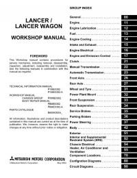
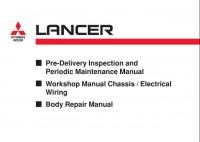
LANCER
WORKSHOP MANUAL
SUPPLEMENT
FOREWORD
This Workshop manual contains procedures for service mechanics, including removal, disassembly, inspection, adjustment, reassembly and installation. Use the following manuals in combination with this manual as required.
TECHNICAL INFORMATION MANUAL PYME0302 PYME0302-A PYME0302-B
WORKSHOP MANUAL
CHASSIS GROUP PWME0302 PWME0302-A PWME0302-B
BODY REPAIR MANUAL PBME0302 PBME0302-A PBME0302-B
PARTS CATALOGUE
B606K006A_
GROUP INDEX
General . . . . . . . . . . . . . . . . . . . . . . . . 00
Fuel . . . . . . . . . . . . . . . . . . . . . . . . . . . 13
All information, illustrations and product descriptions contained in this manual are current as at the time of publication. We, however, reserve the right to make changes at any time without prior notice or obligation.
|
©Mitsubishi Motors Corporation |
Oct. 2005 |

00-1
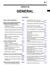
GROUP 00
GENERAL
CONTENTS
|
VEHICLE IDENTIFICATION . . . . . . . |
00-2 GENERAL DATA AND |
|
|
SPECIFICATIONS . . . . . . . . . . . . . . . |
00-3 |
|
00-2 |
GENERAL |
|
VEHICLE IDENTIFICATION |
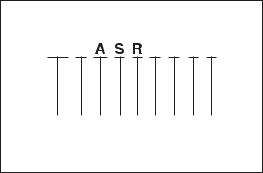
VEHICLE IDENTIFICATION
|
MODELS |
M1001000401448 |
||||
|
Model code |
Engine model |
Price class |
Transmission model |
Fuel supply |
|
|
system |
|||||
|
CS9A |
SRHML6 |
4G63-DOHC (1,997 mL) |
Intense |
F4A4B |
MPI |
|
<2WD, 4A/T> |
|||||
MODEL CODE
CS 9 W L N H M L 6
1 2 3 4 5 6 7 8 9
AC303950AC
|
No. |
Item |
Content |
|
1 |
Development |
CS: MITSUBISHI LANCER |
|
2 |
Engine type |
9: 1,997mL |
|
3 |
Sort |
A: Passenger car |
|
4 |
Body style |
S: 4-door sedan |
|
5 |
Transmission |
R: 4-speed automatic |
|
type |
transmission |
|
|
6 |
Trim level |
H: Intense |
|
7 |
Specification |
M: MPI-DOHC |
|
engine feature |
||
|
8 |
Steering wheel |
L: Left hand |
|
location |
||
|
9 |
Destination |
6: For Europe |
|
GENERAL |
00-3 |
|
GENERAL DATA AND SPECIFICATIONS |
GENERAL DATA AND SPECIFICATIONS
M1001000901197
AC303990AB
|
Items |
CS9A |
||||
|
SRHML6 |
|||||
|
Vehicle dimensions mm |
Front track |
1 |
1,470 |
||
|
Overall width |
2 |
1,715 |
|||
|
Front overhang |
3 |
965 |
|||
|
Wheel base |
4 |
2,600 |
|||
|
Rear overhang |
5 |
970 |
|||
|
Overall length |
6 |
4,535 |
|||
|
Ground clearance (unladen) |
7 |
135 |
|||
|
Overall height (unladen) |
8 |
1,415 |
|||
|
Rear track |
9 |
1,470 |
|||
|
Vehicle weight kg |
Kerb weight |
1,295 |
|||
|
Max. gross vehicle weight |
1,770 |
||||
|
Max. axle weight rating-front |
930 |
||||
|
Max. axle weight rating-rear |
840 |
||||
|
Max. trailer weight |
With brake |
1,000 |
|||
|
Without brake |
400 |
||||
|
Max. trailer-nose weight |
60 |
||||
|
Seating capacity |
5 |
||||
|
Engine |
Model code |
4G63 |
|||
|
Total displacement mL |
1,997 |
||||
|
Maximum output kW/r/min |
99/5,750 |
||||
|
Maximum torque N m/r/min |
176/4,500 |
||||
|
Transmission |
Model code |
F4A4B |
|||
|
Type |
4-speed automatic |
||||
|
Fuel system |
Fuel supply system |
MPI |
|||
|
Maximum speed km/h |
187 |
||||
|
Minimum turning radius m |
5.7 |
||||

NOTES

13D-1
MULTIPOINT FUEL INJECTION (MPI)
<4G63>
CONTENTS
GENERAL . . . . . . . . . . . . . . . . . . . . . . . . . . . . . . . . . 2
Outline of Change . . . . . . . . . . . . . . . . . . . . . . . . . . . . 2
GENERAL INFORMATION . . . . . . . . . . . . . . . . . . . 3 SERVICE SPECIFICATIONS . . . . . . . . . . . . . . . . . 6 SEALANT . . . . . . . . . . . . . . . . . . . . . . . . . . . . . . . . . . 6 SPECIAL TOOLS . . . . . . . . . . . . . . . . . . . . . . . . . . . 7 TROUBLESHOOTING . . . . . . . . . . . . . . . . . . . . . . 10 ON-VEHICLE SERVICE . . . . . . . . . . . . . . . . . . . . 90
Throttle Body (Throttle Valve Area)
Cleaning . . . . . . . . . . . . . . . . . . . . . . . . . . . . . . . . . . . 90
Throttle Position Sensor Adjustment . . . . . . . . . . . . 90
Basic Idle Speed Adjustment . . . . . . . . . . . . . . . . . . 91
Fuel Pressure Test . . . . . . . . . . . . . . . . . . . . . . . . . . . 92
Component Location . . . . . . . . . . . . . . . . . . . . . . . . . 95
Engine Control Relay Continuity Check . . . . . . . . . 96
Fuel Pump Relay Continuity Check . . . . . . . . . . . . . 96
Intake Air Temperature Sensor Check . . . . . . . . . . 97
Engine Coolant Temperature Sensor Check . . . . . 98
Throttle Position Sensor Check . . . . . . . . . . . . . . . . 98
Oxygen Sensor Check . . . . . . . . . . . . . . . . . . . . . . . 99
Injector Check . . . . . . . . . . . . . . . . . . . . . . . . . . . . . . 101
Idle Speed Control (ISC) Servo (Stepper Motor)
Check . . . . . . . . . . . . . . . . . . . . . . . . . . . . . . . . . . . . . 102
Purge Control Solenoid Valve Check . . . . . . . . . . 104 EGR Control Solenoid Valve Check . . . . . . . . . . . 104

|
13D-2 |
MPI <4G63> ï General |
GENERAL
OUTLINE OF CHANGE
Following service procedures have been established due to the addition of vehicles with 4G63-MPI engine for Russia.

|
MPI <4G63> ï General Information |
13D-3 |
GENERAL INFORMATION
The Multipoint Fuel Injection System consists of sensors which detect the engine conditions, the engine-A/T-ECU which controls the system based on signals from these sensors, and actuators which operate under the control of the engine-A/T-ECU. The engine-A/T-ECU
FUEL INJECTION CONTROL
The injector drive times and injection timing are controlled so that the optimum air/fuel mixture is supplied to the engine to correspond to the continually-changing engine operation conditions.
A single injector is mounted at the intake port of each cylinder. Fuel is sent under pressure from the fuel tank by the fuel pump, with the pressure being regulated by the fuel pressure regulator. The fuel thus regulated is distributed to each of the injectors.
Fuel injection is normally carried out once for each cylinder for every two rotations of the crankshaft. The firing order is 1ï3ï4ï2. This is called sequential fuel injection. The
IDLE AIR CONTROL
The idle speed is kept at the optimum speed by controlling the amount of air that bypasses the throttle valve in accordance with changes in idling conditions and engine load during idling. The engine-A/T-ECU drives the idle speed control motor to keep the engine running at the pre-set idle target speed in accordance with the engine coolant temperature and air
IGNITION TIMING CONTROL
The power transistor located in the ignition primary circuit turns ON and OFF to control the primary current flow to the ignition coil. This controls the ignition timing in order to provide the optimum ignition timing with respect to the
SELF-DIAGNOSIS FUNCTION
DWhen an abnormality is detected in one of the sensors or actuators related to
emission control, the engine warning lamp (check engine lamp) illuminates as a warning to the driver.
DWhen an abnormality is detected in one of the sensors or actuators, a diagnosis
carries out activities such as fuel injection control, idle speed control and ignition timing control. In addition, the engine-A/T-ECU is equipped with several diagnosis modes which simplify troubleshooting when a problem develops.
engine-A/T-ECU provides a richer air/fuel mixture by carrying out “open-loop” control when the engine is cold or operating under high load conditions in order to maintain engine performance. In addition, when the engine is warm or operating under normal conditions, the engine-A/T-ECU controls the air/fuel mixture by using the oxygen sensor signal to carry out “closed-loop” control in order to obtain the theoretical air/fuel mixture ratio that provides the maximum cleaning performance from the three way catalyst.
conditioner load. In addition, when the air conditioner switch is turned off and on while the engine is idling, the idle speed control motor operates to adjust the throttle valve bypass air amount in accordance with the engine load conditions in order to avoid fluctuations in the engine speed.
engine operating conditions. The ignition timing is determined by the engine-A/T-ECU from the engine speed, intake air volume, engine coolant temperature and atmospheric pressure.
code corresponding to the abnormality is output.
DThe RAM data inside the engine-A/T-ECU that is related to the sensors and actuators can be read by means of the M.U.T.-II/III. In addition, the actuators can be force-driven under certain circumstances.

13D-4 MPI <4G63> ï General Information
OTHER CONTROL FUNCTIONS
1.Fuel Pump Control
Turns the fuel pump relay ON so that current is supplied to the fuel pump while the engine is cranking or running.
2.A/C Relay Control
Turns the compressor clutch of the A/C ON and OFF.
3.Fan Motor Control
The revolutions of the radiator fan and condenser fan are controlled in response to the engine coolant temperature and vehicle speed.
4.Purge Control Solenoid Valve Control
5.EGR Control Solenoid Valve Control
GENERAL SPECIFICATIONS
|
Item |
Specification |
|
|
Throttle body |
Throttle bore mm |
60 |
|
Throttle position sensor |
Variable resistor type |
|
|
Idle speed control servo |
Stepper motor type |
|
|
Engine-A/T- |
Identification No. |
E6T37983 |
|
ECU |
||
|
Sensors |
Air flow sensor |
Karman vortex type |
|
Barometric pressure sensor |
Semiconductor type |
|
|
Intake air temperature sensor |
Thermistor type |
|
|
Engine coolant temperature sensor |
Thermistor type |
|
|
Oxygen sensor |
Zirconia type |
|
|
Inhibitor switch |
Contact switch type |
|
|
Camshaft position sensor |
Hall element type |
|
|
Crank angle sensor |
Hall element type |
|
|
Detonation sensor |
Piezoelectric type |
|
|
Power steering fluid pressure switch |
Contact switch type |
|
|
Actuators |
Engine control relay |
Contact switch type |
|
Fuel pump relay |
Contact switch type |
|
|
Injector type and number |
Electromagnetic type, 4 |
|
|
Injector identification mark |
HDA250E |
|
|
EGR control solenoid valve |
Duty cycle type solenoid valve |
|
|
Purge control solenoid valve |
Duty cycle type solenoid valve |
|
|
Fuel pressure |
Regulator pressure kPa |
328 |
|
regulator |
||
|
MPI <4G63> ï General Information |
13D-5 |
||||||||
|
MULTI-POINT FUEL INJECTION SYSTEM DIAGRAM |
|||||||||
|
L1 |
Oxygen sensor (front) |
l1 Injector |
|||||||
|
L2 |
Oxygen sensor (rear) |
l2 Idle speed control servo |
|||||||
|
L3 |
Air flow sensor |
Engine-A/T-ECU |
(Stepper motor) |
||||||
|
L4 Intake air temperature sensor |
l3 EGR control solenoid valve |
||||||||
|
L5 |
Throttle position sensor |
l4 Purge control solenoid valve |
|||||||
|
L6 Camshaft position sensor |
|||||||||
|
L7 Crank angle sensor |
|||||||||
|
L8 Barometric pressure sensor |
D |
Engine control relay |
|||||||
|
L9 Engine coolant temperature sensor |
|||||||||
|
L10 Detonation sensor |
D |
Fuel pump relay |
|||||||
|
D |
A/C compressor relay |
||||||||
|
D |
Power supply |
D |
Ignition |
coil |
|||||
|
D |
Fan controller |
||||||||
|
D |
Ignition switch-IG |
D Air flow sensor filter reset signal |
|||||||
|
D |
Ignition switch-ST |
D |
Engine warning lamp |
||||||
|
D |
A/C switch |
D |
Diagnosis output |
||||||
|
D |
A/C load signal |
D |
Alternator G terminal |
||||||
|
D Power steering fluid pressure switch |
D |
Oxygen sensor (front) heater |
|||||||
|
D |
Alternator FR terminal |
D |
Oxygen sensor (rear) heater |
||||||
|
D |
Vehicle speed sensor |
D |
Tachometer |
||||||
|
L4 Intake air temperature sensor |
|||
|
l2 Idle speed control servo |
L3 Air flow sensor |
||
|
(Stepper motor) |
L8 Barometric |
||
|
L5 Throttle position |
|||
|
L6 Camshaft position sensor |
pressure sensor |
||
|
sensor |
|||
|
Fuel pressure |
Air |
||
|
regulator |
M M |
A |
|
To
fuel tank
L1 Oxygen sensor (front)
Catalytic converter
From fuel pump
EGR valve
|
Canister |
|||
|
l1 Injector |
|||
|
L9 Engine coolant |
l3 EGR control |
||
|
temperature sensor |
solenoid valve |
||
|
L10 Detonation sensor |
l4 Purge control |
||
|
L7 |
Crank angle sensor |
solenoid valve |
|
|
L2 |
Oxygen sensor (rear) |
Catalytic converter
![]()
|
13D-6 |
MPI <4G63> ï Service Specifications/Sealant |
|||
|
SERVICE SPECIFICATIONS |
||||
|
Items |
Specifications |
|||
|
Basic idle speed |
r/min |
750 r 50 |
||
|
Throttle position sensor adjusting voltage |
mV |
535 ï 735 |
||
|
Throttle position sensor resistance k: |
3.5 ï 6.5 |
|||
|
Idle speed control servo coil resistance (at 20_C) : |
28 ï 33 |
|||
|
Intake air temperature sensor |
ï20_C |
13 ï 17 |
||
|
resistance k: |
||||
|
0_C |
5.3 ï 6.7 |
|||
|
20_C |
2.3 ï 3.0 |
|||
|
40_C |
1.0 ï 1.5 |
|||
|
60_C |
0.56 ï0.76 |
|||
|
80_C |
0.30 ï 0.42 |
|||
|
Engine coolant temperature |
ï20_C |
14 ï 17 |
||
|
sensor resistance |
k: |
|||
|
0_C |
5.1 ï 6.5 |
|||
|
20_C |
2.1 ï 2.7 |
|||
|
40_C |
0.9 ï 1.3 |
|||
|
60_C |
0.48 ï 0.68 |
|||
|
80_C |
0.26 ï 0.36 |
|||
|
Oxygen sensor output voltage (at racing) |
V |
0.6 ï 1.0 |
||
|
Oxygen sensor heater |
front |
4.5 ï 8.0 |
||
|
resistance (at 20_C) : |
||||
|
rear |
11 ï 18 |
|||
|
Fuel pressure kPa |
Vacuum hose disconnection |
324 ï 343 at kerb idle |
||
|
Vacuum hose connection |
Approximately 265 at kerb idle |
|||
|
Injector coil resistance (at 20_C) : |
10.5 ï 13.5 |
|||
SEALANT
|
Item |
Specified sealant |
Remark |
|
Engine coolant temperature sensor |
3M Nut Locking Part No. 4171 or equivalent |
Drying sealant |
|
threaded portion |
||

|
MPI <4G63> ï Special Tools |
13D-7 |
|||||
|
SPECIAL TOOLS |
||||||
|
Tool |
Number |
Name |
Use |
|||
|
MB991502 |
M.U.T.-II sub |
D |
Reading diagnosis code |
|||
|
assembly |
D |
MPI system inspection |
||||
|
D Measurement of fuel pressure |
||||||
|
MB991955 |
M.U.T.-III sub |
D |
Reading diagnosis code |
|
A: MB991824 |
assembly |
D |
MPI system inspection |
|
B: MB991827 |
D Measurement of fuel pressure |
||
|
C: MB991910 |
|||
|
D: MB991911 |
|||
|
E: MB991825 |
|||
|
F: MB991826 |
|||
|
M.U.T.-III sub |
|||
|
assembly |
A:Vehicle communication interface (V.C.I.)
B:M.U.T.-III USB cable
C:M.U.T.-III main harness A (Vehicles with CAN communication system)
D:M.U.T.-III main harness B (Vehicles without CAN communication system)
E:M.U.T.-III measurement adapter
F:M.U.T.-III trigger harness
|
MB991348 |
Test harness set |
D Inspection using an oscilloscope |
|

|
13D-8 |
MPI <4G63> ï Special Tools |
||||
|
Tool |
Number |
Name |
Use |
||
|
MB991709 |
Test harness |
D |
Measurement of voltage during |
||
|
troubleshooting |
|||||
|
D |
Inspection using an oscilloscope |
||||
|
D |
Check of idle speed control servo |
||||
|
MD998478 |
Test harness |
D |
Measurement of voltage during |
||
|
(3-pin, triangle) |
Troubleshooting |
||||
|
D |
Inspection using an oscilloscope |
||||
|
MB991536 |
Check harness for |
D |
Measurement of voltage during |
||
|
throttle |
position |
Troubleshooting |
|||
|
sensor adjustment |
D |
Adjusting of throttle position sensor |
|||
|
MD998464 |
Test harness |
D |
Measurement of voltage during |
||
|
(4-pin, square) |
Troubleshooting |
||||
|
D |
Inspection of oxygen sensor (front) |
||||
|
MB991658 |
Test harness |
D |
Measurement of voltage during |
||
|
Troubleshooting |
|||||
|
D |
Inspection of oxygen sensor (rear) |
||||
|
MB991223 |
Harness set |
D |
Check at the ECU terminals |
||
|
A: MB991219 |
A: Test harness |
A: |
Connector pin contact pressure inspection |
||
|
B: MB991220 |
B: LED harness |
B: |
Power circuit inspection |
||
|
C: |
Power circuit inspection |
||||
|
C: MB991221 |
C: LED harness |
||||
|
D: |
Commercial tester connection |
||||
|
D: MB991222 |
adapter |
||||
|
D: Probe |
|||||
|
MPI <4G63> ï Special Tools |
13D-9 |
|||
|
Tool |
Number |
Name |
Use |
|
|
MD998709 |
Adaptor hose |
Measurement of fuel pressure |
||
|
MD998742 |
Hose adaptor |
|||
|
MB991637 |
Fuel pressure |
|||
|
gauge set |
||||
|
MB991981 |
Fuel pressure |
|||
|
gauge set |
||||
|
MB992076 |
Injector test set |
Checking the spray condition of injectors |
||
|
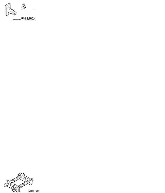
MB991607 |
Injector test |
|||
|
harness |
||||
|
MD998741 |
Injector test |
|||
|
adaptor |
||||
|
MB991976 |
Injector test holder |
|||
|
assembly |
||||

|
13D-10 |
MPI <4G63> ï Troubleshooting |
Engine warning lamp (check engine lamp)
TROUBLESHOOTING
DIAGNOSIS TROUBLESHOOTING FLOW
Refer to GROUP 00 ï How to Use Troubleshooting/Inspection Service Point.
NOTE
If the engine-A/T-ECU is replaced, ring antenna with built in immobilizer-ECU should be replaced, ignition key can be kept, but must be registered.
DIAGNOSIS FUNCTION
ENGINE WARNING LAMP (CHECK ENGINE LAMP)
If an abnormality occurs in any of the following items related to the MPI system, the engine warning lamp will illuminate or flash. If the lamp remains illuminated or if the lamp illuminates while the engine is running, check the diagnosis code output.
However, the warning lamp will illuminate as bulb check for five seconds whenever the ignition switch is turned to the ON position.
Engine warning lamp inspection items
Engine-A/T-ECU
Oxygen sensor (front)
Air flow sensor
Intake air temperature sensor
Throttle position sensor
Engine coolant temperature sensor
Crank angle sensor
Camshaft position sensor
Barometric pressure sensor
Detonation sensor
Ignition coil, power transistor unit
Injector
Immobilizer system
Oxygen sensor (rear)
NOTE
If the engine warning lamp illuminates because of a malfunction of the engine-A/T-ECU, communication between M.U.T.-II/III and the engine-A/T-ECU is impossible. In this case, the diagnosis code cannot be read.

|
MPI <4G63> ï Troubleshooting |
13D-11 |
METHOD OF READING AND ERASING DIAGNOSIS
CODES
Refer to GROUP 00 ï How to Use Troubleshooting/Inspection
Service Points.
INSPECTION USING M.U.T.-II/III DATA LIST AND
ACTUATOR TESTING
1.Carry out inspection by means of the data list and the actuator test function. If there is an abnormality, check and repair the chassis harnesses and components.
2.After repairing, re-check using the M.U.T.-II/III and check that the abnormal input and output have returned to normal as a result of the repairs.
3.Erase the diagnosis code memory.
4.Remove the M.U.T.-II/III, and then start the engine again and carry out a road test to confirm that the problem has disappeared.
FAIL-SAFE FUNCTION REFERENCE TABLE
When the main sensor malfunctions are detected by the diagnosis function, the vehicle is controlled by means of the pre-set control logic to maintain safe conditions for driving.
|
Malfunctioning item |
Control contents during malfunction |
|
Air flow sensor |
1. Uses the throttle position sensor signal and engine speed signal (crank angle sensor |
|
signal) to take reading of the basic injector drive time and basic ignition timing from |
|
|
the pre-set mapping. |
|
|
2. Fixes the ISC servo in the appointed position so idle control is not performed. |
|
|
Intake air temperature |
Controls as if the intake air temperature is 25_C. |
|
sensor |
|
|
Throttle position |
No increase in fuel injection amount during acceleration due to the throttle position sensor |
|
sensor (TPS) |
signal. |
|
Engine coolant |
Controls as if the engine coolant temperature is 80_C. |
|
temperature sensor |
|
|
Camshaft position |
Injects fuel into the cylinders in the order 1-3-4-2 with irregular timing. |
|
sensor |
(However, after the ignition switch is turned to ON, the No. 1 cylinder top dead centre is not |
|
detected at all.) |
|
|
Barometric pressure |
Controls as if the barometric pressure is 101 kPa. |
|
sensor |
|
|
Detonation sensor |
Switches the ignition timing from ignition timing for super petrol to ignition timing for standard |
|
petrol. |
|
|
Ignition coil, power |
Cuts off the fuel supply to cylinders with an abnormal ignition. |
|
transistor |
|
|
Alternator FR terminal |
Does not control the output of the alternator according to an electrical load. (works as a |
|
normal alternator) |
|

|
13D-12 |
MPI <4G63> ï Troubleshooting |
|
|
INSPECTION CHART FOR DIAGNOSIS CODES |
||
|
Code No. |
Diagnosis item |
Reference page |
|
11 |
Oxygen sensor (front) system |
13D-13 |
|
12 |
Air flow sensor system |
13D-15 |
|
13 |
Intake air temperature sensor system |
13D-16 |
|
14 |
Throttle position sensor system |
13D-18 |
|
21 |
Engine coolant temperature sensor system |
13D-20 |
|
22 |
Crank angle sensor system |
13D-22 |
|
23 |
Camshaft position sensor system |
13D-23 |
|
24 |
Vehicle speed signal system |
13D-25 |
|
25 |
Barometric pressure sensor system |
13D-26 |
|
31 |
Detonation sensor system |
13D-28 |
|
41 |
Injector system |
13D-29 |
|
44 |
Ignition coil (power transistor) system |
13D-30 |
|
54 |
Immobilizer system |
13D-31 |
|
59 |
Oxygen sensor (rear) system |
13D-32 |
|
64 |
Alternator FR terminal system |
13D-34 |
NOTE
1.Do not replace the engine-A/T-ECU until a through terminal check reveals there are no short/open circuit.
2.Check that the engine-A/T-ECU earth circuit is normal before checking for the cause of the problem.
|
MPI <4G63> ï Troubleshooting |
13D-13 |
||
|
INSPECTION PROCEDURE FOR DIAGNOSIS CODE |
|||
|
Code No. 11 Oxygen sensor (front) system |
Probable cause |
||
|
Range of Check |
D Malfunction of the oxygen sensor (front) |
||
|
D More than 3 minutes passed after completion of start of engine |
D Oxygen sensor (front) circuit disconnection, |
||
|
D The engine coolant temperature is approximately more than 80_C. |
short-circuit, or connector contact defect. |
||
|
D Intake air temperature 0 ï 55_C. |
D Malfunction of the engine-A/T-ECU |
||
|
D The engine speed is more than 1,800 ï 3,500 r/min. |
|||
|
D The volumetric efficiency is 16 ï 60% or more. |
|||
|
Set Conditions |
|||
|
D For 30 seconds, the oxygen sensor output voltage continues to be 0.5 V or |
|||
|
lower, or 0.5 V or higher. |
|||
|
D The Engine-A/T-ECU monitors for this condition once during the drive cycle. |
|||
M.U.T.-II/III Data list
DNo. 11 Oxygen sensor (front) (Refer to P.13D-66.)
NG
Check the following connector:
B-17
OK
Measure at the B-17 oxygen sensor (front) connector.
DDisconnect connector to measure at the harness side
DResistance between terminal No. 2 and earth.
OK: Less than 2 :
OK
Measure at the B-17 oxygen sensor (front) connector.
DUsing the test harness (MD998464), connect the
connector, and measure at the pickup harness.
D Engine: After warm-up
(1)Voltage between terminal No. 2 and earth
OK: Less than 0.5 V
(2)Voltage between terminal No. 4
and the earth
D At rapid deceleration from 4,000 r/min
OK: 200 mV or less
DDuring rapid racing OK: 600 ï 1,000 mV
OK
To the next page
|
OK |
||||||||
|
Intermittent malfunction |
||||||||
|
(Refer to GROUP 00 ï Points to Note |
||||||||
|
for Intermittent Malfunctions.) |
||||||||
|
NG |
||||||||
|
Repair |
NG |
|||||||
|
NG |
Repair |
|||||||
|
Check the following connector: |
||||||||
|
C-124 |
||||||||
|
OK |
||||||||
|
NG |
||||||||
|
Check the harness between the |
Repair |
|||||||
|
oxygen sensor (front) and |
||||||||
|
engine-A/T-ECU. |
||||||||
|
OK |
||||||||
|
NG |
||||||||
|
M.U.T.-II/III Data list |
Replace the engine-A/T-ECU. |
|||||||
|
D No. 11 Oxygen sensor (front) |
||||||||
|
(Refer to P.13D-66.) |
||||||||
|
OK |
||||||||
|
Intermittent malfunction |
||||||||
|
(Refer to GROUP 00 ï Points to Note |
||||||||
|
(1) NG |
for Intermittent Malfunctions.) |
NG |
Repair |
|||||
|
Check the following connector: |
||||||||
|
C-124 |
||||||||
|
OK |
||||||||
|
NG |
||||||||
|
Check the harness between the |
Repair |
|||||||
|
oxygen sensor (front) and |
||||||||
|
engine-A/T-ECU. |
||||||||
|
(2) NG |
NG |
|||||||
|
Check the oxygen sensor (front). |
Replace the oxygen sensor (front). |
|||||||
|
(Refer to P.13D-99.) |
||||||||
|
OK |
||||||||
|
NG |
Repair |
|||||||
|
Check the following connector: |
||||||||
|
C-126 |
||||||||
|
OK |
||||||||
|
NG |
Repair |
|||||||
|
Check the harness between the |
||||||||
|
oxygen sensor (front) and |
||||||||
|
engine-A/T-ECU. |
||||||||

|
13D-14 |
MPI <4G63> ï Troubleshooting |
|
From the previous page |
||||||||
|
OK |
||||||||
|
NG |
NG |
|||||||
|
Measure at the C-126 engine-A/T-ECU |
Check the following connector: |
Repair |
||||||
|
connector. |
C-126 |
|||||||
|
D Measure the engine-A/T-ECU |
||||||||
|
OK |
||||||||
|
terminal voltage. |
||||||||
|
D |
Engine: After warm-up |
Check and repair the harness between |
||||||
|
D |
Voltage between terminal No. 71 |
|||||||
|
the oxygen sensor (front) and |
||||||||
|
and earth. |
||||||||
|
engine-A/T-ECU. |
||||||||
|
D |
At rapid deceleration from 4,000 |
|||||||
|
r/min |
||||||||
|
OK: 200 mV or less |
DDuring rapid racing OK: 600 ï 1,000 mV
|
OK |
||||
|
NG |
||||
|
Check the following connectors: |
Repair |
|||
|
C-124, C-126 |
||||
|
OK |
||||
|
NG |
||||
|
M.U.T.-II/III Data list |
Replace the engine-A/T-ECU. |
|||
|
D No. 11 Oxygen sensor (front) |
||||
|
(Refer to P.13D-66.) |
||||
|
OK |
||||
|
Intermittent malfunction |
||||
|
(Refer to GROUP 00 ï Points to Note |
||||
|
for Intermittent Malfunctions.) |
||||

|
MPI <4G63> ï Troubleshooting |
13D-15 |
|
|
Code No. 12 Air flow sensor system |
Probable cause |
|
|
Range of Check |
D Malfunction of the air flow sensor |
|
|
D The engine speed is more than 500 r/min |
D Air flow sensor circuit disconnection, short-circuit, |
|
|
Set Condition |
or connector contact defect |
|
|
D The sensor output frequency is less than 3.3 Hz for 4 seconds. |
D Malfunction of the engine-A/T-ECU |
|
M.U.T.-II/III Data list
DNo. 12 Air flow sensor (Refer to P.13D-66.)
NG
Check the following connector:
B-08
OK
Measure at the B-08 air flow sensor connector.
DDisconnect the connector to measure at the harness side
(1)Voltage between terminal No. 3 and earth
(Ignition switch: ON) OK: 4.9 ï 5.1 V
(2)Voltage between terminal No. 4 and earth
(Ignition switch: ON) OK: System voltage
(3)Resistance between terminal No. 5 and earth
OK: Less than 2 :
OK
To the next page
OK
 Intermittent malfunction
(Refer to GROUP 00 ï Points to Note for Intermittent Malfunctions.)
NG
 Repair
|
(1) NG |
OK |
|||||
|
Measure at the C-124 engine-A/T-ECU |
||||||
|
connector. |
||||||
|
D Measure the voltage of the |
||||||
|
engine-A/T-ECU terminal. |
||||||
|
D |
Ignition switch: ON |
|||||
|
D Voltage between terminal No. 65 |
||||||
|
and earth. |
||||||
|
OK: 4.9 ï 5.1 V |
||||||
|
NG |
||||||
Check the following connector: NG C-124
OK
 NG Check the harness between the air
flow sensor and engine-A/T-ECU.
OK
NG
M.U.T.-II/III Data list
DNo. 12 Air flow sensor (Refer to P.13D-66.)
|
OK |
||||||
|
Intermittent malfunction |
||||||
|
(Refer to GROUP 00 ï Points to Note |
||||||
|
for Intermittent Malfunctions.) |
||||||
|
(2) NG |
NG |
|||||
|
Check the following connector: |
||||||
|
B-16X |
||||||
|
OK |
||||||
|
Check the harness between the air |
||||||
|
flow sensor and engine control relay. |
||||||
|
(3) NG |
NG |
|||||
|
Check the following connector: |
||||||
|
C-122 |
||||||
|
OK |
||||||
|
NG |
||||||
|
Check the harness between the air |
||||||
|
flow sensor and engine-A/T-ECU. |
||||||
|
OK |
NG |
|||||
|
M.U.T.-II/III |
Data list |
|||||
DNo. 12 Air flow sensor (Refer to P.13D-66.)
OK
Intermittent malfunction
(Refer to GROUP 00 ï Points to Note for Intermittent Malfunctions.)
 Check the following connector:
C-124
OK NG
Repair
Check and repair the harness between the air flow sensor and engine-A/T- ECU.
 Repair
 Repair

 Replace the engine-A/T-ECU.
 Repair
 Repair
 Repair
 Replace the engine-A/T-ECU.
![]()
|
13D-16 |
MPI <4G63> ï Troubleshooting |
|||||||||||||||
|
From the previous page |
||||||||||||||||
|
OK |
NG |
|||||||||||||||
|
NG |
||||||||||||||||
|
Measure at the B-08 air flow sensor |
Check the following connector: |
Repair |
||||||||||||||
|
connector. |
C-122 |
|||||||||||||||
|
D |
Using the test harness |
OK |
||||||||||||||
|
(MB991709), connect the |
||||||||||||||||
|
NG |
||||||||||||||||
|
connector, and measure at the |
Check the harness between the air |
Repair |
||||||||||||||
|
D |
pickup. |
flow sensor and engine-A/T-ECU. |
||||||||||||||
|
Ignition switch: ON |
||||||||||||||||
|
OK |
||||||||||||||||
|
D Voltage between terminal No. 7 |
||||||||||||||||
|
and earth. |
||||||||||||||||
|
Replace the air flow sensor. |
||||||||||||||||
|
OK: 7 ï 8 V |
||||||||||||||||
|
OK |
||||||||||||||||
|
NG |
NG |
|||||||||||||||
|
Measure at the B-08 air flow sensor |
Check the following connector: |
Repair |
||||||||||||||
|
connector. |
C-122 |
|||||||||||||||
|
D |
Using the test harness |
|||||||||||||||
|
OK |
||||||||||||||||
|
(MB991709), connect the |
||||||||||||||||
|
NG |
||||||||||||||||
|
connector, and measure at the |
Repair |
|||||||||||||||
|
pickup harness. |
Check the harness between air flow |
|||||||||||||||
|
sensor and engine-A/T-ECU. |
||||||||||||||||
|
D Voltage between terminal No. 7 |
||||||||||||||||
|
OK |
||||||||||||||||
|
and earth. |
||||||||||||||||
|
OK: Engine: idle |
NG |
|||||||||||||||
|
0 ï 1 V |
M.U.T.-II/III Data list |
Replace the engine-A/T-ECU. |
||||||||||||||
|
Engine: 3,000 r/min |
D No. 12 Air flow sensor |
|||||||||||||||
|
6 ï 9 V |
(Refer to P.13D-66.) |
|||||||||||||||
|
OK |
OK |
|||||||||||||||
|
Intermittent malfunction |
||||||||||||||||
|
(Refer to GROUP 00 ï Points to Note |
||||||||||||||||
|
for Intermittent Malfunctions.) |
Measure the output waveform at the B-08 air flow sensor connector (using an analyzer).
D Using the test harness (MB991709), connect the connector, and measure at the pickup harness.
D Engine: Idle
DVoltage between terminal No. 3 and earth.
OK: Output the waveform as shown on P.13D-79 (inspection procedure by analyzer), and check that there is noise in the output waveform.
OK
M.U.T.-II/III Data list
DNo. 12 Air flow sensor (Refer to P.13D-66.)
OK
Intermittent malfunction
(Refer to GROUP 00 ï Points to Note for Intermittent Malfunctions.)
NG
 Replace the air flow sensor.
|
OK |
|||
|
Check the trouble symptom. |
End |
||
|
NG |
|||
|
NG |
|||
|
Check the following connectors: |
Repair |
||
|
B-16X, C-122, C-124 |
|||
|
OK |
|||
|
NG |
|||
|
Check the harness between the air |
Repair |
||
|
flow sensor and engine control relay. |
|||
|
OK |
|||
Check the harness between the air flow sensor and engine-A/T-ECU.
NG
 Replace the engine-A/T-ECU.
|
Code No. 13 Intake air temperature sensor system |
Probable cause |
|
|
Range of Check |
D Malfunction of the intake air temperature sensor |
|
|
D 60 seconds after the ignition switch is set to the “ON” position, or after the |
D Intake air temperature sensor circuit disconnection, |
|
|
completion of the start of engine. |
short-circuit, or connector contact defect |
|
|
Set Conditions |
D Malfunction of the engine-A/T-ECU |
|
|
D The sensor output voltage is more than 4.6 V for 4 seconds (Equivalent to intake |
||
|
air temperature less than ï40_C) |
||
|
or |
||
|
D The sensor output voltage is less than 0.2 V for 4 seconds (Equivalent to intake |
||
|
air temperature of more than 120_C) |
||
|
MPI <4G63> ï Troubleshooting |
13D-17 |
|
OK |
||||||||
|
M.U.T.-II/III Data list |
Intermittent malfunction |
|||||||
|
D No. 13 Intake air temperature |
(Refer to GROUP 00 ï Points to Note |
|||||||
|
sensor |
for Intermittent Malfunctions.) |
|||||||
|
OK: Ambient temperature (More |
||||||||
|
or less the same as the air |
||||||||
|
temperature) |
||||||||
|
NG |
||||||||
|
NG |
Repair |
|||||||
|
Check the following connector: |
||||||||
|
B-08 |
||||||||
|
OK |
||||||||
|
NG |
||||||||
|
Check the intake air temperature |
Replace the intake air temperature |
|||||||
|
sensor alone. (Refer to P.13D-97.) |
sensor. |
|||||||
|
OK |
||||||||
|
(1) NG |
NG |
|||||||
|
Measure at the B-08 air flow sensor |
Check the following connector: |
|||||||
|
connector. |
C-122 |
|||||||
|
D Disconnect the connector to |
||||||||
|
OK |
||||||||
|
measure at the harness side |
||||||||
|
NG |
||||||||
|
(1) Resistance between terminal No. |
||||||||
|
Check the harness between the air |
||||||||
|
5 and earth |
||||||||
|
flow sensor and engine-A/T-ECU. |
||||||||
|
OK: Less than 2 : |
||||||||
|
(2) Voltage between terminal No. 6 |
OK |
|||||||
|
and earth |
NG |
|||||||
|
(Ignition switch: ON) |
M.U.T.-II/III Data list |
|||||||
|
OK: 4.5 ï 4.9 V |
D No. 13 Intake air temperature |
|||||||
|
sensor |
||||||||
|
OK: Ambient temperature (More |
||||||||
|
or less the same as the air |
||||||||
|
temperature) |
||||||||
|
OK |
||||||||
|
Intermittent malfunction |
||||||||
|
(Refer to GROUP 00 ï Points to Note |
||||||||
|
for Intermittent Malfunctions.) |
||||||||
|
(2) NG |
OK |
|||||||
|
Measure at the C-124 engine-A/T-ECU |
||||||||
|
connector. |
||||||||
|
D Measure the engine-A/T-ECU |
||||||||
|
terminal voltage. |
||||||||
|
D Disconnect the B-08 air flow |
||||||||
|
sensor connector. |
||||||||
|
D Ignition switch: ON |
||||||||
|
D Voltage between terminal No. 64 |
||||||||
|
and earth. |
||||||||
|
OK: 4.5 ï 4.9 V |
||||||||
|
NG |
||||||||
|
NG |
||||||||
|
Check the following connector: |
||||||||
|
C-124 |
||||||||
|
OK |
NG |
|||||||
|
OK |
||||||||
|
Check the harness between the air |
||||||||
|
To the next page |
flow sensor and engine-A/T-ECU. |
|||||||
|
OK |
||||||||
|
NG |
||||||||
|
M.U.T.-II/III Data list |
||||||||
|
D No. 13 intake air temperature |
||||||||
|
sensor |
||||||||
|
OK: Ambient temperature (More |
||||||||
|
or less the same as air |
||||||||
|
temperature) |
||||||||
|
OK |
||||||||
|
Intermittent malfunction |
||||||||
|
(Refer to GROUP 00 ï Points to Note |
||||||||
|
for Intermittent Malfunctions.) |
 Repair
Repair
 Replace the engine-A/T-ECU.
 Check the following connector:
C-124
OK NG
Repair
Check and repair the harness between the air flow sensor and engine-A/T- ECU.
 Repair
 Repair

 Replace the engine-A/T-ECU.

|
13D-18 |
MPI <4G63> ï Troubleshooting |
||||||||||
|
From the previous page |
|||||||||||
|
OK |
|||||||||||
|
NG |
NG |
||||||||||
|
Measure at the B-08 air flow sensor |
Check the following connectors: |
Repair |
|||||||||
|
connector. |
C-122, C-124 |
||||||||||
|
D Using the test harness |
|||||||||||
|
OK |
|||||||||||
|
(MB991709), connecting only |
|||||||||||
|
connector terminals No. 5 and |
|||||||||||
|
Check and repair the harness between |
|||||||||||
|
No. 6, and measure at the |
|||||||||||
|
the air flow sensor and engine-A/T- |
|||||||||||
|
pickup harness. |
|||||||||||
|
ECU. |
|||||||||||
|
D Ignition switch: ON |
|||||||||||
DVoltage between terminal No. 6
and earth.
OK: Ambient temperature ï20_C
|
3.8 |
ï 4.4 V |
||||
|
Ambient temperature 0_C |
|||||
|
3.2 |
ï 3.8 V |
||||
|
Ambient temperature 20_C |
|||||
|
2.3 |
ï 2.9 V |
||||
|
Ambient temperature 40_C |
|||||
|
1.5 |
ï 2.1 V |
||||
|
Ambient temperature 60_C |
|||||
|
0.8 |
ï 1.4 V |
||||
|
Ambient temperature 80_C |
|||||
|
0.4 |
ï 1.0 V |
||||
|
OK |
|||||
|
NG |
|||||
|
M.U.T.-II/III |
Data list |
Replace the engine-A/T-ECU. |
|||
|
D No. 13 intake air temperature |
|||||
|
sensor |
|||||
|
OK: Ambient temperature (More |
|||||
|
or less the same as the air |
|||||
|
temperature) |
|||||
|
OK |
|||||
|
Intermittent malfunction |
|||||
|
(Refer to GROUP 00 ï Points to Note |
|||||
|
for Intermittent Malfunctions.) |
|||||
|
Code No. 14 Throttle position sensor system |
Probable cause |
|||||||
|
Range of Check |
D Malfunction of the throttle position sensor |
|||||||
|
D 60 seconds after the ignition switch is set to the “ON” position, or after the |
D Improper connector contact, open circuit or |
|||||||
|
completion of start of engine. |
short-circuited harness wire |
|||||||
|
Set Conditions |
D Malfunction of the engine-A/T-ECU |
|||||||
|
D The sensor output voltage is 4.3 V or more for 4 seconds and volumetric |
||||||||
|
efficiency 40 % or less. |
||||||||
|
or |
||||||||
|
D The sensor output voltage is 0.2 V or less for 2 seconds |
||||||||
|
OK |
||||||||
|
M.U.T.-II/III Data list |
Intermittent malfunction |
|||||||
|
14 Throttle position sensor |
(Refer to GROUP 00 ï Points to |
|||||||
|
(Refer to P.13D-66, DATA LIST |
Note for Intermittent Malfunctions.) |
|||||||
|
REFERENCE TABLE.) |
||||||||
|
NG |
||||||||
|
NG |
||||||||
|
Check the throttle position sensor. |
Replace |
|||||||
|
(Refer to P.13D-98.) |
||||||||
|
OK |
||||||||
|
NG |
||||||||
|
Check the following connector: |
Repair |
|||||||
|
B-06 |
||||||||
|
OK |
||||||||
|
To the next page |
||||||||
|
MPI <4G63> ï Troubleshooting |
13D-19 |
From the previous page
OK
Measure at throttle position sensor connector B-06.
DDisconnect the connector and measure at the harness side.
(1)Voltage between terminal 1 and earth
(Ignition switch: ON) OK: 4.9 ï 5.1 V
(2)Resistance between terminal 4 and earth
OK: 2 : or less
OK
Measure at throttle position sensor connector B-06.
DUse test harness (MB991536) to connect the connector, and
measure at the pick-up harness. D Ignition switch: ON
(1)Voltage between terminal 1 and
earth
OK: 4.9 ï 5.1 V
(2)Voltage between terminal 4 and earth
OK: 0.5 V or less
(3)Voltage between terminal 2 and earth
OK: Accelerator pedal fully released: 0.335 ï 0.935 V
Accelerator pedal fully depressed: 4.4 ï 5.3 V
OK
To the next page
|
(1) NG |
OK |
|||||||||||||
|
Measure at engine-A/T-ECU |
Check the following connector: |
|||||||||||||
|
connector C-124. |
C-124 |
|||||||||||||
|
D |
Measure the voltage at the |
|||||||||||||
|
OK |
NG |
|||||||||||||
|
engine-A/T-ECU terminals. |
||||||||||||||
|
Repair |
||||||||||||||
|
D |
Ignition switch: ON |
|||||||||||||
|
D |
Voltage between terminal 46 and |
|||||||||||||
|
Check the harness wire between the |
||||||||||||||
|
earth |
||||||||||||||
|
throttle position sensor and the |
||||||||||||||
|
OK: 4.9 ï 5.1 V |
||||||||||||||
|
engine-A/T-ECU, and repair if |
||||||||||||||
|
NG |
necessary. |
|||||||||||||
|
NG |
||||||||||||||
|
Check the following connector: |
Repair |
|||||||||||||
|
C-124 |
||||||||||||||
|
OK |
||||||||||||||
|
NG |
||||||||||||||
|
Check the harness wire between the |
Repair |
|||||||||||||
|
throttle position sensor and the |
||||||||||||||
|
engine-A/T-ECU. |
||||||||||||||
|
OK |
NG |
|||||||||||||
|
(2) NG |
Check the trouble symptoms. |
Replace the engine-A/T-ECU. |
||||||||||||
|
NG |
||||||||||||||
|
Check the following connector: |
Repair |
|||||||||||||
|
C-124 |
||||||||||||||
|
OK |
|||||
|
Check the harness wire between the |
|||||
|
throttle position sensor and the |
|||||
|
engine-A/T-ECU. |
|||||
|
OK |
|||||
|
Check the trouble symptoms. |
|||||
|
(1) NG |
Check the following connector: |
||||
|
(2) NG |
|||||
|
C-124 |
|||||
|
OK |
|||||
NG Repair
NG
 Replace the engine-A/T-ECU.
NG
 Repair
Check the harness wire between the throttle position sensor and the engine-A/T-ECU.
(3) NG
 Adjust the throttle position sensor. (Refer to P.13D-98.)
|
NG |
||||
|
Check the following connector: |
||||
|
Repair |
||||
|
C-126 |
||||
|
OK |
||||
|
Check the harness wire between the |
||||
|
throttle position sensor and the |
||||
|
engine-A/T-ECU, and repair if |
||||
|
necessary. |
||||
|
13D-20 |
MPI <4G63> ï Troubleshooting |
From the previous page
|
OK |
||||
|
NG |
||||
|
Measure at the engine-A/T-ECU |
||||
|
connector C-126 |
DMeasure voltage at the engine-A/T-ECU terminal.
D Ignition switch: ON
DVoltage between terminal 78 and earth
OK: Accelerator pedal fully re-
leased: 0.335 ï 0.935 V Accelerator pedal fully de- OK pressed: 4.4 ï 5.3 V
|
NG |
||||
|
Check the following connector: |
||||
|
Repair |
||||
|
C-126 |
||||
|
OK |
||||
Check the harness wire between the throttle position sensor and the engine-A/T-ECU, and repair if necessary.
NG
Check the following connectors:  Repair
C-124, C-126
OK
Check the trouble symptoms.
NG
Replace the engine-A/T-ECU.
|
Code No. 21 Engine coolant temperature sensor system |
Probable cause |
|
Range of Check |
D Malfunction of the engine coolant temperature |
|
D 60 seconds after the ignition switch is set to the “ON” position, or after the |
sensor |
|
completion of start of engine. |
D Open or short circuit in the engine coolant |
|
Set Conditions |
temperature sensor circuit or loose connector |
|
D The sensor output voltage is 4.6 V or more for 4 seconds (equivalent to |
contact |
|
ï45_C or lower of engine coolant temperature) |
D Malfunction of the engine-A/T-ECU |
|
or |
|
|
D The sensor output voltage is 0.1 V or less for 4 seconds (equivalent to |
|
|
140_C or higher of engine coolant temperature) |
|
|
Range of Check |
|
|
D Engine: After starting |
|
|
Set Condition |
|
|
D The engine coolant temperature has reduced from over 40_C to less than |
|
|
40_C, and that condition has lasted for five minutes or more. |
|
M.U.T.-II/III Data list
21 Engine coolant temperature sensor
OK: When the engine is cold, the temperature is roughly the same as ambient temperature. If warm, it is 80 ï 120_C.
NG
Measure at engine coolant temperature sensor connector B-111.
D Disconnect the connector and measure at the sensor side.
DResistance between terminals 1 and 2
OK: At 20_C of engine coolant temperature: 2.1 ï 2.7 k: At 80_C of engine coolant temperature:
0.26ï 0.36 k:
 OK
OK
Check the following connector:
B-111
OK
To the next page
OK
Intermittent malfunction
(Refer to GROUP 00 ï Points to Note for Intermittent Malfunctions.)
NG
 Replace
NG
 Repair

|
MPI <4G63> ï Troubleshooting |
13D-21 |
|||||||||||||||||||||||||
|
From the previous page |
||||||||||||||||||||||||||
|
OK |
OK |
|||||||||||||||||||||||||
|
(1) NG |
||||||||||||||||||||||||||
|
Measure at engine coolant |
Measure at engine-A/T-ECU |
Check the following connector: |
||||||||||||||||||||||||
|
C-124 |
||||||||||||||||||||||||||
|
temperature sensor connector B-111. |
connector C-124. |
|||||||||||||||||||||||||
|
D |
Disconnect the connector and |
D |
Measure the voltage at the |
OK |
NG |
|||||||||||||||||||||
|
measure at the harness side. |
D |
engine-A/T-ECU terminal. |
Repair |
|||||||||||||||||||||||
|
(1) Voltage between terminal 1 and |
Disconnect connector B-111. |
|||||||||||||||||||||||||
|
earth |
D |
Ignition switch: ON |
Check the harness wire between the |
|||||||||||||||||||||||
|
(Ignition switch: ON) |
D |
Voltage between terminal 44 and |
engine coolant temperature sensor |
|||||||||||||||||||||||
|
OK: 4.5 ï 4.9 V |
earth |
and the engine-A/T-ECU, and repair |
||||||||||||||||||||||||
|
(2) Resistance between terminal 2 |
OK: 4.5 ï 4.9 V |
if necessary. |
||||||||||||||||||||||||
|
and earth |
NG |
|||||||||||||||||||||||||
|
OK: 2 : or less |
||||||||||||||||||||||||||
|
NG |
||||||||||||||||||||||||||
|
Check the following connector: |
Repair |
|||||||||||||||||||||||||
|
C-124 |
||||||||||||||||||||||||||
|
OK |
||||||||||||||||||||||||||
|
Check the harness wire between the |
NG |
Repair |
||||||||||||||||||||||||
|
engine coolant temperature sensor |
||||||||||||||||||||||||||
|
and the engine-A/T-ECU. |
||||||||||||||||||||||||||
|
OK |
||||||||||||||||||||||||||
|
NG |
||||||||||||||||||||||||||
|
(2) NG |
Check the trouble symptoms. |
Replace the engine-A/T-ECU. |
||||||||||||||||||||||||
|
NG |
||||||||||||||||||||||||||
|
Check the following connector: |
Repair |
|||||||||||||||||||||||||
|
C-124 |
||||||||||||||||||||||||||
|
OK |
||||||||||||||||||||||||||
|
Check the harness wire between the |
NG |
Repair |
||||||||||||||||||||||||
|
OK |
engine coolant temperature sensor |
|||||||||||||||||||||||||
|
and the engine-A/T-ECU. |
||||||||||||||||||||||||||
|
OK |
||||||||||||||||||||||||||
|
NG |
||||||||||||||||||||||||||
|
Check the trouble symptoms. |
Replace the engine-A/T-ECU. |
|||||||||||||||||||||||||
|
NG |
NG |
|||||||||||||||||||||||||
|
Measure at engine coolant |
Check the engine coolant |
Repair |
||||||||||||||||||||||||
|
temperature sensor connector B-111. |
temperature sensor. |
|||||||||||||||||||||||||
|
D Use test harness (MB991658) to |
(Refer to P.13D-98.) |
|||||||||||||||||||||||||
|
connect the connector, and |
OK |
|||||||||||||||||||||||||
|
measure at the pick-up harness. |
||||||||||||||||||||||||||
|
D |
Ignition switch: ON |
Check the following connector: |
NG |
Repair |
||||||||||||||||||||||
|
D |
Voltage between terminal 1 and |
C-124 |
||||||||||||||||||||||||
|
earth |
||||||||||||||||||||||||||
|
OK |
||||||||||||||||||||||||||
|
OK: At 0_C of engine coolant |
||||||||||||||||||||||||||
|
temperature: 3.2 ï 3.8 V |
||||||||||||||||||||||||||
|
Check the harness wire between the |
||||||||||||||||||||||||||
|
At 20_C of engine coolant |
||||||||||||||||||||||||||
|
engine coolant temperature sensor |
||||||||||||||||||||||||||
|
temperature: 2.3 ï 2.9 V |
||||||||||||||||||||||||||
|
and the engine-A/T-ECU, and repair |
||||||||||||||||||||||||||
|
At 40_C of engine coolant |
||||||||||||||||||||||||||
|
if |
necessary. |
|||||||||||||||||||||||||
|
temperature: 1.3 ï 1.9 V |
||||||||||||||||||||||||||
|
At 80_C of engine coolant |
||||||||||||||||||||||||||
|
temperature: 0.3 ï 0.9 V |
||||||||||||||||||||||||||
|
OK |
||||||||||||||||||||||||||
|
NG |
||||||||||||||||||||||||||
|
Check the trouble symptoms. |
Replace the engine-A/T-ECU. |

|
13D-22 |
MPI <4G63> ï Troubleshooting |
|||||||||||||||||||||
|
Code No. 22 Crank angle sensor system |
Probable cause |
|||||||||||||||||||||
|
Range of Check |
D Malfunction of the crank angle sensor. |
|||||||||||||||||||||
|
D |
Engine is cranking |
D Open or short circuit in the crank angle sensor |
||||||||||||||||||||
|
Set Condition |
circuit or loose connector contact. |
|||||||||||||||||||||
|
D |
Sensor output voltage does not change for 4 seconds (no pulse signal input). |
D |
Malfunction of the engine-A/T-ECU |
|||||||||||||||||||
|
OK |
||||||||||||||||||||||
|
M.U.T.-II/III Data list |
Intermittent malfunction |
|||||||||||||||||||||
|
22 Crank angle sensor |
(Refer to GROUP 00 ï Points to |
|||||||||||||||||||||
|
OK: Refer to P.13D-66, DATA |
Note for Intermittent Malfunctions.) |
|||||||||||||||||||||
|
LIST REFERENCE TABLE. |
||||||||||||||||||||||
|
NG |
||||||||||||||||||||||
|
NG |
||||||||||||||||||||||
|
Check the following connector: |
Repair |
|||||||||||||||||||||
|
B-116 |
||||||||||||||||||||||
|
OK |
||||||||||||||||||||||
|
(1) NG |
||||||||||||||||||||||
|
Measure at the crank angle sensor |
Check the harness between the |
|||||||||||||||||||||
|
connector B-116. |
crank angle sensor and earth, and |
|||||||||||||||||||||
|
D |
Disconnect the connector and |
repair if necessary. |
||||||||||||||||||||
|
measure at the harness side. |
||||||||||||||||||||||
|
(1) The resistance between terminal |
(2) NG |
OK |
||||||||||||||||||||
|
1 and earth |
Measure at the engine-A/T-ECU |
Check the following connector: |
||||||||||||||||||||
|
OK: 2 : or less |
connector C-124. |
C-124 |
||||||||||||||||||||
|
(2) The voltage between terminal 2 |
D |
Measure the voltage at the |
OK |
NG |
||||||||||||||||||
|
and earth |
engine-A/T-ECU terminal. |
|||||||||||||||||||||
|
Repair |
||||||||||||||||||||||
|
(Ignition switch: ON) |
D |
Disconnect the connector B-116 |
||||||||||||||||||||
|
OK: 4.9 ï 5.1 V |
D |
Ignition switch: ON |
||||||||||||||||||||
|
Check the harness wire between the |
||||||||||||||||||||||
|
(3) The voltage between terminal 3 |
D |
The voltage between terminal 45 |
||||||||||||||||||||
|
crank angle sensor and the |
||||||||||||||||||||||
|
and earth |
and earth |
|||||||||||||||||||||
|
engine-A/T-ECU, and repair if |
||||||||||||||||||||||
|
(Ignition switch: ON) |
OK: 4.9 ï 5.1 V |
|||||||||||||||||||||
|
necessary. |
||||||||||||||||||||||
|
OK: System voltage |
NG |
|||||||||||||||||||||
|
NG |
||||||||||||||||||||||
|
Check the following connector: |
Repair |
|||||||||||||||||||||
|
C-124 |
||||||||||||||||||||||
|
OK |
||||||||||||||||||||||
|
NG |
||||||||||||||||||||||
|
Check the harness wire between the |
Repair |
|||||||||||||||||||||
|
crank angle sensor and the |
||||||||||||||||||||||
|
engine-A/T-ECU. |
||||||||||||||||||||||
|
OK |
||||||||||||||||||||||
|
NG |
||||||||||||||||||||||
|
Check the trouble symptoms. |
Replace the engine-A/T-ECU. |
|||||||||||||||||||||
|
(3) NG |
NG |
|||||||||||||||||||||
|
Check the following connector: |
Repair |
|||||||||||||||||||||
|
B-16X |
||||||||||||||||||||||
|
OK |
||||||||||||||||||||||
|
Check the harness wire between the |
||||||||||||||||||||||
|
OK |
||||||||||||||||||||||
|
crank angle sensor and the engine |
||||||||||||||||||||||
|
control relay, and repair if necessary. |
||||||||||||||||||||||
|
To the next page |
||||||||||||||||||||||

|
MPI <4G63> ï Troubleshooting |
13D-23 |
|||||||||||||
|
From the previous page |
||||||||||||||
|
OK |
||||||||||||||
|
NG |
NG |
Replace |
||||||||||||
|
Use an analyzer to measure the |
Check the crank angle sensor vane. |
|||||||||||||
|
output waveform at the crank angle |
||||||||||||||
|
OK |
||||||||||||||
|
sensor connector B-116. |
||||||||||||||
|
D |
Use the test harness |
|||||||||||||
|
Replace the crank angle sensor. |
||||||||||||||
|
(MD998478) to connect the |
||||||||||||||
|
connector, and measure at the |
||||||||||||||
|
pick-up harness side. |
||||||||||||||
|
D |
Check the trouble symptoms. |
|||||||||||||
|
Engine: Idling |
||||||||||||||
|
D The voltage between terminal 2 |
NG |
|||||||||||||
|
and earth |
NG |
Repair |
||||||||||||
|
Check the following connectors: |
||||||||||||||
|
OK: A normal waveform should |
||||||||||||||
|
B-16X, C-124 |
||||||||||||||
|
be displayed as described |
||||||||||||||
|
on P.13D-81 (Inspection |
OK |
|||||||||||||
|
Procedure Using an Ana- |
||||||||||||||
|
lyzer). Its maximum value |
Check the harness wires between |
|||||||||||||
|
should be 4.8 V or more, |
the crank angle sensor and the |
|||||||||||||
|
and its minimum value |
engine-A/T-ECU, crank angle sensor |
|||||||||||||
|
should be 0.6 V or less |
and the engine control relay, and the |
|||||||||||||
|
with no noise in waveform. |
crank angle sensor and earth. Then, |
|||||||||||||
|
OK |
repair if necessary. |
|||||||||||||
Check the trouble symptoms.
NG
Replace the engine-A/T-ECU.

|
13D-24 |
MPI <4G63> ï Troubleshooting |
|
|
Code No. 23 Camshaft position sensor system |
Probable cause |
|
|
Range of Check |
D Malfunction of the camshaft position sensor |
|
|
D During engine cranking and driving |
D Open or short circuit in the camshaft position |
|
|
Set Condition |
sensor circuit or loose connector contact. |
|
|
D The sensor output voltage does not change for 4 seconds (no pulse signal |
D Malfunction of the engine-A/T-ECU |
|
|
input). |
||
Check the following connector:
B-107
OK
Measure at camshaft position sensor connector B-107.
DDisconnect the connector and measure at the harness side.
(1)The voltage between terminal 3 and earth
(Ignition switch: ON) OK: System voltage
(2)The voltage between terminal 2 and earth
(Ignition switch: ON) OK: 4.9 ï 5.1 V
(3)The resistance between terminal 1 and earth
OK: 2 : or less
OK
NG
|
Repair |
NG |
||||||
|
(1) NG |
|||||||
|
Check the following connector: |
Repair |
||||||
|
B-16X |
|||||||
|
OK |
|||||||
Check the harness wire between the camshaft position sensor connector and the engine control relay, and repair if necessary.
(2) NG
Measure at the engine-A/T-ECU connector C-124.
DMeasure the voltage at the engine-A/T-ECU terminal.
D Disconnect connector B-107.
D Ignition switch: ON
DThe voltage between terminal 56
and earth
OK: 4.9 ï 5.1 V
NG
Check the following connector:
C-124
OK
Check the harness wire between the intermediate connector and the engine-A/T-ECU.
OK
Check the trouble symptoms.
(3) NG
 Check the harness wire between the camshaft position sensor connector and earth, and repair if necessary.
|
OK |
Check the following connector: |
||
|
C-124 |
|||
|
OK |
NG |
 Repair
Check the harness wire between the camshaft position sensor connector and the engine-A/T-ECU, and repair if necessary.
NG
 Repair
NG
 Repair
NG
Replace the engine-A/T-ECU.
NG
Use an analyzer to measure the output waveform at camshaft position sensor connector B-107.
DUse test harness (MB991709) to connect the connector, and
measure at the pick-up harness. D Engine: Idling
DThe voltage between terminal 2 and earth
OK: A normal waveform should be displayed as described on P.13D-81 (Inspection Procedure Using an Analyzer), its maximum value should be 4.8 V or more, and its minimum value should be 0.6 V or less with no noise in waveform.
OK
OK
Check the trouble symptoms.
NG
Replace the engine-A/T-ECU.
NG
Check the camshaft position sensing  Replace cylinder.
OK
Replace the camshaft position sensor.
|
Check the trouble symptoms. |
|||
|
NG |
|||
|
NG |
|||
|
Check the following connectors: |
Repair |
||
|
B-16X, C-124 |
|||
|
OK |
Check the harness wires between the camshaft position sensor connector and the engine-A/T-ECU, the camshaft position sensor connector and the engine control relay, and the camshaft position sensor connector and earth. Then, repair if necessary.
 Intermittent malfunction
(Refer to GROUP 00 ï Points to Note for Intermittent Malfunctions.)

|
MPI <4G63> ï Troubleshooting |
13D-25 |
||||||||
|
Code No. 24 Vehicle speed signal system |
Probable cause |
||||||||
|
Range of Check |
D Malfunction of the output shaft speed sensor |
||||||||
|
D 60 seconds after the ignition switch is set to the “ON” position, or after the |
D |
Open or short circuit in the output shaft speed |
|||||||
|
completion of start of engine. |
sensor circuit or loose connector contact |
||||||||
|
D The engine speed is more than 2,300 r/min. |
D |
Malfunction of the engine-A/T-ECU |
|||||||
|
D Volumetric efficiency 50 % or more |
|||||||||
|
Set Condition |
|||||||||
|
D The vehicle speed signal does not change for 4 seconds (no pulse signal |
|||||||||
|
input.) |
|||||||||
|
YES |
|||||||||
|
M.U.T.-II/III Self-Diag code |
D |
Automatic transmission system check |
|||||||
|
D Is diagnosis code of automatic transmission system output? |
(Refer to GROUP 23B ï Troubleshooting ï Inspection |
||||||||
|
chart for diagnosis codes) |
|||||||||
|
NO |
OK |
||||||||
|
Check the trouble symptoms. |
Intermittent malfunction. (Refer to GROUP 00 ï Points to Note |
||||||||
|
for |
Intermittent Malfunctions.) |
||||||||
|
NG |
|||||||||
|
Replace the engine-A/T-ECU. |
|||||||||
![]()
|
13D-26 |
MPI <4G63> ï Troubleshooting |
||||||||||||||||||
|
Code No. 25 Barometric pressure sensor system |
Probable cause |
||||||||||||||||||
|
Range of Check |
D Malfunction of the barometric pressure sensor |
||||||||||||||||||
|
D |
60 seconds after the ignition switch is set to the “ON” position, or after the |
D |
Barometric pressure sensor circuit disconnection, |
||||||||||||||||
|
completion of start of engine. |
short-circuit, or connector contact defect |
||||||||||||||||||
|
D Battery voltage 8 V or more. |
D |
Malfunction of the engine-A/T-ECU |
|||||||||||||||||
|
Set Conditions |
|||||||||||||||||||
|
D |
The sensor output voltage is more than 4.5 V for 4 seconds (Equivalent to |
||||||||||||||||||
|
air pressure of more than 114 kPa) |
|||||||||||||||||||
|
or |
|||||||||||||||||||
|
D |
The sensor output voltage is less than 0.2 V for 4 seconds (Equivalent to air |
||||||||||||||||||
|
pressure of less than 5 kPa) |
|||||||||||||||||||
|
OK |
|||||||||||||||||||
|
M.U.T.-II/III Data list |
Intermittent malfunction |
||||||||||||||||||
|
D |
No. 25 Barometric pressure |
(Refer to GROUP 00 ï Points to Note |
|||||||||||||||||
|
sensor (Refer to P.13D-66.) |
for Intermittent Malfunctions.) |
||||||||||||||||||
|
NG |
|||||||||||||||||||
|
NG |
|||||||||||||||||||
|
Check the following connector: |
Repair |
||||||||||||||||||
|
B-08 |
|||||||||||||||||||
|
OK |
|||||||||||||||||||
|
(1) NG |
OK |
||||||||||||||||||
|
Measure at the B-08 air flow sensor |
Measure at the C-124 engine-A/T-ECU |
Check the following connector: |
|||||||||||||||||
|
connector. |
connector. |
C-124 |
|||||||||||||||||
|
D |
Disconnect the connector to |
D |
Measure the engine-A/T-ECU |
||||||||||||||||
|
OK |
NG |
||||||||||||||||||
|
measure at the harness side |
terminal voltage. |
||||||||||||||||||
|
Repair |
|||||||||||||||||||
|
(1) Voltage between terminal No. 1 |
D |
Ignition switch: ON |
|||||||||||||||||
|
and earth |
D |
Voltage between terminal No. 46 |
|||||||||||||||||
|
Check and repair the harness between |
|||||||||||||||||||
|
(Ignition switch: ON) |
and earth |
||||||||||||||||||
|
the air flow sensor and engine-A/T- |
|||||||||||||||||||
|
OK: 4.9 ï 5.1 V |
OK: 4.9 ï 5.1 V |
||||||||||||||||||
|
(2) Resistance between terminal No. |
ECU. |
||||||||||||||||||
|
NG |
|||||||||||||||||||
|
5 and earth. |
|||||||||||||||||||
|
OK: Less than 2 : |
|||||||||||||||||||
|
NG |
|||||||||||||||||||
|
Check the following connector: |
Repair |
||||||||||||||||||
|
C-124 |
|||||||||||||||||||
|
OK |
NG |
||||||||||||||||||
|
Check the harness between the air |
Repair |
||||||||||||||||||
|
flow sensor and engine-A/T-ECU. |
|||||||||||||||||||
|
OK |
NG |
||||||||||||||||||
|
M.U.T.-II/III Data list |
Replace the engine-A/T-ECU. |
||||||||||||||||||
|
D No. 25 Barometric pressure |
|||||||||||||||||||
|
sensor (Refer to P.13D-66.) |
|||||||||||||||||||
|
OK |
|||||||||||||||||||
|
Intermittent malfunction |
|||||||||||||||||||
|
(Refer to GROUP 00 ï Points to Note |
|||||||||||||||||||
|
for Intermittent Malfunctions.) |
|||||||||||||||||||
|
(2) NG |
NG |
||||||||||||||||||
|
Check the following connector: |
Repair |
||||||||||||||||||
|
C-122 |
|||||||||||||||||||
|
OK |
NG |
|||
|
Check the harness between the air |
Repair |
|||
|
flow sensor and engine-A/T-ECU. |
||||
|
OK |
NG |
|||
|
M.U.T.-II/III Data list |
Replace the engine-A/T-ECU. |
|||
|
D No. 25 Barometric pressure |
||||
|
sensor (Refer to P.13D-66.) |
||||
|
OK |
||||
|
Intermittent malfunction |
||||
|
(Refer to GROUP 00 ï Points to Note |
||||
|
for Intermittent Malfunctions.) |
||||

|
MPI <4G63> ï Troubleshooting |
13D-27 |
From the previous page
OK
Measure at the B-08 air flow sensor connector.
DUsing the test harness (MB991709), connect only connector terminals No. 1, No. 2,
and No. 5, and measure at the pickup harness.
D Ignition switch: ON
(1)Voltage between terminal No. 1
and earth
OK: 4.9 ï 5.1 V
(2)Voltage between terminal No. 5 and earth
OK: Less than 0.5 V
(3)Voltage between terminal No. 2
and earth
OK: High 0 m 3.8 ï 4.2 V
High 600 m 3.5 ï 3.9 V
High 1,200 m 3.3 ï 3.7 V
High 1,800 m 3.0 ï 3.4 V
OK
Measure at the C-124 engine-A/T-ECU connector.
DMeasure the engine-A/T-ECU terminal voltage.
D Ignition switch: ON
DVoltage between terminal No. 55
and earth.
OK: High 0 m 3.8 ï 4.2 V High 600 m 3.5 ï 3.9 V High 1,200 m 3.3 ï 3.7 V High 1,800 m 3.0 ï 3.4 V
OK
Check the following connectors:
C-122, C-124
OK
M.U.T.-II/III Data list
DNo. 25 Barometric pressure sensor (Refer to P.13D-66.)
OK
Intermittent malfunction
(Refer to GROUP 00 ï Points to Note for Intermittent Malfunctions.)
|
(1) NG |
NG |
||||||
|
Check the following connector: |
Repair |
||||||
|
C-124 |
|||||||
|
OK |
|||||||
|
Check and repair the harness between |
|||||||
|
the air flow sensor and engine-A/T- |
|||||||
|
ECU. |
|||||||
|
(2) NG |
NG |
||||||
|
Check the following connector: |
Repair |
||||||
|
C-122 |
|||||||
|
OK |
|||||||
|
Check and repair the harness between |
|||||||
|
the air flow sensor and engine-A/T- |
|||||||
|
ECU. |
|||||||
|
(3) NG |
NG |
||||||
|
Check the following connector: |
Repair |
||||||
|
C-124 |
|||||||
|
OK |
|||||||
|
NG |
|||||||
|
Check the harness between the air |
Repair |
||||||
|
flow sensor and engine-A/T-ECU. |
|||||||
|
OK |
|||||||
|
Replace the air flow sensor. |
|||||||
|
NG |
|||||||
|
NG |
|||||||
|
Check the following connector: |
Repair |
||||||
|
C-124 |
|||||||
|
OK |
|||||||
|
Check and repair the harness between |
|||||||
|
the air flow sensor and engine-A/T- |
|||||||
|
ECU. |
|||||||
NG
 Repair
NG
Replace the engine-A/T-ECU.

|
13D-28 |
MPI <4G63> ï Troubleshooting |
|
|
Code No. 31 Detonation sensor system |
Probable cause |
|
|
Range of Check |
D Malfunction of the detonation sensor |
|
|
D 60 seconds after the ignition switch is set to the “ON” position, or after the |
D Open or short circuit in the detonation sensor |
|
|
completion of start of engine. |
circuit or loose connector contact |
|
|
D The engine speed is more than 2,500 r/min. |
D Malfunction of the engine-A/T-ECU |
|
|
D Volumetric efficiency 30 % or more |
||
|
Set Condition |
DChanges in sensor output voltage (detonation sensor peak voltage per 1/2 crankshaft rotation) in 200 consecutive cycles are 0.078 V or less.
|
NG |
Repair |
|||
|
Check the following connector: B-117 |
||||
|
OK |
NG |
|||
|
Measure at the detonation sensor connector B-117. |
Check the harness wire between the detonation sensor and |
|||
|
D Disconnect the connector and measure at the harness |
earth, and repair if necessary. |
|||
|
side. |
||||
|
D The resistance between terminal 2 and earth |
||||
|
OK: 2 : or less |
||||
|
OK |
||||
|
NG |
Repair |
|||
|
Check the following connector: C-126 |
||||
|
OK |
||||
|
NG |
Repair |
|||
|
Check the harness wire between the detonation sensor and |
||||
|
the engine-A/T-ECU. |
||||
|
OK |
OK |
|||
|
Check the trouble symptoms. |
Intermittent malfunction (Refer to GROUP 00 ï Points to Note |
|||
|
for Intermittent Malfunctions.) |
||||
|
NG |
||||
|
Replace the detonation sensor. |
||||
|
Check the trouble symptoms. |
||||
|
NG |
||||
|
Replace the engine-A/T-ECU. |
||||
 Loading…