Mitsubishi Colt Mark VI (Z30, CZ3/CZT) с бензиновыми двигателями: 3A90/134910 1.1 л (1124 см³) 75 л.с./55 кВт, 4G19 1.3 л (1343 см³) 90 л.с./66 кВт, 4А90/135930 1.3 л (1332 см³) 92-95 л.с./68-70 кВт, 4G15/4G15T 1.5 л (1468 см³) 98-110-150-154-166 л.с./72-81-110-113-122 кВт, 4А91/135950 1.5 л (1499 см³) 105-106-109-111 л.с./77-78-80-81 кВт и дизельными OM639 1.5 л (1493 см³) 68-95 л.с./50-70 кВт; Руководство по эксплуатации, техническому обслуживанию и ремонту, регулярные и периодические проверки, помощь в дороге и гараже, уникальная система определения неисправностей, технические характеристики, цветные электросхемы, контрольные размеры кузова. Производственно-практическое издание компактный легковой автомобиль малого (субкомпактного) Б-класса Мицубиси Кольт с цельнометаллическими несущими кузовами трех- и пятидверный хэтчбек передне- и полноприводные модели шестого поколения выпуска (включая праворульные) с 2002 по 2008 год
ЕСЛИ ВЫ ВИДИТЕ ОШИБКУ 406 Not Acceptable и не видите документ, то скорей всего у Вас IP РФ и его надо сменить, на любой другой страны, с помощью VPN ( Scribd и SlideShare блокируют посетителей с Российским IP).
Видео Mitsubishi Colt mk6 замена тяги (солдатиков) стабилизатора и передних тормозных колодок (Мицубиси Кольт 02-08)
Mitsubishi Colt Mark VI общая информация (Мицубиси Кольт 2002-2008)
Проверка передних дисковых тормозов
Проверка и замена тормозных колодок
Примечание: при уменьшении толщины накладки тормозной колодки до 2 мм индикатор износа соприкасается с тормозным диском и во время движения издает визжащий звук для предупреждения водителя о необходимости срочной замены тормозных колодок.
1. Через специальное сервисное отверстие в тормозном суппорте измерьте толщину накладки тормозной колодки.
Номинальное значение …………. 10 мм
Предельно допустимое значение …………. 2 мм
Внимание;
— Если толщина накладки любой колодки меньше предельно допустимого значения, то замените тормозные колодки комплектом, кроме того, одновременно замените тормозные колодки на противоположном колесе данной оси.
— Если есть заметная разница в толщине накладок тормозных колодок с левой и с правой сторон суппорта, то проверьте плавность перемещения суппорта по направляющим пальцам.
2. Выверните нижний направляющий палец. Поднимите суппорт в сборе и подвесьте его на проволоке.
Внимание: не удаляйте специальную смазку с направляющего и стопорного пальцев и не допускайте попадания загрязнений на направляющий палец.
3. Снимите следующие детали со скобы суппорта:
— прокладки:
— тормозную колодку;
— тормозную колодку и индикатор износа в сборе;
— фиксаторы колодок.
Примечание: при установке деталей нанесите специальную консистентную смазку.
4. Измерьте сопротивление вращению ступицы колеса при снятых тормозных колодках.
5. Установите тормозные колодки и суппорт, затем измерьте сопротивление вращению ступицы колеса.
Проверка тормозного диска
Внимание: для обеспечения нормальной работы дисковых тормозов необходимо уделять особое внимание соблюдению технических требований при обслуживании дисковых тормозов.
Примечание: перед восстановительными операциями (перед механической обработкой) тормозного диска необходимо проверить указанные ниже параметры.
1. Отсутствие царапин, ржавчины, износа и пропитки поверхности диска продуктами износа накладок.
а) Если автомобиль некоторое время не эксплуатировался, то часть поверхности диска, не контактировавшая с накладками тормозных колодок, покроется ржавчиной, что приведет к повышенному шуму и вибрации.
б) Если перед установкой новых тормозных колодок не удалить канавки и царапины, появившиеся на поверхности диска в результате интенсивного износа, то нормальный контакт между диском и накладками тормозных колодок обеспечен не будет.
2. Отсутствие биения или выработки тормозного диска. Повышенное биение или выработка диска приведет к увеличению сопротивления нажатию на педаль тормоза из-за пульсации поршня колесного тормозного цилиндра.
3. Изменение толщины (непараллельность) тормозного диска. Если толщина тормозного диска не одинакова по периметру, то это приведет к вибрации педали тормоза.
4. Коробление (неплоскостность) тормозного диска.
Неправильное обслуживание либо перегрев приведет к короблению тормозного диска (неплоскостности).
Проверка толщины тормозных дисков
1. Используя микрометр, измерьте толщину тормозного диска в восьми точках приблизительно через каждые 45° на расстоянии 10 мм от наружного края диска.
Толщина тормозного диска:
Передние тормоза, модели с задними барабанными тормозами:
Номинальное значение …………. 20 мм
Предельно допустимое значение …………. 18,4 мм
Передние тормоза, модели с задними дисковыми тормозами:
Номинальное значение …………. 24,0 мм
Предельно допустимое значение …………. 22,4 мм
Задние тормоза:
Номинальное значение …………. 10,0 мм
Предельно допустимое значение …………. 8,4 мм
Примечание: разность толщины тормозного диска между любыми двумя точками измерений не должна превышать 0,015 мм.
2. Если толщина тормозного диска меньше предельно допустимого значения, то снимите его и установите новый. Если разность толщины тормозного диска между различными точками измерений превышает предельно допустимое значение, то необходимо либо заменить тормозной диски либо обработать его на специальной токарном станке.
| № | Спецификация / Specs | Данные |
| Габариты (мм/mm) и масса (кг/kg) / Dimensions and Weight | ||
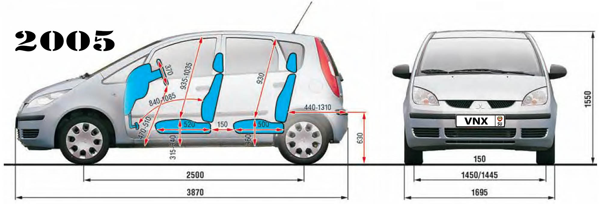
| 1 | Длина / Length | 3870 |
| 2 | Ширина (без/с зеркалами) / Width | 1695 |
| 3 | Высота (загружен/пустой) / Height | 1550 |
| 4 | Колёсная база / Wheelbase | 2500 |
| 5 | Дорожный просвет (клиренс) / Ground clearance | 150 |
| 6 | Снаряжённая масса / Total (curb) weight | 970 |
| Полная масса / Gross (max.) weight | 1450 | |
|
Двигатель / Engine |
||
| 7 | Тип / Engine Type, Code | Бензиновый, жидкостного охлаждения, четырехтактный, 3A90 |
| 8 | Количество цилиндров / Cylinder arrangement: Total number of cylinders, of valves | 3-цилиндровый, рядный, 12V, DOHC с верхним расположением двух распределительных валов |
| 9 | Диаметр цилиндра / Bore | 75.0 мм |
| 10 | Ход поршня / Stroke | 84.8 мм |
| 11 | Объём / Engine displacement | 1124 см³ |
| 12 | Система питания / Fuel supply, Aspiration | Распределенный впрыск топлива |
| Атмосферный | ||
| 13 | Степень сжатия / Compression ratio | 10.5:1 |
| 14 | Максимальная мощность / Max. output power kW (HP) at rpm | 55 кВт (75 л.с.) при 6000 об/мин |
| 15 | Максимальный крутящий момент / Max. torque N·m at rpm | 100 Нм при 3500 об/мин |
|
Трансмиссия / Transmission |
||
| 16 | Сцепление / Clutch type | 200×140 мм Однодисковое, сухое, с диафрагменной нажимной пружиной и гасителем крутильных колебаний, постоянно замкнутого типа |
| 17 | КПП / Transmission type | F5MGA МКПП 5 пятиступенчатая механическая, двухвальная, с синхронизаторами на всех передачах переднего хода |
О Книге
- Название: Mitsubishi Colt/ Colt CZ3/ Colt CZT Руководство по ремонту и эксплуатации
- Бензиновые двигатели: 3A90 1.1 л (1124 см³) 75 л.с./55 кВт, 4G19 1.3 л (1343 см³) 90 л.с./66 кВт, 4А90 1.3 л (1332 см³) 92-95 л.с./68-70 кВт, 4G15/4G15T 1.5 л (1468 см³) 98-110-150-154-166 л.с./72-81-110-113-122 кВт, 4А91 1.5 л (1499 см³) 105-106-109-111 л.с./77-78-80-81 кВт и дизельными OM639 1.5 л (1493 см³) 68-95 л.с./50-70 кВт
- Выпуск с 2002 года
- Серия: «Золотая»
- Год издания: 2010
- Автор: Коллектив авторов
- Издательство: «Ассоциация независимых издателей»
- Формат: PDF
- Страниц в книге: 292
- Размер: 50.99 МБ
- Язык: Русский
- Количество электросхем: 27
- Manuals
- Brands
- Mitsubishi MOTORS Manuals
- Automobile
- Colt 2007
- Owner’s manual
-
Contents
-
Table of Contents
-
Bookmarks
Related Manuals for Mitsubishi MOTORS Colt 2007
Summary of Contents for Mitsubishi MOTORS Colt 2007
-
Page 1
OWNER’S MANUAL English English… -
Page 2
Unleaded petrol octane rating (DIN51607) indicates a strong possibility of severe personal injury or 95 RON or higher Fuel MITSUBISHI MOTORS Europe B.V. reserves the right to death if instructions are not followed. Fuel requirements make changes relating to design and specifications and/or to… -
Page 3
Table of contents Overview General information Locking and unlocking Seat and seat belts Instruments and controls Starting and driving For pleasant driving For emergencies Vehicle care Maintenance Specifications… -
Page 4
Overview Instruments and Controls E00100102687 Instruments P. 3-2 Windscreen wiper and washer switch P. 3-39 Combination headlamps and dipper Rear window wiper and washer switch switch P. 3-31 P. 3-44 Turn-signal lever P. 3-36 Headlamp levelling switch P. 3-34 Steering wheel remote control switch* P. -
Page 5
Overview Instruments P. 3-2 Windscreen wiper and washer Combination headlamps and dipper switch P. 3-39 switch P. 3-31 Rear window wiper and washer Turn-signal lever P. 3-36 switch P. 3-44 Headlamp levelling switch P. 3-34 Ignition switch P. 4-14 Steering wheel remote control switch* P. -
Page 6
Overview Supplemental restraint Audio* system (SRS) — air bag* Hazard warning flasher switch P. 5-24, 5-24 (for front passenger’s seat) P. 3-37 P. 2-47 Multi centre display P. 3-14 Heater* P. 5-7 Automatic air conditioning* P. 5-13 Front passenger’s air bag off indicator lamp* P. -
Page 7
Overview Supplemental restraint Audio* system (SRS) — air bag* Hazard warning flasher switch P. 5-24, 5-24 (for front passenger’s seat) P.3-37 P. 2-47 Multi centre display P.3-14 Heater* P.5-7 Automatic air conditioning* P. 5-13 Front passenger’s air bag off indicator lamp* P. -
Page 8
Overview Interior E00100201984 LHD (3-door models) Lock switch P.1-20 Fuel tank filler door release lever P. 3 Electric window control Sun visors Vanity mirror Room lamp/Map lamps switch P. 1-18 P. 5-59 P. 5-60 P. 5-62 Seat belts Adjustable seat belt anchor P. -
Page 9
Overview RHD (3-door models) Lock switch P. 1-20 Fuel tank filler door release lever P. 3 Electric window control Sun visors switch P. 1-18 Room lamp/Map lamps Vanity mirror P. 5-59 P. 5-62 P. 5-60 Adjustable seat belt anchor Seat belts P. 2-22 Inside rear-view mirror (for front seats) P. -
Page 10
Overview LHD (5-door models) Lock switch P. 1-20 Fuel tank filler door release lever P. 3 Electric window control Vanity mirror Sun visors switch P. 1-18 P. 5-60 Room lamp/Map lamps P. 5-59 P. 5-62 Seat belts Adjustable seat belt anchor P.2-22 (for front seats) P. -
Page 11
Overview RHD (5-door models) Lock switch P. 1-20 Fuel tank filler door release lever P. 3 Electric window control Sun visors switch P. 1-18 Room lamp/Map lamps Vanity mirror P. 5-59 P. 5-62 P. 5-60 Seat belts P. 2-22 Adjustable seat belt anchor Inside rear-view mirror (for front seats) P. -
Page 12
Overview Luggage area (Except for vehicle with compact spare wheel) E00100400846 3-door models Luggage compartment lamp P. 5-63 Tyre repair kit P. 6-11 Towing hook P. 6-11… -
Page 13
Overview 5-door models Luggage compartment lamp P. 5-63 Tyre repair kit P. 6-11 Luggage hooks Luggage hooks (floor)* P. 5-72 (floor)* P. 5-72 Towing hook P. 6-11 AF5000747… -
Page 14
Overview Luggage area (Vehicle with compact spare wheel) E00100400859 3-door models Luggage compartment lamp P. 5-63 Towing hook P. 6-11 Spare wheel P. 6-25 Jack P. 6-21 Wheel nut wrench P. 6-11… -
Page 15
Overview 5-door models Luggage compartment lamp P. 5-63 Towing hook P. 6-11 Wheel nut wrench P. 6-11 Spare wheel P. 6-25 Luggage hooks Luggage hooks (floor)* P. 5-72 (floor)* P. 5-72 Jack P. 6-21… -
Page 16
Overview Exterior E00100502157 3-door models Electric window control P. 1-18 Windscreen wipers P. 3-39 Outside rear-view mirrors P. 4-10 Fuel tank filler P. 3 Bonnet P. 8-4 Locking and unlocking P. 1-7 Keyless entry system* P. 1-5 Side turn-signal lamps P. -
Page 17
Overview 3-door models Antenna P. 5-59 High-mounted stop lamps P. 8-63 Stop and tail lamps P. 8-57 Rear window wiper and washer P. 3-44 Rear fog lamp (LHD vehicles) Rear turn-signal lamps P. 3-38, 8-62 P. 3-36, 8-57 Reversing lamp Reversing lamp (LHD vehicles) (RHD vehicles) P.8-62… -
Page 18
Overview 5-door models Electric window control P. 1-18 Windscreen wipers P.3-39 Outside rear-view mirrors P. 4-10 Bonnet P. 8-4 Fuel tank filler P. 3 Locking and unlocking P. 1-7 Keyless entry system* P. 1-5 Side turn-signal lamps P. 3-36, 8-49 Headlamps, low beam P. -
Page 19
Overview 5-door models Antenna P. 5-59 High-mounted stop lamps P. 8-63 Stop lamps P. 8-57 Rear turn-signal lamps P. 3-36, 8-57 Rear window wiper and washer P. 3-44 Reversing lamps P. 8-57 Rear fog lamp/Tail lamps Tail lamps (LHD vehicles) (LHD vehicles) P. -
Page 21: Table Of Contents
General information Fuel selection ……Filling the fuel tank ……Installation of accessories .
-
Page 22: Fuel Selection
If the check engine warning lamp flashes, have the system ● Diesel-powered vehicles are designed to use only die- checked as soon as possible at a MITSUBISHI MOTORS sel fuel that meets the EN 590 standard. Authorized Service Point.
-
Page 23: Filling The Fuel Tank
General information Filling the fuel tank Fuel tank capacity 47 litres E00200201347 Refueling WARNING 1. Before filling with fuel, stop the engine. ● Gasoline is highly flammable and explosive. You 2. The fuel tank filler is located on the rear left side of your could be burned or seriously injured when handling vehicle.
-
Page 24
General information 3. Open the fuel tank filler tube by slowly turning the cap anticlockwise. A- Remove B- Close CAUTION ● As the fuel system may be under pressure, remove the fuel tank filler tube cap slowly. This will relieve any pressure or vacuum that might have built up in the fuel tank. -
Page 25: Installation Of Accessories
Do not tilt the gun. Insert the E00200300413 gun in the tank port as far as it will go. We recommend you to consult your MITSUBISHI MOTORS Authorized Service Point. CAUTION ● The installation of accessories, optional parts, should only be carried out within the limits prescribed by law in your ●…
-
Page 26: Modification/Alterations To The Electrical Or Fuel Systems
E00200400267 not only for MITSUBISHI MOTORS, but also a MITSUBISHI MITSUBISHI MOTORS has always manufactured safe, high MOTORS Authorized Service Point, to check whether the quality vehicles. In order to maintain this safety and quality, it…
-
Page 27: Genuine Parts
General information Genuine parts Used engine oils safety instructions and disposal information E00200500486 MITSUBISHI MOTORS has gone to great lengths to bring you E00200600025 a superbly crafted automobile offering the highest quality and dependability. WARNING Use MITSUBISHI MOTORS Genuine Parts, designed and ●…
-
Page 29
Locking and unlocking Keys ……..1- Electronic immobilizer (Anti-theft starting system). -
Page 30: Keys
Locking and unlocking Keys • Do not expose to water. • Keep away from magnetic key holders. E00300101220 • Keep away from audio systems, personal cumputers, The keys fit all locks. TVs, and any other equipment that generates a magnetic field.
-
Page 31: Electronic Immobilizer (Anti-Theft Starting System)
Locking and unlocking Electronic immobilizer The immobilizer indicator lamp comes on if there is a malfunc- tion in the system electronics. (Anti-theft starting system) E00300201016 The electronic immobilizer is designed to significantly reduce vehicle theft. The purpose of the system is to immobilize the vehicle if an invalid start is attempted.
-
Page 32
Locking and unlocking NOTE ● In the following cases, the vehicle may not be able to receive the registered ID code from the key. This means that the engine will not start even when the registered key is turned to the “START” position. •… -
Page 33: Keyless Entry System
● If you lose your key, you can order a new one from your E00300301352 MITSUBISHI MOTORS Authorized Service Point. Press the remote control switch to lock or unlock all the doors To obtain a replacement or additional spare key, take your and the tailgate.
-
Page 34
For further information, contact your MITSUBISHI remote control switch, the battery may have run down. MOTORS Authorized Service Point. Have the battery replaced by a MITSUBISHI MOTORS • The time from pressing of the UNLOCK switch (2) to Authorized Service Point. -
Page 35: Doors
Locking and unlocking Doors To lock or unlock from inside the vehicle E00300401412 CAUTION ● Make sure the doors are closed: driving with doors incompletely closed is dangerous. ● Never leave children in the vehicle unattended. ● Take care not to lock the doors while the key is inside the vehicle.
-
Page 36
Locking and unlocking To lock without using the key Rear door (5-door models) Front passenger’s door Set the inside lock knob (1) to the locked position, and close the door (2). NOTE ● The driver’s door cannot be locked using the inside lock knob while the driver’s door is open. -
Page 37: Central Door Locks
Locking and unlocking Central door locks Front doors with key Turn the key in the driver’s door towards the front of the vehi- E00300800901 cle to lock the doors and the tailgate and towards the rear of the NOTE vehicle to unlock the doors and the tailgate. ●…
-
Page 38: Dead Lock System
Locking and unlocking Driver’s door with inside lock knob Dead Lock System Set the inside lock knob on the driver’s door towards the front E00305100013 The Dead Lock System helps to prevent theft. When the key- of the vehicle to lock the doors and the tailgate. Set it towards less entry system has been used to lock all of the doors and the the rear of the vehicle to unlock the doors and the tailgate.
-
Page 39
The hazard warning lamps will flash three times to show tion confirmation function causes the hazard warning that the Dead Lock System has been set. lamps to flash for confirmation of system operation. For details, please contact a MITSUBISHI MOTORS Authorized Service Point. 1-11… -
Page 40
Locking and unlocking Cancelling the system ● Even when it is not possible to use the keyless entry sys- tem to unlock the doors, it is possible to use the key to E00305300031 When the UNLOCK switch (B) of the keyless entry system is unlock a door. -
Page 41: Child-Protection» Rear Doors (5-Door Models)
Locking and unlocking “Child-protection” rear doors CAUTION (5-door models) ● When driving with a child in the rear seat, please E00300900348 use the child protection to prevent accidental door opening, which may cause an accident. 1- Lock 2- Free Child protection helps prevent doors from being opened acci- dentally, especially when small children are in the rear seat.
-
Page 42: Tailgate
Locking and unlocking Tailgate To lock or unlock from outside the vehicle (except for vehicles with keyless entry system) E00301400698 WARNING 3-door models ● It is dangerous to drive with the tailgate open as car- bon monoxide (CO) gas can enter the cabin. You cannot see or smell CO.
-
Page 43
Locking and unlocking To lock or unlock from inside the vehicle 5-door models On vehicles with central door lock system, the tailgate can be locked or unlocked by using the inside lock knob (driver side), regardless of the position of the ignition key. 1- Insert (or remove) the key 2- Unlock 3- Lock… -
Page 44
Locking and unlocking To open To close Pull the tailgate lever upwards to open the tailgate. Pull the tailgate grip (A) downwards as illustrated and release it before the tailgate closes completely. Gently slam the tailgate shut from the outside so that it is completely closed. CAUTION ●… -
Page 45: Manual Window Control (5-Door Models, Rear Door Window Only)
Locking and unlocking Manual window control NOTE ● Gas struts (B) are installed in the locations illustrated to (5-door models, rear door window only) support the tailgate. Please observe the following in order E00302100083 to prevent damage or faulty operation. •…
-
Page 46: Electric Window Control
Locking and unlocking Electric window control E00302200042 The electric windows can only be operated with the ignition switch in the “ON” position. Electric window control switch E00302300968 Each door window opens or closes while the corresponding switch is operated. 1- Driver’s door window 2- Front passenger’s door window 3- Rear left door window (5-door models)* 4- Rear right door window (5-door models)*…
-
Page 47
Locking and unlocking Passenger’s switches NOTE ● Repeated operation with the engine stopped will run down The passenger’s switches can be used to operate the corre- the battery. Operate the window switches only while the sponding passenger’s door windows. engine is running. Press the switch down to open the window, and pull the switch up to close it. -
Page 48
Locking and unlocking Lock switch E00303100413 When this switch is operated, the passenger’s switches cannot be used to open or close the door windows and the driver’s switch cannot open or close any door windows other than the driver’s door windows. To unlock, press it once again. -
Page 49
Seat and seat belts Seat……..2- Seat arrangement . -
Page 50: Seat
Seat and seat belts Seat E00400101003 1-Front seat 2-Rear seat ● To adjust forward or backwards → P. 2-5 ● To adjust forward or backward → P. 2-9 ● To recline the seatback → P. 2-5 ● To recline the seatback → P. 2-10 ●…
-
Page 51: Seat Arrangement
Seat and seat belts Seat arrangement E00400200443 The seats can be operated for the desired seat arrangement. Normal usage Folding the seatbacks forward (5-door models, full flat folding) → P. 2-13 Folding the rear seat* → P. 2-15 How to stow large articles Removing the rear seat (5-door mod- els, separated seat only)* →…
-
Page 52: Seat Adjustment
Seat and seat belts Seat adjustment WARNING E00400300415 ● To minimize the risk of personal injury in the event Adjust the driver’s seat so that you are comfortable and can of a collision or sudden braking, the seatbacks reach the pedals, steering wheel, switches etc. while retaining a should always be in the almost upright position clear field of vision.
-
Page 53: Front Seat
Seat and seat belts Front seat To recline the seatback E00400600623 E00400400012 In order to recline the seatback, lean forward slightly, pull the To adjust forward or backward seatback lock lever up, and then lean backward to the desired E00400500505 position and release the lever.
-
Page 54
Seat and seat belts To adjust seat height* To get in and out of the rear seat (3-door models) E00400700578 E00401000060 Adjust the seat height by repeatedly operating the lever. The lever (A) can be used to make getting in and out easier. Fold the seatback forward, then slide the entire seat forward. -
Page 55
Seat and seat belts Heated seats* CAUTION E00401100162 The heated seats can be operated with the ignition switch in the ● The reclining mechanism of the seatback is spring “ON” position. loaded, causing it to return to the vertical position when the lock lever is operated. -
Page 56: Rear Seat
Seat and seat belts Rear seat* CAUTION E00401300207 ● If the following types of persons use the heated seats, they might become too hot or receive minor burns WARNING (red skin, heat blisters, etc.): ● When a person is sitting in the rear seats, pull up the •…
-
Page 57
Seat and seat belts To adjust forward or backward Separated seat (5-door models)* E00401400064 Pull the seat adjusting lever and adjust the seat forward or backward to the desired position. After adjustment, release the adjusting lever to lock the seat in position. Bench seat* WARNING ●… -
Page 58: Head Restraints
Seat and seat belts To recline the seatback Head restraints E00401500241 E00403300966 In order to recline the seatback, lean forward slightly, push the WARNING seatback lock knob (A) down, and then lean backward to the desired position and release the knob. The seatback will lock in ●…
-
Page 59
Seat and seat belts To adjust height To remove Adjust the head restraint height so that the centre of the Lift the head restraint with the height adjusting knob (A) restraint is as close as possible to eye level to reduce the pushed in. -
Page 60: Making A Luggage Area
Seat and seat belts Making a luggage area CAUTION E00403400215 ● Confirm that the height adjusting knob (A) is cor- WARNING rectly adjusted as shown in the illustration, and also lift the head restraints to ensure that they do not ●…
-
Page 61
Seat and seat belts Folding the seatback forward (full flat folding) Front seat (5-door models) E00403500304 To fold Larger objects can be loaded into the vehicle if a seatback is Pull the seatback lock lever and fold the seatback forward until folded forward. -
Page 62
Seat and seat belts Rear seat To replace 1. Push the seatback lock knob (A) down and raise the seat- To fold back until it locks securely into place. Push the seatback lock knob (A) down and fold the seatback forward until it is held securely. -
Page 63
Seat and seat belts Folding the rear seat* 4. Pull up the lock release lever (A) at the back of the seat cushion. With the lock release lever still pulled, lift the E00403700250 To create luggage space, you can fold the rear seat. whole seat forward. -
Page 64
Seat and seat belts CAUTION Separated seat (5-door models)* ● Do not slide the rear seat while pulling the lock release lever. This may bend the fittings of the lock mechanism, which may prevent unlocking. 5. Securely retain the rear seat by hooking the retaining bands onto the head restraints of the front seats. -
Page 65
Seat and seat belts To return Separated seat (5-door models)* 1. Remove the retaining bands while supporting the seat by hand. Store the retaining bands in their original positions, then gently lower the seat. Bench seat* 2. Push the seat downward until it clicks into place. Then check that the seat is securely locked in position by trying to lift the back of the seat cushion. -
Page 66
Seat and seat belts 3. Adjust the seat’s fore-aft position as desired, then push Separated seat (5-door models)* down the seatback locking lever and raise the seatback until it locks. Push lightly on the seat to confirm that it has been securely retained. -
Page 67
Seat and seat belts Removing the rear seat 4. Pull up the lock release lever (A) at the back of the seat cushion. With the lock release lever still pulled, lift the (5-door models, separated seat only) whole seat forward. E00410500032 To create more luggage space, you can remove the rear seat. -
Page 68
Seat and seat belts 5. Pull the rear seat lock knob (B) to unlock the rear seat, To refit then lift the rear seat to remove it. 1. Fit the rear seat mounting (A) onto the retaining bar (B), then tilt the rear seat lock knob (C) and check that the hook is securely attached to the retaining bar. -
Page 69
Seat and seat belts 2. Gently tip the seat while supporting it by hand. Push the 3. Adjust the seat’s fore-aft position as desired, then push entire seat downward until it clicks into place. Check that down the seatback locking lever and raise the seatback the seat is securely locked in position by trying to lift the until it locks. -
Page 70: Seat Belts
Seat and seat belts Seat belts WARNING E00404800607 ● Always place the shoulder belt over your shoulder To protect you and your passengers in the event of an accident, and across your chest. Never put it behind you or it is important that the seat belts are worn correctly while driv- under your arm.
-
Page 71
Seat and seat belts 3-point type seat belt WARNING (with emergency locking mechanism) ● Never hold a child in your arms or on your lap when E00404900406 travelling in this vehicle, even if you are wearing This type of belt requires no length adjustment. Once worn, the your seat belt. -
Page 72
Seat and seat belts To unfasten CAUTION Hold the latch plate and push the button on the buckle. ● Never wear the lap portion of the belt across your abdomen. During accidents it can press sharply against abdomen and increase the risk of injury. ●… -
Page 73
Seat and seat belts Seat belt reminder/warning lamp* When the ignition key is turned to the “ON” position, the warn- ing lamp will come on and a tone will sound for about 6 sec- E00409800208 A tone and warning lamp are used to remind the driver and onds. -
Page 74
Seat and seat belts Adjustable seat belt anchor (front seats) Rear-centre 3-point type seat belt (5-door models) E00405000055 The seat belt anchor height can be adjusted. E00405200031 Move the seat belt anchor down with the lock knob (A) The rear-centre 3-point type seat belt must be worn correctly as depressed. -
Page 75
Seat and seat belts To fasten 2. Pull the seat belt and insert the latch plate (A) into the black buckle (D). 1. Pass the seat belt through the seat belt guide (C). 3. Insert the latch plate (B) into the red buckle (E). 4. -
Page 76
Seat and seat belts To unfasten To store 1. Hold the latch plate (B) and push the button (F) on the red When the rear-centre 3-point type seat belt is not being used, buckle. insert the latch plate (A) into the holder (H) and stow the 2. -
Page 77: Pregnant Women Restraint
Seat and seat belts Pregnant women restraint Seat belt pre-tensioner system and force limiter system E00405600136 WARNING E00405700010 The driver’s seat and front passenger’s seat each have a seat belt equipped with a pre-tensioner system. ● Seat belts work for everyone, including pregnant women.
-
Page 78
● If you need to scrap the vehicle, please consult a MITSUBISHI MOTORS Authorized Service Point. It is important to do so because unexpected activa- tion of the pre-tensioner seat belts could cause injury. -
Page 79: Child Restraint
Seat and seat belts Child restraint Caution for installing the child restraint on vehicle with front passenger air bag E00406401239 When transporting children in your vehicle, some type of child The label shown here is attached on vehicles with a front pas- restraint system should always be used according to the size of senger air bag.
-
Page 80
Seat and seat belts NOTE WARNING [Vehicles with front passenger’s air bag ON-OFF switch] ● A REARWARD FACING CHILD RESTRAINT ● If you have a rearward facing child restraint system that must NOT be used in the front passenger seat if the cannot be fitted to any seat other than the front passenger front passenger’s air bag has not been deactivated. -
Page 81
Seat and seat belts Infants and small children WARNING E00406600393 When transporting infants and small children in your vehicle, ● A FORWARD FACING CHILD RESTRAINT follow the instruction given below. should be used in the rear seat whenever possible; if used in the front seat, adjust the seat to the most rearward position. -
Page 82
Seat and seat belts ● Before purchasing a child restraint system, try installing it NOTE in the rear seat to make sure there is a good fit. Because of ● Depending on the seating position in the vehicle and the the location of the seat belt buckles and the shape of the child restraint system that you have, the child restraint can seat cushion, it may be difficult to securely install some… -
Page 83
Seat and seat belts Older children E00406700017 Children who have outgrown the child restraint system should be seated in the rear seat and wear combination lap shoulder belt. The lap portion of the belt should be snug and positioned low on the abdomen so that it is below the top of the hip-bone. -
Page 84
● U — Suitable for “universal” category restraints approved for use in this mass group. ● UF — Suitable for forward-facing “universal” category restraints approved for use in this mass group. ● L — Suitable for particular child restraints (MITSUBISHI MOTORS genuine parts). ● B — Built-in restraint approved for this mass group. -
Page 85
● The above suitability table applies to retention of child restraints using seat belts. ● When MITSUBISHI MOTORS genuine part No. MZ313200 is used on the rear seat, it can also be retained by means of ISO- FIX child restraint mountings. -
Page 86
● U — Suitable for “universal” category restraints approved for use in this mass group. ● UF — Suitable for forward-facing “universal” category restraints approved for use in this mass group. ● L — Suitable for particular child restraints (MITSUBISHI MOTORS genuine parts). ● B — Built-in restraint approved for this mass group. -
Page 87
● The above suitability table applies to retention of child restraints using seat belts. ● When MITSUBISHI MOTORS genuine part No. MZ313200 is used on the rear seat, it can also be retained by means of ISO- FIX child restraint mountings. -
Page 88
ISOFIX mountings. It is not necessary to retain the child restraint system using the vehicle’s seat belts. Only a MITSUBISHI MOTORS genuine child restraint system can be used. Genuine parts No. : MZ313200 ECE No. -
Page 89
“To adjust forward or backward” on page 2-9.) MITSUBISHI MOTORS genuine one is used, it may 2. Push the child restraint system’s connectors (A) into the not be properly retained and the child could be seri- slit (B) in accordance with the instructions provided by ously injured as a result. -
Page 90
Seat and seat belts Installing a child restraint system to a 3-point 3. Push and pull the child restraint system in all directions to be sure it is firmly secured. type seat belt (with emergency/automatic locking mechanism) WARNING E00407000411 The 3-point type seat belts at the rear seating position can be ●… -
Page 91
Seat and seat belts To install 3. To activate the ALR mode, slowly pull the shoulder part of the belt all the way out until it stops, then let the belt 1. Place the child restraint system in the rear seating position feed back into the retractor. -
Page 92
Seat and seat belts 5. After confirming that the belt is locked, grab the shoulder WARNING part of the belt near the buckle and pull up to remove any slack from the lap part of the belt. Remember, if the lap ●… -
Page 93
Seat and seat belts Installing a child restraint system to a 5-door models 3-point type seat belt (with emergency locking mechanism) E00408700301 For safety, you are advised to install the child restraint system using a 3-point type seat belt with emergency/automatic lock- ing mechanism. -
Page 94: Seat Belt Inspection
● Do not attempt to repair or replace any part of the seat belt assemblies; we recommend that you have this work done by a MITSUBISHI MOTORS Authorized Service Point. Incorrect repair or replacement could reduce the effectiveness of the belts and could result in serious injury in the event of a collision.
-
Page 95: Supplemental Restraint System (Srs) — Air Bag
Seat and seat belts Supplemental restraint system WARNING (SRS) — air bag ● IT IS VERY IMPORTANT ALWAYS TO WEAR E00407201436 YOUR SEAT BELT CORRECTLY, EVEN IF AN The information contained in this supplemental restraint sys- AIR BAG IS FITTED: tem (SRS) section covers important points concerning the •…
-
Page 96
Seat and seat belts WARNING WARNING ● IT IS VERY IMPORTANT TO BE PROPERLY ● Do not sit on the edge of the seat, or lean head or SEATED. chest close to the steering wheel or instrument panel. A driver or front passenger too close to the steering Do not put feet or legs on or against the instrument wheel or instrument panel during air bag deploy- panel. -
Page 97
Seat and seat belts WARNING WARNING ● Infants and small children should never be unre- ● A REARWARD FACING CHILD RESTRAINT strained, stand up against the instrument panel or must NOT be used in the front passenger seat if the held in your arms or on your lap. -
Page 98
Seat and seat belts NOTE WARNING [Vehicles with front passenger’s air bag ON-OFF switch] ● If you have a rearward facing child restraint system that ● A FORWARD FACING CHILD RESTRAINT cannot be fitted to any seat other than the front passenger should be used in the rear seat whenever possible;… -
Page 99
Seat and seat belts Caution for installing the child restraint on How the supplemental restraint system works vehicle with front passenger air bag E00407300166 The SRS includes the following components: The label shown here is attached to vehicles with a front pas- senger air bag. -
Page 100
Seat and seat belts When the impact sensors detect an impact of sufficient frontal or side force, an automated circuit ignites materials in the infla- tor to generate gas and inflate the air bags. The deployment of the air bags produces a sudden, loud noise, and releases some smoke and powder, but these conditions are not injurious and do not indicate a fire in the vehicle. -
Page 101
Seat and seat belts Front passenger’s air bag ON-OFF switch* WARNING E00410100139 The front passenger’s air bag ON-OFF switch can be used to ● To reduce the risk of serious or fatal injury: disable the front passenger’s air bag. If you have a rearward •… -
Page 102
Seat and seat belts To turn an air bag off The air bag will remain OFF, and will NOT deploy, until it is turned ON again. E00410600121 To turn an air bag off, follow these steps: 1. Insert the key into the key opening of the air bag ON-OFF WARNING switch, push the key inwards until stopped by a touch and ●… -
Page 103
Seat and seat belts To turn an air bag on The air bag will remain ON, and will be ready to deploy, until it is turned OFF again. E00410700092 To turn an air bag on, follow these steps: 1. Insert the key into the key opening of the air bag ON-OFF WARNING switch, push the key inwards until stopped by a touch and ●… -
Page 104
When the front passenger’s air bag ON-OFF switch is turned MITSUBISHI MOTORS Authorized Service Point ON, the indicator goes off to show that the front passenger’s air as soon as possible. -
Page 105
Seat and seat belts Driver’s and passenger’s front air bag system E00407400213 The driver’s air bag is located under the padded cover in the middle of the steering wheel. The front passenger’s air bag is contained in the instrument panel above the glove box. The driver’s air bag and the front passenger’s air bag are designed to inflate at the same time even if the passenger seat is not occupied. -
Page 106
Seat and seat belts Deployment of front air bags E00407501077 The front air bags ARE DESIGNED TO DEPLOY when… A head-on collision with a solid wall at a speed of Moderate to severe frontal impact within the shaded approximately 25 km/h (16 mph) or higher area between the arrows The front air bags are designed to deploy when the vehicle suf- As frontal collisions can easily move you out of position, it is… -
Page 107
Seat and seat belts The front air bags MAY NOT DEPLOY when… Collision with a utility pole, tree or other narrow objects In certain types of frontal collisions; the vehicle’s body struc- ture is designed to absorb a shock to help protect the occupants from harm. -
Page 108
Seat and seat belts The front air bags ARE NOT DESIGNED TO Rear end collisions DEPLOY when… The front air bags are not designed to deploy in conditions where they cannot typically provide protection to the occupant. Such conditions are shown in the illustration. Because the front air bags do not protect the occupant in all types of collisions, make sure that you always wear your seat belt correctly. -
Page 109
Seat and seat belts The front air bags MAY DEPLOY when… Collision with an elevated median/island or kerb The front air bags may deploy if the bottom of the vehicle suf- fers a moderate to severe impact (undercarriage damage). Examples of some typical conditions are shown in the illustra- tion. -
Page 110
Once the air bags have been deployed, they will not work again. They must be replaced promptly, and we recommend that you have the entire air bag sys- tem inspected by a MITSUBISHI MOTORS Authorized Service Point. WARNING ● Do not attach accessories to, or put them in front of, the windscreen. -
Page 111
Seat and seat belts Side air bag system* The label shown here is attached to the seatbacks with a side air bag. E00407600084 The side air bags (A) are contained in the driver and front pas- senger seatbacks. The side air bag is designed to inflate only on the side of the vehicle that is impacted, even with no passenger in the front seat. -
Page 112
Seat and seat belts Curtain air bag system* Deployment of side air bags and curtain air bags E00409100067 E00407700652 The curtain air bags are contained in the front pillars, rear pil- The side air bags and curtain air bags ARE lars and roof side rail. -
Page 113
Seat and seat belts The side air bags and curtain air bags MAY NOT Side impacts in an area away from the passenger compart- DEPLOY when… ment In certain types of side collisions, the vehicle’s body structure is designed to absorb the shock to help protect the occupants from harm. -
Page 114
Seat and seat belts The side air bags and curtain air bags ARE NOT Oblique side impacts DESIGNED TO DEPLOY when… The side air bags and curtain air bags are not designed to deploy in conditions where they cannot usually provide protec- tion to the occupant. -
Page 115
Seat and seat belts Because the side air bags and curtain air bags do not protect the WARNING occupant in all types of collisions, be sure always to wear your seat belts properly. ● The side air bags and curtain air bags inflate with great force. -
Page 116
Seat and seat belts WARNING WARNING ● Do not allow a child to kneel on the passenger seat ● Do not allow any rear seat occupant to hold onto the facing the passenger’s side door, since the side air seatback of either front seat, in order to reduce the bags and curtain air bags inflate with great force. -
Page 117
● We recommend work around and on the side air bags and curtain air bags system to be carried out by a MITSUBISHI MOTORS Authorized Service Point. Improper work could result in inadvertent deployment of side air bags and curtain air bags, or could render side air bags and curtain air bags inop- erative;… -
Page 118
When the ignition key is turned properly, and we recommend you to have it to the “ON” or “START” position, the warning lamp should inspected by a MITSUBISHI MOTORS Authorized illuminate for several seconds and then should go out. This Service Point immediately. -
Page 119
● If you junk or scrap the vehicle, we urge you to first take near the components of the SRS to be performed by the vehicle to a MITSUBISHI MOTORS Authorized a MITSUBISHI MOTORS Authorized Service Service Point so that the SRS can be rendered safe. -
Page 121
Instruments and controls Instruments…….3- Indicator and warning lamps ….3- Indicator lamps. -
Page 122: Instruments
Instruments and controls Instruments E00500100384 1- Fuel gauge 2- Speedometer 3- Tachometer 4- Odometer/Tripmeter 5- Tripmeter reset button…
-
Page 123
Instruments and controls Speedometer Indication for km/h and mph The speedometer indicates the vehicle’s speed in miles per E00500200516 hour (mph) and kilometers per hour (km/h). Indication for km/h The speedometer indicates the vehicle’s speed in kilometers per hour (km/h). -
Page 124
Instruments and controls Tachometer Odometer/Tripmeter E00500300142 E00500600060 The tachometer indicates the engine speed (r/min). The When the ignition switch is in the “ON” position, odometer tachometer can help you obtain more economical driving and and tripmeter indications are given. also warns you of excessive engine speeds. A- Odometer B- Tripmeter CAUTION… -
Page 125
Instruments and controls Tripmeter To reset the tripmeter To return the display to “0”, press the reset button (C) for more The tripmeter indicates the distance travelled during a particu- than 1 second. Only the currently displayed value will be reset. lar trip or period. -
Page 126
Instruments and controls Fuel gauge Low fuel warning lamp E00508100117 E00500700162 If the remaining fuel level becomes low with the ignition The fuel gauge indicates the fuel level in the fuel tank when the switch in the “ON” position, the low fuel warning lamp (A) ignition switch is in the “ON”… -
Page 127: Indicator And Warning Lamps
Instruments and controls Indicator and warning lamps E00501501324 13- Traction control system (TCL)/Active stability control sys- 1- Electric power steering warning lamp → P. 4-41 tem (ASC) indicator lamp* → P. 4-44 2- Supplemental restraint system (SRS) warning lamp → 14- Seat belt warning lamp* →…
-
Page 128: Indicator Lamps
Instruments and controls Indicator lamps Rear fog lamp indication lamp E00502000084 E00501600012 This indication lamp illuminates while the rear Turn-signal indicator lamps/Hazard fog lamp is on. warning indicator lamps E00501700042 These indicator lamps blink on and off when a Low coolant temperature indicator turn-signal lamp is operating.
-
Page 129: Warning Lamps
Instruments and controls Diesel preheat indication lamp Warning lamps (diesel-powered vehicles) E00502400017 Brake warning lamp E00502300029 This indication lamp illuminates when the igni- E00502501099 tion switch is placed in the “ON” position. As This lamp illuminates when the ignition switch the glow plug becomes hot, the lamp goes out is turned to the “ON”…
-
Page 130
Avoid hard braking and high- speed driving. Stop the vehicle in a safe place and we recommend you consult a MITSUBISHI MOTORS Authorized Service Point. 3-10… -
Page 131
Instruments and controls Check engine warning lamp CAUTION E00502600918 ● If the lamp illuminates while the This lamp is a part of an onboard diagnostic sys- engine is running, avoid driving at tem which monitors the emissions, engine and high speeds and we recommend you to automated manual transmission control systems. -
Page 132
Instruments and controls Charge warning lamp Oil pressure warning lamp E00502700036 E00502800053 This lamp illuminates when the ignition switch This lamp illuminates when the ignition switch is turned to the “ON” position, and the lamp goes is turned to the “ON” position, and the lamp goes off after the engine has started. -
Page 133
Instruments and controls High coolant temperature warning Door-ajar warning lamp lamp E00503300215 This lamp illuminates when a door or the tailgate E00503000023 is either open or incompletely closed. This lamp illuminates and a buzzer sounds if the A buzzer sounds if the vehicle speed exceeds coolant temperature becomes excessively high. -
Page 134: Multi-Centre Display
Instruments and controls Multi-centre display E00503600061 WARNING ● When operating the system for a prolonged period, make sure the vehicle is parked in a well ventilated area to avoid the accumulation of toxic fumes inside and outside of the passenger compartment. CAUTION ●…
-
Page 135
Instruments and controls A- Outside temperature → P. 3-19 B- Driving information → P. 3-20 C- Digital clock → P. 3-16 NOTE ● The display unit (ex. km or mile) and brightness can be changed as desired. (Refer to “ Display brightness adjustment” on page 3-26 and “Display unit selection”… -
Page 136
1. Enter the function setup mode by pushing the “MENU” button. Following modes are available for digital clock adjustment: ● For vehicles with MITSUBISHI MOTORS genuine audio automatic mode and manual mode ● Except for vehicles with MITSUBISHI MOTORS genu-… -
Page 137
Instruments and controls 2. Press the “MENU” button repeatedly to select the CT NOTE ● Although “PH” and “MUTE” appear on the display, the (Clock Time) mode. The order is: AF → CT → REG → TP-S → PH → MUTE PH and MUTE functions are inoperative. -
Page 138
Instruments and controls Automatic mode (For vehicles with MITSUBISHI 3. Make your selection by pressing the “ ” button or the MOTORS genuine audio) “ ” button. The automatic mode can set the local time automatically by using the signal from the local RDS stations. In this mode, CT (A) is shown in the display. -
Page 139
Instruments and controls Outside temperature Manual mode The manual mode is also available in case the “Automatic E00503900048 This value shows the outside temperature of the vehicle. mode” shows the incorrect time when the adjacent local RDS If the outside air temperature drops below approx. 3 °C, the stations are located in a different time zone. -
Page 140
NOTE ● The outside temperature can be displayed from -40 °C to E00509000054 50 °C. For vehicles with MITSUBISHI MOTORS genuine ● The outside temperature displayed may differ from the audio actual temperature on account of surrounding conditions, The momentary fuel consumption, average fuel consumption, driving conditions, etc. -
Page 141
Instruments and controls Change of driving information Momentary fuel consumption (For vehicles with MITSUBISHI MOTORS genuine E00509200030 This value shows the momentary fuel consumption (in audio) L/100km, km/L or mpg). Calculation and indication of the E00509100055 value begin when the vehicle speed rises above 6 km/h (4 Every time the “DISP”… -
Page 142
Instruments and controls Average fuel consumption To reset the display You can switch from the automatic reset mode to the manual E00509300057 This value shows the average fuel consumption (in L/100km, reset mode by performing the following operations: km/L or mpg). 1. -
Page 143
Instruments and controls 2. The name of the newly selected mode will flash, then the 3. The status of the selected mode will be shown on the dis- display will return to its original indications. play. 1- Automatic reset mode 2- Manual reset mode 3-23… -
Page 144
Instruments and controls ● Automatic reset mode Driving range When 4 hours have passed after the ignition switch is E00509400045 This value shows the distance (in km or miles) that can be turned to the “OFF” or “ACC” position, the display is driven on the fuel remaining in the fuel tank. -
Page 145
Instruments and controls Average speed NOTE ● If the driving range drops below 50 km (30 miles) while E00509500059 This value shows the average speed (in km/h or mph) since the the driving range is displayed, the display shows “—”. display was reset. -
Page 146
Instruments and controls ● Automatic reset mode Display brightness adjustment When 4 hours have passed after the ignition switch is E00509600050 1. Press and hold down button (A), then press the “H” button turned to the “OFF” or “ACC” position, the display is (B) within 1 second. -
Page 147
Instruments and controls 2. Adjust the brightness by pressing the “H” button (B) or 3. Press the “SET” button (D) to determine the setting. The “M” button (C). display will return to the original display item. NOTE H- Increase brightness ●… -
Page 148
NOTE ● Except for vehicles with MITSUBISHI MOTORS genu- ine audio, only the unit of momentary fuel consumption can be changed to km or miles. 1. Press and hold down button (A), then press the “M” but- ton (B) within 1 second. -
Page 149
Instruments and controls 3. If the km unit was selected in step 2, the fuel consumption 4. When you have finished setting the fuel consumption unit unit must be subsequently selected using the “H” button (or if you selected miles in step 2), the system will require (C) or “M”… -
Page 150
Instruments and controls Use the “H” button (C) or “M” button (B) to choose your 5. The display will return to the original display item. desired time display format, and then press the “SET” but- NOTE ton (D) to enter the setting. ●… -
Page 151: Combination Headlamps And Dipper Switch
Instruments and controls Combination headlamps and dipper switch Type 1 Rotate the switch to turn on the lamps. E00506000923 Headlamps NOTE ● Do not leave the headlamps and other lamps on for a long time while the engine is stationary (not running). A run- down battery could result.
-
Page 152
Instruments and controls Type 2 NOTE ● If the front fog lamps (if so equipped) turn on when they Rotate the switch to turn on the lamps. are supposed to with the switch in the “AUTO” position, the lamps turn off automatically with the engine switch off. -
Page 153
Instruments and controls Lamp monitor buzzer Dipper (High/Low beam change) E00506100067 E00506200127 If the driver’s door is opened when the ignition key is in the When the lamp switch is in the “ ” position, the “LOCK” or “ACC” position or removed from the ignition beam changes from high to low (or low to high) switch while the lamps are on, a buzzer will sound to remind each time the lever is pulled to (1). -
Page 154: Headlamp Levelling Switch
Instruments and controls Headlamp flasher Headlamp levelling switch E00506300043 E00506400581 The high beams flash when the lever is pulled slightly to (2), The angle of the headlamp beam varies depending upon the and will go off when it is released. load carried by the vehicle.
-
Page 155
Instruments and controls 3-door models 5-door models Vehicle Vehicle condition condition Switch Switch “0” “2” “2” “3” “0” “2” “3” “3” position position •:1 person •:1 person :Full luggage load :Full luggage load Switch position 0 — Driver only/Driver + 1 front passenger Switch position 0 — Driver only/Driver + 1 front passenger Switch position 2 — 5 passengers (including driver) Switch position 2 — 5 passengers (including driver) -
Page 156: Turn-Signal Lever
● It is possible to change the number of times the turn-signal turn signal indicator lamp flashes. lamps flash for a lane-change. For details, we recommend you to consult a MITSUBISHI MOTORS Authorized Service Point. 1- Turn-signals When making a normal turn, use position (1). The lever will return automatically when cornering is completed.
-
Page 157: Hazard Warning Flasher Switch
Instruments and controls Hazard warning flasher switch Front fog lamp switch E00506600088 E00506800543 Use the hazard warning flasher switch when the vehicle has to The front fog lamps illuminate only when the headlamps or tail be parked on the road for any emergency. lamps turn on.
-
Page 158: Rear Fog Lamp Switch
Instruments and controls Rear fog lamp switch Type 2 E00506900238 The rear fog lamps illuminate only when the headlamps or front fog lamps (if so equipped) turn on. Push the switch to turn on the rear fog lamp, and push the switch again to turn it off.
-
Page 159: Wiper And Washer Switch
NOTE ● The speed-sensitive-operation function of the windscreen wipers can be deactivated. For further information, we recommend you to consult a MITSUBISHI MOTORS Authorized Service Point. — Misting function The wipers will operate once. NOTE ● When, in a vehicle with rain sensor, the intermittent…
-
Page 160
Instruments and controls To active the rain sensor Rain sensor E00517100012 E00517000011 1. Place the ignition switch in the “ON” position. The rain sensor can be used while the ignition switch is in the 2. Place the lever in the “ ”… -
Page 161
Instruments and controls To adjust intermittent intervals NOTE ● Do not cover the sensor by affixing a sticker or label to the E00517200013 <Vehicles with speed sensitive intermittent operation> windscreen. Also, do not put any water-repellent coating With the lever in the “ ”… -
Page 162
), the wipers con- ● It is possible change functions as listed below. For details, tinue operating until the lever is released. we recommend you to consult a MITSUBISHI MOTORS Authorized Service Point. • The vehicle-speed-sensitive function can be disabled. -
Page 163
The windscreen washer can be operated with the ignition to operate when washer fluid is sprayed. For details, we switch in the “ON” or “ACC” position. recommend you to consult a MITSUBISHI MOTORS The washer fluid will be sprayed onto the windscreen by pull- Authorized Service Point. -
Page 164
For details, we recommend you to consult with the ignition switch in the “ON” or “ACC” position. a MITSUBISHI MOTORS Authorized Service Point. Turn the knob, and the rear window wiper and washer will • It is possible to disable the function that causes the wip- operate. -
Page 165: Rear Window Demister Switch
Instruments and controls Precautions to observe when using wipers and Rear window demister switch washers E00507900192 The rear window demister switch can be operated with the E00507600014 ● If the moving wipers become blocked by ice or other ignition switch in the “ON” position. deposits on the glass, the motor may burn out even if the Push the switch to turn on the rear window demister.
-
Page 166: Horn Switch
Instruments and controls Horn switch CAUTION E00508000103 ● The demister switch is not to melt snow but to clear Pressing the “ ” mark on the steering wheel, causes the horn mist. Remove snow before use of the demister to sound. switch.
-
Page 167
Starting and driving Economical driving ……4- Driving, alcohol and drugs….4- Safe driving techniques . -
Page 168: Economical Driving
Starting and driving Economical driving Speed The higher the vehicle speed, the more fuel is consumed. Avoid E00600100763 For economical driving, there are some technical requirements driving at full speed. Even a slight release of the accelerator that have to be met. The prerequisite for low fuel consumption pedal will save a significant amount of fuel.
-
Page 169: Driving, Alcohol And Drugs
Starting and driving Driving, alcohol and drugs Safe driving techniques E00600200012 E00600300390 Drunk driving is one of the most frequent causes of accidents. Driving safety and protection against injury cannot be fully Your driving ability can be seriously impaired even with blood ensured.
-
Page 170
Starting and driving Floor mats Carrying children in the vehicle ● Never leave your vehicle unattended with the key and WARNING children inside the vehicle. Children may play with the driving controls and this could lead to an accident. ● Keep floor mats clear of the pedals by correctly lay- ●… -
Page 171: Running-In Recommendations
Starting and driving Running-in recommendations Speed limit E00600401170 1500 models During the running-in period for the first 1,000 km (620 miles), Shift it is advisable to drive your new vehicle using the following 1100 1300 point Except for Vehicles precautions as a guideline to aid long life as well as future models models vehicles with…
-
Page 172: Parking Brake
Starting and driving Vehicles with automated manual transmission Parking brake E00600500679 To park the vehicle, first bring it to a complete stop, fully Speed limit engage the parking brake, and then move the gearshift lever to Shift point Petrol-powered Diesel-powered 1st (on an uphill) or “R”…
-
Page 173
Starting and driving To release CAUTION ● When you intend to apply the parking brake, firmly press the brake pedal to bring the vehicle to a com- plete stop before pulling the parking brake lever. Pulling the parking brake lever with the vehicle moving could make the rear wheels lock up, thereby making the vehicle unstable. -
Page 174: Parking
Starting and driving Parking Parking with the engine running Never leave the engine running while you take a short E00600600869 sleep/rest. Also, never leave the engine running in a closed or Parking on a hill poorly ventilated place. Leaving the engine running risks To prevent the vehicle from rolling into the street, follow these injury or death from accidentally moving the gearshift lever procedures:…
-
Page 175: Steering Wheel Height Adjustment
Starting and driving Steering wheel height adjustment WARNING E00600700088 ● When releasing the tilt lock lever, move it to the To adjust the steering wheel height, release the tilt lock lever release position (2) and hold the steering wheel by while holding the steering wheel by hand, and raise or lower hand to prevent it falling to the lowest position.
-
Page 176: Inside Rear-View Mirror
Starting and driving Inside rear-view mirror Outside rear-view mirrors E00600800047 E00600900442 The lever (A) at the bottom of the mirror can be used to adjust Compound curved-surface mirror the mirror to reduce the glare from the headlamps of vehicles (LHD vehicles only) behind you during night driving.
-
Page 177
Starting and driving However, the outer side of the boundary line provides a wider Manual remote-controlled outside rear-view mirrors vision than an ordinary door mirror. Adjust the mirror position by operating the lever as indicated WARNING by the arrows. ● The sense of distance that you get from an object you see on the inner side of the mirror boundary line differs from the sense of distance that you get from an object you see on the outer side. -
Page 178
Starting and driving 2. Adjust the mirror by moving the switch left, right, up or Electric remote-controlled outside rear-view mirrors down. E00610900041 The electric remote-controlled outside rear-view mirrors can be operated when the ignition switch is in the “ON” or “ACC” position. -
Page 179
Starting and driving To fold the mirror Heated mirror* E00601100454 E00601200279 The outside mirror can be folded in towards the side window to When the rear window demister switch is pressed, the outside prevent damage when parking in narrow areas. rear-view mirrors are demisted or defrosted. -
Page 180: Ignition Switch
Starting and driving Ignition switch NOTE ● For vehicles equipped with the Daytime Running Lamp, E00601401164 when the ignition switch is in the “ON” position, the headlamp low beams etc. are turned on. Refer to “Headlamps” on page 3-31. ● Your vehicle is equipped with an electronic immobilizer, to start the engine, the ID code which the transponder inside the key sends must match the one registered to the immobilizer computer.
-
Page 181: Steering Wheel Lock
Starting and driving Steering wheel lock CAUTION E00601500445 ● Do not remove the ignition key from the ignition switch while driving. The steering wheel will locked, causing loss of control. ● If the engine is stopped while driving, the brake ser- vomechanism will cease to function and braking efficiency will deteriorate.
-
Page 182: Starting
Starting and driving Starting NOTE ● If the front wheels are turned, the anti-theft lock may E00601600707 sometimes make it difficult to turn the key from “LOCK” Tips for starting to “ACC”. Firmly turn the steering wheel to the left or to ●…
-
Page 183
Starting and driving Starting the engine (petrol-powered vehicles) CAUTION E00601701255 This vehicles is equipped with an electronically controlled fuel ● Never attempt to start the engine by pushing or pull- injection system which is automatically controlled. When start- ing the vehicle. This can be very dangerous. ing the engine, do not depress the accelerator pedal. -
Page 184
Starting and driving 6. Turn the ignition key to the “ON” position and make cer- Vehicles with automated manual transmission tain that all warning lamps are functioning properly before 1. Insert the ignition key and fasten the seat belt. starting the engine. 2. -
Page 185
Starting and driving Starting the engine (diesel-powered vehicles) 6. Turn the ignition key to the “START” position without depressing the accelerator pedal, and release it when the E00601800073 engine starts. Vehicles with manual transmission 1. Insert the ignition key and fasten the seat belt. NOTE 2. -
Page 186
Starting and driving 6. Turn the ignition key to the “ON” position. Vehicles with automated manual transmission The diesel preheat indicator lamp will first illuminate, and 1. Insert the ignition key and fasten the seat belt. then after a short time go out, indicating that preheating is 2. -
Page 187
Starting and driving 5. Place the allshift lever in the “N” (Neutral) position and 6. Turn the ignition key to the “START” position without confirm that “N” is shown by the allshift indicator display. depressing the accelerator pedal, and release it when the Refer to “Moving the allshift lever”… -
Page 188: Manual Transmission
Starting and driving Manual transmission NOTE ● If it is hard to shift into 1st, depress the clutch pedal again; E00602000232 the shift will then be easier to make. The shift pattern is shown on the gearshift lever knob. Be sure ●…
-
Page 189
Starting and driving Economical driving speed Diesel-powered vehicles E00610700573 The following shift points are recommended to assist fuel Speed limit economy. The driver may vary these points to suit driving con- Shift point 1.5L DI-D 1.5L DI-D ditions and load. 50kW (68PS) 70kW (95PS) Petrol-powered vehicles… -
Page 190
Starting and driving Possible driving speed Diesel-powered vehicles E00610800734 Speed limit Petrol-powered vehicles Shift point 1.5L DI-D 50 kW 1.5L DI-D 70 kW Speed limit (68PS) (95PS) 1500 models 1st gear 35 km/h (22 mph) 35 km/h (22 mph) Shift 1100 1300 point… -
Page 191: Automated Manual Transmission
Starting and driving Automated manual transmission E00612500025 An automated manual transmission is a transmission in which operation of the clutch and shifting of gears are performed automatically under electronic control. The transmission has 6 forward gears and 1 reverse gear. It is possible to choose between an automatic mode and a man- ual mode by using the allshift lever (A).
-
Page 192
Starting and driving Allshift lever position and allshift indicator display E00612600042 Allshift indicator display Allshift lever position Description Power is not transmitted. This is the only position in which the engine can N (Neutral) be started. R (Reverse) This position is used for reversing. automatic Gearshifts are performed automatically at all vehicle speeds (from a stand- mode*… -
Page 193
Starting and driving Moving the allshift lever 2. While depressing the brake pedal, place the allshift lever in the “S” (Stand by) position, “R” (Reverse) position or E00612700014 The allshift lever is operated as follows; “N” (Neutral) position. The allshift indicator display will be shown as follows; Moving the allshift lever between “N”(Neutral) position •… -
Page 194
Starting and driving NOTE ● You must have the brake pedal firmly depressed when moving the allshift lever. If you only move the allshift lever (without depressing the brake pedal), a gearshift will not take place. At this time, a “0” will appear on the allshift indicator display to show that a gearshift has not taken place. -
Page 195
Starting and driving Performing gearshifts (manual mode) + (UP SHIFT) Push the allshift lever forward once to shift up one gear. E00612900058 1. Select manual mode using the allshift lever. Refer to — (DOWN SHIFT) “Choosing between automatic mode and manual mode” Push the allshift lever backward once to shift down one on page 4-28. -
Page 196: How To Drive A Vehicle With Automated Manual Transmission
Starting and driving How to drive a vehicle with automated NOTE ● If the brake pedal is not depressed when the allshift lever manual transmission is moved, a gearshift will not take place. At this time, the E00613000014 driver is notified by a “0” on the allshift indicator display. Starting from a standstill Depress the brake pedal to cause the gearshift to take place.
-
Page 197
Starting and driving Driving Starting from a standstill on an uphill slope 1. To prevent unwanted movement of the vehicle, release the E00613200045 brake pedal while leaving the parking brake applied. WARNING 2. Gently apply pressure to the accelerator pedal. As you feel the vehicle starting to move, release the parking brake and ●… -
Page 198
Starting and driving Driving downhill NOTE ● The allshift indicator display shows recommended gear- When driving downhill, shift down to an appropriate gear in order to use engine braking. shift points for fuel-efficient driving. It shows a “ ” On long downward slopes, repeated use of the brake pedal can when an upshift is recommended, and it shows a “… -
Page 199
Starting and driving Waiting 4. When you are ready to start moving again, first confirm that the allshift lever is in the “S” (Stand by) position or E00613300046 1. With the allshift lever in the “S” (Stand by) position, “R”(Reverse) position and that an “A”, “1”, or “R” is firmly depress the brake pedal. -
Page 200
Starting and driving Parking 4. Stop the engine. E00613400021 CAUTION 1. Bring the vehicle to a complete stop. 2. While depressing the brake pedal, securely apply the ● When leaving the vehicle, be sure to stop the engine parking brake. and remove the key from the ignition switch. -
Page 201: Braking
Starting and driving Braking If the power brake unit or either of the two brake hydraulic sys- tems stops working properly, the rest of the brake system will E00607000947 still work, but the vehicle will not slow down as quickly. All parts of the brake system are critical for safety.
-
Page 202: Anti-Lock Brake System (Abs)
Starting and driving When driving downhill Anti-lock brake system (ABS) It is important to take advantage of engine braking by shifting E00607100791 Environmental conditions can have an effect on braking. Dur- to a lower shift position while driving on steep downhill roads ing sudden braking when there is snow, ice, oil, water etc.
-
Page 203
● Never install a limited slip differential, which is not to prevent wheel lock when you are driving over man- MITSUBISHI MOTORS genuine parts, as the ABS holes, steel road-work plates, or the vehicle is driven over may not function properly. -
Page 204
If the battery has been charged but the ABS warning lamp continues to illuminate or illuminates intermittently, we recommend that you consult a MITSUBISHI MOTORS Authorized Service Point. If the ABS warning lamp and brake warning lamp illuminate at the same time CAUTION ●… -
Page 205
Starting and driving NOTE Front ● Immediately after the vehicle starts moving after engine start-up, the whining sound of a motor is heard from the engine compartment. If the brake pedal is depressed at that moment, a pulsating brake pedal is felt. This whining sound and pulsation are due to the self-diag- nostic operation of the ABS and does not indicate a mal- function. -
Page 206: Electric Power Steering System
Starting and driving ● The ABS becomes operative after the vehicle has acceler- Electric power steering system ated to a speed in excess of approximately 10 km/h (6 E00607400026 mph). It stops operating when the vehicle decelerates to a The electric power steering system reduces the effort required speed below approximately 10 km/h (6 mph).
-
Page 207
“ON” position and goes off after a few seconds. vehicle is driven, we recommend you to have the power steering inspected by a MITSUBISHI MOTORS Author- ized Service Point. CAUTION ●… -
Page 208: Traction Control System (Tcl)/Active Stability Control System (Asc)
Starting and driving Traction control system (TCL)/Active NOTE ● Immediately after the vehicle starts moving after engine stability control system (ASC) start up, a whining sound of a motor will be heard from E00611700033 the engine compartment. If the brake pedal is depressed at The traction control system (TCL)/active stability control sys- that moment, a brake pedal pulsating is felt.
-
Page 209
Starting and driving Traction control system (TCL) Active stability control system (ASC) E00611800021 E00612000020 On slippery surfaces, the traction control system (TCL) pre- The active stability control system (ASC) is designed to help vents the drive wheels from excessive spinning, thus helping maintain the vehicle’s control in slippery conditions, or during the vehicle to start moving from a stop. -
Page 210
Park your ignition switch is turned to the “ON” position, we recommend vehicle in a safe place and stop the engine. Then that you consult a MITSUBISHI MOTORS Authorized Serv- start the engine again and check whether the ice Point. -
Page 211: Cargo Loads
Starting and driving Cargo loads CAUTION E00609900168 ● If the vehicle is towed with the ignition switch in the Cargo load precautions “ON” position and only the front wheels or only the rear wheels are raised off the ground, the traction CAUTION control system (TCL) may operate, resulting in an accident.
-
Page 212: Trailer Towing
In order to tow a trailer with your vehicle, have a trailer towing device mounted that meets all the relevant regulations in your area. Consult a MITSUBISHI MOTORS Authorized Service Point. The regulations concerning the towing of a trailer may differ from country to country.
-
Page 213
Starting and driving 3-door models 111 mm 214 mm 195 mm 435 mm 66.5 mm 470 mm 451 mm 505 mm 424 mm 458 mm 408 mm 442 mm 442 mm 193 mm 448 mm 9 mm 466 mm (unladen) 223 mm 350 mm (laden) 456 mm… -
Page 214
Starting and driving 5-door models 111 mm 278 mm 275 mm 437 mm 72.5 mm 470 mm 453 mm 504 mm 428 mm 458 mm 411 mm 442 mm 444 mm 193 mm 452 mm 9.5 mm 467 mm 222.5 mm 456 mm 183 mm 445 mm… -
Page 215
Starting and driving Operating hints ● Do not let the clutch slip and do not increase the engine speed more than necessary when starting. ● Be sure that the driving speed does not exceed the 100 km/h (62 mph) for trailer operation. It is also recommended that you comply with the local regulations if the driving speed with a trailer is limited to less than 100 km/h (62 mph). -
Page 217
For pleasant driving Ventilators …….5- Heater*……..5- Automatic air conditioning* . -
Page 218: Ventilators
For pleasant driving Ventilators Air flow and direction adjustments E00700200127 E00700100474 Push the section (A) of the ventilator to open it up. Close the ventilators by pushing section (B). Open Close 1- Centre ventilators 2- Side ventilators NOTE ● Do not place beverages on top of the instrument panel. If they splash into the air conditioning ventilators, they could damage the system.
-
Page 219
For pleasant driving Changing the mode selection Change the direction of the airflow by turning the ventilator itself. E00700300913 To change the position and amount of air flowing from the ven- tilators, turn the mode selection dial. (Refer to “Mode selection dial”… -
Page 220
For pleasant driving Face position Foot/Face position Air flows only to the upper part of the passenger compartment. Air flows to the upper part of the passenger compartment, and flows to the leg area. : Optional equipment NOTE ● When the dial is set to position (1), air flows mostly to the upper part of the passenger compartment. -
Page 221
For pleasant driving Foot position Foot/Demister position Air flows mainly to the leg area. Air flows to the leg area, the windscreen and the door win- dows. : Optional equipment : Optional equipment NOTE ● With the dial set to position (1), air flows mostly to the leg area. -
Page 222
For pleasant driving Demister position Demister/Face position Air flows mainly to the windscreen and the door windows. Air flows to the windscreen, the door windows and the upper part of the passenger compartment. : Optional equipment NOTE ● With the dial set to position (1), air flows mostly to the windscreen. -
Page 223: Heater
For pleasant driving Heater Blower speed selection dial E00700700034 E00700500090 Select the blower speed by turning the blower speed selection The heater can only be used while the engine is running. dial clockwise or anticlockwise. Control panel The blower speed will gradually increase as the dial is turned to the right.
-
Page 224
For pleasant driving Temperature control dial Mode selection dial E00700900124 E00701100051 The temperature control dial is used to adjust the air tempera- To change the amount of air flowing from the ventilators, turn ture. the mode selection dial. (Refer to “Changing the mode selec- Turn it clockwise to increase the temperature and anticlock- tion”… -
Page 225
For pleasant driving Air selection switch CAUTION E00701300138 ● Normally, use the outside position to keep the wind- To change the air selection, simply press the air selection screen and side windows clear and quickly remove switch. fog or frost from the windscreen. ●… -
Page 226
For pleasant driving Operating the heater system Maximum heating (diesel-powered vehicles) E00724600011 E00701800104 Use it when the engine coolant temperature is low and you Heating wish to increase the heating performance. Set the mode selection dial to the “ ” position and set the air selection switch (A) to the outside position. -
Page 227
For pleasant driving Combination of unheated air and heated air Demisting of the windscreen and door windows E00702000132 E00702100609 Select the mode selection dial to the position shown in the CAUTION illustration and set the air selection switch (A) to the outside position. -
Page 228
For pleasant driving For ordinary demisting For quick demisting Use this setting to keep the windscreen and door windows clear of mist, and to keep leg area heating (when driving in rain or snow). 1. Set the air selection switch (A) to the outside position. 2. -
Page 229: Automatic Air Conditioning
For pleasant driving Automatic air conditioning Introduction of outside air E00702200118 E00702400022 To introduce air into the vehicle during hot weather, set the air The air conditioning can only be used while the engine is run- selection switch (A) to the outside position and set the temper- ning.
-
Page 230
For pleasant driving Blower speed selection dial NOTE ● There is a interior air temperature sensor (A) inside the E00702800055 Select the blower speed by turning the blower speed selection vehicle. dial clockwise or anticlockwise. Never place anything on top of sensor, since doing so will The blower speed will gradually increase as the dial is turned prevent it from functioning properly. -
Page 231
For pleasant driving Temperature control dial Mode selection dial E00703000126 E00703200069 The temperature control dial is used to adjust the cabin temper- To change the amount of air flowing from the ventilators, turn ature. Turn it clockwise to increase the temperature and anti- the mode selection dial. -
Page 232
For pleasant driving Air selection switch CAUTION E00703400087 ● Normally, use the outside position to keep the wind- To change the air selection, simply press the air selection screen and side windows clear and quickly remove switch. fog or frost from the windscreen. ●… -
Page 233
For pleasant driving Operating the air conditioning system Air conditioning switch E00703500798 E00704100078 Push the switch, and the air conditioning compressor will start Heating working. The air conditioning indicator lamp (A) will come on. Set the mode selection dial to the “ ”… -
Page 234
For pleasant driving Maximum heating (diesel-powered vehicles) Cooling E00724700012 E00722000011 Use it when the engine coolant temperature is low and you wish to increase the heating performance. 1. Set the mode selection dial to the “ ” position. 2. Set the air selection switch (A) to the outside position. 1. -
Page 235
For pleasant driving Combination of unheated air and heated air NOTE ● If the outside air is dusty or otherwise contaminated, or if E00722100012 Select the mode selection dial to the position shown in the high cooling performance is desired, set air selection illustration and set the air selection switch (A) to the outside switch to the recirculation position and the temperature position. -
Page 236
For pleasant driving Demisting the windscreen and door windows For ordinary demisting Use this setting to keep the windscreen and door windows clear E00722200039 of mist, and to keep leg area heating (when driving in rain or CAUTION snow). ● For reasons of safety, make sure that you have a clear view through all the windows. -
Page 237
For pleasant driving For quick demisting Introduction of outside air E00722300014 To introduce air into the vehicle during hot weather, set the air selection switch (A) to the outside position and set the temper- 30° ature control dial to the positions shown in the illustration. Be sure to set the temperature control dial all the way to the left. -
Page 238: Important Operation Tips For The Air Conditioning
For pleasant driving Important operation tips for the air Air conditioning system refrigerant and lubricant recommendations conditioning If the air conditioning seems less effective than usual, the cause E00708300661 might be a refrigerant leak. We recommend that you have the ●…
-
Page 239: Air Purifier
For pleasant driving Air purifier E00708400024 An air filter has been incorporated into this air conditioning so that dirt and dust are cleaned from the air. Replace the air filter periodically as its ability to clean the air will be reduced as it collects pollen and dirt. For the mainte- nance interval, refer to the “SERVICE BOOKLET”.
-
Page 240: Lw/Mw/Fm Electronic Tuning Radio With Cd Player
For pleasant driving LW/MW/FM electronic tuning radio with CD player E00708501022 The audio system can be used when the ignition switch is in the “ON” or “ACC” position. A- Display window B- Audio system 5-24…
-
Page 241
For pleasant driving NOTE ● To listen to the audio system when the engine is stopped, turn the ignition key to the “ACC” position. ● If a cellular phone is used inside the vehicle, it may create noise in the audio equipment. This does not mean that anything is wrong with your audio equipment. -
Page 242
For pleasant driving Volume and tone control panel E00708600332 1- PWR (On-Off) switch 2- VOL (Volume control) knob 3- Memory select buttons 4- AUDIO button 5- Audio adjust button 6- Display 5-26… -
Page 243
For pleasant driving To adjust the volume E00708700085 VOL (Volume control) Turn the VOL knob (2) clockwise to increase the volume; anticlockwise to decrease the volume. The status will be dis- played in the display (6). To adjust the tone E00708800334 Press the AUDIO button (4) to select BASS →… -
Page 244
For pleasant driving To enter audio tone settings into the memory It is possible to enter the audio adjustment condition (BASS, TRE, FADE, BAL) into the memory. 1. Make the desired adjustments in the audio adjust mode. Refer to “To adjust the tone” on page 5-27. 2. -
Page 245
For pleasant driving Radio control panel and display E00708900407 1- PWR (On-Off) switch 2- Memory select buttons 3- AM/FM (FM/MW/LW selection) button 4- TUNE/SEEK (Down-step/Down-seek) button 5- TUNE/SEEK (Up-step/Up-seek) button 6- FM (FM1/FM2/FM3) indicators 7- Preset memory number display 8- ST (Stereo) indicator 9- Frequency display window 5-29… -
Page 246
For pleasant driving To listen to the radio To enter frequencies into the memory E00716100525 E00709000346 1. Press the PWR switch (1) to turn the audio system on and Manual setting off. You can assign to the memory select buttons (2) a maximum of Press the AM/FM button (3) to turn on the radio if a CD is 18 stations in the FM band (6 FM1, 6 FM2 and 6 FM3 stations) being played. -
Page 247
For pleasant driving Follow the steps described below. 1. Press either the TUNE/SEEK button (4 or 5) to tune the frequency to be entered in the memory. 2. Press one of the memory select buttons (2) for 2 seconds or longer. The sound will be momentarily interrupted while the frequency is being entered into the memory. -
Page 248
For pleasant driving Radio data system (RDS) E00709200133 1- PWR (On-Off) switch 2- Memory select buttons 3- TUNE/SEEK (Down-step/Down-seek) button 4- TUNE/SEEK (Up-step/Up-seek) button 5- AM/FM (FM/MW/LW selection) button 6- TP (Traffic program) button 7- PTY (Program type) button 8- Menu button 9- RDS (Radio data system) indicator 10- REG (Regional program) indicator 11- TP (Traffic program identification) indicator… -
Page 249
For pleasant driving RDS uses PI (program identification) signal and AF (alterna- REG (Regional) function tive frequency) list transmitted in addition to the normal FM E00721100015 REG function limits to receive the stations broadcasting broadcasting programs, and picks up the FM stations that are regional programs. -
Page 250
For pleasant driving 1. NEWS To search for a broadcast of desired program type: 2. AFFAIRS (Current affairs) 1. Press the PTY button (7). 3. INFO (Information) 2. Press the TUNE/SEEK button (3 or 4) for less than 1 sec- 4. -
Page 251
For pleasant driving To change the language of PTY display NOTE ● If the TUNE/SEEK button (3 or 4) is pressed for more E00721500110 You can select your favourite language among English, French, than 1 second, the radio will try to find out another broad- German, Swedish, Spanish and Italian. -
Page 252
For pleasant driving Traffic information E00721600094 The radio will automatically tune in to traffic information broadcasts while receiving FM broadcasts or playing compact discs. To select this function, follow the instructions below. 1. Press the TP button (6). The display will show “TP” (11). If the RDS data can be read, the display will show “RDS”… -
Page 253
For pleasant driving TP (Traffic information Program) search function E00721800038 The traffic information program standby function is turned on (with the TP indicator (11) shown on the display) and after about 45 seconds since the RDS indicator (9) turns off due to weak signal or the tuning station is changed over from a TP station to a station which does not broadcast traffic informa- tion, the sound will beep 5 times and seeks out a TP station in… -
Page 254
For pleasant driving Emergency broadcasts Function setup mode E00721700109 E00722500104 It is possible to change the following functions: ● AF ● CT ● REG ● TP-S ● Language of PTY display 1. Press the “MENU” button to select the function setup mode. -
Page 255
For pleasant driving 2. Press the “MENU” button repeatedly to select the mode NOTE you wish to change. The order is: AF → CT → REG → ● Although “PH” and “MUTE” appear on the display, the TP-S → PH → MUTE → Language of PTY display → PH and MUTE functions are inoperative. -
Page 256
For pleasant driving 3. Select the desired setting for each mode to be turned ON and OFF as shown below. The setting will be shown on the display. Example NOTE ● After selecting a mode, you can leave the function setup mode by taking either of the following steps: •… -
Page 257
For pleasant driving CD control panel and display (except for MP3 compatible type) E00709500686 1- PWR (On-Off) switch 2- CD eject button 3- Disc-loading slot 4- AM/FM (FM/MW/LW selection) button 5- CD button 6- SCAN button 7- RPT/RDM (Repeat/Random) button 8- TRACK (Track down) button 9- TRACK (Track up) button 10- DISC indicator… -
Page 258
For pleasant driving To listen to a CD To fast forward/reverse the disc To fast forward or reverse, use either the TRACK button E00709601017 (8 or 9). With a CD player 1. Insert the disc with the label facing up. Fast forward When a disc is inserted, the DISC indicator (10) will come You can fast forward by holding down the TRACK button (9) -
Page 259
For pleasant driving To repeat the same track or change the order of tracks To repeat the same track for playback Select the RPT mode, and the RPT indicator (11) will come on. Press the RPT/RDM button (7) to select RPT → RDM → You can listen to the same track repeatedly. -
Page 260
For pleasant driving CD control panel and display (MP3 compatible type) E00709500699 16- RDM (Random-mode) indicator 1- PWR (On-Off) switch 17- SCAN indicator 2- CD eject button 18- MP3 indicator 3- Disc-loading slot 19- FOLDER indicator 4- FOLDER (Folder down) button 20- NAME indicator 5- FOLDER (Folder up) button 21- Track play time display… -
Page 261
For pleasant driving To listen to a CD To listen to an MP3 CD This CD player allows you to play MP3 (MPEG Audio Layer- E00709601020 3) files recorded on CD-ROMs, CD-Rs (recordable CDs), and With a CD player CD-RWs (rewritable CDs) in ISO9660 Level 1/Level 2, Joliet, 1. -
Page 262
For pleasant driving Folder selection order/MP3 file playback order (Example) NOTE ● While listening to a disc on which CD-DA (CD-Digital Audio) and MP3 files have both been recorded, you can switch between reading of the CD-DA, reading of the Root folder (root directory) MP3 files, and AUX (auxiliary input) by pressing the CD button for 2 seconds or longer (until you hear a beep). -
Page 263
For pleasant driving To select a desired folder (MP3 CDs only) To select a desired track You can select your desired folder by pressing the FOLDER You can select your desired track by using the TRACK button buttons (4 or 5). (12). -
Page 264
For pleasant driving To repeat a track To change the order of tracks for playback Press the RPT/RDM button (11) briefly while the track is play- Random playback for a disc (music CDs only) ing. “RPT” will appear on the display. To exit the repeat mode, Press the RPT/RDM button (11) briefly. -
Page 265
For pleasant driving To find the start of each track on a disc for playback NOTE ● With a disc that contains both CD-DA and MP3 files, the Press the SCAN button (10). “SCAN” will appear on the dis- random mode causes only files of the same format (CD- play and the CD player will play back the first 10 seconds of DA only or MP3 files only) to be played in a random each track on the selected disc. -
Page 266
For pleasant driving CD text and MP3 title display NOTE ● The display can show up to 8 characters. If a disc name or E00725000070 This CD player can display CD text and MP3 titles including track name has more than 8 characters, press the PAGE ID3 tag information (version 2.4). -
Page 267
For pleasant driving MP3 title ID3 tag information The CD player can display folder and track titles for discs The CD player can display ID3 tag information (version 2.4) encoded with folder and track information. Press the TEXT for files that have been recorded with ID3 tag information. button (6) for less than 1 second repeatedly to make selections 1. -
Page 268: Steering Wheel Remote Control Switch
For pleasant driving Steering wheel remote control switch NOTE ● Do not push two or more of the steering wheel remote E00710000157 control switches at the same time. The remote control switches are located on the rear surface of the steering wheel. Reach behind the wheel to access the switches.
-
Page 269
For pleasant driving To turn on the power To select the preset memory Preset change button — 3 PWR ON button — 4 When the radio is on and this button is pressed, the preset sta- When the power is off, press this button to turn the power on. tion frequencies are sequentially selected each time the button To adjust the volume is pressed: 1, 2, 3, 4, 5, 6, 1, 2, etc. -
Page 270: Error Codes
For pleasant driving Error codes E00710100422 If an error code (1) appears in the frequency display window, take action in accordance with the table below. Error code Cause Solution LORD No disc inside Insert disc. CDP E 01 Insert several other discs. Faulty disc (CD player) If the error code appears only with certain disc(s), the problem may be due to scratch(es) and/or (most likely)
-
Page 271
For pleasant driving Error code Cause Solution Player is excessively hot CDP EHOT inside. (Playback is tem- porarily disabled.) Allow equipment to cool off. When the temperature returns to normal, the error code will disap- pear and playback will automatically resume. Changer is excessively CDC EHOT hot inside. -
Page 272: Handling Compact Discs
For pleasant driving Handling compact discs E00723000207 ● Use only the type of compact discs that have the mark shown in the illustration below. (Playback of CD-R or CD-RW discs may cause problems.) ● The use of damaged compact discs (such as cracked discs) or low-quality compact discs (such as warped discs or burrs on the discs) such as those illustrated will damage the CD player.
-
Page 273
For pleasant driving ● In the following circumstances, moisture can form on ● To clean a disc, use a soft, clean, dry cloth. Wipe directly discs and inside the audio system, preventing normal from the centre hole towards the outer edge. Do not wipe operation. -
Page 274
For pleasant driving ● Do not put additional labels (A) or stickers (B) on com- Notes on CD-Rs/RWs pact discs. Do not use any compact disc on which a label E00725100026 ● You may have trouble playing back some CD-R/RW discs or sticker has started to peel off or any compact disc that recorded on CD recorders (CD-R/RW drives), either due has stickiness or other contamination left by a peeled-off… -
Page 275: Antenna
For pleasant driving Antenna Sun visors E00710500093 E00711201010 Roof antenna To remove the roof antenna, unscrew it by turning it anticlock- wise. 1- To eliminate front glare 2- To eliminate side glare NOTE ● Be sure to remove the roof antenna in the following cases: •…
-
Page 276: Vanity Mirror
For pleasant driving Vanity mirror Accessory socket E00711300519 E00711600697 A vanity mirror is fitted to the back of the sun visor. The accessory socket can be used while the ignition switch is in either the “ON” or “ACC” position. Driver’s side Open the cap to uncover the socket.
-
Page 277: Interior Lamps
● The dimming period is adjustable. For further information, we recommend you to consult a MITSUBISHI MOTORS Authorized Service Point. ● On vehicles with the Dead Lock System, if the ignition key is removed with the doors closed, the interior lamps are dimmed gradually for 15 seconds then go out.
-
Page 278
For pleasant driving Room lamp with map lamps Map lamps Push the map lamp cover to turn on the lamp. Push it again to E00724300018 turn it off. Room lamp Opening a door or the tailgate makes the room lamp come on. Closing it makes the room lamp go off. -
Page 279
For pleasant driving Luggage compartment lamp 5-door models E00712700233 The luggage compartment lamp (A) is located on left-hand side (3-door models) or the right-hand side (5-door models) of the luggage compartment. Opening a door or the tailgate makes the luggage compartment lamp come on. -
Page 280: Storage Spaces
For pleasant driving Storage spaces 3-door models E00713100931 CAUTION ● Never leave lighters, cans of carbonated drink, and spectacles in the cabin when parking the vehicle in hot sunshine. The cabin will become extremely hot, so lighters and other flammable items may catch fire and unopened drink cans (including beer cans) may rupture.
-
Page 281
For pleasant driving Glove box Pen holder, coin holder and card holder The glove box contains a pen holder (B), a coin holder (C) and E00717600790 To open the glove box, pull the lid towards you while pressing a card holder (D). the lever (A). -
Page 282
For pleasant driving Cool box* 1. Set the cool box dial (B) inside the glove box to the position. E00721900013 The cool box (A) is located inside the glove box. You can put plastic and other bottles in the box. The cool box can be operated when the air conditioning is operating. -
Page 283
For pleasant driving Luggage floor boxes 2. Select the desired blower speed by turning the dial (C). 3. Select the desired temperature by turning the temperature E00718700365 A box for storing articles is located inside the luggage com- control dial (D). partment. -
Page 284
For pleasant driving To use the box, raise the luggage floor board. 5-door models 3-door models 1- Luggage floor box (Front) 2- Luggage floor box (Rear) 5-door models 5-68… -
Page 285: Cup Holder
For pleasant driving Cup holder For the rear seat E00716900099 E00714500352 The cup holder is located in front of the rear-center seat. CAUTION ● Do not drink beverages while driving the vehicle; doing so could distract you and result in an accident. ●…
-
Page 286: Rear Shelf Panel
For pleasant driving Rear shelf panel To remove Unsnap by lifting the shelf panel pivoting points. E00715400039 3-door models A shelf panel is provided in the luggage area. To stow Stow the removed rear shelf panel in the luggage compartment. NOTE ●…
-
Page 287
For pleasant driving 5-door models To remove 1. Unsnap by lifting the shelf panel pivoting points. A shelf panel is provided in the luggage area. The shelf panel can be locked in the upright position. To lock To stow Stow the rear shelf panel in the luggage compartment. NOTE 1. -
Page 288: Coat Hooks
For pleasant driving Coat hooks Luggage hooks (5-door models) E00725600148 E00715700407 There are two hooks on the rear pillar for use in hanging There are hooks on the floor. clothes. Use the hooks on the floor for securing the luggage. CAUTION ●…
-
Page 289: Luggage Net (5-Door Models)
For pleasant driving Luggage net (5-door models) E00715800075 The luggage net can be attached to the four floor hooks. Front Floor hooks 5-73…
-
Page 291
For emergencies If the vehicle breaks down ….6- Emergency starting ……6- Engine overheating . -
Page 292: If The Vehicle Breaks Down
For emergencies If the vehicle breaks down Emergency starting E00800100185 E00800501229 If the vehicle breaks down on the road, move it to the shoulder If the engine cannot be started because the battery is weak or and use the hazard warning flashers. dead, the battery from another vehicle can be used with jump leads to start the engine.
-
Page 293
For emergencies 2. You could be injured if the vehicles move. Set the parking 4. Connect one end of one jump lead to the positive (+) ter- brake firmly on each vehicle. Put an automatic transmis- minal of the discharged battery (A), and the other end to sion in “P”… -
Page 294
For emergencies Diesel-powered vehicles Vehicles with turbocharger 5. Connect one end of the other jump lead to the negative (-) terminal of the booster battery (B), and the other end to the engine block of the vehicle with the discharged battery at the point farthest from the battery. -
Page 295
For emergencies 7. After the engine has started, disconnect the leads in the WARNING reverse order. ● Make sure that the connection is made to the WARNING appointed position (shown in the illustration). If the connection is made directly to the negative side of ●… -
Page 296: Engine Overheating
For emergencies Engine overheating CAUTION E00800601321 ● Do not attempt to start the engine by pulling or If the high coolant temperature warning lamp flashes while the pushing the vehicle. engine is running, the engine may be overheating. If this It could damage your vehicle.
-
Page 297
For emergencies 3. Confirm that the cooling fan is turning. If the fan is not Petrol-powered vehicles turning, stop the engine immediately and have it checked. WARNING ● Be careful not to get your hands or clothes caught in the cooling fan. 4. -
Page 298
For emergencies 5. Check the coolant level in the reserve tank. Diesel-powered vehicles Except for petrol-powered vehicles with turbocharger FULL The coolant level in this tank should be kept between the “LOW” and “FULL” marks. Petrol-powered vehicles FULL… -
Page 299
For emergencies Petrol-powered vehicles with turbocharger 6. Add coolant to the radiator and/or reserve tank if neces- The reserve tank lid is equipped with a dipstick. sary (refer to the “Maintenance” section). Remove the dipstick and wipe it with a clean cloth. Rein- CAUTION sert the dipstick as far as it will go. -
Page 300: Tools, Jack And Tyre Repair Kit
For emergencies Tools, jack and tyre repair kit Except for vehicle with compact spare wheel E00800900880 Storage The storage location of the tools, jack and tyre repair kit should be remembered in case of an emergency. Vehicle with compact spare wheel 1- Jack 2- Wheel nut wrench 3- Towing hook…
-
Page 301
For emergencies Tools Tyre repair kit* E00801900441 E00802200119 This kit enables emergency repair of a small puncture in the tread area of a tyre that has run over a nail, screw, or similar object. 1- Wheel nut wrench* 2- Towing hook 1- 80 km/h (50 mph) and 50 3- Tyre compressor mph labels… -
Page 302
● The tyre sealant can damage your health if swal- listed below. If any of these situations occur, please con- lowed. If you accidentally swallow it, drink as much tact a MITSUBISHI MOTORS Authorized Service Point water as possible and immediately have yourself or another specialist. -
Page 303
For emergencies ● Immediately wash out any clothes contaminated with the • The tyre is punctured in the side wall (A), not in the tread (B). tyre sealant. Before repairing a tyre, first stop your vehicle in a safe, flat location. -
Page 304
For emergencies 5. If the vehicle is on a gradient, place a chock or block (A) 6. Take out the tyre sealant bottle and the compressor. at the tyre that is diagonally opposite the tyre (B) you are NOTE repairing. ●… -
Page 305
For emergencies 8. Take the valve cap (E) off the tyre valve (F). 9. Unwind the bottle hose (G) from around the bottle (H). 6-15… -
Page 306
For emergencies 10. Pull out the compressor’s hose (H) from the bottom of the 11. Install the bottle (J) onto the compressor (K). compressor and securely attach it to the valve (I) of the bottle. NOTE ● When installing the bottle, align the projection (L) on the bottle with the indentation (M) in the compressor. -
Page 307
For emergencies 12. Securely attach the bottle hose (G) to the tyre valve (N). Remove the “max. 80 km/h (50 mph)” or “max. 50 mph” label from the bottle, that must be displayed on the instru- ment panel within the driver’s field of view. 13. -
Page 308
For emergencies 14. Turn ON the compressor switch (Q) and inflate the tyre to CAUTION the specified pressure. Check and adjust the tyre pressure with reference to the air pressure gauge (R) on the com- ● Be careful not to get your fingers trapped between pressor (I). -
Page 309
Contact ● If you sense any abnormality while driving, stop the MITSUBISHI MOTORS Authorized Service Point vehicle and contact a MITSUBISHI MOTORS or another specialist. Authorized Service Point or another specialist. Oth- erwise the tyre pressure may drop before the emer- gency repair procedure is completed, rendering the vehicle unsafe. -
Page 310
● Wipe away any sealant that gets on the wheel. Provided vehicle and contact a MITSUBISHI MOTORS Author- the valve is replaced with a new one, the wheel can be ized Service Point or another specialist. -
Page 311
For emergencies ● The manufacturer is unable to guarantee that all tyre punc- Jack* tures can be repaired with the tyre repair kit, in particular E00802000250 cuts or perforations with a diameter of more than 4 mm or To remove away from the tyre’s tread. -
Page 312
For emergencies 2. Take out the jack from its designated position. To store 1. Retract the jack, then return it to its original position. To expand To retract 2. Return the luggage floor board to its original position. 6-22… -
Page 313: Jacking Up The Vehicle
For emergencies Jacking up the vehicle 5. To prevent the vehicle from rolling when it is raised on the jack, place a chock or block (A) at the tyre that is diago- E00801001016 nally opposite from the tyre (B) you are changing. 1.
-
Page 314
For emergencies 6. Place the jack under one of the jacking points (C) shown 7. Holding the jack in position by hand, turn the handle until in the illustration. Use the jacking point closest to the tyre the flange portion (D) fits in the groove (E) at the top of you wish to change. -
Page 315: Spare Wheel
For emergencies Spare wheel 8. Slowly turn the jack handle until the tyre is raised slightly off the ground surface. E00801101206 Check the air pressure of the spare tyre frequently and make WARNING sure it is ready for emergency use at any time. ●…
-
Page 316
For emergencies CAUTION CAUTION ● The vehicle must not be driven at speeds in excess of ● Do not use a tyre chain with your compact spare 80 km/h (50 mph) while using the compact spare wheel. Because of the smaller tyre size, a tyre chain wheel. -
Page 317
For emergencies To remove CAUTION 1. Lift the carpet, then remove the luggage floor boards (A). ● The compact spare tyre should not be used on any other wheels, nor should standard tyres, snow tyres, wheel covers or trim rings be used with the compact spare wheel. -
Page 318: How To Change A Tyre
For emergencies How to change a tyre 2. Remove the clamp (B) which secures the spare wheel by turning it anticlockwise. Take out the spare wheel. E00801201568 Before changing a tyre, first stop your vehicle in a safe, flat location. 1.
-
Page 319
For emergencies 5. To prevent the vehicle from rolling when it is raised on the 6. Get the spare wheel, jack, and wheel nut wrench ready. jack, place a chock or block (A) at the tyre that is diago- nally opposite the tyre (B) you are changing. NOTE ●… -
Page 320
For emergencies 7. On vehicles with wheel covers, first remove the covers 10. Clean out any mud, etc. on the hub surface (C), hub bolts (refer to “Wheel covers” on page 6-34). Then loosen the (D) or in the installation holes (E) in the wheel, and then wheel nuts with the wheel nut wrench. -
Page 321
For emergencies 11. Finger-tighten the wheel nuts. (Turn them clockwise.) WARNING Tighten the wheel nuts until the tapered parts of the wheel ● Mount the spare wheel with the valve stem (F) fac- nuts make light contact with the seats of the wheel holes and the wheel is not loose. -
Page 322
For emergencies Vehicle with aluminium wheels Wheel nuts with caps Normal wheels Compact spare wheel 6-32… -
Page 323
For emergencies CAUTION CAUTION ● Never apply oil to either the wheel bolts or the nuts ● Never use your foot or a pipe extension for extra or they will tighten too much. force in the wheel nut wrench. If you do so, you will tighten the nut too much. -
Page 324
For emergencies Wheel covers* CAUTION E00801300298 ● The compact spare tyre is to be used only temporar- To remove ily when the standard tyre is damaged. Repair the 1. Wrap the tip of the wheel nut wrench (if so equipped) or damaged tyre as soon as possible and use it to straight blade (or minus) screwdriver with a cloth, insert it replace the compact spare tyre. -
Page 325
For emergencies 2. Press the bottom part (D) of the wheel cover onto the CAUTION wheel. ● Use the wheel nut wrench until the wheel cover 3. Gently press both sides (E) of the wheel cover and hold them in place with your knees. comes completely off. -
Page 326: Towing
If your vehicle needs to be towed If towing is necessary, we recommend that you have it done by your MITSUBISHI MOTORS Authorized Service Point or a commercial tow truck service. In the following case, transport the vehicle using a tow truck.
-
Page 327
For emergencies Towing the vehicle by a tow truck Towing with front wheels off the ground (Type C) Release the parking brake. CAUTION Place the gearshift lever (manual transmission) or the allshift lever (automated manual transmission) in the “N” (Neutral) ●… -
Page 328
For emergencies Emergency towing If your vehicle is to be towed by another vehicle 1. Take out the towing hook and wheel nut wrench (if so If a towing service is not available in an emergency, your vehi- equipped). (Refer to “Tools, jack and tyre repair kit” on cle may be temporarily towed by a rope secured to the towing page 6-10.) hook. -
Page 329
For emergencies 3. Use the wheel nut wrench (B) to securely mount the tow- 2. Press by hand the side of the cover (A) that has a “ ” ing hook (C). mark, then remove the cover. If your vehicle does not have a wheel nut wrench, securely tighten the towing hook (C) by hand. -
Page 330
For emergencies 5. Keep the engine running. 5-door models If the engine is not running, turn the ignition key to the “ACC” or “ON” position to unlock the steering wheel. CAUTION ● When the engine is not running, the brake booster and power steering do not operate. -
Page 331
For emergencies 8. During towing make sure that close contact is maintained 3-door models between the drivers of both vehicles, and that the vehicles travel at a low speed. WARNING ● To prevent entry of exhaust gas from the towing vehicle, set your air selection switch to the recircula- tion position. -
Page 332
For emergencies If your vehicle tows another vehicle NOTE ● Your vehicle should only be used to tow another vehicle if The rear towing hook (A) is located as shown in the illustra- the weight of the other vehicle is less than your vehicle. tion. -
Page 333: Operation Under Adverse Driving Conditions
For emergencies Operation under adverse driving conditions WARNING E00801701390 ● When attempting to rock your vehicle out of a stuck If your vehicle becomes stuck in sand, mud or position, be sure that the area around the vehicle is snow clear of people and physical objects.
-
Page 334
For emergencies On a flooded road On a snow-covered or frozen road ● Avoid flooded roads. Water could enter the brake discs, ● When driving on a snow-covered or frozen road, it is rec- resulting in temporarily ineffective brakes. In such cases, ommended that you use snow tyres or tyre chains. -
Page 335
Vehicle care Vehicle care precautions ….7- Cleaning the interior of your vehicle …7- Cleaning the exterior of your vehicle. -
Page 336
Vehicle care Vehicle care precautions CAUTION E00900100072 ● Cleaning products can be dangerous. Some are poi- In order to maintain the value of your vehicle, it is necessary to sonous. Others can burst into flame if you strike a perform regular maintenance using the proper procedures. match or drop them on a hot part of the vehicle. -
Page 337
Vehicle care Cleaning the interior of your vehicle Upholstery E00900500018 E00900200031 1. To maintain the value of your new vehicle, handle the After cleaning the interior of your vehicle with water, cleaner upholstery carefully and keep the interior clean. or similar, wipe and dry in a shady, well-ventilated area. Use a vacuum cleaner and brush to clean the seats. -
Page 338
Vehicle care ● Dirty genuine leather seat may mildew. Be very careful Cleaning the exterior of your vehicle about oil stains and remove them quickly. E00900700010 ● The genuine leather surface may harden and shrink if it is If the following is left on your vehicle, it may cause corrosion, exposed to direct rays of the sun for long hours. -
Page 339
Vehicle care CAUTION CAUTION ● If your vehicle has rain sensor wipers, place the ● After washing the vehicle, drive the vehicle slowly while lightly depressing the brake pedal several wiper switch lever in the “ ” (OFF) position to times in order to dry out the brakes. -
Page 340
Vehicle care During cold weather CAUTION The salt and other chemicals spread on the roads in some areas ● Do not use petrol or paint thinners to remove road in winter can have a harmful effect on the vehicle body. You tar or other contamination on the vehicle surface. -
Page 341
Vehicle care Cleaning plastic parts Aluminium wheels* E00901300071 E00901500086 Use a sponge or chamois leather. 1. Remove dirt using a sponge while sprinkling water on the If a car wax adheres on a grey or black rough surface of the wheel. -
Page 342
Vehicle care Window glass Engine compartment E00901600104 E00902100265 The window glass can normally be cleaned using only a Clean the engine compartment at the beginning and end of sponge and water. winter. Pay particular attention to flanges, crevices and periph- Glass cleaner can be used to remove oil, grease, dead insects, eral parts where dust containing road chemicals and other cor- etc. -
Page 343
Maintenance Service precautions ……8- Catalytic converter ……8- Bonnet . -
Page 344: Service Precautions
Always use automotive jack We recommend you to have the periodic inspection and main- stands. tenance performed by a MITSUBISHI MOTORS Authorized ● Improper handling of components and materials Service Point or another specialist. In the event a malfunction…
-
Page 345: Catalytic Converter
Maintenance Catalytic converter The catalytic converter itself gets hot quickly, and may be dam- aged if overheated. The following points should be noted in E01000200651 order to prevent the ignition of unburned petrol within the cata- For ordinary use, there are no particular precautions except that lytic converter.
-
Page 346: Bonnet
Maintenance ● In unusual situations involving a grossly malfunctioning Bonnet engine, a burnt smell may indicate severe and abnormal E01000300896 catalyst overheating. To open If this occurs, the vehicle should be stopped in a safe Pull the release lever towards you to unlock the bonnet. place, the engine switched off and the vehicle allowed to cool.
-
Page 347
Maintenance Raise the bonnet while pressing the safety lock. Support the bonnet by inserting the support bar in its slot. NOTE ● Only open the bonnet when the wipers are in the parked position. Failure to do so may cause paint/body damage. CAUTION ●… -
Page 348
Maintenance To close CAUTION Unlatch the support bar and clip it in its holder. ● Before driving, make sure that the bonnet is securely Slowly lower the bonnet to a position about 30 cm above the locked. An incompletely locked bonnet can suddenly closed position, then let it drop. -
Page 349: Engine Oil
Maintenance Engine oil Petrol-powered vehicles E01000401142 1100 models To check and refill engine oil The engine oil used has a significant effect on the engine’s per- formance, service life and startability. Be sure to use oil of the recommended quality and appropriate viscosity. All engines consume a certain amount of oil during normal operation, and engine oil consumption is greatly influenced by payload, engine speed, etc.
-
Page 350
Maintenance NOTE 1500 models with turbocharger ● Engine oil consumption is greatly influenced by payload, engine speed, etc. It may reach 1.0 lit./1,000 km (620 miles) depending on the style of driving. ● The engine oil will deteriorate rapidly if the vehicle is subjected to severe conditions (for example, repeated operation on rough roads, in mountainous regions, on roads with many uphill and downhill gradients, or over… -
Page 351
Maintenance Selection of engine oil Vehicles with turbocharger Petrol-powered vehicles Except for vehicles with turbocharger ● Select engine oil of the proper SAE viscosity number according to the atmospheric temperature. ● Use engine oil conforming to the following classification: • ACEA classification: ●… -
Page 352
Maintenance Diesel-powered vehicles NOTE ● Use of additives is not recommended since they may reduce the effectiveness of additives already included in the engine oil. It may result in failure of the mechanical assembly. ● SAE 5W-30 engine oil can be used to improve engine startability in very cold weather areas where the lowest atmospheric temperature is below the range shown in the illustration. -
Page 353: Engine Coolant
Maintenance Engine coolant Diesel-powered vehicles E01000500830 To check the coolant level FULL A translucent coolant reserve tank is located in the engine com- partment. Except for petrol-powered vehicles with turbocharger The coolant level in this tank should be kept between the “LOW”…
-
Page 354
Maintenance To add coolant Petrol-powered vehicles with turbocharger Check the coolant level in the reserve tank. The reserve tank lid The cooling system is a closed system and normally the loss of is equipped with a dipstick. coolant should be very slight. A noticeable drop in the coolant level could indicate leakage. -
Page 355
Maintenance Diesel- powered vehicles CAUTION If the level drops below the “LOW” level on the reserve tank, ● Do not use alcohol or methanol anti-freeze or any open the lid and add coolant to the “FULL” level. engine coolants mixed with alcohol or methanol WARNING anti-freeze. -
Page 356: Washer Fluid
Maintenance Washer fluid Brake fluid/Clutch fluid E01000700379 E01000800035 Check the washer fluid level in the container. The brake fluid (A) and the clutch fluid (B) share a reservoir If the level is low, replenish the container with washer fluid. tank. To check the fluid level NOTE ●…
-
Page 357: Battery
Maintenance Battery The fluid in the master cylinder should be checked when doing other work under the bonnet. The brake system should also be E01001201118 checked for leaks at the same time. The condition of the battery is very important for quick starting If the fluid level falls markedly in a short period of time, it indi- of the engine and proper functioning of the vehicle’s electrical cates a leak from the system.
-
Page 358
Maintenance Checking the battery electrolyte level If the part marked (A) inside each cell is below the surface of the electrolyte (B), the electrolyte level is normal. Top up the The inside of the battery is divided into several compartments. electrolyte with distilled water if necessary. -
Page 359
Maintenance During cold weather NOTE ● Open the terminal cover (A) before disconnecting or con- The capacity of the battery is reduced at low temperatures. This necting the positive (+) terminal of the battery. is an inevitable result of its chemical and physical properties. ●… -
Page 360
Maintenance CAUTION WARNING ● Do not bring any adjacent parts, plastic parts and ● Keep sparks, cigarettes and flames away from the so on into contact with sulphuric acid (battery elec- battery, because the battery could explode. trolyte), as they may crack, stain or discolour. ●… -
Page 361: Tyres
Maintenance Tyres E01001300226 WARNING ● Driving with tyres that are worn, damaged or improperly inflated can lead to a loss of control or blow out of the tyres which can result in a collision with serious or fatal injury. Tyre inflation pressures E01001401237 Normal At trailer towing…
-
Page 362
Maintenance Wheel condition Check that the wheel nuts are tightened correctly. Refer to the section entitled “For emergencies” for information concerning E01001800407 replacement of the tyres. NOTE ● The mark and the location of the tyre tread wear indicators are different depending on the tyre manufacturer. Replacing tyres and wheels E01007200038 CAUTION… -
Page 363
Maintenance Tyre rotation Tyres that do not have arrows showing rotation direction E01001900121 Tyre wear varies with vehicle conditions, road surface condi- tions and individual driver’s driving habits. To equalize the wear and help extend tyre life, it is recommended to rotate the tyres immediately after discovery of abnormal wear, or when- Front ever the wear difference between the front and rear tyres is rec-… -
Page 364
CAUTION Before fitting tyre chains, we recommend that you consult a ● Avoid the combined use of different types of tyres. MITSUBISHI MOTORS Authorized Service Point. The Max. This can affect driving safety. chain height is as follows. 8-22… -
Page 365
Maintenance The speed limit for tyre chains is 50 km/h (31 mph). Remove Max. chain height the tyre chains as soon as possible on snow-free roads. Tyre size Wheel size [mm] WARNING 14×5.5 J 175/65R14* ● DO NOT use a jack when fitting the chains, as in the 15×6.0 J 185/55R15* conditions, the tyres may slip on the icy road, caus-… -
Page 366: Parking Brake Lever Stroke
Maintenance Parking brake lever stroke CAUTION E01005800173 ● Do not install a tyre chain on an emergency wheel Pull the parking brake lever up to check the number of “clicks” which is compact in size. If one of the front wheels that the ratchet makes.
-
Page 367: Wiper Blades
Maintenance Wiper blades Wiper blade rubber replacement E01002600301 Windscreen wiper blades (driver’s side) If the blades are frozen to the windscreen or rear window, do 1. Lift the wiper arm off the windscreen. not operate the wipers until the ice has melted and the blades 2.
-
Page 368
Maintenance 3. Attach the retainers (C) to a new wiper blade. 5. Push the wiper blade until the hook (B) engages securely with the stopper (A). 4. Insert the wiper blade into the arm, starting with the oppo- site end of the blade from the stopper. Make sure the hook (B) is fitted correctly in the grooves in the blade. -
Page 369
Maintenance Windscreen wiper blades (passenger’s side) 4. Firmly insert the retainer (C) into the groove (D) in the wiper blade. 1. Lift the wiper arm off the windscreen. Refer to the illustration to ensure that the retainers are cor- 2. Pull the wiper blade downward to disengage it from the rectly aligned as you insert them into the groove. -
Page 370: General Maintenance
If replacement becomes nec- Fuel, engine coolant, oil and exhaust gas leakage essary, please consult a MITSUBISHI MOTORS Authorized Look under the body of your vehicle to check for fuel, engine Service Point or another specialist.
-
Page 371: For Cold And Snow Weather
Maintenance Meter, gauge and indicator/warning lamps For cold and snow weather operation E01002800172 Run the engine to check the operation of all meters, gauges, Ventilation slots and indicator/warning lamps. The ventilation slots in front of the windscreen should be If there is anything wrong, we recommend you to have your brushed clear after a heavy snowfall so that the operation of the vehicle inspected.
-
Page 372: Fuse Links
Maintenance Fuse links Fuses E01002900030 E01003001514 The fuse links will melt to prevent a fire if a large current Fuse block location attempts to flow through certain electrical systems. To prevent damage to the electrical system due to short- In case of a melted fuse link, we recommend you to have your circuiting or overloading, each individual circuit is provided vehicle inspected.
-
Page 373
Maintenance Fuse load capacity The fuse capacities and the names of the electrical systems pro- tected by the fuses are shown on the back of the cover in a LHD vehicle and behind the cover at the back of the glove box in a RHD vehicle. -
Page 374
Maintenance Passenger compartment fuse location (LHD) Passenger compartment fuse location (RHD) 8-32… -
Page 375
Maintenance Symbol Electrical system Capacity Symbol Electrical system Capacity Headlamp high beam (right) 10 A Ignition switch 40 A Diesel 7.5 A Electric window system 40 A Diesel 15 A Radiator fan 40 A Outside rear-view mirrors 7.5 A Automated manual transmission 40 A Rear fog lamp 7.5 A… -
Page 376
Maintenance Identification of fuse Symbol Electrical system Capacity Ignition coil (Petrol-powered 7.5 A Brown vehicles) 10 A 10 A sensor (Diesel-powered vehi- 15 A Blue cles) 20 A Yellow Gauge 7.5 A 30 A Green Relay 7.5 A 40 A Orange (fuse type) / Green (fusible link type) Stop lamps 15 A… -
Page 377
Maintenance Fuse replacement 1. Before replacing a fuse, always turn off the electrical cir- cuit concerned and place the ignition switch in the “LOCK” position. 2. Remove the fuse puller from the cover. (Refer to “To remove the cover” on page 8-37, 8-38.) 8-35… -
Page 378
Maintenance 3. Referring to the fuse load capacity table, check the appro- 4. Insert a new fuse of the same capacity by using the fuse priate fuse for the problem. puller and insert the fuse at the same place in the fuse block. -
Page 379
Maintenance To remove the cover (LHD vehicles) 2. Remove the fuse puller (C) from the cover (B). E01006800040 1. Turn the clips (A) anticlockwise, then remove the cover (B). 8-37… -
Page 380
Maintenance To remove the cover (RHD vehicles) 3. Remove the fuse puller (C) from the cover (B). E01006800024 1. Open the glove box. 2. Press the tab (A) and remove the cover (B). 8-38… -
Page 381
Maintenance To replace the cover (LHD vehicles) 2. Turn the clips (B) anticlockwise to retain the cover. E01006900070 1. Align the cover hook (A) with the hole in the vehicle panel, then press the cover into place. 8-39… -
Page 382: Replacement Of Lamp Bulbs
Maintenance To replace the cover (RHD vehicles) Replacement of lamp bulbs E01006900025 E01003100433 Align the tab (A) on the cover with the hole, then press the Before replacing a bulb, ensure the lamp is off. Do not touch cover into place. the glass part of the new bulb with your bare fingers;…
-
Page 383
Maintenance Bulb capacity Front (5-door models) E01003200043 When replacing a bulb, use a new bulb with the same wattage and colour. Outside E01003301344 Front (3-door models) 1- Headlamps, high beam: 55 W (H7) 2- Headlamps, low beam: 55 W (H7) 3- Position lamps: 5 W (W5W) 4- Front turn-signal lamps: 21 W (P21W) 5- Side turn-signal lamps: 5 W (WY5W) -
Page 384
Maintenance 8- Stop and tail lamps (3-door models): 21/5 W (P21/5W) Rear (3-door models) Stop lamps (5-door models): 21 W (P21W) 9- Rear turn-signal lamps (3-door models): 21 W (P21W) Rear turn-signal lamps (5-door models): 21 W (PY21W) 10- Reversing lamps (5-door models): 21 W (P21W) 11- Rear fog lamp (3-door models, driver’s side): 21 W (P21W) Reversing lamp (3-door models, passenger’s side): 21 W (P21W) -
Page 385
Maintenance Inside 5-door models E01003400885 3-door models 1- Room lamps & map lamps: 5 W 2- Luggage compartment lamp: 10 W 8-43… -
Page 386
Maintenance Headlamps 3. Press the tab (B) and remove the cap (C). E01003500642 Replacement of low beam 1. Turn the steering wheel fully to the side opposite that on which bulb replacement is to be performed. 2. Remove the cover (A) from the splash shield. CAUTION ●… -
Page 387
Maintenance 4. Press the connector (D) downward to remove it, then CAUTION remove the bulb by pulling it out. ● Handle halogen lamp bulb with care. The gas inside halogen lamp bulb is highly pressurized, so drop- ping, knocking, or scratching a halogen lamp bulb can cause it to shatter. -
Page 388
Maintenance Replacement of high beam NOTE ● When installing the bulb, align the upper part as illus- E01007100040 1. On the left side of the vehicle, turn the cap (A) anticlock- trated then press the bulb into place. wise to remove it. On the right side, turn the cap (A) clockwise to remove it. -
Page 389
Maintenance 2. Press the connector (B) downward to remove it, then CAUTION remove the bulb by pulling it out. ● Handle halogen lamp bulb with care. The gas inside halogen lamp bulb is highly pressurized, so drop- ping, knocking, or scratching a halogen lamp bulb can cause it to shatter. -
Page 390
Maintenance Position lamps NOTE ● When installing the bulb, align the upper part as illus- E01003700325 1. Remove the cap. trated then press the bulb into place. (Refer to “Headlamps: Replacement of high beam” on page 8-46.) 2. Remove the socket (A) by levering it with a straight blade (or minus) screwdriver. -
Page 391
Maintenance Front turn-signal lamps Side turn-signal lamps E01003800270 E01003900082 1. Remove the cover from the splash shield. 1. Remove the lamp housing by levering it towards the front (Refer to “Headlamps: Replacement of low beam” on of the vehicle. page 8-44.) 2. -
Page 392
Maintenance Front fog lamps* 2. Remove the socket and bulb assembly together by turning it anticlockwise, and then remove the bulb by pulling out. E01004000660 3-door models 1. Remove the bumper protector (A) as follows: Pull the bottom edge of the bumper protector (B) towards you at the end closer to the centreline of the vehicle so as to lift the bumper protector a little at that point, then insert a minus screwdriver into the gap and use it as a lever to… -
Page 393
Maintenance 2. Gently release the tabs (C) one by one, starting with the 3. Remove the lamp mounting screws (D) and pull the entire one closest to the centreline of the vehicle and working lamp bracket out. outward towards the side of the vehicle. Take the bumper protector off the vehicle. -
Page 394
Maintenance 4. Push the connector (E) to disconnect and remove the fog 5. Remove the entire socket and bulb assembly (F) by turn- lamp. ing it anticlockwise. 8-52… -
Page 395
Maintenance NOTE NOTE ● When mounting the lamp unit, align the holes in the lamp ● To install the bumper protector, first fit the endmost tabs unit with the pins (G) on the vehicle body. (H) into the holes in the body, then fit the remaining tabs one by one, starting with the tab closest to the side of the vehicle and working inward towards the centreline of the vehicle. -
Page 396
Maintenance 5-door models CAUTION 1. Remove the bezel (A). ● Never hold a halogen lamp bulb with a bare hand, dirty glove, etc. The oil from your hand could cause the bulb to break the next time the fog lamps are operated. If the glass surface is dirty, it must be cleaned with alcohol, paint thinner, etc., and refitted after drying thoroughly. -
Page 397
Maintenance 2. Remove the lamp mounting screws (B) and pull the entire 3. Push the connector (C) to disconnect and remove the fog lamp bracket out. lamp. 8-55… -
Page 398
Maintenance 4. Remove the entire socket and bulb assembly (D) by turn- NOTE ing it anticlockwise. ● When mounting the lamp unit, align the holes in the lamp unit with the pins (E) on the vehicle body. 8-56… -
Page 399
Maintenance Rear combination lamps CAUTION E01004200499 ● Handle the halogen lamp bulb with care. The gas 3-door models inside a halogen lamp bulb is highly pressurized, so 1. Remove the screws (A) (2 locations), and then remove the dropping, knocking, or scratching a halogen lamp lamp unit. -
Page 400
Maintenance 2. Pull out the connector (B) while pressing the tab (C). 3. Remove the screws (D) (3 locations), and then remove the bulb holder. 8-58… -
Page 401
Maintenance 4. Remove the bulb by turning it anticlockwise while press- NOTE ing in. ● When mounting the lamp unit, align the pins (G) on the lamp unit with the holes in the body. E- Rear turn-signal lamp F- Stop lamp 8-59… -
Page 402
Maintenance 5-door models 2. Pull part (B) in the direction of the arrow (C) to undo the lock, thereby freeing the rear combination lamp unit from 1. Remove the screws (A) (2 locations), and then remove the the connector. lamp unit. 8-60… -
Page 403
Maintenance 3. Undo the clips (D) (8 locations) one by one, starting at the 4. Remove the bulb by turning it anticlockwise while press- top and finishing at the bottom. (Pull each clip in the ing in. direction of the arrow to undo it.) Then, remove the bulb holder. -
Page 404
Maintenance Reversing lamp (passenger’s side)/Rear fog lamp NOTE ● When mounting the lamp unit, align the pins (I) on the (driver’s side) lamp unit with the hole and the clips in the body. E01004400055 3-door models 1. Press the tab (A) and remove the cover (B). 8-62… -
Page 405
Maintenance High-mounted stop lamps 2. Remove the socket and bulb assembly (C) together by turning it anticlockwise, and then remove the bulb by E01004500287 turning it anticlockwise while pressing in. 3-door models 1. Open the tailgate and remove the clips (A) (2 locations). To remove each clip, press part (B) of the clip then pry around the clip to get the clip out. -
Page 406
Maintenance 2. Remove the screws (C) (2 locations) and remove the bulb To reinstall holder, then pull out the bulb. Reverse the above removal procedure. When refitting each of the clips of the lid, push the clip into the lid with the pin pressed inward (as illustrated). -
Page 407
Maintenance 5-door models 2. Push the hooks (B) (2 locations) into the holes and remove the high-mounted stop lamp. (Close the tailgate to cause 1. Open the tailgate and remove the covers (A) (2 locations). the lamp assembly to come out.) 8-65… -
Page 408
Maintenance 3. Gently close the tailgate, remove the lamp assembly, and 4. Undo the clips (D) and remove the bulb holder, then pull remove the connector (C), then remove the lamp body. out the bulb. 8-66… -
Page 409
Maintenance Licence plate lamps 2. Remove the socket and bulb assembly together by turning it anticlockwise, and then remove the bulb by pulling out. E01004600116 1. Remove the lamp assemblies by levering them out with a straight blade (or minus) screwdriver. 8-67… -
Page 410
Maintenance Room lamps & map lamps NOTE ● When installing the lamp, insert tab (A) first, then align E01004700104 Insert a straight blade (or minus) screwdriver into the notch of and insert tab (B). the lens and pry gently to remove the lens. Turn the lamp bulb anticlockwise to remove it from the lamp bulb holder. -
Page 411
Maintenance Luggage compartment lamp 5-door models E01005300165 Insert a straight blade (or minus) screwdriver into the notch of the lens and pry gently to remove the lens. Remove the bulb from the lamp bulb holder. 3-door models NOTE ● Wrap a piece of cloth around the tip of the screwdriver in order to avoid scratching the lens. -
Page 413
Specifications Vehicle labeling ……9- Vehicle dimensions ……9- Vehicle performance . -
Page 414: Vehicle Labeling
Specifications Vehicle labeling Vehicle information code plate The vehicle information code plate is riveted as shown in the E01100101599 illustration. Vehicle identification number: (VIN) The vehicle identification number: (VIN) is stamped as shown 3-door models in the illustration. 5-door models…
-
Page 415
Specifications Vehicle identification number plate The plate shows model code, engine model, transmission model and body colour code, etc. (RHD vehicles only) Please use this number when ordering replacement parts. This is stamped on the number plate riveted to the left front corner of the instrument panel pad. -
Page 416
Specifications Engine number 1300 models, 1500 models (Except for vehicles with The engine number is stamped on the engine cylinder block as turbocharger) shown in the illustration. Petrol-powered vehicles 1100 models 1500 models (Vehicles with turbocharger) *: Front of the vehicle… -
Page 417
Specifications Diesel-powered vehicles *: Front of the vehicle… -
Page 418: Vehicle Dimensions
Specifications Vehicle dimensions E01100201314 3-door models Front track 1,460 mm Overall width 1,695 mm Front overhang 780 mm, 790 mm Wheel base 2,500 mm Rear overhang 530 mm Overall length 3,810 mm, 3,820 mm Ground clearance (unladen) 154 mm, 169 mm Overall height (unladen) 1,520 mm, 1,535 mm Rear track…
-
Page 419
Specifications 5-door models Front track 1,460 mm Overall width 1,695 mm Front overhang 780 mm Wheel base 2,500 mm Rear overhang 590 mm Overall length 3,870 mm Ground clearance (unladen) 154 mm, 169 mm* Overall height (unladen) 1,550 mm, 1,565 mm* Rear track 1,445 mm *: Vehicles with high ground suspensions… -
Page 420: Vehicle Performance
Specifications Vehicle performance E01100300549 Petrol-powered vehicles Diesel-powered vehicles 1500 models Item 1.5 L DI-D 1100 1300 Except for 1.5 L DI-D 70 kW (95 PS) models models Vehicles with vehicles with 50 kW turbocharger Automated turbocharger (68 PS) Manual manual transmission transmission 165 km/h…
-
Page 421: Vehicle Weight
Specifications Vehicle weight E01100402267 Petrol-powered vehicles (3-door models) 1300 models 1500 models Automated Except for Item 1100 models Manual Vehicles with manual vehicles with transmission turbocharger transmission turbocharger Without optional 930 kg 940 kg 945 kg 960 kg 1,070 kg parts Kerb weight…
-
Page 422
Specifications Petrol-powered vehicles (5-door models) 1300 models 1500 models Automated Automated Item 1100 models Manual Manual manual manual transmission transmission transmission transmission Without optional 965 kg 970 kg 975 kg 990 kg 995 kg parts Kerb weight With full optional 1,042 kg 1,047 kg 1,052 kg… -
Page 423
Specifications Diesel-powered vehicles 5-door models 1.5 L DI-D 70 kW (95 PS) Item 3-door models 1.5 L DI-D Automated manual 50 kW (68 PS) Manual transmission transmission Without optional 1,055 kg 1,085 kg 1,085 kg 1,090 kg parts Kerb weight With full optional 1,131 kg 1,158 kg… -
Page 424: Engine Specifications
Specifications Engine specifications E01100601363 Petrol-powered vehicles Diesel-powered vehicles 1500 models Item 1.5L DI-D 1.5L DI-D Except for vehi- 1100 models 1300 models Vehicles with 50kW (68PS) 70kW (95PS) cles with turbocharger turbocharger Four-cylinder, in Three-cylinder, Four-cylinder, in Four-cylinder, in line, water Three-cylinder, in line, water in line, water line, water…
-
Page 425: Transmission Specifications
Specifications Transmission specifications E01100701074 Petrol-powered vehicles Diesel-powered vehicles Manual transmission 1500 models Automated Item Automated manual 1100 1300 Manual Except for manual transmission Vehicles with models models transmission vehicles with transmission turbocharger turbocharger 1st gear ratio 3.308 3.308 3.308 3.538 3.071 3.308 3.308…
-
Page 426: Electrical System
Specifications Electrical system E01100801206 Petrol-powered vehicles 1500 models Item Diesel-powered vehicles 1100 models, Except for vehicles Vehicles with 1300 models with turbocharger turbocharger Voltage 12 V 42 Ah (542), Battery capacity (DIN type) 74 Ah (574) 61 Ah (561)* Alternator capacity 85 A 80 A 115 A…
-
Page 427: Tyres And Wheels
Specifications Tyres and wheels E01100901340 Petrol-powered vehicles Item 1100 models, 1300 models Tyre 175/65R14 82T 195/50R15 82H* 205/45R16 83H* 15x6J (Steel)*, Size 14×5 1/2J (Steel) 16×6 1/2J (Aluminium)* 15x6J (Aluminium)* Wheel Offset 46 mm 1500 models Item Except for vehicles with turbocharger Vehicles with turbocharger Tyre 195/50R15 82H…
-
Page 428: Other Specifications
Specifications Other specifications E01101000442 Petrol-powered vehicles Item Diesel-powered vehicles 1100 models, 1300 models 1500 models Fuel control Electric controlled injection Direct injection Fuel system Fuel pump Electric motor type Electronically controlled Clutch Dry single disc clutch, hydraulic action Steering system Rack and pinion type, electric power assisted Front Independent type, MacPherson strut, coil spring…
-
Page 429: Fuel Consumption
Specifications Fuel consumption E01101100313 Petrol-powered vehicles Extra-urban Combined Urban conditions conditions Fuel con- Fuel con- Fuel con- Item sumption sumption sumption (L/100 km (L/100 km (L/100 km (g/km) (g/km) (g/km) (62 miles) (62 miles) (62 miles) With 175/65R14 size tyres 1100 models With 195/50R15 or 205/45R16 size tyres…
-
Page 430
Specifications NOTE ● The values shown above apply to a vehicle on which optional equipment has not been fitted. ● The results given do not express or imply any guarantee of the fuel consumption of the particular vehicle. The vehicle itself has not been tested and there are inevitably differences between individual vehicles of the same model. In addition, this vehicle may incorporate particular modifications. -
Page 431
Specifications Diesel-powered vehicles Extra-urban Combined Urban conditions conditions Fuel con- Fuel con- Fuel con- Item sumption sumption sumption (L/100 km (L/100 km (L/100 km (g/km) (g/km) (g/km) (62 miles) (62 miles) (62 miles) With 175/65R14 82S With 175/65R14 82T With 195/50R15 or Manual transmission 205/45R16 size tyres With 175/65R14 size tyres… -
Page 432: Notes Regarding Diesel Fuel
Specifications Notes regarding diesel fuel WARNING E01101400071 ● Note that as a result of adding kerosene, the diesel is To prevent operating problems, diesel with improved cold flow more easily ignited. qualities is available during the winter months. You can use “winter diesel” at temperatures down to about -20 °C.
-
Page 433
Specifications Capacities E01101301716 Petrol-powered vehicles 1300 models, 1500 models 1500 models 1100 models 1100 models 1300 models, 1500 models 1500 models : Except for vehicles with turbocharger : Vehicles with turbocharger 9-21… -
Page 434
Specifications Item Quantity Lubricants Washer fluid 5.16 litres — Oil pan 3.0 litres 1100 models Oil filter 0.2 litre Oil pan 4.0 litres 1300 models, 1500 models Engine oil Oil filter 0.2 litre Refer to page 8-7 Oil pan 3.3 litres Oil filter 0.3 litre 1500 models… -
Page 435
Specifications Diesel-powered vehicles Item Quantity Lubricants Washer fluid 5.16 litres — Oil pan 5.2 litres Engine oil Refer to page 8-7 Oil filter 0.3 litre Brake fluid As required Brake fluid DOT 4 + Clutch fluid Engine coolant [includes 0.95 litre in the reserve tank] 6.6 litres High-quality ethylene glycol based coolant DiaQueen WIDE GEAR OIL G-1 or… -
Page 437
Alphabetical index Bonnet 8-4 Brake Anti-lock brake 4-36 Accessory socket 5-60 Braking 4-35 Accessory (Installation) 5 Fluid 8-14, 9-21 Active stability control system (ASC) 4-42 Parking brake 4-6 Indicator lamp 4-44 Parking brake lever stroke 8-24 Additional equipment 8-29 Power brakes 4-35 Air bag 2-47 Warning lamp 3-9 Air conditioning… -
Page 438
Alphabetical index Combination headlamps and dipper switch 3-31 High coolant temperature warning lamp 3-13 Compact spare wheel 6-25 Number 9-4 Cool box 5-66 Oil 8-7 Coolant (engine) 8-11, 9-21 Oil and oil filter 9-21 Cup holder 5-69 Overheating 6-6 Specifications 9-12 Used engine oils safety instructions and disposal information 7 Dead Lock System 1-10… -
Page 439
Alphabetical index Filling the fuel tank 3 Switch 3-31 Fuel gauge 3-6 Heated mirror 4-13 Fuel selection 2 Heated seats 2-7 Fuel tank filler door release lever 3 Heater 5-7 Low fuel warning lamp 3-6 High coolant temperature warning lamp 3-13 Modification/alterations to the electrical or fuel systems 6 High-beam indicator lamp 3-8 Tank capacity 3… -
Page 440
Alphabetical index Modification/alterations to the electrical or fuel systems 6 Multi-centre display 3-14 Keyless entry system 1-5 Keys 1-2 Notes regarding diesel fuel 9-20 Labeling 9-2 Lamp monitor buzzer 3-33 Odometer 3-4 Leakage (Fuel, engine coolant, oil and exhaust gas) 8-28 Licence plate lamps Automated manual transmission oil 9-21 Bulb capacity 8-41… -
Page 441
Alphabetical index System 4-40 Room lamp 5-62 Precautions to observe when using wipers and washers 3-45 Room lamps & map lamps Pregnant women restraint 2-29 Bulb capacity 8-43 Puncture (Tyre changing) 6-28 Replacement 8-68 Running-in recommendations 4-5 Radio LW/MW/FM electronic tuning radio with CD player 5-24 Safe driving techniques 4-3 Rear combination lamps Seat… -
Page 442
Alphabetical index Specifications 9-2 Storage 6-10 Speedometer 3-3 Towing 6-36 Starting 4-16 Traction control system (TCL) 4-42 Steering Indicator lamp 4-44 Power steering system 4-40 Trailer towing 4-46 Steering wheel height adjustment 4-9 Transmission Steering wheel lock 4-15 Automated manual transmission 4-25 Steering wheel remote control switch 5-52 Manual transmission 4-22 Stop lamps… -
Page 443
Alphabetical index Vehicle labeling 9-2 Vehicle performance 9-8 Vehicle weight 9-9 Ventilators 5-2 Warning lamps 3-9 Washer Fluid 8-14, 9-21 Switch 3-43, 3-44 Washing 7-4 Waxing 7-6 Weatherstripping 8-29 Weight 9-9 Wheel Covers 6-34 Specification 9-15 Wiper Rear window 3-44 Windscreen 3-39 Wiper blades 8-25…
Mitsubishi Colt: Руководства по эксплуатации
Материал из MMC Manuals
Перейти к навигации
Перейти к поиску
Руководства по эксплуатации Mitsubishi Colt. Брошюры, каталоги, спецификации, карты технического обслуживания.
↑ Mitsubishi Colt
![]()
| Язык/Language: | Русский • English |
|---|
Брошюры, каталоги, спецификации
- Каталог Mitsubishi Colt Ralliart 2009, eng., pdf, 10,3 МБ
- Каталог оригинальных аксессуаров для Mitsubishi Colt, рус., pdf, 1,21 МБ
- Каталог оригинальных аксессуаров для Mitsubishi Colt рестайл, рус., pdf, 956 кБ
Руководства по эксплуатации
- Руководство по эксплуатации Mitsubishi Colt MY 2008 (Europe), eng., pdf, 14,5 МБ
- Руководство по эксплуатации Mitsubishi Colt MY 2009 (Europe), eng., pdf, 21,3 МБ
- Руководство по эксплуатации Mitsubishi Colt MY 2011 (Europe), eng., pdf, 17,8 МБ
Карты технического обслуживания
- Периодическое техническое обслуживание (карта ТО), pdf, 301 кБ
- Периодическое техническое обслуживание при тяжелых условиях эксплуатации, pdf, 392 кБ
Привет всем! Готов поделиться книгами mitsu colt совершенно бесплатно, чисто символически за подпись на мой Colt! Извиняйте, но ничего интересного у меня нет, так как машина куплена недавно!
В наличии:
Mitsubishi COLT с 2004 г.в. c бенз. дв. 4A90 и 4А91
Mitsubishi COLT & COLT PLUS праворульные модели 2WD&4WD с двиг. 4G19, 4A90, 4G15 и 4A91
Ссылки на скачивание:
yadi.sk/i/I2F5bwj5uqSJW «правша»
yadi.sk/i/zQ1kFLOFuqSHY «евро»
Не забывайте подписываться на машину!
Удачи с кольтами!

Цена вопроса: 0 ₽
Войдите или зарегистрируйтесь, чтобы писать комментарии, задавать вопросы и участвовать в обсуждении.
Все комментарии
-
Nissan Rogue
®For your safety, read carefully and keep in this vehicle.2013 NISSAN NAVIGATION SYSTEMLCN1Printing : August 2012Publication No.: N13E LCNUU0Printed in U.S.A.LCN12013 NAVIGATIONSYSTEMOWNER’S MANUAL …
Rogue Automobile, 82
-
Kia Soul 2009
kia, the companyNow that you are the owner of a KIA Vehicle, you’ll probablybe asked a lot of questions about your vehicle and the companylike “What is a KIA?,” “Who is KIA?,” “What does ‘KIA’mean?”Here are some answers. First, KIA is the oldest car company inKorea. It’s a company that has thousan …
Soul 2009 Automobile, 328
-
Nissan 2012 GT R
2013OWNER’S MANUAL2013 NISSAN GT-R R35-DPrinting: December 2011 (12)Publication No.: OM3E-0R35U0Printed in U.S.A.For your safety, read carefully and keep in this vehicle.R35-DR35-DY KC MNISSAN_OM_R35-D_2012 NISSAN GT-R_201111SAKUSEI:2011111096900-cover.pdf 1 11/29/11 3:29 PM …
2012 GT R Automobile, 346
-
Lexus NX 200t 2016
ContentsThe Quick Guide is not intended as a substitute for your Owner’sManual. We strongly encourage you to review the Owner’sManual and supplementary manuals so you will have a betterunderstanding of your vehicle’s capabilities and limitations.1Air Conditioning System*……………………………………. …
NX 200t 2016 Automobile, 106
-
Ford Escort Tracer1999
Transaxle SECTION 308-03: Manual Transaxle/Transmission 1999 Escort/Tracer Workshop Manual DISASSEMBLY Procedure revision date: 04/29/2002Special Tool(s)Bearing Cup Puller 308-047 (T77F-1102-A) Bench Mounted Holding Fixture 307-003 (T57L-500-B) Blind Hole Puller Set 303-DS005 (D80L-100-A) or equivalent Disc Brake …
Escort Tracer1999 Automobile, 10
-
Honda Civic Sedan 2019
31TBAG30OG1119700X31-TBA-G301owners.honda.com (U.S.)myhonda.ca (Canada)2019 Honda CIVIC SEDAN Owner’s Guide© 2019 Honda Motor Co., Ltd. — All Rights Reserved Printed in U.S.A.2019 SEDANOWNER’S GUIDE …
Civic Sedan 2019 Automobile, 80