- Manuals
- Brands
- Lonking Manuals
- Mini Skid Steers
- CDM307
- Operation manual
-
Contents
-
Table of Contents
-
Bookmarks
Quick Links
CDM307
CDM308 Operation Manual
CDM312
Summary of Contents for Lonking CDM307
-
Page 1
CDM307 CDM308 Operation Manual CDM312… -
Page 3: Dear User
Thank you for selecting LONKING skid steer loader! This Operation Manual briefly introduces the safety and maintenance regulations of CDM308 ( include CDM307 and CDM312 ) skid steer loader for the use and reference of machine operators, maintainers and technical managers.
-
Page 4: Preface
Some structures or accessories in the photos or pictures of this manual may be different from your machine. If you have any questions about the book, please contact Lonking China agents for lately information. Structure The manual include six parts, preface, safety information, machine information, machine operation, maintenance part, hoisting and transportation of skid steer loader, common faults and troubleshooting, reference tables of density of common materials.
-
Page 5: Table Of Contents
CONTENT CONTENT DEAR USER…………………………..1 PREFACE…………………………… 1 CHAPTER I SAFETY INFORMATION………………….1 1.1 SAFETY PROMPT……………………..2 1.2 SAFETY LABEL……………………….. 2 1.3 UNDERSTAND THE MEANING OF THE SAFETY SYMBOL…………3 1.4 DISTRIBUTING SCHEMATIC OF SAFETY AND ADDITIVE LABELS………. 4 1.5 OTHER SAFETY INFORMATION………………… 14 CHAPTER II PRODUCT INFORMATION…………………..
-
Page 6
CONTENT 4.4 LUBRICATION……………………….59 CHAPTER V HOISTING AND TRANSPORTATION SECURING OF SKID STEER LOADER….. 63 5.1 HOISTING AND TRANSPORTATION OF SKID LOADER…………64 CHAPTER VI COMMON FAULTS AND TROUBLE-SHOOTING…………… 67 6.1 COMMON TROUBLE-SHOOTING………………..68 6.2 REASONS FOR ACCUMULATOR LOSING POWER …………..71 6.3 PRECATIONS BEFORE CHARGING THE ACCUMULATOR………… -
Page 7: Chapter I Safety Information
CHAPTER Ⅰ SAFETY INFORMATION CHAPTER I SAFETY INFORMATION Please read and understand all the precautions of above Safety mask in the manual or on the machine, and strictly observe these safety precautions during operation or repair.
-
Page 8: Safety Prompt
1.2.6 Replace any damaged and lost safety labels. 1.2.7 If any part sticking safety label is need of replacement, new safety label need to stick in the changed part. 1.2.8 Various new safety labels are provided in any Lonking after-service institution.
-
Page 9: Understand The Meaning Of The Safety Symbol
CHAPTER Ⅰ SAFETY INFORMATION 1.3 UNDERSTAND THE MEANING OF THE SAFETY SYMBOL 1.3.1 In the safety labels on the machine, words indicating degree or level of hazards — DANGER ( ) , WARNING ( ) or CAUTION ( ) — and use with the label of being careful. 危…
-
Page 10: Distributing Schematic Of Safety And Additive Labels
CHAPTER Ⅰ SAFETY INFORMATION 1.4 DISTRIBUTING SCHEMATIC OF SAFETY AND ADDITIVE LABELS FIGURE 4 DISTRIBUTING SCHEMATIC DIAGRAM OF SAFETY LABELS AND ADDITIVE LABELS…
-
Page 11
CHAPTER Ⅰ SAFETY INFORMATION WARNING LABEL OF TIPPING HAZARD (1) Label location: right inside the lift arm The loading weight must be within the range of rated load, not out of the range, otherwise the machine may overturn. It may damage the machine and cause serious casualties. -
Page 12
CHAPTER Ⅰ SAFETY INFORMATION WARNING LABEL FOR OPENING LOCKED PIN (3) Label location: inside the cab Make sure operate the machine strictly according to the warning label, or damages of machine may occur. Figure 4 — — — — 3 CRUSHING DANGER LABEL (4) Label location: inside the cab Make sure to operate the machine strictly… -
Page 13
CHAPTER Ⅰ SAFETY INFORMATION RIGHT CONTROL HANDLE FUNCTION LABEL (5) Label location: inside the right control handle hood Inform the user that the right control handle controls the right travel of the machine, tilting back and dumping of the bucket. Figure 4 — — — — 5 LEFT CONTROL HANDLE FUNCTION LABEL (6) Label location: inside the right control handle hood… -
Page 14
CHAPTER Ⅰ SAFETY INFORMATION SAFETY BRACING WARNING LABEL (7) Label location: outside of the safety bar, on the right of the lift arm When the lift arm is lifting for checking, put down the securing bar. Otherwise, personnel casualties may happen.. 图… -
Page 15
CHAPTER Ⅰ SAFETY INFORMATION PINCHING HANDS WARNING LABEL (10) Label location: on the right rear side of the frame when the lift arm is down. Never put your body here to avoid crushing injuries or casualties. Figure 4 — — — — 1 0 START-UP HAZARDS LABEL OF THE ENGINE (11) Label location: where the engine starts Make sure operate the machine strictly… -
Page 16
CHAPTER SAFETY INFORMATION Ⅰ MAINTENANCE AND LUBRICATION LABEL (12) Label location: on the left rear side of the frame Make sure maintain lubricate the machine according to the label. Otherwise, the machine damage may be caused. Figure 4 — — — — 1 2 HOIST LABEL (13) Label location: at both rear-upper sides of the frame , and both front sides of the frame. -
Page 17
CHAPTER Ⅰ SAFETY INFORMATION NO USE OF AETHER HAZARD (14) Label location: at both rear-upper sides of the frame , both front sides of the frame. Make sure to operate the machine strictly according to the warning label, or it may cause machine damage or serious personnal casualties. -
Page 18
CHAPTER Ⅰ SAFETY INFORMATION LABEL OF HYDRAULIC OIL (16) Label location: inside the hydraulic oil tank on the frame Fill the tank with clean hydraulic oil in time to avoid engine stopping working. Filling wrong oil may make the machine disable and damage the machine. -
Page 19
CHAPTER Ⅰ SAFETY INFORMATION (18) WARNING LABEL FOR BINDING POSITION Label location: it is in front of the frame, rear side of the balancing weight. Inform users that where the binding position is in the transportation, to bind this hook in order to secure the machine in the transporting vehicle. -
Page 20: Other Safety Information
CHAPTER Ⅰ SAFETY INFORMATION 1.5 OTHER SAFETY INFORMATION 1.5.1 OBSERVE SAFETY INDICATION 1.5.1.1 Before the maintenance and repair , hanging a warning signs on the start switch or control handle, such as «No action»or other similar warning signs. 1.5.1.2 Know the working width of the machine. When the machine works in the neighbourhood of the fence or the border barriers, personnels can keep distance of the machine.
-
Page 21
CHAPTER Ⅰ SAFETY INFORMATION avoid the economic loss or personal injury. 1.5.3.2 Check whether all the instruments are be operated normally or not. nonshorted terminal post of start motor or battery. Short circuit makes the circuit round the normal starting system of engine. Short circuit system can also cause damage to the circuit system. -
Page 22
CHAPTER Ⅰ SAFETY INFORMATION cause serious personal injury. If the liquid injected into your skin, it must be treated immediately. Please seek treatment from a doctor that is familiar with this type of injury. 1.5.7 PRESSURIZED AIR AND FLUIDS 1.5.7.1 Compressed air or water pressure or hot water may cause debris or hot water to be blown out. -
Page 23
1.5.10.2 Please repair any lines that are loosen or damaged. Leaks may provide fuel for fires. Consult your Lonking dealer for repair or for replacement parts. 1.5.10.3 Perform a double check to lines. Do not use bare hands to check for leak. Please Use board or cardboard to check for leak. -
Page 24
CHAPTER Ⅰ SAFETY INFORMATION 1.5.11 TIRE IFORMATION 1.5.11.1 Explosion of air inflated tires have resulted from heat-induced gas combusion inside the tires. explosion can be caused by heat that is generated by welding ,by heating rim components, by external fire. 1.5.11.2 A tire explosion is much more violent than a blowout. -
Page 25
CHAPTER Ⅰ SAFETY INFORMATION Note: The three-point contact can be both hands and a foot or both feet and a hand. 1.5.14.3 Do not mount the moving machine. Prohibit getting down from the moving machine. Do not jump down from the machine. When get up and down machine, do not carry tools or objects. Use hand-pulled rope to pull the equipment to the platform. -
Page 26
CHAPTER Ⅰ SAFETY INFORMATION 1.5.16.11 Before adjusting the machine, make sure that no person is between the machine and the equipments. Pave the hook of the traction device to align the traction equipment with the traction pin. Adjust the machine. Connect the machine to the towing equipment. You should know the maximum size of your machine. -
Page 27
CHAPTER Ⅰ SAFETY INFORMATION . O perating on the slope will affect the normal performance of the machine, promote the instability of the machine and increase more hazards. 1.5.20 CNETAINING FLUID SPILLAGE 1.5.20.1 Be careful so as to ensure that fluids are contained during performane of inspection, maintenance, testing , adjusting and repair of the equipment. -
Page 28: Chapter Ii Product Information
CHAPTER III MACHINE OPERATION CHAPTER II PRODUCT INFORMATION…
-
Page 29: Machine Qualification
2.1 MACHINE QUALIFICATION 2.1.1 Labels are mounted on every machine to manage every machine produced by the LONKING Holdings Limited. They are at the different position of the machine. Here are description about the plates below. 2.1.2 APPRAISAL MARK AND THE IDENTIFICATION NUMBER OF THE MACHINE The appraisal mark sees the front position of the machine.
-
Page 30
CHAPTER III MACHINE OPERATION . C DM308 adopts Kubota V3600 engine The following table lists the basic parameters of Kubota V3600 engine Table 2 Project Parameter Cylinder number-Inner diameter ( ) ×distance - 9 8mm × 1 20mm Seted power r otate speed r pm 50kW… -
Page 31: Purpose
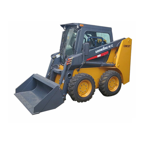
2.3 PURPOSE 2.3.1 CDM307, CDM308, CDM312 Skid Steer Loader are suitable for operating in small working sites, uneven ground, the places of job changed frequently, but also for large construction machinery and auxiliary equipment. They are Widely used in road maintenance, pipeline placing, cable placing, park virescence, snow shoveling, transportation , excavating and crushing.
-
Page 32: Machine Specification
CHAPTER III MACHINE OPERATION 2.4 MACHINE SPECIFICATION Figure 4 Figure 5 SCHMEMATIC OF MACHINE SPECIFICATIONS TECHNIC SPECIFICATIONS OF CDM307、CDM308、CDM312…
-
Page 33
CHAPTER III MACHINE OPERATION Table 4 Dimension Unit CDM307 CDM308 CDM312 Max. Operating height 3850 3850 3880 Bucket pin height 2920 3050 3060 Cab roof height 2020 2020 2050 Max. Height of horizontal 2730 2850 2870 bucket Length without attachments… -
Page 34: Hydraulic System
CHAPTER III MACHINE OPERATION 2.5 HYDRAULIC SYSTEM 2.5.1 IMPLEMENT HYDRAULIC SYSTEM 2.5.1.1 Implement hydraulic system is used to control the action of the bucket, including oil tanks, implement pump, the multiple way valve, the boom cylinder, the tilt cylinders, the leveling valve, oil tubes and other components.
-
Page 35
CHAPTER III MACHINE OPERATION Figure 6 HYDRAULIC SYSTEM DIAGRAM… -
Page 36
CHAPTER III MACHINE OPERATION 2.5.3 THE WORKING DEVICE 2.5.3.1 The working device of the loader is mainly made up of the lift arm, the bucket base and the bucket. See the Figure 7. Figure7 WORKING DEVICE 1. LIFT ARM 2. BUCKET SEAT 3. -
Page 37: Electrical System
CHAPTER III MACHINE OPERATION 2.5.4 THE FRAME 2.5.4.1 The frame is a installing and connecting base of all parts of the machine. The frame adopts a high strength welding technology to assures long-time work in intensive operating environment. Integration design of the fuel tank , the hydraulic oil tank and the machine body greatly improves the effective utilization ratio of the solvent and the space of the oil tank.
-
Page 38
CHAPTER III MACHINE OPERATION 2.6.3 BATTERT CHARGING Do charge the battery following the regulations. Please charge once every three months or start the engine once every other time, when the machine is parked for long time. Run the machine for some time to charge the battery fully. -
Page 39
CHAPTER III MACHINE OPERATION Figure 9 ELECTRICAL WIRING DIAGRAM… -
Page 40: Chapter Iii Machine Operation
CHAPTER III MACHINE OPERATION CHAPTER III MACHINE OPERATION…
-
Page 41: Control Machenism And Instrument
CHAPTER III MACHINE OPERATION 3.1 CONTROL MACHENISM AND INSTRUMENT 3.1.1 INSTRUMENT AND INDICATING LAMPS Instrument panel is on the right of the cab, the front of the cab. The operator can easily see the instrument lamps and indicating lamps.,meanwhile the operator has a clear and wide view. See the Figure 10.
-
Page 42: Operation Of Skid Steer Loader
CHAPTER III MACHINE OPERATION Figure 11 KEY SHIFT POSITION DIAGRAM OF ELECTRIC LOCK 3.2 OPERATION OF SKID STEER LOADER 3.2.1 PRECAUTION WHEN OPERATING 3.2.1.1 Diesel of skid steer loader should be pure and be deposited for at least 72 hours , diesel No.
-
Page 43
CHAPTER III MACHINE OPERATION the diesel engines maintenance instruction requested correct power adjusts its actual power, to ensure the proper use of Skid Steer Loader. 3.2.1.8 In order to improve the hot and cold regions loader operator comfort, equipped with air conditioner on request. -
Page 44
CHAPTER III MACHINE OPERATION 3.2.3 SEAT ADJUSTMENT INSTRUCTIONS Front -rear adjusting handle Figure13 ADJUSTMENT TO SEAT 1. Suitable weight adjustment: according to his weight, the user can turn the weight adjustment knob, turning the knob clockwise to increase the suitable weight, and turning knob counterclockwise to decrease the suitable weight. -
Page 45
CHAPTER III MACHINE OPERATION 3. Before using the safety belt, inspect whether the lock of the safety belt can function normally or not. 3.2.5 THE USE OF SECURITY ROD 3.2.5.1 Before engine starts, pull down the security bar, that is locked state. As shown in figure 14: Figure 14 SECURITY ROD 3.2.5.2 Security rod: Security bar is very important for operator, when a sudden stop during the… -
Page 46
CHAPTER III MACHINE OPERATION Figure 15 THE SECURITY ROD IS NEAR WITH THE SWITCH 3.2.6 MACHINE OPERATION 3.2.6.1 Left Control Handle: The left joystick controls the left driving system and the boom, its position and the corresponding functions are in the following table. Figure 16 LEFT HANDLE OPERATION… -
Page 47
CHAPTER III MACHINE OPERATION Direction Function Front Left wheel forward Rear Left wheel backward Left Boom upper Right Boom lower 3.2.6.2 The right control lever: the right joystick controls the right driving system and the bucket .its position and the corresponding functions are shown in the following table. Figure 17 RIGHT HANDLE OPERATION SCHEME Direction Function… -
Page 48
CHAPTER III MACHINE OPERATION 3.2.7 REAR WINDOW 3.2.7.1 Rear Window is used as the emergency exit. Once the accident caused the routine exit blocked, the operator can open the rear window as emergency exits as follows: Remove the rubber rectangle band, the end of rectangle band is near the top left corner in the rear window ( as shown Figure 17 );… -
Page 49
CHAPTER III MACHINE OPERATION 3.2.8 THROTTLE CONTROL There are the handle and the foot throttle controls, as shown Figure 19 Figure 19 THROTTLE CONTROL 1. FOOT THROTTLE 2. HANDLE THROTTLE 1. Handle throttle control Move the Handle throttle control forward to increase the engine speed, move backward to reduce the engine speed. -
Page 50
CHAPTER III MACHINE OPERATION 3.2.9 AUXILIARY HYDRAULIC CONTROL FOR THE ATTACHMENTS AND FOOT THROTTLE DEVICE As shown. Figure 20 AUXILIARY HYDRAULIC CONTROL FOR THE ATTACHMENTS AND FOOT THROTTLE DEVICE 3.2.9.1 Auxiliary hydraulic control: the pedal controls the hydraulic flow direction for the front attatchments (hydraulic quick dis-connect joint on the left arm), step the pedal on the left or right side depending on the hydraulic flow direction required. -
Page 51: The Main Technic Data Of Common Use
CHAPTER III MACHINE OPERATION 3.3 THE MAIN TECHNIC DATA OF COMMON USE 3.3.1 ENGINE 3.3.1.1 Cooling water temperature ( ℃ . S uitable inlet water temperature 45 ~ 60 S uitable outlet water temperature 60 ~ 90 .…
-
Page 52: Insection Before Operation
) Glycerol 66.7%, water 33.3%( weight ratio ) 3.4.2.1 To ensure the engine cooling system work in different working conditions, under different circumstances, recommended to use Lonking dedicated coolant 3.5 INSECTION BEFORE OPERATION 3.5.1 ENGINE AND INSTRUMENT SENCTION 3.5.1.1 Check the tank water level.
-
Page 53
CHAPTER III MACHINE OPERATION 3.5.2 CHASSIS SENCTION 3.5.2.1 Check the amount of hydraulic oil. 3.5.2.2 Check the hydraulic system piping and accessories of seal. 3.5.2.3 Check the flexibility of the joystick and whether on Neutral position. 3.5.2.4 Check the tire pressure is normal. 3.5.3 STARTING THE ENGINE 3.5.3.1 Check the meter indication is normal. -
Page 54: Starting And Parking
CHAPTER III MACHINE OPERATION Table 7 Ambient temperature Preheating time Above 10 ℃ ( ° ) No need About 5S ℃ ( ° ) - ℃ ( ° ) Below About 10S - ℃ ( ° ) Limit for continuous use When the preheating light is off, turn the electric key to the «start»…
-
Page 55: Operation Control
CHAPTER III MACHINE OPERATION 3.6.1.3 Please adjust, fix and lock the seat, fasten seat belts before starting the machine. 3.6.1.4 Put down the safety lever. only when lowering the safety lever, the machine could start. 3.6.1.5 warm up the machine at an idle speed after the machine starts. Until water outlet temperature of the diesel reaches 55 and the engine oil temperature reaches 45 , do not operate the…
-
Page 56
CHAPTER III MACHINE OPERATION… -
Page 57
CHAPTER III MACHINE OPERATION Figure 21 SHOVEL EARTH 、 T aking back and lifting the bucket. 、 K eep the bucket 300mm from the ground during the transportation.(as shown in the figure 22) Figure 22 TRANSPORTATION 、 A rrived at the designated location, rising boom, dumping, all operations are stable. -
Page 58
CHAPTER III MACHINE OPERATION Warning: The cutting edge and teeth of bucket may run into frozen or buried objects such as rocks while shoveling. Check and mark before the operation, keep the bucket flat with the ground, avoiding obstacles, and also not too fast. 3.7.2.2 Operating on the hillside or slope Warning: Operating on the hillside is more dangerous, and should pay attention to the ground… -
Page 59
CHAPTER III MACHINE OPERATION Figure 24 DOWNGRADE WITH FULL LOAD 3.7.2.4 When the bucket is empty 1. If the bucket is empty, should be positive downgrading the slope and reverse upgrading the slope.(as shown in the figure 25,26) Figure 25 UPGRADE WITH BUCKET EMPTY… -
Page 60
CHAPTER III MACHINE OPERATION Figure 26 DOWNGRADE WITH BUCKET EMPTY… -
Page 61: Chapter Iv Maintenance Section
CHAPTER IV MAINTENANCE SECTION CHAPTER IV MAINTENANCE SECTION…
-
Page 62: Maintenance And Precautions Of Skid Loader
CHAPTER IV MAINTENANCE SECTION 4.1 MAINTENANCE AND PRECAUTIONS OF SKID LOADER. 4.1.1 THE USER SHALL CARRY OUT RUNNING-IN LF NEW LOADER AFTER PURCHASING THE LOADER, IN THE COURSE OF RUNNING-IN OF NEW LOADER. OPERATION AND MAINTENANCE IN ACCORDANCE WITH THE FOLLOWING REGULATION. PRECAUTIONS IN THE COURSE OF RUNNING-IN: 4.1.1.1 The running-in period for a new loader is 100 hours, the forward gear 2 and reverse gear 2 shall be arranged for running-in respectively.
-
Page 63
As a result, select the special or appointed oil liquid products of lonking. 4.1.6.5 Please ensure the purity of the oil liquid, the damage of the machine caused by the unqualified oil will not be covered by our warranty. -
Page 64: Maintenance Of Main Components
. Y ou can get lonking special or designated oil, liquid products and original parts and components from Lonking spare parts company or commission business in various places conveniently. 4.2 MAINTENANCE OF MAIN COMPONENTS 4.2.1 PRECAUTIONS OF DIESEL ENGINE MAINTENANCE…
-
Page 65
CHAPTER IV MAINTENANCE SECTION draining time of large current is too long which lead to the damage of pole plate of battery inside. 4.3.2 MAINTENANCE OF ACCUMULATOR OF MACHINE IN STOCK 4.3.2.1 Charging enough before the battery in stock for a long time, cut off cathode clamp of battery in stock to release the drain power. -
Page 66: Lubrication
CHAPTER IV MAINTENANCE SECTION 4.3.5.3 Gas will be produced in the process of charging, inspect whether the venthole on both sides of the top cover of battery is draughty or not. Make sure the venthole draughty to prevent the battery explode. 4.3.5.4 No charging battery whose outside case is misshapen as a result of overcharging or its electrolyte dry.
-
Page 67
CHAPTER IV MAINTENANCE SECTION TABLE 8 Adding oil quantity(litre) Type Name Application parts Note (reference value) Details see to manual of the diesel engine(CF5W/40 suitable for Diesel oil CF15W/40 ≥20 Diesel winter in the north or exported to the cold area) Low temperature and pressure Lubricating 2# universal lithium… -
Page 68
CHAPTER IV MAINTENANCE SECTION 4.4.1.7 Regular maintenance should be done in daily , 50,100, 250, 500, 1000, 2000 hours. TABLE 9 cycle Inspect content I nspect the level of the cooling water and the anti-freezing fluid . . I nspect oil sump of the diesel, engine oil surface of the speed regulator(injection pump) .… -
Page 69
CHAPTER IV MAINTENANCE SECTION . I nspect the oil level in the oil tank of the chain wheel. C lean the cooler. . . I nspect whether the fan leather belt is normal or not. I nspect the tightness torque of the hydraulic motor and the nuts for the .… -
Page 70: Chapter V Hoisting And Transportation Securing Of Skid Steer Loader
CHAPTER V HOISTINGAND TRANSPORTATION SECUTING CHAPTER V HOISTING AND TRANSPORTATION SECURING OF SKID STEER LOADER…
-
Page 71: Hoisting And Transportation Of Skid Loader
CHAPTER V HOISTINGAND TRANSPORTATION SECUTING 5.1 HOISTING AND TRANSPORTATION OF SKID LOADER 5.1.1 When loader needs hoisting, the lifting hook can be used to catch the ear-plate available on the machine body. Before hoisting, adjust the length of ropes to keep the level of the machine. When hoisting, keep the lifting hook stable, better with the special tools lest steel ropes hit the machine hood and the cab.
-
Page 72
CHAPTER V HOISTINGAND TRANSPORTATION SECUTING smoothly. Make sure there is enough bearing capacity for the trailer, the truck and the handling platform to support the machine. Check whether there are some oil contaminants , ice blocks on the trailer, the truck and the handling platform. Clean them in time. -
Page 73
CHAPTER V HOISTINGAND TRANSPORTATION SECUTING the key. 2. Place wood wedges under every front and rear wheel. 3. Bind the front and rear shackles of the machine with the rope. 4. Record the height of the skid steer loader and the truck/trailer. Write down and stick inside the cab of the truck, so that decide the traffic ability of the truck correctly when travelling through the tunnel or meeting the high cable. -
Page 74: Chapter Vi Common Faults And Trouble-Shooting
CHAPTER VI COMMON FAULTS AND TROUBLESHOOTING CHAPTER VI COMMON FAULTS AND TROUBLE-SHOOTING…
-
Page 75: Common Trouble-Shooting
CHAPTER VI COMMON FAULTS AND TROUBLESHOOTING 6.1 COMMON TROUBLE-SHOOTING 6.1.1 DURING THE OPERATION, SOME TROUBE-SHOUTING ARE AS THE FOLLOWING TABLE.(TABLE 10) TABLE 10 Fault Characteristics Fault causes Trouble-shooting Electrical System When the engine is running, even if at an Alternator fault Replace high speed,…
-
Page 76
CHAPTER VI COMMON FAULTS AND TROUBLESHOOTING pressure alarm Oil level is too low Fuel Oil filter plug Replace filter lamp light still when suitable Replace the engine run at the surroundings high speed. Coolant level is too low Fill the coolant. Radiator leaks Repair Fan belt is loosing… -
Page 77
CHAPTER VI COMMON FAULTS AND TROUBLESHOOTING obstructed Traveling motor fault Repair or replace The brake light is always Inspect the seat switch and safety rod switch. Oil level is too low Fuel There is spume. Use pulsive oil Oil suction pipe is too Inspect and remove leak Machine moves… -
Page 78: Reasons For Accumulator Losing Power
CHAPTER VI COMMON FAULTS AND TROUBLESHOOTING The power of engine is Inspect whether fuel filter, machine reduced. injector pump and valve plug or accelerate slowly. The setting of releasing pressure is incorrect. Adjust to rated value Seal ring is damaged. Replace The pressure of pump Discharging is plugged or…
-
Page 79: Battery Charging
CHAPTER VI COMMON FAULTS AND TROUBLESHOOTING 6.3.2 The accumulator with the end pillar broke can not be supplied, find the causes and then replace. 6.3.3 Accumulator with the white electrical eyes, make sure that whether caused by the jam of the green ball inside the electrical eye or not, if that , could shake the ball lightly.
-
Page 80: Appendix: Reference Table Of Density Of Common Materials
APPENDIX REFERENCE TABLE OF DENSITY OF COMMON MATERIALS APPENDIX: REFERENCE TABLE OF DENSITY OF COMMON MATERIALS Material Specific Reference to the value of Notes name Categories Kg/m 1 2 5 0 Stick thin dry soil 1 5 2 0 Caking dry soil 1 5 5 0 Powder dry soil Ordinary soil…
-
Page 81
APPENDIX REFERENCE TABLE OF DENSITY OF COMMON MATERIALS 1 5 5 0 Fragmentation Limestone 2 6 0 0 A solid block 1 7 6 0 — 2 1 0 0 Slag 1 6 5 0 Chunky Granite 2 8 0 0 Overall 2 4 6 0 Hematite…
File Specifications:1562/1562792-cdm307.pdf file (16 May 2023) |
Accompanying Data:
Lonking CDM307 Mini Skid Steers PDF Operation Manual (Updated: Tuesday 16th of May 2023 05:18:13 PM)
Rating: 4.1 (rated by 9 users)
Compatible devices: DMR108, LS160, Ditch Witch SK350, TA9, SK650, SK750, CARRY 110, AP-SH35.
Recommended Documentation:
Operation Manual (Text Version):
(Ocr-Read Summary of Contents of some pages of the Lonking CDM307 Document (Main Content), UPD: 16 May 2023)
-
22, CHAPTER SAFETY INFORMATION 16 cause serious personal injury. If the liquid injected into your skin, it must be treated immediately. Please seek treatment from a doctor that is familiar with this type of injury. 1.5.7 PRESSURIZED AIR AND FLUIDS 1.5.7.1 Compressed air or water pressure or hot water may cause debris or hot water to be blown out. This would cause person injury. 1.5.7.2 When pressurized air or water is used for cleaning, wear protective clothing, protective shoes a…
-
50, CHAPTER III MACHINE OPERATION 44 3.2.9 AUXILIARY HYDRAULIC CONTROL FOR THE ATTACHMENTS AND FOOT THROTTLE DEVICE As shown. Figure 20 AUXILIARY HYDRAULIC CONTROL FOR THE ATTACHMENTS AND FOOT THROTTLE DEVICE 3.2.9.1 Auxiliary hydraulic control: the pedal controls the hydraulic flow direction for the front attatchments (hydraulic quick dis-connect joint on the left arm), step the pedal on the left or right side depending on the h…
-
18, Lonking CDM307 CHAPTER SAFETY INFORMATION 12 LABEL OF HYDRAULIC OIL (16) Label location: inside the hydraulic oil tank on the frame Fill the tank with clean hydraulic oil in time to avoid engine stopping working. Filling wrong oil may make the machine disable and damage the machine. Figure 4 16 WARNING LABEL FOR THE RADIATOR AND THE FAN (17) Label location: it is on the radiator. In order to avoid body injuries, do not touch the radiator when the machine is warming up. Do not keep close to the fan when the…
-
Lonking CDM307 User Manual
-
Lonking CDM307 User Guide
-
Lonking CDM307 PDF Manual
-
Lonking CDM307 Owner’s Manuals
Recommended: U22, NS-C2000 — AM/FM Clock Radio, K — 285, DJ-150E
Links & Tools
Operating Impressions, Questions and Answers:
CONTENT
4.4 LUBRICATION…………………………………………………………………………………………………………………….. 59
CHAPTER V HOISTING AND TRANSPORTATION SECURING OF SKID STEER LOADER…………. 63
5.1 HOISTING AND TRANSPORTATION OF SKID LOADER…………………………………………………… 64
CHAPTER VI COMMON FAULTS AND TROUBLE-SHOOTING……………………………………………………… 67
6.1 COMMON TROUBLE-SHOOTING……………………………………………………………………………………… 68
6.2 REASONS FOR ACCUMULATOR LOSING POWER ………………………………………………………… 71
6.3 PRECATIONS BEFORE CHARGING THE ACCUMULATOR……………………………………………… 71
6.4 BATTERY CHARGING………………………………………………………………………………………………………… 72
APPENDIX: REFERENCE TABLE OF DENSITY OF COMMON MATERIALS……………………………….. 73
2
Table of Contents for Lonking CDM307:
-
PREFACE PREFACE Manual Information Please keep the Manual book safely in the cab for consult momentarily. Read and understand the content before use the machine. It may not include the improve and update parts of the product. Some structures or accessories in the photos or pictures of this manual may be different from your machine. If you have any questions about the book, please contact Lonking China agents for lately information. Structur
-
CHAPTER III MACHINE OPERATION 36 Figure 11 KEY SHIFT POSITION DIAGRAM OF ELECTRIC LOCK 3.2 OPERATION OF SKID STEER LOADER 3.2.1 PRECAUTION WHEN OPERATING 3.2.1.1 Diesel of skid steer loader should be pure and be deposited for at least 72 hours , diesel No. should meet the stated quality requirements. 3.2.1.2 A regular maintenance and lubrication foe skid steer loader should be performed following the regulatio
Questions, Opinions and Exploitation Impressions:
You can ask a question, express your opinion or share our experience of Lonking CDM307 device using right now.
- Manuals
- Brands
- Lonking Manuals
- Mini Skid Steers
- CDM307
- Operation manual
-
Contents
-
Table of Contents
-
Bookmarks
Quick Links
CDM307
CDM308 Operation Manual
CDM312
Summary of Contents for Lonking CDM307
-
Page 1
CDM307 CDM308 Operation Manual CDM312… -
Page 3: Dear User
Thank you for selecting LONKING skid steer loader! This Operation Manual briefly introduces the safety and maintenance regulations of CDM308 ( include CDM307 and CDM312 ) skid steer loader for the use and reference of machine operators, maintainers and technical managers.
-
Page 4: Preface
Some structures or accessories in the photos or pictures of this manual may be different from your machine. If you have any questions about the book, please contact Lonking China agents for lately information. Structure The manual include six parts, preface, safety information, machine information, machine operation, maintenance part, hoisting and transportation of skid steer loader, common faults and troubleshooting, reference tables of density of common materials.
-
Page 5: Table Of Contents
CONTENT CONTENT DEAR USER…………………………..1 PREFACE…………………………… 1 CHAPTER I SAFETY INFORMATION………………….1 1.1 SAFETY PROMPT……………………..2 1.2 SAFETY LABEL……………………….. 2 1.3 UNDERSTAND THE MEANING OF THE SAFETY SYMBOL…………3 1.4 DISTRIBUTING SCHEMATIC OF SAFETY AND ADDITIVE LABELS………. 4 1.5 OTHER SAFETY INFORMATION………………… 14 CHAPTER II PRODUCT INFORMATION…………………..
-
Page 6
CONTENT 4.4 LUBRICATION……………………….59 CHAPTER V HOISTING AND TRANSPORTATION SECURING OF SKID STEER LOADER….. 63 5.1 HOISTING AND TRANSPORTATION OF SKID LOADER…………64 CHAPTER VI COMMON FAULTS AND TROUBLE-SHOOTING…………… 67 6.1 COMMON TROUBLE-SHOOTING………………..68 6.2 REASONS FOR ACCUMULATOR LOSING POWER …………..71 6.3 PRECATIONS BEFORE CHARGING THE ACCUMULATOR………… -
Page 7: Chapter I Safety Information
CHAPTER Ⅰ SAFETY INFORMATION CHAPTER I SAFETY INFORMATION Please read and understand all the precautions of above Safety mask in the manual or on the machine, and strictly observe these safety precautions during operation or repair.
-
Page 8: Safety Prompt
1.2.6 Replace any damaged and lost safety labels. 1.2.7 If any part sticking safety label is need of replacement, new safety label need to stick in the changed part. 1.2.8 Various new safety labels are provided in any Lonking after-service institution.
-
Page 9: Understand The Meaning Of The Safety Symbol
CHAPTER Ⅰ SAFETY INFORMATION 1.3 UNDERSTAND THE MEANING OF THE SAFETY SYMBOL 1.3.1 In the safety labels on the machine, words indicating degree or level of hazards — DANGER ( ) , WARNING ( ) or CAUTION ( ) — and use with the label of being careful. 危…
-
Page 10: Distributing Schematic Of Safety And Additive Labels
CHAPTER Ⅰ SAFETY INFORMATION 1.4 DISTRIBUTING SCHEMATIC OF SAFETY AND ADDITIVE LABELS FIGURE 4 DISTRIBUTING SCHEMATIC DIAGRAM OF SAFETY LABELS AND ADDITIVE LABELS…
-
Page 11
CHAPTER Ⅰ SAFETY INFORMATION WARNING LABEL OF TIPPING HAZARD (1) Label location: right inside the lift arm The loading weight must be within the range of rated load, not out of the range, otherwise the machine may overturn. It may damage the machine and cause serious casualties. -
Page 12
CHAPTER Ⅰ SAFETY INFORMATION WARNING LABEL FOR OPENING LOCKED PIN (3) Label location: inside the cab Make sure operate the machine strictly according to the warning label, or damages of machine may occur. Figure 4 — — — — 3 CRUSHING DANGER LABEL (4) Label location: inside the cab Make sure to operate the machine strictly… -
Page 13
CHAPTER Ⅰ SAFETY INFORMATION RIGHT CONTROL HANDLE FUNCTION LABEL (5) Label location: inside the right control handle hood Inform the user that the right control handle controls the right travel of the machine, tilting back and dumping of the bucket. Figure 4 — — — — 5 LEFT CONTROL HANDLE FUNCTION LABEL (6) Label location: inside the right control handle hood… -
Page 14
CHAPTER Ⅰ SAFETY INFORMATION SAFETY BRACING WARNING LABEL (7) Label location: outside of the safety bar, on the right of the lift arm When the lift arm is lifting for checking, put down the securing bar. Otherwise, personnel casualties may happen.. 图… -
Page 15
CHAPTER Ⅰ SAFETY INFORMATION PINCHING HANDS WARNING LABEL (10) Label location: on the right rear side of the frame when the lift arm is down. Never put your body here to avoid crushing injuries or casualties. Figure 4 — — — — 1 0 START-UP HAZARDS LABEL OF THE ENGINE (11) Label location: where the engine starts Make sure operate the machine strictly… -
Page 16
CHAPTER SAFETY INFORMATION Ⅰ MAINTENANCE AND LUBRICATION LABEL (12) Label location: on the left rear side of the frame Make sure maintain lubricate the machine according to the label. Otherwise, the machine damage may be caused. Figure 4 — — — — 1 2 HOIST LABEL (13) Label location: at both rear-upper sides of the frame , and both front sides of the frame. -
Page 17
CHAPTER Ⅰ SAFETY INFORMATION NO USE OF AETHER HAZARD (14) Label location: at both rear-upper sides of the frame , both front sides of the frame. Make sure to operate the machine strictly according to the warning label, or it may cause machine damage or serious personnal casualties. -
Page 18
CHAPTER Ⅰ SAFETY INFORMATION LABEL OF HYDRAULIC OIL (16) Label location: inside the hydraulic oil tank on the frame Fill the tank with clean hydraulic oil in time to avoid engine stopping working. Filling wrong oil may make the machine disable and damage the machine. -
Page 19
CHAPTER Ⅰ SAFETY INFORMATION (18) WARNING LABEL FOR BINDING POSITION Label location: it is in front of the frame, rear side of the balancing weight. Inform users that where the binding position is in the transportation, to bind this hook in order to secure the machine in the transporting vehicle. -
Page 20: Other Safety Information
CHAPTER Ⅰ SAFETY INFORMATION 1.5 OTHER SAFETY INFORMATION 1.5.1 OBSERVE SAFETY INDICATION 1.5.1.1 Before the maintenance and repair , hanging a warning signs on the start switch or control handle, such as «No action»or other similar warning signs. 1.5.1.2 Know the working width of the machine. When the machine works in the neighbourhood of the fence or the border barriers, personnels can keep distance of the machine.
-
Page 21
CHAPTER Ⅰ SAFETY INFORMATION avoid the economic loss or personal injury. 1.5.3.2 Check whether all the instruments are be operated normally or not. nonshorted terminal post of start motor or battery. Short circuit makes the circuit round the normal starting system of engine. Short circuit system can also cause damage to the circuit system. -
Page 22
CHAPTER Ⅰ SAFETY INFORMATION cause serious personal injury. If the liquid injected into your skin, it must be treated immediately. Please seek treatment from a doctor that is familiar with this type of injury. 1.5.7 PRESSURIZED AIR AND FLUIDS 1.5.7.1 Compressed air or water pressure or hot water may cause debris or hot water to be blown out. -
Page 23
1.5.10.2 Please repair any lines that are loosen or damaged. Leaks may provide fuel for fires. Consult your Lonking dealer for repair or for replacement parts. 1.5.10.3 Perform a double check to lines. Do not use bare hands to check for leak. Please Use board or cardboard to check for leak. -
Page 24
CHAPTER Ⅰ SAFETY INFORMATION 1.5.11 TIRE IFORMATION 1.5.11.1 Explosion of air inflated tires have resulted from heat-induced gas combusion inside the tires. explosion can be caused by heat that is generated by welding ,by heating rim components, by external fire. 1.5.11.2 A tire explosion is much more violent than a blowout. -
Page 25
CHAPTER Ⅰ SAFETY INFORMATION Note: The three-point contact can be both hands and a foot or both feet and a hand. 1.5.14.3 Do not mount the moving machine. Prohibit getting down from the moving machine. Do not jump down from the machine. When get up and down machine, do not carry tools or objects. Use hand-pulled rope to pull the equipment to the platform. -
Page 26
CHAPTER Ⅰ SAFETY INFORMATION 1.5.16.11 Before adjusting the machine, make sure that no person is between the machine and the equipments. Pave the hook of the traction device to align the traction equipment with the traction pin. Adjust the machine. Connect the machine to the towing equipment. You should know the maximum size of your machine. -
Page 27
CHAPTER Ⅰ SAFETY INFORMATION . O perating on the slope will affect the normal performance of the machine, promote the instability of the machine and increase more hazards. 1.5.20 CNETAINING FLUID SPILLAGE 1.5.20.1 Be careful so as to ensure that fluids are contained during performane of inspection, maintenance, testing , adjusting and repair of the equipment. -
Page 28: Chapter Ii Product Information
CHAPTER III MACHINE OPERATION CHAPTER II PRODUCT INFORMATION…
-
Page 29: Machine Qualification
2.1 MACHINE QUALIFICATION 2.1.1 Labels are mounted on every machine to manage every machine produced by the LONKING Holdings Limited. They are at the different position of the machine. Here are description about the plates below. 2.1.2 APPRAISAL MARK AND THE IDENTIFICATION NUMBER OF THE MACHINE The appraisal mark sees the front position of the machine.
-
Page 30
CHAPTER III MACHINE OPERATION . C DM308 adopts Kubota V3600 engine The following table lists the basic parameters of Kubota V3600 engine Table 2 Project Parameter Cylinder number-Inner diameter ( ) ×distance - 9 8mm × 1 20mm Seted power r otate speed r pm 50kW… -
Page 31: Purpose
2.3 PURPOSE 2.3.1 CDM307, CDM308, CDM312 Skid Steer Loader are suitable for operating in small working sites, uneven ground, the places of job changed frequently, but also for large construction machinery and auxiliary equipment. They are Widely used in road maintenance, pipeline placing, cable placing, park virescence, snow shoveling, transportation , excavating and crushing.
-
Page 32: Machine Specification
CHAPTER III MACHINE OPERATION 2.4 MACHINE SPECIFICATION Figure 4 Figure 5 SCHMEMATIC OF MACHINE SPECIFICATIONS TECHNIC SPECIFICATIONS OF CDM307、CDM308、CDM312…
-
Page 33
CHAPTER III MACHINE OPERATION Table 4 Dimension Unit CDM307 CDM308 CDM312 Max. Operating height 3850 3850 3880 Bucket pin height 2920 3050 3060 Cab roof height 2020 2020 2050 Max. Height of horizontal 2730 2850 2870 bucket Length without attachments… -
Page 34: Hydraulic System
CHAPTER III MACHINE OPERATION 2.5 HYDRAULIC SYSTEM 2.5.1 IMPLEMENT HYDRAULIC SYSTEM 2.5.1.1 Implement hydraulic system is used to control the action of the bucket, including oil tanks, implement pump, the multiple way valve, the boom cylinder, the tilt cylinders, the leveling valve, oil tubes and other components.
-
Page 35
CHAPTER III MACHINE OPERATION Figure 6 HYDRAULIC SYSTEM DIAGRAM… -
Page 36
CHAPTER III MACHINE OPERATION 2.5.3 THE WORKING DEVICE 2.5.3.1 The working device of the loader is mainly made up of the lift arm, the bucket base and the bucket. See the Figure 7. Figure7 WORKING DEVICE 1. LIFT ARM 2. BUCKET SEAT 3. -
Page 37: Electrical System
CHAPTER III MACHINE OPERATION 2.5.4 THE FRAME 2.5.4.1 The frame is a installing and connecting base of all parts of the machine. The frame adopts a high strength welding technology to assures long-time work in intensive operating environment. Integration design of the fuel tank , the hydraulic oil tank and the machine body greatly improves the effective utilization ratio of the solvent and the space of the oil tank.
-
Page 38
CHAPTER III MACHINE OPERATION 2.6.3 BATTERT CHARGING Do charge the battery following the regulations. Please charge once every three months or start the engine once every other time, when the machine is parked for long time. Run the machine for some time to charge the battery fully. -
Page 39
CHAPTER III MACHINE OPERATION Figure 9 ELECTRICAL WIRING DIAGRAM… -
Page 40: Chapter Iii Machine Operation
CHAPTER III MACHINE OPERATION CHAPTER III MACHINE OPERATION…
-
Page 41: Control Machenism And Instrument
CHAPTER III MACHINE OPERATION 3.1 CONTROL MACHENISM AND INSTRUMENT 3.1.1 INSTRUMENT AND INDICATING LAMPS Instrument panel is on the right of the cab, the front of the cab. The operator can easily see the instrument lamps and indicating lamps.,meanwhile the operator has a clear and wide view. See the Figure 10.
-
Page 42: Operation Of Skid Steer Loader
CHAPTER III MACHINE OPERATION Figure 11 KEY SHIFT POSITION DIAGRAM OF ELECTRIC LOCK 3.2 OPERATION OF SKID STEER LOADER 3.2.1 PRECAUTION WHEN OPERATING 3.2.1.1 Diesel of skid steer loader should be pure and be deposited for at least 72 hours , diesel No.
-
Page 43
CHAPTER III MACHINE OPERATION the diesel engines maintenance instruction requested correct power adjusts its actual power, to ensure the proper use of Skid Steer Loader. 3.2.1.8 In order to improve the hot and cold regions loader operator comfort, equipped with air conditioner on request. -
Page 44
CHAPTER III MACHINE OPERATION 3.2.3 SEAT ADJUSTMENT INSTRUCTIONS Front -rear adjusting handle Figure13 ADJUSTMENT TO SEAT 1. Suitable weight adjustment: according to his weight, the user can turn the weight adjustment knob, turning the knob clockwise to increase the suitable weight, and turning knob counterclockwise to decrease the suitable weight. -
Page 45
CHAPTER III MACHINE OPERATION 3. Before using the safety belt, inspect whether the lock of the safety belt can function normally or not. 3.2.5 THE USE OF SECURITY ROD 3.2.5.1 Before engine starts, pull down the security bar, that is locked state. As shown in figure 14: Figure 14 SECURITY ROD 3.2.5.2 Security rod: Security bar is very important for operator, when a sudden stop during the… -
Page 46
CHAPTER III MACHINE OPERATION Figure 15 THE SECURITY ROD IS NEAR WITH THE SWITCH 3.2.6 MACHINE OPERATION 3.2.6.1 Left Control Handle: The left joystick controls the left driving system and the boom, its position and the corresponding functions are in the following table. Figure 16 LEFT HANDLE OPERATION… -
Page 47
CHAPTER III MACHINE OPERATION Direction Function Front Left wheel forward Rear Left wheel backward Left Boom upper Right Boom lower 3.2.6.2 The right control lever: the right joystick controls the right driving system and the bucket .its position and the corresponding functions are shown in the following table. Figure 17 RIGHT HANDLE OPERATION SCHEME Direction Function… -
Page 48
CHAPTER III MACHINE OPERATION 3.2.7 REAR WINDOW 3.2.7.1 Rear Window is used as the emergency exit. Once the accident caused the routine exit blocked, the operator can open the rear window as emergency exits as follows: Remove the rubber rectangle band, the end of rectangle band is near the top left corner in the rear window ( as shown Figure 17 );… -
Page 49
CHAPTER III MACHINE OPERATION 3.2.8 THROTTLE CONTROL There are the handle and the foot throttle controls, as shown Figure 19 Figure 19 THROTTLE CONTROL 1. FOOT THROTTLE 2. HANDLE THROTTLE 1. Handle throttle control Move the Handle throttle control forward to increase the engine speed, move backward to reduce the engine speed. -
Page 50
CHAPTER III MACHINE OPERATION 3.2.9 AUXILIARY HYDRAULIC CONTROL FOR THE ATTACHMENTS AND FOOT THROTTLE DEVICE As shown. Figure 20 AUXILIARY HYDRAULIC CONTROL FOR THE ATTACHMENTS AND FOOT THROTTLE DEVICE 3.2.9.1 Auxiliary hydraulic control: the pedal controls the hydraulic flow direction for the front attatchments (hydraulic quick dis-connect joint on the left arm), step the pedal on the left or right side depending on the hydraulic flow direction required. -
Page 51: The Main Technic Data Of Common Use
CHAPTER III MACHINE OPERATION 3.3 THE MAIN TECHNIC DATA OF COMMON USE 3.3.1 ENGINE 3.3.1.1 Cooling water temperature ( ℃ . S uitable inlet water temperature 45 ~ 60 S uitable outlet water temperature 60 ~ 90 .…
-
Page 52: Insection Before Operation
) Glycerol 66.7%, water 33.3%( weight ratio ) 3.4.2.1 To ensure the engine cooling system work in different working conditions, under different circumstances, recommended to use Lonking dedicated coolant 3.5 INSECTION BEFORE OPERATION 3.5.1 ENGINE AND INSTRUMENT SENCTION 3.5.1.1 Check the tank water level.
-
Page 53
CHAPTER III MACHINE OPERATION 3.5.2 CHASSIS SENCTION 3.5.2.1 Check the amount of hydraulic oil. 3.5.2.2 Check the hydraulic system piping and accessories of seal. 3.5.2.3 Check the flexibility of the joystick and whether on Neutral position. 3.5.2.4 Check the tire pressure is normal. 3.5.3 STARTING THE ENGINE 3.5.3.1 Check the meter indication is normal. -
Page 54: Starting And Parking
CHAPTER III MACHINE OPERATION Table 7 Ambient temperature Preheating time Above 10 ℃ ( ° ) No need About 5S ℃ ( ° ) - ℃ ( ° ) Below About 10S - ℃ ( ° ) Limit for continuous use When the preheating light is off, turn the electric key to the «start»…
-
Page 55: Operation Control
CHAPTER III MACHINE OPERATION 3.6.1.3 Please adjust, fix and lock the seat, fasten seat belts before starting the machine. 3.6.1.4 Put down the safety lever. only when lowering the safety lever, the machine could start. 3.6.1.5 warm up the machine at an idle speed after the machine starts. Until water outlet temperature of the diesel reaches 55 and the engine oil temperature reaches 45 , do not operate the…
-
Page 56
CHAPTER III MACHINE OPERATION… -
Page 57
CHAPTER III MACHINE OPERATION Figure 21 SHOVEL EARTH 、 T aking back and lifting the bucket. 、 K eep the bucket 300mm from the ground during the transportation.(as shown in the figure 22) Figure 22 TRANSPORTATION 、 A rrived at the designated location, rising boom, dumping, all operations are stable. -
Page 58
CHAPTER III MACHINE OPERATION Warning: The cutting edge and teeth of bucket may run into frozen or buried objects such as rocks while shoveling. Check and mark before the operation, keep the bucket flat with the ground, avoiding obstacles, and also not too fast. 3.7.2.2 Operating on the hillside or slope Warning: Operating on the hillside is more dangerous, and should pay attention to the ground… -
Page 59
CHAPTER III MACHINE OPERATION Figure 24 DOWNGRADE WITH FULL LOAD 3.7.2.4 When the bucket is empty 1. If the bucket is empty, should be positive downgrading the slope and reverse upgrading the slope.(as shown in the figure 25,26) Figure 25 UPGRADE WITH BUCKET EMPTY… -
Page 60
CHAPTER III MACHINE OPERATION Figure 26 DOWNGRADE WITH BUCKET EMPTY… -
Page 61: Chapter Iv Maintenance Section
CHAPTER IV MAINTENANCE SECTION CHAPTER IV MAINTENANCE SECTION…
-
Page 62: Maintenance And Precautions Of Skid Loader
CHAPTER IV MAINTENANCE SECTION 4.1 MAINTENANCE AND PRECAUTIONS OF SKID LOADER. 4.1.1 THE USER SHALL CARRY OUT RUNNING-IN LF NEW LOADER AFTER PURCHASING THE LOADER, IN THE COURSE OF RUNNING-IN OF NEW LOADER. OPERATION AND MAINTENANCE IN ACCORDANCE WITH THE FOLLOWING REGULATION. PRECAUTIONS IN THE COURSE OF RUNNING-IN: 4.1.1.1 The running-in period for a new loader is 100 hours, the forward gear 2 and reverse gear 2 shall be arranged for running-in respectively.
-
Page 63
As a result, select the special or appointed oil liquid products of lonking. 4.1.6.5 Please ensure the purity of the oil liquid, the damage of the machine caused by the unqualified oil will not be covered by our warranty. -
Page 64: Maintenance Of Main Components
. Y ou can get lonking special or designated oil, liquid products and original parts and components from Lonking spare parts company or commission business in various places conveniently. 4.2 MAINTENANCE OF MAIN COMPONENTS 4.2.1 PRECAUTIONS OF DIESEL ENGINE MAINTENANCE…
-
Page 65
CHAPTER IV MAINTENANCE SECTION draining time of large current is too long which lead to the damage of pole plate of battery inside. 4.3.2 MAINTENANCE OF ACCUMULATOR OF MACHINE IN STOCK 4.3.2.1 Charging enough before the battery in stock for a long time, cut off cathode clamp of battery in stock to release the drain power. -
Page 66: Lubrication
CHAPTER IV MAINTENANCE SECTION 4.3.5.3 Gas will be produced in the process of charging, inspect whether the venthole on both sides of the top cover of battery is draughty or not. Make sure the venthole draughty to prevent the battery explode. 4.3.5.4 No charging battery whose outside case is misshapen as a result of overcharging or its electrolyte dry.
-
Page 67
CHAPTER IV MAINTENANCE SECTION TABLE 8 Adding oil quantity(litre) Type Name Application parts Note (reference value) Details see to manual of the diesel engine(CF5W/40 suitable for Diesel oil CF15W/40 ≥20 Diesel winter in the north or exported to the cold area) Low temperature and pressure Lubricating 2# universal lithium… -
Page 68
CHAPTER IV MAINTENANCE SECTION 4.4.1.7 Regular maintenance should be done in daily , 50,100, 250, 500, 1000, 2000 hours. TABLE 9 cycle Inspect content I nspect the level of the cooling water and the anti-freezing fluid . . I nspect oil sump of the diesel, engine oil surface of the speed regulator(injection pump) .… -
Page 69
CHAPTER IV MAINTENANCE SECTION . I nspect the oil level in the oil tank of the chain wheel. C lean the cooler. . . I nspect whether the fan leather belt is normal or not. I nspect the tightness torque of the hydraulic motor and the nuts for the .… -
Page 70: Chapter V Hoisting And Transportation Securing Of Skid Steer Loader
CHAPTER V HOISTINGAND TRANSPORTATION SECUTING CHAPTER V HOISTING AND TRANSPORTATION SECURING OF SKID STEER LOADER…
-
Page 71: Hoisting And Transportation Of Skid Loader
CHAPTER V HOISTINGAND TRANSPORTATION SECUTING 5.1 HOISTING AND TRANSPORTATION OF SKID LOADER 5.1.1 When loader needs hoisting, the lifting hook can be used to catch the ear-plate available on the machine body. Before hoisting, adjust the length of ropes to keep the level of the machine. When hoisting, keep the lifting hook stable, better with the special tools lest steel ropes hit the machine hood and the cab.
-
Page 72
CHAPTER V HOISTINGAND TRANSPORTATION SECUTING smoothly. Make sure there is enough bearing capacity for the trailer, the truck and the handling platform to support the machine. Check whether there are some oil contaminants , ice blocks on the trailer, the truck and the handling platform. Clean them in time. -
Page 73
CHAPTER V HOISTINGAND TRANSPORTATION SECUTING the key. 2. Place wood wedges under every front and rear wheel. 3. Bind the front and rear shackles of the machine with the rope. 4. Record the height of the skid steer loader and the truck/trailer. Write down and stick inside the cab of the truck, so that decide the traffic ability of the truck correctly when travelling through the tunnel or meeting the high cable. -
Page 74: Chapter Vi Common Faults And Trouble-Shooting
CHAPTER VI COMMON FAULTS AND TROUBLESHOOTING CHAPTER VI COMMON FAULTS AND TROUBLE-SHOOTING…
-
Page 75: Common Trouble-Shooting
CHAPTER VI COMMON FAULTS AND TROUBLESHOOTING 6.1 COMMON TROUBLE-SHOOTING 6.1.1 DURING THE OPERATION, SOME TROUBE-SHOUTING ARE AS THE FOLLOWING TABLE.(TABLE 10) TABLE 10 Fault Characteristics Fault causes Trouble-shooting Electrical System When the engine is running, even if at an Alternator fault Replace high speed,…
-
Page 76
CHAPTER VI COMMON FAULTS AND TROUBLESHOOTING pressure alarm Oil level is too low Fuel Oil filter plug Replace filter lamp light still when suitable Replace the engine run at the surroundings high speed. Coolant level is too low Fill the coolant. Radiator leaks Repair Fan belt is loosing… -
Page 77
CHAPTER VI COMMON FAULTS AND TROUBLESHOOTING obstructed Traveling motor fault Repair or replace The brake light is always Inspect the seat switch and safety rod switch. Oil level is too low Fuel There is spume. Use pulsive oil Oil suction pipe is too Inspect and remove leak Machine moves… -
Page 78: Reasons For Accumulator Losing Power
CHAPTER VI COMMON FAULTS AND TROUBLESHOOTING The power of engine is Inspect whether fuel filter, machine reduced. injector pump and valve plug or accelerate slowly. The setting of releasing pressure is incorrect. Adjust to rated value Seal ring is damaged. Replace The pressure of pump Discharging is plugged or…
-
Page 79: Battery Charging
CHAPTER VI COMMON FAULTS AND TROUBLESHOOTING 6.3.2 The accumulator with the end pillar broke can not be supplied, find the causes and then replace. 6.3.3 Accumulator with the white electrical eyes, make sure that whether caused by the jam of the green ball inside the electrical eye or not, if that , could shake the ball lightly.
-
Page 80: Appendix: Reference Table Of Density Of Common Materials
APPENDIX REFERENCE TABLE OF DENSITY OF COMMON MATERIALS APPENDIX: REFERENCE TABLE OF DENSITY OF COMMON MATERIALS Material Specific Reference to the value of Notes name Categories Kg/m 1 2 5 0 Stick thin dry soil 1 5 2 0 Caking dry soil 1 5 5 0 Powder dry soil Ordinary soil…
-
Page 81
APPENDIX REFERENCE TABLE OF DENSITY OF COMMON MATERIALS 1 5 5 0 Fragmentation Limestone 2 6 0 0 A solid block 1 7 6 0 — 2 1 0 0 Slag 1 6 5 0 Chunky Granite 2 8 0 0 Overall 2 4 6 0 Hematite…
Download Operation manual of Lonking CDM307 Mini Skid Steers for Free or View it Online on All-Guides.com.

1

2

3

4

5

6

7

8

9

10

11

12

13

14

15

16

17

18

19

20

21

22

23

24

25

26

27

28

29

30

31

32

33

34

35

36

37

38

39

40

41

42

43

44

45

46

47

48

49

50

51

52

53

54

55

56

57

58

59

60

61

62

63

64

65

66

67

68

69

70

71

72

73

74

75

76

77

78

79

80

81
Specifications:
|
Accompanying Data:
Lonking CDM307 Mini Skid Steers PDF Operation Manual (Updated: Monday 3rd of April 2023 01:06:38 AM)
Rating: 4.1 (rated by 63 users)
Compatible devices: 49-24-0200, TA9, DMR108, SK815-5, LS160, S450TX, EAGLE 250, SK650.
Recommended Documentation:
Lonking CDM307: Text of Operation Manual
(Ocr-Read Version Summary of Contents, UPD: 03 April 2023)
-
49, CHAPTER III MACHINE OPERATION 43 3.2.8 THROTTLE CONTROL There are the handle and the foot throttle controls, as shown Figure 19 Figure 19 THROTTLE CONTROL 1. FOOT THROTTLE 2. HANDLE THROTTLE 1. Handle throttle control Move the Handle throttle control forward to increase the engine speed, move backward to reduce the engine speed. Usually to use the handle throttle cont…
-
31, CHAPTER III MACHINE OPERATION 25 2.3 PURPOSE 2.3.1 CDM307, CDM308, CDM312 Skid Steer Loader are suitable for operating in small working sites, uneven ground, the places of job changed frequently, but also for large construction machinery and auxiliary equipment. They are Widely used in road maintenance, pipeline placing, cable placing, park virescence, snow shoveling, tra…
-
29, CHAPTER III MACHINE OPERATION 23 2.1 MACHINE QUALIFICATION 2.1.1 Labels are mounted on every machine to manage every machine produced by the LONKING Holdings Limited. They are at the different position of the machine. Here are description about the plates below. 2.1.2 APPRAISAL MARK AND THE IDENTIFICATION NUMBER OF THE MACHINE The appraisal mark sees the front position of …
Lonking CDM307: Recommended Instructions
FCQ18PAVJU, FPIF3093LFB, DPF-8000, VP-D361i, H2SM- — annexe 30


-
Table of ContentsCover photo may show optional equipment not supplied with standard unit. For an Operator’s Manual and Decal Kit in French Language, please see your Kubota dealer.Read the Operator’s Manual entirely. When you see this symbol, the subsequent instructions and warnings are serious — follow without exception. Your life and the lives of others depend on it! !37946Skid St …
AP-SH35 22
-
EN Job Site Radio Instruction manualDE Baustellenradio BetriebsanleitungHU Munkarádió Használati utasításSK Pracovné rádio Návod na obsluhuCS Pracovní rádio Návod k obsluzeSL Radio za delovno mesto Navodila za uporaboSQ Radio për në vendin e punës Manuali i përdorimitBG Радио за работен обект Инструкция за работаHR Radioprijemnik za gradil …
DMR108 23
-
TEREX, Central Boulevard, ProLogis Park, Coventry CV6 4BX, EnglandTel.: +44 (0)2476 339400 — Fax: +44 (0)2476 339500www.terexce.com — Email : [email protected] — [email protected] 65 WarningDiesel engine exhaust and some of its constituents are known tothe State of California to cause cancer, birth defects, and otherreproductive harm CALIFORNIAPropositi …
TA9 130
-
M12 JSSPOriginal instructionsOriginalbetriebsanleitungNotice originaleIstruzioni originaliManual originalOorspronkelijke gebruiksaan-wijzingOriginal brugsanvisningOriginal bruksanvisningBruksanvisning i originalAlkuperäiset ohjeetΠρωτότυπο οδηγιών χρήσηςOrijinal işletme talimatıPůvodním návodem k používáníPôvodný návod na pou� …
M12 JSSP 45
-
FIORI GROUP S.p.A.Via per Ferrara, 741034 FINALE EMILIA (Modena Italia)Tel. +39.0535.92357 — Fax +39.0535.90960 http://www.fi origroup.comen_UKTRANSLATION FROM ORIGINAL LANGUAGE USE AND MAINTENANCE MANUAL RIF. 93014392029301439202 ed. 02id.:D 70 SLDUMPERD 70 SL REV. 04 06/10/2014 …
D 70 SL 212
-
DCR00612V/20V Max* Wireless Bluetooth® SpeakerHaut-parleur BluetoothMD sans fil, 12V /20V max*Altavoz inalámbrico de Bluetooth® de 12V/20V Máx* INSTRUCTION MANUALGUIDE D’UTILISATIONMANUAL DE INSTRUCCIONESINSTRUCTIVO DE OPERACIÓN, CENTROS DE SERVICIO Y PÓLIZA DE GARANTÍA. ADVERTENCIA: LÉASE ESTE INSTRUCTIVO ANTES DE USAR EL PRODUCTO. If you have questions or comments, contact us.Po …
12V/20V MAX JOBSITE BLUETOOTH SPEAKER 15
-
00-1SECTION 00 – GENERAL INFORMATIONCONTENTSSection Description PageIntroduction 00-2. . . . . . . . . . . . . . . . . . . . . . . . . . . . . . . . . . . . . . . . . . . . . . . . . . . . . . . . . . . . . . . . . About Improvements 00-2. . . . . . . . . . . . . . . . . . . . . . . . . . . . . . . . . . . . . . . . . . . . . . . . . . . . . . . . . Company Policy 00 …
LS160 741
-
ENJob Site Radio Instruction manualFR Radio de chantier Manuel d’instructionsDE Baustellenradio BetriebsanleitungIT Radio per luoghi di lavoro Istruzioni per l’usoNL Bouwradio GebruiksaanwijzingES Radio de Trabajo Manual de instruccionesPT Rádio a Bateria Manual de instruçõesDA Byggepladsradio BrugsanvisningEL Ραδιόφωνο εργοταξίου Οδ� …
DMR109 80
Additional Information:
Operating Impressions, Questions and Answers:
CHAPTER III MACHINE OPERATION
3.3.1 ENGINE
3.3.1.1 Cooling water temperature (
1
.
S uitable inlet water temperature 45 ~ 60
2
S uitable outlet water temperature 60 ~ 90
.
3
T he maximum outlet water temperature 95
.
3.3.1.2 Oil temperature (
1
T he lowest temperature of sump 45
.
2
O ptimum temperature of sump 80
.
3
.
T he highest temperature of sump 95
3.3.1.3 Engine oil pressure gauge reading (Mpa)
1
I dle speed≥0.1
.
2
.
R ated engine speed: 0.35
3.3.2 VOLTMETER INDICATION
When the rated voltage of system is 12V and the voltage indicator is within the range 12V ~ 14V,
that means the power supply system is normal. When the pressure is less than 12V or above 14V,
please check the relative system or equipment.
3.4 FUEL,LUBRICANTS,GREASE AND THE COOLING WATER
3.4.1 FUEL AND HYDRAULIC OIL
3.4.1.1 Solemnly Tip:
Be sure to follow the instructions to select oil products of diesel engine oil, diesel, hydraulic oil.
Although the price of counterfeit oil is cheap, but it will invalidate early and lose the function, induced
Skid Steer Loader failed, causing inside damage of the machine, and difficult to work, leaving a huge
security risk, or even result in personal injury or property Loss! (See Table 6)
℃
℃
)
~
0 .55
)
45
Основные характеристики
Грузоподъемность (кг)
752
Высота выгрузки (мм)
2180
Модель двигателя
V2403-M-T-E3мB

Удобство и простота обслуживания

Гарантия 3 года / 3000 м/ч

Большой выбор навески
Технические характеристики
Габаритные схемы
Описание
Файлы
Основные
Эксплуатационная масса (кг)
2700
Грузоподъемность (кг)
752
Опрокидывающая нагрузка (кг)
1504
Вырывное усилие (кН)
20.3
Д×Ш×В (мм)
3320×1530×2000
Двигатель
Модель двигателя
V2403-M-T-E3мB
Мощность (л.с./об.мин)
57,1/2600
Объем двигателя (л)
2.434
Экологический класс
Euro III A
Гидравлическая система
Стандартный гидропоток (л/мин / об/мин)
74
Тип гидравлической системы
Механический сервопривод
Высокий гидропоток (л/мин / об/мин)
нет
Давление в гидросистеме (мПа)
21
Привод
Скорость движения вперед (км/ч)
11.5
Скорость движения назад (км/ч)
11.5
Заправочные ёмкости
Объём топливного бака (л)
83
Объём гидравлического бака (л)
65
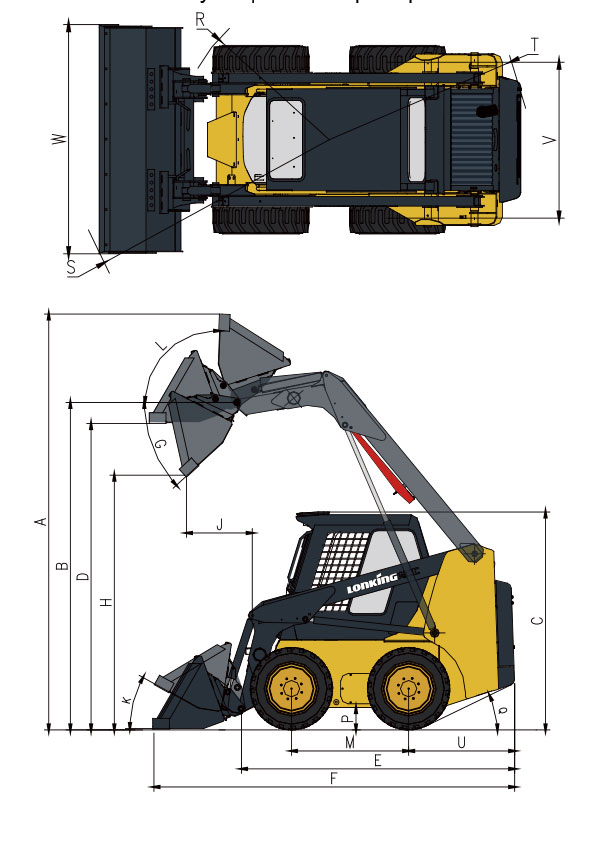
| Номер | Параметр | Ед. изм. | Значение |
|---|---|---|---|
| A | Макс. рабочая высота | мм | 3850 |
| B | Высота по креплению ковша | мм | 2920 |
| C | Высота по крыше кабины | мм | 2000 |
| D | Макс. высота при выровненном ковше | мм | 2730 |
| E | Длина без навесного оборудования | мм | 2420 |
| F | Длина со стандартным ковшом | мм | 3320 |
| H | Высота выгрузки | мм | 2180 |
| J | Вылет при разгрузке | мм | 790 |
| M | Колесная база | мм | 1050 |
| P | Дорожный просвет | мм | 210 |
| R | Радиус поворота по передним шинам без навесного оборудования | мм | 1200 |
| S | Радиус поворота по передним шинам | мм | 2060 |
| T | Радиус поворота по задним шинам | мм | 1520 |
| U | Задний свес | мм | 960 |
| V | Расстояние между центрами колес | мм | 1240 |
| W | Ширина ковша | мм | 1530 |
| G | Угол выгрузки на макс. высоте | град. | 39 |
| K | Угол наклона ковша на земле | град. | 28 |
| L | Угол возврата ковша на макс. высоте | град. | 94 |
| Q | Угол заднего свеса | град. | 27 |
CDM 308 усилинная модель с колесной базой 1080мм. Обладает небольшими габаритами и отличной маневренностью. При массе 3100 кг имеет номинальную грузоподъемность 900 кг
Погрузчик оснащен дизельным двигателем с жидкостным охлаждением V3600-E3B мощностью 50 л/с при 2600 об. мин.
Имеет гидравлическую систему 91 л/мин.
Комплектуется стандартным ковшом 0,48 м3 , также предусмотрена система быстрой смены навесного оборудования, например как: различные виды ковшей, вилы, щетки, отвал и другие.
Кабина оператора оснащена защитой от опрокидывания и падающих предметов. С внешней стороны установлены защитные решетки. Внутри удобное рабочие сидение с джойстиками управления, и встроенный обогрев всей кабины для работы холодный период времени.
Купить мини-погрузчик Lonking CDM 308 — вы можете в нашей компании (ООО “ЗТС” – официальный дилер Лонкинг на территории РФ). На мини-погрузчики предоставляется гарантия производителя 1 год или 1000 мото-часов. Также мы предлагаем широкий выбор навесного оборудования для мини-погрузчиков.
Комплектация
- Двигатель Kubota
- Главный клапан HUSCO
- Главный насос SAUER
- Насос рабочего оборудования PERMCO
- Ходовой гидромотор POCLAIN
- Кондиционер
- Механический сервопривод
- FOPS & ROPS
Опции
- Холодный запуск
- Открытая кабина
- Цельнолитые шины
- Бур
- Экскаватор
- Bevel Dweeper
- Закрытая щетка
- Вилы
- Снегоуборочный отвал
- Устройство для пересадки деревьев
- Ковш 4 в 1
- Съемные зубья ковша
- Съемная режущая кромка ковша
- Устройство для подогрева воздуха
![]()
Спецификация CDM307
Сравнение мини-погрузчиков
| Грузоподъемность | 752 кг. |
| Масса | 2700 кг. |
| Габариты (ДхШхВ) | 3320×1530×2000 мм. |
| Двигатель | XINCHAI |
| Мощность | 36.8 кВт / 50 л.с. |
| Тип управления | джойстик |
| Стандартный гидропоток | 74 л/мин |
| Высота подъема ковшевого оборудования | 2920 мм. |
| Скорость движения | 11.5 км/ч |
Погрузчик LONKING CDM 307
37’000 USD
| Грузоподъемность | 810 кг. |
| Масса | 2686 кг. |
| Габариты (ДхШхВ) | 3378×1727×1972 мм. |
| Двигатель | Kubota |
| Мощность | 36.4 кВт / 49.5 л.с. |
| Тип управления | рычаги |
| Стандартный гидропоток | 64.7 л/мин |
| Высота подъема ковшевого оборудования | 2908 мм. |
| Скорость движения | 11.8 км/ч |
Погрузчик Bobcat S510
66’000 USD
| LONKING CDM 307 | Bobcat S510 |
|---|---|
| Грузоподъемность | |
| 752 кг. | 810 кг. |
| Масса | |
| 2700 кг. | 2686 кг. |
| Габариты (ДхШхВ) | |
| 3320×1530×2000 мм. | 3378×1727×1972 мм. |
| Двигатель | |
| XINCHAI | Kubota |
| Мощность | |
| 36.8 кВт / 50 л.с. | 45.5 кВт / 61.9 л.с. |
| Тип управления | |
| джойстики | рычаги |
| Стандартный гидропоток | |
| 74 л/мин | 64.7 л/мин |
| Высота подъема ковшевого оборудования | |
| 2920 мм. | 2908 мм. |
| Скорость движения | |
| 11.5 км/ч | 11.8 км/ч |
Погрузчик LONKING CDM 307
37’000 USD
Погрузчик Bobcat S510
66’000 USD
Другие модели
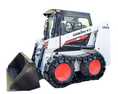
Lonking CDM308
Масса (кг)
3100
Грузоподъемность (кг)
860
Высота выгрузки (мм)
2360
Объем ковша (м3)
0.48
Подробнее
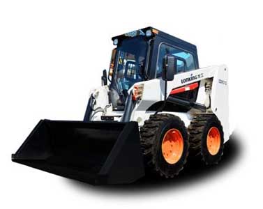
Lonking CDM312
Масса (кг)
3500
Грузоподъемность (кг)
1230
Высота выгрузки (мм)
2440
Объем ковша (м3)
0.54
Подробнее
![]()
![]()
Смотрите также
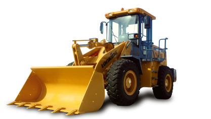
Фронтальные погрузчики
9 моделей
Грузоподъемность (кг): 1600 — 6000
Высота выгрузки (мм): 2700 — 3439
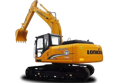
Экскаваторы
15 моделей
Высота выгрузки (мм): 4135 — 7615
Глубина копания (мм): 3762 — 16026
![]()
Официальный дистрибьютер завода LONKING (Fujian) International Trade Co., Ltd на территории России.
- →
- →
Благодаря небольшим габаритам и маневренности обладают огромным потенциалом
- Номинальная грузоподъемность: 800 кг.
- Нагрузка опрокидывания: 1740 кг.
- Эксплуатационная масса: 2800 кг.
- Высота выгрузки (по шарниру ковша): 3020 мм.
- Двигатель: XINCHAI A498BT1-175 лиц.Perkins США/КНР
- Мощность двигателя: 36,8(50) кВт(л.с.)
- Гидравлический поток: 74 л/мин
- Размер шин: 10,0-16,5
- Управление: Джойстиковое (сервопривод)
- Объем топливного бака: 83 л.
- Объем ковша в комплекте: 0,43 м3
- Скорость движения : 0–12,6 км/ч
LONKING CDM 307 — это наиболее компактная модель линейки Lonking с колёсной базой длиной в 1050 мм. При собственной массе в 2,8 т. мини-погрузчик справляется с подъёмом 800 кг в ковше и 900 кг паллетными вилами.
Благодаря небольшим габаритам и маневренности обладает огромным потенциалом в сферах промышленного применения, строительства для перемещения материала и выполнении подъемно-транспортных работ с помощью паллетных вил, коммунальной отрасли — в стесненных городских условиях для уборки территории, а также в сельском хозяйстве.
Кабина c защитой от опрокидывания (ROPS) и падающих предметов (FOPS) отличается большим внутренним пространством и высокой эргономикой. Прекрасная обзорность в 360 градусов достигается благодаря узким стойкам кабины, широким остеклением и прозрачностью боковых частей кабины и фронтальной двери. Эвакуационный выход совместно с широкими боковыми зеркалами заднего вида дают дополнительный угол обзора.
Эргономика внутри кабины продумана до мелочей: защитные решетки с внешней стороны, ниша под документы, подстаканник. Удобное эргономичное сиденье, позволяет оператору эффективно выполнять свои функции длительное время, а электронная информационная панель упрощает процессы управления: все «жизненно» важные параметры работы погрузчика, а именно температура охлаждающей жидкости в системе охлаждения, давление моторного масла, смазывающего детали двигателя, нагрев рабочей жидкости в гидросистеме машины, оператор видит перед собой на мониторе.
Отличная шумо- и виброизоляция кабины надёжно защищает оператора от влияния этих вредных факторов. Также делает его пребывание на рабочем месте комфортным в холодную погоду наличие в кабине мощного автономного отопителя, обеспечивающего благоприятную температуру в кабине.
В качестве главного привода используется дизельный двигатель с жидкостным охлаждением мод. A498BT1-175 мощностью 50,0 л.с., изготовленный китайской компанией Zhejiang Xinchai Co. Ltd по аналогии с американской компанией Perkins. Компания Xinchai является одним из ведущих в Китае производителем в сегменте многоцилиндровых дизельных двигателей для сегмента погрузчиков грузоподъемностью от 1 до 4 т.
Надёжной работе мотора способствует и использование многоступенчатой системы фильтрации топлива, используемой в базовой комплектации инженерами Lonking. Применение в топливной системе эффективного современного распределительного ТНВД роторного типа, отличающегося компактными размерами и небольшим весом, также улучшает показатели работы двигателя.
Мини-погрузчик оснащён стандартным ковшом 0,45 куб. м. Высота разгрузки по пальцу ковша составляет 3 020 мм., что позволяет погрузчику производить загрузку самосвалов с высокими бортами.
Погрузчик имеет конструкцию быстрой смены навесного оборудования BobTach, используются быстроразъёмные гидравлические соединения, как и в погрузчиках европейских брендов.
Это означает, что оператор может в течение короткого времени произвести смену навесного оборудования и устанавливать на стрелу мини-погрузчика навесное оборудование как европейского, так и российского производства.
Гидравлическая система с расходом в 74 л/мин позволяет эффективно работать с различными видами ковшей и вил, использовать мини-экскаватор, подметальную цилиндрическую щетку, бетоносмеситель, дорожную фрезу, гидробур, гидромолот, отвал, снегоротор и более 30 видов навесных агрегатов.
Управление погрузчиком производится с помощью двух джойстиков, связанных с гидрораспределителем посредством сервопривода. Каждый джойстик отвечает за гидромотор, сообщающий вращение колёсам одной стороны машины с помощью цепной передачи. Цепной привод создаёт максимальную тяговую мощь погрузчиков.
В систему управления всех моделей Lonking встроена система выравнивания ковша в горизонтальной плоскости, что чрезвычайно облегчает транспортировку грузов в ковше на небольшие расстояния. Также в блок управления погрузчиков интегрированы система защиты от перегруза, система электрического парковочного тормоза, а также система аварийного отключения гидравлики. Также, с целью повышения безопасности труда, при открывании двери в кабину, срабатывает концевой выключатель и работа гидравлической системы также блокируется.
В погрузчике используется круговая замкнутая статическая гидравлическая система. В базовой комплектации устанавливаются гидронасосы марки Sauer-Danfoss, европейского или североамериканского производства. Все рукава высокого давления поставляет итальянский бренд Manuli Hydraulics, а гидромоторы приобретаются у знаменитой американской компании Poclain.
Гидрораспределитель используется китайского производства, но изготовленный по лицензии немецкой компании Husco. Также и шестерёнчатые насосы, используемые в конструкции: они выпускаются известной китайской компанией Permco по лицензии немецкой компании Sauer-Danfoss.
Удобство технического обслуживания повышено благодаря откидывающейся вперед кабине, что дает доступ ко всем агрегатам машины, а также логичному расположению узлов для проведения сервисного обслуживания.
Хорошо продумана в минипогрузчиках и возможность технического обслуживания элементов силового блока: в рабочем положении кабина зафиксирована одним болтом, находящимся внутри кабины. Но, открутив этот болт, оператор легко может поднять кабину, открывая, таким образом, полный доступ к силовой установке и элементам гидросистемы с фронтальной стороны машины. Очень простой и удобный доступ к моторному отсеку с тыльной части машины позволяет системно проводить контроль технического состояния двигателя и других компонентов силового блока в любое время.
Базовый комплект поставки погрузчиков компании Lonking предусматривает установку безопасной и обзорной кабины c защитой от опрокидывания (ROPS) и падающих предметов (FOPS), эргономичного сиденья, джойстикового управления посредством сервопривода, кондиционера (на всех моделях CDM312) и отопителя, бескамерных шин типоразмера 10-16.5, боковых зеркал заднего вида, электронной панели приборов, проблескового маячка, поворотников, наружного освещения спереди и сзади, сигнала заднего хода.
«LONKING HOLDINGS LIMITED» на территории Российской Федерации запустила программу по продлению гарантии на все погрузчики Lonking до 2 лет либо 3 000 м/ч в зависимости от того, что наступит ранее.
Гарантия предоставляется в случае подписания клиентом договора Сервисного обслуживания и проведение регламентных ТО с помощью сервисной службы каждые 250м/ч.
Доставляем погрузчики Lonking в любой регион. Четко соблюдаем нормы и правила безопасного перемещения. Все погрузчики проходят тщательную подготовку перед отправкой.
Модельный ряд мини-погрузчиков Lonking
Минипогрузчик Lonking CDM307 – начальная модель в линейке надежных и недорогих китайских погрузчиков Лонкинг с бортовым поворотом. Модель имеет грузоподъемность 752 кг, эксплуатационную массу 2700 кг, объем ковша 0,43 м3 и может комплектоваться по выбору покупателя двигателями Kubota или Xinchai. Подъем рамы – радиальный, высота выгрузки — 2180 мм.
Полный привод и способность колес правого и левого бортов вращаться одновременно в противоположных направлениях дает возможность мини-погрузчику поворачивать на месте, что делает погрузчик CDM307 максимально маневренным, и позволяет эффективно выполнять работы в условиях ограниченного пространства.
Компания Lonking является лидером продаж на российском рынке погрузчиков среди всех китайских производителей, что свидетельствует о высоком качестве продукции бренда.
Купить минипогрузчик Lonking CDM307 – вы можете в нашей компании (ООО “ЗТС” является официальным дилером Lonking на территории РФ). Наши сотрудники помогут с выбором комплектации и подбором необходимого навесного оборудования
Комплектация
- Двигатель Kubota
- Главный клапан HUSCO
- Главный насос SAUER
- Насос рабочего оборудования PERMCO
- Ходовой гидромотор POCLAIN
- Кондиционер
- Механический сервопривод
- FOPS & ROPS
Опции
- Холодный запуск
- Открытая кабина
- Цельнолитые шины
- Бур
- Экскаватор
- Bevel Dweeper
- Закрытая щетка
- Вилы
- Снегоуборочный отвал
- Устройство для пересадки деревьев
- Ковш 4 в 1
- Съемные зубья ковша
- Съемная режущая кромка ковша
- Устройство для подогрева воздуха

Уважаемый Клиент!
Меня зовут Курило Никита, я – руководитель отдела продаж компании ООО «СпецТехника».
Мы являемся официальным дистрибьютором завода Lonking на всей территории России. Реализуем новые мини погрузчики напрямую с завода производителя, без посредников, на это имеются все необходимые сертификаты и разрешения.
Мы совместно с заводом приняли решение оставить цены максимально доступными по сравнению с другими производителями и продлить гарантию на все погрузчики до 3 лет либо 3 000 м/ч.
Сегодня цены на погрузчики Lonking остаются максимально доступными, несмотря на рост доллара США по отношению к рублю и повышение ставок на утилизационный сбор.
Скидка действительна на весь модельный ряд погрузчиков
>>> LONKING модель CDM307
Грузоподъемность – 800 кг. Ковш в комплекте.
Цена 2 850 000 руб. 2 650 000 руб. В наличии 2 ед.
>>> LONKING модель CDM308
Грузоподъемность – 900 кг. Ковш в комплекте.
Цена 2 980 000 руб. 2 750 000 руб. В наличии 4 ед.
>>> LONKING модель CDM312
Грузоподъемность – 1230 кг. Ковш в комплекте.
Цена 3 950 000 руб. 3 700 000 руб. В наличии 2 ед.
Предлагаем воспользоваться уникальной ситуацией для покупки прямо сейчас. Не ждите, пока падение рубля и растущие ставки на таможенный сбор приведут к неизбежному повышению стоимости оборудования и как следствие к обесцениванию денег.
* Цена с НДС по прайс-листу и утилизационным сбором при курсе не более 67 рублей по отношению к доллару США.
Отличительные особенности мини погрузчиков LONKING CDM307/308/312:
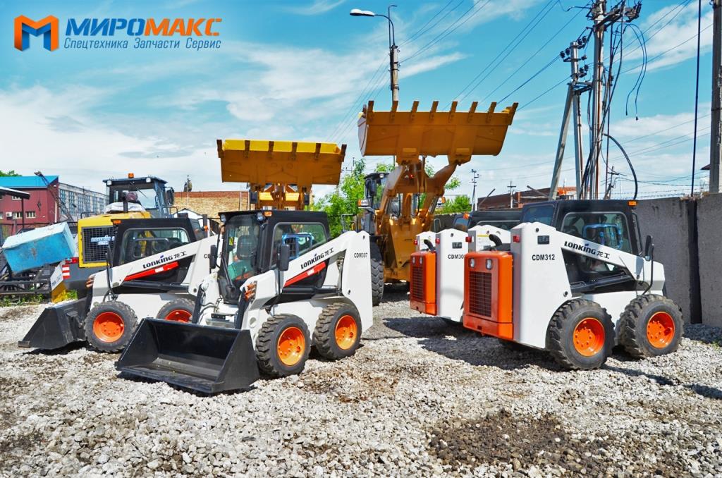
- В стандартной комплектации джойстиковое управление с механическим сервоприводом
- В стандартной комплектации ковш объёмом 0,43 м3
- Импортная гидравлическая система, включающая: гидромоторы POCLAIN(Европа), гидронасос SAUER DANFOSS (США/Европа), гидрораспределитель HUSCO(Германия/КНР), рукава высокого давления MANULLI (Италия)
- Кабина оборудованная дополнительной шумо/теплоизоляцией
- Кабина оборудована кондиционером и отопителем.
- Все масла и жидкости, используемые в погрузчиках приспособлены к суровым климатическим условиям России
- Имеется электронный стояночный тормоз
- Интегрирована система аварийного отключения гидравлики
- Интегрирована система защиты от перегруза
- Улучшенная гидросистема. Делает перемещение стрелы более точными и плавными.
- Система автоматического выравнивания ковша. При подъеме стрелы ковш автоматически сохраняет горизонтальное положение.
- Защитная кабина ROPS&FOPS. Просторная кабина с отличным обзором. Защита от падения груза сверху и опрокидывания.
Технические параметры мини погрузчиков Lonking CDM307/308/312
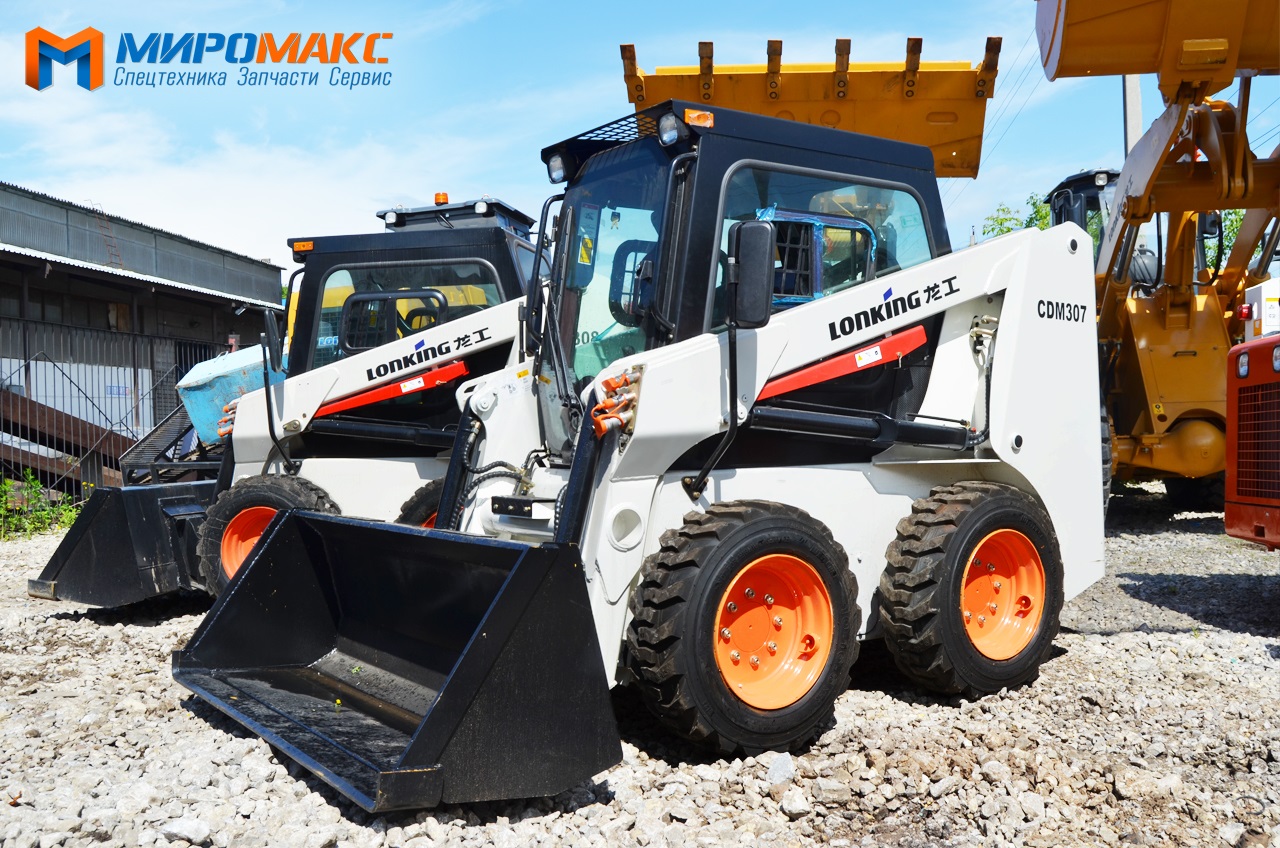
Мини погрузчик Lonking CDM307
- Номинальная грузоподъемность: 800 кг.
- Нагрузка опрокидывания: 1740 кг.
- Эксплуатационная масса: 2800 кг.
- Высота выгрузки (по шарниру ковша): 2920 мм.
- Двигатель: XINCHAI A498BT1-175 лиц.Perkins США/КНР
- Мощность двигателя: 36,8(50) кВт(л.с.)
- Гидравлический поток: 74 л/мин
- Размер шин: 10,0-16,5
- Управление: Джойстиковое (сервопривод)
- Объем топливного бака: 83 л.
- Объем ковша в комплекте: 0,43 м3
- Скорость движения : 0–12,6 км/ч
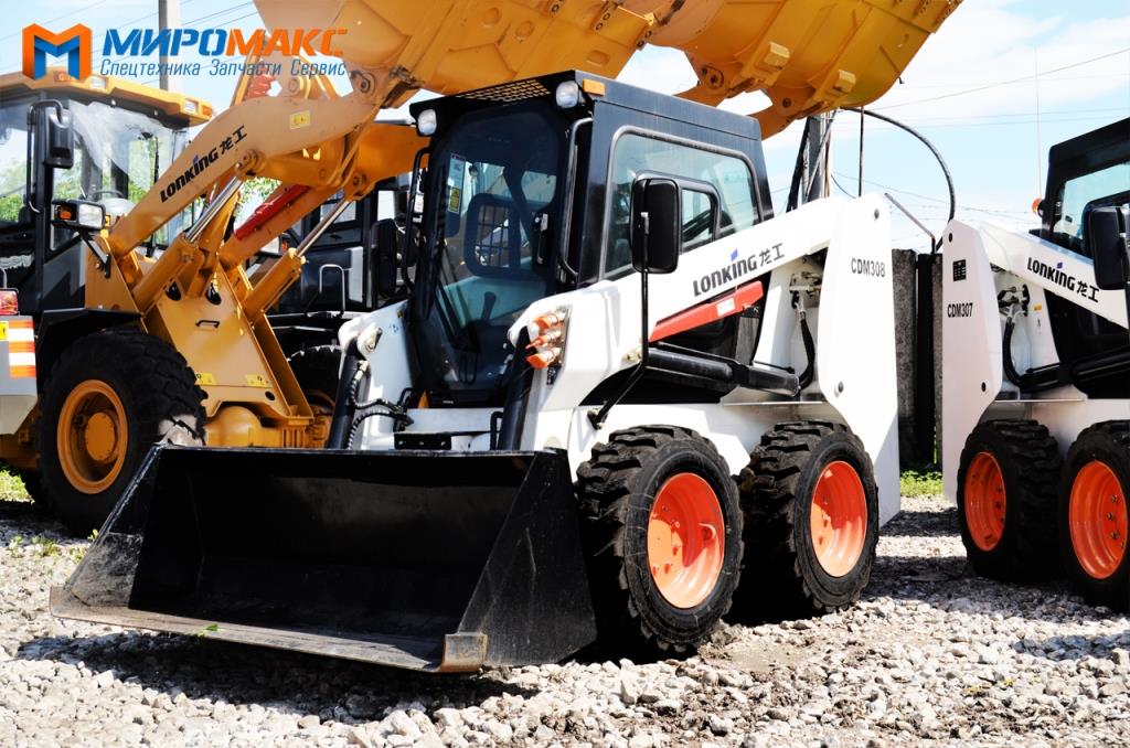
Мини погрузчик Lonking CDM308
- Номинальная грузоподъемность: 900 кг.
- Нагрузка опрокидывания: 1820 кг.
- Эксплуатационная масса: 3000 кг.
- Высота выгрузки (по шарниру ковша): 3020 мм.
- Двигатель: XINCHAI A498BG-510 лиц.Perkins США/КНР
- Мощность двигателя: 45(60) кВт(л.с.)
- Гидравлический поток: 74 л/мин
- Размер шин: 10,0-16,5
- Управление: Джойстиковое (сервопривод)
- Объем топливного бака: 83 л.
- Объем ковша в комплекте: 0,43 м3
- Скорость движения : 0–12,6 км/ч
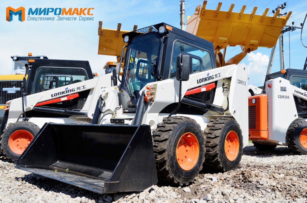
Мини погрузчик Lonking CDM312
- Номинальная грузоподъемность: 1230 кг.
- Нагрузка опрокидывания: 2460 кг.
- Эксплуатационная масса: 3700 кг.
- Высота выгрузки (по шарниру ковша): 3060 мм.
- Двигатель: XINCHAI A498BZG лиц.Perkins США/КНР
- Мощность двигателя: 55(75) кВт(л.с.)
- Гидравлический поток: 91 л/мин
- Размер шин: 12,0-16,5
- Управление: Джойстиковое (сервопривод)
- Объем топливного бака: 83 л.
- Объем ковша в комплекте: 0,6 м3
- Скорость движения : 0–12,6 км/ч
Сравнительная таблица Lonking CDM307/308/312
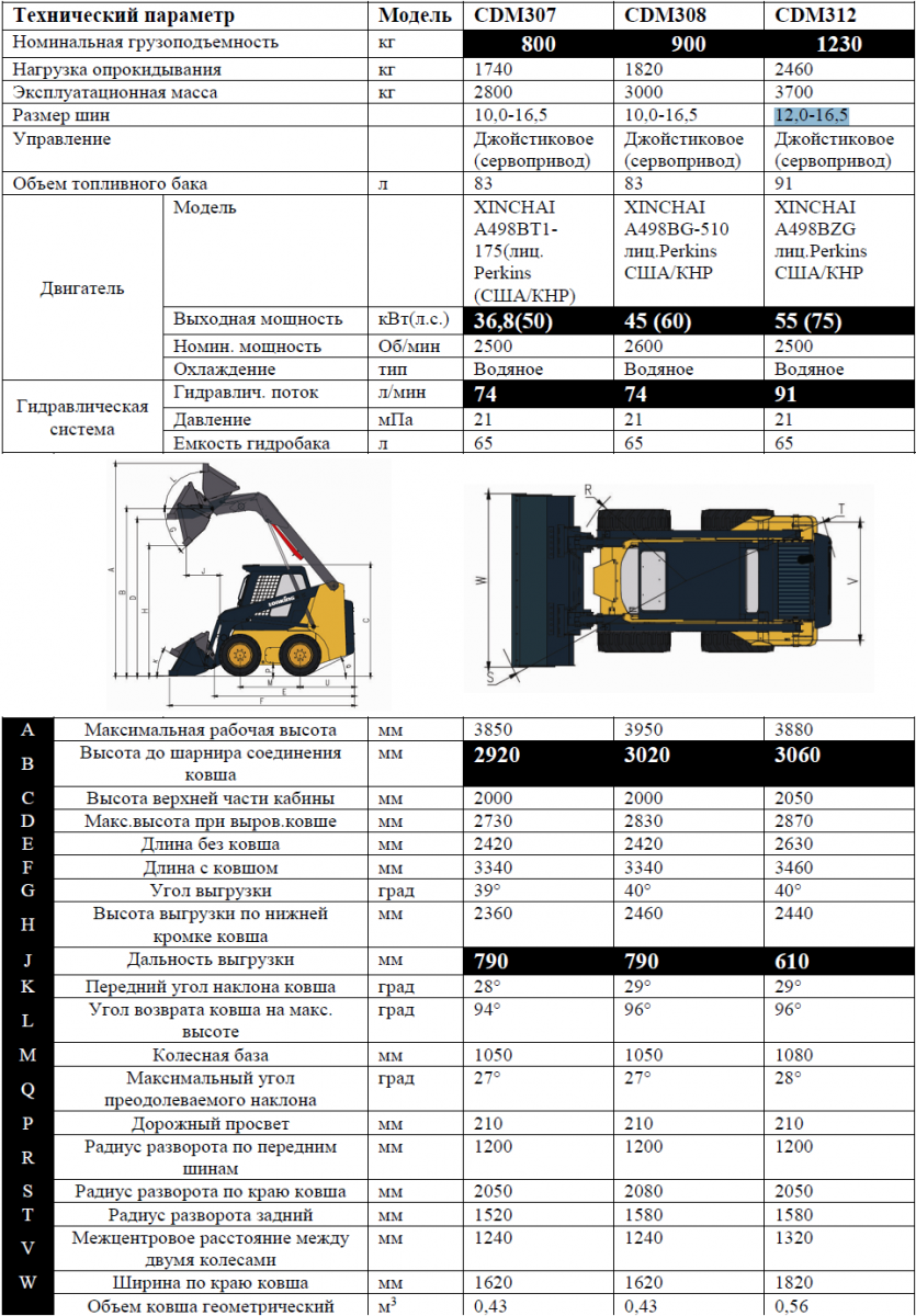
Надежные и экономичные 4-х цилиндровый дизельные двигатели производства Xinchai модель A498, изготовляемый по лицензии Perkins(США), объемом от 2,5 л. с жидкостным охлаждением, мощностью от 36,8 кВт. (50 л.с.) до 68 кВт. (93 л.с.), Под заказ возможна поставка мини погрузчиков Lonking c оригинальным двигателем KUBOTA (Япония). В стандартной комплектации машины существует многоступенчатая система фильтрации топлива. АКБ увеличенной емкости. ТНВД роторного типа, что позволяет «кушать» солярку практически любого качества, что в наших условиях несомненный плюс. Уровень токсичность отработанных газов соответствует приводимым ниже нормативным положениям.
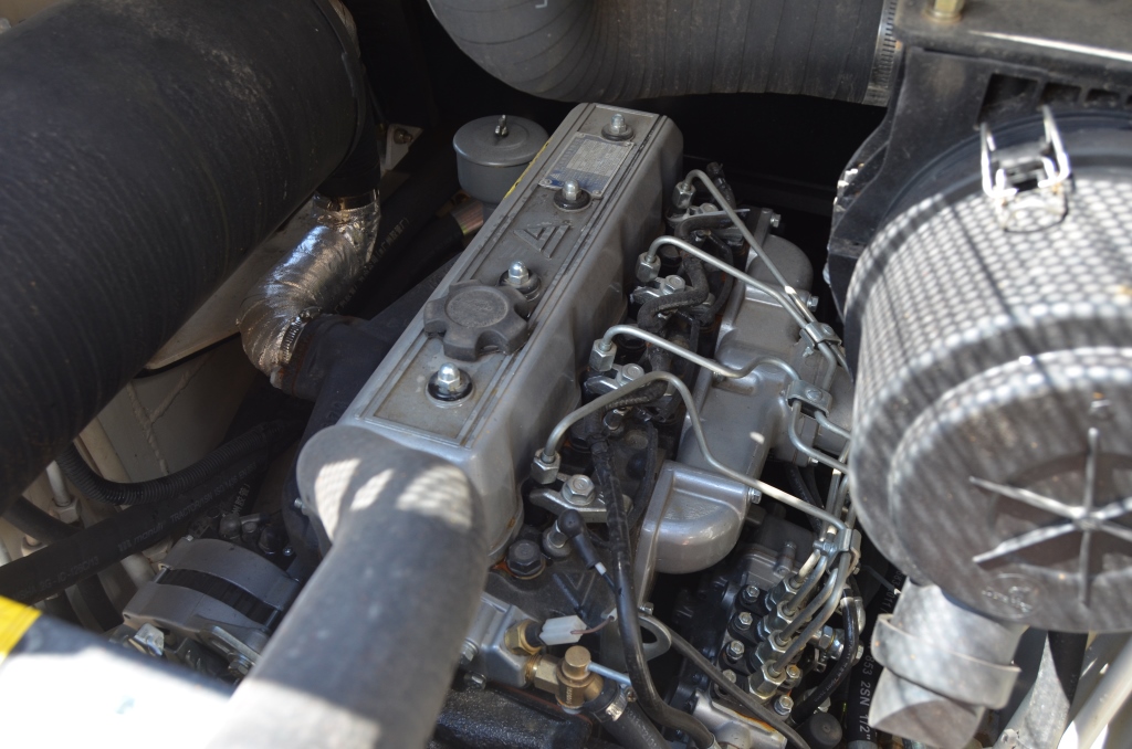
Согласно европейским требованиям, запуск двигателя возможна даже при -50°C. Во-первых, свечи накаливания с таймером для уверенного пуска в холодный период, он включается на 30 секунд при повороте ключа зажигания в обратную сторону. Во-вторых, есть возможность установки электрического предпускового подогревателя от 220 вольт., так и автономного предпускового подогревателя типа Webasto. Доступ к двигателю простой – откидывается верхняя крышка, компоновка просторная, все под рукой.
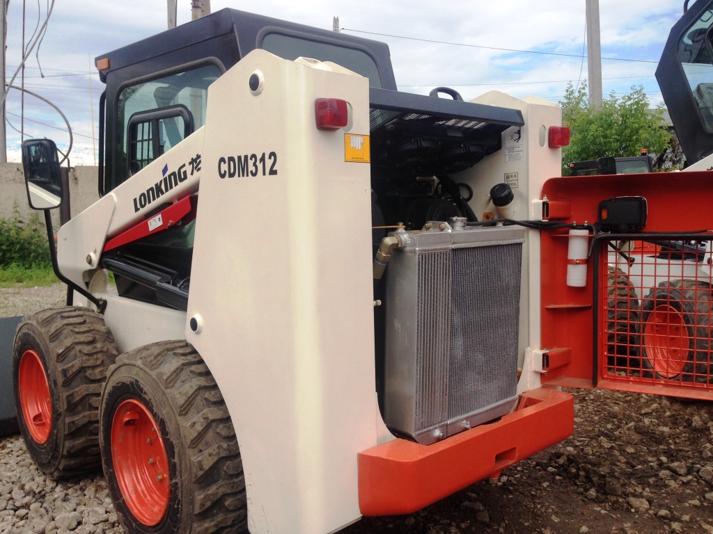
Для улучшения доступа ко всем узлам и агрегатам можно приподнять кабину, открутив один фиксирующий болт.

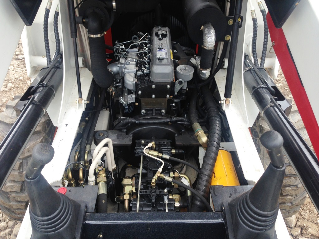
Гидравлическая система – это основная часть универсальных мини-погрузчиков, от которой напрямую зависит производительность.
- Гидравлич. поток 74 л/мин. для моделей CDM307/308 и 91 л/мин. для CDM312
- Давление 21 мПа
- Емкость гидробака 65 л.
Под заказ возможна поставка мини погрузчиков Lonking с усиленным гидропотоком в 135 л/мин
Мини-погрузчики Lonking оборудуются импортными узлами и агрегатами:
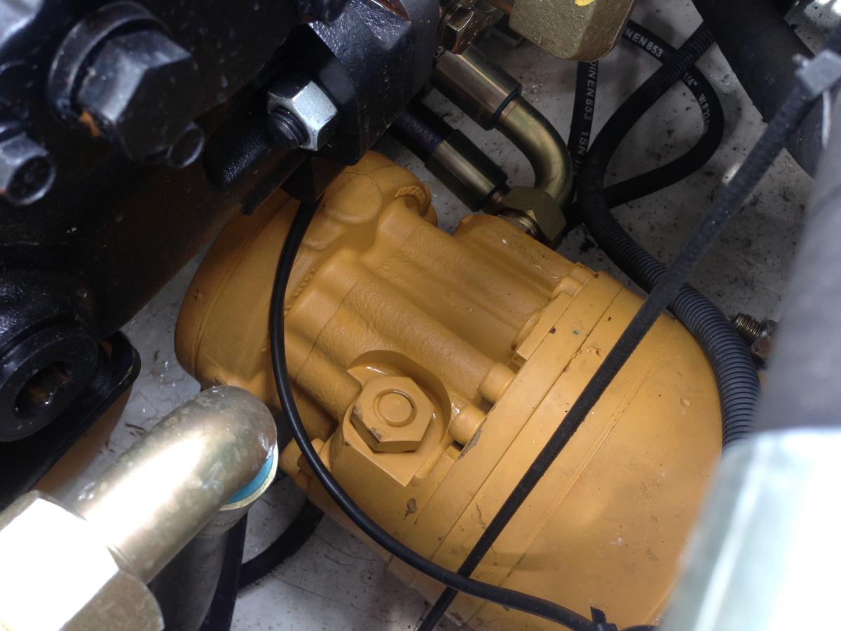
Гидронасосы – Sauer Danfoss (Европа)
Рабочий гидрораспределитель – HUSCO (Германия/КНР)
Гидромоторы Poclain (США)
Рукава высокого давления MANULLI (Италия)
Шестеренчатые насосы – Permco от Sauer (Германия/США)
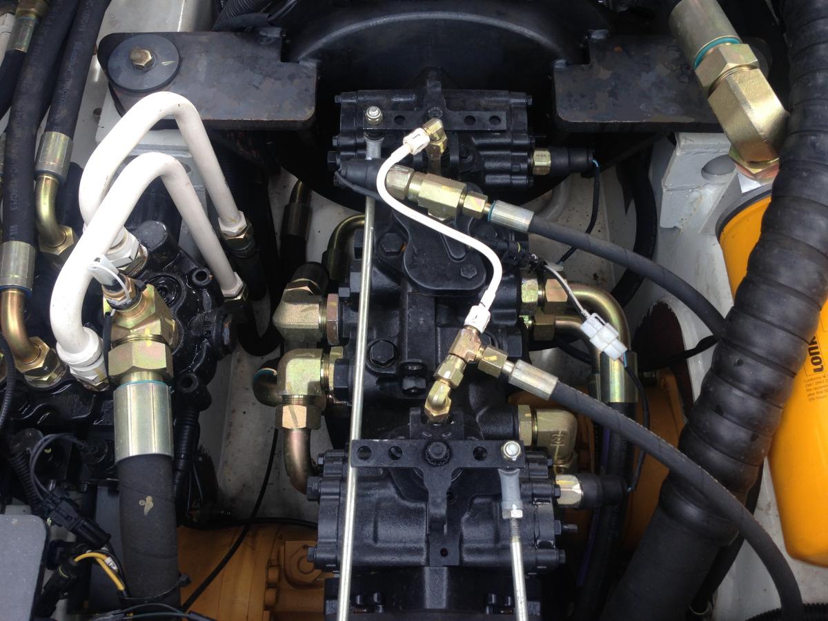
Управление и интерьер мини погрузчика Lonking CDM307/308/312
Минипогрузчики Lonking управляются двумя джойстиками связанных с гидрораспределителем посредством сервопривода. Например, правый поворот – это отклонение левого джойстика вперед, а правого назад. Двигаться вперед/назад можно наклонив оба джойстика также вперед/назад.
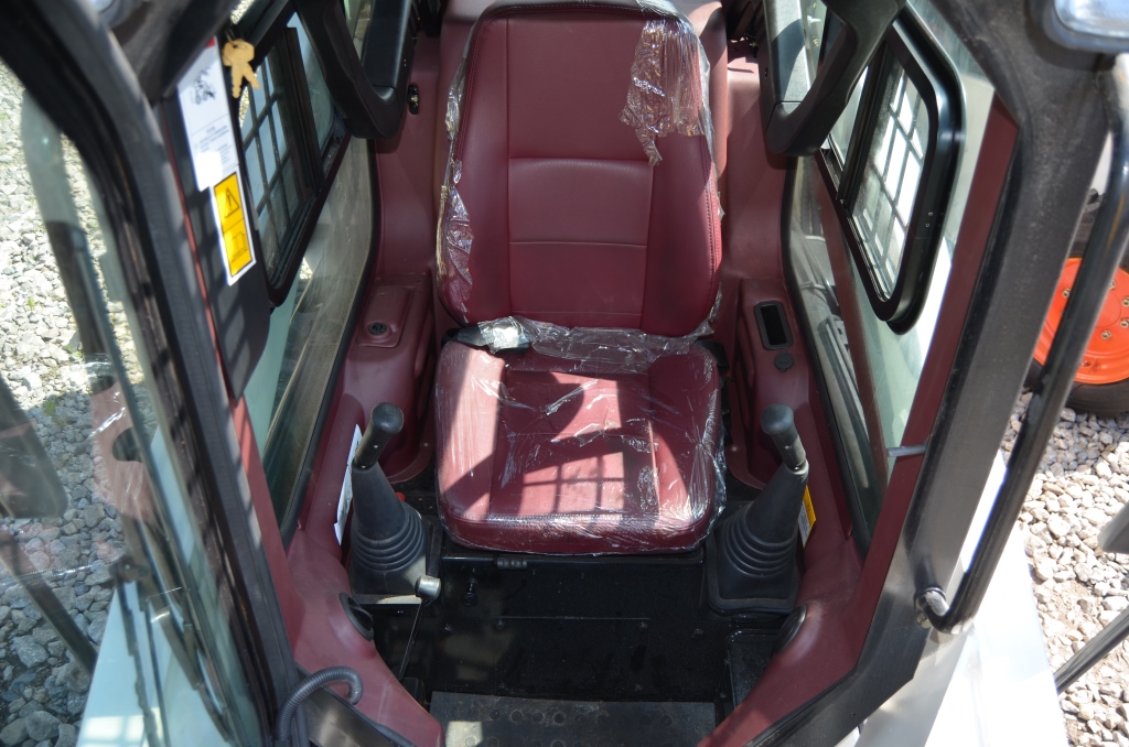
Газ регулируется с помощью ножной педали, но точнее дозировка газа ручным рычагом (находится справа от оператора). Управление простое и интуитивно понятное. Правый джойстик управляет опусканием/поднятием стрелы с ковшом. Левый джойстик изменяет наклон ковша: захватить грунт или высыпать его. На правом джойстике кнопка сигнала. Если оператор встает с кресла, то срабатывает «датчик безопасности», отключающий джойстики. Пока оператор не сядет в кресло, никаких действий не последует даже при работающем двигателе.
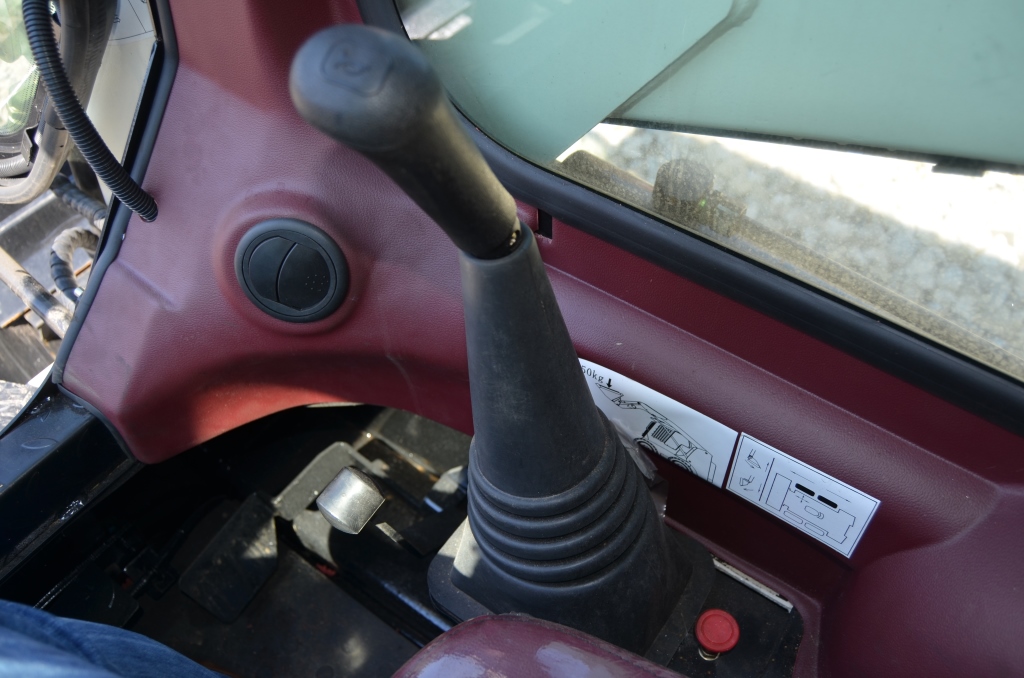
Защитная кабина ROPS&FOPS выполнена согласно международным стандартам безопасности, обеспечивает максимальный уровень комфорта и защиты для оператора от падения груза сверху и опрокидывания.
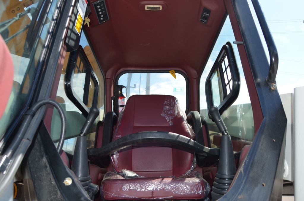
Высокая степень остекления кабины обеспечивают хороший обзор рабочей зоны, а зеркала заднего вида дают возможность обозревать пространство позади машины, дает максимально возможную безопасность при выполнении работ. Высококлассная шумо и вибро изоляция двигателя резко снижает утомляемость оператора, позволяя с легкостью работать сверх нормы. В кабине установлено удобное эргономическое регулируемое сиденье с ремнем безопасности, позволяющее работать на погрузчике длительное время.

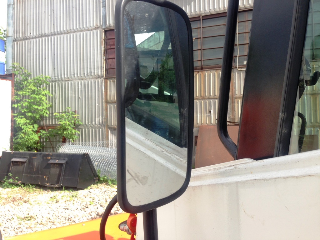
Из кабины осуществляется контроль над всеми жизненно важными функциями минипогрузчика, такими, как температура охлаждающей жидкости двигателя, давлением масла двигателя и температура гидравлического масла. Присутствует фонарь освещения кабины, бардачек для мелких инструментов и предметов, прикуриватель.
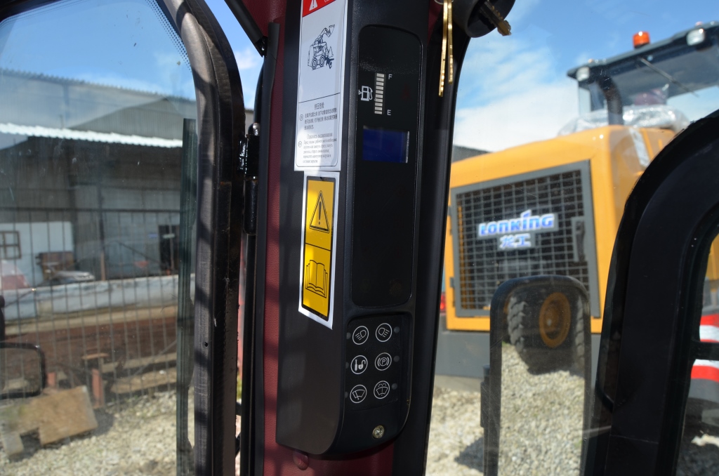
Мини-погрузчики Lonking оснащены герметичной закрытой кабиной. Кабина оборудована отопителем и кондиционером, что делает работу оператора комфортной, как в холодное время года, так и в жаркие дни лета.
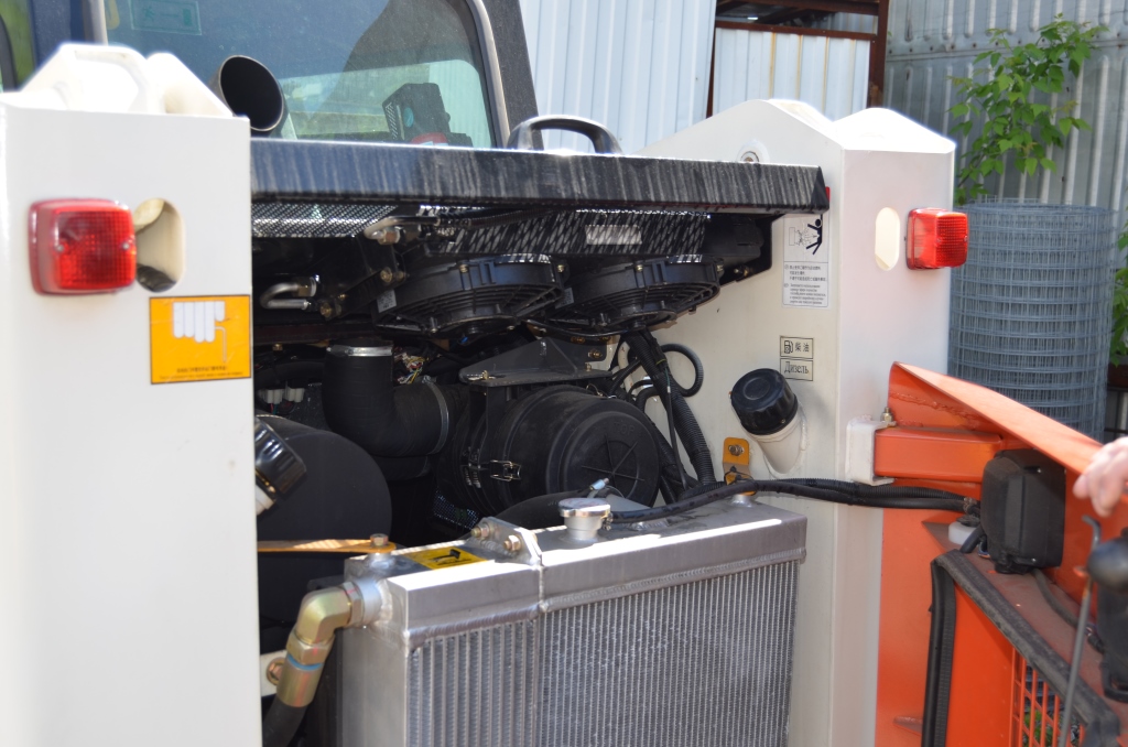
Подъемная рама минипогрузчиков Lonking CDM307/308/312
Подъемная мачты выполнена из специального профиля, который обеспечивает отличный обзор. Устройство крепления навесного оборудования выполнено в быстросъемном исполнении SSL. Это позволяет менять одно навесное оборудование на другое за считанные минуты, и не требует физических усилий.
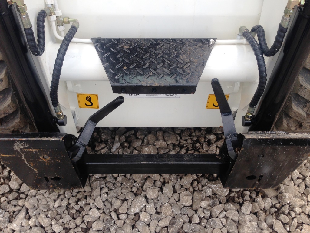

Для увеличения проходимость возможно дооборудование погрузчика накидными гусеницами, а благодаря наличию дополнительных гидролинии возможно использование любого навесного оборудования:
отвал, снегоочиститель, траншеекопатель и много другое.
Установлены системы автоматического выравнивания ковша, система защиты от перегрузки, система аварийного отключения гидравлики
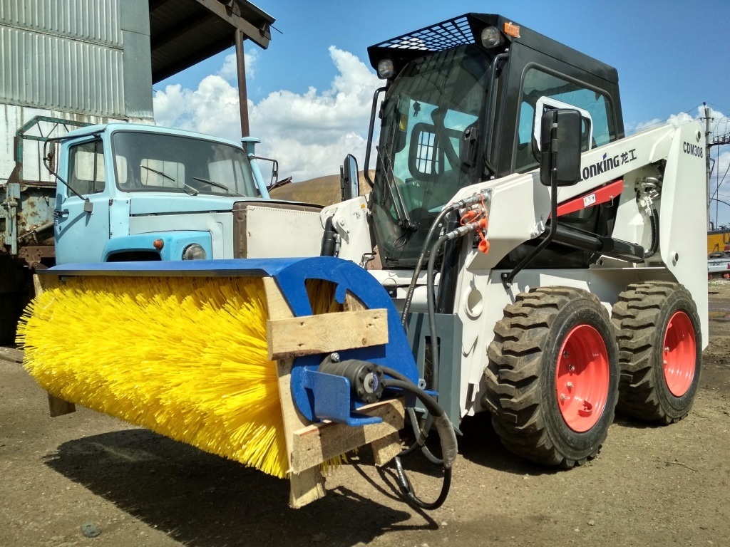
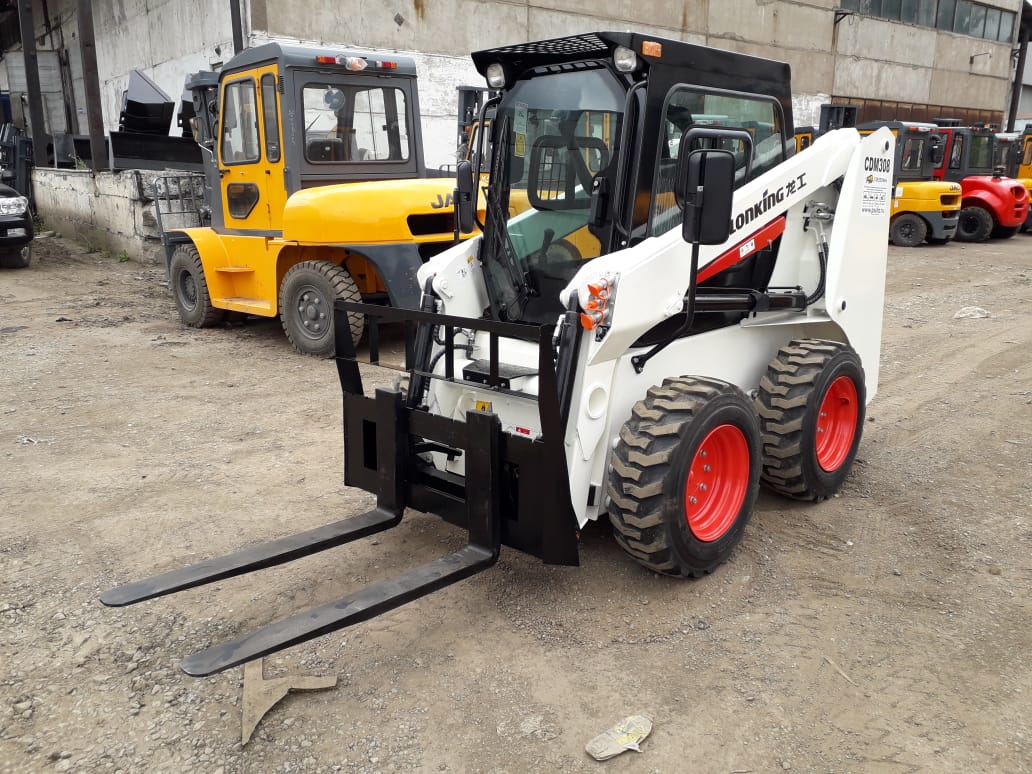
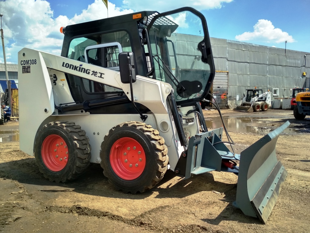
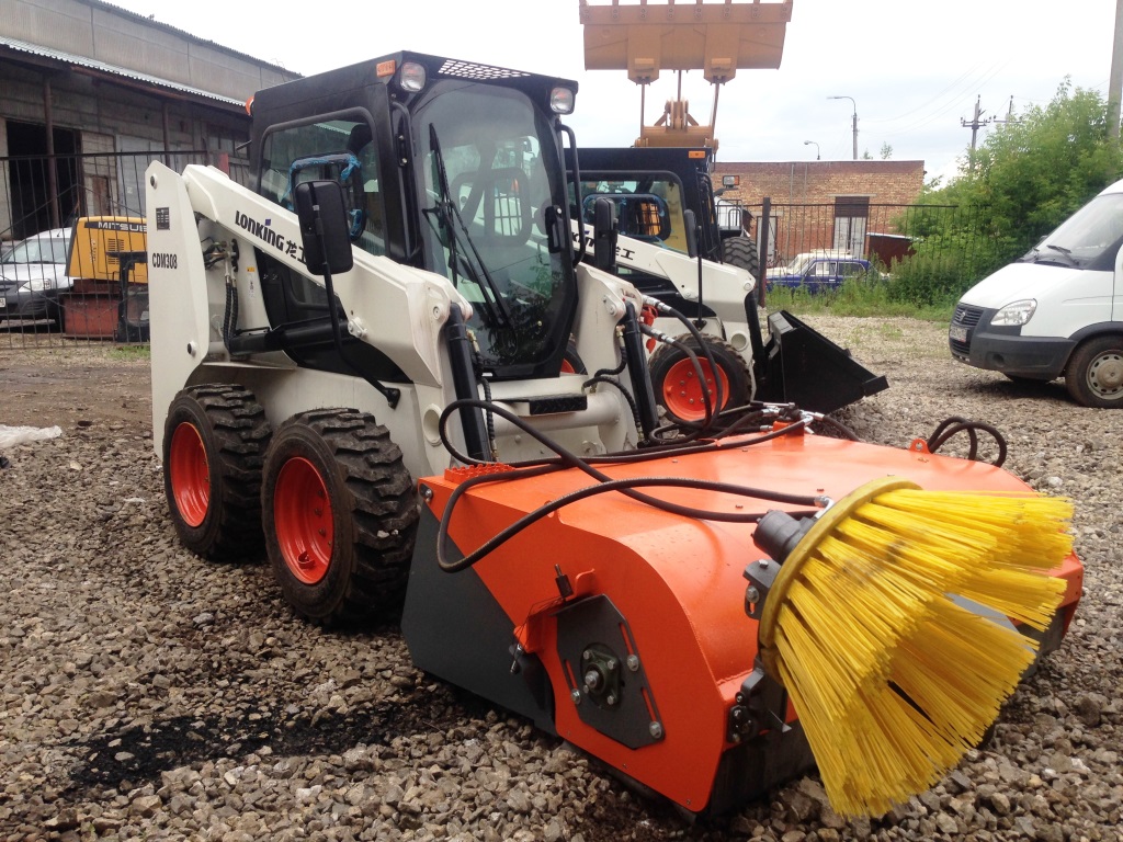
Тем самым по своей расширенной функциональности мини-погрузчики Lonking способны сравниться с целым парком коммунальной техники. Необходимо лишь выбрать соответствующее навесное оборудование. Максимальная высота выгрузки 3060 мм., позволяет использовать Мини погрузчики Lonking для загрузки самосвалов при любой работе.

Стандартная комплектация мини-погрузчиков Lonking CDM307/308/312:
- Безопасная и обзорная кабина ROPS/POPS
- Система автоматического выравнивания ковша
- Освещение внутри кабины
- Отопитель и кондиционер
- Электронная информативная панель
- Проблесковый маячок
- Зуммер (звуковой сигнал) заднего хода
- Удобное сиденье с рамой безопасности
- Ручной и ножной акселератор
- Стояночный тормоз
- Рабочее наружное освещение спереди и сзади
- Стандартный ковш
- Джойстиковое управление с сервоприводом
- Система аварийного отключения гидравлики
- Система защиты от перегрузки
- Вспомогательные гидравлические быстроразъемные соединения
- Быстросъемная система смены навесного оборудования SSL
- Рукава высокого давления MANULLI (Италия)
- Высокопроизводительный двигатель Xinchai(КНР) выполненный по лицензии Perkins (США-КНР)/ либо KUBOTA (Япония)
- Пневматические износостойкие шины ARMOUR RG400
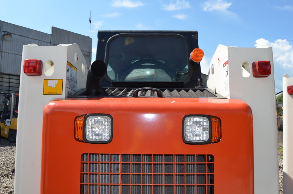
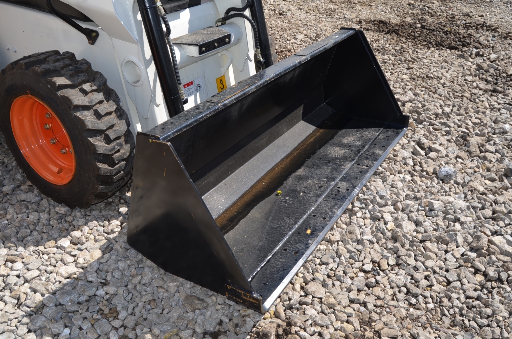
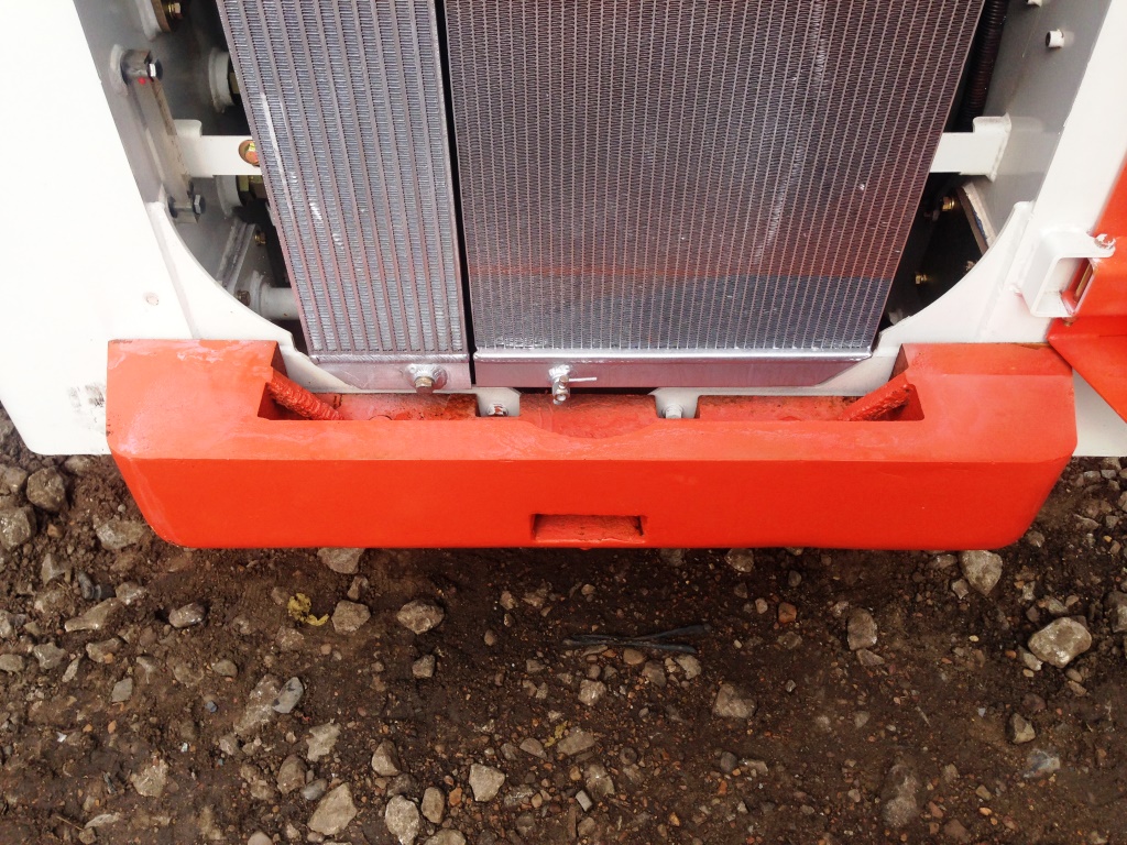
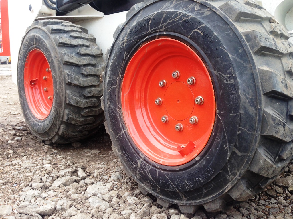
Гарантия на мини погрузчики Lonking CDM307/308/312
На все новые универсальные мини-погрузчики LONKING, предоставляется гарантия 3 года или 3000 м/ч, в зависимости от того, что наступит ранее. Гарантия предоставляется при условии заключения договора на сервисное обслуживание. Без заключения договора на обслуживание гарантия 12 месяцев или 2000 м/ч. Постпродажное обслуживание универсальных мини-погрузчиков LONKING производится на всей территории РФ.
Запасные части на мини погрузчики Lonking CDM307/CDM308/CDM312
Мы располагаем собственным складом запасных частей, насчитывающий более 1000 позиций и общей стоимостью 13 500 000 руб.
Доставка мини погрузчика Lonking в любой регион
Партнерские отношения с крупными транспортными компаниями позволяют нам быстро доставить погрузчики в любую точку России от Калининграда до Южно-Сахалинска. Четко соблюдаем нормы и правила безопасного перемещения. Все погрузчики проходят тщательную подготовку перед отправкой.
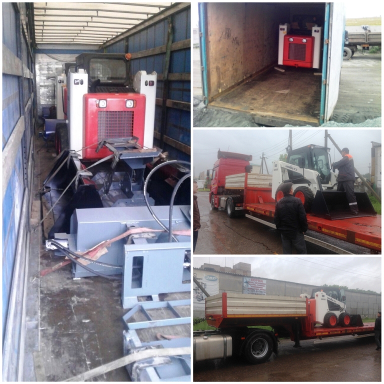
Не_откладывайте!
Другие производители уже повысили цены на 10-30% и это похоже не предел. И мы вынуждены будем повышать цены. Если Вы планируете пополнить склад спецтехники, предлагаем воспользоваться уникальной ситуацией для покупки прямо сейчас. Не ждите, пока падение рубля приведет к неизбежному повышению стоимости оборудования и как следствие к обесцениванию денег.
Остались вопросы или вы готовы сделать заказ? Позвоните нам +7(927)-236-04-53 склад Уфа