Как устроен наркозно-дыхательный аппарат Mindray WATO EX-35
26 мая 2023
Наш телеграм-канал: https://t.me/medfordservice
Как работает НДА
Для обеспечение корректной работы наркозно дыхательного оборудования в клинике, где он находится, первым делом должны быть соответствующие коммуникации: источники газоснабжения, трубы и шланги разного диаметра, настенные разъемные розетки, а также система вывода отработанных газов.
Источником газов являются баллоны, в которых находятся O2 и N2O. Первое, что встречает газ на своем пути, это редуктор, чтобы подаваться под оптимальным давлением. Газы после редуктора проходят через дозиметры, которые нужны для точного подбора дозировки каждого компонента газовой смеси. Они точно показывают, сколько литров в минуту газа подается через аппарат.
Помимо всего этого в НДА должны быть:
- Испарители — средства для дозированной подачи жидких анестетиков, в которых происходит испарение веществ
- Дыхательный контур (или контур пациента), обеспечивающий подачу и вывод газовой смеси от дозиметров и испарителей в дыхательные пути пациента
- Адсорбер, в котором происходит поглощение углекислого газа натронной известью.
Основными задачами наркозного аппарата являются: дозирование анестетика, приготовление и циркуляция газовой смеси и поддержание постоянства ее состава, а также проведение искусственной вентиляции легких.
Общую схему устройства наркозного аппарата можно себе представить так: к аппарату через понижающие редукторы подключаются баллоны с O2 и N2O. Их подача регулируются с помощью дозиметров. Далее газовая смесь проходит через испаритель, в которой обогащаются парами анестетиков до определенной концентрации, после смесь поступает в дыхательный контур (он же контур циркуляции газов).

С помощью клапанов вдоха (5) и выдоха (6) и дыхательного мешка для нагнетания газовой смеси, газ циркулирует по контуру только в одну сторону, постоянно обновляясь, за счет:
- поглощения в организме пациента кислорода и части анестетика,
- выделения им углекислого газа,
- поглощения углекислого газа в адсорбере
- подаче в контур новых порций газовой смеси.
Клапан сброса (7) обеспечивает удаление излишков наркозно-дыхательной смеси при превышении установленного давления.
Стандартное оснащение WATO EX-35
Первое, на что падает наш взгляд это рабочая панель. На ней расположены флоуметры.
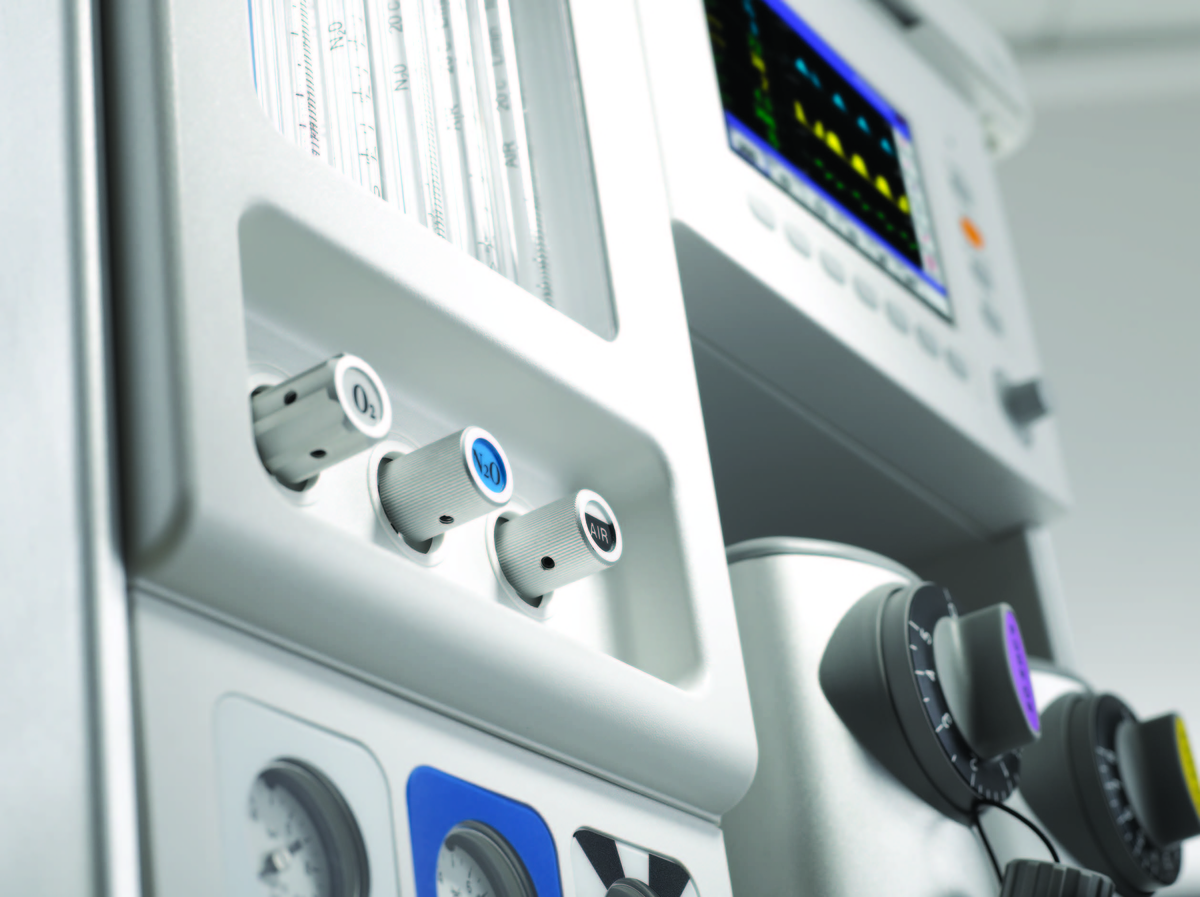
С помощью регуляторов под флоуметрами мы можем контролировать уровень подачи газов: воздуха, O2 и N2O. Ниже расположены манометры, которые показывают давление газов.
Справа от флоуметров находится рабочий сенсорный экран диагональю 10,4 дюйма. Он также оснащен индикатором тревоги.
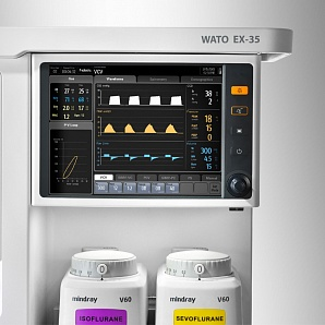
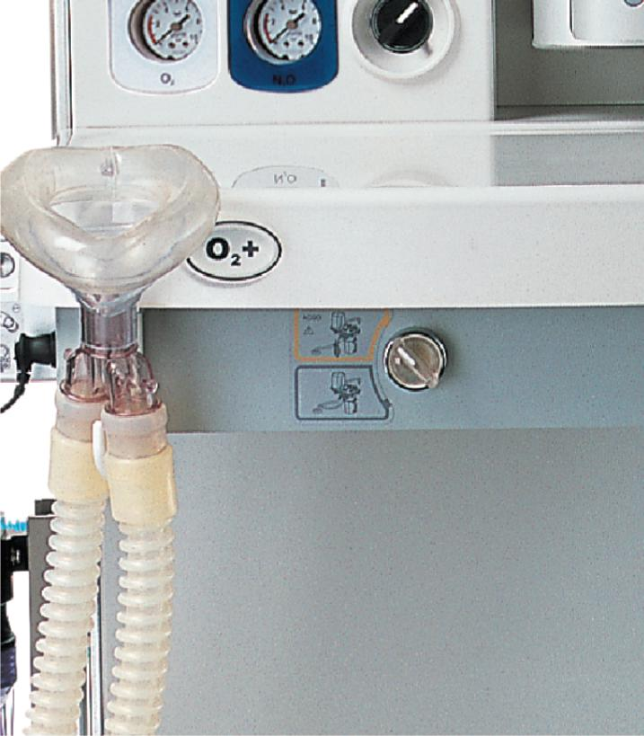
Под сенсорным экраном расположено место крепления испарителя анестетика. В столешницу предметного стола встроена кнопка экстренной подачи кислорода — О2 плюс.
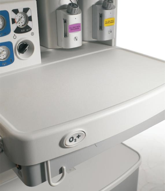
Под столешницей находится переключатель для подачи газовой смеси ACGO. При его активации свежий газ поступает во внешний дыхательный контур ручной вентиляции через специальный выход. Система контролирует давление в дыхательных путях и концентрацию кислорода вместо объема. Также под столешницей есть предметные ящики, и, в зависимости от комплектации, вместо нижних ящиков может стоять встроенный компрессор.
Перейдем к дыхательному контуру. Он крепится к аппарату слева.
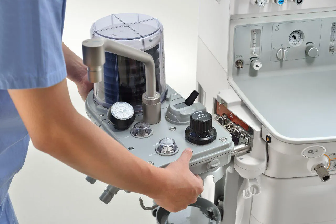
На нем можно увидеть:
- Регулятор предохранительного клапана давления (APL). С его помощью контролируется предельное давление в дыхательном контуре во время искусственной вентиляции в ручном режиме.
- Далее переключатель режима вентиляции — вручную и автоматически
- Подвижный мех или сильфон, защищенный куполом.
- Консоль мешка ручной вентиляции
- Манометр воздуховода
- Обратные клапаны выдоха и вдоха
- Датчик кислорода MOX-2
- Канистра с натронной известью
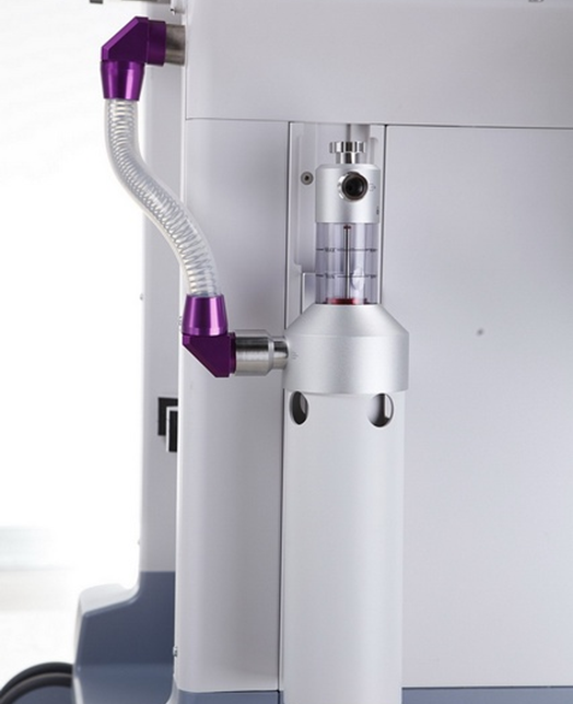
Сбоку аппарата находится система дополнительной подачи кислорода или независимый ротаметр кислорода и пазы для установки дополнительного монитора и слот, куда можно разместить, к примеру, модуль анализатора газов.

Также слева находится место, куда может устанавливаться система передачи и приема отработанных газов AGSS.
На тыльной стороне аппарата расположены розетки, куда можно подключать инфузионные насосы и мониторы пациента. Однако они работают, когда наркозно-дыхательный аппарат сам подключен к сети от сети.
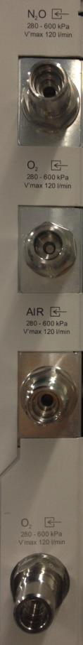
По левому краю расположены входные разъемы для подачи газов. Они промаркированы и каждый имеет свою форму, чтобы не ошибиться при подключения к консоли газов в больнице. Всего здесь разъемов четыре, нижний – для резервной подачи кислорода.
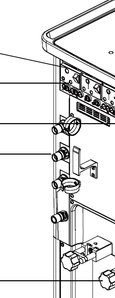
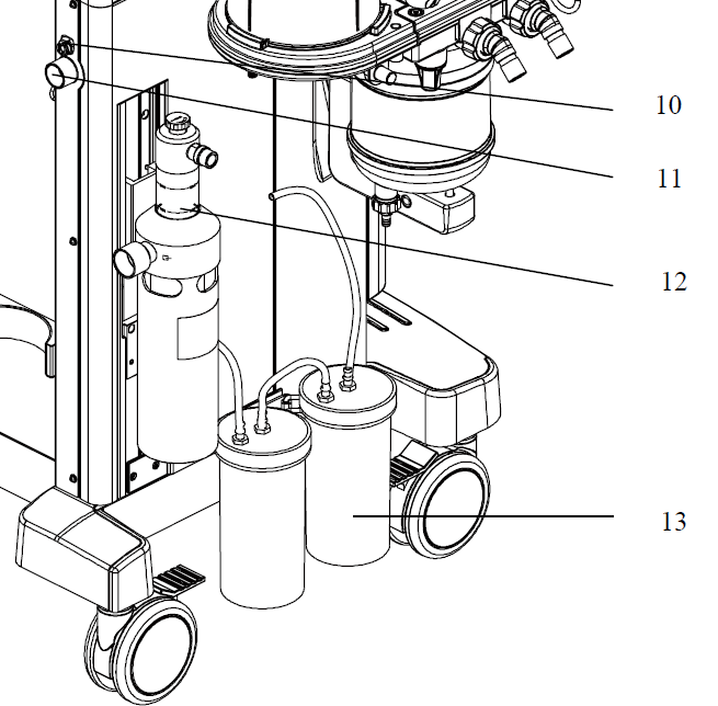
Справа находится вход линии отбора проб отработанного газа (10), а под ним – выходное отверстие (11) для системы устранения отработанных газовых анестетиков – AGSS или СУГА.
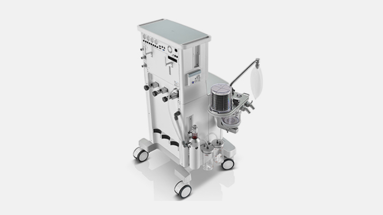
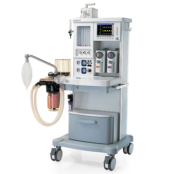
Наркозный аппарат Mindray WATO EX-35
Чтобы узнать актуальные цены, необходимо зарегистрироваться на сайте
Регистрация
Указанная стоимость является информационной, не является публичной офертой, а также не может служить в качестве предложения для обоснования НМЦК для процедур закупки в рамках 44 и 224ФЗ
Наркозный аппарат WATO EX-35
Непревзойденная производительность
Большее удобство в эксплуатации
Новый EX-35 разработан с учетом всех потребностей пользователей. Он предназначен для того, чтобы оптимизировать нелегкий рабочий процесс. Многофункциональная эргономичная наркозная система легко устанавливается и не вызывает сложностей в процессе длительной эксплуатации.
Основной блок
Русский
Стандрат электропитания (Europe)
Стандарт исполнения European (ID)
Стандарт ввода газовых коммуникаций в аппарат NIST-2
Стандарт шлангов высокого давления Ger (Gas hose mode)
Привод от встроенного компрессора
Стандартный вариант
WATO EX-35 базовая стойка, включая:
цветной сенсорный дисплей с диагональю 10.4 дюйма,
анестезиологический вентилятор с дыхательным объёмом(TV) 20-1500 мл в режиме VCV,
каскадные ротаметры с защитой от гипоксии,
рабочая поверхность анестезиолога,
3 или 1 выдвижных ящика(все закрывается на ключ),
1 батарея (90 мин), шланги высокого давления,
полное руководство пользователя,
упаковочный материал
Режим вентиляции с контролем по давлению (PCV)
Состав комплекта
Стандрат электропитания (Europe)
999
Стандарт исполнения European (ID)
999
Стандарт ввода газовых коммуникаций в аппарат NIST-2
999
Стандарт шлангов высокого давления Ger (Gas hose mode)
999
Привод от встроенного компрессора
999
WATO EX-35 базовая стойка, включая:
цветной сенсорный дисплей с диагональю 10.4 дюйма,
анестезиологический вентилятор с дыхательным объёмом(TV) 20-1500 мл в режиме VCV,
каскадные ротаметры с защитой от гипоксии,
рабочая поверхность анестезиолога,
3 или 1 выдвижных ящика(все закрывается на ключ),
1 батарея (90 мин), шланги высокого давления,
полное руководство пользователя,
упаковочный материал
999
Режим вентиляции с контролем по давлению (PCV)
999
(ACGO) Работа по полуоткрытому контуру, независимо от абсорбера
999
Дополнительные розетки
999
Дополнительный ротаметр независимой подачи O2
999
LED подсветка рабочего стола
999
Дополнительная Li-ion батарея (11.1V, 4500mAh)
999
Установка 1-го испарителей
999
Установка 2-х испарителей (selectatec)
999
Установка 2-х испарителей (plug-in)
999
Наборы дыхательных контуров
Набор дыхательного контура, одноразовый, для взрослых, в составе:
— контур пациента (с Y-образным переходником, 1.5 м, трубка 0.5 м, угловой коннектор, прямой коннектор, бактериальный фильтр, дыхательный мешок 3 л. Одноразовая маска, взрослая, размер 5.
999
Набор дыхательного контура, одноразовый, для детей, в составе:
— контур пациента (контур с Y-переходником 1.5 м., трубка 0.5 м, угловой коннектор, прямой коннектор, бактериальный фильтр, дыхательный мешок 1 л), детский — 1 шт.
— маска дыхательная, одноразовая, детская, №2 — 1 шт.
999
Многоразовый дыхательный контур, для взрослых, в составе:
— трубка дыхательная, силикон, для взрослых, 1.5 м — 2 шт.
— дыхательный мешок, силикон, 3 л, 22F — 1 шт.
— маска дыхательная, взрослая, размер 5, силикон, 22 мм — 1 шт.
— Y-образный коннектор — 1 шт.
— L-обрзный коннектор — 1 шт.
999
Многоразовый дыхательный контур, для детей, в составе:
— трубка дыхательная, силикон, для детей, 1.5 м — 2 шт.
— дыхательный мешок, силикон, 1л, 22F — 1 шт.
— маска дыхательная, детская, размер 2, силикон, 22 мм — 1 шт.
— Y-образный коннектор — 1шт.
— L-обрзный коннектор — 1 шт.
999
Набор для изменения концентрации O2 в дыхательной смеси
Набор для изменения концентрации О2 (обязательная позиция, если нет парамагнитного О2 в модуле мультигаза) в дыхательной смеси, включает:
-датчик O2, Medicel MOX-2, 1 шт.
-кабель интерфейсный O2
999
O2 и N2O (стеклянные флоуметры для 20/30/35)
999
O2 и Air (стеклянные флоуметры для 20/30/35)
999
O2 & N2O & Air (стеклянные флоуметры)
999
Шланги высокого давления O2 & N2O
999
Шланги высокого давления O2 & Air
999
Шланги высокого давления O2 & N2O & Air
999
Привод вентилятора Air (сжатый воздух)
999
Привод вентилятора О2 (кислород)
999
Встроенный компрессор
999
Дыхательный контур с держателем мешка без системы bypass (обход абсорбера)
999
Дыхательный контур с держателем мешка с системой bypass (обход абсорбера)
999
Дыхательный контур Pre-Pack (с держателем дыхательного мешка, с системой подогрева, с системой bypass (обход абсорбера))
999
Разъем для встроенных модулей расширения
Слот для модулей — обязательная позиция в случае выбора какого-либо модуля
999
SIMV режим вентиляции (SIMV-VC, SIMV-PC)
999
Вентиляция с поддержкой далением, включая вентиляцию АПНОЭ (PSV, w/ apnea backup)
999
Петли спирометрии PV, FV and PF с рассчётом параметров
999
Приводной газовый поворотный механизм
Автопереключение приводного газа — обязательная позиция в случае выбора компрессорной версии
999
Адаптер для консоли без возможности подключения баллона
999
Резервный разъем для подключения О2
999
V60 Испаритель для Галотана ( Key-Fill), с адатором Key-Fill
999
V60 Испаритель для Галотана(Pour-Fill)
999
V60 Испаритель для Изофлуран ( Key-Fill), с адатором Key-Fill
999
V60 Испаритель для Изофлуран (Pour-Fill)
999
V60 Испаритель для Севофлурана ( Key-Fill), с адатором Key-Fill
999
V60 Испаритель для Севофлурана (Pour-Fill)
999
V60 Испаритель для Севофлурана (Quick Fill)
999
Дополнительное место для испарителя
Дополнительное место для испарителя (3-й испаритель)
999
Система эвакуации газовой смеси (AGSS)
Система пассивной эвакуации газовой смеси, в составе:
-трубка диаметром 32 мм — 1 шт.
-адаптор — 1 шт.
999
Система активной эвакуации газовой смеси (высокий поток и низкое сопротивление) (75-105 л/мин)
999
Система активной эвакуации газовой смеси (низкий поток и высокое сопротивлением)(25-50 л/мин)
999
Аспиратор (Воздушный привод) ВНИМАНИЕ! Данный вид аспиратора доступен только при стандартном варианте аппарата с AIR в качестве приводного газа!
При заказе интегрированного компрессора данная позиция не доступна!
999
Вакуум-аспиратор (вакуумный)
999
Стандарт подключения газов для вакуум-аспиратора
Стандарт подключения газов для вакуум-аспиратора — Германия — обязательная позиция, если выбирается pipeline suction
999
Блок капнометрии в боковом потоке (Sidestream CO2), без расходных материалов
999
Блок капнометрии в основном поток Mainstream CO2, без расходных материалов
999
Комплект расходных материалов для блока капнометрии
Комплект расходных материалов для блока капнометрии (Sidestream CO2), взрослые/дети, включает:
-соединительная трубка с быстроразъёмным адаптером, 1 шт.
-адаптор для подключения в дыхательный контур, 2 шт.,
-влагосборник, взрослые/дети, 2 шт.,
-линия забора пробы газа, взрослые/дети, 2 шт.
999
Комплект расходных материалов для блока капнометрии (Sidestream CO2), новорождённые, включает:
-соединительная трубка с быстроразъёмным адаптером, 1 шт.
-адаптор для подключения в дыхательный контур, 2 шт.,
-влагосборник, новорождённые, 2 шт.,
-линия забора пробы газа, новорождённые, 2 шт.
999
Комплект расходных материалов для блока капнометрии (Mainstream CO2), включает:
-адаптор для подключения в дыхательный контур, взрослые/дети, 1 шт.,
-адаптор для подключения в дыхательный контур, дети/новорождённые, 1 шт.
-датчик Capnostat CO2, 1 шт.,
-крепёж датчика CO2, 1 шт.
999
Блок анализа и измерения концентрации летучих анестетиков, без расходных материалов
999
Блок анализа и измерения концентрации летучих анестетиков/О2, без расходных материалов
999
Набор расходных материалов для блока анализа и измерения концентрации летучих анестетиков
Набор расходных материалов для блока анализа и измерения концентрации летучих анестетиков(обязательная позиция при выборе модуля газоанализа), включает:
— инструкция по применению
— соединительная трубка с быстроразъёмным адаптером — 1 шт.
— адаптер прямой, взрослые/дети — 2 шт.
— адаптер прямой, новорожденные — 2 шт.
— линия забора пробы газа, взрослые/дети — 2 шт.
— линия забора пробы газа, новорождённые — 2 шт.
— влагосборник, взрослые/дети, 2 шт.
— влагосборник, новорождённые, 2 шт.
999
Оставить отзыв
У данного товара нет отзывов. Станьте первым, кто оставил отзыв об этом товаре!
Наркозно-дыхательный аппарат Wato Ex-35 представляет собой устройство для проведения общей анестезии с эргономичным пользовательским интерфейсом и цветным жидкокристаллическим дисплеем высокого разрешения. Может быть использован как для работы со взрослыми пациентами, так и с детьми.
Аппарат отличается сниженным образованием водного конденсата внутри дыхательного контура, что стало возможным благодаря модулю с подогревом. Канистра с поглотителем CO2 оснащена обходным клапаном, за счет которого специалист-анестезиолог сможет с легкостью осуществлять замену натронной извести и не останавливать при этом искусственную вентиляцию.
- Наркозно-дыхательный аппарат с цветным ЖК-дисплеем и пневматическим приводом
- Отображение трех кривых и показателей («MV» (МВ), «Pmean» (Дср), «Paw» (ДДП), «Ppeak» (Дпик), «TVe» (ДОВыд),
- Возможность использования не только базовых, но и дополнительных режимов вентиляции (режим вентиляции с поддержкой давлением (PSV), режим синхронизированной перемежающейся принудительной вентиляции (SIMV) и т.д.)
- Поддержка внешнего мониторинга EtCO2 и АГ
- Электронная система управления
- Использование до 6 режимов ИВЛ
- Возможность автономной работы до 2 часов
- Двойные механические ротаметры для низкопоточной анестезии и точного контроля потока газа
- На экране отображается сообщение, информирующее о правильности установки контейнера
- Минимальный объем 20 мл
Технические характеристики EX-35
|
Общие габариты |
1375х880х620 мм (ВхШхГ) |
|
Вес (без испарителя и баллона) |
<120 кг |
|
Источник питания |
100-240 В |
|
Время автономной работы от аккумулятора |
150 мин. (доя 2 новых полностью заряженных батарей) |
|
Модуль ИВЛ |
Пневматический привод и электронное управление |
|
Режимы вентиляции |
Спонтанное дыхание, ручная вентиляция, SIMV, VCV, PSV, PCV |
|
Дыхательный объем |
20-1500 мл (в режиме VCV) |
|
Диапазон потока при вдохе |
1-100 л/мин |
|
Настройки |
индивидуальные |
|
Поток кислорода |
25-75 л/мин |
|
Емкость для CO² |
1,5 л |
|
Подача газа |
О², О² + О², О² + N²О + воздух, О² + воздух |
|
Крепление для резервных баллонов |
О², О² + О², О² + N²О, О² + воздух |
|
Позиции для испарителей |
2 |
|
Быстросъемная канистра абсорбера |
с функцией обходного шунта для СО2. |
|
Испаритель |
|
|
Крепление испарителя |
Selectatec, с системой Interlock |
|
Мониторинг анестетиков |
опция |
|
Мониторинг EtCO² |
опция |
|
Пневматический вентилятор |
С электронной системой управления |
|
Отслеживаемые параметры |
|
|
Сигналы тревоги |
|
|
Активная система отвода газов (AGSS) |
опция |
|
Просмотр данных |
до 24 часов данных трендов по эпизодам подачи сигналов тревоги. |
|
Динамическая компенсация |
для свежей газовой смеси. |
|
Экран |
Цветной, ЖК |
-
Contents
-
Table of Contents
-
Troubleshooting
-
Bookmarks
Quick Links
WATO EX-65 Anesthesia
Machine
Operator’s Manual
Related Manuals for Mindray WATO EX-65
Summary of Contents for Mindray WATO EX-65
-
Page 1
WATO EX-65 Anesthesia Machine Operator’s Manual… -
Page 3
Revision 1.0 is the initial release of the document. Revision number: Release time: 2009-1 © Copyright 2009 Shenzhen Mindray Bio-Medical Electronics Co., Ltd. All rights reserved. WARNING Federal Law (USA) restricts this device to sale by or on the order of a physician. -
Page 4
WATO are the registered trademarks or trademarks owned by Mindray in China and other countries. All other trademarks that appear in this manual are used only for editorial purposes without the intention of improperly using them. They are the property of their respective owners. -
Page 5
Manufacturer’s Responsibility All information contained in this manual is believed to be correct. Mindray shall not be liable for errors contained herein nor for incidental or consequential damages in connection with the furnishing, performance, or use of this manual. Mindray is responsible for the effects on safety, reliability and performance of this product… -
Page 6
Return Policy In the event that it becomes necessary to return a unit to Mindray, follow the instructions below. Return authorization. Contact the Customer Service Department and obtain a Customer Service Authorization number. This number must appear on the outside of the shipping container. Returned shipments will not be accepted if the number is not clearly visible. -
Page 7
Preface Manual Purpose This manual contains the instructions necessary to operate the product safely and in accordance with its function and intended use. Observance of this manual is a prerequisite for proper product performance and correct operation and ensures patient and operator safety. This manual is based on the maximum configuration and therefore some contents may not apply to your product. -
Page 8
FOR YOUR NOTES… -
Page 9
Contents 1 Safety ……………………..1-1 1.1 Safety Information ………………….1-1 1.1.1 Dangers ………………….1-2 1.1.2 Warnings………………….1-2 1.1.3 Cautions ………………….1-3 1.1.4 Notes ……………………1-4 1.2 Equipment Symbols ………………….1-5 2 The Basics ……………………. 2-1 2.1 System Description ………………….2-1 2.1.1 Intended Use………………….. -
Page 10
4.4.3 Volume Control Ventilation (VCV)…………..4-5 4.4.4 Pressure Control Ventilation (PCV) …………..4-8 4.4.5 Synchronized Intermittent Mandatory Ventilation (SIMV)…….4-11 4.4.6 Pressure Support Ventilation (PSV) …………..4-17 4.5 Start Mechanical Ventilation ………………4-21 4.6 Set the Timer ……………………. 4-22 4.6.1 Start the Timer………………..4-22 4.6.2 Stop the Timer ……………….. -
Page 11
6.6.1 Without O2 Sensor ………………… 6-5 6.6.2 With O2 Sensor ………………..6-7 6.7 Vaporizer Back Pressure Test ………………6-8 6.8 Breathing System Tests ………………..6-9 6.8.1 Bellows Test ………………….. 6-9 6.8.2 Breathing System Leak Test in Mechanical Ventilation Status ……6-10 6.8.3 Breathing System Leak Test in Manual Ventilation Status……..6-11 6.8.4 APL Valve Test ………………..6-11 6.9 Alarm Tests…………………… -
Page 12
8.3.7 Calibrate the Sensor ………………. 8-7 8.4 Use a Microstream CO2 Module ………………8-8 8.4.1 Prepare to Measure CO2 ………………8-8 8.4.2 Make CO2 Settings ……………….. 8-8 8.4.3 Measurement Limitations………………8-11 8.4.4 Scavenge the Sample Gas ……………..8-11 8.4.5 Zero the Sensor ………………..8-12 8.4.6 Calibrate the Sensor ……………… -
Page 13
10.9 Set BIS Smoothing Rate………………..10-7 10.10 Restore Defaults ………………….10-7 10.11 Set BIS Related Waveforms ………………10-8 11 Alarms ……………………..11-1 11.1 Introduction ……………………11-1 11.1.1 Alarm Categories…………………11-1 11.1.2 Alarm Levels ………………..11-2 11.2 Alarm Indicators………………….11-2 11.2.1 Alarm Lamp…………………11-2 11.2.2 Audible Alarm Tones………………11-3 11.2.3 Alarm Message………………..11-3 11.2.4 Flashing Alarm Numeric ……………..11-3 11.2.5 Alarm Status Symbols ………………11-3… -
Page 14
13.2 Install the Breathing Tubes………………13-19 13.3 Install the Manual Bag ………………..13-20 13.4 Install the Vaporizer ………………..13-21 13.4.1 Assemble the Vaporizer …………….13-21 13.4.2 Fill the Vaporizer………………13-25 13.4.3 Drain the Vaporizer ………………13-27 13.5 Install/Replace the Gas Cylinder…………….13-29 13.6 Install Modules…………………. -
Page 15
14.3.7 Sodalime Canister ………………14-19 14.3.8 Breathing Tubes and Y Piece……………. 14-20 14.3.9 Flow Sensor………………..14-20 14.3.10 O2 Sensor ………………..14-21 14.3.11 AGSS Transfer and Receiving System …………14-21 15 Accessories ……………………15-1 A Theory of Operation………………….. A-1 A.1 Pneumatic Circuit System ………………… A-1 A.2 Electrical System Structure ………………. -
Page 16
FOR YOUR NOTES… -
Page 17
Safety 1.1 Safety Information DANGER Indicates an imminent hazard that, if not avoided, will result in death or serious injury. WARNING Indicates a potential hazard or unsafe practice that, if not avoided, could result in death or serious injury. CAUTION Indicates a potential hazard or unsafe practice that, if not avoided, could result in minor personal injury or product/property damage. -
Page 18
1.1.1 Dangers There are no dangers that refer to the product in general. Specific “Danger” statements may be given in the respective sections of this manual. 1.1.2 Warnings WARNING Before putting the system into operation, the operator must verify that the equipment, connecting cables and accessories are in correct working order and operating condition. -
Page 19
WARNING Use appropriate electrodes and place them according to the instructions provided by the manufacturer. The display restores to normal within 10 seconds after defibrillation. 1.1.3 Cautions CAUTION To ensure patient safety, use only parts and accessories specified in this manual. At the end of its service life, the equipment, as well as its accessories, must be disposed of in compliance with the guidelines regulating the disposal of such products. -
Page 20
1.1.4 Notes NOTE Put the equipment in a location where you can easily see the screen and access the operating controls. Keep this manual close to the equipment so that it can be obtained conveniently when needed. The software was developed in compliance with IEC 60601-1-4. The possibility of hazards arising from software errors is minimized. -
Page 21
1.2 Equipment Symbols Attention: Consult accompanying documents (this Dangerous voltage manual) Alternating current Fuse Battery Equipotential Operating state Autoclavable Material description Not autoclavable Power On Power Off Reset Standby Alarm silence key MV&TVe alarm key Normal screen key flush button ACGO On ACGO Off Bag position/ manual… -
Page 22
VGA connector supply connector Table top light AGSS outlet Cylinder PEEP outlet Manufacture date Vaporizer Manufacturer Isolation transformer European community Serial number representative APL valve CAUTION HOT Maximum level of the Lock or unlock as the sodalime canister arrow shows Gas input direction Unlock the lifting device Lock the lifting device… -
Page 23
The Basics 2.1 System Description 2.1.1 Intended Use The anesthesia machine is intended to provide breathing anesthesia for adult, pediatric and infant patients during surgery. The anesthesia machine must only be operated by qualified anesthesia personnel who have received adequate training in its use. WARNING This anesthesia machine is intended for use by qualified anesthesia personnel only or under their guidance. -
Page 24
2.1.3 Components The anesthesia machine consists of a main unit, vaporizer (five optional anesthetic agents: enflurane, isoflurane, sevoflurane, desflurane and halothane), anesthetic ventilator, electronic flowmeter assembly, breathing system etc. The anesthesia machine provides monitoring and displaying of respiratory mechanics (RM) parameters (airway resistance and compliance) and spirometry loops as well. -
Page 25
2.2 Equipment Appearance 2.2.1 Front View ——Display and control panel… -
Page 26
Brake Pipeline pressure gauge (s) Displays the pipeline pressure or the cylinder pressure after relief. Total flowmeter The medium level of flowtube float indicates the current flow of the mixed gas. Flow control (s) When the system switch is set to the ON position: Turn the control counterclockwise to increase the gas flow. -
Page 27
——Breathing system… -
Page 28
sensor connector Inspiration connector Expiration connector Inspiratory check valve Expiratory check valve Bellows housing Sample gas return port (to the AGSS) Manual bag port Bag/mechanical ventilation switch Select the position to use bag for manual ventilation. Select the position to use ventilator for mechanical ventilation. 10. -
Page 29
2.2.2 Rear View ——Power supply… -
Page 30
Cylinder connector (s) Equipotential stud Mains inlet Network connector CIS 12 V power supply connector Speaker Auxiliary O2 supply ACGO (Auxiliary Common Gas Outlet) switch Set the switch to the position to stop mechanical ventilation. Then, fresh gas is sent to the externally connected manual breathing system through the ACGO outlet and the technical alarm of [ACGO On] is triggered. -
Page 31
——Anesthesia information system (CIS) -
Page 32
This rear view is based on the situation that the anesthesia machine is configured with anesthesia information system (CIS). Display Rail Mounting bracket Keyboard CIS main unit A. Reset key : Press to restart the CIS. CIS switch : Press to switch on/off the CIS. USB connector D. -
Page 33
WARNING Connect to the AC mains in compliance with B.3 Power Requirements. Failure to do so may cause damage to the equipment or affect its normal operation. Make sure that the jacket on the electrical outlet is already fixed to avoid power cord off during surgery. -
Page 34
2.3 Batteries NOTE Use batteries at least once every month to extend their life. Charge the batteries before their capacities are worn out. Inspect and replace batteries regularly. Battery life depends on how frequent and how long it is used. For a properly maintained and stored lithium battery, its life expectancy is approximately 3 years. -
Page 35
System Controls and Basic Settings 3.1 Display Control Alarm lamp High level alarms: the lamp quickly flashes red. Medium level alarms: the lamp slowly flashes yellow. Low level alarms: the lamp turns yellow without flashing. Menu shortcut key(s) Push the menu shortcut key to access the corresponding menu. Control knob Push the control knob to select a menu option or confirm your setting. -
Page 36
MV&TVe alarm key In case of manual ventilation mode: Push the key to switch off MV and TVe overrange alarms and apnea alarm. Push the key again to switch on MV and TVe overrange alarms and apnea alarm. In case of mechanical ventilation mode: Push the key to switch off MV and TVe overrange alarms. -
Page 37
3.2 Display Screen This anesthesia machine adopts a high-resolution color TFT LCD to display various parameters and graphs, such as ventilation parameters and pressure/flow/volume waveforms. Depending on how your anesthesia machine is configured, it may display gas module parameters and waveforms, BIS parameters, BIS trend waveform, spirometry loops etc.The following is a standard display screen. -
Page 38
Physiological alarm area Displays physiological alarm messages. Apnea alarm off icon area Displays apnea alarm off icon when apnea alarm is switched off in non-mechanical ventilation mode. Alarm silence icon area Displays alarm silence icon and 120 s countdown time. System time area Displays system time of the anesthesia machine. -
Page 39
Displays information about system operating state. 18 Parameter&graph area Displays the parameters, waveforms, spirometry loops, or electronic flowmeter graphs which the anesthesia ventilator, gas module or BIS module monitors. Different types of screens are displayed based on the actual system configuration or screen layout settings. For details, refer to 5 User Interface and Parameter Monitoring. -
Page 40
3.3.3 Set System Time Select the [Maintenance] shortcut key → [User Maintenance >>] → [Set System Time >>]. Set [Date] and [Time]. Select [Date Format] and toggle between [YYYY-MM-DD], [MM-DD-YYYY] and [DD-MM-YYYY]. Select [Time Format] and toggle between [24 h] and [12 h]. CAUTION Changing date and time will affect the storage of trends and log information. -
Page 41
Select [Ok] from the pop-up menu. After [Ok] is selected, the following settings restore their default values: User screen Ventilator parameters Alarm limits of ventilator-related parameters O2 monitoring source Alarm sound volume and key sound volume Screen brightness Paw display unit 3.3.6.2 Restore the Factory Default Configuration of the Gas Module If the anesthesia machine is configured with CO or AG module, you can directly restore the… -
Page 42
FOR YOUR NOTES… -
Page 43
Operations and Ventilation Setup WARNING Before using this anesthesia machine on the patient, make sure that the system is correctly connected and in good condition, and that all the tests described in 6 Preoperative Test are already completed. In case of test failure, do not use the system. -
Page 44
4.3 Input Fresh Gas 4.3.1 Set O O and Air Inputs Connect the gas supplies correctly and ensure adequate gas pressure. You can control the O O and Air flows in the fresh gas through the O O and Air flow controls. -
Page 45
4.3.2 Set Anesthetic Agent NOTE You do not need to perform this operation if inspiratory anesthetic agent is not used. This anesthesia machine can be mounted with vaporizers corresponding with halothane, enflurane, isoflurane, sevoflurane and desflurane. Only one of the five vaporizers can be opened at a time because the vaporizers are featured with interlock. -
Page 46
4.4 Set Ventilation Mode 4.4.1 Set Manual Ventilation Mode Turn the APL valve control to adjust the pressure in the breathing system within the appropriate range. Set the bag/mechanical ventilation switch to the position. The ventilation mode prompt area displays the icon for manual ventilation mode. Besides, the system prompt message area displays [Manual Vent.]. -
Page 47
NOTE When using the anesthesia machine on the patient, make sure that manual ventilation mode is available. 4.4.2 Make Settings before Starting Mechanical Ventilation Mode Make sure that the system is Standby. Set the appropriate Plimit value in the parameter setup shortcut keys area. Check the ACGO switch to make sure that it is OFF. -
Page 48
To ensure the set tidal volume gas delivery, the ventilator adjusts gas flow based on the measured inspiratory volume, dynamically compensates for the loss of tidal volume arising from breathing system compliance and system leakage and eliminates the effect of fresh gas as well. -
Page 49
NOTE When it is necessary to switch over to VCV mode, confirm the setting of TV first. Otherwise, the system works in the previous ventilation mode. If the setting of TV is not confirmed for 10 s, the screen returns to the previous mode automatically. Before activating a new mechanical ventilation mode, make sure that all related parameters are set appropriately. -
Page 50
NOTE If the parameter value is adjusted outside of the range, the system prompt message area displays [Parameter Settings Outside the Safety Range]. Confirm the adjustment of one parameter before adjusting another parameter. If you want to restore the value before adjustment, you have to reset the parameter value. -
Page 51
4.4.4.2 Waveforms The following figures show the Paw waveform and flow waveform in the PCV mode. Generally, in the PCV mode, the Paw waveform rises sharply during inspiration and stays at the plateau for a relatively long time without peak. The flow waveform declines in the same period. -
Page 52
4.4.4.4 Parameter Setup Shortcut Keys Area in PCV Mode When selection of PCV mode is confirmed, the parameter setup shortcut keys area at the bottom of the screen is automatically switched over to the parameter setup area in this mode. The following figure shows all related parameters to be set in PCV mode. -
Page 53
4.4.4.6 Parameter Range and Default Value in PCV Mode Parameter Range Step Default Pinsp 5 to 60 cmH2O 1 cmH2O 15 cmH2O Rate 4 to 100 BPM 1 BPM 12 BPM 4:1 to 1:8 Plimit 10 to 100 cmH2O 1 cmH2O 30 cmH2O PEEP OFF, 4 to 30 cmH2O… -
Page 54
4.4.5.2 Waveforms SIMV-VC: The following figures show the Paw waveform and flow waveform in the SIMV-VC mode. 【SIMV-VC】+【PSV】 SIMV-PC: The following figures show the Paw waveform and flow waveform in the SIMV-PC mode. 【SIMV-PC】+【PSV】 4-12… -
Page 55
4.4.5.3 Start SIMV Mode You can select [SIMV-VC] or [SIMV-PC] as required. To start SIMV-VC, do as follows: Select the [Vent Mode] shortcut key to open the [Vent Mode Setup] menu. Select [SIMV-VC >>] in the [Vent Mode Setup] menu. Select [Ok] directly in the [SIMV-VC Setup] menu. -
Page 56
4.4.5.4 Parameter Setup Shortcut Keys Area in SIMV Mode When selection of SIMV mode is confirmed, the parameter setup shortcut keys area at the bottom of the screen is automatically switched over to the parameter setup area in this mode. The specific parameters vary depending on SMIV modes, namely, SIMV-VC and SIMV-PC. -
Page 57
NOTE When SIMV mode, either SIMV-VC or SIMV-PC, is selected, pressure support ventilation (PSV) mode is used for triggering outside of the trigger window. Therefore, you also need to set the parameters in PSV mode appropriately, [Psupp], [Finsp] and [PSV Insp Termination Level]. 4.4.5.5 Set Parameters in SIMV Mode Similar to setting the parameters in VCV and PCV modes, you can use the shortcut keys and control knob to set the parameters in SIMV mode. -
Page 58
[Trigger Level] In the SIMV-VC mode, select the [Vent Mode] shortcut key → [SIMV –VC >>] → [Trigger Level]. Or, in the SIMV-PC mode, select the [Vent Mode] shortcut key → [SIMV-PC >>] → [Trigger Level]. Or, in the PSV mode, select the [Vent Mode] shortcut key →… -
Page 59
4.4.5.6 Parameter Range and Default Value in SIMV Mode Parameter Range Step Default SIMV mode 20 to 100 ml: 5 ml SIMV-VC 20 to 1500 ml 100 to 300 ml: 10 ml 300 to 1500 ml: 25 ml Pinsp 5 to 60 cmH2O 1 cmH2O 15 cmH2O SIMV-PC… -
Page 60
When PSV mode is applied alone, the PCV backup mode is available. If within the preset time (Backup Mode Active), no spontaneous breathing occurs or spontaneous breathing is not strong enough to reach Trigger Level, the PCV backup mode is activated automatically when the time for Backup Mode Active is up to enable mechanical ventilation forcibly. -
Page 61
4.4.6.4 Parameter Setup Shortcut Keys Area in PSV Mode When selection of PSV mode is confirmed, the parameter setup shortcut keys area at the bottom of the screen is automatically switched over to the parameter setup area in this mode. The following figure shows all related parameters to be set in PSV mode. -
Page 62
In PSV mode, you also need to set: [Trigger Level] Select the [Vent Mode] shortcut key → [PSV >>] → [Trigger Level]. Select [Pressure] or [Flow] for trigger type. Turn the control knob to set [Trigger Level] to the appropriate value. Push the control knob to confirm the setting. -
Page 63
4.4.6.6 Parameter Range and Default Value in PSV Mode Parameter Range Step Default Ventilation mode Pinsp 5 to 60 cmH2O 1 cmH2O 15 cmH2O (backup ventilation mode) Rate 4 to 60 BPM 1 BPM 10 BPM 4 to 100 BPM 1 BPM 12 BPM Finsp… -
Page 64
4.6 Set the Timer 4.6.1 Start the Timer To start the timer, select the timer setup shortcut key and select [Start]. NOTE During timing, if you select [Start] from the [Timer Setup] menu again, timing continues normally instead of restart. 4.6.2 Stop the Timer To stop the timer, select the timer setup shortcut key and then [Stop]. -
Page 65
4.7 Stop Mechanical Ventilation To stop mechanical ventilation, do as follows: Make sure that the breathing system is set up and the APL valve is set properly before stopping mechanical ventilation. The APL valve adjusts the breathing system pressure limit during manual ventilation. Its scale shows approximate pressure. -
Page 66
FOR YOUR NOTES 4-24… -
Page 67
User Interface and Parameter Monitoring 5.1 Screen Layout Depending on module and functional configurations, user screens differ in parameter&graph area and parameter setup shortcut keys area. User screens fall into four categories: Standby screen Normal screen Big numerics screen Measured values screen The standby screen is switched over through the Standby key on the panel. -
Page 68
5.1.1 Standby Screen When the anesthesia machine is not in use for a short period of time, entering standby status can help save power and extend service life of the machine. The anesthesia machine enters standby status automatically after start-up. To enter standby status, you can also push the key in operating mode and then select [Ok] from the pop-up menu. -
Page 69
5.1.2 Normal Screen On the normal screen, parameter/graph area and waveform area are divided. Parameter/graph area Waveform area The structure of these two areas varies depending on the configurations. 5.1.2.1 Parameter&graph Area This area displays parameters and spirometry loops or electronic flowmeters as well. The parameter&graph combinations displayed vary depending on the configurations. -
Page 70
5.1.3 Special Screen Special screen includes big numerics screen and measured values screen. The screen layout Parameter&graph Big numerics/measured area values sharing area 5.1.3.1 Parameter&graph Area This area may display: CO2 parameters AG parameters BIS parameters Electronic flowmeters For details, refer to the respective sections of this chapter. 5.1.3.2 Big Numerics/Measured Values Sharing Area This area displays either big numerics or measured values. -
Page 71
When screen layout is set to measured values screen, this area displays Paw waveform and ventilation parameters as shown below. 5.2 Screen Setup To set the desired screen style, Select the [Screens] shortcut key and select [Screens]. You can toggle between [Normal Screen], [Big Numerics] and [Measured Values]. 5.3 Parameter Monitoring 5.3.1 O2 Concentration Monitoring If your anesthesia machine is configured with an O2 sensor, select [Maintenance] →… -
Page 72
5.3.1.2 Set FiO2 Alarm Limits Select the [Alarm Setup] shortcut key and select [Ventilator >>]. Set FiO2 high and low alarm limits in the [Ventilator Alarm Limits] menu. When the measured FiO2 exceeds the alarm limit, an alarm is generated. Select to exit the current menu. -
Page 73
5.3.1.4 Display O2 Waveform If the AG module which your anesthesia machine is configured with incorporates an O2 module, an O2 waveform is displayed as shown below. 5.3.2 Anesthetic Agent (AA) Concentration Monitoring If your anesthesia machine is configured with AG module, you can monitor FiAA and EtAA by setting up the AG module. -
Page 74
NOTE As required by the relevant international rules and regulations, anesthetic agent concentration monitoring needs to be performed when the anesthesia machine is used on the patient. If your anesthesia machine is not configured with such monitoring function, use a qualified monitor for anesthetic agent concentration monitoring. -
Page 75
5.3.3.3 Other Settings For details, refer to 8CO2 Monitoring and 9AG and O2 Concentration Monitoring. NOTE As required by the relevant international rules and regulations, CO2 concentration monitoring needs to be performed when the anesthesia machine is used on the patient. -
Page 76
Select to exit the current menu. Set waveform scale. The Paw waveform scale is automatically adjusted based on the set Plimit. You can set the Paw waveform scale appropriately by setting Plimit. 5.3.4.4 Set Paw Unit Select the [Maintenance] shortcut key and select [User Maintenance >>]. Select [Paw Unit] and toggle between [cmH2O], [hPa] and [mbar]. -
Page 77
If your anesthesia machine is not configured with CO2 or AG module, tidal volume and breath rate related parameters are displayed as shown below. [MV]: Minute ventilation [TVe]: Expired tidal volume [Rate]: Breath rate [FiO2]: Fraction of inspired oxygen 5.3.5.2 Display Flow Waveform 5.3.5.3 Set Flow Waveform Select the flow waveform area to access the [Flow Waveform Setup] menu. -
Page 78
5.3.5.4 Set MV and TVe Alarm Limits Select the [Alarm Setup] shortcut key and select [Ventilator >>]. Set MV high and low alarm limits in the [Ventilator Alarm Limits] menu. Set TVe high and low alarm limits as required. Select to exit the current menu. -
Page 79
5.3.7 Volume Monitoring 5.3.7.1 Display Volume Waveform 5.3.7.2 Set Volume Waveform Select the waveform area to access the waveform setup menu. Select [Waveform] and select [Volume]. Select [Sweep] and toggle between [6.25 mm/s] and [12.5 mm/s]. The greater the value is, the faster the waveform sweeps. -
Page 80
5.3.9 BIS Monitoring 5.3.9.1 Display BIS Parameters If your anesthesia machine is configured with BIS module, on the normal screen, BIS related parameters are displayed as shown below. [BIS]: Bispectral index [SQI]: Signal quality index [EMG]: Electromyograph If your anesthesia machine is configured with BIS module, on the special screen, BIS related parameters are displayed as shown below. -
Page 81
5.3.9.2 Display BIS EEG Waveform If your anesthesia machine is configured with BIS module, BIS EEG and BIS Trend waveforms are displayed as shown below. BIS EEG waveform: BIS Trend waveform: 5.3.9.3 Set BIS EEG Waveform Select the waveform area to access the waveform setup menu. Select [Waveform] and select [BIS EEG]. -
Page 82
5.4 Display Electronic Flowmeter Gas flow can be displayed either in a standard-resolution mode or high-resolution mode. These two resolution modes vary in scale and accuracy. Switchover between the standard-resolution mode and the high-resolution mode can be performed manually based on gas flow. The default is high-resolution mode. The scale range of the standard-resolution mode is 0 to 10 L/min and that of the high-resolution mode 0 to 6 L/min. -
Page 83
Preoperative Test 6.1 Preoperative Test Schedules 6.1.1 Test Intervals Perform the preoperative tests listed below at these events: Before each patient. When required after a maintenance or service procedure. The following table indicates when a test must be done. Test Item Test Intervals Every day before the first patient Pipeline tests… -
Page 84
6.2 Inspect the System NOTE Make sure that the breathing system is correctly connected and not damaged. The top shelf weight limit is 30 kg. Make sure that: The anesthesia machine is undamaged. All components are correctly attached. The breathing system is correctly connected, and the breathing tubes are undamaged. The vaporizers are locked in position and contain sufficient agent. -
Page 85
Make sure that the AC mains indicator is illuminated and the battery indicator stops flashing and continues illuminated. Meanwhile, the prompt message [Battery in Use] disappears. Set the system switch to the position. 6.4 Pipeline Tests NOTE Do not leave gas cylinder valves open if the pipeline supply is in use. Cylinder supplies could be depleted, leaving an insufficient reserve supply in case of pipeline failure. -
Page 86
6.4.2 N2O Pipeline Test Connect an O supply before doing the N O pipeline test. For details, refer to 6.4.1O2 Pipeline Test NOTE When doing the N O pipeline test, connect O supply first to enable N O flow control. Different from O pipeline supply, when N O supply is disconnected, no alarms… -
Page 87
6.5.2 O2 Cylinder High Pressure Leak Test Set the system switch to the position and stop O pipeline supply. Turn off the O flowmeter. Open the O cylinder valve. Record the current cylinder pressure. Close the O cylinder valve. Record the cylinder pressure after one minute. If the cylinder pressure decreases more than 5000 kPa (725 psi), there is a leak. -
Page 88
NOTE After doing the cylinder tests, close all cylinder valves if cylinder supplies are not used. Turn the flow controls slowly. Do not turn further when the flow indicated on the flowmeter is outside of the range to avoid damaging the control valve. When the flow control is turned to the minimum, the reading indicated on the flowmeter should be zero. -
Page 89
NOTE When O supply is disconnected, alarms for [O2 Supply Failure] and [Drive Gas Pressure Low] occur as O pressure decreases. Set the system switch to the position. 6.6.2 With O2 Sensor Do as described in 6.9.2 Test the O2 Concentration Monitoring and Alarms before testing. To do the flow control system tests: Connect the pipeline supplies or slowly open the cylinder valves. -
Page 90
Make sure that the N O flow decreases. The measured O concentration must be ≥21% through the full range. Disconnect the O pipeline supply or close the O cylinder valve. Make sure that: O and O flows stop. The O flow stops last. -
Page 91
NOTE Do not perform test on the vaporizer when the concentration control is between “OFF” and the first graduation above “0” (zero) as the amount of anesthetic drug outputted is very small within this range. 6.8 Breathing System Tests WARNING Objects in the breathing system can stop gas flow to the patient. -
Page 92
6.8.2 Breathing System Leak Test in Mechanical Ventilation Status NOTE Breathing system leak test must be performed when the system is in standby status. Before doing the breathing system leak test, make sure that the breathing system is correctly connected and the breathing tubes not damaged. Make sure that the system is Standby. -
Page 93
6.8.3 Breathing System Leak Test in Manual Ventilation Status Make sure that the system is Standby. If not, press the key and select [Ok] from the pop-up menu to enter standby status. Set the bag/mechanical ventilation switch to the bag position. Connect the manual bag to the manual bag port. -
Page 94
6.9 Alarm Tests The anesthesia machine performs a self test after started. The alarm lamp flashes yellow and red once in turn and then a beep is given. Then the display shows the start-up screen and enters the standby screen after 30 seconds. This means that audio and visual alarm indicators begin to work normally. -
Page 95
6.9.2 Test the O2 Concentration Monitoring and Alarms NOTE This test is not required if no O sensor is configured. Set the bag/mechanical ventilation switch to the bag position. Remove the O sensor. After two to three minutes, make sure that the sensor measures approximately 21% O in room air. -
Page 96
6.9.4 Test the Apnea Alarm Connect the manual bag to the manual bag port Set the bag/mechanical ventilation switch to the bag position. Turn the APL valve control to set the APL valve to the minimum position. 4. Inflate the manual bag to make sure that a complete breathing cycle occurs. Stop inflating the manual bag and wait for more than 20 seconds to make sure that the apnea alarm occurs. -
Page 97
6.9.7 Test the Low Paw Alarm Set the bag/mechanical ventilation switch to the mechanical position. Select the [Alarm Setup] shortcut key and then [Ventilator >>]. Set the Paw low alarm limit to 2 cmH Disconnect the manual bag from the Y piece patient connection. Wait for 20 seconds. -
Page 98
WARNING Before connecting a patient, flush the anesthesia machine with 5 L/min of O for at least one minute. This removes unwanted mixtures and by-products from the system. 6.11 Inspect the AGSS Assemble the AGSS as described in 13.10.2Assemble the AGSS and then turn on the waste gas disposal system. -
Page 99
User Maintenance 7.1 Repair Policy WARNING Only use lubricants approved for anesthesia or O equipment. Do not use lubricants that contain oil or grease. They burn or explode in high O concentrations. Obey infection control and safety procedures. Used equipment may contain blood and body fluids. -
Page 100
7.2 Maintenance Schedule NOTE These schedules are the minimum frequency based on typical usage of 2000 hours per year. You should service the equipment more frequently if you use it more than the typical yearly usage. Minimum Maintenance frequency Clean the external surfaces. Daily 21%O2 calibration (O sensor in breathing system). -
Page 101
7.3 Breathing System Maintenance When cleaning the breathing system, replace any parts that are visibly cracked, chipped, distorted or worn. For details, refer to 13 Installations and Connections and 14 Cleaning and Disinfection. 7.4 Flow Sensor Calibration NOTE Do not perform calibration while the unit is connected to a patient. During calibration, do not operate the pneumatic parts. -
Page 102
Plug the Y piece into the leak test plug to close the breathing system. Remove the water collection cup. For details, refer to 14.2.11 Water Collection Cup. Make sure that the system is Standby. If not, press the key and then select [Ok] from the pop-up menu to enter standby status. -
Page 103
NOTE In case of calibration failure, check for sensor malfunctioning alarm and then troubleshoot it if there is. If it still fails or great measurement error occurs after calibration, select [Defaults] to restore the factory default calibration values. If the measurement error is still great, replace the flow sensor and repeat the above operation. -
Page 104
To calibrate at 21% O , do as follows: Make sure that the system is Standby. If not, press the key and then select [Ok] from the pop-up menu to enter standby status. Select the [Maintenance] shortcut key → [O2 Sensor Cal. >>] → [21% O2 Cal. >>] to open the [O2 21% Cal.] menu. -
Page 105
Position the patient O sensor connector to the air. Turn on ACGO. Turn on the O inlet and adjust the flow above 8 L/min. Turn off other gas supplies. After two to three minutes, select [Start] from the menu to start to calibrate at 100% O The screen prompts [Calibrating]. -
Page 106
7.6.2 Clear Water Build-up The water built up inside the flow sensor will result in inaccurate measured value of tidal volume and trigger the [TV Comp Disabled] alarm. If there is water built up inside the flow sensor, remove the sensor and clear the water. Then reinstall the sensor for use. -
Page 107
Use a screwdriver to adjust the zeroing screw, letting the pressure gauge pointer go to zero. Zeroing point Set the bag/mechanical ventilation switch to the mechanical position. Plug the Y piece into the leak test plug to close the breathing system. Push the O2 flush button repeatedly to sweep the pointer across the pressure gauge. -
Page 108
7.8 AGSS Transfer Tube Maintenance Check the tube of the AGSS transfer system. Replace it if it is damaged. 7-10… -
Page 109
CO2 Monitoring 8.1 Introduction monitoring is a continuous, non-invasive technique for determining the concentration of in the patient’ airway by measuring the absorption of infrared (IR) light of specific wavelengths. The CO has its own absorption characteristic and the amount of light passing the gas probe depends on the concentration of the measured CO When a specific band of IR light is passed through respiratory gas samples, some of IR light will be absorbed by the CO… -
Page 110
8.2 Identify CO2 Module Sidestream CO module, microstream CO module and mainstream CO module are shown below from left to right. setup key Measure/standby key Gas outlet watertrap fixer Sampling tube connector sensor connector If you measure CO using AG module, refer to 9 AG and O2 Concentration Monitoring… -
Page 111
8.3 Use a Sidestream CO2 Module NOTE This section is only applicable to the anesthesia machine configured with sidestream CO2 module. 8.3.1 Prepare to Measure CO2 Attach the watertrap to the watertrap fixer and then connect the CO2 components as shown below. -
Page 112
CAUTION The watertrap collects water drops condensed in the sampling line and therefore prevents them from entering the module. If the collected water reaches a certain amount, you should drain it to avoid airway blockage. The watertrap has a filter preventing bacterium, vapor and patient secretions from entering the module. -
Page 113
8.3.2.4 Set Gas Compensations WARNING Make sure that the appropriate compensations are used. Inappropriate compensations may cause inaccurate measured values and result in misdiagnosis. Access the [Gas Module Setup >>] menu. Set the following compensations based on the actual conditions: [O2 Comp] [N2O Comp] [Des Comp]… -
Page 114
8.3.2.7 Set CO2 Waveform Select the waveform area to access the waveform setup menu. Select [Waveform] and select [CO2]. Select [Sweep] and set waveform sweep speed to an appropriate value. The greater the value is, the faster the waveform sweeps, the wider the waveform is. Select [Scale] and toggle between: [40], [60] and [80] if the unit is mmHg;… -
Page 115
8.3.5 Scavenge the Sample Gas Metal chip Exhaust tube To scavenge the sample gas to the waste gas disposal system, depress the metal chip and then plug the exhaust tube to the ports marked (sample gas return to the AGSS) on the anesthesia machine as shown in the above picture. -
Page 116
8.4 Use a Microstream CO2 Module NOTE This section is only applicable to the anesthesia machine configured with microstream CO2 module. 8.4.1 Prepare to Measure CO2 Plug the sampling tube into the sampling tube connector and then connect the CO2 components as shown below. -
Page 117
8.4.2.1 Set Working Mode The default working mode of the CO2 module is [Measure] when the anesthesia machine is turned on for the first time. If the current CO2 module is Standby, you must push the key or select the [User Setup] shortcut key → [Gas Module Setup >>] → [Working Mode] →… -
Page 118
8.4.2.4 Set Maximum Hold In the CO2 parameter area, EtCO2 and FiCO2 values are refreshed in real-time. To set EtCO2 and FiCO2: Access the [Gas Module Setup >>] menu. Select [Max Hold] and select: [Single Breath]: EtCO and FiCO are calculated based on each breath. [10 s], [20 s] and [30 s]: EtCO and FiCO2 refer to the highest and the lowest CO2 values measured respectively within the configured time period (10 s, 20 s or 30 s). -
Page 119
8.4.3 Measurement Limitations Measurement accuracy may degrade due to: Leakage or internal leakage of the sample gas. Mechanical shock Cyclic pressure which is greater than 10 kPa (100 cmH2O) Other interference source (if available) 8.4.4 Scavenge the Sample Gas Metal chip Exhaust tube To scavenge the sample gas to the waste gas disposal system, depress the metal chip and then plug the exhaust tube to the ports marked… -
Page 120
8.4.5 Zero the Sensor Zeroing the sensor aims to eliminate the effect of baseline drift on the readings during the measurement so as to ensure measurement accuracy. For microstream CO2 module, a zero calibration is carried out automatically when necessary. You can also start a manual zero calibration when deemed necessary. -
Page 121
8.5 Use a Mainstream CO2 Module NOTE This section is only applicable to the anesthesia machine configured with mainstream CO2 module. 8.5.1 Prepare to Measure CO2 Connect the sensor to the CO2 module. By default, the mainstream CO2 module is in measure mode. The [CO2 Warmup] message appears on the screen when the CO2 module is plugged in. -
Page 122
8.5.2 Make CO2 Settings By selecting the [User Setup] shortcut key and then [Gas Module Setup >>], you can make CO2 settings described below. 8.5.2.1 Set Working Mode The default working mode of the CO2 module is [Measure] when the anesthesia machine is turned on for the first time. -
Page 123
[AG Comp]: enters the concentration of anesthetic gas (if there is) in the ventilation gas mixture to compensate for the effect of anesthetic gas upon the readings. The total of the concentrations of O2 compensation and AG compensation cannot be greater than 100%. -
Page 124
8.5.3 Measurement Limitations Measurement accuracy may degrade due to: Leakage or internal leakage of the sample gas. Mechanical shock Cyclic pressure which is greater than 10 kPa (100 cmH2O) Other interference source (if available) 8.5.4 Zero the Sensor Zeroing the sensor aims to eliminate the effect of baseline drift on the readings during the measurement so as to ensure measurement accuracy. -
Page 125
AG and O2 Concentration Monitoring 9.1 Introduction The anaesthetic gas (AG) module measures the patient’s anesthetic and respiratory gases, and incorporates the features of the O module and BIS module as well. The AG (anesthesia gas) module determines the concentrations of certain gases using the infrared (IR) light absorption measurement. -
Page 126
9.2 Understand MAC Values Minimum alveolar concentration (hereinafter referred to as MAC) is a basic index indicating the depth of inhaled anesthesia. The ISO 21647 defines MAC as follows: alveolar concentration of an inhaled anesthetic agent that, in the absence of other anesthetic agents and at equilibrium, prevents 50% of subjects from moving in response to a standard surgical stimulus. -
Page 127
9.3 Identify AG Modules There are two types of AG modules available. M-type, which cannot identify anesthesia gas automatically. A-type, which can identify anesthesia gas automatically. AG setup key Measure/standby key Indicator Gas outlet AG watertrap fixer BIS sensor connector For details about BIS, refer to 10 BIS Monitoring. -
Page 128
Connect the exhaust tube to the gas outlet on the module to scavenge the sample gas to the waste gas disposal system. AG module Airway adapter Exhaust tube Gas sampling tube Connect to the patient By default, the AG module is in measure mode. The message [AG Startup] appears on the screen when the AG module is plugged in. -
Page 129
9.5 Make AG Settings By selecting the [User Setup] shortcut key and then [Gas Module Setup >>], you can make AG settings described below. 9.5.1 Set Anesthetic Agent As M-type AG module cannot identify the type of anesthetic agent automatically, you need to set [Agent] to select the correct type of anesthetic agent before venting the anesthetic agent. -
Page 130
When [Working Mode] is set to [Measure], the message [AG Startup] appears on the screen. After start-up is finished, the message [AG Warmup] is displayed. The AG module is in ISO accuracy mode .After warm-up is finished, the .AG module enters full accuracy mode. 9.5.5 Set CO2 Unit In the [Gas Module Setup >>] menu, select [CO2 Unit] and toggle between [mmHg], [%], and [kPa]. -
Page 131
The A-type AG module can identify anesthetic agent automatically. When one anesthetic agent decreases below the threshold value and another anesthetic agent plays the dominant role, the anesthesia machine can identify such exchange automatically and displays the name and data of the dominant anesthetic agent. 9.7 Measurement Limitations Measurement accuracy may degrade due to: Leakage or internal leakage of the sample gas. -
Page 132
9.9 Scavenge the Sample Gas Metal chip Exhaust tube To scavenge the sample gas to the waste gas disposal system, depress the metal chip and then plug the exhaust tube to the ports marked (sample gas return to the AGSS) on the anesthesia machine as shown in the above picture. -
Page 133
BIS Monitoring 10.1 Introduction Bispectral index (BIS) monitoring is for use on adult and pediatric patients within a hospital or medial facility providing patient care to monitor the state of the brain by data acquisition of EEG signals. The BIS, a processed EEG variable, may be used as an aid in monitoring the effects of certain anesthetic agents. -
Page 134
10.3 Safety Information For patients with neurological disorders, patients taking psychoactive medication, and children under one year of age, BIS values should be interpreted cautiously. WARNING The conductive parts of sensors and connectors should not come into contact with other conductive parts, including earth. To reduce the hazard of burns in the high-frequency surgical neutral electrode connection, the BIS sensor should not be located between the surgical site and the electro-surgical unit return electrode. -
Page 135
10.4 Understand BIS Parameters BIS monitoring provides the following parameters for display as shown below. Non-Extend sensor Extend sensor Bispectral Index (BIS) The BIS numeric reflects the patient’s level of consciousness. Typically, it ranges from 40 to 60 for a patient under general anesthesia during surgery. BIS numeric Description The patient is widely awake. -
Page 136
Spectral Edge Frequency (SEF) The SEF is the frequency below which 95% of the total power is measured. Total Power (TP) TP numeric which only monitors the state of the brain indicates the power in the frequency band 0.5-30Hz. The useful range is 40-100db. Burst Count (BC) A burst means a period (at least 0.5 second) of EEG activity followed and preceded by inactivity. -
Page 137
Connect the BIS sensor to the patient cable. As soon as a valid sensor is detected, the impedances of all electrodes are measured automatically and the impedance value for each electrode is displayed in the sensor check window. CAUTION Do not attach the BISx model to the patient’s skin for a long time. Otherwise, the BISx heats while on the patient and may cause discomfort. -
Page 138
10.7 Cyclic Impedance Check This measures the exact impedance of each individual electrode. It causes a disturbed EEG wave, and a prompt message is displayed on the screen. The cyclic impedance check is automatically initiated when a sensor is connected. To manually start a cyclic impedance check manually, you can either: Select [Cyc. -
Page 139
Measure electrode impedance Time of the most recent impedance check Start/stop cyclic impedance checks Show sensor information The measured electrode-to-skin impedance and electrode status are displayed above each electrode: Status Description Action [Lead off] Electrode falls off and has no skin Reconnect electrode, or check the contact. -
Page 140
10.11 Set BIS Related Waveforms To set BIS EEG waveform: Select the waveform area, open the corresponding menu. Select [BIS EEG] for [Waveform]. Select [Sweep] and set waveform sweep speed to an appropriate value. The greater the value is set to, the faster the waveform sweeps, the wider the waveform is. Select [Scale] and set waveform scale to an appropriate value. -
Page 141
Alarms 11.1 Introduction Alarms, triggered by a vital sign that appears abnormal or by technical problems of the anesthesia machine, are indicated to the user by visual and audible alarm indications. NOTE When the anesthesia machine is started, the system detects whether alarm lamp and audible alarm tones function normally. -
Page 142
11.1.2 Alarm Levels By severity, the anesthesia machine’s alarms fall into three categories: high level alarms, medium level alarms and low level alarms. High level alarms Indicates that the patient is in a life threatening situation and an emergency treatment is demanded. -
Page 143
11.2.2 Audible Alarm Tones The anesthesia machine uses different alarm tone patterns to match the alarm level: High level alarms: triple+double+triple+double beep. Medium level alarms: triple beep. Low level alarms: single beep. 11.2.3 Alarm Message When an alarm occurs, an alarm message will appear in the technical or physiological alarm area. -
Page 144
11.3 Set Alarm Volume Select the [User Setup] shortcut key. Select [Screen and Audio Setup >>] and then [Alarm Sound Volume] to select an appropriate value ranging from 1 to 10. The value 1 is for the lowest and 10 for the loudest. -
Page 145
11.4.3 Set AG Alarm Limits Select the [Alarm Setup] shortcut key and then [Gas Module >>]. Set [High Limit] and [Low Limit] respectively for each parameter. Select to exit the current menu. 11.4.4 Set BIS Alarm Limits Select the [Alarm Setup] shortcut key and then [Gas Module >>]. Set [High Limit] and [Low Limit] respectively for each parameter. -
Page 146
WARNING Take care to set [CPB] to [ON] because some physiological alarms are not triggered under this setting. These disabled physiological alarms include: apnea alarm, Volume Apnea>2 min, Paw too low, TVe too high, TVe too low, MV too high, MV too low, Rate too high, Rate too low, EtCO2 too low, FiCO2 too low, EtN2O too low, FiN2O too low, EtHal too low, FiHal too low, EtEnf too low, FiEnf too low, EtIso too low, FiIso too low, EtSev too low, FiSev too low, EtDes too low and FiDes too low. -
Page 147
11.9 Alarm Silence 11.9.1 Set 120 s Alarm Silence Pressing the 120 s alarm silence key will set the system to alarm silenced status. Sound alarm will be disabled. Besides, the alarm silence symbol and 120 s countdown time will appear in the upper right corner of the screen. -
Page 148
FOR YOUR NOTES 11-8… -
Page 149
Trend and Logbook 12.1 Trend Graph A trend graph is used to review the trend of parameter values within a specific time period. The trend is reflected through a curve. Every point on the curve corresponds to the parameter value at a specific time point. You can review TVe, MV, Ppeak, FiO EtCO , Plat, PEEP, Pmean, Rate and BIS data within a maximum of 24-hour operating time. -
Page 150
12.2 Trend Table A trend table is used to recall the patient’s physiological parameter data at a specific time point. The parameter data are reflected through a table. You can recall TVe, MV, Ppeak, FiO EtC0 , Plat, PEEP, Pmean, Rate and BIS data at the selected resolution within a maximum of 24-hour operating time. -
Page 151
12.3 Alarm Logbook For alarm logbook, the system provides up to 100 events, which are stored in chronological order. When a new event occurs after 100 events are already stored, the new event overwrites the earliest one. To access the Alarm Logbook window, select the [Maintenance] shortcut key → [Trend and Logbook >>] →… -
Page 152
FOR YOUR NOTES 12-4… -
Page 153
Installations and Connections WARNING Continuous use of desiccated sodalime may endanger patient safety. Adequate precautions should be taken to ensure that the sodalime in the sodalime canister does not become desiccated. Turn off all gases when finished using the system. When electrosurgical equipment is used, keep the electrosurgical leads away from the breathing system, the O sensor and other parts of the anesthesia machine. -
Page 154
13.1.1 Breathing System Diagrams 13-2… -
Page 155
Bellows housing Expiration connector Bag arm Inspiration connector Bag/mechanical ventilation switch Water collection cup APL valve Locking hook Inspiratory check valve Drive gas connector Expiratory check valve Guide pin hole Plug for O sensor (O sensor optional) Locking catch retainer Rotary handle Pressure sampling connector(s) Sodalime canister… -
Page 156
NOTE The heating module does not work when the anesthesia machine is battery powered. Do not overbear the bag arm, such as depressing it forcibly or hanging heavy objects onto it. When the difference between the reading on the airway pressure gauge and the Paw value displayed is great, please contact us. -
Page 157
Push the breathing system into the circuit adapter with force to let the breathing system connected to the adapter seamlessly. Set the locking catches on the circuit adapter to the position and make sure that the breathing system is safely locked. WARNING Set the locking catches to the position after the breathing system is installed… -
Page 158
NOTE If it is hard to push the breathing system into or out of the circuit adapter, you need to apply some lubricant (M6F-020003— : “Dupont Krytox high-performance fluorine lubricating grease”)to the seal on the pneumatic connector to reduce friction. 13.1.4 Install the Bag Arm Align the bag arm with the connector on the breathing system. -
Page 159
Turn the locking nut clockwise to tighten the bag arm. 13.1.5 Install the Bellows Attach the bottom ring of the folding bag to the bellows base on the breathing system and make sure that the bag is tightly connected to the base. Folding bag Bellows base Seal… -
Page 160
Align the bellows housing bayonet tabs with the slots on the breathing system and then lower the bellows housing. Make sure that the housing is depressing the seal evenly. Hold the bellows housing tightly and turn it clockwise until it stops. Make sure that the side of the housing marked with scale is facing the operator. -
Page 161
13.1.6 Install the Flow sensor Make sure that the direction of arrow on the flow sensor is same to that on the breathing system and the side with silkscreen is facing upward. Insert the flow sensor horizontally. Align the inspiration/expiration connectors and their locking nuts with the flow sensor connectors. -
Page 162
Tighten the locking nuts clockwise. WARNING Tighten the locking nuts when installing the flow sensor. Failure to do so may result in invalid measurement. Exert care when moving the anesthesia machine to prevent the flow sensor from getting damaged. The end of inspiration/expiration connectors which connects the breathing tube shall be kept downward to prevent condensed water from entering the breathing system. -
Page 163
Align the threads of the O sensor with the O sensor connector marked on the breathing system and turn the sensor clockwise to tighten it. Insert one end of the O sensor cable into the sensor jack 13-11… -
Page 164
Insert the other end of the O sensor cable into the O sensor connector marked the circuit adapter. 13.1.8 Install the Sodalime Canister WARNING Obey applicable safety precautions. Do not use the sodalime canister with chloroform or trichloroethylene. Disposable sodalime canister is a sealed unit which should not be opened or refilled. -
Page 165
WARNING Inspect sodalime color during the surgery or at the end of a case. During non-use, sodalime may go back to the original color. Refer to the sodalime labelling for more information about color changes. Adequate precautions should be taken to ensure that the sodalime in the sodalime canister does not become desiccated. -
Page 166
13.1.8.1 Assemble the Sodalime Canister The following figures show the components of a sodalime canister: A. Sodalime Canister support Sodalime canister D. Canister handle Canister support buckle Press the buckle as shown in the figure to remove the canister support. 13-14… -
Page 167
Before installing the sodalime canister, inspect the canister mouth, canister support and seal for sodalime particles. If there is, please clear it. Canister seal Canister support Canister mouth Align the sodalime canister with the mounting slot. Canister mounting slot Push the sodalime canister into the mounting slot. 13-15… -
Page 168
Turn the rotary handle clockwise for 90 degrees. Let the rotary handle fall to lock the sodalime canister. 13-16… -
Page 169
CAUTION Remember to do a breathing system leak test after reinstalling the sodalime canister. 13.1.8.2 Change the Sodalime NOTE A gradual color change of the sodalime in the canister indicates absorption of carbon dioxide. The color change of the sodalime is only a rough indicator. Use carbon dioxide monitoring to determine when to change the sodalime. -
Page 170
Pour new sodalime into the sodalime canister. When pouring, prevent the sodalime from falling on the venthole of the canister support, which may increase airway resistance. Install the canister support into the canister. Depress the canister support buckle to lock the canister. -
Page 171
NOTE The sodalime which is poured in cannot exceed the level marked on the sodalime canister. 13.2 Install the Breathing Tubes NOTE When installing the breathing tube, hold the tube connector at both ends of the tube to prevent damage of the tube. Do not reuse the filter to prevent cross-contamination. -
Page 172
Connect the filter to the Y piece. 13.3 Install the Manual Bag Connect the manual bag to the manual bag port on the breathing system. The anesthesia machine is configured with bag arm: The anesthesia machine is not configured with bag arm: 13-20… -
Page 173
13.4 Install the Vaporizer WARNING If the vaporizer is incompatible with the anesthesia machine, the performance of the anesthetic agent in the vaporizer will be degraded. Use the vaporizer matching the anesthesia machine. NOTE For details about how to install and use the vaporizer, refer to the Vaporizer Instructions for Use. -
Page 174
Push and turn the locking lever A clockwise to lock the vaporizer in position. Make sure that the top of the vaporizer is horizontal. If not, remove the vaporizer and reinstall it. In case of reinstalling the vaporizer, try to lift each vaporizer straight up off the manifold rather than pulling forward. -
Page 175
With a Desflurane vaporizer: Make sure that the vaporizer is connected to an electrical outlet. Plug in the electrical input cable. Push the adapter into the mounting box. 13-23… -
Page 176
Lift the hand-pull block, rotate it counterclockwise for 270 degrees and then release it to fix the adapter onto the mounting box. Connect the power cord at the other end of the adapter to the power source. Try to turn on more than one vaporizer at the same time. NOTE For details about how to use the Desflurane vaporizer, refer to Instructions for Use of Desflurane vaporizer. -
Page 177
13.4.2 Fill the Vaporizer WARNING Make sure that the correct anesthetic agent is used. The vaporizer is designed with the specific anesthetic agent named on it and further indicated by color coded labelling. The concentration of the anesthetic agent actually output will vary if the vaporizer is filled with the wrong agent. -
Page 178
13.4.2.2 Quik-Fil System Check that the vaporizer concentration control is in the off (“0”) position. Remove the protective cap from the anesthetic agent bottle filler, checking that the bottle and filler mechanism are not damaged. Remove the vaporizer filler block cap and insert the bottle nozzle into the filler block. Rotate the bottle to align the bottle filler keys with the slots in the filler block. -
Page 179
13.4.3 Drain the Vaporizer WARNING Do not reuse the agent drained from the vaporizer. Treat as a hazardous chemical. 13.4.3.1 Pour Fill System Check that the vaporizer concentration control A is in the 0 (zero) position. Unscrew the filler cap B. Place a bottle marked with the drug name on the vaporizer under the drain tube in the base of the filler block. -
Page 180
13.4.3.2 Quik-Fil System NOTE To avoid spillage, check that the bottle to be used for draining has sufficient capacity for the volume of liquid to be drained. WARNING The filler cap must be refitted before using the vaporizer. Remove the protective cap from an empty bottle. Insert the bottle nozzle into the drain funnel. -
Page 181
13.5 Install/Replace the Gas Cylinder To install/change a gas cylinder, do as follows: Turn the handle of the cylinder valve clockwise. Close the cylinder valve on the cylinder to be replaced Handle of the cylinder valve Turn the tee handle counterclockwise. Tee handle Fully loosen the tee handle to open the yoke gate. -
Page 182
Remove the used cylinder and the used gasket. Gasket Point the cylinder outlet away from all items that can be damaged by a release of high pressure gas. Quickly open and close the cylinder valve. This removes dirt from the cylinder outlet. Install a new gasket. -
Page 183
13.6 Install Modules Push the module into the slot with force until you hear a click, indicating the module is installed in place. To remove the module, lift the wrench at the bottom of the module and then drag the module outward. After inserting the module, make sure that the indicator on the module is lit up. -
Page 184
13.6.3 Install the BIS Module 13.7 Pneumatic Connectors This anesthesia machine provides two types of connectors —pipeline connectors (for O O and AIR) and cylinder connectors (for O and N For the pipeline connectors, four types of configuration are available: and N and AIR O and AIR… -
Page 185
WARNING The anesthesia machine stops gas delivery when the supply gas pressure is lower than 200 kPa. 13.7.1 Connect the Pipeline Gas Supplies The anesthesia machine provides three (O2, N O and AIR) pipeline supply connectors which are connected to three tubes of different colors and cannot be exchanged. Connect the pipeline gas supplies as follows: Check that the seal at the tube connector is in good condition before connecting the gas supply tube. -
Page 186
13.8 CIS Connector The anesthesia machine can be connected to an anesthesia information system (CIS), which is to be installed, serviced and updated by Mindray authorized or approved personnel. For details, refer to the Instructions for Use accompanying the CIS. -
Page 187
13.10 AGSS Transfer and Receiving System 13.10.1 Components Top cover The AGSS outlet on the top cover is connected with the AGSS active scavenging tube. Filter screen Sight glass Float “MIN” mark AGSS inlet Pressure compensation opening 30 mm male conical connector Hook 10. -
Page 188
13.10.2 Assemble the AGSS Mount the AGSS bracket onto the lower left decorative plate of the anesthesia machine. Install M4 socket head screws and spring washers Install fixed pins Mount the AGSS system already equipped with hook onto the AGSS bracket. Connect the 30 mm male conical connector of the transfer tube to the gas inlet of the receiving system. -
Page 189
Connect the 30 mm female conical connector of the transfer tube to the AGSS waste gas outlet on the anesthesia machine. NOTE Remove the AGSS transfer and receiving system from the main unit when transporting or moving the anesthesia machine. 13.10.3 Waste Gas Disposal System The AGSS transfer and receiving system is of high flow and low vacuum type, which is in compliance with ISO 8835-3:1997. -
Page 190
WARNING This AGSS transfer and receiving system cannot be used with flammable anesthetic agent. Gas inside the AGSS may overflow when the gas flow exceeds 100 mL/min if the tube between the waste gas disposal system and the AGSS is occluded, the extract flow of the waste gas flow system is insufficient, or the waste gas disposal system malfunctions. -
Page 191
Cleaning and Disinfection WARNING Obey applicable safety precautions. Read the material safety data sheet for each cleaning agent. Read the operation and service manual for all disinfection equipment. Wear gloves and safety glasses. A damaged O sensor can leak and cause burns (contains potassium hydroxide). -
Page 192
NOTE Do not soak synthetic rubber parts for more than 15 minutes. Swelling or faster aging can occur. Only autoclave parts marked 134ºC. Cleaning solutions must have a pH of 7.0 to 10.5. 14.1 Clean and Disinfect the Anesthesia Machine Housing Clean the surface of the anesthesia machine housing with a damp cloth soaked in mild detergent (such as 70% ethanol). -
Page 193
14.2.1 O2 Sensor Remove one end of the O sensor cable from the connector on the anesthesia machine. Unplug the other end of the cable from the O sensor. Turn the O sensor counterclockwise to take it out. 14-3… -
Page 194
14.2.2 Manual Bag Remove the manual bag from the manual bag port on the breathing system as shown below. The anesthesia machine is configured with bag arm: The anesthesia machine is not configured with bag arm: 14-4… -
Page 195
14.2.3 Breathing Tubes NOTE When disassembling the breathing tube, hold the tube connectors at both ends of the tube to prevent damage to the tube. Do not reuse the filter. Follow local regulations regarding disposal of hospital waste when the filter is discarded. Remove the filter from the Y piece. -
Page 196
14.2.4 Airway Pressure Gauge Pull off the airway pressure gauge as shown below. 14.2.5 Bag Arm Loosen the locking nut counterclockwise. Remove the bag arm from the breathing system. 14-6… -
Page 197
14.2.6 Bellows Assembly Turn the bellows housing counterclockwise. Lift off and remove the housing. Remove the folding bag from the bellows base. 14-7… -
Page 198
14.2.7 Flow Sensor Turn the locking nuts counterclockwise. Pull out the inspiration/expiration connectors and their locking nuts. Pull out the flow sensors horizontally. 14-8… -
Page 199
14.2.8 Expiratory Check Valve Assembly Turn the check valve cover counterclockwise to remove it. Pull out the check valve. 14.2.9 Inspiratory Check Valve Assembly For details about how to disassemble the inspiratory check valve assembly, refer to 14.2.8 Expiratory Check Valve Assembly. 14-9… -
Page 200
14.2.10 Sodalime Canister Hold and pull up the rotary handle for 90 degrees. Turn the rotary handle for 90 degrees counterclockwise. 14-10… -
Page 201
Pull off the sodalime canister from the lifting device. To reassemble the canister, refer to 13.1.8 Install the Sodalime Canister. WARNING Sodalime is a caustic substance and is a strong irritant to eyes, skin and respiratory system. Affected parts should be flushed with water. If irritation continues after flushed by water, seek medical assistance immediately. -
Page 202
14.2.12 Breathing system Hold the breathing system with one hand. Pull up the locking catches on the circuit adapter with the other hand to unlock it. Remove the breathing system from the circuit adapter with both hands. 14-12… -
Page 203
NOTE If it is hard to push the breathing system into or out of the circuit adapter, you need to apply some lubricant to the seal on the pneumatic connector to reduce friction. 14.2.13 AGSS Transfer and Receiving System 14.2.13.1 Filter Turn the nut on the AGSS active scavenging tube counterclockwise to disconnect the tube from the top cover. -
Page 204
Take out the nut, fixed plate and filter screen by turn. Fixed plate Filter screen 14.2.13.2 Float Disconnect the waste gas disposal system from the top cover. Rotate the top cover counterclockwise to separate it from the sight glass. Take out the sight glass. Sight glass Take out the float. -
Page 205
14.2.13.3 Spoiler After taking out the float, remove the spoiler. Spoiler 14.3 Clean&Disinfect and Re-install the Breathing System Parts marked are autoclavable. Metal and glass parts can be steam autoclaved. Maximum recommended temperature is 134ºC. By using autoclave to solidify bacterioprotein rapidly, quick and reliable sterilization can be achieved. -
Page 206
All parts of the breathing system can be cleaned and disinfected. The cleaning and disinfection methods are different for different parts. You need to select the appropriate method to clean and disinfect the parts based on the actual situations to avoid cross-contamination. This table is our recommended cleaning and disinfection methods for all parts of the breathing system. -
Page 207
14.3.1 Breathing system Refer to methods recommended in the table of 14.3 Clean&Disinfect and Re-install the Breathing System to clean and disinfect the breathing system. Make sure that the breathing system is fully dry before installing it with reference to 13.1.3Install the Breathing system in the reverse order. -
Page 208
14.3.4 Breathing Mask Refer to the methods recommended in the table of 14.3 Clean&Disinfect and Re-install the Breathing System to clean and disinfect the breathing mask. 14.3.5 Inspiratory and Expiratory Check Valves Assembly Refer to the methods recommended in the table of 14.3 Clean&Disinfect and Re-install the Breathing System to clean and disinfect the inspiratory and expiratory check valves assembly. -
Page 209
NOTE Disassemble the bellows assembly before cleaning it. If not, it will take a very long time to dry. If autoclaving is necessary, assemble the bellows assembly first. Turn over the bellows assembly to autoclave it. Refer to the methods recommended in the table of 14.3 Clean&Disinfect and Re-install the Breathing System to clean and disinfect the bellows assembly. -
Page 210
14.3.8 Breathing Tubes and Y Piece NOTE When installing or cleaning the breathing tube, hold the tube connectors at both ends of the tube to prevent damage to the tube. Refer to the methods recommended in the table of 14.3 Clean&Disinfect and Re-install the Breathing System to clean and disinfect the breathing tubes and Y piece. -
Page 211
WARNING The end of inspiration/expiration connectors which connects the breathing tube shall be kept downward to prevent condensed water from entering the breathing system. 14.3.10 O2 Sensor WARNING Do not put both of the breathing system and the O sensor in liquid or autoclave them. -
Page 212
WARNING Do not autoclave the AGSS. NOTE Make sure that the float is fully dry before installing it onto the AGSS after cleaning. Even a very amount of liquid may cause the float to stick to the guide bar or sight glass, resulting in inaccurate flow indication. Immerse, disinfect and clean the AGSS by strictly following the concentration specified in the Instructions for Use provided by the disinfectant supplier. -
Page 213
Accessories WARNING Use only accessories specified in this chapter. Using other accessories may cause incorrect measured valued or equipment damage. Disposable accessories can not be reused. Reuse may degrade performance or cause cross-contamination. Check the accessories and their packages for damage. Do not use them if any sign of damage is detected. -
Page 214
Mask Mask.Sil-Flex Silicone,Size 1,Infant Large,15mm OD M6Q-150003— Mask.Sil-Flex Silicone,Size 2,Child,22mm ID M6Q-150004— Mask.Economy Silicone,Size 3,Child Large,22mm ID M6Q-150005— Mask.Economy Silicone,Size 4,Adult,22mm ID M6Q-150006— Mask.Economy Silicone,Size 5,Adult Large,22mm ID M6Q-150007— Aircushion Mask,Size 2 w/valve,Infant Large,15mm M6Q-150009— Aircushion Mask,Size 3 w/valve,Child,22mm M6Q-150010— Aircushion Mask,Size 4 w/valve,Child Large,22mm M6Q-150011— Aircushion Mask,Size 5 w/valve,Adult,22mm… -
Page 215
Sidestream CO module DRYLINE Watertrap (Adult/pediatric, Reusable) 9200-10-10530 Sampling Line, Adult 2.5m (Adult/pediatric, Disposable) 9200-10-10533 DRYLINE Airway Adapter (Straight, Adult/pediatric, Disposable) 9000-10-07486 Microstream CO module Sampling line, XS04620, adult/pediatric, disposable 0010-10-42560 Sampling line, XS04624, adult/pediatric, high humidity, disposable 0010-10-42561 Sampling line, 007768, adult/pediatric, long, disposable 0010-10-42563 Sampling line, 007737, adult/pediatric, long, high humidity, disposable 0010-10-42564… -
Page 216
Power cord Power cord, European style, 5m 0000-10-11215 Power cord, British style, 5m 009-000093-00 Power cord, American style, 5m 009-000094-00 Battery Lithium battery/DK-MR-644 M05-010001-06 BIS module BIS sensor, adult 0010-10-42672 BIS sensor, pediatric 0010-10-42673 BIS patient cable, adult/pediatric 6800-30-50761 AGSS AGSS transfer tube assembly 0611-30-67693 (tube connecting the anesthesia machine to the AGSS main unit. -
Page 217
Theory of Operation A.1 Pneumatic Circuit System A.1.1 Pneumatic Circuit Diagram… -
Page 218
A.1.2 Parts List P-Line Flow indicator cylinder Double-vaporizer manifold Air P-Line Check valve O P-Line Pressure relief valve (38 kPa) O cylinder ACGO selector switch Regulator (0.4 MPa) Inspiratory check valve Safety valve (0.7 MPa) absorber Filter BYPASS stop valve Regulator (0.2 MPa) Expiratory check valve 10 Inspiratory flow control valve… -
Page 219
A.1.3 Description Gas supplies The anesthesia machine has pipeline and cylinder gas supplies available. Pipeline gas supplies, O O and Air, go into the system through pipeline connectors 1, 3 and 4 respectively. The pipeline pressure ranges between 280 and 600 kPa. Cylinder gas supplies, and N O, go into the system through cylinder connectors 2 and 5 respectively. -
Page 220
the microprocessor-controlled valve 10 creates the preset inspiratory flow and expiratory valve 17 closes. The drive gas goes into the bellows 45 and depresses the bag inside the bellows to move downward. This forces the gas inside the bag to go through the sodalime canister 34 to enter the patient lung until the end of inspiration. -
Page 221
A.2.2 Parts List AC mains filter Main board Electrical outlet Infrared backplane Fuse 1 Electronic flowmeter board Isolation transformer board Heater AC conversion board Table top light board Fuse 2 Ship-shaped switch Power supply conversion board of the Power board anesthesia information system Battery assembly Anesthesia information system… -
Page 222
FOR YOUR NOTES… -
Page 223
Product Specifications The anesthesia machine is integrated with pressure restriction device, expiratory volume monitor, breathing system with alarm system, pressure measurement device, anesthetic ventilation system, AGSS transfer and receiving system, anesthetic gas delivery device, anesthetic ventilator, O2 monitor, CO2 monitor and AG monitor, where: The pressure restriction device, expiratory volume monitor and breathing system with alarm system comply with GB 9706.29 and IEC 60601-2-13. -
Page 224
B.2 Environmental Specifications Main unit Item Temperature (ºC) Related humidity Barometric pressure (kPa) (non-condensing) Operating 10 to 40 15 to 95% 70 to 106 Transport storage –20 to +55 10 to 95% 50 to 106 AG module Item Temperature (ºC) Related humidity Barometric pressure (kPa) -
Page 225
Internal battery Number of batteries One or two Battery type Lithium-ion battery Rated voltage 11.1 VDC Capacity 4400 mAh (a single battery) 5 min at least (powered by new fully-charged batteries after the Time to shutdown first low-power alarm) 60 min in case of one battery or 120 min in case of two batteries Operating time (powered by new fully-charged batteries at 25℃… -
Page 226
Size 10.4″ Resolution 800 x 600 pixels Brightness Adjustable LED indication One (yellow and red. When high and medium level alarms occur Alarm lamp simultaneously, it flashes red only) AC power LED One (green; lit when connected to the AC power source). One (green;… -
Page 227
O2 flush 35 to 75 L/min Flowmeter Air range: 0 to 10 L/min O2 range: 0 to 10 L/min N2O range: 0 to 10 L/min Electronic flowmeters Accuracy: < ±10% of the indicated value (under 20 ℃ and 101.3 kPa, for flow between 10% of full scale or 300 mL/min (whichever is greater) and full scale) Type: Rotameter… -
Page 228
Volume Approximately 6 ml Interface and connector Male 22 mm conical connector incorporating a coaxial female 15 mm Expiration end conical connector Male 22 mm conical connector incorporating a coaxial female 15 mm Inspiration end conical connector Male 22 mm conical connector incorporating a coaxial female 15 mm Bag end conical connector Airway pressure gauge… -
Page 229
Expiratory resistance Mechanical Manual Flow (L/min) Inspiratory resistance Mechanical Manual Flow (L/min) B.7 Ventilator Specifications Ventilator parameter setting range Parameter Setting range Step Operating mode Plimit 10 to 100 cmH 1 cmH All modes Pinsp PEEP+5 to 60 cmH 1 cmH2O PCV, PSV, SIMV-PC Psupp… -
Page 230
Rate 4 to 100 BPM 1 BPM VCV, PCV, PSV I:E 4:1 to 1:8 VCV, PCV, PSV TIP:TI OFF, 5 to 60% Finsp 20 to 85 L/min 1 L/min PSV、SIMV-VC、 SIMV-PC Trigger Window 5 to 90% SIMV-PC, SIMV-VC SIMV Rate 4 to 60 BPM 1 BPM SIMV-VC,SIMV-PC… -
Page 231
B.8 Ventilator Accuracy Control and monitoring accuracy <75 ml: ±15 ml; Volume control ≥75 ml: ±20 ml or ±10% of the set value, whichever is greater. Pinsp: ±3.0 cmH O or ±8% of the set value, whichever is greater. Pressure control Plimit: ±4.0 cmH O or ±10% of the set value, whichever is greater. -
Page 232
B.9 Anesthetic vaporizer Anesthetic vaporizer (for details, refer to the vaporizer Instructions for Use) Penlon Sigma Delta or Sigma Alpha anesthetic vaporizers. Five Type types of vaporizers with anesthetic agents halothane, enflurane, isoflurane, sevoflurane, desflurane are available. Vaporizer position Single or double vaporizer positions (optional) Selectatec®, with interlocking function (Selectatec®… -
Page 233
B.11 O2 Sensor Specifications sensor Output 9-13 mV at 210 hPa O2 Range 0 to 1500 hPa O2 100% O2 signal deviation 100±1% Resolution 1 hPa O2 Expected working life 1.5 x 10⁶ % for measurement (20°C) 0.8 x 10⁶ % for measurement (40°C) Response time (21% air to 100% O2) <… -
Page 234
Theory of Operation O2 sensor can monitor the patient’s FiO2. O2 sensor is of the self-powered, diffusion limited, metal-air battery type comprising an anode, electrolyte, diffusion barrier and air cathode as shown below: Air supply Solid membrane Diffusion barrier Cathode Electrolyte Load resistor Anode… -
Page 235
Humidity Effects Under conditions where liquid condensation may occur, care is needed to ensure the gas access holes do not become blocked. If liquids form in the region of the gas access hole, the flow of gas to the sensor will be restricted. With gas access restricted, a low signal will result. If a sensor shows signs of being affected by condensation, normal operation may be restored by drying the sensor with a soft tissue. -
Page 236
B.12 CO2 Module Specifications Mainstream CO2 Module Specifications Mainstream CO module Measurement mode Mainstream Measurement range Accuracy 0 to 40 mmHg ±2 mmHg Measurement range and 41 to 70 mmHg ±5% of the reading accuracy 71 to 100 mmHg ±8% of the reading 101 to 150 mmHg ±10% of the reading 0 to 69 mmHg… -
Page 237
Microstream CO module Flow 50 mL/min (accuracy: -7.5 mL/min +15 mL/min) 30 s (typical), reaching ±5% of the accuracy in stable state within 3 Initialization time minutes Rise time <190 ms(10 to 90%) Delay time 2.7 s (typical) System total 2.9 s (typical), including rise time and delay time response time Calibrate the module for the first time after it has worked for 1200 hours… -
Page 238
Sidestream CO module <4 s@70 mL/min Measured by using neonatal watertrap and 2.5 m neonatal sampling line. <5.5 s@100 mL/min <7 s@70 mL/min Measured by using adult watertrap and 2.5 m adult sampling line. Pump rate 70 mL/min and 100 mL/min optional Pump rate accuracy ±15﹪… -
Page 239
B.13 AG Module Specifications AG Module Type Three-slot module (BIS and O modules are optional) Standard ISO 11196 Measurement mode Sidestream ISO accuracy mode <45 s Warm-up time Full accuracy mode <10 min Pump rate: 120/150/200 mL/min optional Pump rate Accuracy: ±10 mL/min or ±10%, whichever is greater CO2, O2 (optional), N2O, and any of the five anesthetic agents: Des, Iso,… -
Page 240
±0.4 5 to 10 ±0.6 10 to 15 ±1 15 to 18 Not specified >18 ±0.15 0 to 1 ±0.2 1 to 5 ±0.4 5 to 8 Not specified >8 ±0.15 Enf, Iso, Hal 0 to 1 ±0.2 1 to 5 Not specified >5 Rise time*… -
Page 241
AG alarm limits Range Step Unit EtCO High Limit (low limit + 2) to 76 mmHg EtCO Low Limit 0 to (high limit – 2) FiCO2 High Limit (low limit + 2) to 76 FiCO2 Low Limit 0 to (high limit – 2) O High Limit (low limit + 2) to 100 O Low Limit… -
Page 242
Effect of interfering gas on AG measured value ) Quantitive effect(% Concentration (%) Agent AG1) 0.13) Nitrogen ≤78% Xenon <100% Helium <50% Ethanol <0.1% Acetone <1% Methane <1% Methoxyflurane Unspecified Unspecified Unspecified Unspecified 1) Multiple agent interference on CO2, N2O and O2 is typically the same as single agent interference. -
Page 243
B.14 BIS Module Specifications BIS Module Type Single-slot module Standard IEC60601-2-26 Measurement method Bispectral index, power spectrum analysis Measured parameters BIS: 0 to 100 Calculated parameters Impedance range 0 to 999 kΩ Sweep speed 6.25, 12.5, 25 or 50 mm/s Input impedance >50 MΩ… -
Page 244
FOR YOUR NOTES B-22… -
Page 245
This anesthesia machine meets the requirements of IEC 60601-1-2:2001+A1:2004. NOTE Using accessories, sensors and cables other than those specified may result in increased electromagnetic emission or decreased electromagnetic immunity of the equipment. The anesthesia machine or its components should not be used adjacent to or stacked with other equipment. -
Page 246
Guidance and Declaration — Electromagnetic Emissions The anesthesia machine is suitable for use in the specified electromagnetic environment. The customer or the user of the anesthesia machine should assure that it is used in such an environment as described below. Emissions test Compliance Electromagnetic environment — guidance Radio frequency (RF) -
Page 247
<5 % U (>95 % dip Voltage dips, <5 % U (>95 % dip Mains power quality should in U ) for 0.5 cycle short in U ) for 0.5 cycle be that of a typical interruptions and commercial or hospital 40 % U (60 % dip in voltage variations… -
Page 248
⎡ ⎤ Radiated RF 10V/m 10 V/m 80 MHz~800 MHz ⎢ ⎣ ⎥ ⎦ (E1) IEC61000-4-3 80MHz~ ⎡ ⎤ 2.5GHz 800 MHz~2.5 GHz ⎢ ⎣ ⎥ ⎦ Where, is the maximum output power rating of the transmitter in watts (W) according to the transmitter manufacturer and is the recommended separation distance in meters (m). -
Page 249
Recommended Separation Distance between Portable/Mobile RF Communications Equipment and the Anesthesia Machine The anesthesia machine is suitable for use in an electromagnetic environment in which radiated RF disturbance are controlled. The customer or the user of the anesthesia machine can help prevent electromagnetic interference by maintaining a minimum distance between portable/mobile RF communications equipment (transmitters) and the anesthesia machine as recommended below, according to the maximum output power of the communications equipment. -
Page 250
FOR YOUR NOTES… -
Page 251
Alarm Messages This chapter lists only the most important physiological and technical alarm messages. Some messages appearing on your ventilator display may not be included. Note that in this chapter: Column L stands for the default alarm level: H for high, M for medium and L for low. “●” indicates that the alarm level is user-adjustable. -
Page 252
TVe Below In the VCV mode, TVe is lower than the minimum tidal Control Range volume setting for five continuous breathing cycles. Check the patient’s condition, pneumatic circuit connection and flow sensor. MV Too High MV is higher than the high alarm limit setting. If ventilation mode is switched or settings for ventilator parameters are changed, this alarm is disabled temporarily within nine breathing cycles or one minute (whichever is less) after… -
Page 253
EtCO2 Too High The measured value has risen above the high alarm limit or ● fallen below the low alarm limit. Check the patient’s module EtCO2 Too Low ● physiological condition. Make sure that patient type and FiCO2 Too High ●… -
Page 254
D.2 Technical Alarm Messages Source Alarm message Cause and action RT Clock Need There is no button cell available in the system, or the System Reset battery is empty. Replace with a new button cell. RT Clock Not Exist RT chip malfunction. Contact your service personnel. Low Battery The battery voltage is too low. -
Page 255
Device Fault, Equipment malfunction. Mechanical ventilation and Ventilator Ventilate Manually monitoring did not work. Use manual ventilation mode to help the patient breathe and restart the anesthesia machine. If the alarm cancels, restart mechanical ventilation. Ventilator CPU error. Unreliable monitoring. Use Hardware Error 01 manual ventilation mode to help the patient breathe Contact your… -
Page 256
Drive Gas Pressure The pressure of drive gas is low. Unreliable monitoring. Use manual ventilation mode to help the patient breathe Contact your service personnel. O2 Supply Failure The O pressure is low. If Air supply is connected, use manual ventilation mode to help the patient breathe. Make sure that O supply with sufficient pressure is connected. -
Page 257
Sensor failed. Or, great drift occurred to the flow sensor and inspiratory valve. Use manual ventilation mode to help the patient breathe. Calibrate the flow sensor and inspiratory valve. Calibrate PEEP Last calibration of the Paw sensor and PEEP valve failed. Valve Or, great drift occurred to the Paw sensor and PEEP valve. -
Page 258
TVe>TVi TVe is greater than TVi for consecutive six cycles. Check the flow sensor. TV Delivery Too TVi is greater than the set value by 20% for consecutive High six times. Check the fresh gas flow. Insp Reverse Flow M There is gas flowing through the inspiratory flow sensor during expiration for consecutive six cycles. -
Page 259
Flowmeter Flash selftest error Hardware Error 06 Flowmeter Watchdog selftest error Hardware Error 07 Flowmeter Cal. Air, O and N O data empty Data Error 01 Flowmeter Cal. Air, O and N O data error Data Error 02 Flowmeter Comm XX module failed to Error communicate with the main… -
Page 260
AG Watertrap Type The watertrap of the AG module is of wrong type. Wrong Replace with a correct watertrap. AG Data Limit AG module malfunction Error AG Accuracy Error The measured value is outside of the measurement accuracy range. FiO2 ALM LMT The FiO2 alarm limit settings are outside of the range. -
Page 261
MAC < 3 MAC value was less than 3. Mixed Agent and More than more anesthetic agents were detected ant the MAC >= 3 MAC value was not less than 3. EtCO2 ALM LMT The EtCO alarm limit settings are outside of the range. module FiCO2 ALM LMT The FiCO2 alarm limit settings are outside of the range. -
Page 262
CO2 Hardware Errors occurred to: Error 1. External A/D sampling 2.5 V 2. 12V power supply voltage 3. Internal A/D sampling 2.5 V 4. Pump. 5. 3-way valve. CO2 Sampleline An error or occlusion occurred to the sampling line. Occluded CO2 Zero Failed Deviation of gain input signal is too great to be adjusted. -
Page 263
BIS Overrange The measured value is outside of the measurement range. Contact your service personnel. SQI Overrange SR Overrange BIS High Imped. Check sensor connections. Re-connect the sensor. BIS Sensor Off BIS DSC Error BIS DSC signal reception error. Check the DSC. BIS DSC Malf BIS DSC switched off due to malfunction. -
Page 264
FOR YOUR NOTES D-14… -
Page 265
Symbols and Abbreviations E.1 Symbols ampere ampere hour Breaths per minute centigrade ºC cubic centimeter centimeter decibel fahrenheit ℉ gram hour hertz inch inch kilo kilogram kilopascal litre pound meter microampere hour mbar mbar milligrams minute milliliter millimeters mmHg millimeters of mercury millisecond millivolt… -
Page 266
milliwatt nanometer part per million second volt volt ampere Ω µA microampere µV microvolt watt minus percent per;divide;or ~ power plus + = equal to less than < > greater than ≤ less than or equal to ≥ greater than or equal to ±… -
Page 267
E.2 Abbreviations Anaesthetic agent AGSS Anesthesia Gas Scavenging System ACGO Auxiliary Common Gas Outlet BTPS body temperature and pressure,Saturated Compliance (Cdyn) Airway Pressure Limit Desflurane Enflurane EtCO2 End-tidal carbon dioxide Finsp Flow of inspiration FiCO2 Fraction of inspired carbon dioxide Fractional concentration of O in inspired gas Flow… -
Page 268
Rate Breath rate Sevoflurane SIMV Synchronized intermittent mandatory ventilation SIMV-PC Synchronized intermittent mandatory ventilation — Pressure control SIMV-VC Synchronized intermittent mandatory ventilation — Volume control SIMV Rate Frequency of SIMV Tinsp Time of inspiration TIP:TI Percentage of inspiratory plateau time in inspiratory time Tidal volume Volume control ventilation Volume… -
Page 269
Factory Defaults This chapter lists the most important factory default settings which are not user-adjustable. When necessary, you can restore the factory default settings. F.1 CO2 Module module alarm limits Factory default settings Alarm Level EtCO2 High Limit (mmHg) EtCO2 Low Limit (mmHg) FiCO2 High Limit (mmHg) F.1.1 Mainstream CO2 Module Setup… -
Page 270
F.1.3 Sidestream CO2 Module CO2 Setup Factory default settings Paw Unit mmHg Working Mode Measure Pump Rate High N2O Comp (%) O2 Comp (%) Des Comp (%) Humidity Comp F.2 AG Module AG Setup Factory default settings Agent Pump Rate O2 Comp Working Mode Measure… -
Page 271
EtEnf Low Limit (%) FiEnf High Limit (%) FiEnf Low Limit (%) EtIso High Limit (%) EtIso Low Limit (%) FiIso High Limit (%) FiIso Low Limit (%) EtSev High Limit (%) EtSev Low Limit (%) FiSev High Limit (%) FiSev Low Limit (%) EtDes High Limit (%) EtDes Low Limit (%) -
Page 272
F.4 Ventilator Ventilator Setup Factory default settings VCV Mode TV (ml) Plimit (cmH2O) Rate (BPM) TIP:TI PEEP (cmH2O) PCV Mode Plimit (cmH2O) Pinsp (cmH2O) Rate (BPM) PEEP (cmH2O) PSV Mode Pinsp (cmH2O) Rate (BPM) Finsp (L/min) Plimit (cmH2O) Psupp (cmH2O) PEEP (cmH2O)… -
Page 273
SIMV-VC and SIMV-PC Modes Tinsp (s) SIMV Rate (BPM) Psupp (cmH2O) 15 cmH Trigger Window Trigger Level -2 cmH O (pressure-triggered) 3.0 L/min (L/min) (flow -triggered) PSV Insp Termination Level Ventilator alarm limits FiO2 High Limit (%) FiO2 Low Limit (%) TVe High Limit (ml) 1000 TVe Low Limit (ml) -
Page 276
P/N:046-000203-00(1.0)…