-
Contents
-
Table of Contents
-
Troubleshooting
-
Bookmarks
Quick Links
MIMAKI ENGINEERING CO., LTD.
URL: http://eng.mimaki.co.jp/
D202563-14
Original instructions
Related Manuals for MIMAKI JFX200-2513
Summary of Contents for MIMAKI JFX200-2513
-
Page 1
MIMAKI ENGINEERING CO., LTD. URL: http://eng.mimaki.co.jp/ D202563-14 Original instructions… -
Page 2: Table Of Contents
TABLE OF CONTENS CAUTION …………….v DISCLAIMER OF WARRANTY ……..v Requests …………….. v FCC Statement (USA) …………. v Interference to televisions and radios ……v Restriction in use ………….vi Foreword …………….vii About usable ink ………….vii On This Operation manual ……….vii Safety Precautions ………….viii Symbols ……………..
-
Page 3
Printing Data …………..2-16 Starting a Printing Operation ……….2-16 Stopping a printing operation halfway ……2-17 Deleting Received Data (Data Clear) ……2-17 Move the Y-bar ……………2-18 Chapter 3 Extended Functions Changing origin …………..3-2 Changing origin with JOG keys ……..3-2 Changing origin with FUNCTION menu ……3-3 Registering the thickness of the media …… -
Page 4
Cleaning the Wiper and Cap ……….4-4 Cleaning the around station ……….4-7 Cleaning the Head and the Area around It ……4-8 Washing the Ink Discharge Passage (DISWAY WASH) 4-10 When the Machine Is Not Used for a Long Time (CUSTODY WASH) ………… -
Page 5
Chapter 6 Appendix Specifications …………..6-2 Machine specifications …………6-2 Ink specifications …………..6-3 Setting orders depending on ink type ……. 6-4 Setting orders of ink bottles ……….6-4 Warning labels …………..6-6 Sheet for inquiry …………..6-8 Function Flowchart …………6-10… -
Page 6: Caution
Operation of this equipment in a residential area is likely to cause harmful interference in which case the user will be required to correct the interference at his own expense. In the case where MIMAKI-recommended cable is not used for connection of this device, limits provided by FCC rules can be exceeded.
-
Page 7: Restriction In Use
CAUTION Restriction in use Restriction in use This machine is very dangerous as it has high-speed movable part, hot part and UV irradiating part. Use of this machine is limited to the user who understands this dangerousness completely. Restriction for user The user of this machine shall get proper training.
-
Page 8: Foreword
Foreword Congratulations on your purchase of MIMAKI color ink jet printer «JFX200 Series» . “JFX200 Series” is a UV inkjet printer that can print with UV ink realizing high speed and high image quality. About usable ink Usable ink for this machine is LUS-150, LUS-200, LH100, LUS-120 (4-color/ 4-color+white ink / 4-color+white + clear ink model).
-
Page 9: Safety Precautions
Safety Precautions Symbols Symbols are used in this Operation Manual for safe operation and for prevention of damage to the machine. The indicated sign is different depending on the content of caution. Symbols and their meanings are given below. Please follow these instructions as you read this manual. Examples of symbols Meaning Failure to observe the instructions given with this symbol can result in death or serious injuries…
-
Page 10: Warning For Use
Warning for Use WARNING • Be sure to setup the appropriate air-moving system in case of using the device in a closed room or a room with bad ventilation. • The ink used for this device falls into the category of UN No.3082 and UN Class 9. Since the ink is flammable, never use fire when using the device.
-
Page 11
• Do not touch the LED UV unit on or right after the lamp off with bare hands to avoid from burn injury. Handling the Anti-freezing liquid • Use the exclusive Anti-freezing liquid by Mimaki ,or the machine may be damaged. • If the Anti-freezing liquid or Cooling tank water gets on the skin or clothes, immediately wash it off with soap. -
Page 12: Precautions In Use
Handling of media • Use media recommended by MIMAKI to ensure reliable, high-quality printing. • Pay attention to the expansion and contraction of the media. Do not use media immediately after unpacking. The media can be affected by the room temperature and humidity, and thus it may expand and contract.
-
Page 13
• Never use those UV devices other than those • Do not use the unit in a place where there is a recommended by Mimaki. We would take no possibility of being wet, or electrical leakage may responsibility for any troubles caused through occur. -
Page 14
Safety Precautions Cautions on Installation CAUTION A place exposed to direct A place where temperature or On an inclined surface sunlight humidity varies significantly • Use the machine under the following environmental conditions: • Operating environment: 15 to 30 °C (59 to 86 °F) 35 to 65 % (Rh) A place exposed to direct air Around a place where fire is… -
Page 15: Before Use
Chapter 1 Before Use This chapter describes the items required to understand before use, such as the name of each part of the machine or the installation procedures. About installing this machine ……1-2 Connecting Cables ……..1-7 Where to Install This Machine ….. 1-2 Connecting USB2.0 Interface Cable ….1-7 Working Environmental Temperature ..
-
Page 16: About Installing This Machine
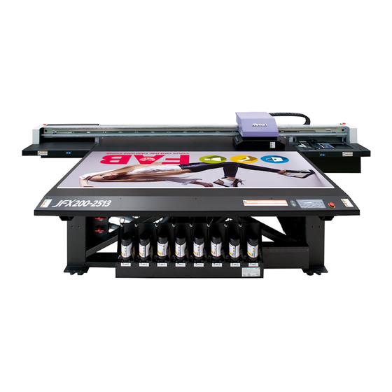
Model Width Depth Height Gross weight JFX200-2513 4400mm 2450mm 1250mm 650kg • A service engineer will perform installation work of this machine. At this time, he/ she will contact you and explain about the usage and the installation of this machine. After fully understanding that content, use this machine safely.
-
Page 17: About Fixing Machine
About installing this machine About fixing machine The leg of this machine has the level foot to fix the machine. Before turning the power ON, make sure that the printer body is fixed with the leveling feet. The printer body may start moving during operation if it is not fixed with the leveling feet.
-
Page 18: Names Of Parts And Functions
Names of Parts and Functions Front Side of the Machine Power button Turns on/off the power to Carriage the machine. The carriage is provided with the heads for printing. Waste ink tank Waste ink gathers in this tank. Suction valve Operation panel Switch at setting media.
-
Page 19: Operation Panel
Names of Parts and Functions Operation Panel Use the operation panel to make settings for printing or operate this machine. Press to vacuum the media on Performs the adjusting function the table. such as “Drop.POScorrect” and “Feed COMP.” POWER Lamp Press to elevate the carriage.
-
Page 20: Carriage
Names of Parts and Functions Carriage The carriage is provided with the heads for printing and LED UV unit. • Do not expose your naked eyes directly to the light irradiated from the LED UV when it lights. • Do not touch the LED UV unit when it is being lit or just after it is set OFF.
-
Page 21: Connecting Cables
Connecting Cables Connecting USB2.0 Interface Cable Connect the PC and this machine with the USB2.0 interface cable. • Your RIP must be compatible with USB 2.0. • Contact a RIP maker near your location or our office when the USB2.0 interface is not attached to the USB cable Notes on USB 2.0 Interface •…
-
Page 22: Connecting Power Supply Cable
Connecting Cables Removing USB memory If a USB memory module is inserted in the personal computer to which a JFX200 machine is connected, click «Stop» in the «Safely Remove Hardware» window by following the instructions given there first and then remove the module.
-
Page 23: Setting Ink Bottles
Setting ink bottles Take out the ink bottle, and slowly shake it twenty times and more. • To prevent ink from leaking when you shake it, wear gloves and cover the ink bottle cap with a paper towel etc. Being in that status, slowly shake it twenty times and more by flowing ink. •…
-
Page 24
(2) Tighten the specialized cap using the tightening jig. Tightening jig Align the with the tightening jig. • Tighten until the arrows on the tightening jig are aligned. • Do not tighten the dedicated cap too much. Doing so may damage it. (3) Turn the bottle upside-down and check that ink does not leak. -
Page 25
Setting ink bottles Move the lever on the tank completely from the right to the left side. Insert the IC chip. • Insert the IC chip with the left side with metal upward. If you insert the wrong side by accident, it causes faulty or damage of the IC chip. -
Page 26
Replace the ink bottle Perform as follows when [INK END] or [INK NEAR END] is displayed on the display. When [INK END] is displayed Move the lever on the tank completely from the left to the right end. • Do not ever rotate the ink bottle at all after setting it into the tank. -
Page 27
Setting ink bottles Remove the cap from the used ink bottle. • Use the tightening jig to remove the cap if it is difficult to remove. Refer to P.1-9 “Setting ink bottles” to set the new ink bottle. • Do not leave an ink bottle with the specialized cap attached in a location where it is exposed to light for a long period of time. -
Page 28
For Ink bottle lamps The condition of the ink bottles set in the machine is confirmable with lamps located over the ink bottles. Ink bottle lamps Condition of Ink bottle lamp Description No error There is less ink in the ink bottle (Near End). Or, one month has passed from the Blinks in red. -
Page 29: Caution In Handling Of Ink Bottles
• Do not shake ink bottles violently. This may result in ink leakage from the ink bottles. • Never refill the ink bottles with ink. This may result in troubles. MIMAKI will not bear any responsibility for any damage caused by the use of the ink bottles refilled with ink.
-
Page 30: Media
Media Usable media sizes and notes for handling are described. Usable sizes of media Model JFX200-2513 2580mm Maximum width Maximum length 2040mm 2500mm Maximum printing width Thickness Less than 50mm Weight Less than 325kg *1. A rough guide is 50 kg per 1 m Caution in handling of medias Pay attention to the followings for handling of medias.
-
Page 31: Basic Operations
Chapter 2 Basic Operations This chapter describes procedures and setting methods for ink and media preparation, and printing. Workflow …………2-2 About head cleaning ……..2-15 Perform head cleaning depending on the Turning the Power ON/OFF ……2-3 test printing result ……..2-15 Turning the Power ON ……..
-
Page 32: Workflow
Workflow Turning the Power ON/OFF Referring to “Turning the Power ON/OFF” P.2-3). Setting a Media Referring to “Setting a Media” ( P.2-5). Move the irradiation position of Referring to “Move the irradiation position of the the UV lamp UV lamp” ( P.2-8).
-
Page 33: Turning The Power On/Off
Turning the Power ON/OFF Turning the Power ON Power button Push the power button. • Push the power button located on the left side of the operation panel. • The firmware version is displayed when the power is turned ON. J F X 2 0 0 S t a r t — u p V e r…
-
Page 34: Turning The Power Off
Turning the Power ON/OFF Turning the Power OFF When having ended the operation of the machine, turn the power OFF by pressing the power button located on the front side. Check the following items when turning the power OFF. • If the machine is receiving data from the PC or if there is any data that has not been output yet •…
-
Page 35: Setting A Media
Setting a Media This machine can be used with a leaf media. For usable medias, refer to P.1-16 “Usable sizes of media”. Setting the Media • If, within the absorption area, there are suction holes not closed by the media, close such suction holes placing thin sheet form material such as paper, film or tape.
-
Page 36
On the absorption area The absorption area of JFX-2513 is shown in the following figure. Origin Seal indicating the point of origin Provided at the 4 corners of the table. • When changing the point of origin, please refer to P.3-2 . -
Page 37
Setting a Media About the media guide hole There are guide holes into which the attached positioning pin is inserted at the edge of the table (two sides of upper and lower of the table). Use these as a guide to set the media straight. •… -
Page 38: Move The Irradiation Position Of The Uv Lamp
Move the irradiation position of the UV lamp When printing with this machine, it is necessary to move the LED UV position according to ink to use (color ink/ white ink). This machine provides three printing methods: Single-layer printing: printing color ink layer on media …
-
Page 39
Move the irradiation position of the UV lamp 4-colors + clear ink + white ink (M/K/C/Y/CL/CL/W/W) Printing method UV lamp position Single-layer print that prints color ink layer on media. • Move the right and left UV lamp to the position at 0mm. Single-layer print that prints clear ink layer on media. -
Page 40
(2) Adjustment on LH-100 4-colors (M/M/K/K/C/C/Y/Y) Printing method UV lamp position Single-layer printing: printing color ink layer on media. • Move the right and left UV lamp to the position at 65mm. 4-colors + white ink (M/K/C/Y/M/C/W/W) Printing method UV lamp position Single-layer print that prints color ink layer on media. -
Page 41
Move the irradiation position of the UV lamp • The left and right of the UV lamp at 0mm position at Three layers print that overlap the white ink layer on the primer printing primer layer and then overlap the color ink layer Move to 65mm position at the white and color printing •… -
Page 42
Positioning method of UV lamp This part explains the method to move the UV lamp for right and left of the carriage. Loosen the screw of the lamp you move, slide it. Align the top edge of the arrow with the scale. Screw Screw •… -
Page 43: Test Printing
Test Printing Print a test pattern to check that there are no discharging defects such as nozzle clogging (slight touching of ink or nozzle missing). Relationship between head row and test pattern The relations between head row and test pattern print position are as follow. Head 1 Head 2 Pattern of…
-
Page 44
Test Printing Test Printing Print a test pattern to check that there are no discharging defects such as nozzle clogging (slight touching of ink or nozzle missing). In addition, you can select the orientation of the test pattern to print from two types in order to perform test printing repeatedly. -
Page 45: Head Cleaning
Head Cleaning About head cleaning Check the printed test pattern result and perform cleaning depending on the status. Select one from the three types below: SOFT : When lines are bent, when any line is missing NORMAL : When any line is missing, when colors are mixed HARD : When poor image quality cannot be improved even by NORMAL or SOFT cleaning Perform head cleaning depending on the test printing result…
-
Page 46: Printing Data
Printing Data Starting a Printing Operation Setting a Media ( P.2-5) (1) Open/Close the suction valve adjusting to the media size. (2) Press the key to light the VACUUM lamp and vacuum the media. Press the key in LOCAL. • The screen changes to REMOTE, and data can be received from the PC. With/ without MAPS setting Transmit data to be printed from the PC.
-
Page 47: Stopping A Printing Operation Halfway
Printing Data Stopping a printing operation halfway Perform the following operation when stopping a printing operation halfway. Press the key during printing. < L OCA L > DA T A REMA I N • The printing operation stops. • Interrupt data sending at the PC side during the data is sent from the •…
-
Page 48: Move The Y-Bar
Printing Data Move the Y-bar When you wish to check the printing results etc., you can move the Y-bar. Set the evacuation position (view position) of the Y-bar in advance. Setting the view position Press the key in LOCAL. F UNC T I ON V I EW [ EN T ] Press the…
-
Page 49
Chapter 3 Extended Functions This chapter describes the operation procedures for using the machine more conveniently and each setting procedure. Changing origin ……….3-2 Setting Work Cange ……..3-17 Changing origin with JOG keys ….3-2 Setting Ionizer ……….3-18 Changing origin with FUNCTION menu ..3-3 Setting Auto Cleaning ………3-19 Registering the thickness of the media .. -
Page 50: Changing Origin
Changing origin The default origin position can be changed. There are following 2 changing methods. Changing with the JOG keys Changing with the ÅgORIGINÅh in the FUNCTION menu Changing origin with JOG keys Press in the local. OR I G I N S E T UP 0 .
-
Page 51: Changing Origin With Function Menu
Changing origin Changing origin with FUNCTION menu To precisely set the origin of coordinates, set its X- and Y- coordinates from the FUNCTION menu. This setting value becomes the origin position (0, 0). Press the key in LOCAL. F UNC T I ON V I EW [ EN T ] Press…
-
Page 52: Registering The Thickness Of The Media
Registering the thickness of the media Register the thickness of loading media. There are three types of registering; “Register the thickness of the media manually”, “Adjust the gap with the keys”, and “Measuring the thickness of the media automatically”. Register the thickness of the media manually Press the key in the local.
-
Page 53: Measuring The Thickness Of The Media Automatically
Registering the thickness of the media Measuring the thickness of the media automatically Thickness of media is automatically measured with the gap pin on the left of the carriage. Set a media. • Be sure to set a media on the printing area. If measured automatically without media, the head can break.
-
Page 54: Registering Head Gap Value
Registering Head gap value Set the head gap (height from the media to the nozzle plane of the heads). When the carriage is to move above the platen for printing or maintenance, it moves while keeping the head gap at the preset value. The upper limit of the head gap varies with media thickness.
-
Page 55: List Of Functions
List of Functions This section describes the overview of each function to be set and set values that can be registered in user types. • About default “HOST” function You can operate this by the setting value specified in RIP software. When you set to other than “HOST”, it operates by that setting value, not by the instruction from RIP software.
-
Page 56: Correct The Ink Drop Position For Bidirectional Printing
Correct the ink drop position for bidirectional printing When the condition for printing (media thickness/head height/etc.) has been changed, perform the following operation to correct the ink drop position for bidirectional (Bi) printing and obtain the proper printing result. Example of a Drop Position correct Printed Pattern Output direction The dots at the fourth position counted from the zero…
-
Page 57
Correct the ink drop position for bidirectional printing Press the key. • Displays the next pattern input. • Repeat step7. Press the key several times to end the setting. Performing to correct the dot position without You can select “DROP.POScorrect” by using the key in the Local without pressing the key. -
Page 58: Setting Logical Seek
Setting Logical Seek The motion of Head varies depending on the set of Logical-seek. • You cannot specify the logical seek at the RasterLink side. When you set this machine to “Host”, printing will be performed in “LOGICAL SEEK=ON” status. MACHINE LENGTH MEDIA Movement of heads when…
-
Page 59: Setting Uv Mode
Setting UV mode Set the emission pattern and illumination intensity for the UVLED. Press the key in LOCAL. F UNC T I ON V I EW [ EN T ] Press to select [SET UP], and the press S E T UP F E ED COMP .
-
Page 60: Perform Setting To Reduce Stripes Between Passes
Perform setting to reduce stripes between passes What is the MAPS Function? If performing media correction does not resolve feeding stripes, use the MAPS (Mimaki Advanced PassSystem) function to disperse the pass boundary to make the feeding stripes less visible.
-
Page 61: Setting Maps2 Function (4 Color)
Perform setting to reduce stripes between passes Press the key. S E T UP MA PS [ EN T ] Press the key several times to end the setting. Setting MAPS2 Function (4 color) Press the key in LOCAL. F UNC T I ON S E T UP [ EN T ] Press the…
-
Page 62: Setting Maps2 Function (4Color + Special Color Ink)
Press to select pattern to print. MA PS 2 P A T T ERN : 2 • AUTO : A pattern that matches the print mode will be set automatically. • Pattern 1 to 5 : The pattern that you select will be printed. •…
-
Page 63
Perform setting to reduce stripes between passes Press the key. MA PS : OF F Press to select “MAPS2” and press the MA PS 2 : AU TO key. • Set Value:MAPS1, MAPS2, OFF • If you selected OFF, proceed to step 11. Press to select “AUTO”… -
Page 64: Perform Setting To Reduce Stripes Between Passes
Perform setting to reduce stripes between passes (6) Press the key. < S POT > • A screen for setting SMOOTHING.LV will appear. SMOOT H I NG L V . : AU TO (7) Press to set the SMOOTHING LV. . <…
-
Page 65: Setting Work Cange
Setting Work Cange Set whether to return to the local mode or keep the remote mode after online drawing. Press the key in LOCAL. F UNC T I ON V I EW [ EN T ] Press to select [SET UP]. F UNC T I ON S E T UP [ EN T ]…
-
Page 66: Setting Ionizer
Set the operation when the optional ionizer is installed. • If you have not installed the optional ionizer, these settings will not appear. If you have installed the ionizer but these settings fail to appear, contact the distributor or a MIMAKI sales office or call center. Press the key in LOCAL.
-
Page 67: Setting Auto Cleaning
Setting Auto Cleaning You can set the machine so that it counts the number of printed files or the length after printing has been completed, and performs cleaning automatically if required. The machine can perform a stable printing operation with its heads always kept clean. Press the key in LOCAL.
-
Page 68: Setting Nozzle Face Cleaning Time
Setting nozzle face cleaning time Cleaning of the head nozzle face is performed automatically before printing begins in order to remove any ink adhering to the nozzle face. Press the key in LOCAL. F UNC T I ON V I EW [ EN T ] Press to select [SET UP].
-
Page 69: Other Settings
Other Settings Change the settings according to the types of use. Press the key in LOCAL. F UNC T I ON V I EW [ EN T ] Press to select [SET UP]. F UNC T I ON S E T UP [ EN T ] Press the key.
-
Page 70: Machine Settings
Machine Settings Machine settings are functions for using this machine easily. The following items can be set in Machine settings. Item Set value Default Meaning When no operation has been performed for the NONE/ AUTO Power-off 30min set time, the power supply is automatically P.3-22) 10 ~ 600min turned “OFF”.
-
Page 71: Setting Time
Machine Settings Setting Time You can set time of your country (time difference). Press the key in LOCAL. F UNC T I ON V I EW [ EN T ] Press to select [MACHINE SETUP]. F UNC T I ON MACH I NE SE T UP [ EN T ] Press the…
-
Page 72: Setting Units
Setting Units Units used by this machine are set. Press the key in LOCAL. F UNC T I ON V I EW [ EN T ] Press to select [MACHINE SETUP]. F UNC T I ON MACH I NE SE T UP [ EN T ] Press the key.
-
Page 73: Setting A Key Buzzer
Machine Settings Setting a KEY BUZZER You can turn off the buzzer sound when pressing the key. Press the key in LOCAL. F UNC T I ON V I EW [ EN T ] Press to select [MACHINE SETUP]. F UNC T I ON MACH I NE SE T UP [ EN T ] Press the…
-
Page 74: Setting A Language
Machine Settings Setting a LANGUAGE You can change the displayed language. Press the key in LOCAL. F UNC T I ON V I EW [ EN T ] Press to select [MACHINE SETUP]. F UNC T I ON MACH I NE SE T UP [ EN T ] Press the key.
-
Page 75: Initializing The Settings
Initializing the Settings You can return the setting of “SETUP”, “MAINTENANCE” and “MACHINE SETUP” to the status before shipment. Press the key in LOCAL. F UNC T I ON V I EW [ EN T ] Press to select [MACHINE SETUP]. F UNC T I ON MACH I NE SE T UP [ EN T ]…
-
Page 76: Confirming Machine Information
Confirming Machine Information The information of this machine can be confirmed. The following items can be confirmed as machine information. Item Description WIPING PRINT LENGTH PRINT AREA USAGE The information of this machine can be confirmed. USE TIME WASTE INK TANK UV LAMP VERSION This displays the firmware version of the machine.
-
Page 77: Check The Machine Version Information
Confirming Machine Information Check the machine version information Press the key in LOCAL. F UNC T I ON V I EW [ EN T ] Press to select [INFORMATION]. F UNC T I ON I N FORMA T I ON [ EN T ] Press the key.
-
Page 78: Displaying The Information Of This Machine
Confirming Machine Information Displaying the Information of this machine Press the key in LOCAL. L US — 1 5 0 MMKKCCK K REMA I N 9 9 9 9 9 9 9 9 The information is displayed sequentially with the key .
-
Page 79: Maintenance
Chapter 4 Maintenance This chapter describes the items required to use this machine more comfortably, which are the methods for the daily care, the maintenance of the ink unit etc. Maintenance ……….4-2 Automatic Maintenance Function ….4-25 Precautions for Maintenance …… 4-2 Setting the Refreshing Intervals ….4-25 About Cleaning liquid ……..
-
Page 80: Maintenance
Maintenance Maintain the machine regularly or as necessary so that its accuracy will be maintained and it can continue to be used for a long time. Precautions for Maintenance Pay attention to the following items when maintaining this machine. • When using cleaning solution for maintenance, be sure to wear the supplied protective glasses. •…
-
Page 81: Mbis Maintenance
Maintenance MBIS Maintenance There is a cotton pad attached to the cap wiper section on the rear of the tank that is used to wipe off any ink adhering to the underside of the cap when replacing ink bottles of the MBIS. Periodically replace the cotton pad.
-
Page 82: Maintaining The Capping Station
Maintaining the Capping Station Maintain the ink cap, wiper, etc. located in the capping station. (SATION MAINT.) The ink cap and wiper function as follows. • Wiper : It wipes off ink sticking to the head nozzles. • Ink cap : It prevents the head nozzles from clogging due to dryness. As the machine is used repeatedly, the wiper and ink cap gradually become dirty with ink, dust, etc.
-
Page 83
Maintaining the Capping Station Remove the wiper. Projection • Pull out the wiper by holding the protrusions at its both ends. Clean the wiper and bracket. Wiper • Wipe off the ink sticking to the wiper and bracket with a clean stick dipped in cleaning liquid for maintenance. -
Page 84
Clean the cap rubber and cap rubber cover. Cap rubber • Wipe off the ink sticking to the cap rubber and cap rubber cover with a clean stick dipped in cleaning liquid for Cap rubber maintenance. cover Wipe off so that cleaning solution for maintenance will not remain. -
Page 85: Cleaning The Around Station
Maintaining the Capping Station Cleaning the around station It is recommended that the wiper and cap be cleaned frequently in order to maintain the high image quality of the machine and keep the machine itself in good working order. • Clean the station and the area around it about twice a week (it varies, depending on frequency in the use of the machine).
-
Page 86: Cleaning The Head And The Area Around It
Cleaning the Head and the Area around It Because the head employs a very precise mechanism, due care needs to be taken when it is cleaned. Using a clean stick, etc., rub off gelatinous ink or dust that may stick to the lower part of the slider and the area around the head.In doing so, never rub the nozzles of the head.
-
Page 87
Cleaning the Head and the Area around It Wipe ink sticking to the side of the head off with a clean stick. • Never rub the nozzles. The nozzle part (Never Clean the side surface of the head (shown in deep gray) with a clean stick. touch it.) Clean with a clean stick. -
Page 88: Washing The Ink Discharge Passage (Disway Wash)
Washing the Ink Discharge Passage (DISWAY WASH) Wash the ink discharge passage regularly to prevent the head nozzles from clogging due to ink coagulation inside the passage. Press the key in LOCAL. CARR I AGE OU T [ EN T ] Press to select [DISWAY WASH].
-
Page 89: When The Machine Is Not Used For A Long Time (Custody Wash)
Cleaning the Head and the Area around It When the Machine Is Not Used for a Long Time (CUSTODY WASH) When the machine is not going to be used for a week or more, use the cleaning function for custody to clean the head nozzles and ink discharge passage.After this, keep the machine in custody.
-
Page 90
Press the key. CA P C L E AN I NG COMP L E T ED ( NEX T ) [ EN T ] • The carriage moves onto the platen. • Until wiper cleaning is competed, [COMPLETED (NEXT): ENT] is displayed on the screen. After the work up to the step 6 is completed, press the key. -
Page 91
Cleaning the Head and the Area around It Fill up the cap with cleaning solution for maintenance, using a dropper. • Fill the cap with the cleaning solution just before the solution overflows from the cap. Press the key. CUS TODY WA SH P L E A SE WA I T •… -
Page 92: When Nozzle Clogging Cannot Be Solved
When Nozzle Clogging Cannot Be Solved When nozzle clogging cannot be solved even after the head cleaning ( P.2-15) has been done, perform the following two functions: HEAD FILLUP • Fill the head with ink. ( P.4-14) NOZZLE WASH • Wash the head nozzle. ( P.4-15) •…
-
Page 93: Washing Of Head Nozzle
When Nozzle Clogging Cannot Be Solved Washing of Head nozzle Perform cleaning of the nozzles in the heads to prevent them being clogged with coagulated ink. Is [INK END] displayed? • The ink is absorbed when the nozzles are washed. Check the items on the At this time, if the state of «INK END»…
-
Page 94
Cap rubber Clean the cap rubber and cap rubber cover. • Wipe off the ink sticking to the cap rubber and cap rubber cover with a clean stick dipped in cleaning solution for Cap rubber maintenance. Wipe off so that cleaning solution for cover maintenance will not remain. -
Page 95: If Nozzle Missing Due To Color Mixture Of Ink Or Aeration
When Nozzle Clogging Cannot Be Solved If nozzle missing due to color mixture of ink or aeration If nozzle missing occurs due to color mixture of ink in the head or aeration, push ink or air in the head out from the port.
-
Page 96
Open, one at a time, the ink port caps on the side you selected in step 3. • Be sure to carry out air purging on only one port at a time. • Do not open the port cap at the side you did not Port1 select in the Step 3. -
Page 97
When Nozzle Clogging Cannot Be Solved Perform the procedures from 9 to 10 on all ports which have to be purged the air. • Attach the jig to the port from which you want to purge air and press the key to release air from the machine. -
Page 98: Alternative Nozzles For Printing, When Nozzles Missing Can Not Be Improved
Alternative nozzles for printing, when nozzles missing can not be improved NOZZLE RECOVERY: When nozzles missing can not be improved at specific points, other good nozzles can be used as alternatives for printing. The head of this machine consists as the right figure. You can set the recovery by specifying the nozzle line each for the H1-2 (Head 1-2).
-
Page 99
When Nozzle Clogging Cannot Be Solved Press to select the Nozzle line that needs SE L EC T NOZ Z L E NOZZLE RECOVERY and press the key. : H 1 — A Nozzle line: A,B,C,D Head No.: H1 or Register the Nozzle number that needs NOZZLE H 1 — A RECOVERY and press the… -
Page 100
Check if the registered nozzle is recovered You can check whether registered nozzle has been successfully recovered. With the following settings “ON”, you can print a test pattern using a recovered nozzle when test print ( P.2- 13). Select [NOZZLE RECOVERY] of the maintenance menu. -
Page 101
When Nozzle Clogging Cannot Be Solved At the time of the start of printing, check whether or not there is a nozzle that can not be recovered Depending on the print conditions that have been set, there are times when it can not be recovered even register the nozzle recovery. -
Page 102
When Nozzle Clogging Cannot Be Solved Clear the set value Select [NOZZLE RECOVERY] of the maintenance menu. (1) Press the key in LOCAL. (2) Press to select [MAINTENANCE] and press the key. (3) Press to select [NOZZLE RECOVERY]. (4) Press the key. -
Page 103: Automatic Maintenance Function
Automatic Maintenance Function To use this machine comfortably, you can set various maintenances to be performed automatically. Here, set performing intervals of various automatic maintenances. You can prevent troubles such as ink clogging by performing automatic maintenance periodically (automatic maintenance function). For the auto maintenance functions, the following items can be set: •…
-
Page 104: Setting The Cleaning Intervals
Automatic Maintenance Function Setting the Cleaning Intervals The cleaning type and the interval between each cleaning operation are set. Select [AUTO MAINT.] of the maintenance menu. (1) Press the key in LOCAL. (2) Press to select [MAINTENANCE] and press the key.
-
Page 105: Replacing Consumables
Replacing consumables Replacing the wiper The wiper is consumable.When the display indicates that it is necessary to < L OCA L > replace the wiper, immediately replace the wiper with a new one. R e p l a c e a WI P ER [ M N T ] Also, wipe ink sticking to the lower surface of the slider off.
-
Page 106: If A Waste Ink Tank Confirmation Message Appears
If a Waste Ink Tank Confirmation Message Appears Ink used in head cleaning, etc. is stored in the waste ink tank on the lower right side of the machine. This machine counts the accumulated amount of discharged ink. When that reaches a specified amount, the machine displays a confirmation message.(When this message is displayed, consider the replacement of the waste ink tank.) •…
-
Page 107: Disposing Of Waste Ink
Replacing consumables Disposing of waste ink • Be sure to wear the supplied goggles and gloves when disposing the waste ink tank. Otherwise, you may get ink in your eyes. • Do not replace the waste ink tank while this machine operates (during printing or cleaning). •…
-
Page 108
Move waste ink to a polyethylene tank and return the empty waste ink tank to the original position. (1) As indicated in the right figure, move waste ink pooled in the waste ink tank to another polyethylene tank. (2) Hold the handle of the waste ink tank and insert it along the rail. -
Page 109: Replacing The Waste Ink Tank Before The Waste Ink Tank Confirmation Message Is Displayed
Replacing consumables Replacing the waste ink tank before the waste ink tank confirmation message is displayed if you replace the waste ink tank before the waste ink tank confirmation message is displayed (before the 2L tank is 80% (1.6L) full), set the waste ink information to 0% in the Information menu. Perform steps 3 through 6 in “Disposing of waste ink”…
-
Page 110: Replacing The Waste Ink Tank Before The Waste Ink Tank Confirmation Message Is Displayed
Replacing consumables Replacing the waste ink tank before the waste ink tank confirmation message is displayed Set the waste ink information to 0% in the maintenance menu. Perform steps 3 through 6 in «Disposing of waste ink» ( P.4-29) to empty the waste ink tank.
-
Page 111: Refilling Antifreeze Mixed Water
Precautions in handling the antifreeze liquid • Be sure to wear goggle and gloves for handling the antifreeze liquid. • Use the recommended antifreeze liquid by Mimaki. If not, the cooling device may be broken. (Supplied antifreeze liquid :1000cc x 2 bottles) •…
-
Page 112: Refill Cooling Water
Refill cooling water If an error of lack of water, refill cooling water. To fill up its capacity, about 500cc refill is required. • If leave the error message of lack of water without refilling cooling < L OCA L > water after one week, the error display on the display switches to RE F I L L WA T ER «REFIL WATER».
-
Page 113
Refilling antifreeze mixed water Refill antifreeze liquid. • Fill the antifreeze liquid from the feed-water inlet. • Fill the syringe with mixed water and inject while checking the level indicator. Stop injecting when the red part is visible. • Be sure to check the level indicator as you inject the mixed water. -
Page 114: Exchange The Flushing Filter
Exchange the flushing filter • Cleaning liquid for maintenance (SPC-0568) Tools required for Exchabge • Waste cloth • Gloves • Goggles • Be sure to wear the supplied goggles and gloves when exchanging theflushing filter. Since the ink is absorbed in the Flushing filter, you may get ink in your eyes. If a Flushing Filter Exchange Message Appears The flushing filter needs to be replaced periodically.
-
Page 115: Replacing The Flushing Filter Before The Replacement Message Is Displayed
Exchange the flushing filter Replacing the flushing filter before the replacement message is displayed Select [STATION] of the maintenance menu. (1) Press the key in LOCAL. (2) Press to select [MAINTENANCE] and press the key. (3) Press to select [STATION]. (4) Press the key.
-
Page 116
4-38… -
Page 117
Chapter 5 Troubleshooting This chapter describes the corrective measures to be taken for a phenomenon suspected to be trou- ble and the procedures to clear the error number displayed on the LCD. Troubleshooting …………….5-2 Power does not turn on …………..5-2 The machine does not start printing ……….5-2 Image quality is poor ……………5-3 Nozzle is clogged …………….5-3… -
Page 118: Troubleshooting
Troubleshooting Take appropriate actions as described below before taking the trouble as a failure. If still the problem is not solved after troubleshooting, contact your dealer or an office of MIMAKI. Power does not turn on In most cases, this is due to improper connection of the power cable for the machine or computer. Check that the power cable is connected properly.
-
Page 119: Image Quality Is Poor
This section describes the corrective actions to be taken in case the image quality is not satisfactory. Take remedy for particular problems with image quality. If the remedy does not work, contact your dealer or an office of MIMAKI. Phenomenon Measures (1) Execute the head cleaning.
-
Page 120: Ink Bottle Warning Appears
• Once ink bottle trouble is displayed, do not leave the ink bottle without replacing it for a long time; otherwise, the machine will lose the nozzle clogging prevention function. If nozzles are clogged, the machine must be repaired by MIMAKI’s service engineer. Displaying the description of ink bottle trouble The contents of ink bottle error are confirmable by the following operations.
-
Page 121: If A Message «Shake White Ink Botles» Appears
Troubleshooting If a Message “SHAKE WHITE INK BOTLES” Appears White ink tends to settle, so you must periodically shake the ink bottles. SHAK E WH I T E I NK If using white ink, a message will be displayed periodically instructing you to BOT L E S [ EN T ] shake the white ink bottle.
-
Page 122: If An Error Related To The Sub Tank Occurs (Error 618 To 61B)
If an error related to the sub tank occurs (Error 618 to 61b) The Error 618 to 61b are related to the sub tank. Execute following procedures when an error about sub tank occurs, or when the nozzle is not unclogged after cleaning.
-
Page 123: If Negative Pressure Abnormality Occurs
Troubleshooting If negative pressure abnormality occurs By the environment or aging, the pressure controlled in this machine may exceed the control range. If an error related to pressure abnormality occurs, perform the procedures below: • If pressure abnormality occurs, immediately adjust the pressure with the following procedures and return it to the normal value.
-
Page 124
Troubleshooting Press the key. P L E A SE WA I T • The error is released and the negative pressure control starts. • When an error occurs even after you adjusted the pressure, contact your local distributor to call for service. -
Page 125: Warning / Error Messages
Warning / Error Messages If some trouble occurs, the buzzer sounds and the display shows a corresponding error message. Take an appropriate remedy for the displayed error. Warning messages Errors when performing operations Message Cause Solution • Check the ink bottle for the supply path C A N ‘…
-
Page 126
Message Cause Solution The value of the negative pressure • Perform “PRESSURE ADJUST” ( P.5- < L OC A L > sensor is abnormal. N E G A T I V E P R E S S U R E 7) of the maintenance. -
Page 127
Warning / Error Messages Ink Error Ink error is displayed also in the local guidance. ( P.3-30) Message Cause Solution • Remove the ink bottle generating the I N K : — — — — Y Y K K warning once and install it again. The IC chip of the ink bottle cannot be •… -
Page 128: Error Messages
Error messages When an error message is displayed, eliminate the error according to the chart below. If the same error message appears again, contact your dealer or an office of MIMAKI to call for service. Message Cause Solution There is an abnormality in the parame-…
-
Page 129
Warning / Error Messages Message Cause Solution An error occurred in the main PCB 35- E R ROR 1 5 8 2V power supply. M a i n P C B V 3 5 2 COM driver becomes the high tem- E R ROR 1 5 f perature. -
Page 130
Message Cause Solution E R ROR 3 0 4 USB device initialization failure. U S B I N I T E R R Occurrence of a time out error on a E R ROR 3 0 5 USB device. U S B T I ME OU T E R ROR 4 0 1 An excessive load was applied to the X •… -
Page 131
Warning / Error Messages Message Cause Solution • Perform “SUB TANK” ( P.5-6) of the maintenance. Also check the remaining Ink could not be supplied to the sub amount of ink in the ink bottle. Even if you E R ROR 6 1 b tank. -
Page 132: System Halt
Warning / Error Messages Message Cause Solution E R ROR 7 1 9 Ink heater PCB fuse is out. I n k H e a t e r P C B F u s e : 1 2 • Turn off the main power to the machine and turn it on after a while.
-
Page 133
Chapter 6 Appendix This chapter contains the lists of the specifications and functions of this machine. Specifications ………………6-2 Machine specifications …………..6-2 Ink specifications …………….6-3 Setting orders depending on ink type ……….6-4 Setting orders of ink bottles ………….6-4 Warning labels ……………..6-6 Sheet for inquiry …………….6-8 Function Flowchart …………….6-10… -
Page 134: Specifications
Specifications Machine specifications Item Specifications Method Drop-on-demand piezoelectric print heads Print head Specification 2 heads: 2-layered staggered arrangement in 1-line 300x450HQ : Bi/Uni 6/12 pass 600×600 : Bi/Uni 8/16 pass 4-colors 600×900 : Bi/Uni 12/24 pass 1200×1200 : Bi/Uni 16/32 pass Printing mode (scan x feed) 300x450HQ : Bi/Uni 12/24…
-
Page 135: Ink Specifications
Transportation at temperature of 40˚C is permitted within a month.) Do not use any ink other than MIMAKI designated ink. Also, do not disassemble the ink bottles or refill or replenish their ink. Ink could freeze if kept in a cold place for an extended period.
-
Page 136: Setting Orders Depending On Ink Type
Setting orders depending on ink type The setting value and the setting orders of the ink bottles differ depending on the ink type you use. Setting orders of ink bottles The order of the ink bottles that are set differs depending on the ink set that is used. 4-colors ink set 4-colors + white ink set 4-colors + clear + white ink set…
-
Page 137
Setting orders depending on ink type 4-colors + clear + primer + white ink set 6-colors + white ink set… -
Page 138: Warning Labels
Warning labels Warning labels are stuck on the machine. Be sure to fully understand the warning given on the labels. If a warning label is illegible due to stains or has come off, purchase a new one from a distributor or our sales office.
-
Page 139
Warning labels 1:Reorder .M909381 2:Reorder .M903330 3:Reorder .M906115 6:Reorder .M902663 7:Reorder .M905980 8:Reorder .M906311 8:Reorder .M906311 8:Reorder .M906311 8:Reorder .M906311… -
Page 140: Sheet For Inquiry
Sheet for inquiry Use this sheet for troubles and abnormal functions of the machine. Fill in the following necessary items, and then fax the sheet to our sales office. Company name Person in charge Telephone number machine model Operating OS Machine information Error message Contents of inquiry…
-
Page 142: Function Flowchart
Function Flowchart < L OC A L > WH I D T H : * * * * mm OR I G I N S E T U P OR I G I N S E T U P 0 . 0 — — — — * * OR I G I N * * OR I G I N S E T U P…
-
Page 143
Function Flowchart OR I G I N S E T U P OR I G I N S E T U P H E A D GA P = * . * mm ME D I A = * . * mm * * P R I N T I NG * * P L E A S E WA I T * * C L E A N I NG * *… -
Page 144
From P.6-10 DROP . POS c o r r e c t DROP . POS c o r r e c t [ E N T ] P R I N T [ E N T ] L H — 1 0 0 MMCC Y Y K K I N K I C C A N ‘… -
Page 145
Function Flowchart * * P R I N T I NG * * P A T T E RN 1 P A T T E RN 2 P L E A S E WA I T 0 . 0 0 . 0 -40 to 40 -40 to 40 WA RN I NG… -
Page 146
From P.6-12 F UNC T I ON V I EW * * MOV I NG NOW* * V I EW [ E N T ] S T A R T [ E N T ] P L E A S E WA I T V I EW S E T V I EW POS S E T V I EW POS… -
Page 147
Function Flowchart ME D I A T H I C K N E S S P L E A S E WA I T T H I C K N E S S CH E C K T H I C K N E S S CH E C K T H I C K N E S S CH E C K CH E C K S T A R T [ E N T ]… -
Page 148
From P.6-14 From P.6-14 MANUAL S E T U P U V MOD E U V MOD E [ E N T ] : HOS T HOST HOST/PATTERN1, 2 S E T U P R E F R E S H R E F R E S H [ E N T ] : HOS T… -
Page 149
Function Flowchart U V MOD E U V MOD E U V MOD E L I GH T A D J U S T : C o l o r : B i Bi / Uni -50 to +50% Color/ White/ Clear ink U V MOD E U V MOD E : P A T T E RN 1… -
Page 150
From P.6-16 F UNC T I ON MA I N T E N A NC E S T A T I ON MA I N T E N A NC E [ E N T ] S T A T I ON [ E N T ] C A RR I AGE OU T [ E N T ]… -
Page 151
Function Flowchart MOV E POS I T I ON C A RR I AGE OU T : S T A T I ON MA I N T . COMP L E T E D [ E N T ] STATION MAINT. / HEAD MAINT. W I P E R C L E A N I NG C A P C L E A N I NG F i l l… -
Page 152
From P.6-18 From P.6-18 From P.6-18 NO Z Z L E R E COV E R Y : CON F I RM ME NU NO Z Z L E R E COV E R Y : CH E C K B E F OR E P R I N T MA I N T E N A NC E A U T O MA I N T . -
Page 153
Function Flowchart CON F I RM ME NU : O F F ON/ OFF CH E C K B E F OR E P R I N T : O F F OFF/ CONTINUE/ STOP R E F R E S H : L v . -
Page 154
From P.6-20 F UNC T I ON MA CH I N E S E T U P A U T O P o w e r — o f f MA CH I N E S E T U P [ E N T ] A U T O P o w e r — o f f [ E N T ]… -
Page 155
Function Flowchart L E NG T H : mm mm / inch R E S E T Settings are initialized E X E CU T E [ E N T ] P L E A S E WA I T * * P R I N T I NG * * P L E A S E WA I T * * P R I N T I NG * *… -
Page 157
JFX200-2513 Operation Manual Apr, 2016 MIMAKI ENGINEERING CO.,LTD. 2182-3 Shigeno-otsu, Tomi-shi, Nagano 389-0512 JAPAN D202563-14-01042016… -
Page 158
FW : 2.0 © MIMAKI ENGINEERING CO., LTD.2016…
-
Page 1
You can also download the latest manual from our website. MIMAKI ENGINEERING CO., LTD. https://mimaki.com/ D203431-12 Original instructions… -
Page 2: Table Of Contents
TABLE OF CONTENTS Foreword……………… vi For Safe Operation …………… viii Symbols ……………….. viii Warnings and Precautions for Use ………… ix Installation Precautions…………… xiv Warning Labels……………. xvi Chapter 1 Before Use Usage Restrictions…………… 1-2 Usage Restrictions……………. 1-2 User Restrictions ……………. 1-2 Area Restrictions ……………. 1-2 Installing this Machine …………..
-
Page 3
Turning the Power On/Off………… 2-3 Turning the power on…………….. 2-3 Turning off the power…………….. 2-3 Setting up the Media………….. 2-5 Setting up the Media……………. 2-5 Move the illumination position of the UV lamp…… 2-8 The best position of the UV lamp for printing…….. 2-8 Adjusting the UV Lamp Position ………… -
Page 4
Nozzle Check Menu………….. 3-33 Nozzle Check Menu List ………….. 3-33 Printing Nozzle Check Flow…………. 3-33 Print Operations During «Nozzle Missing» Judgment and Error Occurrence ……………… 3-34 Printing Nozzle Check Settings ………… 3-34 Auto Nozzle Recovery Settings ………… 3-36 Judgment Condition Settings………… 3-36 Resetting to Default Settings …………. -
Page 5
Flushing Filter ……………. 4-42 Replacing the Flushing Filter ………… 4-42 Replacing the flushing filter before the replacement message is displayed……………… 4-42 Chapter 5 Troubleshooting Troubleshooting ……………. 5-2 Power does not turn on………….. 5-2 Machine does not start printing………… 5-2 Image quality is poor……………. 5-2 Nozzle is clogged……………. -
Page 6: Foreword
Foreword Congratulations on your purchase of UV inkjet printer JFX200-2513EX. JFX200-2513EX is a UV inkjet printer that supports high speed and high image quality, printing with UV ink. l DISCLAMER OF WARRANTY THIS LIMITED WARRANTY OF MIMAKI SHALL BE THE SOLE AND EXCLUSIVE WARRANTY AND IS IN LIEU OF ALL OTHER WARRANTIES, EXPRESS OR IMPLIED, INCLUDING, BUT NOT LIMITED TO, ANY IMPLIED WARRANTY OF MERCHANTABILITY OR FITNESS.
-
Page 7
• Plug the power cord of this printer into an outlet which is isolated from power circuits connected to the television set or radio. Reproduction of this manual is strictly prohibited. All Rights Reserved. © 2019 MIMAKI ENGINEERING Co., Ltd. -
Page 8: For Safe Operation
For Safe Operation For Safe Operation Symbols This manual uses symbols to explain the precautions during use. The indicated symbols differ depending on the contents of the caution. Please understand the meaning of each symbol to use this machine safely and correctly.
-
Page 9: Warnings And Precautions For Use
For Safe Operation Warnings and Precautions for Use l If a problem occurs • If someone swallows ink or cleaning solution by mistake, keep him or her quiet and take them to see a doctor immediately. Do not let allow the person to swallow the vomit. •…
-
Page 10
For Safe Operation • If an ink bottle is moved from a cold place to a warmer place, let it sit for at least three hours before use. • Open the ink bottle just before use and use it up as soon as possible. If the bottles are left open for a long time, the printing quality may degrade. -
Page 11
For Safe Operation • Never use an LED UV unit or UV power supplies other than those recommended by us. Using products besides those recommended by us can cause fire or damage to the equipment. Malfunctions caused due to the use of non-recommended products is out of the scope of warranty, and our company does not assume any responsibility for the same. -
Page 12: Power Supply
For Safe Operation • The included power cable set is for use with this machine only. It cannot be used with other electronic devices. Also, please do not use any power cable set other than the one provided with this machine. Doing so may cause fire or electric shocks.
-
Page 13: Handling Media
For Safe Operation • Using this machine in a low temperature environment can sometimes cause the vacuum to emit a high- pitched sound, but this is not a malfunction. l Anti freezing liquid • Use our exclusive anti freezing liquid. Using any other anti freezing liquid can cause the cooling system to malfunction.
-
Page 14: Installation Precautions
For Safe Operation l Maintenance • To prevent electric shocks during maintenance, always turn the main power switch off, and remove the power plug. Depending on the device, the condenser may require one minute to discharge. After turning the main power switch off and removing the power plug, wait three minutes before working. •…
-
Page 15
For Safe Operation • Places exposed to direct sunlight • Places that are not level • Places where vibrations occur • Places directly exposed to air flow from an air conditioner, etc. • Places where fire is used • Places with lots of dust •… -
Page 16: Warning Labels
Warning Labels Warning Labels The following warning labels are affixed to this machine. Fully understand the contents of the warning labels. If a warning label becomes illegible due to dirt or peels off, purchase a new one from your local distributor or our sales office.
-
Page 17
Warning Labels Order No. Label M909381 M903330 M906115 M902663 M905980 M916117 M909385 M903281 xvii… -
Page 18
Warning Labels Order No. Label M907935 xviii… -
Page 19: Chapter 1 Before Use
Chapter 1 Before Use This chapter This chapter explains what you need to know before use, such as the name of each part of this machine and its installation method. Usage Restrictions ………1-2 Connecting the Cables ……..1 -15 Usage Restrictions ……..1-2 Connecting the USB Cables ….1-15 User Restrictions……..
-
Page 20: Usage Restrictions
Chapter 1 Before Use Usage Restrictions Usage Restrictions This machine can be dangerous due to parts that move at high speeds, parts with high temperature and UV curing units. This machine is to be used only by those having complete understanding of dangers associated with these parts.
-
Page 21: Installing This Machine
Model Width Depth Height Gross weight JFX200-2513EX 4400 mm 2450 mm 1250 mm 600 kg • A service engineer will perform installation work of this machine. At this time, he/she will contact you and explain about the usage and the installation of this machine.
-
Page 22: Fixing This Machine
Chapter 1 Before Use Fixing This Machine The legs of the machine have level feet to fix the machine. Before turning on the power, make sure that the printer body is fixed with the leveling feet. The printer body may start moving during operation if it is not fixed with the leveling feet. •…
-
Page 23: Avoid These While Operating The Printer
Chapter 1 Before Use Avoid These While Operating the Printer Doing the things mentioned below when the printer is in operation might result in an injury. l Do not put your hands or any object on the table Do not put your hands on the movement channel of the carriage when the power is on. Also, do not put anything on the table other than the printing paper.
-
Page 24
Chapter 1 Before Use l Be careful not to get your hands pinched in the gap between the Y-bar and the carriage There is a risk of a person getting handicapped due to crushing or shearing if their hands or other body parts get caught between the Y-bar and the carriage. -
Page 25
Chapter 1 Before Use l Keep your hands away from the Y-bar and the carriage when the power is on There is a risk of hands getting crushed due to the movements of Y-bar and carriage. Keep your hands or other body parts away from this area and the printing range when the power is on. l Be careful not to get your hands caught in the carriage or the maintenance station portion Do not put your hands in the carriage or the maintenance station portion. -
Page 26
Chapter 1 Before Use l Be careful about belt winding malfunction Be careful not to get your hands dragged into the Y-bar belt. There is a risk of hurting your hands or objects getting sucked. l Do not place any object in front of the exhaust port of suction vacuum The object may get deformed due to the heat released from the exhaust port. -
Page 27
Chapter 1 Before Use l Be careful not to accidentally press the key panel switch by mistake Pressing this switch accidentally may cause sudden operation leading to an unexpected accident. l Be careful not to look directly at the UV light Do not directly look at the UV light. -
Page 28
Chapter 1 Before Use l Pay attention to following when replacing the ink • To prevent the ink from sticking to your hands or eyes when it splashes, be sure to wear the included safety glasses and gloves. • Do not pull the ink cover too much. Pulling it too much might damage the tubes and cables. -
Page 29: Names Of Parts And Functions
Chapter 1 Before Use Names of Parts and Functions Front Side of this Machine Power button Turns on/off the power to this machine. Carriage The carriage is provided with the ink heads for printing. Waste ink tank Waste ink gathers in this tank. Suction valve Operation panel Switched when setting the media.
-
Page 30: Operation Panel
Chapter 1 Before Use Operation Panel Use the operation panel to perform settings for printing or operate this machine. [ADJUST] key [VACUUM] key Performs the adjusting functions Press to attach the media on the such as drop position correction. table. [UP] key POWER Lamp [MAINT.] key…
-
Page 31: Carriage
Chapter 1 Before Use Carriage The carriage is provided with the heads for printing and LED UV unit. • Do not look at the light emitted from the LED UV with a naked eye when lit. • Do not touch the LED UV unit when the LED is lit or just after it is set off. You may suffer serious burns, as the unit is very hot.
-
Page 32
Chapter 1 Before Use There is one stop switch on the front side of the machine, and one each on the left and right edge of the Y- bar. When you press the stop switch to stop this machine, follow the procedure given below to release it. (1) Resolve the fault. -
Page 33: Connecting The Cables
Chapter 1 Before Use Connecting the Cables Connecting the USB Cables Connect this machine to the PC using a USB 2.0 interface cable. • Your RIP must be compatible with the USB 2.0 interface. • If the USB 2.0 interface isn’t attached to the PC, contact your nearest RIP manufacturer or our sales office. USB cable Notes on USB 2.0 Interface •…
-
Page 34: Connecting Power Supply Cable
Chapter 1 Before Use Use a USB cable shorter than 5 m. If a longer cable is required, use a commercially available USB 2.0 repeater cable. l Removing a USB Memory If a USB memory module is inserted in the personal computer to which the machine is connected, click [Stop] in the [Safely Removing Hardware] window.
-
Page 35: Connecting A Lan Cable
Chapter 1 Before Use Connecting a LAN Cable Observe the following precautions when connecting the LAN cable. • Make sure you push it in firmly until you hear a clicking sound. • Do not plug or unplug the cable while data is being transferred. LAN cable Printing Data via a Network If you want to print data via a network, you must construct the network in the following environment.
-
Page 36
Chapter 1 Before Use l Connecting through switching hubs Printing cannot be done unless the PCs and devices connected to the printer are 1000BASE-T. After connecting, check the following: 1. Check the printer screen display. – From the LOCAL screen or MEDIA DETECT screen, press the [ENTER] key several times to display the information screen. -
Page 37: Ink Bottles
Chapter 1 Before Use Ink Bottles Types of Usable Inks Following inks can be used with this machine. 4-color + white + clear model Uses one bottle each of cyan, magenta, yellow, and black and two bottles each of clear and white (LUS150, LH100, LUS120) 4-color + white + clear + primer model Uses one bottle each of cyan, magenta, yellow, black, clear, and primer…
-
Page 38
Chapter 1 Before Use Remove the cap of the ink bottle. • When using LUS-150, remove the cap and open the seal attached to the bottle with a cutter. When opening the seal, cut a circle as shown in the following figure. Make sure that the seal does not fall into the bottle. -
Page 39
Chapter 1 Before Use Use a fastening jig to close the specialized cap. Fastening jig Align with each other the arrows shown on the fastening jig • Tighten the fastening jig until the arrows shown on it get aligned with each other. •… -
Page 40
Chapter 1 Before Use Set the ink bottle over the tank. • Move the tank lever completely to the right and set the ink bottle. • Never rotate the ink bottle after setting it over the tank. Doing so may result in ink leakage. Lever Turn the tank lever from right to left. -
Page 41: Replacing An Ink Bottle
Chapter 1 Before Use Insert the Ink IC chip. • Insert the Ink IC chip with its metal part on the left. Inserting an Ink IC chip with its wrong side inward may damage the Ink IC chip or cause it to malfunction. •…
-
Page 42
Chapter 1 Before Use When [INK END] is displayed Turn the tank lever from left to right edge. • Make sure not to rotate the ink bottle. Doing so may result in ink leakage. Lift the ink bottle vertically. • When the ink bottle is removed from the tank, make sure that the light-blocking cover is shut. If the lid is not shut, close it manually. -
Page 43
Chapter 1 Before Use Wipe off the ink adhering to the bottom of the cap with the wiping filter. Cap wiping part Keep the bottle in an upright position and remove any ink adhering to the cap surface by using a disposable wipe such as KimWipe. Remove the cap from the used ink bottle. -
Page 44: If The Light-Blocking Cover Comes Off
Chapter 1 Before Use If the light-blocking cover comes off When the light-blocking cover comes off, light penetrating into the tank may cause the ink to harden. Perform the following steps to reattach the light-blocking cover: Insert the light-blocking cover (one nub) into the cover insertion hole on the tank. While pressing the cover into the cap insertion hole as explained in Step 1, insert the other nub into the other insertion hole.
-
Page 45: Ink Expiration Date
Chapter 1 Before Use Ink bottle lamp status Description No error Blinks in red Only a small amount of ink is remaining (near end) or the ink is one month past its expiration date. It needs to be replaced soon. Lights in red Ink bottle cannot be used either because it is empty or because of some ink error.
-
Page 46: Precautions On Handling Ink Bottles
• Do not shake the ink bottle too vigorously. Vigorous shaking may cause the ink to leak from the bottle. • Never refill an ink bottle. This may cause malfunction. Mimaki bears no responsibility for problems caused by such refilling.
-
Page 47: Media
Chapter 1 Before Use Media Usable media sizes and notes for handling are described below. Usable media sizes Item name JFX200-2513EX Maximum width 2500mm Maximum length 1300mm Maximum print width 2500mm Thickness 50mm or less Weight 325kg or less *1. Roughly 50 kg per 1 m Storing Media Store the media in a dust-proof place with no direct sunlight.
-
Page 48: Notes Regarding Work Environment, Etc
Chapter 1 Before Use Notes Regarding Work Environment, etc. The frequency of configuring print settings and conducting maintenance is largely influenced by the work environment in which printing is performed and the conditions of the used media. Make sure that you have completely understood the following items before using this machine.
-
Page 49: Chapter 2 Basic Usage
Chapter 2 Basic Usage This chapter This chapter explains how to prepare ink/media for printing and the procedures and configuration to be done before printing. Operation flow ……….2-2 Test printing……….. 2 -11 Examples of Plotting Failure ….2-11 Turning the Power On/Off ……2-3 Relation between the head layout and the Turning the power on ……..
-
Page 50: Operation Flow
Chapter 2 Basic Usage Operation flow Turn power On/Off «Turning the Power On/Off» (P. 2-3) Set up the Media «Setting up the Media» (P. 2-5) Move the illumination position of the UV lamp «Move the illumination position of the UV lamp» (P. 2-8) Test printing «Test printing»…
-
Page 51: Turning The Power On/Off
Chapter 2 Basic Usage Turning the Power On/Off Turning the power on Press the power button. • Press the power button located on the left side of the operation panel. Power button • When the power is turned on, the firmware version is displayed. JFX200EX Start-up Ver 1.00…
-
Page 52
Chapter 2 Basic Usage Press the power button to turn off the power. • The power button lamp goes off. • When using this machine again, press the power button and wait until the green lamp is lit. Power button Precautions on turning off the power l Do not pull out the power cord from the power outlet. -
Page 53: Setting Up The Media
Chapter 2 Basic Usage Setting up the Media This machine can be used with a leaf media. For usable media, see «Usable media sizes» (P. 1-29) . Setting up the Media • If a suction hole within the suction area is not covered by the media, lay out a thin sheet material such as paper, film or tape to cover the hole.
-
Page 54
Chapter 2 Basic Usage Suction Area The following figure shows the suction area. Origin sticker Print origin Provided at the four corners of the table. • To change the point of origin, see «Changing the Point of Origin» (P. 3-2). -
Page 55
Chapter 2 Basic Usage Media Guide Holes The table edges (both top and bottom) are provided with guide holes for inserting the layout pins provided with the printer. Use these guide holes to keep the media straight. • A commercially available M3 screw can be used instead of the positioning pin provided with the printer. In that case, screws can be used to secure the media to both the left and front sides of the table. -
Page 56: Move The Illumination Position Of The Uv Lamp
Chapter 2 Basic Usage Move the illumination position of the UV lamp For printing by using this machine, the position of the LED UV needs to be changed in accordance with the ink being used (color ink or special color ink). This machine gives you an option to select one of the following five types of printing methods: •…
-
Page 57
Chapter 2 Basic Usage Ink set Ink type Printing method Print Ink layer Image Lamp layer position (mm) CMYK CMYK CMYK 3-layer Cl CMYK CMYK CMYK 6C+4SP LH-100 Single CMYKLmLc layer LUS-150 2-layer CMYKLmLc CMYKLmLc CMYKLmLc 3-layer Cl CMYKLmLc *1. The above mentioned settings should be followed when prioritizing the image quality and the lamp position should be changed during printing. (The machine stops before clear printing and a warning is displayed on the Raster Link) If it is not possible to change the lamp position during printing, then set the lamp position to 0 mm before printing. -
Page 58: Adjusting The Uv Lamp Position
Chapter 2 Basic Usage Adjusting the UV Lamp Position This section describes how to move the UV lamps located on either side of the carriage. Loosen the screw of the lamp to be moved and slide the lamp to change its position. Align the tip of the arrow with the scale.
-
Page 59: Test Printing
Chapter 2 Basic Usage Test printing Print the test pattern to make sure that there are no ink discharge problems such as clogged nozzle (blurred print or missing nozzles). Examples of Plotting Failure Discharge failure of the head (head nozzle) due to dust is a typical example of plotting failure. Periodically check the condition of the nozzle before output or during output to avoid using it in defective state.
-
Page 60: Relation Between The Head Layout And The Test Patterns
Chapter 2 Basic Usage Relation between the head layout and the test patterns The following figure shows the relation between head layout and the positions of the printed test pattern. Head 1 Head 2 Head 3 ● 4C + 4SP Head 1 Head 2 pattern…
-
Page 61: Taking A Test Print
Chapter 2 Basic Usage Taking a Test Print Print the test pattern to make sure that there are no ink discharge problems such as clogged nozzle (blurred print or missing nozzles). The test pattern alignment direction can be selected for each test printing from the following two types. Select the direction suitable for your printing job.
-
Page 62
Chapter 2 Basic Usage Press the [ENTER] key. • Start the test print. **PRINT** PLEASE WAIT • Once the printing is completed, the display returns to the Step 1. TEST PRINT (FEED DIR.) [ENT] Check the print results. • Under normal circumstances, the operations end here. •… -
Page 63: Head Cleaning
Chapter 2 Basic Usage Head Cleaning Check the printed test pattern results and perform cleaning depending on the symptoms. Head cleaning can be done in three ways. Use them based on the pattern print results. Press the [CLEANING] key in LOCAL mode. CLEANING SOFT [ENT]…
-
Page 64
Chapter 2 Basic Usage l If the image quality does not improve even after head cleaning • Clean the wiper and ink cap. «Cleaning wiper and cap» (P. 4-5) • Perform the nozzle recovery settings. «When Nozzle Clogging Cannot Be Solved» (P. 4-18) 2-16… -
Page 65: Printing The Data
Chapter 2 Basic Usage Printing the Data Starting a Printing Operation Set the media • «Setting up the Media» (P. 2-5) (1) Open or close the suction valve according to the media size. (2) Press the [VACUUM] key to turn on the VACUUM lamp and adsorb the media. Press the [REMOTE] key in LOCAL.
-
Page 66: Aborting A Printing Operation
Chapter 2 Basic Usage Remove the media after the completion of printing. (1) Move the Y-bar outside the table. «Moving the Y-bar» (P. 2-18) (2) Press the [VACUUM] key to turn off suction. (3) Take out the media. • The media may get lifted and the print may get aborted due to the heat generated by the LED UV during printing.
-
Page 67
Chapter 2 Basic Usage Press the [ENTER] key. VIEW MOVE START <ent> Press the key. VIEW SET VIEW POS Press the [ENTER] key. SET VIEW POS **** mm By pressing the keys, set the position to which the Y-bar is to be moved. •… -
Page 68
Chapter 2 Basic Usage 2-20… -
Page 69: Chapter 3 Convenient Usage
Chapter 3 Convenient Usage This chapter This chapter explains the operation procedures and various settings for convenient use of this machine. Changing the Point of Origin ……3-2 Ionizer Settings……….3 -20 Using JOG Keys to Change the Print Origin AUTO CLEANING Settings ……3 -21 …………..
-
Page 70: Changing The Point Of Origin
Chapter 3 Convenient Usage Changing the Point of Origin The factory setting of point of Origin can be changed. It can be changed in one of the two ways. Changing with the JOG keys Changing from «ORIGIN» in the [FUNCTION] menu Media Light pointer mark Table…
-
Page 71: Using Function Menu To Change The Print Origin
Chapter 3 Convenient Usage Using FUNCTION menu to Change the Print Origin When setting an exact origin, set the X and Y coordinates of the origin from the FUNCTION menu. When the origin is set by using this option, the set value becomes the point of origin (0.0). Press the [FUNCTION] key in LOCAL.
-
Page 72: Registering The Media Thickness
Chapter 3 Convenient Usage Registering the Media Thickness Register the thickness of the media to be set. You can register the thickness in the following three methods. • Registering the thickness manually • Selecting with [UP] [DOWN] keys • Checking the thickness automatically Registering the Media Thickness Manually Press the [FUNCTION] key in LOCAL.
-
Page 73: Automatic Checking Of The Media Thickness
Chapter 3 Convenient Usage Press the [ENTER] key. ORIGIN SETUP ORIGIN SETUP HEAD GAP = 1.2 MEDIA THICKNESS = *.* mm Automatic Checking of the Media Thickness Media thickness is automatically checked by the gap pin located at the center of the carriage. Set the media.
-
Page 74: Head Gap Value
Chapter 3 Convenient Usage HEAD GAP Value Set the head gap (height from media to head nozzle surface). When the head is to be moved onto the platen for operations such as printing or maintenance, it moves while keeping the head gap at the pre-set value. The upper limit of head gap varies depending on the thickness of the media.
-
Page 75: Checking The Head Gap Value
Chapter 3 Convenient Usage Checking the Head Gap Value Perform the following operations when you want to check the currently set head gap value. Press the [ENTER] key in LOCAL. Press the [ENTER] key several times to display [HEAD GAP]. •…
-
Page 76: List Of Functions
Chapter 3 Convenient Usage List of Functions This section outlines the various functions and describes their settings. • Default «HOST» function The value specified in the RIP software runs this function. When a value other than «HOST» is specified, the specified value is used instead of waiting for instructions from the RIP software. Note that some functions may not be available depending on the RIP software used.
-
Page 77: Adjusting The Bidirectional Print Drop Position
Chapter 3 Convenient Usage Adjusting the Bidirectional Print Drop Position If you change the printing conditions (such as media thickness and head height), do the following to correct the ink drop position for bidirectional printing (Bi) to acquire the proper printing results: Correcting the Drop Position Set the media and set the print origin.
-
Page 78
Chapter 3 Convenient Usage Press to correct the drop position from pattern 1 onwards. • Corrected value: -40.0 to 40.0 PATTERN 1 • The position at which the outward feed line and the return feed line become one straight line is the correction value. -
Page 79: Setting Logical Seek
Chapter 3 Convenient Usage Setting LOGICAL SEEK The head operations differ depending on the LOGICAL SEEK settings. • LOGICAL SEEK settings cannot be specified in RasterLink. When the machine setting is «HOST» the printing operation is performed considering that the LOGICAL SEEK is «ON». Machine width Media Head movement when…
-
Page 80
Chapter 3 Convenient Usage Press to select the value to be set. • Available settings: HOST/ON/OFF LOGICAL SEEK : ON Press the [ENTER] key. SETUP LOGICAL SEEK [ENT] Press the [END] key several times to end the operation. 3-12… -
Page 81: Setting Uv Level
Chapter 3 Convenient Usage Setting UV LEVEL Set the UV LED irradiation pattern to be used and illumination intensity to be maintained during printing. Press the [FUNCTION] key in LOCAL. FUNCTION VIEW [ENT] Press to select [SETUP], and press the [ENTER] key. SETUP DROP.POScorrect [ENT]…
-
Page 82
Chapter 3 Convenient Usage Press to select the scanning direction, and press the [ENTER] key. • Available settings: Bi (bidirectional)/Uni (unidirectional) UV LEVEL : Bi Press to select the printing pattern, and press the [ENTER] key. • Available settings: PATTERN 1, 2, and onwards/NO PRINT •… -
Page 83: Reducing Stripes Between Passes
Reducing Stripes Between Passes MAPS Function If the feed lines do not disappear even after performing media feed correction, use the MAPS (Mimaki Advanced PassSystem) function to disperse the pass boundary to make the feed lines less visible. With this machine, you can use the MAPS2 function.
-
Page 84
Chapter 3 Convenient Usage Press to select «AUTO» or «MANUAL». • AUTO: Settings are performed automatically according to the printing conditions. • MANUAL: You can adjust the settings manually. MAPS 2 : MANUAL • If the feed stripes and uniformity of density are not improved by AUTO settings, adjust using MANUAL settings. -
Page 85
Chapter 3 Convenient Usage Press to set the [SPOT]. • AUTO: Patterns are set automatically depending on the printing conditions. • PATTERN 1 to 5: The pattern that you select is printed. < SPOT > PATTERN: 1 Press the [ENTER] key. •… -
Page 86
Chapter 3 Convenient Usage Press to set the [TYPE/LV.]. • TYPE1 10 to 100%: Set a value according to the printing conditions. • TYPE2 10 to 100%: Set a value according to the printing conditions. < CLEAR TYPE/LV.: AUTO • The effects of MAPS2 differ depending on the images to be printed. Change print patterns, and check the effects in advance before using the MAPS2 function. -
Page 87: Work Change Settings
Chapter 3 Convenient Usage WORK CHANGE Settings Set whether to return to LOCAL mode or keep the REMOTE mode after online plotting is complete. Press the [FUNCTION] key in LOCAL. FUNCTION VIEW [ENT] Press to select [SETUP]. FUNCTION SETUP [ENT] Press the [ENTER] key.
-
Page 88: Ionizer Settings
Chapter 3 Convenient Usage Ionizer Settings Set the operations when the optional ionizer is installed. • These settings are not displayed if the optional ionizer is not installed. If this setting is not displayed even though the ionizer is installed, contact your local distributor, or our sales office or call center. Press the [FUNCTION] key in LOCAL.
-
Page 89: Auto Cleaning Settings
Chapter 3 Convenient Usage AUTO CLEANING Settings You can set this function so that it counts the number of printed files or printed length after printing is complete, performs cleaning automatically if required. The machine can deliver stable output if its heads are always kept clean. Press the [FUNCTION] key in LOCAL.
-
Page 90
Chapter 3 Convenient Usage Press to set a cleaning type. • Available settings: NORMAL/SOFT/HARD TYPE : NORMAL Press the [ENTER] key. Press the [END] key several times to end the operation. • Depending on the state of the head, there are cases in which the print defects are not corrected even after running this function. -
Page 91: Setting Nozzle Surface Cleaning Frequency
Chapter 3 Convenient Usage Setting Nozzle Surface Cleaning Frequency This function automatically cleans the nozzle face of the head and removes the ink droplets clinging to the nozzle face before or during printing. Press the [FUNCTION] key in LOCAL. FUNCTION VIEW [ENT] Press…
-
Page 92: Other Settings
Chapter 3 Convenient Usage Other Settings Change the settings according to the method of usage. Press the [FUNCTION] key in LOCAL. FUNCTION VIEW [ENT] Press to select [SETUP]. FUNCTION SETUP [ENT] Press the [ENTER] key. SETUP DROP.POScorrect [ENT] Press to select the item you want to set. •…
-
Page 93: Machine Settings
Chapter 3 Convenient Usage Machine Settings These are various settings to help you use this machine comfortably. The following settings can be configured for the machine. Item Set value Details AUTO Power-off NONE/10 to 30 If are no operations or a set time, the power to 600 min turns off automatically.
-
Page 94: Time Settings
Chapter 3 Convenient Usage Press to select [MACHINE SETUP]. FUNCTION MACHINE SETUP [ENT] Press the [ENTER] key twice. AUTO Power-off 30min Press to set the time when you want the power to turn off. • Available settings: None, 10 to 600 min AUTO Power-off 60min Press the [ENTER] key.
-
Page 95: Unit Settings
Chapter 3 Convenient Usage Press to enter time. • Selecting Year/Month/Day/Time: Select using • Inputting Year/Month/Day/Time: Input using Press the [ENTER] key. • The entered time is displayed. TIME 2018.10.05 15:30:00 Press the [END] key several times to end the operation. •…
-
Page 96: Key Buzzer Settings
Chapter 3 Convenient Usage Press to select a unit for length. • Available settings: mm/inch Press the [ENTER] key. MACHINE SETUP UNIT [ENT] Press the [END] key several times to end the operation. Key Buzzer Settings You can turn off the buzzer that sounds when you press a key. Press the [FUNCTION] key in LOCAL.
-
Page 97: Language Settings
Network Settings You can configure network settings in the «Network Configurator» tool, which allows you to configure the network settings of Mimaki products. To download the Network Configurator, go to «Drivers/Utilities» on the Mimaki Engineering downloads page (https://mimaki.com/download/). Press the [FUNCTION] key in LOCAL.
-
Page 98
Chapter 3 Convenient Usage Press to select [NETWORK] and press the [ENTER] key. MACHINE SETUP NETWORK [ENT] Press the [ENTER] key. • [Check IP ADDR.] is selected. • This displays the IP address the machine is currently using. • After checking, press the [ENTER] key. NETWORK Check IP ADDR. -
Page 99: External Stop I/F
Chapter 3 Convenient Usage Press the [END] key several times to end the operation. • To reflect the new network settings, turn the power off and back on. External Stop I/F In this machine, you can connect External Stop I/F to the I/F in the figure below (SMP-02V-BC). External Stop I/F (SMP-02V-BC) Printer side…
-
Page 100
Chapter 3 Convenient Usage Press to select [EXE I/F]. MACHINE SETUP EXE I/F [ENT] Press the [ENTER] key. EXE I/F : OFF Press to select «ON» or «OFF». • ON: Use External Stop I/F. • OFF: Do not use External Stop I/F. EXE I/F : ON Press the [ENTER] key. -
Page 101: Nozzle Check Menu
Chapter 3 Convenient Usage Nozzle Check Menu This configures the operations related to Nozzle Missing check function. Nozzle Check Menu List Item Set value Details Printing Check ON/OFF Set this to on if you want to perform nozzle check when starting online «Printing Nozzle Check Settings»…
-
Page 102: Print Operations During «Nozzle Missing» Judgment And Error Occurrence
Chapter 3 Convenient Usage Auto nozzle recovery → judgment If more missing nozzles than the «Judgment Condition» are still detected in the last judgment, it is judged that printing cannot continue, and printing stops. – This applies when «AUTO NOZZLE RECOVERY» is set to «ON». Nozzle missing judgment Finally, if more missing nozzles than the «Judgment Condition»…
-
Page 103
Chapter 3 Convenient Usage Press to select the setting item and press the [ENTER] key. • Available settings: LENGTH/FILE • LENGTH: The nozzle is checked once a certain set length has been printed. • FILE: The nozzle is checked once a certain number of files have been printed. SETUP FILE Press… -
Page 104: Auto Nozzle Recovery Settings
Chapter 3 Convenient Usage Auto Nozzle Recovery Settings Press the [FUNCTION] key in LOCAL. FUNCTION VIEW [ENT] Press to select [NOZZLE CHECK]. FUNCTION NOZZLE CHECK [ENT] Press to select [AUTO NOZZLE RECOVERY]. NOZZLE CHECK : AUTO NOZZLE RECOVERY Press to select «ON» and press the [ENTER] key. •…
-
Page 105
Chapter 3 Convenient Usage Press to select the setting value and press the [ENTER] key. • Available settings: 1 to 64 • Each time you press the [ENTER] key, the target color changes. • The displayed color differs according to the ink set. Press the [END] key to end the operation. -
Page 106: Resetting To Default Settings
Chapter 3 Convenient Usage Resetting to Default Settings The details set in [SETUP] [MAINTENANCE] and [MACHINE SETUP] are returned to factory default settings. Press the [FUNCTION] key in LOCAL. FUNCTION VIEW [ENT] Press to select [MACHINE SETUP]. FUNCTION MACHINE SETUP [ENT] Press the [ENTER] key.
-
Page 107: Confirming Machine Information
Chapter 3 Convenient Usage Confirming Machine Information You can check the information of this machine. The following items can be checked as the machine information. Item Details USAGE WIPING This displays the usage status of the machine. «Checking Machine Usage PRINT LENGTH Status»…
-
Page 108: Checking Version Information
Displays the date of occurrence [00000] 2018/07/19 22:13:00 Error details are displayed in ERROR 12a ***** HDC SPEED Version Displays the version information such as F/W JFX200-2513EX V1.00 MRL-III V2.20 Displaying other information Press the [ENTER] key in LOCAL. ***INK MMCCYYKK REMAIN…
-
Page 109
• Warning display (for warning) WARNING REPLACE WIPER [MNT] • Serial No. SERIAL NO. : ******** • Version JFX200-2513EX V1.00 MRL-III V2.20 • Main PCB Information MAIN PCB EPL3B • Nozzle recovery Press the [MAINT.] key to check the details… -
Page 110
Chapter 3 Convenient Usage 3-42… -
Page 111: Chapter 4 Maintenance
Chapter 4 Maintenance This chapter This chapter explains the necessary items for comfortable use of this machine, such as methods of daily maintenance and ink cartridge maintenance. Daily maintenance ……….4-2 Automatic Maintenance Function ….4 -30 Precautions for maintenance ….4-2 Setting the refresh intervals …..4-30 About Washing Liquid …….
-
Page 112: Daily Maintenance
Chapter 4 Maintenance Daily maintenance Conduct the machine maintenance periodically or depending on the operation frequency of the machine, in order to use it for a long time while maintaining its accuracy. Precautions for maintenance Pay attention to the following items when maintaining this machine. •…
-
Page 113: Maintenance Of Machine Exterior
Chapter 4 Maintenance Maintenance of Machine Exterior Depending on the usage environment, trash and dust may stick to the exterior of the main unit. To prevent dust from entering the head moving part, soak a soft piece of cloth in water, wring it tightly and then wipe off the dust.
-
Page 114: Lm Guide Cleaning
Chapter 4 Maintenance Remove the bottle wiping filter. Bottle wiping filter Attach a new Bottle Wiping Filter (PN: SPC-0820). LM guide cleaning When the LM guide gets dirty, wipe it off with a soft, dry cloth. • Do not wipe with ethanol. LM guide Ionizer Maintenance Follow the instruction manual when performing ionizer (option) maintenance.
-
Page 115: Maintaining The Capping Station
Chapter 4 Maintenance Maintaining the Capping Station Maintain the ink cap and wiper in the capping station. (STATION MAINT.) The ink cap and wiper function as described below. • Wiper: Wipes off any ink on the head nozzle • Ink cap: Prevents the clogging of head nozzles due to dryness As you use this machine, the wiper and ink cap start getting dirty from ink and dust.
-
Page 116
Chapter 4 Maintenance Press the [ENTER] key. • Carriage moves onto the table. Moving carriage Remove the wiper. • Pull out the wiper by holding the protrusions at both the ends. Protrusion Clean the wiper and the bracket. • Wipe off any ink on the wiper and the bracket using a clean stick soaked in washing liquid. Wipe it off properly so that there is no residual washing liquid. -
Page 117
Chapter 4 Maintenance Clean the wiper cleaner. • Clean the tip of the wiper cleaner with a clean stick. Wiper cleaner • Lift the wiper cleaner up and clean the ink adhering to the inside with a clean stick. • Clean around the wiper cleaner. •… -
Page 118
Chapter 4 Maintenance Return the wiper to its original position. • Insert the wiper by holding both the ends. Protrusion Clean the cap rubber and cap rubber cover. • Wipe off any ink on the cap rubber and the cap rubber cover using a clean stick soaked in washing liquid. -
Page 119
Chapter 4 Maintenance Performing station maintenance without [MAINT.] key You can select [STATION MAINT.] using the [FUNCTION] key under LOCAL, without pressing the [MAINT.] key. Press the [FUNCTION] key in LOCAL. Press to select [MAINTENANCE]. Press the [ENTER] key twice. •… -
Page 120: Cleaning The Ncu
Chapter 4 Maintenance Cleaning the NCU Ink and dust adhere to the NCU. The NCU cannot operate normally if there is ink or dust adhering to it. Press the [MAINT.] key in LOCAL. CARRIAGE OUT [ENT] Press the [ENTER] key. MOVE POSITION : STATION MAINT.
-
Page 121: Cleaning Around The Station
Chapter 4 Maintenance Cleaning around the station We recommend that you clean the machine often to maintain the quality of the machine and the images. • Clean the area around the station twice a week (frequency of cleaning differs depending on the usage frequency of the printer).
-
Page 122: Washing The Ink Discharge Passage
Chapter 4 Maintenance Wipe off any ink on the flushing unit or the shutter. • Wipe off the ink using a clean stick soaked in washing liquid. Wipe it off properly so that there is no residual washing liquid. Flushing filter Flushing unit Shutter •…
-
Page 123: When The Machine Is Not Used For A Long Time
Chapter 4 Maintenance Take washing liquid in a dropper and fill the cap with it until it is full. • Fill the cap with washing liquid until it is about to overflow. Press the [ENTER] key. • After the dry suction operation is performed for 30 seconds, the display returns to Step 2. DISWAY WASH PLEASE WAIT When the Machine Is Not Used For a Long Time…
-
Page 124
Chapter 4 Maintenance Clean the wiper and the bracket. (1) Pull out the wiper by holding the protrusions at both the ends. (2) Use a clean stick soaked in washing liquid. • Wipe it off properly so that there is no residual washing liquid. (3) Hold the wiper by the protrusions at both the ends and push it back to the original position. -
Page 125
Chapter 4 Maintenance Take washing liquid in a dropper and fill the cap with it until it is full. • Fill the cap with washing liquid until it is about to overflow. Press the [ENTER] key. • This will clean the nozzles. •… -
Page 126: Maintenance Of Head Surroundings
Chapter 4 Maintenance Maintenance of Head Surroundings Extremely minute mechanisms are used for the head, and therefore proper care must be taken when performing maintenance. Some gel-like ink or dust may be stuck in the bottom part of the slider and around the head. Rub it off using a clean stick or another similar tool.
-
Page 127: Cleaning Led Uv Unit
Chapter 4 Maintenance Wipe any ink on the sides of the head and carriage using a clean stick. • Never rub the nozzle part. Clean the side of the head (dark gray part) Nozzle part (Never touch) with a clean stick. Clean using a clean stick.
-
Page 128: When Nozzle Clogging Cannot Be Solved
Chapter 4 Maintenance When Nozzle Clogging Cannot Be Solved If the nozzle clogging is not resolved even after head cleaning «Head Cleaning» (P. 2-15) is implemented, execute the following functions. HEAD FILLUP • Fill the head with ink. Filling with ink from the sub tank to the head NOZZLE WASH •…
-
Page 129: Washing Of Head Nozzle
Chapter 4 Maintenance Washing of head nozzle Wash the head nozzle to prevent them from getting clogged due to the hardened ink. Check these items in advance Is [INK END] displayed? • The ink is absorbed during washing. If the ink end is detected at this time, washing cannot be performed.
-
Page 130
Chapter 4 Maintenance Press the [ENTER] key. CAP CLEANING COMPLETED (NEXT) [ENT] • [COMPLETED (NEXT): ENT] is displayed on the screen until the cleaning of the cap is complete. Press the [ENTER] key after Step 6 is complete. If you press the [ENTER] key before the cleaning is complete, the machine moves to the next washing step. -
Page 131: Performing Air Purge
Chapter 4 Maintenance Press the [ENTER] key. • This will absorb the washing liquid filled in the cap. • The screen on the right is displayed while the cleaning liquid is still left in the cap. • After the duration has passed, the display returns to Step 2. PLEASE WAIT **CLEANING** 00 : 00…
-
Page 132
Chapter 4 Maintenance Open the maintenance cover. Maintenance cover • After the work is complete, quickly attach the removed cover. If you leave it removed for a long time, ultra-violet rays may affect the ink. Press the [ENTER] key. SET TOOL COMPLETED [ENT] •… -
Page 133
Chapter 4 Maintenance 6-Color + W Y Lm Cl W Cl W K Lc • Turn the cap 30° counterclockwise and then remove it. • Ink is stuck on the removed cap. Temporarily place it on a paper towel, etc. to avoid contamination of the surrounding area. -
Page 134
Chapter 4 Maintenance Press the [ENTER] key. AIR PG. START [ENT] Release the colored ink or the air mixed in the ink. • When you press the [ENTER] key, the machine goes into a state of atmospheric release and the ink comes out vigorously. -
Page 135: Nozzle Recovery Function
Chapter 4 Maintenance NOZZLE RECOVERY Function If nozzle clogging cannot be improved at the specified points, other good nozzles can be used as alternatives (nozzle recovery) for printing. The structure of the head is as shown in the following figure. With the nozzle recovery function, you can set nozzle recovery by specifying the nozzle lines for H1-3 (heads 1-3) respectively.
-
Page 136
Chapter 4 Maintenance Press the [ENTER] key to start printing. • The nozzle pattern is printed. • When you select [ENTRY] in Step 2, the machine moves to the nozzle line selection step (Step 5) without printing the nozzle pattern. **PRINT** PLEASE WAIT •… -
Page 137
Chapter 4 Maintenance Target for nozzle recovery No registration No registration Press the [END] key several times to end the operation. • Up to 10 nozzles can be registered for each nozzle line. • Time required for printing does not change even if you use this function. •… -
Page 138
Chapter 4 Maintenance Select [NOZZLE RECOVERY] of the MAINTENANCE menu. (1) Press the [FUNCTION] key in LOCAL. (2) Press to select [MAINTENANCE], and press the [ENTER] key. (3) Press to select [NOZZLE RECOVERY]. (4) Press the [ENTER] key. Press to select [CHECK BEFORE PRINT], and press the [ENTER] key. NOZZLE RECOVERY : CHECK BEFORE PRINT Press… -
Page 139
Chapter 4 Maintenance Press the [ENTER] key. Press the [END] key several times to end the operation. 4-29… -
Page 140: Automatic Maintenance Function
Chapter 4 Maintenance Automatic Maintenance Function To use this machine comfortably, you can set the various maintenance functions to be run automatically. Here, set performing intervals of various automatic maintenance functions. Issues such as ink clogging can be avoided by performing automatic maintenance periodically. (Automatic maintenance function) For automatic maintenance function, you can make the following settings.
-
Page 141: Setting The Cleaning Interval
Chapter 4 Maintenance Press the [END] key several times to end the operation. Setting the Cleaning Interval Cleaning type and the interval between each cleaning operation are set. Select [AUTO MAINT.] of the MAINTENANCE menu. (1) Press the [FUNCTION] key in LOCAL. (2) Press to select [MAINTENANCE], and press the [ENTER] key.
-
Page 142: Replacement Of Consumables
Chapter 4 Maintenance Replacement of Consumables Replacing the wiper The wiper is a consumable good. If the message on the right is displayed, replace the wiper as soon as possible. Also, wipe the ink sticking to the lower surface of the slider. <LOCAL>…
-
Page 143: Replacing Carriage Filters
Chapter 4 Maintenance Insert a new wiper • Insert the wiper by holding the protrusions at both the ends. Protrusion Press the [ENTER] key. • After its initial operation, the machine returns to LOCAL. *Being Initialized* PLEASE WAIT Replacing Carriage Filters Replace the filters once every 1 or 2 weeks.
-
Page 144: Disposing The Waste Ink
Chapter 4 Maintenance Install the new carriage filter (PN : SPC-0851). New carriage filter • Carriage filters are on the left, right, and back side of the carriage. Replace all the filters at same time. Once the replacement is complete, press the [ENTER] key. Disposing the Waste Ink The ink used in head cleaning and other functions is stored in the waste ink tank on the lower right side of the machine.
-
Page 145: Disposing Of Waste Ink
Chapter 4 Maintenance Disposing of Waste Ink • When disposing of the waste ink from the waste ink tank, be sure to wear the included safety glasses and gloves. Otherwise you may get ink in your eyes. • Do not replace the waste ink tank while this machine is in operation (printing or cleaning). •…
-
Page 146
Chapter 4 Maintenance Move the waste ink to a separate polyethylene tank and return the emptied waste ink tank to its original position. (1) As shown in the figure, move the waste ink collected in the waste ink tank to a separate polyethylene tank. -
Page 147: Replacing The Waste Ink Tank Before The Waste Ink Tank Confirmation Message Is Displayed (1)
Chapter 4 Maintenance Select [InkTankExchange] from the MAINTENANCE menu. (1) Press the [FUNCTION] key in LOCAL. (2) Press to select [MAINTENANCE], and press the [ENTER] key. (3) Press to select [InkTankExchange]. MAINTENANCE InkTankExchange [ENT] Press the [ENTER] key to release. InkTankExchange EXCHANGE [ENT]…
-
Page 148: Replacing The Waste Ink Tank Before The Waste Ink Tank Confirmation Message Is Displayed (2)
Chapter 4 Maintenance Press to set the «Level» to «0%». Check waste ink Level : 0% (0.0L) Press the [ENTER] key. Replacing the waste ink tank before the waste ink tank confirmation message is displayed (2) Set the waste ink information to 0% in the MAINTENANCE menu. Empty the waste ink tank.
-
Page 149: About Refilling The Cooling Water
• Dispose of the wastewater mixed with antifreeze pursuant to the regulations of your region. l Precautions for handling antifreeze liquid • Always use an anti freezing liquid recommended by Mimaki. The cooling device may malfunction if any other product is used. (Supplied antifreeze liquid: 1000 cc x 1) •…
-
Page 150: Refilling The Coolant
Chapter 4 Maintenance • When handling the anti freezing liquid, be sure to wear the included safety glasses and gloves. • Prepare a tank with a cap for moving the waste water from the cooling water tank. • The following error message is displayed when water in the cooling water tank is low. In this case, replace the water in the same way as shown in Refilling the Coolant.
-
Page 151
Chapter 4 Maintenance Remove the water supply/drainage cap. Water supply/ drainage Air purge Prepare mixed water solution (antifreeze liquid:1, water: 2) in the provided container and fill it into the provided syringe. Fill the mixed water solution until the buzzer sound stops. •… -
Page 152: Flushing Filter
Chapter 4 Maintenance Flushing Filter Tools required for • F-200/LF-200 Washing Liquid (PN : • Safety glasses replacement SPC-0568) • Waste cloth • Gloves • Be sure to wear the included safety glasses and gloves when performing replacement. As there is ink absorbed in the flushing filter, it may get in your eyes. Replacing the Flushing Filter The flushing filter needs to be replaced periodically.
-
Page 153
Chapter 4 Maintenance Press to select [FLUSHING FILTER]. STATION MAINT. [ENT] FLUSHING FILTER Press the [ENTER] key. CARRIAGE OUT START [ENT] Press the [ENTER] key. FILTER REPLACE COMPLETED [ENT] • [COMPLETED :ENT] is displayed on the screen until the filter replacement is complete. Press the [ENTER] key after Step 5 is complete. -
Page 154
Chapter 4 Maintenance 4-44… -
Page 155: Chapter 5 Troubleshooting
Chapter 5 Troubleshooting This chapter This chapter explains how to deal with suspected failures and solutions based on the error numbers indicated on the display. Troubleshooting……….5-2 If the message «SHAKE WHITE INK Power does not turn on ……5-2 BOTLES» is displayed……..5-4 Machine does not start printing ….
-
Page 156: Troubleshooting
Chapter 5 Troubleshooting Troubleshooting Check again before deciding the trouble as malfunction. If there is no improvement even after troubleshooting, contact your local distributor, or our sales office or call center. Power does not turn on In most of the cases, the power does not turn on due to improper connection of the power cable for the machine or the computer.
-
Page 157: Nozzle Is Clogged
Chapter 5 Troubleshooting Problem Solution Set a shorter interval for the interval wiping operation. «Setting Nozzle Surface Cleaning Frequency» (P. 3-23) Nozzle is clogged Nozzle discharge may become unstable depending on the surrounding temperature or if the machine is not used for a long time.
-
Page 158: Ink Leakage
Chapter 5 Troubleshooting Press the [ENTER] key in LOCAL mode. LUS-150 CMWWYKClCl REMAIN 34567899 Press the [ENTER] key. NON INK IC CMWWYKClCl • Details of the ink bottle error are displayed. • When multiple ink bottle defects occur, they will be displayed in order if you press the [ENTER] key Ink leakage If the ink starts leaking, switch off the main power, disconnect the power plug, and contact your local distributor, or our sales office or call center.
-
Page 159: If An Error Related To The Sub Tank Occurs
Chapter 5 Troubleshooting Set the ink bottle over the tank, and turn the tank lever from right to left. • Move the tank lever completely to the right and set the ink bottle. Lever • Never rotate the ink bottle after setting it over the tank. Doing so may result in ink leakage. Press the [ENTER].
-
Page 160: If Pressure Abnormality Occurs
Chapter 5 Troubleshooting Press the [ENTER] key. • Automatic discharge and filling operations are performed. **FILL UP** PLEASE WAIT • Perform cleaning once the filling is complete. **CLEANING** PLEASE WAIT Press the [END] key several times to end the operation. If pressure abnormality occurs The pressure controlled in the machine may exceed the control range due to environment and aging.
-
Page 161
Chapter 5 Troubleshooting Press the [ENTER] key. • Sensor adjustment starts. **ADJUSTING** PLEASE WAIT Rotate the adjustment screw of the throttle valve to adjust pressure to its proper value. • Proper value of negative pressure: -2.70 kPa • Proper value of positive pressure: -15.00 kPa •… -
Page 162: Warning/Error Message
Chapter 5 Troubleshooting Warning/Error Message When an abnormality occurs, the buzzer rings and the display shows a corresponding message. Take measures according to the message. Warning message Errors when performing operations Message Cause Solution CAN’T OPERATE An ink error occurred. •…
-
Page 163
Chapter 5 Troubleshooting Message Cause Solution <LOCAL> There is a small amount of • Press the [ENTER] key to check ink in the supply unit. the corresponding ink bottle. INK NEAR END [ENT] Ink is nearly used up. <LOCAL> Failure to refill ink in the •… -
Page 164: Error Message
Chapter 5 Troubleshooting Message Cause Solution INK COLOR The color of ink in the ink • Check the color of the ink bottle for bottle is of a different type which the warning occurred. : —- YYKK than the currently supplied ink.
-
Page 165
Chapter 5 Troubleshooting Message Cause Solution ERROR 129 Dead battery of internal • Contact your local distributor, our clock has been detected. sales office, or service center. BATTERY EXCHANGE ERROR 130 Head data transfer error • Turn off the power on the machine occurred. -
Page 166
Chapter 5 Troubleshooting Message Cause Solution ERROR 18e An error occurred in the flushing control. FLS NOT COMP [1 2 _ _] ERROR 18f An error occurred in the head voltage control. OFFSET START [1 2 _ _] ERROR 18f OFFSET END [1 2 _ _] ERROR 19d An error occurred in the… -
Page 167
Chapter 5 Troubleshooting Message Cause Solution ERROR 617 Liquid level sensor • Turn off the power on the machine abnormality of the sub tank and turn it on after a while. SUB TANK: 1 2 3 4 5 6 7 8 9 10 11 12 has been detected. -
Page 168
Chapter 5 Troubleshooting Message Cause Solution ERROR 716 Abnormality in ink heater • Turn off the power on the machine temperature. and turn it on after a while. InkHeaterRTmp: 12 When power is ON, the screen for ERROR 716 selecting whether to control the ink InkHeaterFTmp: 12 heater is displayed. -
Page 169: Chapter 6 Appendix
Chapter 6 Appendix This chapter This chapter lists specifications and functions of this machine. Specifications ……….6-2 Accessories Information ……..6 -4 Machine specifications ……6-2 Order of Ink Bottles ……… 6 -5 Ink specifications……..6-3 Inquiry Sheet ……….. 6 -6…
-
Page 170: Specifications
Chapter 6 Appendix Specifications Machine specifications Item Specifications Print head Method Drop-on-demand piezoelectric print heads Specifications 3 heads: 2 heads staggered on color 2 in line, special color 1 in line Printing conditions 4-color + white + clear 300 × 300HQ: Bi/Uni 4/8 pass (scan ×…
-
Page 171: Ink Specifications
1 to 60°C (storage permitted only for 120 hours or less if the temperature is 60°C and one month or less if the temperature is 40°C) • Do not use any ink other than the MIMAKI designated ink. Also, do not disassemble the ink bottles or refill or replenish their ink.
-
Page 172: Accessories Information
Chapter 6 Appendix Accessories Information Part name Part No. Part name Part No. Waste ink tank SL SPA-0197 Air filter kit SPA-0209 Bottle tightening jig kit SPA-0232 Layout pin kit SPA-0234 Electrode Needle cleaning KIT SPA-0237 Replacement Filter for Electrode Needle SPA-0238 cleaning KIT Inside electrode wall cleaning KIT…
-
Page 173: Order Of Ink Bottles
Chapter 6 Appendix Order of Ink Bottles The order of the set ink bottles differs depending on the ink set used. Ink set Ink distribution 4-color + white ink + clear 4-color + white ink + primer + clear 6-color + white ink + clear…
-
Page 174: Inquiry Sheet
Chapter 6 Appendix Inquiry Sheet Use this sheet for inquiries regarding printer malfunctions and abnormal operations. Fill in the following required fields and fax the sheet to our sales office. Company Name Contact Personnel Name Contact No. Printer Model Name Your OS Machine Information Error message…
-
Page 175
JFX200-2513EX Operation Manual May, 2019 MIMAKI ENGINEERING CO.,LTD. 2182-3 Shigeno-otsu, Tomi-shi, Nagano 389-0512 JAPAN D203431-12-22052019… -
Page 176
© MIMAKI ENGINEERING CO., LTD.2019 FW : 1.10…

12 апреля 2019
Мало кто знает, но ведь именно специалисты компании Смарт-Т готовят фирменные русскоязычные руководства пользователя для всех моделей Mimaki, распространяемые потом производителем для всех русскоязычных пользователей. Эта документация представляет собой, как правило, более полутора сотен страниц профессионального перевода с оригинальной версткой. Высочайшая квалификация наших сотрудников, детальное знание всех узлов оборудования, технологических нюансов печати и конечно же крутой английский  — именно поэтому наши партнеры из Mimaki доверили эту тяжелую и ответственную работу именно нам! Кстати, электронные версии всех русскоязычных мануалов Mimaki мы предоставляем всем желающим абсолютно бесплатно. И не только нашим клиентам
-
Инструкции по эксплуатации
1

Mimaki JFX200-2513 инструкция по эксплуатации
(138 страниц)
- Языки:Английский
-
Тип:
PDF -
Размер:
9.63 MB
Просмотр
На NoDevice можно скачать инструкцию по эксплуатации для Mimaki JFX200-2513. Руководство пользователя необходимо для ознакомления с правилами установки и эксплуатации Mimaki JFX200-2513. Инструкции по использованию помогут правильно настроить Mimaki JFX200-2513, исправить ошибки и выявить неполадки.
-
Сервис и гарантия
Гарантия
Политика конфиденциальности
Послепродажное обслуживание
Консультации специалистов
Возврат и замена товара
Рассмотрение претензий
Отзывы покупателей
-
Вопросы и помощь
Руководство для нового покупателя
Ценовая политика
Расшифровка сокращений
Доставка
Как оплатить
-
Информация о компании
Новости и спец. предложения
Кто мы
Наши контакты
-
Моя учетная запись
Войти/Зарегистрироваться
Моя учетная запись
Моя корзина заказов
Зарегистрировать E-mail для получения новостной рассылки
Новые поступления, скидки, акции и подарки
Поиск>>
www.sign-in-russia.com, является крупнейшим онлайн-поставщиком рекламной продукции и оборудования, специализируется на предоставлении полного спектра товаров ADТакже, наша компания является уполномоченным сервисным центром Китайской Ассоциации Струйной Печати (China Inkjet Printing Association). Наши офисы находятся в 6 странах по всему миру. Наша продукция охватывает все области рынка рекламных товаров. Мы работаем в соответствии с международными Стандартами качества, и в настоящее время, мы имеем возможность предложить Вам больше чем 9 000 товаров. Так как мы осуществляем централизованные закупки, вся продукция имеет конкурентоспособную цена.