- Manuals
- Brands
- Ryf Manuals
- Microscope
- Axio Lab.A1
- Operating manual
-
Contents
-
Table of Contents
-
Troubleshooting
-
Bookmarks
Quick Links
Related Manuals for Ryf Axio Lab.A1
Summary of Contents for Ryf Axio Lab.A1
-
Page 2
Carl Zeiss Copyright / Trade Marks Axio Lab.A1 Knowledge of this manual is essential for the operation of the instrument. Please familiarize yourself with the contents of this manual and pay special attention to instructions concerning safe operation of the instrument. -
Page 3: Table Of Contents
Axio Lab.A1 Contents / List of Illustrations Carl Zeiss CONTENTS Page INTRODUCTION ………………..7 Notes on instrument safety ………………7 Notes on ergonomics of the microscope …………..12 Notes on warranty …………………. 13 DESCRIPTION OF THE INSTRUMENT …………..14 Intended use …………………… 14 System overview ………………….
-
Page 4
Carl Zeiss Contents / List of Illustrations Axio Lab.A1 Mounting optional components …………….62 3.2.1 Mounting the light intensive co-observer unit …………..62 3.2.2 Mounting polarizer D or filter holder …………….62 3.2.3 Mounting and centering the overview fixture …………..63 3.2.4… -
Page 5
«RADIATION» and «LED APERTURE» warning labels on Axio Lab.A1 for transmitted and reflected light fluorescence ………………10 Fig. 1-2 «Hot surface below» warning label on Axio Lab.A1 for reflected light …….. 11 Fig. 2-1 Axio Lab.A1, stand transmitted light …………….. 27 Fig. -
Page 6
Schematic diagram of the color charts according to Michel-Lévy ……… 83 Fig. 4-9 Components for circular polarization contrast …………..86 Fig. 4-10 Axio Lab.A1 for transmitted light conoscopy …………..88 Fig. 4-11 Determining optical character ……………….. 89 Fig. 4-12 Components for transmitted light polarization on conoscopy stand ……..91 Fig. -
Page 7: Introduction
Carl Zeiss INTRODUCTION Notes on instrument safety Axio Lab.A1 microscopes have been designed, produced and tested in compliance with DIN EN 61010-1 (IEC 61010-1) and IEC 61010-2-101 safety requirements for electrical measuring, control and laboratory instruments. These instruments meet the requirements of EC Directive IVDD 98/79/EC (In Vitro Diagnostic); they carry mark.
-
Page 8
Carl Zeiss Microscopy Service to repair the instrument. Axio Lab.A1 microscopes are equipped with a power supply unit incorporated in the stand, which allows line voltages ranging from 100 V to 240 V ±10 % (50/60 Hz) to be used without requiring any change of voltage on the unit. -
Page 9
INTRODUCTION Axio Lab.A1 Notes on instrument safety Carl Zeiss LED Risk Group 2 to IEC 62471, LED radiation will be emitted. Never look into the LED beam of the illuminating device – either with or without optical instruments. Failure to observe this precaution may results in eye injuries! Combustible and easily inflammable materials should not be held close to the light beam. -
Page 10: Fig. 1-1 «Radiation» And «Led Aperture» Warning Labels On Axio Lab.a1 For Transmitted And Reflected Light Fluorescence
Notes on instrument safety Axio Lab.A1 Warning labels on Axio Lab.A1 stands Warning label: Hot surface! Affixed to all stands with transmitted light illumination. Fig. 1-1 «RADIATION» and «LED APERTURE» warning labels on Axio Lab.A1 for transmitted and reflected light fluorescence 430037-7144-001 04/2013…
-
Page 11: Fig. 1-2 «Hot Surface Below» Warning Label On Axio Lab.a1 For Reflected Light
INTRODUCTION Axio Lab.A1 Notes on instrument safety Carl Zeiss Fig. 1-2 «Hot surface below» warning label on Axio Lab.A1 for reflected light 04/2013 430037-7144-001…
-
Page 12: Notes On Ergonomics Of The Microscope
This first light microscope worldwide is available with a special ergonomic configuration and bears TÜV certificate ID:0000025994 «Ergonomically tested». Particularly laboratory microscopes in the Axio Lab.A1 device class are used continuously for many routine applications (e.g. haematological, histological and cytological examinations) over a period of several hours.
-
Page 13: Notes On Warranty
For a further explanation of TÜV certificate of ergonomics and basic ergonomic setting and operation of the Axio Lab.A1 microscope please refer to Section 3.5. Notes on warranty The manufacturer guarantees that the instrument has no material or production defects when delivered.
-
Page 14: Description Of The Instrument
The binocular photo tubes and suitable adapters permit one microscope camera, one reflex camera or one digital/video camera to be attached for documentation purposes. The Axio Lab.A1 was specially developed and designed for ergonomic use in lengthy routine applications, e.g. haematological, histological and cytological laboratory examinations.
-
Page 15
DESCRIPTION OF THE INSTRUMENT Axio Lab.A1 Intended use Carl Zeiss The ergonomic design elements of the Axio Lab.1 are: Vertically adjustable, swivel-type and swivel/vertically adjustable ergo tubes Skin-friendly surfaces on binocular section of the tubes, control elements and stand Ergo table with fixed stage drive… -
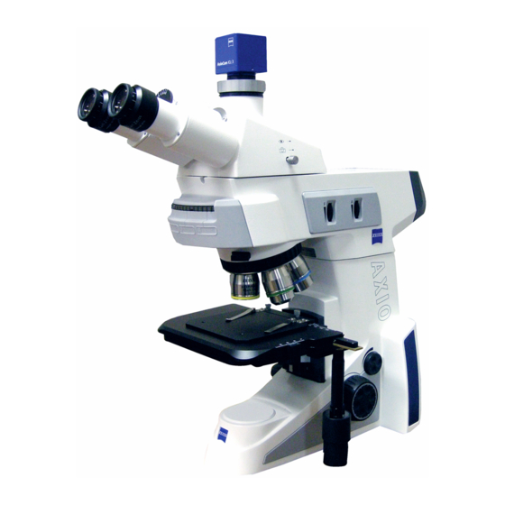
Page 16: System Overview
DESCRIPTION OF THE INSTRUMENT Carl Zeiss System overview Axio Lab.A1 System overview 430037-7144-001 04/2013…
-
Page 17
DESCRIPTION OF THE INSTRUMENT Axio Lab.A1 System overview Carl Zeiss 04/2013 430037-7144-001… -
Page 18
DESCRIPTION OF THE INSTRUMENT Carl Zeiss System overview Axio Lab.A1 430037-7144-001 04/2013… -
Page 19
DESCRIPTION OF THE INSTRUMENT Axio Lab.A1 System overview Carl Zeiss 04/2013 430037-7144-001… -
Page 20
DESCRIPTION OF THE INSTRUMENT Carl Zeiss System overview Axio Lab.A1 430037-7144-001 04/2013… -
Page 21: Technical Data
10 mm to the viewing height of the upper limit for ergo tubes Weight Axio Lab.A1 microscope stand (depending on version and accessories) ……approx. 8 to 20 kg Ambient conditions Shipping (in packaging): Permissible ambient temperature ……………….
-
Page 22
DESCRIPTION OF THE INSTRUMENT Carl Zeiss Technical data Axio Lab.A1 Light sources LED transmitted light Power consumption ………………….max. 3 W Adjustment of light source …………..continuous approx. 0.5 to 12 V Halogen lighting transmitted light Power consumption ………………….max. 35 W Halogen lighting reflected light Power consumption …………………… -
Page 23: Viewing Height And Tube Angle
DESCRIPTION OF THE INSTRUMENT Axio Lab.A1 Technical data Carl Zeiss 2.3.1 Viewing height and tube angle Order No. Binocular tube Viewing Adjustment Viewing angle height* in mm 425522-9000-000 Binocular tube 30°/20 30° — none — 434 / 470 425522-9010-000 Binocular photo tube 30°/20 (50:50) 30°…
-
Page 24: Assignment Of Dust Covers, Intermediate Plate And Base Plate
DESCRIPTION OF THE INSTRUMENT Carl Zeiss Technical data Axio Lab.A1 2.3.2 Assignment of dust covers, intermediate plate and base plate Cat. No. Binocular tube Transmitted Conoscopy Reflected light light 430037-9040-000 430037-9020-000 430037-9000-000 430037-9050-000 430037-9010-000 430037-9030-000 425522-9000-000 Binocular tube Small Small 30°/20 Bio…
-
Page 25
DESCRIPTION OF THE INSTRUMENT Axio Lab.A1 Technical data Carl Zeiss Cat. No. Binocular tube Transmitted Conoscopy Reflected light light 430037-9040-000 430037-9020-000 430037-9000-000 430037-9050-000 430037-9010-000 430037-9030-000 425520-9050-000 Binocular ergo tube 15°/23 Medium Medium Medium (50/50), telescopic, height, Spacer Spacer upright image… -
Page 26: Control And Functional Elements On Microscope
DESCRIPTION OF THE INSTRUMENT Carl Zeiss Control and functional elements on microscope Axio Lab.A1 Control and functional elements on microscope 2.4.1 Stand models Five stand models are available in the delivery program: 1. Transmitted light stand for biomedical applications in brightfield, darkfield and phase contrast 2.
-
Page 27: Fig. 2-1 Axio Lab.a1, Stand Transmitted Light
DESCRIPTION OF THE INSTRUMENT Axio Lab.A1 Control and functional elements on microscope Carl Zeiss Fig. 2-1 Axio Lab.A1, stand transmitted light 04/2013 430037-7144-001…
-
Page 28: Stand For Transmitted Light Polarization
DESCRIPTION OF THE INSTRUMENT Carl Zeiss Control and functional elements on microscope Axio Lab.A1 2.4.3 Stand for transmitted light polarization Key to Fig. 2-2: Basic stand Stage carrier for rotary stages (also suitable for mechanical stages) Light intensity control Focusing drive – fine adjustment (right side, finger wheel) Focusing drive –…
-
Page 29: Fig. 2-2 Axio Lab.a1, Stand Transmitted Light Polarization
DESCRIPTION OF THE INSTRUMENT Axio Lab.A1 Control and functional elements on microscope Carl Zeiss Fig. 2-2 Axio Lab.A1, stand transmitted light polarization 04/2013 430037-7144-001…
-
Page 30: Stand For Transmitted Light And Reflected Light Fluorescence
DESCRIPTION OF THE INSTRUMENT Carl Zeiss Control and functional elements on microscope Axio Lab.A1 2.4.4 Stand for transmitted light and reflected light fluorescence Key to Fig. 2-3: Reflected light intensity control FL/TL switch (FL — reflected light fluorescence; TL — transmitted light)
-
Page 31: Fig. 2-3 Axio Lab.a1, Stand Transmitted And Reflected Light Fluorescence
DESCRIPTION OF THE INSTRUMENT Axio Lab.A1 Control and functional elements on microscope Carl Zeiss Fig. 2-3 Axio Lab.A1, stand transmitted and reflected light fluorescence 04/2013 430037-7144-001…
-
Page 32: Stand For Reflected Light
DESCRIPTION OF THE INSTRUMENT Carl Zeiss Control and functional elements on microscope Axio Lab.A1 2.4.5 Stand for reflected light Key to Fig. 2-4: Reflected light illumination Luminous-field diaphragm (centered) Aperture diaphragm (centered) Basic stand Nosepiece 5x H HD Stage carrier for mechanical stages Light intensity control Focusing drive –…
-
Page 33: Fig. 2-4 Axio Lab.a1, Stand Reflected Light
DESCRIPTION OF THE INSTRUMENT Axio Lab.A1 Control and functional elements on microscope Carl Zeiss Fig. 2-4 Axio Lab.A1, stand reflected light 04/2013 430037-7144-001…
-
Page 34: Stand For Transmitted Light Conoscopy
DESCRIPTION OF THE INSTRUMENT Carl Zeiss Control and functional elements on microscope Axio Lab.A1 2.4.6 Stand for transmitted light conoscopy Key to Fig. 2-5: Rotary knob A: Swiveling analyzer in/out Rotary knob BL: Swiveling Bertrand lens in/out Basic stand Nosepiece 4x H Pol (3 eyes centering, 1 eye fixed)
-
Page 35: Fig. 2-5 Axio Lab.a1, Stand Transmitted Light Conoscopy
DESCRIPTION OF THE INSTRUMENT Axio Lab.A1 Control and functional elements on microscope Carl Zeiss Fig. 2-5 Axio Lab.A1, stand transmitted light conoscopy 04/2013 430037-7144-001…
-
Page 36: Ergo Stands With Tüv Certificate «Ergonomically Tested
Mechanical stage 75×30 ergonomic with stationary drive Stand for transmitted light and reflected light fluorescence Fig. 2-6 Axio Lab.A1 ergonomic stand with TÜV certificate «Ergonomically tested» Further information on the ergonomically correct setting of the microscope and its ergonomic operation can be found in Section 3.5.
-
Page 37: Control And Functional Elements On Optional Components
DESCRIPTION OF THE INSTRUMENT Axio Lab.A1 Control and functional elements on optional components Carl Zeiss Control and functional elements on optional components 2.5.1 Tubes/photo tubes The appropriate adapters for reflex cameras, microscope cameras and video cameras may be plugged into the camera port (Fig. 2-7/1 or Fig.
-
Page 38: Fig. 2-9 Setting The Viewing Height On The Binocular Tube
50:50 CAUTION The binocular ergo tube/ergo photo tube 8-38°/20 may only be used on the Axio Lab.A1 with the base plate (430037-9100-000) installed, as the microscope is otherwise liable to tip over, resulting in damage to the instrument or injury to the user.
-
Page 39: Fig. 2-11 Binocular Ergo Tube 8-33°/20 With Vertical Adjustment 50 Mm
Fig. 2-11 Binocular ergo tube 8-33°/20 with 8-33°/22 may only be used on the vertical adjustment 50 mm Axio Lab.A1 with the base plate (430037-9100-000) installed, as the microscope is otherwise liable to tip over, resulting in damage to the instrument or injury to the user.
-
Page 40: Fig. 2-12 Binocular Ergo Photo Tube 20°/23 With Vertical Adjustment
15°/23, each with continuous vertical adjustment These ergo photo tubes are designed for field of view of 23. For use on the Axio Lab.A1 they are recommended for max. field of view of 22. The viewing angle is 20° or 15°.
-
Page 41: Microscope Stages
DESCRIPTION OF THE INSTRUMENT Axio Lab.A1 Control and functional elements on optional components Carl Zeiss 2.5.2 Microscope stages Mechanical stage 75×30 R or L or mechanical stage 75×30 R ergonomic with stationary drive Mechanical stage (Fig. 2-14/7) for seating, positioning and securing specimens with specimen holder.
-
Page 42: Fig. 2-17 Rotary Stage Pol
DESCRIPTION OF THE INSTRUMENT Carl Zeiss Control and functional elements on optional components Axio Lab.A1 Rotary stage Pol 360° with lock Rotary stage Pol (Fig. 2-17) for seating, positioning and securing specimens with specimen guide (Fig. 2-17/5) and specimen holder (Fig. 2-17/7).
-
Page 43: Condensers
DESCRIPTION OF THE INSTRUMENT Axio Lab.A1 Control and functional elements on optional components Carl Zeiss 2.5.3 Condensers Condenser 0.9/1.25 H, D, Ph1, Ph2, Ph3 Condenser 0.9/1.25 H (Fig. 2-19/1) with aperture diaphragm (Fig. 2-19/4) with modulator disk (Fig. 2-19/3) for:…
-
Page 44: Fig. 2-21 Overview Fixture
DESCRIPTION OF THE INSTRUMENT Carl Zeiss Control and functional elements on optional components Axio Lab.A1 Overview fixture 2.5x–4x The overview fixture is for full display field illumination when using an objective with a weak magnification factor (2.5x–4x) in combination with the Abbe condenser 0.0/1.25 H (424227-9000-…
-
Page 45: Reflector Turret 4X
DESCRIPTION OF THE INSTRUMENT Axio Lab.A1 Control and functional elements on optional components Carl Zeiss 2.5.4 Reflector turret 4x The 4x reflector turret is equipped with reflector positions P&C. The reflector position is adjusted by turning the knurled ring (Fig. 2-23/1).
-
Page 46: Start-Up
Axio Lab.A1 START-UP The Axio Lab.A1 microscope can be independently installed, converted and started up by the customer. On request, the microscope can also be installed or converted by Zeiss Service at an extra charge. Before installing and starting-up the microscope, be sure to carefully read the Notes on instrument safety (see Section 1.1).
-
Page 47: Mounting Base Plate For Use Of Larger Tubes
3.1.2 Mounting base plate for use of larger tubes The base plate must be mounted on Axio Lab.A1 stands in order to increase stability during operation for the majority of tubes/photo tubes/ergo tubes, or this is at least recommended. Please refer to the corresponding notes in the system overview, Section2.2.
-
Page 48: Attaching The Binocular Tube/Photo Tube
START-UP Carl Zeiss Installing standard components Axio Lab.A1 3.1.3 Attaching the binocular tube/photo tube All binocular tubes listed in the system overview (refer to Section 2.2) can be mounted on the microscope stand as described below. Regardless of the stand type and tube used, in some cases an intermediate plate must also be mounted (see Section 2.2).
-
Page 49: Installing Eyepieces Or Auxiliary Microscope Or Diopter
START-UP Axio Lab.A1 Installing standard components Carl Zeiss 3.1.4 Installing eyepieces or auxiliary microscope or diopter Remove both dust caps (Fig. 3-6/1 and 5) from the binocular tube. Remove the two eyepieces (Fig. 3-6/2) from their cases and insert them into the binocular tube as far as they will go.
-
Page 50: Screwing In Objectives
START-UP Carl Zeiss Installing standard components Axio Lab.A1 Inserting reversible eyecups The eyepieces have rubber protection rings to avoid scratches on the eyeglasses. These may be replaced by reversible eyecups as desired. For this purpose remove the eyeglass protection rings (Fig. 3-7/2) from the eyepieces and mount the eyecups (Fig.
-
Page 51: Fitting And Removing Push&Click Modules In The Reflector Turret
START-UP Axio Lab.A1 Installing standard components Carl Zeiss 3.1.6 Fitting and removing push&click modules in the reflector turret The reflector turret 4x stand transmitted and reflected light (BioMed) and the reflected light stand (Material) is firmly installed. The modules must be inserted and removed from the front after removing the cover cap.
-
Page 52: Mounting A Mechanical Stage
Installing standard components Axio Lab.A1 3.1.7 Mounting a mechanical stage Axio Lab.A1 stands are fitted with the respective mechanical stage at the factory according to customer requirements. The friction torque of the drive knobs is set at an average value at the factory.
-
Page 53: Fig. 3-11 Setting Friction Torque
START-UP Axio Lab.A1 Installing standard components Carl Zeiss 3.1.7.4 Setting friction torque of drive knobs for X/Y adjustment of the mechanical stage (1) X drive Push drive knob for X adjustment (Fig. 3-11/4) right to the bottom. Remove supplied adjusting pin (Fig. 3-11/5)
-
Page 54: Mounting Rotary Stage Pol
START-UP Carl Zeiss Installing standard components Axio Lab.A1 3.1.8 Mounting rotary stage Pol 3.1.8.1 Removing rotary stage pole Loosen screw cap (Fig. 3-12/6) from the spring housing (about three rotations). Press rotary stage Pol (Fig. 3-12/4) to the front against spring-loaded pin (Fig. 3-12/7), lift it off the stage carrier (Fig.
-
Page 55: Fig. 3-13 Centring Rotary Stage Pol
START-UP Axio Lab.A1 Installing standard components Carl Zeiss 3.1.8.4 Removing the stage clips and mounting the detachable specimen guide Pol Remove the stage clips (Fig. 3-12/9) from the rotary stage Pol. Insert the specimen guide Pol (Fig. 3-12/2) with the two cylindrical pins on the underside into the holes provided (Fig.
-
Page 56: Fig. 3-14 Centering Objectives
START-UP Carl Zeiss Installing standard components Axio Lab.A1 3.1.8.6 Centring objectives polarization stand The nosepiece 4x Pol is equipped with one fixed and three centerable objective positions. Stage centering of the non-centering objective mount is necessary to ensure that a specimen feature located in the center of the field of view does not drift out while rotating the stage.
-
Page 57: Attaching Condenser
START-UP Axio Lab.A1 Installing standard components Carl Zeiss 3.1.9 Attaching condenser Move the stage carrier with focusing drive to the higher stop position. CAUTION The objectives should not collide with other parts. Swivel out front lens (if shiftable) on condenser using lever (Fig.
-
Page 58: Installing Or Replacing 35 W Halogen Bulb Or 3 W White Light Led Lamp
Installing or replacing 35 W halogen bulb or 3 W white light LED lamp If desired, Axio Lab.A1 transmitted light stands can be equipped with a 3 W white light LED lamp with spectrum daylight or warm light. To insert or replace the halogen/LED lamp, proceed…
-
Page 59
START-UP Axio Lab.A1 Installing standard components Carl Zeiss Check that the lighting unit is seated correctly and insert the plug (Fig. 3-19/2) onto the pins of the lighting unit (Fig. 3-19/1). Ensure that it engages properly to avoid bending the pins. -
Page 60: Installing Or Changing The 12 V 50 W Halogen Lamp
3.1.11 Installing or changing the 12 V 50 W halogen lamp Each Axio Lab.A1 reflected light stand is equipped with a 12 V 50 W halogen lamp. To insert or replace a halogen lamp, proceed as follows: Switch off the microscope, remove the power cord on the microscope and allow it to cool down at least 15 min.
-
Page 61: Installing Or Replacing Led Modules
Carl Zeiss 3.1.12 Installing or replacing LED modules Axio Lab.A1 transmitted/reflected light stands may be equipped for transmitted light applications with a 35 W halogen lamp or an 3 W LED lamp (see Section 3.1.10) and for reflected light fluoresce applications with up to two LED modules from the delivery program (see also Section 2.2).
-
Page 62: Mounting Optional Components
3.2.1 Mounting the light intensive co-observer unit The light-intensive co-observer unit is mounted on the Axio Lab.A1 with a main observer and one or two co-observers in accordance with the separate instructions for use for multi-discussion facilities (Order No. 425145-7144-001).
-
Page 63: Mounting And Centering The Overview Fixture
START-UP Axio Lab.A1 Mounting optional components Carl Zeiss 3.2.3 Mounting and centering the overview fixture Lift the condenser carrier together with its drive knob upwards as far as it will go. Remove the polarizer or filter holder from the condenser carrier as applicable.
-
Page 64: Inserting Modulator Disk In Condenser 0.9 H Pol
START-UP Carl Zeiss Mounting optional components Axio Lab.A1 3.2.4 Inserting modulator disk condenser 0.9 H Pol Remove the condenser (Fig. 3-28/1) from the condenser carrier (see Section 3.1.9). If the condenser carrier cannot be lowered sufficiently, e.g. when the overview fixture is…
-
Page 65: Connecting To The Power Supply
Carl Zeiss Connecting to the power supply In all stand models the power supply of the Axio Lab.A1 is located in the rear side of the instrument. Connect microscope (Fig. 3-29/1) to the mains power supply via a power cord and mains socket.
-
Page 66: Basic Setting Of The Microscope From An Ergonomic Point Of View
The following sections of this user manual contain advice for the correct basic setting of the Axio Lab.A1, particularly from an ergonomic point of view. They also include notes on ergonomic configuration of the overall microscope workstation.
-
Page 67: Tüv Certificate Id:0000025994 «Ergonomically Tested
3.5.3 Ergonomic configuration of the microscope workstation In addition to the use of an ergonomically designed microscope, e.g. the Axio Lab.A1, the microscope workstation must exhibit further ergonomically relevant aspects in terms of lighting conditions, air temperature, humidity, general workplace configuration, height-adjustable chair and table surface. These aspects are described in more detail in the following;…
-
Page 68: Ergonomic Adjustment Of The Microscope
Carl Zeiss Basic setting of the microscope from an ergonomic point of view Axio Lab.A1 The microscope workstation must be separate from the general laboratory area to enable uninterrupted work, in particular for medium and long periods of work. The workstation must be free of dust and acidic…
-
Page 69
9040-000), the eyepiece viewing height and angle are continuously variable to cover the range from the 5th percentile female to the 95th percentile male. When using other ergo tubes from the Axio Lab.A1 program the coverage of the setting range is somewhat smaller. -
Page 70: Setting Interpupillary Distance On The Binocular Tube
(Fig. 3-35/B). This individual height adjustment in two stages (upper and lower position) is basically possible with all tubes of the Axio Lab.A1 program. The viewing height difference thus achieved depends on the selected interpupillary distance and the tube viewing angle, which may be stationary or variable, depending on the model.
-
Page 71: Adjusting For Ametropia When Using Eyepiece Reticles
START-UP Axio Lab.A1 Basic setting of the microscope from an ergonomic point of view Carl Zeiss 3.5.7 Adjusting for ametropia when using eyepiece reticles The prerequisite for correct use of an eyepiece reticle is two adjustable eyepieces to compensate for different degrees of ametropia of the user.
-
Page 72: Operation
Section 4.1.1 (3) «Setting transmitted light brightfield according to KÖHLER». (2) Instrumentation for transmitted light brightfield The equipment of every Axio Lab.A1 microscope, except the stand for reflected light, allows the transmitted light brightfield method to be used.
-
Page 73
OPERATION Axio Lab.A1 Lighting and contrasting method in transmitted light Carl Zeiss Close luminous-field diaphragm (Fig. 4-1/5) until it is visible (even if not in focus) in the field of view (Fig. 4-1/A). Turn the vertical control of the condenser drive… -
Page 74
OPERATION Carl Zeiss Lighting and contrasting method in transmitted light Axio Lab.A1 (4) Setting the height stop on the condenser carrier Loosen the fastening screw (Fig. 4-2/1) of the height stop using SW 3 ball-headed screwdriver. Use focusing drive to focus on the specimen. -
Page 75: Adjusting The Transmitted Light Darkfield According To Köhler
(2) Instrumentation All Axio Lab.A1 microscopes, except stands for reflected light, are suitable for darkfield applications. Condenser with darkfield stop in position D e.g.: Condenser 0.9/1,25 H with modulator disk H, D, Ph 1, Ph 2, Ph 3, Condenser, achrom.-aplan.
-
Page 76: Setting The Transmitted Light Phase Contrast
(2) Instrumentation All Axio Lab.A1 microscopes, except stands for reflected light, are suitable for phase contrast applications. Phase contrast objectives with phase rings Ph 1, Ph 2 or Ph 3 for different average numerical apertures which can also be used in the brightfield.
-
Page 77
OPERATION Axio Lab.A1 Lighting and contrasting method in transmitted light Carl Zeiss (3) Setting transmitted light phase contrast Swivel the phase contrast objective, e.g. labeled Ph 1, into the beam path. On the turret disk of the condenser, swivel in the phase stop to match the phase contrast objective, e.g. -
Page 78: Setting Transmitted Light Polarization
These interference colors can be of the first or any higher order. (2) Instrumentation Polarization methods can be used in the transmitted light on Axio Lab.A1 microscopes for transmitted light polarization and conoscopy. Tension-free objectives…
-
Page 79
OPERATION Axio Lab.A1 Lighting and contrasting method in transmitted light Carl Zeiss (3) Setting the microscope Set the microscope as in the transmitted light brightfield according to KÖHLER (see Section 4.1.1 (3)). Center rotary stage Pol (Fig. 4-5/1) (see Section 3.1.8.5) and objectives (see Section 3.1.8.6). -
Page 80
OPERATION Carl Zeiss Lighting and contrasting method in transmitted light Axio Lab.A1 4.1.4.2 Determination of gout and pseudogout Set the microscope as in the transmitted light brightfield according to KÖHLER (see Section 4.1.1 (3)). Then swivel the polarizer, rigidly fixed to the lambda plate (445226-0000-000) (Fig. 4-5/3) into the beam path. -
Page 81
(2) Instrumentation Eyepiece with crossline reticle Tension-free objectives Rotary stage Pol (Fig. 4-5/1) Polarizer D (rotatable or fixed) Screw-in fixed analyzer slide D or lambda/lambda4 compensator combined with analyzer (in Axio Lab.A1 tubes) Alignment specimen for polarization microscope (453679-0000-000) 04/2013 430037-7144-001… -
Page 82
OPERATION Carl Zeiss Lighting and contrasting method in transmitted light Axio Lab.A1 (3) Setting the microscope Set the microscope as for the transmitted light brightfield (see Section 4.1.1), taking care to ensure the correct interpupillary distance in the binocular tube (see Section 3.5.5). -
Page 83
OPERATION Axio Lab.A1 Lighting and contrasting method in transmitted light Carl Zeiss (4) Conclusions The grayish-white color appearing first in the bright position in the above example (Fig. 4-7/1) corresponds to a path difference of 150 nm according to the Michel-Lévy color chart (Fig. 4-8). -
Page 84
OPERATION Carl Zeiss Lighting and contrasting method in transmitted light Axio Lab.A1 Limit to aperture to a value of about 0.2. Turn the rotary stage Pol until the specimen is almost obliterated, i.e. completely dark, and set the 45° locking position. -
Page 85
Circular polarizer D (no polarizers may be adapted on the condenser) including corresponding /4 plate. Stationery analyzer slide D or screw-in analyzer (in Axio Lab.A1 tubes). (3) Setting the microscope Set the microscope as in the transmitted light brightfield according to KÖHLER (see Section 4.1.1). -
Page 86
OPERATION Carl Zeiss Lighting and contrasting method in transmitted light Axio Lab.A1 Slide 6×20 with /4 plate Lower section of circular polarizer Lever for rotating /4 plate /4 plate in upper part of the circular polarizer Adjustment slits Fig. 4-9 Components for circular polarization contrast An (anisotropic) specimen should not be observed until after the above adjustment. -
Page 87: Setting Transmitted Light Polarization With The Conoscopy Stand
Its main application is the classical mineral microscopy. However, synthetic crystals, industrial minerals and plastics (e.g. films) can also be identified and characterized. (2) Instrumentation Conoscopic viewing is preferably carried out on the Axio Lab.A1 microscope for transmitted light conoscopy. Tension-free objectives; recommended: N-Achroplan 50x/0.8 Pol objective or…
-
Page 88
(Fig. 4-10/4) of the analyzer. Fig. 4-10 Axio Lab.A1 for transmitted light conoscopy CAUTION The movements of rotary knobs A and BL and the respective setting wheels are coupled with one another. -
Page 89
OPERATION Axio Lab.A1 Lighting and contrasting method in transmitted light Carl Zeiss Inserting a compensator (473704-0000-000) or /4 (473714-0000-000) or a wedge compensator 0-4 (000000-1140-663) in the compensator slot with the initial state of the axial figure being as illustrated in Fig. -
Page 90
(mostly with biological specimens) to white, yellow, red and blue appear in this process. These interference colors can be of the first or any higher order. (2) Instrumentation On the Axio Lab.A1 microscope for transmitted light conoscopy: Tension-free objectives Rotary stage Pol… -
Page 91
OPERATION Axio Lab.A1 Lighting and contrasting method in transmitted light Carl Zeiss (3) Setting the microscope Set the microscope as in the transmitted light brightfield according to KÖHLER (see Section 4.1.1 (3)). Center rotary stage Pol (Fig. 4-12/1) (see Section 3.1.8.5) and objectives (see Section 3.1.8.6). -
Page 92
OPERATION Carl Zeiss Lighting and contrasting method in transmitted light Axio Lab.A1 Evaluation: If the crystal needles parallel to the gamma direction are yellow and those perpendicular to the gamma direction are blue, they are monosodium urate crystals (gout). If the crystal needles parallel to the gamma direction are blue and those perpendicular to the gamma direction are yellow, they are calcium pyrophosphate crystals (pseudogout). -
Page 93
OPERATION Axio Lab.A1 Lighting and contrasting method in transmitted light Carl Zeiss (3) Setting the microscope Set the microscope as for the transmitted light brightfield (see Section 4.1.1), taking care to ensure the correct interpupillary distance in the binocular tube (see Section 3.5.5). -
Page 94
OPERATION Carl Zeiss Lighting and contrasting method in transmitted light Axio Lab.A1 (4) Conclusions The grayish-white color appearing first in the bright position in the above example (Fig. 4-14/1) corresponds to a path difference of 150 nm according Michel-Lévy color chart (Fig. -
Page 95
OPERATION Axio Lab.A1 Lighting and contrasting method in transmitted light Carl Zeiss Limit to aperture to a value of about 0.2. Turn the rotary stage Pol until the specimen is almost obliterated, i.e. completely dark. Rotate the stage once (by 45°) so that the specimen is in a diagonal position (bright). -
Page 96
OPERATION Carl Zeiss Lighting and contrasting method in transmitted light Axio Lab.A1 4.1.6.5 Circular polarization contrast with Axio Lab for conoscopy (1) Application Unlike standard polarization contrast, circular polarization contrast does not show any dark (extinction) positions that depend on the angle of rotation (azimuth) of the specimen relative to polarizer or analyzer. -
Page 97
OPERATION Axio Lab.A1 Lighting and contrasting method in transmitted light Carl Zeiss Slide 6×20 with /4 plate Lower section of circular polarizer Lever for rotating /4 plate /4 plate in upper part of the circular polarizer Adjustment slits Fig. 4-16 Components for circular polarization contrast on conoscopy stand An (anisotropic) specimen should not be observed until after the above adjustment. -
Page 98: Setting Transmitted Light Polarization For Conoscopic Observation — Determining The Optical Character Of Crystals
Its main application is the classical mineral microscopy. However, synthetic crystals, industrial minerals and plastics (e.g. films) can also be identified and characterized. (1) Instrumentation Conoscopic viewing is preferably carried out on the Axio Lab.A1 microscope for transmitted light conoscopy. Tension-free objectives; recommended: N-Achroplan 50x/0.8 Pol objective or…
-
Page 99
Place the specimen on the stage and focus on Swivel the analyzer into the beam path (on position) with rotary knob A (Fig. 4-17/2). The Fig. 4-17 Axio Lab.A1 for transmitted light direction of oscillation can be changed using conoscopy the setting wheel (Fig. 4-17/4) of the analyzer. -
Page 100
OPERATION Carl Zeiss Lighting and contrasting method in transmitted light Axio Lab.A1 With optically biaxial crystals, the cross resolves into two dark hyperbola branches (the so-called isogyres) depending on stage rotation, which are surrounded by colored interference patterns depending on the amount of birefringence and specimen thickness (suggestive of the figure «8»). -
Page 101: Lighting And Contrasting Method In Reflected Light
OPERATION Axio Lab.A1 Lighting and contrasting method in reflected light Carl Zeiss Lighting and contrasting method in reflected light 4.2.1 Adjusting the reflected light brightfield according to KÖHLER (1) Application Reflected light brightfield microscopy is the simplest and most common optical microscopy method for examining opaque samples or specimens, e.g.
-
Page 102
Carl Zeiss Lighting and contrasting method in reflected light Axio Lab.A1 For specimens with medium contrast characteristics, set the aperture diaphragm with the knurled wheel (Fig. 4-19/1) to about 2/3 to 4/5 of the exit pupil diameter of the objective. -
Page 103: Adjusting The Reflected Light Darkfield
All these light-scattering details light up brightly in the darkfield, whereas the even surface remains dark. (2) Instrumentation Observations in the reflected light darkfield can only be made on Axio Lab.A1 microscopes for reflected light. Epiplan-Neofluar, EC Epiplan-Neofluar, Epiplan objectives with the additional designation “HD”…
-
Page 104: Adjusting Reflected Light Polarization — Proof Of Bireflexion And Reflexion-Pleochroism
(Antiflex cap) permits the reflections to be eliminated even with «dark» specimen surfaces, which otherwise would be unavoidable. (2) Instrumentation Observations in the reflected light darkfield can only be made on Axio Lab.A1 microscopes for reflected light. Rotary stage Pol Epiplan-Neofluar Pol, EC Epiplan-Neofluar Pol, Epiplan Pol objectives C DIC/DIC/TIC ACR P&C or DIC/Pol ACR P&C or DIC Red I ACR P&C reflector module…
-
Page 105: Adjusting Reflected Light Fluorescence
The spectra of the excitation and the band-elimination filters must match very closely. They must be inserted in a reflector module FL P&C together with the respective dichroic beam splitter. Only powerful LED are supplied as FL excitation light sources in the Axio Lab.A1 program. (2) Instrumentation Observations in reflected light fluorescence can only be made on Axio Lab.A1 microscopes for reflected…
-
Page 106
OPERATION Carl Zeiss Lighting and contrasting method in reflected light Axio Lab.A1 On the reflector turret (Fig. 4-20/9), select reflector module FL P&C with the desired fluorescence filter combination (depending on excitation mode) and switch on. Use the push-pull rod (Fig. 4-20/1) to swivel the desired LED (1 or 2) into the beam path. -
Page 107: Care, Fuse Replacement And Service
Carl Zeiss CARE, FUSE REPLACEMENT AND SERVICE Instrument care The only care required for the Axio Lab.A1 is as follows: Switch the device off each time after use and apply the protective cover (protects against dust and moisture). Do not set the instrument up in a moist environment (max. humidity < 75 %).
-
Page 108: Instrument Maintenance
CARE, FUSE REPLACEMENT AND SERVICE Carl Zeiss Instrument maintenance Axio Lab.A1 Instrument maintenance 5.2.1 Checking the instrument Ensure that the prescribed line voltages are observed. Check the power cable and the plug for possible damage. If any damage is observed, turn the instrument off and secure immediately. Call in a qualified professional to remedy the problem.
-
Page 109: Troubleshooting
CARE, FUSE REPLACEMENT AND SERVICE Axio Lab.A1 Troubleshooting Carl Zeiss Troubleshooting Problem Cause Troubleshooting Shadows or inhomogeneous The vis/fot push-pull rod/shift knob on Move the vis/fot push-pull rod/shift image brightness in the field of the photo tube is not in the correct knob to the correct position (end view;…
-
Page 110
CARE, FUSE REPLACEMENT AND SERVICE Carl Zeiss Troubleshooting Axio Lab.A1 Problem Cause Troubleshooting Asymmetric image sharpness, e.g. Condenser is not correctly adjusted. Adjust the condenser correctly; one side is sharp, one is side see p. 72 ff. blurred. Nosepiece is not engaged in its Engage the nosepiece in its locking locking position. -
Page 111
CARE, FUSE REPLACEMENT AND SERVICE Axio Lab.A1 Troubleshooting Carl Zeiss Problem Cause Troubleshooting LED/halogen lamp does not light Power plug is not plugged into the Insert the plug into the mains outlet. up although the switch in the on mains outlet. -
Page 112: Service
Service Repairs of mechanical, optical or electronic components inside the instrument and electrical components of Axio Lab.A1 microscopes may only be performed by Carl Zeiss service staff or specially authorized personnel. To ensure optimum setting and trouble-free function of your microscope over a longer period of time, we recommend that you enter into a service/maintenance agreement with Carl Zeiss.
-
Page 113: Annex
ANNEX Axio Lab.A1 List of abbreviations Carl Zeiss ANNEX List of abbreviations Alternating current Bertrand lens Suitability for spectacle wearers Canadian Standards Association Frame glass thickness Darkfield Diameter (e.g. filter) Differential Interference Contrast Deutsches Institut für Normung (German Standards Institute)
-
Page 114: Index
ANNEX Carl Zeiss Index Axio Lab.A1 Index Page Ametropia ……………………….71 Analyzer………………….34, 78, 85, 90, 91, 93, 96 Analyzer slider ……………………. 79, 80, 82 Aperture diaphragm …………………… 32, 43, 73 Auxiliary microscope ……………………..49 Base plate ……………………….. 30, 47 Basic setting ……………………….66 Bertrand lens ………………………
-
Page 115
ANNEX Axio Lab.A1 Index Carl Zeiss Ergo photo tube ……………………..38 Ergo tube ……………………..36, 38, 39, 40 Ergonomics ……………………..12, 36 Eyecups ………………………… 50 Eyeglass protection ring ……………………50 Eyepiece reticle ……………………..49, 71 Eyepieces ………………….26, 28, 30, 32, 34, 49 Filter holder ………………………. -
Page 116
ANNEX Carl Zeiss Index Axio Lab.A1 Microscope adjustment ……………………68 Microscope stages ……………………..41 Modulator disk ……………………….64 Nosepiece ………………. 26, 28, 30, 32, 34, 45, 50, 56, 72 Objective centering ……………………..56 Objectives ……………………….. 50, 55 ON/OFF switch ………………….26, 28, 30, 32, 34 Operation ……………………….72… -
Page 117
ANNEX Axio Lab.A1 Index Carl Zeiss Technical data ………………………. 21 Toggle switch FL/TL ……………………..30 Tool …………………………46 Tool flap ……………………26, 28, 30, 32, 34 Transmitted light …………….26, 28, 30, 34, 72, 75, 76, 78, 87, 98 Transmitted light brightfield …………………… 72 Transmitted light illumination …………………. -
Page 118: Industrial Property Rights
ANNEX Carl Zeiss Industrial property rights Axio Lab.A1 Industrial property rights Instruments, instrument components or methods described in this manual are protected by the following patents: see label on microscope stand 430037-7144-001 04/2013…
(Ocr-Read Summary of Contents of some pages of the Ryf Axio Lab.A1 Document (Main Content), UPD: 23 July 2023)
-
59, Ryf Axio Lab.A1 START-UP Axio Lab.A1 Installing standard components Carl Zeiss 04/2013 430037-7144-001 59 x Check that the lighting unit is seated correctly and insert the plug (Fig. 3-19/2) onto the pins of the lighting unit (Fig. 3-19/1). Ensure that it engages properly to avoid bending the pins. x Insert the cable of the lamp plug into the stand so that it is not damaged when the cover is mounted. x Insert the lower edge of the cover (Fig. 3-16/2) into…
-
78, OPERATION Carl Zeiss Lighting and contrasting method in transmitted light Axio Lab.A1 78 430037-7144-001 04/2013 4.1.4 Setting transmitted light polarization 4.1.4.1 Detecting birefringence (1) Application The transmitted light polarization method is used for specimens which change the state of polarization of light. These specimens, such as crystals, minerals or polymers, are referred t…
-
72, OPERATION Carl Zeiss Lighting and contrasting method in transmitted light Axio Lab.A1 72 430037-7144-001 04/2013 4 OPERATION 4.1 Lighting and contrasting method in transmitted light 4.1.1 Adjusting the transmitted light brightfield according to KÖHLER (1) General principle Transmitted light brightfield microscopy is the most common optical microscopy method, as high- contrast or colored specimens (e.g. blood smears) can b…
-
71, START-UP Axio Lab.A1 Basic setting of the microscope from an ergonomic point of view Carl Zeiss 04/2013 430037-7144-001 71 3.5.7 Adjusting for ametropia when using eyepiece reticles The prerequisite for correct use of an eyepiece reticle is two adjustable eyepieces to compensate for different degrees of ametropia of the user. x Focus on the line figure of the eyepiece reticle with the focusable eye lens of …
-
102, OPERATION Carl Zeiss Lighting and contrasting method in reflected light Axio Lab.A1 102 430037-7144-001 04/2013 x For specimens with medium contrast characteristics, set the aperture diaphragm with the knurled wheel (Fig. 4-19/1) to about 2/3 to 4/5 of the exit pupil diameter of the objective. In most applications, this aperture diaphragm setting provides optimum contrast at almost ideal resolution, and is therefore the best compromise for the human eye. x …
-
15, DESCRIPTION OF THE INSTRUMENT Axio Lab.A1 Intended use Carl Zeiss 04/2013 430037-7144-001 15 The ergonomic design elements of the Axio Lab.1 are: Vertically adjustable, swivel-type and swivel/vertically adjustable ergo tubes Skin-friendly surfaces on binocular section of the tubes, control elements and stand Ergo table with fixed stage drive Vertical and friction adjustable stage drives Optional use o…
-
30, Ryf Axio Lab.A1 DESCRIPTION OF THE INSTRUMENT Carl Zeiss Control and functional elements on microscope Axio Lab.A1 30 430037-7144-001 04/2013 2.4.4 Stand for transmitted light and reflected light fluorescence Key to Fig. 2-3: 1 Reflected light intensity control 2 FL/TL switch (FL — reflected light fluorescence; TL — transmitted light) 3 Push-pull rod for switching between LED 1 and LED 2 4 Cover flap for LED reflected light illumination in top part of s…
-
93, OPERATION Axio Lab.A1 Lighting and contrasting method in transmitted light Carl Zeiss 04/2013 430037-7144-001 93 (3) Setting the microscope x Set the microscope as for the transmitted light brightfield (see Section 4.1.1), taking care to ensure the correct interpupillary distance in the binocular tube (see Section 3.5.5). x Center rotary stage Pol (Fig. 4-5/1) and objectives (see Sections 3.1.8.5 and 3.1.8.6).…
-
37, DESCRIPTION OF THE INSTRUMENT Axio Lab.A1 Control and functional elements on optional components Carl Zeiss 04/2013 430037-7144-001 37 2.5 Control and functional elements on optional components 2.5.1 Tubes/photo tubes The appropriate adapters for reflex cameras, microscope cameras and video cameras may be plugged into the camera port (Fig. 2-7/1 or Fig. 2-8/1) of the binocular photo tubes. Bi…
-
43, DESCRIPTION OF THE INSTRUMENT Axio Lab.A1 Control and functional elements on optional components Carl Zeiss 04/2013 430037-7144-001 43 2.5.3 Condensers Condenser 0.9/1.25 H, D, Ph1, Ph2, Ph3 Condenser 0.9/1.25 H (Fig. 2-19/1) with aperture diaphragm (Fig. 2-19/4) with modulator disk (Fig. 2-19/3) for: Brightfield (H) Darkfield (D) Phase contrast Ph 1, Ph 2, Ph 3 Position adjustment of modulator disk by turning knurled ring (Fig. 2-19/2). This cond…
-
64, Ryf Axio Lab.A1 START-UP Carl Zeiss Mounting optional components Axio Lab.A1 64 430037-7144-001 04/2013 3.2.4 Inserting modulator disk in condenser 0.9 H Pol x Remove the condenser (Fig. 3-28/1) from the condenser carrier (see Section 3.1.9). If the condenser carrier cannot be lowered sufficiently, e.g. when the overview fixture is fitted, the latter must be detached to enable the condenser to be pushed down as far…
-
87, OPERATION Axio Lab.A1 Lighting and contrasting method in transmitted light Carl Zeiss 04/2013 430037-7144-001 87 4.1.5 Setting transmitted light polarization with the conoscopy stand 4.1.6 Determining the optical character of crystals For the classification (and thus identification) of crystalline material – instead of the observation of the specimen itself – the analysis of an interference image in the objective pupil provides the more valuabl…
-
85, OPERATION Axio Lab.A1 Lighting and contrasting method in transmitted light Carl Zeiss 04/2013 430037-7144-001 85 4.1.4.5 Circular polarization contrast (1) Application Unlike standard polarization contrast, circular polarization contrast does not show any dark (extinction) positions that depend on the angle of rotation (azimuth) of the specimen relative to polarizer or analyzer. …
-
18, DESCRIPTION OF THE INSTRUMENT Carl Zeiss System overview Axio Lab.A1 18 430037-7144-001 04/2013
… -
29, DESCRIPTION OF THE INSTRUMENT Axio Lab.A1 Control and functional elements on microscope Carl Zeiss 04/2013 430037-7144-001 29 Fig. 2-2 Axio Lab.A1, stand transmitted light polarization
… -
49, START-UP Axio Lab.A1 Installing standard components Carl Zeiss 04/2013 430037-7144-001 49 3.1.4 Installing eyepieces or auxiliary microscope or diopter x Remove both dust caps (Fig. 3-6/1 and 5) from the binocular tube. x Remove the two eyepieces (Fig. 3-6/2) from their cases and insert them into the binocular tube as far as they will go. Before inserting Pol eyepieces with tubes without upright reticle, the orientation screw…
-
Page 2
Carl Zeiss Copyright / Trade Marks Axio Lab.A1 Knowledge of this manual is essential for the operation of the instrument. Please familiarize yourself with the contents of this manual and pay special attention to instructions concerning safe operation of the instrument. -
Page 3: Table Of Contents
Axio Lab.A1 Contents / List of Illustrations Carl Zeiss CONTENTS Page INTRODUCTION ………………..7 Notes on instrument safety ………………7 Notes on ergonomics of the microscope …………..12 Notes on warranty …………………. 13 DESCRIPTION OF THE INSTRUMENT …………..14 Intended use …………………… 14 System overview ………………….
-
Page 4
Carl Zeiss Contents / List of Illustrations Axio Lab.A1 Mounting optional components …………….62 3.2.1 Mounting the light intensive co-observer unit …………..62 3.2.2 Mounting polarizer D or filter holder …………….62 3.2.3 Mounting and centering the overview fixture …………..63 3.2.4… -
Page 5
«RADIATION» and «LED APERTURE» warning labels on Axio Lab.A1 for transmitted and reflected light fluorescence ………………10 Fig. 1-2 «Hot surface below» warning label on Axio Lab.A1 for reflected light …….. 11 Fig. 2-1 Axio Lab.A1, stand transmitted light …………….. 27 Fig. -
Page 6
Schematic diagram of the color charts according to Michel-Lévy ……… 83 Fig. 4-9 Components for circular polarization contrast …………..86 Fig. 4-10 Axio Lab.A1 for transmitted light conoscopy …………..88 Fig. 4-11 Determining optical character ……………….. 89 Fig. 4-12 Components for transmitted light polarization on conoscopy stand ……..91 Fig. -
Page 7: Introduction
Carl Zeiss INTRODUCTION Notes on instrument safety Axio Lab.A1 microscopes have been designed, produced and tested in compliance with DIN EN 61010-1 (IEC 61010-1) and IEC 61010-2-101 safety requirements for electrical measuring, control and laboratory instruments. These instruments meet the requirements of EC Directive IVDD 98/79/EC (In Vitro Diagnostic); they carry mark.
-
Page 8
Carl Zeiss Microscopy Service to repair the instrument. Axio Lab.A1 microscopes are equipped with a power supply unit incorporated in the stand, which allows line voltages ranging from 100 V to 240 V ±10 % (50/60 Hz) to be used without requiring any change of voltage on the unit. -
Page 9
INTRODUCTION Axio Lab.A1 Notes on instrument safety Carl Zeiss LED Risk Group 2 to IEC 62471, LED radiation will be emitted. Never look into the LED beam of the illuminating device – either with or without optical instruments. Failure to observe this precaution may results in eye injuries! Combustible and easily inflammable materials should not be held close to the light beam. -
Page 10: Fig. 1-1 «Radiation» And «Led Aperture» Warning Labels On Axio Lab.a1 For Transmitted And Reflected Light Fluorescence
Notes on instrument safety Axio Lab.A1 Warning labels on Axio Lab.A1 stands Warning label: Hot surface! Affixed to all stands with transmitted light illumination. Fig. 1-1 «RADIATION» and «LED APERTURE» warning labels on Axio Lab.A1 for transmitted and reflected light fluorescence 430037-7144-001 04/2013…
-
Page 11: Fig. 1-2 «Hot Surface Below» Warning Label On Axio Lab.a1 For Reflected Light
INTRODUCTION Axio Lab.A1 Notes on instrument safety Carl Zeiss Fig. 1-2 «Hot surface below» warning label on Axio Lab.A1 for reflected light 04/2013 430037-7144-001…
-
Page 12: Notes On Ergonomics Of The Microscope
This first light microscope worldwide is available with a special ergonomic configuration and bears TÜV certificate ID:0000025994 «Ergonomically tested». Particularly laboratory microscopes in the Axio Lab.A1 device class are used continuously for many routine applications (e.g. haematological, histological and cytological examinations) over a period of several hours.
-
Page 13: Notes On Warranty
For a further explanation of TÜV certificate of ergonomics and basic ergonomic setting and operation of the Axio Lab.A1 microscope please refer to Section 3.5. Notes on warranty The manufacturer guarantees that the instrument has no material or production defects when delivered.
-
Page 14: Description Of The Instrument
The binocular photo tubes and suitable adapters permit one microscope camera, one reflex camera or one digital/video camera to be attached for documentation purposes. The Axio Lab.A1 was specially developed and designed for ergonomic use in lengthy routine applications, e.g. haematological, histological and cytological laboratory examinations.
-
Page 15
DESCRIPTION OF THE INSTRUMENT Axio Lab.A1 Intended use Carl Zeiss The ergonomic design elements of the Axio Lab.1 are: Vertically adjustable, swivel-type and swivel/vertically adjustable ergo tubes Skin-friendly surfaces on binocular section of the tubes, control elements and stand Ergo table with fixed stage drive… -
Page 16: System Overview
DESCRIPTION OF THE INSTRUMENT Carl Zeiss System overview Axio Lab.A1 System overview 430037-7144-001 04/2013…
-
Page 17
DESCRIPTION OF THE INSTRUMENT Axio Lab.A1 System overview Carl Zeiss 04/2013 430037-7144-001… -
Page 18
DESCRIPTION OF THE INSTRUMENT Carl Zeiss System overview Axio Lab.A1 430037-7144-001 04/2013… -
Page 19
DESCRIPTION OF THE INSTRUMENT Axio Lab.A1 System overview Carl Zeiss 04/2013 430037-7144-001… -
Page 20
DESCRIPTION OF THE INSTRUMENT Carl Zeiss System overview Axio Lab.A1 430037-7144-001 04/2013… -
Page 21: Technical Data
10 mm to the viewing height of the upper limit for ergo tubes Weight Axio Lab.A1 microscope stand (depending on version and accessories) ……approx. 8 to 20 kg Ambient conditions Shipping (in packaging): Permissible ambient temperature ……………….
-
Page 22
DESCRIPTION OF THE INSTRUMENT Carl Zeiss Technical data Axio Lab.A1 Light sources LED transmitted light Power consumption ………………….max. 3 W Adjustment of light source …………..continuous approx. 0.5 to 12 V Halogen lighting transmitted light Power consumption ………………….max. 35 W Halogen lighting reflected light Power consumption …………………… -
Page 23: Viewing Height And Tube Angle
DESCRIPTION OF THE INSTRUMENT Axio Lab.A1 Technical data Carl Zeiss 2.3.1 Viewing height and tube angle Order No. Binocular tube Viewing Adjustment Viewing angle height* in mm 425522-9000-000 Binocular tube 30°/20 30° — none — 434 / 470 425522-9010-000 Binocular photo tube 30°/20 (50:50) 30°…
-
Page 24: Assignment Of Dust Covers, Intermediate Plate And Base Plate
DESCRIPTION OF THE INSTRUMENT Carl Zeiss Technical data Axio Lab.A1 2.3.2 Assignment of dust covers, intermediate plate and base plate Cat. No. Binocular tube Transmitted Conoscopy Reflected light light 430037-9040-000 430037-9020-000 430037-9000-000 430037-9050-000 430037-9010-000 430037-9030-000 425522-9000-000 Binocular tube Small Small 30°/20 Bio…
-
Page 25
DESCRIPTION OF THE INSTRUMENT Axio Lab.A1 Technical data Carl Zeiss Cat. No. Binocular tube Transmitted Conoscopy Reflected light light 430037-9040-000 430037-9020-000 430037-9000-000 430037-9050-000 430037-9010-000 430037-9030-000 425520-9050-000 Binocular ergo tube 15°/23 Medium Medium Medium (50/50), telescopic, height, Spacer Spacer upright image… -
Page 26: Control And Functional Elements On Microscope
DESCRIPTION OF THE INSTRUMENT Carl Zeiss Control and functional elements on microscope Axio Lab.A1 Control and functional elements on microscope 2.4.1 Stand models Five stand models are available in the delivery program: 1. Transmitted light stand for biomedical applications in brightfield, darkfield and phase contrast 2.
-
Page 27: Fig. 2-1 Axio Lab.a1, Stand Transmitted Light
DESCRIPTION OF THE INSTRUMENT Axio Lab.A1 Control and functional elements on microscope Carl Zeiss Fig. 2-1 Axio Lab.A1, stand transmitted light 04/2013 430037-7144-001…
-
Page 28: Stand For Transmitted Light Polarization
DESCRIPTION OF THE INSTRUMENT Carl Zeiss Control and functional elements on microscope Axio Lab.A1 2.4.3 Stand for transmitted light polarization Key to Fig. 2-2: Basic stand Stage carrier for rotary stages (also suitable for mechanical stages) Light intensity control Focusing drive – fine adjustment (right side, finger wheel) Focusing drive –…
-
Page 29: Fig. 2-2 Axio Lab.a1, Stand Transmitted Light Polarization
DESCRIPTION OF THE INSTRUMENT Axio Lab.A1 Control and functional elements on microscope Carl Zeiss Fig. 2-2 Axio Lab.A1, stand transmitted light polarization 04/2013 430037-7144-001…
-
Page 30: Stand For Transmitted Light And Reflected Light Fluorescence
DESCRIPTION OF THE INSTRUMENT Carl Zeiss Control and functional elements on microscope Axio Lab.A1 2.4.4 Stand for transmitted light and reflected light fluorescence Key to Fig. 2-3: Reflected light intensity control FL/TL switch (FL — reflected light fluorescence; TL — transmitted light)
-
Page 31: Fig. 2-3 Axio Lab.a1, Stand Transmitted And Reflected Light Fluorescence
DESCRIPTION OF THE INSTRUMENT Axio Lab.A1 Control and functional elements on microscope Carl Zeiss Fig. 2-3 Axio Lab.A1, stand transmitted and reflected light fluorescence 04/2013 430037-7144-001…
-
Page 32: Stand For Reflected Light
DESCRIPTION OF THE INSTRUMENT Carl Zeiss Control and functional elements on microscope Axio Lab.A1 2.4.5 Stand for reflected light Key to Fig. 2-4: Reflected light illumination Luminous-field diaphragm (centered) Aperture diaphragm (centered) Basic stand Nosepiece 5x H HD Stage carrier for mechanical stages Light intensity control Focusing drive –…
-
Page 33: Fig. 2-4 Axio Lab.a1, Stand Reflected Light
DESCRIPTION OF THE INSTRUMENT Axio Lab.A1 Control and functional elements on microscope Carl Zeiss Fig. 2-4 Axio Lab.A1, stand reflected light 04/2013 430037-7144-001…
-
Page 34: Stand For Transmitted Light Conoscopy
DESCRIPTION OF THE INSTRUMENT Carl Zeiss Control and functional elements on microscope Axio Lab.A1 2.4.6 Stand for transmitted light conoscopy Key to Fig. 2-5: Rotary knob A: Swiveling analyzer in/out Rotary knob BL: Swiveling Bertrand lens in/out Basic stand Nosepiece 4x H Pol (3 eyes centering, 1 eye fixed)
-
Page 35: Fig. 2-5 Axio Lab.a1, Stand Transmitted Light Conoscopy
DESCRIPTION OF THE INSTRUMENT Axio Lab.A1 Control and functional elements on microscope Carl Zeiss Fig. 2-5 Axio Lab.A1, stand transmitted light conoscopy 04/2013 430037-7144-001…
-
Page 36: Ergo Stands With Tüv Certificate «Ergonomically Tested
Mechanical stage 75×30 ergonomic with stationary drive Stand for transmitted light and reflected light fluorescence Fig. 2-6 Axio Lab.A1 ergonomic stand with TÜV certificate «Ergonomically tested» Further information on the ergonomically correct setting of the microscope and its ergonomic operation can be found in Section 3.5.
-
Page 37: Control And Functional Elements On Optional Components
DESCRIPTION OF THE INSTRUMENT Axio Lab.A1 Control and functional elements on optional components Carl Zeiss Control and functional elements on optional components 2.5.1 Tubes/photo tubes The appropriate adapters for reflex cameras, microscope cameras and video cameras may be plugged into the camera port (Fig. 2-7/1 or Fig.
-
Page 38: Fig. 2-9 Setting The Viewing Height On The Binocular Tube
50:50 CAUTION The binocular ergo tube/ergo photo tube 8-38°/20 may only be used on the Axio Lab.A1 with the base plate (430037-9100-000) installed, as the microscope is otherwise liable to tip over, resulting in damage to the instrument or injury to the user.
-
Page 39: Fig. 2-11 Binocular Ergo Tube 8-33°/20 With Vertical Adjustment 50 Mm
Fig. 2-11 Binocular ergo tube 8-33°/20 with 8-33°/22 may only be used on the vertical adjustment 50 mm Axio Lab.A1 with the base plate (430037-9100-000) installed, as the microscope is otherwise liable to tip over, resulting in damage to the instrument or injury to the user.
-
Page 40: Fig. 2-12 Binocular Ergo Photo Tube 20°/23 With Vertical Adjustment
15°/23, each with continuous vertical adjustment These ergo photo tubes are designed for field of view of 23. For use on the Axio Lab.A1 they are recommended for max. field of view of 22. The viewing angle is 20° or 15°.
-
Page 41: Microscope Stages
DESCRIPTION OF THE INSTRUMENT Axio Lab.A1 Control and functional elements on optional components Carl Zeiss 2.5.2 Microscope stages Mechanical stage 75×30 R or L or mechanical stage 75×30 R ergonomic with stationary drive Mechanical stage (Fig. 2-14/7) for seating, positioning and securing specimens with specimen holder.
-
Page 42: Fig. 2-17 Rotary Stage Pol
DESCRIPTION OF THE INSTRUMENT Carl Zeiss Control and functional elements on optional components Axio Lab.A1 Rotary stage Pol 360° with lock Rotary stage Pol (Fig. 2-17) for seating, positioning and securing specimens with specimen guide (Fig. 2-17/5) and specimen holder (Fig. 2-17/7).
-
Page 43: Condensers
DESCRIPTION OF THE INSTRUMENT Axio Lab.A1 Control and functional elements on optional components Carl Zeiss 2.5.3 Condensers Condenser 0.9/1.25 H, D, Ph1, Ph2, Ph3 Condenser 0.9/1.25 H (Fig. 2-19/1) with aperture diaphragm (Fig. 2-19/4) with modulator disk (Fig. 2-19/3) for:…
-
Page 44: Fig. 2-21 Overview Fixture
DESCRIPTION OF THE INSTRUMENT Carl Zeiss Control and functional elements on optional components Axio Lab.A1 Overview fixture 2.5x–4x The overview fixture is for full display field illumination when using an objective with a weak magnification factor (2.5x–4x) in combination with the Abbe condenser 0.0/1.25 H (424227-9000-…
-
Page 45: Reflector Turret 4X
DESCRIPTION OF THE INSTRUMENT Axio Lab.A1 Control and functional elements on optional components Carl Zeiss 2.5.4 Reflector turret 4x The 4x reflector turret is equipped with reflector positions P&C. The reflector position is adjusted by turning the knurled ring (Fig. 2-23/1).
-
Page 46: Start-Up
Axio Lab.A1 START-UP The Axio Lab.A1 microscope can be independently installed, converted and started up by the customer. On request, the microscope can also be installed or converted by Zeiss Service at an extra charge. Before installing and starting-up the microscope, be sure to carefully read the Notes on instrument safety (see Section 1.1).
-
Page 47: Mounting Base Plate For Use Of Larger Tubes
3.1.2 Mounting base plate for use of larger tubes The base plate must be mounted on Axio Lab.A1 stands in order to increase stability during operation for the majority of tubes/photo tubes/ergo tubes, or this is at least recommended. Please refer to the corresponding notes in the system overview, Section2.2.
-
Page 48: Attaching The Binocular Tube/Photo Tube
START-UP Carl Zeiss Installing standard components Axio Lab.A1 3.1.3 Attaching the binocular tube/photo tube All binocular tubes listed in the system overview (refer to Section 2.2) can be mounted on the microscope stand as described below. Regardless of the stand type and tube used, in some cases an intermediate plate must also be mounted (see Section 2.2).
-
Page 49: Installing Eyepieces Or Auxiliary Microscope Or Diopter
START-UP Axio Lab.A1 Installing standard components Carl Zeiss 3.1.4 Installing eyepieces or auxiliary microscope or diopter Remove both dust caps (Fig. 3-6/1 and 5) from the binocular tube. Remove the two eyepieces (Fig. 3-6/2) from their cases and insert them into the binocular tube as far as they will go.
-
Page 50: Screwing In Objectives
START-UP Carl Zeiss Installing standard components Axio Lab.A1 Inserting reversible eyecups The eyepieces have rubber protection rings to avoid scratches on the eyeglasses. These may be replaced by reversible eyecups as desired. For this purpose remove the eyeglass protection rings (Fig. 3-7/2) from the eyepieces and mount the eyecups (Fig.
-
Page 51: Fitting And Removing Push&Click Modules In The Reflector Turret
START-UP Axio Lab.A1 Installing standard components Carl Zeiss 3.1.6 Fitting and removing push&click modules in the reflector turret The reflector turret 4x stand transmitted and reflected light (BioMed) and the reflected light stand (Material) is firmly installed. The modules must be inserted and removed from the front after removing the cover cap.
-
Page 52: Mounting A Mechanical Stage
Installing standard components Axio Lab.A1 3.1.7 Mounting a mechanical stage Axio Lab.A1 stands are fitted with the respective mechanical stage at the factory according to customer requirements. The friction torque of the drive knobs is set at an average value at the factory.
-
Page 53: Fig. 3-11 Setting Friction Torque
START-UP Axio Lab.A1 Installing standard components Carl Zeiss 3.1.7.4 Setting friction torque of drive knobs for X/Y adjustment of the mechanical stage (1) X drive Push drive knob for X adjustment (Fig. 3-11/4) right to the bottom. Remove supplied adjusting pin (Fig. 3-11/5)
-
Page 54: Mounting Rotary Stage Pol
START-UP Carl Zeiss Installing standard components Axio Lab.A1 3.1.8 Mounting rotary stage Pol 3.1.8.1 Removing rotary stage pole Loosen screw cap (Fig. 3-12/6) from the spring housing (about three rotations). Press rotary stage Pol (Fig. 3-12/4) to the front against spring-loaded pin (Fig. 3-12/7), lift it off the stage carrier (Fig.
-
Page 55: Fig. 3-13 Centring Rotary Stage Pol
START-UP Axio Lab.A1 Installing standard components Carl Zeiss 3.1.8.4 Removing the stage clips and mounting the detachable specimen guide Pol Remove the stage clips (Fig. 3-12/9) from the rotary stage Pol. Insert the specimen guide Pol (Fig. 3-12/2) with the two cylindrical pins on the underside into the holes provided (Fig.
-
Page 56: Fig. 3-14 Centering Objectives
START-UP Carl Zeiss Installing standard components Axio Lab.A1 3.1.8.6 Centring objectives polarization stand The nosepiece 4x Pol is equipped with one fixed and three centerable objective positions. Stage centering of the non-centering objective mount is necessary to ensure that a specimen feature located in the center of the field of view does not drift out while rotating the stage.
-
Page 57: Attaching Condenser
START-UP Axio Lab.A1 Installing standard components Carl Zeiss 3.1.9 Attaching condenser Move the stage carrier with focusing drive to the higher stop position. CAUTION The objectives should not collide with other parts. Swivel out front lens (if shiftable) on condenser using lever (Fig.
-
Page 58: Installing Or Replacing 35 W Halogen Bulb Or 3 W White Light Led Lamp
Installing or replacing 35 W halogen bulb or 3 W white light LED lamp If desired, Axio Lab.A1 transmitted light stands can be equipped with a 3 W white light LED lamp with spectrum daylight or warm light. To insert or replace the halogen/LED lamp, proceed…
-
Page 59
START-UP Axio Lab.A1 Installing standard components Carl Zeiss Check that the lighting unit is seated correctly and insert the plug (Fig. 3-19/2) onto the pins of the lighting unit (Fig. 3-19/1). Ensure that it engages properly to avoid bending the pins. -
Page 60: Installing Or Changing The 12 V 50 W Halogen Lamp
3.1.11 Installing or changing the 12 V 50 W halogen lamp Each Axio Lab.A1 reflected light stand is equipped with a 12 V 50 W halogen lamp. To insert or replace a halogen lamp, proceed as follows: Switch off the microscope, remove the power cord on the microscope and allow it to cool down at least 15 min.
-
Page 61: Installing Or Replacing Led Modules
Carl Zeiss 3.1.12 Installing or replacing LED modules Axio Lab.A1 transmitted/reflected light stands may be equipped for transmitted light applications with a 35 W halogen lamp or an 3 W LED lamp (see Section 3.1.10) and for reflected light fluoresce applications with up to two LED modules from the delivery program (see also Section 2.2).
-
Page 62: Mounting Optional Components
3.2.1 Mounting the light intensive co-observer unit The light-intensive co-observer unit is mounted on the Axio Lab.A1 with a main observer and one or two co-observers in accordance with the separate instructions for use for multi-discussion facilities (Order No. 425145-7144-001).
-
Page 63: Mounting And Centering The Overview Fixture
START-UP Axio Lab.A1 Mounting optional components Carl Zeiss 3.2.3 Mounting and centering the overview fixture Lift the condenser carrier together with its drive knob upwards as far as it will go. Remove the polarizer or filter holder from the condenser carrier as applicable.
-
Page 64: Inserting Modulator Disk In Condenser 0.9 H Pol
START-UP Carl Zeiss Mounting optional components Axio Lab.A1 3.2.4 Inserting modulator disk condenser 0.9 H Pol Remove the condenser (Fig. 3-28/1) from the condenser carrier (see Section 3.1.9). If the condenser carrier cannot be lowered sufficiently, e.g. when the overview fixture is…
-
Page 65: Connecting To The Power Supply
Carl Zeiss Connecting to the power supply In all stand models the power supply of the Axio Lab.A1 is located in the rear side of the instrument. Connect microscope (Fig. 3-29/1) to the mains power supply via a power cord and mains socket.
-
Page 66: Basic Setting Of The Microscope From An Ergonomic Point Of View
The following sections of this user manual contain advice for the correct basic setting of the Axio Lab.A1, particularly from an ergonomic point of view. They also include notes on ergonomic configuration of the overall microscope workstation.
-
Page 67: Tüv Certificate Id:0000025994 «Ergonomically Tested
3.5.3 Ergonomic configuration of the microscope workstation In addition to the use of an ergonomically designed microscope, e.g. the Axio Lab.A1, the microscope workstation must exhibit further ergonomically relevant aspects in terms of lighting conditions, air temperature, humidity, general workplace configuration, height-adjustable chair and table surface. These aspects are described in more detail in the following;…
-
Page 68: Ergonomic Adjustment Of The Microscope
Carl Zeiss Basic setting of the microscope from an ergonomic point of view Axio Lab.A1 The microscope workstation must be separate from the general laboratory area to enable uninterrupted work, in particular for medium and long periods of work. The workstation must be free of dust and acidic…
-
Page 69
9040-000), the eyepiece viewing height and angle are continuously variable to cover the range from the 5th percentile female to the 95th percentile male. When using other ergo tubes from the Axio Lab.A1 program the coverage of the setting range is somewhat smaller. -
Page 70: Setting Interpupillary Distance On The Binocular Tube
(Fig. 3-35/B). This individual height adjustment in two stages (upper and lower position) is basically possible with all tubes of the Axio Lab.A1 program. The viewing height difference thus achieved depends on the selected interpupillary distance and the tube viewing angle, which may be stationary or variable, depending on the model.
-
Page 71: Adjusting For Ametropia When Using Eyepiece Reticles
START-UP Axio Lab.A1 Basic setting of the microscope from an ergonomic point of view Carl Zeiss 3.5.7 Adjusting for ametropia when using eyepiece reticles The prerequisite for correct use of an eyepiece reticle is two adjustable eyepieces to compensate for different degrees of ametropia of the user.
-
Page 72: Operation
Section 4.1.1 (3) «Setting transmitted light brightfield according to KÖHLER». (2) Instrumentation for transmitted light brightfield The equipment of every Axio Lab.A1 microscope, except the stand for reflected light, allows the transmitted light brightfield method to be used.
-
Page 73
OPERATION Axio Lab.A1 Lighting and contrasting method in transmitted light Carl Zeiss Close luminous-field diaphragm (Fig. 4-1/5) until it is visible (even if not in focus) in the field of view (Fig. 4-1/A). Turn the vertical control of the condenser drive… -
Page 74
OPERATION Carl Zeiss Lighting and contrasting method in transmitted light Axio Lab.A1 (4) Setting the height stop on the condenser carrier Loosen the fastening screw (Fig. 4-2/1) of the height stop using SW 3 ball-headed screwdriver. Use focusing drive to focus on the specimen. -
Page 75: Adjusting The Transmitted Light Darkfield According To Köhler
(2) Instrumentation All Axio Lab.A1 microscopes, except stands for reflected light, are suitable for darkfield applications. Condenser with darkfield stop in position D e.g.: Condenser 0.9/1,25 H with modulator disk H, D, Ph 1, Ph 2, Ph 3, Condenser, achrom.-aplan.
-
Page 76: Setting The Transmitted Light Phase Contrast
(2) Instrumentation All Axio Lab.A1 microscopes, except stands for reflected light, are suitable for phase contrast applications. Phase contrast objectives with phase rings Ph 1, Ph 2 or Ph 3 for different average numerical apertures which can also be used in the brightfield.
-
Page 77
OPERATION Axio Lab.A1 Lighting and contrasting method in transmitted light Carl Zeiss (3) Setting transmitted light phase contrast Swivel the phase contrast objective, e.g. labeled Ph 1, into the beam path. On the turret disk of the condenser, swivel in the phase stop to match the phase contrast objective, e.g. -
Page 78: Setting Transmitted Light Polarization
These interference colors can be of the first or any higher order. (2) Instrumentation Polarization methods can be used in the transmitted light on Axio Lab.A1 microscopes for transmitted light polarization and conoscopy. Tension-free objectives…
-
Page 79
OPERATION Axio Lab.A1 Lighting and contrasting method in transmitted light Carl Zeiss (3) Setting the microscope Set the microscope as in the transmitted light brightfield according to KÖHLER (see Section 4.1.1 (3)). Center rotary stage Pol (Fig. 4-5/1) (see Section 3.1.8.5) and objectives (see Section 3.1.8.6). -
Page 80
OPERATION Carl Zeiss Lighting and contrasting method in transmitted light Axio Lab.A1 4.1.4.2 Determination of gout and pseudogout Set the microscope as in the transmitted light brightfield according to KÖHLER (see Section 4.1.1 (3)). Then swivel the polarizer, rigidly fixed to the lambda plate (445226-0000-000) (Fig. 4-5/3) into the beam path. -
Page 81
(2) Instrumentation Eyepiece with crossline reticle Tension-free objectives Rotary stage Pol (Fig. 4-5/1) Polarizer D (rotatable or fixed) Screw-in fixed analyzer slide D or lambda/lambda4 compensator combined with analyzer (in Axio Lab.A1 tubes) Alignment specimen for polarization microscope (453679-0000-000) 04/2013 430037-7144-001… -
Page 82
OPERATION Carl Zeiss Lighting and contrasting method in transmitted light Axio Lab.A1 (3) Setting the microscope Set the microscope as for the transmitted light brightfield (see Section 4.1.1), taking care to ensure the correct interpupillary distance in the binocular tube (see Section 3.5.5). -
Page 83
OPERATION Axio Lab.A1 Lighting and contrasting method in transmitted light Carl Zeiss (4) Conclusions The grayish-white color appearing first in the bright position in the above example (Fig. 4-7/1) corresponds to a path difference of 150 nm according to the Michel-Lévy color chart (Fig. 4-8). -
Page 84
OPERATION Carl Zeiss Lighting and contrasting method in transmitted light Axio Lab.A1 Limit to aperture to a value of about 0.2. Turn the rotary stage Pol until the specimen is almost obliterated, i.e. completely dark, and set the 45° locking position. -
Page 85
Circular polarizer D (no polarizers may be adapted on the condenser) including corresponding /4 plate. Stationery analyzer slide D or screw-in analyzer (in Axio Lab.A1 tubes). (3) Setting the microscope Set the microscope as in the transmitted light brightfield according to KÖHLER (see Section 4.1.1). -
Page 86
OPERATION Carl Zeiss Lighting and contrasting method in transmitted light Axio Lab.A1 Slide 6×20 with /4 plate Lower section of circular polarizer Lever for rotating /4 plate /4 plate in upper part of the circular polarizer Adjustment slits Fig. 4-9 Components for circular polarization contrast An (anisotropic) specimen should not be observed until after the above adjustment. -
Page 87: Setting Transmitted Light Polarization With The Conoscopy Stand
Its main application is the classical mineral microscopy. However, synthetic crystals, industrial minerals and plastics (e.g. films) can also be identified and characterized. (2) Instrumentation Conoscopic viewing is preferably carried out on the Axio Lab.A1 microscope for transmitted light conoscopy. Tension-free objectives; recommended: N-Achroplan 50x/0.8 Pol objective or…
-
Page 88
(Fig. 4-10/4) of the analyzer. Fig. 4-10 Axio Lab.A1 for transmitted light conoscopy CAUTION The movements of rotary knobs A and BL and the respective setting wheels are coupled with one another. -
Page 89
OPERATION Axio Lab.A1 Lighting and contrasting method in transmitted light Carl Zeiss Inserting a compensator (473704-0000-000) or /4 (473714-0000-000) or a wedge compensator 0-4 (000000-1140-663) in the compensator slot with the initial state of the axial figure being as illustrated in Fig. -
Page 90
(mostly with biological specimens) to white, yellow, red and blue appear in this process. These interference colors can be of the first or any higher order. (2) Instrumentation On the Axio Lab.A1 microscope for transmitted light conoscopy: Tension-free objectives Rotary stage Pol… -
Page 91
OPERATION Axio Lab.A1 Lighting and contrasting method in transmitted light Carl Zeiss (3) Setting the microscope Set the microscope as in the transmitted light brightfield according to KÖHLER (see Section 4.1.1 (3)). Center rotary stage Pol (Fig. 4-12/1) (see Section 3.1.8.5) and objectives (see Section 3.1.8.6). -
Page 92
OPERATION Carl Zeiss Lighting and contrasting method in transmitted light Axio Lab.A1 Evaluation: If the crystal needles parallel to the gamma direction are yellow and those perpendicular to the gamma direction are blue, they are monosodium urate crystals (gout). If the crystal needles parallel to the gamma direction are blue and those perpendicular to the gamma direction are yellow, they are calcium pyrophosphate crystals (pseudogout). -
Page 93
OPERATION Axio Lab.A1 Lighting and contrasting method in transmitted light Carl Zeiss (3) Setting the microscope Set the microscope as for the transmitted light brightfield (see Section 4.1.1), taking care to ensure the correct interpupillary distance in the binocular tube (see Section 3.5.5). -
Page 94
OPERATION Carl Zeiss Lighting and contrasting method in transmitted light Axio Lab.A1 (4) Conclusions The grayish-white color appearing first in the bright position in the above example (Fig. 4-14/1) corresponds to a path difference of 150 nm according Michel-Lévy color chart (Fig. -
Page 95
OPERATION Axio Lab.A1 Lighting and contrasting method in transmitted light Carl Zeiss Limit to aperture to a value of about 0.2. Turn the rotary stage Pol until the specimen is almost obliterated, i.e. completely dark. Rotate the stage once (by 45°) so that the specimen is in a diagonal position (bright). -
Page 96
OPERATION Carl Zeiss Lighting and contrasting method in transmitted light Axio Lab.A1 4.1.6.5 Circular polarization contrast with Axio Lab for conoscopy (1) Application Unlike standard polarization contrast, circular polarization contrast does not show any dark (extinction) positions that depend on the angle of rotation (azimuth) of the specimen relative to polarizer or analyzer. -
Page 97
OPERATION Axio Lab.A1 Lighting and contrasting method in transmitted light Carl Zeiss Slide 6×20 with /4 plate Lower section of circular polarizer Lever for rotating /4 plate /4 plate in upper part of the circular polarizer Adjustment slits Fig. 4-16 Components for circular polarization contrast on conoscopy stand An (anisotropic) specimen should not be observed until after the above adjustment. -
Page 98: Setting Transmitted Light Polarization For Conoscopic Observation — Determining The Optical Character Of Crystals
Its main application is the classical mineral microscopy. However, synthetic crystals, industrial minerals and plastics (e.g. films) can also be identified and characterized. (1) Instrumentation Conoscopic viewing is preferably carried out on the Axio Lab.A1 microscope for transmitted light conoscopy. Tension-free objectives; recommended: N-Achroplan 50x/0.8 Pol objective or…
-
Page 99
Place the specimen on the stage and focus on Swivel the analyzer into the beam path (on position) with rotary knob A (Fig. 4-17/2). The Fig. 4-17 Axio Lab.A1 for transmitted light direction of oscillation can be changed using conoscopy the setting wheel (Fig. 4-17/4) of the analyzer. -
Page 100
OPERATION Carl Zeiss Lighting and contrasting method in transmitted light Axio Lab.A1 With optically biaxial crystals, the cross resolves into two dark hyperbola branches (the so-called isogyres) depending on stage rotation, which are surrounded by colored interference patterns depending on the amount of birefringence and specimen thickness (suggestive of the figure «8»). -
Page 101: Lighting And Contrasting Method In Reflected Light
OPERATION Axio Lab.A1 Lighting and contrasting method in reflected light Carl Zeiss Lighting and contrasting method in reflected light 4.2.1 Adjusting the reflected light brightfield according to KÖHLER (1) Application Reflected light brightfield microscopy is the simplest and most common optical microscopy method for examining opaque samples or specimens, e.g.
-
Page 102
Carl Zeiss Lighting and contrasting method in reflected light Axio Lab.A1 For specimens with medium contrast characteristics, set the aperture diaphragm with the knurled wheel (Fig. 4-19/1) to about 2/3 to 4/5 of the exit pupil diameter of the objective. -
Page 103: Adjusting The Reflected Light Darkfield
All these light-scattering details light up brightly in the darkfield, whereas the even surface remains dark. (2) Instrumentation Observations in the reflected light darkfield can only be made on Axio Lab.A1 microscopes for reflected light. Epiplan-Neofluar, EC Epiplan-Neofluar, Epiplan objectives with the additional designation “HD”…
-
Page 104: Adjusting Reflected Light Polarization — Proof Of Bireflexion And Reflexion-Pleochroism
(Antiflex cap) permits the reflections to be eliminated even with «dark» specimen surfaces, which otherwise would be unavoidable. (2) Instrumentation Observations in the reflected light darkfield can only be made on Axio Lab.A1 microscopes for reflected light. Rotary stage Pol Epiplan-Neofluar Pol, EC Epiplan-Neofluar Pol, Epiplan Pol objectives C DIC/DIC/TIC ACR P&C or DIC/Pol ACR P&C or DIC Red I ACR P&C reflector module…
-
Page 105: Adjusting Reflected Light Fluorescence
The spectra of the excitation and the band-elimination filters must match very closely. They must be inserted in a reflector module FL P&C together with the respective dichroic beam splitter. Only powerful LED are supplied as FL excitation light sources in the Axio Lab.A1 program. (2) Instrumentation Observations in reflected light fluorescence can only be made on Axio Lab.A1 microscopes for reflected…
-
Page 106
OPERATION Carl Zeiss Lighting and contrasting method in reflected light Axio Lab.A1 On the reflector turret (Fig. 4-20/9), select reflector module FL P&C with the desired fluorescence filter combination (depending on excitation mode) and switch on. Use the push-pull rod (Fig. 4-20/1) to swivel the desired LED (1 or 2) into the beam path. -
Page 107: Care, Fuse Replacement And Service
Carl Zeiss CARE, FUSE REPLACEMENT AND SERVICE Instrument care The only care required for the Axio Lab.A1 is as follows: Switch the device off each time after use and apply the protective cover (protects against dust and moisture). Do not set the instrument up in a moist environment (max. humidity < 75 %).
-
Page 108: Instrument Maintenance
CARE, FUSE REPLACEMENT AND SERVICE Carl Zeiss Instrument maintenance Axio Lab.A1 Instrument maintenance 5.2.1 Checking the instrument Ensure that the prescribed line voltages are observed. Check the power cable and the plug for possible damage. If any damage is observed, turn the instrument off and secure immediately. Call in a qualified professional to remedy the problem.
-
Page 109: Troubleshooting
CARE, FUSE REPLACEMENT AND SERVICE Axio Lab.A1 Troubleshooting Carl Zeiss Troubleshooting Problem Cause Troubleshooting Shadows or inhomogeneous The vis/fot push-pull rod/shift knob on Move the vis/fot push-pull rod/shift image brightness in the field of the photo tube is not in the correct knob to the correct position (end view;…
-
Page 110
CARE, FUSE REPLACEMENT AND SERVICE Carl Zeiss Troubleshooting Axio Lab.A1 Problem Cause Troubleshooting Asymmetric image sharpness, e.g. Condenser is not correctly adjusted. Adjust the condenser correctly; one side is sharp, one is side see p. 72 ff. blurred. Nosepiece is not engaged in its Engage the nosepiece in its locking locking position. -
Page 111
CARE, FUSE REPLACEMENT AND SERVICE Axio Lab.A1 Troubleshooting Carl Zeiss Problem Cause Troubleshooting LED/halogen lamp does not light Power plug is not plugged into the Insert the plug into the mains outlet. up although the switch in the on mains outlet. -
Page 112: Service
Service Repairs of mechanical, optical or electronic components inside the instrument and electrical components of Axio Lab.A1 microscopes may only be performed by Carl Zeiss service staff or specially authorized personnel. To ensure optimum setting and trouble-free function of your microscope over a longer period of time, we recommend that you enter into a service/maintenance agreement with Carl Zeiss.
-
Page 113: Annex
ANNEX Axio Lab.A1 List of abbreviations Carl Zeiss ANNEX List of abbreviations Alternating current Bertrand lens Suitability for spectacle wearers Canadian Standards Association Frame glass thickness Darkfield Diameter (e.g. filter) Differential Interference Contrast Deutsches Institut für Normung (German Standards Institute)
-
Page 114: Index
ANNEX Carl Zeiss Index Axio Lab.A1 Index Page Ametropia ……………………….71 Analyzer………………….34, 78, 85, 90, 91, 93, 96 Analyzer slider ……………………. 79, 80, 82 Aperture diaphragm …………………… 32, 43, 73 Auxiliary microscope ……………………..49 Base plate ……………………….. 30, 47 Basic setting ……………………….66 Bertrand lens ………………………
-
Page 115
ANNEX Axio Lab.A1 Index Carl Zeiss Ergo photo tube ……………………..38 Ergo tube ……………………..36, 38, 39, 40 Ergonomics ……………………..12, 36 Eyecups ………………………… 50 Eyeglass protection ring ……………………50 Eyepiece reticle ……………………..49, 71 Eyepieces ………………….26, 28, 30, 32, 34, 49 Filter holder ………………………. -
Page 116
ANNEX Carl Zeiss Index Axio Lab.A1 Microscope adjustment ……………………68 Microscope stages ……………………..41 Modulator disk ……………………….64 Nosepiece ………………. 26, 28, 30, 32, 34, 45, 50, 56, 72 Objective centering ……………………..56 Objectives ……………………….. 50, 55 ON/OFF switch ………………….26, 28, 30, 32, 34 Operation ……………………….72… -
Page 117
ANNEX Axio Lab.A1 Index Carl Zeiss Technical data ………………………. 21 Toggle switch FL/TL ……………………..30 Tool …………………………46 Tool flap ……………………26, 28, 30, 32, 34 Transmitted light …………….26, 28, 30, 34, 72, 75, 76, 78, 87, 98 Transmitted light brightfield …………………… 72 Transmitted light illumination …………………. -
Page 118: Industrial Property Rights
ANNEX Carl Zeiss Industrial property rights Axio Lab.A1 Industrial property rights Instruments, instrument components or methods described in this manual are protected by the following patents: see label on microscope stand 430037-7144-001 04/2013…
Регистрационное удостоверение на медицинское изделие ФСЗ 2010/08586
Внимание, документ содержит изменения:
История вносимых изменений
Фактический адрес заявителя
Юридический адрес заявителя
Фактический адрес изготовителя
Юридический адрес изготовителя
136360
Микроскоп для лабораторных исследований Axio Lab.A1 с принадлежностями
Микроскоп для лабораторных исследований Axio Lab.A1 с принадлежностямиПринадлежности:
1. Штатив.
2. Тубус бинокулярный (не более 2 шт.).
3. Фототубус бинокулярный (не более 2 шт.).
4. Тубус бинокулярный эргономичный (не более 2 шт.).
5. Фототубус бинокулярный эргономичный (не более 2 шт.).
6. Окуляр (не более 4 шт.).
7. Насадка на окуляр (не более 4 шт.).
8. Объектив (не более 12 шт.).
9. Насадка на объектив (не более 12 шт.).
10. Турель для объективов (не более 2 шт.).
11. Конденсор (не более 2 шт.).
12. Держатель конденсора (не более 2 шт.).
13. Столик предметный механический (не более 2 шт.).
14. Столик предметный сканирующий.
15. Блок управления столиком предметным.
16. Джойстик для управления столиком предметным.
17. Держатель столика предметного (не более 2 шт.).
18. Вставка в столик предметный (не более 4 шт.).
19. Препаратоводитель (не более 4 шт.).
20. Препаратодержатель (не более 4 шт.).
21. Набор пылезащитный (не более 2 шт.).
22. Чехол пылезащитный (не более 2 шт.).
23. Призма светопреломляющая (не более 10 шт.).
24. Диафрагма (не более 10 шт.).
25. Держатель диафрагмы (не более 10 шт.).
26. Светофильтр (не более 12 шт.).
27. Держатель светофильтра (не более 12 шт.).
28. Набор светофильтров (не более 12 шт.).
29. Блок питания (не более 4 шт.).
30. Осветитель (не более 4 шт.).
31. Лампа галогенная (не более 4 шт.).
32. Лампа светодиодная (не более 4 шт.).
33. Лампа ртутная (не более 4 шт.).
34. Поляризатор (не более 4 шт.).
35. Анализатор (не более 4 шт.).
36. Диоптр вспомогательный (не более 2 шт.).
37. Модуль рефлекторный (не более 12 шт.).
38. Модуль дополнительного увеличения (не более 3 шт.).
39. Турель для модулей дополнительного увеличения (не более 3 шт.).
40. Линза тубусная (не более 3 шт.).
41. Турель для линз тубусных.
42. Микрометр (не более 2 шт.).
43. Камера цифровая специальная (не более 3 шт.).
44. Комплект принадлежностей к камере цифровой специальной.
45. Адаптер для камеры цифровой специальной (не более 3 шт.).
46. Кабели сетевые, соединительные (не более 25 шт.).
47. Стекла предметные (не более 50 уп.).
48. Стекла покровные (не более 50 уп.).
49. Системный блок управления, обработки изображения и архивации данных (не более 2 шт.).
50. Монитор специальный (не более 2 шт.).
51. Клавиатура специальная (не более 2 шт.).
52. Мышь специальная (не более 2 шт.).
53. Съемный носитель со специальным программным обеспечением (не более 5 шт.).
54. Устройство для обработки светового потока.
55. Насадка для совместного наблюдения.
56. Смесь иммерсионная (не более 3 шт.).
57. Салфетки для чистки оптики (не более 5 уп.)
Подробнее
Развернуть
Микроскоп для лабораторных исследований Axio Lab.A1 с принадлежностями (см. Приложение на 2 листах)I. Принадлежности:
1. Штатив.
2. Тубус бинокулярный (не более 2 шт.).
3. Фототубус бинокулярный (не более 2 шт.).
4. Тубус бинокулярный эргономичный (не более 2 шт.).
5. Фототубус бинокулярный эргономичный (не более 2 шт.).
6. Окуляр (не более 4 шт.).
7. Насадка на окуляр (не более 4 шт.).
8. Объектив (не более 12 шт.).
9. Насадка на объектив (не более 12 шт.).
10. Турель для объективов (не более 2 шт.).
11. Конденсор (не более 2 шт.).
12. Держатель конденсора (не более 2 шт.).
13. Столик предметный механический (не более 2 шт.).
14. Столик предметный сканирующий.
15. Блок управления столиком предметным.
16. Джойстик для управления столиком предметным.
17. Держатель столика предметного (не более 2 шт.).
18. Вставка в столик предметный (не более 4 шт.).
19. Препаратоводитель (не более 4 шт.).
20. Препаратодержатель (не более 4 шт.).
21. Набор пылезащитный (не более 2 шт.).
22. Чехол пылезащитный (не более 2 шт.).
23. Призма светопреломляющая (не более 10 шт.).
24. Диафрагма (не более 10 шт.).
25. Держатель диафрагмы (не более 10 шт.).
26. Светофильтр (не более 12 шт.).
27. Держатель светофильтра (не более 12 шт.).
28. Набор светофильтров (не более 12 шт.).
29. Блок питания (не более 4 шт.).
30. Осветитель (не более 4 шт.).
31. Лампа галогенная (не более 4 шт.).
32. Лампа светодиодная (не более 4 шт.).
33. Лампа ртутная (не более 4 шт.).
34. Поляризатор (не более 4 шт.).
35. Анализатор (не более 4 шт.).
36. Диоптр вспомогательный (не более 2 шт.).
37. Модуль рефлекторный (не более 12 шт.).
38. Модуль дополнительного увеличения (не более 3 шт.).
39. Турель для модулей дополнительного увеличения (не более 3 шт.).
40. Линза тубусная (не более 3 шт.).
41. Турель для линз тубусных.
42. Микрометр (не более 2 шт.).
43. Камера цифровая специальная (не более 3 шт.).
44. Комплект принадлежностей к камере цифровой специальной.
45. Адаптер для камеры цифровой специальной (не более 3 шт.).
46. Кабели сетевые, соединительные (не более 25 шт.).
47. Стекла предметные (не более 50 уп.).
48. Стекла покровные (не более 50 уп.).
49. Системный блок управления, обработки изображения и архивации данных (не более 2 шт.).
50. Монитор специальный (не более 2 шт.).
51. Клавиатура специальная (не более 2 шт.).
52. Мышь специальная (не более 2 шт.).
53. Съемный носитель со специальным программным обеспечением (не более 5 шт.).
54. Устройство для обработки светового потока.
55. Насадка для совместного наблюдения.
56. Смесь иммерсионная (не более 3 шт.).
57. Салфетки для чистки оптики (не более 5 уп.).
II. Организации-изготовители:
— Carl Zeiss Microscopy GmbH, Koenigsallee 9-21, D-37081 Goettingen, Germany;
— Carl Zeiss Suzhou Co., Ltd., Modern Industrial Square 3-B-2, Nо. 333, Xing Pu Road, Suzhou Industrial Park, 215126, Suzhou, P.R. China.
Подробнее
Развернуть
Микроскоп для лабораторных исследований Axio Lab.A1 с принадлежностями (см. Приложение на 2 листах)I. Базовая комплектация микроскопа для лабораторных исследований Axio Lab.A1:
1. Штатив (Axio Lab.A1 или Axio Lab.A1 MAT).
2. Тубус бинокулярный.
3. Окуляры (4 шт.).
4. Столики предметные (3шт.).
5. Держатели образца (3 шт.).
6. Объективы (7шт.).
7. Конденсор.
8. Светофильтры (4 шт.).
9. Осветители галогеновые, светодиодные (2 шт.).
10. Диафрагмы (2 шт.).
11. Лампа галогеновая.
12. Лампа светодиодная.
13. Блок питания осветителя.
14. Чехол пылезащитный.
15. Сетевой кабель.
16. Препаратоводитель.
17. Насадки на окуляр (2 шт.).
II. Принадлежности к микроскопу для лабораторных исследований Axio Lab.A1:
1. Камера цифровая специальная AxioCam (ICc1, ICc3, Mrc, MRm, HRc, HRm, MRc5, HSm, HSc, ERc 5s) (2 шт.).
2. Адаптер для цифровой камеры.
3. Блок архивации изображения с монитором, программным обеспечением и специальным принтером.
4. Блок крепления светофильтров.
5. Блок для коноскопии.
6. Поляризатор.
7. Анализатор.
8. Светоделительные отражательные модули (4 шт.).
9. Специальная насадка для совместного наблюдения.
10. Пульт дистанционного управления для камеры.
III. Организации — производители:
— «Карл Цейсс МикроИмэйджинг ГмбХ» Германия,
Carl Zeiss MicroImaging GmbH, Konigsallee 9-21, D-37081 Gottingen. Germany;
— «Карл Цейсс Сучжоу Ко. Лтд.», Китай.
Carl Zeiss Suzhou Co., Ltd., P.R. China. Modern Industrial Square 3-B-2, N 333, Xing Pu Road, Suzhou Industrial Park, 215126, Suzhou.
Подробнее
Развернуть
Код товара: ArtNr.: 490950-0006-000

Краткое описание
TÜV проверенные эргономичный дизайн для максимального комфорта и расслабленной рабочей позы.Отличные оптические качества для получения надежных результатов.Долгий срок службы благодаря высококачественным материалам.Широк… Читать далее…
Краткие характеристики
Объект держатель с пружинным рычагом —
ссылки
Освещение —
галоген
светлого поля —
да
Смотреть все характеристики
- Доступность:
На складе
- Описание
- Характеристики
- Отзывы (0)
- TÜV проверенные эргономичный дизайн для максимального комфорта и расслабленной рабочей позы.
- Отличные оптические качества для получения надежных результатов.
- Долгий срок службы благодаря высококачественным материалам.
- Широкая область применения большой выбор тубусов(в том числе первый раз купила мульти учреждение) и аксессуары.
- Освещение проходящего света опционально с Хэл 35 W,дневной свет -LED .
Бинокулярный Микроскоп Axio Lab.A1 с фото тубус для светодиодный отраженный свет-флуоресценция в сочетании с проходящего света светлого поля и фазового контраста
состоящая из:
- Штатив Микроскопа Axio Lab.A1 Хэл 35, FL-LED, 5х H
- Z-шатунного механизма с тонкой влечение кнопки слева и мелко дисковый всход справа, с плоской шкалой
- Револьвер объектив 5x светлого поля, M27
- Встроенный источник питания 12V DC 50W, стабилизирует 100…240V AC/50…60Hz/110VA
- Через свет освещение галогенная лампа с отражателем 12V 35W, светодиодная дополнительно
- Столик и конденсор перевозчика
- лет *
- Эпископический учреждение FL-LED с рефлектором револьвер 4-лоток для P&C модули и запись 2-отсек для модулей СИД
- Флуоресценции защитный экран
- Отражатель модуль FL EC P&C рефлекса избегания через наклонную запись для Выбросов фильтрами, max. Фильтр толщиной 5 мм
- Светодиодный модуль 470 нм для Axio
- Лампа 12V 35W галогенная с отражателем GU5,3 средний срок службы прибл. 5.000 Std
- Светодиодный модуль 365 нм для Axio
- Крест столик 75×30 R с жестким анодирование-покрытие, Axio Lab.A1 столешницы 210 х 145 мм, см. ниже скрытый Х-направляющая, Движущая справа 135 мм (выдвигается на 15 мм) регулировки трения
- Объект держатель для работы одной рукой с пружинным рычагом слева
- Бинокулярная фото тубус 30°/23 (100:0/0:100), перевернутое изображение с раздвижной призмы, вибрации Prism цепи. Разъем камеры с разделительной месте 60N
- Контраст интенсивнейшее синий фильтр, d=32×2 мм для увеличенного Синий-Красный-контраст, например в HE-окрашенных препаратов
- Помех широкополосный зеленый фильтр, d=32×4
- Набор фильтров 01 shift free (F) EX BP 365/12, BS FT 395, EM LP 39
- Набор фильтров 09 shift free (F) EX BP 450-490, BS FT 510, EM LP 515
- 2 x окуляр E-PL 10x/20 Br. foc.
- 2 х наглазник
- Diopter d=30mm
- A-Plan 100x/1,25 Oil M27 (a=0,22 мм), ВКЛ. Immersol N 518, Масленка 20мл
- A-Plan 10х/0,25 M27 (a=4,5 мм)
- A-Plan 40x/0,65 Ph2 M27 (a=0,45 мм)
- Конденсор 0,9/ 1,25 H, D, Ph1, Ph2, Ph3 для Axio Lab.A1 для объективов 5х-100х, с Обзор установки 2,5 x, a=0,8 мм
- Защитный чехол G L570xB135xH650 мм
Bio-Med. Приложения
- Бактериологии
- Ботаника
- Дерматологии
- Развитие биологии
- Генетика
- Green Fluorescence Protein
- гинекология
- Гематологии
- Гистология
- Хобби и домашних приложений
- Иммунология
- Криминалистические Исследования
- Неврология
- Патологии
- Фармакология
- Физиология
- Токсикология
- Урология
- Клеточной биологии
- Цитологии
Материал приложений
- Хобби и домашних приложений
- Лесной и бумажной промышленности
- Криминалистические Исследования
| Технические Характеристики | |
| Объект держатель с пружинным рычагом | ссылки |
| Освещение | галоген |
| светлого поля | да |
| Стол всход | справа |
| Фото Тубус / Выход Камеры | да |
| через свет | да |
| mitgelief. Объективы | A-Plan 100x/1,25 ,10x/0,25, 40x/0,65 Ph2 |
Теги: бинокулярный микроскоп axio lab a1 с фото тубус для СИД-е изд,
Axio Lab A1 (),
выгодно,
баллы,
Green Fluorescence Protein (),
люминесцентный ()