Посмотреть инструкция для Bentley MicroStation V8 бесплатно. Руководство относится к категории фото / видео программы, 11 человек(а) дали ему среднюю оценку 8.7. Руководство доступно на следующих языках: английский. У вас есть вопрос о Bentley MicroStation V8 или вам нужна помощь? Задайте свой вопрос здесь
Bentley MicroStation V8 — это программное обеспечение для создания, редактирования и управления 3D-моделями в различных инженерных проектах. Она имеет интуитивно понятный интерфейс и позволяет пользователям работать с широким спектром данных. Bentley MicroStation V8 может быть использована для проектирования зданий, конструкций, дорожных систем и других различных объектов.
Основные возможности Bentley MicroStation V8 включают в себя создание 3D-моделей, использование различных типов элементов, создание анимации и эффектов. Программа поддерживает такие форматы файлов, как DGN, DWG и DXF. Благодаря этому пользователи могут легко создавать модели в среде MicroStation и затем экспортировать их в другие приложения.
Bentley MicroStation V8 также имеет набор инструментов для управления базами данных, что позволяет пользователям работать с большим количеством информации. Программа позволяет моделировать различные варианты и вносить изменения в проекты в ранней стадии разработки.
Все эти функции делают Bentley MicroStation V8 полезной для проектирования инфраструктуры, зданий и многих других объектов в различных отраслях инженерии.
Главная
Не можете найти ответ на свой вопрос в руководстве? Вы можете найти ответ на свой вопрос ниже, в разделе часто задаваемых вопросов о Bentley MicroStation V8.
Инструкция Bentley MicroStation V8 доступно в русский?
К сожалению, у нас нет руководства для Bentley MicroStation V8, доступного в русский. Это руководство доступно в английский.
Не нашли свой вопрос? Задайте свой вопрос здесь

Developed and sold by Bentley Systems, Inc., Bentley MicroStation, or simply MicroStation is a CAD program that supports both 2D drafting and design as well as 3D modeling. Its features, capabilities, and tools enable infrastructure professionals, spread across the construction, architecture and planning, civil engineering, oil and energy, higher education, transportation, and more, to deliver and collaborate on projects. It also offers extensive Building Information Modeling (BIM) capabilities.
With a market share in the computer-aided design and engineering segment of about 0.53%, according to a report by Enlyft, MicroStation might not have as many users as Autodesk’s AutoCAD or SolidWorks. Enlyft is a platform driven by artificial intelligence (AI) and machine learning (ML) to discover and understand companies worldwide.
This is why we have created this guide to help you learn Bentley MicroStation basics in 1 hour. We will explore its interface and orientation, supported file formats, drawing and editing tools, and more.
Learn Bentley MicroStation Basics: Orientation
As a construction or design professional, you must have worked with one or more CAD programs. And as you might appreciate, their functionality and user interface significantly differ from one another.
As such, taking a few minutes to acclimatize yourself with an application’s interface is not lost on anyone. In fact, it greatly helps you improve your workflow later on. For this reason, this guide will first provide an overview of the interface. Incidentally, this is the foundational step as you learn Bentley MicroStation basics.
Interface
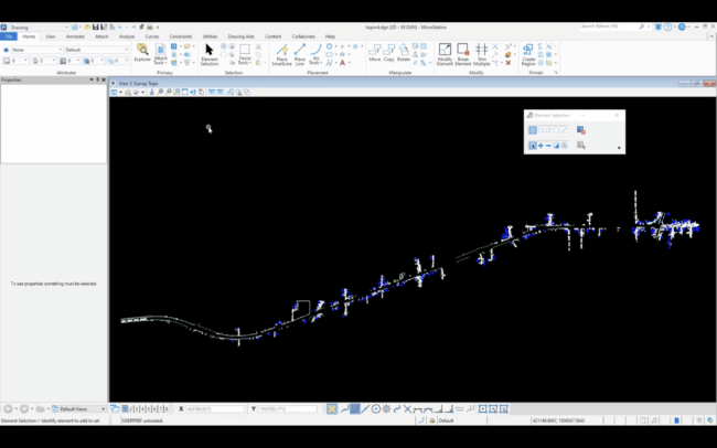
MicroStation User Interface (source)
Tabs and Ribbons
As with all other applications developed in the graphical user interface (GUI) era, MicroStation uses graphical icons tiered into tabs and housed in menus that you can toggle on or off. At first glance, the user interface is quite simple. It features tabs that include: File, Home, View, Annotate, Attach, Analyze, Curves, Constraints, Utilities, Drawing Aids, Content, Collaborate, and help.
Under each of these tabs are tools grouped into ribbons. For instance, the home tab features the Attributes, Primary, Selection, Placements, Manipulate, Modify, and Groups ribbon groups. As an example, the Manipulate ribbon group contains tools such as Move, Copy, Rotate, and more.
Toolbars, Windows, and Panels
The interface also includes a customizable quick access toolbar that houses commonly used functions such as Save, Save View Settings, Redo, Undo, and more. It also has a search bar and a workflow menu. The workflow menu allows you to choose among different workflows, including Drawing, Task Navigation, and Learning Connect. Your selection determines the tabs that will be displayed on the user interface.
Below the tab section is the working area known as the view. The view includes the name of the drawing (not the file) as well as icons along the top view border. An independent window, movable to the left or right of the work area, displays different panels depending on your preferences. Notably, the window can be turned off altogether.
By default, this window houses the Properties panel, which shows you the properties of a given part of a drawing when you select that specific part/selection. However, you can customize it to include additional panels such as Explorer, View Attributes, Change View Display Style, just to mention a few.
MicroStation also has another toolbar as well as a status bar on the bottom section. The toolbar is segmented into several sections that change depending on the selected display mode. Even so, some of the sections remain unchanged, such as the display mode selector. The selector allows you to change the display mode (we’ll talk more about what the display mode does a bit later on).
In addition, the status bar shows the active function (on the extreme right end as well as on the subsequent section), with instructions on the next action you should perform. This bar also enables you to lock and unlock the display mode.
Themes
With Bentley MicroStation, you can choose between a dark-themed interface and a light-themed interface. To change these settings according to your preference, click the File tab. Next, select Settings > User settings > Preferences. This will display a popup window. Under the Look and feel section, check or uncheck the Apply Dark Themed UI box. Finally, click OK.
Popup Menu
On Bentley MicroStation, tapping the Space bar displays the popup menu. The menu has three rows, the first and third of which contain icons that individually open a secondary dialog that allows you to choose additional tools. The second row contains discrete tools such as Move, Element Selection, Copy, and more.
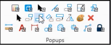
Popup Window on MicroStation (source)
Drawing Tools
A majority of the drawing tools on Bentley MicroStation are found within the Placement ribbon group on the Home tab. Instead of using the term ‘draw,’ the software uses ‘place.’ Thus, simply click the Place Line function to draw a line. Other tools include Place SmartLine, Arc Tools, Place Circle, Place Block, Ellipse Tools, and many more.
You can use the instructions displayed on the status bar to guide you on how to proceed upon clicking one of the drawing tools. At the same time, each tool has a unique Tool Settings window that allows you to change the settings depending on what you are drawing. For instance, you can alter the drawing method, fill type, fill color, and border.
Customization
Bentley MicroStation allows you to customize various settings. Simply click File > Settings > Preferences. This will result in a popup window that lets you make the necessary changes.
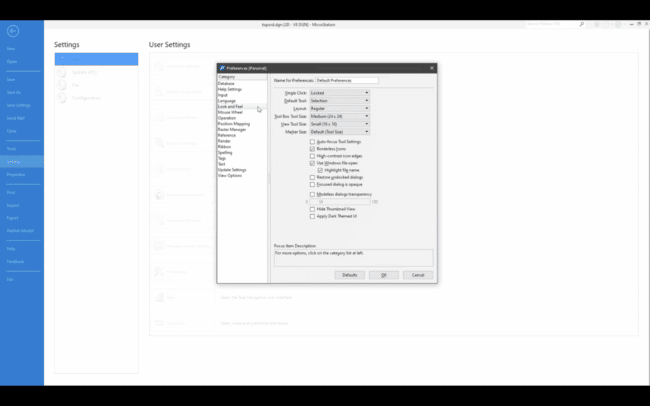
Preferences Window on MicroStation (source)
Units
If you or your organization use a particular unit for all your drawings, you can set the default units and save them as part of the Design File Settings. To do this, click File > Settings > File > Design File Settings > Working Units (on the resultant pop-up window). It is noteworthy that with Bentley MicroStation, you can choose either the master and subunits or just one of them. For example, if you use the imperial system, you can set the master unit as feet and the subunit as inches.
Having covered some basic elements of the software, it’s now time to learn Bentley MicroStation in terms of its capabilities.
Learn Bentley MicroStation Basics: Capabilities
Marketed as “The CAD leader for infrastructure design,” Bentley MicroStation supports 2D drafting, solid (3D) modeling, rendering, editing, visualization, annotation, documentation, assembly sequencing, collaboration, and file importation and exportation, to mention a few. Moreover, the software can produce 2D drawings from 3D models and generate property-driven reports.
To help you learn Bentley Microstation, we will explore these capabilities, starting with visualization.
Visualization
Visualization, also known as simulation, refers to the production of photo-realistic 3D images and models, thereby visually representing a 2D design or concept in an easy-to-understand manner. It enables clients and project owners to view and understand what their project entails in a much more tangible way. While other CAD programs also support visualization, MicroStation has an in-built engine that takes the capabilities a notch higher.
MicroStation is powered by iTwin, a trademarked brand under Bentley Systems’ product offerings that enables users to create visual representations of live construction information in 2D, 3D, and 4D offline and in real-time. The platform puts together disparate data into a combined ecosystem that represents the current conditions for inspections and reporting. Additionally, it predicts future states and settings.
iTwin stores the visualized information in robust cloud infrastructure, meaning users can access them anywhere, anytime. It is noteworthy that the iTwin visualization engine not only facilitates immersive visualization but also generates AI and ML-driven insights. Together, these distinct capabilities support and improve decision-making during the design, construction, and operation stages of a project’s life cycle.
Design Analysis
In tandem with design visualization, Bentley MicroStation also enables you to perform precise analysis. For instance, you can use the software to analyze the solar exposure for projects set to be constructed in a built urban environment. At the same time, you can quickly analyze the impact of shadows cast by surrounding buildings at any time of the day or year.
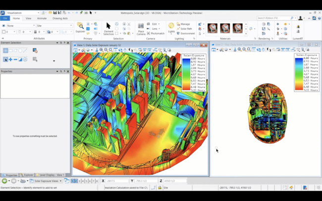
Solar Exposure Analysis on MicroStation (source)
Standards Checking Capabilities
Bentley MicroStation is also packed with standards-checking tools that automatically conduct checks when prompted. The reviews compare a drawing’s/model’s properties against properties defined by existing standards. These comparisons enable the software to identify anomalies and, in some cases, fix the problems.
Data-Handling Capabilities
In addition, MicroStation can handle both miniature-sized and large-scale data demands synonymous with infrastructure projects. As such, this CAD software can seamlessly generate efficient 2D drawings and 3D models regardless of the size of the survey data. Bentley MicroStation can import, process, and plot survey data.
Importantly, though, Bentley MicroStation does not just work with the survey or geospatial data. This is because it allows you to incorporate imagery into your design as well as photo-textured reality meshes produced from ordinary photographs. As such, you do not need to create everything from scratch. This capability helps you provide the exact and accurate context for your projects as well as communicate your design intent effectively.
The software even goes a step further by supporting different display modes. Some of the modes include illustration, monochrome, transparent, and smooth. By toggling the transparent mode, for example, you can view subsurface features, such as pipes, canals, and ducts that would otherwise be hidden in other display modes.
Interoperability
A design project might comprise different organizations and professionals with differing preferences with regards to their ideal CAD software. If yours is Bentley MicroStation, yet other players prefer other CAD programs, you need to worry.
Bentley MicroStation supports interoperability. It seamlessly opens other proprietary file formats such as Autodesk’s .dwg, SketchUp’s .skp, 3Ds Max’s .3ds, Industrial Foundation Classes’ (IFC) eponymous format, common raster formats, shapefiles, openNURBS’ .3dm, and more.
What’s more, Bentley Systems has licensed the real DWG libraries directly from Autodesk. As a result, Bentley MicroStation users can use and produce DWG files. The software even supports versions that go back to 1997.
The software’s interoperability works such that you can import designs stored in other file formats without loss of precise geometrical properties and important BIM and geospatial information. As such, MicroStation supports the lossless sharing of design data/information. Doing so saves time that would have otherwise been spent recreating existing data, which is known to result in errors.
Supported File Formats on MicroStation (source)
Automatic Saving
Unlike programs such as Microsoft Word, Excel, and AutoCAD, which require the user to save the changes for the programs to write the edits into the file, Bentley MicroStation does this automatically. It automatically writes the changes into the file without the user clicking the Save icon or the Ctrl+S shortcut combination.
Extra Resources
We have covered the basics, thus providing you with the necessary material to learn Bentley MicroStation. However, if you are looking to become a Bentley MicroStation expert, you can go a step further.
Bentley Systems offers learning resources on the Bentley MicroStation and Bentley Education YouTube channels. As well, the company provides education/learning programs for users, educators, and students as listed below:
- Bentley Systems program for users
- Bentley Systems’ program for students and educators
At the same time, the software natively enables users to learn Bentley MicroStation thanks to the integrated content, known as the Bentley CONNECT Advisor installed with the MicroStation CONNECT Edition.
If your organization uses other CAD software instead of Bentley MicroStation, you can check out our other guides by clicking here.

CAD software Bentley MicroStation, commonly referred to as MicroStation, provides design, 2D drafting, and 3D modelling. It was created and is offered for sale by Bentley Systems, Inc. Infrastructure specialists from the building, civil engineering, architectural, planning, energy,, transportation, higher education and other sectors can deliver and coordinate on projects thanks to their features, capabilities, and tools. Additionally, it has a wide range of BIM (Building Information Modeling) features.
Having a market share of roughly 0.53% in the engineering and computer-aided design sectors. MicroStation may not have as many users as Autodesk’s SolidWorks or AutoCAD. A software called Enlyft searches for and understands firms all across the world using machine learning and artificial intelligence.
This is the reason we wrote this article to teach you the fundamentals of Bentley MicroStation in just one hour. We will examine its orientation and user interface, as well as the available file types, editing and drawing tools, and more.
Microstation Tutorial — Table of Contents
- Basics of MicroStation: Orientation
- User Interface of MicroStation
- Popup Menu
- Drawing Tools
- Customisation
- Units
- Basics of Bentley MicroStation: Capabilities
- Visualization
- Design Analysis
- Capabilities for Standards Checking
- Capabilities for Data-Handling
- Interoperability
- Automatic Saving
Basics of MicroStation: Orientation
You must have experience with one or more CAD applications if you work in the building or design industry. And as you may have noticed, they have very different user interfaces and functionalities.
Therefore, everyone understands the need of taking a few minutes to get accustomed to an application’s user interface. In fact, it significantly aids in later workflow improvement. This article will start by giving a general overview of the interface. By the way, this is the first step towards learning the fundamentals of Bentley MicroStation.
User Interface of MicroStation
Ribbons and Tabs
The graphical icons used by MicroStation are separated into tabs and kept in menus that you can toggle off or on, just like all other apps created in the graphical user interface (GUI) period. The user interface appears straightforward at first look. File, View, Home, Analyze, Annotate, Attach, Utilities,Curves, Constraints, Content, Drawing Aids, Collaborate, and Help are some of the tabs that are present.
Ribbon-based groups of tools are located under each of these tabs. For instance, Placements, the Primary, Attributes, Selection, Modify, Manipulate, and Groups ribbon groups are available on the home tab. The Manipulate ribbon group, for instance, has capabilities like Copy, Rotate, Move and more.
If you want to enrich your career and become a professional in CATIA, then visit Mindmajix — a global online training platform: «CATIA Online Certification» This course will help you to achieve excellence in this domain.
Windows, Toolbars, and Panels
The user interface also has a quick access toolbar that is customisable and contains often used features like Save, Redo, Save View Settings, more and undo. A workflow menu and a search bar are also included. You can select from a variety of workflows, such as Learning Connect, Task Navigation, and Drawing using the workflow menu. The tabs that appear on the user interface are determined by your choice.
The working space known as the view is located beneath the tab section. The drawing’s title appears in the view along with icons along the top border. Depending on your settings, Several panels are displayed in a separate window that can be dragged to the right or left of the work area. Notably, the window can be completely shut off.
When you pick a particular part or selection within a drawing, the Properties panel in this window, which is present by default, displays the properties of that part or selection. To name a few, you can edit it to incorporate extra panels like View Attributes, Explorer, and Change View Display Style.

On the bottom portion of MicroStation, there is a status bar and an additional toolbar. Several components of the toolbar are divided up, and they vary based on the chosen display mode. Nevertheless, some of the components, such the display mode selector, are unchanged. You can alter the display mode using the selector (we’ll go into more detail about what the display mode does later).
Additionally, the status bar displays the active function together with instructions for the upcoming action (on the very right end as well as in the part below). The display mode can also be locked and unlocked using this bar.
Themes
You can select between a light-themed interface and a dark-themed interface in Bentley MicroStation. Click the File tab to modify these parameters to suit your preferences. Select Preferences after choosing Settings > User settings. Pop-up windows will appear as a result. Uncheck or check the Apply Dark Themed UI box under the Look and feel section. After that, click OK.
Popup Menu
The popup menu is displayed on Bentley MicroStation when the Space bar is tapped. The menu is divided into three rows, and the third and first rows each contain icons that, when clicked, open a new dialogue box where you can choose additional tools. Discrete tools like Element Selection, Move, Copy, and others are found in the second row.
Drawing Tools
The Placement ribbon group on the Home tab of Bentley MicroStation contains the majority of the drawing tools. The software utilises the word «place» in place of the word «draw.» To draw a line, just use the Place Line function. Place SmartLine, Arc, Circle, Block, Ellipse, and many more more tools are available.
When you click one of the drawing tools, you can utilise the directions that are shown on the status bar to help you know what to do next. Each tool has its own Tool Settings window, which you can use to adjust the settings according to what you are sketching. For instance, you can change the border, fill type, fill colour, and drawing technique.
Customisation
With Bentley MicroStation, you may alter a number of settings. Choose Preferences by clicking File > Settings. This will cause a popup window to appear where you may make the necessary adjustments.
Source
Units
Default units can be set and preserved under Design File Settings if you or your business routinely uses that unit for all of your designs.
Notably, you can select either the subunits and master or simply one of them while using Bentley MicroStation. Use feet as the master unit and inches as the subunit, for instance, if you’re using the imperial system.
After going through some of the software’s fundamental components, it’s time to learn about Bentley MicroStation’s capabilities.
Basics of Bentley MicroStation: Capabilities
Bentley MicroStation is promoted as «The CAD leader for infrastructure design» and offers a variety of features, including 2D drafting, solid (3D) modelling, rendering, editing, visualisation, documentation, annotation, collaboration, assembly sequencing, and file import and export.
The software can also create property-driven reports and 2D graphics from 3D models.
We will examine these features, beginning with visualisation, to assist you in learning Bentley Microstation.
Visualization
Visualization, commonly referred to as simulation, is the process of creating photorealistic 3D models and visuals that clearly depict concept or a 2D design. It makes it much easier for project owners and clients to observe and comprehend the details of their project. While other CAD products offer visualisation assistance as well, MicroStation features an integrated engine that raises the bar.
With the use of iTwin, a Bentley Systems trademarked brand that powers MicroStation, users can offline and in real-time build 2D, 3D, and 4D visual representations of actual construction information. In order to depict the current conditions for inspections and reporting, the platform combines diverse data into a single ecosystem. It also forecasts future settings and states.
Users can access the graphical data at any time, anywhere thanks to iTwin’s reliable cloud infrastructure. It is interesting that the iTwin visualisation engine produces insights driven by ML and AI in addition to enabling immersive visualisation. Together, these unique capabilities help and enhance decision-making throughout the project’s construction, design, and operation phases.
Design Analysis
Bentley MicroStation allows you to conduct accurate analysis in addition to design visualisation.
For projects planned for construction in a built urban setting, for example, you can use the software to analyse the solar exposure. At any time of day or year, you can instantly assess the effect of shadows created by neighbouring structures.
Capabilities for Standards Checking
Standard-checking tools are also abundant in Bentley MicroStation and run checks as necessary. The reviews compare a drawing’s or model’s characteristics to those outlined by accepted standards. The software can detect irregularities and, in some situations, correct the issues thanks to these comparisons.
Capabilities for Data-Handling
Additionally, MicroStation can manage the small- and large-scale data requirements associated with infrastructure projects. Because of this, this CAD programme can produce effective 3D models and 2D drawings regardless of the volume of the survey data. Data from surveys can be imported, processed, and plotted using Bentley MicroStation.
However, Bentley MicroStation does more than only use geospatial or survey data, which is significant. This is due to the fact that it enables you to use photo-textured reality models made from common images as well as visuals in your design. As a result, you do not have to start from beginning. With the use of this skill, you may accurately and precisely describe the context of your projects while also effectively communicating the design objective.
Different display modes are supported by the programme, taking it a step further.
Among the modes are smooth, translucent, monochrome, and illustrative. By switching to the translucent mode, for example, you can see subsurface objects like canals, pipelines, and ducts that are normally obscured in other display modes.
Interoperability
Varying businesses and professionals with different preferences for their ideal CAD software may be involved in a design project. If you use Bentley MicroStation and the other participants favour different CAD applications, you should be concerned.
Interoperability is supported by Bentley MicroStation. Other proprietary file types include Autodesk’s.dwg, SketchUp’s.skp, 3Ds Max’s.3ds, the Industrial Foundation Classes (IFC) format, shapefiles, common raster formats, openNURBS’.3dm, and others are all open with ease.
Additionally, Bentley Systems has a direct licence from Autodesk for the authentic DWG libraries. As a result, DWG files can be used and created by Bentley MicroStation users.
Even versions from 1997 are supported by the software today.
The software’s interoperability allows you to import designs stored in various file formats without losing crucial BIM and geographical data or accurate geometrical features. As a result, MicroStation encourages the lossless exchange of design data and information. By doing this, time that would otherwise be spent incorrectly reproducing already-existing data is saved.
Automatic Saving
Bentley MicroStation automatically writes the edits into the file, unlike other programmes like Excel, Microsoft Word, and AutoCAD that demand the user to save the changes.
Without the user selecting the Save icon or pressing the Ctrl+S keyboard shortcut, the changes are automatically written into the file.
Conclusion
MicroStation can be used by designers, engineers, architects, and draftspeople. Leading project teams, from independent consultants to global design organisations, depend on MicroStation to successfully complete projects of any size and complexity.
0+ Материал без явных возрастных ограничений
Научись практически использовать программу для моделирования САПР MicroStation V8i.
Основы проектирования в САПР MicroStation V8i — специальная книга, которая поможет тебе освоить сложное моделирование.
Этот учебник является наиболее востребованным и полным пособием на русском языке CAD системы MicroStation V8i фирмы Bentley Systems Incorporated. Он представляет из себя собрание практических и справочных данных, которые дают возможность максимально понять принципы MicroStation и освоить практические навыки, работая с ее средой. Рациональная организация материала, в котором также присутствуют учебные упражнения, позволяет тебе эффективно использовать все функциональные возможности V8i.
Здесь ты найдешь описание и принципы действия разных инструментальных средств: модификация элементов, использование и манипулирование ассоциированными файлами, новые Internet утилиты, эффективные методы 3D проектирования и визуализации, наполненное изображениями практических примеров, и меню дает возможность обучающемуся лицу перейти к практическому выполнению индивидуальных проектов.
Информация:
Создан:
2016, 03 апреля, в 19:43
Автор:
А.Н. Божко, Д.М. Жук, В.Б. Маничев
Изображения:
Высокая скорость
Скачивайте очень быстро…
Прямые ссылки
Все файлы хранятся у нас. Качайте быстрее…
Безопасно
Вирусов и других угроз НЕТ! Проверено ESET
Файл:
Добро пожаловать!
Войдите или зарегистрируйтесь сейчас!
Войти
Что можно поменять в видео
-
Коллеги, здравствуйте!
Для тех, кто решил начать работу в этом замечательном программном комплексе, предлагаю серию коротких ознакомительных видео. Приятного просмотра!Видео с обзором интерфейса
Видео с обзором инструментов черчения
Видео с обзором редактирования примитивов
Видео с обзором инструментов для манипуляции примитивами
Жду ваших замечаний, предложений, ответов на голосование и благодарю вас за просмотр!
#1
-
Форумчанин
- Регистрация:
- 29 июн 2014
- Сообщения:
- 237
- Симпатии:
- 52
Здравствуйте, подскажите, кто ей пользовался, топосъемку в ней можно отрисовать или как в автокаде — только с «примочками»?
#2
-
Форумчанин
В MicroStation многие вещи делают быстрее и проще, плюс самосохранение, хорошо работает с большими растрами, плюс работа с растрами. 8я версия хорошо дружит с автокадом, как открывает DWG файлы, так и сохраняет в этом формате.
#3
-
Форумчанин
- Регистрация:
- 26 мар 2009
- Сообщения:
- 2.452
- Симпатии:
- 1.038
- Адрес:
-
Киев
Только с примочками, но примочек против автокада несоизмеримо меньше.
В проектном институте ВНИПИТРАНСГАЗ (г. Киев) когда то давно был разработан комплекс программ для рисовки топопланов в MicroStation J.
Наша контора УКРГАЗПРОЕКТ купила сии программы.
Создавать программы пользователю для MicroStation значительно сложнее, нежели для AutoCad, бо на русском языке литературы по программированию для MicroStation нет.
Я в свое время написал для MicroStation V8 программу по отрисовки откоса.
Эта программа выложена здесь на форуме в теме посвященной микростейшен.
http://geodesist.ru/threads/microstation.4691/page-5
#4
Последнее редактирование: 4 сен 2019
-
Форумчанин
Русифицируйте и люди к вам потянутся.
#5
-
Форумчанин
Так есть русские версии, отпугивает негуманный ценник и то, что в ней мало кто работает. В бытность работы на разрезе маркшейдера 7й интенсивно пользовались, были написанные макросы под нее.
#6
-
Форумчанин
Официальные локализации?
Я просто давно не касался этого ПО.#7
-
Форумчанин
Конечно официальные релизы, в плане удобства отличается от продукции AutoDesk, в их Civil не нашли российских стандартов. Мы постоянно пользуемся Deskartes, для архитектуры планшеты, то есть 2х цветные растры, штампуем. К сожалению дополнения, типы линий, шрифты, блоки, они уже условные знаки, лежат на рабочем компе.
#8
-
Форумчанин
Вы их не установили при инсталляции.
#9
-
Форумчанин
Возможно, надо будет попробовать переустановить
#10
-
Здравствуйте!
Я работаю со специалистами, кто полностью оформляет лазерную съемку в этой среде. Дополнительно используется несколько программ написанных на VBA, для заливки угодий. Но специалистов, кто одинаково хорошо разбирается и в автокаде и в микрике я еще не встречал. Возможно, мои коллеги меня поправят, но при полном вникании в то, как работает эта программа, автокад покажется немного устаревшим.
Должен признаться, что я до последнего держался за Civil в обработке, но объективные плюсы этой программы привели меня к комбинации микрика и автокада.
Благодарю за проявленный интерес, обращайтесь с вопросами, я обязательно отвечу.#11
-
- Регистрация:
- 15 фев 2015
- Сообщения:
- 1
- Симпатии:
- 0
Товарищи! Нужна помощь, может кто сталкивался. При переводе в растр в программе microstation текст переводится контуром. До этого всё работало отлично. В чём может быть проблема?
#12
-
Форумчанин
Проверьте настройки «Штампа»
#13
-
Форумчанин
- Регистрация:
- 12 дек 2012
- Сообщения:
- 27
- Симпатии:
- 0
Можно ли подключить в данной программе порядка нескольких тысяч чертежей различных частей города (dwg в координатах), чтобы было без тормозов или вызвать отображение только нужных чертежей из какой либо БД при помощи рамки выбора?
#14
-
- Регистрация:
- 4 мар 2022
- Сообщения:
- 1
- Симпатии:
- 0
всех приветствую, подскажите почему при первоначальном запуске microstation v8i отсутствуют стандартные слои. например отметки ЛЭП, рельеф, улицы и тд…?
#15
-
Форумчанин
редактируйте шаблон, все тоже самое как в автокаде
#16
-
- Регистрация:
- 22 янв 2014
- Сообщения:
- 4
- Симпатии:
- 5
Добрый день, коллеги, помогите, давно не пользовалась MicroStation V8, нужны условные знаки для отрисовки различных заборов для межевого плана, по Москве вдруг затребовали((( Как их подгрузить не могу найти никак?????
#17

Поделиться этой страницей
Need a manual for your Bentley MicroStation V8? Below you can view and download the PDF manual for free. There are also frequently asked questions, a product rating and feedback from users to enable you to optimally use your product. If this is not the manual you want, please contact us.
Is your product defective and the manual offers no solution? Go to a Repair Café for free repair services.
Manual

Rating
Let us know what you think about the Bentley MicroStation V8 by leaving a product rating. Want to share your experiences with this product or ask a question? Please leave a comment at the bottom of the page.
Are you satisfied with this Bentley product?
Yes No
3 votes

Microstation Basic Training Manual
Table of Contents Microstation Manager Dialog box …………………………………………………………………………………………………………………………………….3
Open File:…………………………………………………………………………………………………………………………………………………………………..3
New dialog box: ………………………………………………………………………………………………………………………………………………………….4
Seed File: …………………………………………………………………………………………………………………………………………………………………..4
File location: ………………………………………………………………………………………………………………………………………………………………….5
Difference between 2D and 3D ………………………………………………………………………………………………………………………………………..5
Microstation Button/Box Concept …………………………………………………………………………………………………………………………………….5
MicroStation Window Layout …………………………………………………………………………………………………………………………………………..6
Standard Tool Box: ……………………………………………………………………………………………………………………………………………………..6
Primary Tools: …………………………………………………………………………………………………………………………………………………………….7
Attributes:………………………………………………………………………………………………………………………………………………………………….7
Main Toolbar: …………………………………………………………………………………………………………………………………………………………….7
Task Navigation (Drawing Task): ……………………………………………………………………………………………………………………………………8
View Controls: ……………………………………………………………………………………………………………………………………………………………8
Basic Microstation drawing elements ……………………………………………………………………………………………………………………………….9
View: …………………………………………………………………………………………………………………………………………………………………………..11
View Attributes …………………………………………………………………………………………………………………………………………………………12
Saved Views ……………………………………………………………………………………………………………………………………………………………..12
Introduction to Symbology …………………………………………………………………………………………………………………………………………….13
Level Manger ……………………………………………………………………………………………………………………………………………………………13
Level display …………………………………………………………………………………………………………………………………………………………….13
Attributes Toolbar …………………………………………………………………………………………………………………………………………………….13
Level Attributes ………………………………………………………………………………………………………………………………………………………..13
Button Assignment ……………………………………………………………………………………………………………………………………………………….14
Design File Settings ……………………………………………………………………………………………………………………………………………………….14
Working Units …………………………………………………………………………………………………………………………………………………………..14
Preferences ………………………………………………………………………………………………………………………………………………………………….14
Operation ………………………………………………………………………………………………………………………………………………………………..14
Saving File and Settings ……………………………………………………………………………………………………………………………………………..14
Accudraw …………………………………………………………………………………………………………………………………………………………………….15
Accudraw …………………………………………………………………………………………………………………………………………………………………15
Polar Coordinate ……………………………………………………………………………………………………………………………………………………….15
Accudraw Calculator ………………………………………………………………………………………………………………………………………………….15
Accudraw Shortcuts …………………………………………………………………………………………………………………………………………………..15
Snap ……………………………………………………………………………………………………………………………………………………………………………16
Text and Dimensioning ………………………………………………………………………………………………………………………………………………….16
Maniplating and Modifying Elements ………………………………………………………………………………………………………………………………17
References …………………………………………………………………………………………………………………………………………………………………..17

Naming Convention ………………………………………………………………………………………………………………………………………………………18
Shortcut Keys: ………………………………………………………………………………………………………………………………………………………………18
Layout ……………………………………………………………………………………………………………………………………………………………………..18
Key-In: ……………………………………………………………………………………………………………………………………………………………………..18
Comfort: ………………………………………………………………………………………………………………………………………………………………….18
Designing Efficiency: ……………………………………………………………………………………………………………………………………………………..18
Ask Yourself ……………………………………………………………………………………………………………………………………………………………..18
Efficiency is not speed ……………………………………………………………………………………………………………………………………………….18
3D Design Concepts: ……………………………………………………………………………………………………………………………………………………..18

Microstation Manager Dialog box
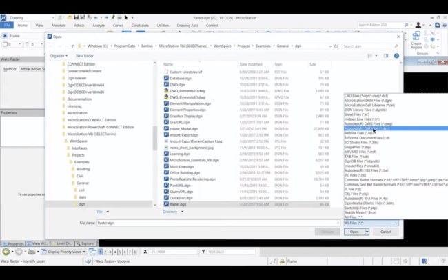
Open File:
When you start MicroStation without designating a DGN/DWG file to be opened automatically, the first dialog box you see is MicroStation Manger. The Look in, List Box, File Name, Files of Type, Open, Icon Bar, and Options controls are corresponding to those in the Open dialog box, which opens when ‘File Open’ is chosen in MicroStation. The most commonly used buttons have been highlighted below.
Annotation 1. ‘New File’. Opens the ‘New Dialog Box’, which is used to open a design file as the active file 2. ‘User’. This sets the MicroStation environment or configuration that you want the next DGN File session to use. These are set up by your CAD Administrators. 3. ‘Project’. Sets the location and names of data files associated with a specific project configuration.
1
2 3

New dialog box:
Used to create and open a DGN/DWG file as the active DGN/DWG file. Opens when ‘File New’ is chosen.
Seed File:
Seed files When you create a DGN file, you identify a seed file as a template for the DGN file. The new DGN file is actually a copy of the seed file.
Seed files do not (necessarily) contain elements but, like other DGN files, they contain at least one (default) model, settings, and view configurations. You should create a seed file with customized settings so that you don’t have to adjust settings each time you open/create a DGN file. To optimize work flow you can have a different seed file for each type of drawing. General seed files will be made by CAD Administrator appointed to the corresponding project.
A number of discipline-specific seed files are provided with Microstation, in addition to the generic seed files, ‘seed2d.dgn’ and ‘seed3d.dgn.’ In Ramboll’s main office, seed file area kept in K drive \\rogqasql32\ustn under MSXM and then client, and are setup by a CAD administrator.
To select a seed file
1. From the File menu, choose New.
The New dialog box opens.
2. Click the Browse button adjacent to the Seed field.
The Select Seed File dialog box opens. The default filter is ‘MicroStation DGN Files [*.dgn].’
3. In the list box, select the desired seed file.
Or
In the File name field, key in the name of the desired seed file.
4. Click Open.

File location: Currently at Ramboll we are using the K: drive to store our Seed files, Cell files, plot drivers and other files. Make sure you have K drive mapped out before you start any project as it will enable usage of User & Project in the Microstation Manager
Difference between 2D and 3D 2D and 3D refer to the actual dimensions in a computer’s workspace. 2D is ‘flat’, using the X & Y (horizontal and vertical) axis’, the image has only two dimensions and if turned to the side becomes a line. 3D adds the ‘Z’ dimension. This third dimension allows for rotation and depth. When drafting or designing be careful as some 2D drawings are 3D DGN and can cause complications later. It is recommended to check that side/front have elements lying flat line. To avoid this it is advised to lock the z axis if drafting under the above situation.
Microstation Button/Box Concept MicroStation has a concept of using buttons and drag boxes. A common method is to setup the frequently used tool boxes and docking them into the centre or the sides of MicroStation. Once a user chooses a tool they will know it is active by the status bar and from the active tool settings (the box header will turn dark blue), pressing [F10] will move focus to the open tool settings box.
In the Main Tool box with the exception of ‘Element Selection'(1) and ‘Delete Element'(8), the tools in the Main tool box are also members of a ‘child’ tool box. When you point to one of the other tools holding down the data button, a drop-down menu opens from which a tool in the child tool box can be selected. The child tool box can be ‘torn off’ and floated by choosing Open as Toolbox from the drop-down menu. When a tool is selected in a child tool box (attached or floating), the tool automatically becomes the ‘representative’ of the child tool box in the Main tool box. And a tools setting box will appear on screen.
Tool Settings (Active) Tool Settings
(Inactive) Child Toolbox
Main Toolbox

MicroStation Window Layout
Standard Tool Box:
Main Toolbar
Task Navigation
Attribute Primary Tools Standard
Accudraw Key-In View Groups
View Controls
Print (‘ FilePrint ‘)
New (‘ FileNew ‘)
Open (‘ FileOpen ‘)
Save (‘ FileSave ‘)
Cut (‘ EditCut ‘)
Copy (‘ EditCopy ‘)
Help (‘ HelpContents ‘)
Bentley Library
Redo (‘EditRedo ‘)
Undo (‘ EditUndo ‘)
Paste (‘ EditPaste ‘)
Status Bar

Primary Tools:
Attributes:
Main Toolbar:
Element Selection
Fence tool box (Place Fence)
Manipulate tool box (Copy)
View Control tool box (Update View)
Change Attributes tool box (Change Element Attributes)
Groups tool box (Drop Element)
Modify tool box (Modify Element)
Delete Element
This tool bar is used to select general usage element selection, manipulation, and modification tools. The table above shows the ‘as delivered’ arrangement of the Main tool box and identifies the corresponding child tool boxes.
Active Line Style
Active Element Template
Active Level
Active Colour
Active Line Weight
Active Element Transparency
Active Element Priority
Level Display
Models
References
Level Manager
Element Information
Toggle Accudraw
PopSet Disable

Task Navigation (Drawing Task):
Linear task (Place SmartLine)
Polygons task (Place Block)
Ellipses task (Place Circle)
Patterns task (Hatch Area)
Tags task (Attach Tags)
Text task (Place Text)
Cells task (Place Active Cell)
Measure task (Measure Distance)
Dimensioning task (Dimension Element)
The Task Navigation tool box contains the Task List and the tools of the active task. In the as-delivered application window layout, the Task Navigation tool box is docked to the right-hand edge of the application window, and the active task is the Drawing task. To change task, you have to click on ‘sphere on a triangle’ button and select the approperite task. To see what is in a task simply press the ‘+’ buttons to see. The table above shows the ‘as delivered’ arrangement of the Main tool box and identifies the corresponding child tool boxes.
View Controls:
View Controls are used to manipulate a view, the most commonly used View Controls can be selected in the View Control Bar docked to the top of each view window. Above is the standard setup of the’ View Control Bar’, to add or remove buttons simply right click and toggle between off and on.
Zoom Out
New (‘ FileNew ‘)
Update View
Zoom In
Window Area
Fit View
View Display Mode
Change View Perspective
Copy View
View Next
View Previous
Rotate View
Navigate View
Pan View

Basic Microstation drawing elements Under Area there is, fill type, and fill colour. You can change the fill type to opaque or outlined. Opaque will place the circle and fill the object with fill colour you choose. Outlined will also place the circle with fill colour, but still preserve the outline colour. Toggling on ‘Diameter’ will allow you to place a circle with the placement point set by method model. Each Method allows for different ways to place a circle, the different methods are explained bellow.
Placing an arc is quite similar to placing a circle. The most commonly used ‘Method’ is ‘Start, End, Mid’, all methods for an arc have self explanatory names and are easy to use with a little practice. Note when using and unsure of the next step look to the bottom left to the Status Bar to see what the next step is.
Although called SmartLine you can use it to make multiple element types, such as
Line, if it only has one line segment
Arc, if it only has one arc segment
Line string, if it has several line segments
Complex chain, if it has several line and arc segments
Complex shape, if it’s a closed element
A SmartLine can have arc and lines. You can change the segment type from line to arc and vice versa during placement of the element. You can also change the vertex type to rounded (fillet) or chamfered.
Using [~] you can toggle between the top most parameter in the active tool setting.
Place Line allows you to place a line according to parameters set in the tool settings. If you draw 4 line segments it will split into 4 line segments (Unlike SmartLine’s ‘Join Elements’).
1
2
Centre
User defines two points: the centre point and a point on the edge
Edge Diameter
User defines three points on the circle edge
User defines two points on the circles edge as the diameter
1 2
2
3
1

Place Block places a rectangle, as MicroStation calls rectangles, blocks. They are simple to place and have two methods of placement. See below.
Place shape is like place SmartLine but you have to define the last data point as the first data point as well. Close Element button automatically closes the shape for the user. Orthogonal shape is similar to place shape. The only difference is the edges are perpendicular to each other.
Orthogonal
2
1
Orthogonal requires the user to define two points at the block opposite corners.
Rotated
2
3
1
Rotated requires the user to define three points, start point, rotation point and the opposite corner of the start point.

View: Whether a large & complex drawing or a simple 2D drawing, the additional windows in MicroStation give you an invaluable advantage. With a 3d drawing the views can be setup to different angles/perspectives for 3d, or simple to avoid zooming in & out by show different areas. The most views that can be opened at one time in MicroStation is 8, multiple monitors enhance this feature. Each viewing window can be treated as an individual view, and each can have different view attribute applied to them. This allows for annotation (Text and Tag) or depth to be viewed in one window, not all windows.
View 1. Is the ‘fit view’ of a project from a ‘Top View’.
View 2. Is the ‘Isometric View’ with line weight switched on.
View 3. Is the ‘fit view’ of the project from a ‘Front View’
View 4. Has depth set from the top view and is a ‘Right View’
You can open and close views using the view buttons in the view group.

Or using ‘Window MenuViews’. By using the Window Menu you can also arrange and manage views by using ‘Cascade’, ‘Tile’, or ‘Arrange’. An alternative to panning is to set scroll bars in the view windows, here in the Window Menu this can be done by toggling ‘Scroll Bar’. View Toolbox will place View Toolbox’s on all viewing windows. Selecting ‘Task Navigation in View’ will remove the ‘View Toolbox’ and place a Task navigation tool box in each viewing window. You can only view one toolbar at a time and in order to view either, ‘View Toolbox’ must be toggled on.
Window Area is a very useful tool in MicroStation, especial for 2D. It allows you to define an area in view 3 using the tool but show the selected area in view 2.
View Attributes Each Microstation view has a view attributes window, but by simply changing the ‘View Number’ it changes the window that the View attributes effects. For example, we can show annotations (Text and Tags) in view 1, but turn them off in view 2 or shading in view 1, but wireframe in view 3. Remember that to change an attribute for all views, toggle ‘Apply to All’ on and then make the change.
Saved Views
Saved views will save your configuration for an individual view. Saved views are very important when it come to exporting 3D models to 2D detail drawings. It is important to check your project procedure for guidelines to the naming and describing of a saved view. If clips are using in the view, remember to toggle on ‘Associative Clip Volume’ before saving the view. ‘Associative Clip Volume’ does not save as part of Saved Setting.
When you click Apply the view will be loaded into the view number corresponding to ‘View:’

Introduction to Symbology
Level Manger Each element in a model is on a drawing level. Microstations levels are used to separate and distinguish objects in a drawing, MicroStation level are akin to AutoCAD Layers. You can create, delete and manage levels in general from the ‘Level Manager’. You can open the level manager from ‘Settings Levels Manager’ or double clicking the level name at the bottom right or from Primary Tools Toolbox.
Level can only be deleted if empty. Should a level be empty and won’t delete, check if a shared cell file is using that level. If so detach the cell file and then try to delete the unwanted level. Change the attributes of a level is as simple as clicking the attribute of the level you want to change, then a list box or colour panel will appear and you can change the attributes by clicking the appropriate value. Double clicking or right clicking and selecting ‘set active will set that level as the files active level.
Level display Level Display allows you to have full control of all levels in each view, even in references. It can be opened by ‘Settings Levels Display’ or from the Primary Tools Toolbox. It allows you to view which levels are in use as they have bullets in the ‘Used’ column. If a level is in highlighted dark green then it is the active level in the file, if dark blue then that level is visible in all views. If brown the level is only visible in some views, whereas if white it is turned off in all views.
Attributes Toolbar Microstation level Attributes or Attributes toolbar is docked underneath the main taskbar at the top. MicroStation has many level attributes. By default, it will only show you three attributes: Colour, Line Style, and Line Weight. When clicking on the levels name a drop down list comes up showing the ‘Name’, ‘Display’, ‘Lock’ and ‘Colour’. You can change active level by changing the ‘Name’, to correspond with needed level. Note, holding down [Alt] and clicking on an element will make the attributes bar copy that elements attributes. Also [Shift] + [F2] can be used on the active screen to change levels by selecting the need level from a drop down list. By default, object attributes will use ‘by level’. It means your object will use the attributes you set for that level. However, you may need to override the attributes when you place your objects. You can do this the from attributes toolbar. Remember useless required otherwise keep all attributes to ‘by level’ as default.
Level Attributes MicroStation has two types of line style: standard or custom. The standard Line Styles are mark by number: 0 to 7. While the custom line style are using names (And AutoCAD Styles). To distinguish objects in black and white documents MicroStation uses the line weight. There are 32 line weights, from 0-31. The number is just index, not actual weight (5 is not 0.5 mm). Pen weights will be mapped to an actual plot weights. To Change a levels attributes/level simply select the elements that you want to change and then select the level to switch to from the drop down bars in the attributes toolbar.

Button Assignment
1) [Left click]; is called data point (DP). When an object is to be placed, the user needs to define a data point. A User can define a Data point by clicking the left mouse. Users can also use data point to activate tools from task navigation and as OK/accept button.
2) [Right click]; is called Reset. Reset is used to cancel a running process or finish using a tool. 3) [Middle Button] is called the Tentative Button. This is used for temporary snap. Scrolling with the [Middle Button] will
allow the user to scroll in and out. First time you open MicroStation you’re [Middle Button] will actually be pan, the [Middle Button] should be changed to Tentative as it is easier to use than the left and right click buttons pressed at the same time. Change the button assignment by selecting ‘Workspace Button Assignment’ and select’, Remap Buttons. Select tentative, click with the [Middle Button] in the Button Definition Area. Once this is done you lose the use of pan as the [Middle Button], so alternatives for this are using [Shift] + [Left Click] which allow for trace pan to be used. Or applying scroll bars to view windows is another option. Alternatively you could remap your button so that pan is [Alt] + [Left Click]/ [Right Click].
Design File Settings
Working Units MicroStation works diffrently to AutoCAD in this regard as in the later working units can be changed at any time. Whereas in MicroStation working units if changed, will change the values of the elements already in the file.
You can check your working unit by accessing menu ‘SettingsDesign File’ and click on the category ‘working units’ on the left.
Preferences
Operation When switching to two screens select ‘Workspace Preferences’ and click on the category ‘Operation’. Here you will have to toggle on ‘Open Two Application Windows’, and then close and open MicroStation.
Saving File and Settings Microstation ‘Save File’, saves elements to the file though ‘Filesave’ ([Ctrl] +[S]). Elements mean objects such as lines and complex shapes. Microstation also has save settings, ‘FileSave Settings’ ([Ctrl]+[F]) which saves working units and window views so than when you open the DGN again you will be back in the same area you where in before closing. It is also advised to have ‘Save Settings on Exit’ and ‘Automatically Save Design Changes’ toggled on.

Accudraw
Accudraw Accudraw can help a user place elements precisely and efficiently, and is one of the main advantages of using MicroStation. MicroStation default is to keep the Accudraw tool above ‘Status Bar’, this can be ‘torn off’ and left floating. Leaving this bar floating has the advantages of knowing if Accudraw is active or inactive. You can toggle Accudraw on and off from the Primary Tools bar or press [F11]. Once you enter a data point, the data point becomes the origin for Accudraw and as you move the mouse the X and Y value changes accordingly. Moving it to the right or left of your compass the focus field becomes the X field. The focus field is the field is the highlighted field. If the pointer is moved up and down near the compass, the highlighted field becomes Y. Accudraw focus will always move to a field with the highest value. If the pointer is near to or in line with the X or Y axis, the line becomes thicker and sticks to the axis. It is called ‘indexed’. Indexing will help you to draw lines parallel to the X or Y axis. You can also index their Accudraw by Smartlock, which locks the X, Y or Z axis by pressing [enter]. When Accudraw is active and Smartlock is used all but the highlighted field / selected field will change to yellow. If yellow it means that that axis is locked, once locked you can use [tab] to move to the next field or click another field they want to change. To unlock Accudraw you can press [enter] again or simply toggle the ‘X’,’Y’, or ‘Z’ buttons off. Pressing [Z] when Accudraw is active will lock the Z axis; this can be useful when you want to draw as if in a 2D environment Accudraw compass will be rotated and follow the previous data points orientation. To get the points to reset the compass orientation to the view, press [V] to reset the compass to view orientation. Accudraw comes with practice and most manipulation tools works with Accudraw.
Polar Coordinate During the design process, you may need to use other methods to input your object. Not by X and Y values, but using distance and angle. This is known as polar coordinate. When Accudraw is active press [space bar] to change it to polar coordinate, this will change X and Y to distance and angle. It also changes the
Accudraw Calculator Accudraw has a built-in calculator function. This feature allows for mathematical calculations to be used when placing a data point.
For + or – operator, you should lock the X or Y value first. Otherwise, Accudraw will think you want to input negative or positive values. To lock the x axis press [x] do the same for the y and z axis using the [y] and [z] respectively.
Accudraw Shortcuts When Accudraw is active and you press [Shift] + [/] or [?] it will show you the short cut list for Accudraw.

Snap Snapping is referencing to existing points with our file, as we need to place point at the end of a line, midpoint, and centre of a circle and so on. Using Tentative Snap point is almost like the Accusnap point, but it’s not yellow. It’s a dashed cross. Move your pointer until you see the tentative point. Click the tentative icon. MicroStation will show you which point you are attempting to snap to. The tentative point becomes a large white cross, and MicroStation highlights the object. When it snaps to where you want it, click data point to accept it. This is important if there are a lot of objects in a drawing. Allowing you to review whether they are snapping to the correct object or not. If incorrect, click reset [right click] to cancel it, and try again. At the bottom right next to the Lock icon is a snap icon, if you click it you get the options for snapping. The default snap type is Keypoint. To change snap type simply toggle to the snap type that is required. You can also get this list by [Shift] + [Middle Button] (Make sure [Middle Button] is Tentative). Also if Accudraw is active the user can use quick keys to select a snap type, and to change the Keypoints use [K] to bring up the tool settings. Keypoint is set to default at 2, which means that it divides an element into two. This results into a start, middle and end snap point for a line.
Text and Dimensioning There are many dimensioning and text tools that can be used, following the guides in status bar makes using any one of them easy and simple. And like many MicroStation tools the name explains the tool.
Dimension appearance is controlled by dimension attributes. While each dimension can have different attributes, we can manage them efficiently using dimension styles. You can save different attributes settings in each style. You can access dimension style dialog from element>dimension styles. Style is always the top most parameter in a dimensioning oriented tool setting box, with the exceptions of ‘match dimension attributes’ and’ reassociate dimensions’. This is how you define your dimension alignment. View; will give you dimensions aligned with your view. This is useful if you rotated your views and want to have dimension parallel to your view. Drawing; will give you dimension parallel to your coordinate (ACS). View rotation will not affect the dimension orientation. True; will create dimension parallel to your element. Arbitrary; will place your
dimension arbitrarily. This is very useful if you want to create an isometric dimension. Under location option, you can see what kind of dimension you can create. In this example, you can see dimension types for dimension element. If you activate ‘Association’, this will associate your dimension with the element. If you move the element, resize, or do other modification then the dimension will automatically update. Text appearance is controlled by text attributes. While each text can have different attributes, we can manage them efficiently using text styles. You can save different attributes settings in each style. You can access text style dialog from element>text styles. Style is the top most parameter in Place Text tool settings.

Maniplating and Modifying Elements Element manipulation is easy to use, and will become easier with practice. Most the manipulation tools work similar to AutoCAD with the only difference being ‘Method’ which is incorporated into ‘Scale’, and ‘Rotate’. The methods are
(1) Active Angle — the element(s) are rotated by the Active Angle, which can be keyed in.
(2) 2 Points — the angle of rotation is defined by entering two data points. (3) 3 points — the angle of rotation is defined by three data points.
Modify elements again are similar to those found in AutoCAD and using them is simple as long as you follow the status bar and the tool settings.
References Unlike AutoCAD and Xref you cannot effect any changes on a reference without using specific reference tools. The tools can be found in the ‘toolreferences’ opening the tool box or in the references manager which can be opened from the primary tool box or ‘filereferences’. In the reference manager the select/active references are highlighted by blue. Some normal manipulation tools work when a reference is highlighted such as ‘move’.
(1) These are the reference tools that are also include in the reference tool box. (2) This is the reference list; these columns hold information to some reference properties. From left
to right display, snap-able, selectable and treated like other elements. (3) Here the information for a reference is displayed and can be changed from here.
When referencing into a drawing, maintain a naming convention and check to see if the project has a set naming convention. By default try to keep model name, view or object name in the ‘Logical Name’.
1
2
3

Naming Convention The general rule is to use the naming convention that is layed out by your project leader or CAD manual. Remember that file name, saved view, refrences all must have a correspoinding naming convention for the flow of work and to trace it back to drawings.models. if you merge refrences in a drawing to release a copy remember to Save As and apply the set out name extention, such as _Rev0 or _r1.
Shortcut Keys:
Layout The Microstation keys layout is simple, quick and efficient. The main manipulation toolboxes are under 1-9. Task tools are under Q-R; A-F after opening any toolbox it will appear like a dropdown box, allowing you to select the required option. Tools in the dropdown can also be opened by using the corresponding key between 1-9 and Q-R. Each tool has a Tool Box, these have options that can be changed/edited/selected by clicking on them. To access the active tool settings you would have to use the 3rd set of quick keys which are Y-P, H-L.
Key-In:
To get key-in go to ‘UtilitiesKey-In’, or press [enter] without selecting anything selected or press [F9]. Key-In are general used when accessing tools that aren’t in task navigation. If you type’s p the key-in will display all tools stating with p and once the correct tool is highlighted pressing space will automatically complete the word.
Comfort: Although one can use quick keys to select a tool from a toolbox, it is almost equally as quick to just click on the tool needed as the toolbox appears underneath your cursor or from a docked tool box. If you use shortcut keys ensure you are comfortable with the keys you are using as there is less rework from errors.
Designing Efficiency:
Ask Yourself Sometimes the easiest thing to do is just look at how you are designing and question yourself, is this the easiest way. Any objects that are symmetrical and you are not using mirror ask yourself do you have to draw the whole object or just half. This is one of the most efficient ways to cut down your designing time and it is best to reduces unnecessary keystrokes or mouse movements that are not needed.
Efficiency is not speed Avoid confusing efficiency with speed. Efficiency cuts down on keystrokes and mouse movement, whereas speed is how quickly you do your designing/drafting. It is better to keep your normal speed at all times as it leads to fewer mistakes. Selecting tangents and typing in dimensions should, always been done at normal speed as they can cause the largest rifts in a drawing. Typing in quick keys (Shortcuts) is limited to ones familiarity with a keyboard, and it can be equally as quick to select from toolbars.
3D Design Concepts:
The most basic concept is to work in 4 views at one time. This is to have a top, front, right and isometric view open when designing in 3D. Real World coordinates, even thought sometime we have the RWC it is easier to model by placing one object at 0-0-0 and modelling using that object as your basis. Then move or reference your model to its RWC. Try to avoid objects such as Boolean or B-Spline, as in large models they will slow down the speed at which one can move through or model in.