- Manuals
- Brands
- Beastx Manuals
- Science Education products
- MICROBEAST PLUS
- Manual
-
Contents
-
Table of Contents
-
Bookmarks
Quick Links
BEASTX Wiki:Books/MBPlus 52 ENG
wiki.beastx.com
Related Manuals for Beastx MICROBEAST PLUS
Summary of Contents for Beastx MICROBEAST PLUS
-
Page 1
BEASTX Wiki:Books/MBPlus 52 ENG wiki.beastx.com… -
Page 2
March 22, 2021 On the 28th of April 2012 the contents of the English as well as German Wikibooks and Wikipedia projects were licensed under Creative Commons Attribution-ShareAlike 3.0 Unported license. A URI to this license is given in the list of figures on page 335. If this document is a derived work from the contents of one of these projects and the content was still licensed by the project under this license at the time of derivation this document has to be licensed under the same, a similar or a compatible license, as stated in section 4b of the license. -
Page 3: Table Of Contents
7 Safety Notes 8 Box content and accessories 9 This is what you get when buying the MICROBEAST PLUS 10 This is what you get when buying the MICROBEAST PLUS HD 11 Optional accessory 12 Hardware installation 13 Attaching your Microbeast PLUS to the helicopter…
-
Page 4
Contents 23 Receiver Menu 24 Preset function assignments for Single-line receivers 25 Adjustment on the device 25.1 Point A — Receiver type ……25.2 Function assignment . -
Page 5
Contents 45 Adjustment on the device 45.1 SETUP MENU E — Rudder limits ……103 45.2 SETUP MENU F — Rudder control direction ….103 46 Setup with StudioXm 47 Extra info: Why setting stick endpoints? 48 Extra info: How the gyro works! -
Page 6
Contents 68 SETUP MENU L — Collective pitch 69 Adjustment on the device 70 Setup with StudioXm 71 What pitch is useful for my helicopter? 72 Measuring pitch without pitch gauge 73 SETUP MENU M — Servo limit 74 Adjustment on the device 75 Setup with StudioXm 76 Headspeed Governor 77 What’s a Headspeed Governor? -
Page 7
Contents 91 GOVERNOR MENU E — Throttle signal divider 92 Adjustment on the device 93 Setup with StudioX 94 GOVERNOR MENU F, G & H — Main gear ratio 95 Adjustment on the device 96 Setup with StudioX 97 PARAMETER MENU A — Quick Trim 98 Adjustment at the device 98.1 Trimming the swashplate . -
Page 8
126.1Installation ……..301 126.2Connecting the USB2SYS with your BEASTX device … . 303… -
Page 9
Contents 129.2Overview screen ……..310 130 BLE2SYS Configuration 130.1Device Name . -
Page 11: Introduction
1 Introduction This page is a translated version of the page Manuals:MBPlusFblV52:Intro and the trans- lation is 100% complete. https://wiki.beastx.com/index.php?title=Special:Translate&group=page-Manuals% 3AMBPlusFblV52%3AIntro&action=page&filter=&language=en https://wiki.beastx.com/./index.php/Manuals:MBPlusFblV52:Intro…
-
Page 13: Microbeast Plus — What’s That
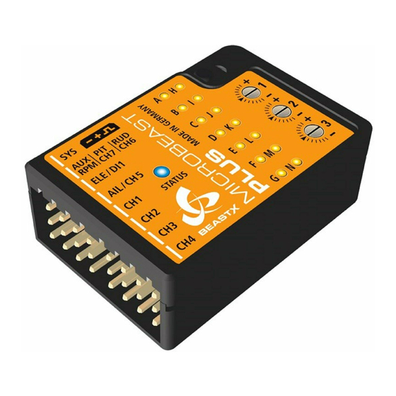
2 MICROBEAST PLUS — What’s that? Figure 1 MICROBEAST PLUS is a gyro system which is used to stabilize and control your flybarless RC Helikopter on all three flight axis. It can be used with many different types of helicopters like 3D aerobatic helis, F3C competition helicopters as well as scale helicopters with 2 or more rotorblades.
-
Page 14
To setup MICROBEAST PLUS there is no need for any additional devices. All you need is your radio system and your helicopter. Thanks to the well proven EasySetup system you can do all the necessary adjustment directly at the device and in very short time. -
Page 15: Additional Guides
Also the quick reference card can give you a good overview for the different menu structures and adjustment procedures that can be performed directly at the device. http://www.beastx.com/download/manual/microbeast/MBPlus_QuickStart_V52_EN.pdf http://www.beastx.com/download/manual/microbeast/MBPlus_QuickReferenceCard_V52_EN.pdf…
-
Page 17: Firmware Version 5.2
4 Firmware version 5.2.x Please note that these instructions are only valid for the MICROBEAST PLUS firmware version 5.2.x! The firmware version can be detected by connecting the device to a computer using the USB2SYS interface (optional) or tablet/smartphone using the BLE2SYS interface (optional) together with the StudioX App.
-
Page 19: Hardware Options
5 Hardware options MICROBEAST MICROBEAST PLUS PLUS Power supply connection Standard servo ports High power input On/Off Switch Casing Plastic Aluminum composite Recommended heli size 250 — 700 550 — 800…
-
Page 21: Software Options
6 Software options Basic firmware ProEdition firmware AttitudeControl Bank switching Upgrade Price 99,- €…
-
Page 23: Safety Notes
Please read the instruction manual thoroughly before the first use of your MICROBEAST PLUS and setup the system carefully according to this manual. Allow sufficient time for the setup procedure and check each step carefully. Watch for a mechanically clean and proper build of your helicopter.
-
Page 24
3,5 volts for a short amount a of time, the system will power off and reboot. In this case a crash of the helicopter is unavoidable. Do not expose the MICROBEAST PLUS system to extreme variations in tem- perature. Before powering up the system, wait some time so that the electronics can acclimatize and any accumulated condensation is able to evaporate. -
Page 25
Contents of the system in consequence. There is no guarantee that the system will always work correctly. Only the pilot is responsible for the control of the helicopter and thus also for the use of the system. Note that the system for technical reasons will not hold the helicopter absolutely to the point. -
Page 27: Box Content And Accessories
8 Box content and accessories This page is a translated version of the page Manuals:MBPlusFblV52:Box Content the translation is 100% complete. https://wiki.beastx.com/index.php?title=Special:Translate&group=page-Manuals% 3AMBPlusFblV52%3ABox+Content&action=page&filter=&language=en https://wiki.beastx.com/./index.php/Manuals:MBPlusFblV52:Box_Content…
-
Page 29: This Is What You Get When Buying The Microbeast Plus
• plastic tool for adjusting the gain dials Figure 21 Please note: MICROBEAST PLUS is usually sold with BASIC firmware. If you like, you can upgrade to PROEDITION firmware later using the StudioX PC software or StudioXm app. Ask your dealer if you need the PROEDITION firmware upgrade installed already.
-
Page 31: This Is What You Get When Buying The Microbeast Plus Hd
• high power connector and on/off switch Figure 22 Please note: MICROBEAST PLUS HD is usually sold with BASIC firmware. If you like, you can upgrade to PROEDITION firmware later using the StudioX PC software or StudioXm app. Ask your dealer if you need the PROEDITION firmware upgrade installed…
-
Page 33: Optional Accessory
USB2SYS Figure 23 USB2SYS connects your MICROBEAST PLUS / MICROBEAST PLUS HD with your computers USB port. With the StudioX Software (available for Windows and macOS) you can easily configure the system, create backups of your settings, load heli presets, upload firmware update file to your unit and much more.
-
Page 34
BLE2SYS is a Bluetooth Smart Interface that allows to connect your MICROBEAST PLUS / MICROBEAST PLUS HD to your smartphone or tablet. With the StudioXm app (available for Android and iOS) you can easily configure the system, create backups of your settings, load heli presets, upload firmware update file to your unit and much more. -
Page 35: Hardware Installation
12 Hardware installation This page is a translated version of the page Manuals:MBPlusFblV52:Hardware Installa- tion and the translation is 100% complete. https://wiki.beastx.com/index.php?title=Special:Translate&group=page-Manuals% 3AMBPlusFblV52%3AHardware+Installation&action=page&filter=&language=en https://wiki.beastx.com/./index.php/Manuals:MBPlusFblV52:Hardware_Installation…
-
Page 37: Attaching Your Microbeast Plus To The Helicopter
13 Attaching your Microbeast PLUS to the helicopter Attach the Microbeast PLUS unit by using one of the provided 3M® gyropads at a prefer- ably low vibrating position on your helicopter such as the gyro platform or receiver platform. You may need to choose another type of mounting pad depending on the vibration pattern of your helicopter.
-
Page 38
Attaching your Microbeast PLUS to the helicopter Figure 36 Pay attention that the edges of the Microbeast PLUS unit are all parallel with the corresponding rotational axes of the helicopter! Especially make sure that the mounting platform is perpendicular to the main shaft! On the other hand it… -
Page 39: Introduction To Microbeast Plus Hd
flyers and extreme 3D pilots and is primarily used in helicopters larger than 500 size that have very power consuming servos installed. By using a low-resistance high-current connector system MICROBEAST PLUS HD makes it possible to use thick power cables for connecting receiver battery or BEC which preserves a virtually loss-free transfer of electric current.
-
Page 40
Introduction to MICROBEAST PLUS HD the switch is not connected MICROBEAST PLUS HD is switched on permanently as soon as the power is connected. Please note: • Using the high power connection port is not a must. You can also use MICROBEAST… -
Page 41: Receiver Connection
Ensure a tight fit of the connectors. The pin board of MICROBEAST PLUS is designed so that the plugs firmly clamp each other when they are fully inserted. Anyhow, especially when using a receiver with single wire output it is possible that connectors are plugged in with no adjacent neighbors.
-
Page 43: Standard Receiver
16 Standard receiver A conventional receiver with multiple servo output connectors is what we consider a ”Stan- dard receiver”. Here you connect each output to one control function of MICROBEAST PLUS by using one connection wire for each function. The 5 control functions (wires) are: Aileron, Elevator, Rudder, Collective pitch and Gyro gain.
-
Page 44
• You must connect all 5 functions/wires to the receiver. When you don’t connect all wires, the system will not finish initialization sequence! • The throttle servo/speed controller is connected to the receiver’s throttle output. Using the headspeed governor function of MICROBEAST PLUS is not possible in combination with a Standard receiver! -
Page 45: Receivers With Single Wire Output (Single-Line Receivers)
A single-line receiver transmits all channels (control functions) by one single connection wire to MICROBEAST PLUS. This is done by packing all channel output data to a digital data paket or by chaining the servo signals. At the moment MICROBEAST PLUS supports the following systems: Multiplex®…
-
Page 46
If there are no other ports left to additionally feed in power, we recommend using the MICROBEAST PLUS HD which comes witch an additional high power input. This reduces wiring resistance and serves todays demands for a robust servo power supply. -
Page 47: Remote Satellite (Spektrum® Dsm/Jr® Dmss/Align® Ibus)
DSM2, Spektrum® DSMX, JR® DMSS and ALIGN® iBus. The remote receiver can be directly connected to the white pin board at the side of MICROBEAST PLUS. Here the receiver will be powered with a stabilized voltage of 3.3 Volts. Alternatively if you own the optional available Spektrum®…
-
Page 48
Remote satellite (Spektrum® DSM/JR® DMSS/ALIGN® iBus) -
Page 49: Spektrum® Srxl2 Receiver
When using a speed controller with BEC, the power will be distributed from [CH5] input of MICROBEAST PLUS to the receiver. Alternatively or additionally you can connect a power supply/second BEC wire/buffering battery to the [SYS] port. It is not recommended to connect power to the receiver directly! In order to connect a receiver with standard servo connectors, i.e.
-
Page 50
This will damage your receiver immediately! Check polarity at least twice before connecting the receiver to MICROBEAST PLUS. It is up to you to make sure polarity is correct. We do not assume any liability in case you do it wrong. -
Page 51: Radio System
20 Radio system This page is a translated version of the page Manuals:MBPlusFblV52:Radio Setup the translation is 100% complete. https://wiki.beastx.com/index.php?title=Special:Translate&group=page-Manuals% 3AMBPlusFblV52%3ARadio+Setup&action=page&filter=&language=en https://wiki.beastx.com/./index.php/Manuals:MBPlusFblV52:Radio_Setup…
-
Page 53: Preparing The Radio System
You can use nearly any transmitter that provides at least 6 channels. By default 5 channels are used for controlling MICROBEAST PLUS and one channel controls the motor. If using additional features like AttitudeControl or RPM Governor a receiver with single wire output and more channels may be useful to have, but this is not a must.
-
Page 54
(except for thrust stick which typically controls collective pitch and motor). Note when using MICROBEAST PLUS you do not directly control the servos of the helicopter. By moving a stick you give a control command to the system which then performs the necessary servo movements to move the helictoper in the commanded direction. -
Page 55
Contents Figure 65 Make sure that the motor in electric models can not start when doing the adjustment work! If the drive battery is used as power supply for receiver, servos and MICROBEAST PLUS disconnect the motor from the ESC. -
Page 57: Spektrum® Dsm2/Dsmx Receiver Binding
[CH5]. To bind a DSMX satellite simply switch on the power supply now. The LED on the receiver and LED H on MICROBEAST PLUS will start to flash. You can bind the transmitter as usual (for more information refer to the instructions of your radio control system).
-
Page 58
Spektrum® DSM2/DSMX receiver binding to use this type of receiver. Remove the bind plug and proceed with the setup as described in the following of this manual. Figure 68 Note: • Decisive for the selection alone is, which type of satellite receiver is plugged in! It is irrelevant which transmission method between the receiver and transmitter is actually used. -
Page 59: Receiver Menu
By default the ”Standard Receiver” is selected as receiver type. So if you’re using this type of receiver and your MICROBEAST PLUS is brand new, you can skip this section as it is already setup correctly! https://wiki.beastx.com/index.php?title=Special:Translate&group=page-Manuals%…
-
Page 61: Preset Function Assignments For Single-Line Receivers
PPM serial signal (SPPM) Pitch Aileron Elevator Rudder Aux [CH6]* Throttle Gyro gain Governor [CH5] (nitro) Futaba® SBus/Sbus2 or BEASTX® FASST compatible receiver Aileron Elevator Throttle Rudder Gyro gain Pitch Aux [CH6]* Governor [CH5] (nitro) Multiplex® SRXL, JR® XBUS Mode B, JETI® UDI…
-
Page 62
Preset function assignments for Single-line receivers Graupner® HOTT SUMD Pitch Aileron Elevator Rudder Aux [CH6]* Throttle Gyro gain Governor [CH5] (nitro) Jeti® ExBus Throttle Aileron Elevator Pitch Rudder Gyro gain Aux [CH6]* Governor [CH5] (nitro) ALIGN®/FlySky® iBus Aileron Elevator Throttle Rudder Gyro gain Pitch… -
Page 63: Adjustment On The Device
25 Adjustment on the device To get into the Receiver menu press the button on MICROBEAST PLUS and hold it down before(!) and while turning on the receiver power supply. The yellow Menu-LEDs start to cycle immediately. When you release the button, Menu LED A will be flashing and the color of the Status LED will indicate the receiver type that is selected at the moment.
-
Page 64: Function Assignment
Status LED will flash in red color. In this case once again make sure your receiver is connected properly to MICROBEAST PLUS, bound to the transmitter and sending out control signals and try again.
-
Page 65
V shape curve) and teach the throttle channel by re-operating the thrust stick at Menu Point G. Now the collective pitch channel is no longer considered as this channel has already been assigned previously and MICROBEAST PLUS will detect and use the throttle channel as actuator for throttle function!</p>… -
Page 66
Adjustment on the device optional to assign and can be skipped. If special features like AttitudeControl or Headspeed Governor are not installed on your device, the specific menu points for assignment will not be accessible at all. • The assignment for Aux [CH6] Output at Menu Point H can be skipped by pressing the button without teaching a channel for this function in case it is not used. -
Page 67: Point N — Throttle Failsafe
(e.g. Spektrum® satellite receiver or Graupner® receiver in „SUMDOF“ mode) • if the connection between MICROBEAST PLUS and receiver gets disconnected • during initialization when the transmitter was not switched on before or was switched on…
-
Page 68
Adjustment on the device Figure 75 noframe During failsafe setting the CH5 Output is enabled and can be controlled by the transmitter channel that is assigned to throttle function. This allows to check your throttle position in reality. When using electric models make sure the motor is disconnected from the ESC or the pinion is removed from the motor, so that it will not drive the model by accident. -
Page 69: Setup With Studiox
26 Setup with StudioX When StudioX is started and your MICROBEAST PLUS was detected by StudioX, click the Control Setup tab to show the adjustment options of RECEIVER MENU. The options you see here are basically similar to the Menu Points you can change directly at the device.
-
Page 70: Function Assignment
Once a channel was assigned, it is no longer available and is ignored by MICROBEAST PLUS for the remaining process. Thus, after learning of the collective pitch function (at Menu Point B) you can enable the throttle function (remove throttle hold or switch to a linear or V shape curve) and teach the throttle channel by re-operating the thrust stick at Menu Point G.
-
Page 71: Throttle Failsafe
• if using a single-line receiver that turns of the single-line signal in case of signal loss be- tween receiver and transmitter (e.g. Spektrum® satellite receiver or Graupner® receiver in „SUMDOF“ mode) • if the connection between MICROBEAST PLUS and receiver gets disconnected…
-
Page 72
Setup with StudioX • during initialization when the transmitter was not switched on before or was switched on too late and the radio link between transmitter and receiver is not established yet Additionally the failsafe position is used by the internal Governor function in case you’re using a helicopter with electric drive system. -
Page 73: Setup Menu (Basic Heli Setup)
MICROBEAST PLUS offers different type of menu structures for different needs of adjust- ment. Before the first flight MICROBEAST PLUS has to be adjusted to your helicopter mechanics and its components. This basic setup is done in the SETUP MENU.
-
Page 75: Adjustment On The Device
28 Adjustment on the device If not already done power up your radio and MICROBEAST PLUS and wait until initial- ization sequence is finished. At first the system will calibrate to the radio system, Menu LEDs H to N will cycle up and down. During this time do not move the sticks on your radio as the system is learning the stick mid positions.
-
Page 76: Button Control
10 seconds, then release. After doing so you will not be able to fly anymore! You have to do all the basic heli setup again and also all the other settings from PARAMETER MENU will be reset!! There are 2 exceptions: https://wiki.beastx.com/./index.php/Manuals:MBPlusFblV52:Setupmenu_M https://wiki.beastx.com/./index.php/Manuals:MBPlusFblV52:Setupmenu_N https://wiki.beastx.com/./index.php/Manuals:MBPlusFblV52:Governormenu_F…
-
Page 77: Stick Control
RECEIVER MENU again. Never fly while MICROBEAST PLUS is in SETUP MENU or any other menu! In this condition the gyro control and the stick controls are disabled.
-
Page 79: Basic Setup With Studioxm
BLE2SYS is also sending on the 2.4GHz band! Also make sure MICROBEAST PLUS is in operation mode! When it is still in one of the adjustment menus the gyro control and the stick controls may be disabled and you will not be able to fully control your helicopter! https://wiki.beastx.com/./index.php/StudioXm/en…
-
Page 81: Setup Menu A — Device Orientation
This page is a translated version of the page Manuals:MBPlusFblV52:Setupmenu A the translation is 100% complete. MICROBEAST PLUS can be mounted in nearly all possible orientations. The only restriction is that the main connection terminal has to point in or against flying direction and the egdes of the unit must be parallel to the rotation axis.
-
Page 83: Adjustment At The Device
31 Adjustment at the device Select the orientation that the device is actually mounted on your heli by choosing the suitable Status LED color. You can switch between the options by briefly moving the rudder stick to one or the other direction. The Status-LED will change the color accordingly.
-
Page 85: Setup With Studioxm
32 Setup with StudioXm Choose the orientation that the device is actually mounted on your heli by choosing the matching type in the app.
-
Page 87: Setup Menu B — Swashplate Frequency
field use. When using a servo that allows a higher frequency as MICROBEAST PLUS offers or that allows a maximum frequency which is not choosable, please select the next lower frequency that is closest to the given frequency or set the frequency with StudioXm PC Software or mobile App.
-
Page 88
SETUP MENU B — Swashplate frequency… -
Page 89: Adjustment On The Device
34 Adjustment on the device To select the desired servo frequency move the rudder stick repeatedly in one direction until the Status-LED lights in the correct color at SETUP MENU point B: Status-LED Swashplate servo frequency purple 50 Hz red flashing 65 Hz 120 Hz blue flashing…
-
Page 91: Setup With Studioxm
35 Setup with StudioXm Choose a preset frequency by clicking one of the provided buttons for Menu Point B (Swashplate frequency) or set a custom frequency by directly changing the value with the dial or buttons.
-
Page 93: Servo Connection
When using a scale helicopter with 90 degrees eCCPM you can connect a second elevator servo to CH7 output on the MICROBEAST PLUS. Note that CH7 only is a signal output, so you must power the servo from elsewhere, i.e. by getting power from the SYS-port or CH5 using a Y-adapter (for + and — only!).
-
Page 95: Setup Menu C — Rudder Pulse Width
If in doubt about the center pulse for your servo use the setting 1520 μs. It is very likely that the servo will work with this pulse length. Also when the servo is rated with 1500 μs center pulse use this setting. There is barely any difference between 1500 and 1520 https://wiki.beastx.com/index.php?title=Special:Translate&group=page-Manuals% 3AMBPlusFblV52%3ASetupmenu+C&action=page&filter=&language=en https://wiki.beastx.com/./index.php/Manuals:MBPlusFblV52:Setupmenu_C…
-
Page 96
There is a relationship between the setting of the rudder servo center pulse length and the (rudder frequency ). For technical reason only special gyro servos with 760µs pulse width can be used with frequencies higher than 333Hz, as standard pulse width would be too long and would not fit into the pulse! https://wiki.beastx.com/./index.php/Manuals:MBPlusFblV5:Setupmenu_D… -
Page 97: Adjustment On The Device
38 Adjustment on the device To select the desired rudder servo pulse width (servo type) move the rudder stick repeatedly in one direction until the Status-LED lights in the correct color at SETUP MENU point C: Status-LED Rudder servo center pulse length purple blue 1520…
-
Page 99: Setup With Studioxm
39 Setup with StudioXm Choose a preset rudder pulse width by clicking one of the provided buttons for Menu Point C (Rudder pulse width) or set a custom pulse width by directly changing the value with the dial or buttons.
-
Page 101: Setup Menu D — Rudder Servo Frequency
field use. When using a servo that allows a higher frequency as MICROBEAST PLUS offers or that allows a maximum frequency which is not choosable, please select the next lower frequency that is closest to the given frequency or set the frequency with StudioXm PC Software or mobile App.
-
Page 102
SETUP MENU D — Rudder servo frequency With high frequencies, some servos run in a jerky manner, especially the fast ones with coreless or brushless servos. This is due to the high update rate that the servo receives. This is not critical and will not impact flight performance. -
Page 103: Adjustment On The Device
41 Adjustment on the device To select the desired servo frequency, move the rudder stick repeatedly in one direction until the Status-LED lights in the correct color. Please note that depending on the rudder servo center pulse width chosen at Menu Point C, you may not be able to select a frequency higher than 333Hz! Status-LED Rudder servo frequency…
-
Page 105: Setup With Studioxm
42 Setup with StudioXm Choose a preset frequency by clicking one of the provided buttons for Menu Point D (Rudder frequency) or set a custom frequency by directly changing the value with the dial or buttons.
-
Page 107: Manuals:mbplusfblv52:Setupmenu E
Keep this in mind when adjusting the tail rotor endpoints. Check the helicopter‘s manual to find out how much tail pitch is useful and where to set end points. https://wiki.beastx.com/index.php?title=Special:Translate&group=page-Manuals% 3AMBPlusFblV52%3ASetupmenu+E&action=page&filter=&language=en https://wiki.beastx.com/./index.php/Manuals:MBPlusFblV52:Setupmenu_E…
-
Page 109: Mechanical Setup Of The Rudder Servo
In the following of this setup step you will be asked to connect the rudder servo to MICROBEAST PLUS. When doing so plug the servo connector into CH4 output at the device. Watch out for correct polarity, the black or brown minus wire must be the clostest to the bottom of the device.
-
Page 110
Mechanical setup of the rudder servo This mechanical adjustment especially is important when using the tail gyro in Normal- Rate mode. If the adjustment was not done properly the helicopter will constantly drift to one side or the other on the rudder axis. When using the tail gyro only in HeadingLock mode this adjustment is not so critical. -
Page 111: Adjustment On The Device
2. Now set the rudder direction of the MICROBEAST PLUS gyro: When you move the rudder stick to the right, the Status LED must light up or flash in blue color. When you move the rudder stick to the left, the Status LED must light up or flash in red color.
-
Page 112
Always set servo direction in the transmitter first, then check the display on the MICROBEAST PLUS or in the software and change the internal control direction if it does not match the real direction. Do not change the internal direction in order to change the servo direction! This is only used for telling the gyro in which direction it must move the servo. -
Page 113: Setup With Studioxm
Stick moved into one direction, deflection not enough Stick moved into one direction, maximum position reached 2. Now connect the rudder servo to [CH4] port of MICROBEAST PLUS as described above and check the rudder direction on the helicopter. If the stick is moving the servo into the wrong direction use the servo reverse function of your transmitter and reverse the rudder channel to set stick control direction correctly.
-
Page 114
Always set servo direction in the transmitter first, then check the display on the MICROBEAST PLUS or in the app and change the internal control direction if it does not match the real direction. Do not change the internal direction in order to change the servo direction! This is only used for telling the gyro in which direction it must move the servo. -
Page 115: Extra Info: Why Setting Stick Endpoints
47 Extra info: Why setting stick endpoints? This ensures that control range of the radio system matches the internal range of MI- CROBEAST PLUS. Later when setting the control style you can adjust how fast your helicopter should turn around the vertical axis. To get reproducable results you have to match your radio to the system!
-
Page 117: Extra Info: How The Gyro Works
48 Extra info: How the gyro works! The gyro always tries to steer in the opposite direction of the rotation that is applied to the helicopter. If you move the helicopter by hand around its vertical axis, the gyro must actuate a rudder servo movement to compensate this rotation.
-
Page 118
Extra info: How the gyro works! Figure 97 When moving the tail to the right by hand (nose of the heli to the left), the gyro will steer to the right, so the tail is pushed back to the left. -
Page 119
SETUP MENU F — Rudder control direction Figure 98 When moving the tail to the right by hand (nose of the heli to the left), the gyro steers to the left and so the tail will move even further! Please note: This only shows an example for the ALIGN T-Rex 500 helicopter. Actually the tail pitch slider may move to a different position on your helicopter. -
Page 121: Setup Menu G — Collective And Cyclic Pitch Mixing (Ccpm)
Deactivate the swashplate mixing in your transmitter or set it to mechanical mixing (which is often called “normal“, “H1“ or ”1 servo“ mixing), so that each stick function only moves one receiver output channel. The swashplate mixing is all done by MICROBEAST PLUS! https://wiki.beastx.com/index.php?title=Special:Translate&group=page-Manuals% 3AMBPlusFblV52%3ASetupmenu+G&action=page&filter=&language=en…
-
Page 122
SETUP MENU G — Collective and cyclic pitch mixing (CCPM) -
Page 123: Adjustment On The Device
50 Adjustment on the device The color and state of the Status-LED shows the currently selected mixing type. To select the desired type tap the rudder stick repeatedly in one direction until the Status-LED lights in the correct color: Status-LED Swashplate mixer purple mechanical…
-
Page 125: Setup With Studioxm
(outputs CH1 and CH2) in case these are not making similar cyclic pitch deflection (Note: You mustn’t change the servo throw in the transmitter as with the transmitter you do not directly control the servos!) https://wiki.beastx.com/./index.php?title=Special:Upload&wpDestFile=SetupGm.png…
-
Page 126
Setup with StudioXm By default the values you see here are preset by the type you’ve chosen in the overview before. Change them as necessary. -
Page 127: Additional Info: What Swash Mixing Is Required For My Helicopter
52 Additional info: What swash mixing is required for my helicopter? Today most helicopters use a 120° swashplate, i.e. all ALIGN T-Rex helicopters as well as SAB Goblin, Mikado Logo, MSH Protos and many more. Mechanical mixing was very common on Thunder Tiger Raptor helicopters and Vario scale or trainer machines but is getting rare today.
-
Page 129: Setup Menu H — Servo Directions
Because of this, the servo reversing in MICROBEAST PLUS is not necessary and not provided when using the mCCPM swash type! SETUP MENU point H will be skipped in this case.
-
Page 131: Adjustment On The Device
54 Adjustment on the device By tapping the rudder stick you can select one servo after another. Every color of the Status-LED is corresponding to a specific servo channel that is indicating its selection by a short up and down move. (You can switch back and forth between the servos as often as you need.) When you tap the aileron stick once, the selected servo will reverse its direction.
-
Page 133: Setup With Studioxm
55 Setup with StudioXm When the adjustment screen appears, set servo direction for each servo as necessary and make sure the pitch is moving correctly as described above. x250px https://wiki.beastx.com/./index.php?title=Special:Upload&wpDestFile=SetupIm.png…
-
Page 135: Setup Menu I — Cyclic Directions
Manuals:MBPlusFblV52:Setupmenu I the translation is 100% complete. At SETUP MENU point I we teach the the control directions to the system, so that it moves the swashplate in the correct direction when trying to control the helicopter. https://wiki.beastx.com/index.php?title=Special:Translate&group=page-Manuals% 3AMBPlusFblV52%3ASetupmenu+I&action=page&filter=&language=en https://wiki.beastx.com/./index.php/Manuals:MBPlusFblV52:Setupmenu_I…
-
Page 137: Adjustment On The Device
2. Now set the internal control direction for the MICROBEAST PLUS gyro: When you push elevator forwards, the Status LED must light up or flash in blue color. When you pull elevator backwards, the Status LED must light up or flash in red color.
-
Page 138
Adjustment on the device In addition you can check the gyro direction by turning the helicopter by hand around its horizontal and longitudinal axis. When turning the heli the gyro must move the swashplate so that the rotor will produce a counter action agains the turn direction. -
Page 139: Setup With Studioxm
2. Now adjust the internal control direction of the MICROBEAST PLUS gyro: When you push elevator forwards, the Status LED must light up or flash in blue color and you should see the label forwards getting blue as well.
-
Page 140
Setup with StudioXm it does not match the real direction. Do not change the internal direction in order to change the servo direction! This is only used for telling the gyro in which direction it must move the swashplate. Be very conscientious when doing this setup step as wrong gyro direction will cause loss of control during takeoff… -
Page 141: Extra Info: Why Setting Stick Endpoints
59 Extra info: Why setting stick endpoints? This ensures that control range of the radio system matches the internal range of MI- CROBEAST PLUS. Later when setting the control style you can adjust how fast your helicopter will roll and tilt. To get reproducable results you have to match your radio to the system!
-
Page 143: Extra Info: How The Gyro Works
60 Extra info: How the gyro works! The gyro always tries to steer in the opposite direction of the rotation that is applied to the helicopter.When tilting the helicopter forwards the swashplate has to move backwards, when tilting the helicopter to the rear, the swashplate has to compensate forward. Same thing applies to the roll axis: when you roll the helicopter to the left the swashplate has to steer right and vice versa.
-
Page 144
Extra info: How the gyro works! Figure 102… -
Page 145: Setup Menu J — Servo Trim
At 0 degrees of pitch the swash driver arms must be horizontal and the linkage balls of the blade grips must be perpendicular to the spindle shaft. Figure 104 Figure 103 https://wiki.beastx.com/index.php?title=Special:Translate&group=page-Manuals% 3AMBPlusFblV52%3ASetupmenu+J&action=page&filter=&language=en https://wiki.beastx.com/./index.php/Manuals:MBPlusFblV52:Setupmenu_J…
-
Page 147: Adjustment On The Device
62 Adjustment on the device 62.1 Separate servo trim Initially the trimming is 0 for all servos. In this case the Status LED will be off when entering Setup Menu Point J. At first, attach the servo horns to the servos in this position. So you will make sure to get roughly equal throws to both directions.
-
Page 148: Deleting The Trimming
Adjustment on the device the swashplate into each direction by tapping or holding aileron or elevator. The collective pitch can be trimmed up and down with the rudder stick. 62.3 Deleting the trimming To reset the trimming and set all positions back to zero, push and hold the button for 10 seconds or more.
-
Page 149: Setup With Studioxm
Trim each servo using the + and — buttons so that the servo horn forms an exact 90 degrees angle with the linkage rod. Then make the mechanical adjustment for the linkages as described above if necessary. x250px https://wiki.beastx.com/./index.php?title=Special:Upload&wpDestFile=SetupHm.png…
-
Page 151: Setup Menu K — Cyclic Throw
If you have problem with finding correct gain settings or overcompensation later in flight, the cause may be found here. To solve this you can change geometry by moving the linkage balls on the servo horns closer to the servo https://wiki.beastx.com/index.php?title=Special:Translate&group=page-Manuals% 3AMBPlusFblV52%3ASetupmenu+K&action=page&filter=&language=en https://wiki.beastx.com/./index.php/Manuals:MBPlusFblV52:Setupmenu_K…
-
Page 152
SETUP MENU K — Cyclic throw center. Status-LED Cyclic throw purple not good blue perfect! -
Page 153: Adjustment On The Device
65 Adjustment on the device Initially the Status LED will be off, the swashplate will be leveled and rotorblades will have 0 degrees of pitch. Attach your pitch gauge to the rotorblade or blade grip, calibrate it to 0 degrees and then tap the rudder stick once. This will move the rotorblades into measuring position.
-
Page 155: Setup With Studioxm
66 Setup with StudioXm Initially the swashplate will be leveled and rotorblades will have 0 degrees of pitch when the cyclic throw adjustment screen opens. Attach your pitch gauge at the rotorblade or blade grip, calibrate it to 0.0 degrees and then click the Measure button. This will move the rotorblade into measuring position.
-
Page 157: Measuring Pitch Without Pitch Gauge
67 Measuring pitch without pitch gauge If your helicopter is too small for attaching a digital pitch gauge or simply in case you haven’t got one, you can use a little trick to measure the pitch anyway. You can calculate the angle from the distance the rotor blades move from zero position.
-
Page 159: Setup Menu L — Collective Pitch
At SETUP MENU point L you set the maximum negative and positive collective pitch for your helicopter. Additionaly you have to make sure that MICROBEAST PLUS is detecting the direction of movement correctly. This especially is important when using the rescue bailout function but has also effect on the normal flying!
-
Page 161: Adjustment On The Device
Always set the servo direction in the transmitter first, then check the display on the MICROBEAST PLUS and change the internal control direction if it does not match the real direction. Do not change the internal direction in order to change the servo direction! This is only used for telling the system in which direction is up and down.
-
Page 163: Setup With Studioxm
Always set the servo direction in the transmitter first, then check the display on the MICROBEAST PLUS and change the internal control direction if it does not match the real direction. Do not change the internal direction in order to change the servo direction! This is only used for telling the system in which direction is up and down.
-
Page 165: What Pitch Is Useful For My Helicopter
finally in what you expect to do with the helicopter. So beginner or scale pilots will not need as much pitch as a 3D aerobatics pilot or high speed flyer. Anyhow, as already mentioned above set the pitch range in MICROBEAST PLUS so that it roughly fits to your helicopter mechanics and its capabilities.
-
Page 167: Measuring Pitch Without Pitch Gauge
72 Measuring pitch without pitch gauge If your helicopter is too small for attaching a digital pitch gauge or simply in case you haven’t got one you can use a little trick to measure the pitch anyway. You can calculate the angle from the distance the rotor blades move from zero position.
-
Page 169: Setup Menu M — Servo Limit
flying in general or it can cause you heli not to have equal rotations rates, accelerate slowly or not being able to reach high rotation rates at all. Status-LED Servo limit purple not good blue perfect! https://wiki.beastx.com/index.php?title=Special:Translate&group=page-Manuals% 3AMBPlusFblV52%3ASetupmenu+M&action=page&filter=&language=en https://wiki.beastx.com/./index.php/Manuals:MBPlusFblV52:Setupmenu_M…
-
Page 170
SETUP MENU M — Servo limit • Always try to give the system as much servo throw as possible and limit as less as possible. Do not use the limit to adjust the pitch or rates or similar, this is not what it is it used for! •… -
Page 171: Adjustment On The Device
74 Adjustment on the device At SETUP MENU point M carefully move pitch, aileron and elevator all at once and into all possible positions and check if there is some point where the servos get jammed. By rudder stick input you can increase/decrease the amount of maximum servo throw/servo limit (left = decrease throw, right = increase throw).
-
Page 173: Setup With Studioxm
Increase/decrease the amount of maximum servo throw/servo limit by using the + and — buttons and the dial. Make sure the value is as high as possible. x250px https://wiki.beastx.com/./index.php?title=Special:Upload&wpDestFile=SetupLm.PNG…
-
Page 175: Headspeed Governor
76 Headspeed Governor This page is a translated version of the page Manuals:MBPlusFblV52:Governor and the translation is 100% complete. https://wiki.beastx.com/index.php?title=Special:Translate&group=page-Manuals% 3AMBPlusFblV52%3AGovernor&action=page&filter=&language=en https://wiki.beastx.com/./index.php/Manuals:MBPlusFblV52:Governor…
-
Page 177: What’s A Headspeed Governor
For helis with combustion engine you don’t need to buy a separate governor device anymore, with MICROBEAST PLUS you already have it on your heli.
-
Page 179: Hardware Installation
78 Hardware installation Thus the RPM Governor of MICROBEAST PLUS can be used, the system must be able to detect the motor speed. This is done with the help of a rpm sensor that must be attached to the sensor input of MICROBEAST PLUS. For models with nitro/gas engines usually sensors are used that determine the speed signal magnetically or optically.
-
Page 180: Electric Drive System With Rpm Signal Output From The Speed Controller
When a speed controller is used that provides a rpm signal output you can alternatively use the [RPM] sensor input on the front connection board of MICROBEAST PLUS (lowest pin of the tripple signal input). (RPM sensors can‘t be connected here as this pin header does not provide any power supply!) The speed controller‘s signal input wire is plugged…
-
Page 181: Combustion Drive System (Nitro/Gas)
Combustion drive system (nitro/gas) 78.3 Combustion drive system (nitro/gas) Particularly when using sensors for combustion engines check for correct polarity of the sensor power supply on the adapter cable BXA76401. Here commonly sensors are used that are designed for governor systems from other manufacturers and therefore have a special pin assignment.
-
Page 183: Activating The Governor Function
79 Activating the governor function This page is a translated version of the page Manuals:MBPlusFblV52:Setupmenu N the translation is 100% complete. https://wiki.beastx.com/index.php?title=Special:Translate&group=page-Manuals% 3AMBPlusFblV52%3ASetupmenu+N&action=page&filter=&language=en https://wiki.beastx.com/./index.php/Manuals:MBPlusFblV52:Setupmenu_N…
-
Page 185: Adjustment On The Device
— select this option if your helicopter is powered by an electric motor and an electric speed controller is plugged into output [CH5] of MICROBEAST PLUS. The device reads the speed sig- nal from the speed controller or a phase sensor and controls the rotor speed accordingly.
-
Page 187: Setup With Studiox
81 Setup with StudioX When StudioX/StudioXm has connected to your MICROBEAST PLUS, in the device overview main screen click the ”Governor setup” button. Under ”Governor Basic Setup” you can enable the governor function by choosing either ”Electric” or ”Nitro/Gas Heli depending on the type of helicopter/drive system you’re using.
-
Page 189: Sensor Test Routine
Once the motor is running the Status-LED on the MICROBEAST PLUS should light up in red color. Please note that the control range of throttle is crucial! Usually the throttle endpoints of the transmitter are fixed by an initial programming of the speed controller.
-
Page 190
Thus the Governor of MICROBEAST PLUS can operate correctly, the motor speed should increase as linear as possible when the stick is moved and there should be no ranges in that the motor speed does not change. -
Page 191
Combustion drive system (nitro/gas) If the Status-LED on the MICROBEAST PLUS does not light up as described please double check the wiring. Particularly pay attention whether the power wires of the sensor are of correct polarity (on some sensors the wire colors do not match the usual standard!). -
Page 193: Motor Start Position
Also in this case move the throttle stick to the point at which the motor is just before to start, so that MICROBEAST PLUS can determine the effective throttle range correctly. With a nitro/gasser model bring the throttle stick to idle position or a slightly increased idle position (not „motor off“!)
-
Page 195: Adjustment On The Device
84 Adjustment on the device When setting the low throttle position make sure the Status-LED lights up in blue color (both electrical as well as nitro). This means that a new valid throttle position has been detected. If the Status-LED lights up in red then the throttle stick is too close to the throt- tle stick center position.
-
Page 197: Setup With Studiox
85 Setup with StudioX When performing the setup with StudioX, you will see the actual internal throttle value in the app. Usually this will be something around +-1000 when the throttle is at lowest position. Push the SET button in order to store this value as lowest throttle value for the headspeed governor.
-
Page 199: Full Throttle Position
(we expect that your maximum stick position actually indicates the maximum throttle position of your ESC in case your ESC is setup correctly!). Otherwise there are no differences between the modes „electric“ and „nitro“. https://wiki.beastx.com/index.php?title=Special:Translate&group=page-Manuals% 3AMBPlusFblV52%3AGovernormenu+C&action=page&filter=&language=en https://wiki.beastx.com/./index.php/Manuals:MBPlusFblV52:Governormenu_C…
-
Page 201: Adjustment On The Device
C by a brief push of the button without changing the throttle position when performing subsequent adjustments in Setup menu or Governor setup menu. Conversely this means that you need to move the throttle stick at menu point C at least once to change the current full throttle position! https://wiki.beastx.com/./index.php/Manuals:MB_Plus:Governormenu_B/en https://wiki.beastx.com/./index.php/Manuals:MB_Plus:Governormenu_B/en…
-
Page 203: Setup With Studiox
88 Setup with StudioX When performing the setup with StudioX, you will see the actual internal throttle value in the app. Usually this will be something around +-1000 when the throttle is at maximum position. Push the SET button in order to store the value shown as maximum throttle value for the headspeed governor.
-
Page 205: Governor Menu D — Setting Up The Transmitter
Governor off = off, Autorotation = purple, Gov active = red or blue (= max. RPM) When performing the setup with StudioX, you can directly read from the app in real-time what your activation points are and what your switch on the radio does! https://wiki.beastx.com/index.php?title=Special:Translate&group=page-Manuals% 3AMBPlusFblV52%3AGovernormenu+D&action=page&filter=&language=en https://wiki.beastx.com/./index.php/Manuals:MBPlusFblV52:Governormenu_D…
-
Page 207: How To Control The Governor
When setting a speed higher than minimum, MICROBEAST PLUS will speed up the rotor smoothly and ensure that the demanded rotor speed is kept constant throughout the flight.
-
Page 208
How to control the Governor Figure 114 Figure 115 Figure 116… -
Page 209
Electric Governor In electric mode the adjustable throttle range is 4200rpm/min. The lowest rotor speed that can be set is 800rpm/min, the maximum speed is 5000rpm/min. To enable autorota- tion bail out mode the throttle must be set to a value between 5% and 15%. Throttle position (scale depending on Rotor speed… -
Page 210: Nitro Governor — With Separate Control Channel
Governor is set at the momement. In respect to this please note that MICROBEAST PLUS will be set to Autorotation bail out mode if the Governor was activated once and the throttle channel is brought back below 25%.
-
Page 211
Nitro Governor — with separate control channel Figure 117 Figure 118 Figure 119… -
Page 212
How to control the Governor Throttle position (scale depending on trans- Status-LED mitter) 100% +100 off (= Manual control) red or blue (= RPM control) Manual control/ Autorotation -100 Rotor speed Governor channel 3000 +100 2870 2740 2605 2470 2340 2210 2080 1950… -
Page 213: Nitro Governor — Simple Mode
MICROBEAST PLUS will always see the same throttle value. So the preset headspeed will stays the same and does not change when moving throttle stick.
-
Page 214
How to control the Governor Figure 120 Figure 121 A third flight mode can be used for performing autorotation maneuvers: Here the throttle channel must be set to a constant value close below center position (between 40% and 50%). When you switch to this position once the governor was active, the throttle servo will be moved to the idle position set at menu point B. -
Page 215
Nitro Governor — simple mode Figure 122 noframe Throttle posi- tion Rotor speed Status-LED (scale depend- ing on trans- mitter) 100% +100 3000 blue 2750 2500 2250 2000 1750 1500 1250 1000 Manual control or Autorotation purple Manual control off -100… -
Page 216
How to control the Governor… -
Page 217: Governor Menu E — Throttle Signal Divider
A). Each time a magnet passes the sensor the Status-LED will light up in blue color there, i.e. when you turn the clutch bell by hand. So you simply count how often the Status-LED lights up during one rotation. Then this is the divider you have to setup. https://wiki.beastx.com/index.php?title=Special:Translate&group=page-Manuals% 3AMBPlusFblV52%3AGovernormenu+E&action=page&filter=&language=en https://wiki.beastx.com/./index.php/Manuals:MBPlusFblV52:Governormenu_E…
-
Page 219: Adjustment On The Device
92 Adjustment on the device At GOVERNOR MENU point E the currently selected division factor is represented by the color of the Status-LED. Use the rudder stick to switch between options. Status-LED RPM Divider off no division 2 motor poles (electric) or 1 magnet (nitro) purple flashing 4 motor poles (electric) or 2 magnets (nitro) purple…
-
Page 221: Setup With Studiox
93 Setup with StudioX In StudioX simply enter the rpm divider using the push buttons.
-
Page 223: Governor Menu F, G & H — Main Gear Ratio
Manuals:MBPlusFblV52:Governormenu F and the translation is 100% complete. The Governor of MICROBEAST PLUS in general calculates with the rotor head speed of the helicopter. So as shown at the transmitter setup step of GOVERNOR MENU you can preset the desired head speed very easily and MICROBEAST PLUS will try to maintain this headspeed as close as possible.
-
Page 225: Adjustment On The Device
95 Adjustment on the device To set the gear ratio on the device you have to adjust three menu points in a row. Menu point F sets the number of gear ratio before the decimal point, menu points G and H specify the first two decimal places.
-
Page 226
Adjustment on the device Menu point G Menu point H Status-LED Status-LED blue flashing purple flashing blue flashing purple blue flashing red flashing blue flashing When a custom gear ratio was set using StudioX or StudioXm the Status LED will be off at menu point F. -
Page 227: Setup With Studiox
96 Setup with StudioX With StudioX simply enter your gear ratio in the app. Here we also added a calculator for single stage main drive systems. Enter your main gear tooth count and pinion size to easily calculate your main gear ratio. This can be directly stored then.
-
Page 229: Parameter Menu A — Quick Trim
flight mode is not provided as we think it’s not necessary. Never use the trim functions of your remote control! MICROBEAST PLUS will see trim as a control command to turn the heli and not as servo trim. So using the trim on your transmitter will result in a constant rotational movement (if you feel you have such effect even when sticks are perfectly centered and all trims are zero, it may…
-
Page 231: Adjustment At The Device
98 Adjustment at the device For the Quick Trim adjustment you have to enter PARAMETER MENU point A. To do so briefly push the button when in operation mode, so that the yellow Menu LED next to A will start flashing quickly (do not hold the button too long, as this will enter SETUP MENU point A which is shown by a solid lit up LED A).
-
Page 232: Reset Adjustment
Make sure the heli is running smooth and free of vibrations and make sure the MICROBEAST PLUS unit is perfectly aligned to the rotation axis of the helicopter (otherwise the axis will be cross connected together and the calculation of the artificial horizon will not match the real…
-
Page 233: Adjustment With Studiox
99 Adjustment with StudioX When StudioX has connected to your MICROBEAST PLUS, in the device overview main screen click the ”Parameter” button. The topic ”Quick Trim” provides adjustment buttons to change the trim values for aileron, elevator, rudder and also collective.
-
Page 235: Parameter Menu B — Control Style
This includes the maximum rotation rate of the helicopter as well as how sensitive MICROBEAST PLUS will react to stick inputs for aileron, elevator and rudder around the stick centre (Stick expo).
-
Page 237: Adjustment At The Device
101 Adjustment at the device The control style is set at PARAMETER MENU point B at the device (to enter this menu point briefly push and hold the button from operation mode, so Menu LED A flashes, then again brifly push the button so Menu LED B flashes). The choice is done by moving the rudder stick in one direction until the LED indicates the desired color and state.
-
Page 238
When using predefined control behaviors other than ”transmitter” we do not recommend to additionally adjust control curves (Expo/Dual rates) in your transmitter as this will indefinably mix the preset curves of MICROBEAST PLUS with the curves of the transmitter! Anyhow, if you only make small adjustments (e.g. slightly increasing the throw to increase rotation rate) this should be no problem. -
Page 239: Setup With Studiox
102 Setup with StudioX When StudioX has connected to your MICROBEAST PLUS, in the device overview main screen click the ”Parameter” button. Click the ”Next” button once in order to change to the topic ”Bank 1 — Control style”. Here you see the currently used maximum rotation rates and expo values for each control function aileron, elevator and rudder.
-
Page 241: Parameter Menu — Special Parameters C To K
flight characteristics of the helicopter to suit your personal preferences. Normally for the first flight you don‘t need to make any adjustments here. https://wiki.beastx.com/index.php?title=Special:Translate&group=page-Manuals% 3AMBPlusFblV52%3AParametermenu&action=page&filter=&language=en https://wiki.beastx.com/./index.php/Manuals:MBPlusFblV52:Parametermenu…
-
Page 243: Adjustment At The Device
When using the bank switching feature (only with PROEDITION firmware) you can only change the settings for bank 1 using the LED menu of MICROBEAST PLUS. The parameters for banks 2 and 3 must be set in the StudioX software/StudioXm app. When…
-
Page 245: Setup With Studiox
105 Setup with StudioX Please note that editing parameters is only possible when the device has initialized completely. So as long as the system is not in operation mode the button to open the ”Parameters” section is greyed out. If it does not pass initialization sequence check the device status shown in the middle of the screen.
-
Page 247: Parameter Explanation
106 Parameter explanation 106.1 Speed flight stability (Point C) When in fast forward flight apply jerky collective pitch inputs to test this parameter. The helicopter should mainly remain in its horizontal flight path during climbing and descend- ing. If the nose of the helicopter is pitching up and down heavily like a swimming dolphin, increase the setting to compensate for this effect.
-
Page 248
Parameter explanation transmitter. If the value is set too low, pirouettes will be inconsistent during fast forward flight or in crosswind conditions and the helicopter will slowly drift on the vertical axis when in stationary hovering flight with crosswinds. If on the other hand the setting is too high, the tail gyro will respond delayed to fast directional changes and the rudder stick control feels very inprecise. -
Page 249: Stick Deadzone (E)
This makes it difficult to have precise hovering as it is hard to find a stick position at which no input is sent to MICROBEAST PLUS. This can be very dangerous as it may cause the helicopter to tip over when trying to take off…
-
Page 250: Torque Precompensation/Revomix (F)
This method of torque precompensation (RevoMix) relieves the tail control loop and improves the tail performance, especially when using MICROBEAST PLUS on helicopters with insufficient tail authority and/or extreme motor torque (e.g. overpowered electric helicopters) where the tail does blow out for a short moment when applying a sudden collective or cyclic input.
-
Page 251: Cyclic Response (G)
H (servo trim)! 106.5 Cyclic response (G) With point G can be set how aggressive the MICROBEAST PLUS responds to cyclic control commands (roll and pitch). This can reduce the usual uniform and linear control feeling of flybarless systems and approach it to the feeling of a flybared helicopter.
-
Page 252: Pitch Boost (H)
Parameter explanation Status-LED Cyclic response red flashing slightly increased increased blue flashing high blue very high 106.6 Pitch boost (H) PARAMETER MENU point H allows you to setup the collective pitch boost function. This function causes that the faster you move the thrust stick, the more additional collective pitch will be exposed.
-
Page 253: Throttle Response (I)
Slow rampup speed (J) 106.7 Throttle response (I) Use PARAMETER MENU point I to change the response of the internal Governor control. This determines how fast and how far the system will open the throttle when the rotor speed changes. Ideally the response is set as high as possible. If it is too low, the main rotor will speed up in unloaded conditions as the system reduces throttle not quick enough.
-
Page 254: Fast Rampup Speed (K)
Parameter explanation Status-LED Slow rampup speed purple 50 rps red flashing 100 rps 200 rps blue flashing 300 rps blue 400 rps With the StudioX software/StudioXm App you have the option to disable the softstart feature, which will set the spool up rate to ”0”. This is necessary when using a speed controler with built-in soft start feature (but without headspeed governing!).
-
Page 255
Fast rampup speed (K) When using a very fast rampup speed in consequence the throttle will be opened very quick. Especially when recovering from an autorotation maneuver this can cause the rotor blades to fold in or will damage the main gear. So only increase the value stepwise and with care. -
Page 257: Gain Settings
107 Gain settings This page is a translated version of the page Manuals:MBPlusFblV52:Gains and the translation is 100% complete. https://wiki.beastx.com/index.php?title=Special:Translate&group=page-Manuals% 3AMBPlusFblV52%3AGains&action=page&filter=&language=en https://wiki.beastx.com/./index.php/Manuals:MBPlusFblV52:Gains…
-
Page 259: Tail Gyro
108 Tail gyro Gyro gain and operation mode The tail gyro system of MICROBEAST PLUS helps to keep the helicopter’s tail in position while flying around. It makes the rudder only react to stick inputs but not to external effects. Before the first flight, you have to set the correct amount of gyro gain in order to adapt the reaction of the gyro system to your specific helicopter model.
-
Page 260
Tail gyro When setting up the system for the first time, start with medium gain in HeadingLock mode. Then readjust the gain as necessary: Low gain will cause the rudder control feel weak, the tail will break out on collective pitch inputs and it will stop with overshoots. -
Page 261: Cyclic Adjustment
109 Cyclic adjustment The control loop for the cyclics depends on two major parameters: Cyclic gain and Cyclic feed forward. Cyclic gain In general the higher the gain, the harder the helicopter will stop after cyclic moves and the more stable and exact the helicopter will fly. But if the gain is too high, the helicopter will tend to oscillate at high frequency especially on the elevator axis.
-
Page 262
. It is not recommended to increase the feed forward in this case! Although it may produce a quicker servo movement and more direct stick feel at first glance, you will get negative effects on overall performance as described above. https://wiki.beastx.com/./index.php/Manuals:MBPlusFblV5:Setupmenu_L/en https://wiki.beastx.com/./index.php/Manuals:MBPlusFblV5:ControlStyle/en https://wiki.beastx.com/./index.php/Manuals:MBPlusFblV5:ControlStyle/en https://wiki.beastx.com/./index.php/Manuals:MBPlusFblV5:Parametermenu/en… -
Page 263: Tail Gyro
The other parameters mentioned above can be set by turning the dials on the device into a specific position. To adjust the dials please only use the supplied plastic BEASTX adjustment tool to prevent damage to the dials! Figure 128 noframe 110.1 Tail gyro…
-
Page 264: Cyclic Adjustment
Adjustment at the device While adjusting the gain or after initialization sequence was finished, the current amount of gain is displayed by one of the menu LEDs for about 10 seconds: When the gain channel is centered, this will correspond to 0% gain indicated by LED A. The maximum adjustable tail gain is 100% and will correspond to LED N.
-
Page 265
Cyclic adjustment Dial 2: Cyclic feed forward Factory setting of dial 2 is horizontal which provides a good setup in most cases. Turn dial 2 clockwise to increase the cyclic feed forward. This will cause more cyclic stick input going directly to aileron and elevator on the swashplate. Decreasing the direct stick feed forward will do the opposite. -
Page 267: Setup With Studiox
StudioX app independant for all three flight modes. The dials on the device have no effect in this case. The auxiliary channel for adjusting the gyro gain is used to switch between banks (flight modes) instead of adjusting the gyro gain (see the page Bank Switching for more detailed information). https://wiki.beastx.com/./index.php/Manuals:MBPlusFblV52:BankSwitch/en…
-
Page 269: Attitudecontrol
100% complete. Please note that AttitudeControl is an optional feature. It is only available on devices with MICROBEAST PLUS ProEdition firmware installed. You can buy this optional update from the freakware Webshop and flash the ProEdition firmware to your device using the StudioX Software/App.
-
Page 271: What Is Attitudecontrol And How To Use It
113 What is AttitudeControl and how to use it Basically what AttitudeControl does is leveling your helicopter by the flip of a switch or press of a button. There are different options on how the helicopter will be leveled which can be selected in PARAMETER MENU.
-
Page 272: Activating Attitudecontrol In Flight
What is AttitudeControl and how to use it ticotcs. As you can override the AttitudeControl by adding some cyclic stick input even you could let AttitudeControl activated for a longer time, so the system guides you like a helping hand. I.e. when you make a front flip you only have to concentrate on giving correct collective pitch input.
-
Page 273
60. Just don’t go too high from the beginning as this can cause a very hard and abrupt reaction of the system, maybe harder than your helicopter likes! The LED display on the MICROBEAST PLUS shows whether AttitudeControl is active and how high the gain is. When the switch channel is moved into the OFF direction the Menu-LED A will light up and flash. -
Page 274
What is AttitudeControl and how to use it Gyro channel (combined switch mode) As an alternative to using a separate channel for activating the AttitudeControl you can also use the gyro gain channel, i.e. when you only have a 6-channel transmitter or when using a receiver with standard wiring (here we simply can’t connect an additional channel physically). -
Page 275: Functional Test Of Attitudecontrol
When activating AttitudeControl you should be able to see an immediate impact on the swashplate control: If the heli is tilted to one side, MICROBEAST PLUS permanently steers the swashplate opposed to the inclination. In the region around horizontal position…
-
Page 276
What is AttitudeControl and how to use it Figure 141 Figure 142 When AttitudeControl is deactivated on the other hand, the swashplate will always be moved back to neutral position (perpendicular to main rotor shaft) as soon as the helicopter is standing still for a few seconds, independant of the current leveling. -
Page 277: Flying With Attitudecontrol
Flying with AttitudeControl Figure 143 In the modes rescue bailout and 3D — Mode the system will also control the collective pitch when it tries to rotate the heli back into level position. Here the maximum amount of pitch is determined by the setting AttitudeControl Pitch in PARAMETER MENU (Point M).
-
Page 278: Fine Tuning Of Attitudecontrol
What is AttitudeControl and how to use it switch. The helicopter should continue to hover in approximately the same position. Now give some aileron or elevator stick input and release the stick when the helicopter reached some oblique position. AttitudeControl should bring the helicopter back to the horizontal position more or less rapidly.
-
Page 279
Fine tuning of AttitudeControl • In case the helicopter is not aligned horizontally as desired with active AttitudeControl, i. e. drifts to one side in hovering, the artificial horizon can be readjusted. This is done in Quicktrim Menu at PARAMETER MENU point A or by changing the trim with the StudioX software or StudioXm app. -
Page 281: Adjustment At The Device
114 Adjustment at the device If not already done enter PARAMETER MENU by pushing the button briefly when the device is operational, so that the Menu LED next to point A starts to flash. Then repeatedly press the button to skip to Menu LED (menu point) L. At PARAMETER MENU point L you can choose between five different AttitudeControl operation modes.
-
Page 282
Adjustment at the device Hovering pitch At PARAMETER MENU point M the collective pitch will move to the set hovering position. As described above this will be used to keep the heli in hovering position (when using an AttitudeControl mode with pitch). Ideally the pitch angle is exactly as large as it is necessary to maintain a stationary hovering flight without ascending or descending. -
Page 283
Fine tuning of AttitudeControl… -
Page 285: Setup With Studiox
115 Setup with StudioX When StudioX/StudioXm has connected to your MICROBEAST PLUS, in the device overview main screen click the ”Parameter setup” button. Then click the ”Next” button repeatedly until you reach the screen ”Bank 1 — AttitudeControl” or directly go to this options screen using the box on top.
-
Page 286
Setup with StudioX that you’ve set the hovering pitch as good as possible. But, for examply, when you’ve set more pitch in order to achieve the helicopter gaining height when AttitudeControl is active, this may not cause the helicopter to turn on spot properly. Pitch boost The option ”Pitch boost”… -
Page 287: Bank Switching (Optional)
116 Bank Switching (optional) This page is a translated version of the page Manuals:MBPlusFblV52:BankSwitch the translation is 100% complete. https://wiki.beastx.com/index.php?title=Special:Translate&group=page-Manuals% 3AMBPlusFblV52%3ABankSwitch&action=page&filter=&language=en https://wiki.beastx.com/./index.php/Manuals:MBPlusFblV52:BankSwitch…
-
Page 289: Bank Switching — What’s That
117 Bank Switching — What’s that? With Bank Switching you can change between 3 different parameter sets in flight, instead of using only one fixed parameter set. This allows to adapt the system to different flight conditions or different rotorhead speeds, i.e. when hovering, cruising, speed flying, landing and so on.
-
Page 291: Usage Instructions
118 Usage instructions When Bank Switch is activated all parameters have to be set in the software. This also includes the gains that usually are set with the 3 dials on the device as well as the tail gyro gain. There is one exception: the AttitudeControl gain can be still controlled by a separate switch channel.
-
Page 292
… and use the flightmodes to control the gyro channel. Set the As already mentioned use the servo monitor and the display on the values to select banks for each flight mode as necessary. device to check whether everything is working as expected. https://wiki.beastx.com/./index.php/Manuals:MBPlusFblV5:AttitudeControl/en… -
Page 293
Fine tuning of AttitudeControl • When using bank switching please be absolutely sure which banks you’re using in flight and which are the banks you can choose from. When you do not need a bank either make sure that you can’t activate it on the transmitter or copy all parameter values from another bank to this bank, so you will not switch to an unwanted condition by accident. -
Page 295: Setting Bank Switching With Studiox
119 Setting Bank Switching with StudioX When StudioXm has connected to your MICROBEAST PLUS in the device overview main screen click the ”Parameter” button. Then click the ”Next” button repeatedly until you reach the screen ”Bank 1 — Gains” or directly go to this options screen using the box on top.
-
Page 297: Reset To Default Settings
This brings all parameters and settings back to the default values as mentioned in the man- ual and shown on the MICROBEAST PLUS quick reference card (marked with a * there). Please note: The factory reset will not change your receiver settings (receiver type, function assignments, failsafe settings).
-
Page 299: Performing Factory Reset At The Device
A to N. This shows factory reset was performed. The system will exit SETUP MENU when you release the button. Now all settings are set to default and you have to perform the Basic Setup again, in order to fly the helicopter. Figure 159 https://wiki.beastx.com/./index.php/Manuals:MBPlusFblV5:Setupmenu_intro/en…
-
Page 300
Performing factory reset at the device… -
Page 301: Factory Reset With Studiox
You will find the reset option by choosing ”Backup/Restore” from the overview screen in StudioX (which opens when connection is established to your MICROBEAST PLUS). From there click the ”Next” button two times or directly choose ”Factory reset” from the selection box above to open the reset screen.
-
Page 302
Factory reset with StudioX Figure 161 Click the ”Reset” button and confirm the question ”Are you really sure?”. Now all settings are set to default and you have to perform the Basic Setup again, in order to fly the helicopter. https://wiki.beastx.com/./index.php/Manuals:MBPlusFblV5:Setupmenu_intro/en… -
Page 303: Information About Firmware Versions
100% complete. The software that is installed on your MICROBEAST PLUS controller is what we call a ”firmware”. This firmware can be updated (i.e. for improvements, fixes, new features, …) by downloading a file from the internet and flashing this on the device. To distinguish between firmware files each firmware has a unique version number ”X.Y.Z”…
-
Page 305: Reading The Current Firmware Version
Status LED goes off and the hardware version ”X.Y” of this MICROBEAST PLUS device is displayed. Press the button for a last time to leave the version display and to view the running light for status information.
-
Page 306
Reading the current firmware version pressed once while initialization takes place. To display ”Z” all LEDs A — N are used. Data version The data version consists of two values ”X.Y” which are displayed at the same time through menu LEDs A — G for ”X” and H — N for ”Y”. Hardware version The hardware version consists of two values ”X.Y”… -
Page 307: Studiox Software And Mobile App
100% complete. StudioX / StudioXm is the app that allows to fully configure your MICROBEAST PLUS, Spektrum AR7210BX and NANOBEAST. You can use it to do all the configuration from the computer or smartphone, to backup settings, load preconfigured setups and do a lot more.
-
Page 309: Windows Pc/Mac And Usb2Sys Computer Interface
The file is included in the StudioX installation folder. Also you can get this from the Microsoft website or by using the Windows Update functionality. To connect your BEASTX device to the computer you need one of the following USB interfaces:…
-
Page 310
Windows PC/mac and USB2SYS computer interface BEASTX SPEKTRUM RCWARE RX2SIM USB2SYS interface SPMA3030 interface Wireless Multi-Sim Adapter with USB2SYS interface emulation After installation of the StudioX software bundle, Windows should install the correct drivers when the USB2SYS / SPMA3030 interface is plugged in the PC for the first time. When… -
Page 311: Connecting The Usb2Sys With Your Beastx Device
126.2 Connecting the USB2SYS with your BEASTX device All BEASTX gyros come with a serial communication port which typically is marked with the letters SYS. Connect the servo wire coming from your USB interface to this port. Make sure to connect the wire in correct polarity on both sides! Figure 169 When using the USB2SYS interface you have to power the device with a separate power supply, i.e.
-
Page 312
Windows PC/mac and USB2SYS computer interface To configure and update your BLE2SYS bluetooth LE adapter with StudioX connect it with the USB2SYS interface or RX2SIM wireless simulator interface to the computer. Using the USB2SYS you must power the device with an external power supply connected to a Y-harness. -
Page 313: Smartphone/Tablet And Ble2Sys Bluetooth Interface
Note this may produce extra costs when using your mobile data connection! To connect your BEASTX controller with your smartphone/tablet the BLE2SYS bluetooth smart interface is required. This is plugged into your device’s SYS port and is used to establish a wireless communication to the phone.
-
Page 314
Smartphone/tablet and BLE2SYS bluetooth interface… -
Page 315: Basic Functionality
128 Basic functionality This page is a translated version of the page StudioXm:Overview and the translation is 100% complete. https://wiki.beastx.com/index.php?title=Special:Translate&group=page-StudioXm% 3AOverview&action=page&filter=&language=en https://wiki.beastx.com/./index.php/StudioXm:Overview…
-
Page 317: Beastx Flybarless System
So check your phone settings in this case. Then connect the USB2SYS interface to the [SYS] port of your BEASTX device and power everything up. Click CONNECT to load the data from your device and to enter configuration menus.
-
Page 318: Overview Screen
BLE2SYS button above the device selection box.) 129.2 Overview screen When connection to your BEASTX device is established, wait until the data is loaded from the device and initialization sequence is finished. At first the system will calibrate to the radio system, Menu LEDs H to N will cycle up and down at the device (MICROBEAST PLUS/AR7210BX) and you can read Radio init in the opening overview screen.
-
Page 319: Ble2Sys Configuration
BLE2SYS to a USB2SYS computer interface using a Y-harness and powering with a receiver battery over the second line (as shown earlier Then just click ”Connect” and open the com port as you would connect to a BEASTX gyro. 130.1 Device Name You can set a custom device name (maximum length 11 digits) by changing the name in the line on top of the screen, i.
-
Page 320: Change Pin Code
”Firmware Update” button. So obviously when you click that button you will be able to upload latest firmware updates to your BLE2YS interface (if necessary). The update procedure is not different to any other BEASTX device and is described in the section Firmware Update…
-
Page 321: Presets/Backup/Restore/Reset
131 Presets/Backup/Restore/Reset This page is a translated version of the page StudioXm:BackupRestore and the translation is 100% complete. https://wiki.beastx.com/index.php?title=Special:Translate&group=page-StudioXm% 3ABackupRestore&action=page&filter=&language=en https://wiki.beastx.com/./index.php/StudioXm:BackupRestore…
-
Page 323: Preset Helicopter Settings
(i. e. servos, ESC, …) you can load the preset for your helicopter to your BEASTX flybarless device. So it is not necessary to go through the basic setup routine as your device will be readily setup by loading the preset. Anyhow, you must make sure your radio setup is done properly and that all control commands on the radio are working as expected.
-
Page 325: Backup/Restore
133 Backup/Restore With StudioX you can save your current device settings and load them to your device again, i. e. when you like to test the effect of some parameters and you want switch back to the former setup. With the StudioX software for PC and macOS it is also possible to export those backups to the computer’s file system.
-
Page 326
Backup/Restore Click Figure 181 Figure 180 will find the new restore point in the selection box in the middle of the screen. ”Create” to create a new restore point which saves your settings. Choose it to see all the details and in order to reload or export it. Figure 182 The informations about the restore point will be filled out automatically with date, serial number, helicopter name and other informations. -
Page 327
Firmware update Select Choose Figure 184 the destination folder and enter a filename. The data will be saved with ending ”.rsp”. Figure 183 the restore point you like to save to the file system and click ”Export Restore- point”. Import a restore point from the file system Click Figure 185 ”Import Restorepoint”… -
Page 328
Backup/Restore… -
Page 329: Reset All Settings
You will find the reset option by choosing ”Backup/Restore” from the overview screen in StudioX (which opens when connection is established to your BEASTX device). From there click the ”Next” button two times or directly choose ”Factory reset” from the selection box above to open the reset screen.
-
Page 331: Firmware Update
135 Firmware update This page is a translated version of the page StudioXm:FirmwareUpdate and the trans- lation is 100% complete. https://wiki.beastx.com/index.php?title=Special:Translate&group=page-StudioXm% 3AFirmwareUpdate&action=page&filter=&language=en https://wiki.beastx.com/./index.php/StudioXm:FirmwareUpdate…
-
Page 333: Introduction
136 Introduction StudioX/StudioXm allows to directly flash firmware files to your BEASTX device using the USB (StudioX for PC/Mac) or bluetooth (StudioXm for smartphones) connection. The update process is similar to all our devices so it will be shown here for MICROBEAST PLUS exemplarily.
-
Page 335: Freakware Network
137 freakware Network The firmware files must be downloaded from the freakware network webserver. So for the update process it is necessary that your computer or mobile device serves an internet connection. Please note that especially when using mobile data this may produce costs! We recommend to not use the mobile network and just do the update process at home where you have (free) wifi.
-
Page 337: Update Procedure
files for your device. It is recommended to always use the latest/highest firmware version. Firmware files marked as BASIC will provide the standard firmware that usually comes with your MICROBEAST PLUS / AR7210BX / NANOBEAST which means the device will have the flybarless functionality and some little gimmicks like headspeed governor (usually everything that is necessary to fly a helicopter).
-
Page 338
Update procedure few seconds until the firmware file was generated individually for your device. Once this is done, again click the button to Download and Flash the firmware. Before this happens you will be asked one last time, if you are really sure you want to flash a new firmware to your device. -
Page 339: When The Update Fails
139 When the update fails When the update does finish completely usually the device will be stuck in recovery mode as the main application is erased now. This is no problem at all! Just try again. If the update fails again and again at some point, completely close the app and power off your device.
-
Page 341: Contributors
140 Contributors Edits User…
-
Page 343: List Of Figures
List of Figures • GFDL: Gnu Free Documentation License. http://www.gnu.org/licenses/fdl. html • cc-by-sa-3.0: Creative Commons Attribution ShareAlike 3.0 License. http:// creativecommons.org/licenses/by-sa/3.0/ • cc-by-sa-2.5: Creative Commons Attribution ShareAlike 2.5 License. http:// creativecommons.org/licenses/by-sa/2.5/ • cc-by-sa-2.0: Creative Commons Attribution ShareAlike 2.0 License. http:// creativecommons.org/licenses/by-sa/2.0/ •…
-
Page 344
List of Figures • EPL: Eclipse Public License. http://www.eclipse.org/org/documents/epl-v10. Copies of the GPL, the LGPL as well as a GFDL are included in chapter Licenses . Please note that images in the public domain do not require attribution. You may click on the image numbers in the following table to open the webpage of the images in your webbrower. -
Page 345
List of Figures Shornstein Shornstein Shornstein SgtLarkin , Shornstein Shornstein SgtLarkin , Shornstein Shornstein SgtLarkin , Shornstein Potebnia , Shornstein Potebnia , Shornstein Potebnia , Shornstein Potebnia , Shornstein Potebnia , Shornstein Potebnia , Shornstein Potebnia , Shornstein Potebnia , Shornstein Potebnia , Shornstein Potebnia… -
Page 346
List of Figures Bastique, BrandonXLF, Chlewey, ChrisDHDR, Ghouston, Guanaco, It Is Me Here, JarektBot, Jdx, Jed, Paradoc- tor, Patrick, Penubag, Perhelion, Rocket000, Ronhjones, Roomba, Shornstein, Timeroot, Tintazul Shornstein Potebnia , Shornstein Bastique, BrandonXLF, Chlewey, ChrisDHDR, Ghouston, Guanaco, It Is Me Here, JarektBot, Jdx, Jed, Paradoc- tor, Patrick, Penubag, Perhelion, Rocket000, Ronhjones, Roomba, Shornstein, Timeroot, Tintazul Shornstein… -
Page 347
List of Figures Bastique, BrandonXLF, Chlewey, ChrisDHDR, Ghouston, Guanaco, It Is Me Here, JarektBot, Jdx, Jed, Paradoc- tor, Patrick, Penubag, Perhelion, Rocket000, Ronhjones, Roomba, Shornstein, Timeroot, Tintazul Shornstein Potebnia , Shornstein Bastique, BrandonXLF, Chlewey, ChrisDHDR, Ghouston, Guanaco, It Is Me Here, JarektBot, Jdx, Jed, Paradoc- tor, Patrick, Penubag, Perhelion, Rocket000, Ronhjones, Roomba, Shornstein, Timeroot, Tintazul Shornstein… -
Page 348
List of Figures Shornstein Shornstein Shornstein Shornstein Shornstein Shornstein Shornstein Potebnia , Shornstein Shornstein Potebnia , Shornstein Shornstein Shornstein Shornstein Shornstein Shornstein Shornstein Shornstein Shornstein Shornstein Shornstein Potebnia , Shornstein Potebnia , Shornstein Potebnia , Shornstein Potebnia , Shornstein Potebnia , Shornstein Shornstein Shornstein… -
Page 349
List of Figures Potebnia , Shornstein Potebnia , Shornstein Potebnia , Shornstein Shornstein Shornstein Shornstein Shornstein Shornstein Shornstein Shornstein Shornstein Shornstein Shornstein Shornstein Shornstein Shornstein Shornstein Shornstein Shornstein Shornstein Shornstein Shornstein Shornstein Simpsons contributor (talk ), Shornstein Shornstein Shornstein Shornstein Shornstein Shornstein Shornstein… -
Page 350
List of Figures Shornstein… -
Page 351: Licenses
141 Licenses 141.1 GNU GENERAL PUBLIC LICENSE Version 3, 29 June 2007 The “Corresponding Source” for a work in object code form means all different server (operated by you or a third party) that supports equiv- your license, and (b) permanently, if the copyright holder fails to no- the source code needed to generate, install, and (for an executable alent copying facilities, provided you maintain clear directions next to tify you of the violation by some reasonable means prior to 60 days…
-
Page 352: Gnu Free Documentation License
both those terms and this License would be to refrain entirely from Later license versions may give you additional or different permissions. If the disclaimer of warranty and limitation of liability provided above You should have received a copy of the GNU General Public License conveying the Program.
-
Page 353: Gnu Lesser General Public License
141.3 GNU Lesser General Public License GNU LESSER GENERAL PUBLIC LICENSE The “Corresponding Application Code” for a Combined Work means You may convey a Combined Work under terms of your choice that, You may place library facilities that are a work based on the Library the object code and/or source code for the Application, including any taken together, effectively do not restrict modification of the portions side by side in a single library together with other library facilities that…
- Инструкции и руководства
- Бренды
- Beastx
- MICROBEAST PLUS
![]()
Модели
BXM76400
Техническая Спецификация (Русский)Техническая Спецификация (English)Техническая Спецификация (Čeština)Техническая Спецификация (Italiano)Техническая Спецификация (Deutsch)Техническая Спецификация (English)Техническая Спецификация (Deutsch)Техническая Спецификация (Deutsch)Техническая Спецификация (Русский)Техническая Спецификация (Italiano)Техническая Спецификация (Français)Техническая Спецификация (Čeština)Техническая Спецификация (Deutsch)
Техническая Спецификация (BXM76400)

-
- Размер:
- 246,6 КБ
-
- Страницы:
- 2
-
- Язык:
- Русский
Просмотреть
Техническая Спецификация (BXM76400)

-
- Размер:
- 172,9 КБ
-
- Страницы:
- 2
-
- Язык:
- English
Просмотреть
Техническая Спецификация (BXM76400)

-
- Размер:
- 384,8 КБ
-
- Страницы:
- 2
-
- Язык:
- Čeština
Просмотреть
Техническая Спецификация (BXM76400)

-
- Размер:
- 239,2 КБ
-
- Страницы:
- 2
-
- Язык:
- Italiano
Просмотреть
Техническая Спецификация (BXM76400)

-
- Размер:
- 147,3 КБ
-
- Страницы:
- 2
-
- Язык:
- Deutsch
Просмотреть
Техническая Спецификация (BXM76400)

-
- Размер:
- 1,9 МБ
-
- Страницы:
- 88
-
- Язык:
- English
Просмотреть
Техническая Спецификация (BXM76400)

-
- Размер:
- 138,7 КБ
-
- Страницы:
- 2
-
- Язык:
- Deutsch
Просмотреть
Техническая Спецификация (BXM76400)

-
- Размер:
- 176,5 КБ
-
- Страницы:
- 2
-
- Язык:
- Deutsch
Просмотреть
Техническая Спецификация (BXM76400)

-
- Размер:
- 3,2 МБ
-
- Страницы:
- 44
-
- Язык:
- Русский
Просмотреть
Техническая Спецификация (BXM76400)

-
- Размер:
- 4,3 МБ
-
- Страницы:
- 88
-
- Язык:
- Italiano
Просмотреть
Техническая Спецификация (BXM76400)

-
- Размер:
- 4,6 МБ
-
- Страницы:
- 88
-
- Язык:
- Français
Просмотреть
Техническая Спецификация (BXM76400)

-
- Размер:
- 4,4 МБ
-
- Страницы:
- 88
-
- Язык:
- Čeština
Просмотреть
Техническая Спецификация (BXM76400)

-
- Размер:
- 3,5 МБ
-
- Страницы:
- 88
-
- Язык:
- Deutsch
Просмотреть

Тема: MICROBEAST Plus (Прочитано 31837 раз)

0 Пользователей и 1 Гость просматривают эту тему.
Зачем сразу лезть в залупу обострять сравнение до состояния или/или ?
Да я и не лезу. Просто хотел сказать, что равные ему есть  .
.
Возможность настройки без компа я прям преимуществом не считаю, мне лично с компа удобнее, опять же на вкус и цвет…
7HV ULT, SZ4926-V2, YGE 120HV, Mini Vbar, BLS256HV, Align DS615, WR super BEC, 12S.
Не удержался заказал и я себе нового микроба буду его в гоблина-570 внедрять, авось летать станет ниже и лучше.
Старого могу кому нибудь продать, по сходной цене.
Приехал мне новый микроб версии 3.1.3
Если кто помнит подскажите, или ссылку кинте каким местом его к компу цеплять и обновление делать? 

Приехал мне новый микроб версии 3.1.3
Если кто помнит подскажите, или ссылку кинте каким местом его к компу цеплять и обновление делать?
Программу качать отсюда http://www.beastx.com/eng/support.php
Подключается шнурком через адаптер к ПК и питание на разъем входного сигнала.
Ничего не получается, может кто знает где есть пошаговая инструкция?
« Последнее редактирование: 16 Январь, 2015, 13:28:31 pm от VladZ »
Вот и он мой бацил- плюс, внедрен и настроен.
Теперь осталось доехать до ульянково и испытать. ![]8-)](http://rcheliclub.ru/Smileys/default/crazy_pilot.gif "crazy_pilot")
Patrik
А где обещенный нито-электро гувер ?
А это за отдельную плату (пошли по стопам Микадо) в MICROBEAST PLUS PRO-EDITION, вот тут анонсирован
Additional features of PRO EDITION
• Governor
• AttitudeControl*
*) AttitudeControl contains following functions:
— Rescue mode (with/without extra pitch)
— 3D-mode (with/without extra pitch)
— Hover trainer
Испытатели-уже ждут..
Щас-с. 
Как выглядит процедура апгрейда BeastX Plus на BeastX Plus Pro-edition? Куда деньги платить?
Вот вы странные потребители, на персонажей из анекдота похожи 
1. Установили программу StudioX
2. Включили её и по инструкции воткнули Микроб через свисток
3. Программа , если надо, предложит прокачать Микроб до последней версии
4. После этого появится список доступных опций для апгрейда , в том числе и покупка версии V4 Pro
А теперь анекдот:
Публичный дом. Звонок в двери. Открывает здоровенная бандерша. На пороге два мужичка.
Один спрашивает: — Извините,мадам, что мы у вас можем получить на 15 долларов?
— За 15 долларов вы можете пойти в те кустики и отсосать друг у друга, — отвечает бандерша и захлопывает дверь.
Через некоторое время опять звонок. Открывает бандерша на пороге те-же мужички.
Один вежливо: — Извините мадам, а деньги кому платить?
По описаниям, в V4 альтитюд контрол весьма интересные режимы имеет:
Не только спасения , но и режим тренировки новых фигур.
Наверно , решусь попробовать , шо за зверушка…
File Specifications:2053/2053151-microbeast_plus.pdf file (09 Mar 2023) |
Accompanying Data:
Beastx MICROBEAST PLUS Kitchen Appliances, Science Education products PDF Manual (Updated: Thursday 9th of March 2023 07:31:59 AM)
Rating: 4.5 (rated by 43 users)
Compatible devices: PSPC Series, SANIPOD, 84 37 72, DULCOTEST CTE Series, ES-12, PCB LOAD & TORQUE 1102-02A, BDCPL100, IN 6849.
Recommended Documentation:
Manual (Text Version):
(Ocr-Read Summary of Contents of some pages of the Beastx MICROBEAST PLUS Document (Main Content), UPD: 09 March 2023)
-
180, Hardware installation Figure 107 78.2 Electric drive system with rpm signal output from the speed controller When a speed controller is used that provides a rpm signal output you can alternatively use the [RPM] sensor input on the front connection board of MICROBEAST PLUS (lowest pin of the tripple signal input). (RPM sensors can‘t be connected here as this pin header does not provide any power supply!) The speed controller‘s signal input wire is plugged into the output [CH5] as usua…
-
343, List of Figures • GFDL: Gnu Free Documentation License. http://www.gnu.org/licenses/fdl. html • cc-by-sa-3.0: Creative Commons Attribution ShareAlike 3.0 License. http:// creativecommons.org/licenses/by-sa/3.0/ • cc-by-sa-2.5: Creative Commons Attribution ShareAlike 2.5 License. http:// creativecommons.org/licenses/by-sa/2.5/ • cc-by-sa-2.0: Creative Commons Attribution ShareAlike 2.0 License. http:// cre…
-
137, 57 Adjustment on the device 1. Move the stick(s) for aileron and elevator on the radio and check whether the swashplate ismoved correctly on the helicopter. (Note for beginners: the swashplate must follow the stick movement, so pushing elevator forward will tilt the swashplate forwards, adding aileron to the right will move the swash to the right and so on.) If the stick is moving the swashplate into the wrong direction use the reverse function of your transmitter and rever…
-
325, 133 Backup/Restore With StudioX you can save your current device settings and load them to your device again, i. e. when you like to test the effect of some parameters and you want switch back to the former setup. With the StudioX software for PC and macOS it is also possible to export those backups to the computer’s file system. So you can share your settings with other pilots. Creating a restore point Y…
-
119, SETUP MENU F — Rudder control direction Figure 98 When moving the tail to the right by hand (nose of the heli to the left), the gyro steers to the left and so the tail will move even further! Please note: This only shows an example for the ALIGN T-Rex 500 helicopter. Actually the tail pitch slider may move to a different position on your helicopter. This mainly depends on how the tail blade grips are controlled and how the tail mechanics is c…
-
232, Adjustment at the device 98.3 Reset adjustment You can delete all trimming by pushing and holding the button on the device for at least 10 seconds, then release. This will reset all trims back to factory state but will NOT affect the single servo trimmings of SETUP MENU! So you can change the trimming on the flying field if necessary and if it was wrong or too much, you can easily clear it out without affecting the other settings. 98.4 Trimming the arti�…
-
338, Beastx MICROBEAST PLUS Update procedure few seconds until the firmware file was generated individually for your device. Once this is done, again click the button to Download and Flash the firmware. Before this happens you will be asked one last time, if you are really sure you want to flash a new firmware to your device. Please note: Flashing from a different major version (i.e. updating from V4.x.x to V5.x.x) will erase all settings of y…
-
249, Beastx MICROBEAST PLUS Stick deadzone (E) the entire tail mechanics running smooth and without binding. Make sure that the rudder servo is strong enough and that it is supplied with sufficient power (long supply leads cause high voltage loss!). Check that the rudder servo does not get powerless at maximum servo deflection. This can happen if the pulse range of the servo is exceeded. The cause for lacking tail thrust also can be that the tail rotor blades are too small or too soft, …
-
147, Beastx MICROBEAST PLUS 62 Adjustment on the device 62.1 Separate servo trim Initially the trimming is 0 for all servos. In this case the Status LED will be off when entering Setup Menu Point J. At first, attach the servo horns to the servos in this position. So you will make sure to get roughly equal throws to both directions. Mount the servo horns so that they form a 90 degrees angle to the linkage rod as close as possible. Then in the next step you can fine trim every single servo‘s center position, as usual…
-
226, Adjustment on the device Menu point G Status-LED .YZ Menu point H Status-LED blue flashing .80 purple flashing blue flashing .85 purple blue flashing .90 red flashing blue flashing .95 red When a custom gear ratio was set using StudioX or StudioXm the Status LED will be off at menu point F. Pressing the button briefly in this combination the menu points G and H will be skipped and you will directly exit the menu. Ot…
-
207, 90 How to control the Governor 90.1 Electric Governor In electric governor mode the pilot does no longer control the speed controller with the transmitter. MICROBEAST PLUS completely takes over control of the ESC. With the transmitter you only specifiy the desired rotor speed you want the helicopter to maintain. When setting a speed higher than minimum, MICROBEAST PLUS will speed up the rotor smoothly and ensure …
-
247, 106 Parameter explanation 106.1 Speed flight stability (Point C) When in fast forward flight apply jerky collective pitch inputs to test this parameter. The helicopter should mainly remain in its horizontal flight path during climbing and descend- ing. If the nose of the helicopter is pitching up and down heavily like a swimming dolphin, increase the setting to compensate for this effect. But if the value is too high, the helicopter m…
-
46, Beastx MICROBEAST PLUS Receivers with single wire output (single-line receivers) When using a big heli with standard size servos it may be insufficient to only provide power at the [SYS] port or receiver. Adding additional power wires is highly recommended! If there are no other ports left to additionally feed in power, we recommend using the MICROBEAST PLUS HD which comes witch an additional high power input. This reduces wiring resistance and serves todays demands for a robust servo power sup…
-
6, Contents 68 SETUP MENU L — Collective pitch 151 69 Adjustment on the device 153 70 Setup with StudioXm 155 71 What pitch is useful for my helicopter? 157 72 Measuring pitch without pitch gauge 159 73 SETUP MENU M — Servo limit 161 74 Adjustment on the device 163 75 Setup with StudioXm 165 76 Headspeed Governor 167 77 What’s a Headspeed Governor? 169 78 Hardware installation 171 78.1 Electric drive system with external phase senso…
-
Beastx MICROBEAST PLUS User Manual
-
Beastx MICROBEAST PLUS User Guide
-
Beastx MICROBEAST PLUS PDF Manual
-
Beastx MICROBEAST PLUS Owner’s Manuals
Recommended: GOTCHA WITH FISH CLIP, (V)gM36, VANTAGE CNM 2.0 -, MEDIAGATE HD
Links & Tools
Operating Impressions, Questions and Answers:
Как вы считаете, наступила ли эпоха бесфлайбарных вертолетов? На мой взгляд — да. Около 60% вертолетов на соревнованиях 3D Masters 2010 были лишены флайбара. Все победители в категории эксперт и мастер использовали вертолеты с электронной системой стабилизации! Доступность таких систем сейчас высока как никогда ранее. Количество предложений бесфлайбарных систем на рынке уже вполне сравнится с кол-вом предложений гироскопов. Mikado VBar, Scookum, Rondo, Intertia Axiom 720, BeastX MICROBEAST, Curtis Youngblood TotalG, Turnigy Vbar (видимо, копия Axiom 720), Helicommand HC3-Xtrem, GAUI 365, Align 3G. Список можно продолжить… Сегодня у меня в руках одна из самых свежих систем: BeastX Microbeast, которая по заверениям производителя произведет революцию в бесфлайбарных системах. Первое, что выделяет это устройств — это достаточно низкая цена, лишь немного дороже отдельного гироскопа. Попробуем разобраться, что это за система и что от нее можно ожидать.
Для справки: Beast — [бист], англ., тварь.
Комплект поставки.
В комплект поставки входит сам блок MICROBEAST, провода для соединения блока с приемником: два провода для передачи сигнала и питания и один тройной провод только для сигнала, две демпфирующие подушки для крепления блока и микроотвертка для регулировки. На корпусе блока имеется 15 светодиодных индикатора: один для отображения статуса и 14 для отображения текущего шага настройки.
 |
| Комплект поставки за минусом USB интерфейса. |
Инструкция.
В моем случае в поставке были две инструкции. Одна полная инструкция на немецком, и одна краткая, в виде квадратного листка, на немецком и английском языках. Английскую инструкцию в формате PDF я скачал с сайта BeastX.
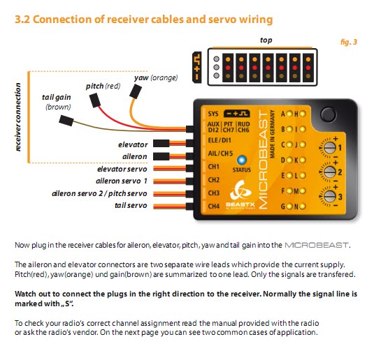 |
| Фрагмент инструкции |
Установка на модель.
Нижняя часть корпуса устройства выполнена из металла, от чего дополнительные металлические пластинки при установке не требуются. Устройство допускает установку как горизонтально, на нижнюю поверхность блока, так и вертикально, на ребро. В обоих случаях необходимо, чтобы разъемы были направлены либо к носу, либо к хвосту вертолета, но не вбок или вверх/вниз. Благодаря возможности работать на ребре, крепить блок можно на боку модели. В комплекте идет квадратная демпфирующая подушка для крепления. Подушка шире и короче чем блок, но в инструкции отдельно оговаривается, что подрезать подушку не надо, она обеспечивает оптимальное демпфирование именно в таком виде.
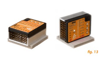 |
| Картинка из инструкции. Пример установки блока горизонтально и вертикально. |
При установке блока на модель я старался проложить провода так, чтобы они не тянули блок в сторону или вниз, т.е. не сжимали и не перекашивали подушку, на которой блок наклеен. С учетом того, что в комплекте идут достаточно жесткие провода, сделать это на небольшой модели достаточно проблематично. В итоге провода пришлось пустить дугой по балке. Для большей безопасности я обернул и крепко стянул провода у блока липучкой, чтобы они не имели возможности выскочить из разъемов.
 |
| Система установлена на модель. |
Настройка аппаратуры.
Для работы MICROBEAST требуется выбрать тип автомата перекоса H1 (механический), когда каждой функции перекоса соответствует отдельный сервопривод. Использование сабтриммеров, лимитов и триммеров на каналах автомата перекоса в передатчике запрещены. Настройка этих параметров осуществляется в MICROBEAST. В дальнейшем для тонкой настройки поведения модели можно использовать двойные расходы и экспоненту в передатчике.
Базовая настройка.
Базовая настройка состоит из 14 шагов и выполняется с помощью передатчика и кнопки на корпусе блока. Кнопкой сменяются шаги настройки, а стиками на пульте выбираются или настраиваются параметры на каждом шаге.
Шаги настройки.
- Режим работы – бесфлайбарная система или только хвостовой гироскоп.
- Способ установки – горизонтально или на боку.
- Частота сигнала сервоприводов автомата перекоса. Поддерживаются частоты: 50Гц, 65Гц, 120Гц, 200Гц. В конце инструкции есть таблица с рекомендуемыми параметрами для наиболее распространенных сервоприводов. Для Align DS510 инструкция рекомендуют 200Гц.
- Ширина импульса хвостового сервопривода. Опять в инструкции есть подсказка для наиболее распространенных сервоприводов. Поддерживаются импульсы шириной: 760мкс, 960мкс, 1520мкс.
- Частота сигнала хвостового сервопривода. Обычно хвостовые гироскопы работают на частоте 333Гц. Поддерживаются частоты 50Гц, 165Гц, 270Гц, 333Гц.
- Лимиты хвостового сервопривода. Лимиты раздельные. Настройка аналогична обычному гироскопу, требуется выполнить настройку лимитов хода слайдера шага хвостового ротора влево и вправо. Система выполняет проверку расходов сервопривода, и если лимиты будут очень маленькими, настройка не сохранится.
- Реверс хвоста. Так же стандартная функция для любого гироскопа.
- Настройка сабтриммеров сервоприводов автомата перекоса. Позволяет подровнять качалки сервоприводов в среднем положении стика шага. На этом шаге тягами необходимо подровнять тарелку в горизонт и выставить на лопастях нулевой шаг.
- Выбор схемы автомата перекоса: механический, 90 градусов, 120 градусов, 140 градусов
- Проверка геометрии автомата перекоса. На этом шаге требуется установить на лопастях циклический шаг в 6 градусов. При этом система фиксирует выбранное положение тарелки, чтобы не надо было удерживать стик на аппаратуре. Для угла 6 градусов система проверяет расходы на сервоприводах и, если геометрия удовлетворительная, то на корпусе устройства загорается синий индикатор. Если геометрия плохая, т.е. расход на сервоприводах меньше ожидаемого системой, то индикатор светится оранжевым или красным, в зависимости от того, насколько все плохо. Инструкция в этом случае рекомендует уменьшить длину качалок сервоприводов, или уменьшить вылет шариков на внутренней обойме тарелки перекоса, к которым подходят тяги от цапф.
- Максимальные углы общего шага. Выставляются отдельно для положительных и отрицательных шагов. После окончания настройки углы общего шага регулируются, как и положено, кривой шага в передатчике.
- Лимиты автомата перекоса. На этом шаге определяем, какой максимальный циклический шаг будет доступен системе. Необходимо убедиться, что механика перекоса не упирается при полных отклонениях по общему и циклическому шагу. По необходимости требуется с помощью стика на аппаратуре отрегулировать лимиты отклонения тарелки по циклическому шагу.
- Реверс датчиков перекоса. Наклоняя модель вперед-назад и влево-вправо необходимо убедиться, что тарелка перекоса отклоняется в сторону, противоположную наклону модели.
- Реверс оптимизации пируэта. Это одна из самых эффектных настроек. На этом шаге система наклоняет тарелку перекоса в одну сторону. Вращая вертолет в руках вокруг вертикальной оси нужно убедиться, что тарелка сохраняет направление наклона независимо от того, куда вы поворачиваете вертолет.
Тонкая настройка.
На корпусе есть три потенциометра, которые отвечают за регулировку следующих параметров:
- Swashplate gain — чувствительность датчиков перекоса. Аналогично чувствительности гироскопа, если на маневрах и остановках появляется раскачка, необходимо уменьшить этот параметр.
- Swashplate direct gain — прямой ввод на автомат перекоса. Определяет, насколько живо модель будет реагировать на управление. Увеличивая этот параметр можно получить очень верткий и менее стабильный вертолет, который будет моментально отзываться на движение стиков.
- Tail dynamic — динамика хвоста позволяет сделать остановки и старты пируэта более жесткими или более мягкими.
Чувствительность хвостового гироскопа регулируется с передатчика как обычно. При изменении чувствительность 14 индикаторов имитируют шкалу, отображая примерный процент чувствительность.
Кроме механических потенциометров есть следующие тонкие настройки модуля:
- Триммирование тарелки перекоса позволяет убрать незначительный дрейф модели на висении. Функция аналогична триммерам на передатчике, но из-за особенностей работы нужно пользоваться триммером в системе.
- Режим работы: Нормальный (Normal), спортивный (Sport), профи (Pro), экстремальный (Extreme) и настройка с пульта. Выбор режима работы по настройкам аналогичен двойным расходам и экспоненте в передатчике.
- Коррекция элеватора при работе шагом – стабильность удержания курса по элеватору на высокой скорости и при резкой работе шагом. Более высокое значение делает вертолет ленивым по элеватору, слишком низкое вызывает раскачку по элеватору.
- Чувствительность удержания хвоста. Низкое значение сделает скорость пируэта неравномерной, высокое вызовет постоянное рысканье хвоста даже на простом висении.
Конфигурация тестового вертолета:
- Align Trex 500ESP (привод ХР: вал)
- Мотор: Scorpion 3026-1210@14T
- Регулятор: Castle Creations ICE 75
- Аккумуляторы: 8S: 2×2150мАч, Rhino 4S, 30C
- Рулевая машинка Align DS520
- Обороты ротора 2610 об/мин.
- Лопасти Maniac 427
- Общий шаг: +-12 градусов
- Версия прошивки MICROBEAST: 1.0.11 – 2.0
 |
| Для тестирования использовался бесфлайбарный ротор Align. |
Полет.
Сразу после включения питания система начинает инициализацю. Индикаторы на корпусе отдельно отображают инициализацию датчиков и приемника. После окончания процедуры система коротко двигает тарелку перекоса вверх-вниз.
Первый полет выполнялся с пресетом Pro, на котором в итоге и остановился. Все потенциометры находились в среднем положении. Сначала подстроил чувствительность гироскопа, остановился на 47%. По элеронам и элеватору вертолет реагировал несколько вяло, поэтому увеличил чувствительность прямого ввода на тарелку, после чего вертолет стал реагировать на управление более агрессивно. Подкрутил этот потенциометр еще немного в плюс и вертолет стал «выскальзывать» из рук, как будто эффект от работы системы стабилизации уменьшилась. Убавил на прежнее место: +1 деление от центрального положения, так и оставил. Затем настала очередь еще раз повозиться с хвостом. Старты и остановки пируэта были очень мягкие. На это дело есть потенциометр номер 3. Увеличив динамику хвоста примерно на 2 деления, получил более агрессивные старты и остановки пируэта. В передатчике на руль добавил экспоненту +10% для смягчения работы стика в околонулевой зоне. Стало более комфортно управлять хвостом.
Итак, можно переходить к полетам. Вертолет зависает в воздухе без каких-либо дополнительных усилий. Висит! И висит ровно! Никаких триммеров для тарелки не потребовалось. Полеты по прямой, бочки и петли не выявили никаких замечаний. Все фигуры получаются ровно, как на идеально настроенном флайбарном вертолете. Флипы не выявили никаких проблем с фазингом. Даже петля с кувырками не потребовала коррекции. На четырехточечном тик-таке создалось впечатление, что вертолет делает фигуру немного не так, как на флайбаре. Дело оказалось в более быстрых переворотах по циклическому шагу. Немного приноровившись к быстрой реакции на циклический шаг, смог выполнить фигуру ровнее. Позже немного уменьшил скорость, убавив на 5% двойные расходы в передатчике. Стоит ли еще раз говорить, что при отсутствии флайбара высвобождается около 15% дополнительной мощности?  И эта мощность отлично чувствуется на нагруженных фигурах.
Воронки система пишет, как по циркулю, без необходимости подравнивать модель по элеватору. Змейки тоже получаются легко. Выход с тейлслайда хороший, с резкой отработкой по шагу. Подхват по шагам происходит гораздо быстрее, чем ожидаешь от электронной системы! Флипы в движении тоже получались без рывков по шагам.
Проверяю пирокомпенсацию. На месте вертолет вращается без заметного сваливания, только обычный дрейф. При этом сохраняется нормальная возможность двигать вертолет. Вести вертолет в пируэте получалось даже немного легче, чем с флайбаром, поскольку с электронной системой модель лучше держит горизонт.
Чуть позже вернулся к настройке хвоста. На пару процентов убавил общую чувствительность. Остановки пируэтов стали идеально ровные с обеих сторон, до этого был небольшой отбой остановки пируэта. Несмотря на убавленную чувствительность, хвост держит железно, даже на жестком выходе с тейлслайда.
Затем стал пристально вглядываться в поведение хвоста на пируэтах. Если крутить вертолет равномерно и при этом играть шагом вверх вниз, то скорость пируэта сохраняется. Если во время пируэта увеличивать и убавлять скорость вращения, то набирается скорость равномерно, если же снижать скорость пируэта, то она сбрасывается не плавно, а рывком. Рывок ярко выражен и хорошо заметен. По идее у
MICROBEAST нет другого выбора. Если сказали снижать скорость, то надо это делать быстро. В остальном никаких проблем с хвостом не заметил. Попробовал изменять чувствительность удержания хвоста. Увеличил значение со среднего на высокое и запинка стала более жесткая. Вернул обратно в среднее значение. К слову Spartan DS760 на снижение скорости пируэта имеет небольшую ступеньку, но она выглядит более мягкой, не такая заметная как на MICROBEAST.
Плюсы и минусы.
Плюсы:
- Цена;
- Стабильность и однозначность поведения модели даже на сложных фигурах;
- Работа оптимизации пируэта;
- Моментальный отклик по шагу;
- Простота настройки;
- Отличный хвостовой гироскоп.
Минусы:
- USB интерфейс приобретается отдельно;
- На данный момент нет возможности настройки через компьютер;
- На данный момент нет возможности использовать приемники-сателлиты;
- Нет переключения банков настроек. Переключение может пригодиться для выполнения трюков во время авторотации;
- В комплекте слишком толстые и жесткие соединительные провода. Может вызвать проблему при размещении блока на небольших моделях. Возможно, для небольших моделей потребуется самостоятельная замена проводов на более мягкие;
- Для некоторых маневров вращения недостаточно равномерные;
- Отсутствует настройка мертвой зоны в центре стика руля.
Выводы.
Система явно удалась! По полету масса положительных впечатлений, поведение модели однозначное, напоминает работу хорошо настроенного вертолета с флайбаром. Система не разочарует тех, кто ищет от вертолета резкой, моментальной реакции. При этом система на удивление проста в настройке, а благодаря возможности установки на ребро она сможет прижиться даже на маленьких моделях, где нет достаточно места на горизонтальных поверхностях. Как и у любой системы, у этой есть недостатки, а насколько они критичны, каждый определит для себя сам.
Ссылки:
Сайт BeastX
Ссылка на английскую инструкцию