-
Contents
-
Table of Contents
-
Troubleshooting
-
Bookmarks
Quick Links
Configuration and Use Manual
MMI-20019048, Rev AB
March 2018
®
Micro Motion
Model 2700 Transmitters with
Intrinsically Safe Outputs
Configuration and Use Manual
Related Manuals for Emerson Micro Motion 2700
Summary of Contents for Emerson Micro Motion 2700
-
Page 1
Configuration and Use Manual MMI-20019048, Rev AB March 2018 ® Micro Motion Model 2700 Transmitters with Intrinsically Safe Outputs Configuration and Use Manual… -
Page 2
Micro Motion employees. Micro Motion will not accept your returned equipment if you fail to follow Micro Motion procedures. Return procedures and forms are available on our web support site at www.emerson.com, or by phoning the Micro Motion Customer Service department. -
Page 3: Table Of Contents
Contents Contents Part I Getting started Chapter 1 Before you begin ………………….3 About this manual ……………………. 3 Transmitter model code …………………… 3 Communications tools and protocols ……………….. 4 Additional documentation and resources ………………4 Chapter 2 Quick start ……………………5 Power up the transmitter …………………..5 Check meter status ……………………5 2.2.1…
-
Page 4
Contents 4.5.2 Configure two-phase flow parameters …………….43 4.5.3 Configure Density Damping ………………45 4.5.4 Configure Density Cutoff ………………..46 Configure temperature measurement ………………47 4.6.1 Configure Temperature Measurement Unit …………..47 4.6.2 Configure Temperature Damping …………….48 4.6.3 Effect of Temperature Damping on process measurement ……….. 48 4.6.4 Configure Temperature Input ……………… -
Page 5
Contents Configure the transmitter channels ………………… 87 Configure the mA Output ………………….88 6.2.1 Configure mA Output Process Variable ……………. 88 6.2.2 Configure Lower Range Value (LRV) and Upper Range Value (URV) …….91 6.2.3 Configure AO Cutoff …………………93 6.2.4 Configure Added Damping ……………….94 6.2.5 Configure mA Output Fault Action and mA Output Fault Level …….. -
Page 6
Contents Use Smart Meter Verification (SMV) ………………140 9.2.1 SMV requirements …………………. 140 9.2.2 SMV test preparation ………………..140 9.2.3 Run SMV ……………………141 9.2.4 View test data ………………….145 9.2.5 Schedule automatic execution of the SMV test …………149 Use PVR, TBR, and TMR ………………….152 9.3.1 PVR, TBR, and TMR applications ……………… -
Page 7
Contents 10.22 Check Frequency Output Fault Action ………………198 10.23 Check Flow Direction …………………… 199 10.24 Check the cutoffs ……………………199 10.25 Check for two-phase flow (slug flow) ………………199 10.26 Check the drive gain ……………………200 10.26.1 Collect drive gain data ………………..201 10.27 Check the pickoff voltage …………………. -
Page 8
Contents Micro Motion Model 2700 Transmitters with Intrinsically Safe Outputs… -
Page 9: Part I Getting Started
Getting started Part I Getting started Chapters covered in this part: • Before you begin • Quick start Configuration and Use Manual…
-
Page 10
Getting started Micro Motion Model 2700 Transmitters with Intrinsically Safe Outputs… -
Page 11: Before You Begin
Before you begin Before you begin Topics covered in this chapter: • About this manual • Transmitter model code • Communications tools and protocols • Additional documentation and resources About this manual This manual helps you configure, commission, use, maintain, and troubleshoot Micro Motion Model 2700 transmitters with intrinsically safe outputs.
-
Page 12: Communications Tools And Protocols
Smart Wireless THUM Adapter. Use of AMS or the Smart Wireless THUM Adapter is not discussed in this manual. For more information on the Smart Wireless THUM Adapter, refer to the documentation available at www.emerson.com. Additional documentation and resources Topic…
-
Page 13: Chapter 2 Quick Start
Quick start Quick start Topics covered in this chapter: • Power up the transmitter • Check meter status • Make a startup connection to the transmitter • Verify mass flow measurement • Verify the zero Power up the transmitter The transmitter must be powered up for all configuration and commissioning tasks, or for process measurement.
-
Page 14: Transmitter Status Reported By Led
Quick start Wait approximately 10 seconds for the power-up sequence to complete. Immediately after power-up, the transmitter runs through diagnostic routines and checks for error conditions. During the power-up sequence, Alert A009 is active. This alert should clear automatically when the power-up sequence is complete. Check the status LED on the transmitter.
-
Page 15: Make A Startup Connection To The Transmitter
Quick start Make a startup connection to the transmitter For all configuration tools except the display, you must have an active connection to the transmitter to configure the transmitter. Identify the connection type to use, and follow the instructions for that connection type in the appropriate appendix.
-
Page 16: Terminology Used With Zero Verification And Zero Calibration
Quick start • The zero is required by site procedures. • The stored zero value fails the zero verification procedure. Procedure Allow the flowmeter to warm up for at least 20 minutes after applying power. Run the process fluid through the sensor until the sensor temperature reaches the normal process operating temperature.
-
Page 17
Quick start Term Definition Prior Zero The zero value stored in the transmitter at the time a field zero calibration is begun. May be the factory zero or a previous field zero. Manual Zero The zero value stored in the transmitter, typically obtained from a zero calibration procedure. -
Page 18
Quick start Micro Motion Model 2700 Transmitters with Intrinsically Safe Outputs… -
Page 19: Part Ii Configuration And Commissioning
Configuration and commissioning Part II Configuration and commissioning Chapters covered in this part: • Introduction to configuration and commissioning • Configure process measurement • Configure device options and preferences • Integrate the meter with the control system Complete the configuration •…
-
Page 20
Configuration and commissioning Micro Motion Model 2700 Transmitters with Intrinsically Safe Outputs… -
Page 21: Introduction To Configuration And Commissioning
Introduction to configuration and commissioning Introduction to configuration and commissioning Topics covered in this chapter: • Configuration flowchart • Default values and ranges • Enable access to the off-line menu of the display • Disable write-protection on the transmitter configuration •…
-
Page 22
Introduction to configuration and commissioning Figure 3-1: Configuration flowchart Configure device options and Test and move to production Configure process measurement preferences Configure mass flow Test or tune transmitter Configure display measurement using sensor simulation parameters Configure volume flow meaurement Configure fault handling Back up transmitter parameters… -
Page 23: Default Values And Ranges
Introduction to configuration and commissioning Default values and ranges Section D.1 to view the default values and ranges for the most commonly used parameters. Enable access to the off-line menu of the display Display OFF-LINE MAINT > OFF-LINE CONFG > DISPLAY ProLink III Device Tools >…
-
Page 24: Set The Hart Lock
Introduction to configuration and commissioning Set the HART lock If you plan to use a HART connection to configure the device, you can lock out all other HART masters. If you do this, other HART masters will be able to read data from the device but will not be able to write data to the device.
-
Page 25
Introduction to configuration and commissioning Important You cannot restore factory configurations with a 700 core. Restoring the factory configuration is not a common action. You may want to contact customer support to see if there is a preferred method to resolve any issues. Configuration and Use Manual… -
Page 26
Introduction to configuration and commissioning Micro Motion Model 2700 Transmitters with Intrinsically Safe Outputs… -
Page 27: Configure Process Measurement
Configure process measurement Configure process measurement Topics covered in this chapter: • Configure mass flow measurement • Configure volume flow measurement for liquid applications • Configure GSV flow measurement • Configure Flow Direction • Configure density measurement • Configure temperature measurement •…
-
Page 28
Configure process measurement If the measurement unit you want to use is not available, you can define a special measurement unit. Options for Mass Flow Measurement Unit The transmitter provides a standard set of measurement units for Mass Flow Measurement Unit, plus one user-defined special measurement unit. -
Page 29
Configure process measurement Define a special measurement unit for mass flow Display Not available ProLink III Device Tools > Configuration > Process Measurement > Flow > Special Units Field Communicator Configure > Manual Setup > Measurements > Special Units > Mass Special Units Overview A special measurement unit is a user-defined unit of measure that allows you to report process data, totalizer data, and inventory data in a unit that is not available in the… -
Page 30: Configure Flow Damping
Configure process measurement a. 1 lb/sec = 16 oz/sec b. Mass Flow Conversion Factor = 1 ÷ 16 = 0.0625 Set Mass Flow Conversion Factor to 0.0625. Set Mass Flow Label to oz/sec. Set Mass Total Label to oz. 4.1.2 Configure Flow Damping Display Not available…
-
Page 31: Configure Mass Flow Cutoff
Configure process measurement Effect of flow damping on volume measurement Flow damping affects volume measurement for liquid volume data. Flow damping also affects volume measurement for gas standard volume data. The transmitter calculates volume data from the damped mass flow data. Interaction between Flow Damping and mA Output Damping In some circumstances, both Flow Damping and mA Output Damping are applied to the…
-
Page 32: Configure Volume Flow Measurement For Liquid Applications
Configure process measurement Interaction between Mass Flow Cutoff and mA Output Cutoff Mass Flow Cutoff defines the lowest mass flow value that the transmitter will report as measured. mA Output Cutoff defines the lowest flow rate that will be reported via the mA output.
-
Page 33: Configure Volume Flow Type For Liquid Applications
Configure process measurement Restriction You cannot implement both liquid volume flow and gas standard volume flow at the same time. Choose one or the other. Note If you need to switch from gas standard volume to liquid volume, polling for base density will automatically be disabled.
-
Page 34
Configure process measurement Overview Volume Flow Measurement Unit specifies the unit of measurement that will be displayed for the volume flow rate. The unit used for the volume total and volume inventory is based on this unit. Prerequisites Before you configure Volume Flow Measurement Unit, be sure that Volume Flow Type is set to Liquid. -
Page 35
Configure process measurement Label Unit description Display ProLink III Field Communicator l/hr Liters per hour MILL/D mil l/day ML/d Million liters per day UKGPS Imp gal/sec Impgal/s Imperial gallons per second UKGPM Imp gal/min Impgal/min Imperial gallons per minute Imperial gallons per hour UKGPH Imp gal/hr Impgal/h… -
Page 36: Configure Volume Flow Cutoff
Configure process measurement Base Volume Unit is the existing volume unit that the special unit will be based on. Specify Base Time Unit. Base Time Unit is the existing time unit that the special unit will be based on. Calculate Volume Flow Conversion Factor as follows: a.
-
Page 37
Configure process measurement The default value for Volume Flow Cutoff is 0.0 l/sec (liters per second). The lower limit is Interaction between Volume Flow Cutoff and mAO Cutoff Volume Flow Cutoff defines the lowest liquid volume flow value that the transmitter will report as measured. -
Page 38: Configure Gsv Flow Measurement
Configure process measurement Configure GSV flow measurement The gas standard volume (GSV) flow measurement parameters control how volume flow is measured and reported in a gas application. Restriction You cannot implement both liquid volume flow and gas standard volume flow at the same time. Choose one or the other.
-
Page 39
Configure process measurement Overview The Standard Density of Gas value is the gas density at standard reference conditions. Use it to convert the measured mass flow data to volume flow at reference conditions. Prerequisites Ensure that Density Measurement Unit is set to the measurement unit you want to use for Standard Density of Gas. -
Page 40: Configure Gas Standard Volume Flow Unit
Configure process measurement Set Polling Control n as one of the following options: The n is the value you selected in the Polling Slot field. If there is another master, and if that master is primary, then set this field to secondary.
-
Page 41
Configure process measurement For polling, the first transmitter (master) requests density from a second transmitter (slave) via HART communications. Special units for GSV are allowed on the master side, but the device being polled (slave) cannot have special units set for density, otherwise the master will reject the base density and report an A115: No External Input or Polled Data Alert. -
Page 42
Configure process measurement Label Unit description Display ProLink III Field Communicator SLPD SLPD SLPD Standard liters per day SPECL special Special Special measurement unit Define a special measurement unit for gas standard volume flow Display Not available ProLink III Device Tools > Configuration > Process Measurement > Flow > Special Units Field Communicator Configure >… -
Page 43: Configure Gas Standard Volume Flow Cutoff
Configure process measurement The special measurement unit is stored in the transmitter. You can configure the transmitter to use the special measurement unit at any time. Example: Defining a special measurement unit for gas standard volume flow You want to measure gas standard volume flow in thousands of standard cubic feet per minute.
-
Page 44: Configure Flow Direction
Configure process measurement Gas Standard Volume Flow Cutoff affects both the gas standard volume flow values reported via outputs and the gas standard volume flow values used in other transmitter behavior (e.g., events defined on gas standard volume flow). mA Output Cutoff affects only flow values reported via the mA Output. Example: Cutoff interaction with mA Output Cutoff lower than Gas Standard Volume Flow Cutoff Configuration:…
-
Page 45: Options For Flow Direction
Configure process measurement Overview Flow Direction controls how forward flow and reverse flow affect flow measurement and reporting. Flow Direction is defined with respect to the flow arrow on the sensor: • Forward flow (positive flow) moves in the direction of the flow arrow on the sensor. •…
-
Page 46
Configure process measurement Effect of Flow Direction on mA Outputs Flow Direction affects how the transmitter reports flow values via the mA Outputs. The mA Outputs are affected by Flow Direction only if mA Output Process Variable is set to a flow variable. -
Page 47
Configure process measurement Figure 4-2: Effect of Flow Direction on the mA Output: Lower Range Value < 0 Flow Direction = Forward Flow Direction = Reverse, Negate Forward Flow Direction = Absolute Value, Bidirectional, Negate Bidirectional Reverse flow Forward flow Reverse flow Forward flow Reverse flow… -
Page 48
Configure process measurement • Under conditions of forward flow, for flow rates between 0 and +100 g/sec, the mA Output varies between 12 mA and 20 mA in proportion to (the absolute value of) the flow rate. • Under conditions of forward flow, if (the absolute value of) the flow rate equals or exceeds 100 g/sec, the mA Output is proportional to the flow rate up to 20.5 mA, and will be level at 20.5 mA at higher flow rates. -
Page 49
Configure process measurement Table 4-1: Effect of the flow direction parameter and actual flow direction on Frequency Outputs (continued) Actual flow direction Flow Direction setting Forward Zero flow Reverse Negate Bidirectional Hz > 0 0 Hz Hz > 0 Effect of flow direction on Discrete Outputs The flow direction parameter affects the Discrete Output behavior only if Discrete Output Source is set to Flow Direction. -
Page 50: Configure Density Measurement
Configure process measurement Table 4-3: Effect of the flow direction on flow values (continued) Actual flow direction Flow Direction setting Forward Zero flow Reverse Negate Bidirectional Negative Positive (1) Refer to the digital communications status bits for an indication of whether flow is positive or negative. Effect of flow direction on flow totals Flow direction affects how flow totals and inventories are calculated.
-
Page 51: Configure Two-Phase Flow Parameters
Configure process measurement Options for Density Measurement Unit The transmitter provides a standard set of measurement units for Density Measurement Unit. Different communications tools may use different labels. Label Unit description Display ProLink III Field Communicator Specific gravity Grams per cubic centimeter G/CM3 g/cm3 g/Cucm…
-
Page 52
Configure process measurement Gas entrainment can cause your process density to drop temporarily. To reduce the occurrence of two-phase flow alerts that are not significant to your process, set Two-Phase Flow Low Limit slightly below your expected lowest process density. You must enter Two-Phase Flow Low Limit in g/cm³, even if you configured another unit for density measurement. -
Page 53: Configure Density Damping
Configure process measurement If Two-Phase Flow Timeout is set to 0.0 seconds, the outputs that represent flow rate will report a flow rate of 0 as soon as two-phase flow is detected. 4.5.3 Configure Density Damping Display Not available ProLink III Device Tools >…
-
Page 54: Configure Density Cutoff
Configure process measurement The value you enter is automatically rounded off to the nearest valid value. The valid values for Density Damping depend on the setting of Update Rate. Update Rate setting Valid damping values Normal 0.0, 0.2, 0.4, 0.8, 1.6, 3.2, 6.4, 12.8, 25.6, 51.2 Special 0.0, 0.04, 0.08, 0.16, 0.32, 0.64, 1.28, 2.56, 5.12, 10.24, 20.48, 40.96…
-
Page 55: Configure Temperature Measurement
Configure process measurement Effect of Density Cutoff on volume measurement Density Cutoff affects liquid volume measurement. If the density value goes below Density Cutoff, the volume flow rate is reported as 0. Density Cutoff does not affect gas standard volume measurement. Gas standard volume values are always calculated from the value configured for Standard Gas Density or polled value if configured for polled base density.
-
Page 56: Configure Temperature Damping
Configure process measurement 4.6.2 Configure Temperature Damping Display Not available ProLink III Device Tools > Configuration > Temperature Field Communicator Configure > Manual Setup > Measurements > Temperature > Temp Damping Overview Temperature Damping controls the amount of damping that will be applied to the line temperature value, when the on-board temperature data is used (RTD).
-
Page 57: Configure Temperature Input
Configure process measurement Temperature compensation Temperature compensation adjusts process measurement to compensate for the effect of temperature on the sensor tubes. Petroleum measurement Temperature Damping affects petroleum measurement process variables only if the transmitter is configured to use temperature data from the sensor. If an external temperature value is used for petroleum measurement, Temperature Damping does not affect petroleum measurement process variables.
-
Page 58
Configure process measurement Prerequisites You will need API documentation for the API table that you select. Depending on your API table, you may need to know the thermal expansion coefficient (TEC) for your process fluid. You must know the reference temperature that you want to use. Procedure Choose Device Tools >… -
Page 59: Set Up Temperature Data For Petroleum Measurement Using Prolink Iii
Configure process measurement b. Verify that the referred density range of the selected table is adequate for your application. If you chose a C table, enter Thermal Expansion Coefficient (TEC) for your process fluid. Set Reference Temperature to the temperature to which density will be corrected in referred density calculations.
-
Page 60: Configure Petroleum Measurement Using The Field Communicator
Configure process measurement Option Description Setup Polling The meter polls an external de- a. Set Line Temperature Source to Poll for External Value. vice for temperature data. This b. Set Polling Slot to an available slot. data will be available in addi- c.
-
Page 61
Configure process measurement a. Open the Petroleum Measurement Source menu and select the API table number. Depending on your choice, you may be prompted to enter a reference temperature or a thermal expansion coefficient. b. Enter the API table letter. These two parameters uniquely specify the API table. -
Page 62: Api Tables Supported By The Petroleum Measurement Application
Configure process measurement 4.7.4 API tables supported by the petroleum measurement application The API tables listed here are supported by the petroleum measurement application. Table name Process fluid CTL source data Reference temperature Density unit Generalized crude and Observed density and 60 °F (non-configurable) Degrees API observed temperature…
-
Page 63: Set Up Concentration Measurement
Configure process measurement Restriction These tables are not appropriate for the following process fluids: propane and propane mixes, butane and butane mixes, butadiene and butadiene mixes, isopentane, LNG, LPG, NGL, ethylene, propylene, cyclohexane, aeromatics, asphalts, and road tars. Set up concentration measurement This section guides you through loading and setting up a concentration matrix used for measurement.
-
Page 64
Configure process measurement Important • All concentration matrices on your transmitter must use the same derived variable. If you are using one of the standard matrices from Micro Motion, set Derived Variable to Mass Concentration (Density). If you are using a custom matrix, see the reference information for your matrix. -
Page 65: Configure Concentration Measurement Using The Field Communicator
Configure process measurement Set Temperature Source to the method that the transmitter will use to obtain temperature data. Option Description The transmitter will poll an external temperature device, us- Poll for external value ing HART protocol over the primary mA output. The transmitter will use the temperature data from the sen- sor.
-
Page 66
Configure process measurement Choose Online > Configure > Manual Setup > Measurements > Temperature and set Temperature Unit to match the temperature unit used by your matrix. Choose Online > Configure > Manual Setup > Measurements and click Concentration Measurement. Enable or disable matrix switching, as desired. -
Page 67: Standard Matrices For The Concentration Measurement Application
Configure process measurement Option Setup A user-configured a. Choose Online > Configure > Manual Setup > Measurements . static temperature b. Click External Inputs. value c. Click Next. d. Enable External Temperature. e. Set Correction Temperature to the value to be used. Polling for tempera- a.
-
Page 68: Derived Variables And Calculated Process Variables
Configure process measurement If the standard matrices are not appropriate for your application, you can build a custom matrix or purchase a custom matrix from Micro Motion. Temperature Matrix name Description Density unit unit Derived variable Deg Balling °F Mass Concentration Matrix represents percent extract, by g/cm (Density)
-
Page 69
Configure process measurement Calculated process variables Density at reference Standard Derived tempera- volume Specific Concen- Net mass volume Variable Description ture flow rate gravity tration flow rate flow rate ✓ ✓ Density Mass/unit volume, cor- at Reference rected to a given refer- ence temperature ✓… -
Page 70: Configure Pressure Compensation
Not all sensors or applications require pressure compensation. The pressure effect for a specific sensor model can be found in the product data sheet located at www.emerson.com. If you are uncertain about implementing pressure compensation, contact customer service. Prerequisites You will need the flow factor, density factor, and calibration pressure values for your sensor.
-
Page 71
Configure process measurement The calibration pressure is the pressure at which your sensor was calibrated, and defines the pressure at which there is no pressure effect. If the data is unavailable, enter 20 PSI. Enter Flow Factor for your sensor. The flow factor is the percent change in the flow rate per PSI. -
Page 72: Configure Pressure Compensation Using The Field Communicator
Configure process measurement If you want to use digital communications, click Apply, then perform the necessary host programming and communications setup to write pressure data to the transmitter at appropriate intervals. Postrequisites If you are using an external pressure value, verify the setup by checking the External Pressure value displayed in the Inputs area of the main window.
-
Page 73: Options For Pressure Measurement Unit
Configure process measurement Option Setup Polling for pressure a. Ensure that the primary mA Output has been wired to support HART polling. b. Choose Online > Configure > Manual Setup > Measurements > External Pressure/Temperature > External Polling . c. Set Poll Control to Poll As Primary Host or Poll as Secondary Host. d.
-
Page 74
Configure process measurement Label Unit description Display ProLink III Field Communicator mBAR millibar mbar Millibar G/SCM g/cm2 g/Sqcm Grams per square centimeter KG/SCM kg/cm2 kg/Sqcm Kilograms per square centimeter Pascals pascals Kilopascals Kilopascals Megapascals Megapascals Torr @ 0 °C TORR Torr @ 0°C torr Atmospheres… -
Page 75: Configure Device Options And Preferences
Configure device options and preferences Configure device options and preferences Topics covered in this chapter: • Configure the transmitter display • Enable or disable operator actions from the display • Configure security for the display menus • Configure response time parameters •…
-
Page 76
Configure device options and preferences Overview You can control the process variables and diagnostic variables shown on the display, and the order in which they appear. The display can scroll through up to 15 variables in any order you choose. In addition, you can repeat variables or leave slots unassigned. Restrictions •… -
Page 77: Configure The Number Of Decimal Places (Precision) Shown On The Display
Configure device options and preferences Configure Display Variable 1 to track the primary mA Output Display OFF-LINE MAINT > OFF-LINE CONFG > DISPLY > VAR 1 ProLink III Device Tools > Configuration > Transmitter Display > Display Security Field Communicator Not available Overview You can configure Display Variable 1 to track mA Output Process Variable for the primary mA Output.
-
Page 78: Configure The Refresh Rate Of Data Shown On The Display
Configure device options and preferences For temperature and density process variables, the default value is 2 decimal places. For all other variables, the default value is 4 decimal places. The range is 0 to 5. The lower the precision, the greater the change must be for it to be reflected on the display. Do not set the precision too low or too high to be useful.
-
Page 79: Enable Or Disable The Display Backlight
Configure device options and preferences Option Description Disabled (de- The display shows Display Variable 1 and does not scroll automatically. The operator can move to the next display variable at any time using Scroll. fault) If you enabled Auto Scroll, set Scroll Rate as desired. The default value is 10 seconds.
-
Page 80: Enable Or Disable Operator Actions From The Display
Configure device options and preferences Enable or disable operator actions from the display You can configure the transmitter to let the operator perform specific actions using the display. • Enable or disable Totalizer Start/Stop from the display (Section 5.2.1) • Enable or disable Totalizer Reset from the display (Section 5.2.2) •…
-
Page 81: Enable Or Disable Totalizer Reset From The Display
Configure device options and preferences 5.2.2 Enable or disable Totalizer Reset from the display Display OFF-LINE MAINT > OFF-LINE CONFG > DISPLAY > TOTALS RESET ProLink III Device Tools > Configuration > Totalizer Control Methods Field Communicator Configure > Manual Setup > Display > Display Variable Menu Features > Totalizer Reset Overview You can configure whether or not the operator is able to reset totalizers from the display.
-
Page 82: Configure Security For The Display Menus
Configure device options and preferences Procedure Ensure that the alert menu is accessible from the display. To acknowledge alerts from the display, operators must have access to the alert menu. Enable or disable Acknowledge All Alerts as desired. Option Description Enabled (default) Operators can use a single display command to acknowledge all alerts at once.
-
Page 83: Configure Response Time Parameters
Configure device options and preferences Option Description Disabled Operator cannot access the alert menu. Note The transmitter status LED changes color to indicate that there are active alerts, but does not show specific alerts. To require a password for access to the maintenance section of the off-line menu and the Smart Meter Verification menu, enable or disable Off-Line Password.
-
Page 84: Configure Update Rate
Configure device options and preferences 5.4.1 Configure Update Rate Display Not available ProLink III Device Tools > Configuration > Process Measurement > Response > Update Rate Field Communicator Configure > Manual Setup > Measurements > Update Rate Overview Update Rate controls the rate at which process data is polled and process variables are calculated.
-
Page 85
Configure device options and preferences Effects of Update Rate = Special Incompatible features and functions Special mode is not compatible with the following features and functions: • Enhanced events. Use basic events instead. • All calibration procedures. • Zero verification. •… -
Page 86: Configure Response Time
Configure device options and preferences 5.4.2 Configure Response Time Display Not available ProLink III Device Tools > Configuration > Process Measurement > Response > Response Time Field Communicator Not available Overview Response Time is used to apply a different algorithm to the calculation of process variables from the raw process data.
-
Page 87: Configure Fault Timeout
Configure device options and preferences 5.5.1 Configure Fault Timeout Display Not available ProLink III Device Tools > Configuration > Fault Processing Field Communicator Configure > Alert Setup > Alert Severity > Fault Timeout Overview Fault Timeout controls the delay before fault actions are performed. Restriction Fault Timeout is applied only to the following alerts (listed by Status Alert Code): A003, A004, A005, A008, A016, A017, A033.
-
Page 88
Configure device options and preferences Use the default settings for Status Alert Severity unless you have a specific requirement to change them. Procedure Select a status alert. For the selected status alert, set Status Alert Severity as desired. Option Description Fault Actions when fault is detected: •… -
Page 89
Configure device options and preferences Table 5-2: Status alerts and Status Alert Severity (continued) Alert code Status message Default severity Notes Configurable? Fault A009 Transmitter Initializing/ Warming Up A010 Calibration Failure Fault A011 Zero Calibration Failed: Fault A012 Zero Calibration Failed: Fault High Fault… -
Page 90
Configure device options and preferences Table 5-2: Status alerts and Status Alert Severity (continued) Alert code Status message Default severity Notes Configurable? Meter Verification Aborted Fault A035 Applies only to transmitters with Smart Meter Verification. A100 mA Output 1 Saturated Informational Can be set to either Informational or Ignore, but cannot be set to Fault. -
Page 91: Configure Informational Parameters
Configure device options and preferences Table 5-2: Status alerts and Status Alert Severity (continued) Alert code Status message Default severity Notes Configurable? Informational A121 Extrapolation Alarm (Con- Applies only to transmitters with centration) the concentration measurement application. A131 Meter Verification in Pro- Informational Applies only to transmitters with gress: Outputs to Last…
-
Page 92: Configure Sensor Material
Configure device options and preferences 5.6.2 Configure Sensor Material Display Not available ProLink III Device Tools > Configuration > Informational Parameters > Sensor Field Communicator Configure > Manual Setup > Info Parameters > Sensor Information > Tube Wetted Mate- rial Overview Sensor Material lets you store the type of material used for your sensor’s wetted parts in transmitter memory.
-
Page 93: Configure Descriptor
Configure device options and preferences Overview Sensor Flange Type lets you store your sensor’s flange type in transmitter memory. This parameter is not used in processing and is not required. Procedure Obtain your sensor’s flange type from the documents shipped with your sensor, or from a code in the sensor model number.
-
Page 94: Configure Date
Configure device options and preferences 5.6.7 Configure Date Display Not available ProLink III Device Tools > Configuration > Informational Parameters > Transmitter Field Communicator Configure > Manual Setup > Info Parameters > Transmitter Info > Date Overview Date lets you store a static date (not updated by the transmitter) in transmitter memory. This parameter is not used in processing and is not required.
-
Page 95: Integrate The Meter With The Control System
Integrate the meter with the control system Integrate the meter with the control system Topics covered in this chapter: • Configure the transmitter channels • Configure the mA Output • Configure the Frequency Output • Configure the Discrete Output • Configure events •…
-
Page 96: Configure The Ma Output
Integrate the meter with the control system Postrequisites For each channel that you configured, perform or verify the corresponding input or output configuration. When the configuration of a channel is changed, the channel’s behavior will be controlled by the configuration that is stored for the selected input or output type, and the stored configuration may not be appropriate for your process.
-
Page 97
Integrate the meter with the control system • If you are using the HART variables, be aware that changing the configuration of mA Output Process Variable will change the configuration of the HART Primary Variable (PV). • If you are using the HART variables, be aware that changing the configuration of mA Output Process Variable will change the configuration of the HART Primary Variable (PV) and/or the HART Secondary Variable (SV). -
Page 98
Integrate the meter with the control system Table 6-2: Petroleum measurement mA Output process variables Label Process variable Display ProLink III Field Communicator Average corrected density AVE D Average Density TC Avg Dens Average temperature AVE T Average Temperature TC Avg Temp Temperature-corrected TCVOL Volume Flow Rate at Reference… -
Page 99: Configure Lower Range Value (Lrv) And Upper Range Value (Urv)
Integrate the meter with the control system Table 6-5: PVR mA Output process variables (continued) Label Process variable Display ProLink III Field Communicator Corrected water flow WTR60 Water Flow Rate At Reference Water Flow Rate at Reference Shrinkage factor corrected SFOIL SF Oil Flow Rate At Line Shrinkage Factor Oil Flow Rate…
-
Page 100
Integrate the meter with the control system Ensure that the measurement unit for the configured process variable has been set as desired. Procedure Set LRV and URV as desired. • LRVis the value of mA Output Process Variable represented by an output of 4 mA. The default value for LRV depends on the setting of mA Output Process Variable. -
Page 101: Configure Ao Cutoff
Integrate the meter with the control system Table 6-6: Default values for Lower Range Value (LRV) and Upper Range Value (URV) (continued) Process variable Concentration 100% Baume Specific gravity 6.2.3 Configure AO Cutoff Display Not available ProLink III Device Tools > Configuration > I/O > Outputs > mA Output Field Communicator •…
-
Page 102: Configure Added Damping
Integrate the meter with the control system Example: Cutoff interaction Configuration: • mA Output Process Variable = Mass Flow Rate • Frequency Output Process Variable = Mass Flow Rate • AO Cutoff = 10 g/sec • Mass Flow Cutoff = 15 g/sec Result: If the mass flow rate drops below 15 g/sec, all outputs representing mass flow will report zero flow.
-
Page 103
Integrate the meter with the control system Added Damping affects the reporting of mA Output Process Variable through the mA Output only. It does not affect the reporting of that process variable via any other method (e.g., a Frequency Output or digital communications), or the value of the process variable used in calculations. -
Page 104: Configure Ma Output Fault Action And Ma Output Fault Level
Integrate the meter with the control system • mA Output Damping = 2 seconds Result: A change in the mass flow rate will be reflected in the mA Output over a time period that is greater than 3 seconds. The exact time period is calculated by the transmitter according to internal algorithms which are not configurable.
-
Page 105: Configure The Frequency Output
Integrate the meter with the control system Options for mA Output Fault Action and mA Output Fault Level Option mA Output behavior mA Output Fault Level Upscale Goes to the configured fault level Default: 22.0 mA Range: 21.0 to 24.0 mA Downscale (default) Goes to the configured fault level Default: 3.2 mA…
-
Page 106
Integrate the meter with the control system Prerequisites If you plan to configure the output to report volume flow, ensure that you have set Volume Flow Type as desired: Liquid or Gas Standard Volume. If you plan to configure an output to report a concentration measurement process variable, ensure that the concentration measurement application is configured so that the desired variable is available. -
Page 107: Configure Frequency Output Polarity
Integrate the meter with the control system Table 6-10: Concentration measurement FO process variables (continued) Label Process variable Display ProLink III Field Communicator Standard volume flow rate STD V Volume Flow Rate at Reference ED Std Vol flo Temperature Table 6-11: Fuel consumption FO process variables Label Process variable…
-
Page 108: Configure Frequency Output Scaling Method
Integrate the meter with the control system Polarity option Reference voltage (OFF) Pulse voltage (ON) Active Low As determined by power supply, pull-up resistor, and load. See the installation manual for your transmitter. 6.3.3 Configure Frequency Output Scaling Method Display OFF-LINE MAINT >…
-
Page 109: Configure Frequency Output Fault Action And Frequency Output Fault Level
Integrate the meter with the control system If you specify Frequency=Flow, you must provide values for Rate Factor and Frequency Factor: Rate Factor The maximum flow rate that you want the Frequency Output to report. Frequency A value calculated as follows: Factor RateFactor FrequencyFactor =…
-
Page 110: Configure The Discrete Output
Integrate the meter with the control system The default value is 15000 Hz. The range is 10 to 15000 Hz. Options for Frequency Output Fault Action Table 6-12: Options for Frequency Output Fault Action Label Frequency Output behavior Upscale Goes to configured Upscale value: •…
-
Page 111: Configure Discrete Output Source
Integrate the meter with the control system 6.4.1 Configure Discrete Output Source Display OFF-LINE MAINT > OFF-LINE CONFG > IO > CH B > SET DO > DO SRC ProLink III Device Tools > Configuration > I/O > Outputs > Discrete Output Field Communicator Configure >…
-
Page 112
Integrate the meter with the control system Important If you assign Flow Switch to the Discrete Output, you should also configure Flow Switch Variable, Flow Switch Setpoint, and Hysteresis. Related information Configure an enhanced event Fault indication with the Discrete Output Configure Flow Switch parameters Display OFF-LINE MAINT >… -
Page 113: Configure Discrete Output Polarity
Integrate the meter with the control system 6.4.2 Configure Discrete Output Polarity Display OFF-LINE MAINT > OFF-LINE CONFG > IO > CH B > SET DO > DO POLAR ProLink III Device Tools > Configuration > I/O > Outputs > Discrete Output Field Communicator Configure >…
-
Page 114: Configure Events
Integrate the meter with the control system Note For some faults only: If Fault Timeout is set to a non-zero value, the transmitter will not implement the fault action until the timeout has elapsed. CAUTION! Do not use Discrete Output Fault Action as a fault indicator. If you do, you may not be able to distinguish a fault condition from a normal operating condition.
-
Page 115: Configure A Basic Event
Integrate the meter with the control system • Enhanced event model 6.5.1 Configure a basic event Display Not available ProLink III Device Tools > Configuration > Events > Basic Events Field Communicator Not available Overview A basic event is used to provide notification of process changes. A basic event occurs (is ON) if the real-time value of a user-specified process variable moves above (HI) or below (LO) a user-defined setpoint.
-
Page 116
Integrate the meter with the control system Overview An enhanced event is used to provide notification of process changes and, optionally, to perform specific transmitter actions if the event occurs. An enhanced event occurs (is ON) if the real-time value of a user-specified process variable moves above (HI) or below (LO) a user-defined setpoint, or in range (IN) or out of range (OUT) with respect to two user- defined setpoints. -
Page 117: Configure Digital Communications
Integrate the meter with the control system Options for Enhanced Event Action Label Action Display ProLink III Field Communicator Standard None (default) NONE None None Start sensor zero START ZERO Start Sensor Zero Perform auto zero Start/stop all totalizers START STOP Start/Stop All Totalization Start/stop totals Reset mass total…
-
Page 118: Configure Hart/Bell 202 Communications
Integrate the meter with the control system Note The service port responds automatically to a wide range of connection requests. It is not configurable. 6.6.1 Configure HART/Bell 202 communications HART/Bell 202 communications parameters support HART communications with the transmitter’s primary mA terminals over a HART/Bell 202 network. Configure basic HART parameters Basic HART parameters include the HART address, HART tags, and the operation of the primary mA Output.
-
Page 119
Integrate the meter with the control system Important If you use ProLink III to set HART Address to 0, the program automatically enables mA Output Action. If you use ProLink III to set HART Address to any other value, the program automatically disables mA Output Action. -
Page 120
Integrate the meter with the control system • If you set Burst Mode Output to send four user-specified variables, set the four process variables to be sent in each burst. • If you set Burst Mode Output to any other option, ensure that the HART variables are set as desired. -
Page 121
Integrate the meter with the control system Table 6-13: Standard HART process variables (continued) Process variable Primary Varia- Secondary Third Variable Fourth Varia- ble (PV) Variable (SV) (TV) ble (QV ) ✓ Mass Inventory ✓ Mass Total ✓ Meter Temperature (T-Series) ✓… -
Page 122
Integrate the meter with the control system Table 6-15: Concentration measurement HART process variables (continued) Process variable Primary Varia- Secondary Third Variable Fourth Varia- ble (PV) Variable (SV) (TV) ble (QV ) ✓ CM Standard Volume Total Table 6-16: Fuel consumption HART process variables Process variable Primary Varia- Secondary… -
Page 123
Integrate the meter with the control system Table 6-18: TMR-only HART process variables Process variable Primary Varia- Secondary Third Variable Fourth Varia- ble (PV) Variable (SV) (TV) ble (QV ) ✓ ✓ ✓ Remediated Mass Flow ✓ Remediated Mass Total ✓… -
Page 124: Configure Digital Communications Fault Action
Integrate the meter with the control system 6.6.2 Configure Digital Communications Fault Action Display Not available ProLink III Device Tools > Configuration > Fault Processing Field Communicator Configure > Alert Setup > I/O Fault Actions > Comm Fault Action Overview Digital Communications Fault Actionspecifies the values that will be reported via digital communications if the device encounters an internal fault condition.
-
Page 125
Integrate the meter with the control system Label ProLink III Field Communicator Description Not a Number Not-a-Number • Process variables are reported as IEEE NAN. • Drive gain is reported as measured. • Modbus scaled integers are reported as Max Int. -
Page 126
Integrate the meter with the control system Micro Motion Model 2700 Transmitters with Intrinsically Safe Outputs… -
Page 127: Complete The Configuration
Complete the configuration Complete the configuration Topics covered in this chapter: • Test or tune the system using sensor simulation • Back up transmitter configuration • Enable write-protection on the transmitter configuration Test or tune the system using sensor simulation Use sensor simulation to test the system’s response to a variety of process conditions, including boundary conditions, problem conditions, or alert conditions, or to tune the loop.
-
Page 128: Sensor Simulation
Complete the configuration Option Required values Sine Period Minimum Maximum For density, set Wave Form as desired and enter the required values. Option Required values Fixed Fixed Value Sawtooth Period Minimum Maximum Sine Period Minimum Maximum For temperature, set Wave Form as desired and enter the required values. Option Required values Fixed…
-
Page 129: Back Up Transmitter Configuration
Complete the configuration • All mass flow rate, temperature, and density values displayed or reported via outputs or digital communications • The mass total and mass inventory values • All volume calculations and data, including reported values, volume totals, and volume inventories •…
-
Page 130
Complete the configuration Overview If the transmitter is write-protected, the configuration is locked and nobody can change it until it is unlocked. This prevents accidental or unauthorized changes to the transmitter configuration parameters. Micro Motion Model 2700 Transmitters with Intrinsically Safe Outputs… -
Page 131: Part Iii Operations, Maintenance, And Troubleshooting
Operations, maintenance, and troubleshooting Part III Operations, maintenance, and troubleshooting Chapters covered in this part: • Transmitter operation • Measurement support • Troubleshooting Configuration and Use Manual…
-
Page 132
Operations, maintenance, and troubleshooting Micro Motion Model 2700 Transmitters with Intrinsically Safe Outputs… -
Page 133: Chapter 8 Transmitter Operation
Transmitter operation Transmitter operation Topics covered in this chapter: • Record the process variables • View process variables • View transmitter status using the status LED • View and acknowledge status alerts • Read totalizer and inventory values • Start and stop totalizers and inventories •…
-
Page 134: View Process Variables
Transmitter operation View process variables Display Scroll to the desired process variable. If AutoScroll is enabled, you can wait until the process variable is displayed. See Section 8.2.1 for more information. ProLink III View the desired variable on the main screen under Process Variables. See Section 8.2.2 for more information.
-
Page 135: View Process Variables And Other Data Using Prolink Iii
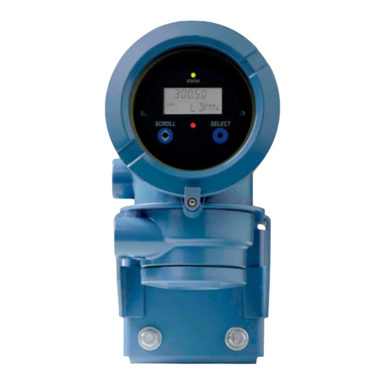
Transmitter operation Figure 8-1: Transmitter display features A. Status LED B. Display (LCD panel) C. Process variable D. Scroll optical switch E. Optical switch indicator: turns red when either Scroll or Select is activated F. Select optical switch G. Unit of measure for process variable H.
-
Page 136: View Transmitter Status Using The Status Led
Transmitter operation • To view a more complete set of process variables, plus the current state of the outputs, choose Service Tools > Variables. View transmitter status using the status LED The status LED shows the current alert condition of the transmitter. The status LED is located on the face of the transmitter.
-
Page 137: View And Acknowledge Status Alerts
Transmitter operation Table 8-1: Transmitter status reported by status LED (continued) LED state Description Recommendation Flashing red (if ena- One or more high-severity alerts are active A high-severity alert condition affects meas- bled) and have not been acknowledged. urement accuracy and output behavior. Re- solve the alert condition before continuing.
-
Page 138
Transmitter operation Figure 8-2: Using the display to view and acknowledge the status alerts Scroll and Select simultaneously for 4 seconds SEE ALARM Select Is ACK ALL enabled? ACK ALL Select Scroll EXIT Select Scroll Active/ unacknowledged alarms? Alarm code NO ALARM Scroll Select… -
Page 139: View And Acknowledge Alerts Using Prolink Iii
Transmitter operation Postrequisites • To clear the following alerts, you must correct the problem, acknowledge the alert, then power-cycle the transmitter: A001, A002, A010, A011, A012, A013, A018, A019, A022, A023, A024, A025, A028, A029, A031. • For all other alerts: If the alert is inactive when it is acknowledged, it will be removed from the list.
-
Page 140: View Alerts Using The Field Communicator
Transmitter operation If the alert is active when it is acknowledged, it will be removed from the list when the alert condition clears. Related information Alert data in transmitter memory 8.4.3 View alerts using the Field Communicator You can view a list containing all alerts that are active, or inactive but unacknowledged. •…
-
Page 141: Read Totalizer And Inventory Values
Transmitter operation Transmitter action if condition occurs Alert data structure Contents Clearing Recent Alerts 50 most recent alert postings or alert clearings Not cleared; maintained across transmitter power cycles Read totalizer and inventory values Display To read a totalizer or inventory value from the display, it must be configured as a display variable.
-
Page 142: Start And Stop Totalizers And Inventories Using The Display
Transmitter operation Important Totalizers and inventories are started or stopped as a group. When you start any totalizer, all other totalizers and all inventories are started simultaneously. When you stop any totalizer, all other totalizers and all inventories are stopped simultaneously. You cannot start or stop inventories directly.
-
Page 143: Reset Totalizers
Transmitter operation Reset totalizers Display Section 8.7.1. ProLink III Device Tools > Totalizer Control > Totalizer and Inventories > Reset Mass Total Device Tools > Totalizer Control > Totalizer and Inventories > Reset Volume Total Device Tools > Totalizer Control > Totalizer and Inventories > Reset Gas Total Device Tools >…
-
Page 144: Reset Inventories
Transmitter operation Reset and Yes? alternately flash beneath the current totalizer value. 5. Select again to confirm. 6. Scroll to EXIT. 7. Select. • To reset the volume totalizer: 1. Scroll until the volume totalizer value appears. 2. Select. Exit displays beneath the current totalizer value. 3.
-
Page 145
Transmitter operation Overview When you reset an inventory, the transmitter sets its value to 0. It does not matter whether the inventory is started or stopped. If the inventory is started, it continues to track process measurement. Mass and volume inventory totals cannot be set separately. They can only be reset together simultaneously. -
Page 146
Transmitter operation Micro Motion Model 2700 Transmitters with Intrinsically Safe Outputs… -
Page 147: Chapter 9 Measurement Support
Measurement support Measurement support Topics covered in this chapter: • Options for measurement support • Use Smart Meter Verification (SMV) • Use PVR, TBR, and TMR • Piecewise linearization (PWL) for calibrating gas meters • Use the fuel consumption application •…
-
Page 148: Use Smart Meter Verification (Smv)
Measurement support Use Smart Meter Verification (SMV) You can run an SMV test, view and interpret the results, and set up automatic execution. 9.2.1 SMV requirements To use SMV, the transmitter must be paired with an enhanced core processor. Table 9-1 for the minimum version of the transmitter, enhanced core processor, and communication tool needed to support SMV.
-
Page 149: Run Smv
Measurement support SMV has an output mode called Continuous Measurement that allows the transmitter to keep measuring while the test is in progress. If you choose to run the test in Last Measured Value or Fault modes instead, the transmitter outputs will be held constant for the two minute duration of the test.
-
Page 150
Measurement support Option Description Last Value During the test, all outputs will report the last measured value of their as- signed process variable. The test will run for approximately 140 seconds. While the test is in progress, dots traverse the display and test progress is shown. Postrequisites View the test results and take any appropriate actions. -
Page 151
Measurement support SMV flowchart: Running a test using the display Figure 9-2: Running an SMV test using the display RUN VERFY Select OUTPUTS EXIT Scroll Select CONTINUE MEASR FAULT LAST VALUE EXIT Scroll Scroll Scroll Select Select Select ARE YOU SURE/YES? Select . -
Page 152
Measurement support You may need to wait a few seconds while ProLink III synchronizes its database with the transmitter data. Enter any desired information on the Test Definition screen, and click Next. All information on this screen is optional. Choose the desired output behavior. Option Description Continue Measur-… -
Page 153: View Test Data
Measurement support Postrequisites View the test results and take any appropriate actions. 9.2.4 View test data You can view the results of the current test. You can also view results from previous tests. Important You can view previous test results and see detailed test reports only if SMV is licensed. The transmitter stores the following information about the previous twenty SMV tests: •…
-
Page 154
Measurement support Figure 9-3: SMV – Top-level menu Scroll and Select simultaneously for 4 seconds Scroll ENTER METER VERFY Select RUN VERFY RESULTS READ SCHEDULE VERFY EXIT Scroll Scroll Scroll Select Select Select Scroll Select b. Scroll to Results Read and press Select. The runcount of the most recent test is displayed. -
Page 155
Measurement support SMV flowchart: Viewing test results using the display Figure 9-4: Viewing SMV test results using the display RESULTS READ Select RUNCOUNT x Select Scroll Pass Result type Abort Fail xx HOURS xx HOURS xx HOURS Select Select Select PASS FAIL Abort Type… -
Page 156
Measurement support Procedure Choose Device Tools > Diagnostics > Meter Verification and click Previous Test Results. The chart shows test results for all tests stored in the ProLink III database. (Optional) Click Next to view and print a test report. (Optional) Click Export Data to CSV File to save the data to a file on your PC. -
Page 157: Schedule Automatic Execution Of The Smv Test
Measurement support Table 9-3: SMV abort codes Code Description Recommended actions User-initiated abort None required. Wait 15 seconds before starting an- other test. Frequency drift Ensure that temperature, flow, and density are sta- ble, and rerun the test. High drive gain Ensure that flow is stable, minimize entrained gas, and rerun the test.
-
Page 158
Measurement support Figure 9-5: SMV – Top-level menu Scroll and Select simultaneously for 4 seconds Scroll ENTER METER VERFY Select RUN VERFY RESULTS READ SCHEDULE VERFY EXIT Scroll Scroll Scroll Select Select Select Scroll Select Scroll to Schedule Verfy and press Select. To schedule a single test or the first test in recurring execution: a. -
Page 159
Measurement support SMV flowchart: Scheduling test execution using the display Figure 9-6: Scheduling SMV test execution using the display SCHEDULE VERFY Select Schedule set? SCHED IS OFF TURN OFF SCHED/YES? Scroll Scroll Select Schedule deleted HOURS LEFT Scroll Select xx HOURS Select SET NEXT SET RECUR… -
Page 160: Use Pvr, Tbr, And Tmr
Measurement support To schedule recurring execution, specify a value for Hours Between Recurring Runs. To disable scheduled execution: • To disable execution of a single scheduled test, set Hours Until Next Run to 0. • To disable recurring execution, set Hours Between Recurring Runs to 0. •…
-
Page 161: Pvr, Tbr, And Tmr Applications
Measurement support 9.3.1 PVR, TBR, and TMR applications PVR, TBR, and TMR are applications designed to provide more accurate process data in the presence of multiple phases. For example, if bubbles are present in the process fluid, or the process fluid is flashing, the volume measurements are often incorrect. Production Volume Reconciliation (PVR) •…
-
Page 162: Piecewise Linearization (Pwl) For Calibrating Gas Meters
PWL does not apply when measuring liquid flow. When better accuracy is required over the published gas measurement specifications, an Emerson-approved independent gas laboratory can calibrate gas up to 10 PWL adjustment points.
-
Page 163: Zero The Meter
Measurement support Standard process variables Standard and differential process variables Supply transmitter Return transmitter HART cable Engine Supply sensor Return sensor Storage tank Zero the meter Zeroing the meter establishes a baseline for process measurement by analyzing the sensor’s output when there is no flow through the sensor tubes. Prerequisites Verify the zero and prepare the meter using the procedures in Section…
-
Page 164: Validate The Meter
Measurement support Tool Path Field Communicator Service Tools > Maintenance > Zero Calibration > Perform Auto Zero If necessary, modify Zero Time. Zero Time controls the amount of time the transmitter takes to determine its zero-flow reference point. The default Zero Time is 20 seconds. For most applications, the default Zero Time is appropriate.
-
Page 165
Measurement support Important To adjust volume flow, you must set the meter factor for volume flow. Setting a meter factor for mass flow and a meter factor for density will not produce the desired result. The volume flow calculations are based on original mass flow and density values, before the corresponding meter factors have been applied. -
Page 166: Alternate Method For Calculating The Meter Factor For Volume Flow
Measurement support The new meter factor for mass flow is 0.9996. 9.7.1 Alternate method for calculating the meter factor for volume flow The alternate method for calculating the meter factor for volume flow is used to avoid the difficulties that may be associated with the standard method. This alternate method is based on the fact that volume is inversely proportional to density.
-
Page 167: Perform A D1 And D2 Density Calibration Using Prolink Iii
Measurement support Use meter validation and meter factors, rather than calibration, to prove the meter against a regulatory standard or to correct measurement error. Prerequisites • During density calibration, the sensor must be completely filled with the calibration fluid, and flow through the sensor must be at the lowest rate allowed by your application.
-
Page 168: Perform A D1 And D2 Density Calibration Using The Field Communicator
Measurement support Postrequisites If you disabled LD Optimization before the calibration procedure, re-enable it. 9.8.2 Perform a D1 and D2 density calibration using the Field Communicator Read the Prerequistes on page 159 if you have not already done so. See the following figure. Micro Motion Model 2700 Transmitters with Intrinsically Safe Outputs…
-
Page 169: Perform A D3 And D4 Density Calibration (T-Series Sensors Only)
Measurement support Postrequisites If you disabled LD Optimization before the calibration procedure, re-enable it. Perform a D3 and D4 density calibration (T- Series sensors only) For T-Series sensors, the optional D3 and D4 calibration could improve the accuracy of the density measurement if the density of your process fluid is less than 0.8 g/cm or greater than 1.2 g/cm…
-
Page 170: Perform A D3 Or D3 And D4 Density Calibration Using Prolink Iii
Measurement support • Perform both the D3 and D4 calibrations if you have two calibrated fluids (other than air and water). The calibrations must be performed without interruption, in the order shown. Make sure that you are prepared to complete the process without interruption.
-
Page 171: Perform A D3 Or D3 And D4 Density Calibration Using The Field Communicator
Measurement support Figure 9-7: D3 or D3 and D4 density calibration using ProLink III Close shutoff valve downstream from sensor D3 Calibration D4 Calibration Fill sensor with D3 fluid Fill sensor with D4 fluid Device Tools > Device Tools > Calibration >…
-
Page 172: Perform Temperature Calibration
Measurement support Figure 9-8: D3 or D3 and D4 density calibration using the Field Communicator D3 Calibration D4 Calibration Close shutoff valve Fill sensor with D3 fluid Fill sensor with D4 fluid downstream from sensor On-Line Menu > Service Tools > Service Tools >…
-
Page 173: Perform Temperature Calibration Using The Display
Measurement support Prerequisites The temperature calibration is a two-part procedure: temperature offset calibration and temperature slope calibration. The two parts must be performed without interruption, in the order shown. Ensure that you are prepared to complete the process without interruption. You will need a low-temperature calibration fluid and a high-temperature calibration fluid.
-
Page 174
Measurement support Temperature Offset Calibration Temperature Slope Calibration Fill sensor with Fill sensor with low-temperature fluid high-temperature fluid Wait until sensor achieves Wait until sensor achieves thermal equilibrium thermal equilibrium Device Tools > Device Tools > Calibration > Calibration > Temperature Calibration >… -
Page 175: Perform Temperature Calibration Using The Field Communicator
Measurement support 9.10.3 Perform temperature calibration using the Field Communicator Temperature Offset calibration Temperature Slope calibration Fill sensor with low- Fill sensor with high- temperature fluid temperature fluid Wait until sensor achieves Wait until sensor achieves thermal equilibrium thermal equilibrium Service Tools >…
-
Page 176
Measurement support Micro Motion Model 2700 Transmitters with Intrinsically Safe Outputs… -
Page 177: Chapter 10 Troubleshooting
Troubleshooting Troubleshooting Topics covered in this chapter: • Status LED states • Status alerts, causes, and recommendations • Locate a device using the HART 7 Squawk feature • Flow measurement problems • Density measurement problems • Temperature measurement problems • Milliamp output problems •…
-
Page 178: Status Led States
Troubleshooting 10.1 Status LED states The status LED on the transmitter indicates whether or not alerts are active. If alerts are active, view the alert list to identify the alerts, then take appropriate action to correct the alert condition. Your transmitter has a status LED only if it has a display. If the transmitter has a display and LED Blinking is disabled, the status LED does not flash to indicate an unacknowledged alert.
-
Page 179
Troubleshooting Alert num- Alert title Possible cause Recommended actions A002 RAM Error (Core Pro- The core processor has experienced • Cycle power to the meter. cessor) a memory error. • Replace the core processor. • Contact customer support. A003 No Sensor Response The transmitter is not receiving one •… -
Page 180
Troubleshooting Alert num- Alert title Possible cause Recommended actions A008 Density Overrange The line density is greater than • If other alerts are present, resolve those 10 g/cm (10000 kg/m alert conditions first. If the current alert persists, continue with the recommen- ded actions. -
Page 181
Troubleshooting Alert num- Alert title Possible cause Recommended actions A011 Zero Calibration Many possible causes, such as too • Verify that there is no flow through the Failed: Low much flow, especially reverse flow, sensor, cycle power to the meter, then through the sensor during a calibra- retry the procedure. -
Page 182
Troubleshooting Alert num- Alert title Possible cause Recommended actions A017 Sensor Case Tem- The values computed for the resist- • Check your process conditions against perature (RTD) Fail- ance of the meter and case RTDs the values reported by the device. Tem- are outside limits. -
Page 183
Troubleshooting Alert num- Alert title Possible cause Recommended actions A020 Calibration Factors Some calibration factors have not • Verify all of the characterization or cali- Missing been entered or are incorrect. bration parameters. See the sensor tag or the calibration sheet for your meter. •… -
Page 184
Troubleshooting Alert num- Alert title Possible cause Recommended actions A026 Sensor/Transmitter The transmitter has lost communi- • Check the wiring between the sensor Communications cation with the core processor. and the transmitter. Failure There may be a problem with the •… -
Page 185
Troubleshooting Alert num- Alert title Possible cause Recommended actions A033 Insufficient Pickoff The signal from the sensor pick- • Check for air in the flow tubes, tubes Signal off(s) is insufficient. This suggests not filled, foreign material in the tubes, that the sensor tubes or vibrating coating in the tubes, or other process elements are not vibrating. -
Page 186
Troubleshooting Alert num- Alert title Possible cause Recommended actions A102 Drive Overrange The drive power (current/voltage) is • Check the drive gain and the pickoff at its maximum. voltage. • Check the wiring between the sensor and the transmitter. • Verify that internal wiring is secure and that there are no internal electrical problems. -
Page 187
Troubleshooting Alert num- Alert title Possible cause Recommended actions A108 Basic Event 1 On The process has triggered Basic • No action required. Event 1. • Review event configuration if you be- lieve the event was triggered errone- ously. A109 Basic Event 2 On The process has triggered Basic •… -
Page 188
Troubleshooting Alert num- Alert title Possible cause Recommended actions A117 Density Overrange The measured density is outside the • Check your process conditions against (Petroleum) range of the API table. the values reported by the device. • Verify the configuration of the petrole- um measurement application and rela- ted parameters. -
Page 189: Locate A Device Using The Hart 7 Squawk Feature
Troubleshooting 10.3 Locate a device using the HART 7 Squawk feature The Squawk feature causes the device to show a specific pattern on its display. You can use this to locate or identify a device. Restriction The Squawk feature is available only with HART 7 connections from the Field Communicator. It is not available with ProLink III.
-
Page 190
Troubleshooting Problem Possible causes Recommended actions Erratic non-zero flow • Leaking valve or seal • Verify that the sensor orientation is appro- rate at no-flow condi- • Two-phase flow priate for your application (refer to the tions • Plugged or coated sensor tube sensor installation manual). -
Page 191: Density Measurement Problems
Troubleshooting Problem Possible causes Recommended actions Inaccurate flow rate • Wiring problem • Check the wiring between the sensor and or batch total • Inappropriate measurement unit the transmitter. • Incorrect flow calibration factor • Verify that the measurement units are con- •…
-
Page 192: Temperature Measurement Problems
Troubleshooting Problem Possible causes Recommended actions Unusually high densi- • Plugged or coated sensor tube • Ensure that all of the calibration parame- ty reading • Incorrect density calibration factors ters have been entered correctly. See the • Incorrect temperature measurement sensor tag or the calibration sheet for your •…
-
Page 193: Milliamp Output Problems
Troubleshooting Problem Possible causes Recommended actions Temperature reading • Sensor temperature not yet equalized • If the error is within the temperature speci- slightly different from • Sensor leaking heat fication for the sensor, there is no prob- process temperature lem.
-
Page 194
Troubleshooting Table 10-2: Milliamp output problems and recommended actions (continued) Problem Possible causes Recommended actions Loop test failed • Output not powered • Verify that the output loop is powered ex- • Power supply problem ternally. • Wiring problem • If applicable, check the output wiring to •… -
Page 195: Frequency Output Problems
Troubleshooting Table 10-2: Milliamp output problems and recommended actions (continued) Problem Possible causes Recommended actions Consistently incorrect • Loop problem • Check the mA Output trim. mA measurement • Output not trimmed correctly • Verify that the measurement units are con- •…
-
Page 196: Using Sensor Simulation For Troubleshooting
Troubleshooting 10.9 Using sensor simulation for troubleshooting When sensor simulation is enabled, the transmitter reports user-specified values for basic process variables. This allows you to reproduce various process conditions or to test the system. You can use sensor simulation to help distinguish between legitimate process noise and externally caused variation.
-
Page 197: Check Sensor-To-Transmitter Wiring
Troubleshooting Ensure that the power supply wires are connected to the correct terminals. Ensure that the power supply wires are making good contact, and are not clamped to the wire insulation. Inspect the voltage label inside the wiring compartment. The voltage supplied to the transmitter should match the voltage specified on the label.
-
Page 198: Check Grounding
Troubleshooting Verify that the wires are making good contact with the terminals. Check the continuity of all wires from the transmitter to the sensor. 10.12 Check grounding A sensor and the transmitter must be grounded. If the core processor is installed as part of the transmitter or the sensor, it is grounded automatically.
-
Page 199
Troubleshooting b. Read the mA current at the receiving device and compare it to the transmitter output. The readings do not need to match exactly. If the values are slightly different, you can correct the discrepancy by trimming the output. c. -
Page 200: Perform Loop Tests Using Prolink Iii
Troubleshooting Postrequisites • If the mA Output readings are within 20 microamps of the expected values, you can correct this discrepancy by trimming the output. • If the discrepancy between the mA Output readings is greater than 20 microamps, or if at any step the reading was faulty, verify the wiring between the transmitter and the remote device, and try again.
-
Page 201: Perform Loop Tests Using The Field Communicator
Troubleshooting c. Click Fix FO. d. Read the frequency signal at the receiving device and compare it to the transmitter output. e. Click UnFix FO. Test the Discrete Output(s). a. Choose Device Tools > Diagnostics > Testing > Discrete Output Test. b.
-
Page 202
Troubleshooting e. Read the mA current at the receiving device and compare it to the transmitter output. The readings do not need to match exactly. If the values are slightly different, you can correct the discrepancy by trimming the output. f. -
Page 203: Trim Ma Output
Troubleshooting 10.14 Trim mA output Trimming an mA output calibrates the transmitter’s mA output to the receiving device. If the current trim value is inaccurate, the transmitter will under-compensate or over- compensate the output. 10.14.1 Trim mA output using ProLink III Trimming the mA output establishes a common measurement range between the transmitter and the device that receives the mA output.
-
Page 204: Check The Hart Communication Loop
Troubleshooting Check the trim results. If any trim result is less than −20 microamps or greater than +20 microamps, contact customer service. 10.15 Check the HART communication loop If you cannot establish or maintain HART communications, the HART loop may be wired incorrectly.
-
Page 205: Check Hart Burst Mode
Troubleshooting When HART Address is changed, some configuration tools will automatically change mA Output Action. Always verify mA Output Action after setting or changing HART Address. Procedure Set HART Address as appropriate for your HART network. The default address is 0. This is the recommended value unless the transmitter is in a multidrop network.
-
Page 206: Check For Radio Frequency Interference (Rfi)
Troubleshooting Restriction For some status alerts, Alert Severity is not configurable. If there are no active fault conditions, continue troubleshooting. 10.20 Check for radio frequency interference (RFI) The transmitter’s Frequency Output or Discrete Output can be affected by radio frequency interference (RFI).
-
Page 207: Check Flow Direction
Troubleshooting Restriction For some status alerts, Alert Severity is not configurable. If there are no active fault conditions, continue troubleshooting. 10.23 Check Flow Direction If Flow Direction is set inappropriately for your process, the transmitter may report flow data that is not appropriate for your requirements. The Flow Direction parameter interacts with actual flow direction to affect flow values, flow totals and inventories, and output behavior.
-
Page 208: Check The Drive Gain
Troubleshooting Check the process for cavitation, flashing, or leaks. Monitor the density of your process fluid output under normal process conditions. Check the settings of Two-Phase Flow Low Limit, Two-Phase Flow High Limit, and Two-Phase Flow Timeout. You can reduce the occurrence of two-phase flow alerts by setting Two-Phase Flow Low Limit to a lower value, Two-Phase Flow High Limit to a higher value, or Two-Phase Flow Timeout to a higher value.
-
Page 209: Collect Drive Gain Data
Troubleshooting Table 10-4: Possible causes and recommended actions for excessive (saturated) drive gain (continued) Possible cause Recommended actions Plugged sensor tube Check the pickoff voltages (see Section 10.27). If either of them are close to zero (but neither is zero), plugged tubes may be the source of your prob- lem.
-
Page 210: Collect Pickoff Voltage Data
Troubleshooting To know whether your pickoff voltage is unusually low, you must collect pickoff voltage data during the problem condition and compare it to pickoff voltage data from a period of normal operation. Drive gain and pickoff voltage are inversely proportional. As drive gain increases, pickoff voltages decrease and vice versa.
-
Page 211: Check For Internal Electrical Problems
Troubleshooting 10.28 Check for internal electrical problems Shorts between sensor terminals or between the sensor terminals and the sensor case can cause the sensor to stop working. Possible cause Recommended action Moisture inside the sensor junction Ensure that the junction box is dry and no corrosion is present.
-
Page 212
Troubleshooting Table 10-7: Coils and test terminal pairs (continued) Coil Sensor model Terminal colors Resistance temperature detector Yellow to violet (RTD) Lead length compensator (LLC) All except T-Series and CMF400 Yellow to orange (see note) Composite RTD All CMFSs, T-Series, H300, and Yellow to orange F300 Fixed resistor (see note) -
Page 213: Check The Core Processor Led
Troubleshooting h. Test the yellow terminal against all other terminals except the orange and violet ones. i. Test the violet terminal against all other terminals except the yellow and orange ones. There should be infinite resistance for each pair. If there is any resistance at all, there is a short between terminals.
-
Page 214
Troubleshooting Figure 10-1: Integral installation components A. Transmitter B. Transition ring C. 4 x cap screws (4 mm) D. Base E. Core processor b. Rotate the transmitter counter-clockwise so that the cap screws are in the unlocked position. c. Gently lift the transmitter straight up, disengaging it from the cap screws. Important Do not disconnect or damage the wires that connect the transmitter to the core processor. -
Page 215
Troubleshooting Figure 10-2: 9-wire remote installation components A. Transmitter B. Core processor C. 4 x cap screws (4 mm) D. End cap b. Inside the core processor housing, loosen the three screws that hold the core processor mounting plate in place. Do not remove the screws. -
Page 216: Core Processor Led States
Troubleshooting Postrequisites To return to normal operation: • For a 4-wire remote installation or a remote core processor with remote transmitter installation, replace the core processor lid. • For an integral installation: 1. Without pinching or stretching the wires, lower the transmitter onto the base, inserting the cap screws into the slots.
-
Page 217
Troubleshooting Table 10-8: Standard core processor LED states (continued) LED state Description Recommended actions Core processor receiving less • Verify power supply wiring to core processor. than 5 volts • If transmitter status LED is lit, transmitter is re- ceiving power. Check voltage across terminals 1 (VDC+) and 2 (VDC–) in core processor. -
Page 218: Perform A 700 Core Processor Resistance Test
Troubleshooting Table 10-9: Enhanced core processor LED states (continued) LED state Description Recommended action Core processor internal failure The meter requires factory service. 10.30 Perform a 700 core processor resistance test Note You can perform a resistance test only on a 700 core processor. Procedure Power down the transmitter.
-
Page 219
Troubleshooting c. Gently lift the transmitter straight up, disengaging it from the cap screws. If you have a 9-wire remote installation: a. Remove the end-cap. Figure 10-3: 9-wire remote installation components A. Transmitter B. Core processor C. 4 x cap screws (4 mm) D. -
Page 220
Troubleshooting Measure the resistance between core processor terminal pairs 3–4, 2–3, and 2–4. Terminal pair Function Expected resistance 3–4 RS-485/A and RS-485/B 40 kΩ to 50 kΩ 2–3 VDC– and RS-485/A 20 kΩ to 25 kΩ 2–4 VDC– and RS-485/B 20 kΩ… -
Page 221: Appendix A Using The Transmitter Display
Using the transmitter display Appendix A Using the transmitter display Topics covered in this appendix: • Components of the transmitter interface • Use the optical switches • Access and use the display menu system • Display codes for process variables •…
-
Page 222: Use The Optical Switches
Using the transmitter display Figure A-1: Transmitter interface Status LED Display (LCD panel) Process variable Scroll optical switch Optical switch indicator Select optical switch Unit of measure for process variable Current value of process variable Use the optical switches Use the optical switches on the transmitter interface to control the transmitter display. The transmitter has two optical switches: Scroll and Select.
-
Page 223: Access And Use The Display Menu System
Using the transmitter display Table A-1: Optical switch indicator and optical switch states Optical switch indicator State of optical switches Solid red One optical switch is activated. Flickering red Both optical switches are activated. Access and use the display menu system The display menu system is used to perform various configuration, administrative, and maintenance tasks.
-
Page 224: Enter A Floating-Point Value Using The Display
Using the transmitter display Use the Scroll and Select optical switches to navigate to your destination in the display menu system. • Use Scroll to move through a list of options. • Use Select to choose the current option. If Scroll flashes on the display, activate the Scroll optical switch, then the Select optical switch, and then the Scroll optical switch again.
-
Page 225
Using the transmitter display Procedure • To change the value: 1. Activate Select until the digit you want to change is active (flashing). Select moves the cursor one position to the left. From the leftmost position, Select moves the cursor to the rightmost digit. 2. -
Page 226
Using the transmitter display If the displayed value is the same as the value in transmitter memory, you will be returned to the previous screen. If the displayed value is not the same as the value in transmitter memory, SAVE/ YES? flashes on the display. -
Page 227: Display Codes For Process Variables
Using the transmitter display d. Activate Scroll until the desired character is displayed. e. Activate Select to move the cursor one digit to the left. f. Activate Scroll until the desired character is displayed. g. Activate Select to move the cursor one digit to the left. h.
-
Page 228: Codes And Abbreviations Used In Display Menus
Using the transmitter display Table A-2: Display codes for process variables (continued) Code Definition Comment or reference LZERO Live zero flow MASSI Mass inventory MTR_T Case temperature (T-Series sensors only) NET M Net mass flow rate Concentration measurement application only NET V Net volume flow rate Concentration measurement application only…
-
Page 229
Using the transmitter display Table A-3: Codes and abbreviations used in display menus (continued) Code or abbrevia- tion Definition Comment or reference AUTO SCRLL Auto Scroll BKLT Backlight B LIGHT Calibrate CH A Channel A CHANGE PASSW Change password Change the password or passcode required for or passcode access to display functions CHANGE CODE… -
Page 230
Using the transmitter display Table A-3: Codes and abbreviations used in display menus (continued) Code or abbrevia- tion Definition Comment or reference EXTRN External FAC Z Factory zero Flow calibration factor FLDIR Flow direction FL SW Flow switch FLSWT Frequency Output FO FREQ Frequency factor FO RATE… -
Page 231
Using the transmitter display Table A-3: Codes and abbreviations used in display menus (continued) Code or abbrevia- tion Definition Comment or reference QUAD Quadrature Revision SCALE Scaling method SFM60 Shrinkage factor PVR applications only corrected volume of mix at 60F SFO60 Shrinkage Fac Corr PVR applications only… -
Page 232
Using the transmitter display Micro Motion Model 2700 Transmitters with Intrinsically Safe Outputs… -
Page 233: Appendix B Using Prolink Iii With The Transmitter
In most ProLink III installations, the manual is installed with the ProLink III program. Additionally, the ProLink III manual is available on the documentation CD or at www.emerson.com. ProLink III features and functions ProLink III offers complete transmitter configuration and operation functions. ProLink III also offers a number of additional features and functions, including: •…
-
Page 234: Connect With Prolink Iii
Using ProLink III with the transmitter • The ability to connect to and view information for more than one device • A guided connection wizard These features are documented in the ProLink III manual. They are not documented in the current manual.
-
Page 235: Connect With Prolink Iii To The Service Port
Using ProLink III with the transmitter • You cannot make concurrent Modbus connections if the connections use the same terminals. You can make concurrent Modbus connections if the connections use different terminals. B.2.2 Connect with ProLink III to the service port CAUTION! If the transmitter is in a hazardous area, do not use a service port connection.
-
Page 236: Make A Hart/Bell 202 Connection
Using ProLink III with the transmitter Figure B-1: Connection to service port A. PC B. Signal converter C. Service port terminal 7 (RS-485/A) D. Service port terminal 8 (RS-485/B) E. Transmitter, with wiring compartment and power supply compartment opened Note This figure shows a serial port connection.
-
Page 237
Using ProLink III with the transmitter CAUTION! If the transmitter is in a hazardous area, do not connect directly to the transmitter terminals. Connecting directly to the transmitter terminals requires opening the wiring compartment, and opening the wiring compartment while the transmitter is powered up could cause an explosion. -
Page 238
Using ProLink III with the transmitter Figure B-2: Connection to transmitter terminals – A. Computer B. Signal converter Ω resistance C. 250–600 D. Transmitter, with wiring compartment and power supply compartment opened E. External power supply Note This figure shows a serial port connection. USB connections are also supported. The signal converter must be connected across a resistance of 250–600 Ω. -
Page 239
Using ProLink III with the transmitter Figure B-3: Supply voltage and resistance requirements 1000 Operating range Supply voltage VDC (volts) Note To connect to a point in the local HART loop: a. Attach the leads from the signal converter to any point in the loop. b. -
Page 240
Using ProLink III with the transmitter Figure B-4: Connection over local loop – A. PC B. Signal converter C. Any combination of resistors R1, R2, and R3 as necessary to meet HART communication resistance requirements D. DCS or PLC E. Transmitter, with wiring compartment and power supply compartment opened F. -
Page 241
Using ProLink III with the transmitter Figure B-5: Supply voltage and resistance requirements 1000 Operating range Supply voltage VDC (volts) Note To connect over a HART multidrop network: a. Attach the leads from the signal converter to any point on the network. b. -
Page 242
Using ProLink III with the transmitter Figure B-6: Connection over multidrop network A. Signal converter Ω resistance B. 250–600 C. Devices on the network D. Master device Start ProLink III. Choose Connect to Physical Device. Set Protocol to HART Bell 202. HART/Bell 202 connections use standard connection parameters. -
Page 243
Using ProLink III with the transmitter Option Description Primary Use this setting if no other primary host is on the network. The Field Communicator is a secondary host. Click Connect. Need help? If an error message appears: • Verify the HART address of the transmitter, or poll HART addresses 1–15. •… -
Page 244
Using ProLink III with the transmitter Micro Motion Model 2700 Transmitters with Intrinsically Safe Outputs… -
Page 245: Appendix C Using A Field Communicator With The Transmitter
If you are unable to perform these tasks, consult the Field Communicator manual before attempting to use the Field Communicator. The Field Communicator manual is available on the documentation CD or at www.emerson.com. Device descriptions (DDs) In order for the Field Communicator to work with your device, the appropriate device…
-
Page 246: Connect With The Field Communicator
Using a Field Communicator with the transmitter Field Communicator menus and messages Many of the menus in this manual start with the On-Line menu. Ensure that you are able to navigate to the On-Line menu. As you use the Field Communicator with a Micro Motion transmitter, you will see a number of messages and notes.
-
Page 247
Using a Field Communicator with the transmitter Figure C-1: Field Communicator connection to transmitter terminals A. Field Communicator Ω resistance B. 250–600 C. External power supply D. Transmitter, with wiring compartment and power supply compartment opened To connect to a point in the local HART loop, attach the leads from the Field Communicator to any point in the loop and add resistance as necessary. -
Page 248
Using a Field Communicator with the transmitter Figure C-3: Field Communicator connection to multidrop network A. Field Communicator B. Devices on the network C. External power supply (may be provided by the PLC) Ω resistance (may be provided by the PLC) D. -
Page 249: Appendix D Default Values And Ranges
Default values and ranges Appendix D Default values and ranges Default values and ranges The default values and ranges represent the typical factory transmitter configuration. Depending on how the transmitter was ordered, certain values may have been configured at the factory and are not represented in the default values and ranges. Table D-1: Transmitter default values and ranges Type…
-
Page 250
Default values and ranges Table D-1: Transmitter default values and ranges (continued) Type Parameter Default Range Comments Volume factor Density Density damping 1.6 sec 0.0 – 51.2 sec User-entered value is corrected to nearest valid value in a list of preset values. -
Page 251
Default values and ranges Table D-1: Transmitter default values and ranges (continued) Type Parameter Default Range Comments Special units Base mass unit Base mass time Mass flow conversion factor Base volume unit Base volume time Volume flow conversion factor Variable map- Primary variable Mass flow ping… -
Page 252
Default values and ranges Table D-1: Transmitter default values and ranges (continued) Type Parameter Default Range Comments 0.00 g/cm Read-only. LSL is calculated based on the sensor size and characterization parameters. 10.00 g/cm Read only. USL is calculated based on the sensor size and characterization parameters. -
Page 253
Default values and ranges Table D-1: Transmitter default values and ranges (continued) Type Parameter Default Range Comments Frequency Output polarity Active high Last measured value timeout 0.0 seconds 0.0 – 60.0 sec Discrete Out- Source Flow direction Fault Indicator None Power Internal Polarity… -
Page 254
Default values and ranges Micro Motion Model 2700 Transmitters with Intrinsically Safe Outputs… -
Page 255: Appendix E Transmitter Components And Installation Wiring
Transmitter components and installation wiring Appendix E Transmitter components and installation wiring Topics covered in this appendix: • Installation types • Power supply terminals and ground • Input/output (I/O) wiring terminals Installation types The transmitter was ordered and shipped to be installed in one of several possible configurations.
-
Page 256
Transmitter components and installation wiring Figure E-2: High-temperature meters with factory connection The transmitter is shipped with a flexible connection factory installed between the sensor and the transmitter. The transmitter must be dismounted from its shipping location (spot-welded to the sensor case) and then mounted separately. -
Page 257
Transmitter components and installation wiring Figure E-4: Remote core processor with remote sensor installation The transmitter, core processor, and sensor are all mounted separately. The 4-wire connection between the transmitter and core processor must be field wired. The 9-wire connection between the core processor and the sensor must be field wired. -
Page 258: Power Supply Terminals And Ground
Transmitter components and installation wiring Power supply terminals and ground Figure E-5: Power supply wiring terminals Warning flap Equipment ground Power supply wiring terminals (9 and 10) Micro Motion Model 2700 Transmitters with Intrinsically Safe Outputs…
-
Page 259: Input/Output (I/O) Wiring Terminals
Transmitter components and installation wiring Input/output (I/O) wiring terminals Figure E-6: I/O wiring terminals mA/HART Frequency Output or Discrete Output mA Output Configuration and Use Manual…
-
Page 260
Transmitter components and installation wiring Micro Motion Model 2700 Transmitters with Intrinsically Safe Outputs… -
Page 261: Appendix F Ne 53 History
NE 53 history Appendix F NE 53 history NE 53 history Important Not all features and capabilities described in this section may apply to your transmitter or configuration. August 2000, Version 1.x Modification type Change Expansion Added writing of the device tag using Modbus Adjustment Improved communication handling with the HART Tri-Loop prod- Feature…
-
Page 262
NE 53 history December 2001, version 3.x Modification type Change Expansion • Added support for the configurable I/O option board • Software version information available via the display or Modbus • Configurable density cutoff • Additional HART variables can be assigned to QV •… -
Page 263
NE 53 history September 2006, version 5.x Modification type Change Expansion • Discrete Output assignable as a flow switch • Discrete Output fault indication configurability • Discrete Input support for multiple action assignments • Added support for querying the display LED status via Mod- •… -
Page 264
NE 53 history Modification type Change Feature • Configurable hysteresis for flow switch • Field Verification Zero added to support Weights & Measures application • Transmitter firmware checksum and core processor firmware checksum assignable as display variables and viewable in Pro- Link February 2018, version 8.x Modification type… -
Page 265
NE 53 history Modification type Change Adjustment • Sensors that are not straight tube sensors are now correctly identified • The mA Output fixed alert is now set • The Factory Configuration Invalid status bit is now set cor- rectly when connected to a 700 core processor — as the 700 core processor does not support saving and restoring the fac- tory configuration •… -
Page 266
NE 53 history Modification type Change An AMS Field Device did not respond message no longer displays when the concentration offset is con- figured even though the value was changed When the volume flow type is changed, the new setting is updated from the transmitter without having to rescan the device Feature… -
Page 267
NE 53 history Configuration and Use Manual… -
Page 268
© 2018 Micro Motion, Inc. All rights reserved. The Emerson logo is a trademark and service mark of Emerson Electric Co. Micro Motion, ELITE, ProLink, MVD and MVD Direct Connect marks are marks of one of the Emerson Automation Solutions family of companies. All other marks are property of their respective owners.
More products and manuals for Measuring, testing & control Emerson
| Models | Document Type |
|---|---|
|
Solu Comp Xmt-P-FF/FI |
Instruction Manual
66 pages |
|
SLC195EM8 2 |
User Manual
3 pages |
|
3051S |
Specifications
188 pages |
|
XEV22D |
Service Manual
4 pages |
|
ROSEMOUNT 5300 |
Specifications
106 pages |
|
Solu Comp Xmt-P-FF/FI |
Instruction Manual
78 pages |
|
XEV22D |
Service Manual
6 pages |
|
IFT9701 |
Instruction Manual
90 pages |
|
3051S |
Specifications
240 pages |
|
Solu Comp Xmt-P-FF/FI |
Specifications
12 pages |
|
2400S |
User Manual
12 pages |
|
5081-T |
Instruction Manual
96 pages |
|
XEV22D |
Specifications
30 pages |
|
3051S |
Specifications
240 pages |
|
5081-T |
Specifications
16 pages |
|
CSI 9420 |
User Manual
12 pages |
|
644 |
Specifications
182 pages |
|
Solu Comp Xmt-P-FF/FI |
Instruction Manual
92 pages |
|
3051S |
Specifications
222 pages |
|
2400S |
Installation Manual
44 pages |


![]()
Installation Manual
P/N 20001700, Rev. C
November 2007
Micro Motion®
Model 1700 and
Model 2700 Transmitters
Installation Manual
©2007, Micro Motion, Inc. All rights reserved. ELITE and ProLink are registered trademarks, and MVD and MVD Direct Connect are trademarks of Micro Motion, Inc., Boulder, Colorado. Micro Motion is a registered trade name of Micro Motion, Inc., Boulder, Colorado. The Micro Motion and Emerson logos are trademarks and service marks of Emerson Electric Co. All other trademarks are property of their respective owners.
Contents
Chapter 1 Before You Begin . . . . . . . . . . . . . . . . . . . . . . . . . . . . . . . . . . . . . 1
1.1 Overview . . . . . . . . . . . . . . . . . . . . . . . . . . . . . . . . . . . . . . . . . . . . . . . . . . . . . . . . . . . 1 1.2 Safety . . . . . . . . . . . . . . . . . . . . . . . . . . . . . . . . . . . . . . . . . . . . . . . . . . . . . . . . . . . . . 1 1.3 Flowmeter components. . . . . . . . . . . . . . . . . . . . . . . . . . . . . . . . . . . . . . . . . . . . . . . . 2 1.4 Transmitter type, installation type, and outputs option board . . . . . . . . . . . . . . . . . . . 2 1.5 Transmitter installation procedures . . . . . . . . . . . . . . . . . . . . . . . . . . . . . . . . . . . . . . . 3 1.6 Flowmeter documentation. . . . . . . . . . . . . . . . . . . . . . . . . . . . . . . . . . . . . . . . . . . . . . 3 1.7 Micro Motion customer service . . . . . . . . . . . . . . . . . . . . . . . . . . . . . . . . . . . . . . . . . . 4
|
Chapter 2 Installing the Transmitter . . . . . . . . . . . . . . . . . . . . . . . . . . . . . . . |
5 |
2.1 Overview . . . . . . . . . . . . . . . . . . . . . . . . . . . . . . . . . . . . . . . . . . . . . . . . . . . . . . . . . . . 5 2.2 Installation architecture . . . . . . . . . . . . . . . . . . . . . . . . . . . . . . . . . . . . . . . . . . . . . . . . 5 2.3 Determining an appropriate location . . . . . . . . . . . . . . . . . . . . . . . . . . . . . . . . . . . . . . 7 2.3.1 Environmental requirements . . . . . . . . . . . . . . . . . . . . . . . . . . . . . . . . . . . 7 2.3.2 Hazardous area classifications . . . . . . . . . . . . . . . . . . . . . . . . . . . . . . . . . 7 2.3.3 Power source . . . . . . . . . . . . . . . . . . . . . . . . . . . . . . . . . . . . . . . . . . . . . . . 7 2.3.4 Maximum cable lengths . . . . . . . . . . . . . . . . . . . . . . . . . . . . . . . . . . . . . . . 9 2.3.5 Accessibility for maintenance. . . . . . . . . . . . . . . . . . . . . . . . . . . . . . . . . . . 9
2.4 Mounting the transmitter . . . . . . . . . . . . . . . . . . . . . . . . . . . . . . . . . . . . . . . . . . . . . . . 9 2.4.1 Integral installations . . . . . . . . . . . . . . . . . . . . . . . . . . . . . . . . . . . . . . . . . 10
2.4.24-wire remote or remote core processor with remote
transmitter installations . . . . . . . . . . . . . . . . . . . . . . . . . . . . . . . . . . . . . . 11 2.4.3 9-wire remote installations . . . . . . . . . . . . . . . . . . . . . . . . . . . . . . . . . . . . 12 2.5 Mounting the remote core processor . . . . . . . . . . . . . . . . . . . . . . . . . . . . . . . . . . . . 13
2.6 Grounding the flowmeter components . . . . . . . . . . . . . . . . . . . . . . . . . . . . . . . . . . . 15 2.7 Supplying power . . . . . . . . . . . . . . . . . . . . . . . . . . . . . . . . . . . . . . . . . . . . . . . . . . . . 16 2.8 Rotating the display. . . . . . . . . . . . . . . . . . . . . . . . . . . . . . . . . . . . . . . . . . . . . . . . . . 16
|
Chapter 3 Wiring the Transmitter to the Sensor . . . . . . . . . . . . . . . . . . . . . . . |
19 |
3.1 Overview . . . . . . . . . . . . . . . . . . . . . . . . . . . . . . . . . . . . . . . . . . . . . . . . . . . . . . . . . . 19 3.2 Cable types . . . . . . . . . . . . . . . . . . . . . . . . . . . . . . . . . . . . . . . . . . . . . . . . . . . . . . . . 19 3.2.1 4-wire cable . . . . . . . . . . . . . . . . . . . . . . . . . . . . . . . . . . . . . . . . . . . . . . . 20 3.2.2 9-wire cable . . . . . . . . . . . . . . . . . . . . . . . . . . . . . . . . . . . . . . . . . . . . . . . 20
3.3 Wiring for 4-wire remote installations . . . . . . . . . . . . . . . . . . . . . . . . . . . . . . . . . . . . 20 3.4 Wiring for 9-wire remote installations . . . . . . . . . . . . . . . . . . . . . . . . . . . . . . . . . . . . 22 3.5 Wiring for remote core processor with remote transmitter installations. . . . . . . . . . . 23
|
Chapter 4 Output Wiring – Model 1700/2700 Analog Transmitters . . . . . . . . . . |
29 |
4.1 Overview . . . . . . . . . . . . . . . . . . . . . . . . . . . . . . . . . . . . . . . . . . . . . . . . . . . . . . . . . . 29 4.2 Output terminals and output types . . . . . . . . . . . . . . . . . . . . . . . . . . . . . . . . . . . . . . 29 4.3 Output wiring . . . . . . . . . . . . . . . . . . . . . . . . . . . . . . . . . . . . . . . . . . . . . . . . . . . . . . . 29
Contents
|
Chapter 5 Output Wiring – Model 1700/2700 Intrinsically Safe Transmitters . . . |
33 |
5.1 Overview . . . . . . . . . . . . . . . . . . . . . . . . . . . . . . . . . . . . . . . . . . . . . . . . . . . . . . . . . . 33 5.2 Output terminals and output types . . . . . . . . . . . . . . . . . . . . . . . . . . . . . . . . . . . . . . 33 5.3 Safe area output wiring . . . . . . . . . . . . . . . . . . . . . . . . . . . . . . . . . . . . . . . . . . . . . . . 34 5.3.1 Safe area mA output wiring . . . . . . . . . . . . . . . . . . . . . . . . . . . . . . . . . . . 34 5.3.2 Safe area frequency/discrete output wiring . . . . . . . . . . . . . . . . . . . . . . . 36
5.4 Hazardous area output wiring . . . . . . . . . . . . . . . . . . . . . . . . . . . . . . . . . . . . . . . . . . 37 5.4.1 Hazardous area safety parameters . . . . . . . . . . . . . . . . . . . . . . . . . . . . . 37 5.4.2 Hazardous area mA output wiring . . . . . . . . . . . . . . . . . . . . . . . . . . . . . . 39 5.4.3 Hazardous area frequency/discrete output wiring . . . . . . . . . . . . . . . . . . 39
Chapter 6 Output Wiring – Model 2700 Configurable I/O Transmitters . . . . . . . 41
6.1 Overview . . . . . . . . . . . . . . . . . . . . . . . . . . . . . . . . . . . . . . . . . . . . . . . . . . . . . . . . . . 41 6.2 Channel configuration . . . . . . . . . . . . . . . . . . . . . . . . . . . . . . . . . . . . . . . . . . . . . . . . 41 6.3 mA output wiring . . . . . . . . . . . . . . . . . . . . . . . . . . . . . . . . . . . . . . . . . . . . . . . . . . . . 42 6.4 Frequency output wiring . . . . . . . . . . . . . . . . . . . . . . . . . . . . . . . . . . . . . . . . . . . . . . 44 6.5 Discrete output wiring . . . . . . . . . . . . . . . . . . . . . . . . . . . . . . . . . . . . . . . . . . . . . . . . 47 6.6 Discrete input wiring . . . . . . . . . . . . . . . . . . . . . . . . . . . . . . . . . . . . . . . . . . . . . . . . . 50
Chapter 7 Output Wiring – Model 2700 FOUNDATION fieldbus and PROFIBUS-PA Transmitters . . . . . . . . . . . . . . . . . . . . . . . . . . . . . . . . . . . . . . . 53
7.1 Overview . . . . . . . . . . . . . . . . . . . . . . . . . . . . . . . . . . . . . . . . . . . . . . . . . . . . . . . . . . 53 7.2 FOUNDATION fieldbus wiring. . . . . . . . . . . . . . . . . . . . . . . . . . . . . . . . . . . . . . . . . . . . 53 7.3 PROFIBUS-PA wiring . . . . . . . . . . . . . . . . . . . . . . . . . . . . . . . . . . . . . . . . . . . . . . . . 54
Appendix A Specifications . . . . . . . . . . . . . . . . . . . . . . . . . . . . . . . . . . . . . . 55
A.1 Functional specifications. . . . . . . . . . . . . . . . . . . . . . . . . . . . . . . . . . . . . . . . . . . . . . 55 A.1.1 Electrical connections . . . . . . . . . . . . . . . . . . . . . . . . . . . . . . . . . . . . . . . 55 A.1.2 Input/output signals . . . . . . . . . . . . . . . . . . . . . . . . . . . . . . . . . . . . . . . . . 56 A.1.3 Digital communication . . . . . . . . . . . . . . . . . . . . . . . . . . . . . . . . . . . . . . . 61 A.1.4 Power supply . . . . . . . . . . . . . . . . . . . . . . . . . . . . . . . . . . . . . . . . . . . . . . 62 A.1.5 Environmental requirements . . . . . . . . . . . . . . . . . . . . . . . . . . . . . . . . . . 62 A.1.6 Ambient temperature effect . . . . . . . . . . . . . . . . . . . . . . . . . . . . . . . . . . . 62 A.1.7 EMC compliance . . . . . . . . . . . . . . . . . . . . . . . . . . . . . . . . . . . . . . . . . . . 62
A.2 Hazardous area classifications . . . . . . . . . . . . . . . . . . . . . . . . . . . . . . . . . . . . . . . . . 63 A.2.1 UL and CSA. . . . . . . . . . . . . . . . . . . . . . . . . . . . . . . . . . . . . . . . . . . . . . . 63 A.2.2 ATEX and IECEx . . . . . . . . . . . . . . . . . . . . . . . . . . . . . . . . . . . . . . . . . . . 63
A.3 Performance specifications . . . . . . . . . . . . . . . . . . . . . . . . . . . . . . . . . . . . . . . . . . . . 64 A.4 Physical specifications . . . . . . . . . . . . . . . . . . . . . . . . . . . . . . . . . . . . . . . . . . . . . . . 64 A.4.1 Housing . . . . . . . . . . . . . . . . . . . . . . . . . . . . . . . . . . . . . . . . . . . . . . . . . . 64 A.4.2 Mounting . . . . . . . . . . . . . . . . . . . . . . . . . . . . . . . . . . . . . . . . . . . . . . . . . 64 A.4.3 Interface/display. . . . . . . . . . . . . . . . . . . . . . . . . . . . . . . . . . . . . . . . . . . . 65 A.4.4 Weight . . . . . . . . . . . . . . . . . . . . . . . . . . . . . . . . . . . . . . . . . . . . . . . . . . . 65 A.4.5 Dimensions . . . . . . . . . . . . . . . . . . . . . . . . . . . . . . . . . . . . . . . . . . . . . . . 65
Index . . . . . . . . . . . . . . . . . . . . . . . . . . . . . . . . . . . . . . . . . . . . . . . . . . . . . 71
|
iv |
Micro Motion® Model 1700 and 2700 Transmitters |

Chapter 1
Before You Begin
1.1Overview
This chapter provides an orientation to the use of this manual. This manual describes the procedures required to install the following Model 1700 and 2700 transmitters:
•Model 1700 or Model 2700 with analog outputs option board
•Model 1700 or Model 2700 with intrinsically safe analog outputs option board
•Model 2700 with configurable input/outputs option board
•Model 2700 with FOUNDATION fieldbus™ option board
•Model 2700 with PROFIBUS-PA option board
If you do not know what transmitter you have, see Section 1.4 for instructions on identifying the transmitter type from the model number on the transmitter’s tag.
Note: Installation information for Model 1500 transmitters or Model 2500 transmitters is provided in a separate manual. See the manual for your transmitter.
1.2Safety
Safety messages are provided throughout this manual to protect personnel and equipment. Read each safety message carefully before proceeding to the next step.


 WARNING
Improper installation in a hazardous area can cause an explosion.
For information about hazardous applications, refer to the approval documentation, shipped with the transmitter or available from the Micro Motion web site.


 WARNING
Hazardous voltage can cause severe injury or death.
Make sure power is disconnected before installing transmitter.


 CAUTION
Improper installation could cause measurement error or flowmeter failure.
Follow all instructions to ensure transmitter will operate correctly.
Begin You Before
Transmitter the Installing
Wiring Sensor
Analog – Wiring Output
Before You Begin
1.3Flowmeter components
The Model 1700 or 2700 transmitter is one component in your Micro Motion flowmeter. Other major components include:
•The sensor, which provides measurement functions
•The core processor, which provides memory and processing functions
1.4Transmitter type, installation type, and outputs option board
To install the transmitter, you must know your transmitter type, installation type, and outputs option board. This section provides information on obtaining this information. The codes described below match the codes that were used to order your transmitter.
1.Obtain the transmitter’s model number, which is provided on a tag attached to the side of the transmitter.
•Model 1700 transmitters have a model number of the form 1700xxxxxxxxxx.
•Model 2700 transmitters have a model number of the form 2700xxxxxxxxxx.
2.The fifth character in the model number (xxxxXxxxxxxxxx) represents the installation type that was ordered:
•R = remote (4-wire remote installation)
•I = integral (transmitter mounted on sensor)
•C = transmitter/core processor assembly (9-wire remote installation)
•B = remote core processor with remote transmitter
Note: For more information on installation type, see Figure 2-1.
3.The eighth character in the model number (xxxxxxxXxxxxxx) represents the outputs option board.
•A = transmitter with analog outputs option board (one mA, one frequency, one RS-485)
•B = transmitter with configurable input/outputs option board, default output configuration (two mA, one frequency)
•C = transmitter with configurable input/outputs option board, customized output configuration
•D = transmitter with intrinsically safe analog outputs option board
•E = transmitter with intrinsically safe (FISCO compliant) FOUNDATION fieldbus outputs option board
•N = transmitter with non-incendive (FNICO compliant) FOUNDATION fieldbus outputs option board
•G = transmitter with PROFIBUS-PA outputs option board
Note: The remaining characters in the model number describe options that do not affect transmitter installation.
The following examples illustrate use of the model number to determine transmitter type, installation type, and output board type:
•1700RxxAxxxxxx = Model 1700 remote transmitter with analog outputs option board
•2700CxxDxxxxxx = Model 2700 transmitter/core processor assembly with intrinsically safe outputs option board
|
2 |
Micro Motion® Model 1700 and 2700 Transmitters |

Before You Begin
1.5Transmitter installation procedures
To install the transmitter, the following procedures are required:
•Install the transmitter – see Chapter 2
•Wire the transmitter to the sensor – see Chapter 3
•Wire the transmitter outputs:
—For Model 1700 or 2700 analog outputs transmitters, see Chapter 4.
—For Model 1700 or 2700 intrinsically safe analog outputs transmitters, see Chapter 5.
—For Model 2700 configurable I/O transmitters, see Chapter 6.
—For Model 2700 FOUNDATION fieldbus and PROFIBUS-PA outputs transmitters, see Chapter 7.
1.6Flowmeter documentation
Table 1-1 lists documentation sources for other required information. Documents can be obtained in PDF form from the Micro Motion web site (www.micromotion.com/documentation).
Table 1-1 Flowmeter documentation resources
|
Topic |
Document |
|
Sensor installation |
Installation manual shipped with sensor |
|
Core processor installation (if mounted |
This document |
|
remotely from sensor and transmitter) |
|
|
Transmitter configuration, transmitter |
Series 1000 and 2000 Transmitter Configuration and |
|
startup and use, and transmitter |
Use Manual |
|
troubleshooting |
or |
|
Model 2700 Transmitter with FOUNDATION Fieldbus |
|
|
Installation and Operation Manual |
|
|
or |
|
|
Model 2700 Transmitter with PROFIBUS-PA |
|
|
Installation and Operation Manual |
|
Begin You Before
Transmitter the Installing
Wiring Sensor
Analog – Wiring Output
Before You Begin
1.7Micro Motion customer service
For technical assistance, phone the Micro Motion Customer Service department:
•In the U.S.A., phone 800-522-MASS (800-522-6277) (toll free)
•In Canada and Latin America, phone +1 303-527-5200 (U.S.A.)
•In Asia:
—In Japan, phone 3 5769-6803
—In other locations, phone +65 6777-8211 (Singapore)
•In Europe:
—In the U.K., phone 0870 240 1978 (toll-free)
—In other locations, phone +31 (0) 318 495 555 (The Netherlands)
Customers outside the U.S.A. can also email Micro Motion customer service at
International.MMISupport@EmersonProcess.com.
|
4 |
Micro Motion® Model 1700 and 2700 Transmitters |

Chapter 2
Installing the Transmitter
2.1Overview
This chapter describes how to install Micro Motion Model 1700 and 2700 transmitters. The following general steps are required:
•Determine the location of the transmitter and other flowmeter components (see Section 2.3)
•Mount the transmitter (see Section 2.4)
•Mount the core processor, if required (see Section 2.5)
•Ground the flowmeter components (see Section 2.6)
•Supply power to the flowmeter (see Section 2.7)
•Rotate the display, if desired and the transmitter has a display (see Section 2.8)
2.2Installation architecture
Your flowmeter installation will match one of the architectures shown in Figure 2-1. Mounting, sensor wiring, and grounding requirements depend on this architecture. Your installation type should be consistent with the installation type specified in your transmitter model number (see Section 1.4).
Begin You Before
Transmitter the Installing
Wiring Sensor
Analog – Wiring Output

Installing the Transmitter
Figure 2-1 Installation types
Integral
4-wire remote
9-wire remote
Remote core processor with remote transmitter
Sensor
Junction box 
4-wire cable
 Core
Core 


 processor
9-wire cable
|
6 |
Micro Motion® Model 1700 and 2700 Transmitters |
![]()
Installing the Transmitter
2.3Determining an appropriate location
To determine an appropriate location for the transmitter, you must consider the environmental requirements of the transmitter and core processor, hazardous area classification, location of power source, cable lengths, accessibility for maintenance, and visibility of the display (if the transmitter is equipped with a display).
2.3.1Environmental requirements
The transmitter’s environmental requirements include temperature, humidity, and vibration.
Temperature limits
Install the transmitter in an environment where ambient temperature is between –40 and +140 °F (–40 and +60 °C). If possible, install the transmitter in a location that will prevent direct exposure to sunlight.
Different ambient temperature requirements may apply when installing the transmitter in a hazardous area. Refer to the approval documentation shipped with the transmitter or available on the Micro Motion web site.
Humidity limits
Install the transmitter in an environment where relative humidity is between 5 and 95%, non-condensing at 140 °F (60 °C).
Vibration limits
The transmitter meets IEC 68.2.6, endurance sweep, 5 to 2000 Hz, 50 sweep cycles at 1.0 g.
2.3.2Hazardous area classifications
If you plan to mount the transmitter in a hazardous area:
•Verify that the transmitter has the appropriate hazardous area approval. Each transmitter has a hazardous area approval tag attached to the transmitter housing.
•Ensure that any cable used between the transmitter and the sensor meets the hazardous area requirements.
For more information about hazardous area classifications and requirements, see Section A.2.
2.3.3Power source
Connect the transmitter to an AC or DC voltage source. The transmitter automatically recognizes the source voltage.
AC power requirements
If you are using AC power, the following requirements apply:
•85–265 VAC
•50/60 Hz
•6 watts typical, 11 watts maximum
Begin You Before
Transmitter the Installing
Wiring Sensor
Analog – Wiring Output

Installing the Transmitter
DC power requirements
Note: These requirements assume a single transmitter per cable. Connecting multiple transmitters to a single cable should be avoided.
If you are using DC power, the following requirements apply:
•18–100 VDC
•6 watts typical, 11 watts maximum
•At startup, the transmitter power source must provide a minimum of 1.5 amps of short-term current per transmitter.
•Length and conductor diameter of the power cable must be sized to provide 18 VDC minimum at the power terminals, at a load current of 0.5 amps. To size the cable, refer to Table 2-1 and use the following formula as a guideline:
MinimumSupplyVoltage = 18V + (CableResistance × CableLength × 0.5 A)
Table 2-1 Typical power cable resistances at 68 °F (20 °C)
|
Gauge |
Resistance(1) |
|
|
14 AWG |
0.0050 |
Ω/foot |
|
16 AWG |
0.0080 |
Ω/foot |
|
18 AWG |
0.0128 |
Ω/foot |
|
20 AWG |
0.0204 |
Ω/foot |
|
2,5 mm2 |
0,0136 |
Ω/meter |
|
1,5 mm2 |
0,0228 |
Ω/meter |
|
1 mm2 |
0,0340 |
Ω/meter |
|
0,75 mm2 |
0,0460 |
Ω/meter |
|
0,5 mm2 |
0,0680 |
Ω/meter |
(1) These values include the resistance of both high and low conductors in a cable.
Example The transmitter is mounted 350 feet from a DC power supply. If you want to use 16 AWG cable, calculate the required voltage at the DC power supply as follows:
MinimumSupplyVoltage = 18V + (CableResistance × CableLength × 0.5A)
MinimumSupplyVoltage = 18V + (0.0080 ohms/ft × 350 ft × 0.5A)
MinimumSupplyVoltage = 19.4V
|
8 |
Micro Motion® Model 1700 and 2700 Transmitters |

Installing the Transmitter
2.3.4Maximum cable lengths
This requirement does not apply to integral installations (see Figure 2-1). For other installation types (see Figure 2-1), maximum cable length between flowmeter components depends on the installation type and the cable type. Refer to Figure 2-1, then see Table 2-2.
Table 2-2 Maximum cable lengths
|
Cable type |
Wire gauge |
Maximum length |
|
|
Micro Motion 9-wire |
Not applicable |
60 feet (20 meters) |
|
|
Micro Motion 4-wire |
Not applicable |
1000 feet (300 meters) |
|
|
User-supplied 4-wire |
|||
|
• Power wires (VDC) |
22 |
AWG (0,35 mm2) |
300 feet (90 meters) |
|
20 |
AWG (0,5 mm2) |
500 feet (150 meters) |
|
|
18 |
AWG (0,8 mm2) |
1000 feet (300 meters) |
|
|
• Signal wires (RS-485) |
22 |
AWG (0,35 mm2) or larger |
1000 feet (300 meters) |
2.3.5Accessibility for maintenance
Ensure that the transmitter is mounted in a location and orientation that will allow easy access to the terminals and to the display (if your transmitter has a display).
2.4Mounting the transmitter
You can mount the transmitter in any orientation as long as the conduit and wiring openings do not point upward. If possible, mount the transmitter so that there is at least 8–10″ (200–250 mm) clearance at the rear of the housing to enable operator access to the wiring and power compartments. For transmitter dimensions, see Appendix A.


 CAUTION
Condensation or excessive moisture entering the transmitter could damage the transmitter and result in measurement error or flowmeter failure.
To reduce the risk of measurement error or flowmeter failure:
•Ensure the integrity of gaskets and O-rings.
•Grease the O-rings every time the transmitter housing or core processor housing is opened and closed.
•Do not mount the transmitter with the conduit openings pointing upward.
•Install drip legs on conduit or cable.
•Seal the conduit openings.
•Fully tighten the transmitter cover.
Begin You Before
Transmitter the Installing
Wiring Sensor
Analog – Wiring Output
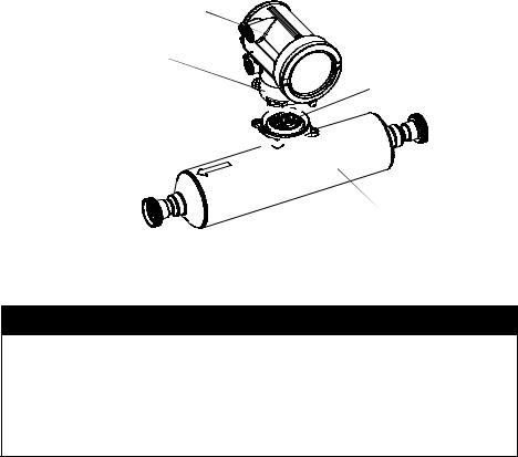
Installing the Transmitter
2.4.1Integral installations
If you chose an integral installation (see Figure 2-1), there are no special mounting instructions for the transmitter.
You can rotate an integrally mounted transmitter up to 360° in 90° increments, to one of four possible positions on the core processor base. See Figure 2-2.
Figure 2-2 Rotating the transmitter
Transmitter 
Transition ring
Core processor
4 X Cap screws (4 mm) 


 Base
Base 


 Sensor


 CAUTION
Damaging the wires that connect the transmitter to the core processor can cause measurement error or flowmeter failure.
To reduce the risk of damaging the wires, do not move the transmitter more than a few inches from the core processor. When reassembling the flowmeter, ensure that the wires will not be bent or pinched in the housing.
To rotate the transmitter on the core processor:
1.Loosen each of the four cap screws (4 mm) that fasten the transmitter to the base.
2.Rotate the transmitter counter-clockwise so that the cap screws are in the unlocked position.
3.Gently lift the transmitter straight up, disengaging it from the cap screws. Do not disconnect or damage the wires that connect the transmitter to the core processor.
4.Rotate the transmitter to the desired orientation, and align the slots with the cap screws. Do not pinch or stress the wires.
5.Gently lower the transmitter onto the base, inserting the cap screws into the slots.
6.Rotate the transmitter clockwise so that the cap screws are in the locked position.
7.Tighten the cap screws, torquing to 20 to 30 in-lbs (2,3 to 3,4 N-m).
|
10 |
Micro Motion® Model 1700 and 2700 Transmitters |
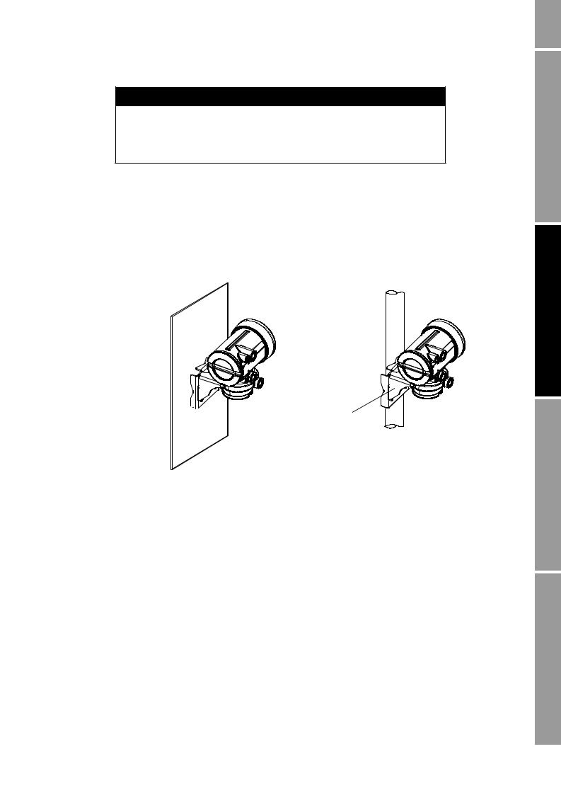
Installing the Transmitter


 CAUTION
Twisting the core processor will damage the sensor.
To reduce the risk of damaging the sensor, do not allow the core processor to rotate.
2.4.24-wire remote or remote core processor with remote transmitter installations
If you chose the 4-wire remote or the remote core processor with remote transmitter installation (see Figure 2-1), see Figure 2-3 for a diagram of the mounting bracket supplied with the transmitter. Both pipe mounting and wall mounting are shown. Ensure that the transmitter is mounted and oriented in a way that will allow easy access to the terminals and to the display (if your transmitter has a display).
Figure 2-3 4-wire remote – Wall mount or pipe mount
Mounting bracket 

 (wall mount)
To mount the transmitter:
Mounting bracket  (pipe mount)
Note: If possible, maintain 8–10″ (200–250 mm) clearance at the rear of the transmitter.
1.Identify the components shown in Figure 2-4. For dimensions, see Appendix A.
2.If desired, re-orient the transmitter on the bracket.
a.Remove the junction end-cap from the junction housing.
b.Loosen each of the four cap screws (4 mm) inside the junction housing.
c.Rotate the bracket so that the transmitter is oriented as desired.
d.Tighten the cap screws, torquing to 30 to 38 in-lbs (3 to 4 N-m).
e.Replace the junction end-cap.
3.Attach the mounting bracket to an instrument pole or wall. For pipe mount, two user-supplied U-bolts are required. Contact Micro Motion to obtain a pipe-mount installation kit if required.
Begin You Before
Transmitter the Installing
Wiring Sensor
Analog – Wiring Output
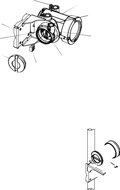
Installing the Transmitter
Figure 2-4 Transmitter components – 4-wire remote or remote core processor with remote transmitter installations
Ground screw
|
Main enclosure |
|
|
Conduit opening |
|
|
for 4-wire cable |
|
|
Mounting bracket |
|
|
4 X Cap screws |
Junction housing |
|
(4 mm) |
|
|
Junction end-cap |
Mating connector |
|
socket |
|
|
Mating connector |
2.4.39-wire remote installations
If you chose a 9-wire remote installation (see Figure 2-1), see Figure 2-5 for a diagram of the mounting bracket supplied with the transmitter/core processor assembly. Ensure that the transmitter is mounted and oriented in a way that will allow easy access to the terminals and to the display (if your transmitter has a display).
Figure 2-5 9-wire remote – Wall mount or pipe mount
Mounting bracket (wall mount)
Mounting bracket (pipe mount)
Note: If possible, maintain 8–10″ (200–250 mm) clearance at the rear of the transmitter.
|
12 |
Micro Motion® Model 1700 and 2700 Transmitters |
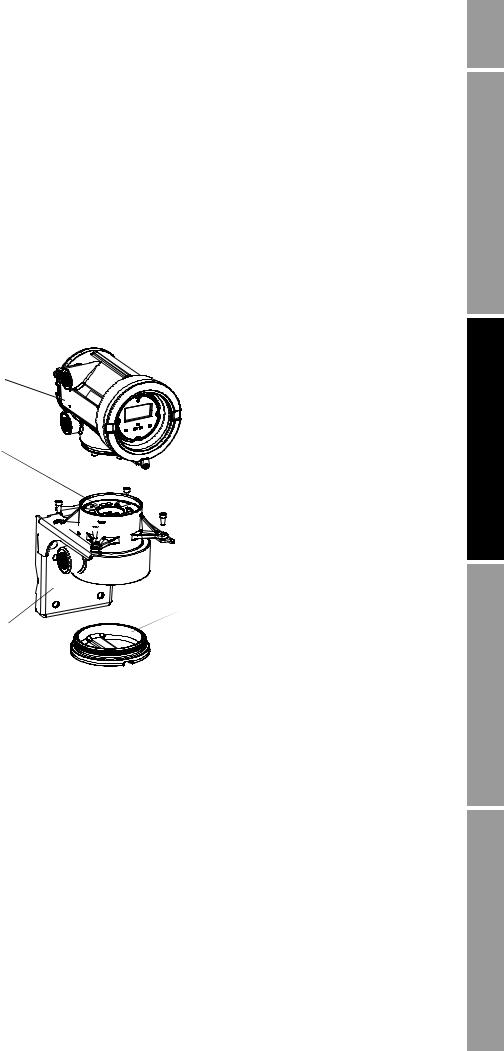
Installing the Transmitter
To mount the transmitter/core processor assembly:
1.Identify the components shown in Figure 2-6. For dimensions, see Appendix A.
2.If desired, re-orient the transmitter on the bracket.
a.Loosen each of the four cap screws (4 mm).
b.Rotate the bracket so that the transmitter is oriented as desired.
c.Tighten the cap screws, torquing to 30 to 38 in-lbs (3 to 4 N-m).
3.Attach the mounting bracket to an instrument pole or wall. For pipe mount, two user-supplied U-bolts are required. Contact Micro Motion to obtain a pipe-mount installation kit if required.
Figure 2-6 Transmitter/core processor assembly – Exploded view
Transmitter 
Core processor 
 4 × Cap screws (4 mm)
Core processor housing 


Conduit opening 

 for 9-wire cable
 End-cap
Mounting bracket 
2.5Mounting the remote core processor
Note: This step is required only for remote core processor with remote transmitter installations (see Figure 2-1). If you have an integral installation, 4-wire remote installation, or 9-wire remote installation, go to Section 2.6.
If you chose the remote core processor with remote transmitter installation (see Figure 2-1), see Figure 2-3 for a diagram of the mounting bracket supplied with the transmitter. Both pipe mounting and wall mounting are shown.
Begin You Before
Transmitter the Installing
Wiring Sensor
Analog – Wiring Output
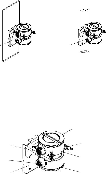
Installing the Transmitter
Figure 2-7 Remote core processor – Wall mount or pipe mount
|
Mounting bracket |
Mounting bracket |
|
(wall mount) |
(pipe mount) |
To mount the core processor:
1.Identify the components shown in Figure 2-8. For dimensions, see Appendix A.
2.If desired, reorient the core processor housing on the bracket.
a.Loosen each of the four cap screws (4 mm).
b.Rotate the bracket so that the core processor is oriented as desired.
c.Tighten the cap screws, torquing to 30 to 38 in-lbs (3 to 4 N-m).
3.Attach the mounting bracket to an instrument pole or wall. For pipe mount, two user-supplied U-bolts are required. Contact Micro Motion to obtain a pipe-mount installation kit if required.
Figure 2-8 Remote core processor components
|
Core processor lid |
|
|
Conduit opening |
4 × Cap screws (4 mm) |
|
for 4-wire cable |
|
|
Conduit opening |
Core processor housing |
|
for 9-wire cable |
|
|
Mounting bracket |
End-cap |
|
14 |
Micro Motion® Model 1700 and 2700 Transmitters |

Installing the Transmitter
2.6Grounding the flowmeter components
Grounding requirements depend on the installation type (see Figure 2-1). Grounding methods for each flowmeter component are listed in Table 2-3.


 CAUTION
Improper grounding could cause measurement error.
To reduce the risk of measurement error:
•Ground the transmitter to earth, or follow ground network requirements for the facility.
•For installation in an area that requires intrinsic safety, refer to Micro Motion approval documentation, shipped with the transmitter or available from the Micro Motion web site.
•For hazardous area installations in Europe, refer to standard EN 60079-14 if national standards do not apply.
If national standards are not in effect, follow these grounding guidelines:
•Use copper wire, 14 AWG (2,5 mm2) or larger wire size, for grounding.
•Keep all ground leads as short as possible, less than 1 Ω impedance.
•Connect ground leads directly to earth, or follow plant standards.
Table 2-3 Grounding methods for flowmeter components
|
Installation |
|||
|
architecture |
Components |
Grounding method |
|
|
Integral |
Sensor / core processor / |
Ground via piping, if possible (see sensor documentation). Otherwise, |
|
|
transmitter |
ground according to applicable local standards using either the |
||
|
transmitter’s internal or external ground screw. |
|||
|
4-wire remote |
Sensor / core processor |
See sensor documentation. |
|
|
assembly |
|||
|
Transmitter |
Ground according to applicable local standards, using either the |
||
|
transmitter’s internal or external ground screw. |
|||
|
9-wire remote |
Sensor / junction box |
See sensor documentation. |
|
|
Transmitter / core |
Ground according to applicable local standards, using either the |
||
|
processor assembly |
transmitter’s internal or external ground screw, or the core processor’s |
||
|
internal ground screw. |
|||
|
Remote core |
Sensor |
See sensor documentation. |
|
|
processor with |
|||
|
Core processor |
Ground according to applicable local standards, using either the internal |
||
|
remote |
|||
|
or external ground screw. |
|||
|
transmitter |
|||
|
Transmitter |
Ground according to applicable local standards, using either the |
||
|
transmitter’s internal or external ground screw. |
|||
Begin You Before
Transmitter the Installing
Wiring Sensor
Analog – Wiring Output
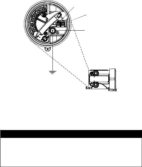
Installing the Transmitter
2.7Supplying power
In all installations, power must be provided to the transmitter. Refer to Section 2.3.3 for information on the transmitter’s power supply requirements.
A user-supplied switch may be installed in the power supply line. For compliance with low-voltage directive 2006/95/EC (European installations), a switch in close proximity to the transmitter is required.
Connect the power supply to terminals 9 and 10, under the Warning flap. Terminate the positive (line) wire on terminal 10 and the return (neutral) wire on terminal 9. Ground the power supply using the equipment ground, also under the Warning flap. See Figure 2-9.
Figure 2-9 Wiring the transmitter power supply
 9
9
 10
10
Equipment ground
Warning flap 
2.8Rotating the display
If your transmitter has a display, you can rotate the display on the transmitter up to 360° in 90° increments.


 WARNING
Removing the display cover in explosive atmospheres while the power is on can cause an explosion.
To reduce the risk of an explosion, before removing the display cover in explosive atmospheres, be sure to shut off the power and wait five minutes.
|
16 |
Micro Motion® Model 1700 and 2700 Transmitters |
![]()
Installing the Transmitter


 WARNING
Using a dry cloth to clean the display cover can cause static discharge, which could result in an explosion in an explosive atmosphere.
To reduce the risk of an explosion, always use a damp cloth to clean the display cover in an explosive atmosphere.
To rotate the display, follow the instructions below:
1.Power down the transmitter.
2.Remove the end-cap clamp by removing the cap screw. See Figure 2-10.
3.Turn the display cover counterclockwise to remove it from the main enclosure.
4.Carefully loosen (and remove if necessary) the semicaptive display screws while holding the display module in place.
5.Carefully pull the display module out of the main enclosure until the sub-bezel pin terminals are disengaged from the display module.
Note: The display pins may come out of the board stack with the display module. If this happens, simply remove the pins and reinstall them.
6.Rotate the display module to the desired position.
7.Insert the sub-bezel pin terminals into the display module pin holes to secure the display in its new position.
8.If you have removed the display screws, line them up with the matching holes on the sub-bezel, then reinsert and tighten them.
9.Place the display cover onto the main enclosure. Turn the display cover clockwise until it is snug.
10.Replace the end-cap clamp by reinserting and tightening the cap screw.
11.Restore power to the transmitter.
Begin You Before
Transmitter the Installing
Wiring Sensor
Analog – Wiring Output
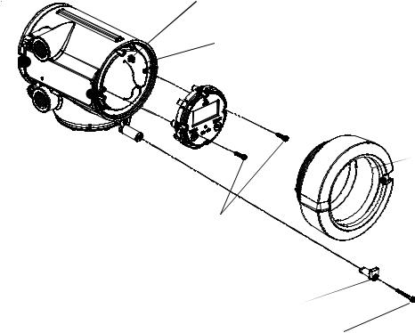
Installing the Transmitter
Figure 2-10 Display components
|
Main enclosure |
Pin terminals |
 Sub-bezel
Display module
Display cover
Display screws 
End-cap clamp 
Cap screw 
|
18 |
Micro Motion® Model 1700 and 2700 Transmitters |

Chapter 3
Wiring the Transmitter to the Sensor
3.1Overview
This chapter describes how to connect Micro Motion Model 1700 and 2700 transmitters to a Micro Motion sensor.
Note: If you have an integral installation, this step is not required. Continue with wiring the transmitter outputs (Chapters 4–7).
Wiring requirements between the sensor and transmitter depend on the installation type (see Figure 2-1).
•If you have a 4-wire remote transmitter installation, review the information on 4-wire cable in Section 3.2, then follow the instructions in Section 3.3.
•If you have a 9-wire remote transmitter installation, review the information on 9-wire cable in Section 3.2, then follow the instructions in Section 3.4.
•If you have a remote core processor with remote transmitter installation, review the information on both 4-wire and 9-wire cable in Section 3.2, then follow the instructions in Section 3.5.


 CAUTION
Large electromagnetic fields can interfere with flowmeter communication signals.
Improper installation of cable or conduit can cause measurement error or flowmeter failure. To reduce the risk of measurement error or flowmeter failure, keep cable or conduit away from devices such as transformers, motors, and power lines which produce large electromagnetic fields.
3.2Cable types
This section describes the types of 4-wire cable and 9-wire cable that can be used for wiring the transmitter to the sensor.
Begin You Before
Transmitter the Installing
Wiring Sensor
Analog – Wiring Output
Wiring the Transmitter to the Sensor
3.2.14-wire cable
Micro Motion offers two types of 4-wire cable: shielded and armored. Both types contain shield drain wires.
User-supplied 4-wire cable must meet the following requirements:
•Twisted pair construction
•The gauge requirements as described in Table 2-2
•The applicable hazardous area requirements, if the core processor is installed in a hazardous area (see the approval documentation shipped with the transmitter or available on the Micro Motion web site)
3.2.29-wire cable
Micro Motion offers three types of 9-wire cable: jacketed, shielded, and armored. Refer to Micro Motion’s 9-Wire Flowmeter Cable Preparation and Installation Guide for detailed descriptions of these cable types and for assistance in selecting the appropriate cable for your installation.
3.3Wiring for 4-wire remote installations
To connect the cable, follow the steps below.
1.Prepare the cable as described in the sensor documentation.
2.Connect the cable to the core processor as described in the sensor documentation.
3.To connect the cable to the transmitter:
a.Identify the wires in the 4-wire cable. The 4-wire cable supplied by Micro Motion consists of one pair of 18 AWG (0,75 mm2) wires (red and black), which should be used for the VDC connection, and one pair of 22 AWG (0,35 mm2) wires (green and white), which should be used for the RS-485 connection.
b.Connect the four wires from the core processor to terminals 1–4 on the mating connector of the transmitter. See Figures 3-1, 3-2, and 3-3. Never ground the shield, braid, or drain wire(s) at the transmitter.
Figure 3-1 4-wire cable between enhanced core processor and transmitter
|
Core processor |
4-wire cable |
Mating connector |
|
terminals |
Maximum cable length: see Table 2-2 |
(transmitter) |
|
VDC+ |
||
|
User-supplied or |
VDC– |
|
|
RS-485A |
||
|
factory-supplied cable |
||
|
RS-485B |
||
|
VDC+ (Red) VDC– (Black) RS-485A (white) RS-485B (Green) |
|
20 |
Micro Motion® Model 1700 and 2700 Transmitters |
 Loading…