- Manuals
- Brands
- METREL Manuals
- Measuring Instruments
- power master MI 2892
- Instruction manual
-
Contents
-
Table of Contents
-
Troubleshooting
-
Bookmarks
Quick Links
Power Master
MI 2892
Instruction manual
Version 1.1, Code No. 20 752 217
Related Manuals for METREL power master MI 2892
Summary of Contents for METREL power master MI 2892
-
Page 1
Power Master MI 2892 Instruction manual Version 1.1, Code No. 20 752 217… -
Page 2
Mark on your equipment certifies that this equipment meets the requirements of the EU (European Union) concerning safety and interference causing equipment regulations © 2013 METREL No part of this publication may be reproduced or utilized in any form or by any means without permission in writing from METREL. -
Page 3: Table Of Contents
MI 2892 Power Master Table of contents Introduction ………………….7 Main Features ………………..7 Safety considerations ………………8 Applicable standards ………………9 Abbreviations ………………..10 Description ………………….19 Front panel ………………….
-
Page 4
MI 2892 Power Master Table of contents 3.15 Transient recorder ………………. 62 3.15.1 Setup ………………….62 3.15.2 Capturing transients …………….. 63 3.15.3 Captured transients ……………… 65 3.16 Events table ………………… 66 … -
Page 5
MI 2892 Power Master Table of contents 5.1.11 Voltage events ………………136 5.1.12 Alarms ………………..139 5.1.13 Data aggregation in GENERAL RECORDING ……..139 5.1.14 Waveform snapshot …………….142 5.1.15 Waveform record ………………143 … -
Page 6
MI 2892 Power Master Table of contents Maintenance ………………….161 Inserting batteries into the instrument …………161 Batteries ………………….162 Power supply considerations …………….. 163 Cleaning ………………….164 Periodic calibration ………………164 … -
Page 7: Introduction
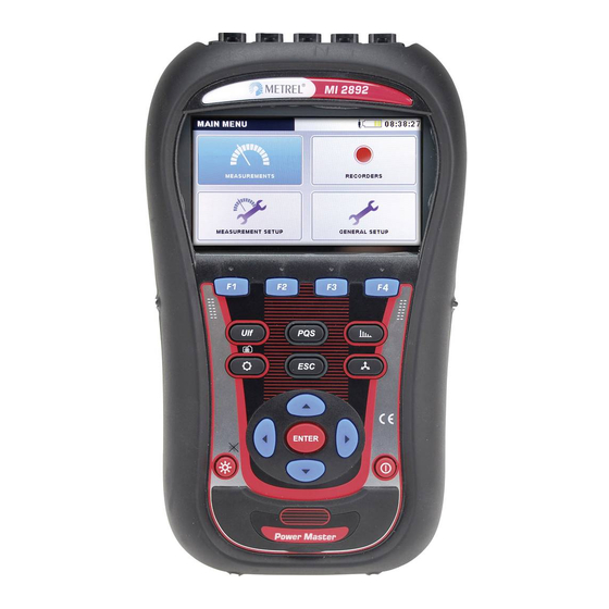
MI 2892 Power Master Introduction 1 Introduction Power Master is handheld multifunction instrument for power quality analysis and energy efficiency measurements. Figure 1.1: Power Master instrument 1.1 Main Features Full compliance with power quality standard IEC 61000-4-30 Class A. …
-
Page 8: Safety Considerations
MI 2892 Power Master Introduction 4.3’’ TFT colour display, easy internet remote access over Ethernet. Waveform/inrush recorder, which can be triggered on event or alarms, and run simultaneously with general recorder. Powerful troubleshooting tools: transient recorder with envelope and level triggering.
-
Page 9: Applicable Standards
MI 2892 Power Master Introduction Maximum nominal voltage between any phase and neutral input is 1000 V Maximum nominal voltage between phases is 1730 V Always short unused voltage inputs (L1, L2, L3, GND) with neutral (N) input to prevent measurement errors and false event triggering due to noise coupling. Do not remove microSD memory card while instrument is recording or reading data.
-
Page 10: Abbreviations
MI 2892 Power Master Introduction General guide on harmonics and interharmonics measurements and instrumentation for power supply systems and equipment connected thereto IEC 61000-4-15 : 2010 Part 4-15: Testing and measurement techniques – Flickermeter – Functional design specifications IEC 62053-22 : 2003 Part 22: Static meters for active energy (Class 0.5S) IEC 62053-23 : 2003…
-
Page 11
MI 2892 Power Master Introduction Recorded phase displacement (fundamental) power factor or cos , including DPFp (phase p power ind/cap displacement). Minus sign indicates generated power and plus sign indicates ind/cap consumed power. Suffix cap- ind+ ind/cap represents inductive/ capacitive character. -
Page 12
MI 2892 Power Master Introduction section: Power measurement (Standard compliance: IEEE 1459-2010) for definition. Recorded phase combined (fundamental nonfundamental) active energy, including Ep (phase p active energy). Minus sign indicates generated energy and plus sign indicates consumed energy. See 5.1.6 for definition. -
Page 13
MI 2892 Power Master Introduction Nominal current. Current of clamp-on current sensor for 1 Vrms at output. Peak current, including I (phase p current) including I (neutral peak current) RMS current, including I (phase p current), I pRms NRms (neutral RMS current). See 5.1.3 for definition. Instantaneous phase active… -
Page 14
MI 2892 Power Master Introduction Instantaneous phase active harmonic power, including (phase p active harmonic power). Minus sign indicates generated and plus sign indicates consumed power. See 5.1.5 for definitions. Recorded phase active harmonics power, including P … -
Page 15
MI 2892 Power Master Introduction Recorded total effective combined (fundamental and nonfundamental) power factor. Minus sign indicates generated power and plus sign indicates consumed power. totind Suffix ind/cap represents totcap totind totcap inductive/capacitive character. This parameter is recorded totcap totind separately for each quadrant… -
Page 16
MI 2892 Power Master Introduction Recorded phase fundamental reactive power. Suffix ind/cap represents inductive/capacitive character. Minus sign indicates Qfund generated plus sign indicates consumed Qfund fundamental reactive power. This parameter is recorded separately for each quadrant as shown on figure. See 5.1.5 for definition. Instantaneous positive sequence of total fundamental reactive power. -
Page 17
MI 2892 Power Master Introduction Total harmonic distortion voltage related (in % or V) including THD (phase p to phase g voltage THD) and (phase p to neutral voltage THD). See 5.1.10 for definition. Negative sequence voltage ratio (%). See 5.1.10 for definition. -
Page 18
MI 2892 Power Master Introduction Maximal voltage measured during swell Swell Rms½ occurrence. Mains signalling RMS voltage, including U (phase p to Sigpg phase g half-cycle signalling voltage) and U (phase p to neutral half-cycle signalling voltage). Signalling is a burst of signals, often applied at a non-harmonic frequency, that remotely control equipment. -
Page 19: Description
MI 2892 Power Master Description 2 Description 2.1 Front panel Figure 2.1: Front panel Front panel layout: Colour TFT display, 4.3 inch, 480 x 272 pixels. 1. LCD Function keys. 2. F1 – F4 Moves cursor and select parameters. 3. ARROW keys Step into submenu.
-
Page 20: Connector Panel
MI 2892 Power Master Description Turns on/off the instrument. 8. ON-OFF key Communication ports and microSD card slot protection. 9. COVER 2.2 Connector panel Warnings! Use safety test leads only! Max. permissible nominal voltage between voltage input terminals and ground is 1000 V Max.
-
Page 21: Bottom View
MI 2892 Power Master Description 2.3 Bottom view Figure 2.4: Bottom view Bottom view layout: 1. Battery compartment cover. 2. Battery compartment screw (unscrew to replace the batteries). 3. Serial number label. 2.4 Accessories 2.4.1 Standard accessories Table 2.1: Power Master standard accessories Description Pieces Flexible current clamp 3000 A / 300 A / 30 A (A 1227)
-
Page 22: Operating The Instrument
MI 2892 Power Master Operating the instrument 3 Operating the instrument This section describes how to operate the instrument. The instrument front panel consists of a colour LCD display and keypad. Measured data and instrument status are shown on the display. Basic display symbols and keys description is shown on figure below.
-
Page 23: Instrument Status Bar
MI 2892 Power Master Operating the instrument 3.1 Instrument status bar Instruments status bar is placed on the top of the screen. It indicates different instrument states. Icon descriptions are shown on table below. Figure 3.3: Instrument status bar Table 3.1: Instrument status bar description Indicates battery charge level.
-
Page 24: Instrument Keys
MI 2892 Power Master Operating the instrument 3.2 Instrument keys Instrument keyboard is divided into four subgroups: Function keys Shortcut keys Menu/zoom manipulation keys: Cursors, Enter, Escape Other keys: Light and Power on/off keys Function keys are multifunctional. Their current function is shown at the bottom of the screen and depends on selected instrument function.
-
Page 25: Instrument Main Menu
MI 2892 Power Master Operating the instrument Figure 3.4: Inserting microSD card 1. Open instrument cover 2. Insert microSD card into a slot on the instrument (card should be putted upside down, as shown on figure) 3. Close instrument cover Note: Do not turn off the instrument while miroSD card is accessed: during record session observing recorded data in MEMORY LIST menu…
-
Page 26: Instrument Submenus
MI 2892 Power Master Operating the instrument Figure 3.5: “MAIN MENU” Table 3.3: Instrument Main menu MEASUREMENT submenu. Provide access to various instrument measurement screens RECORDER submenu. Provide access to instrument recorders configuration and storage. MEASUREMENT SETUP submenu. Provide access to the measurement settings.
-
Page 27
MI 2892 Power Master Operating the instrument Figure 3.6: Measurements submenu Figure 3.7: Recorders submenu Figure 3.8: Measurement setup submenu… -
Page 28: U, I, F
MI 2892 Power Master Operating the instrument Figure 3.9: General setup submenu Table 3.5: Keys in submenus Selects function within each submenu. Enters selected function. ENTER Returns to the “MAIN MENU”. 3.5 U, I, f Voltage, current and frequency parameters can be observed in the “U, I, f” screens. Measurement results can be viewed in a tabular (METER) or a graphical form (SCOPE, TREND).
-
Page 29
MI 2892 Power Master Operating the instrument Figure 3.11: U, I, f meter summary table screens In those screens on-line voltage and current measurements are shown. Descriptions of symbols and abbreviations used in this menu are shown in table below. Table 3.6: Instrument screen symbols and abbreviations True effective value U and I… -
Page 30: Scope
MI 2892 Power Master Operating the instrument Table 3.7: Keys in Meter screens HOLD Holds measurement on display. Runs held measurement. RESET Resets MAX and MIN values (U and I Rms½ Rms½ Shows measurements for phase L1. 2 3 N Δ…
-
Page 31
MI 2892 Power Master Operating the instrument Figure 3.14: Voltage and current Figure 3.15: Voltage and current waveform (single mode) waveform (dual mode) Table 3.8: Instrument screen symbols and abbreviations U1, U2, U3, Un True effective value of phase voltage: U12, U23, U31 True effective value of phase-to-phase (line) voltage: I1, I2, I3, In… -
Page 32: Trend
MI 2892 Power Master Operating the instrument METER Switches to METER view. SCOPE Switches to SCOPE view. TREND Switches to TREND view (available only during recording). Selects which waveform to zoom (only in U/I or U+I). ENTER Sets vertical zoom. Sets horizontal zoom.
-
Page 33
MI 2892 Power Master Operating the instrument (single mode) (dual mode) Figure 3.20: Trends of all currents Figure 3.21: Frequency trend Table 3.10: Instrument screen symbols and abbreviations U1, U2, U3, Maximal ( ), average ( ) and minimal ( ) value of phase RMS voltage Un, U12, or line voltage U for time interval (IP) -
Page 34: Power
MI 2892 Power Master Operating the instrument Shows trend for phases L23. Δ Shows trend for phases L31. 12 23 Δ Shows all phase-to-phase trends. Δ 12 23 31 Switches to METER view. METER SCOPE Switches to SCOPE view. TREND Switches to TREND view.
-
Page 35
MI 2892 Power Master Operating the instrument Description of symbols and abbreviations used in POWER (METER) screens are shown in table below. Table 3.12: Instrument screen symbols and abbreviations Depending on the screen position: In Combined column: Instantaneous combined (fundamental and … -
Page 36: Trend
MI 2892 Power Master Operating the instrument Table 3.13: Keys in Power (METER) screens HOLD Holds measurement on display. Runs held measurement. Switches between Combined, Fundamental and VIEW Nonfundamental view. Shows measurements for phase L1. 2 3 T Shows measurements for phase L2. 3 T Shows measurements for phase L3.
-
Page 37
MI 2892 Power Master Operating the instrument Maximal ( ), average ( ) and minimal ( ) value of consumed Ni1±, Ni2±, ) or generated (N 1ind 2ind 3ind totind 1ind 2ind 3ind Ni3±, Nit± ) inductive combined nonactive power for time interval (IP) totind selected by cursor. -
Page 38
MI 2892 Power Master Operating the instrument Maximal ( ), average ( ) and minimal ( ) value of consumed Ph1±, Ph2±, ) or generated (P ) active Htot Htot Ph3±, Pht± harmonic power for time interval (IP) selected by cursor. Table 3.15: Keys in Power (TREND) screens Selects which… -
Page 39: Energy
MI 2892 Power Master Operating the instrument Shows nonfundamental voltage distortion power. Sn Di Shows nonfundamental active power. Sn Di Dv Selects between phase, all-phases and Total power view: Shows power parameters for phase L1. 2 3 T Shows power parameters for phase L2. 3 T Shows power parameters for phase L3.
-
Page 40: Trend
MI 2892 Power Master Operating the instrument Start Recorder start time and date Duration Recorder elapsed time Table 3.17: Keys in Energy (METER) screens HOLD Holds measurement on display. Runs held measurement. Shows energy registers for whole record. LAST CUR LAST Shows energy registers for last interval.
-
Page 41: Harmonics / Interharmonics
MI 2892 Power Master Operating the instrument Start Recorder start time and date Duration Recorder elapsed time Table 3.19: Keys in Energy (TREND) screens Shows active consumed energy for time interval (IP) Eq+ Ep- Eq- selected by cursor. Shows reactive consumed energy for time interval (IP) Ep- Eq- selected by cursor.
-
Page 42
MI 2892 Power Master Operating the instrument Figure 3.29: Harmonics and interharmonics (METER) screens Description of symbols and abbreviations used in METER screens are shown in table below. Table 3.20: Instrument screen symbols and abbreviations Total voltage / current harmonic distortion THD and THD in % of fundamental voltage / current harmonic or in RMS V, A. -
Page 43: Histogram (Bar)
MI 2892 Power Master Operating the instrument Shows harmonics / interharmonics components for phase L2. 3 N Δ Shows harmonics / interharmonics components for phase L3. N Δ Shows harmonics / interharmonics components for neutral 1 2 3 …
-
Page 44
MI 2892 Power Master Operating the instrument Table 3.22: Instrument screen symbols and abbreviations Ux h01 … h50 Voltage harmonic / interharmonic component in V and in % of fundamental voltage Ix h01 … h50 Current harmonic / interharmonic component in A and in % of fundamental current Ux DC… -
Page 45: Trend
MI 2892 Power Master Operating the instrument Scrolls cursor to select single harmonic / interharmonic bar. Toggles cursor between voltage and current histogram. ENTER Triggers Waveform snapshot. Returns to the “MEASUREMENTS” submenu. 3.8.3 Trend During active GENERAL RECORDER, TREND view is available (see section 3.13 for instructions how to start GENERAL RECORDER).
-
Page 46
MI 2892 Power Master Operating the instrument for selected phase Uh/Uih Maximal ( ) and average ( ) value for selected n-th voltage harmonic / interharmonic component for selected phase Ih/Iih Maximal ( ) and average ( )value of selected n-th current harmonic / interharmonic component for selected phase Table 3.25: Keys in Harmonics / interharmonics (TREND) screens Switches between harmonics or interharmonics view. -
Page 47: Flickers
MI 2892 Power Master Operating the instrument Moves cursor and select time interval (IP) for observation. Returns to the “MEASUREMENTS” submenu. 3.9 Flickers Flickers measure the human perception of the effect of amplitude modulation on the mains voltage powering a light bulb. In Flickers menu instrument shows measured flicker parameters.
-
Page 48: Trend
MI 2892 Power Master Operating the instrument Triggers Waveform snapshot. Returns to the “MEASUREMENTS” submenu. 3.9.2 Trend During active recording TREND view is available (see section 3.13 for instructions how to start recording). Flicker parameters can be observed by cycling function key F4 (METER -TREND).
-
Page 49
MI 2892 Power Master Operating the instrument Table 3.28: Instrument screen symbols and abbreviations Pst1m1, Pst1m2, Maximal ( ), average ( ) and minimal ( ) value of 1-minute short Pst1m3, term flicker P for phase voltages U or line voltages st(1min) Pst1m12, Pst1m23,… -
Page 50: Phase Diagram
MI 2892 Power Master Operating the instrument 3.10 Phase Diagram Phase diagram graphically represent fundamental voltages, currents and phase angles of the network. This view is strongly recommended for checking instrument connection before measurement. Note that most measurement issues arise from wrongly connected instrument (see 4.1 for recommended measuring practice).
-
Page 51: Unbalance Diagram
MI 2892 Power Master Operating the instrument Scales voltage or current phasors. Triggers Waveform snapshot. Returns to the “MEASUREMENTS” submenu. 3.10.2 Unbalance diagram Unbalance diagram represents current and voltage unbalance of the measuring system. Unbalance arises when RMS values or phase angles between consecutive phases are not equal.
-
Page 52: Unbalance Trend
MI 2892 Power Master Operating the instrument Table 3.33: Keys in Unbalance diagram screens HOLD Holds measurement on display. Runs held measurement. Shows voltage unbalance measurement and selects voltage for scaling (with cursors) Shows current unbalance measurement and selects current for scaling (with cursors) METER Switches to PHASE DIAGRAM view.
-
Page 53: Temperature
MI 2892 Power Master Operating the instrument Maximal ( ), average ( ) and minimal ( ) value of zero sequence voltage U Maximal ( ), average ( ) and minimal ( ) value of positive sequence current I Maximal ( ), average ( ) and minimal ( ) value of negative sequence current I Maximal ( ), average ( ) and minimal ( ) value of zero sequence current I…
-
Page 54: Trend
MI 2892 Power Master Operating the instrument Table 3.37: Keys in Temperature meter screen HOLD Holds measurement on display. Runs held measurement. METER Switches to METER view. TREND Switches to TREND view (available only during recording). Triggers Waveform snapshot. Returns to the “MEASUREMENTS” submenu. 3.11.2 Trend Temperature measurement TREND can be viewed during the recording in progress.
-
Page 55: Meter
MI 2892 Power Master Operating the instrument Results can be seen in a tabular (METER) or a graphical form (TREND) — which is active only while GENERAL RECORDER is active. See section 3.13 for instructions how to start recording. In order to understand meanings of particular parameter see section 5.1.8.
-
Page 56: Trend
MI 2892 Power Master Operating the instrument 3.12.2 Trend During active recording TREND view is available (see section 3.13 for instructions how to start recording). Signalling parameters can be observed by cycling function key F4 (METER -TREND). Figure 3.40: Signalling trend screen Table 3.42: Instrument screen symbols and abbreviations Maximal ( ), average ( ) and minimal ( ) value of (U Sig1…
-
Page 57: General Recorder
MI 2892 Power Master Operating the instrument METER Switches to METER view. TREND Switches to TREND view (available only during recording). Moves cursor and select time interval (IP) for observation. Returns to the “MEASUREMENTS” submenu. 3.13 General Recorder Power Master has ability to record measured data in the background. By entering GENERAL RECORDER option from RECORDERS submenu, recorder parameters can be customized in order to meet criteria about interval, and the number of signals for the recording campaign.
-
Page 58: Waveform/Inrush Recorder
MI 2892 Power Master Operating the instrument Keys in Set start time window: Selects parameter to be changed. Modifies parameter. Confirms selected option. ENTER Exits Set start time window without modifications. Selects parameter to be changed. Modifies parameter. Returns to the “RECORDERS” submenu. 3.14 Waveform/inrush recorder Waveform recording is a powerful tool for troubleshooting and capturing current and…
-
Page 59: Capturing Waveform
MI 2892 Power Master Operating the instrument Table 3.46: Waveform recorder settings description and screen symbols Waveform recorder is active, waiting for trigger Waveform recorder is active, recording in progress Trigger source set up: Events – triggered by voltage event (see 3.19.2); …
-
Page 60
MI 2892 Power Master Operating the instrument Figure 3.44: Waveform recorder capture screen Table 3.48: Instrument screen symbols and abbreviations Waveform recorder is active, waiting for trigger Waveform recorder is active, recording in progress U1, U2, U3, Un True effective value of phase voltage: U 1Rms 2Rms 3Rms… -
Page 61: Captured Waveform
MI 2892 Power Master Operating the instrument Sets horizontal zoom. Returns to the “WAVEFORM RECORDER” setup screen. 3.14.3 Captured waveform Captured waveforms can be viewed from the Memory list menu. Figure 3.45: Captured waveform recorder screen Table 3.50: Instrument screen symbols and abbreviations Memory list recall.
-
Page 62: Transient Recorder
MI 2892 Power Master Operating the instrument Shows waveforms for phase to phase voltage L12. 23 31 Δ Shows waveforms for phase to phase voltage L23. 31 Δ Shows waveforms for phase to phase voltage L31. 12 23 Δ Shows all phase-to-phase waveforms. Δ…
-
Page 63: Capturing Transients
MI 2892 Power Master Operating the instrument Level Envelope voltage level Trigger will occur if any sample within period is greater than defined absolute trigger level. See 5.1.16 for details. Trigger (Level U) Level Absolute trigger level in voltage Duration Record length.
-
Page 64
MI 2892 Power Master Operating the instrument Figure 3.47: Transient recorder capture screen Table 3.54: Instrument screen symbols and abbreviations Transient recorder is active, waiting for trigger Transient recorder is active, recording in progress U1, U2, U3, Un True effective value of phase voltage: U 1Rms 2Rms 3Rms… -
Page 65: Captured Transients
MI 2892 Power Master Operating the instrument Returns to the “TRANSIENT RECORDER” setup screen. 3.15.3 Captured transients Captured transient records can be viewed from the Memory list where captured waveforms can be analysed. Trigger occurrence is marked with the blue line, while cursor position line is marked in black.
-
Page 66: Events Table
MI 2892 Power Master Operating the instrument Shows waveforms for all phase-to-phase voltages. Δ 12 23 31 ZOOM Sets horizontal zoom Sets vertical zoom. Moves cursor. Toggles cursor between voltage and current (only in U,I or U/I). ENTER Returns to the “MEMORY LIST” submenu. 3.16 Events table In this table captured voltage dips, swells and interrupts are shown.
-
Page 67
MI 2892 Power Master Operating the instrument Figure 3.50: Voltage events in detail view screen Table 3.58: Instrument screen symbols and abbreviations Date Date when selected event has occurred Unified event number (ID) Indicate phase or phase-to-phase voltage where event has occurred: 1 –… -
Page 68
MI 2892 Power Master Operating the instrument EVENTS Returns to “EVENTS” view. Selects event. Enters detail event view. ENTER Returns to Events table group view screen. Returns to “RECORDERS” submenu. Phase view In this view voltage events are separated by phases. This is convenient view for troubleshooting. -
Page 69
MI 2892 Power Master Operating the instrument 1 – event on phase U 2 – event on phase U 3 – event on phase U 12 – event on voltage U 23 – event on voltage U 31 – event on voltage U Start Event start time (when first U ) value crosses threshold. -
Page 70: Alarms Table
MI 2892 Power Master Operating the instrument EVENTS Returns to EVENTS view. Selects event. Enters detail event view. ENTER Returns to Events table phase view screen. Returns to the “RECORDERS” submenu. 3.17 Alarms table This screen shows list of alarms which went off. Alarms are displayed in a table, where each row represents an alarm.
-
Page 71
MI 2892 Power Master Operating the instrument Fall – parameter has under-crossed threshold Min/Max Minimal or maximal parameter value during alarm occurrence Duration Alarm duration. Table 3.63: Keys in Alarms table screens Filters alarms according to the following parameters: … -
Page 72: Memory List
MI 2892 Power Master Operating the instrument Returns to the “RECORDERS” submenu. 3.18 Memory List Using this menu user can view and browse saved records. By entering this menu, information about records is shown. Figure 3.53: Memory list screen Table 3.64: Instrument screen symbols and abbreviations Selected record number, for which details are shown.
-
Page 73: General Record
MI 2892 Power Master Operating the instrument Selects YES or NO. Confirms selection. ENTER Exits confirmation window without clearing saved records. Browses through records (next or previous record). Returns to the “RECORDERS” submenu. 3.18.1 General Record This type of record is made by GENERAL RECORDER. Record front page is similar to the GENERAL RECORDER setup screen, as shown on figure below.
-
Page 74
MI 2892 Power Master Operating the instrument Keys in CHANNELS SETUP menu screen: Selects particular signal group. Enters particular signal group (TREND view). ENTER Exits to MEMORY LIST menu. CLEAR Clears the last record. In order to clear complete memory, delete records one by one. Opens confirmation window for clearing all saved records. -
Page 75
MI 2892 Power Master Operating the instrument Figure 3.55: Viewing recorder U,I,f TREND data Table 3.68: Instrument screen symbols and abbreviations Memory list recall. Shown screen is recalled from memory. Indicates position of the cursor at the graph. U1, U2 U3, Maximal ( ), average ( ) and minimal ( ) recorded value of phase voltage U , for time interval selected by cursor. -
Page 76: Waveform Snapshot
MI 2892 Power Master Operating the instrument Shows trend for phases L23. Δ Shows trend for phases L31. 12 23 Δ Shows all phase to phase trends. Δ 12 23 31 Moves cursor and select time interval (IP) for observation. Returns to the “CHANNELS SETUP”…
-
Page 77
MI 2892 Power Master Operating the instrument Keys in CHANNELS SETUP menu screen: Selects particular signal group. Enters particular signal group (METER or SCOPE view). ENTER Exits to MEMORY LIST menu. CLEAR Clears the last record. In order to clear complete memory, delete records one by one. -
Page 78: Waveform/Inrush Record
MI 2892 Power Master Operating the instrument Note: For more details regarding manipulation and data observing see previous sections of this manual. 3.18.3 Waveform/inrush record This type of record is made by Waveform recorder. For details regarding manipulation and data observing see section Captured waveform 3.14.3. 3.18.4 Transients record This type of record is made by Transient recorder.
-
Page 79: Connection Setup
MI 2892 Power Master Operating the instrument 3.19.1 Connection setup Figure 3.59: “CONNECTION SETUP” screen Table 3.74: Description of Connection setup Set nominal voltage. Select voltage according to the network voltage. If voltage is measured over potential transformer then press ENTER for setting transformer parameters: Nominal voltage Voltage ratio: Potential transformer ratio Δ :…
-
Page 80
MI 2892 Power Master Operating the instrument Note: For Smart clamps (A 1227, A 1281) always select “Smart clamps”. Note: See section 4.2.3 for details regarding further clamps settings. Method of connecting the instrument to multi-phase systems (see 4.2.1 for details). … -
Page 81
MI 2892 Power Master Operating the instrument Synchronization channel. This channel is used for instrument synchronization to the network frequency. Also a frequency measurement is performed on that channel. Depending on Connection user can select: Synchronization 1W: U1 or I1. … -
Page 82: Event Setup
MI 2892 Power Master Operating the instrument Enters into submenu. ENTER Confirms Factory reset. Returns to the “MEASUREMENT SETUP” submenu. 3.19.2 Event setup In this menu user can setup voltage events and their parameters. See 5.1.11 for further details regarding measurement methods. Captured events can be observed through EVENTS TABLE screen.
-
Page 83
MI 2892 Power Master Operating the instrument Figure 3.61: Alarm setup screens Table 3.78: Description of Alarm setup column — Select alarm from measurement group then measurement itself. Quantity (P+, Uh5, I, on figure above) column — Select phases for alarms capturing … -
Page 84: Signalling Setup
MI 2892 Power Master Operating the instrument Clears selected or all alarms: REMOVE Edits selected alarm. EDIT Enters or exits a submenu to set an alarm. ENTER Cursor keys. Selects parameter or changes value. Cursor keys. Selects parameter or changes value. Confirms setting of an alarm.
-
Page 85: Communication
MI 2892 Power Master Operating the instrument Figure 3.63: GENERAL SETUP submenu Table 3.81: Description of General setup options Communication Setup communication source and baud rate. Time & Date Set time, date and time zone. Language Select language. Instrument info Information about the instrument.
-
Page 86: Time & Date
MI 2892 Power Master Operating the instrument Table 3.83: Description of Communication setup options PC connection Select RS-232, USB or INTERNET communication port. Enable GPS if used for time synchronisation. Valid only if INTERNET communication is selected. Secret number will assure additional protection of Secret key communication link.
-
Page 87: Language
MI 2892 Power Master Operating the instrument Table 3.85: Description of Set date/time screen Show clock source: RTC – internal real time clock Clock source GPS – external GPS receiver Note: GPS clock source is automatically set if GPS is enabled and detected.
-
Page 88: Instrument Info
MI 2892 Power Master Operating the instrument Figure 3.66: Language setup screen Table 3.87: Keys in Language setup screen Selects language. Confirms the selected language. ENTER Returns to the “GENERAL SETUP” submenu. 3.20.5 Instrument info Basic information concerning the instrument (company, user data, serial number, firmware version and hardware version) can be viewed in this menu.
-
Page 89
MI 2892 Power Master Operating the instrument Figure 3.68: Lock/Unlock screen Table 3.89: Description of Lock/Unlock screen Four digit numeric code used for Locking/Unlocking the instrument. Press ENTER key for changing the Pin code. “Enter PIN” window will appear on screen. Note: Pin code is hidden (****), if the instrument is locked. -
Page 90: Colour Model
MI 2892 Power Master Operating the instrument Figure 3.69: Locked instrument screen Note: In case user forget unlock code, general unlock code “7350” can be used to unlock the instrument. 3.20.7 Colour model In COLOUR MODEL menu, user can change colour representation of phase voltages and currents, according to the customer needs.
-
Page 91
MI 2892 Power Master Operating the instrument Keys in Edit colour screen: Shows selected colour for phase L1. L2 L3 N Shows selected colour for phase L2. L3 N Shows selected colour for phase L3. L1 L2 Shows selected colour for neutral L1 L2 L3 channel N. -
Page 92: Recording Practice And Instrument Connection
MI 2892 Power Master Recording Practice and Instrument Connection 4 Recording Practice and Instrument Connection In following section recommended measurement and recording practice is described. 4.1 Measurement campaign Power quality measurements are specific type of measurements, which can last many days, and mostly they are performed only once.
-
Page 93
MI 2892 Power Master Recording Practice and Instrument Connection Start Prepare instrument for new measurement, before going to measuring site. Check: Is it time and date correct? Step 1: Are batteries in good condition? Instrument Setup Is it Memory List empty? If it is not, Time &… -
Page 94
MI 2892 Power Master Recording Practice and Instrument Connection Step 1: Instrument setup On site measurements can be very stressful, and therefore it is good practice to prepare measurement equipment in an office. Preparation of Power Master include following steps: … -
Page 95
MI 2892 Power Master Recording Practice and Instrument Connection Step 2.3: Current clamps setup Using “Select Clamps” menu, select proper Phase and Neutral channel current clamps (see sections 3.19.1 for details). Select proper clamps parameters according to the type of connection (see section 4.2.3 for details). -
Page 96: Connection Setup
MI 2892 Power Master Recording Practice and Instrument Connection Step 5: Recorder setup and recording Using GENERAL RECORDER menu select type of recording and configure recording parameters such as: Time Interval for data aggregation (Integration Period) Include events and alarms capture if necessary …
-
Page 97
MI 2892 Power Master Recording Practice and Instrument Connection Figure 4.2: Connection setup menu When connecting the instrument it is essential that both current and voltage connections are correct. In particular the following rules have to be observed: Clamp-on current clamp-on transformers … -
Page 98
MI 2892 Power Master Recording Practice and Instrument Connection Figure 4.4: 3-phase 4-wire system 3-phase 3-wire system In order to select this connection scheme, choose following connection on the instrument: Figure 4.5: Choosing 3-phase 3-wire system on instrument Instrument should be connected to the network according to figure below. Figure 4.6: 3-phase 3-wire system… -
Page 99
MI 2892 Power Master Recording Practice and Instrument Connection Open Delta (Aaron) 3-wire system In order to select this connection scheme, choose following connection on the instrument: Figure 4.7: Choosing Open Delta (Aaron) 3-wire system on instrument Instrument should be connected to the network according to figure below. Figure 4.8: Open Delta (Aaron) 3-wire system 1-phase 3-wire system In order to select this connection scheme, choose following connection on the… -
Page 100: Connection To The Mv Or Hv Power System
MI 2892 Power Master Recording Practice and Instrument Connection Figure 4.9: Choosing 1-phase 3-wire system on instrument Instrument should be connected to the network according to figure below. Figure 4.10: 1-phase 3-wire system Note: In case of events capturing, it is recommended to connect unused voltage inputs to N voltage input.
-
Page 101: Current Clamp Selection And Transformation Ratio Setting
MI 2892 Power Master Recording Practice and Instrument Connection Figure 4.11: Voltage ratio for 11 kV / 110 kV transformer example Instrument should be connected to the network according to figure below. Figure 4.12: Connecting instrument to the existing current transformers in medium voltage system 4.2.3 Current clamp selection and transformation ratio setting Clamp selection can be explained by two typical use cases: direct current…
-
Page 102
Direct current measurement can be performed by any clamp-on current transformer. We particularly recommend Smart clamps: flex clamps A1227 and iron clamps A1281. Also other Metrel clamp models A1033 (1000 A), A1069 (100 A), A1120 (3000 A), A1099 (3000 A), etc. can be used. -
Page 103
MI 2892 Power Master Recording Practice and Instrument Connection Figure 4.14: Current clamps selection for indirect current measurement Over-dimensioned current transformer Installed current transformers on the field are usually over-dimensioned for “possibility to add new loads in future”. In that case current in primary transformer can be less than 10% of rated transformer current. -
Page 104
Recording Practice and Instrument Connection Automatic current clamps recognition Metrel developed Smart current clamps product family in order to simplify current clamps selection and settings. Smart clamps are multi-range switch-less current clamps automatically recognized by instrument. In order to activate smart clamp recognition, the following procedure should be followed for the first time: 1. -
Page 105: Temperature Probe Connection
MI 2892 Power Master Recording Practice and Instrument Connection ENTER Confirms selected range and returns to previous menu. Clamps Status menu indicates that there is an inconsistence between current clamps defined in Clamps Setup menu and clamps present at the moment. Note: Do not disconnect smart clamps during recording.
-
Page 106: Remote Instrument Connection (Over Internet)
Power Master instrument use Ethernet for connection to PowerView through internet. As companies frequently use firewalls to limit internet traffic options, whole communication is routed through dedicated “Metrel Server”. In this way instrument and PowerView can avoid firewalls and router restrictions. Communication is established in four steps: 1.
-
Page 107: Instrument Setup On Remote Measurement Site
MI 2892 Power Master Recording Practice and Instrument Connection Figure 4.19: Schematic view on the remote measurements 4.3.2 Instrument setup on remote measurement site Installation procedure on remote site starts by connecting Power Master instrument to the grid or measurement point. As measurement campaign can last for days or weeks it is necessary to assure reliable power supply to the instrument.
-
Page 108: Powerview Setup For Instrument Remote Access
DHCP Server. It can take up to 2 minutes in order to get new IP number. Once instrument IP address is obtained, it will try to connect to Metrel server, over which communication with PowerView is assured. Once everything is connected, icon will appear on the Status bar.
-
Page 109
MI 2892 Power Master Recording Practice and Instrument Connection Figure 4.21: PowerView v3.0 remote connection settings form User need to fill following data into form: Table 4.6: Instrument selection form parameters Serial Number: Required Enter Power Master serial number Phone Number: Not Required Leave this field empty Enter number code which was entered in… -
Page 110: Remote Connection
PowerView v3.0 http access to the internet. Step 2: PowerView v3.0 connection to Metrel Server After establishing internet connection in Step 1, PowerView v3.0 will contact Metrel Server. If connection was successful, a green icon and “CONNECTED” status will appear between “Metrel Server”…
-
Page 111
MI 2892 Power Master Recording Practice and Instrument Connection Figure 4.23: PowerView connection to LAN and Metrel Server established (Steps 1 & 2) Note: Step 1 and Step 2 are automatically executed, after entering Remote Connection. Step 3: Remote Instrument connection to Metrel Server After the PowerView v3.0 successful connects to the Metrel Server, server will check if… -
Page 112
Step 4: Remote Instrument connection to PowerView v3.0 After first three steps were successfully finished, Power Mater instrument will automatically connect to the PowerView v3.0 via VPN connection, made through Metrel server and establish connection. If Remote Instrument connection to PowerView v3.0 was successful, a green icon and “CONNECTED”… -
Page 113
MI 2892 Power Master Recording Practice and Instrument Connection Figure 4.25: Remote instrument connection to PowerView v3.0 established (Step 4) While the data is refreshed, the Remote button is displayed in green, to indicate that the connection is active, as shown below. If it is displayed in orange colour, it means that the communication was broken and it should be reinitialized by user. -
Page 114
MI 2892 Power Master Recording Practice and Instrument Connection Figure 4.27: Remote connection icon Downloading data If remote connection settings are correct and “Remote Instrument” is connected to PowerView v3.0, download data is possible. Open the download window by pressing F5, or by clicking on the button in the toolbar, or by selecting Download from Tools menu. -
Page 115
MI 2892 Power Master Recording Practice and Instrument Connection Figure 4.29: Downloading a list of records When the instrument model is detected, PowerView v3.0 will download a list of records from the instrument. Any of the records from the list can be selected by simply clicking on them. -
Page 116
*.zip file and saved inside your MyDocuments/Metrel/PowerView/PQData folder. This backup copy is made every time a file is created or opened, to make sure that you can recover all your downloaded data in case of accidental delete or change. -
Page 117
MI 2892 Power Master Recording Practice and Instrument Connection Figure 4.31: Real time scope window in remote connection, with several channels selected The figure above shows an online window, with several channels selected. While online view is active, data are automatically updated. Updating speed will depend on your connection speed, and each new update is initiated as soon as the previous one has been downloaded, to ensure fastest possible refresh rate. -
Page 118
MI 2892 Power Master Recording Practice and Instrument Connection Figure 4.32: Remote Instrument Configuration form Please click on the “Read” button in order to receive current instrument settings. After retrieving data from the remote instrument, form should be filled with data, as shown on figure below. -
Page 119
MI 2892 Power Master Recording Practice and Instrument Connection Figure 4.33: Remote Recorder configuration By clicking on “Start” button, instrument will start selected recorder in the same manner as would user start recorder directly on instrument. Green icon indicates that Recorder is active, while red icon indicates that recorder is stopped. -
Page 120
MI 2892 Power Master Recording Practice and Instrument Connection Figure 4.34: Recording in progress… -
Page 121: Number Of Measured Parameters And Connection Type Relationship
MI 2892 Power Master Recording Practice and Instrument Connection 4.4 Number of measured parameters and connection type relationship Parameters which Power Master displays and measures, mainly depends on network type, defined in CONNECTION SETUP menu – Connection type. In example if user choose single phase connection system, only measurements relate to single phase system will be present.
-
Page 122
MI 2892 Power Master Recording Practice and Instrument Connection Note: Frequency measurement depends on synchronization (reference) channel, which can be voltage or current. In the same manner recording quantities are related to connection type too. Signals in GENERAL RECORDER menu, channels selected for recording are chosen according to the Connection type, according to the next table. -
Page 123: Theory And Internal Operation
MI 2892 Power Master Theory and internal operation Nonfundament. Active Energy Reactive Ener. Power factors Legend: — Maximal value for each interval is recorded. — RMS or arithmetic average for each interval is recorded (see 5.1.13 for details). — Minimal value for each interval is recorded. — Active RMS or arithmetic average (AvgON) for each interval is recorded (see 5.1.13 for details).
-
Page 124: Current Measurement (Magnitude Of Supply Current)
MI 2892 Power Master Theory and internal operation Figure 5.1: Phase and Phase-to-phase (line) voltage Voltage values are measured according to the following equation: 1024 Phase voltage: [V], p: 1,2,3,N 1024 1024 Line voltage: [V], pg: 12,23,31 1024 …
-
Page 125: Frequency Measurement
MI 2892 Power Master Theory and internal operation 5.1.4 Frequency measurement Standard compliance: IEC 61000-4-30 Class A (Section 5.1) During RECORDING with aggregation time Interval: ≥10 sec frequency reading is obtained every 10 s. As power frequency may not be exactly 50 Hz within the 10 s time clock interval, the number of cycles may not be an integer number.
-
Page 126
MI 2892 Power Master Theory and internal operation Figure 5.2: IEEE 1459 phase power measurement organisation (phase) In table below summary of all power measurement is shown. Combined power represents “old power measurement” theory. Table 5.1: Summary and grouping of the phase power quantities Quantity Combined Fundamental… -
Page 127
MI 2892 Power Master Theory and internal operation Figure 5.3: IEEE 1459 phase power measurement organisation (totals) Table 5.2: Power summary and grouping of the total power quantities Quantity Combined Fundamental Nonfundamental powers powers Powers Apparent (VA) , Su , Se fund Active (W) Nonactive/reactive (VAr) -
Page 128
MI 2892 Power Master Theory and internal operation [VAr], p: 1,2,3 Sign PF Phase power factor: , p: 1,2,3 (10) Total combined power measurements Standard compliance: IEEE STD 1459-2010 Total combined (fundamental + nonfundamental) active, nonactive and apparent power and total power factor are calculated according to the following equation: … -
Page 129
MI 2892 Power Master Theory and internal operation Fundamental phase apparent power: (18) [VA], p: 1,2,3 fundP fundP fundP Fundamental phase reactive power: (19) [VAr], p: 1,2,3 fundP fundP fundP -DPF +DPF Phase displacement power factor: (20) +DPF -DPF… -
Page 130
MI 2892 Power Master Theory and internal operation [VAr], p: 1,2,3 fundP Phase harmonic apparent power (28) [VAr], p: 1,2,3 fundP Phase active harmonic power: (29) [W], p: 1,2,3 fundP Phase harmonic distortion power (30) … -
Page 131: Energy
MI 2892 Power Master Theory and internal operation fund where: 3 fund fund fund Load unbalance (38) fund 5.1.6 Energy Standard compliance: IEC 62053-22 Class 0.5S, IEC 62053-23 Class 2 Energy measurement is divided in two sections: ACTIVE energy based on active power measurement and REACTIVE energy, based on fundamental reactive power measurement.
-
Page 132: Harmonics And Interharmonics
MI 2892 Power Master Theory and internal operation Figure 5.4: Energy counters and quadrant relationship Instrument has 3 different counters sets: 1. Total counters are intended for measuring energy over a complete recording. When recorder starts it sums the energy to existent state of the counters.
-
Page 133
MI 2892 Power Master Theory and internal operation Figure 5.6: Current and voltage harmonics (41) – frequency of signal fundamental (in example: 50 Hz) – DC component … -
Page 134: Signalling
MI 2892 Power Master Theory and internal operation Total harmonic distortion is calculated as ratio of the RMS value of the harmonic subgroups to the RMS value of the subgroup associated with the fundamental: (44) Total voltage harmonic distortion: , p: 1,2,3…
-
Page 135: Flickers
MI 2892 Power Master Theory and internal operation Mains signalling value calculated every 10 cycle interval are used in alarm and recording procedures. However, for EN50160 recording, results are aggregated additionally on a 3 s intervals. Those values are used for confronting with limits defined in standard.
-
Page 136: Voltage And Current Unbalance
MI 2892 Power Master Theory and internal operation 5.1.10 Voltage and current unbalance Standard compliance: IEC 61000-4-30 Class A (Section 5.7.1) The supply voltage unbalance is evaluated using the method of symmetrical components. In addition to the positive sequence component U , under unbalanced conditions there also exists negative sequence component U and zero sequence…
-
Page 137
MI 2892 Power Master Theory and internal operation On single-phase systems, a voltage dip begins when the U voltage falls Rms½ below the dip threshold, and ends when the U voltage is equal to or above Rms½ the dip threshold plus the 2% of hysteresis voltage (see Figure 5.9). … -
Page 138
MI 2892 Power Master Theory and internal operation The swell threshold is a percentage of nominal voltage defined in Voltage events setup menu. The swell threshold can be set by the user according to the use. Instrument permits swell evaluation: … -
Page 139: Alarms
MI 2892 Power Master Theory and internal operation A voltage interrupt is characterized by a pair of data: minimal interrupt voltage magnitude, and duration: U – minimum interrupt magnitude voltage is the lowers U value measured Rms½ on any channel during the interrupt. …
-
Page 140
MI 2892 Power Master Theory and internal operation Time aggregation period (IP) during recording is defined with parameter Interval: x min in GENERAL RECORDER menu. A new recording interval commence at real time clock thick (10 minutes half cycle) and it last until next real time clock plus time needed to finish current 10/12 cycle measurement. -
Page 141
MI 2892 Power Master Theory and internal operation Table 5.5: Data aggregation methods Aggregation method Recorded values Group Value RMS average Min, Avg, Max RMS average Avg, Max Voltage RMS average Min, Avg, Max RMS average Min, Avg, AvgOn, Max RMS average Min, Avg, AvgOn, Max Current… -
Page 142: Waveform Snapshot
MI 2892 Power Master Theory and internal operation A – 10/12-cycle quantity value in “active” part of interval, M – number of 10 cycles measurements with active (non zero) value. Power and energy recording Active power is divided into two parts: import (positive-consumed) and export (negative- generated).
-
Page 143: Waveform Record
MI 2892 Power Master Theory and internal operation Using MEMORY LIST function (see 3.18) or with PowerView v3.0 software, user can observe stored data. Long press on triggers WAVEFORM SNAPSHOT. Instrument will record all measured parameters into file. 5.1.15 Waveform record Waveform recorder can be used in order to capture waveform of particular network event: such as voltage event, inrush or alarm.
-
Page 144: Transient Recorder
MI 2892 Power Master Theory and internal operation Figure 5.13: Level triggering Figure 5.14: Triggering slope 5.1.16 Transient recorder Transient recorder is similar to waveform recorder. It stores a selectable set of pre- and post-trigger samples on trigger activation, but with 10 times higher sampling rate. Recorder can be triggered on envelope or level.
-
Page 145: En 50160 Standard Overview
MI 2892 Power Master Theory and internal operation Level trigger is activated if sampled voltage is greater than given limit. Figure 5.16: Transients trigger detection (envelope) Note: Saving to the instrument data memory induces dead time between consecutive transient records. Dead time is proportional to record duration, and in worst case for 50 sec long transient it will take 4 seconds, before new transient can be captured.
-
Page 146: Supply Voltage Variations
MI 2892 Power Master Theory and internal operation conditions the mean value of the fundamental frequency measured over 10 s shall be within a range of: 50 Hz ± 1 % (49,5 Hz .. 50,5 Hz) during 99,5 % of a year; 50 Hz + 4 % / — 6 % (i.e.
-
Page 147: Mains Signalling On The Supply Voltage
MI 2892 Power Master Theory and internal operation 5.2.6 Mains signalling on the supply voltage In some countries the public distribution networks may be used by the public supplier for the transmission of signals. Over 99 % of a day the 3 s mean of signal voltages shall be less than or equal to the values given in the following figure.
-
Page 148: Voltage Swells
MI 2892 Power Master Theory and internal operation 5.2.9 Voltage swells Voltage swells are typically caused by switching operations and load disconnections. Conventionally, the start threshold for swells is equal to the 110 % of the nominal voltage. Collected voltage swells are classified according to the following table. Table 5.9:Voltage swell classification Swell voltage Duration (ms)
-
Page 149: Technical Specifications
MI 2892 Power Master Technical specifications 6 Technical specifications 6.1 General specifications Working temperature range: -20 C ÷ +55 C Storage temperature range: -20 C ÷ +70 C 98 % RH (0 C ÷ 40 C), non-condensing Max.
-
Page 150: Phase Voltages
MI 2892 Power Master Technical specifications Operation temperature range M = 1 M = 2 ‐20 NOTE: Instrument has 3 internal voltage ranges. Range is chosen automatically, according to the set Nominal Voltage parameter. See tables below for details. Nominal phase (L-N) voltage: U Voltage range 50 V ÷…
-
Page 151: Line Voltages
MI 2892 Power Master Technical specifications Peak voltage: U , AC+DC Measuring range Resolution* Accuracy Range 1: 20.00 ÷ 255.0 Vpk 10 mV, 100 mV ± 0.5 % · U Range 2: 50.0 V ÷ 510.0 Vpk 10 mV, 100 mV ±…
-
Page 152
MI 2892 Power Master Technical specifications Note: Overall accuracy is calculated as: O v e r a l l A c c u r a c y 1 , 1 5 I n s t r u m e n t A c c u r a c y C l a m p A c c u r a c y… -
Page 153: Frequency
MI 2892 Power Master Technical specifications 6.2.5 Frequency Measuring range Resolution Accuracy 50 Hz system frequency: 40.000 Hz ÷ 60.000 Hz 2 mHz ± 10 mHz 60 Hz system frequency: 50.000 Hz ÷ 70.000 Hz 6.2.6 Flickers Flicker type Measuring range Resolution Accuracy* 0.200 ÷…
-
Page 154: Nonfundamental Power
MI 2892 Power Master Technical specifications With iron clamps ±0.7 % Pfund A 1281 / 1000 A Excluding clamps ±0.2 % Qfund (Instrument only) Reactive fundamental With flex clamps power** (VAr) 0.000 k ÷ 999.9 M ±1.7 % Qfund A 1227 / 3000 A Qfund , Qfund…
-
Page 155: Power Factor (Pf)
MI 2892 Power Master Technical specifications Excluding clamps Harmonics distortion 0.000 k ÷ 999.9 M (Instrument only) power* (VAr) ±2.0 % D 4 digits > 1% S Apparent Excluding clamps nonfundamental 0.000 k ÷ 999.9 M (Instrument only) ±1.0 % …
-
Page 156: Voltage Harmonics And Thd
MI 2892 Power Master Technical specifications With A 1033 ±1.6 % Eq 000,000,000.001 ÷ 999,999,999.999 1000 A *Accuracy values are valid if cos φ 0.80, I 10 % I and U 80 % U …
-
Page 157: Signalling
MI 2892 Power Master Technical specifications interharmonic component 0 ÷ 50 6.2.17 Signalling Measuring range Resolution Accuracy ± 0.15 % U 1 % U < U < 3 % U 10 mV ± 5 % U 3 % U <…
-
Page 158: Recorders
MI 2892 Power Master Technical specifications 6.3 Recorders 6.3.1 General recorder Sampling 5 readings per second, continuous sampling per channel. All channels are sampled simultaneously. Sampling frequency is continuously synchronized with main frequency. Recording Voltage, current, frequency, crest factors, power, energy, 50 quantities harmonics, 50 interharmonics, flickers, signalling, unbalance.
-
Page 159: Waveform Snapshot
MI 2892 Power Master Technical specifications Trigger Voltage or current level, voltage events, alarms defined in alarm table or manual trigger. 6.3.3 Waveform snapshot Sampling 102.4 samples per cycle at 50/60 Hz mains frequency. All channels are sampled simultaneously. Recording time 10 cycle period.
-
Page 160: Compliance To The To The Iec 61000-4-30
MI 2892 Power Master Technical specifications 6.4.2 Compliance to the to the IEC 61000-4-30 Power Master IEC 61000-4-30 Section and Parameter Class Measurement 4.4 Aggregation of measurements in time intervals 4.6 Real time clock (RTC) uncertainty 5.1 Frequency Freq 5.2 Magnitude of the Supply 5.3 Flicker 5.4 Dips and Swells , duration…
-
Page 161: Maintenance
MI 2892 Power Master Maintenance 7 Maintenance 7.1 Inserting batteries into the instrument Make sure that the power supply adapter/charger and measurement leads are disconnected and the instrument is switched off before opening battery compartment cover (see Figure 2.4). Insert batteries as shown in figure below (insert batteries correctly, otherwise the instrument will not operate and the batteries could be discharged or damaged).
-
Page 162: Batteries
MI 2892 Power Master Maintenance Figure 7.2: Closing the battery compartment cover Screw the cover on the instrument. Warnings! Hazardous voltages exist inside the instrument. Disconnect all test leads, remove the power supply cable and turn off the instrument before removing battery compartment cover.
-
Page 163: Power Supply Considerations
MI 2892 Power Master Maintenance batteries are affected to a various degree (sometimes called as memory effect). As a result the instrument operation time can be significantly reduced at the initial charging/discharging cycles. Therefore it is recommended: To completely charge the batteries …
-
Page 164: Cleaning
If ESC button is pressed while switching on the instrument, the instrument will not start. Batteries have to be removed and inserted back. After that the instrument will start normally. Manufacturer address: METREL d.d. Ljubljanska 77, SI-1354 Horjul, Slovenia Tel: +(386) 1 75 58 200 Fax: +(386) 1 75 49 095 Email: metrel@metrel.si…
(Ocr-Read Summary of Contents of some pages of the METREL power master MI 2892 Document (Main Content), UPD: 12 April 2023)
-
77, METREL power master MI 2892 MI 2892 Power Master Operating the instrument 77 Keys in CHANNELS SETUP menu screen: Selects particular signal group. Enters particular signal group (METER or SCOPE view). Exits to MEMORY LIST menu. CLEAR Clears the last record. In order to clear complete memory, delete records one by one. CLR ALL Opens confirmation window for clearing all saved records. Keys in confirmation window: Selects YES or …
-
162, MI 2892 Power Master Maintenance 162 Figure 7.2: Closing the battery compartment cover 4. Screw the cover on the instrument. Warnings! Hazardous voltages exist inside the instrument. Disconnect all test leads, remove the power supply cable and turn off the instrument before removing battery compartment cover. Use only power supply adapter/charger delivered from manufacturer or distrib…
-
7, MI 2892 Power Master Introduction 7 1 Introduction Power Master is handheld multifunction instrument for power quality analysis and energy efficiency measurements. Figure 1.1: Power Master instrument 1.1 Main Features Full compliance with power quality standard IEC 61000-4-30 Class A. Simple and powerful recorder with microSD memory card (sizes up to 32 GB are supported). 4 voltage channels with wide measurement range: up to 1000 Vrms, CAT III / 1000 V, with …
-
84, MI 2892 Power Master Operating the instrument 84 REMOVE Clears selected or all alarms: EDIT Edits selected alarm. Enters or exits a submenu to set an alarm. Cursor keys. Selects parameter or changes value. Cursor keys. Selects parameter or changes value. Confirms setting of an alarm. Returns to the “MEASUREMENT SETUP” submenu. 3.19.4 Signalling setup Mains signalling voltage, ca…
-
51, MI 2892 Power Master Operating the instrument 51 Scales voltage or current phasors. Triggers Waveform snapshot. Returns to the “MEASUREMENTS” submenu. 3.10.2 Unbalance diagram Unbalance diagram represents current and voltage unbalance of the measuring system. Unbalance arises when RMS values or phase angles between consecutive phases are not equal. Diagram is shown on figure below. …
-
13, MI 2892 Power Master Introduction 13 I Nom Nominal current. Current of clamp-on current sensor for 1 Vrms at output. I Pk Peak current, including IpPk (phase p current) including INPk (neutral peak current) I Rms RMS current, including IpRms (phase p current), INRms (neutral RMS current). See 5.1.3 for definition. P Instantaneous phase active combined (fundamental and nonfundamental) power, including Pp (phase p active p…
-
158, METREL power master MI 2892 MI 2892 Power Master Technical specifications 158 6.3 Recorders 6.3.1 General recorder Sampling 5 readings per second, continuous sampling per channel. All channels are sampled simultaneously. Sampling frequency is continuously synchronized with main frequency. Recording quantities Voltage, current, frequency, crest factors, power, energy, 50 harmonics, 50 interharmonics, flickers, signalling, unbalan…
-
155, MI 2892 Power Master Technical specifications 155 Harmonics distortion power* (VAr) D H1 , D H2 , D H3 ,De H 0.000 k ÷ 999.9 M 4 digits Excluding clamps (Instrument only) D H > 1% S ±2.0 % D H Apparent nonfundamental power* (VA) S N1 , S N2 , S N3 ,Se N 0.000 k ÷ 999.9 M 4 digits Excluding clamps (Instrument only) S N > 1% S ±1.0 % …
-
88, MI 2892 Power Master Operating the instrument 88 Figure 3.66: Language setup screen Table 3.87: Keys in Language setup screen Selects language. Confirms the selected language. Returns to the “GENERAL SETUP” submenu. 3.20.5 Instrument info Basic information concerning the instrument (company, user data, serial number, firmware version and hardware version) can be viewed in this menu. Figure 3.67: Instrument info screen Table 3.88: Keys in In…
-
124, MI 2892 Power Master Theory and internal operation 124 Figure 5.1: Phase and Phase-to-phase (line) voltage Voltage values are measured according to the following equation: Phase voltage: 1024 1 2 1024 1 j j pp uU [V], p: 1,2,3,N (1) Line voltage: 1024 1 2 )( 1024 1 j j g j p uuUpg [V], pg: 12,23,31 (2) Phase voltage crest factor: p pPk Up U U CF , p: 1,2,3,N (3) Line voltage crest factor: pg pgPk Upg U U CF �…
-
81, METREL power master MI 2892 MI 2892 Power Master Operating the instrument 81 Synchronization Synchronization channel. This channel is used for instrument synchronization to the network frequency. Also a frequency measurement is performed on that channel. Depending on Connection user can select: 1W: U1 or I1. 3W, OpenD: U12, or I1. 4W: U1, I1. System frequency Select system frequency. According to thi…
-
56, MI 2892 Power Master Operating the instrument 56 3.12.2 Trend During active recording TREND view is available (see section 3.13 for instructions how to start recording). Signalling parameters can be observed by cycling function key F4 (METER -TREND). Figure 3.40: Signalling trend screen Table 3.42: Instrument screen symbols and abbreviations Usig1, Usig2, Usig3, Usig12, Usig23, Usig31 Maximal ( ), average ( ) and minimal…
-
98, MI 2892 Power Master Recording Practice and Instrument Connection 98 Figure 4.4: 3-phase 4-wire system 3-phase 3-wire system In order to select this connection scheme, choose following connection on the instrument: Figure 4.5: Choosing 3-phase 3-wire system on instrument Instrument should be connected to the network according to figure below. Figure 4.6: 3-phase 3-wire system
… -
142, MI 2892 Power Master Theory and internal operation 142 A – 10/12-cycle quantity value in “active” part of interval, M – number of 10 cycles measurements with active (non zero) value. Power and energy recording Active power is divided into two parts: import (positive-consumed) and export (negative- generated). Nonactive power and power factor are divided into four parts: positive inductive (+i), positive capacitive (+c), negative…
-
138, MI 2892 Power Master Theory and internal operation 138 The swell threshold is a percentage of nominal voltage defined in Voltage events setup menu. The swell threshold can be set by the user according to the use. Instrument permits swell evaluation: on single-phase systems, a voltage swell begins when the U Rms½ voltage rises above the swell threshold, and ends when the U Rms½ voltage is equal to or …
-
147, MI 2892 Power Master Theory and internal operation 147 5.2.6 Mains signalling on the supply voltage In some countries the public distribution networks may be used by the public supplier for the transmission of signals. Over 99 % of a day the 3 s mean of signal voltages shall be less than or equal to the values given in the following figure. Figure 5.17: Mains signalling voltage level limits according to EN50160 5…
-
Page 1
Power Master MI 2892 Instruction manual Version 1.1, Code No. 20 752 217… -
Page 2
Mark on your equipment certifies that this equipment meets the requirements of the EU (European Union) concerning safety and interference causing equipment regulations © 2013 METREL No part of this publication may be reproduced or utilized in any form or by any means without permission in writing from METREL. -
Page 3: Table Of Contents
MI 2892 Power Master Table of contents Introduction ………………….7 Main Features ………………..7 Safety considerations ………………8 Applicable standards ………………9 Abbreviations ………………..10 Description ………………….19 Front panel ………………….
-
Page 4
MI 2892 Power Master Table of contents 3.15 Transient recorder ………………. 62 3.15.1 Setup ………………….62 3.15.2 Capturing transients …………….. 63 3.15.3 Captured transients ……………… 65 3.16 Events table ………………… 66 … -
Page 5
MI 2892 Power Master Table of contents 5.1.11 Voltage events ………………136 5.1.12 Alarms ………………..139 5.1.13 Data aggregation in GENERAL RECORDING ……..139 5.1.14 Waveform snapshot …………….142 5.1.15 Waveform record ………………143 … -
Page 6
MI 2892 Power Master Table of contents Maintenance ………………….161 Inserting batteries into the instrument …………161 Batteries ………………….162 Power supply considerations …………….. 163 Cleaning ………………….164 Periodic calibration ………………164 … -
Page 7: Introduction
MI 2892 Power Master Introduction 1 Introduction Power Master is handheld multifunction instrument for power quality analysis and energy efficiency measurements. Figure 1.1: Power Master instrument 1.1 Main Features Full compliance with power quality standard IEC 61000-4-30 Class A. …
-
Page 8: Safety Considerations
MI 2892 Power Master Introduction 4.3’’ TFT colour display, easy internet remote access over Ethernet. Waveform/inrush recorder, which can be triggered on event or alarms, and run simultaneously with general recorder. Powerful troubleshooting tools: transient recorder with envelope and level triggering.
-
Page 9: Applicable Standards
MI 2892 Power Master Introduction Maximum nominal voltage between any phase and neutral input is 1000 V Maximum nominal voltage between phases is 1730 V Always short unused voltage inputs (L1, L2, L3, GND) with neutral (N) input to prevent measurement errors and false event triggering due to noise coupling. Do not remove microSD memory card while instrument is recording or reading data.
-
Page 10: Abbreviations
MI 2892 Power Master Introduction General guide on harmonics and interharmonics measurements and instrumentation for power supply systems and equipment connected thereto IEC 61000-4-15 : 2010 Part 4-15: Testing and measurement techniques – Flickermeter – Functional design specifications IEC 62053-22 : 2003 Part 22: Static meters for active energy (Class 0.5S) IEC 62053-23 : 2003…
-
Page 11
MI 2892 Power Master Introduction Recorded phase displacement (fundamental) power factor or cos , including DPFp (phase p power ind/cap displacement). Minus sign indicates generated power and plus sign indicates ind/cap consumed power. Suffix cap- ind+ ind/cap represents inductive/ capacitive character. -
Page 12
MI 2892 Power Master Introduction section: Power measurement (Standard compliance: IEEE 1459-2010) for definition. Recorded phase combined (fundamental nonfundamental) active energy, including Ep (phase p active energy). Minus sign indicates generated energy and plus sign indicates consumed energy. See 5.1.6 for definition. -
Page 13
MI 2892 Power Master Introduction Nominal current. Current of clamp-on current sensor for 1 Vrms at output. Peak current, including I (phase p current) including I (neutral peak current) RMS current, including I (phase p current), I pRms NRms (neutral RMS current). See 5.1.3 for definition. Instantaneous phase active… -
Page 14
MI 2892 Power Master Introduction Instantaneous phase active harmonic power, including (phase p active harmonic power). Minus sign indicates generated and plus sign indicates consumed power. See 5.1.5 for definitions. Recorded phase active harmonics power, including P … -
Page 15
MI 2892 Power Master Introduction Recorded total effective combined (fundamental and nonfundamental) power factor. Minus sign indicates generated power and plus sign indicates consumed power. totind Suffix ind/cap represents totcap totind totcap inductive/capacitive character. This parameter is recorded totcap totind separately for each quadrant… -
Page 16
MI 2892 Power Master Introduction Recorded phase fundamental reactive power. Suffix ind/cap represents inductive/capacitive character. Minus sign indicates Qfund generated plus sign indicates consumed Qfund fundamental reactive power. This parameter is recorded separately for each quadrant as shown on figure. See 5.1.5 for definition. Instantaneous positive sequence of total fundamental reactive power. -
Page 17
MI 2892 Power Master Introduction Total harmonic distortion voltage related (in % or V) including THD (phase p to phase g voltage THD) and (phase p to neutral voltage THD). See 5.1.10 for definition. Negative sequence voltage ratio (%). See 5.1.10 for definition. -
Page 18
MI 2892 Power Master Introduction Maximal voltage measured during swell Swell Rms½ occurrence. Mains signalling RMS voltage, including U (phase p to Sigpg phase g half-cycle signalling voltage) and U (phase p to neutral half-cycle signalling voltage). Signalling is a burst of signals, often applied at a non-harmonic frequency, that remotely control equipment. -
Page 19: Description
MI 2892 Power Master Description 2 Description 2.1 Front panel Figure 2.1: Front panel Front panel layout: Colour TFT display, 4.3 inch, 480 x 272 pixels. 1. LCD Function keys. 2. F1 – F4 Moves cursor and select parameters. 3. ARROW keys Step into submenu.
-
Page 20: Connector Panel
MI 2892 Power Master Description Turns on/off the instrument. 8. ON-OFF key Communication ports and microSD card slot protection. 9. COVER 2.2 Connector panel Warnings! Use safety test leads only! Max. permissible nominal voltage between voltage input terminals and ground is 1000 V Max.
-
Page 21: Bottom View
MI 2892 Power Master Description 2.3 Bottom view Figure 2.4: Bottom view Bottom view layout: 1. Battery compartment cover. 2. Battery compartment screw (unscrew to replace the batteries). 3. Serial number label. 2.4 Accessories 2.4.1 Standard accessories Table 2.1: Power Master standard accessories Description Pieces Flexible current clamp 3000 A / 300 A / 30 A (A 1227)
-
Page 22: Operating The Instrument
MI 2892 Power Master Operating the instrument 3 Operating the instrument This section describes how to operate the instrument. The instrument front panel consists of a colour LCD display and keypad. Measured data and instrument status are shown on the display. Basic display symbols and keys description is shown on figure below.
-
Page 23: Instrument Status Bar
MI 2892 Power Master Operating the instrument 3.1 Instrument status bar Instruments status bar is placed on the top of the screen. It indicates different instrument states. Icon descriptions are shown on table below. Figure 3.3: Instrument status bar Table 3.1: Instrument status bar description Indicates battery charge level.
-
Page 24: Instrument Keys
MI 2892 Power Master Operating the instrument 3.2 Instrument keys Instrument keyboard is divided into four subgroups: Function keys Shortcut keys Menu/zoom manipulation keys: Cursors, Enter, Escape Other keys: Light and Power on/off keys Function keys are multifunctional. Their current function is shown at the bottom of the screen and depends on selected instrument function.
-
Page 25: Instrument Main Menu
MI 2892 Power Master Operating the instrument Figure 3.4: Inserting microSD card 1. Open instrument cover 2. Insert microSD card into a slot on the instrument (card should be putted upside down, as shown on figure) 3. Close instrument cover Note: Do not turn off the instrument while miroSD card is accessed: during record session observing recorded data in MEMORY LIST menu…
-
Page 26: Instrument Submenus
MI 2892 Power Master Operating the instrument Figure 3.5: “MAIN MENU” Table 3.3: Instrument Main menu MEASUREMENT submenu. Provide access to various instrument measurement screens RECORDER submenu. Provide access to instrument recorders configuration and storage. MEASUREMENT SETUP submenu. Provide access to the measurement settings.
-
Page 27
MI 2892 Power Master Operating the instrument Figure 3.6: Measurements submenu Figure 3.7: Recorders submenu Figure 3.8: Measurement setup submenu… -
Page 28: U, I, F
MI 2892 Power Master Operating the instrument Figure 3.9: General setup submenu Table 3.5: Keys in submenus Selects function within each submenu. Enters selected function. ENTER Returns to the “MAIN MENU”. 3.5 U, I, f Voltage, current and frequency parameters can be observed in the “U, I, f” screens. Measurement results can be viewed in a tabular (METER) or a graphical form (SCOPE, TREND).
-
Page 29
MI 2892 Power Master Operating the instrument Figure 3.11: U, I, f meter summary table screens In those screens on-line voltage and current measurements are shown. Descriptions of symbols and abbreviations used in this menu are shown in table below. Table 3.6: Instrument screen symbols and abbreviations True effective value U and I… -
Page 30: Scope
MI 2892 Power Master Operating the instrument Table 3.7: Keys in Meter screens HOLD Holds measurement on display. Runs held measurement. RESET Resets MAX and MIN values (U and I Rms½ Rms½ Shows measurements for phase L1. 2 3 N Δ…
-
Page 31
MI 2892 Power Master Operating the instrument Figure 3.14: Voltage and current Figure 3.15: Voltage and current waveform (single mode) waveform (dual mode) Table 3.8: Instrument screen symbols and abbreviations U1, U2, U3, Un True effective value of phase voltage: U12, U23, U31 True effective value of phase-to-phase (line) voltage: I1, I2, I3, In… -
Page 32: Trend
MI 2892 Power Master Operating the instrument METER Switches to METER view. SCOPE Switches to SCOPE view. TREND Switches to TREND view (available only during recording). Selects which waveform to zoom (only in U/I or U+I). ENTER Sets vertical zoom. Sets horizontal zoom.
-
Page 33
MI 2892 Power Master Operating the instrument (single mode) (dual mode) Figure 3.20: Trends of all currents Figure 3.21: Frequency trend Table 3.10: Instrument screen symbols and abbreviations U1, U2, U3, Maximal ( ), average ( ) and minimal ( ) value of phase RMS voltage Un, U12, or line voltage U for time interval (IP) -
Page 34: Power
MI 2892 Power Master Operating the instrument Shows trend for phases L23. Δ Shows trend for phases L31. 12 23 Δ Shows all phase-to-phase trends. Δ 12 23 31 Switches to METER view. METER SCOPE Switches to SCOPE view. TREND Switches to TREND view.
-
Page 35
MI 2892 Power Master Operating the instrument Description of symbols and abbreviations used in POWER (METER) screens are shown in table below. Table 3.12: Instrument screen symbols and abbreviations Depending on the screen position: In Combined column: Instantaneous combined (fundamental and … -
Page 36: Trend
MI 2892 Power Master Operating the instrument Table 3.13: Keys in Power (METER) screens HOLD Holds measurement on display. Runs held measurement. Switches between Combined, Fundamental and VIEW Nonfundamental view. Shows measurements for phase L1. 2 3 T Shows measurements for phase L2. 3 T Shows measurements for phase L3.
-
Page 37
MI 2892 Power Master Operating the instrument Maximal ( ), average ( ) and minimal ( ) value of consumed Ni1±, Ni2±, ) or generated (N 1ind 2ind 3ind totind 1ind 2ind 3ind Ni3±, Nit± ) inductive combined nonactive power for time interval (IP) totind selected by cursor. -
Page 38
MI 2892 Power Master Operating the instrument Maximal ( ), average ( ) and minimal ( ) value of consumed Ph1±, Ph2±, ) or generated (P ) active Htot Htot Ph3±, Pht± harmonic power for time interval (IP) selected by cursor. Table 3.15: Keys in Power (TREND) screens Selects which… -
Page 39: Energy
MI 2892 Power Master Operating the instrument Shows nonfundamental voltage distortion power. Sn Di Shows nonfundamental active power. Sn Di Dv Selects between phase, all-phases and Total power view: Shows power parameters for phase L1. 2 3 T Shows power parameters for phase L2. 3 T Shows power parameters for phase L3.
-
Page 40: Trend
MI 2892 Power Master Operating the instrument Start Recorder start time and date Duration Recorder elapsed time Table 3.17: Keys in Energy (METER) screens HOLD Holds measurement on display. Runs held measurement. Shows energy registers for whole record. LAST CUR LAST Shows energy registers for last interval.
-
Page 41: Harmonics / Interharmonics
MI 2892 Power Master Operating the instrument Start Recorder start time and date Duration Recorder elapsed time Table 3.19: Keys in Energy (TREND) screens Shows active consumed energy for time interval (IP) Eq+ Ep- Eq- selected by cursor. Shows reactive consumed energy for time interval (IP) Ep- Eq- selected by cursor.
-
Page 42
MI 2892 Power Master Operating the instrument Figure 3.29: Harmonics and interharmonics (METER) screens Description of symbols and abbreviations used in METER screens are shown in table below. Table 3.20: Instrument screen symbols and abbreviations Total voltage / current harmonic distortion THD and THD in % of fundamental voltage / current harmonic or in RMS V, A. -
Page 43: Histogram (Bar)
MI 2892 Power Master Operating the instrument Shows harmonics / interharmonics components for phase L2. 3 N Δ Shows harmonics / interharmonics components for phase L3. N Δ Shows harmonics / interharmonics components for neutral 1 2 3 …
-
Page 44
MI 2892 Power Master Operating the instrument Table 3.22: Instrument screen symbols and abbreviations Ux h01 … h50 Voltage harmonic / interharmonic component in V and in % of fundamental voltage Ix h01 … h50 Current harmonic / interharmonic component in A and in % of fundamental current Ux DC… -
Page 45: Trend
MI 2892 Power Master Operating the instrument Scrolls cursor to select single harmonic / interharmonic bar. Toggles cursor between voltage and current histogram. ENTER Triggers Waveform snapshot. Returns to the “MEASUREMENTS” submenu. 3.8.3 Trend During active GENERAL RECORDER, TREND view is available (see section 3.13 for instructions how to start GENERAL RECORDER).
-
Page 46
MI 2892 Power Master Operating the instrument for selected phase Uh/Uih Maximal ( ) and average ( ) value for selected n-th voltage harmonic / interharmonic component for selected phase Ih/Iih Maximal ( ) and average ( )value of selected n-th current harmonic / interharmonic component for selected phase Table 3.25: Keys in Harmonics / interharmonics (TREND) screens Switches between harmonics or interharmonics view. -
Page 47: Flickers
MI 2892 Power Master Operating the instrument Moves cursor and select time interval (IP) for observation. Returns to the “MEASUREMENTS” submenu. 3.9 Flickers Flickers measure the human perception of the effect of amplitude modulation on the mains voltage powering a light bulb. In Flickers menu instrument shows measured flicker parameters.
-
Page 48: Trend
MI 2892 Power Master Operating the instrument Triggers Waveform snapshot. Returns to the “MEASUREMENTS” submenu. 3.9.2 Trend During active recording TREND view is available (see section 3.13 for instructions how to start recording). Flicker parameters can be observed by cycling function key F4 (METER -TREND).
-
Page 49
MI 2892 Power Master Operating the instrument Table 3.28: Instrument screen symbols and abbreviations Pst1m1, Pst1m2, Maximal ( ), average ( ) and minimal ( ) value of 1-minute short Pst1m3, term flicker P for phase voltages U or line voltages st(1min) Pst1m12, Pst1m23,… -
Page 50: Phase Diagram
MI 2892 Power Master Operating the instrument 3.10 Phase Diagram Phase diagram graphically represent fundamental voltages, currents and phase angles of the network. This view is strongly recommended for checking instrument connection before measurement. Note that most measurement issues arise from wrongly connected instrument (see 4.1 for recommended measuring practice).
-
Page 51: Unbalance Diagram
MI 2892 Power Master Operating the instrument Scales voltage or current phasors. Triggers Waveform snapshot. Returns to the “MEASUREMENTS” submenu. 3.10.2 Unbalance diagram Unbalance diagram represents current and voltage unbalance of the measuring system. Unbalance arises when RMS values or phase angles between consecutive phases are not equal.
-
Page 52: Unbalance Trend
MI 2892 Power Master Operating the instrument Table 3.33: Keys in Unbalance diagram screens HOLD Holds measurement on display. Runs held measurement. Shows voltage unbalance measurement and selects voltage for scaling (with cursors) Shows current unbalance measurement and selects current for scaling (with cursors) METER Switches to PHASE DIAGRAM view.
-
Page 53: Temperature
MI 2892 Power Master Operating the instrument Maximal ( ), average ( ) and minimal ( ) value of zero sequence voltage U Maximal ( ), average ( ) and minimal ( ) value of positive sequence current I Maximal ( ), average ( ) and minimal ( ) value of negative sequence current I Maximal ( ), average ( ) and minimal ( ) value of zero sequence current I…
-
Page 54: Trend
MI 2892 Power Master Operating the instrument Table 3.37: Keys in Temperature meter screen HOLD Holds measurement on display. Runs held measurement. METER Switches to METER view. TREND Switches to TREND view (available only during recording). Triggers Waveform snapshot. Returns to the “MEASUREMENTS” submenu. 3.11.2 Trend Temperature measurement TREND can be viewed during the recording in progress.
-
Page 55: Meter
MI 2892 Power Master Operating the instrument Results can be seen in a tabular (METER) or a graphical form (TREND) — which is active only while GENERAL RECORDER is active. See section 3.13 for instructions how to start recording. In order to understand meanings of particular parameter see section 5.1.8.
-
Page 56: Trend
MI 2892 Power Master Operating the instrument 3.12.2 Trend During active recording TREND view is available (see section 3.13 for instructions how to start recording). Signalling parameters can be observed by cycling function key F4 (METER -TREND). Figure 3.40: Signalling trend screen Table 3.42: Instrument screen symbols and abbreviations Maximal ( ), average ( ) and minimal ( ) value of (U Sig1…
-
Page 57: General Recorder
MI 2892 Power Master Operating the instrument METER Switches to METER view. TREND Switches to TREND view (available only during recording). Moves cursor and select time interval (IP) for observation. Returns to the “MEASUREMENTS” submenu. 3.13 General Recorder Power Master has ability to record measured data in the background. By entering GENERAL RECORDER option from RECORDERS submenu, recorder parameters can be customized in order to meet criteria about interval, and the number of signals for the recording campaign.
-
Page 58: Waveform/Inrush Recorder
MI 2892 Power Master Operating the instrument Keys in Set start time window: Selects parameter to be changed. Modifies parameter. Confirms selected option. ENTER Exits Set start time window without modifications. Selects parameter to be changed. Modifies parameter. Returns to the “RECORDERS” submenu. 3.14 Waveform/inrush recorder Waveform recording is a powerful tool for troubleshooting and capturing current and…
-
Page 59: Capturing Waveform
MI 2892 Power Master Operating the instrument Table 3.46: Waveform recorder settings description and screen symbols Waveform recorder is active, waiting for trigger Waveform recorder is active, recording in progress Trigger source set up: Events – triggered by voltage event (see 3.19.2); …
-
Page 60
MI 2892 Power Master Operating the instrument Figure 3.44: Waveform recorder capture screen Table 3.48: Instrument screen symbols and abbreviations Waveform recorder is active, waiting for trigger Waveform recorder is active, recording in progress U1, U2, U3, Un True effective value of phase voltage: U 1Rms 2Rms 3Rms… -
Page 61: Captured Waveform
MI 2892 Power Master Operating the instrument Sets horizontal zoom. Returns to the “WAVEFORM RECORDER” setup screen. 3.14.3 Captured waveform Captured waveforms can be viewed from the Memory list menu. Figure 3.45: Captured waveform recorder screen Table 3.50: Instrument screen symbols and abbreviations Memory list recall.
-
Page 62: Transient Recorder
MI 2892 Power Master Operating the instrument Shows waveforms for phase to phase voltage L12. 23 31 Δ Shows waveforms for phase to phase voltage L23. 31 Δ Shows waveforms for phase to phase voltage L31. 12 23 Δ Shows all phase-to-phase waveforms. Δ…
-
Page 63: Capturing Transients
MI 2892 Power Master Operating the instrument Level Envelope voltage level Trigger will occur if any sample within period is greater than defined absolute trigger level. See 5.1.16 for details. Trigger (Level U) Level Absolute trigger level in voltage Duration Record length.
-
Page 64
MI 2892 Power Master Operating the instrument Figure 3.47: Transient recorder capture screen Table 3.54: Instrument screen symbols and abbreviations Transient recorder is active, waiting for trigger Transient recorder is active, recording in progress U1, U2, U3, Un True effective value of phase voltage: U 1Rms 2Rms 3Rms… -
Page 65: Captured Transients
MI 2892 Power Master Operating the instrument Returns to the “TRANSIENT RECORDER” setup screen. 3.15.3 Captured transients Captured transient records can be viewed from the Memory list where captured waveforms can be analysed. Trigger occurrence is marked with the blue line, while cursor position line is marked in black.
-
Page 66: Events Table
MI 2892 Power Master Operating the instrument Shows waveforms for all phase-to-phase voltages. Δ 12 23 31 ZOOM Sets horizontal zoom Sets vertical zoom. Moves cursor. Toggles cursor between voltage and current (only in U,I or U/I). ENTER Returns to the “MEMORY LIST” submenu. 3.16 Events table In this table captured voltage dips, swells and interrupts are shown.
-
Page 67
MI 2892 Power Master Operating the instrument Figure 3.50: Voltage events in detail view screen Table 3.58: Instrument screen symbols and abbreviations Date Date when selected event has occurred Unified event number (ID) Indicate phase or phase-to-phase voltage where event has occurred: 1 –… -
Page 68
MI 2892 Power Master Operating the instrument EVENTS Returns to “EVENTS” view. Selects event. Enters detail event view. ENTER Returns to Events table group view screen. Returns to “RECORDERS” submenu. Phase view In this view voltage events are separated by phases. This is convenient view for troubleshooting. -
Page 69
MI 2892 Power Master Operating the instrument 1 – event on phase U 2 – event on phase U 3 – event on phase U 12 – event on voltage U 23 – event on voltage U 31 – event on voltage U Start Event start time (when first U ) value crosses threshold. -
Page 70: Alarms Table
MI 2892 Power Master Operating the instrument EVENTS Returns to EVENTS view. Selects event. Enters detail event view. ENTER Returns to Events table phase view screen. Returns to the “RECORDERS” submenu. 3.17 Alarms table This screen shows list of alarms which went off. Alarms are displayed in a table, where each row represents an alarm.
-
Page 71
MI 2892 Power Master Operating the instrument Fall – parameter has under-crossed threshold Min/Max Minimal or maximal parameter value during alarm occurrence Duration Alarm duration. Table 3.63: Keys in Alarms table screens Filters alarms according to the following parameters: … -
Page 72: Memory List
MI 2892 Power Master Operating the instrument Returns to the “RECORDERS” submenu. 3.18 Memory List Using this menu user can view and browse saved records. By entering this menu, information about records is shown. Figure 3.53: Memory list screen Table 3.64: Instrument screen symbols and abbreviations Selected record number, for which details are shown.
-
Page 73: General Record
MI 2892 Power Master Operating the instrument Selects YES or NO. Confirms selection. ENTER Exits confirmation window without clearing saved records. Browses through records (next or previous record). Returns to the “RECORDERS” submenu. 3.18.1 General Record This type of record is made by GENERAL RECORDER. Record front page is similar to the GENERAL RECORDER setup screen, as shown on figure below.
-
Page 74
MI 2892 Power Master Operating the instrument Keys in CHANNELS SETUP menu screen: Selects particular signal group. Enters particular signal group (TREND view). ENTER Exits to MEMORY LIST menu. CLEAR Clears the last record. In order to clear complete memory, delete records one by one. Opens confirmation window for clearing all saved records. -
Page 75
MI 2892 Power Master Operating the instrument Figure 3.55: Viewing recorder U,I,f TREND data Table 3.68: Instrument screen symbols and abbreviations Memory list recall. Shown screen is recalled from memory. Indicates position of the cursor at the graph. U1, U2 U3, Maximal ( ), average ( ) and minimal ( ) recorded value of phase voltage U , for time interval selected by cursor. -
Page 76: Waveform Snapshot
MI 2892 Power Master Operating the instrument Shows trend for phases L23. Δ Shows trend for phases L31. 12 23 Δ Shows all phase to phase trends. Δ 12 23 31 Moves cursor and select time interval (IP) for observation. Returns to the “CHANNELS SETUP”…
-
Page 77
MI 2892 Power Master Operating the instrument Keys in CHANNELS SETUP menu screen: Selects particular signal group. Enters particular signal group (METER or SCOPE view). ENTER Exits to MEMORY LIST menu. CLEAR Clears the last record. In order to clear complete memory, delete records one by one. -
Page 78: Waveform/Inrush Record
MI 2892 Power Master Operating the instrument Note: For more details regarding manipulation and data observing see previous sections of this manual. 3.18.3 Waveform/inrush record This type of record is made by Waveform recorder. For details regarding manipulation and data observing see section Captured waveform 3.14.3. 3.18.4 Transients record This type of record is made by Transient recorder.
-
Page 79: Connection Setup
MI 2892 Power Master Operating the instrument 3.19.1 Connection setup Figure 3.59: “CONNECTION SETUP” screen Table 3.74: Description of Connection setup Set nominal voltage. Select voltage according to the network voltage. If voltage is measured over potential transformer then press ENTER for setting transformer parameters: Nominal voltage Voltage ratio: Potential transformer ratio Δ :…
-
Page 80
MI 2892 Power Master Operating the instrument Note: For Smart clamps (A 1227, A 1281) always select “Smart clamps”. Note: See section 4.2.3 for details regarding further clamps settings. Method of connecting the instrument to multi-phase systems (see 4.2.1 for details). … -
Page 81
MI 2892 Power Master Operating the instrument Synchronization channel. This channel is used for instrument synchronization to the network frequency. Also a frequency measurement is performed on that channel. Depending on Connection user can select: Synchronization 1W: U1 or I1. … -
Page 82: Event Setup
MI 2892 Power Master Operating the instrument Enters into submenu. ENTER Confirms Factory reset. Returns to the “MEASUREMENT SETUP” submenu. 3.19.2 Event setup In this menu user can setup voltage events and their parameters. See 5.1.11 for further details regarding measurement methods. Captured events can be observed through EVENTS TABLE screen.
-
Page 83
MI 2892 Power Master Operating the instrument Figure 3.61: Alarm setup screens Table 3.78: Description of Alarm setup column — Select alarm from measurement group then measurement itself. Quantity (P+, Uh5, I, on figure above) column — Select phases for alarms capturing … -
Page 84: Signalling Setup
MI 2892 Power Master Operating the instrument Clears selected or all alarms: REMOVE Edits selected alarm. EDIT Enters or exits a submenu to set an alarm. ENTER Cursor keys. Selects parameter or changes value. Cursor keys. Selects parameter or changes value. Confirms setting of an alarm.
-
Page 85: Communication
MI 2892 Power Master Operating the instrument Figure 3.63: GENERAL SETUP submenu Table 3.81: Description of General setup options Communication Setup communication source and baud rate. Time & Date Set time, date and time zone. Language Select language. Instrument info Information about the instrument.
-
Page 86: Time & Date
MI 2892 Power Master Operating the instrument Table 3.83: Description of Communication setup options PC connection Select RS-232, USB or INTERNET communication port. Enable GPS if used for time synchronisation. Valid only if INTERNET communication is selected. Secret number will assure additional protection of Secret key communication link.
-
Page 87: Language
MI 2892 Power Master Operating the instrument Table 3.85: Description of Set date/time screen Show clock source: RTC – internal real time clock Clock source GPS – external GPS receiver Note: GPS clock source is automatically set if GPS is enabled and detected.
-
Page 88: Instrument Info
MI 2892 Power Master Operating the instrument Figure 3.66: Language setup screen Table 3.87: Keys in Language setup screen Selects language. Confirms the selected language. ENTER Returns to the “GENERAL SETUP” submenu. 3.20.5 Instrument info Basic information concerning the instrument (company, user data, serial number, firmware version and hardware version) can be viewed in this menu.
-
Page 89
MI 2892 Power Master Operating the instrument Figure 3.68: Lock/Unlock screen Table 3.89: Description of Lock/Unlock screen Four digit numeric code used for Locking/Unlocking the instrument. Press ENTER key for changing the Pin code. “Enter PIN” window will appear on screen. Note: Pin code is hidden (****), if the instrument is locked. -
Page 90: Colour Model
MI 2892 Power Master Operating the instrument Figure 3.69: Locked instrument screen Note: In case user forget unlock code, general unlock code “7350” can be used to unlock the instrument. 3.20.7 Colour model In COLOUR MODEL menu, user can change colour representation of phase voltages and currents, according to the customer needs.
-
Page 91
MI 2892 Power Master Operating the instrument Keys in Edit colour screen: Shows selected colour for phase L1. L2 L3 N Shows selected colour for phase L2. L3 N Shows selected colour for phase L3. L1 L2 Shows selected colour for neutral L1 L2 L3 channel N. -
Page 92: Recording Practice And Instrument Connection
MI 2892 Power Master Recording Practice and Instrument Connection 4 Recording Practice and Instrument Connection In following section recommended measurement and recording practice is described. 4.1 Measurement campaign Power quality measurements are specific type of measurements, which can last many days, and mostly they are performed only once.
-
Page 93
MI 2892 Power Master Recording Practice and Instrument Connection Start Prepare instrument for new measurement, before going to measuring site. Check: Is it time and date correct? Step 1: Are batteries in good condition? Instrument Setup Is it Memory List empty? If it is not, Time &… -
Page 94
MI 2892 Power Master Recording Practice and Instrument Connection Step 1: Instrument setup On site measurements can be very stressful, and therefore it is good practice to prepare measurement equipment in an office. Preparation of Power Master include following steps: … -
Page 95
MI 2892 Power Master Recording Practice and Instrument Connection Step 2.3: Current clamps setup Using “Select Clamps” menu, select proper Phase and Neutral channel current clamps (see sections 3.19.1 for details). Select proper clamps parameters according to the type of connection (see section 4.2.3 for details). -
Page 96: Connection Setup
MI 2892 Power Master Recording Practice and Instrument Connection Step 5: Recorder setup and recording Using GENERAL RECORDER menu select type of recording and configure recording parameters such as: Time Interval for data aggregation (Integration Period) Include events and alarms capture if necessary …
-
Page 97
MI 2892 Power Master Recording Practice and Instrument Connection Figure 4.2: Connection setup menu When connecting the instrument it is essential that both current and voltage connections are correct. In particular the following rules have to be observed: Clamp-on current clamp-on transformers … -
Page 98
MI 2892 Power Master Recording Practice and Instrument Connection Figure 4.4: 3-phase 4-wire system 3-phase 3-wire system In order to select this connection scheme, choose following connection on the instrument: Figure 4.5: Choosing 3-phase 3-wire system on instrument Instrument should be connected to the network according to figure below. Figure 4.6: 3-phase 3-wire system… -
Page 99
MI 2892 Power Master Recording Practice and Instrument Connection Open Delta (Aaron) 3-wire system In order to select this connection scheme, choose following connection on the instrument: Figure 4.7: Choosing Open Delta (Aaron) 3-wire system on instrument Instrument should be connected to the network according to figure below. Figure 4.8: Open Delta (Aaron) 3-wire system 1-phase 3-wire system In order to select this connection scheme, choose following connection on the… -
Page 100: Connection To The Mv Or Hv Power System
MI 2892 Power Master Recording Practice and Instrument Connection Figure 4.9: Choosing 1-phase 3-wire system on instrument Instrument should be connected to the network according to figure below. Figure 4.10: 1-phase 3-wire system Note: In case of events capturing, it is recommended to connect unused voltage inputs to N voltage input.
-
Page 101: Current Clamp Selection And Transformation Ratio Setting
MI 2892 Power Master Recording Practice and Instrument Connection Figure 4.11: Voltage ratio for 11 kV / 110 kV transformer example Instrument should be connected to the network according to figure below. Figure 4.12: Connecting instrument to the existing current transformers in medium voltage system 4.2.3 Current clamp selection and transformation ratio setting Clamp selection can be explained by two typical use cases: direct current…
-
Page 102
Direct current measurement can be performed by any clamp-on current transformer. We particularly recommend Smart clamps: flex clamps A1227 and iron clamps A1281. Also other Metrel clamp models A1033 (1000 A), A1069 (100 A), A1120 (3000 A), A1099 (3000 A), etc. can be used. -
Page 103
MI 2892 Power Master Recording Practice and Instrument Connection Figure 4.14: Current clamps selection for indirect current measurement Over-dimensioned current transformer Installed current transformers on the field are usually over-dimensioned for “possibility to add new loads in future”. In that case current in primary transformer can be less than 10% of rated transformer current. -
Page 104
Recording Practice and Instrument Connection Automatic current clamps recognition Metrel developed Smart current clamps product family in order to simplify current clamps selection and settings. Smart clamps are multi-range switch-less current clamps automatically recognized by instrument. In order to activate smart clamp recognition, the following procedure should be followed for the first time: 1. -
Page 105: Temperature Probe Connection
MI 2892 Power Master Recording Practice and Instrument Connection ENTER Confirms selected range and returns to previous menu. Clamps Status menu indicates that there is an inconsistence between current clamps defined in Clamps Setup menu and clamps present at the moment. Note: Do not disconnect smart clamps during recording.
-
Page 106: Remote Instrument Connection (Over Internet)
Power Master instrument use Ethernet for connection to PowerView through internet. As companies frequently use firewalls to limit internet traffic options, whole communication is routed through dedicated “Metrel Server”. In this way instrument and PowerView can avoid firewalls and router restrictions. Communication is established in four steps: 1.
-
Page 107: Instrument Setup On Remote Measurement Site
MI 2892 Power Master Recording Practice and Instrument Connection Figure 4.19: Schematic view on the remote measurements 4.3.2 Instrument setup on remote measurement site Installation procedure on remote site starts by connecting Power Master instrument to the grid or measurement point. As measurement campaign can last for days or weeks it is necessary to assure reliable power supply to the instrument.
-
Page 108: Powerview Setup For Instrument Remote Access
DHCP Server. It can take up to 2 minutes in order to get new IP number. Once instrument IP address is obtained, it will try to connect to Metrel server, over which communication with PowerView is assured. Once everything is connected, icon will appear on the Status bar.
-
Page 109
MI 2892 Power Master Recording Practice and Instrument Connection Figure 4.21: PowerView v3.0 remote connection settings form User need to fill following data into form: Table 4.6: Instrument selection form parameters Serial Number: Required Enter Power Master serial number Phone Number: Not Required Leave this field empty Enter number code which was entered in… -
Page 110: Remote Connection
PowerView v3.0 http access to the internet. Step 2: PowerView v3.0 connection to Metrel Server After establishing internet connection in Step 1, PowerView v3.0 will contact Metrel Server. If connection was successful, a green icon and “CONNECTED” status will appear between “Metrel Server”…
-
Page 111
MI 2892 Power Master Recording Practice and Instrument Connection Figure 4.23: PowerView connection to LAN and Metrel Server established (Steps 1 & 2) Note: Step 1 and Step 2 are automatically executed, after entering Remote Connection. Step 3: Remote Instrument connection to Metrel Server After the PowerView v3.0 successful connects to the Metrel Server, server will check if… -
Page 112
Step 4: Remote Instrument connection to PowerView v3.0 After first three steps were successfully finished, Power Mater instrument will automatically connect to the PowerView v3.0 via VPN connection, made through Metrel server and establish connection. If Remote Instrument connection to PowerView v3.0 was successful, a green icon and “CONNECTED”… -
Page 113
MI 2892 Power Master Recording Practice and Instrument Connection Figure 4.25: Remote instrument connection to PowerView v3.0 established (Step 4) While the data is refreshed, the Remote button is displayed in green, to indicate that the connection is active, as shown below. If it is displayed in orange colour, it means that the communication was broken and it should be reinitialized by user. -
Page 114
MI 2892 Power Master Recording Practice and Instrument Connection Figure 4.27: Remote connection icon Downloading data If remote connection settings are correct and “Remote Instrument” is connected to PowerView v3.0, download data is possible. Open the download window by pressing F5, or by clicking on the button in the toolbar, or by selecting Download from Tools menu. -
Page 115
MI 2892 Power Master Recording Practice and Instrument Connection Figure 4.29: Downloading a list of records When the instrument model is detected, PowerView v3.0 will download a list of records from the instrument. Any of the records from the list can be selected by simply clicking on them. -
Page 116
*.zip file and saved inside your MyDocuments/Metrel/PowerView/PQData folder. This backup copy is made every time a file is created or opened, to make sure that you can recover all your downloaded data in case of accidental delete or change. -
Page 117
MI 2892 Power Master Recording Practice and Instrument Connection Figure 4.31: Real time scope window in remote connection, with several channels selected The figure above shows an online window, with several channels selected. While online view is active, data are automatically updated. Updating speed will depend on your connection speed, and each new update is initiated as soon as the previous one has been downloaded, to ensure fastest possible refresh rate. -
Page 118
MI 2892 Power Master Recording Practice and Instrument Connection Figure 4.32: Remote Instrument Configuration form Please click on the “Read” button in order to receive current instrument settings. After retrieving data from the remote instrument, form should be filled with data, as shown on figure below. -
Page 119
MI 2892 Power Master Recording Practice and Instrument Connection Figure 4.33: Remote Recorder configuration By clicking on “Start” button, instrument will start selected recorder in the same manner as would user start recorder directly on instrument. Green icon indicates that Recorder is active, while red icon indicates that recorder is stopped. -
Page 120
MI 2892 Power Master Recording Practice and Instrument Connection Figure 4.34: Recording in progress… -
Page 121: Number Of Measured Parameters And Connection Type Relationship
MI 2892 Power Master Recording Practice and Instrument Connection 4.4 Number of measured parameters and connection type relationship Parameters which Power Master displays and measures, mainly depends on network type, defined in CONNECTION SETUP menu – Connection type. In example if user choose single phase connection system, only measurements relate to single phase system will be present.
-
Page 122
MI 2892 Power Master Recording Practice and Instrument Connection Note: Frequency measurement depends on synchronization (reference) channel, which can be voltage or current. In the same manner recording quantities are related to connection type too. Signals in GENERAL RECORDER menu, channels selected for recording are chosen according to the Connection type, according to the next table. -
Page 123: Theory And Internal Operation
MI 2892 Power Master Theory and internal operation Nonfundament. Active Energy Reactive Ener. Power factors Legend: — Maximal value for each interval is recorded. — RMS or arithmetic average for each interval is recorded (see 5.1.13 for details). — Minimal value for each interval is recorded. — Active RMS or arithmetic average (AvgON) for each interval is recorded (see 5.1.13 for details).
-
Page 124: Current Measurement (Magnitude Of Supply Current)
MI 2892 Power Master Theory and internal operation Figure 5.1: Phase and Phase-to-phase (line) voltage Voltage values are measured according to the following equation: 1024 Phase voltage: [V], p: 1,2,3,N 1024 1024 Line voltage: [V], pg: 12,23,31 1024 …
-
Page 125: Frequency Measurement
MI 2892 Power Master Theory and internal operation 5.1.4 Frequency measurement Standard compliance: IEC 61000-4-30 Class A (Section 5.1) During RECORDING with aggregation time Interval: ≥10 sec frequency reading is obtained every 10 s. As power frequency may not be exactly 50 Hz within the 10 s time clock interval, the number of cycles may not be an integer number.
-
Page 126
MI 2892 Power Master Theory and internal operation Figure 5.2: IEEE 1459 phase power measurement organisation (phase) In table below summary of all power measurement is shown. Combined power represents “old power measurement” theory. Table 5.1: Summary and grouping of the phase power quantities Quantity Combined Fundamental… -
Page 127
MI 2892 Power Master Theory and internal operation Figure 5.3: IEEE 1459 phase power measurement organisation (totals) Table 5.2: Power summary and grouping of the total power quantities Quantity Combined Fundamental Nonfundamental powers powers Powers Apparent (VA) , Su , Se fund Active (W) Nonactive/reactive (VAr) -
Page 128
MI 2892 Power Master Theory and internal operation [VAr], p: 1,2,3 Sign PF Phase power factor: , p: 1,2,3 (10) Total combined power measurements Standard compliance: IEEE STD 1459-2010 Total combined (fundamental + nonfundamental) active, nonactive and apparent power and total power factor are calculated according to the following equation: … -
Page 129
MI 2892 Power Master Theory and internal operation Fundamental phase apparent power: (18) [VA], p: 1,2,3 fundP fundP fundP Fundamental phase reactive power: (19) [VAr], p: 1,2,3 fundP fundP fundP -DPF +DPF Phase displacement power factor: (20) +DPF -DPF… -
Page 130
MI 2892 Power Master Theory and internal operation [VAr], p: 1,2,3 fundP Phase harmonic apparent power (28) [VAr], p: 1,2,3 fundP Phase active harmonic power: (29) [W], p: 1,2,3 fundP Phase harmonic distortion power (30) … -
Page 131: Energy
MI 2892 Power Master Theory and internal operation fund where: 3 fund fund fund Load unbalance (38) fund 5.1.6 Energy Standard compliance: IEC 62053-22 Class 0.5S, IEC 62053-23 Class 2 Energy measurement is divided in two sections: ACTIVE energy based on active power measurement and REACTIVE energy, based on fundamental reactive power measurement.
-
Page 132: Harmonics And Interharmonics
MI 2892 Power Master Theory and internal operation Figure 5.4: Energy counters and quadrant relationship Instrument has 3 different counters sets: 1. Total counters are intended for measuring energy over a complete recording. When recorder starts it sums the energy to existent state of the counters.
-
Page 133
MI 2892 Power Master Theory and internal operation Figure 5.6: Current and voltage harmonics (41) – frequency of signal fundamental (in example: 50 Hz) – DC component … -
Page 134: Signalling
MI 2892 Power Master Theory and internal operation Total harmonic distortion is calculated as ratio of the RMS value of the harmonic subgroups to the RMS value of the subgroup associated with the fundamental: (44) Total voltage harmonic distortion: , p: 1,2,3…
-
Page 135: Flickers
MI 2892 Power Master Theory and internal operation Mains signalling value calculated every 10 cycle interval are used in alarm and recording procedures. However, for EN50160 recording, results are aggregated additionally on a 3 s intervals. Those values are used for confronting with limits defined in standard.
-
Page 136: Voltage And Current Unbalance
MI 2892 Power Master Theory and internal operation 5.1.10 Voltage and current unbalance Standard compliance: IEC 61000-4-30 Class A (Section 5.7.1) The supply voltage unbalance is evaluated using the method of symmetrical components. In addition to the positive sequence component U , under unbalanced conditions there also exists negative sequence component U and zero sequence…
-
Page 137
MI 2892 Power Master Theory and internal operation On single-phase systems, a voltage dip begins when the U voltage falls Rms½ below the dip threshold, and ends when the U voltage is equal to or above Rms½ the dip threshold plus the 2% of hysteresis voltage (see Figure 5.9). … -
Page 138
MI 2892 Power Master Theory and internal operation The swell threshold is a percentage of nominal voltage defined in Voltage events setup menu. The swell threshold can be set by the user according to the use. Instrument permits swell evaluation: … -
Page 139: Alarms
MI 2892 Power Master Theory and internal operation A voltage interrupt is characterized by a pair of data: minimal interrupt voltage magnitude, and duration: U – minimum interrupt magnitude voltage is the lowers U value measured Rms½ on any channel during the interrupt. …
-
Page 140
MI 2892 Power Master Theory and internal operation Time aggregation period (IP) during recording is defined with parameter Interval: x min in GENERAL RECORDER menu. A new recording interval commence at real time clock thick (10 minutes half cycle) and it last until next real time clock plus time needed to finish current 10/12 cycle measurement. -
Page 141
MI 2892 Power Master Theory and internal operation Table 5.5: Data aggregation methods Aggregation method Recorded values Group Value RMS average Min, Avg, Max RMS average Avg, Max Voltage RMS average Min, Avg, Max RMS average Min, Avg, AvgOn, Max RMS average Min, Avg, AvgOn, Max Current… -
Page 142: Waveform Snapshot
MI 2892 Power Master Theory and internal operation A – 10/12-cycle quantity value in “active” part of interval, M – number of 10 cycles measurements with active (non zero) value. Power and energy recording Active power is divided into two parts: import (positive-consumed) and export (negative- generated).
-
Page 143: Waveform Record
MI 2892 Power Master Theory and internal operation Using MEMORY LIST function (see 3.18) or with PowerView v3.0 software, user can observe stored data. Long press on triggers WAVEFORM SNAPSHOT. Instrument will record all measured parameters into file. 5.1.15 Waveform record Waveform recorder can be used in order to capture waveform of particular network event: such as voltage event, inrush or alarm.
-
Page 144: Transient Recorder
MI 2892 Power Master Theory and internal operation Figure 5.13: Level triggering Figure 5.14: Triggering slope 5.1.16 Transient recorder Transient recorder is similar to waveform recorder. It stores a selectable set of pre- and post-trigger samples on trigger activation, but with 10 times higher sampling rate. Recorder can be triggered on envelope or level.
-
Page 145: En 50160 Standard Overview
MI 2892 Power Master Theory and internal operation Level trigger is activated if sampled voltage is greater than given limit. Figure 5.16: Transients trigger detection (envelope) Note: Saving to the instrument data memory induces dead time between consecutive transient records. Dead time is proportional to record duration, and in worst case for 50 sec long transient it will take 4 seconds, before new transient can be captured.
-
Page 146: Supply Voltage Variations
MI 2892 Power Master Theory and internal operation conditions the mean value of the fundamental frequency measured over 10 s shall be within a range of: 50 Hz ± 1 % (49,5 Hz .. 50,5 Hz) during 99,5 % of a year; 50 Hz + 4 % / — 6 % (i.e.
-
Page 147: Mains Signalling On The Supply Voltage
MI 2892 Power Master Theory and internal operation 5.2.6 Mains signalling on the supply voltage In some countries the public distribution networks may be used by the public supplier for the transmission of signals. Over 99 % of a day the 3 s mean of signal voltages shall be less than or equal to the values given in the following figure.
-
Page 148: Voltage Swells
MI 2892 Power Master Theory and internal operation 5.2.9 Voltage swells Voltage swells are typically caused by switching operations and load disconnections. Conventionally, the start threshold for swells is equal to the 110 % of the nominal voltage. Collected voltage swells are classified according to the following table. Table 5.9:Voltage swell classification Swell voltage Duration (ms)
-
Page 149: Technical Specifications
MI 2892 Power Master Technical specifications 6 Technical specifications 6.1 General specifications Working temperature range: -20 C ÷ +55 C Storage temperature range: -20 C ÷ +70 C 98 % RH (0 C ÷ 40 C), non-condensing Max.
-
Page 150: Phase Voltages
MI 2892 Power Master Technical specifications Operation temperature range M = 1 M = 2 ‐20 NOTE: Instrument has 3 internal voltage ranges. Range is chosen automatically, according to the set Nominal Voltage parameter. See tables below for details. Nominal phase (L-N) voltage: U Voltage range 50 V ÷…
-
Page 151: Line Voltages
MI 2892 Power Master Technical specifications Peak voltage: U , AC+DC Measuring range Resolution* Accuracy Range 1: 20.00 ÷ 255.0 Vpk 10 mV, 100 mV ± 0.5 % · U Range 2: 50.0 V ÷ 510.0 Vpk 10 mV, 100 mV ±…
-
Page 152
MI 2892 Power Master Technical specifications Note: Overall accuracy is calculated as: O v e r a l l A c c u r a c y 1 , 1 5 I n s t r u m e n t A c c u r a c y C l a m p A c c u r a c y… -
Page 153: Frequency
MI 2892 Power Master Technical specifications 6.2.5 Frequency Measuring range Resolution Accuracy 50 Hz system frequency: 40.000 Hz ÷ 60.000 Hz 2 mHz ± 10 mHz 60 Hz system frequency: 50.000 Hz ÷ 70.000 Hz 6.2.6 Flickers Flicker type Measuring range Resolution Accuracy* 0.200 ÷…
-
Page 154: Nonfundamental Power
MI 2892 Power Master Technical specifications With iron clamps ±0.7 % Pfund A 1281 / 1000 A Excluding clamps ±0.2 % Qfund (Instrument only) Reactive fundamental With flex clamps power** (VAr) 0.000 k ÷ 999.9 M ±1.7 % Qfund A 1227 / 3000 A Qfund , Qfund…
-
Page 155: Power Factor (Pf)
MI 2892 Power Master Technical specifications Excluding clamps Harmonics distortion 0.000 k ÷ 999.9 M (Instrument only) power* (VAr) ±2.0 % D 4 digits > 1% S Apparent Excluding clamps nonfundamental 0.000 k ÷ 999.9 M (Instrument only) ±1.0 % …
-
Page 156: Voltage Harmonics And Thd
MI 2892 Power Master Technical specifications With A 1033 ±1.6 % Eq 000,000,000.001 ÷ 999,999,999.999 1000 A *Accuracy values are valid if cos φ 0.80, I 10 % I and U 80 % U …
-
Page 157: Signalling
MI 2892 Power Master Technical specifications interharmonic component 0 ÷ 50 6.2.17 Signalling Measuring range Resolution Accuracy ± 0.15 % U 1 % U < U < 3 % U 10 mV ± 5 % U 3 % U <…
-
Page 158: Recorders
MI 2892 Power Master Technical specifications 6.3 Recorders 6.3.1 General recorder Sampling 5 readings per second, continuous sampling per channel. All channels are sampled simultaneously. Sampling frequency is continuously synchronized with main frequency. Recording Voltage, current, frequency, crest factors, power, energy, 50 quantities harmonics, 50 interharmonics, flickers, signalling, unbalance.
-
Page 159: Waveform Snapshot
MI 2892 Power Master Technical specifications Trigger Voltage or current level, voltage events, alarms defined in alarm table or manual trigger. 6.3.3 Waveform snapshot Sampling 102.4 samples per cycle at 50/60 Hz mains frequency. All channels are sampled simultaneously. Recording time 10 cycle period.
-
Page 160: Compliance To The To The Iec 61000-4-30
MI 2892 Power Master Technical specifications 6.4.2 Compliance to the to the IEC 61000-4-30 Power Master IEC 61000-4-30 Section and Parameter Class Measurement 4.4 Aggregation of measurements in time intervals 4.6 Real time clock (RTC) uncertainty 5.1 Frequency Freq 5.2 Magnitude of the Supply 5.3 Flicker 5.4 Dips and Swells , duration…
-
Page 161: Maintenance
MI 2892 Power Master Maintenance 7 Maintenance 7.1 Inserting batteries into the instrument Make sure that the power supply adapter/charger and measurement leads are disconnected and the instrument is switched off before opening battery compartment cover (see Figure 2.4). Insert batteries as shown in figure below (insert batteries correctly, otherwise the instrument will not operate and the batteries could be discharged or damaged).
-
Page 162: Batteries
MI 2892 Power Master Maintenance Figure 7.2: Closing the battery compartment cover Screw the cover on the instrument. Warnings! Hazardous voltages exist inside the instrument. Disconnect all test leads, remove the power supply cable and turn off the instrument before removing battery compartment cover.
-
Page 163: Power Supply Considerations
MI 2892 Power Master Maintenance batteries are affected to a various degree (sometimes called as memory effect). As a result the instrument operation time can be significantly reduced at the initial charging/discharging cycles. Therefore it is recommended: To completely charge the batteries …
-
Page 164: Cleaning
If ESC button is pressed while switching on the instrument, the instrument will not start. Batteries have to be removed and inserted back. After that the instrument will start normally. Manufacturer address: METREL d.d. Ljubljanska 77, SI-1354 Horjul, Slovenia Tel: +(386) 1 75 58 200 Fax: +(386) 1 75 49 095 Email: metrel@metrel.si…
Анализатор качества электроэнергии класса А Metrel MI 2892 — прибор класса А согласно требований ГОСТ Р 51317.4.30, предназначен для сертификации электрической энергии (в соответствии с ГОСТ Р 54149). Анализатор имеет цветной большой дисплей с интуитивно удобным интерфейсом, крупные значки визуально облегчают анализ результатов. Есть возможность увеличения памяти анализатора MI 2892 с помощью карт памяти до 32 ГБ. Передача данных возможна через сеть Ethernet, также через USB и RS 232. Конфигурация регистрации ПКЭ в соответствии с ГОСТ Р 54149 – уже предустановлена в приборе анализатора качества MI 2892. Доставка прибора анализатора качества MI 2892 осуществляется с государственной первичной проверкой. В анализаторе MI 2892 предусмотрена возможность получения протоколов измерения, что рекомендованы ГОСТ Р 53333 при помощи ПО POWER VIEW. Прибор имеет высокую частоту дискретизации (51,2 кГц). Также возможен просмотр данных без остановки регистрации. При покупке дополняется комплектом клещей А1227 30/300/3000 А.
Описание функций А Metrel MI 2892
При помощи анализатора проводится регистрация:
-
согласно пользовательских установок;
-
переходных процессов;
-
форм сигнала;
-
пускового тока;
-
событий напряжения.
Показатели, доступные для измерений:
-
сила тока на 4 токовых входах пиковых значений пик-фактора и TRMS (истинного среднеквадратического значения);
-
напряжение на 4-х входах пиковых значений пик-фактора и TRMS (истинного среднеквадратического значения);
-
коэффициент не симметрии тока и напряжения по нулевой и обратной последовательностям;
-
полная, активная, реактивная мощность, включая мощность гармоник и коэффициент мощности;
-
активная, реактивная, генерируемая, потребляемая энергия.
-
коэффициент гармонических составляющих (до 50) и суммарных коэффициентов гармоник кривых тока и напряжения;
-
доза фликера.
Описание анализатора качества электроэнергии А Metrel MI 2892:
MI 2892 является прибором класса А по ГОСТ 30804.4.30, что позволяет использовать его для сертификации электрической энергии в соответствии с ГОСТ 32144.
Память MI 2892 может быть увеличена до 32 ГБ при использовании дополнительной карты памяти microSD.
Поставляется с комплектом гибких клещей А1227 30/300/3000 А
Функции анализатора качества Metrel Mi 2892:
-измерение напряжения (TRMS, пиковые значения, пик-фактор) на 4 входах напряжения;
-измерение силы тока (TRMS, пиковые значения, пик-фактор) на 4 токовых входах;
-измерение активной, реактивной, полной мощности, в том числе мощности гармоник, коэффициента мощности;
-измерение активной, реактивной, генерируемой, потребляемой энергии;
-измерение коэффициентов несимметрии тока и напряжения по нулевой и обратной последовательностям;
-измерение дозы фликера;
-измерение коэффициентов гармонических составляющих (до 50) и суммарных коэффициентов гармоник кривых тока и напряжения;
-измерение интергармоник;
-регистрация событий напряжения;
-регистрация пускового тока;
-регистрация формы сигнала;
-регистрация переходных процессов;
-регистрация по пользовательским уставкам.
Отличительные особенности Metrel MI 2892:
-предустановленная конфигурация регистрации ПКЭ по ГОСТ 32144,
-возможность быстрого получения протоколов измерения в форме рекомендованной в ГОСТ 32145 с помощью ПО POWER VIEW,
-высокая частота дискретизации (51,2 кГц) при измерении и регистрации переходных процессов,
-возможность передачи данных через интерфейсы USB , RS 232, а также по сети Ethernet,
-удобное, интуитивно понятное меню с крупными значками; построение фазной диаграммы и диаграммы несимметрии на экране прибора,
-просмотр записанных данных без остановки регистрации,
-возможность применения карт памяти объемом до 32 Гб,
-возможность задания до 10 уставок, на основании любого сигнала, регистрируемого прибором.
-данный прибор поставляется с первичной государственной поверкой.
Технические характеристики Metrel MI 2892:
| Функция | Диапазон измерения | Разрешение | Погрешность измерения |
| Напряжение | 50…1000 В(UL-N) | 10 мВ | ±0,1% |
| 50…1730 В (UL-L) | 100 мВ | ±0,1% | |
| Ток (клещи А1227) | 3…6000 А (клещи А1227) | 0,1 А | ±1,5% |
| Частота | 40…70 Гц | 2 мГц | ±10 мГц |
| Мощность, коэффициент мощности | По МЭК 61557-12 класс 1 | ||
| Энергия | По МЭК 62053-21 класс 1 | ||
| Гармоники напряжения (до 50) | 0…20% ном. напряжения | По ГОСТ 30804.4.7 класс 1 | |
| Интергармоники напряжения | 0…20% ном. напряжения | По ГОСТ 30804.4.7 класс 1 | |
| Коэффициенты несимметрии по нулевой и обратной последовательностям |
0,0…17,0% | 0,10% | ±1% |
| Величина провала и перенапряжения |
10…150%Uном | 10 мВ | ±0,2%Uном |
| Величина остаточного напряжения при прерывании |
0…10% Uном | 10 мВ | ±0,2%Uном |
| Дисплей | 4,3 дюйма, цветной TFT дисплей (480*272) | ||
| Передача данных | USB, RS232, Ithernet | ||
| Питание | 220В/50Гц или 6 аккумуляторов размера АА | ||
| Категория перенапряжения | CAT IV/600 В, CAT III/1000 В | ||
| Рабочие условия | от — 20 до 55 °C | ||
| Масса, размеры | 1 кг, 230х140х80 мм |
Комплект поставки Metrel MI 2892:
-прибор MI 2892 PowerMaster,
-гибкие токовые клещи А1227 30/300/3000 А
-измерительные наконечники, 5 шт.,
-измерительные проводники, 5 шт.,
-зажимы «крокодил», 5 шт.,
-датчик температуры,
-карта памяти microSD 8Гб,
-кабели RS232, USB,
-сетевой кабель Ethernet,
-адаптер питания,
-аккумуляторы 1,2 В NiMH, 6 шт.,
-диск с ПО Power View 3,
-сумка для переноски,
-руководство по эксплуатации,
-государственная поверка.
Производство компании METREL (Словения)
Комплект поставки MI 2892 (комплект с клещами А1227)
| № | Наименование | Количество |
| 1 | Анализатор качества электроэнергии MI 2892 | 1 |
| 2 | Гибкие токовые клещи А1227 30/300/3000 А | 4 |
| 3 | Измерительные наконечники | 5 |
| 4 | Измерительные проводники | 5 |
| 5 | Зажимы «крокодил» | 5 |
| 6 | Датчик температуры | 1 |
| 7 | Карта памяти microSD 8Гб | 1 |
| 8 | Кабели RS232, USB | 1 |
| 9 | Сетевой кабель Ethernet | 1 |
| 10 | Адаптер питания | 1 |
| 11 | Аккумуляторы 1,2 В NiMH | 6 |
| 12 | Диск с ПО Power View 3 и руководством по эксплуатации в электронном виде | 1 |
| 13 | Пластиковый кейс | 1 |