-
Contents
-
Table of Contents
-
Bookmarks
Quick Links
MGate-4101-MB-PBS
Modbus Serial-to-PROFIBUS
Slave Gateway User’s Manual
Third Edition, July 2014
www.moxa.com/product
© 2014 Moxa Inc. All rights reserved.
Related Manuals for Moxa Technologies MGate-4101-MB-PBS
Summary of Contents for Moxa Technologies MGate-4101-MB-PBS
-
Page 1
MGate-4101-MB-PBS Modbus Serial-to-PROFIBUS Slave Gateway User’s Manual Third Edition, July 2014 www.moxa.com/product © 2014 Moxa Inc. All rights reserved. -
Page 2
MGate-4101-MB-PBS Modbus Serial-to-PROFIBUS Slave Gateway User’s Manual The software described in this manual is furnished under a license agreement and may be used only in accordance with the terms of that agreement. Copyright Notice © 2014 Moxa Inc. All rights reserved. -
Page 3: Table Of Contents
Table of Contents Introduction ……………………….1-1 Overview ……………………….1-2 Package Checklist ……………………..1-2 Product Features ……………………..1-2 Getting Started……………………..2-1 Connecting Power ……………………..2-2 Connecting PROFIBUS Devices ………………….2-2 Connecting Modbus Serial Devices ………………….2-2 Connecting to a Host via Serial Console Cable ………………2-2 Hardware ……………………….
-
Page 4: Introduction
Introduction Welcome to the MGate 4101-MB-PBS line of Modbus to PROFIBUS gateways. All models feature easy protocol conversion from Modbus to PROFIBUS, and RS-232/422/485 port for Modbus communication. This chapter is an introduction to the MGate 4101-MB-PBS and includes the following sections: …
-
Page 5: Overview
MGate 4101-MB-PBS Introduction Overview The MGate 4101-MB-PBS is a line of protocol gateways that provides users with the following features: Protocol conversion between Modbus and PROFIBUS MGate 4101-MB-PBS series products can be used to connect Modbus devices and PROFIBUS devices to provide PLCs (ex.
-
Page 6: Getting Started
Getting Started The following topics are covered in this chapter: Connecting Power Connecting PROFIBUS Devices Connecting Modbus Serial Devices Connecting to a Host via Serial Console Cable…
-
Page 7: Connecting Power
MGate 4101-MB-PBS Getting Started Connecting Power The unit can be powered using the AC adaptor or by connecting a power source to the terminal block, depending on the model. The following instructions are for the AC adaptor: 1. Plug the connector of the power adapter into the DC-IN jack on the back of the unit. 2.
-
Page 8: Hardware
Hardware The following topics are covered in this chapter: Power Input and Relay Output Pinouts LED Indicators Dimensions Pin Assignments Mounting the Unit Specifications Adjustable Pull High/Low Resistors for the Modbus Port (P1) in RS-485 Mode …
-
Page 9: Power Input And Relay Output Pinouts
MGate 4101-MB-PBS Hardware Power Input and Relay Output Pinouts Shielded Power Power N.O. Common N.C. Power Power Ground Input 2 Input 2 Input 1 Input 1 LED Indicators Color Function Green Power is on. PWR1 Power is off. Green Power is on. PWR2 Power is off.
-
Page 10: Pin Assignments
MGate 4101-MB-PBS Hardware Pin Assignments Modbus P1 Pin Assignment The MGate 4101-MB-PBS series use DB9 (male) serial port to connect to Modbus devices. RS-422/ RS-232 RS-485 (2W) RS-485 (4W) TxD-(A) TxD+(B) RxD+(B) Data+(B) RxD-(A) Data-(A) PROFIBUS P2 Pin Assignment The MGate 4101-MB-PBS series use DB9 (female) serial port to connect to PROFIBUS devices. Signal Name N.C.
-
Page 11: Specifications
MGate 4101-MB-PBS Hardware Specifications Power Input Input Voltage 12 to 48 VDC Connector 8-pin terminal block (GND, V1+, V1-, Relay NO, Common, Relay NC, V2+, V2-), screw mounting Modbus Serial Interface Protocol Modbus ASCII/RTU, Master/Slave Number of Ports Serial Standards RS-232/422/485, software selectable Data Bits 7, 8…
-
Page 12
MGate 4101-MB-PBS Hardware Data rate 9600 bps, 19.2, 93.75, 187.5, 500 kbps, 1.5, 3, 6 and 12 Mbps Connector DB9 female Isolation Built-in 2 kV DIP Switch for Termination Rotary Switch PROFIBUS address 0~99 (addresses 100 to 125 supported by SW) Console Interface RJ45 to DB9 cable Utility… -
Page 13: Adjustable Pull High/Low Resistors For The Modbus Port (P1) In Rs-485 Mode
MGate 4101-MB-PBS Hardware Adjustable Pull High/Low Resistors for the Modbus Port (P1) in RS-485 Mode Pull High Pull Low Terminator 1KΩ 1KΩ 120Ω Default 150Ω 150KΩ In some critical environments, you may need to add termination resistors to prevent the reflection of serial signals.
-
Page 14: Reset Button
MGate 4101-MB-PBS Hardware Reset Button To reset the MGate to the factory default settings, hold down the reset button for about 5 seconds. The MGate will restart and be rest to factory default settings. Rotary Switch Before communication, you must assign a slave ID to the PROFIBUS slave, If you would like to assign an address between 0 — 99, you need to change the rotary switch to the desired address.
-
Page 15: Configuration
Configuration The following topics are covered in this chapter: Installing the Software Starting MGate Manager Connecting to the Unit Modifying the Configuration Configure Device Configure Modbus Settings Set up PROFIBUS IO Mapping Setup …
-
Page 16: Installing The Software
MGate 4101-MB-PBS Configuration Installing the Software The following instructions explain how to install MGate Manager, a utility for configuring and monitoring MGate 4101-MB-PBS units over the network. 1. Insert the Documentation and software CD into the CD-ROM drive, and then locate and run the following setup program to begin the installation process: MGM_Setup_[Version]_Build_[DateTime].exe (The latest version could have the following format: MGM_Setup_Verx.x.x_Build_xxxxxxxx.exe.)
-
Page 17
MGate 4101-MB-PBS Configuration 3. When the Select Destination Location window appears, click Next to continue. You may change the destination directory by first clicking on Browse. 4. When the Select Additional Tasks window appears, click Next to continue. You may select Create a desktop icon if you would like a shortcut to MGate Manager on your desktop. -
Page 18
MGate 4101-MB-PBS Configuration 5. Click Next to start copying the software files. 6. A progress bar will appear. The procedure should take only a few seconds to complete. -
Page 19: Starting Mgate Manager
MGate 4101-MB-PBS Configuration 7. A message will indicate that MGate Manager is successfully installed. You may choose to run it immediately by selecting Launch MGate Manager. Starting MGate Manager MGate Manager is a Windows-based utility that is used to configure the MGate 4101-MB-PBS. Before running MGate Manager, make sure that the MGate 4101-MB-PBS is connected to your PC.
-
Page 20: Change Language Setting
MGate 4101-MB-PBS Configuration Change Language Setting If you wish to run MGate Manager in a different language, you may click Language to change the language setting. A dialog box showing the available languages should appear as shown below. When you click OK, MGate Manager will immediately reflect your chosen language. After changing to a different language, you will find that all strings on MGate Manager are replaced in your chosen language.
-
Page 21: Connecting To The Unit
MGate 4101-MB-PBS Configuration ATTENTION Set your MGate Manager to “Default Language” before contacting Moxa Technical Support. With support for multiple languages, MGate Manager is more user-friendly and accessible. However, if you need assistance from Moxa Technical Support, please change the language to “Default Language”. This will prevent any misunderstandings or confusion about MGate Manager menu items and commands as our engineers assist you.
-
Page 22
MGate 4101-MB-PBS Configuration Search Click Search to begin searching the serial console for the MGate 4101-MB-PBS units. A dialog box will appear. Click Connect through COM Port and choose which COM port is used to connect to MGate 4101-MB-PBS. -
Page 23: Modifying The Configuration
MGate 4101-MB-PBS Configuration Modifying the Configuration Once your unit is displayed in MGate Manager, select it by clicking on it. The Configuration button will become available. Click Configuration to open the configuration window.
-
Page 24: Configure Device
MGate 4101-MB-PBS Configuration Configure Device In first page, you can change device name and select a Password to protect the unit from unauthorized access. Parameter Value Notes Name (an alphanumeric string) You can enter a name to help you identify the unit, such as the location, function, etc.
-
Page 25: Configure Modbus Settings
MGate 4101-MB-PBS Configuration Configure Modbus Settings The Serial tab is where Modbus serial port’s communication parameters are configured. You can configure Baud Rate, Parity, Stop Bit, Flow Control, FIFO, and Interface Mode. Mode Description RTU Master Modbus RTU slave(s) will be connected to the serial port RTU Slave A Modbus RTU master will be connected to the serial port ASCII Master…
-
Page 26: Set Up Profibus
MGate 4101-MB-PBS Configuration Protocol Description Slave ID Slave mode only, Modbus slave identification number of the MGate 4101-MB-PBS Response Time-out Master mode only, the time master will wait for a response after sending a request. (ms) See detailed description below. Max.
-
Page 27: Io Mapping Setup
MGate 4101-MB-PBS Configuration IO Mapping Setup In this page, you should define all commands that Modbus uses and all I/O modules PROFIBUS slave provides. If you choose MGate 4101-MB-PBS as Modbus Master, you should designate all Modbus Read or Write requests in the upper table.
-
Page 28: Parameter Description
MGate 4101-MB-PBS Configuration Each Modbus request includes Enable, Modbus slave ID, Function Code, Address, Length, Internal Address, Poll Interval, Swap. Please refer to datasheets or manuals of Modbus slave devices to fill out these fields. Parameter Description Enable The Enable for the transaction: Disable: The transaction is never sent Cyclic: The transaction is sent cyclically at the interval specified in the “Poll Interval”…
-
Page 29
MGate 4101-MB-PBS Configuration After all Modbus requests finish, all the data collected from Modbus should be mapped to PROFIBUS I/O modules for the PROFIBUS Master to use. Click Add to create each PROFIBUS I/O module in the lower table. Then, a dialog which is used to set up the IO module will appear, please adjust the parameters which correspond with the Modbus requests you set before. -
Page 30: Quicklink
MGate 4101-MB-PBS Configuration NOTE Each “ID” of the commands must be mapped, that is, the commands in Modbus will correspond with the I/O module in PROFIBUS QuickLink The QuickLink is an innovative function to let you configure more quickly and easily, Typically, most PROFIBUS users must spend a lot of time to set up Modbus commands in a PROFIBUS application.
-
Page 31
MGate 4101-MB-PBS Configuration The interface of next dialog is divided into two sections. The upper section is labeled Modbus and will display the details of the Modbus requests which have been learned by the MGate 4101-MB-PBS. The lower section is labeled PROFIBUS Slave and will display the I/O module. -
Page 32: Io Map
MGate 4101-MB-PBS Configuration IO Map The IO Map is a mechanism which is applied when data from different networks are exchanged via the gateway’s internal memory, so you must define a memory map in the gateway before starting data exchange. Moreover, two networks access the same memory block in a gateway.
-
Page 33
MGate 4101-MB-PBS Configuration The I/O Map function shows the basic I/O mapping relation between Modbus and PROFIBUS. Note that the Modbus related information is marked in <> signs, while PROFIBUS related information is marked in [ ] signs. The I/O Map will show as below figure. Since we set Modbus request with packet length 2 word byte and internal address start from 0;… -
Page 34
MGate 4101-MB-PBS Configuration Since we set Modbus request with pack size 2 word byte and internal address start from 40000, hence, the MGate will allocate the first 4 bytes from internal memory address (40000~40003). In summary, the Input or Output memory being allocated is depended on the type of Modbus command (read or write). For the PROFIBUS side (I/O module), since the PROFIBUS master are going to access the Modbus data we assigned through the memory areas in the gateway. -
Page 35
MGate 4101-MB-PBS Configuration The first command is to read Modbus device’s command with function code 03 and the acquired data is to be read by the PROFIBUS master; hence, these data are being placed at Input memory area. Therefore, we set I/O type as Input, and with total 4 bytes data length. -
Page 36
MGate 4101-MB-PBS Configuration 4-22… -
Page 37
MGate 4101-MB-PBS Configuration In addition you can select the Paging checkbox to enable the page function, so the utility will insert two I/O word modules into the starting location of the input/output memory bank for separate page functionality. Basically, because one I/O module supports 244 bytes only, the paging function can be used to break through this limit. -
Page 38
MGate 4101-MB-PBS Configuration The IO map interface shows input and output memory array. The row unit is internal address and the column unit is byte number. Each column has a length of 20 bytes. Each cell is showed as the following table: Modbus Mode Command The Format Meaning… -
Page 39: Load Default
MGate 4101-MB-PBS Configuration Load Default If for some reason you would like to clear all the settings of the unit, the load default button will reset the unit to its initial factory default values. Click Load Default and review the confirmation message. If you are sure you would like to reset the configuration to the factory default, click the OK button.
-
Page 40: Monitoring Modbus Activity
MGate 4101-MB-PBS Configuration Monitoring Modbus Activity For troubleshooting or management purposes, you can monitor the data passing through any MGate 4101-MB-PBS on the Modbus side. Data events will be logged as they pass through the gateway. Rather than simply echoing the data, MGate Manager presents the data in an intelligent, easily-understood format, with clearly designated fields including source, type, destination, contents, and more.
-
Page 41: Open Traffic Monitor Window
MGate 4101-MB-PBS Configuration Open Traffic Monitor Window Select the unit that you wish to monitor and click Monitor to open the Traffic Monitor window. In the Traffic Monitor window, click Start to begin live monitoring of the data passing through the selected MGate 4101-MB-PBS unit.
-
Page 42: Save Log To File
MGate 4101-MB-PBS Configuration To stop capturing the log, press the Stop button. Save Log to File To save the data log to a file, click Save. You may retrieve a saved log by clicking Load. 4-28…
-
Page 43: Diagnose
MGate 4101-MB-PBS Configuration Diagnose Diagnose is a powerful function to identify communications problems and assist in troubleshooting when setting up a PROFIBUS and Modbus environment. Select the desired unit from the list in MGate Manager and click Diagnose to check the communication status. The dialog box will show the detailed of communication status of both Modbus and PROFIBUS, in addition it contains serial parameters.
-
Page 44
MGate 4101-MB-PBS Configuration There are two parts. In Modbus tab, the first part is the information regarding Modbus. These details will help you to analyze the Modbus communication. Modbus Description State The communication state of Modbus side Type RTU Slave / RTU Master / ASCII Slave / ASCII Master Slave ID The Slave ID for Modbus Valid Requests… -
Page 45: Upgrading Firmware
MGate 4101-MB-PBS Configuration PROFIBUS Description State The communication state of PROFIBUS side Baudrate The baudrate of PROFIBUS side Address The PROFIBUS segment ID Output The output bytes Input The input bytes Illegal I/O Config The number of illegal I/O configs Restart Data Exchange The number of restarted data exchanges Upgrading Firmware…
-
Page 46: Import/Export
MGate 4101-MB-PBS Configuration Once the firmware has been successfully written onto the unit, click Exit to close the Upgrade Firmware window. MGate Manager will automatically execute a Broadcast Search for all MGate units on the LAN and the recording COM port. Your MGate should reappear in the list of units. Import/Export The Import/Export configuration function is a convenient way to apply the same settings to units which are located in different sites.
-
Page 47
MGate 4101-MB-PBS Configuration If you export the configuration file successfully, a confirmation message will pop up. After that, the configuration file will be saved as an .ini file Once the file is saved, it can be imported into your target unit to duplicate the same settings. Select the target unit first and click the Import button to import. -
Page 48: Off-Line Configuration
MGate 4101-MB-PBS Configuration Please be patient and wait as MGate Manager configures the target device. If you import the configuration file successfully, a confirmation message will pop up. After closing the message dialog, MGate Manager will automatically execute a Broadcast Search for all MGate units on the LAN and the recording COM port.
-
Page 49
MGate 4101-MB-PBS Configuration A dialog box will appear. Choose the correct model and series. Click the OK button for the desired MGate device to proceed to the next step. Users can choose “Create new configuration” or “Load existing configuration” to create or modify configurations. -
Page 50: Quick Configuration
Quick Configuration The following topics are covered in this appendix: Typical Applications Quick Configuration Steps PROFIBUS Overview Modbus Overview Diagnose Packet Format…
-
Page 51: Typical Applications
MGate 4101-MB-PBS Quick Configuration Typical Applications Here is a typical application to demonstrate how to use the Quick Link function and explain how QuickLink works. First of all, we are assuming there is a legacy Modbus master in the original application and the Modbus master is running.
-
Page 52: Quick Configuration Steps
MGate 4101-MB-PBS Quick Configuration Quick Configuration Steps MGate 4101-MB-PBS provides an innovative function which can automatically and quickly finish the configuration. Two typical architectures are illustrated below. Confirm which architecture is used in your application and then follow the steps to finish the configuration. MGate 4101 is Modbus Master MGate 4101 is Modbus Slave PROFIBUS Overview…
-
Page 53: Modbus Overview
MGate 4101-MB-PBS Quick Configuration Modbus Overview Introduction Modbus is one of the most popular automation protocols in the world. It supports both serial and Ethernet devices. Many industrial devices, such as PLCs, DCSs, HMIs, instruments, meters, motors, and drivers, use Modbus as their communication standard.
-
Page 54: Requests Need A Time Limit
MGate 4101-MB-PBS Quick Configuration Exception The master sends a request to the slave. The slave may not support the command or an error is detected, so it sends an exception to the master. Broadcast The master sends a broadcast command, such as a reset command. Every slave on the network complies with the command, and no response is sent to the master.
-
Page 55: Diagnose Packet Format
MGate 4101-MB-PBS Quick Configuration Integrate Modbus Serial and Ethernet with Gateways Ordinarily, Modbus TCP and Modbus ASCII/RTU are unable to communicate with each other. However, with a Modbus gateway in between the Modbus serial network and the Modbus Ethernet network, TCP masters are able to communicate with serial slaves and serial masters are able to communicate with TCP slaves.
Навигация
Спецификация
Порты ввода-вывода |
|
| Всего последовательных портов | 2 |
| Количество разъемов RS-232/422/485 | 1 |
Промышленные интерфейсы |
|
| Количество портов Profibus DP | 1 |
Протоколы связи |
|
| Промышленные протоколы | Modbus RTU slave, Modbus RTU master, Modbus ASCII slave, Modbus ASCII master, Profibus slave |
Способы оповещения и настройки |
|
| Индикация | Индикатор готовности, Индикаторы отправки данных, Индикаторы приема данных, Индикатор питания 1, Индикатор питания 2, Индикатор статуса для PROFIBUS |
| Метод настройки | Консольный порт, DIP-переключатели |
| Функциональные кнопки | 1 кнопка сброса |
Порты |
|
| Тип коннектора | Консольный порт RS-232 (RJ-45), DC input (Клеммная колодка) |
Электропитание |
|
| DC Входное напряжение Min | 12 В |
| DC Входное напряжение Max | 48 В |
| DC Резервное питание Min | 12 В |
| DC Резервное питание Max | 48 В |
Требования к условиям использования |
|
| Минимальная температура при работе Min | 0 °C |
| Максимальная температура при работе Max | 60 °C |
Реализация корпуса |
|
| Внешний вид и материал | Металл |
| Монтаж | На стену, На DIN-рейку |
| IP-защита изделия | IP30 |
Размеры |
|
| Ширина | 36 мм |
| Глубина | 140 мм |
| Высота | 105 мм |
Сертификация и поддерживаемые стандарты |
|
| Сертификаты | CE, FCC |
| Стандарт по свободному падению | МЭК 60068-2-32 |
| Стандарты безопасности | UL 60950-1, EN 60950-1 |
| Стандарты по вибрации и ударам | МЭК 60068-2-6, МЭК 60068-2-27 |
| Стандарты по вибрации и ударам | МЭК 60068-2-6, МЭК 60068-2-27 |
Часто задаваемые вопросы / FAQ
В устройствах MOXA используется стандартная распайка интерфейса RS-232 для разъема DB9 Male.
Подробнее
Серийный номер — ряд символов, расположенный после слов «Production S/N:»
Подробнее
- Для увеличения показателя надежности и продления срока службы источника питания, мы предлагаем использовать блок питания с 30% запасом по мощности. Например, если устройство потребляем 100 Вт, то лучше выбрать блок питания на 130 Вт или больше.
Подробнее
Для MGate с версией прошивки выше 3.0 пароль по умолчанию: moxa
Подробнее
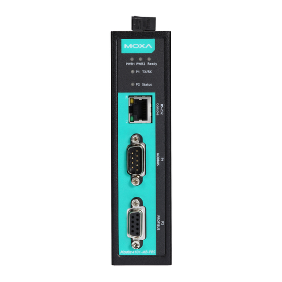
Шлюзы Field Bus серии MOXA MGate 4101-MB-PBS

Контактная информация службы технической поддержки: www.moxa.com/support
Обзор
MGateTM 4101-MB-PBS и 4101I-MB-PBS представляют собой 1-портовые подчиненные шлюзы Modbus для последовательного подключения к PROFIBUS, которые обеспечивают преобразование протокола для пользователей, которым необходимо подключить устройства Modbus к ПЛК Siemens.
Контрольный список пакетов
Перед установкой MGate 4101-MB-PBS или 4101I-MB-PBS убедитесь, что пакет содержит следующие элементы:
- 1 MGate 4101-MB-PBS или 4101I-MB-PBS Modbus для подчиненного шлюза PROFIBUS
- Кабель RJ45-DB9 (для использования с консолью)
- Руководство по быстрой установке (печатное)
- Гарантийный талон
Сообщите своему торговому представителю, если что-либо из вышеперечисленного отсутствует или повреждено.
Опции
- ВК-36-02: Комплект для настенного монтажа
- Адаптер Mini DB9F-to-TB: Переходник DB9 «мама» на клеммную колодку
ПРИМЕЧАНИЕ: Этот продукт предназначен для питания от указанного адаптера питания или источника питания постоянного тока с маркировкой «LPS» (или «Ограниченный источник питания»), номиналом от 12 до 48 В постоянного тока, минимум 275 мА, Tma = минимум 75°C.
Если вам нужна дополнительная помощь, пожалуйста, свяжитесь с MOXA Inc. для получения дополнительной информации.
Введение в аппаратное обеспечение
Светодиодные индикаторы
| LED | Цвет | Функция |
| PWR1 | Зелёная | Питание включено |
| от | Питание отключено | |
| PWR2 | Зелёная | Питание включено |
| от | Питание отключено | |
| Готовый | Зелёная | Шлюз работает |
| Red | Сбой проверки конфигурации или сбой установки параметра | |
| от | Питание отключено или существует неисправность | |
| P1 TX/RX (последовательный Modbus) | Зелёная | Последовательное устройство передает данные |
| Апельсин | Последовательное устройство получает данные | |
| от | Данные не передаются в последовательный порт или из него | |
| Статус P2 (PROFIBUS) | Зелёная | Горит постоянно: идет обмен данными |
| Red | Горит постоянно: скорость передачи определяется автоматически. Неправильный адрес подчиненного устройства или CHK_PRM или CHK_CFG будут постоянно гореть красным цветом. | |
| от | PROFIBUS в автономном режиме |
MGate 4101-MB-PBS и 4101I-MB-PBS поставляются с кабелем RJ45-DB9 для подключения к последовательной консоли.
кнопка сброса
Кнопка сброса используется для загрузки заводских настроек по умолчанию. Используйте заостренный предмет, например распрямленную скрепку, чтобы удерживать кнопку сброса нажатой в течение пяти секунд. Отпустите кнопку сброса, когда индикатор готовности перестанет мигать.
Pull-high, Pull-low и Terminator для RS-485
Снимите верхнюю крышку MGate 4101-MB-PBS, чтобы отрегулировать DIP-переключатели для резистора pull-high, pull-low и терминатора каждого последовательного порта.
| SW | 1 | 2 | 3 |
| Подтягивающий резистор | Подтягивающий резистор | терминатор | |
| ON | 1 кОм | 1 кОм | 120 Ом |
| OFF | 150 кОм* | 150 кОм* | — * |
*По умолчанию
Процедура установки оборудования
ШАГ 1:
Подключите адаптер питания. Убедитесь, что адаптер подключен к заземленной розетке. Подключите линию питания от 12 до 48 В постоянного тока к клеммной колодке серии MGate 4101-MB-PBS/4101I-MB-PBS или подключите источник питания на DIN-рейке к клемме устройства MGate 4101-MB-PBS/4101I-MB-PBS. блокировать.
ШАГ 2:
Используйте кабель PROFIBUS для подключения устройства к ПЛК PROFIBUS или другому ведущему устройству PROFIBUS.
ШАГ 3:
Подключите ваше устройство к последовательному порту устройства.
ШАГ 4:
Прикрепите устройство к DIN-рейке или стене. Серия MGate 4101-MB-PBS/4101I-MB-PBS предназначена для крепления на DIN-рейку или настенного монтажа. Для установки на DIN-рейку нажмите на пружину и правильно прикрепите ее к DIN-рейке, пока она не встанет на место со щелчком. Для настенного монтажа сначала установите комплект для настенного монтажа (дополнительный), а затем прикрутите устройство к стене.
Монтаж на стене или в шкафу

Для крепления MGate 4101-MB-PBS к стене требуются два винта. Головки винтов должны быть диаметром от 5 до 7 мм, стержни должны быть диаметром от 3 до 4 мм, а длина винтов должна быть более 10.5 мм.
На следующем рисунке показаны два варианта монтажа:
Информация об установке программного обеспечения
Чтобы установить MGate Manager, загрузите его с веб-сайта Moxa. webсайт http://www.moxa.com. Затем нажмите кнопку «Установка» и следуйте инструкциям на экране. Для получения более подробной информации о MGate Manager обратитесь к Руководству пользователя.
Назначение контактов
Последовательный порт Modbus (штекер DB9)

|
шпилька |
RS-232 | RS-422 /RS-485 (4 Вт) | RS-485 (2 Вт) |
| 1 | DCD | TxD-(А) |
– |
|
2 |
RXD | ТxД+(Б) | – |
| 3 | TXD | ПхД+(Б) |
Данные+(Б) |
|
4 |
DTR | RxD-(А) | Данные-(А) |
| 5 | GND | GND |
GND |
|
6 |
DSR | – | – |
| 7 | РТС | – |
– |
|
8 |
CTS | – | – |
| 9 | – | – |
– |
Последовательный порт PROFIBUS (гнездо DB9)

|
PIN-код |
Название сигнала |
| 1 |
– |
|
2 |
– |
| 3 |
ПРОФИБУС D+ |
|
4 |
РТС |
| 5 |
Общий сигнал |
|
6 |
5V |
| 7 |
– |
|
8 |
ПРОФИБУС D- |
| 9 |
– |
Распиновка входа питания и выхода реле

 |
V2 + | V2- |  |
V1 + | V1- | ||
| Экранированная земля | Вход питания постоянного тока 2 | Вход питания постоянного тока 2 | НЕТ | Общий | Северная Каролина | Вход питания постоянного тока 1 | Вход питания постоянного тока 1 |
Характеристики
| Требования к питанию | |
| Потребляемая мощность | 12 в 48 постоянного тока |
| потребляемая мощность | 275 мА (макс.) |
| Рабочая Температура | Стандартная модель: от 0 до 60°C (от 32 до 140°F) Широкая темп. Модель: от -40 до 75°C (от -40 до 167°F) |
| Влажность при эксплуатации | 5 в 95% RH |
| Габаритные размеры: | 36 х 105 х 140 мм (1.42 х 4.13 х 5.51 в) |
| Надежность | |
| Инструменты оповещения | Встроенный зуммер |
| MTBF | Серия MGate 4101-MB-PBS: 1,537,948 XNUMX XNUMX часов. Серия MGate 4101I-MB-PBS: 1,315,666 XNUMX XNUMX часов. |

- Сертификат ATEX №: DEMKO 14 ATEX 1311X
- Метод защиты: Ex nA nC IIC T4 Gc
- Сертификат IECEx №: IECEx UL 14.0065X
- Стандарты: EN 60079-0:2012+A11:2013; ЕН 60079-15:2010; МЭК 60079-0, издание 6; МЭК 60079-15 Ред.4.
- Условия безопасного использования:
• Это оборудование должно использоваться только в зоне со степенью загрязнения не выше 2, как определено в IEC/EN 60664-1.
• Это оборудование должно быть установлено в корпусе, обеспечивающем степень защиты не ниже IP54 в соответствии с IEC/EN 60079-15. Доступ к корпусу должен осуществляться только с помощью инструмента (гаечного ключа, отвертки и т. д.).
• Должна быть обеспечена защита от переходных процессов, установленная на уровне, не превышающем 140% пикового номинального объема.tagзначение e на клеммах питания оборудования. - Температура окружающей среды: -40°C Tокр. 75°C для моделей MGate 4101X-MB-PBS-T; 0°C Tокр. 60°C для моделей MGate 4101X-MB-PBS.
Значение крутящего момента клеммной колодки и калибр провода:
• Клеммная колодка (вилка соответствует розетке): рассчитана на 300 В, 15 А, 105°C, размер провода 12-28 AWG (от 0.0804 мм2 до 3.31 мм2), значение крутящего момента 4.5 фунт-дюйма (0.509 Нм). Размер кабеля входной клеммы: 14 AWG (2.1 мм²).
ВНИМАНИЕ
Эти устройства представляют собой устройства открытого типа, которые необходимо устанавливать в корпус, доступ к которому возможен только с помощью инструмента, подходящего для окружающей среды.
ПРИМЕЧАНИЕ: Это оборудование подходит для использования только в классах I, разделе 2, группах A, B, C и D или в безопасных зонах».
ПРЕДУПРЕЖДЕНИЕ
ОПАСНОСТЬ ВЗРЫВА. Не отсоединяйте оборудование, пока не будет отключено питание или известно, что зона не является взрывоопасной.
ПРЕДУПРЕЖДЕНИЕ
ОПАСНОСТЬ ВЗРЫВА. Замена любых компонентов может ухудшить пригодность для Класса I, Раздела 2.
Moxa Inc.
№ 1111, Heping Rd., Bade Dist., Taoyuan City 334004, Тайвань

Документы / Ресурсы
Рекомендации
Moxa Technologies MGate 4101-MB-PBS Gateway PDF User Guides and Manuals for Free Download: Found (6) Manuals for Moxa Technologies MGate 4101-MB-PBS Device Model (Quick Installation Manual, Operation & User’s Manual)
More Gateway Device Models:
-
bihl+Wiedemann
BWU3857
Subject to technical modifications; no responsibility is accepted for the accuracy of this information© Bihl+Wiedemann GmbH1Internet: www.bihl-wiedemann.de • Flosswoerthstr. 41 • D-68199 Mannheimphone: +49 621 33 996-0 • fax: +49 621 33 922 399Ausgabedatum: 05.02.2019 ASi-5/ASi-3 CIP Safety über EtherNet/IP + M …
BWU3857 Gateway, 40
-
Neptune
R900
Reading ModesFunction ExplanationNormal Normal Mode is used to connect through Bluetooth to a host device. Selection between Route (filtered) and RF Test (unfiltered) is made in the host device software.To enter this mode from other modes: 1 Press until the Mode LED flashes .2 Press , and the Mode LED turns .Unatten …
R900 Receiver, 2
-
Cisco
1700 series
Configuring a Cisco 1700/2600/3600 ADSL WIC toSupport PPPoE Clients, Terminating on a Cisco6400 UACDocument ID: 12963ContentsIntroduction Prerequisits Requirements Components Used Conventions Configure Network Diagram Configurations Verify Troubleshoot Related InformationIntroductionThe Cisco 1 …
1700 series Network Router, 5
-
EI
SmartLINK Ei1000G
1Ei1000GInstallation ManualSmartLINK GatewayRead and retain carefully for as long as the product is being used. It contains vital information on the operation and installation. The leaflet should be regarded as part of the product.If you are just installing the unit, the leaflet MUST be given to the householder. The le …
SmartLINK Ei1000G Gateway, 28
Recommended Documentation:
Page 1 — Slave Gateway User’s Manual
MGate-4101-MB-PBS Modbus Serial-to-PROFIBUS Slave Gateway User’s Manual First Edition, October 2011 www.moxa.com/product © 2011 Moxa Inc. All rights
Page 2
MGate 4101-MB-PBS UM Hardware 3-3 Orange Steady: Error in Configuration. Blinking: Error in Parameter data Off PROFIBUS offline or Slave ID wrong.
Page 3 — Table of Contents
MGate 4101-MB-PBS UM Hardware 3-4 6 5V 7 N.C. 8 PROFIBUS D- 9 N.C. Console (RS-232) Pin Assignment The MGate 4101-MB-PBS series use RJ45 serial
Page 4 — Introduction
MGate 4101-MB-PBS UM Hardware 3-5 Specifications Power Input Input Voltage 12 to 48 VDC Connector 8-pin terminal block (GND, V1+, V1-, R
Page 5 — Product Features
MGate 4101-MB-PBS UM Hardware 3-6 Warranty 5 years Adjustable Pull High/Low Resistors for the Modbus Port (P1) in RS-485 Mode SW 1 2 3
Page 6 — Getting Started
MGate 4101-MB-PBS UM Hardware 3-7 To reset the MGate to the factory default settings, hold down the reset button for about 5 seconds. The MGate will
Page 7 — Connecting PROFIBUS Devices
4 4. Configuration The following topics are covered in this chapter: Installing the Software Starting MGate Manager Connecting to the Unit
Page 8 — Hardware
MGate 4101-MB-PBS UM Configuration 4-2 Installing the Software The following instructions explain how to install MGate Manager, a utility for config
Page 9 — LED Indicators
MGate 4101-MB-PBS UM Configuration 4-3 3. When the Select Destination Location window appears, click Next to continue. You may change the destinati
Page 10 — Pin Assignments
MGate 4101-MB-PBS UM Configuration 4-4 5. Click Next to start copying the software files. 6. A progress bar will appear. The procedure should tak
Page 11 — Mounting the Unit
MGate 4101-MB-PBS UM Configuration 4-5 7. A message will indicate that MGate Manager is successfully installed. You may choose to run it immediatel
Page 12 — Specifications
MGate-4101-MB-PBS Modbus Serial-to-PROFIBUS Slave Gateway User’s Manual The software described in this manual is furnished under a license agreement a
Page 13 — Reset Button
MGate 4101-MB-PBS UM Configuration 4-6 Starting MGate Manager MGate Manager is a Windows-based utility that is used to configure the MGate 4101-MB-P
Page 14 — Rotary Switch
MGate 4101-MB-PBS UM Configuration 4-7 When you click OK, MGate Manager will immediately reflect your chosen language. After changing to a differen
Page 15 — Configuration
MGate 4101-MB-PBS UM Configuration 4-8 Specify by IP Address Specify by IP Address is used for MGate Ethernet Gateways, such as the MGate MB3000 and
Page 17
MGate 4101-MB-PBS UM Configuration 4-10 Modifying the Configuration Once your unit is displayed in MGate Manager, select it by clicking on it. The C
Page 18
MGate 4101-MB-PBS UM Configuration 4-11 Configure Device In first page, you can change device name and select a Password to protect the unit from un
Page 19
MGate 4101-MB-PBS UM Configuration 4-12 Configure Modbus Settings The Serial tab is where Modbus serial port’s communication parameters are configur
Page 20 — Starting MGate Manager
MGate 4101-MB-PBS UM Configuration 4-13 Max. Retry Master mode only, the number of times the master will retry the same request when response time
Page 21 — Connecting to the Unit
MGate 4101-MB-PBS UM Configuration 4-14 IO Mapping Setup In this page, you should define all commands that Modbus uses and all I/O modules PROFIBUS
Page 22 — Connect through COM Port
MGate 4101-MB-PBS UM Configuration 4-15 Each Modbus request includes Enable, Modbus slave ID, Function Code, Address, Length, Internal Address, Poll
Page 23
Table of Contents 1. Introduction …
Page 24 — Modifying the Configuration
MGate 4101-MB-PBS UM Configuration 4-16 After all Modbus requests finish, all the data collected from Modbus should be mapped to PROFIBUS I/O module
Page 25 — Configure Device
MGate 4101-MB-PBS UM Configuration 4-17 NOTE Each “ID” of the commands must be mapped, that is, the commands in Modbus will correspond with the I/O
Page 26 — Configure Modbus Settings
MGate 4101-MB-PBS UM Configuration 4-18 The interface of next dialog is divided into two sections. The upper section is labeled Modbus and will dis
Page 27 — Set up PROFIBUS
MGate 4101-MB-PBS UM Configuration 4-19 IO Map The IO Map is a mechanism which is applied when data from different networks are exchanged via the ga
Page 28 — IO Mapping Setup
MGate 4101-MB-PBS UM Configuration 4-20 In addition you can select the Paging checkbox to enable the page function, so the utility will insert two
Page 29
MGate 4101-MB-PBS UM Configuration 4-21 The IO map interface shows input and output memory array. The row unit is internal address and the column un
Page 30
MGate 4101-MB-PBS UM Configuration 4-22 Load Default If for some reason you would like to clear all the settings of the unit, the load default butto
Page 31 — QuickLink
MGate 4101-MB-PBS UM Configuration 4-23 Monitoring Modbus Activity For troubleshooting or management purposes, you can monitor the data passing thro
Page 32
MGate 4101-MB-PBS UM Configuration 4-24 Open Traffic Monitor Window Select the unit that you wish to monitor and click Monitor to open the Traffic
Page 33
MGate 4101-MB-PBS UM Configuration 4-25 To stop capturing the log, press the Stop button. Save Log to File To save the data log to a file, click
Page 34
1 1. Introduction Welcome to the MGate 4101-MB-PBS line of Modbus to PROFIBUS gateways. All models feature easy protocol conversion from Modbus to P
Page 35
MGate 4101-MB-PBS UM Configuration 4-26 Diagnose Diagnose is a powerful function to identify communications problems and assist in troubleshooting w
Page 36 — Load Default
MGate 4101-MB-PBS UM Configuration 4-27 There are two parts. In Modbus tab, the first part is the information regarding Modbus. These details will h
Page 37 — Monitoring Modbus Activity
MGate 4101-MB-PBS UM Configuration 4-28 Output The output bytes Input The input bytes Illegal I/O Config The number of illegal I/O configs Restar
Page 38
MGate 4101-MB-PBS UM Configuration 4-29 Once the firmware has been successfully written onto the unit, click Exit to close the Upgrade Firmware win
Page 39 — Save Log to File
MGate 4101-MB-PBS UM Configuration 4-30 If you export the configuration file successfully, a confirmation message will pop up. After that, the con
Page 40 — Diagnose
MGate 4101-MB-PBS UM Configuration 4-31 Please be patient and wait as MGate Manager configures the target device. If you import the configuration
Page 41
A A. Quick Configuration The following topics are covered in this appendix: Typical Applications Quick Configuration Steps PROFIBUS Overv
Page 42 — Upgrading Firmware
MGate 4101-MB-PBS UM Quick Configuration A-2 Typical Applications Here is a typical application to demonstrate how to use the Quick Link function an
Page 43 — Import/Export
MGate 4101-MB-PBS UM Quick Configuration A-3 Quick Configuration Steps MGate 4101-MB-PBS provides an innovative function which can automatically a
Page 44
MGate 4101-MB-PBS UM Quick Configuration A-4 Modbus Overview Introduction Modbus is one of the most popular automation protocols in the world. It s
Page 45
MGate 4101-MB-PBS UM Introduction 1-2 Overview The MGate 4101-MB-PBS is a line of protocol gateways that provides users with the following features:
Page 46 — Quick Configuration
MGate 4101-MB-PBS UM Quick Configuration A-5 Exception The master sends a request to the slave. The slave may not support the command or an error
Page 47 — Typical Applications
MGate 4101-MB-PBS UM Quick Configuration A-6 Integrate Modbus Serial and Ethernet with Gateways 7 Ordinarily, Modbus TCP and Modbus ASCII/RTU are un
Page 48 — PROFIBUS Overview
2 2. Getting Started The following topics are covered in this chapter: Connecting Power Connecting PROFIBUS Devices Connecting Modbus Seria
Page 49 — Modbus Overview
MGate 4101-MB-PBS UM Getting Started 2-2 Connecting Power The unit can be powered using the AC adaptor or by connecting a power source to the termin
Page 50 — Response Timeout
3 3. Hardware The following topics are covered in this chapter: Function Block Power Input and Relay Output Pinouts LED Indicators Dimen
Page 51 — Diagnose Packet Format
MGate 4101-MB-PBS UM Hardware 3-2 Function Block Power Input and Relay Output Pinouts V2+ V2- V1+ V1- Shielded Ground DC Power Input 2 DC