Русский
Указатель
1 Порядок работы
2 Структура меню
148
149
3 Назначение контактов клеммных колодок (TB) 150
4 Пример схемы подключения pHтрансмиттера 153
5 Общая настройка
(применима для всех параметров)
6 Калибровка pH включая ISFET
154
155
7 Калибровка датчиков O
2
157
8 Калибровка датчика CO
2
(InPro 5000) 158
9 Калибровка датчика CO
2
Hi (высокая)
(InPro 5500 i) 160
10 M400 тип 1 только Cond Ind: Калибровка электропроводности для индуктивных датчиков 162
11 Быстрая настройка датчиков электропроводности
12 Калибровка электропроводности
2 и 4электродных датчиков
13 TDL GPro™ 500
164
164
166
147
1 Порядок работы
Ввод значений и выбор вариантов установки параметров
Для изменения цифры в позиции редактирования используйте клавиши со стрелка ми вверх m
и вниз
.
. Эти же клавиши используются для выбора вариантов установ ки параметров.
h
Примечание.
На некоторых страницах меню в одном и том же поле ввода необходимо установить значения нескольких параметров (например, при конфигурировании нескольких точек установки). В таких случаях после установки значения параметра следует вернуться в основное поле ввода с помощью клавиши со стрелкой вправо c
или влево b
и выбрать следующий параметр с помощью клавиши со стрелкой вверх страницу. m
или вниз
.
, прежде чем перейти на следующую
Навигация со значком
u
на экране
Если справа в нижней части экрана отображается значок u , его можно выбрать с помощью клавиши со стрелкой влево c
или вправо b
. После этого, нажав клавишу
[ENTER], можно вернуться на предыдущий уровень меню (на предыдущую страни цу). Эту функцию удобно использовать для перемещения вверх по дереву меню, т.к. она позволяет сделать это без возврата в режим измерения и повторного вызова меню.
Выход из меню
h
Примечание.
Для выхода из меню в любое время нужно одновременно нажать клавиши со стрелками влево b режим измерения.
и вправо c
(ESCAPE). Трансмиттер вернется в
Диалоговое окно SAVE CHANGES (Сохранение изменений)
Диалоговое окно Save changes позволяет выбрать один из трех вариантов сохране ния:
– Yes & Exit (Да с выходом):
Сохраняет изменения и переходит в режим измерения.
– Yes & u (Да с возвратом на предыдущий уровень):
Сохраняет изменения и возвращается на предыдущий уровень меню.
– No & Exit (Нет с выходом):
Не сохраняет изменения и переходит в режим измерения.
Вариант Yes & u позволяет продолжить редактирование параметров без необходи мости повторного вызова меню.
148
2 Структура меню
Ìåíþ
Ñîîáùåíèÿ
Èçìåðåíèå
Ðåæèì M400
Êàëèáðîâêà
Äàííûå
êàëèáðîâêè
ÈÍÔÎ
Ïðîâåðêà
ìîäåëè/ÏÎ
Èíô. äàò÷èêà ISM* Äèàãíîñòèêà ISM*
Áûñòðàÿ
óñòàíîâêà**
Íà÷àëî ðàáîòû Ñèñòåìà
Íàñòðîéêà
ÏÈÄ-ðåãóëÿò.
Îáñëóæèâàíèå
Êàíàë Âûáîð
âûõîäû
Çàäàòü òî÷êè
Èçìåðåíèå
Àíàëîãîâûå
âûõîäû
Çàäàòü òî÷êè
Ñèãíàë/Ñáðîñ
Äèñïëåé
Çàïîìíèòü
âûõîäû
Íàñòðîéêà ISM*
Çàäàòü ÿçûê
USB
Ïàðîëè
Óñò./ñáðîñ
áëîêèðîâêè
Ñáðîñ
Äèñïëåé ÏÈÄ
ÏÈÄ/AM
Ïàðàìåòðû
ðåãóëèðîâêè
Ðåæèì
* Äîñòóïíî òîëüêî â ñî÷åòàíèè ñ äàò÷èêàìè ISM.
** Íå èñïîëüçóéòå ïîñëå íàñòðîéêè
Äèàãíîñòèêà
Êàëèáðîâêà
Òåõí.
Îáñëóæèâàíèå
149
3 Назначение контактов клеммных колодок (TB)
Подключения цепи питания маркируются следующим образом:
– N
нейтральный провод,
+L
фазный провод, переменное напряжение 100 – 240 В или постоянное напряжение 20 – 30 В.
TB2 для версии
1 AO1+
2 AO1– / A
3 A
O2
+
O2
8 DI1– / DI2–
9 DI2+
–
4 AO3+
5 AO3– / AO4–
6 AO4+
7 DI1+
2
TB1 1 14
1 9 1 9 1 9
TB2 TB3 TB4
Внимание:
это 4х проводная версия с аналого выми выходами
4–20 мА.
Пожалуйста, не используйте для подключения разъ емы 1–6 клеммной колодки ТВ2.
TB1 для версии
1 NO1
2 COM1
3 NC1
4 N O2
5 COM2
6 NC2
7 COM5
2
8 NC5
9 COM6
10 NO6
11 NO3
12 COM3
13 NO4
14 COM4
NO =
замыкаю щий контакт
(нормально открытый).
NC =
размыкаю щий контакт
(нормально замкнутый).
TB4 – Датчики ISM (цифровые)
6
7
8
9
4
5
Контакт
Функция
1
2
3 пост. напряжение 24 В однопровод. схема
TDL GPro™
500
Оптический датчик кислорода,
InPro 5500 i (CO
2
)
Цвет
–
Зазем. (пост. напр. 24 В) –
–
Зазем. (пост. напр. 5 В) –
–
–
Цвет
коричневый черный
–
Зазем. (пост. напр. 5 В) коричневый –
RS485B желтый синий
RS485A пост. напр. 5 В зеленый
– зеленый/желтый
– белый
–
InPro 6860 i
(кабель VP8)
Цвет
серый синий
–
pH, амперометрический датчик кислорода, проводимости
4-проводной,
InPro 5000 i
Цвет
–
–
Прозрачный
(жила кабеля) зеленый/желтый Красный (экран)
– –
– коричневый розовый
–
–
–
–
–
150
TB3 – Общеупотребительные датчики (аналоговые)
Cond 2-E или 4-E
Контакт Функция
1
8
9
6
7
4
5
2
3
Электропроводность, внутр.1
Электропроводность, внешн.1
–
Терм. сопр., общ. / зазем.
Цвет*
белый белый / синий
Электропроводность, внутр.2
Электропроводность, внешн. 2 / Экран черный
Терм. сопр., измерит.
Терм. сопр.
+5 В синий
– красный зеленый
–
Амперометрический датчик кислорода
Функция
–
Анод
–
Экран / зазем. зеленый/желтый
Катод неизол. оплетка GND / NTC
–
NTC
+5 В
Цвет
– красный
– прозрачный зеленый
– белый
–
Клеммы 4 и 6 соединены. Для подключения провода можно использовать лю бую клемму.
* Прозрачный не используется.
TB3 – Общеупотребительные датчики (аналоговые) pH
Контакт Функция
3
4
1
2
Стекло
–
Электрод сравн.**
Электрод зазем. раств. / Экран**
Цвет*
прозрачный
– красный зеленый / желтый и синий
ОВП
Функция
Платина
–
Цвет
прозрачный***
–
Электрод сравн. Экран
– –
7
8
5
6
9
– –
Терм. сопр., общ. / зазем. белый
Терм. сопр., измерит.
Терм. сопр.
+5 В
– зеленый
–
–
–
–
–
–
–
–
–
–
–
Клеммы 4 и 6 соедине ны. Для подключения провода можно исполь зовать любую клемму.
* Серый провод не используется.
** Для измерения pH без заземления рас твора необходимо установить перемыч ку между 3 и 4.
*** удалить черное покрытие.
TB3 – Общеупотребительные датчики (аналоговые)
7
8
5
6
9
3
4
1
2
Cond Ind
Контакт Цвет. InPro 7250 ST / PFA
Коакс. внутр. / прозрачный Коакс. внутр. / прозрачный прием hi красный зеленый / желтый корич., белый синий белый серый зеленый
–
Цвет. InPro 7250 HT
желтый зеленый / желтый фиолет.
черный белый серый зеленый
–
Функция
прием lo
Экран / зазем.
отправка lo отправка hi
Терм. сопр., общ. / зазем.
Терм. сопр., измерит.
Терм. сопр.
Не используется
Клеммы 4 и 6 соедине ны. Для подключения провода можно исполь зовать любую клемму.
151
TB3 – Общеупотребительные датчики (аналоговые)
Контакт Цвет*
1
2
3** Коакс. экран. / красный
4**
5
6
7
8
9
Датчик растворенного углекислого газа
– зеленый / желтый
– белый
– зеленый
–
Функция
Коакс. внутр. / прозрачный Стекло
Не используется
Электрод сравн.
Экран / зазем.
Не используется
Терм. сопр., общ. / зазем.
Не используется
Терм. сопр.
+5 В
Клеммы 4 и 6 соединены.
Для подключения прово да можно использовать любую клемму.
* Серый провод не используется.
** необходимо устано вить перемычку между
3 и 4.
TB3 – Общеупотребительные датчики (аналоговые)
ISFET
Контакт Цвет
1 Коакс. внутр. / розовый
Функция
FET
2
3*
4*
5
6
7
8
9
– желтый зеленый / желтый
– белый
– серый коричневый
Не используется
Электрод сравн.
Экран / зазем.
Не используется
Терм. сопр., общ. / зазем.
Не используется
Терм. сопр.
+5 В
Клеммы 4 и 6 соединены.
Для подключения прово да можно использовать любую клемму.
* необходимо установить перемычку между 3 и 4.
152
4 Пример схемы подключения pH-трансмиттера
(с использованием TB3)
Измерение pH с контролем стеклянного электрода.
SG (çàçåìëåíèå
÷åðåç ðàñòâîð)
9
8
7
6
5
2
1
4
3
Ïåðåìû÷êà åñëè pH-ýëåêòðîä áåç SG
9
8
7
6
5
4
3
2
+5 Â
RTD (Òåðì. ñîïð.)
Òåðì. ñîïð., èçìåðèò.
Òåðì. ñîïð. îáð./Çàçåì.
Íå èñïîëüçóåòñÿ
Çàçåì. ðàñòâ./Ýêðàí
Îïîðíûé ñèãíàë
Íå èñïîëüçóåòñÿ
1 Ñòåêëî
Êàáåëü
Äàò÷èê
òåìïåðàòóðû
Êîìáèíèðîâàííûé pH-ýëåêòðîä ñ RTD è SG h
Примечание.
Цветовая кодировка проводников указана для кабеля VP; серый провод не подключается.
153
5 Общая настройка
(применима для всех параметров) (путь: Меню / Начало работы)
21.7
25.0
Меню
Начало работы
%sat
°C
В режиме измерения нажмите клавишу [MENU], чтобы вызвать на экран меню.
Выберите ”Начало работы” и нажмите клавишу [ENTER].
Обозначение строк экрана:
Первая строка на экране
Вторая строка на экране
→
a
b
Третья строка на экране
Четвертая строка на экране
→
c
d
Выберите единицы измерения для ”a” и ”b”. В режиме быстрой настройки для кон фигурирования доступны только строки ”a” и ”b”. Конфигурирование строк ”c” и ”d” выполняется в меню Configuration.
Выбор канала
A
A
6.0
25.0
Канал Выбор = ISM
Параметр = Авто
pH
°C
Выберите тип датчика:
Аналоговый: Для большинства аналоговых датчиков
ISM:
(будут отображаться на канале А).
Для датчиков ISM (будут отображаться на канале В).
Выберите критерий параметра:
Выбор параметра зависит от уровня трансмиттера. Если выбран датчик ISM, зна чение ”Auto” будет означать, что будут распознаваться и приниматься все возмож ные датчики ISM. Если выбран специальный параметр, распознаваться и прини маться трансмиттером будет только этот параметр.
Для аналоговых 2- и 4-электродных датчиков электропроводности см. раздел ”Быстрая настройка датчиков электропроводности”, приведенный ниже.
Аналоговые выходы
pH
7.0
25.0
°C
Aout1 мин. = 0.000 pH
Aout1 макс = 14.00 pH u
Для того чтобы привязать линейный аналоговый выход 4–20 мА (Aout1) к измеряе мой переменной и настроить его параметры, выберите Yes и нажмите клавишу
[ENTER]. Для того чтобы отказаться от настройки параметров аналоговых выходов, выберите No.
Параметры Aout1 min и Aout1 max определяют минимальное и максимальное зна чения измеряемой величины, соответствующие границам шкалы выходного тока 4 и 20 мА.
h
Примечание для многоканальных устройств.
Можно настроить выход A out 3 на измерение ”c”, вернувшись в предыдущее меню и выбрав ”c”.
154
Уставки
7.0
pH
25.0
a Задать точку Да
З.Т.1 Тип = откл.
°C u
После настройки аналогового выхода можно задать параметры уставки для данно го выхода. Если выбрать No и нажать клавишу [ENTER], трансмиттер выйдет из режима быстрой настройки без задания параметров уставки.
7.0
pH
25.0
°C
З.Т.1 междуH = 0.000
З.Т.1 междуL = 0.000 u
7.0
25.0
pH
°C
З.Т.1 Исп. Реле # 1 u
Выбор YES и нажатие клавиши [ENTER] означает, что для канала a была настроена уставка.
Можно выбрать один из следующих типов уставки:
– High (верхняя граница, необходимо задать значение параметра High)
– Low (нижняя граница, необходимо задать значение параметра Low)
– Between (внутри границ, необходимо задать значения параметров High и Low)
– Outside (вне границ, необходимо задать значения параметров High и Low)
После установки значения уставки (уставок) можно настроить реле (Relay) сигна лизации для этой уставки (возможные варианты: none – реле не используется, 1, 2,
3, 4). Для задержки срабатывания реле и гистерезиса по умолчанию установлены значения 10 сек и 5% соответственно. Если реле настроено как реле CLEAN (реле очистки), оно не доступно из этого меню.
Для многоканальных устройств:
в этом случае можно также настроить уставки
5 и 6, при этом можно настроить уставку на измерение ”c”, вернувшись в предыду щее меню и выбрав ”c”.
6 Калибровка pH включая ISFET
(путь: Калибровка)
Настройка экрана, аналоговых выходов и уставок приведена в разделе ”Общая настройка”.
Калибровка датчика pH (соотв. ISFET) по двум точкам
Примечание. При использовании датчиков ISFET сначала необходимо произвести регулировку нулевой точки.
A
A
7.0
25.0
MΩ-cm
Калибровать датчик
°C
Канал A pH m
В режиме измерения нажмите клавишу со стрелкой вправо c
. Если на экране поя вится запрос на ввод пароля для калибровки, нажмите клавишу со стрелкой вверх m
или вниз
.
для задания пароля, а затем нажмите клавишу [ENTER] для под тверждения ввода.
Нажмите клавишу со стрелкой вверх m
или вниз
.
для выбора функции калибровки датчиков pH (соотв. ISFET).
Мигающий символ ”H” выполняет роль индикатора выполнения процесса калибров ки.
155
H
7.0
pH
25.0
Калибровка pH
Тип = 2 точки
°C
H
7.0
pH
25.0
Датчик в буфере 1
°C
Нажмите ENTER, если
H
7.0
pH
25.0
Датчик в буфере 2
°C
Нажмите ENTER, если u u u
Выберите (2 point) калибровку подвум точкам и нажмите клавишу [ENTER].
Погрузите электрод в первый буферный раствор и нажмите клавишу [ENTER].
После того как значения стабилизируются (или будут введены в ручном режиме нажатием клавиши ”Ввод”), на дисплее появится предложение поместить электрод во второй буфферный раствор.
H
7.0
pH
25.0
Точка 2 = 6.86 pH
pH = 7.00 pH
°C u
После того как значения стабилизируются (или будут введены в ручном режиме нажатием клавиши ”Ввод”), на дисплее отобразится значения калибровки – наклон и нулевая точка. Выберите Adjust (Добавить), чтобы сохранить новые данные кали бровки; на экране появится подтверждение успешной калибровки (Successful
Calibration). Если выбрать calibrate (калибровка), значения не будут учитываться.
Если используется датчик ISM, данные калибровки будут сохранены в журнале про ведения калибровок.
Калибровка по технологической среде
H
7.0
25.0
Калибровка pH
Тип = Процесс
pH
°C u
Выберите калибровку по технологической среде (Process) и нажмите клавишу m бровки в левом верхнем углу экрана отображается символ ”H”.
, а потом сразу же клавишу [ENTER]. Для индикации незавершенного процесса кали
A
7.0
pH
25.0
Точка 1 = 7.00 pH
pH = 6.87 pH
°C u
Символ ”H” изменяется на символ ”A” (или ”B”, в зависимости от типа датчика), если выбрана калибровка по технологической среде, что выполняет функцию индикато ра выполнения процесса калибровки для канала ”А” или ”B”.
Выполните отбор пробы и нажмите клавишу [ENTER], чтобы сохранить в памяти текущее измеряемое значение.
После определения величины pH пробы нажмите клавишу со стрелкой вправо c
, чтобы продолжить процедуру калибровки. Если на экране появится запрос на ввод пароля для калибровки, нажмите клавишу или для задания пароля, m
а
.
затем нажмите клавишу [ENTER] для подтверждения ввода.
156
A
7.0
pH
25.0
°C pH S = 100.0 % Z = 7.124
Сохр. калибровку? Да u
Введите значение pH образца и нажмите клавишу [ENTER].
После завершения калибровки на экран выводятся значение наклона калибровоч ной характеристики S и величина сдвига калибровочной характеристики Z. Выбери те Adjust, чтобы сохранить новые данные калибровки; на экране появится под тверждение успешной калибровки (Successful Calibration). Если выбрать calibrate
(калибровка), значения не будут учитываться. Если используется датчик ISM, дан ные калибровки будут сохранены в журнале проведения калибровок. После этого индикатор ”A” в левом верхнем углу экрана погаснет.
7 Калибровка датчиков O
2
(путь: Калибровка)
Настройка экрана, аналоговых выходов и уставок приведена в разделе ”Общая настройка”.
Калибровка датчиков O
2
A
A
21.7
25.0
Калибровать датчик
Канал B Кислород
pH
°C m
Для многоканальных устройств:
при помощи клавиш m
и
.
в поле Channel A мож но изменить канал, выбранный для калибровки.
Для переключения в режим калибровки нажмите клавишу c
.
В верхнем левом углу экрана отображается мигающий символ ”H” (перемежающий ся с символом ”A” или ”B”, определяющим какой из каналов будет калиброваться, в случае работы с многоканальным устройством), который выполняет функцию инди катора выполнения процесса калибровки.
H
21.7
25.0
%sat
°C
Точка 1 = 100.0 %sat
DO = 0.033 %sat u
Для датчиков растворенного кислорода всегда используется одноточечная кали бровка наклона характеристики в воздухе (Slope) или калибровка нуля характери стики (Offset).
Выберите тип калибровки (Slope или Zero). Калибровка по одной точке наклона ха рактеристики выполняется в воздухе, а одноточечная калибровка смещения – в среде с нулевым содержанием растворенного кислорода. После выбора калибров ки Slope или Offset нажмите клавишу [ENTER].
H
21.7
25.0
%sat
°C
O2 S = 0.019nA Z = 0.000nA
Сохр. калибровку? Да u
Введите значение, соответствующее калибровочной точке 1, включая десятичную точку. DO это значение, измеренное трансмиттером и датчиком в текущих вы бранных пользователем единицах измерения. После установления этого значения нажмите клавишу [ENTER], чтобы выполнить калибровку. – После завершения ка либровки на экран выводятся значение наклона калибровочной характеристики S и величина сдвига калибровочной характеристики Z.
157
H
21.7
25.0
Калибр. провед.
Успешно
%sat
°C
Выберите Adjust, чтобы сохранить данные калибровки; на экране появится под тверждение успешной калибровки (Successful Calibration). Если выбрать calibrate
(калибровка), значения не будут учитываться. Если используется датчик ISM, дан ные калибровки будут сохранены в журнале проведения калибровок.
8 Калибровка датчика CO
2
(InPro 5000)
(путь: Калибровка)
Настройка экрана, аналоговых выходов и уставок приведена в разделе ”Общая настройка”.
Калибровка датчика CO
2
A
A
180.4
26.1
hPa
Калибровать датчик
°C
Канал A CO2 u
по одной точке
В режиме измерения нажмите клавишу [CAL]. Нажмите клавишу m
или
.
для выбора Калибровка датчика CO
2 подфункции.
и нажмите клавишу [ENTER] для вызова
Выберите точку 1 и нажмите [ENTER].
H
180.4
hPa
A
26.1
Калибровка CO2
Тип = 1 точка
°C u
H
A
137.5
26.1
Нажмите ENTER, если
Датчик в буфере 1
hPa
°C u
Поместите датчик в буферный раствор и нажмите [ENTER], чтобы начать калибров ку.
На экране отображается буфер, распознанный трансмиттером (Point 1), и факти ческое измеренное значение.
154.5
26.1
hPa
A
A Точка1 = 7.00 pH
A CO2 = 7.07 pH
°C u
H
154.5
26.1
hPa
A
Сохр. настройки
°C pH S = 100.0% Z = 7.048pH
u
Сразу после стабилизации дрейфа параметров дисплей переключится на отобра жение наклона калибровочной характеристики S и сдвига калибровочной характе ристики Z.
После успешного выполнения калибровки калибровочные значения можно принять
(Adjust) или отменить (Calibrate или Abort).
158
CO
2
по двум точкам
Начало по аналогии с калибровкой датчика CO
A
A
154.5
26.1
Калибровка CO2
Тип = 2 точка
hPa
°C u
2
по одной точке.
Выберите калибровку по 2 точкам.
H
A
137.5
26.1
Нажмите ENTER, если
Датчик в буфере 1
hPa
°C u
Поместите датчик в первый буферный раствор и нажмите [ENTER], чтобы начать
калибровку.
154.5
26.1
hPa
A
A Точка1 = 7.00 pH
A CO2 = 7.07 pH
°C
122.4
26.1
hPa
A
Датчик в буфере 2
°C
Нажмите ENTER, если
2.8
26.1
hPa
A
A CO2 = 8.80 pH
°C
A Точка2 = 9.21 pH . . .
2.8
26.1
hPa
A
Сохр. настройки
°C pH S = 74.21% Z = 6.948pH
u u u u
На экране отображается буфер, распознанный трансмиттером (Point 1), и факти ческое измеренное значение.
Сразу после стабилизации параметров на дисплей будет выведено предложение поместить электрод во второй буфер.
Поместите датчик во второй буферный раствор и нажмите [ENTER], чтобы продол жить калибровку.
На экране отображается второй буфер, распознанный трансмиттером (Point 2), и фактическое измеренное значение.
Сразу после стабилизации дрейфа параметров дисплей переключится на отобра жение наклона калибровочной характеристики S и сдвига калибровочной характе ристики Z.
После успешного выполнения калибровки калибровочные значения можно принять
(Adjust) или отменить (Calibrate или Abort).
159
CO
2
по технологической среде
Начало по аналогии с калибровкой датчика CO
A
A
17.3
27.3
Калибровка CO2
Тип = Процесс
hPa
°C u
2
по одной точке.
Калибровка по технологической среде.
A
17.3
27.3
hPa
A
°C
A Точка1 = 00000 hPa
A CO2 = 17.3 hPa
A
17.3
27.3
hPa
A
°C
A Точка1 = 16.90 hPa
A CO2 = 17.3 hPa u u
Выполните отбор пробы и нажмите клавишу [ENTER], чтобы сохранить в памяти текущее измеряемое значение. Для отображения выполняющегося технологическо го процесса на дисплее мигает A или B (в зависимости от канала). После определе ния величины CO калибровки.
2
пробы снова нажмите клавишу c
, чтобы продолжить процедуру
Введите значение CO
2 бровку.
образца и нажмите клавишу [ENTER], чтобы начать кали
A
17.3
27.3
hPa
A
Сохр. настройки
°C pH S = 100.0% Z = 7.009pH
u
На дисплей будет выведено значение наклона калибровочной характеристики S и величина сдвига калибровочной характеристики Z.
После успешного выполнения калибровки калибровочные значения можно принять
(Adjust) или отменить (Calibrate или Abort).
9 Калибровка датчика CO
2
Hi (высокая) (InPro 5500 i)
(путь: Калибровка)
Настройка экрана, аналоговых выходов и уставок приведена в разделе ”Общая настройка”.
Калибровка по одной точке
B
B
189.0
25.0
hPa
Калибровать датчик
°C
Канала B CO2 Hi u
В режиме измерения нажмите клавишу [CAL]. Нажмите клавишу
.
или m
для выбора калибровки датчика CO подфункции.
2
Hi и нажмите клавишу [ENTER] для вызова
160
B
189.0
hPa
H
25.0
CO2 Hi Калибровка
Тип = 1 точка
°C u
B
189.0
25.0
hPa
H
°C
Нажмите ENTER, если датчик в среде (CO2) u
Выберите ”1 точка” и нажмите [ENTER].
Поместите датчик в соответствующий раствор калибровочного газа
(например, 100% CO
Нажмите [ENTER].
2
).
B
B
H
189.0
25.0
189.0
25.0
CO2 S=
9.28
mV BL=
Сохр. настройки
hPa
H
B CO2=189.0 hPa
°C
B Точка1=1013. hPa .
hPa
°C
253
mV u u
Введите значение, соответствующее калибровочной точке 1, включая десятичную точку и единицу измерения. Значение во второй строке текста — это значение, измеренное трансмиттером и датчиком в текущих выбранных пользователем единицах измерения.
В зависимости от параметров управления дрейфом (см. разд. 8.2.3.10
”Параметры CO
2
(Hi)”), активируется один из двух следующих режимов.
Если включено автоматическое управление дрейфом, то как только будет выполнен критерий стабилизации сигнала, трансмиттер автоматически выведет на дисплей результат калибровки.
Если включено ручное управление дрейфом, то как только значение стабилизи руется, нажмите [ENTER], после чего трансмиттер выведет на дисплей результат калибровки.
При выборе опции ”Принято” или ”Калибровка” выводится сообщение ”Калибр. провед. успешно”. В любом случае на дисплей будут выведены сообщения ”За менить датчик” и ”Нажмите ENTER”. После нажатия [ENTER] трансмиттер M400 возвращается в режим измерений.
Калибровка по технологической среде
Начните процедуру, как описано в разделе ”Калибровка по одной точке”.
B
H
189.0
25.0
CO2 Hi
Калибровка
Тип = Процесс
hPa
°C u
Выберите ”Калибровка по технологической среде”.
161
B
189.0
25.0
hPa
B
B CO2=189.0 hPa
°C
Press ENTER to Capture u
B
189.0
25.0
hPa
H
°C
B Точка1=1013. hPa
B CO2=189.0 hPa u
B
189.0
25.0
hPa
H
CO2 S=
9.28
°C
mV BL=
253
mV
Сохр. настройки u
Отберите пробу и вновь нажмите клавишу [ENTER], чтобы сохранить в памяти текущее измеряемое значение Выполнение процесса калибровки сопровожда ется мигающими символами A или B на дисплее (в зависимости от канала).
После определения значения содержания CO
2
в пробе технологической среды вновь нажмите клавишу [CAL], чтобы продолжить калибровку.
Введите значение CO
2
для пробы и нажмите клавишу [ENTER], чтобы начать вычисление результатов калибровки.
После завершения калибровки на экран выводится значение наклона калибро вочной характеристики S и величина сдвига калибровочной характеристики Z.
При успешном завершении калибровки данные калибровки можно принять и сохранить в журнале калибровок (Принято), только сохранить в журнале кали бровок (Калибровка) или сбросить (Прервано).
При выборе опции ”Принято” или ”Калибровка” выводится сообщение ”Калибр. провед. успешно”. Трансмиттер M400 возвращается в режим измерений.
10 M400 тип 1 только Cond Ind: Калибровка электропроводности для индуктивных датчиков
(Путь: Cal – калибровка)
Настройка экрана, аналоговых выходов и уставок приведена в разделе ”Общая настройка”.
Калибровка нулевой точки Cond Ind
A
A
1.25
25.00
µS/cm
Калибровать датчик
°C
Канал A Эл.проводн. m
В режиме измерения нажмите клавишу [CAL]. Нажмите клавишу m
или
.
для вы бора калибровки датчика электропроводности. Затем нажмите [ENTER] для пере хода к функции.
A
A
Компенсация калибровки
Стандарт
1.25
25.00
µS/cm
°C m
Выберите способ калибровки (стандартная, линейная или по воде).
162
H
A
40.5
23.9
Калибровка эл.проводн.
Тип = нулевая точка mS/cm
°C u
A
A
1.035
21.9
A Точка 1 = 0.000 mS/cm mS/cm
°C
A C = 1.035 mS/cm u
Выберите нулевую точку и нажмите [ENTER]. Извлеките датчик и просушите его.
Еще раз нажмите [ENTER] для продолжения калибровки.
После установления показаний (или нажатия клавиши [ENTER] в ручном режиме) на экран выводятся значения множителя и слагаемого.
После окончания процесса калибровки данные калибровки можно принять и со хранить в журнале калибровок (Adjust), только сохранить в журнале калибровок
(Calibrate) или отменить калибровку (Abort).
Одноточечная калибровка наклона характеристики Cond Ind
Запустите калибровку, как описано в разделе ”Калибровка нулевой точки Cond Ind”.
Выберите способ калибровки.
A
217.4
25.0
Калибровка эл.проводн.
Тип = 1 точка Наклон
µS/cm
°C u
Выберите точку 1 на характеристике и нажмите [ENTER].
A
217.4
25.0
A Точка 1 = 215.0 µS/cm
A C = 217.4 µS/cm
µS/cm
°C u
Введите значение в точке 1 и нажмите клавишу [ENTER] для запуска калибровки.
На экран выводятся значения множителя и слагаемого. После окончания процесса калибровки данные калибровки можно принять и сохранить в журнале калибровок
(Adjust), только сохранить в журнале калибровок (Calibrate) или отменить калибров ку (Abort).
163
11 Быстрая настройка датчиков электропроводности
(путь: Меню / Начало работы)
Настройка экрана, аналоговых выходов и уставок приведена в разделе ”Общая настройка”.
Выбор типа датчика (Sensor Type)
1.25
25.0
°C
Тип датчика = эл.пр.(2)
µS/cm m
Выберите тип датчика, который будет использоваться для работы с трансмиттером
M400. Возможные варианты выбора: Cond(2), используемый для всех двухэлек тродных датчиков электропроводности, и Cond (4), используемый для всех четыре хэлектродных датчиков. Нажмите клавишу [ENTER].
Константа ячейки
1.25
25.0
µS/cm
°C p M = 0.1003 A = 0.0000
s M = 1.0000 A = 0.0000
Единицы измерения
1.25
25.0
°C a S/cm
Аналоговый выход? Да
µS/cm m
Введите подходящую константу ячейки: калибровочную постоянную (M), указан ную на паспортной табличке датчика или в его сертификате, оставив постоянную
(A) равной 0,000 для двухэлектродных датчиков; или постоянные (M) и (A) для четырехэлектродных датчиков. Нажмите клавишу [ENTER].
Выберите тип измерения (измерение электропроводности или температуры) и задайте единицы измерения. В случае использования аналогового выхода выбе рите Yes. Вернитесь к разделу ”Общая настройка”, чтобы продолжить процесс настройки.
12 Калибровка электропроводности 2- и 4-электродных датчиков
(путь: Cal)
Настройка экрана, аналоговых выходов и уставок приведена в разделе ”Общая настройка”.
Калибровка датчика электропроводности по одной точке
A
A
1.25
25.0
µS/cm
Калибровать датчик
°C
Канал A Эл.проводн. m
В режиме измерения нажмите клавишу со стрелкой вправо [CAL]. Если на экране появится запрос на ввод пароля для калибровки, нажмите клавишу со стрелкой вверх m
или вниз
.
для задания пароля, а затем нажмите клавишу [ENTER] для подтверждения ввода.
Нажмите клавишу [ENTER] для выбора функции калибровки датчиков электропро водности.
В верхнем левом углу экрана отображается мигающий символ ”H” (перемежающий ся с символом ”A” или ”B”, определяющим какой из каналов будет калиброваться, в случае работы с многоканальным устройством), который выполняет функцию инди катора выполнения процесса калибровки.
164
1.25
Стандарт
25.0
µS/cm
°C
Компенсация калибровки m
1.25
25.0
Тип = 1 точка
µS/cm
°C
Калибровка эл.проводн m
Выберите режим компенсации с помощью клавиш m
или
.
.
Для подтверждения выбора режима компенсации нажмите клавишу [ENTER].
Выберите калибровку по 1 точке вместо калибровки по 2 точкам, нажав один раз клавишу
.
, а потом клавишу [ENTER].
h
ВНИМАНИЕ!
Перед каждой калибровкой промывайте датчики водным раствором высокой очистки для предотвращения загрязнения стандартных растворов.
1.25
25.0
µS/cm
°C
A Точка1 = 0.055 µS/cm
A C = 0.057 µS/cm m
1.25
25.0
µS/cm
°C
C M = 0.1000 A = 0.0000
Сохр. калибровку? Да m
Поместите электрод в стандартный раствор.
Введите значение Точки 1 и нажмите клавишу [ENTER].
После завершения калибровки ячейки на экран выводятся значение множителя или наклона калибровочной характеристики ”M”, т.е. константа ячейки, и значение сла гаемого или сдвига калибровочной характеристики ”A”.
Выберите ”Yes”, чтобы сохранить новые данные калибровки; на экране появится подтверждение успешной калибровки (Successful Calibration).
На экран для пользователя будет выведено сообщение ”Reinstall sensor” (Переуста новите датчик) и ”Press [ENTER]” (Нажмите [ENTER]). После нажатия клавиши
[ENTER] M400 возвращается в режим измерений.
165
13 TDL GPro™ 500
Настройка экрана, аналоговых выходов и уставок приведена в разделе ”Общая настройка”.
h
Примечание.
Датчик TDL откалиброван на заводе и не требует калибровки при установке и пуске в эксплуатацию.
Установка TDL
(путь: Быстрая установка/TDL/ Установка)
B
B
20.9
20.9
Меню
Начало работы
%V O2
%Trm u
В режиме измерений нажмите клавишу [MENU]. Нажмите клавишу m
или
.
, чтобы выбрать TDL, а затем — пункт меню ”Установка”.
B
B
NSL:000%
0.0
0.0
Передача: 000.00%
%V G1
%V G2 u
В этом режиме на экране в течение 5 мин отображаются текущее значение опти ческого коэффициента пропускания и уровень шумового сигнала (УШС [NSL =
Noise Signal Level]), после чего трансмиттер автоматически возвращается в ре жим измерения Оптимальной регулировке датчика ПДЛ соответствует макси мальное значение коэффициента пропускания (50 % и более) и минимальное значение УШС (50 и менее). Ослабив крепление синей головки датчика на зон де, поверните ее в положение, соответствующее максимальным показаниям оптического коэффициента пропускания. Сохраняя это положение, затяните крепление головки датчика.
Ввод TDL в эксплуатацию
(путь: Быстрая настройка / TDL / Ввод в эксплуатацию)
B
B
O2–TDL
Запуск
20.9
20.9
%V O2
%Trm u
В режиме измерений нажмите клавишу [MENU]. Нажмите клавишу m
или
.
, чтобы выбрать TDL, а затем пункт меню ”Ввод в эксплуатацию”.
Сначала выберите тип компенсации давления:
– Внешняя: текущее значение внешнего давления поступает с аналогового вы хода 4…20 мА датчика давления.
– Фиксированная: компенсация давления использует фиксированное значе ние, которое задается вручную.
Примечание.
При выборе этого режима компенсации дав ления возможна существенная ошибка измерения концен трации газа изза неправдоподобного значения давления.
166
B
B
20.9
20.9
Давление=избыт.
B
20.9
20.9
B
Ain 4mA = 940.0 mbar
Ain 20mA = 2000. mbar
B
B
20.9
20.9
Давление=фиксировано
%V O2
%Trm
%V O2
%Trm u
%V O2
%Trm u u
При выборе компенсации ”Внешняя” необходимо установить соответствие меж ду минимальным (4 мА) и максимальным (20 мА) выходным сигналом датчика давления и соответствующим аналоговым входом TDL. Введите минимальное и максимальное значения давления в следующих единицах измерения:
– гПа
– psi
– мм. рт. ст.
– кПа
– мбар
Как правило, МЕТТЛЕР ТОЛЕДО рекомендует использовать датчики абсолютного давления для более точной компенсации сигнала в широком диапазоне давле ния. Однако, если ожидаются лишь небольшие колебания в районе атмосфер ного давления, датчики относительного давления будут давать более качествен ные результаты. Но в этом случае не будут учитываться изменения базового барометрического давления.
Для датчиков относительного давления минимальное и максимальное значение необходимо сопоставить так, чтобы TDL мог интерпретировать аналоговый сиг нал давления как ”абсолютный”, т. е. к отображаемым значениям необходимо добавить фиксированное барометрическое давление, например 1013 мбар.
При выборе компенсации ”Фиксированная”, значение фиксированного давле ния, с которым будет рассчитываться измерительный сигнал, необходимо вво дить вручную. Для фиксированного давления можно использовать следующие единицы измерения:
– гПа
– psi
– мм. рт. ст.
– кПа
– мбар
B
B
20.9
20.9
Давление=1013. mbar
%V O2
%Trm u
B
B
20.9
20.9
температуры=избыт.
%V O2
%Trm u
При выборе компенсации «Внешняя» необходимо установить соответствие между минимальным (4 мА) и максимальным (20 мА) выходным сигналом дат чика температуры и соответствующим аналоговым входом TDL Введите мини мальное и максимальное значения температуры в °C.
167
B
B
20.9
20.9
Ain 4mA = 0.000 °C
Ain 20mA = 250_0 °C
%V O2
%Trm u
B
B
20.9
20.9
%V O2
%Trm температуры=фиксировано u
При выборе компенсации ”Фиксированная ” , значение фиксированной температуры, с которым будет рассчитываться измерительный сигнал, необхо димо вводить вручную Для фиксированной температуры можно использовать только °C.
B
B
20.9
20.9
%V O2
%Trm температуры=320.0 °C u
B
B
20.9
20.9
Длина пути=00200 mm
%V O2
%Trm u
Наконец, выберите начальную длину оптического пути, соответствующую длине установленного датчика:
– датчик 290 мм: 200 мм
– датчик 390 мм: 400 мм
– датчик 590 мм: 800 мм
Это начальное значение действительно при продувке прибора со стороны из мерительного устройства и со стороны технологической среды. В зависимости от условий технологического процесса, а также после определения оптимально го расхода продувочного газа со стороны технологической среды (см. следую щий раздел), может потребоваться небольшая коррекция этого значения.
Настройка правильной продувки со стороны технологической среды
Расход продувочного газа будет влиять на эффективную длину пути и, следовательно, на результат измерения.
Для того чтобы настроить правильную продувку, необходимо действовать следующим образом. Начните с очень большого расхода и постепенно умень шайте его. Показания сначала будут маленькими, а затем будут увеличиваться по мере уменьшения расхода продувочного газа. В некоторой точке показания выйдут на определенный уровень и будут некоторое время оставаться неизменными, а затем вновь начнут увеличиваться. Выберите расход продувоч ного газа в середине области с постоянными показаниями.
168
3
2
1
4
Снижение расхода продувочного газа
Оптимизация расхода продувочного газа
По оси x находится расход продувочного газа, по оси y — показания концен трации прибора.
1 Показание концентрации при большом расходе продувочного газа. Длина пути короче, чем эффективная длина пути, поскольку продувочные трубки полностью заполнены продувочным газом и некоторое количество продувоч ного газа заходит в измерительный путь.
2 Показание концентрации при оптимизированном расходе продувочного газа. Длина пути равна эффективной длине пути, так как продувочные трубки полностью заполнены продувочным газом. См. рисунок ниже.
3 Показание концентрации при отсутствии расхода продувочного газа. Длина пути равна номинальной длине пути, поскольку датчик полностью заполнен газом технологического процесса.
4 Оптимизированный расход продувочного газа.
h
ВНИМАНИЕ!
Перед началом процесса всегда начинайте продувку с максималь ным расходом.
h
ВНИМАНИЕ!
Для предотвращения оседания пыли на оптические поверхности продувка должна быть всегда включена.
169
170
- Page 1
Operation Manual Multi-parameter Transmitter M400 Transmitter Multi-parameter M400 30 413 330… - Page 2
Subject to technical changes. © 05/2017 Mettler-Toledo GmbH, Process Analytics, Switzerland 30 413 330. Printed in Switzerland… - Page 3
Transmitter M400 Operation Manual Multi-parameter Transmitter M400 © 05/2017 Mettler-Toledo GmbH, CH-8606 Greifensee, Switzerland Transmitter M400 Printed in Switzerland 30 413 330… - Page 4
Transmitter M400 © 05/2017 Mettler-Toledo GmbH, CH-8606 Greifensee, Switzerland Transmitter M400 Printed in Switzerland 30 413 330… -
Page 5: Table Of Contents
________________________________________________________________ 10 Correct disposal of the unit ________________________________________________________________________ 11 2.3 Ex Classification _________________________________________________________________________________ 12 Unit Overview _________________________________________________________________________________________ 13 M400 1/2 DIN Versions ____________________________________________________________________________ 13 Menu Structure __________________________________________________________________________________ 14 Display ________________________________________________________________________________________ 15 Operating Elements _______________________________________________________________________________ 16 Entry of Data ____________________________________________________________________________________ 16 Selection Menus _________________________________________________________________________________ 16 ”Save changes”…
- Page 6
Transmitter M400 6.7 Calibration of Optical Oxygen Sensors (ISM Sensors only) _________________________________________________ 46 6.7.1 One-Point Calibration _____________________________________________________________________ 47 6.7.2 Two-Point Calibration _____________________________________________________________________ 47 6.7.3 Process Calibration _______________________________________________________________________ 48 6.8 Calibration of Dissolved Carbon Dioxide Sensors (ISM Sensors only) ________________________________________ 49 6.8.1 One-Point Calibration _____________________________________________________________________ 49 6.8.2 Two-Point Calibration _____________________________________________________________________ 50 6.8.3 Process Calibration _______________________________________________________________________ 51… - Page 7
Set Favorite ____________________________________________________________________________________ 104 Maintenance _________________________________________________________________________________________ 105 10.1 Front panel cleaning _____________________________________________________________________________ 105 Software History ______________________________________________________________________________________ 105 11.1 M400 Type 1 __________________________________________________________________________________ 105 11.2 M400 Type 2 __________________________________________________________________________________ 105 11.3 M400 Type 3 __________________________________________________________________________________ 105 Troubleshooting ______________________________________________________________________________________ 106 12.1 Conductivity (resistive) Error messages / Warning- and Alarm list for analog sensors _________________________________________________________________ 106 12.2 Conductivity (resistive) Error messages /… - Page 8
Transmitter M400 Buffer tables _________________________________________________________________________________________ 120 16.1 Standard pH buffers _____________________________________________________________________________ 120 16.1.1 Mettler-9 _______________________________________________________________________________ 120 16.1.2 Mettler-10 _____________________________________________________________________________ 121 16.1.3 NIST Technical Buffers ____________________________________________________________________ 121 16.1.4 NIST standard buffers (DIN and JIS 19266: 2000–01) __________________________________________ 122 16.1.5 Hach buffers ___________________________________________________________________________ 122 16.1.6 Ciba (94) buffers ________________________________________________________________________ 123 16.1.7 Merck Titrisole, Riedel-de-Haën Fixanale _____________________________________________________ 123 16.1.8 WTW buffers ___________________________________________________________________________ 124… -
Page 9: Introduction
A menu-lockout feature, with password protection, is available to prevent the unauthorized use of the meter. The M400 Multi- parameter transmitter can be configured to use up to four analog and / or up to four relay outputs as well as HART communication protocol for process control.
-
Page 10: Safety Instructions
The following is a list of general safety instructions and warnings. Failure to adhere to these in- structions can result in damage to the equipment and / or personal injury to the operator. – The M400 Transmitter should be installed and operated only by personnel familiar with the transmitter and who are qualified for such work. – The M400 Transmitter must only be operated under the specified operating conditions (see chapter “14 Specifications“ on page 114).
-
Page 11: Correct Disposal Of The Unit
Transmitter M400 NOTE: RELAY CONTROL ACTION the M400 Transmitter relays will always de-energize on loss of power, equivalent to nor- mal state, regardless of relay state setting for powered operation. Configure any control system using these relays with fail-safe logic accordingly. NOTE: PROCESS UPSETS Because process and safety conditions may depend on consistent operation of this trans- mitter, provide appropriate means to maintain operation during sensor cleaning, replace- ment, or sensor or instrument calibration.
-
Page 12: Ex Classification
Transmitter M400 Ex Classification NOTE: The Ex classification is valid for the transmitters M400 Type 1, M400 Type 2 and M400 Type 3. Type plate Standards CSA Std C22.2 No. 213-16; UL 60079-0-2013 CAN/CSA-C22.2 No. 60079-0-15 UL 60079-15-2013 CAN/CSA-C22.2 No. 60079-15-16 EN 60079-0:2012/A11:2013 ANSI/ISA-12.12.01-2016 EN 60079-15:2010 Special condition of safe use 1. This equipment uses external non-metallic components, therefore may generate an ignition- capable level of electrostatic charge under certain extreme conditions.
-
Page 13: Unit Overview
Transmitter M400 Unit Overview The M400 transmitter is available as 1/2 DIN version. For dimensions refer to chapter “13 Ordering Information, Accessories and Spare Parts“ on page 113. M400 1/2 DIN Versions 150 mm /5.9″ 136 mm/ 5.35″ 26 mm 1.02″ 68 mm / 2.68″ 80 mm / 3.15″ 90 mm / 3.54″…
-
Page 14: Menu Structure
Transmitter M400 Menu Structure Below is the structure of the M400 menu tree: Menu Screen M400 Custom Key Calibration Configuration – iMonitor – Default: Favorite – Measurement – Calibrate Sensor – Messages – Depending – Calibrate Electronics – Analog Outputs – ISM Diagnostics on setting –…
-
Page 15: Display
C ISM Menu screen NOTE: In the event of an alarm or other error conditions the M400 Transmitter will display a symbol in the head line of the display. This head line is blinking until the condition that caused it has been cleared (see chapter “12.5 Warning- and Alarm Indication“ on page 111).
-
Page 16: Operating Elements
Enter selected menu or item for soft key operation Entry of Data The M400 displays a keypad for modifying values. Press the e button and the transmitter will store the value. Press the ESC button to exit the keypad without changing data.
-
Page 17: Save Changes» Dialog
Transmitter M400 ”Save changes” Dialog If the M400 brings up the ”Save changes” dialog there are the following options. No will discard the entered values, Yes will save changes made and Cancel will bring you back to continue configuring. Security Passwords The M400 Transmitter allows a security lock-out of various menus. If the security lock-out feature of the transmitter has been enabled, a security password must be entered to allow ac- cess to the menu. See chapter “7.14 User Management“ on page 93.
-
Page 18: Activation Trend Display Screen
Transmitter M400 3.9.1 Activation Trend Display Screen While the M400 is displaying the Menu Screen, touch any measurement value line of the dis- play screen once to activate the trend display for that measurement. Or you can use custom key setup to access this function when operating with tactile keys. (See chapter “9 Custom Key“ on page 104.).
-
Page 19: Settings For Trend Display Screen
Transmitter M400 3.9.2 Settings for Trend Display Screen For setting configurations, touch any area of the graphic trend display to go to the pop-up win- dow of this measurement parameter. Settings are at the default values. However, these settings may be changed when options are available, as needed.
-
Page 20: Installation Instruction
Transmitter M400 Installation instruction Unpacking and inspection of equipment Inspect the shipping container. If it is damaged, contact the shipper immediately for instructions. Do not discard the box. If there is no apparent damage, unpack the container. Be sure all items shown on the packing list are present.
-
Page 21: Mounting Procedure — 1/2 Din Version
Transmitter M400 4.2.2 Mounting Procedure – 1/2 DIN Version 1/2 DIN versions transmitters are designed for the following mounting versions: panal mount, wall mount or pipe mount. For wall mount the integral rear cover is used. Optional hardware accessories are available that allow for panel- or pipe-mount. Refer to section “13 Ordering Information, Accessories and Spare Parts“ on page 113. Assembly: Fig. 5: Assembly 1 1 piece M25 x 1.5 cable gland 2 4 pieces M20 x 1.5 cable glands…
-
Page 22: 1/2 Din — Panel Mounting
Transmitter M400 4.2.3 1/2 DIN – Panel Mounting To insure a good seal, the panel or door must be flat and have a smooth finish. Textured or rough surfaces are not recommended and may limit the effectiveness of the gasket seal provid- Fig. 6: Panel mounting…
-
Page 23: 1/2 Din Version — Wall Mounting
Transmitter M400 4.2.4 1/2 DIN Version – Wall Mounting DANGER! Mortal danger by electric shock or risk of electrical shock: The maximum screw-in depth of the mounting holes in the housing is 12 mm (0.47 inch). Do not exceed maximum screw-in depth. Fig. 7: Wall mounting with wall mounting kit Mount wall mounting kit to the housing. Do not exceed maximum screw-in depth.
-
Page 24: 1/2 Din Version — Pipe Mounting
1/2 DIN Version – Pipe Mounting ∅ 40 … ∅ 60 mm ∅ 1.57 … ∅ 2.36″ Fig. 8: Pipe mounting 1/2 DIN version – Use only manufacturer-supplied components for pipe-mounting the M400 transmitter. See chapter “13 Ordering Information, Accessories and Spare Parts“ on page 113 for ordering information. – Tighten the fixing screws with a tightening torque of 2 to 3 Nm. Electrical Connection DANGER! Mortal danger by electric shock: Power off instrument during electrical connection.
-
Page 25: Terminal Definition
Transmitter M400 Terminal Definition Fig. 9: M400 1/2 DIN versions 1 TB3 – Terminal block for sensor connection 2 Terminals for supply voltage 3 TB1 – Terminal block for relay outputs 4 HART 5 TB2 – Terminal block for analog output and digital input signals 6 USB Device –…
-
Page 26: Tb1 Terminal Definition — All Transmitter Versions
Transmitter M400 4.4.1 TB1 Terminal definition – All transmitter versions Terminal Description Contact rating NC 1 250 V AC or 30 V DC, 3 A COM 1 NO 1 NC 2 250 V AC or 30 V DC, 3 A COM 2 NO 2 NO 3 250 V AC or 30 V DC, 0.5 A, 10 W…
-
Page 27: Tb3 Terminal Definition — Analog Sensors
Transmitter M400 4.4.3 TB3 Terminal definition – Analog sensors Conductivity 2-e / 4-e Terminal Function Color Cnd inner 1 White Cnd outer 1 White / blue Cnd outer 1 – Not used – Cnd outer 2 – Cnd inner 2 Blue Cnd outer 2 (GND) Black Not used –…
- Page 28
Transmitter M400 Amperometric oxygen and 0zone – Analog sensors (continued) Oxygen Ozone InPro 6800 InPro 6900 InPro 6950 Hi Perfor- InPro 6510 mance Oxygen Terminal Function Color Color Color Color Color Not used – – – – – Anode Anode – – – –… -
Page 29: Tb3 Terminal Definition — Ism Sensors
Transmitter M400 4.4.4 TB3 Terminal definition – ISM sensors pH / ORP, amperometric oxygen, dissolved ozone, conductivity 4-e, dissolved CO Terminal Function Color 1 to 11 Not used – 1-wire Transparent (cable core) Red (shield) RS 485-B – RS 485-A – – GND 24 V – 24 V –…
-
Page 30: Placing Transmitter In, Or Out, Of Service
Transmitter M400 Placing transmitter in, or out, of service Placing transmitter in service After connecting the transmitter to power supply circuit, it will be active as soon as the circuit is powered. Placing transmitter out of service First disconnect the unit from the main power source, then disconnect all remaining electrical connections.
-
Page 31: Calibration
Transmitter M400 Calibration For the menu structure refer to chapter “3.9 Graphic Trend Measurement“ on page 17. PATH: H Cal NOTE: During calibration, the outputs for the corresponding channel will default to be held at their current values until 20 seconds after the calibration menu is exited. A flashing H appears in the upper right corner of the display while outputs are held. Refer to chapter “7.3 Analog Out- puts“ on page 76 and chapter “7.4 Set Points“ on page 77 to change the HOLD output…
-
Page 32: Terminate Sensor Calibration
(ISM Sensors only) 6.2.1 Conductivity Calibration of UniCond 2-e and UniCond 4-e Sensors The M400 provides the ability to perform a one-point, two-point or process conductivity or resis- tivity calibration for 2-e-sensors and 4-e-sensors. NOTE: When performing calibration on a conductivity sensor, results will vary depending on the method, calibration apparatus and / or quality of reference standards used to perform the calibra- tion.
- Page 33
Transmitter M400 The following menus can be called up: Unit: Choose between the units for conductivity (S/cm) and resistivity ( Ω -cm). Method: Select the desired calibration procedure. Available are 1-point, 2-point or process calibration. Options: The desired compensation mode for the calibration process can be selected. Choices are “None”, ”Standard”, “Light 84”, “Std 75 °C”, ”Linear 25°C”, ”Linear 20°C”, “Glycol.5”, “Glycol1”, “Cation”, “Alcohol” and “Ammonia”. None does not make any compensation of the measured conductivity value. The uncompen- sated value will be displayed and proceeded. -
Page 34: One-Point Calibration
Press the input field for Point1 to enter the value for the calibration point. The M400 displays a keypad for modifying the value. Press the e button and the transmitter will take over the value.
-
Page 35: Two-Point Calibration
The second value displayed on the screen is the value being measured by the transmitter and sensor in the units selected by the user. Press the input field for Point1 to enter the calibration point. The M400 displays a keypad for modifying the value. Press the e button to accept the value.
-
Page 36: Process Calibration
Transmitter M400 The screen shows the entered value for the second reference solution (1st line) and the mea- sured value of the M400 (2nd line). Press the Next button to start the calculation of the calibration results. The display shows the value for the slope and the offset as the result of the calibration. The calibration values are stored in the calibration history. To save (press button SaveCal) or to discard (press button Cancel). Use the Back button to go one step back in the calibration procedure.
-
Page 37: Temperature Calibration Of Unicond 2-E Sensors And Unicond 4-E Sensors
The calibration values are stored in the calibration history. To save (press button SaveCal) or to discard (press button Cancel). Use the Back button to go one step back in the calibration procedure. 6.2.2 Temperature Calibration of UniCond 2-e Sensors and UniCond 4-e Sensors The M400 provides the ability to perform a one-point or two-point calibration for the temperature sensor of the UniCond 2-e and UniCond 4-e. Enter the menu Calibrate Sensor (see chapter “6.1 Sensor Calibration“ on page 31; PATH: H Cal Calibrate Sensor). The following menus can be called up: Unit: Choose between the units °C and °F.
-
Page 38: Two-Point Calibration
The second value displayed on the screen is the value being measured by the transmitter and sensor. Press the input field or EDIT button for Point1 to enter the value for the calibration point. The M400 displays a keypad for modifying the value. Press the e button to accept the value. The screen shows the entered value for the reference solution (1st line) and the measured value of the M400 (2nd line).
- Page 39
The second value displayed on the screen is the value being measured by the transmitter and sensor in the units selected by the user. Press the input field for Point1 to enter the calibration point. The M400 displays a keypad for modifying the value. Press the e button and to accept the value. -
Page 40: Calibration Of Cond2E Sensors Or Cond4E Sensors
Calibration of Cond2e Sensors or Cond4e Sensors PATH: H Cal Calibrate Sensor The M400 provides the ability to perform a one-point, two-point or process conductivity or resis- tivity calibration for 2-e-sensors and 4-e-sensors. NOTE: When performing calibration on a conductivity sensor, results will vary depending on the method, calibration apparatus and / or quality of reference standards used to perform the calibra- tion.
-
Page 41: Two-Point Calibration
Transmitter M400 6.3.2 Two-Point Calibration With 2-e-sensors or 4-e-sensors a two-point calibration is always performed as an offset and slope calibration. The following procedure shows the calibration with a 2-e-sensor. The calibra- tion with a 4-e-sensor works respectively. Press the button Cal for starting calibration.
-
Page 42: Ph Calibration
Place the electrode in the buffer solution and press the Next button. The display shows the buffer the transmitter has recognized Point 1 and the measured value. The M400 checks the stability of the measuring signal and proceeds as soon as the signal is sufficiently stable.
-
Page 43: Two-Point Calibration
Place the electrode in buffer solution 1 and press Next button. The display shows the buffer the transmitter has recognized Point 1 and the measured value. The M400 checks the stability of the measuring signal and proceeds as soon as the signal is sufficiently stable.
-
Page 44: Orp Calibration Of Ph Sensors
Transmitter M400 ORP Calibration of pH Sensors PATH: H Cal Calibrate Sensor For pH sensors with solution ground based on ISM technology the M400 Transmitter gives the option to make, in addition to the pH calibration, an ORP calibration. NOTE: In case of choosing ORP calibration the parameters defined for pH (see chapter “7.1.4.2 pH Settings“ on page 67) will not be considered. For pH sensors, the M400 Transmitter fea-…
-
Page 45: One-Point Calibration
Place the sensor in air or the calibration gas and press Next button Enter the value for the calibration point (Point1). The M400 checks the stability of the measuring signal and proceeds as soon as the signal is sufficiently stable. NOTE: If option Stability is set to Manual press ‘Next’ after the measuring signal is stable enough to go on with the calibration.
-
Page 46: Process Calibration
Transmitter M400 6.6.2 Process Calibration A process calibration of oxygen sensors is always either a slope or an offset calibration. Choose Slope or Offset calibration through pressing the corresponding field. Press the Cal button to start calibration. Take a sample and press the e button to store the current measuring value. To show the ongo- ing calibration process, P is blinking in the Start and Menu screen if the related channel is se- lected in the display.
-
Page 47: One-Point Calibration
Place the sensor in air or the calibration gas and press Next button Enter the value for the calibration point (Point1). The M400 checks the stability of the measuring signal and proceeds as soon as the signal is sufficiently stable. NOTE: If option Stability is set to Manual press ‘Next’ after the measuring signal is stable enough to go on with the calibration.
-
Page 48: Process Calibration
Transmitter M400 The M400 checks the stability of the measuring signal and proceeds as soon as the signal is sufficiently stable. NOTE: If option Stability is set to Manual press ‘Next’ after the measuring signal is stable enough to go on with the calibration.
-
Page 49: Calibration Of Dissolved Carbon Dioxide Sensors (Ism Sensors Only)
Place the electrode in the buffer solution and press the Next button. The display shows the buffer the transmitter has recognized Point 1 and the measured value. The M400 checks the stability of the measuring signal and proceeds as soon as the signal is sufficiently stable.
-
Page 50: Two-Point Calibration
Place the electrode in buffer solution 1 and press Next button. The display shows the buffer the transmitter has recognized Point 1 and the measured value. The M400 checks the stability of the measuring signal and proceeds as soon as the signal is sufficiently stable.
-
Page 51: Process Calibration
Transmitter M400 6.8.3 Process Calibration With CO2 sensors a process calibration is always performed as an offset calibration. Press the Cal button to start calibration. Take a sample and press the e button to store the current measuring value. To show the ongo- ing calibration process, P is blinking in the Start and Menu Screen if the related channel is se- lected in the display.
-
Page 52: One-Point Calibration
Transmitter M400 6.9.1 One-Point Calibration With the thermal conductivity sensor a one-point calibration is always performed as a slope cal- ibration. Press the button Cal for starting calibration. Expose the TC-Sensor to a reference gas of a known CO concentration and press Next button.
-
Page 53: Calibration Of O Sensors
The second value displayed on the screen is the value being measured by the transmitter and sensor in the units selected by the user. Press the input field for Point1 to enter the value for the calibration point. The M400 displays a keypad for modifying the value. Press the e button to accept the value.
-
Page 54: Process Calibration
Transmitter M400 The display shows the value for the slope and the offset as result of the calibration. For ISM (digital) sensors select “Adjust”, “Calibrate” or “Cancel” to finish calibration. For Analog sensors select “SaveCal” or “Cancel” to finish calibration. See “6.1.2 Terminate Sensor Calibra- tion“ on page 32. Use the Back button to go one step back in the calibration procedure 6.10.2 Process Calibration Select the Process calibration method. A Process calibration of O sensors can be performed as a slope or offset calibration.
-
Page 55: Calibration Of A Tunable Diode Laser (Tdl) Analyzer
Transmitter M400 The display shows the value for the slope and the offset as the result of the calibration. For ISM (digital) sensors select “Adjust”, “Calibrate” or “Cancel” to finish calibration. For Analog sensors select “SaveCal” or “Cancel” to finish calibration. See “6.1.2 Terminate Sensor Calibra- tion“ on page 32. Use the Back button to go one step back in the calibration procedure. 6.11 Calibration of a tunable diode laser (TDL) analyzer PATH: HCalCalibrate Sensor Calibration for a TDL sensor is performed as a one-point or process calibration.
-
Page 56: Process Calibration For Tdl Gas Sensors
Place the sensor in the calibration gas (e.g. air). Press NEXT. Enter the value for the calibration point then press Next to start the calculation. The M400 checks the deviation of the measuring signal and proceeds as soon as the signal is sufficiently stable. The display shows the value of the sensor as the result of calibration.
-
Page 57: Sensor Verification
Transmitter M400 Enter the value for the calibration point then press Next to start the calculation. The M400 checks the deviation of the measuring signal and proceeds as soon as the signal is sufficiently stable. The display shows the value of the sensor as the result of calibration.
-
Page 58: Unicond 2-E Electronics Calibration (Ism Sensor Only)
Transmitter M400 6.13 UniCond 2-e Electronics Calibration (ISM Sensor only) The M400 provides the ability to calibrate or verify the electronic circuits of UniCond 2-e conduc- tivity sensors. UniCond 2-e sensors have 3 resistance range circuits that require individual cali- bration. These measuring circuits are calibrated using the THORNTON ISM Conductivity Sensor Calibration Module part number 58 082 305 and supplied Y-connector. Before calibration, re- move the sensor from the process, rinse with deionized water and allow to completely dry. Pow- er the transmitter and sensor at least 10 minutes prior to calibration to assure stable operating temperature of the circuitry.
-
Page 59: Resistance (Analog Sensors Only)
Connect source 1 to input terminals. Each resistance range consists of a two-point calibration. Press the Next button to continue. Press input field for Point1 to enter the calibration point. The M400 displays a keypad for modi- fying the value. Press the e button and the transmitter will take over the value.
-
Page 60: Temperature (Analog Sensors Only)
Transmitter M400 Press input field for Point2 to enter the calibration point. The M400 displays a keypad for modi- fying the value. Press the e button to accept the value. The second line shows the current value. The display shows the value for the slope and the offset as the result of the calibration.
-
Page 61: Voltage (Analog Sensors Only)
Connect source 1 to input terminals. Press the Next button to start the calibration process. Press input field for Point1 to enter the calibration point. The M400 displays a keypad for modi- fying the value. Press the e button to accept the value.
-
Page 62: Rg (Analog Sensors Only)
Transmitter M400 6.14.5 Rg (Analog Sensors only) Rg Diagnostic calibration is performed as a two-point calibration. Perform current calibration according to chapter “6.14.3 Voltage (Analog Sensors only)“ on page 61. 6.14.6 Rr (Analog Sensors only) Rr Diagnostic calibration is performed as a two-point calibration. Perform current calibration according to chapter “6.14.3 Voltage (Analog Sensors only)“ on page 61. 6.15 Analog Output Calibration PATH: H CAL Calibrate Analog Outputs Each analog output can be calibrated at 4 and 20 mA.
-
Page 63: Analog Input Calibration
If “SaveCal” is chosen, ”Calibration Saved Successfully” is displayed. 6.17 Maintenance PATH: H CAL Maintenance The different channels of the M400 Transmitter can be switched manually into HOLD state. Fur- thermore a cleaning cycle can be started / stopped manually. Press Start button for Manual HOLD to activate the HOLD state for the selected channel. To deac- tivate the HOLD state again, press the Stop button, which is now displayed instead of the Start button. Press the Start button for Manual Clean to switch the cleaning relay to the state for starting a cleaning cycle.
-
Page 64: Configuration
Press the right input field in the line of the setting for the transmitter. A parameter for the corre- sponding channel is chosen through pressing the according field. If Auto is selected, M400 Transmitter automatically recognizes the ISM sensor type. The channel can also be fixed to a certain measurement parameter, depending on the type of trans mitter.
-
Page 65: Ism Sensor
Transmitter M400 7.1.3 ISM sensor Select sensor type ISM. If an ISM sensor is connected, the transmitter automatically (Parameter = Auto) Recognizes the type of sensor. You can also fix the transmitter to a certain measurement parameter e.g. “pH”, depending on the type of transmitter you have. M400 Type 1 M400 Type 2 M400 Type 3 pH / ORP • • • pH / pNa • • •…
-
Page 66: Parameter Related Settings
Transmitter M400 Option Description None No averaging or filtering Equivalent to a 3 point moving average Medium Equivalent to a 6 point moving average High equivalent to a 10 point moving average Special Averaging depending on signal change (normally High averaging, but Low averaging for large changes in input signal) Custom 1 point to 15 points moving average selection 7.1.4 Parameter Related Settings PATH: H CONFIG Meas Parameter Setting Measuring and calibration parameters can be set for the parameters pH, conductivity and oxy- gen.
-
Page 67: Ph Settings
Transmitter M400 Linear 20 °C compensation adjusts the reading by a coefficient or factor expressed as %/°C (deviation from 20 °C). Use only if the solution has a well-characterized linear temperature coef- ficient. The factory default setting is 2.0% /°C. Glycol.5 compensation matches the temperature characteristics of 50% ethylene glycol in water. Compensated measurements using this solution may go above 18 Mohm-cm. Glycol1 compensation matches the temperature characteristics of 100% ethylene glycol. Com- pensated measurements may go well above 18 Mohm-cm. Cation compensation is used in power industry applications measuring the sample after a cat- ion exchanger. It takes into account the effects of temperature on the dissociation of pure water in the presence of acids.
- Page 68
Transmitter M400 IP is the isothermal point value (Default = 7.000 for most applications). For specific compensa- tion requirements or non standard inner buffer value, this value can be changed. Adjust the value of the parameter STC pH/°C. STC is the solution temperature coefficient in units of pH / °C referenced to the defined tempera- ture. (Default = 0.000 pH/°C for most applications). For pure waters, a setting of – 0.016 pH / °C should be used. For low conductivity power plant samples near 9 pH, a setting of – 0.033 pH / °C should be used. If the value for STC is ≠ 0.000 pH/°C an additional input field for the reference temperature will be displayed. The value for pH Ref Temperature indicates to which temperature the solution temperature com- pensation is referenced. The displayed value and the output signal is referenced to this tempera- ture. Most common reference temperature is 25°C. -
Page 69: Settings For Oxygen Measurement Based On Amperometric Sensors
The applied process pressure can be entered by choosing Edit or measured over the analog in- put of the M400 by choosing Ain_1. If Edit has been chosen an input field for entering the value manually is displayed on the screen.
-
Page 70: Settings For Oxygen Measurement Based On Optical Sensors
The applied process pressure can be entered by choosing Edit or measured over the analog in- put of the M400 by choosing AIN_1. If Edit has been chosen an input field for entering the value manually is displayed on the screen.
-
Page 71: Dissolved Carbon Dioxide Settings
Select the LED Mode of the sensor. There are the following options. Off: LED is permanently switched off. On: LED is permanently switched on. Auto: T he LED is switched on as long as the measured media temperature is smaller then Toff (see next value) or switched off through a digital input signal (see chapter “7.10 Digital Inputs“ on page 85). NOTE: If the LED is switched off, no oxygen measurement is performed. Enter the limit for the measuring temperature to switch off the LED of the sensor automatically for the M400 through the parameter Toff. If the media temperature is higher then Toff, the LED will switched off. The LED will be switched on as soon as the media temperature falls below Toff –3 K. This function give the option to in- crease the lifetime of the OptoCap by switching off the LED during SIP or CIP cycles. NOTE: This function is only active if the LED Mode is set to “Auto”. 7.1.4.5 Dissolved Carbon Dioxide Settings If an dissolved carbon dioxide sensor is connected while during the channel setup (see chapter “7.1.1 Channel Setup“ on page 64) Auto or CO has been chosen, the buffer used for calibra- tion and the parameters stability, salinity, HCO , TotPres can be set resp.
-
Page 72: Settings For Thermal Conductivity Dissolved Co Measurement (Co Hi)
Transmitter M400 7.1.4.6 Settings for Thermal Conductivity Dissolved CO Measurement (CO If during the channel setup (see chapter “7.1.1 Channel Setup“ on page 64) the parameter Hi has been chosen, the parameters stability (manual/auto) and CO solubility (CO -solu- bility and Temperature Factor), be set resp. adjusted. Select the required Stability of the measuring signal during the calibration procedure. Choose manual if the user will decide when a signal is stable enough to complete the calibration. Select Auto if an automatic stability control of the sensor signal during calibration through the transmit- ter should be done.
-
Page 73: Settings For Tunable Diode Laser (Tdl) Analyzer
Transmitter M400 7.1.4.7 Settings for Tunable Diode Laser (TDL) Analyzer (PATH: HConfigMeasurementTDL quick setup) If a TDL analyzer is connected, while during the channel setup (see chapter “7.1.1 Channel Set- up“ on page 64) Auto has been chosen, the parameters Pressure, Temperature and Path length can be set or adjusted. The same parameters will be displayed if during the channel set- up not Auto but TDL has been set. Press the button for Pressure.
-
Page 74: Setting The Correct Process Side Purging
Transmitter M400 Last, select the initial optical path length corresponding to the probe length installed: – 290 mm probe: 200 mm – 390 mm probe: 400 mm – 590 mm probe: 800 mm This initial value is valid when instrument purging on the instrument and on the process side is running. Depending on the process conditions and after the optimum of the process purging flow has been found (see next chapter), this value may have to be slightly adapted.
-
Page 75: Concentration Curve Table
Transmitter M400 7.1.5 Concentration Curve Table To specify a concentration curve for customer-specific solutions, up to 5 concentration values can be edited in a matrix together with up to 5 temperatures. To do so the desired values are ed- ited under the concentration curve table menu. Beside the temperature values, the conductivity and concentration values for the corresponding temperature are edited.
-
Page 76: Analog Outputs
Transmitter M400 Analog Outputs PATH: H CONFIG Analog Outputs See the following explanation to get more details about the different settings for the analog out- puts. Press the input field in the line of the setting for Aout and select the desired output signal for configuration by pressing button #1 for output signal 1, #2 for output signal 2 etc.
-
Page 77: Set Points
Transmitter M400 Max1 is the maximum limit of the low range on auto-range. The maximum value for the high range on auto-range is set with the Max Value. Both ranges have the same minimum value that is set through Min Value. If the input value is higher then value of Max1, the transmitter switches automatically to the second range.
-
Page 78: Ism Setup (Ism Sensors Only)
Transmitter M400 Enter the Delay time in seconds. A time delay requires the setpoint to be exceeded continuously for the specified length of time before activating the relay. If the condition disappears before the delay period is over, the relay will not be activated. Enter the value for the Hysteresis. A hysteresis value requires the measurement to return within the setpoint value by a specified percentage before the relay is deactivated.
- Page 79
Transmitter M400 Press the input field for TTM Reset. Select Yes if Time To Maintenance (TTM) for the sensor should be reset to the initial value. Time To Maintenance needs to be reset after the following operations. pH sensors: manual maintenance cycle on the sensor. Oxygen or ozone sensor: m anual maintenance cycle on the sensor or exchanging of the mem- brane of the sensor NOTE: By connecting a sensor, the actual value for TTM of the sensor is read out from the sensor. -
Page 80: Cip Cycle Limit
Transmitter M400 7.5.2 CIP Cycle Limit If a pH/ORP, oxygen or conductivity sensor is connected during the channel setup (see chapter “7.1.1 Channel Setup“ on page 64) Auto has been chosen the parameter CIP Cycle Limit can be set or adjusted. The menu CIP Cycle Limit will also be displayed if during the channel setup not Auto but one of the mentioned sensors has been set. Press the button CIP Cycle Limit. Press the button in the input field for the parameter Max Cycles and enter the value for the maxi- mum CIP cycles.
-
Page 81: Autoclave Cycle Limit
Transmitter M400 Press the button in the input field for the parameter Temp and enter the temperature, which has to be exceeded, that the a SIP cycle will be counted. SIP Cycles will be automatically recognized by the transmitter. Since SIP cycles will vary in in- tensity (duration and temperature) for each application the algorithm of the counter recognizes an increase of the measurement temperature above the level defined through the value for Temp.
-
Page 82: Dli Stress Adjustment
Transmitter M400 7.5.5 DLI Stress Adjustment If a pH/ORP is connected during the channel setup (see chapter “7.1.1 Channel Setup“ on page 64) Auto has been chosen the parameter DLI Stress Adjustment can be adjusted. With this setting the user can adjust the sensor sensitivity to the stress of his specific application for the DLI calculation. Browse to page 2 of “ISM Setup”. Press the button DLI Stress Adjustment. Select between low / medium / high for the Type of DLI Stress Adjustment.
-
Page 83: Reset Counters For Unicond 2-E Sensors
Transmitter M400 7.5.7 Reset Counters for UniCond 2-e Sensors For UniCond 2-e sensors, the following counters can be reset: High Temp and High Conductivity. Press the button Reset Counters. Select Yes for the desired counter to be reset and press enter. The reset will be done after saving the changes. Press e to exit the menu Reset Counters. 7.5.8 Set Calibration Interval for UniCond 2-e Sensors For UniCond 2-e sensor the Cal Interval (calibration interval) can be set. Press the button Cal Interval. Press the input field next to Cal Interval and enter the value for the calibration interval. Based on this value the Time To Calibration (TTCal) will be calculated by the transmitter. Press e to ac-…
-
Page 84: Ism / Sensor Alarm
Transmitter M400 ISM / Sensor Alarm PATH: H CONFIG ISM / Sensor Alarm See the following explanation to get more details about the different settings for ISM / Sensor Alarm. Depending on the assigned sensor the Events that will be considered for generating an alarm can be selected.
-
Page 85: Display Setup
PATH: H CONFIG Display Setup See the following explanation to get more details about the different settings for Display Setup Enter the name for the M400 Transmitter (Instrument Tag). The instrument tag will also be dis- played on the line at the top of the Start Screen and Menu Screen.
-
Page 86: System
Transmitter M400 7.11 System PATH: H CONFIG System See the following explanation to get more details about the different settings for the System. Select the desired Language. The following languages are available: English, French, German, Italian, Spanish, Portuguese, Russian, Chinese, Korean or Japanese. Enter Date&Time. The automatic change-over from summertime to wintertime and vice-versa frees the users from having to correct the time twice a year.
-
Page 87: Pid Controller
Transmitter M400 7.12 PID Controller PATH: H CONFIG PID Controller PID control is proportional, integral and derivative control action that can provide smooth regula- tion of a process. Before configuring the transmitter, the following process characteristics must be identified.
- Page 88
Process Variable See the following explanation to get more details about the different settings for PID Controller. The M400 provides to one PID controller. Press the related button for the assignment of the channel (Chan). Select the channel, which has to be linked to the PID Controller. To deactivate the PID controller press None. - Page 89
117). Do not connect to this relays higher current devices. If the PID Mode is set to Relay PL, the Puls Length for the output signal of the transmitter can be adjusted. Press the button for Pulse Length and the M400 displays a keypad for modifying the value. Enter the new value in the unit seconds according to the table below and press e. NOTE: A longer pulse length will reduce wear on the solenoid valve. The % “on” time in the cy- cle is proportional to the control output. - Page 90
Transmitter M400 Relay Position = #3 Relay Position = #4 Pulse Frequency (PF) Max allowed for the Controlling concentrating Conductivity Controlling dilution water pump used (typically chemical feed 60–100 pulses / minute) Max allowed for the pH / ORP Feeding base Feeding acid pump used (typically 60–100 pulses / minute) Max allowed for the… -
Page 91: Service
Transmitter M400 7.13 Service PATH: H CONFIG Service This menu is a valuable tool for troubleshooting and provides diagnostic functionality for the fol- lowing items: Calibrate TouchPad, Set Analog Outputs, Read Analog Outputs, Read Analog In- puts, Set Relays, Read Relays, Read Digital Inputs, Memory and Display. Select through the parameter System the desired item for diagnostic by pressing the according field.
-
Page 92: Memory
Transmitter M400 7.13.6 Memory If Memory is selected the transmitter will perform a memory test of all connected transmitter boards and ISM sensors. 7.13.7 Display The transmitter shows every 5 seconds red, green, blue, grey and dark grey display and returns afterwards to the menu Service.
-
Page 93: User Management
Transmitter M400 7.14 User Management PATH: H CONFIG User Management This menu allows for the configuration of different user and administrator passwords, as well as setting up a list of allowed menus for the different users. The administrator has rights to access all menus.
-
Page 94: Reset
See the following explanation to get more details about the different option to reset data and / or configurations. 7.15.1 System Reset This menu option allows the reset of the M400 Transmitter to the factory default settings (set- points off, analog outputs off, passwords, etc.). Furthermore the calibration factors for analog in- and outputs, meter etc. can be set to the last factory values. Press the input field for Options and select System.
-
Page 95: Usb
At each print cycle, the output will include a header line with data and time based on the M400 internal clock, and one line for each configured measurement including channel, measurement descriptor, mea- surement value and unit of measure.
-
Page 96: Usb Data Logging
At each logging cycle, the output will include a header line with data and time based on the M400 internal clock, and one line for each configured measurement including channel, measurement descriptor, measurement value and unit of measure.
-
Page 97: Configuration Via Usb
Transmitter M400 NOTE: A “Rec” symbol will blink while the data is logging to a USB memory stick on the top of the menu screen. 7.17 Configuration via USB PATH: HConfigConfiguration via USB This menu allows the configuration of the current transmitter to be saved to a USB memory stick as a file or upload the configuration from a USB memory stick.
-
Page 98: Ism
Transmitter M400 For the menu structure refer to chapter 3.9 “Graphic Trend Measurement”. PATH: H ISM iMonitor PATH: H ISM iMonitor The iMonitor gives an overview of the current state of the complete loop at a glance. The iMonitor of the first channel is displayed on the screen. To browse through the iMonitor for the different channels press >…
-
Page 99: Messages
ISM Diagnostics PATH: H ISM ISM Diagnostics The M400 Transmitter provides for all ISM sensors a diagnostic menu. Access the menu Chan- nel and select the channel by pressing the related input field. Depending on the selected channel and assigned sensor different diagnostic menus are dis- played.
-
Page 100: Ph/Orp, Oxygen, O , Cond4E Sensors And Tdl
Transmitter M400 8.3.1 pH/ORP, Oxygen, O , Cond4e Sensors and TDL If an pH/ORP, oxygen, O or Cond4e sensor is connected, the diagnostic menus cycles, sensor monitor and max. temperature are available. Press the Cycle button and the information for CIP, SIP and Autoclave cycles of the connected sensor are displayed.
-
Page 101: Calibration Data
Calibration Data PATH: H ISM Calibration Data The M400 Transmitter provides a calibration history for all ISM sensors. Depending on the as- signed sensor different data is available for the calibration history. See the following explanation to get more details about the different data available for the cali- bration history.
-
Page 102: Sensor Info
PATH: H ISM Sensor Info The model, hardware and software version, last calibration date as well as the product and seri- al number of the ISM sensors, that are connected to the M400 Transmitter can be displayed on the screen.
-
Page 103: Hw / Sw Version
M400 Transmitter itself or the different boards, that are plugged in can be displayed on the screen. The data of the transmitter is displayed on the screen. Press the input field in the line of M400. To select the data of the desired board or the transmitter itself press the corresponding field.
-
Page 104: Custom Key
Transmitter M400 Custom Key PATH: H Config Custom Key Setup This menu allows the setting of a customize menu to the second left button on the menu screen as a shortcut. The custom key is a convenient option for soft key operation especially when touch-screen is not used.
-
Page 105: Maintenance
Maintenance 10.1 Front panel cleaning Clean the surfaces with a soft damp cloth and dry the surfaces with a cloth carefully. Software History 11.1 M400 Type 1 Software version Release date Software changes Documentation / Issue 30 413 330 V1.0.0 March 2016 –…
-
Page 106: Troubleshooting
Transmitter M400 Troubleshooting If the equipment is used in a manner not specified by Mettler-Toledo, the protection provided by the equipment may be void. Review the table below for possible causes of common problems: Problem Possible Cause – No power to M400. Display is blank. – Hardware failure. – Sensor improperly installed. – Incorrect units multiplier entered. – Temperature compensation incorrectly set or disabled. Incorrect measurement readings. – Sensor or transmitter needs calibration.
-
Page 107: Conductivity (Resistive) Error Messages / Warning- And Alarm List For Ism Sensors
Transmitter M400 12.2 Conductivity (resistive) Error messages / Warning- and Alarm list for ISM sensors Alarms Description Watchdog time-out* SW/System fault Dry Cond sensor* Cell running dry (no measurement solution) Cell deviation* Multiplier out of tolerance** (depends on sensor model). * A ctivate this function in the transmitter settings (see chapter “7.7 ISM / Sensor Alarm“ on page 84 PATH: Menu/ISM/Sensor Alarm). ** For further information refer to the sensor documentation 12.3…
-
Page 108: Orp Messages
Transmitter M400 12.3.2 ORP messages Warnings* Description Warning ORP ZeroPt > 30 mV Zero offset too big Warning ORP ZeroPt < – 30 mV Zero offset too small Alarms* Description Watchdog time-out SW/System fault Error ORP ZeroPt > 60 mV Zero offset too big Error ORP ZeroPt < – 60 mV Zero offset too small * ISM sensors only © 05/2017 Mettler-Toledo GmbH, CH-8606 Greifensee, Switzerland Transmitter M400 Printed in Switzerland 30 413 330…
-
Page 109: Amperometric O 2 Error Messages
Transmitter M400 12.4 Amperometric O Error messages / Warning- and Alarm list 12.4.1 High level oxygen sensors Warnings Description Warning O Slope < – 90 nA Slope too big Warning O Slope > – 35 nA Slope too small Warning O ZeroPt > 0.3 nA…
-
Page 110: Trace Oxygen Sensors
Transmitter M400 12.4.3 Trace oxygen sensors Warnings Description Warning O Slope < – 5000 nA Slope too big Warning O Slope > – 3000 nA Slope too small Warning O ZeroPt > 0.5 nA Zero offset too big Warning O ZeroPt < – 0.5 nA Zero offset too small Alarms Description Watchdog time-out…
-
Page 111: Warning- And Alarm Indication
Transmitter M400 12.5 Warning- and Alarm Indication 12.5.1 Warning Indication Warnings are indicated by a warning symbol in the head line of the display. A warning message will be recorded and can be selected through the menu Messages (PATH: HISMMessages; see also chapter 8.2 “Messages”). NOTE: If the warning has not been acknowledged, the head line of the display will blink. If the warning has already been acknowledged, the head line will displayed continuously.
-
Page 112: Alarm Indication
Transmitter M400 12.5.2 Alarm Indication Alarms are indicated by an alarm symbol in the head line of the display. An alarm message will be recorded and can be selected through the menu Messages (PATH: HISMMessages; see also chapter 8.2 “Messages”). NOTE: If the alarm has not been acknowledged, the head line of the display will blink. If the alarm has already been acknowledged, the head line will be displayed continuously. See also chapter 8.2 “Messages”. In the case of an unacknowledged warning or alarm the transmitter…
-
Page 113: Ordering Information, Accessories And Spare Parts
Ordering Information, Accessories and Spare Parts Please contact your local Mettler-Toledo sales office or representative for details on additional accessories and spare parts. Transmitter Order no. M400 Type 1 30 374 111 M400 Type 2 30 374 112 M400 Type 3 30 374 113 1) Included: 1 piece M 25 × 1.5 cable gland, 4 pieces M 20 × 1.5 cable glands…
-
Page 114: Specifications
Transmitter M400 Specifications 14.1 General specifications pH / ORP (incl. pH / pNa) Measurement parameters pH, mV and temperature pH display range – 2.00 to + 16.00 pH pH resolution Auto / 0.001 / 0.01 / 0.1 / 1 (can be selected) pH accuracy Analog: ± 0.02 pH mV range – 1500 to + 1500 mV mV resolution Auto / 0.001 / 0.01 / 0.1 / 1 mV (can be selected) mV accuracy Analog: ± 1 mV Temperature input Pt 1000 / Pt 100 / NTC 22k Temperature measuring range – 30 to + 140 °C (– 22 to + 284 °F)
- Page 115
Transmitter M400 Optical oxygen Measurement parameters Dissolved Oxygen (DO): Saturation or concentration and temperature Oxygen in gas: Concentration and temperature Oxygen display ranges • Dissolved Oxygen Saturation: 0 to 500 % air, 0 to 200 % O -sat Concentration: 0 ppb (ug / L) to 50.00 ppm (mg / L) • In gas Saturation: 0 to 100 vol-% O Concentration: 0 to 9999 ppb O Oxygen accuracy ± 1 digit Oxygen resolution Auto / 0.001 / 0.01 / 0.1 / 1 (can be selected) Temperature compensation Automatic Temperature measuring range – 30 to + 150 °C (– 22 to + 302 °F) Temperature resolution Auto / 0.001 / 0.01 / 0.1 / 1 °C (°F) (can be selected) Temperature accuracy ± 1 digit Max. sensor cable length… - Page 116
Transmitter M400 GPro 500 TDL Measurement parameters and temperature, CO (ppm), CO (%), H O, CO (%) Gas display ranges 0 to 100 % Gas accuracy, resolution, Depending on sensor model repeatability and low detection limit Linearity Better than 1 % Drift Negligible (< 2 % of measurement range between maintenance inter- vals) Sampling rate 1 second Response time (t Depending on sensor model… -
Page 117: Electrical Specifications
Transmitter M400 14.2 Electrical specifications Supply voltage • 80 to 255 V AC, 50 to 60 Hz, 10 VA • 20 to 30 V DC, 10 VA Connection terminal Detachable screw terminals, appropriate for wire cross section 0.2 to 1.5 mm (AWG 16 – 24)
-
Page 118: Mechanical Specifications
Transmitter M400 14.4 Mechanical specifications Dimensions Housing – Height Width Depth 136 136 116 mm (5.35 5.35 4.57″) Front bezel – Height x Width 150 150 mm (5.91 5.91″) Max. depth – panel mounted 116 mm (4.57″) (excludes plug-in connectors) Weight 1.50 kg (3.3 lb) Material Aluminum (ADC12) die cast Enclosure rating IP 66 / NEMA 4X © 05/2017 Mettler-Toledo GmbH, CH-8606 Greifensee, Switzerland…
-
Page 119: Warranty
Transmitter M400 Warranty METTLER TOLEDO warrants this product to be free from significant deviations in material and workmanship for a period of one year from the date of purchase. If repair is necessary and not the result of abuse or misuse within the warranty period, please return by pre-paid freight and an amendment will be made without any charge. METTLER TOLEDO’s Customer Service Dept. will determine if the product problem is due to deviations or customer abuse.
-
Page 120: Buffer Tables
Transmitter M400 Buffer tables M400 Transmitters have the ability to do automatic pH buffer recognition. The following tables show different buffers that are automatically recognized. 16.1 Standard pH buffers 16.1.1 Mettler-9 Temp (°C) pH of buffer solutions 2.03 4.01 7.12 9.52 2.02…
-
Page 121: Mettler-10
Transmitter M400 16.1.2 Mettler-10 Temp (°C) pH of buffer solutions 2.03 4.01 7.12 10.65 2.02 4.01 7.09 10.52 2.01 4.00 7.06 10.39 2.00 4.00 7.04 10.26 2.00 4.00 7.02 10.13 2.00 4.01 7.00 10.00 1.99 4.01 6.99 9.87 1.99 4.02 6.98 9.74…
-
Page 122: Nist Standard Buffers (Din And Jis 19266: 2000-01)
Transmitter M400 16.1.4 NIST standard buffers (DIN and JIS 19266: 2000–01) Temp (°C) pH of buffer solutions 1.668 4.004 6.950 9.392 1.670 4.001 6.922 9.331 1.672 4.001 6.900 9.277 1.676 4.003 6.880 9.228 1.680 4.008 6.865 9.184 1.685 4.015 6.853 9.144 1.694…
-
Page 123: Ciba (94) Buffers
Transmitter M400 16.1.6 Ciba (94) buffers Temp (°C) pH of buffer solutions 2.04 4.00 7.10 10.30 2.09 4.02 7.08 10.21 2.07 4.00 7.05 10.14 2.08 4.00 7.02 10.06 2.09 4.01 6.98 9.99 2.08 4.02 6.98 9.95 2.06 4.00 6.96 9.89 2.06 4.01…
-
Page 124: Wtw Buffers
Transmitter M400 16.1.8 WTW buffers Temp (°C) pH of buffer solutions 2.03 4.01 7.12 10.65 2.02 4.01 7.09 10.52 2.01 4.00 7.06 10.39 2.00 4.00 7.04 10.26 2.00 4.00 7.02 10.13 2.00 4.01 7.00 10.00 1.99 4.01 6.99 9.87 1.99 4.02 6.98…
-
Page 125: Dual Membrane Ph Electrode Buffers
Transmitter M400 16.2 Dual membrane pH electrode buffers 16.2.1 Mettler-pH / pNa buffers (Na+ 3.9M) pH of buffer solutions Temp (°C) 1.98 3.99 7.01 9.51 1.98 3.99 7.00 9.43 1.99 3.99 7.00 9.36 1.99 3.99 6.99 9.30 1.99 4.00 7.00 9.25 2.00…
- Page 126
METTLER TOLEDO Market Organizations METTLER TOLEDO Market Organizations METTLER TOLEDO Market Organizations Sales and Service: Sales and Service: Sales and Service: Australia Australia Australia France France France Malaysia Malaysia Malaysia South Korea South Korea South Korea Mettler-Toledo Limited Mettler-Toledo Limited…
-
Page 1
Operation Manual Multi-parameter Transmitter M400 Transmitter Multi-parameter M400 30 413 330… -
Page 2
Subject to technical changes. © 05/2017 Mettler-Toledo GmbH, Process Analytics, Switzerland 30 413 330. Printed in Switzerland… -
Page 3
Transmitter M400 Operation Manual Multi-parameter Transmitter M400 © 05/2017 Mettler-Toledo GmbH, CH-8606 Greifensee, Switzerland Transmitter M400 Printed in Switzerland 30 413 330… -
Page 4
Transmitter M400 © 05/2017 Mettler-Toledo GmbH, CH-8606 Greifensee, Switzerland Transmitter M400 Printed in Switzerland 30 413 330… -
Page 5: Table Of Contents
________________________________________________________________ 10 Correct disposal of the unit ________________________________________________________________________ 11 2.3 Ex Classification _________________________________________________________________________________ 12 Unit Overview _________________________________________________________________________________________ 13 M400 1/2 DIN Versions ____________________________________________________________________________ 13 Menu Structure __________________________________________________________________________________ 14 Display ________________________________________________________________________________________ 15 Operating Elements _______________________________________________________________________________ 16 Entry of Data ____________________________________________________________________________________ 16 Selection Menus _________________________________________________________________________________ 16 ”Save changes”…
-
Page 6
Transmitter M400 6.7 Calibration of Optical Oxygen Sensors (ISM Sensors only) _________________________________________________ 46 6.7.1 One-Point Calibration _____________________________________________________________________ 47 6.7.2 Two-Point Calibration _____________________________________________________________________ 47 6.7.3 Process Calibration _______________________________________________________________________ 48 6.8 Calibration of Dissolved Carbon Dioxide Sensors (ISM Sensors only) ________________________________________ 49 6.8.1 One-Point Calibration _____________________________________________________________________ 49 6.8.2 Two-Point Calibration _____________________________________________________________________ 50 6.8.3 Process Calibration _______________________________________________________________________ 51… -
Page 7
Set Favorite ____________________________________________________________________________________ 104 Maintenance _________________________________________________________________________________________ 105 10.1 Front panel cleaning _____________________________________________________________________________ 105 Software History ______________________________________________________________________________________ 105 11.1 M400 Type 1 __________________________________________________________________________________ 105 11.2 M400 Type 2 __________________________________________________________________________________ 105 11.3 M400 Type 3 __________________________________________________________________________________ 105 Troubleshooting ______________________________________________________________________________________ 106 12.1 Conductivity (resistive) Error messages / Warning- and Alarm list for analog sensors _________________________________________________________________ 106 12.2 Conductivity (resistive) Error messages /… -
Page 8
Transmitter M400 Buffer tables _________________________________________________________________________________________ 120 16.1 Standard pH buffers _____________________________________________________________________________ 120 16.1.1 Mettler-9 _______________________________________________________________________________ 120 16.1.2 Mettler-10 _____________________________________________________________________________ 121 16.1.3 NIST Technical Buffers ____________________________________________________________________ 121 16.1.4 NIST standard buffers (DIN and JIS 19266: 2000–01) __________________________________________ 122 16.1.5 Hach buffers ___________________________________________________________________________ 122 16.1.6 Ciba (94) buffers ________________________________________________________________________ 123 16.1.7 Merck Titrisole, Riedel-de-Haën Fixanale _____________________________________________________ 123 16.1.8 WTW buffers ___________________________________________________________________________ 124… -
Page 9: Introduction
A menu-lockout feature, with password protection, is available to prevent the unauthorized use of the meter. The M400 Multi- parameter transmitter can be configured to use up to four analog and / or up to four relay outputs as well as HART communication protocol for process control.
-
Page 10: Safety Instructions
The following is a list of general safety instructions and warnings. Failure to adhere to these in- structions can result in damage to the equipment and / or personal injury to the operator. – The M400 Transmitter should be installed and operated only by personnel familiar with the transmitter and who are qualified for such work. – The M400 Transmitter must only be operated under the specified operating conditions (see chapter “14 Specifications“ on page 114).
-
Page 11: Correct Disposal Of The Unit
Transmitter M400 NOTE: RELAY CONTROL ACTION the M400 Transmitter relays will always de-energize on loss of power, equivalent to nor- mal state, regardless of relay state setting for powered operation. Configure any control system using these relays with fail-safe logic accordingly. NOTE: PROCESS UPSETS Because process and safety conditions may depend on consistent operation of this trans- mitter, provide appropriate means to maintain operation during sensor cleaning, replace- ment, or sensor or instrument calibration.
-
Page 12: Ex Classification
Transmitter M400 Ex Classification NOTE: The Ex classification is valid for the transmitters M400 Type 1, M400 Type 2 and M400 Type 3. Type plate Standards CSA Std C22.2 No. 213-16; UL 60079-0-2013 CAN/CSA-C22.2 No. 60079-0-15 UL 60079-15-2013 CAN/CSA-C22.2 No. 60079-15-16 EN 60079-0:2012/A11:2013 ANSI/ISA-12.12.01-2016 EN 60079-15:2010 Special condition of safe use 1. This equipment uses external non-metallic components, therefore may generate an ignition- capable level of electrostatic charge under certain extreme conditions.
-
Page 13: Unit Overview
Transmitter M400 Unit Overview The M400 transmitter is available as 1/2 DIN version. For dimensions refer to chapter “13 Ordering Information, Accessories and Spare Parts“ on page 113. M400 1/2 DIN Versions 150 mm /5.9″ 136 mm/ 5.35″ 26 mm 1.02″ 68 mm / 2.68″ 80 mm / 3.15″ 90 mm / 3.54″…
-
Page 14: Menu Structure
Transmitter M400 Menu Structure Below is the structure of the M400 menu tree: Menu Screen M400 Custom Key Calibration Configuration – iMonitor – Default: Favorite – Measurement – Calibrate Sensor – Messages – Depending – Calibrate Electronics – Analog Outputs – ISM Diagnostics on setting –…
-
Page 15: Display
C ISM Menu screen NOTE: In the event of an alarm or other error conditions the M400 Transmitter will display a symbol in the head line of the display. This head line is blinking until the condition that caused it has been cleared (see chapter “12.5 Warning- and Alarm Indication“ on page 111).
-
Page 16: Operating Elements
Enter selected menu or item for soft key operation Entry of Data The M400 displays a keypad for modifying values. Press the e button and the transmitter will store the value. Press the ESC button to exit the keypad without changing data.
-
Page 17: Save Changes» Dialog
Transmitter M400 ”Save changes” Dialog If the M400 brings up the ”Save changes” dialog there are the following options. No will discard the entered values, Yes will save changes made and Cancel will bring you back to continue configuring. Security Passwords The M400 Transmitter allows a security lock-out of various menus. If the security lock-out feature of the transmitter has been enabled, a security password must be entered to allow ac- cess to the menu. See chapter “7.14 User Management“ on page 93.
-
Page 18: Activation Trend Display Screen
Transmitter M400 3.9.1 Activation Trend Display Screen While the M400 is displaying the Menu Screen, touch any measurement value line of the dis- play screen once to activate the trend display for that measurement. Or you can use custom key setup to access this function when operating with tactile keys. (See chapter “9 Custom Key“ on page 104.).
-
Page 19: Settings For Trend Display Screen
Transmitter M400 3.9.2 Settings for Trend Display Screen For setting configurations, touch any area of the graphic trend display to go to the pop-up win- dow of this measurement parameter. Settings are at the default values. However, these settings may be changed when options are available, as needed.
-
Page 20: Installation Instruction
Transmitter M400 Installation instruction Unpacking and inspection of equipment Inspect the shipping container. If it is damaged, contact the shipper immediately for instructions. Do not discard the box. If there is no apparent damage, unpack the container. Be sure all items shown on the packing list are present.
-
Page 21: Mounting Procedure — 1/2 Din Version
Transmitter M400 4.2.2 Mounting Procedure – 1/2 DIN Version 1/2 DIN versions transmitters are designed for the following mounting versions: panal mount, wall mount or pipe mount. For wall mount the integral rear cover is used. Optional hardware accessories are available that allow for panel- or pipe-mount. Refer to section “13 Ordering Information, Accessories and Spare Parts“ on page 113. Assembly: Fig. 5: Assembly 1 1 piece M25 x 1.5 cable gland 2 4 pieces M20 x 1.5 cable glands…
-
Page 22: 1/2 Din — Panel Mounting
Transmitter M400 4.2.3 1/2 DIN – Panel Mounting To insure a good seal, the panel or door must be flat and have a smooth finish. Textured or rough surfaces are not recommended and may limit the effectiveness of the gasket seal provid- Fig. 6: Panel mounting…
-
Page 23: 1/2 Din Version — Wall Mounting
Transmitter M400 4.2.4 1/2 DIN Version – Wall Mounting DANGER! Mortal danger by electric shock or risk of electrical shock: The maximum screw-in depth of the mounting holes in the housing is 12 mm (0.47 inch). Do not exceed maximum screw-in depth. Fig. 7: Wall mounting with wall mounting kit Mount wall mounting kit to the housing. Do not exceed maximum screw-in depth.
-
Page 24: 1/2 Din Version — Pipe Mounting
1/2 DIN Version – Pipe Mounting ∅ 40 … ∅ 60 mm ∅ 1.57 … ∅ 2.36″ Fig. 8: Pipe mounting 1/2 DIN version – Use only manufacturer-supplied components for pipe-mounting the M400 transmitter. See chapter “13 Ordering Information, Accessories and Spare Parts“ on page 113 for ordering information. – Tighten the fixing screws with a tightening torque of 2 to 3 Nm. Electrical Connection DANGER! Mortal danger by electric shock: Power off instrument during electrical connection.
-
Page 25: Terminal Definition
Transmitter M400 Terminal Definition Fig. 9: M400 1/2 DIN versions 1 TB3 – Terminal block for sensor connection 2 Terminals for supply voltage 3 TB1 – Terminal block for relay outputs 4 HART 5 TB2 – Terminal block for analog output and digital input signals 6 USB Device –…
-
Page 26: Tb1 Terminal Definition — All Transmitter Versions
Transmitter M400 4.4.1 TB1 Terminal definition – All transmitter versions Terminal Description Contact rating NC 1 250 V AC or 30 V DC, 3 A COM 1 NO 1 NC 2 250 V AC or 30 V DC, 3 A COM 2 NO 2 NO 3 250 V AC or 30 V DC, 0.5 A, 10 W…
-
Page 27: Tb3 Terminal Definition — Analog Sensors
Transmitter M400 4.4.3 TB3 Terminal definition – Analog sensors Conductivity 2-e / 4-e Terminal Function Color Cnd inner 1 White Cnd outer 1 White / blue Cnd outer 1 – Not used – Cnd outer 2 – Cnd inner 2 Blue Cnd outer 2 (GND) Black Not used –…
-
Page 28
Transmitter M400 Amperometric oxygen and 0zone – Analog sensors (continued) Oxygen Ozone InPro 6800 InPro 6900 InPro 6950 Hi Perfor- InPro 6510 mance Oxygen Terminal Function Color Color Color Color Color Not used – – – – – Anode Anode – – – –… -
Page 29: Tb3 Terminal Definition — Ism Sensors
Transmitter M400 4.4.4 TB3 Terminal definition – ISM sensors pH / ORP, amperometric oxygen, dissolved ozone, conductivity 4-e, dissolved CO Terminal Function Color 1 to 11 Not used – 1-wire Transparent (cable core) Red (shield) RS 485-B – RS 485-A – – GND 24 V – 24 V –…
-
Page 30: Placing Transmitter In, Or Out, Of Service
Transmitter M400 Placing transmitter in, or out, of service Placing transmitter in service After connecting the transmitter to power supply circuit, it will be active as soon as the circuit is powered. Placing transmitter out of service First disconnect the unit from the main power source, then disconnect all remaining electrical connections.
-
Page 31: Calibration
Transmitter M400 Calibration For the menu structure refer to chapter “3.9 Graphic Trend Measurement“ on page 17. PATH: H Cal NOTE: During calibration, the outputs for the corresponding channel will default to be held at their current values until 20 seconds after the calibration menu is exited. A flashing H appears in the upper right corner of the display while outputs are held. Refer to chapter “7.3 Analog Out- puts“ on page 76 and chapter “7.4 Set Points“ on page 77 to change the HOLD output…
-
Page 32: Terminate Sensor Calibration
(ISM Sensors only) 6.2.1 Conductivity Calibration of UniCond 2-e and UniCond 4-e Sensors The M400 provides the ability to perform a one-point, two-point or process conductivity or resis- tivity calibration for 2-e-sensors and 4-e-sensors. NOTE: When performing calibration on a conductivity sensor, results will vary depending on the method, calibration apparatus and / or quality of reference standards used to perform the calibra- tion.
-
Page 33
Transmitter M400 The following menus can be called up: Unit: Choose between the units for conductivity (S/cm) and resistivity ( Ω -cm). Method: Select the desired calibration procedure. Available are 1-point, 2-point or process calibration. Options: The desired compensation mode for the calibration process can be selected. Choices are “None”, ”Standard”, “Light 84”, “Std 75 °C”, ”Linear 25°C”, ”Linear 20°C”, “Glycol.5”, “Glycol1”, “Cation”, “Alcohol” and “Ammonia”. None does not make any compensation of the measured conductivity value. The uncompen- sated value will be displayed and proceeded. -
Page 34: One-Point Calibration
Press the input field for Point1 to enter the value for the calibration point. The M400 displays a keypad for modifying the value. Press the e button and the transmitter will take over the value.
-
Page 35: Two-Point Calibration
The second value displayed on the screen is the value being measured by the transmitter and sensor in the units selected by the user. Press the input field for Point1 to enter the calibration point. The M400 displays a keypad for modifying the value. Press the e button to accept the value.
-
Page 36: Process Calibration
Transmitter M400 The screen shows the entered value for the second reference solution (1st line) and the mea- sured value of the M400 (2nd line). Press the Next button to start the calculation of the calibration results. The display shows the value for the slope and the offset as the result of the calibration. The calibration values are stored in the calibration history. To save (press button SaveCal) or to discard (press button Cancel). Use the Back button to go one step back in the calibration procedure.
-
Page 37: Temperature Calibration Of Unicond 2-E Sensors And Unicond 4-E Sensors
The calibration values are stored in the calibration history. To save (press button SaveCal) or to discard (press button Cancel). Use the Back button to go one step back in the calibration procedure. 6.2.2 Temperature Calibration of UniCond 2-e Sensors and UniCond 4-e Sensors The M400 provides the ability to perform a one-point or two-point calibration for the temperature sensor of the UniCond 2-e and UniCond 4-e. Enter the menu Calibrate Sensor (see chapter “6.1 Sensor Calibration“ on page 31; PATH: H Cal Calibrate Sensor). The following menus can be called up: Unit: Choose between the units °C and °F.
-
Page 38: Two-Point Calibration
The second value displayed on the screen is the value being measured by the transmitter and sensor. Press the input field or EDIT button for Point1 to enter the value for the calibration point. The M400 displays a keypad for modifying the value. Press the e button to accept the value. The screen shows the entered value for the reference solution (1st line) and the measured value of the M400 (2nd line).
-
Page 39
The second value displayed on the screen is the value being measured by the transmitter and sensor in the units selected by the user. Press the input field for Point1 to enter the calibration point. The M400 displays a keypad for modifying the value. Press the e button and to accept the value. -
Page 40: Calibration Of Cond2E Sensors Or Cond4E Sensors
Calibration of Cond2e Sensors or Cond4e Sensors PATH: H Cal Calibrate Sensor The M400 provides the ability to perform a one-point, two-point or process conductivity or resis- tivity calibration for 2-e-sensors and 4-e-sensors. NOTE: When performing calibration on a conductivity sensor, results will vary depending on the method, calibration apparatus and / or quality of reference standards used to perform the calibra- tion.
-
Page 41: Two-Point Calibration
Transmitter M400 6.3.2 Two-Point Calibration With 2-e-sensors or 4-e-sensors a two-point calibration is always performed as an offset and slope calibration. The following procedure shows the calibration with a 2-e-sensor. The calibra- tion with a 4-e-sensor works respectively. Press the button Cal for starting calibration.
-
Page 42: Ph Calibration
Place the electrode in the buffer solution and press the Next button. The display shows the buffer the transmitter has recognized Point 1 and the measured value. The M400 checks the stability of the measuring signal and proceeds as soon as the signal is sufficiently stable.
-
Page 43: Two-Point Calibration
Place the electrode in buffer solution 1 and press Next button. The display shows the buffer the transmitter has recognized Point 1 and the measured value. The M400 checks the stability of the measuring signal and proceeds as soon as the signal is sufficiently stable.
-
Page 44: Orp Calibration Of Ph Sensors
Transmitter M400 ORP Calibration of pH Sensors PATH: H Cal Calibrate Sensor For pH sensors with solution ground based on ISM technology the M400 Transmitter gives the option to make, in addition to the pH calibration, an ORP calibration. NOTE: In case of choosing ORP calibration the parameters defined for pH (see chapter “7.1.4.2 pH Settings“ on page 67) will not be considered. For pH sensors, the M400 Transmitter fea-…
-
Page 45: One-Point Calibration
Place the sensor in air or the calibration gas and press Next button Enter the value for the calibration point (Point1). The M400 checks the stability of the measuring signal and proceeds as soon as the signal is sufficiently stable. NOTE: If option Stability is set to Manual press ‘Next’ after the measuring signal is stable enough to go on with the calibration.
-
Page 46: Process Calibration
Transmitter M400 6.6.2 Process Calibration A process calibration of oxygen sensors is always either a slope or an offset calibration. Choose Slope or Offset calibration through pressing the corresponding field. Press the Cal button to start calibration. Take a sample and press the e button to store the current measuring value. To show the ongo- ing calibration process, P is blinking in the Start and Menu screen if the related channel is se- lected in the display.
-
Page 47: One-Point Calibration
Place the sensor in air or the calibration gas and press Next button Enter the value for the calibration point (Point1). The M400 checks the stability of the measuring signal and proceeds as soon as the signal is sufficiently stable. NOTE: If option Stability is set to Manual press ‘Next’ after the measuring signal is stable enough to go on with the calibration.
-
Page 48: Process Calibration
Transmitter M400 The M400 checks the stability of the measuring signal and proceeds as soon as the signal is sufficiently stable. NOTE: If option Stability is set to Manual press ‘Next’ after the measuring signal is stable enough to go on with the calibration.
-
Page 49: Calibration Of Dissolved Carbon Dioxide Sensors (Ism Sensors Only)
Place the electrode in the buffer solution and press the Next button. The display shows the buffer the transmitter has recognized Point 1 and the measured value. The M400 checks the stability of the measuring signal and proceeds as soon as the signal is sufficiently stable.
-
Page 50: Two-Point Calibration
Place the electrode in buffer solution 1 and press Next button. The display shows the buffer the transmitter has recognized Point 1 and the measured value. The M400 checks the stability of the measuring signal and proceeds as soon as the signal is sufficiently stable.
-
Page 51: Process Calibration
Transmitter M400 6.8.3 Process Calibration With CO2 sensors a process calibration is always performed as an offset calibration. Press the Cal button to start calibration. Take a sample and press the e button to store the current measuring value. To show the ongo- ing calibration process, P is blinking in the Start and Menu Screen if the related channel is se- lected in the display.
-
Page 52: One-Point Calibration
Transmitter M400 6.9.1 One-Point Calibration With the thermal conductivity sensor a one-point calibration is always performed as a slope cal- ibration. Press the button Cal for starting calibration. Expose the TC-Sensor to a reference gas of a known CO concentration and press Next button.
-
Page 53: Calibration Of O Sensors
The second value displayed on the screen is the value being measured by the transmitter and sensor in the units selected by the user. Press the input field for Point1 to enter the value for the calibration point. The M400 displays a keypad for modifying the value. Press the e button to accept the value.
-
Page 54: Process Calibration
Transmitter M400 The display shows the value for the slope and the offset as result of the calibration. For ISM (digital) sensors select “Adjust”, “Calibrate” or “Cancel” to finish calibration. For Analog sensors select “SaveCal” or “Cancel” to finish calibration. See “6.1.2 Terminate Sensor Calibra- tion“ on page 32. Use the Back button to go one step back in the calibration procedure 6.10.2 Process Calibration Select the Process calibration method. A Process calibration of O sensors can be performed as a slope or offset calibration.
-
Page 55: Calibration Of A Tunable Diode Laser (Tdl) Analyzer
Transmitter M400 The display shows the value for the slope and the offset as the result of the calibration. For ISM (digital) sensors select “Adjust”, “Calibrate” or “Cancel” to finish calibration. For Analog sensors select “SaveCal” or “Cancel” to finish calibration. See “6.1.2 Terminate Sensor Calibra- tion“ on page 32. Use the Back button to go one step back in the calibration procedure. 6.11 Calibration of a tunable diode laser (TDL) analyzer PATH: HCalCalibrate Sensor Calibration for a TDL sensor is performed as a one-point or process calibration.
-
Page 56: Process Calibration For Tdl Gas Sensors
Place the sensor in the calibration gas (e.g. air). Press NEXT. Enter the value for the calibration point then press Next to start the calculation. The M400 checks the deviation of the measuring signal and proceeds as soon as the signal is sufficiently stable. The display shows the value of the sensor as the result of calibration.
-
Page 57: Sensor Verification
Transmitter M400 Enter the value for the calibration point then press Next to start the calculation. The M400 checks the deviation of the measuring signal and proceeds as soon as the signal is sufficiently stable. The display shows the value of the sensor as the result of calibration.
-
Page 58: Unicond 2-E Electronics Calibration (Ism Sensor Only)
Transmitter M400 6.13 UniCond 2-e Electronics Calibration (ISM Sensor only) The M400 provides the ability to calibrate or verify the electronic circuits of UniCond 2-e conduc- tivity sensors. UniCond 2-e sensors have 3 resistance range circuits that require individual cali- bration. These measuring circuits are calibrated using the THORNTON ISM Conductivity Sensor Calibration Module part number 58 082 305 and supplied Y-connector. Before calibration, re- move the sensor from the process, rinse with deionized water and allow to completely dry. Pow- er the transmitter and sensor at least 10 minutes prior to calibration to assure stable operating temperature of the circuitry.
-
Page 59: Resistance (Analog Sensors Only)
Connect source 1 to input terminals. Each resistance range consists of a two-point calibration. Press the Next button to continue. Press input field for Point1 to enter the calibration point. The M400 displays a keypad for modi- fying the value. Press the e button and the transmitter will take over the value.
-
Page 60: Temperature (Analog Sensors Only)
Transmitter M400 Press input field for Point2 to enter the calibration point. The M400 displays a keypad for modi- fying the value. Press the e button to accept the value. The second line shows the current value. The display shows the value for the slope and the offset as the result of the calibration.
-
Page 61: Voltage (Analog Sensors Only)
Connect source 1 to input terminals. Press the Next button to start the calibration process. Press input field for Point1 to enter the calibration point. The M400 displays a keypad for modi- fying the value. Press the e button to accept the value.
-
Page 62: Rg (Analog Sensors Only)
Transmitter M400 6.14.5 Rg (Analog Sensors only) Rg Diagnostic calibration is performed as a two-point calibration. Perform current calibration according to chapter “6.14.3 Voltage (Analog Sensors only)“ on page 61. 6.14.6 Rr (Analog Sensors only) Rr Diagnostic calibration is performed as a two-point calibration. Perform current calibration according to chapter “6.14.3 Voltage (Analog Sensors only)“ on page 61. 6.15 Analog Output Calibration PATH: H CAL Calibrate Analog Outputs Each analog output can be calibrated at 4 and 20 mA.
-
Page 63: Analog Input Calibration
If “SaveCal” is chosen, ”Calibration Saved Successfully” is displayed. 6.17 Maintenance PATH: H CAL Maintenance The different channels of the M400 Transmitter can be switched manually into HOLD state. Fur- thermore a cleaning cycle can be started / stopped manually. Press Start button for Manual HOLD to activate the HOLD state for the selected channel. To deac- tivate the HOLD state again, press the Stop button, which is now displayed instead of the Start button. Press the Start button for Manual Clean to switch the cleaning relay to the state for starting a cleaning cycle.
-
Page 64: Configuration
Press the right input field in the line of the setting for the transmitter. A parameter for the corre- sponding channel is chosen through pressing the according field. If Auto is selected, M400 Transmitter automatically recognizes the ISM sensor type. The channel can also be fixed to a certain measurement parameter, depending on the type of trans mitter.
-
Page 65: Ism Sensor
Transmitter M400 7.1.3 ISM sensor Select sensor type ISM. If an ISM sensor is connected, the transmitter automatically (Parameter = Auto) Recognizes the type of sensor. You can also fix the transmitter to a certain measurement parameter e.g. “pH”, depending on the type of transmitter you have. M400 Type 1 M400 Type 2 M400 Type 3 pH / ORP • • • pH / pNa • • •…
-
Page 66: Parameter Related Settings
Transmitter M400 Option Description None No averaging or filtering Equivalent to a 3 point moving average Medium Equivalent to a 6 point moving average High equivalent to a 10 point moving average Special Averaging depending on signal change (normally High averaging, but Low averaging for large changes in input signal) Custom 1 point to 15 points moving average selection 7.1.4 Parameter Related Settings PATH: H CONFIG Meas Parameter Setting Measuring and calibration parameters can be set for the parameters pH, conductivity and oxy- gen.
-
Page 67: Ph Settings
Transmitter M400 Linear 20 °C compensation adjusts the reading by a coefficient or factor expressed as %/°C (deviation from 20 °C). Use only if the solution has a well-characterized linear temperature coef- ficient. The factory default setting is 2.0% /°C. Glycol.5 compensation matches the temperature characteristics of 50% ethylene glycol in water. Compensated measurements using this solution may go above 18 Mohm-cm. Glycol1 compensation matches the temperature characteristics of 100% ethylene glycol. Com- pensated measurements may go well above 18 Mohm-cm. Cation compensation is used in power industry applications measuring the sample after a cat- ion exchanger. It takes into account the effects of temperature on the dissociation of pure water in the presence of acids.
-
Page 68
Transmitter M400 IP is the isothermal point value (Default = 7.000 for most applications). For specific compensa- tion requirements or non standard inner buffer value, this value can be changed. Adjust the value of the parameter STC pH/°C. STC is the solution temperature coefficient in units of pH / °C referenced to the defined tempera- ture. (Default = 0.000 pH/°C for most applications). For pure waters, a setting of – 0.016 pH / °C should be used. For low conductivity power plant samples near 9 pH, a setting of – 0.033 pH / °C should be used. If the value for STC is ≠ 0.000 pH/°C an additional input field for the reference temperature will be displayed. The value for pH Ref Temperature indicates to which temperature the solution temperature com- pensation is referenced. The displayed value and the output signal is referenced to this tempera- ture. Most common reference temperature is 25°C. -
Page 69: Settings For Oxygen Measurement Based On Amperometric Sensors
The applied process pressure can be entered by choosing Edit or measured over the analog in- put of the M400 by choosing Ain_1. If Edit has been chosen an input field for entering the value manually is displayed on the screen.
-
Page 70: Settings For Oxygen Measurement Based On Optical Sensors
The applied process pressure can be entered by choosing Edit or measured over the analog in- put of the M400 by choosing AIN_1. If Edit has been chosen an input field for entering the value manually is displayed on the screen.
-
Page 71: Dissolved Carbon Dioxide Settings
Select the LED Mode of the sensor. There are the following options. Off: LED is permanently switched off. On: LED is permanently switched on. Auto: T he LED is switched on as long as the measured media temperature is smaller then Toff (see next value) or switched off through a digital input signal (see chapter “7.10 Digital Inputs“ on page 85). NOTE: If the LED is switched off, no oxygen measurement is performed. Enter the limit for the measuring temperature to switch off the LED of the sensor automatically for the M400 through the parameter Toff. If the media temperature is higher then Toff, the LED will switched off. The LED will be switched on as soon as the media temperature falls below Toff –3 K. This function give the option to in- crease the lifetime of the OptoCap by switching off the LED during SIP or CIP cycles. NOTE: This function is only active if the LED Mode is set to “Auto”. 7.1.4.5 Dissolved Carbon Dioxide Settings If an dissolved carbon dioxide sensor is connected while during the channel setup (see chapter “7.1.1 Channel Setup“ on page 64) Auto or CO has been chosen, the buffer used for calibra- tion and the parameters stability, salinity, HCO , TotPres can be set resp.
-
Page 72: Settings For Thermal Conductivity Dissolved Co Measurement (Co Hi)
Transmitter M400 7.1.4.6 Settings for Thermal Conductivity Dissolved CO Measurement (CO If during the channel setup (see chapter “7.1.1 Channel Setup“ on page 64) the parameter Hi has been chosen, the parameters stability (manual/auto) and CO solubility (CO -solu- bility and Temperature Factor), be set resp. adjusted. Select the required Stability of the measuring signal during the calibration procedure. Choose manual if the user will decide when a signal is stable enough to complete the calibration. Select Auto if an automatic stability control of the sensor signal during calibration through the transmit- ter should be done.
-
Page 73: Settings For Tunable Diode Laser (Tdl) Analyzer
Transmitter M400 7.1.4.7 Settings for Tunable Diode Laser (TDL) Analyzer (PATH: HConfigMeasurementTDL quick setup) If a TDL analyzer is connected, while during the channel setup (see chapter “7.1.1 Channel Set- up“ on page 64) Auto has been chosen, the parameters Pressure, Temperature and Path length can be set or adjusted. The same parameters will be displayed if during the channel set- up not Auto but TDL has been set. Press the button for Pressure.
-
Page 74: Setting The Correct Process Side Purging
Transmitter M400 Last, select the initial optical path length corresponding to the probe length installed: – 290 mm probe: 200 mm – 390 mm probe: 400 mm – 590 mm probe: 800 mm This initial value is valid when instrument purging on the instrument and on the process side is running. Depending on the process conditions and after the optimum of the process purging flow has been found (see next chapter), this value may have to be slightly adapted.
-
Page 75: Concentration Curve Table
Transmitter M400 7.1.5 Concentration Curve Table To specify a concentration curve for customer-specific solutions, up to 5 concentration values can be edited in a matrix together with up to 5 temperatures. To do so the desired values are ed- ited under the concentration curve table menu. Beside the temperature values, the conductivity and concentration values for the corresponding temperature are edited.
-
Page 76: Analog Outputs
Transmitter M400 Analog Outputs PATH: H CONFIG Analog Outputs See the following explanation to get more details about the different settings for the analog out- puts. Press the input field in the line of the setting for Aout and select the desired output signal for configuration by pressing button #1 for output signal 1, #2 for output signal 2 etc.
-
Page 77: Set Points
Transmitter M400 Max1 is the maximum limit of the low range on auto-range. The maximum value for the high range on auto-range is set with the Max Value. Both ranges have the same minimum value that is set through Min Value. If the input value is higher then value of Max1, the transmitter switches automatically to the second range.
-
Page 78: Ism Setup (Ism Sensors Only)
Transmitter M400 Enter the Delay time in seconds. A time delay requires the setpoint to be exceeded continuously for the specified length of time before activating the relay. If the condition disappears before the delay period is over, the relay will not be activated. Enter the value for the Hysteresis. A hysteresis value requires the measurement to return within the setpoint value by a specified percentage before the relay is deactivated.
-
Page 79
Transmitter M400 Press the input field for TTM Reset. Select Yes if Time To Maintenance (TTM) for the sensor should be reset to the initial value. Time To Maintenance needs to be reset after the following operations. pH sensors: manual maintenance cycle on the sensor. Oxygen or ozone sensor: m anual maintenance cycle on the sensor or exchanging of the mem- brane of the sensor NOTE: By connecting a sensor, the actual value for TTM of the sensor is read out from the sensor. -
Page 80: Cip Cycle Limit
Transmitter M400 7.5.2 CIP Cycle Limit If a pH/ORP, oxygen or conductivity sensor is connected during the channel setup (see chapter “7.1.1 Channel Setup“ on page 64) Auto has been chosen the parameter CIP Cycle Limit can be set or adjusted. The menu CIP Cycle Limit will also be displayed if during the channel setup not Auto but one of the mentioned sensors has been set. Press the button CIP Cycle Limit. Press the button in the input field for the parameter Max Cycles and enter the value for the maxi- mum CIP cycles.
-
Page 81: Autoclave Cycle Limit
Transmitter M400 Press the button in the input field for the parameter Temp and enter the temperature, which has to be exceeded, that the a SIP cycle will be counted. SIP Cycles will be automatically recognized by the transmitter. Since SIP cycles will vary in in- tensity (duration and temperature) for each application the algorithm of the counter recognizes an increase of the measurement temperature above the level defined through the value for Temp.
-
Page 82: Dli Stress Adjustment
Transmitter M400 7.5.5 DLI Stress Adjustment If a pH/ORP is connected during the channel setup (see chapter “7.1.1 Channel Setup“ on page 64) Auto has been chosen the parameter DLI Stress Adjustment can be adjusted. With this setting the user can adjust the sensor sensitivity to the stress of his specific application for the DLI calculation. Browse to page 2 of “ISM Setup”. Press the button DLI Stress Adjustment. Select between low / medium / high for the Type of DLI Stress Adjustment.
-
Page 83: Reset Counters For Unicond 2-E Sensors
Transmitter M400 7.5.7 Reset Counters for UniCond 2-e Sensors For UniCond 2-e sensors, the following counters can be reset: High Temp and High Conductivity. Press the button Reset Counters. Select Yes for the desired counter to be reset and press enter. The reset will be done after saving the changes. Press e to exit the menu Reset Counters. 7.5.8 Set Calibration Interval for UniCond 2-e Sensors For UniCond 2-e sensor the Cal Interval (calibration interval) can be set. Press the button Cal Interval. Press the input field next to Cal Interval and enter the value for the calibration interval. Based on this value the Time To Calibration (TTCal) will be calculated by the transmitter. Press e to ac-…
-
Page 84: Ism / Sensor Alarm
Transmitter M400 ISM / Sensor Alarm PATH: H CONFIG ISM / Sensor Alarm See the following explanation to get more details about the different settings for ISM / Sensor Alarm. Depending on the assigned sensor the Events that will be considered for generating an alarm can be selected.
-
Page 85: Display Setup
PATH: H CONFIG Display Setup See the following explanation to get more details about the different settings for Display Setup Enter the name for the M400 Transmitter (Instrument Tag). The instrument tag will also be dis- played on the line at the top of the Start Screen and Menu Screen.
-
Page 86: System
Transmitter M400 7.11 System PATH: H CONFIG System See the following explanation to get more details about the different settings for the System. Select the desired Language. The following languages are available: English, French, German, Italian, Spanish, Portuguese, Russian, Chinese, Korean or Japanese. Enter Date&Time. The automatic change-over from summertime to wintertime and vice-versa frees the users from having to correct the time twice a year.
-
Page 87: Pid Controller
Transmitter M400 7.12 PID Controller PATH: H CONFIG PID Controller PID control is proportional, integral and derivative control action that can provide smooth regula- tion of a process. Before configuring the transmitter, the following process characteristics must be identified.
-
Page 88
Process Variable See the following explanation to get more details about the different settings for PID Controller. The M400 provides to one PID controller. Press the related button for the assignment of the channel (Chan). Select the channel, which has to be linked to the PID Controller. To deactivate the PID controller press None. -
Page 89
117). Do not connect to this relays higher current devices. If the PID Mode is set to Relay PL, the Puls Length for the output signal of the transmitter can be adjusted. Press the button for Pulse Length and the M400 displays a keypad for modifying the value. Enter the new value in the unit seconds according to the table below and press e. NOTE: A longer pulse length will reduce wear on the solenoid valve. The % “on” time in the cy- cle is proportional to the control output. -
Page 90
Transmitter M400 Relay Position = #3 Relay Position = #4 Pulse Frequency (PF) Max allowed for the Controlling concentrating Conductivity Controlling dilution water pump used (typically chemical feed 60–100 pulses / minute) Max allowed for the pH / ORP Feeding base Feeding acid pump used (typically 60–100 pulses / minute) Max allowed for the… -
Page 91: Service
Transmitter M400 7.13 Service PATH: H CONFIG Service This menu is a valuable tool for troubleshooting and provides diagnostic functionality for the fol- lowing items: Calibrate TouchPad, Set Analog Outputs, Read Analog Outputs, Read Analog In- puts, Set Relays, Read Relays, Read Digital Inputs, Memory and Display. Select through the parameter System the desired item for diagnostic by pressing the according field.
-
Page 92: Memory
Transmitter M400 7.13.6 Memory If Memory is selected the transmitter will perform a memory test of all connected transmitter boards and ISM sensors. 7.13.7 Display The transmitter shows every 5 seconds red, green, blue, grey and dark grey display and returns afterwards to the menu Service.
-
Page 93: User Management
Transmitter M400 7.14 User Management PATH: H CONFIG User Management This menu allows for the configuration of different user and administrator passwords, as well as setting up a list of allowed menus for the different users. The administrator has rights to access all menus.
-
Page 94: Reset
See the following explanation to get more details about the different option to reset data and / or configurations. 7.15.1 System Reset This menu option allows the reset of the M400 Transmitter to the factory default settings (set- points off, analog outputs off, passwords, etc.). Furthermore the calibration factors for analog in- and outputs, meter etc. can be set to the last factory values. Press the input field for Options and select System.
-
Page 95: Usb
At each print cycle, the output will include a header line with data and time based on the M400 internal clock, and one line for each configured measurement including channel, measurement descriptor, mea- surement value and unit of measure.
-
Page 96: Usb Data Logging
At each logging cycle, the output will include a header line with data and time based on the M400 internal clock, and one line for each configured measurement including channel, measurement descriptor, measurement value and unit of measure.
-
Page 97: Configuration Via Usb
Transmitter M400 NOTE: A “Rec” symbol will blink while the data is logging to a USB memory stick on the top of the menu screen. 7.17 Configuration via USB PATH: HConfigConfiguration via USB This menu allows the configuration of the current transmitter to be saved to a USB memory stick as a file or upload the configuration from a USB memory stick.
-
Page 98: Ism
Transmitter M400 For the menu structure refer to chapter 3.9 “Graphic Trend Measurement”. PATH: H ISM iMonitor PATH: H ISM iMonitor The iMonitor gives an overview of the current state of the complete loop at a glance. The iMonitor of the first channel is displayed on the screen. To browse through the iMonitor for the different channels press >…
-
Page 99: Messages
ISM Diagnostics PATH: H ISM ISM Diagnostics The M400 Transmitter provides for all ISM sensors a diagnostic menu. Access the menu Chan- nel and select the channel by pressing the related input field. Depending on the selected channel and assigned sensor different diagnostic menus are dis- played.
-
Page 100: Ph/Orp, Oxygen, O , Cond4E Sensors And Tdl
Transmitter M400 8.3.1 pH/ORP, Oxygen, O , Cond4e Sensors and TDL If an pH/ORP, oxygen, O or Cond4e sensor is connected, the diagnostic menus cycles, sensor monitor and max. temperature are available. Press the Cycle button and the information for CIP, SIP and Autoclave cycles of the connected sensor are displayed.
-
Page 101: Calibration Data
Calibration Data PATH: H ISM Calibration Data The M400 Transmitter provides a calibration history for all ISM sensors. Depending on the as- signed sensor different data is available for the calibration history. See the following explanation to get more details about the different data available for the cali- bration history.
-
Page 102: Sensor Info
PATH: H ISM Sensor Info The model, hardware and software version, last calibration date as well as the product and seri- al number of the ISM sensors, that are connected to the M400 Transmitter can be displayed on the screen.
-
Page 103: Hw / Sw Version
M400 Transmitter itself or the different boards, that are plugged in can be displayed on the screen. The data of the transmitter is displayed on the screen. Press the input field in the line of M400. To select the data of the desired board or the transmitter itself press the corresponding field.
-
Page 104: Custom Key
Transmitter M400 Custom Key PATH: H Config Custom Key Setup This menu allows the setting of a customize menu to the second left button on the menu screen as a shortcut. The custom key is a convenient option for soft key operation especially when touch-screen is not used.
-
Page 105: Maintenance
Maintenance 10.1 Front panel cleaning Clean the surfaces with a soft damp cloth and dry the surfaces with a cloth carefully. Software History 11.1 M400 Type 1 Software version Release date Software changes Documentation / Issue 30 413 330 V1.0.0 March 2016 –…
-
Page 106: Troubleshooting
Transmitter M400 Troubleshooting If the equipment is used in a manner not specified by Mettler-Toledo, the protection provided by the equipment may be void. Review the table below for possible causes of common problems: Problem Possible Cause – No power to M400. Display is blank. – Hardware failure. – Sensor improperly installed. – Incorrect units multiplier entered. – Temperature compensation incorrectly set or disabled. Incorrect measurement readings. – Sensor or transmitter needs calibration.
-
Page 107: Conductivity (Resistive) Error Messages / Warning- And Alarm List For Ism Sensors
Transmitter M400 12.2 Conductivity (resistive) Error messages / Warning- and Alarm list for ISM sensors Alarms Description Watchdog time-out* SW/System fault Dry Cond sensor* Cell running dry (no measurement solution) Cell deviation* Multiplier out of tolerance** (depends on sensor model). * A ctivate this function in the transmitter settings (see chapter “7.7 ISM / Sensor Alarm“ on page 84 PATH: Menu/ISM/Sensor Alarm). ** For further information refer to the sensor documentation 12.3…
-
Page 108: Orp Messages
Transmitter M400 12.3.2 ORP messages Warnings* Description Warning ORP ZeroPt > 30 mV Zero offset too big Warning ORP ZeroPt < – 30 mV Zero offset too small Alarms* Description Watchdog time-out SW/System fault Error ORP ZeroPt > 60 mV Zero offset too big Error ORP ZeroPt < – 60 mV Zero offset too small * ISM sensors only © 05/2017 Mettler-Toledo GmbH, CH-8606 Greifensee, Switzerland Transmitter M400 Printed in Switzerland 30 413 330…
-
Page 109: Amperometric O 2 Error Messages
Transmitter M400 12.4 Amperometric O Error messages / Warning- and Alarm list 12.4.1 High level oxygen sensors Warnings Description Warning O Slope < – 90 nA Slope too big Warning O Slope > – 35 nA Slope too small Warning O ZeroPt > 0.3 nA…
-
Page 110: Trace Oxygen Sensors
Transmitter M400 12.4.3 Trace oxygen sensors Warnings Description Warning O Slope < – 5000 nA Slope too big Warning O Slope > – 3000 nA Slope too small Warning O ZeroPt > 0.5 nA Zero offset too big Warning O ZeroPt < – 0.5 nA Zero offset too small Alarms Description Watchdog time-out…
-
Page 111: Warning- And Alarm Indication
Transmitter M400 12.5 Warning- and Alarm Indication 12.5.1 Warning Indication Warnings are indicated by a warning symbol in the head line of the display. A warning message will be recorded and can be selected through the menu Messages (PATH: HISMMessages; see also chapter 8.2 “Messages”). NOTE: If the warning has not been acknowledged, the head line of the display will blink. If the warning has already been acknowledged, the head line will displayed continuously.
-
Page 112: Alarm Indication
Transmitter M400 12.5.2 Alarm Indication Alarms are indicated by an alarm symbol in the head line of the display. An alarm message will be recorded and can be selected through the menu Messages (PATH: HISMMessages; see also chapter 8.2 “Messages”). NOTE: If the alarm has not been acknowledged, the head line of the display will blink. If the alarm has already been acknowledged, the head line will be displayed continuously. See also chapter 8.2 “Messages”. In the case of an unacknowledged warning or alarm the transmitter…
-
Page 113: Ordering Information, Accessories And Spare Parts
Ordering Information, Accessories and Spare Parts Please contact your local Mettler-Toledo sales office or representative for details on additional accessories and spare parts. Transmitter Order no. M400 Type 1 30 374 111 M400 Type 2 30 374 112 M400 Type 3 30 374 113 1) Included: 1 piece M 25 × 1.5 cable gland, 4 pieces M 20 × 1.5 cable glands…
-
Page 114: Specifications
Transmitter M400 Specifications 14.1 General specifications pH / ORP (incl. pH / pNa) Measurement parameters pH, mV and temperature pH display range – 2.00 to + 16.00 pH pH resolution Auto / 0.001 / 0.01 / 0.1 / 1 (can be selected) pH accuracy Analog: ± 0.02 pH mV range – 1500 to + 1500 mV mV resolution Auto / 0.001 / 0.01 / 0.1 / 1 mV (can be selected) mV accuracy Analog: ± 1 mV Temperature input Pt 1000 / Pt 100 / NTC 22k Temperature measuring range – 30 to + 140 °C (– 22 to + 284 °F)
-
Page 115
Transmitter M400 Optical oxygen Measurement parameters Dissolved Oxygen (DO): Saturation or concentration and temperature Oxygen in gas: Concentration and temperature Oxygen display ranges • Dissolved Oxygen Saturation: 0 to 500 % air, 0 to 200 % O -sat Concentration: 0 ppb (ug / L) to 50.00 ppm (mg / L) • In gas Saturation: 0 to 100 vol-% O Concentration: 0 to 9999 ppb O Oxygen accuracy ± 1 digit Oxygen resolution Auto / 0.001 / 0.01 / 0.1 / 1 (can be selected) Temperature compensation Automatic Temperature measuring range – 30 to + 150 °C (– 22 to + 302 °F) Temperature resolution Auto / 0.001 / 0.01 / 0.1 / 1 °C (°F) (can be selected) Temperature accuracy ± 1 digit Max. sensor cable length… -
Page 116
Transmitter M400 GPro 500 TDL Measurement parameters and temperature, CO (ppm), CO (%), H O, CO (%) Gas display ranges 0 to 100 % Gas accuracy, resolution, Depending on sensor model repeatability and low detection limit Linearity Better than 1 % Drift Negligible (< 2 % of measurement range between maintenance inter- vals) Sampling rate 1 second Response time (t Depending on sensor model… -
Page 117: Electrical Specifications
Transmitter M400 14.2 Electrical specifications Supply voltage • 80 to 255 V AC, 50 to 60 Hz, 10 VA • 20 to 30 V DC, 10 VA Connection terminal Detachable screw terminals, appropriate for wire cross section 0.2 to 1.5 mm (AWG 16 – 24)
-
Page 118: Mechanical Specifications
Transmitter M400 14.4 Mechanical specifications Dimensions Housing – Height Width Depth 136 136 116 mm (5.35 5.35 4.57″) Front bezel – Height x Width 150 150 mm (5.91 5.91″) Max. depth – panel mounted 116 mm (4.57″) (excludes plug-in connectors) Weight 1.50 kg (3.3 lb) Material Aluminum (ADC12) die cast Enclosure rating IP 66 / NEMA 4X © 05/2017 Mettler-Toledo GmbH, CH-8606 Greifensee, Switzerland…
-
Page 119: Warranty
Transmitter M400 Warranty METTLER TOLEDO warrants this product to be free from significant deviations in material and workmanship for a period of one year from the date of purchase. If repair is necessary and not the result of abuse or misuse within the warranty period, please return by pre-paid freight and an amendment will be made without any charge. METTLER TOLEDO’s Customer Service Dept. will determine if the product problem is due to deviations or customer abuse.
-
Page 120: Buffer Tables
Transmitter M400 Buffer tables M400 Transmitters have the ability to do automatic pH buffer recognition. The following tables show different buffers that are automatically recognized. 16.1 Standard pH buffers 16.1.1 Mettler-9 Temp (°C) pH of buffer solutions 2.03 4.01 7.12 9.52 2.02…
-
Page 121: Mettler-10
Transmitter M400 16.1.2 Mettler-10 Temp (°C) pH of buffer solutions 2.03 4.01 7.12 10.65 2.02 4.01 7.09 10.52 2.01 4.00 7.06 10.39 2.00 4.00 7.04 10.26 2.00 4.00 7.02 10.13 2.00 4.01 7.00 10.00 1.99 4.01 6.99 9.87 1.99 4.02 6.98 9.74…
-
Page 122: Nist Standard Buffers (Din And Jis 19266: 2000-01)
Transmitter M400 16.1.4 NIST standard buffers (DIN and JIS 19266: 2000–01) Temp (°C) pH of buffer solutions 1.668 4.004 6.950 9.392 1.670 4.001 6.922 9.331 1.672 4.001 6.900 9.277 1.676 4.003 6.880 9.228 1.680 4.008 6.865 9.184 1.685 4.015 6.853 9.144 1.694…
-
Page 123: Ciba (94) Buffers
Transmitter M400 16.1.6 Ciba (94) buffers Temp (°C) pH of buffer solutions 2.04 4.00 7.10 10.30 2.09 4.02 7.08 10.21 2.07 4.00 7.05 10.14 2.08 4.00 7.02 10.06 2.09 4.01 6.98 9.99 2.08 4.02 6.98 9.95 2.06 4.00 6.96 9.89 2.06 4.01…
-
Page 124: Wtw Buffers
Transmitter M400 16.1.8 WTW buffers Temp (°C) pH of buffer solutions 2.03 4.01 7.12 10.65 2.02 4.01 7.09 10.52 2.01 4.00 7.06 10.39 2.00 4.00 7.04 10.26 2.00 4.00 7.02 10.13 2.00 4.01 7.00 10.00 1.99 4.01 6.99 9.87 1.99 4.02 6.98…
-
Page 125: Dual Membrane Ph Electrode Buffers
Transmitter M400 16.2 Dual membrane pH electrode buffers 16.2.1 Mettler-pH / pNa buffers (Na+ 3.9M) pH of buffer solutions Temp (°C) 1.98 3.99 7.01 9.51 1.98 3.99 7.00 9.43 1.99 3.99 7.00 9.36 1.99 3.99 6.99 9.30 1.99 4.00 7.00 9.25 2.00…
-
Page 126
METTLER TOLEDO Market Organizations METTLER TOLEDO Market Organizations METTLER TOLEDO Market Organizations Sales and Service: Sales and Service: Sales and Service: Australia Australia Australia France France France Malaysia Malaysia Malaysia South Korea South Korea South Korea Mettler-Toledo Limited Mettler-Toledo Limited…
(Ocr-Read Summary of Contents of some pages of the Mettler Toledo M400 Document (Main Content), UPD: 03 May 2023)
-
57, Transmitter M400 57 © 05 / 2016 Mettler-Toledo GmbH, CH-8606 Greifensee, Switzerland Transmitter M400 Printed in Switzerland 52 121 378 7.7 pH calibration ForpHsensors,theM400transmitterfeaturesone-point,two-point(AutoorManualmode) orprocesscalibrationwith9presetbuffersetsormanualbufferentry.Buffervaluesreferto 25°C.Tocalibratetheinstrumentwithautomaticbuffe…
-
30, Transmitter M400 30 © 05 / 2016 Mettler-Toledo GmbH, CH-8606 Greifensee, Switzerland Transmitter M400 Printed in Switzerland 52 121 378 4.5.3 TB3 – Typical wiring for analog pH / ORP sensor 4.5.3.1 Example 1 pHmeasurementwithoutSolutionGround Cable Combination pH electrode Te mperature probe yellowgreen green red transparent white Jumper 1 2 3 4 5 6 7 8 9 h NOTE: Jumperterminals3a…
-
76, Mettler Toledo M400 Transmitter M400 76 © 05 / 2016 Mettler-Toledo GmbH, CH-8606 Greifensee, Switzerland Transmitter M400 Printed in Switzerland 52 121 378 Theunitsfortheslopeandthezeropoint,thatwillbeshownonthedisplaycanbechosen.The defaultsettingfortheunitoftheslopeis[%]andcanbechangedto[pH/mV].Forthezero pointthedefaultsettingoftheunit…
-
74, Transmitter M400 74 © 05 / 2016 Mettler-Toledo GmbH, CH-8606 Greifensee, Switzerland Transmitter M400 Printed in Switzerland 52 121 378 8.2.3.2 Concentration table Ifduringthechannelsetup(seechapter8.2.1“Channelsetup”)theparameterconductivityhas beenchosenorafour-electrodeconductivitysensorbasedonISMtechnologyisconnectedto thetransmitter,aconcentratio…
-
2, © 05 / 2016 Mettler-Toledo GmbH, CH-8606 Greifensee, Switzerland Transmitter M400 Printed in Switzerland 52 121 378
… -
75, Transmitter M400 75 © 05 / 2016 Mettler-Toledo GmbH, CH-8606 Greifensee, Switzerland Transmitter M400 Printed in Switzerland 52 121 378 h NOTE: Theconductivityvaluesatthedifferenttemperatureshavetoincreaseordecreasefrom Concentration1toConcentration2toConcentration3etc..Maximaand/orminimaarenotpermit- ted.Iftheconductivityval…
-
114, Transmitter M400 114 © 05 / 2016 Mettler-Toledo GmbH, CH-8606 Greifensee, Switzerland Transmitter M400 Printed in Switzerland 52 121 378 11.2.1.5 Rr diagnostic Rrdiagnosticisperformedasatwopointcalibration.NavigatetotheCalibrateMeterscreen andselectChannelAandRrDiagnostic. EnterthevalueforPoint1ofthecalibrationaccordingtotheresistorconnected…
-
20, Mettler Toledo M400 Transmitter M400 20 © 05 / 2016 Mettler-Toledo GmbH, CH-8606 Greifensee, Switzerland Transmitter M400 Printed in Switzerland 52 121 378 4.2 Connection of power supply Allconnectionstothetransmitteraremadeontherearpanelofallmodels. a Besurepowertoallwiresisturnedoffbeforeproceedingwiththeinstallation.Highvoltagemay bepresentont…
-
104, Transmitter M400 104 © 05 / 2016 Mettler-Toledo GmbH, CH-8606 Greifensee, Switzerland Transmitter M400 Printed in Switzerland 52 121 378 Determinetheappropriatesettingsforeachofthesecontrolparametersbasedontheshape ofthepHprocesstitrationcurve. Controller with Corner Points –120% –100% –80% –60% –40% –20% 0% 20% 40% 60% 80% 1…
-
13, Transmitter M400 13 © 05 / 2016 Mettler-Toledo GmbH, CH-8606 Greifensee, Switzerland Transmitter M400 Printed in Switzerland 52 121 378 3 Unit overview TheM400modelsareavailablein1/2DINcasesize.TheM400modelsprovideanintegral IP65housingforwall-orpipemount. 3.1 Overview 1/2DIN 5.90 [150] 5.90 [150] EnterInfo CalMenu M300 1 2 3 ESC 4 5 6 7 8 9 1: HardPoly…
-
35, Transmitter M400 35 © 05 / 2016 Mettler-Toledo GmbH, CH-8606 Greifensee, Switzerland Transmitter M400 Printed in Switzerland 52 121 378 4.5.5 TB3 – Typical wiring for analog ISFET sensor white grey brown green/ yellow yellow pink Sensor connection to M400 Type 1, Type 2, Type 3 InPro 3300 ISFET sensor 1 2 3 4 5 9 8 7 6 h NOTE:JumperTerminal3and4�…
-
94, Mettler Toledo M400 Transmitter M400 94 © 05 / 2016 Mettler-Toledo GmbH, CH-8606 Greifensee, Switzerland Transmitter M400 Printed in Switzerland 52 121 378 andalsolockedforthenexttwohours.InthecasetheSIPwouldlastlongerthantwohoursthe counterwouldbeincrementedbyoneoncemore. Pressingthe[ENTER]keywillbringuptheSave…
-
9, Transmitter M400 9 © 05 / 2016 Mettler-Toledo GmbH, CH-8606 Greifensee, Switzerland Transmitter M400 Printed in Switzerland 52 121 378 1 Introduction StatementofIntendedUse–TheM400multi-parametertransmitterisasingle-channelonline processinstrumentformeasuringvariouspropertiesoffluidsandgases.TheseincludeConduc- tivity,DissolvedOxygen,DissolvedC…
-
29, Transmitter M400 29 © 05 / 2016 Mettler-Toledo GmbH, CH-8606 Greifensee, Switzerland Transmitter M400 Printed in Switzerland 52 121 378 4.5.2 VP cable assignment for pH / ORP sensor Glass electrode Ref. electrode Solution ground T3 T1 T2 Outer shield A transparent B red D blue C gray E white F green S green/yellow C = 220 nF T1/T2:Temperatureprobefor2-wireconnection T3: Additionalconnectionfortemperaturepr…
-
142, Transmitter M400 142 © 05 / 2016 Mettler-Toledo GmbH, CH-8606 Greifensee, Switzerland Transmitter M400 Printed in Switzerland 52 121 378 19.1.2 Mettler-10 Temp(°C) pH of buffer solutions 0 2.03 4.01 7.12 10.65 5 2.02 4.01 7.09 10.52 10 2.01 4.00 7.06 10.39 15 2.00 4.00 7.04 10.26 20 2.00 4.00 7.02 10.13 25 2.00 4.01 7.00 10.00 30 1.99 4.01 6.99 9.87 35 1.99 4.02 6.98 9.74 40 1.98 4.03 …
-
105, Transmitter M400 105 © 05 / 2016 Mettler-Toledo GmbH, CH-8606 Greifensee, Switzerland Transmitter M400 Printed in Switzerland 52 121 378 10.3 Mode (PATH:MENU/PIDSetup/Mode) Thismenucontainstheselectionofcontrolmodesusingrelaysoranalogoutputs. Press [ENTER]. 10.3.1 PID mode ThismenuassignsarelayoranalogoutputforPIDcontrolactionaswellasdet…
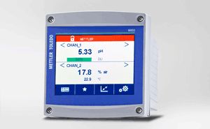
![]()
Код товара:
069-862-007
![]()
Госреестр:
Госреестр
![]()
Доставка по России
Описание
Трансмиттер М400 описание
M400 двухпроводной трансмиттер
Промышленный двухпроводной трансмиттер М400
— для применения в опасных зонах на предприятиях химической промышленности
Cистема цифрового управления датчиками (ISM), разрешения на применение в опасных зонах по всему миру и прочная конструкция двухпроводного трансмиттера серии М400 — все это обеспечивает непревзойденную эксплуатационную надежность и безопасность производственных процессов. Эти особенности гарантируют, что трансмиттеры серии M400 пригодны для использования на всех химических производствах. Прибор прост в эксплуатации, позволяет осуществлять доступ к расширенным инструментам автоматической диагностики ISM как на месте измерений, так и удаленно по протоколу связи HART. Таким образом сокращаются эксплуатационные расходы и увеличивается период работоспособности.
Двухпроводной трансмиттер M400 — это одноканальный многопараметрический прибор для измерения рН/ОВП, содержания кислорода и электропроводности. Благодаря совмещенному режиму ввода, позволяющему использовать как аналоговые датчики, так и датчики, использующие технологию ISM, двухпроводной трансмиттер М400 предлагает уникальный и удобный переход от аналоговых устройств к цифровой технологии.
Особенности и преимущества:
- Непревзойденная надежность и безопасность производственных процессов
- Профилактическое техническое обслуживание
- Простота обращения с контурами измерения
- Универсальность
Технические характеристики — M400 2-проводной
| ISM | Подключи и измеряй, ACT (Адаптивный калибровочный таймер), TTM (Время до очередного технического обслуживания), DLI (Динамическая индикация срока службы датчика) |
| Approvals | NEPSI Ex, ATEX / IECEx Zone1, cFMus Class 1 Div 1 |
| Цифровой вход / выход | Вход: 2, гальванически развязаны. Выход: 2 х разомкнутый коллектор |
| Токовый выход | 2 х 4 до 20 мА (питание от контура), гальванически развязаны |
| Передача данных | HART, FOUNDATION fieldbus, PROFIBUS PA |
| Температурный интервал | 20…60C ( 4…140F) |
| Measurement parameter | pH/ОВП, pH/pNa, DO (растворенный кислород), Cond (Электропроводность) 2E/4E, GPO |
| Параметр | pH/ОВП, растворенный кислород, газообразный O2, электропроводность |
| Классификация взрывоопасных зон | M400/2H: зона 2 по NEPSI, класс 1 раздел 2 по FM (выполняется) M400(G)/2XH: зона 1 по ATEX, зона 1 NEPSI, класс 1 раздел 1 FM (выполняется) |
| Тип датчика | Аналоговый или ISM |
Отзывы
Отзывы о М400 — Промышленный двухпроводной трансмиттер
Вы недавно смотрели