-
Contents
-
Table of Contents
-
Bookmarks
Quick Links
Maxum II
PD PA AP
Explosion Protection Safety
Standards
Manual
August 2017
A5E02220442001 Rev 8
General Information for the
User
Safety Systems — Purging
Safety Systems — Oven
Valves, Detectors, and
External Systems
Safe Operation
1
2
3
4
5
Related Manuals for Siemens Maxum II
Summary of Contents for Siemens Maxum II
-
Page 1
General Information for the User Safety Systems — Purging Safety Systems — Oven Maxum II Valves, Detectors, and External Systems PD PA AP Explosion Protection Safety Safe Operation Standards Manual August 2017 A5E02220442001 Rev 8… -
Page 2
Note the following: WARNING Siemens products may only be used for the applications described in the catalog and in the relevant technical documentation. If products and components from other manufacturers are used, these must be recommended or approved by Siemens. Proper transport, storage, installation, assembly, commissioning, operation and maintenance are required to ensure that the products operate safely and without any problems. -
Page 3: Table Of Contents
Table of contents General Information for the User……………………7 Contacts……………………..10 Approved Use……………………11 Qualified Personnel……………………11 Applicable Standards and Regulations………………12 Safety Protection Principles………………..13 Intrinsically Safe Devices…………………..14 Safety Systems — Purging………………………17 Purging Overview……………………17 Electronics Purging System (without Automatic Purge Unit)……….18 2.2.1 Overview……………………..18 2.2.2 Instrument Air Inlet and Regulator………………20 2.2.3 Fast Purge Switch……………………21 2.2.4…
-
Page 4
4.4.2 Methanator Maintenance Considerations…………….55 Safe Operation……………………….57 Maintenance Panel Functional Description…………….57 Maintenance Considerations for Maintenance Panel………….58 Color Touchscreen Display Functional Description……………58 Maintenance Considerations for Control Interface Module Display……..59 Steps for Safe Startup of Maxum II………………60 5.5.1 Overview……………………..60 5.5.2 Procedure……………………..60 Glossary…………………………63 Figures Figure 1-1 Reference of Hardware (MAA) to Applicable Sections of this Manual……….8… -
Page 5
Figure 4-1 Siemens Liquid Injection Valve………………..45 Figure 4-2 Siemens Liquid Injection Valve (Installed)……………….46 Figure 4-3 Heater for Siemens Liquid Injection Valve………………46 Figure 4-4 Explosion Proof/Flameproof Thermal Conductivity Detector…………49 Figure 4-5 Thermal Conductivity Detector Beads on Modular Oven Application Module (Intrinsically Safe TCD)………………………50… -
Page 6
Table of contents Explosion Protection Safety Standards Manual, August 2017, A5E02220442001 Rev 8… -
Page 7: General Information For The User
These standards are to ensure that the Maxum II and related products can be safely installed and operated in hazardous areas. Each individual detail and component of these safety systems is important to help ensure that the chromatograph does not ignite flammable vapors and gases which may be present in the environment surrounding the analyzer.
-
Page 8: Figure 1-1 Reference Of Hardware (Maa) To Applicable Sections Of This Manual
General Information for the User Exhaust Di user Electronics Automatic Purge Unit (APU) Sections 2.2, 2.3 Enclosure (Purged) or Pressure Relief Valve Sections 2.2, 2.3 (Inside Enclosure) Sections 2.2, 2.3 Proportinal Valve for APU (Section 2.3) or Signal Disconnect Purge Control Module Relay for APU (Section 2.2) Section 2.3…
-
Page 9
Trademarks All names identified by ® are registered trademarks of Siemens AG. The remaining trademarks in this publication may be trademarks whose use by third parties for their own purposes could violate the rights of the owner. -
Page 10: Contacts
General Information for the User 1.1 Contacts Contacts Register at the Siemens Industry Online Support (SIOS) website: https://support.industry.siemens.com International Siemens AG Siemens Industry, Inc. I IA SC PA PM Process Analytics 5980 West Sam Houston Parkway North Oestliche Rheinbrueckenstrasse 50…
-
Page 11: Approved Use
Low voltages which are connected must also be generated using safe isolation. If any part of the Maxum II is opened, certain parts of the device are accessible which may carry dangerous voltages. Therefore, only suitably qualified personnel may work on this device as indicated in the next section which is titled «Qualified Personnel».
-
Page 12: Applicable Standards And Regulations
The ATEX certificate for the Modular Oven Configuration is Sira 12ATEX1260X and comes with the following conditions for safe use: ● The Maxum II Modular Oven Gas Chromatograph shall be fitted with cable glands or conduit entries having an IP54 minimum rating.
-
Page 13: Safety Protection Principles
The protection principles used depend on such factors as the type of device, the certifying organization that is applicable for the site, and the type of environment. Table 1-2 details some of the protection principles used in the Maxum II along with the hardware that uses those protection principles.
-
Page 14: Intrinsically Safe Devices
IS‑TCD and the connections to the CIM touch screen display. Intrinsic safety protection for circuits and devices within the Maxum II enclosure is designed to conform to IEC EN60079-11. This is the standard that is applicable to factory installed electrical components and also for circuits that are additionally protected by other methods, such as a purged Maxum enclosure.
-
Page 15
● Maintenance for intrinsically safe devices, such as the IS-TCD, is limited to replacement. Repair or service on-site are not permitted. ● Intrinsically safe devices in the Maxum II that are equipped with a cover must have the cover attached during use. Leaving the cover off can violate requirements pertaining to mandatory separation from non-IS wiring. -
Page 16
General Information for the User 1.6 Intrinsically Safe Devices Explosion Protection Safety Standards Manual, August 2017, A5E02220442001 Rev 8… -
Page 17: Safety Systems — Purging
The primary electronic devices of the Maxum II analyzer are housed inside the electronics enclosure (see Figures 1-1 and 1-2). All electronics in the Maxum II are designed to meet North American Division 2 and European Zone 2 safety requirements. This means that these electronics will not cause combustion of flammable vapors or gases under normal conditions.
-
Page 18: Electronics Purging System (Without Automatic Purge Unit)
2.2.1 Overview The standard purging system of the Maxum II is controlled by the Power Entry Control Module (PECM) and the processor board (either SYSCON or CIM, depending on the Maxum II configuration). In the standard purging configuration, an alarm is generated whenever purging pressure is lost.
-
Page 19: Figure 2-2 Electronics Pressurization System (Type Py) For Airbath/Airless Oven Model (Old Pressure Relief Valve Configuration)
Safety Systems — Purging 2.2 Electronics Purging System (without Automatic Purge Unit) Instrument Air System Controller Input — “Clean (SYSCON) Regulator and Dry” Electronics Purge Enclosure Purge Signal Warning Cable Light PECM to Purge SYSCON Power Entry Purge Control Control Module Pressure Sensor Module (PCM) (PECM)
-
Page 20: Instrument Air Inlet And Regulator
Depending on the configuration of the Maxum II, the regulator may be labeled as either «Purge» or «Isothermal Oven Air» (refer to the section of this manual regarding Isothermal Ovens for more information). The purge air is connected to the purged electronics enclosure through two possible paths, the «normal»…
-
Page 21: Fast Purge Switch
Safety Systems — Purging 2.2 Electronics Purging System (without Automatic Purge Unit) 2.2.3 Fast Purge Switch The fast purge control switch, which is shown in the following figure, is located inside the detector enclosure (middle door) or near the purge air regulator as shown in the figure below. This switch is operated by the user and is used to re-purge the electronics enclosure for a period of 8 minutes after the sealed enclosure has been opened and then re-sealed.
-
Page 22: Figure 2-5 Fast Purge Switch (Shown In The Off Position)
Safety Systems — Purging 2.2 Electronics Purging System (without Automatic Purge Unit) Modular Oven Airbath/Airless Oven Modular Oven fast-purge switch label for Div 2 Modular Oven fast-purge switch label for Div 1 / Zone 1 Figure 2-5 Fast Purge Switch (Shown in the Off Position) Explosion Protection Safety Standards Manual, August 2017, A5E02220442001 Rev 8…
-
Page 23: Purge Control Module
(either SYSCON or CIM, depending on configuration). The SYSCON or CIM then generates an alarm and flashes the purge alarm LED on the front door of the Maxum II analyzer electronics enclosure. The purge alarm LED flashes red when an alarm is present.
-
Page 24: Pressure Sensor And Atmospheric Pressure Reference
Control Module (PECM). PECM may refer to either the PECM or PECM-DC, depending on the Maxum II configuration. Located on this module is a pressure sensor (Figure 2-7) that detects the pressure inside the enclosure and compares it to the pressure outside the enclosure.
-
Page 25: Fast Purge Pressure Relief Valve
The pressure relief valve, which is shown in the following figure, is located either inside the detector enclosure (middle door or a Maxum II with Airbath/Airless oven) or inside the top left of the electronics enclosure for a Maxum II Modular Oven. The location of the pressure relief valve within the analyzer is shown in Figures 2-1 and 2-2.
-
Page 26: Electronics Purging System (With Automatic Purge Unit)
Power and all other external wiring that enters the Maxum II is disconnected by the APU whenever purge is lost. This is referred to as purging with Type X pressurization (px). The APU is available in Maxum II Airbath/Airless Oven and the Maxum II Modular Oven configurations.
-
Page 27: Purge Air Inlet And Regulator
Safety Systems — Purging 2.3 Electronics Purging System (with Automatic Purge Unit) 2.3.2 Purge Air Inlet and Regulator This is a pressure regulator with air input that is connected to an instrument air source. The regulator is necessary to ensure that the input pressure does not exceed a certain value. Excessive pressure could damage other components in the purging system.
-
Page 28: Proportional Valve
8 minutes before power is connected to remove potentially hazardous levels of flammable gases and vapors from the analyzer before power up. The APU is mounted inside the electronics enclosure of the Maxum II as shown in the following figure. Explosion Protection Safety Standards…
-
Page 29: Maintenance Switch
Safety Systems — Purging 2.3 Electronics Purging System (with Automatic Purge Unit) Figure 2-14 Automatic Purge Control Unit (APU) shown in Airless/Airbath model 2.3.5 Maintenance Switch This device allows a user to override the power cutoff function of the APU for maintenance purposes.
-
Page 30: Exhaust Diffuser
Safety Systems — Purging 2.3 Electronics Purging System (with Automatic Purge Unit) Figure 2-15 Location and Close-Up of Maintenance Switch (MAA, Set for Normal Operation) The maintenance switch for the MMO configuration is on the top left of the regulator panel, to the right of the electronics enclosure.
-
Page 31: Signal Disconnect Relay
Safety Systems — Purging 2.3 Electronics Purging System (with Automatic Purge Unit) Figure 2-17 Covered Purge Exhaust Diffuser 2.3.7 Signal Disconnect Relay The Signal Disconnect Relay is mounted externally to the analyzer. This relay disconnects all external wiring to the analyzer except for power to the APU. The Signal Disconnect Relay is controlled by the APU which deactivates the relay when purge pressure is lost.
-
Page 32: Maintenance Considerations For Purged Systems
Signal Disconnect Relays Maintenance Considerations for Purged Systems The following practices must be observed in order to operate, maintain and prevent compromise of the Maxum II purging system. WARNING Avoid Equipment Contamination or Ignition of Explosive Gases Failure to correctly observe the following practices may result in a dangerous situation that could lead to severe personal injury or death and/or extensive property damage.
-
Page 33
A reference tube (see Figure 2-8) is used for this purpose. This tube must not be obstructed. Air does not flow through this tube. The tube is intended to sample the pressure immediately outside the Maxum II enclosure, and it should not be lengthened, shortened, or altered in any way. -
Page 34
Safety Systems — Purging 2.4 Maintenance Considerations for Purged Systems ● The Maxum II Analyzer should be visually inspected at regular intervals to ensure the integrity of the purge system. The following inspections should be made: – Instrument air lines and fittings should be inspected for leaks and damage. -
Page 35: Safety Systems — Oven
This is accomplished by the oven heater system. A variety of oven configurations are available for the Maxum II. For isothermal (single set temperature) analyses air bath, airless, and modular ovens are available. Since the Maxum II…
-
Page 36: Isothermal Air Bath Oven Heater System (Single And Split)
Isothermal Air Bath Oven Heater System (Single and Split) The isothermal air bath oven is the most common oven used in the Maxum II. It is available in single and split configurations to accommodate a wide range of chromatographic applications.
-
Page 37: Temperature Control
Safety Systems — Oven 3.2 Isothermal Air Bath Oven Heater System (Single and Split) Figure 3-2 Timing Coil for Pressure Switch See also Safety Systems — Purging (Page 17) 3.2.2 Temperature Control As mentioned in section 3.1, the temperature of the oven is controlled via an RTD sensor. The temperature of the air itself is controlled via two independent sensors which work with the two set point resistors mentioned in section 3.1 to ensure that all temperatures remain below possible ignition limits.
-
Page 38: Programmed Temperature Air Bath Oven Heater System (Split)
Within the Maxum II, temperature control and air purging of the air bath heater is the same for the programmed temperature oven as for the isothermal air bath oven.
-
Page 39: Isothermal Airless Oven Heater System (Split)
3.4 Isothermal Airless Oven Heater System (Split) Isothermal Airless Oven Heater System (Split) The Maxum II airless oven is used to provide a very stable isothermal oven temperature without the need to supply oven air to the analyzer. This allows for excellent chromatographic results while reducing utility costs.
-
Page 40
Safety Systems — Oven 3.4 Isothermal Airless Oven Heater System (Split) Insert Location for RTD Probe (Same as on Opposite Side) Channel for Heating Element Figure 3-5 Location of Temperature Probes and Heaters on Airless Oven The heating elements are enclosed in hollow tubes running diagonally down the side of the aluminum casing. -
Page 41: Maintenance Considerations For Air Bath And Airless Ovens
(including programmed temperature oven) and airless ovens of Maxum II. Modular ovens are described in the next section. ● It must be ensured that the analyzer T-rating is suitable for the area in which the analyzer is to be installed.
-
Page 42: Modular Oven Heater System
3.6 Modular Oven Heater System Modular Oven Heater System The Maxum II Modular Oven is used to provide a stable isothermal oven temperature for certain lower temperature applications. This allows for excellent chromatographic results at a greatly reduced product cost and simplified and low cost operation and maintenance for the applicable range of applications.
-
Page 43: Maintenance Considerations Modular Ovens
Maintenance Considerations Modular Ovens The following practices must be observed in order to operate, maintain and prevent compromise of the Maxum II Modular Oven heater system. ● The installaion of the heater elements and RTDs should be inspected to verify that they are fully inserted into the tubes as shown in the previous section.
-
Page 44
Safety Systems — Oven 3.7 Maintenance Considerations Modular Ovens Explosion Protection Safety Standards Manual, August 2017, A5E02220442001 Rev 8… -
Page 45: Valves, Detectors, And External Systems
4.1.1 SLIV Functional Description Some applications require the use of a heated Siemens Liquid Injection Valve (SLIV) which is shown in figure 4-1. This valve is generally mounted through a side wall of the analyzer oven (refer to figure 4-2). The narrow portion of the valve that extends into the oven is known as the vaporizer.
-
Page 46: Sliv Maintenance Considerations
4.1.2 SLIV Maintenance Considerations The Siemens Liquid Injection Valve (SLIV) should be inspected to assure that it is free of physical damage. All tubing and conduit connections should be correctly installed and tightened as prescribed by local safety requirements. Whenever maintenance is performed on the valve, care must be taken not to damage the temperature sensors and the heater element which are inserted in the valve body.
-
Page 47: Detectors
Detector Functional Descriptions In order to analyze the chemical compositions of different samples, four major types of detectors are used in the Maxum II Gas Chromatograph (refer to figures 4-4 through 4-6). The types of detectors are: ● Explosion Proof/Flameproof Thermal Conductivity Detector (TCD) ●…
-
Page 48: Detector Maintenance Considerations
For most detectors within the Maxum II, protection is accomplished by enclosing the active elements in a flameproof/explosion proof housing. In these cases electrical, optical and gas connections must penetrate the housing of the detector.
-
Page 49
Valves, Detectors, and External Systems 4.2 Detectors The circuits for the IS-TCD require special considerations to ensure that the circuit remains intrinsically safe. For important information on the safe use of intrinsically safe circuits, refer to the sections of this manual labeled «Intrinsically Safe Devices». Figure 4-4 Explosion Proof/Flameproof Thermal Conductivity Detector Explosion Protection Safety Standards… -
Page 50
Valves, Detectors, and External Systems 4.2 Detectors Figure 4-5 Thermal Conductivity Detector Beads on Modular Oven Application Module (Intrinsically Safe TCD) Explosion Protection Safety Standards Manual, August 2017, A5E02220442001 Rev 8… -
Page 51
Valves, Detectors, and External Systems 4.2 Detectors Figure 4-6 Flame Ionization Detector (without Insulation and Cover) Figure 4-7 Flame Photometric Detector (without Insulation and Cover) Explosion Protection Safety Standards Manual, August 2017, A5E02220442001 Rev 8… -
Page 52: Air Treater
4.3.1 Air Treater Functional Description To provide clean air for the Flame Ionization Detector (FID), the Maxum II uses a catalytic device known as an Air Treater (figure 4-8) to remove hydrocarbons from ordinary plant instrument air. The Air Treater is an independent unit mounted near the Maxum II. It consists of an extremely hot combustion chamber and a catalyst.
-
Page 53: Air Treater Maintenance Considerations
Two versions of the methanator exist for use in the Maxum. The original is protected by purging/ pressurization. The more recent version is protected in an explosion proof enclosure. Both versions are designed to install in the detector enclosure of the Maxum II Airbath/Airless Oven configuration (refer to figure 1-1).
-
Page 54
When the purged/pressurized version of the methanator is installed, if the purge air supply of the Maxum II is interrupted during operation, it is imperative that the analyzer be powered down. Once powered down, the electronics enclosure door must be kept closed for at least 30 minutes. -
Page 55: Methanator Maintenance Considerations
Valves, Detectors, and External Systems 4.4 Methanator Figure 4-10 Explosion Proof Methanator (Both Versions) As protection measure, the gas inlets and outlets that enter and leave the methanator are configured as flame arrestors (refer to figure 4-8 and 4-9). In addition, both versions of the methanator assembly are insulated to prevent the surface temperature of the methanator from exceeding 180°C (surface temperatures for the explosion proof/flameproof methanator are significantly lower than 180°C).
-
Page 56
Valves, Detectors, and External Systems 4.4 Methanator never be cut or shortened or bent or bypassed in any way. If there is any physical damage, the device should be shut down until it can be replaced. WARNING The purged/pressurized methanator must not be operated without purge/pressurization unless it has been verified that the area is free of explosive gases and vapors. -
Page 57: Safe Operation
PC-based System Manager software and also via a user access display panel that is mounted on the front door of the Maxum II electronics enclosure. Two types of display panel exist, both of which can be used to perform the same user functions. The newest version is the Color Touchscreen display, which is described in section 5-3.
-
Page 58: Maintenance Considerations For Maintenance Panel
If an APU is not installed, the «Purge» LED flashes when purge pressure is lost. The «Power» LED is lit at all times when power is applied to the analyzer. Note that the «Fault» and «Warning» LEDs are related to the trouble reporting systems of the Maxum II but are not applicable to the safety systems.
-
Page 59: Maintenance Considerations For Control Interface Module Display
Maxum II Use of the display for maintenance and operation functions is covered in the Reference Manual and the Maxum II Reference Manual, Modular Oven Configuration . Note In addition to the display installed on the analyzer, there is an emulator (called HMI emulator) available through the PC-based workstation software.
-
Page 60: Steps For Safe Startup Of Maxum Ii
Overview The startup procedure described in this section explains the principle steps necessary to power the Maxum II in a manner that does not compromise the safety systems that have been described in this manual. This section does not explain the startup procedures required that relate to software functions or the analytical application of the analyzer.
-
Page 61
Safe Operation 5.5 Steps for Safe Startup of Maxum II Note The remainder of the startup process is dependent on whether an APU is installed. (If APU is not equipped) Turn on the fast purge switch (figure 2-4) and allow fast purge air to flow for at least 8 minutes. -
Page 62
Safe Operation 5.5 Steps for Safe Startup of Maxum II Explosion Protection Safety Standards Manual, August 2017, A5E02220442001 Rev 8… -
Page 63: Glossary
115 VAC or 230VAC and converts to 24V DC for distribution within the analyzer. Air Bath Oven One of three primary types of oven available for the Maxum II. Heating of the oven is accomplished by passing air over a heating element and into the oven. Available as a single oven or it can be split into two independent oven compartments.
-
Page 64
Glossary Detector Compartment The middle section of a Maxum II Chromatograph that is equipped with either Airbath or Airless oven. It houses various detectors that may be equipped in the Maxum II Airbath/Airless Oven. It also houses the Methanator, if equipped. -
Page 65
CSA term for this concept is non-incendive. Oven Compartment The bottom area of a Maxum II that houses the ovens. Depending on the configuration of the Maxum II, this may be a Modular Oven Compartment or an Airbath/Airless Oven Compartment. -
Page 66
Temperature Programming The process of increasing oven temperature incrementally in order to reduce the time needed to separate a sample using a chromatograph. In the Maxum II, a variant of the air bath oven may be used to employ temperature programming. -
Page 67
A purged system where an alarm is generated whenever purge pressure is lost. In addition, any equipment which would exceed the T-Rating of the location upon loss of air flow (such as the Maxum II air bath oven heater) must be de-energized when purge is lost. Zone 1 An atmosphere where a mixture of air and flammable substances in the form of gas, vapor, or mist is likely to occur in normal operation occasionally. -
Page 68
Glossary Explosion Protection Safety Standards Manual, August 2017, A5E02220442001 Rev 8…
-
Contents
-
Table of Contents
-
Bookmarks
Quick Links
Maxum II
PD PA AP
Explosion Protection Safety
Standards
Manual
August 2017
A5E02220442001 Rev 8
General Information for the
User
Safety Systems — Purging
Safety Systems — Oven
Valves, Detectors, and
External Systems
Safe Operation
1
2
3
4
5
Related Manuals for Siemens Maxum II
Summary of Contents for Siemens Maxum II
-
Page 1
General Information for the User Safety Systems — Purging Safety Systems — Oven Maxum II Valves, Detectors, and External Systems PD PA AP Explosion Protection Safety Safe Operation Standards Manual August 2017 A5E02220442001 Rev 8… -
Page 2
Note the following: WARNING Siemens products may only be used for the applications described in the catalog and in the relevant technical documentation. If products and components from other manufacturers are used, these must be recommended or approved by Siemens. Proper transport, storage, installation, assembly, commissioning, operation and maintenance are required to ensure that the products operate safely and without any problems. -
Page 3: Table Of Contents
Table of contents General Information for the User……………………7 Contacts……………………..10 Approved Use……………………11 Qualified Personnel……………………11 Applicable Standards and Regulations………………12 Safety Protection Principles………………..13 Intrinsically Safe Devices…………………..14 Safety Systems — Purging………………………17 Purging Overview……………………17 Electronics Purging System (without Automatic Purge Unit)……….18 2.2.1 Overview……………………..18 2.2.2 Instrument Air Inlet and Regulator………………20 2.2.3 Fast Purge Switch……………………21 2.2.4…
-
Page 4
4.4.2 Methanator Maintenance Considerations…………….55 Safe Operation……………………….57 Maintenance Panel Functional Description…………….57 Maintenance Considerations for Maintenance Panel………….58 Color Touchscreen Display Functional Description……………58 Maintenance Considerations for Control Interface Module Display……..59 Steps for Safe Startup of Maxum II………………60 5.5.1 Overview……………………..60 5.5.2 Procedure……………………..60 Glossary…………………………63 Figures Figure 1-1 Reference of Hardware (MAA) to Applicable Sections of this Manual……….8… -
Page 5
Figure 4-1 Siemens Liquid Injection Valve………………..45 Figure 4-2 Siemens Liquid Injection Valve (Installed)……………….46 Figure 4-3 Heater for Siemens Liquid Injection Valve………………46 Figure 4-4 Explosion Proof/Flameproof Thermal Conductivity Detector…………49 Figure 4-5 Thermal Conductivity Detector Beads on Modular Oven Application Module (Intrinsically Safe TCD)………………………50… -
Page 6
Table of contents Explosion Protection Safety Standards Manual, August 2017, A5E02220442001 Rev 8… -
Page 7: General Information For The User
These standards are to ensure that the Maxum II and related products can be safely installed and operated in hazardous areas. Each individual detail and component of these safety systems is important to help ensure that the chromatograph does not ignite flammable vapors and gases which may be present in the environment surrounding the analyzer.
-
Page 8: Figure 1-1 Reference Of Hardware (Maa) To Applicable Sections Of This Manual
General Information for the User Exhaust Di user Electronics Automatic Purge Unit (APU) Sections 2.2, 2.3 Enclosure (Purged) or Pressure Relief Valve Sections 2.2, 2.3 (Inside Enclosure) Sections 2.2, 2.3 Proportinal Valve for APU (Section 2.3) or Signal Disconnect Purge Control Module Relay for APU (Section 2.2) Section 2.3…
-
Page 9
Trademarks All names identified by ® are registered trademarks of Siemens AG. The remaining trademarks in this publication may be trademarks whose use by third parties for their own purposes could violate the rights of the owner. -
Page 10: Contacts
General Information for the User 1.1 Contacts Contacts Register at the Siemens Industry Online Support (SIOS) website: https://support.industry.siemens.com International Siemens AG Siemens Industry, Inc. I IA SC PA PM Process Analytics 5980 West Sam Houston Parkway North Oestliche Rheinbrueckenstrasse 50…
-
Page 11: Approved Use
Low voltages which are connected must also be generated using safe isolation. If any part of the Maxum II is opened, certain parts of the device are accessible which may carry dangerous voltages. Therefore, only suitably qualified personnel may work on this device as indicated in the next section which is titled «Qualified Personnel».
-
Page 12: Applicable Standards And Regulations
The ATEX certificate for the Modular Oven Configuration is Sira 12ATEX1260X and comes with the following conditions for safe use: ● The Maxum II Modular Oven Gas Chromatograph shall be fitted with cable glands or conduit entries having an IP54 minimum rating.
-
Page 13: Safety Protection Principles
The protection principles used depend on such factors as the type of device, the certifying organization that is applicable for the site, and the type of environment. Table 1-2 details some of the protection principles used in the Maxum II along with the hardware that uses those protection principles.
-
Page 14: Intrinsically Safe Devices
IS‑TCD and the connections to the CIM touch screen display. Intrinsic safety protection for circuits and devices within the Maxum II enclosure is designed to conform to IEC EN60079-11. This is the standard that is applicable to factory installed electrical components and also for circuits that are additionally protected by other methods, such as a purged Maxum enclosure.
-
Page 15
● Maintenance for intrinsically safe devices, such as the IS-TCD, is limited to replacement. Repair or service on-site are not permitted. ● Intrinsically safe devices in the Maxum II that are equipped with a cover must have the cover attached during use. Leaving the cover off can violate requirements pertaining to mandatory separation from non-IS wiring. -
Page 16
General Information for the User 1.6 Intrinsically Safe Devices Explosion Protection Safety Standards Manual, August 2017, A5E02220442001 Rev 8… -
Page 17: Safety Systems — Purging
The primary electronic devices of the Maxum II analyzer are housed inside the electronics enclosure (see Figures 1-1 and 1-2). All electronics in the Maxum II are designed to meet North American Division 2 and European Zone 2 safety requirements. This means that these electronics will not cause combustion of flammable vapors or gases under normal conditions.
-
Page 18: Electronics Purging System (Without Automatic Purge Unit)
2.2.1 Overview The standard purging system of the Maxum II is controlled by the Power Entry Control Module (PECM) and the processor board (either SYSCON or CIM, depending on the Maxum II configuration). In the standard purging configuration, an alarm is generated whenever purging pressure is lost.
-
Page 19: Figure 2-2 Electronics Pressurization System (Type Py) For Airbath/Airless Oven Model (Old Pressure Relief Valve Configuration)
Safety Systems — Purging 2.2 Electronics Purging System (without Automatic Purge Unit) Instrument Air System Controller Input — “Clean (SYSCON) Regulator and Dry” Electronics Purge Enclosure Purge Signal Warning Cable Light PECM to Purge SYSCON Power Entry Purge Control Control Module Pressure Sensor Module (PCM) (PECM)
-
Page 20: Instrument Air Inlet And Regulator
Depending on the configuration of the Maxum II, the regulator may be labeled as either «Purge» or «Isothermal Oven Air» (refer to the section of this manual regarding Isothermal Ovens for more information). The purge air is connected to the purged electronics enclosure through two possible paths, the «normal»…
-
Page 21: Fast Purge Switch
Safety Systems — Purging 2.2 Electronics Purging System (without Automatic Purge Unit) 2.2.3 Fast Purge Switch The fast purge control switch, which is shown in the following figure, is located inside the detector enclosure (middle door) or near the purge air regulator as shown in the figure below. This switch is operated by the user and is used to re-purge the electronics enclosure for a period of 8 minutes after the sealed enclosure has been opened and then re-sealed.
-
Page 22: Figure 2-5 Fast Purge Switch (Shown In The Off Position)
Safety Systems — Purging 2.2 Electronics Purging System (without Automatic Purge Unit) Modular Oven Airbath/Airless Oven Modular Oven fast-purge switch label for Div 2 Modular Oven fast-purge switch label for Div 1 / Zone 1 Figure 2-5 Fast Purge Switch (Shown in the Off Position) Explosion Protection Safety Standards Manual, August 2017, A5E02220442001 Rev 8…
-
Page 23: Purge Control Module
(either SYSCON or CIM, depending on configuration). The SYSCON or CIM then generates an alarm and flashes the purge alarm LED on the front door of the Maxum II analyzer electronics enclosure. The purge alarm LED flashes red when an alarm is present.
-
Page 24: Pressure Sensor And Atmospheric Pressure Reference
Control Module (PECM). PECM may refer to either the PECM or PECM-DC, depending on the Maxum II configuration. Located on this module is a pressure sensor (Figure 2-7) that detects the pressure inside the enclosure and compares it to the pressure outside the enclosure.
-
Page 25: Fast Purge Pressure Relief Valve
The pressure relief valve, which is shown in the following figure, is located either inside the detector enclosure (middle door or a Maxum II with Airbath/Airless oven) or inside the top left of the electronics enclosure for a Maxum II Modular Oven. The location of the pressure relief valve within the analyzer is shown in Figures 2-1 and 2-2.
-
Page 26: Electronics Purging System (With Automatic Purge Unit)
Power and all other external wiring that enters the Maxum II is disconnected by the APU whenever purge is lost. This is referred to as purging with Type X pressurization (px). The APU is available in Maxum II Airbath/Airless Oven and the Maxum II Modular Oven configurations.
-
Page 27: Purge Air Inlet And Regulator
Safety Systems — Purging 2.3 Electronics Purging System (with Automatic Purge Unit) 2.3.2 Purge Air Inlet and Regulator This is a pressure regulator with air input that is connected to an instrument air source. The regulator is necessary to ensure that the input pressure does not exceed a certain value. Excessive pressure could damage other components in the purging system.
-
Page 28: Proportional Valve
8 minutes before power is connected to remove potentially hazardous levels of flammable gases and vapors from the analyzer before power up. The APU is mounted inside the electronics enclosure of the Maxum II as shown in the following figure. Explosion Protection Safety Standards…
-
Page 29: Maintenance Switch
Safety Systems — Purging 2.3 Electronics Purging System (with Automatic Purge Unit) Figure 2-14 Automatic Purge Control Unit (APU) shown in Airless/Airbath model 2.3.5 Maintenance Switch This device allows a user to override the power cutoff function of the APU for maintenance purposes.
-
Page 30: Exhaust Diffuser
Safety Systems — Purging 2.3 Electronics Purging System (with Automatic Purge Unit) Figure 2-15 Location and Close-Up of Maintenance Switch (MAA, Set for Normal Operation) The maintenance switch for the MMO configuration is on the top left of the regulator panel, to the right of the electronics enclosure.
-
Page 31: Signal Disconnect Relay
Safety Systems — Purging 2.3 Electronics Purging System (with Automatic Purge Unit) Figure 2-17 Covered Purge Exhaust Diffuser 2.3.7 Signal Disconnect Relay The Signal Disconnect Relay is mounted externally to the analyzer. This relay disconnects all external wiring to the analyzer except for power to the APU. The Signal Disconnect Relay is controlled by the APU which deactivates the relay when purge pressure is lost.
-
Page 32: Maintenance Considerations For Purged Systems
Signal Disconnect Relays Maintenance Considerations for Purged Systems The following practices must be observed in order to operate, maintain and prevent compromise of the Maxum II purging system. WARNING Avoid Equipment Contamination or Ignition of Explosive Gases Failure to correctly observe the following practices may result in a dangerous situation that could lead to severe personal injury or death and/or extensive property damage.
-
Page 33
A reference tube (see Figure 2-8) is used for this purpose. This tube must not be obstructed. Air does not flow through this tube. The tube is intended to sample the pressure immediately outside the Maxum II enclosure, and it should not be lengthened, shortened, or altered in any way. -
Page 34
Safety Systems — Purging 2.4 Maintenance Considerations for Purged Systems ● The Maxum II Analyzer should be visually inspected at regular intervals to ensure the integrity of the purge system. The following inspections should be made: – Instrument air lines and fittings should be inspected for leaks and damage. -
Page 35: Safety Systems — Oven
This is accomplished by the oven heater system. A variety of oven configurations are available for the Maxum II. For isothermal (single set temperature) analyses air bath, airless, and modular ovens are available. Since the Maxum II…
-
Page 36: Isothermal Air Bath Oven Heater System (Single And Split)
Isothermal Air Bath Oven Heater System (Single and Split) The isothermal air bath oven is the most common oven used in the Maxum II. It is available in single and split configurations to accommodate a wide range of chromatographic applications.
-
Page 37: Temperature Control
Safety Systems — Oven 3.2 Isothermal Air Bath Oven Heater System (Single and Split) Figure 3-2 Timing Coil for Pressure Switch See also Safety Systems — Purging (Page 17) 3.2.2 Temperature Control As mentioned in section 3.1, the temperature of the oven is controlled via an RTD sensor. The temperature of the air itself is controlled via two independent sensors which work with the two set point resistors mentioned in section 3.1 to ensure that all temperatures remain below possible ignition limits.
-
Page 38: Programmed Temperature Air Bath Oven Heater System (Split)
Within the Maxum II, temperature control and air purging of the air bath heater is the same for the programmed temperature oven as for the isothermal air bath oven.
-
Page 39: Isothermal Airless Oven Heater System (Split)
3.4 Isothermal Airless Oven Heater System (Split) Isothermal Airless Oven Heater System (Split) The Maxum II airless oven is used to provide a very stable isothermal oven temperature without the need to supply oven air to the analyzer. This allows for excellent chromatographic results while reducing utility costs.
-
Page 40
Safety Systems — Oven 3.4 Isothermal Airless Oven Heater System (Split) Insert Location for RTD Probe (Same as on Opposite Side) Channel for Heating Element Figure 3-5 Location of Temperature Probes and Heaters on Airless Oven The heating elements are enclosed in hollow tubes running diagonally down the side of the aluminum casing. -
Page 41: Maintenance Considerations For Air Bath And Airless Ovens
(including programmed temperature oven) and airless ovens of Maxum II. Modular ovens are described in the next section. ● It must be ensured that the analyzer T-rating is suitable for the area in which the analyzer is to be installed.
-
Page 42: Modular Oven Heater System
3.6 Modular Oven Heater System Modular Oven Heater System The Maxum II Modular Oven is used to provide a stable isothermal oven temperature for certain lower temperature applications. This allows for excellent chromatographic results at a greatly reduced product cost and simplified and low cost operation and maintenance for the applicable range of applications.
-
Page 43: Maintenance Considerations Modular Ovens
Maintenance Considerations Modular Ovens The following practices must be observed in order to operate, maintain and prevent compromise of the Maxum II Modular Oven heater system. ● The installaion of the heater elements and RTDs should be inspected to verify that they are fully inserted into the tubes as shown in the previous section.
-
Page 44
Safety Systems — Oven 3.7 Maintenance Considerations Modular Ovens Explosion Protection Safety Standards Manual, August 2017, A5E02220442001 Rev 8… -
Page 45: Valves, Detectors, And External Systems
4.1.1 SLIV Functional Description Some applications require the use of a heated Siemens Liquid Injection Valve (SLIV) which is shown in figure 4-1. This valve is generally mounted through a side wall of the analyzer oven (refer to figure 4-2). The narrow portion of the valve that extends into the oven is known as the vaporizer.
-
Page 46: Sliv Maintenance Considerations
4.1.2 SLIV Maintenance Considerations The Siemens Liquid Injection Valve (SLIV) should be inspected to assure that it is free of physical damage. All tubing and conduit connections should be correctly installed and tightened as prescribed by local safety requirements. Whenever maintenance is performed on the valve, care must be taken not to damage the temperature sensors and the heater element which are inserted in the valve body.
-
Page 47: Detectors
Detector Functional Descriptions In order to analyze the chemical compositions of different samples, four major types of detectors are used in the Maxum II Gas Chromatograph (refer to figures 4-4 through 4-6). The types of detectors are: ● Explosion Proof/Flameproof Thermal Conductivity Detector (TCD) ●…
-
Page 48: Detector Maintenance Considerations
For most detectors within the Maxum II, protection is accomplished by enclosing the active elements in a flameproof/explosion proof housing. In these cases electrical, optical and gas connections must penetrate the housing of the detector.
-
Page 49
Valves, Detectors, and External Systems 4.2 Detectors The circuits for the IS-TCD require special considerations to ensure that the circuit remains intrinsically safe. For important information on the safe use of intrinsically safe circuits, refer to the sections of this manual labeled «Intrinsically Safe Devices». Figure 4-4 Explosion Proof/Flameproof Thermal Conductivity Detector Explosion Protection Safety Standards… -
Page 50
Valves, Detectors, and External Systems 4.2 Detectors Figure 4-5 Thermal Conductivity Detector Beads on Modular Oven Application Module (Intrinsically Safe TCD) Explosion Protection Safety Standards Manual, August 2017, A5E02220442001 Rev 8… -
Page 51
Valves, Detectors, and External Systems 4.2 Detectors Figure 4-6 Flame Ionization Detector (without Insulation and Cover) Figure 4-7 Flame Photometric Detector (without Insulation and Cover) Explosion Protection Safety Standards Manual, August 2017, A5E02220442001 Rev 8… -
Page 52: Air Treater
4.3.1 Air Treater Functional Description To provide clean air for the Flame Ionization Detector (FID), the Maxum II uses a catalytic device known as an Air Treater (figure 4-8) to remove hydrocarbons from ordinary plant instrument air. The Air Treater is an independent unit mounted near the Maxum II. It consists of an extremely hot combustion chamber and a catalyst.
-
Page 53: Air Treater Maintenance Considerations
Two versions of the methanator exist for use in the Maxum. The original is protected by purging/ pressurization. The more recent version is protected in an explosion proof enclosure. Both versions are designed to install in the detector enclosure of the Maxum II Airbath/Airless Oven configuration (refer to figure 1-1).
-
Page 54
When the purged/pressurized version of the methanator is installed, if the purge air supply of the Maxum II is interrupted during operation, it is imperative that the analyzer be powered down. Once powered down, the electronics enclosure door must be kept closed for at least 30 minutes. -
Page 55: Methanator Maintenance Considerations
Valves, Detectors, and External Systems 4.4 Methanator Figure 4-10 Explosion Proof Methanator (Both Versions) As protection measure, the gas inlets and outlets that enter and leave the methanator are configured as flame arrestors (refer to figure 4-8 and 4-9). In addition, both versions of the methanator assembly are insulated to prevent the surface temperature of the methanator from exceeding 180°C (surface temperatures for the explosion proof/flameproof methanator are significantly lower than 180°C).
-
Page 56
Valves, Detectors, and External Systems 4.4 Methanator never be cut or shortened or bent or bypassed in any way. If there is any physical damage, the device should be shut down until it can be replaced. WARNING The purged/pressurized methanator must not be operated without purge/pressurization unless it has been verified that the area is free of explosive gases and vapors. -
Page 57: Safe Operation
PC-based System Manager software and also via a user access display panel that is mounted on the front door of the Maxum II electronics enclosure. Two types of display panel exist, both of which can be used to perform the same user functions. The newest version is the Color Touchscreen display, which is described in section 5-3.
-
Page 58: Maintenance Considerations For Maintenance Panel
If an APU is not installed, the «Purge» LED flashes when purge pressure is lost. The «Power» LED is lit at all times when power is applied to the analyzer. Note that the «Fault» and «Warning» LEDs are related to the trouble reporting systems of the Maxum II but are not applicable to the safety systems.
-
Page 59: Maintenance Considerations For Control Interface Module Display
Maxum II Use of the display for maintenance and operation functions is covered in the Reference Manual and the Maxum II Reference Manual, Modular Oven Configuration . Note In addition to the display installed on the analyzer, there is an emulator (called HMI emulator) available through the PC-based workstation software.
-
Page 60: Steps For Safe Startup Of Maxum Ii
Overview The startup procedure described in this section explains the principle steps necessary to power the Maxum II in a manner that does not compromise the safety systems that have been described in this manual. This section does not explain the startup procedures required that relate to software functions or the analytical application of the analyzer.
-
Page 61
Safe Operation 5.5 Steps for Safe Startup of Maxum II Note The remainder of the startup process is dependent on whether an APU is installed. (If APU is not equipped) Turn on the fast purge switch (figure 2-4) and allow fast purge air to flow for at least 8 minutes. -
Page 62
Safe Operation 5.5 Steps for Safe Startup of Maxum II Explosion Protection Safety Standards Manual, August 2017, A5E02220442001 Rev 8… -
Page 63: Glossary
115 VAC or 230VAC and converts to 24V DC for distribution within the analyzer. Air Bath Oven One of three primary types of oven available for the Maxum II. Heating of the oven is accomplished by passing air over a heating element and into the oven. Available as a single oven or it can be split into two independent oven compartments.
-
Page 64
Glossary Detector Compartment The middle section of a Maxum II Chromatograph that is equipped with either Airbath or Airless oven. It houses various detectors that may be equipped in the Maxum II Airbath/Airless Oven. It also houses the Methanator, if equipped. -
Page 65
CSA term for this concept is non-incendive. Oven Compartment The bottom area of a Maxum II that houses the ovens. Depending on the configuration of the Maxum II, this may be a Modular Oven Compartment or an Airbath/Airless Oven Compartment. -
Page 66
Temperature Programming The process of increasing oven temperature incrementally in order to reduce the time needed to separate a sample using a chromatograph. In the Maxum II, a variant of the air bath oven may be used to employ temperature programming. -
Page 67
A purged system where an alarm is generated whenever purge pressure is lost. In addition, any equipment which would exceed the T-Rating of the location upon loss of air flow (such as the Maxum II air bath oven heater) must be de-energized when purge is lost. Zone 1 An atmosphere where a mixture of air and flammable substances in the form of gas, vapor, or mist is likely to occur in normal operation occasionally. -
Page 68
Glossary Explosion Protection Safety Standards Manual, August 2017, A5E02220442001 Rev 8…
Назначение
Описание
Программное обеспечение
Технические характеристики
Знак утверждения типа
Комплектность
Поверка
Сведения о методах измерений
Назначение
Хроматографы газовые промышленные Maxum edition II предназначены для измерения содержания компонентов, входящих в состав анализируемых проб веществ и материалов.
Описание
Принцип действия хроматографов основан на разделении компонентов пробы при её прохождении в потоке газа-носителя через хроматографическую колонку и регистрации аналитического сигнала от компонента с помощью детектора.
Хроматографы представляют собой стационарные промышленные приборы и включают в себя электронный блок, один или два термостата с хроматографическими колонками и детекторами, блоки дозирования пробы и контроля газовых потоков, а также системы управления и обработки данных.
Для ввода пробы и переключения потоков между колонками, в зависимости от измерительной задачи, могут использоваться следующие устройства: мембранный кран, поворотный кран с пневмоприводом, пистонный кран жидкостного впрыскивания. В ряде случаев, для распределения потоков между колонками возможно использование бесклапанного переключения по патентованной LIVE технологии.
На передней панели хроматографов имеется сенсорный дисплей, предназначенный для управления прибором и отображения служебной и измерительной информации.
В хроматографах могут быть использованы как насадочные, так и капиллярные колонки.
В зависимости от решаемой аналитической задачи, хроматографы могут быть оснащены одним или несколькими детекторами из следующего списка:
• ДТП -детектор по теплопроводности;
• ПИД -пламенно-ионизационный детектор;
• ПФД- пламенно-фотометрический детектор.
Хроматографы выпускаются в двух исполнениях, которые отличаются габаритными размерами и количеством модулей внутри корпуса. В исполнении 1 в хроматографе могут устанавливаться два типа термостатов: воздушный, термостатирование в котором осуществляется циркулированием горячего воздуха, либо один или два безвоздушных, термостатирование в котором происходит без циркуляции воздуха. В исполнении 2 в хроматограф устанавливаются один или два модуля, каждый из которых представляет собой смонтированный блок из мембранного крана переключения потоков и ввода пробы, хроматографических колонок и термокондуктометрического детектора.
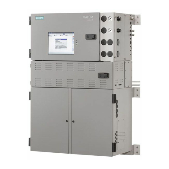
При необходимости установки хроматографа во взрывоопасной зоне, хроматограф может выполняться в специальном взрывозащищенном исполнении с соответствующей маркировкой, указанной в таблице 1. Взрывозащита обеспечивается как продувкой блока электроники хроматографа воздухом КИП под избыточным давлением, так и взрывозащищенным исполнением отдельных узлов и компонентов (детекторов, нагревателей, электромагнитных клапанов и т.п.). Внешний вид хроматографов приведен на рисунках 1 и 2.
|
Исполнение хроматографа |
Ех-маркировка |
Соответствуют требованиям стандартов |
|
Maxum II Исполнение 1 |
1Ex d e py IIB+H2 T4…T1 Gb X или 1Ex d e px py IIB+H2 T4…T1 Gb X или 1Ex d e ib px py IIB+H2 T4.T1 Gb X или 1Ex d e m px IIB+H2 T4…T1 Gb X или 1Ex d e ib m px IIB+H2 T4.T1 Gb X |
ГОСТ Р МЭК 60079-0-2011, ГОСТ IEC 60079-1-2011, ГОСТ IEC 60079-2-2011, ГОСТ Р МЭК 60079-7-2012, ГОСТ Р МЭК 60079-11-2010, ГОСТ Р МЭК 60079-18-2012 |
|
Maxum II Исполнение 2 |
1Ex py nA nC ib IIC T4 Gb X или 1Ex px ib IIC T4 Gb X |
ГОСТ Р МЭК 60079-0-2011, ГОСТ IEC 60079-2-2011, ГОСТ Р МЭК 60079-11-2010, ГОСТ Р МЭК 60079-15-2010 |
Место нанесения знака поверки
Программное обеспечение
Хроматографы оснащены встроенным ПО, работающим под управлением операционной системой Windows CE, которое управляет работой прибора и отображает, обрабатывает и хранит полученные данные. Идентификационные данные ПО приведены в таблице 2.
Таблица 2
|
Идентификационные данные (признаки) |
Значение |
|
Идентификационное наименование ПО |
САС_8И4_МАХиМ |
|
Номер версии (идентификационный номер) ПО |
не ниже 3.00.00. |
Все ПО является метрологически значимым и выполняет следующие функции:
■ управление прибором;
■ настройка режимов работы прибора;
■ получение хроматограмм;
■ обработка и хранение результатов измерений
■ проведение калибровки прибора
■ проведение диагностических проверок прибора и отдельных его блоков; Уровень защиты ПО от непреднамеренных и преднамеренных изменений соответствует
уровню «средний» по Р 50.2.077-2014. Влияние ПО на метрологические характеристики учтено при их нормировании.
Технические характеристики
1 Предел детектирования и предельное допускаемое значение относительного изменения выходного сигнала за цикл измерений 48 часов (в зависимости от типа детектора):
|
Детек тор |
Предел детектирования, не более |
Контрольное вещество |
Предельное допускаемое значение относительного изменения выходного сигнала за цикл измерений 48 часов (по площади пика), % |
|
ДТП |
0,5 • 10-10 г/см3 |
Бензол1 |
±2,0 |
|
Пропан |
|||
|
ПИД |
0,5 10-13 г/с |
Бензол1 |
±2,0 |
|
110-12 г/с |
Пропан |
||
|
ПФД |
3 10-12 г/c (по сере) |
Сера меркаптановая1 |
±4,0 |
|
Сероводород |
2 Относительное СКО выходного сигнала (в зависимости от детектора), %, не более:
|
Детектор |
По времени удерживания |
По высоте пика |
По площади пика |
|
ДТП |
1,0 |
2,0 |
2,0 |
|
ПИД |
1,0 |
2,0 |
2,0 |
|
ПФД |
2,0 |
4,0 |
4,0 |
3. Напряжение сетевого питания частотой 50±1 Гц, В 220 22-зз
4. Потребляемая мощность, В А, не более: 2000
5. Средний срок службы, лет, не менее 8
6. Наработка на отказ, ч, не менее
7. Габаритные размеры (ДхШхВ), мм, не более: -исполнение 1 -исполнение 2
16000
662x411x1010
662x411x683
8. Масса, кг, не менее: -исполнение 1 -исполнение 2
77
60
9. Условия эксплуатации:
о/~’
от -18 до +50 80
от 84 до 106
-диапазон температур окружающего воздуха, С -диапазон относительной влажности окружающего воздуха (при 25 оС), %, не более -диапазон атмосферного давления, кПа
Знак утверждения типа
наносится на титульный лист руководства по эксплуатации методом компьютерной графики и на левую боковую панель корпуса хроматографа в виде наклейки.
Комплектность
определяется заказом и отражается в спецификации.
Основной комплект включает:
— хроматограф;
— руководство по эксплуатации;
— методику поверки МП-242-1896-2015.
Поверка
осуществляется по документу МП-242-1896-2015 «Хроматографы газовые промышленные Maxum edition II. Методика поверки», утвержденному ГЦИ СИ ФГУП «ВНИИМ им. Д.И.Менделеева» 05.07.2015 года.
Основные средства поверки: стандартный образец массовой и объемной доли бензола в нефтепродуктах ГСО 10185-2013, стандартный образец содержания меркаптановой серы в нефтепродуктах ГСО 8418-2003. Стандартные образцы — поверочные газовые смеси: 103222013 (пропан/гелий), ГСО 10538-2014 (сероводород/ метилмеркаптан/ этилмеркаптан/азот) или ГСО 8529-2004 (сероводород/азот) или аналогичные по составу и метрологическим характеристикам ГСО.
Сведения о методах измерений
приведены в документе «Хроматографы газовые промышленные Maxum edition II. Руководство по эксплуатации»
Нормативные и технические документы, устанавливающие требования к хроматографам газовым промышленным Maxum edition II
Техническая документация фирмы-изготовителя.
Siemens Maxum II: Available Instructions
Note for Owners:
Guidesimo.com webproject is not a service center of Siemens trademark and does not carries out works for diagnosis and repair of faulty Siemens Maxum II equipment. For quality services, please contact an official service center of Siemens company. On our website you can read and download documentation for your Siemens Maxum II device for free and familiarize yourself with the technical specifications of device.
-
Agilent Technologies Varian CP-8400
Varian, Inc. 2700 Mitchell Drive Walnut Creek, CA 94598-1675/USA Varian, Inc. 2003 Printed in the Netherlands 03-914852-00:Rev. 4.1 CP-8400 AutoSampler and CP-8410 AutoInjector Operator’s Manual …
Varian CP-8400 Laboratory Equipment, 62
-
Leica CM3050 S
Leica CM3050SCryostat Instructions for UseEnglishOrder No.: 14044380101 — Revision GAlways keep this manual with the instrument.Read carefully before working with the instrument.Version 2.0, Revision G — 11/2017 …
CM3050 S Laboratory Equipment, 86
-
Munchkin Steam Guard
CCD-0053-001 REV 2IF THE SUPPLY CORD IS DAMAGED, IT MUST BE REPLACED BY A SPECIAL CORD OR ASSEMBLY AVAILABLE FROM THE MANUFACTURER OR ITS SERVICE AGENT.SI LE CORDON D’ALIMENTATION EST ENDOMMAGÉ, IL DOIT ÊTRE REPLACÉ PAR UN CORDON SPÉCIAL POUVANT ÊTRE OBTENU AUPRÈS DU FABRICANT OU D’UN RÉPARATEUR AGRÉÉ. …
Steam Guard Laboratory Equipment, 8
-
Velp Scientifica F201A0500
1 Instruction Manual Manuale di istruzioni Manuel d’instructions Manual de instrucciones Bedienungsanleitung CONTROLLER Advance F201A0500 General Information / Informazioni Generali / Informations Générales / Información General / Allgemeine Hinweise Before using the unit, please read the following instruction manual carefully. Prima dell’utilizzo dello strumento si raccomanda d …
F201A0500 Laboratory Equipment, 36
-
REITEL RETOCAST T
Operating Instructions LABORATORY EQUIPMENTIN STAINLESS STEEL RETOCAST T REITEL Feinwerktechnik GmbH Senfdamm 20 — 49152 Bad Essen Phone: +49(0)5472-9432-0 — Fax: +49(0)5472-9432-40 http://www.reitel.com — [email protected] …
RETOCAST T Laboratory Equipment, 28
-
Bio-Works BabyBio S
IN 45 100 010 • AA • 1 / 12 INSTRUCTION IN 45 100 010 BabyBio S BabyBio Q BabyBio DEAE BabyBio™ S, BabyBio Q and BabyBio DEAE are ready-to-use ion exchange chromatography columns for easy and convenient purification of proteins, peptides and oligonucleotides, by utilizing the difference in these molecules surface charge. BabyBio S works as a strong cation exchanger, BabyBio Q a …
BabyBio S Laboratory Equipment, 12
-
Drinkpod 1000 Pro Series
Use & Care GuideEnglish 1000 Pro Series Countertop Purier·Dispenser·SterilizerModel: DP1000(B)Customer Assistance 1-844-374-6576www.drinkpod.comDrinkpod and the Drinkpod logo are the registeredtrademarks of Drinkpod, LLC. All Rights Reserved. …
1000 Pro Series Laboratory Equipment, 27
-
SciCan statim 5000 G4
95-112505 Rev. 4.0 Copyright 2011 SciCan Ltd . All rights reserved.STATim 2000/5000 G4CASSETTE AUTOCLAVE™• Setting Up and Using Your Web Portal• Paramétrage et utilisation de votre portail Web• Einrichtung und Verwendung Ihres Web-Portals• Impostazione e uso del Vostro portale web• Conguración y uso de su portal …
statim 5000 G4 Laboratory Equipment, 56
Popular Laboratory Equipment User Guides:
Table of Contents for Siemens Maxum II:
-
Compare Airflow Loss Shutdown PECM Air Bath Oven High-Wattage Heater Analog SSR Pair Air Pressure Switch Digital Temp Control, Temp Limit, Overtemp RTDs Temp Setpoint Modules PWM I 2 C Temperature Control Airflow Loss Shutdown Heater AC Line SSRa SSRb SYSCON Figure 2-9 PECM Heater Control Functions Each circuit consists of two series-connected solid-state relays. One of these relays controls the 1400-Watt AC heater to maintain the set point
-
2.10.3 Replacement Procedures Overview Replacing the color touchscreen panel requires removal and disassembly of the door. WARNING Follow Safety Precautions. Failure to follow proper procedures may result in equipment damage, personal injury or death. Full safety precautions must be followed throughout all sections of this procedure to prevent possible injury, equipment damage, or death. Verify that the area is clear of flammable gases and vapors and that appropriate authorization is obtained to do the
-
11.Ensure the correct fuses are in the correct positions, as shown in PECM AC Power Distribution illustration. 12.When the procedure is completed, follow the steps in the General Analyzer Startup Procedure . 2.3 System Controller Version 2.1 (SYSCON2.1) 2.3.1 Description The System Controller (SYSCON2.1) is a combination of two interconnected boards that together function as the control processor and motherboard for the Maxum analyzer. The SYSCON2.1 consists of two boards, the Communication and Analytical Control
-
2.3.3.2 CAC3 Status Indicator LEDs The CAC3 is equipped with several LEDs that communicate useful information about the operating status of the CAC3. Link Acknowledge LED4 LED5 LED7 LED1 LED2 LED3 Link Status Figure 2-13 CAC3 LED Locations LED1 Debug LED1 Green – On during normal operation. LED2 Debug LED2 Green – On during normal operation. Off during bootload. LED3 Power Good Green – Power to CAC3 is functional.
-
2.7 Solid State Relay Module The Solid State Relay (SSR) Module is made up of two pairs of high wattage heater relays that are used for controlling the oven air bath heaters. One pair controls ABH1 and the other ABH2. Each pair of relays controls Temperature Limit and Oven Temperature shut down. If the over temperature limit is exceeded, the power to the air bath heater is shutdown. Two different configurations of SSR are available, the SSR and the
-
2.3.4 Maintenance Overview Board Replacement A failure in the SYSCON2.1 will generally interrupt communication between the GCP networkbased software and the detectors. A simplified view of the system is shown below. CAC3 CAN RS485 RS232 Digital Communication DC Supply AC Supply Analyzers GCP Ethernet Ethernet Switch (optional) I/O Boards (I 2 C) 120/240VAC 120/240VAC 120/240VAC 24VDC Heaters 24 V Supply PECM SSR Board 24VDC 24VDC I
-
Vapor or High Pres‐ sure Liquid Samples Model 20 The air-pressure actuated, diaphragm valve provides uniform sample volume, low internal volume, high pressure up to 1500 psi, 10350 kPa, fast switching (millisec‐ onds), reliability, and durability. It functions equally well as a liquid or vapor sample valve, column switching valve, or column back flush valve. Liquid Sample LIV The liquid injection valve can be used to automatically inject a constant quantity of liquid sample followed by fast, complete vaporization. Small gas quantities can also be injec
-
Note Verify proper position of line-voltage selector switch and fuse value. Incorrect settings can damage the equipment. See the information packet that was shipped with the analyzer for information on the individual analyzer. Electronic Compartment Component Descriptions and Maintenance Procedures 2.1 Power Supplies Maxum II Reference Manual Manual, 7/2017, 2000596-001 17
-
8. Lift the unit up and out of the enclosure and place on an ESD-safe work surface. 9. Remove the two mounting screws near the upper corners and remove the old unit from the DPM cage. Configuring the New IS-TCD3 DPM Set the location ID switch and reference-selector switches on the replacement unit to match those on the unit being removed. Note The newer units use slide switches in place of the 2-pos
-
Overview of DPM Functions The Base 3 Detector Personality Module (DPM) combines these functions in a single module: Including Mezzanine Modules FID Input from detector via mezzanine module Ignite signal / glow-plug output Range-select output 300-V bias output Flame-sense input (used in Maxum I analyzers only) FPD Input from detector via mezzanine module Ignite signal / glow-plug output Range-select output Enable signal output 300V bias output Flame-sense input (used in Maxum I analyzers
-
Digital inputs ● Optically coupled with a common for all inputs. ● Self powered floating-contact input, or configurable for sinking or sourcing current. ● Sourcing current mode: 24 V internal isolated supply, with positive terminal of supply at common. ● Sinking current mode: 5 V internal isolated supply, with negative terminal of supply at common. Digital outputs Floating double-throw contacts, maximum contact load rating 1 A at 30 V (AC or DC). External diode shunt suppression should be used for induct
-
2.4.4 Analog and Digital IO Board………………………………………………………………………………………60 2.5 Detector Personality Modules……………………………………………………………………………………61 2.5.1 DPM Types……………………………………………………………………………………………………..
-
Electronic Compartment Component Descriptions and Maintenance Procedures 2.10 Color Touchscreen Maxum II Reference Manual 92 Manual, 7/2017, 2000596-001
-
2.4.1 IO Card Common Features Available IO Boards The newest version of IO board communicates over the I 2 C bus. The I 2 C IO boards are the type available for new installation. ● Analog IO board (AIO_I2C, Part Number A5E02486267001): has 8 analog output channels, 8 analog input channels, and 2 digital input channels ● Digital IO board (DIO_I2C, Part Number A5E02486268001): has 8 digital outputs and 6 digital inputs ● Analog and Digital IO board (ADIO_I2C, Part Number A5E02359491001): has 4 digital outputs
-
Install wire tie for the LCD connector through hole adjacent to the cutout. Install wire tie on the lower TIB standoff near the intrinsic safety ground lugs. Install wire tie for backlight connector through small hole at the corner of the panel plate. Figure 2-49 Wire Tie Installation Detail Electronic Compartment Component Descriptions and Maintenance Procedures 2.10 Color Touchscreen Maxum II Refe
-
Analyzer Overview 1 1.1 Introduction The Maxum edition II system, also called the “Maxum II”, represents a significant advance in process chromatography. The Maxum II combines the best of the Siemens Advance Maxum and PGC 302 gas chromatographs into a single platform analyzer. From oven and electronic components to software and communication networks, the system is modular. Pre-configured application modules are available for many common measurements. A Maxum II system offers a wide range of detector modules including Thermal Conductivity,
Questions, Opinions and Exploitation Impressions:
You can ask a question, express your opinion or share our experience of Siemens Maxum II device using right now.
Download Manual of Siemens Maxum II Laboratory Equipment, Measuring Instruments for Free or View it Online on All-Guides.com.

1

2

3

4

5

6

7

8

9

10

11

12

13

14

15

16

17

18

19

20

21

22

23

24

25

26

27

28

29

30

31

32

33

34

35

36

37

38

39

40

41

42

43

44

45

46

47

48

49

50

51

52

53

54

55

56

57

58

59

60

61

62

63

64

65

66

67

68

69

70

71

72

73

74

75

76

77

78

79

80

81

82

83

84

85

86

PD PA AP
Maxum edition II Analyzer General
Maintenance
Manual
General Analyzer Functions, Troubleshooting, and
Maintenance for Maxum II Gas Chromatographs. The
information in this manual supercedes the applicable
topics in previous manuals.
August 2018
A5E42019842001
Introduction
1
Safety notes
2
System Functions
3
General Maintenance and
Troubleshooting
4
Appendix A — Contact
Information
A
Siemens Maxum II Other PDF User Guides and Manuals for Free Download: Found (3) Manuals for Siemens Maxum II Device Model (Manual , Reference Manual)
More Measuring Instruments Device Models:
-
Gima
BC401
Gima S.p.A. — Via Marconi, 1 — 20060 Gessate (MI) ItalyItalia: tel. 199 400 401 — fax 199 400 403Export: tel. +39 02 953854209/221/225 — fax +39 02 [email protected] — [email protected] URINEURINE ANALYZERANALYSEUR D’URINESANALIZADOR DE ORINA Manuale d’uso — User manualNotic …
BC401 Measuring Instruments, 92
-
CORNING
OV-1000
1Quick Reference Manual OV-1000 Issue 1.1 March 2007 Note!! Please read before proceeding. Please print “Release Notes” from the installation CD before installing software and follow instructions closely. Failure to do so will cause communication issues between OTDR and computer. …
OV-1000 Measuring Instruments, 29
-
Det-Tronics
X9800
Instructions 95-8554IR Flame DetectorX9800Detector Electronics Corporation6901 West 110th Street •Minneapolis, Minnesota 55438 USATel: 952.941.5665 or 800.765.3473 •Fax: 952.829.87504/03 95-8554 …
X9800 Smoke Alarm, 20
-
ABB
ProcessMaster FEP630 series
— ABB MEASUREMENT & ANALYTICS | OPERATING INSTRUCTION ProcessMaster FEP630, HygienicMaster FEH630 Electromagnetic flowmeter — ABB Limited Measurement & Analytics Howard Road, St. Neots Cambridgeshire, PE19 8EU UK Tel: +44 (0)870 600 6122 Fax: +44 (0)1480 213 339 Email: [email protected] ABB Au …
ProcessMaster FEP630 series Measuring Instruments, 152
Recommended Documentation:
Table of Contents for Siemens Maxum II:
-
# Text Description Action 711 + Database: %3 System error Contact Customer Support. 712 ! %6 Start Ver: %3 — %4 on %5 SYSCON has been reset. Informational message. No action necessary. 713 + System backed up System error Contact Customer Support. 714 + All alarms cleared System error Contact Customer Support. 715 + Database Build System error Contact Customer Support. 716 ? DB: Invalid Sourcekey or SourceAttribute for Stat‐ Mon table: ID %3 Occurs when StatMon table is not prop‐ erly configured. C
-
Table of contents 1 Introduction…………………………………………………………………………………………………………………………………5 1.1 Analyzer Specific Documents……………………………………………………………………………………..5 2 Safety notes………………………………………………………….
-
# Text Description Action 2571 ? I2C FPGA Recovery Failed on %4 SNECON I2C driver: SNECON firmware internal error (SNECON revision 3.0 hardware only). Reset the analyzer. Reload the SNECON OS software. Replace the SNECON. 2572 ? I2C FPGA Read in pro‐ gress not set after header on %4 SNECON I2C driver: SNECON firmware internal error (SNECON revision 3.0 hardware only). Reset the analyzer. Reload the SNECON OS software. R
-
4.6.12 Alarms 2217 — 2306 DPM FID GCP Alarm Descriptions 2217 — 2306 DPM Errors The following tables list the alarm number (#), type (+ information, ? warning, ! error) alarm text, description, and actions. # Text Description Action 2217 ! Balance Hardware Failure FID L %5 on %4 System error Contact Customer Support. 2218 ! Balance Hardware Failure FID U %5 on %4 System error Contact Customer Support. 2219, 2220 ! A/D Failure [FID; TCD] %5 on %4 DPM Detector PIC: Set when the corre‐ sponding Analog to Digital
-
Figure 3-1 Example Applet 3.2 Functions Overview This section provides an operational overview of the real-time functional tasks of the Maxum II. ● Startup Tasks – Applying Power – Valid Database – Oven Temperature – Cycle Control Flag ● Timed Event Scheduling – Time-Of-Day Clock – Schedule of Events • Frequency Events ● Analysis Cycle Clock – Accessing System Controller – Analysis Cycle Clock – SYSCON Cycle Clock – Valve Events ● Manual Operations via User Interface Startup Tasks On start-up, when primary AC power is applied to
-
# Text Description Action 425 ! EZChrom Method Verifica‐ tion failed, code %3 The method was successfully downloa‐ ded from the SYSCON to the EMSNE but failed an integrity verification test. The method is likely corrupted or may contain a feature which is not supported. Code values are listed below: 0: Unknown error, the method is likely corrupt. 1: Invalid Method Binary, the method is likely corrupt. 10: Invalid Cycle Lag time. The Cycle Start valu
-
General Maintenance and Troubleshooting 4.6 Alarm Codes, Descriptions, and Suggested Actions Maxum edition II Analyzer General Maintenance 82 Manual, August 2018, A5E42019842001
-
# Text Description Action 3764 ? Timeout SCL on %4 SNECON PICs: An I2C message trans‐ action failed because the I2C clock was stretched beyond the allowed timeout pe‐ riod specified in the configuration. A mod‐ ule may be malfunctioning. Contact Customer Support. 3765 ? Timeout SDA on %4 SNECON PICs: An I2C message trans‐ action failed because the I2C data line was held beyond the allowed timeout pe‐ riod specified in the configuration. A mod‐ ule may be malfunc
-
4.3 General Analyzer Shutdown Procedure Back Up the Database If a current database has not been saved, first save a database to a remote device to provide a potential method of reloading if a CAC3 has been replaced or an earlier database needs to be restored to the analyzer. Generally, a database reload will not be needed, though in some cases this may be required. 1. Put the Maxum II in Hold and wait for the cycle to complete. This will provide the qu
-
# Text Description Action 1084 + I2C Timeout on %4 All PICs: An I2C communication timeout timer has expired. The timer is reset after each successful character processed. Only an addressed module may gener‐ ate a timeout. The timeout can occur on incoming and outgoing characters. Contact Customer Support. 1085 + I2C Read Past End on %4 All PICs: The I2C communication master did not stop reading after the complete response had been sent. Contact Customer Support. 1086 + I2C Buffer
-
Description Color and Meaning LED10 Heartbeat Green – Flashes once for each heartbeat message transmitted. This LED will flash once every 1.5 seconds for each active CAN card LED11 Fault Red – On when an error state is detected on the CAN bus hardware PCI Slot LEDs Located between PCI slots Description Color and Meaning LED14 Slot 0 Fault Red – Overcurrent or thermal shutdown on PCI slot 0 LED13 Slot 1 Fault Red – Overcurrent or thermal shutdown
Questions, Opinions and Exploitation Impressions:
You can ask a question, express your opinion or share our experience of Siemens Maxum II device using right now.
Download or browse on-line these Manual for Siemens Maxum II Laboratory Equipment, Measuring Instruments.
More Manuals:
In case you failed to obtain relevant information in this document, please, look through related operating manuals and user instructions for Siemens Maxum II.
Just click one of the links below to go to the selected manual:


Summary of Contents:
 |
[Page 1] Siemens Maxum II Maxum II PD PA AP Maxum edition II Analyzer General Maintenance Manual General Analyzer Functions, Troubleshooting, and Maintenance for Maxum II Gas Chromatographs. The information in this manual supercedes the applicable topics in previous man… |
 |
[Page 2] Siemens Maxum II Legal information Warning notice system This manual contains notices you have to observe in order to ensure your personal safety, as well as to prevent damage to property. The notices referring to your personal safety are highlighted in the manual b… |
 |
[Page 3] Siemens Maxum II Table of contents 1 Introduction…………………………………………………………………………………………………………………………………5 1.1 Analyzer Specific Documents………………………………….. |
 |
[Page 4] Siemens Maxum II 4.6.15 Alarms 3117 — 3204 EPC………………………………………………………………………………………….69 4.6.16 Alarms 3401 — 3454 TFTP……………………………………………………………………………. |
 |
[Page 5] Siemens Maxum II Introduction 1 This manual provides maintenance information common to various Maxum Edition II Gas Chromatograph models. 1.1 Analyzer Specific Documents Included with each analyzer is a custom documentation-drawing package. This package provides d… |
 |
[Page 6] Siemens Maxum II Introduction 1.1 Analyzer Specific Documents Maxum edition II Analyzer General Maintenance 6 Manual, August 2018, A5E42019842001 |
 |
[Page 7] Siemens Maxum II Safety notes 2 Maxum II Analyzers have varying levels of certification for operating in hazardous environments. See the Maxum II Explosion Protection Safety Standards Manual (A5E02220442001), and the Maxum edition II Installation Manual (200059… |
 |
[Page 8] Siemens Maxum II 2.2 Qualified Personnel Only suitably qualified personnel may operate or perform maintenance on the Maxum II. For the purposes of safety, qualified personnel are defined as follows: ● Those who have been appropriately trained for the tasks which t… |
 |
[Page 9] Siemens Maxum II System Functions 3 3.1 Chromatography Overview Gas Chromatograph Terminology The following are some of the terms that are used in this manual. Application: The supporting hardware and software required to perform the analysis. Supporting hardware co… |
 |
[Page 10] Siemens Maxum II Figure 3-1 Example Applet 3.2 Functions Overview This section provides an operational overview of the real-time functional tasks of the Maxum II. ● Startup Tasks – Applying Power – Valid Database – Oven Temperature – Cycle Control Flag ●… |
 |
[Page 11] Siemens Maxum II Self Test After the self-test, the following conditions occur: ● Installed hardware is initialized. ● Interrupts are enabled. ● Oven temperatures and carrier pressure default set points are output. ● Analog input system(s), associated with de… |
 |
[Page 12] Siemens Maxum II If a calibration is scheduled, it is put in queue. The calibration then initiates after completion of the current cycle, and when the appropriate time has passed for the calibration blend to flow through the sampling valve. If shift average reports… |
 |
[Page 13] Siemens Maxum II Manual Operations Manually controlled functions can be initiated through the color touchscreen. A manually- controlled event can occur asynchronously with any event and control some of the analyzer operations. Controlled items include: ● Activatio… |
 |
[Page 14] Siemens Maxum II FPD DPM (A/D) SYSCON SNE Software Moule GCP I 2 C Network DPM (A/D) Electronic Pressure Control Module Solenoid Valve Control Module Temperature Control Oven Heater Control Electronics Enclosure DPM (A/D) FID Detector Compartment (Mezannine) Oven Sam… |
 |
[Page 15] Siemens Maxum II Sample Valve The type of sample valve used in a Maxum II is application dependent. Five primary types of sample valves are available. ● The first is the 10-port Model 50 valve that is designed for vapor sample only. ● The second is the Model 1… |
 |
[Page 16] Siemens Maxum II Electronic Pressure Control The carrier gas pressure that is used to push the sample through the columns is controlled by an Electronic Pressure Control Module (EPCM) or in some applications by mechanical regulators. The EPCM is mounted on manifold… |
 |
[Page 17] Siemens Maxum II The original SYSCON consists of a single controller board. The newest version of SYSCON, called SYSCON2, is a base SIB (SYSCON Interface Board) with an attached CAC3 (Communication and Control board). The SYSCON combines all data results and perfor… |
 |
[Page 18] Siemens Maxum II Module Addressing The Maxum II modules located in the electronic compartment have their own physical address and communicate via the I 2 C Internal Bus, shown in the diagram below. Address information is contained in the SYSCON database and identif… |
 |
[Page 19] Siemens Maxum II General Maintenance and Troubleshooting 4 4.1 Analyzer Status Indicators 4.1.1 Operator Controls Color Touchscreen The color touchscreen displays all mainte‐ nance functions and data in a graphical dis‐ play. In addition it can also display both … |
 |
[Page 20] Siemens Maxum II Workstation The Maxum II uses a PC based network workstation for programming and data processing. Analyzers can be program‐ med and monitored from a single location, and, like the color touchscreen, the work‐ station includes graphical display… |
 |
[Page 21] Siemens Maxum II 4.1.2 LED States Inside the Electronics Cabinet 4.1.2.1 Base3DPM Status Indicator LEDs Normal Fault Warning Power Active Heater 2 Temp Limit Overtemp Flameout Ignite Alternate Range Power Active Heater 1 Temp Limit Overtemp Figure 4-1 Base3DPM Statu… |
 |
[Page 22] Siemens Maxum II 4.1.2.2 SIB3 LEDs LED Locations The SIB3 has several LEDs that indicate useful information about the operating status of various interfaces. I 2 C-Pullup Active LEDs 3 2 1 0 PCI Slot LEDs Reset I/O Connector DI Mode Switch (Set to Mode 2) CAN Bridg… |
 |
[Page 23] Siemens Maxum II Power LEDs Located at the back of the board near the RJ 45 connector Description Color and Meaning Power Green – 3.3V power is available. Should be on at all times Power Bad Red – Power is faulty or SYSCON hardware reset switch is being pressed C… |
 |
[Page 24] Siemens Maxum II Description Color and Meaning LED10 Heartbeat Green – Flashes once for each heartbeat message transmitted. This LED will flash once every 1.5 seconds for each active CAN card LED11 Fault Red – On when an error state is detected on the CAN bus ha… |
 |
[Page 25] Siemens Maxum II 4.1.2.3 PECM LEDs The LEDs on the PECM board can help with troubleshooting problems. There are two sets of LEDs: one on each side of the front board as shown in the diagram to the right. The bottom set of three LEDs is the same as used on other boa… |
 |
[Page 26] Siemens Maxum II 4.1.2.4 Modular Oven Model PECM-DC LED Locations LED Status Indicators The PECM-DC LED locations are shown below. 1RUPDO )DXOW :DUQLQJ +HDWHU2Q 2YHUWHPS +HDWHU6KRUW 4.2 Leak Testing A gas chromatograph is a complex device with many gas fitting… |
 |
[Page 27] Siemens Maxum II 4.3 General Analyzer Shutdown Procedure Back Up the Database If a current database has not been saved, first save a database to a remote device to provide a potential method of reloading if a CAC3 has been replaced or an earlier database needs to b… |
 |
[Page 28] Siemens Maxum II 4.4.1 Procedure Following is the procedure for safe startup of the Maxum II. 1. Verify that AC power is turned off at main power feed lines. All indicator lights should be off. 2. Verify that the analyzer has been mounted and installed correctly. 3…. |
 |
[Page 29] Siemens Maxum II 11. Turn on the fast purge switch and allow fast purge air to flow for at least 8 minutes. Flow of fast purge air can be verified because of the louder sound of the air flow. The fast purge relief valve opens slightly and the air can be heard as it… |
 |
[Page 30] Siemens Maxum II 4.5 Accessing the Bootloader Accessing the Bootloader to Set the Network Address This procedure is needed when a CAC3 is replaced, when the memory backup battery is removed, or when the CAC3 is removed from a CIM or SIB3. In this procedure, the term… |
 |
[Page 31] Siemens Maxum II 4.6 Alarm Codes, Descriptions, and Suggested Actions 4.6.1 Alarms 301 — 324 GCP Alarm Descriptions 301 — 324 The following tables list the alarm number (#), type (+ information, ? warning, ! error) alarm text, description, and actions. # Text Desc… |
 |
[Page 32] Siemens Maxum II # Text Description Action 310 ? External Message: Unit not known for %3 GC is trying to communicate with an un‐ known unit on the Advance DataHiway. Wait 10 minutes to see if this condition will correct itself. If it does not, verify that the … |
 |
[Page 33] Siemens Maxum II 4.6.2 Alarms 330 through 359 SNE Communication GCP Alarm Descriptions 330 — 359 The following tables list the alarm number (#), type (+ information, ? warning, ! error) alarm text, description, and actions. # Text Description Action 331 ! Run Met… |
 |
[Page 34] Siemens Maxum II # Text Description Action 343 ! SNE %3 Method %4 Load — Invalid Mode Invalid run/hold sent to SNE. Reset SYSCON or try placing applica‐ tion in run. 344 ! SNE %3 Method %4 status — unknown error %5 Unknown error from SNE method status. Reset SN… |
 |
[Page 35] Siemens Maxum II # Text Description Action 358 ! SNE Invalid I/O Write from SNE on %4 , command %5 This should only occur if the SNE has an old software version or the messages be‐ tween the SNE and SYSCON have been corrupted. Check the SNE and SYSCON software… |
 |
[Page 36] Siemens Maxum II # Text Description Action 371 ! Invalid channel acquisition overlap on %3 Two channels referencing the same hardware detector are scheduled to ac‐ quire at the same time. If multiple application detector channels are assigned to the same hardw… |
 |
[Page 37] Siemens Maxum II # Text Description Action 388 ! Acquisition time greater than cycle length on chan‐ nel %3 Start and stop acquisition times for a de‐ tector exceeded the method cycle length. Decrease acquisition time or increase cycle method time. 389 ! Inva… |
 |
[Page 38] Siemens Maxum II # Text Description Action 403 ! Configured Detector %3 Balance Failure Balance Failure from an Advance+ de‐ tector. Check sys_detector_cfg configuration. 404 ? All Methods must be in Hold before Configuring Detectors All methods must be in hol… |
 |
[Page 39] Siemens Maxum II # Text Description Action 425 ! EZChrom Method Verifica‐ tion failed, code %3 The method was successfully downloa‐ ded from the SYSCON to the EMSNE but failed an integrity verification test. The method is likely corrupted or may contain a… |
 |
[Page 40] Siemens Maxum II # Text Description Action 427 + Detector simulation activa‐ ted The detector data reported by the DPM is from a simulation chromatogram read from the EZChrom trace binary and not from actual data acquired by the DPM. This is normal when runni… |
 |
[Page 41] Siemens Maxum II # Text Description Action 511 ! Program Failed event # %3 %4 Error running MaxBasic program. Check message and program. If this program was written by Siemens, con‐ tact Customer Support. 512 ? Program execution cancel‐ led: event # %3 Cancel… |
 |
[Page 42] Siemens Maxum II # Text Description Action 676 ! Database: delay limit ex‐ ceeded on stream %3 Temperature or pressure wait set in the method has been exceeded. Check temp or press controller. Check wait_delta and maxwait in tem‐ perature or pressure controll… |
 |
[Page 43] Siemens Maxum II # Text Description Action 698 ? NAU %3 not available for communication 1. No analyzer reference in host table for Maxum Modbus 2. Cannot open connection to remote an‐ alyzer for Maxum Modbus or remote I/O. This is a sometimes-temporary error … |
 |
[Page 44] Siemens Maxum II # Text Description Action 711 + Database: %3 System error Contact Customer Support. 712 ! %6 Start Ver: %3 — %4 on %5 SYSCON has been reset. Informational message. No action necessary. 713 + System backed up System error Contact Customer Support…. |
 |
[Page 45] Siemens Maxum II # Text Description Action 732 ! IO: underflow or lower fail‐ safe condition detected for %3 The firmware is reporting an under-range error for analog NAMUR data types 6 or 8. Check the wiring for the secondary de‐ vice being used. Verify pro… |
 |
[Page 46] Siemens Maxum II # Text Description Action 806 ? Memory Corruption Error from Task %3 An attempt to free a block of memory was unsuccessful because the header was overwritten. The block of memory was not returned to the free pool. 1. Save a fresh copy of the da… |
 |
[Page 47] Siemens Maxum II # Text Description Action 997 + %3 General alarm used for information. Used most often by MaxBasic programs. No action necessary. 998 ? %3 General warning alarm used for informa‐ tion. Used most often by MaxBasic pro‐ grams. Immediately report… |
 |
[Page 48] Siemens Maxum II # Text Description Action 1007 ! Firmware Fault on %4 All PICs: A ‘run-time’ error was detected in the PIC firmware. For example, a timer is turned off at a point where the firmware expects it to be on. The firmware will at‐ tempt to… |
 |
[Page 49] Siemens Maxum II # Text Description Action 1044 ? Board overheating on %4 All PICs: A module temperature greater than the defined maximum operating temperature (default 65°C) has been de‐ tected.Overheating must be corrected as soon as possible to avoid perma… |
 |
[Page 50] Siemens Maxum II # Text Description Action 1084 + I2C Timeout on %4 All PICs: An I2C communication timeout timer has expired. The timer is reset after each successful character processed. Only an addressed module may gener‐ ate a timeout. The timeout can occur… |
 |
[Page 51] Siemens Maxum II # Text Description Action 1091 + I2C Write Before Read on %4 All PICs: An attempt was made to write an I2C message before reading the re‐ sponse from a previous message. This indicates that an attempt was made to do a Slave Write — Repe… |
 |
[Page 52] Siemens Maxum II # Text Description Action 1124 ! Firmware Watchdog on %4 All PICs: The PIC watch dog timer has expired causing a module reset. This flag is always associated with a FIRM‐ WARE_FAULT flag. It can be an indica‐ tion that the I2C clock or data l… |
 |
[Page 53] Siemens Maxum II 4.6.10 Alarms 1617 — 1697 Pecm Errors GCP Alarm Descriptions 1617 — 1697 PECM Errors The following tables list the alarm number (#), type (+ information, ? warning, ! error) alarm text, description, and actions. # Text Description Action 1617 — 1… |
 |
[Page 54] Siemens Maxum II # Text Description Action 1633 — 1638 ! Output error on solenoid valve, [left location, left group; left location, right group; right location, left group; right location, right group; upper location, left group; upper location, right group… |
 |
[Page 55] Siemens Maxum II 4.6.11 Alarms 1917 — 2005 DPM TCD GCP Alarm Descriptions 1917 — 1999 DPM Errors The following tables list the alarm number (#), type (+ information, ? warning, ! error) alarm text, description, and actions. # Text Description Action 1917 ! Balance… |
 |
[Page 56] Siemens Maxum II # Text Description Action 1929 ! Mezzanine-module ID inva‐ lid FID DPM Detector PIC: The mezzanine- module ID value is not supported by this DPM board. More specifically, the module value is pointing to a non-initial‐ ized EEPROM region on… |
 |
[Page 57] Siemens Maxum II # Text Description Action 1965 ? Flame ignition failure TCD DPM Detector PIC: The FID flame could not be lit within the predefined de‐ lay (25 or 60 sec). No other attempt will be made to automatically light the flame until the MANUAL IGNITIO… |
 |
[Page 58] Siemens Maxum II 4.6.12 Alarms 2217 — 2306 DPM FID GCP Alarm Descriptions 2217 — 2306 DPM Errors The following tables list the alarm number (#), type (+ information, ? warning, ! error) alarm text, description, and actions. # Text Description Action 2217 ! Balance… |
 |
[Page 59] Siemens Maxum II # Text Description Action 2229 ! Mezzanine-module ID inva‐ lid FID DPM Detector PIC: The mezzanine- module ID value is not supported by this DPM board. More specifically, the mod‐ ule value is pointing to a non-initialized EEPROM region on th… |
 |
[Page 60] Siemens Maxum II # Text Description Action 2258 ! Balance Failure TCD %5 on %4 FID DPM Detector PIC: A detector bal‐ ance sequence failed because of a hard‐ ware failure or because of an improper configuration or sequence of events. Some possible causes are:… |
 |
[Page 61] Siemens Maxum II # Text Description Action 2266 ? Gain override FID DPM Detector PIC: An external sig‐ nal is applied to the DPM, overriding the DPM gain control. This is a normal situa‐ tion if a signal is connected to the exter‐ nal gain-select connector. … |
 |
[Page 62] Siemens Maxum II 4.6.13 Alarms 2500 — 2577 Access Bus Driver Errors GCP Alarm Descriptions 2500 — 2577 Access Bus Driver Errors The following tables list the alarm number (#), type (+ information, ? warning, ! error) alarm text, description, and actions. # Text De… |
 |
[Page 63] Siemens Maxum II # Text Description Action 2516 ? I2C Invalid Bus on %4 SNECON I2C driver: Invalid I2C bus identification number. Reset the analyzer. 2518 ? I2C Unknown Address Re‐ ceived on %4 SNECON I2C driver: SNECON firmware internal error. Reset the analyz… |
 |
[Page 64] Siemens Maxum II # Text Description Action 2540 ? I2C Message Too Short on %4 SNECON I2C driver: An I2C message received by the SNECON is too short to be valid. Contact Customer Support. 2541 + I2C FPGA Queue Full on %4 SNECON I2C driver: SNECON firmware inter… |
 |
[Page 65] Siemens Maxum II # Text Description Action 2555 ? I2C Internal Error; Block Table full SNECON I2C driver: SNECON firmware internal error (SNECON revision 3.0 hardware only). Reset the analyzer. Reload the SNECON OS software. Replace the SNECON. 2556 ? I2C Not E… |
 |
[Page 66] Siemens Maxum II # Text Description Action 2571 ? I2C FPGA Recovery Failed on %4 SNECON I2C driver: SNECON firmware internal error (SNECON revision 3.0 hardware only). Reset the analyzer. Reload the SNECON OS software. Replace the SNECON. 2572 ? I2C FPGA Read i… |
 |
[Page 67] Siemens Maxum II 4.6.14 Alarms 2817 — 2904 DPM Temperature GCP Alarm Descriptions 2817 — 2904 — DPM Temperature The following tables list the alarm number (#), type (+ information, ? warning, ! error) alarm text, description, and actions. # ! Text Description Action… |
 |
[Page 68] Siemens Maxum II # ! Text Description Action 2901, 2902 ? Deviation [1 — 2] Exceeded on %4 Temperature controller PIC: The meas‐ ured temperature deviation (TEMP_DE‐ VIATION) has exceeded the correspond‐ ing MAX_DEVIATION value. The PID control was not su… |
 |
[Page 69] Siemens Maxum II 4.6.15 Alarms 3117 — 3204 EPC GCP Alarm Descriptions 3117 — 3204 EPC The following tables list the alarm number (#), type (+ information, ? warning, ! error) alarm text, description, and actions. # Text Description Action 3117, 3118 ! Pressure [1… |
 |
[Page 70] Siemens Maxum II # Text Description Action 3163, 3164 ! EPC Shutdown on %4, Channel [1 — 2] The [n] channel of the Electronic Pres‐ sure Control (EPC) was temporarily shut down. This happens when the EPC control valve is fully opened for more than 5s and … |
 |
[Page 71] Siemens Maxum II # Text Description Action 3451 ? TFTP Client Checksum Er‐ ror File loaded had invalid checksum. Verify that loadfile is correct and uncor‐ rupted. 3452 ? TFTP Client Missing End of File Attempt to load truncated file. Verify that loadfile is c… |
 |
[Page 72] Siemens Maxum II 4.6.18 Alarms 3718 — 3804 SNE I/O GCP Alarm Descriptions 3718 — 3804 SNE I/O The following tables list the alarm number (#), type (+ information, ? warning, ! error) alarm text, description, and actions. # Text Description Action 3718 ! FPGA Error… |
 |
[Page 73] Siemens Maxum II # Text Description Action 3757 ? NACK address on %4 SNECON PICs: An I2C message trans‐ action failed after the required number of retries. A cause of this failure was a unacknowledged destination address byte (first byte in the message). �… |
 |
[Page 74] Siemens Maxum II # Text Description Action 3764 ? Timeout SCL on %4 SNECON PICs: An I2C message trans‐ action failed because the I2C clock was stretched beyond the allowed timeout pe‐ riod specified in the configuration. A mod‐ ule may be malfunctioning. Con… |
 |
[Page 75] Siemens Maxum II # Text Description Action 3801 ? Invalid Status Data on %4 SNECON PICs: The content of the status buffer, ‘Status_data’, was invalid and not recognized by the PIC. This may happen if the PIC firmware is out of date relative to the NS4… |
 |
[Page 76] Siemens Maxum II # Text Description Action 4028 ? Detector channel unknown error occurred on %4 Undeterminable error occurred on detec‐ tor channel circuit. This error may also be a secondary error caused by an overflow on an FID DPM. Reset. If error repeats, … |
 |
[Page 77] Siemens Maxum II 4.6.20 Alarms 4217 — 4320 CAN Bridge GCP Alarm Descriptions 4217 — 4320 CAN Bridge The following tables list the alarm number (#), type (+ information, ? warning, ! error) alarm text, description, and actions. # Text Description Action 4217 ! CAN:… |
 |
[Page 78] Siemens Maxum II # Text Description Action 4265 ? CAN: Receive Init Buffer Overflow The CAN bus receive buffer that process‐ es messages from uninitialized CAN cards has overflowed. Initialization will likely fail. Contact Customer Support. 4266 ? CAN: Receive… |
 |
[Page 79] Siemens Maxum II # Text Description Action 4300 + CAN: Unrecognized card This flag is set when an uninitialized card is detected on the bus after the init se‐ quence is complete. The most com‐ mon cause of this condition is a Node/SN list that does not pre… |
 |
[Page 80] Siemens Maxum II # Text Description Action 4601 ? Temperature Deviation Ex‐ ceeded on %4 Advance Adapter Temperature Control‐ ler PIC: The measured temperature de‐ viation (TEMP_DEVIATION) has excee‐ ded the corresponding MAX_DEVIA‐ TION value. The PID co… |
 |
[Page 81] Siemens Maxum II 4.6.22 Alarms 10000 — 11536 MicroSAM GCP Alarm Descriptions — 10000 — 11536 MicroSAM The following tables list the alarm number (#), type (+ information, ? warning, ! error) alarm text, description, and actions. # Text Description Action 10000 ! T… |
 |
[Page 82] Siemens Maxum II General Maintenance and Troubleshooting 4.6 Alarm Codes, Descriptions, and Suggested Actions Maxum edition II Analyzer General Maintenance 82 Manual, August 2018, A5E42019842001 |
 |
[Page 83] Siemens Maxum II Appendix A — Contact Information A Register at the Siemens Industry Online Support (SIOS) website: https://support.industry.siemens.com International USA Siemens AG I IA SC PA PM Process Analytics Oestliche Rheinbrueckenstrasse 50 76187 Karlsruhe Ge… |
 |
[Page 84] Siemens Maxum II Appendix A — Contact Information Maxum edition II Analyzer General Maintenance 84 Manual, August 2018, A5E42019842001 |
 |
[Page 85] Siemens Maxum II Index A Applet, 9 Applet Module, 9 Application, 9 C Columns, 15 D DHCP, 30 E EC, 15 Ethernet IP, 30 F Filament, 16 Flame Ionization, 16 Flame Photometric, 16 I IP address, 30 M Method, 9 P Pulsed Discharge, 16 S Sensor Near Electronics, 12 Sensor Nea… |
 |
[Page 86] Siemens Maxum II Index Maxum edition II Analyzer General Maintenance 86 Manual, August 2018, A5E42019842001 |