- Manuals
- Brands
- MSI Manuals
- Motherboard
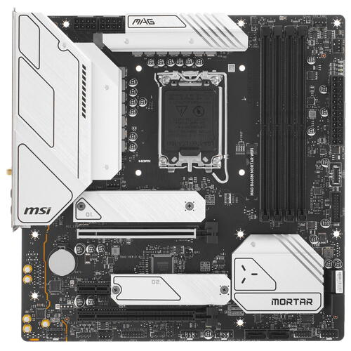
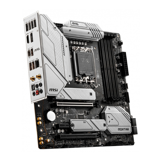
- MAG B660M MORTAR WIFI DDR4
Manuals and User Guides for MSI MAG B660M MORTAR WIFI DDR4. We have 4 MSI MAG B660M MORTAR WIFI DDR4 manuals available for free PDF download: User Manual
MSI MAG B660M MORTAR WIFI DDR4 User Manual (403 pages)
Brand: MSI
|
Category: Motherboard
|
Size: 34.46 MB
Table of Contents
-
English
3
-
Table of Contents
3
-
Quick Start
5
-
Installing DDR4 Memory
9
-
Specifications
17
-
Special Features
21
-
Package Contents
22
-
Back Panel Connectors
23
-
LAN Port LED Status Table
24
-
Audio Jacks Connection
24
-
Installing Antennas
26
-
Overview of Components
27
-
CPU Socket
28
-
DIMM Slots
29
-
PCI_E1~3: Pcie Expansion Slots
30
-
M2_1~2: M.2 Slots (Key M)
31
-
SATA5~8 & SATA_A1~A2: SATA 6Gb/S Connectors
33
-
JAUD1: Front Audio Connector
33
-
JFP1, JFP2: Front Panel Connectors
34
-
JTBT1: Thunderbolt Add-On Card Connector
35
-
JDASH1 : Tuning Controller Connector
35
-
CPU_PWR1~2, ATX_PWR1: Power Connectors
36
-
JCI1: Chassis Intrusion Connector
37
-
JUSB4: USB 3.2 Gen 2 Type-C Connector
38
-
JUSB3: USB 3.2 Gen 1 Connector
38
-
JUSB1~2: USB 2.0 Connectors
39
-
JTPM1: TPM Module Connector
39
-
CPU_FAN1, PUMP_FAN1, SYS_FAN1~4: Fan Connectors
40
-
JBAT1: Clear CMOS (Reset BIOS) Jumper
41
-
BAT1: CMOS Battery
41
-
JRGB1: RGB LED Connector
42
-
JARGB_V2_1~2: A-RAINBOW V2 (ARGB Gen2) LED Connectors
43
-
EZ Debug LED
44
-
Installing OS, Drivers & MSI Center
45
-
MSI Center
47
-
Uefi Bios
48
-
BIOS Setup
49
-
Resetting BIOS
50
-
Updating BIOS
50
-
-
Deutsch
52
-
Schnellstart
54
-
Installation des DDR4-Speichers
58
-
Spezifikationen
66
-
Besondere Funktionen
70
-
Lieferumfang
71
-
Anschlüsse auf der Rückseite
72
-
Audiobuchsen
73
-
LAN Port LED Zustandstabelle
73
-
Antennen Installieren
75
-
Übersicht der Komponenten
76
-
CPU Sockel
77
-
DIMM Steckplätze
78
-
PCI_E1~3: Pcie Erweiterungssteckplätze
79
-
M2_1~2: M.2 Steckplätze (Key M)
80
-
JAUD1: Audioanschluss des Frontpanels
82
-
SATA5~8 & SATA_A1~A2: SATA 6Gb/S Anschlüsse
82
-
JFP1, JFP2: Frontpanel-Anschlüsse
83
-
JDASH1: Tuning Controller-Anschluss
84
-
JTBT1: Anschluss für Thunderbolt-Erweiterungskarte
84
-
CPU_PWR1~2, ATX_PWR1: Stromanschlüsse
85
-
JCI1: Gehäusekontaktanschluss
86
-
JUSB3: USB 3.2 Gen 1 Anschluss
87
-
JUSB4: USB 3.2 Gen 2 Typ-C Anschluss
87
-
JTPM1: TPM Anschluss
88
-
JUSB1~2: USB 2.0 Anschlüsse
88
-
CPU_FAN1, PUMP_FAN1, SYS_FAN1~4: Stromanschlüsse für Lüfter
89
-
BAT1: CMOS-Akku
90
-
JBAT1: Clear CMOS Steckbrücke (Reset BIOS)
90
-
JRGB1: RGB LED Anschluss
91
-
JARGB_V2_1~2: A-RAINBOW V2 (ARGB Gen2) LED Anschlüsee
92
-
Ez Debug Led
93
-
Installation von OS, Treibern & MSI Center
94
-
MSI Center
96
-
Uefi Bios
97
-
BIOS Setup
98
-
Aktualisierung des BIOS
99
-
Reset des BIOS
99
-
-
Français
101
-
Démarrage Rapide
103
-
Installation de la Mémoire DDR4
107
-
Caractéristiques
115
-
Fonctions Spéciales
119
-
Contenu
120
-
Connecteurs de Panneau Arrière
121
-
Connexion des Prises Audio
122
-
Tableau Explicatif de L’état de la LED du Port LAN
122
-
Installation des Antennes
124
-
Vue D’ensemble des Composants
125
-
Socket CPU
126
-
Slots DIMM
127
-
PCI_E1~3 : Slots D’extension Pcie
128
-
M2_1~2 : Slots M.2 (Touche M)
129
-
JAUD1 : Connecteur Audio Avant
131
-
SATA5~8 Et SATA_A1~A2 : Connecteurs SATA 6 Gb/S
131
-
JFP1, JFP2 : Connecteurs de Panneau Avant
132
-
JDASH1 : Connecteur du Contrôleur de Réglages
133
-
JTBT1 : Connecteur de Carte Additionnelle Thunderbolt
133
-
CPU_PWR1~2, ATX_PWR1 : Connecteurs D’alimentation
134
-
JCI1 : Connecteur Intrusion Châssis
135
-
JUSB3 : Connecteur USB 3.2 Gen 1
136
-
JUSB4 : Connecteur USB 3.2 Gen 2 Type-C
136
-
JTPM1 : Connecteur de Module TPM
137
-
JUSB1~2 : Connecteurs USB 2.0
137
-
CPU_FAN1, PUMP_FAN1, SYS_FAN1~4 : Connecteurs de Ventilateur
138
-
BAT1 : Pile CMOS
139
-
JBAT1 : Cavalier Clear CMOS (Réinitialiser Le BIOS)
139
-
JRGB1 : Connecteur LED RGB
140
-
JARGB_V2_1~2 : Connecteurs LED A-RAINBOW V2 (ARGB Gen2)
141
-
EZ Debug LED
142
-
Installer OS, Pilotes Et MSI Center
143
-
MSI Center
145
-
Uefi Bios
146
-
Configuration du BIOS
147
-
Mettre Le BIOS À Jour
148
-
Réinitialiser Le BIOS
148
-
-
Русский
150
-
Краткое Руководство По Установке
152
-
Установка Модуля Памяти DDR4
156
-
Технические Характеристики
164
-
Эксклюзивные Функции
168
-
Комплект Поставки
169
-
Разъемы Задней Панели
170
-
Подключение Аудиоразъемов
171
-
Таблица Состояний Индикатора Порта LAN
171
-
Установка Антенн
173
-
Компоненты Материнской Платы
174
-
Процессорный Сокет
175
-
Слоты DIMM
176
-
PCI_E1~3: Слоты Расширения Pcie
177
-
M2_1~2: Разъемы M.2 (Ключ M)
178
-
JAUD1: Разъем Аудио Передней Панели
180
-
SATA5~8 & SATA_A1~A2: Разъемы SATA 6Гб/С
180
-
JFP1, JFP2: Разъемы Передней Панели
181
-
JDASH1 : Разъем Контроллера Настройки
182
-
JTBT1: Разъем Для Установки Карты Расширения Thunderbolt
182
-
CPU_PWR1~2, ATX_PWR1: Разъемы Питания
183
-
JCI1: Разъем Датчика Открытия Корпуса
184
-
JUSB3: Разъем USB 3.2 Gen 1
185
-
JUSB4: Разъем USB 3.2 Gen 2 Type-C
185
-
JTPM1: Разъем Модуля ТРМ
186
-
JUSB1~2: Разъемы USB 2.0
186
-
CPU_FAN1, PUMP_FAN1, SYS_FAN1~4: Разъемы Вентиляторов
187
-
BAT1: Батарейка CMOS
188
-
JBAT1: Джампер Очистки Данных CMOS (Сброс BIOS)
188
-
JRGB1: Разъем RGB LED
189
-
JARGB_V2_1~2: Разъемы A-RAINBOW V2 (ARGB Gen2) LED
190
-
Индикаторы Отладки EZ
191
-
Установка ОС, Драйверов И MSI Center
192
-
MSI Center
194
-
Uefi Bios
195
-
Настройка BIOS
196
-
Обновление BIOS
197
-
Сброс BIOS
197
-
-
日本語
199
-
クイックスタート
201
-
Ddr4メモリの取り付け
205
-
Msi独自の機能
217
-
パッケージの内容
218
-
バックパネルコネクター
219
-
LanポートLed状態表
220
-
オーディオジャックの接続
220
-
アンテナの取り付け
222
-
コンポーネントの概要
223
-
Cpuソケット
224
-
DIMMスロット
225
-
PCI_E1~3: Pcie拡張スロット
226
-
M2_1~2: M.2スロット (Key M)
227
-
Jaud1: フロントオーディオコネクター
229
-
SATA5~8 & SATA_A1~A2: SATA 6Gb/Sコネクター
229
-
Jfp1, Jfp2: フロントパネルコネクター
230
-
Jdash1 : チューニングコントローラーコネクター
231
-
JTBT1: Thunderbolt追加カードコネクター
231
-
Cpu_Pwr1~2, Atx_Pwr1: 電源コネクター
232
-
Jci1: ケース開放スイッチコネクター
233
-
JUSB3: USB 3.2 Gen 1コネクター
234
-
JUSB4: USB 3.2 Gen 2 Type-Cコネクター
234
-
Jtpm1: Tpmモジュールコネクター
235
-
Jusb1~2: Usb 2.0コネクター
235
-
Cpu_Fan1, Pump_Fan1, Sys_Fan1~4: ファンコネクター
236
-
Bat1: Cmosバッテリー
237
-
Jbat1: クリアCmos (Biosリセット) ジャンパー
237
-
Jrgb1: Rgb Ledコネクター
238
-
JARGB_V2_1~2: A-RAINBOW V2 (ARGB Gen2) LEDコネクター
239
-
EZ Debug LED
240
-
OS、 ドライバーおよびMSI Centerのインストール
241
-
MSI Center
243
-
Uefi Bios
244
-
Biosの設定
245
-
Biosのアップデート方法
246
-
Biosのリセット
246
-
Advertisement
MSI MAG B660M MORTAR WIFI DDR4 User Manual (328 pages)
Brand: MSI
|
Category: Motherboard
|
Size: 20.29 MB
Table of Contents
-
Table of Contents
13
-
Safety Information
15
-
Case Stand-Off Notification
16
-
Avoid Collision Notification
16
-
Specifications
17
-
Package Contents
24
-
Rear I/O Panel
25
-
LAN Port LED Status Table
25
-
Audio Ports Configuration
25
-
Realtek Audio Console
26
-
Overview of Components
29
-
CPU Socket
30
-
DIMM Slots
31
-
PCI_E1~3: Pcie Expansion Slots
32
-
JFP1, JFP2: Front Panel Connectors
32
-
M2_1~2: M.2 Slots (Key M)
33
-
SATA5~8 & SATA_A~B: SATA 6Gb/S Connectors
35
-
JAUD1: Front Audio Connector
35
-
JTBT1: Thunderbolt Add-On Card Connector
36
-
JDASH1 : Tuning Controller Connector
36
-
CPU_PWR1~2, ATX_PWR1: Power Connectors
37
-
JCI1: Chassis Intrusion Connector
38
-
JUSB4: USB 3.2 Gen 2 10Gbps Type-C Connector
39
-
JUSB3: USB 3.2 Gen 1 5Gbps Connector
39
-
JUSB1~2: USB 2.0 Connectors
40
-
JTPM1: TPM Module Connector
40
-
CPU_FAN1, PUMP_FAN1, SYS_FAN1~2: Fan Connectors
41
-
JBAT1: Clear CMOS (Reset BIOS) Jumper
42
-
EZ Debug LED
42
-
JRGB1: RGB LED Connector
43
-
JRAINBOW1~2: Addressable RGB LED Connectors
44
-
Installing OS, Drivers & MSI Center
45
-
Installing Windows 10/ Windows 11
45
-
Installing Drivers
45
-
MSI Center
45
-
Uefi Bios
46
-
BIOS Setup
47
-
Entering BIOS Setup
47
-
BIOS User Guide
47
-
Resetting BIOS
48
-
Updating BIOS
48
-
Sicherheitshinweis
53
-
Hinweise Zum Gehäuseabstandshalter
54
-
Hinweis Zur Schadensvermeidung
54
-
Spezifikationen
55
-
Packungsinhalt
62
-
Rückseite E/A
63
-
LAN Port LED Zustandstabelle
63
-
Konfiguration Der Audioanschlüsse
63
-
Realtek Audio Console
64
-
Übersicht Der Komponenten
67
-
CPU Sockel
68
-
DIMM Steckplätze
69
-
PCI_E1~3: Pcie Erweiterungssteckplätze
70
-
JFP1, JFP2: Frontpanel-Anschlüsse
70
-
M2_1~2: M.2 Steckplätze (Key M)
71
-
SATA5~8 & SATA_A~B: SATA 6Gb/S Anschlüsse
73
-
JAUD1: Audioanschluss Des Frontpanels
73
-
JTBT1: Anschluss Für Thunderbolt-Erweiterungskarte
74
-
JDASH1: Tuning Controller-Anschluss
74
-
CPU_PWR1~2, ATX_PWR1: Stromanschlüsse
75
-
JCI1: Gehäusekontaktanschluss
76
-
JUSB4: USB 3.2 Gen 2 10Gbit/S Typ-C Anschluss
77
-
JUSB3: USB 3.2 Gen 1 5Gbit/S Anschluss
77
-
JUSB1~2: USB 2.0 Anschlüsse
78
-
JTPM1: TPM Anschluss
78
-
CPU_FAN1, PUMP_FAN1, SYS_FAN1~2: Stromanschlüsse Für Lüfter
79
-
JBAT1: Clear CMOS Steckbrücke (Reset BIOS)
80
-
Ez Debug Led
80
-
JRGB1: RGB LED Anschluss
81
-
JRAINBOW1~2: Adressierbarer RGB-LED-Streifen Anschlüsse
82
-
Installation Von OS, Treibern & MSI Center
83
-
Installation Von Windows 10/ Windows 11
83
-
Installation Von Treibern
83
-
MSI Center
84
-
Uefi Bios
85
-
BIOS Setup
86
-
Öffnen Des BIOS Setups
86
-
BIOS-Benutzerhandbuch
86
-
Reset Des BIOS
87
-
Aktualisierung Des BIOS
87
-
Informations De Sécurité
91
-
Avertissement Pour L’installation Des Entretoises
92
-
Zone De Protection
92
-
Spécifications
93
-
Contenu
101
-
Panneau E/S Arrière
102
-
Tableau Explicatif De L’état De La LED Du Port LAN
102
-
Configuration Des Ports Audio
102
-
Realtek Audio Console
103
-
Vue D’ensemble Des Composants
108
-
Slots DIMM
108
-
PCI_E1~3 : Slots D’extension Pcie
109
-
JFP1, JFP2 : Connecteurs De Panneau Avant
109
-
M2_1~2 : Slots M.2 (Touche M)
110
-
SATA5~8 Et SATA_A~B : Connecteurs SATA 6 Gb/S
112
-
JAUD1 : Connecteur Audio Avant
112
-
JTBT1 : Connecteur De Carte Additionnelle Thunderbolt
113
-
JDASH1 : Connecteur Du Contrôleur De Réglages
113
-
CPU_PWR1~2, ATX_PWR1 : Connecteurs D’alimentation
114
-
JCI1 : Connecteur Intrusion Châssis
115
-
JUSB4 : Connecteur USB 3.2 Gen 2 10 Gb/S Type-C
116
-
JUSB3 : Connecteur USB 3.2 Gen 1 5 Gb/S
116
-
JUSB1~2 : Connecteurs USB 2.0
117
-
JTPM1 : Connecteur De Module TPM
117
-
CPU_FAN1, PUMP_FAN1, SYS_FAN1~2 : Connecteurs De Ventilateur
118
-
JBAT1 : Cavalier Clear CMOS (Réinitialiser Le BIOS)
119
-
EZ Debug LED
119
-
JRGB1 : Connecteur LED RGB
120
-
JRAINBOW1~2 : Connecteurs LED RGB Adressables
121
-
Installer OS, Pilotes Et MSI Center
122
-
Installer Windows 10/Windows 11
122
-
Installer Les Pilotes
122
-
MSI Center
123
-
Uefi Bios
124
-
Configuration Du BIOS
125
-
Entrer Dans La Configuration Du BIOS
125
-
Guide D’utilisation Du BIOS
125
-
Réinitialiser Le BIOS
126
-
Mettre Le BIOS À Jour
126
-
Безопасное Использование Продукции
131
-
Уведомление О Стойках Для Крепления Материнской Платы
132
-
Избегайте Ударов
132
-
Технические Характеристики
133
-
Комплект Поставки
140
-
Задняя Панель Портов Ввода/ Вывода
141
-
Таблица Состояний Индикатора Порта LAN
141
-
Конфигурация Портов Аудио
141
-
Realtek Audio Console
142
-
Компоненты Материнской Платы
145
-
Процессорный Сокет
146
-
Слоты DIMM
147
-
PCI_E1~3: Слоты Расширения Pcie
148
-
JFP1, JFP2: Разъемы Передней Панели
148
-
M2_1~2: Разъемы M.2 (Ключ M)
149
-
SATA5~8 & SATA_A~B: Разъемы SATA 6Гб/С
151
-
JAUD1: Разъем Аудио Передней Панели
151
-
JTBT1: Разъем Для Установки Карты Расширения Thunderbolt
152
-
JDASH1 : Разъем Контроллера Настройки
152
-
CPU_PWR1~2, ATX_PWR1: Разъемы Питания
153
-
JCI1: Разъем Датчика Открытия Корпуса
154
-
JUSB4: Разъем USB 3.2 Gen 2 10Гб/С Type-C
155
-
JUSB3: Разъем USB 3.2 Gen 1 5Гб/С
155
-
JUSB1~2: Разъемы USB 2.0
156
-
JTPM1: Разъем Модуля ТРМ
156
-
CPU_FAN1, PUMP_FAN1, SYS_FAN1~2: Разъемы Вентиляторов
157
-
JBAT1: Джампер Очистки Данных CMOS (Сброс BIOS)
158
-
Индикаторы Отладки EZ
158
-
JRGB1: Разъем RGB LED
159
-
JRAINBOW1~2: Разъемы Адресных RGB LED
160
-
Установка ОС, Драйверов И MSI Center
161
-
Установка Windows 10/ Windows 11
161
-
Установка Драйверов
161
-
MSI Center
161
-
Uefi Bios
162
-
Настройка BIOS
163
-
Вход В Настройки BIOS
163
-
Инструкции По Настройке BIOS
163
-
Сброс BIOS
164
-
Обновление BIOS
164
-
安全に関する注意事項
169
-
ケーススタンドオフの注意事項
170
-
衝突を避ける注意事項
170
-
パッケージの内容
178
-
リアI/Oパネル
179
-
LanポートLed状態表
179
-
オーディオポートの配置
179
-
Realtekオーディオコンソール
180
-
コンポーネントの概要
183
-
Cpuソケット
184
-
DIMMスロット
185
-
PCI_E1~3: Pcie拡張スロット
186
-
M2_1~2: M.2スロット (Key M)
187
-
SATA5~8 & SATA_A~B: SATA 6Gb/Sコネクター
189
-
JTBT1: Thunderbolt追加カードコネクター
190
-
Jdash1 : チューニングコントローラーコネクター
190
-
Cpu_Pwr1~2, Atx_Pwr1: 電源コネクター
191
-
Jci1: ケース開放スイッチコネクター
192
-
JUSB4: USB 3.2 Gen 2 10Gbps Type-Cコネクター
193
-
JUSB3: USB 3.2 Gen 1 5Gbpsコネクター
193
-
Jusb1~2: Usb 2.0コネクター
194
-
Jtpm1: Tpmモジュールコネクター
194
-
Cpu_Fan1, Pump_Fan1, Sys_Fan1~2: ファンコネクター
195
-
Jbat1: クリアCmos (Biosリセット) ジャンパ
196
-
EZ Debug LED
196
-
Jrgb1: Rgb Ledコネクター
197
-
Jrainbow1~2: 追加のRgb Ledコネクター
198
-
OS、 ドライバーおよびMSI Centerのインストール
199
-
Windows 10/ Windows 11のインス トール
199
-
ドライバーのインストール
199
-
MSI Center
199
-
Uefi Bios
200
-
Biosの設定
201
-
Biosセットアップ画面の起動
201
-
Biosユーザーズガイド
201
-
Biosのリセット
202
-
Biosのアップデート方法
202
-
안전 지침
207
-
케이스 스탠드 오프 알림
208
-
충돌 방지 알림
208
-
제품 내용물
216
-
후면 I/O 패널
217
-
Lan 포트 Led 상태 표시
217
-
오디오 포트 구성 도표
217
-
Realtek 오디오 콘솔
218
-
구성품 개요
221
-
Cpu 소켓
222
-
DIMM 슬롯
223
-
PCI_E1~3: Pcie 확장 슬롯
224
-
M2_1~2: M.2 슬롯 (Key M)
225
-
SATA5~8 & SATA_A~B: SATA 6Gb/S 커넥터
227
-
Jtbt1: 썬더볼트 추가 카드 커넥터
228
-
Jdash1 : 튜닝 컨트롤러 커넥터
228
-
Cpu_Pwr1~2, Atx_Pwr1: 전원 커넥터
229
-
Jci1: 섀시 침입 커넥터
230
-
JUSB4: USB 3.2 Gen 2 10Gbps Type-C 커넥터
231
-
JUSB3: USB 3.2 Gen 1 5Gbps 커넥터
231
-
Jusb1~2: Usb 2.0 커넥터
232
-
Jtpm1: Tpm 모듈 커넥터
232
-
Cpu_Fan1, Pump_Fan1, Sys_Fan1~2: 팬 커넥터
233
-
JBAT1: CMOS (Reset BIOS) 클리어 점퍼
234
-
Ez 디버그 Led
234
-
Jrgb1: Rgb Led 커넥터
235
-
Jrainbow1~2: 주소 지정 가능한 Rgb Led 커넥터
236
-
Os, 드라이버 & Msi 센터 설치하기
237
-
Windows 10/ Windows 11 설치하기
237
-
드라이버 설치하기
237
-
Msi 센터
237
-
Uefi Bios
238
-
Bios (바이오스) 설정
239
MSI MAG B660M MORTAR WIFI DDR4 User Manual (320 pages)
Brand: MSI
|
Category: Motherboard
|
Size: 20.43 MB
Table of Contents
-
Table of Contents
13
-
Safety Information
15
-
Case Stand-Off Notification
16
-
Avoid Collision Notification
16
-
Specifications
17
-
Package Contents
24
-
Rear I/O Panel
25
-
LAN Port LED Status Table
25
-
Audio Ports Configuration
25
-
Realtek Audio Console
26
-
Overview of Components
29
-
CPU Socket
30
-
DIMM Slots
31
-
PCI_E1~3: Pcie Expansion Slots
32
-
JFP1, JFP2: Front Panel Connectors
32
-
M2_1~2: M.2 Slots (Key M)
33
-
SATA5~8 & SATA_A~B: SATA 6Gb/S Connectors
35
-
JAUD1: Front Audio Connector
35
-
JTBT1: Thunderbolt Add-On Card Connector
36
-
JDASH1 : Tuning Controller Connector
36
-
CPU_PWR1~2, ATX_PWR1: Power Connectors
37
-
JCI1: Chassis Intrusion Connector
38
-
JUSB4: USB 3.2 Gen 2 10Gbps Type-C Connector
39
-
JUSB3: USB 3.2 Gen 1 5Gbps Connector
39
-
JUSB1~2: USB 2.0 Connectors
40
-
JTPM1: TPM Module Connector
40
-
CPU_FAN1, PUMP_FAN1, SYS_FAN1~2: Fan Connectors
41
-
JBAT1: Clear CMOS (Reset BIOS) Jumper
42
-
EZ Debug LED
42
-
JRGB1: RGB LED Connector
43
-
JRAINBOW1~2: Addressable RGB LED Connectors
44
-
Installing OS, Drivers & MSI Center
45
-
Installing Windows 10/ Windows 11
45
-
Installing Drivers
45
-
MSI Center
45
-
Uefi Bios
46
-
BIOS Setup
47
-
Entering BIOS Setup
47
-
BIOS User Guide
47
-
Resetting BIOS
48
-
Updating BIOS
48
-
Sicherheitshinweis
53
-
Hinweise Zum Gehäuseabstandshalter
54
-
Hinweis Zur Schadensvermeidung
54
-
Spezifikationen
55
-
Packungsinhalt
62
-
Rückseite E/A
63
-
LAN Port LED Zustandstabelle
63
-
Konfiguration Der Audioanschlüsse
63
-
Realtek Audio Console
64
-
Übersicht Der Komponenten
67
-
CPU Sockel
68
-
DIMM Steckplätze
69
-
PCI_E1~3: Pcie Erweiterungssteckplätze
70
-
JFP1, JFP2: Frontpanel-Anschlüsse
70
-
M2_1~2: M.2 Steckplätze (Key M)
71
-
SATA5~8 & SATAA~B: SATA 6Gb/S Anschlüsse
73
-
JAUD1: Audioanschluss Des Frontpanels
73
-
JTBT1: Anschluss Für Thunderbolt-Erweiterungskarte
74
-
JDASH1: Tuning Controller-Anschluss
74
-
CPU_PWR1~2, ATX_PWR1: Stromanschlüsse
75
-
JCI1: Gehäusekontaktanschluss
76
-
JUSB4: USB 3.2 Gen 2 10Gbit/S Typ-C Anschluss
77
-
JUSB3: USB 3.2 Gen 1 5Gbit/S Anschluss
77
-
JUSB1~2: USB 2.0 Anschlüsse
78
-
JTPM1: TPM Anschluss
78
-
CPU_FAN1, PUMP_FAN1, SYS_FAN1~2: Stromanschlüsse Für Lüfter
79
-
JBAT1: Clear CMOS Steckbrücke (Reset BIOS)
80
-
Ez Debug Led
80
-
JRGB1: RGB LED Anschluss
81
-
JRAINBOW1~2: Adressierbarer RGB-LED-Streifen Anschlüsse
82
-
Installation Von OS, Treibern & MSI Center
83
-
Installation Von Windows 10/ Windows 11
83
-
Installation Von Treibern
83
-
MSI Center
84
-
Uefi Bios
85
-
BIOS Setup
86
-
Öffnen Des BIOS Setups
86
-
BIOS-Benutzerhandbuch
86
-
Reset Des BIOS
87
-
Aktualisierung Des BIOS
87
-
Informations De Sécurité
91
-
Avertissement Pour L’installation Des Entretoises
92
-
Zone De Protection
92
-
Spécifications
93
-
Contenu
100
-
Panneau E/S Arrière
101
-
Tableau Explicatif De L’état De La LED Du Port LAN
101
-
Configuration Des Ports Audio
101
-
Realtek Audio Console
102
-
Vue D’ensemble Des Composants
105
-
Socket Processeur
106
-
Slots DIMM
107
-
PCI_E1~3 : Slots D’extension Pcie
108
-
JFP1, JFP2 : Connecteurs De Panneau Avant
108
-
M2_1~2 : Slots M.2 (Touche M)
109
-
SATA5~8 Et SATA_A~B : Connecteurs SATA 6 Gb/S
111
-
JAUD1 : Connecteur Audio Avant
111
-
JTBT1 : Connecteur De Carte Additionnelle Thunderbolt
112
-
JDASH1 : Connecteur Du Contrôleur De Réglages
112
-
CPU_PWR1~2, ATX_PWR1 : Connecteurs D’alimentation
113
-
JCI1 : Connecteur Intrusion Châssis
114
-
JUSB4 : Connecteur USB 3.2 Gen 2 10 Gb/S Type-C
115
-
JUSB3 : Connecteur USB 3.2 Gen 1 5 Gb/S
115
-
JUSB1~2 : Connecteurs USB 2.0
116
-
JTPM1 : Connecteur De Module TPM
116
-
CPU_FAN1, PUMP_FAN1, SYS_FAN1~2 : Connecteurs De Ventilateur
117
-
JBAT1 : Cavalier Clear CMOS (Réinitialiser Le BIOS)
118
-
EZ Debug LED
118
-
JRGB1 : Connecteur LED RGB
119
-
JRAINBOW1~2 : Connecteurs LED RGB Adressables
120
-
Installer OS, Pilotes Et MSI Center
121
-
Installer Windows 10/ Windows 11
121
-
Installer Les Pilotes
121
-
MSI Center
122
-
Uefi Bios
123
-
Configuration Du BIOS
124
-
Entrer Dans La Configuration Du BIOS
124
-
Guide D’utilisation Du BIOS
124
-
Réinitialiser Le BIOS
125
-
Mettre Le BIOS À Jour
125
-
Безопасное Использование Продукции
129
-
Уведомление О Стойках Для Крепления Материнской Платы
130
-
Избегайте Ударов
130
-
Технические Характеристики
131
-
Комплект Поставки
138
-
Задняя Панель Портов Ввода/ Вывода
139
-
Таблица Состояний Индикатора Порта LAN
139
-
Конфигурация Портов Аудио
139
-
Realtek Audio Console
140
-
Компоненты Материнской Платы
143
-
Процессорный Сокет
144
-
Слоты DIMM
145
-
PCI_E1~3: Слоты Расширения Pcie
146
-
JFP1, JFP2: Разъемы Передней Панели
146
-
M2_1~2: Разъемы M.2 (Ключ M)
147
-
SATA5~8 & SATA_A~B: Разъемы SATA 6Гб/С
149
-
JAUD1: Разъем Аудио Передней Панели
149
-
JTBT1: Разъем Для Установки Карты Расширения Thunderbolt
150
-
JDASH1 : Разъем Контроллера Настройки
150
-
CPU_PWR1~2, ATX_PWR1: Разъемы Питания
151
-
JCI1: Разъем Датчика Открытия Корпуса
152
-
JUSB4: Разъем USB 3.2 Gen 2 10Гб/С Type-C
153
-
JUSB3: Разъем USB 3.2 Gen 1 5Гб/С
153
-
JUSB1~2: Разъемы USB 2.0
154
-
JTPM1: Разъем Модуля ТРМ
154
-
CPU_FAN1, PUMP_FAN1, SYS_FAN1~2: Разъемы Вентиляторов
155
-
JBAT1: Джампер Очистки Данных CMOS (Сброс BIOS)
156
-
Индикаторы Отладки EZ
156
-
JRGB1: Разъем RGB LED
157
-
JRAINBOW1~2: Разъемы Адресных RGB LED
158
-
Установка ОС, Драйверов И MSI Center
159
-
Установка Windows 10/ Windows 11
159
-
Установка Драйверов
159
-
MSI Center
159
-
Uefi Bios
160
-
Настройка BIOS
161
-
Вход В Настройки BIOS
161
-
Инструкции По Настройке BIOS
161
-
Сброс BIOS
162
-
Обновление BIOS
162
-
安全に関する注意事項
167
-
ケーススタンドオフの注意事項
168
-
衝突を避ける注意事項
168
-
パッケージの内容
176
-
リアI/Oパネル
177
-
LanポートLed状態表
177
-
オーディオポートの配置
177
-
Realtekオーディオコンソール
178
-
コンポーネントの概要
181
-
Cpuソケット
182
-
DIMMスロット
183
-
PCI_E1~3: Pcie拡張スロット
184
-
M2_1~2: M.2スロット (Key M)
185
-
SATA5~8 & SATA_A~B: SATA 6Gb/Sコネクター
187
-
JTBT1: Thunderbolt追加カードコネクター
188
-
Jdash1 : チューニングコントローラーコネクター
188
-
Cpu_Pwr1~2、 Atx_Pwr1: 電源コネクター
189
-
Jci1: ケース開放スイッチコネクター
190
-
JUSB4: USB 3.2 Gen 2 10Gbps Type-Cコネクター
191
-
JUSB3: USB 3.2 Gen 1 5Gbpsコネクター
191
-
Jusb1~2: Usb 2.0コネクター
192
-
Jtpm1: Tpmモジュールコネクター
192
-
Cpu_Fan1、 Pump_Fan1、 Sys_Fan1~2: ファンコネクター
193
-
Jbat1: クリアCmos (Biosリセット) ジャンパ
194
-
EZ Debug LED
194
-
Jrgb1: Rgb Ledコネクター
195
-
Jrainbow1~2: 追加のRgb Ledコネクター
196
-
OS、 ドライバーおよびMSI Centerのインストール
197
-
Windows 10/ Windows 11のインス トール
197
-
ドライバーのインストール
197
-
MSI Center
197
-
Uefi Bios
198
-
Biosの設定
199
-
Biosセットアップ画面の起動
199
-
Biosユーザーズガイド
199
-
Biosのリセット
200
-
Biosのアップデート方法
200
-
안전 지침
205
-
케이스 스탠드 오프 알림
206
-
충돌 방지 알림
206
-
제품 내용물
214
-
후면 I/O 패널
215
-
Lan 포트 Led 상태 표시
215
-
오디오 포트 구성 도표
215
-
Realtek 오디오 콘솔
216
-
구성품 개요
219
-
Cpu 소켓
220
-
DIMM 슬롯
221
-
PCI_E1~3: Pcie 확장 슬롯
222
-
M2_1~2: M.2 슬롯 (Key M)
223
-
SATA5~8 & SATA_A~B: SATA 6Gb/S 커넥터
225
-
Jtbt1: 썬더볼트 추가 카드 커넥터
226
-
Jdash1 : 튜닝 컨트롤러 커넥터
226
-
Cpu_Pwr1~2, Atx_Pwr1: 전원 커넥터
227
-
Jci1: 섀시 침입 커넥터
228
-
JUSB4: USB 3.2 Gen 2 10Gbps Type-C 커넥터
229
-
JUSB3: USB 3.2 Gen 1 5Gbps 커넥터
229
-
Jusb1~2: Usb 2.0 커넥터
230
-
Jtpm1: Tpm 모듈 커넥터
230
-
Cpu_Fan1, Pump_Fan1, Sys_Fan1~2: 팬 커넥터
231
-
JBAT1: CMOS (Reset BIOS) 클리어 점퍼
232
-
Jrgb1: Rgb Led 커넥터
233
-
Jrainbow1~2: 주소 지정 가능한 Rgb Led 커넥터
234
-
Os, 드라이버 & Msi 센터 설치하기
235
-
Windows 10/ Windows 11 설치하기
235
-
드라이버 설치하기
235
-
Msi 센터
235
-
Uefi Bios
236
-
Bios (바이오스) 설정
237
-
Bios 설정
237
Advertisement
MSI MAG B660M MORTAR WIFI DDR4 User Manual (294 pages)
Brand: MSI
|
Category: Motherboard
|
Size: 18.15 MB
Table of Contents
-
English
13
-
Table of Contents
13
-
Safety Information
15
-
Case Stand-Off Notification
16
-
Avoid Collision Notification
16
-
Specifications
17
-
Package Contents
23
-
Rear I/O Panel
24
-
LAN Port LED Status Table
24
-
Realtek Audio Console
24
-
DIMM Slots
28
-
Overview of Components
28
-
PCI_E1~3: Pcie Expansion Slots
29
-
JFP1, JFP2: Front Panel Connectors
29
-
M2_1~2: M.2 Slots (Key M)
30
-
SATA5~8: SATA 6Gb/S Connectors
32
-
JAUD1: Front Audio Connector
33
-
JDASH1 : Tuning Controller Connector
33
-
JTPM1: TPM Module Connector
33
-
CPU_PWR1~2, ATX_PWR1: Power Connectors
34
-
JCOM1: Serial Port Connector
35
-
JCI1: Chassis Intrusion Connector
35
-
JUSB4: USB 3.2 Gen 1 Type-C Connector
36
-
JUSB3: USB 3.2 Gen 1 Connector
36
-
JUSB1~2: USB 2.0 Connectors
37
-
JTBT1: Thunderbolt Add-On Card Connector
37
-
CPU_FAN1, PUMP_FAN1, SYS_FAN1~2: Fan Connectors
38
-
JRGB1: RGB LED Connector
39
-
JRAINBOW1~2: Addressable RGB LED Connectors
40
-
EZ Debug LED
41
-
Onboard Leds
41
-
JBAT1: Clear CMOS (Reset BIOS) Jumper
41
-
Installing OS, Drivers & MSI Center
42
-
Installing Drivers
42
-
MSI Center
42
-
Uefi Bios
43
-
BIOS Setup
44
-
Entering BIOS Setup
44
-
BIOS User Guide
44
-
Resetting BIOS
45
-
Updating BIOS
45
-
-
Deutsch
47
-
Sicherheitshinweis
49
-
Hinweis zur Schadensvermeidung
50
-
Hinweise zum Gehäuseabstandshalter
50
-
Spezifikationen
51
-
Packungsinhalt
57
-
LAN Port LED Zustandstabelle
58
-
Realtek Audio Console
58
-
Rückseite E/A
58
-
Übersicht der Komponenten
60
-
CPU Sockel
61
-
DIMM Steckplätze
62
-
JFP1, JFP2: Frontpanel-Anschlüsse
63
-
PCI_E1~3: Pcie Erweiterungssteckplätze
63
-
M2_1~2: M.2 Steckplätze (Key M)
64
-
SATA5~8: SATA 6Gb/S Anschlüsse
66
-
JAUD1: Audioanschluss des Frontpanels
67
-
JDASH1: Tuning Controller-Anschluss
67
-
JTPM1: TPM Anschluss
67
-
CPU_PWR1~2, ATX_PWR1: Stromanschlüsse
68
-
JCI1: Gehäusekontaktanschluss
69
-
JCOM1: Serieller Anschluss
69
-
JUSB3: USB 3.2 Gen 1 Anschluss
70
-
JUSB4: USB 3.2 Gen 1 Typ-C Anschluss
70
-
JTBT1: Anschluss für Thunderbolt-Erweiterungskarte
71
-
JUSB1~2: USB 2.0 Anschlüsse
71
-
CPU_FAN1, PUMP_FAN1, SYS_FAN1~2: Stromanschlüsse für Lüfter
72
-
JRGB1: RGB LED Anschluss
73
-
JRAINBOW1~2: Adressierbarer RGB-LED-Streifen Anschlüsse
74
-
Ez Debug Led
75
-
JBAT1: Clear CMOS Steckbrücke (Reset BIOS)
75
-
Onboard Leds
75
-
Installation von OS, Treibern & MSI Center
76
-
Installation von Treibern
76
-
MSI Center
77
-
Uefi Bios
78
-
BIOS Setup
79
-
BIOS-Benutzerhandbuch
79
-
Öffnen des BIOS Setups
79
-
Aktualisierung des BIOS
80
-
Reset des BIOS
80
-
-
Français
82
-
Informations de Sécurité
84
-
Avertissement Pour L’installation des Entretoises
85
-
Zone de Protection
85
-
Spécifications
86
-
Contenu
92
-
Panneau E/S Arrière
93
-
Realtek Audio Console
93
-
Tableau Explicatif de L’état de la LED du Port LAN
93
-
Vue D’ensemble des Composants
95
-
Socket Processeur
96
-
Slots DIMM
97
-
JFP1, JFP2 : Connecteurs de Panneau Avant
98
-
PCI_E1~3 : Slots D’extension Pcie
98
-
M2_1~2 : Slots M.2 (Touche M)
99
-
SATA5~8 : Connecteurs SATA 6 Gb/S
101
-
JAUD1 : Connecteur Audio Avant
102
-
JDASH1 : Connecteur du Contrôleur de Réglages
102
-
JTPM1 : Connecteur de Module TPM
102
-
CPU_PWR1~2, ATX_PWR1 : Connecteurs D’alimentation
103
-
JCI1 : Connecteur Intrusion Châssis
104
-
JCOM1 : Connecteur de Port Série
104
-
JUSB3 : Connecteur USB 3.2 Gen 1
105
-
JUSB4 : Connecteur USB 3.2 Gen 1 Type-C
105
-
JTBT1 : Connecteur de Carte Additionnelle Thunderbolt
106
-
JUSB1~2 : Connecteurs USB 2.0
106
-
CPU_FAN1, PUMP_FAN1, SYS_FAN1~2 : Connecteurs de Ventilateur
107
-
JRGB1 : Connecteur LED RGB
108
-
JRAINBOW1~2 : Connecteurs LED RGB Adressables
109
-
EZ Debug LED
110
-
JBAT1 : Cavalier Clear CMOS (Réinitialiser Le BIOS)
110
-
LED Embarquées
110
-
Installer Les Pilotes
111
-
Installer OS, Pilotes Et MSI Center
111
-
MSI Center
112
-
Uefi Bios
113
-
Configuration du BIOS
114
-
Entrer Dans la Configuration du BIOS
114
-
Guide D’utilisation du BIOS
114
-
Mettre Le BIOS À Jour
115
-
Réinitialiser Le BIOS
115
-
-
Русский
117
-
Безопасное Использование Продукции
119
-
Избегайте Ударов
120
-
Уведомление О Стойках Для Крепления Материнской Платы
120
-
Технические Характеристики
121
-
Комплект Поставки
127
-
Realtek Audio Console
128
-
Задняя Панель Портов Ввода/ Вывода
128
-
Таблица Состояний Индикатора Порта LAN
128
-
Компоненты Материнской Платы
130
-
Процессорный Сокет
131
-
Слоты DIMM
132
-
JFP1, JFP2: Разъемы Передней Панели
133
-
PCI_E1~3: Слоты Расширения Pcie
133
-
M2_1~2: Разъемы M.2 (Ключ M)
134
-
SATA5~8: Разъемы SATA 6Гб/С
136
-
JAUD1: Разъем Аудио Передней Панели
137
-
JDASH1 : Разъем Контроллера Настройки
137
-
JTPM1: Разъем Модуля ТРМ
137
-
CPU_PWR1~2, ATX_PWR1: Разъемы Питания
138
-
JCI1: Разъем Датчика Открытия Корпуса
139
-
JCOM1: Разъем Последовательного Порта
139
-
JUSB3: Разъем USB 3.2 Gen 1
140
-
JUSB4: Разъем USB 3.2 Gen 1 Type-C
140
-
JTBT1: Разъем Для Установки Карты Расширения Thunderbolt
141
-
JUSB1~2: Разъемы USB 2.0
141
-
CPU_FAN1, PUMP_FAN1, SYS_FAN1~2: Разъемы Вентиляторов
142
-
JRGB1: Разъем RGB LED
143
-
JRAINBOW1~2: Разъемы Адресных RGB LED
144
-
JBAT1: Джампер Очистки Данных CMOS (Сброс BIOS)
145
-
Встроенные Индикаторы
145
-
Индикаторы Отладки EZ
145
-
MSI Center
146
-
Установка Драйверов
146
-
Установка ОС, Драйверов И MSI Center
146
-
Uefi Bios
147
-
Вход В Настройки BIOS
148
-
Инструкции По Настройке BIOS
148
-
Настройка BIOS
148
-
Обновление BIOS
149
-
Сброс BIOS
149
-
-
日本語
151
-
安全に関する注意事項
153
-
ケーススタンドオフの注意事項
154
-
衝突を避ける注意事項
154
-
パッケージの内容
161
-
LanポートLed状態表
162
-
Realtekオーディオコンソール
162
-
リアI/Oパネル
162
-
コンポーネントの概要
164
-
Cpuソケット
165
-
DIMMスロット
166
-
PCI_E1~3: Pcie拡張スロット
167
-
M2_1~2: M.2スロット (Key M)
168
-
SATA5~8: SATA 6Gb/Sコネクター
170
-
Jaud1: フロントオーディオコネクター
171
-
Jdash1 : チューニングコントローラーコネクター
171
-
Jtpm1: Tpmモジュールコネクター
171
-
Cpu_Pwr1~2, Atx_Pwr1: 電源コネクター
172
-
Jci1: ケース開放スイッチコネクター
173
-
Jcom1: シリアルポートコネクター
173
-
JUSB3: USB 3.2 Gen 1コネクター
174
-
JUSB4: USB 3.2 Gen 1 Type-Cコネクター
174
-
JTBT1: Thunderbolt追加カードコネクター
175
-
Jusb1~2: Usb 2.0コネクター
175
-
Cpu_Fan1, Pump_Fan1, Sys_Fan1~2: ファンコネクター
176
-
Jrgb1: Rgb Ledコネクター
177
-
Jrainbow1~2: 追加のRgb Ledコネクター
178
-
EZ Debug LED
179
-
Jbat1: クリアCmos (Biosリセット) ジャンパ
179
-
オンボードLed
179
-
MSI Center
180
-
OS、 ドライバーおよびMSI Centerのインストール
180
-
Windows 10/ Windows 11のインス トール
180
-
ドライバーのインストール
180
-
Uefi Bios
181
-
Biosの設定
182
-
Biosセットアップ画面の起動
182
-
Biosユーザーズガイド
182
-
Biosのアップデート方法
183
-
Biosのリセット
183
-
-
조선말/한국어
185
-
안전 지침
187
-
충돌 방지 알림
188
-
케이스 스탠드 오프 알림
188
-
제품 내용물
195
-
Lan 포트 Led 상태 표시
196
-
Realtek 오디오 콘솔
196
-
후면 I/O 패널
196
-
구성품 개요
198
-
Cpu 소켓
199
-
DIMM 슬롯
200
-
Jfp1, Jfp2: 전면 패널 커넥터
201
-
PCI_E1~3: Pcie 확장 슬롯
201
-
M2_1~2: M.2 슬롯 (Key M)
202
-
SATA5~8: SATA 6Gb/S 커넥터
204
-
Jaud1: 전면 오디오 커넥터
205
-
Jdash1 : 튜닝 컨트롤러 커넥터
205
-
Jtpm1: Tpm 모듈 커넥터
205
-
Cpu_Pwr1~2, Atx_Pwr1: 전원 커넥터
206
-
Jci1: 섀시 침입 커넥터
207
-
Jcom1: 시리얼 포트 커넥터
207
-
JUSB3: USB 3.2 Gen 1 커넥터
208
-
JUSB4: USB 3.2 Gen 1 Type-C 커넥터
208
-
Jtbt1: 썬더볼트 추가 카드 커넥터
209
-
Jusb1~2: Usb 2.0 커넥터
209
-
Cpu_Fan1, Pump_Fan1, Sys_Fan1~2: 팬 커넥터
210
-
Jrgb1: Rgb Led 커넥터
211
-
Jrainbow1~2: 주소 지정 가능한 Rgb Led 커넥터
212
-
Ez 디버그 Led
213
-
JBAT1: CMOS (Reset BIOS) 클리어 점퍼
213
-
온보드 Leds
213
-
Msi 센터
214
-
Os, 드라이버 & Msi 센터 설치하기
214
-
Windows 10/ Windows 11 설치하기
214
-
드라이버 설치하기
214
-
Uefi Bios
215
-
Bios (바이오스) 설정
216
-
Bios 사용자 가이드
216
-
Bios 설정
216
-
Bios 리셋
217
-
Bios 업데이트
217
-
Advertisement
Related Products
-
MSI MAG B660 TOMAHAWK WIFI
-
MSI MAG B650M MORTAR WIFI
-
MSI MAG B650 TOMAHAWK WIFI
-
MSI MAG B460M BAZOOKA
-
MSI MAG B550M MORTAR WIFI
-
MSI MAG B460M MORTAR
-
MSI MAG B560M MORTAR WIFI
-
MSI MAG B365M MORTAR
-
MSI MAG B760M MORTAR MAX WIFI
-
MSI MAG B550M BAZOOKA
MSI Categories
Motherboard
![]()
Laptop
![]()
Desktop
Video Card
![]()
Monitor
More MSI Manuals
Материнская плата MSI MAG B660M MORTAR WIFI
LGA 1700, Intel B660, 4xDDR5-4800 МГц, 2xPCI-Ex16, 2xM.2, Micro-ATX
подробнее

111
Код товара: 5008957
- Manuals
- Brands
- MSI Manuals
- Motherboard
- MAG B660M MORTAR WIFI DDR4
- User manual
-
Contents
-
Table of Contents
-
Bookmarks
Quick Links
MAG B660M MORTAR WIFI
MAG B660M MORTAR
MAG Z690M MORTAR WIFI
Motherboard
User Guide
Benutzerhandbuch
Manuel d’utilisation
Руководство пользователя
取扱説明書
사용 명서
使用手冊
使用手册
I
Related Manuals for MSI MAG B660M MORTAR WIFI
Summary of Contents for MSI MAG B660M MORTAR WIFI
-
Page 1
MAG B660M MORTAR WIFI MAG B660M MORTAR MAG Z690M MORTAR WIFI Motherboard User Guide Benutzerhandbuch Manuel d’utilisation Руководство пользователя 取扱説明書 사용 명서 使用手冊 使用手册… -
Page 2
English Deutsch Français Русский 日本語 한국어 繁體中文 簡体中文… -
Page 3
Sie auch den QR Code mit Ihrem Handy, um die URL zu öffnen. Présentation rapide Merci d’avoir choisi la carte mère MSI®. Ce manuel fournit une rapide présentation avec des illustrations explicatives qui vous aideront à assembler votre ordinateur. -
Page 4
Installing a Processor/ Installation des Prozessors/ Installer un processeur/ Установка процессора/ PUの取り付け/ 프로세서 설치하기/ 安裝處理器/ 安装处理器 Youtube ⚽ https://youtu.be/KMf9oIDsGes 优酷 ⚽ https://v.youku.com/v_show/id_ XNTE5NDQwNDY2NA==.html… -
Page 5
Installing DDR5 memory/ Installation des DDR5-Speichers/ Installer une mémoire DDR5/ Установка памяти DDR5/ DDR5メ モリの取り付け/ DDR5 메모리 설치하기/ 安裝 DDR5 記憶體/ 安装 DDR5 内存 优酷 Youtube ⚽ ⚽ https://v.youku.com/v_show/id_ https://youtu.be/XiNmkDNZcZk XNTE5NTg0NDM4NA==.html DIMMA1 DIMMA2 DIMMA2 DIMMA2 DIMMB2 DIMMB1 DIMMB2… -
Page 6
Connecting the Front Panel Header/ Anschließen der Frontpanel-Stiftleiste/ Connecter un connecteur du panneau avant/ Подключение разъемов передней панели/ フロントパネルヘッダーの接続/ 전면 패널 커넥터 연결하기/ 連接前置面板針腳/ 连接前置面板接头 Youtube 优酷 ⚽ ⚽ http://v.youku.com/v_show/id_XNjcyMTczMzM2.html http://youtu.be/DPELIdVNZUI Power LED Power Switch JFP1 Reserved HDD LED Reset Switch HDD LED + Power LED + HDD LED -… -
Page 7
Installing the Motherboard/ Installation des Motherboards/ Installer la carte mère/ Установка материнской платы/ マザー ボードの取り付け/ 메인보드 설치하기/ 安裝主機板/ 安装主板 Youtube ⚽ https://youtu.be/wWI6Qt51Wnc 优酷 ⚽ https://v.youku.com/v_show/id_ XNDUwMDUyNTkwOA==.html Torque: 3 kgf·cm* BAT1 *3 kgf·cm = 0.3 N·m = 2.6 lbf·in… -
Page 8
Connecting the Power Connectors/ Stromanschlüsse anschliessen/ Connecter les câbles du module d’alimentation/ Подключение разъемов питания/ 電源コネクターの接続/ 전원 커넥터 연결하기/ 插上電源接頭/ 连接电源接头 Youtube 优酷 ⚽ ⚽ http://youtu.be/gkDYyR_83I4 http://v.youku.com/v_show/id_XNDkzODU0MDQw.html ATX_PWR1 CPU_PWR2 CPU_PWR1 VIII… -
Page 9
Installing SATA Drives/ Installation der SATA-Laufwerke/ Installer le disque dur SATA/ Установка дисков SATA/ SATAド ライブの取り付け/ SATA 드라이브 설치하기/ 安裝 SATA 磁碟機/ 安 装 SATA 设备 Youtube ⚽ http://youtu.be/RZsMpqxythc 优酷 ⚽ http://v.youku.com/v_show/ id_XNDkzODU5MTky.html… -
Page 10
Installing a Graphics Card/ Einbau der Grafikkarte/ Installer une carte graphique/ Установка дискретной видеокарты/ グラ フィックスカードの取り付け/ 그래픽 카드 설치하기 / 安裝顯示卡/ 安装显卡 Youtube ⚽ http://youtu.be/mG0GZpr9w_A 优酷 ⚽ http://v.youku.com/v_show/ id_XNDkyOTc3MzQ4.html… -
Page 11
Connecting Peripheral Devices/ Peripheriegeräte/ Connecter un périphérique anschliessen/ Подключение периферийных устройств/ 周辺機器の接続/ 주변 장치 연결하기/ 連接周邊設備/ 连接外围设备 (For MAG B660M MORTAR WIFI/ MAG Z690M MORTAR WIFI) -
Page 12
Power On/ Einschalten/ Mettre sous-tension/ Включение питания/ 通電/ 전원 켜기/ 啟動電源/ 开机… -
Page 13: Table Of Contents
EZ Debug LED ………………….. 30 JRGB1: RGB LED connector …………….. 31 JRAINBOW1~2: Addressable RGB LED connectors ……….32 Installing OS, Drivers & MSI Center …………..33 Installing Windows 10/ Windows 11 …………..33 Installing Drivers ………………..33 MSI Center ………………….33…
-
Page 14
UEFI BIOS ………………….34 BIOS Setup ………………….35 Entering BIOS Setup ………………… 35 BIOS User Guide ………………..35 Resetting BIOS …………………. 36 Updating BIOS ………………….. 36 Contents… -
Page 15: Safety Information
Safety Information ∙ The components included in this package are prone to damage from electrostatic discharge (ESD). Please adhere to the following instructions to ensure successful computer assembly. ∙ Ensure that all components are securely connected. Loose connections may cause the computer to not recognize a component or fail to start.
-
Page 16: Case Stand-Off Notification
Case stand-off notification To prevent damage to the motherboard, any unnecessary mounting stand-off between the motherboard circuits and the computer case is prohibited. The Case standoff keep out zone signs will be marked on the backside of motherboard (as shown below) to serve as a warning to user.
-
Page 17: Specifications
Specifications ∙ Supports 12th Gen Intel® Core™, Pentium® Gold and Celeron® Processors* ∙ Processor socket LGA1700 * Please go to www.msi.com to get the newest support status as new processors are released. Intel® Z690 Chipset (MAG Z690M MORTAR WIFI) Chipset Intel®…
-
Page 18
Continued from previous page ∙ 4x SATA 6Gb/s ports (SATA5~8, from Z690/ B660 Chipset)* ∙ 2x SATA 6Gb/s ports (SATA_A & SATA_B, from ASMedia ASM1061) ∙ 2x M.2 slots (Key M) ▪ M2_1 slot (From CPU) ▫ Supports PCIe 4.0 x4 ▫… -
Page 19
Continued from previous page Intel® Wi-Fi 6E ∙ The Wireless module is pre-installed in the M.2 (Key-E) slot Wireless LAN & Bluetooth® ∙ Supports MU-MIMO TX/RX, 2.4GHz/ 5GHz/ 6GHz* (160MHz) up to 2.4Gbps (For MAG Z690M MORTAR WIFI/ MAG ∙ Supports 802.11 a/ b/ g/ n/ ac/ ax B660M MORTAR ∙… -
Page 20
∙ 1x USB 3.2 Gen 2×2 20Gbps Type-C port Connectors ∙ 1x 2.5G LAN (RJ45) port ∙ 2x Wi-Fi Antenna connectors (For MAG Z690M MORTAR WIFI/ MAG B660M MORTAR WIFI) ∙ 5x audio jacks ∙ 1x Optical S/PDIF OUT connector I/O Controller NUVOTON NCT6687D Controller Chip ∙… -
Page 21
∙ Ambient Devices ∙ Frozr AI Cooling MSI Center ∙ User Scenario Features ∙ True Color ∙ Live Update ∙ Hardware Monitoring ∙ Super Charger ∙ Speed Up ∙ Smart Image Finder ∙ MSI Companion Continued on next page Specifications… -
Page 22
Continued from previous page ∙ Audio ▪ Audio Boost ∙ Network ▪ 2.5G LAN ▪ LAN Manager ▪ Intel WiFi (For MAG Z690M MORTAR WIFI/ MAG B660M MORTAR WIFI) ∙ Cooling ▪ Extended Heatsink Design ▪ M.2 Shield Frozr ▪ 7W/mK MOSFET thermal pad Special Features ▪… -
Page 23
∙ Experience ▪ MSI Center ▪ EZ M.2 Clip ▪ Click BIOS 5 ▪ CPU Cooler Tuning (For MAG B660M MORTAR WIFI/ MAG B660M MORTAR) ▪ Forzr AI Cooling ▪ App player ▪ Tile (For MAG Z690M MORTAR WIFI/ MAG B660M… -
Page 24: Package Contents
Package contents Please check the contents of your motherboard package. It should contain: MAG Z690M MAG B660M MAG B660M Motherboard MORTAR WIFI MORTAR WIFI MORTAR Quick Documentation installation guide Application Driver DVD SATA 6Gb/s Cables cables (2 cables/pack) Wi-Fi antenna Case badge EZ M.2 Clip (1 set/pack)
-
Page 25: Rear I/O Panel
Rear I/O Panel Wi-Fi Antenna connectors (Optional) Audio Jacks 2.5 Gbps LAN DisplayPort USB 2.0 Type-A USB 3.2 Gen 2×2 Optical S/PDIF-Out (20Gbps) Type-C USB 3.2 Gen 2 (10Gbps) Type-A LAN Port LED Status Table Link/ Activity LED Speed LED Status Description Status…
-
Page 26: Realtek Audio Console
Realtek Audio Console After Realtek Audio Console is installed. You can use it to change sound settings to get better sound experience. Application Enhancement Device Selection Main Volume Connector Settings Jack Status ∙ Device Selection — allows you to select a audio output source to change the related options.
-
Page 27
Audio jacks to headphone and microphone diagram Audio jacks to stereo speakers diagram AUDIO INPUT Audio jacks to 7.1-channel speakers diagram AUDIO INPUT Rear Front Side Center/ Subwoofer Rear I/O Panel… -
Page 28
Installing antennas 1. Screw the antennas tight to the antenna connectors as shown below. 2. Orient the antennas. Rear I/O Panel… -
Page 29: Overview Of Components
Overview of Components Processor Socket DIMMA1 DIMMA2 CPU_PWR2 JRAINBOW1 DIMMB1 CPU_PWR1 JSMB1 DIMMB2 CPU_FAN1 PUMP_FAN1 ATX_PWR1 (optional) SYS_FAN1 JUSB4 JUSB3 M2_1 PCI_E1 BAT1 M2_2 SATA ▼ A ▲ B PCI_E2 JDASH1 SATA ▼ 5 ▲ 6 PCI_E3 JFP2 JAUD1 JFP1 JRGB1 JTPM1 SYS_FAN2…
-
Page 30: Cpu Socket
∙ the CPU. ∙ Please retain the CPU protective cap after installing the processor. MSI will deal with Return Merchandise Authorization (RMA) requests if only the motherboard comes with the protective cap on the CPU socket. When installing a CPU, always remember to install a CPU heatsink. A CPU heatsink ∙…
-
Page 31: Dimm Slots
It is recommended to use a more efficient memory cooling system for full DIMMs ∙ installation or overclocking. The stability and compatibility of installed memory module depend on installed CPU ∙ and devices when overclocking. ∙ Please refer to www.msi.com for more information on compatible memory. Overview of Components…
-
Page 32: Pci_E1~3: Pcie Expansion Slots
Important ∙ If you install a large and heavy graphics card, you need to use a tool such as MSI Graphics Card Bolster to support its weight to prevent deformation of the slot. For a single PCIe x16 expansion card installation with optimum performance, using ∙…
-
Page 33: M2_1~2: M.2 Slots (Key M)
M2_1~2: M.2 Slots (Key M) ⚠ Important Intel® RST only supports PCIe M.2 SSD with ∙ UEFI ROM. M2_1 ∙ M2_2 supports Intel® Optane™ Memory. M2_2 Installing M.2 module 1. Loosen the screws of M.2 SHIELD FROZR heatsink. 2. Remove the M.2 SHIELD FROZR and remove the protective films from the thermal pads.
-
Page 34
3. Please install the supplied EZ M.2 Clip kit in the M.2 slot according to your SSD length. ⚠ Important Please skip step 3 when installing the 2280 M.2 SSD. 4. Insert your M.2 SSD into the M.2 slot at a 30-degree angle. 5. -
Page 35: Sata5~8 & Sata_A~B: Sata 6Gb/S Connectors
SATA5~8 & SATA_A~B: SATA 6Gb/s Connectors These connectors are SATA 6Gb/s interface ports. Each connector can connect to one SATA device. SATA_B SATA8 SATA_A SATA6 SATA5 SATA7 ⚠ Important ∙ Please do not fold the SATA cable at a 90-degree angle. Data loss may result during transmission otherwise.
-
Page 36: Jtbt1: Thunderbolt Add-On Card Connector
JTBT1: Thunderbolt Add-on Card Connector This connector allows you to connect the add-on Thunderbolt I/O card. TBT_FORCE_PWR TBT_S0IX_ENTRY_REQ TBT_CIO_PLUG_EVENT# TBT_S0IX_ENTRY_ACK SLP_S3#_TBT TBT_PSON_OVERRIDE_N SLP_S5#_TBT No Pin Ground SMBCLK_VSB DG_PEWAKE# SMBDATA_VSB TBT_RTD3_PWR_EN Ground TBT_CARD_DET_R# PD_IRQ# JDASH1 : Tuning Controller connector This connector is used to connect an optional Tuning Controller module. No Pin MCU_SMB_SCL_M MCU_SMB_SDA_M…
-
Page 37: Cpu_Pwr1~2, Atx_Pwr1: Power Connectors
CPU_PWR1~2, ATX_PWR1: Power Connectors These connectors allow you to connect an ATX power supply. CPU_PWR1~2 Ground +12V Ground +12V Ground +12V Ground +12V +3.3V +3.3V +3.3V -12V Ground Ground PS-ON# Ground Ground Ground ATX_PWR1 Ground Ground PWR OK 5VSB +12V +12V +3.3V Ground…
-
Page 38: Jci1: Chassis Intrusion Connector
JCI1: Chassis Intrusion Connector This connector allows you to connect the chassis intrusion switch cable. Normal Trigger the chassis (default) intrusion event Using chassis intrusion detector 1. Connect the JCI1 connector to the chassis intrusion switch/ sensor on the chassis. 2.
-
Page 39: Jusb4: Usb 3.2 Gen 2 10Gbps Type-C Connector
JUSB4: USB 3.2 Gen 2 10Gbps Type-C Connector This connector allows you to connect USB 3.2 Gen 2 10Gbps Type-C connector on the front panel. The connector possesses a foolproof design. When you connect the cable, be sure to connect it with the corresponding orientation. USB Type-C Cable JUSB4 USB Type-C port on…
-
Page 40: Jusb1~2: Usb 2.0 Connectors
∙ In order to recharge your iPad, iPhone and iPod through USB ports, please install MSI® Center utility. JTPM1: TPM Module Connector This connector is for TPM (Trusted Platform Module). Please refer to the TPM security platform manual for more details and usages.
-
Page 41: Cpu_Fan1, Pump_Fan1, Sys_Fan1~2: Fan Connectors
CPU_FAN1, PUMP_FAN1, SYS_FAN1~2: Fan Connectors Fan connectors can be classified as PWM (Pulse Width Modulation) Mode or DC Mode. PWM Mode fan connectors provide constant 12V output and adjust fan speed with speed control signal. DC Mode fan connectors control fan speed by changing voltage. However, you can follow the instruction below to adjust the fan connector to PWM or DC Mode manually.
-
Page 42: Jbat1: Clear Cmos (Reset Bios) Jumper
JBAT1: Clear CMOS (Reset BIOS) Jumper There is CMOS memory onboard that is external powered from a battery located on the motherboard to save system configuration data. If you want to clear the system configuration, set the jumpers to clear the CMOS memory. Keep Data Clear CMOS/ (default)
-
Page 43: Jrgb1: Rgb Led Connector
(12V/G/R/B) with the maximum power rating of 3A (12V). Always turn off the power supply and unplug the power cord from the power outlet ∙ before installing or removing the RGB LED strip. Please use MSI’s software to control the extended LED strip. ∙ Overview of Components…
-
Page 44: Jrainbow1~2: Addressable Rgb Led Connectors
(5V). In the case of 20% brightness, the connector supports up to 200 LEDs. ∙ Always turn off the power supply and unplug the power cord from the power outlet before installing or removing the RGB LED strip. Please use MSI’s software to control the extended LED strip. ∙ Overview of Components…
-
Page 45: Installing Os, Drivers & Msi Center
MSI Center is an application that helps you easily optimize game settings and smoothly use content creation softwares. It also allows you to control and synchronize LED light effects on PCs and other MSI products. With MSI Center, you can customize ideal modes, monitor system performance, and adjust fan speed.
-
Page 46: Uefi Bios
UEFI has many new functions and advantages that traditional BIOS cannot achieve, and it will completely replace BIOS in the future. The MSI UEFI BIOS uses UEFI as the default boot mode to take full advantage of the new chipset’s capabilities.
-
Page 47: Bios Setup
* When you press F10, a confirmation window appears and it provides the modification information. Select between Yes or No to confirm your choice. BIOS User Guide If you’d like to know more instructions on setting up the BIOS, please refer to http://download.msi.com/manual/mb/Intel600BIOS.pdf or scan the QR code to access. UEFI BIOS…
-
Page 48: Resetting Bios
Updating BIOS Updating BIOS with M-FLASH Before updating: Please download the latest BIOS file that matches your motherboard model from MSI website. And then save the BIOS file into the USB flash drive. Updating BIOS: 1. Insert the USB flash drive that contains the update file into the USB port.
-
Page 49
∙ Please close all other application software before updating the BIOS. To update BIOS: 1. Install and launch MSI Center and go to Support page. 2. Select Live Update and click on Advance button. 3. Select the BIOS file and click on Install button. -
Page 51
EZ DEBUG LED ………………… 30 JRGB1: RGB LED Anschluss …………….31 JRAINBOW1~2: Adressierbarer RGB-LED-Streifen Anschlüsse ……32 Installation von OS, Treibern & MSI Center ……….33 Installation von Windows 10/ Windows 11 …………33 Installation von Treibern ………………33 MSI Center ………………….34… -
Page 52
UEFI BIOS ………………..35 BIOS Setup ………………….36 Öffnen des BIOS Setups………………36 BIOS-Benutzerhandbuch………………36 Reset des BIOS ………………… 37 Aktualisierung des BIOS ………………37 Inhalt… -
Page 53: Sicherheitshinweis
Sicherheitshinweis ∙ Die im Paket enthaltene Komponenten sind der Beschädigung durch elektrostatischen Entladung (ESD). Beachten Sie bitte die folgenden Hinweise, um die erfolgreichen Computermontage sicherzustellen. ∙ Stellen Sie sicher, dass alle Komponenten fest angeschlossen sind. Lockere Steckverbindungen können Probleme verursachen, zum Beispiel: Der Computer erkennt eine Komponente nicht oder startet nicht.
-
Page 54: Hinweise Zum Gehäuseabstandshalter
Hinweise zum Gehäuseabstandshalter Um eine Beschädigung des Motherboards zu vermeiden, sind unnötige Abstandshalter zwischen den Motherboard-Schaltkreisen und dem Computergehäuse verboten.. Die Schilder „Case Standoff Keep Out Zone (Gehäuseabstandszone freihalten )“ auf der Rückseite des Motherboards (wie unten gezeigt) dienen als entsprechender Hinweis für den Anwender.
-
Page 55: Spezifikationen
∙ Unterstützt Intel® Core™ der 12. Generation Prozessoren, Pentium® Gold und Celeron® Prozessoren* ∙ Prozessor Sockel LGA1700 * Bitte besuchen Sie www.msi.com, um den neuesten Support-Status zu erhalten, wenn neue Prozessoren veröffentlicht werden. Intel® Z690 Chipsatz (MAG Z690M MORTAR WIFI) Chipsatz Intel®…
-
Page 56
Fortsetzung der vorherigen Seite ∙ 4x SATA 6Gb/s Anschlüsse (SATA5~8 von Z690/ B660 Chipsatz)* ∙ 2x SATA 6Gb/s Anschlüsse (SATA_A & SATA_B, von ASMedia ASM1061) ∙ 2x M.2 Steckplätze (Key M) ▪ M2_1 Steckplatz (von CPU) ▫ Unterstützt PCIe 4.0 x4 ▫… -
Page 57
Fortsetzung der vorherigen Seite Realtek® ALC1200 Codec Audio ∙ 7.1-Kanal-HD-Audio ∙ Unterstützt den S/PDIF-Ausgang 1x Intel® 8125BG 2,5Gbit/s LAN Controller Intel® Wi-Fi 6 6E ∙ Das Wireless-Modul ist im M.2 (Key-E) Steckplatz vorinstalliert Wireless LAN & ∙ Unterstützt MU-MIMO TX/RX, 2,4GHz/ 5GHz/ 6GHz* Bluetooth®… -
Page 58
∙ 1x USB 3.2 Gen 2×2 20Gbit/s Typ-C Anschluss Ausgänge ∙ 1x 2,5Gbit/s LAN (RJ45) Anschluss ∙ 2x Wi-Fi-Antennenanschlüsse (für MAG Z690M MORTAR WIFI/ MAG B660M MORTAR WIFI) ∙ 5x Audiobuchsen ∙ 1x Optischer S/PDIF-Ausgang Anschluss E/A Anschluss NUVOTON NCT6687D Controller Chip ∙… -
Page 59
Fortsetzung der vorherigen Seite ∙ Treiber ∙ MSI Center ∙ Intel® Extreme Tuning Utility ∙ MSI APP Player (BlueStacks) Software ∙ Open Broadcaster Software (OBS) ∙ CPU-Z MSI GAMING ∙ Google Chrome™, Google Toolbar, Google Drive ∙ Norton™ Internet Security Solution ∙… -
Page 60
Fortsetzung der vorherigen Seite ∙ Audio ▪ Audio Boost ∙ Netzwerk ▪ 2.5G LAN ▪ LAN Manager ▪ Intel WiFi (Für MAG Z690M MORTAR WIFI/ MAG B660M MORTAR WIFI) ∙ Kühlung ▪ Erweitertes Kühlkörperdesign ▪ M.2 Shield Frozr Besondere ▪ 7W/mK MOSFET Thermalpad Funktionen ▪… -
Page 61
∙ Erfahrung ▪ MSI Center ▪ EZ M.2 Clip ▪ Click BIOS 5 ▪ CPU Cooler Tuning (Für MAG B660M MORTAR WIFI/ MAG B660M MORTAR) ▪ Frozr AI Kühlung ▪ App-Player ▪ Tile (Für MAG Z690M MORTAR WIFI/ MAG B660M… -
Page 62: Packungsinhalt
Packungsinhalt Überprüfen Sie den Packungsinhalt des Mainboards. Die Packung sollte enthalten: MAG Z690M MAG B660M MAG B660M Motherboard MORTAR MORTAR MORTAR WIFI WIFI Schnellinstallations- Dokumentation anleitung Anwendung Treiber-DVD SATA 6Gb/s Kabel (2 Kabel Kabel pro Packung) Wi-Fi Antenne Gehäuse-Aufkleber EZ M.2 Clip (1 Kabel pro Packung) Zubehör MEG-Aufkleber…
-
Page 63: Rückseite E/A
Rückseite E/A Wi-Fi Antennenanschlüsse (optional) Audiobuchsen 2,5 Gbit/s LAN DisplayPort USB 2.0 Typ-A USB 3.2 Gen 2×2 Optischer S/PDIF- 20Gbit/s Typ-C Ausgang USB 3.2 Gen 2 (10Gbit/s) Typ-A LAN Port LED Zustandstabelle Verbindung/ Aktivität LED Geschwindigkeit LED Zustand Bezeichnung Zustand Bezeichnung Keine Verbindung 10 Mbit/s Verbindung…
-
Page 64: Realtek Audio Console
Realtek Audio Console Nach der Installation des Realtek Audio Console-Treibers, können Sie die Audioeinstellungen verändern, um ein optimales Klangerlebnis erzeugen. Optimierungen Geräteauswahl Lautstärke Anschluss Verbindungsstatus ∙ Geräteauswahl — Ermöglicht die Auswahl der Audio-Ausgangs Quelle. Das aktuell aktivierte Gerät ist mit einem Haken gekennzeichnet. ∙…
-
Page 65
Audiobuchsen für den Anschluss von einem Kopfhörer und Mikrofon Audiobuchsen für Stereo-Lautsprecher AUDIO INPUT Audiobuchsen für 7.1 Kanal Anlage AUDIO INPUT Rear Front Side Center/ Subwoofer Rückseite E/A… -
Page 66
Antennen installieren 1. Schrauben Sie die Antennen fest an die Antennenanschlüsse, wie gezeigt. 2. Richten Sie die Antennenspitzen aus. Rückseite E/A… -
Page 67: Übersicht Der Komponenten
Übersicht der Komponenten Prozessor Sockel DIMMA1 DIMMA2 CPU_PWR2 JRAINBOW1 DIMMB1 CPU_PWR1 JSMB1 DIMMB2 CPU_FAN1 PUMP_FAN1 ATX_PWR1 (optional) SYS_FAN1 JUSB4 JUSB3 M2_1 PCI_E1 BAT1 M2_2 SATA ▼ A ▲ B PCI_E2 JDASH1 SATA ▼ 5 ▲ 6 PCI_E3 JFP2 JAUD1 JFP1 JRGB1 JTPM1 SYS_FAN2…
-
Page 68: Cpu Sockel
Sie jedoch bitte sicher, dass die betroffenen Komponenten mit den abweichenden Einstellungen während des Übertaktens zurecht kommen. Von jedem Versuch des Betriebes außerhalb der Produktspezifikationen kann nur abgeraten werden. MSI übernehmt keinerlei Garantie für die Schäden und Risiken, die aus einem unzulässigem Betrieb oder einem Betrieb außerhalb der Produktspezifikation resultieren.
-
Page 69: Dimm Steckplätze
DIMMs oder beim Übertakten zu verwenden. Die Stabilität und Kompatibilität beim Übertakten der installierten Speichermodule ∙ sind abhängig von der installierten CPU und den installierten Geräten. Weitere Informationen zu kompatiblen Speichermodulen finden Sie unter: www. ∙ msi.com. Übersicht der Komponenten…
-
Page 70: Pci_E1~3: Pcie Erweiterungssteckplätze
PCI_E1~3: PCIe Erweiterungssteckplätze PCI_E1: PCIe 4.0 x16 (von CPU) BAT1 PCI_E2: PCIe 3.0 x1 (von Z690/ B660 Chipsatz) PCI_E3: PCIe 3.0 x4 (von Z690/ B660 Chipsatz) ⚠ Wichtig ∙ Wenn Sie eine große und schwere Grafikkarte einbauen, benötigen Sie einen Grafikkarten-Stabilisator (Graphics Card Bolster) der das Gewicht trägt und eine Verformung des Steckplatzes vermeidet.
-
Page 71: M2_1~2: M.2 Steckplätze (Key M)
M2_1~2: M.2 Steckplätze (Key M) ⚠ Wichtig Intel® RST unterstützt nur PCIe M.2 SSD mit ∙ UEFI ROM. M2_1 ∙ M2_2 unterstützt Intel® Optane™ Memory M2_2 Installation eines M.2 Moduls 1. Lösen Sie die Schraube des M.2-SHIELD FROZR-Kühlkörpers. 2. Entfernen den M.2-SHIELD FROZR und entfernen Sie die Schutzfolie von den Wärmeleitpads.
-
Page 72
3. Wenn kein EZ M.2 Clip installiert ist, installieren Sie bitte das mitgelieferte EZ M.2 Clip-Kit entsprechend Ihrer SSD-Länge im M.2-Steckplatz. ⚠ Wichtig Bitte überspringen Sie Schritt 3, wenn Sie die 2280 M.2 SSD installieren. 4. Stecken Sie eine M.2-SSD im 30-Grad-Winkel in den M.2-Steckplatz. 5. -
Page 73: Sata5~8 & Sata_A~B: Sata 6Gb/S Anschlüsse
SATA5~8 & SATA_A~B: SATA 6Gb/s Anschlüsse Dieser Anschluss basiert auf der Hochgeschwindigkeitsschnittstelle SATA 6 Gb/s. Pro Anschluss kann ein SATA Gerät angeschlossen werden. SATAB SATA8 SATA_A SATA6 SATA5 SATA7 ⚠ Wichtig ∙ Knicken Sie das SATA-Kabel nicht in einem 90° Winkel. Datenverlust könnte die Folge sein.
-
Page 74: Jtbt1: Anschluss Für Thunderbolt-Erweiterungskarte
JTBT1: Anschluss für Thunderbolt-Erweiterungskarte Mit diesem Anschluss können Sie eine Ein-/Ausgang der Thunderbolt- Erweiterungskarte anschließen. TBT_FORCE_PWR TBT_S0IX_ENTRY_REQ TBT_CIO_PLUG_EVENT# TBT_S0IX_ENTRY_ACK SLP_S3#_TBT TBT_PSON_OVERRIDE_N SLP_S5#_TBT No Pin Ground SMBCLK_VSB DG_PEWAKE# SMBDATA_VSB TBT_RTD3_PWR_EN Ground TBT_CARD_DET_R# PD_IRQ# JDASH1: Tuning Controller-Anschluss An diesem Anschluss wird ein optionales Tuning Controller-Modul angeschlossen. No Pin MCU_SMB_SCL_M MCU_SMB_SDA_M…
-
Page 75: Cpu_Pwr1~2, Atx_Pwr1: Stromanschlüsse
CPU_PWR1~2, ATX_PWR1: Stromanschlüsse Mit diesen Anschlüssen verbinden Sie die ATX Stromstecker. CPU_PWR1~2 Ground +12V Ground +12V Ground +12V Ground +12V +3,3V +3,3V +3,3V -12V Ground Ground PS-ON# Ground Ground Ground ATX_PWR1 Ground Ground PWR OK 5VSB +12V +12V +3,3V Ground ⚠…
-
Page 76: Jci1: Gehäusekontaktanschluss
JCI1: Gehäusekontaktanschluss Dieser Anschluss wird mit einem Kontaktschalter verbunden Normal Löse den (Standardwert) Gehäuseeingriff aus Gehäusekontakt-Detektor verwenden 1. Schließen Sie den JCI1 -Anschluss am Gehäusekontakt-Schalter/ Sensor am Gehäuse an. 2. Schließen Sie die Gehäuseabdeckung. 3. Gehen Sie zu BIOS > SETTINGS > Security > Chassis Intrusion Configuration. 4.
-
Page 77: Jusb4: Usb 3.2 Gen 2 10Gbit/S Typ-C Anschluss
JUSB4: USB 3.2 Gen 2 10Gbit/s Typ-C Anschluss Mit diesem Anschluss können Sie den USB 3.2 Gen 2 10 Gbit/s Typ-C Anschluss auf dem Frontpanel verbinden. Der Anschluss verfügt über ein besonders sicheres Design. Wenn Sie das Kabel anschließen, müssen Sie es in der entsprechenden Ausrichtung verbinden.
-
Page 78: Jusb1~2: Usb 2.0 Anschlüsse
Um ein iPad, iPhone und einen iPod über USB-Anschlüsse aufzuladen, installieren ∙ Sie bitte die MSI® Center-Dienstprogramm. JTPM1: TPM Anschluss Dieser Anschluss wird für das TPM Modul (Trusted Platform Module) verwendet. Weitere Informationen über den Einsatz des optionalen TPM Modules entnehmen Sie bitte dem TPM Plattform Handbuch.
-
Page 79: Cpu_Fan1, Pump_Fan1, Sys_Fan1~2: Stromanschlüsse Für Lüfter
CPU_FAN1, PUMP_FAN1, SYS_FAN1~2: Stromanschlüsse für Lüfter Diese Anschlüsse können im PWM (Pulse Width Modulation) Modus oder Spannungsmodus betrieben werden. Im PWM-Modus bieten die Lüfteranschlüsse konstante 12V Ausgang und regeln die Lüftergeschwindigkeit per Drehzahlsteuersignal. Im DC-Modus bestimmen die Lüfteranschlüsse die Lüftergeschwindigkeit durch Ändern der Spannung. Folgen Sie den folgenden Anweisungen, um den PWM- oder DC-Modus manuell auszuwählen.
-
Page 80: Jbat1: Clear Cmos Steckbrücke (Reset Bios)
JBAT1: Clear CMOS Steckbrücke (Reset BIOS) Der Onboard CMOS Speicher (RAM) wird durch eine externe Spannungsversorgung durch eine Batterie auf dem Motherboard versorgt, um die Daten der Systemkonfiguration zu speichern. Wenn Sie die Systemkonfiguration löschen wollen, müssen Sie die Steckbrücke für kurze Zeit umsetzen. Daten CMOS-Daten beibehalten…
-
Page 81: Jrgb1: Rgb Led Anschluss
R/B) mit der maximalen Leistung von 3 A (12 V) Schalten Sie die Stromversorgung aus und ziehen Sie das Netzkabel ab, bevor Sie ∙ die RGB-LED-Streifen ein- und ausbauen. Bitte verwenden Sie die MSI-Software zur Steuerung des LED-Leuchtstreifens. ∙ Übersicht der Komponenten…
-
Page 82: Jrainbow1~2: Adressierbarer Rgb-Led-Streifen Anschlüsse
3 A (5 V). Bei einer Helligkeit von 20 Prozent unterstützt dieser Anschluss bis zu 200 LEDs. ∙ Schalten Sie die Stromversorgung aus und ziehen Sie das Netzkabel ab, bevor Sie die RGB-LED-Streifen ein- und ausbauen. Bitte verwenden Sie die MSI-Software zur Steuerung des LED-Leuchtstreifens. ∙ Übersicht der Komponenten…
-
Page 83: Installation Von Os, Treibern & Msi Center
Installation von Treibern 1. Starten Sie Ihren Computer mit Windows 10/ Windows 11. 2. Legen Sie die MSI® Treiber Disk in das optische Laufwerk. 3. Klicken Sie auf die Pop-up-Meldung Wählen Sie eine Aktion für Wechseldatenträger aus , und wählen Sie DVDSetup.exe starten aus, um den Installer zu öffnen.
-
Page 84: Msi Center
MSI Center MSI Center ist eine Anwendung, mit der Sie die Spieleinstellungen einfach optimieren und die Software zur Erstellung von Inhalten einstellen können. Außerdem können Sie LED-Lichteffekte in PCs und anderen MSI-Produkten steuern und synchronisieren. Mit MSI Center können Sie ideale Modi einstellen, die Systemleistung überwachen und die Lüftergeschwindigkeit anpassen.
-
Page 85: Uefi Bios
UEFI BIOS Das MSI UEFI-BIOS ist mit der UEFI-Architektur (Unified Extensible Firmware Interface) kompatibel. Das UEFI-BIOS hat viele neue Funktionen und besitzt Vorteile, die das traditionelle BIOS nicht bieten kann. Es wird zukünftige PCs und Geräte, die der UEFI-Firmware-Architektur entsprechen, vollständig unterstützen. Das MSI UEFI-BIOS verwendet UEFI als Standard-Startmodus, um die Funktionen des neuen Chipsatzes voll auszunutzen.
-
Page 86: Bios Setup
* Beim Drücken der F10 Taste wird das Fenster zum Speichern der Einstellungen angezeigt. Wählen Sie Yes, um die Wahl zu bestätigen, oder No, um die derzeitige Einstellung beizubehalten. BIOS-Benutzerhandbuch Wenn Sie weitere Anweisungen zur BIOS-Einrichtung wünschen, lesen Sie bitte http://download.msi.com/manual/mb/Intel600BIOSde.pdf oder scannen Sie den QR-Code. UEFI BIOS…
-
Page 87: Reset Des Bios
Aktualisierung des BIOS mit dem M-FLASH-Programm Vorbereitung: Laden Sie bitte die neueste BIOS Version, die dem Motherboard-Modell entspricht, von der offiziellen MSI Website herunter. und speichern Sie die BIOS-Datei auf USB- Flash-Laufwerk. BIOS-Aktualisierungsschritte: 1. Schließen das USB-Flashlaufwerk mit der BIOS-Datei an den Computer.
-
Page 88
Schritte zur Aktualisierung des BIOS: 1. Installieren und starten Sie „MSI Center“ und gehen Sie zur Support-Seite. 2. Wählen Sie Live Update aus und klicken Sie auf die Schaltfläche Advance. 3. Wählen Sie die BIOS-Datei aus und klicken Sie auf das Install-Symbol. -
Page 89
EZ Debug LED ………………….. 31 JRGB1 : Connecteur LED RGB …………….32 JRAINBOW1~2 : Connecteurs LED RGB adressables ……… 33 Installer OS, Pilotes et MSI Center …………..34 Installer Windows 10/Windows 11 …………… 34 Installer les pilotes ………………..34 MSI Center ………………….35… -
Page 90
UEFI BIOS ………………….36 Configuration du BIOS ………………37 Entrer dans la configuration du BIOS …………..37 Guide d’utilisation du BIOS ………………. 37 Réinitialiser le BIOS………………..38 Mettre le BIOS à jour ……………….. 38 Table des matières… -
Page 91: Informations De Sécurité
Informations de sécurité ∙ Les composants dans l’emballage peuvent être endommagés par des décharges électrostatiques (ESD). Pour vous assurer de correctement monter votre ordinateur, veuillez vous référer aux instructions ci-dessous. ∙ Assurez-vous de bien connecter tous les composants. En cas de mauvaise connexion, il se peut que l’ordinateur ne reconnaisse pas le composant et que le démarrage échoue.
-
Page 92: Avertissement Pour L’installation Des Entretoises
Avertissement pour l’installation des entretoises Pour éviter d’endommager la carte mère, il est interdit d’installer des entretoises inutiles entre le circuit de la carte mère et le boîtier de l’ordinateur. Les signes de zone interdite (Keep Out Zone) sont marqués à l’arrière de la carte mère (comme indiqué…
-
Page 93: Spécifications
∙ Support des processeurs Intel® Core™ de 12ème génération, Pentium® Gold et Celeron®* ∙ Socket LGA1700 * Veuillez vous rendre sur le site www.msi.com pour obtenir la dernière liste des modèles supportés à mesure que de nouveaux processeurs sont introduits sur le marché.
-
Page 94
Suite du tableau sur la page précédente ∙ 1 x port HDMI 2.1 avec HDR, supportant une résolution maximum de 4K 60 Hz* ∙ 1 x port DisplayPort 1.4 avec HBR3, supportant une Sorties vidéo résolution maximum de 4K 60 Hz* intégrées * Disponible uniquement pour le processeur avec puce graphique intégrée. -
Page 95
Suite du tableau sur la page précédente Chipset Intel® Z690/B660 ▪ 1 x port USB 3.2 Gen2x2 20 Gb/s Type-C sur le panneau arrière ▪ 1 x port USB 3.2 Gen 2 10 Gb/s Type-C disponible par l’intermédiaire du connecteur interne ▪… -
Page 96
Suite du tableau sur la page précédente ∙ 1 x connecteur d’alimentation principal ATX à 24 broches ∙ 2 x connecteurs d’alimentation ATX 12 V à 8 broches ∙ 6 x connecteurs SATA 6 Gb/s ∙ 2 x slots M.2 (Touche M) ∙… -
Page 97
∙ 1 x port 2,5 G LAN (RJ45) ∙ 2 x connecteurs d’antenne Wi-Fi (Pour MAG Z690M MORTAR WIFI / MAG B660M MORTAR WIFI) ∙ 5 x jacks audio ∙ 1 x connecteur sortie S/PDIF optique Contrôleur E/S Contrôleur NUVOTON NCT6687D… -
Page 98
∙ Frozr AI Cooling Fonctions MSI ∙ User Scenario Center ∙ True Color ∙ Live Update ∙ Hardware Monitoring ∙ Super Charger ∙ Speed Up ∙ Smart Image Finder ∙ MSI Companion Suite du tableau sur la page suivante Spécifications… -
Page 99
Suite du tableau sur la page précédente ∙ Audio ▪ Audio Boost ∙ Network ▪ 2,5 G LAN ▪ LAN Manager ▪ Intel WiFi (Pour MAG Z690M MORTAR WIFI / MAG B660M MORTAR WIFI) ∙ Cooling ▪ Extended Heatsink Design ▪… -
Page 100
∙ Expérience ▪ MSI Center ▪ EZ M.2 Clip ▪ Click BIOS 5 ▪ CPU Cooler Tuning (Pour MAG B660M MORTAR WIFI / MAG B660M MORTAR) ▪ Forzr AI Cooling ▪ App player ▪ Tile (Pour MAG Z690M MORTAR WIFI / MAG B660M MORTAR WIFI) Spécifications… -
Page 101: Contenu
Contenu Vérifiez tous les articles dans le carton d’emballage de votre carte mère. L’emballage doit contenir : MAG Z690M MAG B660M MAG B660M Carte mère MORTAR WIFI MORTAR WIFI MORTAR Guide Documentation d’installation rapide Application DVD de pilotes Câble SATA 6 Gb/s Câble (2 câbles/paquet) Antenne Wi-Fi…
-
Page 102: Panneau E/S Arrière
Panneau E/S arrière Connecteurs d’antenne Wi-Fi (selon modèle) Prises audio 2,5 Gb/s LAN DisplayPort USB 2.0 Type-A USB 3.2 Gen 2×2 Sortie S/PDIF optique (20 Gb/s) Type-C USB 3.2 Gen 2 (10 Gb/s) Type-A Tableau explicatif de l’état de la LED du port LAN LED indiquant la connexion LED indiquant la vitesse et l’activité…
-
Page 103: Realtek Audio Console
Realtek Audio Console Après l’installation de Realtek Audio Console, vous pouvez l’utiliser pour modifier les paramètres du son afin d’obtenir une meilleure expérience sonore. Amélioration d’application Sélection du périphérique Volume principal Paramètres du connecteur État des prises Jack ∙ Sélection du périphérique — vous permet de sélectionner une source de sortie audio pour en modifier les paramètres.
-
Page 104
Illustration de l’utilisation des ports audio dédiés au casque et au microphone Illustration de l’utilisation du port audio dédié aux haut-parleurs AUDIO INPUT Illustration de l’utilisation des ports audio dédiés aux haut-parleurs 7.1 AUDIO INPUT Rear Front Side Center/ Subwoofer Panneau E/S arrière… -
Page 105
Installation des antennes 1. Vissez fermement les antennes aux connecteurs dédiés, comme illustré ici. 2. Orientez les antennes. Panneau E/S arrière… -
Page 106
Vue d’ensemble des composants Socket processeur DIMMA1 DIMMA2 CPU_PWR2 JRAINBOW1 DIMMB1 CPU_PWR1 JSMB1 DIMMB2 CPU_FAN1 PUMP_FAN1 ATX_PWR1 (selon modèle) SYS_FAN1 JUSB4 JUSB3 M2_1 PCI_E1 BAT1 M2_2 SATA ▼ A ▲ B PCI_E2 JDASH1 SATA ▼ 5 ▲ 6 PCI_E3 JFP2 JAUD1 JFP1 JRGB1… -
Page 107
Cette carte mère supporte l’overclocking. Néanmoins, veuillez vous assurer que vos composants soient capables de tolérer l’overclocking. Prenez note que l’utilisation au-delà des spécifications du constructeur n’est pas recommandée. MSI® ne garantit pas les dommages et risques causés par les utilisations non prévues dans les spécifications du produit. -
Page 108: Vue D’ensemble Des Composants
La stabilité et la compatibilité du module de mémoire lors de l’overclocking ∙ dépendent du processeur et des périphériques installés. ∙ Veuillez vous référer au site www.msi.com pour plus d’informations sur la mémoire compatible. Vue d’ensemble des composants…
-
Page 109: Pci_E1~3 : Slots D’extension Pcie
Si vous installez une carte graphique lourde, il vous faut utiliser un outil comme la barre de support MSI pour supporter son poids et pour éviter la déformation du slot. Si vous choisissez d’installer une seule carte d’extension PCIe x16, nous vous ∙…
-
Page 110: M2_1~2 : Slots M.2 (Touche M)
M2_1~2 : Slots M.2 (Touche M) ⚠ Important La technologie Intel® RST supporte ∙ uniquement un SSD M.2 PCIe avec une mémoire ROM UEFI. M2_1 Le slot M2_2 supporte Intel® Optane™ ∙ Memory. M2_2 Installation du module M.2 1. Desserrez les vis de la plaque M.2 SHIELD FROZR. 2.
-
Page 111
3. Veuillez installer le kit de clips EZ M.2 fourni dans le slot M.2 selon la longueur du SSD. ⚠ Important Veuillez ignorer l’étape 3 lors de l’installation du SSD M.2 2280. 4. Insérez votre SSD M.2 dans le slot M.2 à un angle de 30 degrés. 5. -
Page 112: Sata5~8 Et Sata_A~B : Connecteurs Sata 6 Gb/S
SATA5~8 et SATA_A~B : Connecteurs SATA 6 Gb/s Ces connecteurs utilisent une interface SATA 6 Gb/s. Chaque connecteur peut être relié à un appareil SATA. SATA_B SATA8 SATA_A SATA6 SATA5 SATA7 ⚠ Important ∙ Veuillez ne pas plier les câbles SATA à 90° car cela pourrait entraîner une perte de données pendant la transmission.
-
Page 113: Jtbt1 : Connecteur De Carte Additionnelle Thunderbolt
JTBT1 : Connecteur de carte additionnelle Thunderbolt Ce connecteur vous permet de relier une carte additionnelle Thunderbolt E/S. TBT_FORCE_PWR TBT_S0IX_ENTRY_REQ TBT_CIO_PLUG_EVENT# TBT_S0IX_ENTRY_ACK SLP_S3#_TBT TBT_PSON_OVERRIDE_N SLP_S5#_TBT No Pin Ground SMBCLK_VSB DG_PEWAKE# SMBDATA_VSB TBT_RTD3_PWR_EN Ground TBT_CARD_DET_R# PD_IRQ# JDASH1 : Connecteur du contrôleur de réglages Ce connecteur est utilisé…
-
Page 114: Cpu_Pwr1~2, Atx_Pwr1 : Connecteurs D’alimentation
CPU_PWR1~2, ATX_PWR1 : Connecteurs d’alimentation Ces connecteurs vous permettent de relier une alimentation ATX. CPU_PWR1~2 Ground +12V Ground +12V Ground +12V Ground +12V +3.3V +3.3V +3.3V -12V Ground Ground PS-ON# Ground Ground Ground ATX_PWR1 Ground Ground PWR OK 5VSB +12V +12V +3.3V Ground…
-
Page 115: Jci1 : Connecteur Intrusion Châssis
JCI1 : Connecteur intrusion châssis Ce connecteur est relié à un câble d’interrupteur intrusion châssis. Normal Commencer l’activité (défaut) instrusion châssis Utilisation du détecteur d’intrusion châssis 1. Reliez le connecteur JCI1 à l’interrupteur ou au capteur d’intrusion châssis situé sur le boîtier du PC. 2.
-
Page 116: Jusb4 : Connecteur Usb 3.2 Gen 2 10 Gb/S Type-C
JUSB4 : Connecteur USB 3.2 Gen 2 10 Gb/s Type-C Ce connecteur vous permet de relier un connecteur USB 3.2 Gen 2 10 Gb/s Type-C sur le panneau avant. Pour plus de sécurité, ce connecteur a été conçu pour offrir une excellente robustesse.
-
Page 117: Jusb1~2 : Connecteurs Usb 2.0
∙ Pour recharger votre iPad, iPhone et iPod par l’intermédiaire d’un port USB, veuillez installer l’utilitaire MSI® Center. JTPM1 : Connecteur de module TPM Ce connecteur est relié à un module TPM (Trusted Platform Module). Veuillez vous référer au manuel du module TPM pour plus d’informations.
-
Page 118: Cpu_Fan1, Pump_Fan1, Sys_Fan1~2 : Connecteurs De Ventilateur
CPU_FAN1, PUMP_FAN1, SYS_FAN1~2 : Connecteurs de ventilateur Les connecteurs de ventilateur peuvent être utilisés en mode PWM (Pulse Width Modulation) et en mode DC. En mode PWM, les connecteurs fournissent une sortie de 12 V constante et ajustent la vitesse du ventilateur avec un signal de contrôle de vitesse.
-
Page 119: Jbat1 : Cavalier Clear Cmos (Réinitialiser Le Bios)
JBAT1 : Cavalier Clear CMOS (Réinitialiser le BIOS) Une mémoire CMOS est intégrée et est alimentée en externe par une batterie située sur la carte mère afin de conserver les données de configuration système. Si vous souhaitez nettoyer la configuration du système, réglez le cavalier pour effacer la mémoire CMOS.
-
Page 120: Jrgb1 : Connecteur Led Rgb
Avant d’installer ou de retirer le ruban LED RGB, veillez à toujours éteindre ∙ l’alimentation et à débrancher le câble d’alimentation de la prise électrique. Veuillez utiliser un logiciel MSI dédié pour contrôler le ruban d’extension LED. ∙ Vue d’ensemble des composants…
-
Page 121: Jrainbow1~2 : Connecteurs Led Rgb Adressables
Avant d’installer ou de retirer le ruban LED RGB, veillez à toujours éteindre l’alimentation et à débrancher le câble d’alimentation de la prise électrique. Veuillez utiliser un logiciel MSI dédié pour contrôler le ruban d’extension LED. ∙ Vue d’ensemble des composants…
-
Page 122: Installer Os, Pilotes Et Msi Center
Si vous désactivez la fonction AutoPlay dans le panneau de configuration Windows, vous pouvez quand même exécuter manuellement DVDSetup.exe à partir du chemin d’accès depuis la racine de la clé USB MSI. 4. L’outil d’installation trouvera et listera tous les pilotes dont vous avez besoin dans l’onglet Pilotes/Logiciels (Drivers/Software).
-
Page 123: Msi Center
MSI Center MSI Center est une application qui vous aide à optimiser facilement les paramètres de jeu et à utiliser les logiciels de création de contenu de manière intuitive. Elle vous permet également de contrôler et de synchroniser les effets de lumière LED sur les PC et autres produits MSI.
-
Page 124: Uefi Bios
BIOS traditionnel. Le BIOS UEFI est ainsi voué à totalement remplacer le BIOS traditionnel à l’avenir. Le BIOS UEFI de MSI utilise UEFI comme mode de démarrage par défaut pour profiter au maximum des capacités du nouveau chipset.
-
Page 125: Configuration Du Bios
Choisissez entre Oui et Non pour confirmer. Guide d’utilisation du BIOS Si vous souhaitez en savoir plus sur la configuration du BIOS, veuillez vous référer au fichier http://download.msi.com/manual/mb/Intel600BIOSfr.pdf ou scannez le code QR pour y accéder. UEFI BIOS…
-
Page 126: Réinitialiser Le Bios
Avant la mise à jour : Veuillez télécharger la dernière version du BIOS compatible à votre carte mère sur le site MSI. Ensuite, veuillez sauvegarder le profil BIOS sur la clé USB. Mettre le BIOS à jour : 1. Insérez la clé USB contenant le fichier de mise à jour au port USB.
-
Page 127
BIOS. Mettre le BIOS à jour : 1. Installez et lancez MSI Center et accédez à la page Support. 2. Choisissez Live Update et cliquez sur le bouton Avancé. 3. Choisissez le profil BIOS et cliquez sur le bouton Installer. -
Page 129
Индикаторы отладки EZ ………………30 JRGB1: Разъем RGB LED ………………31 JRAINBOW1~2: Разъемы адресных RGB LED ………… 32 Установка ОС, драйверов и MSI Center …………33 Установка Windows 10/ Windows 11 …………..33 Установка драйверов ………………33 MSI Center ………………….33… -
Page 130
UEFI BIOS ………………….34 Настройка BIOS………………..35 Вход в настройки BIOS ………………35 Инструкции по настройке BIOS …………….35 Сброс BIOS ………………….36 Обновление BIOS ………………..36 Содержание… -
Page 131: Безопасное Использование Продукции
Безопасное использование продукции ∙ Компоненты, входящие в комплект поставки могут быть повреждены статическим электричеством. Для успешной сборки компьютера, пожалуйста, следуйте указаниям ниже. ∙ Убедитесь, что все компоненты компьютера подключены должным образом. Ослабленные соединения компонентов могут привести как к сбоям в работе, так и полной…
-
Page 132: Уведомление О Стойках Для Крепления Материнской Платы
Уведомление о стойках для крепления материнской платы Во избежание повреждения материнской платы, запрещается устанавливать любые ненужные стойки в зонах электрических дорожек материнской платы для крепления ее в корпусе компьютера. Знаки «Case standoff keep out zone» (зона, где запрещается устанавливать стойки) отмечены на задней стороне материнской платы…
-
Page 133: Технические Характеристики
* Обратитесь www.msi.com, чтобы получить последнюю информацию о поддержке новых процессоров. Intel® Z690 (MAG Z690M MORTAR WIFI) Чипсет Intel® B660 (MAG B660M MORTAR WIFI/ MAG B660M MORTAR) ∙ 4x слота памяти DDR5 с поддержкой до 128ГБ* ∙ Поддержка 1R 4800 МГц (по стандартам JEDEC и POR) ∙…
-
Page 134
Продолжение с предыдущей страницы ∙ 4x порта SATA 6Гб/с (SATA5~8, от чипсета Z690/ B660)* ∙ 2x порта SATA 6Гб/с (SATA_A & SATA_B, от ASMedia ASM1061) ∙ 2x разъема M.2 (Ключ M) ▪ Разъем M2_1 (от процессоров) ▫ Поддержка PCIe 4.0 x4 ▫… -
Page 135
Продолжение с предыдущей страницы 1x 2.5-гигабитный сетевой контроллер Realtek® 8125BG Модуль беспроводной св язи на базе чипсета Intel® Wi-Fi ∙ Беспроводной модуль предварительно устанавливается в разъем M.2 (Ключ E) WiFi и Bluetooth® ∙ Поддержка MU-MIMO TX/RX, 2.4ГГц/ 5ГГц/ 6ГГц * (для… -
Page 136
∙ 1x порт 3.2 Gen 2×2 20Гб/с Type-C панели ∙ 1x порт LAN 2.5Гб/с (RJ45) ∙ 2x разъема антенны Wi-Fi (для MAG Z690M MORTAR WIFI/ MAG B660M MORTAR WIFI) ∙ 5x аудиоразъемов ∙ 1x оптический разъем S/PDIF OUT Контроллер ввода- NUVOTON NCT6687D вывода… -
Page 137
Продолжение с предыдущей страницы ∙ Драйверы ∙ MSI Center ∙ Intel Extreme Tuning Utility ∙ MSI App Player (BlueStacks) Программное обеспечение ∙ Open Broadcaster Software (OBS) ∙ CPU-Z MSI GAMING ∙ Google Chrome™, Google Toolbar, Google Drive ∙ Norton™ Internet Security Solution ∙… -
Page 138
Продолжение с предыдущей страницы ∙ Аудио ▪ Audio Boost ∙ Сеть ▪ LAN 2.5Гб/с ▪ LAN Manager ▪ Intel WiFi (для MAG Z690M MORTAR WIFI/ MAG B660M MORTAR WIFI) ∙ Охлаждение ▪ Extended Heatsink Design ▪ M.2 Shield Frozr Эксклюзивные ▪… -
Page 139
∙ Опыт использования ▪ MSI Center ▪ EZ M.2 Clip ▪ Click BIOS 5 ▪ CPU Cooler Tuning (для MAG B660M MORTAR WIFI/ MAG B660M MORTAR) ▪ Forzr AI Cooling ▪ App player ▪ Tile (для MAG Z690M MORTAR WIFI/ MAG B660M MORTAR WIFI) Технические… -
Page 140: Комплект Поставки
Комплект поставки Проверьте комплект поставки материнской платы. В него должны входить следующие элементы: Материнская MAG Z690M MAG B660M MAG B660M плата MORTAR WIFI MORTAR WIFI MORTAR Руководство по Документы быстрой установке Диск с Диск с драйверами утилитами Кабели SATA 6Гб/с Кабели…
-
Page 141: Задняя Панель Портов Ввода/ Вывода
Задняя панель портов ввода/ вывода Разъемы антенны Wi-Fi (опционально) Аудиоразъемы LAN 2.5 Гб/с DisplayPort USB 2.0 Type-A USB 3.2 Gen 2×2 Оптический S/PDIF-Out (20Гб/с) Type-C USB 3.2 Gen 2 (10Гб/с) Type-A Таблица состояний индикатора порта LAN Подключение/ Работа Скорость передачи данных индикатора…
-
Page 142: Realtek Audio Console
Realtek Audio Console После установки Realtek Audio Console вы можете использовать его для изменения параметров звука, чтобы улучшить качество звука. Дополнительные эффекты Выбор устройства Мастер- громкость Настройки подключений Состояние разъемов ∙ Выбор устройства – позволяет выбрать источник аудио выхода и изменить соответствующие…
-
Page 143
Подключение наушников и микрофона Подключение внешнего стерео усилителя (колонок) AUDIO INPUT Подключение звуковой системы 7.1 AUDIO INPUT Rear Front Side Center/ Subwoofer Задняя панель портов ввода/ вывода… -
Page 144
Установка антенн 1. Прикрутите антенну к разъему антенны WiFi, как показано на рисунке ниже. 2. Отрегулируйте угол наклона антенны. Задняя панель портов ввода/ вывода… -
Page 145: Компоненты Материнской Платы
Компоненты материнской платы Процессорный сокет DIMMA1 DIMMA2 CPU_PWR2 JRAINBOW1 DIMMB1 CPU_PWR1 JSMB1 DIMMB2 CPU_FAN1 PUMP_FAN1 ATX_PWR1 (опционально) SYS_FAN1 JUSB4 JUSB3 M2_1 PCI_E1 BAT1 M2_2 SATA ▼ A ▲ B PCI_E2 JDASH1 SATA ▼ 5 ▲ 6 PCI_E3 JFP2 JAUD1 JFP1 JRGB1 JTPM1 SYS_FAN2…
-
Page 146: Процессорный Сокет
питания. ∙ Пожалуйста, сохраните защитную крышку процессорного сокета после установки процессора. Любые возможные гарантийные случаи, связанные с работой материнской платы, MSI® будет рассматривать только, при наличии защитной крышки на процессорном сокете. ∙ При установке процессора обязательно установите процессорный кулер. Кулер, представляющий…
-
Page 147: Слоты Dimm
При установке памяти во все слоты, а также при ее разгоне, рекомендуется ∙ использовать более эффективную систему охлаждения памяти. ∙ Совместимость и стабильность работы установленных модулей памяти при разгоне зависит от установленного процессора и других устройств. Пожалуйста, обратитесь www.msi.com для получения дополнительной ∙ информации о совместимых модулях памяти. Компоненты материнской платы…
-
Page 148: Pci_E1~3: Слоты Расширения Pcie
⚠ Внимание! При установке массивной видеокарты, необходимо использовать такой ∙ инструмент, как MSI Graphics Card Bolster для поддержки веса графической карты и во избежание деформации слота. Для установки одной карты расширения PCIe x16 с оптимальной ∙ производительностью рекомендуется использовать слот PCI_E1.
-
Page 149: M2_1~2: Разъемы M.2 (Ключ M)
M2_1~2: Разъемы M.2 (Ключ M) ⚠ Внимание! Технология Intel® RST только ∙ поддерживает PCIe M.2 SSD с UEFI ROM. M2_1 ∙ Разъем M2_2 поддерживает память Intel® Optane™. M2_2 Установка модуля M.2 1. Удалите винты для радиатора M.2 SHIELD FROZR. 2. Удалите M.2 SHIELD FROZR и снять защитную пленку с термоинтерфейса. M2_1 M2_2 Компоненты…
-
Page 150
3. Установите прилагаемый комплект зажима EZ M.2 в слот M.2 в соответствии с длиной твердотельного накопителя. ⚠ Внимание! Пропустите шаг 3 при установке 2280 M.2 SSD. 4. Вставьте M.2 SSD в разъем М.2 под углом 30 градусов. 5. Поверните зажим EZ M.2, чтобы зафиксировать M.2 SSD. 30º… -
Page 151: Sata5~8 & Sata_A~B: Разъемы Sata 6Гб/С
SATA5~8 & SATA_A~B: Разъемы SATA 6Гб/с Эти разъемы представляют собой интерфейсные порты SATA 6Гб/с. К каждому порту можно подключить одно устройство SATA. SATA_B SATA8 SATA_A SATA6 SATA5 SATA7 ⚠ Внимание! ∙ Избегайте перегибов кабеля SATA под прямым углом. В противном случае, возможна…
-
Page 152: Jtbt1: Разъем Для Установки Карты Расширения Thunderbolt
JTBT1: Разъем для установки карты расширения Thunderbolt Данный разъем предназначен для подключения карты расширения с интерфейсом Thunderbolt. TBT_FORCE_PWR TBT_S0IX_ENTRY_REQ TBT_CIO_PLUG_EVENT# TBT_S0IX_ENTRY_ACK SLP_S3#_TBT TBT_PSON_OVERRIDE_N SLP_S5#_TBT No Pin Ground SMBCLK_VSB DG_PEWAKE# SMBDATA_VSB TBT_RTD3_PWR_EN Ground TBT_CARD_DET_R# PD_IRQ# JDASH1 : Разъем контроллера настройки Данный разъем предназначен для подключения модуля контроллера настройки (опционально).
-
Page 153: Cpu_Pwr1~2, Atx_Pwr1: Разъемы Питания
CPU_PWR1~2, ATX_PWR1: Разъемы питания Данные разъемы предназначены для подключения блока питания ATX. CPU_PWR1~2 Ground +12V Ground +12V Ground +12V Ground +12V +3.3V +3.3V +3.3V -12V Ground Ground PS-ON# Ground Ground Ground ATX_PWR1 Ground Ground PWR OK 5VSB +12V +12V +3.3V Ground ⚠…
-
Page 154: Jci1: Разъем Датчика Открытия Корпуса
JCI1: Разъем датчика открытия корпуса К этому разъему подключается кабель от датчика открытия корпуса. Нормально Разрешить запись по (По умолчанию) событию открытия корпуса Использование датчика открытия корпуса 1. Подключите датчик открытия корпуса к разъему JCI1. 2. Закройте крышку корпуса. 3. Войдите в BIOS > SETTINGS > Security > Chassis Intrusion Configuration. 4.
-
Page 155: Jusb4: Разъем Usb 3.2 Gen 2 10Гб/С Type-C
JUSB4: Разъем USB 3.2 Gen 2 10Гб/с Type-C Данный разъем предназначен для подключения портов 3.2 Gen 2 10Гб/с Type-C на передней панели. Данный коннектор имеет защиту от неправильного подключения. При подключении кабеля убедитесь, что коннектор сориентирован правильно относительно разъема. Кабель USB JUSB4 Type-C Порт…
-
Page 156: Jusb1~2: Разъемы Usb 2.0
контакты VCC и земли. Для того, чтобы зарядить ваш iPad, iPhone и iPod через порты USB, пожалуйста, ∙ установите утилиту MSI® Center. JTPM1: Разъем модуля ТРМ Данный разъем используется для подключения модуля ТРМ (Trusted Platform Module). Дополнительные сведения см. в описании модуля ТРМ.
-
Page 157: Cpu_Fan1, Pump_Fan1, Sys_Fan1~2: Разъемы Вентиляторов
CPU_FAN1, PUMP_FAN1, SYS_FAN1~2: Разъемы вентиляторов Разъемы вентиляторов можно разделить на два типа: с PWM (Pulse Width Modulation) управлением и управлением постоянным током. Разъемы вентиляторов с PWM управлением имеют контакт с постоянным напряжением 12В, а также контакт с сигналом управления скоростью вращения. Управление скоростью…
-
Page 158: Jbat1: Джампер Очистки Данных Cmos (Сброс Bios)
JBAT1: Джампер очистки данных CMOS (Сброс BIOS) На плате установлена CMOS память с питанием от батарейки для хранения данных о конфигурации системы. Для сброса конфигурации системы (очистки данных CMOS памяти), воспользуйтесь этим джампером. Сохранение данных Очистка данных/ (По умолчанию) Сброс BIOS Сброс…
-
Page 159: Jrgb1: Разъем Rgb Led
Разъем JRGB поддерживает подключение 5050 RGB непрерывных светодиодных лент (12В/G/R/B) длиной до 2 метров с максимальной мощностью 3А (12В). Перед установкой или заменой светодиодных лент RGB, необходимо полностью ∙ обесточить систему и отключить кабель питания. Используйте утилиту MSI для управления удлинительными светодиодными ∙ лентами. Компоненты материнской платы…
-
Page 160: Jrainbow1~2: Разъемы Адресных Rgb Led
яркость подсветки установлена на 20%, к данному разъему можно подключить до 200 светодиодов. ∙ Перед установкой или заменой светодиодных лент RGB, необходимо полностью обесточить систему и отключить кабель питания. Используйте утилиту MSI для управления удлинительными светодиодными лентами. ∙ Компоненты материнской платы…
-
Page 161: Установка Ос, Драйверов И Msi Center
7. Следуйте инструкциям на экране, чтобы установить Windows 10/ Windows 11. Установка драйверов 1. Загрузите компьютер в Windows 10/ Windows 11. 2. Вставьте USB флэш-диск с драйверами MSI® USB Drive в привод для оптических дисков. 3. Нажмите всплывающее окно Select to choose what happens with this disc и…
-
Page 162: Uefi Bios
Interface). Прошивка UEFI имеет множество новых функций и преимуществ, которые не поддерживаются традиционным BIOS. UEFI полностью заменит традиционный BIOS в будущем. Чтобы использовать полный функционал нового чипсета, режимом загрузки по умолчанию для MSI UEFI BIOS является UEFI. ⚠ Внимание! Термин BIOS в этом руководстве пользователя относится к UEFI BIOS, если не…
-
Page 163: Настройка Bios
Ctrl+F: Вход в страницу поиска * При нажатии клавиши F10 появится информационное окно. Выберите Yes или No, чтобы подтвердить выбор. Инструкции по настройке BIOS Для получения подробной информации о инсрукцииях по настройке BIOS, обратитесь к http://download.msi.com/manual/mb/Intel600BIOSru.pdf или отсканируйте QR-код и откройте веб-сайт. UEFI BIOS…
-
Page 164: Сброс Bios
джампер очистки данных CMOS. Обновление BIOS Обновление BIOS при помощи M-FLASH Перед обновлением: Пожалуйста, скачайте последнюю версию файла BIOS с сайта MSI, который соответствует вашей модели материнской платы. Сохраните файл BIOS на флэш- диске USB. Обновление BIOS: 1. Вставьте флэш-диск USB, содержащий файл обновления в порт USB на…
-
Page 165
Интернет. ∙ Перед обновлением BIOS закройте все остальные приложения. Обновление BIOS: 1. Установите и запустите MSI Center, и затем перейдите на страницу Support. 2. Выберите Live Update и нажмите кнопку Advance. 3. Выберите файл BIOS и нажмите кнопку Install. 4. Когда на экране появится напоминание об установке, нажмите кнопку Install. -
Page 167
JBAT1: クリアCMOS (BIOSリセッ ト) ジャンパ …………30 EZ Debug LED ………………….. 30 JRGB1: RGB LEDコネクター …………….. 31 JRAINBOW1~2: 追加のRGB LEDコネクター …………32 OS、 ドライバーおよびMSI Centerのインストール……….33 Windows 10/ Windows 11のインス トール ………….. 33 ドライバーのインス トール………………33 MSI Center ………………….33… -
Page 168
UEFI BIOS ………………….34 BIOSの設定 ………………….35 BIOSセッ トアップ画面の起動 …………….. 35 BIOSユーザーズガイド ………………. 35 BIOSのリセッ ト …………………. 36 BIOSのアップデート方法………………36 目次… -
Page 169: 安全に関する注意事項
安全に関する注意事項 ∙ 本パッケージ内のコンポーネン トは静電放電(ESD)を受けやすいので、 PCの組み立てを 確実に成功させるために以下の注意事項を守って ください。 ∙ コンポーネン トがしっかりと全部接続され手いることを確認して ください。 確実に接続さ れていない場合、 コンポーネン トの認識不良や起動不良の原因となります。 ∙ 繊細な部品に触れないよう、 マザーボードのフチを持って ください。 ∙ マザーボードを扱う際には、 静電気破壊を防ぐために、 静電放電 (ESD)リス トス トラップを 着けることをお薦めします。 ESDリス トス トラップが用意できない場合は、 他の金属製のもの に触れて静電気を逃してからマザーボードを扱って ください。 ∙ 本品を取り付けない時は、 静電気対策が施された箱か、 または静電気防止パッ ド上で保 管して ください。 ∙…
-
Page 170: ケーススタンドオフの注意事項
ケーススタンドオフの注意事項 マザーボードに損害を防ぐために、 マザーボードの回路とPCケースの間に必要のない取 り付けスタンドオフを取り付けないでください。 使用者に注意するために、 「 Case standoff keep out zone」 の標示(下図のように)がマザーボードの背面に付きます。 衝突を避ける注意事項 部品を傷つけないように、 各ネジの周りには保護ペイン トがあります。 * 上図は参照用だけです。 ご購入した製品はモデルと異なる場合がありますので、 ご注意く ださい。 目次…
-
Page 171
∙ プロセッサーソケッ トLGA1700 * 新しいプロセッサのリリース後、 www.msi.comにアクセスして最新のサポート状態 を確認して ください。 Intel® Z690チップセッ ト (MAG Z690M MORTAR WIFI) チップセット Intel® B660チップセッ ト (MAG B660M MORTAR WIFI/ MAG B660M MORTAR) ∙ DDR5メモリスロッ ト4本搭載、 最大128GB搭載可能* ∙ 1R 4800 MHzをサポート (JEDEC & PORによる) ∙ 最大オーバークロック周波数: ▪ 1DPC 1Rは最大6200+ MHzの速度をサポート… -
Page 172
前のページから続く ∙ SATA 6Gb/sポート x4 (SATA5~8、 Z690/ B660チップセッ トか ら)* ∙ SATA 6Gb/sポート x2 (SATA_A & SATA_B、 ASMedia ASM1061から) ∙ M.2スロッ ト x2 (Key M) ▪ M2_1スロッ ト (CPUから) ▫ PCIe 4.0 x4をサポート ストレージ ▫ 2242/ 2260/ 2280ストレージデバイスをサポート ▪ M2_2スロッ ト (Z690/ B660チップセッ トから)* ▫… -
Page 173
前のページから続く Intel® Wi-Fi 6E ∙ ワイヤレスモジュールはM.2 (Key-E)スロッ トにプレーインス ト ールされます。 ワイヤレスLAN & Bluetooth® ∙ MU-MIMO TX/RX, 2.4GHz/ 5GHz/ 6GHz* (160MHz)をサポー ト、 最大2.4Gbpsまでの速度をサポート (MAG Z690M MORTAR WIFI/ MAG ∙ 802.11 a/ b/ g/ n/ ac/ axをサポート B660M MORTAR ∙ Bluetooth® 5.2**、 FIPS、 FISMAをサポート WIFIの場合) * Wi-Fi 6E 6GHzは各国の規定によ… -
Page 174
バックパネルコネ ∙ USB 3.2 Gen 2×2 20Gbps Type-Cポート x1 クター ∙ 2.5G LAN (RJ45)ポート x1 ∙ Wi-Fiアンテナコネクター x2 (MAG Z690M MORTAR WIFI/ MAG B660M MORTAR WIFIの場合) ∙ オーディオジャ ック x5 ∙ 光角型S/PDIF出力コネクター x1 I/Oコントローラー NUVOTON NCT6687Dコン トローラーチップ ∙ CPU/ システム/ チップセッ ト温度の検知… -
Page 175
∙ LAN Manager ∙ Mystic Light ∙ Ambient Devices ∙ Frozr AI Cooling MSI Centerの機能 ∙ User Scenario ∙ True Color ∙ Live Update ∙ Hardware Monitoring ∙ Super Charger ∙ Speed Up ∙ Smart Image Finder ∙ MSI Companion 次のページから続く 仕様… -
Page 176
▪ Intel WiFi (MAG Z690M MORTAR WIFI/ MAG B660M MORTAR WIFIの場合) ∙ 冷却 ▪ 拡張ヒートシンクデザイン ▪ M.2 Shield Frozr ▪ 7W/mK MOSFET熱パッ ド MSI独自の機能 ▪ チョーク熱パッ ド ▪ ポンプファン ▪ スマートファンコン トロール ∙ LED ▪ Mystic Light拡張 (RGB) ▪ Mystic Light拡張 (RAINBOW) ▪… -
Page 177
▪ プレーインストールのI/Oシールド ∙ 体験 ▪ MSI Center ▪ EZ M.2クリ ップ ▪ Click BIOS 5 ▪ CPUクーラーチューニング (MAG B660M MORTAR WIFI/ MAG B660M MORTARの場合) ▪ Frozr AI冷却 ▪ App player ▪ Tile (MAG Z690M MORTAR WIFI/ MAG B660M MORTAR WIFIの場合) -
Page 178: パッケージの内容
パッケージの内容 パッケージにすべての添付品が含まれていることをご確認ください。 マザーボード MAG Z690M MAG B660M MAG B660M 本体 MORTAR WIFI MORTAR WIFI MORTAR ドキュメンテー クイック取り付 ション けガイド アプリケーシ ドライバーDVD ョン SATA 6Gb/sケ ーブル ケーブル (2ケーブル/パ ック) Wi-Fiアンテナ ケースのバッジ EZ M.2クリ ップ 付属品 (1セッ ト/パック) MAGステッカー 製品登録カード 小型ドライバー ギフト セッ…
-
Page 179: リアI/Oパネル
リアI/Oパネル Wi-Fiアンテナコネ クター (オプション) オーディオジャ ック 2.5 Gbps LAN DisplayPort USB 2.0 Type-A USB 3.2 Gen 2×2 光角型 S/PDIF 出力 (20Gbps) Type-C USB 3.2 Gen 2 (10Gbps) Type-A LANポートLED状態表 リンク/ アクティビティLED スピードLED 状態 説明 状態 説明 リンクしていません 10 Mbps 黄色 リンクしています…
-
Page 180: Realtekオーディオコンソール
Realtekオーディオコンソール Realtekオーディオコンソールをインストールした後、 優れた音声体験のために音声設定を 変更します。 アプリケーション拡張 デバイス 選択 メインボリュ ーム 接続設定 ジャ ック状態 ∙ デバイス選択 — オーディオ出力ソースを選択し、 関連のオプションを変更することができ ます。 チェックサインはそのデバイスがデフ ォルトであることを示します。 ∙ アプリケーション拡張 — 多数のオプションは、 出力デバイスと入力デバイスの両方に期待 されるサウンドエフェク トの完全なガイダンスを提供します。 ∙ メインボリューム — バーを調整することでフロン トまたはリアパネルに接続されたスピー カーの左右のバランスやボリュームをコン トロールします。 ∙ ジャック状態 — PCに現在接続されている全てのレンダーとキャプチャーデバイスを示し ます。 ∙ 接続設定 — 接続設定を行います。 オートポップアップダイアログ…
-
Page 181
ヘッドフォンとマイクの接続方法 ステレオスピーカーの接続方法 AUDIO INPUT 7.1チャンネルスピーカーの接続方法 AUDIO INPUT Rear Front Side Center/ Subwoofer リアI/Oパネル… -
Page 182
アンテナの取り付け 1. 下図のようにアンテナをしっかりとアンテナコネクターに固定します。 2. アンテナを正しい位置に置きます。 リアI/Oパネル… -
Page 183: コンポーネントの概要
コンポーネントの概要 プロセッサソケッ ト DIMMA1 DIMMA2 CPU_PWR2 JRAINBOW1 DIMMB1 CPU_PWR1 JSMB1 DIMMB2 CPU_FAN1 PUMP_FAN1 ATX_PWR1 (オプション) SYS_FAN1 JUSB4 JUSB3 M2_1 PCI_E1 BAT1 M2_2 SATA ▼ A ▲ B PCI_E2 JDASH1 SATA ▼ 5 ▲ 6 PCI_E3 JFP2 JAUD1 JFP1 JRGB1 JTPM1 SYS_FAN2 SATA7 JTBT1…
-
Page 184: Cpuソケット
∙ 防ぎ、 システムの安定を保つために必要です。 ∙ システムを起動する前に、 CPUクーラーがCPUとしっかりと密着していることを確認して ください。 CPUの過熱はCPU自身やマザーボードに深刻なダメージを与えるおそれがあります。 シス ∙ テム組み立て後初回起動時に必ずCPUファンが正常に動作していることを確認して くださ い。 CPUクーラーをマザーボードへ装着する際、 CPUとの接触面に適切な量の熱伝導性ペ ーストを塗布するか、 または熱伝導性シートを挟んでください。 CPUを外した状態でマザーボードを保管する場合は、 必ずCPUソケッ トカバーを装着し、 ∙ ソケッ トのピンを保護して ください。 CPUとは別にCPUクーラーを購入された場合は、 CPUクーラーに添付されている文書を ∙ 参照して取り付け方法の詳細を確認して下さい。 このマザーボードはオーバークロックをサポートしています。 オーバークロックを試みる ∙ 前に、 マザーボード以外のすべてのパーツがオーバークロックに耐えうるか確認して くださ い。 製品の仕様を超えるいかなる試みも推奨しません。 製品の仕様を超えた不適切な取り 扱いによ って生じた損害やリスクをMSIは保証しません。 コンポーネントの概要…
-
Page 185: Dimmスロット
チャンネルB DIMMA2 DIMMB2 メモリモジュールの推奨取付順序 DIMMA1 DIMMA2 DIMMA2 DIMMA2 DIMMB1 DIMMB2 ⚠ DIMMB2 注意 ∙ メモリスロッ トはDIMMA2を最優先に使用して下さい。 ∙ デュアルチャンネルモードでのシステムの安定性を確保するためには、 同一メーカーの同 一メモリモジュールを装着する必要があります。 メモリの動作周波数はSPDに依存するため、 オーバークロックの際に公称値より低い周 ∙ 波数で動作するメモリがあります。 メモリを公称値かそれ以上の周波数で動作させたい場 合は、 BIOSメニューのDRAM Frequencyの項目で動作周波数を設定して ください。 ∙ 全てのDIMMスロッ トを使用する場合やオーバークロックをする場合はより効率的なメモ リ冷却システムの使用をお薦めします。 オーバークロック時の、 メモリの安定性と互換性は取り付けられたCPUとデバイスに依 ∙ 存します。 互換性があるのメモリについての詳細はwww.msi.comからご参照ください。 ∙ コンポーネントの概要…
-
Page 186: Pci_E1~3: Pcie拡張スロット
PCI_E2: PCIe 3.0 x1 (Z690/ B660チップセッ ト帯域接続) PCI_E3: PCIe 3.0 x4 (Z690/ B660チップセッ ト帯域接続) ⚠ 注意 ∙ 大型且つ重いグラフィ ックスカードをインストールすると、 スロッ トの変形を防止するため に、 MSI Graphics Card Bolsterのようなツールを使用することが必要です。 一枚のPCIe x16拡張カードを最適な性能で動作させたい場合は、 PCI_E1スロッ トの使用 ∙ をお勧めします。 拡張カードの着脱は、 必ず電源をオフにし、 コンセン トから電源ケーブルを抜いてから行っ ∙ て ください。 ハードウェアまたはソフ トウェアにどのような変更が必要であるかは、 拡張カー…
-
Page 187: M2_1~2: M.2スロット (Key M)
M2_1~2: M.2スロット (Key M) ⚠ 注意 Intel® RSTはUEFI ROM付きのPCIe M.2 SSD ∙ のみをサポートします。 M2_1 ∙ M2_2はIntel® Optane™メモリをサポートしま す。 M2_2 M.2モジュールの取り付け 1. M.2 SHIELD FROZRヒートシンクのねじを緩めます。 2. M.2 SHIELD FROZRヒートシンクを持ち上げ、 熱パッ ドから保護膜を取り外します。 M2_1 M2_2 コンポーネントの概要…
-
Page 188
3. SSDの長さによ って供給のEZ M.2クリ ックキッ トをM.2スロッ トに取り付けます。 ⚠ 注意 2280 M.2 SSDを取り付ける場合、 ステップ3を飛ばします。 4. 30°の角度でM.2 SSDをM.2スロッ トに挿入します。 5. EZ M.2クリ ップを回してM.2 SSDを固定します。 30º 30º 6. M.2 SHIELD FROZRヒートシンクをヒートシンクスタンドオフに固定します。 コンポーネントの概要… -
Page 189: Sata5~8 & Sata_A~B: Sata 6Gb/Sコネクター
SATA5~8 & SATA_A~B: SATA 6Gb/sコネクター これらのコネクターはSATA 6Gb/sインターフェースポートです。 一つのコネクターにつき、 一 つのSATAデバイスを接続できます。 SATA_B SATA8 SATA_A SATA6 SATA5 SATA7 ⚠ 注意 ∙ SATAケーブルは90度以下の角度に折り曲げないでください。 データ損失を起こす恐れが あります。 SATAケーブルは両端に同一のプラグを備えています。 然し、 スペースの確保のためにマザ ∙ ーボードにはストレートタイプのコネクタを接続されることをお薦めします。 M.2 SATA SSDをM2_2スロッ トに取り付ける場合に、 SATA8は無効になります。 ∙ JAUD1: フロントオーディオコネクター このコネクターにはフロン トパネルのオーディオジャ ックを接続します。 MIC L Ground MIC R Head Phone R…
-
Page 190: Jtbt1: Thunderbolt追加カードコネクター
JTBT1: Thunderbolt追加カードコネクター このコネクターは追加のThunderbolt I/Oカードを接続します。 TBT_FORCE_PWR TBT_S0IX_ENTRY_REQ TBT_CIO_PLUG_EVENT# TBT_S0IX_ENTRY_ACK SLP_S3#_TBT TBT_PSON_OVERRIDE_N SLP_S5#_TBT No Pin Ground SMBCLK_VSB DG_PEWAKE# SMBDATA_VSB TBT_RTD3_PWR_EN Ground TBT_CARD_DET_R# PD_IRQ# JDASH1 : チューニングコントローラーコネクター このコネクタはオプションのチューニングコン トローラーモジュールを接続します。 No Pin MCU_SMB_SCL_M MCU_SMB_SDA_M VCC5 Ground コンポーネントの概要…
-
Page 191: Cpu_Pwr1~2, Atx_Pwr1: 電源コネクター
CPU_PWR1~2, ATX_PWR1: 電源コネクター これらのコネクターにはATX電源を接続します。 CPU_PWR1~2 Ground +12V Ground +12V Ground +12V Ground +12V +3.3V +3.3V +3.3V -12V Ground Ground PS-ON# Ground Ground Ground ATX_PWR1 Ground Ground PWR OK 5VSB +12V +12V +3.3V Ground ⚠ 注意 マザーボードの安定した動作を確実にするために、 全ての電源ケーブルが適切なATX電源 ユニッ トにしっかりと接続されていることを確認して下さい。 コンポーネントの概要…
-
Page 192: Jci1: ケース開放スイッチコネクター
JCI1: ケース開放スイッチコネクター このコネクターにはケース開放スイッチケーブルを接続します。 正常 ケース開放イベン ト ト (デフ ォルト) リガー有効 ケース開放検知機能の使い方 1. JCI1コネクターをケース開放スイッチ/センサーに接続します。 2. ケースのカバーを閉じます。 3. BIOS > SETTINGS > Security > Chassis Intrusion Configurationに入ります。 4. Chassis IntrusionをEnabledに設定します。 5. F10を押すと、 設定を保存して終了するかメッセージが出ますので、 Enterキーを押して Yesを選択します。 6. ケースが開けられるとシステムに開放の情報が記録され、 次回のシステム起動時に警 告メッセージが表示されます。 ケース開放警告のリセット 1. BIOS > SETTINGS > Security > Chassis Intrusion Configurationに入ります。 2.
-
Page 193: Jusb4: Usb 3.2 Gen 2 10Gbps Type-Cコネクター
JUSB4: USB 3.2 Gen 2 10Gbps Type-Cコネクター このコネクターにはフロン トパネルのUSB 3.2 Gen 2 10Gbps Type-Cコネクターを接続しま す。 このコネクターは確実なデザインを持っています。 ケーブルを接続すると、 対応方向で接 続することを確認して ください。 USB Type-Cケー JUSB4 ブル フロン トパネルの USB Type-Cポート JUSB3: USB 3.2 Gen 1 5Gbpsコネクター このコネクターにはフロン トパネルのUSB 3.2 Gen 1 5Gbpsポートを接続します。 Power USB2.0+ USB3_RX_DN…
-
Page 194: Jusb1~2: Usb 2.0コネクター
No Pin ⚠ 注意 ∙ VCCピンとグランドピンは必ず接続して ください。 正し く接続されていない場合、 機器が損 傷するおそれがあります。 ∙ これらのUSBポートでiPad、 iPhoneとiPodを再充電するには、 MSI® Centerユーティ リティ をインストールして ください。 JTPM1: TPMモジュールコネクター このコネクターはTPM (Trusted Platform Module)を接続します。 詳細についてはTPMセキ ュリティ プラッ トホームマニュアルを参照して下さい。 SPI Power SPI Chip Select Master In Slave Out (SPI Data)
-
Page 195: Cpu_Fan1, Pump_Fan1, Sys_Fan1~2: ファンコネクター
CPU_FAN1, PUMP_FAN1, SYS_FAN1~2: ファンコネクター ファンコネクターはPWM (パルス幅変調)モードとDCモードに分類されます。 PWMモードフ ァンコネクターには常時12Vが出力されており、 スピードコン トロール信号によ ってファンス ピードを調整します。 DCモードファンコネクターは電圧出力を変えることでファンスピード をコン トロールします。 下記の説明に従って手動でファンコネクターをPWMまたはDCモー ドに調整できます。 CPU_FAN1 PUMP_FAN1 デフォルトフ コネクター 最大電流 最大電源 ァンモード CPU_FAN1 PWMモード PUMP_FAN1 PWMモード SYS_FAN1~2 DCモード SYS_FAN2 SYS_FAN1 ファンモードの切り替えとファンスピードの調整 BIOS > HARDWARE MONITORで、 PWMモードとDCモードの間に切り替えることができ、 フ ァンスピードを調整します。 PWM/DCモードを選択します。…
-
Page 196: Jbat1: クリアCmos (Biosリセット) ジャンパ
JBAT1: クリアCMOS (BIOSリセット) ジャンパ 本製品はシステムの設定情報を保持するCMOSメモリを搭載しており、 マザーボード上のボ タン型電池から電力が供給されます。 システムの設定をクリアしたい場合は、 CMOSメモリ をクリアするためにジャンパピンにジャンパブロックを取り付けて ください。 データを CMOSをクリア/ 保持 BIOSをリセッ ト (デフ ォルト) BIOSをデフォルト値にリセットする 1. PCの電源をオフにし、 コンセン トから電源コードを抜いて下さい。 2. ジャンパブロックでJBAT1を5-10秒ぐ らいショ ッ トします。 3. JBAT1からジャンパブロックを取り外します。 4. 電源コードをコンセン トに元通りに接続し、 電源を投入します。 EZ Debug LED これらのLEDはメモリモジュールが取り付けられたことを表示します。 CPU — CPUが検出されないか、 または認識に失敗したこ とを示します。…
-
Page 197: Jrgb1: Rgb Ledコネクター
5050 RGB LEDス トリ ップ12V JRGBコネ クター RGB LEDファンコネクター JRGBコネクター RGB LEDファン システムファンコネクター ⚠ 注意 ∙ RGB コネクターは長さ2m以下のものを御使用ください。 定格最大出力は3A (12V) で、 5050 RGB LEDストリ ップ(12V/G/R/B)をサポートします。 RGB LEDストリ ップの着脱は、 必ず電源ユニッ トのスイッチをオフにして電源コードを抜 ∙ いた状態で実施して ください。 MSIのソフ トウェアで拡張 LEDストリ ップをコン トロールします。 ∙ コンポーネントの概要…
-
Page 198: Jrainbow1~2: 追加のRgb Ledコネクター
間違ったタイプのLEDストリ ップを接続しないでください。 JRGBコネクターとJRAINBOWコ ネクターは異なる電圧を供給し、 5V LEDストリ ップをJRGBコネクターに接続すると、 LEDス トリ ップが損傷します。 ⚠ 注意 RAINBOWコネクターの定格最大出力は3A (5V)で、 75 LEDs WS2812B個々にアドレス可 ∙ 能なRGB LEDストリ ップ (5V/Data/Ground)をサポートします。 20%の輝度の場合には、 コネ クターは最大200 LEDをサポートします。 ∙ RGB LEDストリ ップの着脱は、 必ず電源ユニッ トのスイッチをオフにして電源コードを抜 いた状態で実施して ください。 MSIのソフ トウェアで拡張 LEDストリ ップをコン トロールします。 ∙ コンポーネントの概要…
-
Page 199: Os、 ドライバーおよびMsi Centerのインストール
7. OK ボタンを押して 、 インス トールを完了させます 。 8. PC を再起動させます 。 MSI Center MSI Center はゲーム設定の最適化とコンテンツ作成ソフ トの使用に役立つアプリケーシ ョンです 。 また 、 PC や他の MSI 製品の LED ライ トの効果を操作し 、 同期することができます 。 MSI Center により 、 モードをカスタマイズしたり 、 システムを管理やファンの回転速度を調整 したりできます 。 MSI Centerユーザーズガイド…
-
Page 200: Uefi Bios
UEFI BIOS MSI UEFI BIOSはUEFI (Unified Extensible Firmware Interface)アーキテクチャと互換性 があります。 UEFIは、 従来のBIOSでは実現できない新機能と利点を多く持っています、 将来 は完全にBIOSに取って代わることができます。 MSI UEFI BIOSは、 デフ ォルトのブートモード としてUEFIを使用し、 新しいチップセッ トの機能を最大限に活用することができます。 ⚠ 注意 ほかの説明がない限り、 本ユーザマニュアルの用語のBIOSはUEFI BIOSを指します。 UEFIの利点 ∙ クイック起動 — UEFIは直接にオペレーティ ングシステムを起動し、 BIOSセルフテス トプロ セスを保存することができます。 また、 POST時にCSMモードに切り替えにかかる時間も排 除します。 ∙ 2 TBより大きいハードディ スクドライブパーティションをサポートします。…
-
Page 201: Biosの設定
Favorites項目を追加/ 削除する Favorites メニューに入る CPU仕様メニューに入る Memory-Zメニューに入る optimized defaultsをロードする アドバンストモードとEZモードの間に切り替える OCプロファイルをロードする OCプロファイルをセーブする F10: 設定を保存して再起動させる* F12: スクリーンショ ッ トが撮られ 、 USBメモリに保存されます (FAT/ FAT32フ ォーマッ トの み) Ctrl+F: 検索ページに入る * <F10>キーを押すと確認ウィ ンドウが表示され、 修正情報が表示されます。 Yesまたは Noを選択して確認して ください。 BIOSユーザーズガイド BIOSの設定の他の説明は、 http://download.msi.com/manual/mb/Intel600BIOSjp.pdf またはQRコードからアクセスして ください。 UEFI BIOS…
-
Page 202: Biosのリセット
∙ マザーボード上のクリアCMOSジャンパをショートする。 ⚠ 注意 CMOSデータをクリアする前に、 必ずPCの電源がオフにすることを確認して ください。 BIOS のリセッ トについてはクリアCMOSジャンパセクションをご参照ください。 BIOSのアップデート方法 M-FLASHでのBIOSアップデート アップデートの前に: MSIのWEBサイ トから最新のBIOSファイルをダウンロードし、 USBメモリのルートフ ォルダに コピーします。 BIOSのアップデート: 1. アップデートするBIOSイメージファイルを含むUSBメモリをマザーボードのUSBポート に挿入します。 2. 下記の方法でフラッシュモードに入ります。 ▪ POST中に<Ctrl + F5>キーを押して、 Yesをクリ ックしてシステムを再起動させます。 Press <Ctrl+F5> to activate M-Flash for BIOS update. ▪ POST中に<Delete>キーを押してBIOSセッ トアップ画面に入ります。 M-FLASHタブを…
-
Page 203
MSI CenterでのBIOSアップデート アップデートの前に: ∙ LANドライバーがインス トールされ、 インターネッ ト接続が正し く設定されていることを確 認して ください。 ∙ アップデートする前に、 他のアプリケーションソフ トをすべて閉じて ください。 BIOSのアップデート: 1. MSI CENTERをインス トールして起動させて、 Supportページに入ります。 2. Live Updateを選択して、 Advancedボタンをクリ ックします。 3. BIOSファイルを選択して、 Installボタンをクリ ックします。 4. インストールのリマインダーが表示されると、 Installボタンをクリ ックします。 5. システムが自動的に再起動してBIOSのアップデートを始めます。 6. アップデートプロセスが完了した後、 システムが自動的に再起動します。… -
Page 205
EZ 디버그 LED ………………….. 30 JRGB1: RGB LED 커넥터 ………………31 JRAINBOW1~2: 주소 지정 가능한 RGB LED 커넥터 ……….32 OS, 드라이버 & MSI 센터 설치하기 …………..33 Windows 10/ Windows 11 설치하기 …………… 33 드라이버 설치하기 ………………..33 MSI 센터 …………………… 33… -
Page 206
UEFI BIOS ………………..34 BIOS (바이오스) 설정 ………………..35 BIOS 설정………………….. 35 BIOS 사용자 가이드 ………………..35 BIOS 리셋………………….. 36 BIOS 업데이트 ………………….36 목차… -
Page 207: 안전 지침
안전 지침 ∙ 이 패키지에 포함된 부품은 정전기 방전(ESD)에 의해 파손될 우려가 있으므로 다음의 설명에 따라 컴퓨터를 조립하십시오. ∙ 모든 부품이 제대로 연결되었는지 확인하십시오. 제대로 연결되지 않을 경우, 컴퓨터가 부품을 인식하지 못하거나 컴퓨터를 켤 수가 없게 됩니다. ∙ 부품의 예리한 부분에 손을 다칠 수 있으므로 메인보드 취급시 가장자리 부분을 잡으십시오. ∙…
-
Page 208: 케이스 스탠드 오프 알림
케이스 스탠드 오프 알림 메인보드의 손상을 방지하기 위해 메인보드 회로와 컴퓨터 케이스 사이에 불필요한 장착 스탠드오프는 금지됩니다. 케이스 스탠드오프 유지 구역 표지판은 메인보드 뒷면(아래 그림 참조)에 표시되어 사용자에게 경고의 역할을 합니다. 충돌 방지 알림 각 나사 구멍 주위에 보호 페인트가 인쇄되어 있어 부품이 긁히는 것을 방지합니다. * 이…
-
Page 209
∙ 12세대 인텔® 코어™ 프로세서, 펜티엄® 골드 및 셀레론® 프로세서 지원* ∙ 소켓 LGA1700 프로세서 * 출시된 새 프로세서의 최신 지원 상태를 확인하려면 www.msi.com을 방문하십시오. 인텔® Z690 칩셋(MAG Z690M MORTAR WIFI) 칩셋 인텔® B660 칩셋(MAG B660M MORTAR WIFI/ MAG B660M MORTAR) ∙… -
Page 210
이전 페이지로부터 계속 ∙ 4x SATA 6Gb/s 포트(SATA5~8, Z690/ B660 칩셋)* ∙ 2x SATA 6Gb/s 포트(SATA_A & SATA_B, ASMedia ASM1061) ∙ 2x M.2 슬롯 (Key M) ▪ M2_1 슬롯(CPU) ▫ PCIe 4.0 x4 지원 ▫ 2242/ 2260/ 2280 저장 장치 지원 스토리지… -
Page 211
이전 페이지로부터 계속 인텔 ® Wi-Fi 6E ∙ 무선 모듈은 M.2 (Key-E) 슬롯에 미리 설치되어 있습니다. 무선 LAN & 블루투스 ∙ MU-MIMO TX/RX, 2.4GHz/ 5GHz/ 6GHz* (160MHz) 최대 ® 2.4Gbps 지원 (MAG Z690M ∙ 802.11 a/ b/ g/ n/ ac/ ax 지원 MORTAR WIFI/ MAG B660M MORTAR ∙… -
Page 212
∙ ACPI 6.4, SMBIOS 3.4 ∙ 다국어 ∙ 드라이버 ∙ MSI 센터 ∙ 인텔 익스트림 튜닝 유틸리티 ∙ MSI App Player (BlueStacks) 소프트웨어 ∙ Open Broadcaster Software (OBS) ∙ CPU-Z MSI 게이밍 ∙ 구글 유틸리티 : 크롬™, 툴바, 드라이브 ∙ 노턴™ 인터넷 시큐리티 솔루션… -
Page 213
∙ 스마트 우선순위 ∙ 게임 하이라이트 ∙ LAN 매니저 ∙ 미스틱 라이트 ∙ 엠비언트 장치 ∙ 프로져 AI 쿨링 MSI 센터 기능 ∙ 사용자 시나리오 ∙ True Color ∙ 라이브 업데이트 ∙ 하드웨어 모니터 ∙ 슈퍼 차져 ∙ 속도 향상… -
Page 214
이전 페이지로부터 계속 ∙ 오디오 ▪ 오디오 부스트 ∙ 네트워크 ▪ 2.5G LAN ▪ LAN 매니저 ▪ 인텔 WiFi (MAG Z690M MORTAR WIFI/ MAG B660M MORTAR WIFI용) ∙ 쿨링 ▪ 확장된 히트싱크 디자인 ▪ M.2 쉴드 프로져 ▪ 7W/mK MOSFET 열 패드 특수… -
Page 215
▪ 사전 설치된 I/O 쉴드 ∙ 익스피리언스 ▪ MSI 센터 ▪ EZ M.2 클립 ▪ 클릭 BIOS 5 ▪ CPU 쿨러 튜닝(MAG B660M MORTAR WIFI/ MAG B660M MORTAR용) ▪ 프로져 AI 쿨링 ▪ App Player ▪ 타일 (MAG Z690M MORTAR WIFI/ MAG B660M MORTAR WIFI용) -
Page 216: 제품 내용물
제품 내용물 메인보드 패키지의 내용물을 확인하십시오. 다음 품목들이 패키지에 들어 있어야 합니다: MAG Z690M MAG B660M MAG B660M 메인보드 MORTAR WIFI MORTAR WIFI MORTAR 빠른 설치 서류 설명서 애플리케이션 드라이버 DVD SATA 6Gb/s 케이블 케이블 (2 케이블/팩) Wi-Fi 안테나 케이스 배지 EZ M.2 클립…
-
Page 217: 후면 I/O 패널
후면 I/O 패널 Wi-Fi 안테나 커넥터 (옵션) 오디오 잭 2.5 Gbps LAN 디스플레이포트 USB 2.0 Type-A USB 3.2 Gen 2×2 옵티컬 S/PDIF- 출력 (20Gbps) Type-C USB 3.2 Gen 2 (10Gbps) Type-A LAN 포트 LED 상태 표시 링크/ 통신 LED 속도 LED 상태…
-
Page 218: Realtek 오디오 콘솔
Realtek 오디오 콘솔 Realtek 오디오 콘솔을 설치한 후 사운드 설정을 변경하여 더 나은 사운드를 경험할 수 있습니다. 애플리케이션 강화 장치 선택 메인 볼륨 커넥터 설정 잭 설정 ∙ 장치 선택 — 오디오 출력 소스를 선택하여 관련 옵션을 변경합니다. 체크 표시된 장치가 기본 장치입니다.
-
Page 219
헤드폰 및 마이크용 오디오 잭 도표 스테레오 스피커용 오디오 잭 도표 AUDIO INPUT 7.1-채널 스피커용 오디오 잭 도표 AUDIO INPUT Rear Front Side Center/ Subwoofer 후면 I/O 패널… -
Page 220
안테나 설치하기 1. 아래 그림과 같이 안테나를 안테나 커넥터에 단단히 고정시켜 줍니다. 2. 안테나 방향을 조정합니다. 후면 I/O 패널… -
Page 221: 구성품 개요
구성품 개요 프로세서 소켓 DIMMA1 DIMMA2 CPU_PWR2 JRAINBOW1 DIMMB1 CPU_PWR1 JSMB1 DIMMB2 CPU_FAN1 PUMP_FAN1 ATX_PWR1 (옵션) SYS_FAN1 JUSB4 JUSB3 M2_1 PCI_E1 BAT1 M2_2 SATA ▼ A ▲ B PCI_E2 JDASH1 SATA ▼ 5 ▲ 6 PCI_E3 JFP2 JAUD1 JFP1 JRGB1 JTPM1 SYS_FAN2 SATA7…
-
Page 222: Cpu 소켓
∙ 프로세서를 설치한 후, CPU 보호 캡을 보관하시기 바랍니다. 반품시 메인보드와 CPU 소켓 ∙ 보호 캡이 함께 제공되어야만 MSI에서 반품(RMA) 요청 처리를 진행할 수 있습니다. ∙ CPU 설치시, CPU 히트싱크를 반드시 설치하세요. CPU 히트싱크는 과열을 방지하고 시스템 성능을 유지하는데 꼭 필요합니다.
-
Page 223: Dimm 슬롯
풀 DIMM 설치 또는 오버클로킹을 위해 보다 효율적으로 메모리 냉각 시스템을 사용할 것을 ∙ 권장합니다. 오버클로킹시의 안정성과 설치된 메모리 모듈의 호환성은 설치된 CPU 및 장치에 따라 ∙ 달라집니다. ∙ 호환 가능한 메모리에 대한 자세한 정보는 www.msi.com을 방문하여 알아보시기 바랍니다. 구성품 개요…
-
Page 224: Pci_E1~3: Pcie 확장 슬롯
중요사항 ∙ 크고 무거운 그래픽 카드를 설치할 경우, 그래픽 카드를 안전하게 지지하여 슬롯의 변형을 방지하기 위해 MSI 그래픽 카드 지지대와 같은 장치를 사용하시면 더욱 안전합니다. 하나의 PCIe x16 확장 카드를 설치하여 최적의 효과를 원하신다면 PCI_E1 슬롯을 사용할 ∙ 것을 추천합니다.
-
Page 225: M2_1~2: M.2 슬롯 (Key M)
M2_1~2: M.2 슬롯 (Key M) ⚠ 중요사항 인텔® RST는 PCIe M.2 SSD UEFI ROM만 ∙ 지원합니다 M2_1 ∙ 인텔® Optane™ Memory 지원 (M2_2 ) M2_2 M.2 모듈 설치하기 1. M.2 쉴드 FROZR 히트싱크의 나사를 풀어 줍니다. 2. M.2 쉴드 FROZR를 제거하고 열 패드에서 보호 필름을 제거합니다. M2_1 M2_2 구성품…
-
Page 226
3. 제공된 EZ M.2 클립 키트를 SSD 길이에 따라 M.2 슬롯에 설치하십시오. ⚠ 중요사항 2280 M.2 SSD를 설치되어 있다면 3단계를 건너뛰십시오. 4. M.2 SSD를 M.2 슬롯에 30도 각도로 삽입합니다. 5. EZ M.2 클립을 돌려 M.2 SSD를 고정합니다. 30º 30º 6. M.2 쉴드 FROZR 히트싱크을 제자리에 놓고 고정합니다. 구성품… -
Page 227: Sata5~8 & Sata_A~B: Sata 6Gb/S 커넥터
SATA5~8 & SATA_A~B: SATA 6Gb/s 커넥터 이 커넥터는 SATA 6Gb/s 인터페이스 포트입니다. 각 커넥터에 하나의 SATA 장치를 연결할 수 있습니다. SATA_B SATA8 SATA_A SATA6 SATA5 SATA7 ⚠ 중요사항 ∙ SATA 케이블을 90도로 꺽지 마십시오. 그럴 경우, 전송 중 데이터가 손상될 수 있습니다. ∙…
-
Page 228: Jtbt1: 썬더볼트 추가 카드 커넥터
JTBT1: 썬더볼트 추가 카드 커넥터 이 커넥터를 사용하여 선택에 따라 추가 썬더볼트 I/O 카드와 연결할 수 있습니다. TBT_FORCE_PWR TBT_S0IX_ENTRY_REQ TBT_CIO_PLUG_EVENT# TBT_S0IX_ENTRY_ACK SLP_S3#_TBT TBT_PSON_OVERRIDE_N SLP_S5#_TBT No Pin Ground SMBCLK_VSB DG_PEWAKE# SMBDATA_VSB TBT_RTD3_PWR_EN Ground TBT_CARD_DET_R# PD_IRQ# JDASH1 : 튜닝 컨트롤러 커넥터 이 커넥터를 사용하여 옵션인 튜닝 컨트롤러 모듈을 연결할 수 있습니다. No Pin MCU_SMB_SCL_M MCU_SMB_SDA_M…
-
Page 229: Cpu_Pwr1~2, Atx_Pwr1: 전원 커넥터
CPU_PWR1~2, ATX_PWR1: 전원 커넥터 이 커넥터를 사용하여 ATX 전원 공급 장치를 연결할 수 있습니다. CPU_PWR1~2 Ground +12V Ground +12V Ground +12V Ground +12V +3.3V +3.3V +3.3V -12V Ground Ground PS-ON# Ground Ground Ground ATX_PWR1 Ground Ground PWR OK 5VSB +12V +12V +3.3V Ground…
-
Page 230: Jci1: 섀시 침입 커넥터
JCI1: 섀시 침입 커넥터 이 커넥터를 사용하여 섀시 침입 스위치 케이블을 연결할 수 있습니다. 표준 상태 섀시 침입 이벤트 (기본 설정) 트리거 섀시 침입 탐지기 사용하기 1. JCI1 섀시의 섀시 침입 스위치/ 센서에 연결합니다. 2. 섀시 커버를 닫습니다. 3. BIOS > SETTINGS > Security > Chassis Intrusion Configuration으로 이동합니다. 4.
-
Page 231: Jusb4: Usb 3.2 Gen 2 10Gbps Type-C 커넥터
JUSB4: USB 3.2 Gen 2 10Gbps Type-C 커넥터 이 커넥터를 사용하여 전면 패널의 USB 3.2 Gen 2 10Gbps Type-C 커넥터를 연결할 수 있습니다. 이 커넥터는 풀 프루프(foolproof )로 작동하도록 디자인되었으며 케이블 연결시 정확한 방향으로 연결하시기 바랍니다. USB Type-C JUSB4 케이블 USB Type-C 후면…
-
Page 232: Jusb1~2: Usb 2.0 커넥터
중요사항 ∙ VCC 및 그라운드 핀을 정확히 연결하여야 손상을 방지할 수 있습니다. ∙ USB 포트를 통하여 iPad,iPhone 및 iPod를 충전하려면 MSI® 센터 유틸리티를 설치하시기 바랍니다. JTPM1: TPM 모듈 커넥터 이 커넥터는 TPM (Trusted Platform Module) 모듈에 연결됩니다. 자세한 내용과 사용방법은…
-
Page 233: Cpu_Fan1, Pump_Fan1, Sys_Fan1~2: 팬 커넥터
CPU_FAN1, PUMP_FAN1, SYS_FAN1~2: 팬 커넥터 팬 커넥터는 PWM (Pulse Width Modulation) 모드와 DC 모드로 분류될 수 있습니다. PWM 모드 팬 커넥터는 12V의 일정한 출력을 제공하고 속도 제어 신호에 따라 팬의 회전 속도를 조정합니다. DC 모드 팬 커넥터는 전압의 변화에 따라 팬의 회전 속도를 제어합니다. 그러나 아래…
-
Page 234: Jbat1: Cmos (Reset Bios) 클리어 점퍼
JBAT1: CMOS (Reset BIOS) 클리어 점퍼 보드에 시스템 구성 데이터를 유지하기 위해 외부 배터리로부터 전원을 공급 받는 CMOS 메모리가 있습니다. 시스템 구성을 지우려면 점퍼를 아래와 같이 설정하여 CMOS 메모리를 지우세요. 데이터 유지 CMOS 클리어/ (기본 설정) BIOS 리셋 기본 값으로 BIOS 리셋하기 1.
-
Page 235: Jrgb1: Rgb Led 커넥터
JRGB 커넥터는 최대 3A (12V) 정격 전력에서 최대 2미터 연속 5050 RGB LED 스트립 (12V/G/R/B)을 지원합니다. RGB LED 스트립을 설치 또는 제거하기 전에 항상 전원 공급 장치의 전원을 끄고 전원 ∙ 코드를 콘센트에서 뽑아주세요. MSI 소프트웨어를 사용하여 확장된 LED 스트립을 조정하세요. ∙ 구성품 개요…
-
Page 236: Jrainbow1~2: 주소 지정 가능한 Rgb Led 커넥터
RGB LED 스트립(5V/Data/Ground)을 지원합니다. 밝기 20%의 경우에 커넥터는 최대 200 개의 LED를 지원합니다. RGB LED 스트립을 설치 또는 제거하기 전에 항상 전원 공급 장치의 전원을 끄고 전원 ∙ 코드를 콘센트에서 뽑아주세요. ∙ MSI 소프트웨어를 사용하여 확장된 LED 스트립을 조정하세요. 구성품 개요…
-
Page 237: Os, 드라이버 & Msi 센터 설치하기
MSI 센터는 게임 설정을 쉽게 최적화하고 콘텐츠 생성 소프트웨어를 원활하게 사용할 수 있도록 지원하는 응용 프로그램입니다 . 또한 PC 및 기타 MSI 제품에 대한 LED 빛 효과를 제어하고 동기화할 수 있습니다 . MSI 센터를 사용하면 이상적인 모드를 사용자 지정하고 , 시스템…
-
Page 238: Uefi Bios
MSI UEFI BIOS는 UEFI(Unified Extensible Firmware Interface) 구성과 호환 가능 합니다. UEFI는 기존 BIOS가 달성 할 수없는 많은 새로운 기능과 장점을 가지고 있으며 향후 BIOS를 완전히 대체 할 것입니다. MSI의 UEFI BIOS는 새로운 칩셋의 기능을 최대한 활용하기 위해 기본 부팅 모드로 UEFI를 사용합니다.
-
Page 239: Bios (바이오스) 설정
F12: 화면을 캡처한 후 USB 플래시 드라이브에 저장(FAT/ FAT32 포맷 전용) Ctrl+F: 검색 페이지로 이동 * F10 키를 누르면 확인 대화창이 나타나며 변경사항에 대한 정보를 제공합니다. Yes(예) 또는 No(아니요)를 클릭하여 선택을 확인합니다. BIOS 사용자 가이드 BIOS 설정에 대한 자세한 사항은 다음의 주소를 http://download.msi.com/manual/mb/Intel600BIOSkr.pdf 참조 하시거나 QR 코드를 스캔하십시오. UEFI BIOS…
-
Page 240: Bios 리셋
재설정하려면 CMOS 클리어 점퍼 섹션을 참조하세요. BIOS 업데이트 M-FLASH로 BIOS 업데이트 업데이트 하기전: 구입한 모듈에 맞는 최신 BIOS 파일을 MSI 웹사이트에서 다운로드한 후 BIOS 파일을 USB 플래시 드라이브에 저장합니다. BIOS 업데이트: 1. 업데이트 파일이 들어있는 USB 플래시 드라이브를 USB 포트에 삽입합니다.
-
Page 241
∙ LAN 드라이버가 이미 설치되어 있고 인터넷이 제대로 연결되었는지 확인하세요. ∙ BIOS 업데이트 하기 전, 모든 다른 응용 프로그램을 끄십시오. BIOS 업데이트: 1. MSI 센터를 설치 및 시작하고 Support 페이지로 이동합니다. 2. Live Update 를 선택하고 Advance 버튼을 클릭합니다. 3. BIOS 파일을 선택하고 Install 버튼을 클릭합니다. -
Page 243
JBAT1: 清除 CMOS (重置 BIOS) 功能跳線 …………30 除錯 LED 指示燈 ………………..30 JRGB1: RGB LED 接頭 ………………31 JRAINBOW1~2: 可定址 RGB LED 接頭 …………..32 安裝作業系統 、 驅動程式和 MSI Center …………… 33 安裝 Windows 10/ Windows 11 …………….33 安裝驅動程式 ………………….33 MSI Center ………………….33… -
Page 244
UEFI BIOS ………………….34 BIOS 設定 ………………….35 進入 BIOS 設定 …………………. 35 BIOS 使用者指南 ………………..35 重設 BIOS ………………….36 更新 BIOS ………………….36 目錄… -
Page 245: 安全說明
安全說明 ∙ 本包裝內所含的組件可能因靜電 (ESD) 受到損壞 。 請務必依循以下指示 , 以確保能成功 組裝電腦 。 ∙ 請確定所有組件均確實連接妥善 。 如有鬆脫 , 可能會造成電腦無法識別該組件或無法啟 動電腦 。 ∙ 拿取主機板時 , 請抓主機板的邊緣 , 以免碰觸到較易損壞的組件 。 ∙ 拿取主機板時 , 建議您戴靜電手環 , 以免產生靜電損壞主機板 。 若無靜電手環 , 請先觸摸 其他金屬物品以讓自身放電 , 再碰觸主機板 。 ∙…
-
Page 246: 機殼螺絲柱注意事項
機殼螺絲柱注意事項 為防止損壞主機板 , 禁止在主機板電路和電腦機殼之間安裝任何不必要的螺絲柱 。 敬告使 用者 , 主機板背面有 Case standoff keep out zone 標示(機殼螺絲柱禁區標誌 , 如下所示) 。 避免碰撞注意事項 每個螺絲孔的周邊都印有保護漆 , 以免零件被劃傷 。 *以上圖片僅供參考 , 可能與您購買的產品有所差異 。 安全說明…
-
Page 247
* 如有更新的處理器發表時 , 請造訪 www.msi.com 網站以獲取最新的支援狀態 。 Intel® Z690 晶片組 (MAG Z690M MORTAR WIFI) 晶片組 Intel® B660 晶片組 (MAG B660M MORTAR WIFI/ MAG B660M MORTAR) ∙ 4 條 DDR5 插槽 , 支援總合最高 128GB* ∙ 支援 1R 4800 MHz (透過 JEDEC & POR) ∙… -
Page 248
承上頁 ∙ 4 個 SATA 6Gb/s 連接埠 (SATA5~8 , 源於 Z690/ B660 晶片 組)* ∙ 2 個 SATA 6Gb/s 連接埠 (SATA_A & SATA_B , 源於 ASMedia ASM1061) ∙ 2 個 M.2 插槽 (M 鍵) ▪ M2_1 插槽 (源於 CPU) ▫ 支援 PCIe 4.0 x4 儲存… -
Page 249
承上頁 Intel® Wi-Fi 6E ∙ 無線模組已預先安裝於 M.2 (E 鍵) 插槽 無線 LAN & ∙ 支援 MU-MIMO TX/RX 、 2.4GHz/ 5GHz/ 6GHz* (160MHz) 最 Bluetooth® 高可達 2.4Gbps (僅 MAG Z690M ∙ 支援 802.11 a/ b/ g/ n/ ac/ ax MORTAR WIFI/ MAG B660M MORTAR ∙… -
Page 250
∙ ACPI 6.4 、 SMBIOS 3.4 ∙ 多國語 ∙ 驅動程式 ∙ MSI Center ∙ Intel Extreme Tuning Utility ∙ MSI App Player (BlueStacks) 軟體 ∙ Open Broadcaster Software (OBS) ∙ CPU-Z MSI GAMING ∙ Google Chrome™ 、 Google 工具列 、 Google 雲端硬碟… -
Page 251
∙ Gaming Mode ∙ Smart Priority ∙ Game Highlights ∙ 網路頻寬管理軟體 ∙ Mystic Light ∙ Ambient Devices ∙ Frozr AI Cooling MSI Center 特色 ∙ User Scenario ∙ True Color ∙ Live Update ∙ 硬體監測器 ∙ Super Charger ∙ Speed Up ∙… -
Page 252
承上頁 ∙ 音效 ▪ 音皇技術 ∙ 網路 ▪ 2.5G 網路連接埠 ▪ 網路頻寬管理軟體 ▪ Intel WiFi (僅 MAG Z690M MORTAR WIFI/ MAG B660M MORTAR WIFI) ∙ 散熱 ▪ 擴充散熱片設計 ▪ M.2 Shield Frozr ▪ 7W/mK MOSFET 導熱墊 專屬特色 ▪ 電感導熱墊 ▪ 水冷風扇 ▪… -
Page 253
∙ 體驗 ▪ MSI Center ▪ 簡易 M.2 卡扣 ▪ 第五代圖形化 BIOS ▪ CPU Cooler Tuning (僅 MAG B660M MORTAR WIFI/ MAG B660M MORTAR) ▪ Frozr AI Cooling ▪ App player ▪ Tile (僅 MAG Z690M MORTAR WIFI/ MAG B660M MORTAR WIFI) 規格… -
Page 254: 包裝內容
包裝內容 請檢查您的主機板包裝的內容 , 應包含 : MAG Z690M MAG B660M MAG B660M 主機板 MORTAR WIFI MORTAR WIFI MORTAR 印刷文件 快速指引 軟體 驅動程式 DVD SATA 6Gb/s 連 連接線 接線 (2 條/包) Wi-Fi 天線 機殼銘牌 簡易 M.2 卡扣 配件 (1 套/包) MAG 標籤 產品註冊卡…
-
Page 255: 背板 I/O
背板 I/O Wi-Fi 天線接頭 (選擇性配置) 音效接頭 2.5 Gbps 網路連接埠 DisplayPort USB 2.0 Type-A USB 3.2 Gen 2×2 光纖 S/PDIF- 輸出 (20Gbps) Type-C USB 3.2 Gen 2 (10Gbps) Type-A 網路連接埠 LED 燈狀態表 連線/ 工作燈號 速度燈號 狀態 說明 狀態 說明 關閉 未連線 關閉…
-
Page 256: Realtek 音效控制台
Realtek 音效控制台 安裝 Realtek 音效控制台後 , 您可以使用它來更改聲音設定以獲得更好的聲音體驗 。 應用程式增強 裝置選擇 主音量 接頭設定 插孔狀態 ∙ 裝置選擇 — 讓您選擇音效輸出源 , 以變更相關設定 。 勾選符號表示該裝置為預設 。 ∙ 應用程式增強 — 這些設定提供輸出及輸入裝置 , 產生預期音效的完整說明 。 ∙ 主音量 — 拖曳調整桿以控制您插入前面板或背板的喇叭的音量或左右平衡 。 ∙ 插孔狀態 — 以圖示表示目前已連接到電腦的音效裝置 。 ∙ 接頭設定 — 調整連接設定 。 自動彈出對話視窗…
-
Page 257
連接耳機與麥克風插孔示意圖 連接立體聲喇叭插孔示意圖 AUDIO INPUT 連接 7.1 聲道喇叭插孔示意圖 AUDIO INPUT Rear Front Side Center/ Subwoofer 背板 I/O… -
Page 258
安裝天線 1. 將天線鎖緊至天線接頭上 , 如下圖所示 。 2. 調整天線方向 。 背板 I/O… -
Page 259: 元件總覽
元件總覽 處理器腳座 DIMMA1 DIMMA2 CPU_PWR2 JRAINBOW1 DIMMB1 CPU_PWR1 JSMB1 DIMMB2 CPU_FAN1 PUMP_FAN1 ATX_PWR1 (選擇性配置) SYS_FAN1 JUSB4 JUSB3 M2_1 PCI_E1 BAT1 M2_2 SATA ▼ A ▲ B PCI_E2 JDASH1 SATA ▼ 5 ▲ 6 PCI_E3 JFP2 JAUD1 JFP1 JRGB1 JTPM1 SYS_FAN2 SATA7 JTBT1 SATA8…
-
Page 260: Cpu 腳座
溫度過高會嚴重損壞 CPU 和系統 。 請確保散熱器正常運作 , 以免 CPU 過熱 。 請於 CPU ∙ 與散熱器間均勻塗抹散熱膏或貼上耐溫膠帶以加強散熱 。 若 CPU 未安裝在主機板上 , 請務必將 CPU 腳座的保護蓋裝回腳座上 。 ∙ 如果您選購的是獨立包裝的處理器與散熱器/ 風扇 , 請參閱散熱器/ 風扇包裝內的文件 , ∙ 以了解詳細的安裝方式 。 ∙ 本主機板雖設計為可支援超頻 , 但在進行超頻之前 , 請確認系統的其他零組件可承受超 頻設定 。 不建議進行任何超出本產品規格以外的操作 , MSI® 亦無法保證此類操作所可能 造成的損壞及風險 。 元件總覽…
-
Page 261: 記憶體插槽
記憶體頻率是依照其 Serial Presence Detect (SPD) 運作 。 在超頻過程中 , 部分記憶體 模組 , 可能會以比其標示頻率低的數值運作 ; 如果您希望記憶體模組以符合其標示頻率或 更高的頻率運作 , 請進入 BIOS 選單並找到 DRAM Frequency 項目設定 。 要在主機板的所有記憶體插槽都裝上記憶體模組 , 或是要進行超頻時 , 建議您使用更高 ∙ 效的記憶體散熱系統 。 ∙ 超頻時 , 記憶體模組之穩定性與相容性 , 將取決於您所安裝的 CPU 及裝置 。 ∙ 請造訪 www.msi.com 網站 , 以了解詳細的記憶體相容資訊 。 元件總覽…
-
Page 262: Pci_E1~3: Pcie 擴充插槽
PCI_E3 : PCIe 3.0 x4 (源於 Z690/ B660 晶片組) ⚠ 重要 ∙ 若安裝大型顯卡 , 需要使用工具如 MSI 顯卡支撐架 , 以支撐其重量和防止插槽變形 。 ∙ 如只安裝一張 PCIe x16 擴充卡 , 建議安裝到 PCI_E1 插槽 , 以獲得最佳效能 。 ∙ 新增或移除擴充卡時 , 請確認已關機並拔除電源線 。 請詳讀擴充卡說明文件 , 以了解所…
-
Page 263: M2_1~2: M.2 插槽 (M 鍵)
M2_1~2: M.2 插槽 (M 鍵) ⚠ 重要 Intel® RST 僅支援 PCIe M.2 SSD 搭配 UEFI ∙ ROM 。 M2_1 ∙ M2_2 支援 Intel® Optane™ Memory 技術 。 M2_2 安裝 M.2 模組 1. 將 M.2 SHIELD FROZR 散熱片的螺絲取下 。 2. 掀起 M.2 SHIELD FROZR 散熱片 , 並取下導熱墊上的保護膠片 。 M2_1 M2_2 元件總覽…
-
Page 264
3. 請依照您的 SSD 長度在 M.2 插槽安裝提供的簡易 M.2 卡扣套件 。 ⚠ 重要 如果安裝 2280 M.2 SSD , 請跳過步驟 3 。 4. 將 M.2 SSD 以 30 度角插入 M.2 插槽 。 5. 旋轉簡易 M.2 卡扣固定 M.2 SSD 。 30º 30º 6. 將 M.2 SHIELD FROZR 散熱片放回原位並以螺絲鎖上 。 元件總覽… -
Page 265: Sata5~8 & Sata_A~B: Sata 6Gb/S 插孔
SATA5~8 & SATA_A~B: SATA 6Gb/s 插孔 這些插孔是 SATA 6Gb/s 介面連接埠 。 每個插孔皆可連接一個 SATA 裝置 。 SATA_B SATA8 SATA_A SATA6 SATA5 SATA7 ⚠ 重要 ∙ SATA 排線不可摺疊超過 90 度 , 以免傳輸資料時產生錯誤 。 SATA 排線兩端接頭外觀相似 , 建議將平頭端接到主機板 , 以節省空間 。 ∙ 當 M2_2 插槽裝有 M.2 SATA SSD 時 , SATA8 連接埠將不可用 。 ∙…
-
Page 266: Jtbt1: Thunderbolt 擴充卡接頭
JTBT1: Thunderbolt 擴充卡接頭 此接頭用於連接 Thunderbolt I/O 擴充卡 。 TBT_FORCE_PWR TBT_S0IX_ENTRY_REQ TBT_CIO_PLUG_EVENT# TBT_S0IX_ENTRY_ACK SLP_S3#_TBT TBT_PSON_OVERRIDE_N SLP_S5#_TBT No Pin Ground SMBCLK_VSB DG_PEWAKE# SMBDATA_VSB TBT_RTD3_PWR_EN Ground TBT_CARD_DET_R# PD_IRQ# JDASH1: 調試控制器接頭 此接頭可連接選擇性配置的調試控制器模組 。 No Pin MCU_SMB_SCL_M MCU_SMB_SDA_M VCC5 Ground 元件總覽…
-
Page 267: Cpu_Pwr1~2, Atx_Pwr1: 電源接頭
CPU_PWR1~2, ATX_PWR1: 電源接頭 這些接頭能讓您連接 ATX 電源供應器 。 CPU_PWR1~2 Ground +12V Ground +12V Ground +12V Ground +12V +3.3V +3.3V +3.3V -12V Ground Ground PS-ON# Ground Ground Ground ATX_PWR1 Ground Ground PWR OK 5VSB +12V +12V +3.3V Ground ⚠ 重要 請確認所有電源排線 , 皆已穩固連接到適當的 ATX 電源供應器 , 確保主機板穩定操作 。 元件總覽…
-
Page 268: Jci1: 機殼開啟接頭
JCI1: 機殼開啟接頭 此接頭可連接機殼開啟開關排線 。 一般(預設值) 觸動機殼開啟事件 使用機殼開啟偵測器 1. 連接 JCI1 插孔和機殼上的機殼開啟開關/感測器 。 2. 關閉機殼蓋 。 3. 前往 BIOS > SETTINGS > Security > Chassis Intrusion Configuration 。 4. 將 Chassis Intrusion 設定為 Enabled 。 5. 按下 F10 儲存並離開 , 然後按 Enter 鍵選擇 Yes 。 6.
-
Page 269: Jusb4: Usb 3.2 Gen 2 10Gbps Type-C 接頭
JUSB4: USB 3.2 Gen 2 10Gbps Type-C 接頭 這個接頭可供連接前面板上的 USB 3.2 Gen 2 10GbpsType-C 接頭 , 這個接頭具有防呆設 計 。 請務必以相對應的方向正確連接 。 USB Type-C 連接線 JUSB4 前面板上的 USB Type-C 連接埠 JUSB3: USB 3.2 Gen 1 5Gbps 接頭 這些接頭用於連接前面板的 USB 3.2 Gen 1 5Gbps 連接埠 。 Power USB2.0+ USB3_RX_DN…
-
Page 270: Jusb1~2: Usb 2.0 接頭
⚠ 重要 ∙ 請注意 , VCC 和接地針腳必須正確連接 , 以免造成組件受損 。 ∙ 如要以 USB 連接埠對 iPad 、 iPhone 及 iPod 充電 , 請安裝 MSI® Center工具軟體 。 JTPM1: TPM 模組接頭 此接頭用於連接可信賴平台模組 (TPM) 。 請參閱 TPM 安全平台手冊瞭解更多詳情 。 SPI Power SPI Chip Select…
-
Page 271: Cpu_Fan1 、 Pump_Fan1 、 Sys_Fan1~2: 風扇電源接頭
CPU_FAN1 、 PUMP_FAN1 、 SYS_FAN1~2: 風扇電源接頭 風扇電源接頭可分為脈寬調變 (PWM) 模式和 DC 模式 。 PWM 模式風扇插孔提供恆定 12V 輸出 , 並可透過速度控制訊號調整風扇速度 。 DC 模式插孔會變更電壓 , 藉此控制風扇速 度 。 但是 , 您可以按照以下說明將風扇電源接頭調整為 PWM 或 DC 模式 。 CPU_FAN1 PUMP_FAN1 預設風扇 接頭 最大電流 最大功率 模式 CPU_FAN1 PWM 模式…
-
Page 272: Jbat1: 清除 Cmos (重置 Bios) 功能跳線
JBAT1: 清除 CMOS (重置 BIOS) 功能跳線 主機板內建 CMOS 記憶體 , 是利用主機板上的外接電池來保留系統設定 。 若要清除系統設 定 , 請將跳線設為清除 CMOS 記憶體 。 保留資料 清除 CMOS/ 重 (預設值) 置 BIOS 重設 BIOS 至預設值 1. 關閉電腦電源並拔除電源線 。 2. 使用跳接器蓋讓 JBAT1 短路持續約 5-10 秒 。 3. 將跳接器蓋從 JBAT1 上取出 。 4.
-
Page 273: Jrgb1: Rgb Led 接頭
JRGB 接頭 RGB LED 風扇 系統風扇接頭 ⚠ 重要 ∙ JRGB 接頭支援最長 2 公尺的 5050 RGB LED 燈條 (12V/G/R/B) , 最大額定功率為 3A (12V) 。 進行安裝或拔除 RGB LED 燈條前 , 請先關閉電源供應器 , 並將電源線由電源插座移除 。 ∙ 請使用 MSI 軟體來控制擴展的 LED 燈條 。 ∙ 元件總覽…
-
Page 274: Jrainbow1~2: 可定址 Rgb Led 接頭
JRAINBOW 接頭最多可支援 75 個 LED WS2812B 可個別定址 RGB LED 燈條 (5V/ Data/Ground) , 最大額定功率為 3A (5V) 。 如全部使用 20% 亮度 , 此接頭支援的 LED 燈條 上限則可達 200 個 。 進行安裝或拔除 RGB LED 燈條前 , 請先關閉電源供應器 , 並將電源線由電源插座移除 。 ∙ 請使用 MSI 軟體來控制擴展的 LED 燈條 。 ∙ 元件總覽…
-
Page 275: 安裝作業系統 、 驅動程式和 Msi Center
7. 按一下 確定 按鈕完成 。 8. 重新啟動電腦 。 MSI Center MSI Center 是一款能幫助您更易優化遊戲設定並順利使用內容創作軟體的應用程式 。 除此之外 , 您還可以使用此應用程式來控制同步個人電腦以及其他 MSI 產品的 LED 燈光效果 。 使用 MSI Center , 您可以自定義理想模式 、 監測系統性能和調整風扇速度 。 MSI Center 使用者指南 如果您想了解更多關於 MSI Center , 請參閱 http://download.msi.com/manual/mb/MSICENTERCT.pdf 或掃碼了解詳情 。…
-
Page 276: Uefi Bios
UEFI BIOS MSI UEFI BIOS 與 UEFI (Unified Extensible Firmware Interface) 結構相容 。 UEFI 有許多 傳統 BIOS 無法實現的新功能和優勢 。 它未來可完全取代 BIOS 。 MSI UEFI BIOS 使用 UEFI 作為預設啟動模式 , 充分利用新晶片組的功能 。 ⚠ 重要 除非另有說明 , 否則本使用者指南中的 BIOS 所指的即是 UEFI BIOS 。…
-
Page 277: Bios 設定
進入 Memory-Z 功能表 載入最佳化預設值 在高級模式和 EZ 模式之間切換 載入超頻設定檔 儲存超頻設定檔 F10: 儲存變更與重設* F12: 拍攝螢幕截圖並將其保存到 USB 隨身碟(僅 FAT/ FAT32 格式) 。 Ctrl+F: 進入搜索頁面 * 按下 F10 後 , 會出現確認視窗提供修改資訊 。 選擇是或否確認 。 BIOS 使用者指南 如果您想了解更多關於安裝 BIOS 的操作說明 , 請參閱 http://download.msi.com/manual/mb/Intel600BIOStc.pdf 或掃碼了解詳情 。 UEFI BIOS…
-
Page 278: 重設 Bios
在清除 CMOS 數據之前 , 請確保計算機已關閉 。 請參閱 清除 CMOS 跳線部分以重置 BIOS 。 更新 BIOS 以 M-FLASH 更新 BIOS 更新前 : 請從 MSI 網站下載符合您主機板型號的最新 BIOS 檔案 。 然後將 BIOS 檔案存到 USB 隨 身碟 。 更新 BIOS: 1. 將內含更新檔的 USB 隨身碟插入 USB 連接埠 。 2. 請依下列方式進入更新模式 。…
-
Page 279
∙ 確保已經安裝網路驅動程式 , 且已正確設定網際網路連線 。 ∙ 請在更新 BIOS 之前 , 關閉其他所有應用程式軟體 。 進行更新 BIOS : 1. 安裝並開啟 MSI Center 並進入 Support 頁面 。 2. 選取 Live Update 並按一下 Advance 按鈕 。 3. 選取 BIOS 檔案並按一下 Install 按鈕 。 4. 安裝提示出現後 , 按一下 Install 按鈕 。… -
Page 281
JBAT1: 清除 CMOS (重启 BIOS) 跳线 …………..30 简易侦错 LED 灯 ………………..30 JRGB1: RGB LED 接口 ………………31 JRAINBOW1~2: 寻址 RGB LED 接口 …………..32 安装操作系统, 驱动程序和 MSI Center …………… 33 安装 Windows 10/ Windows 11 …………….33 安装驱动…………………… 33 MSI Center ………………….33… -
Page 282
UEFI BIOS ………………….34 BIOS 设置 ………………….35 进入 BIOS 设置 …………………. 35 BIOS 用户指南………………….. 35 重启 BIOS ………………….36 更新 BIOS ………………….36 目录… -
Page 283: 安全信息
安全信息 ∙ 此包装中包含的的组件有可能到静电放电 (ESD) 损坏。 请遵守以下注意事项, 以确保成 功组装计算机。 ∙ 确保所有组件连接牢固。 若连接不紧可能会导致计算机无法识别组件或无法开启。 ∙ 拿起主板时请手持主板边缘, 避免触及主板的敏感组件。 ∙ 当拿取主板时, 建议佩戴静电放电 (ESD) 腕带, 以防止静电损坏其配置。 如果 ESD 腕带 无法使用, 请在拿取主板前通过接触其它金属物体释放自身的静电。 ∙ 在不安装主板时, 请将主板放在静电屏蔽容器或防静电垫上。 ∙ 在打开计算机前, 确保计算机机箱内的主板或任何位置上没有松动的螺丝或金属组件。 ∙ 在安装完成之前不要启动计算机。 否则可能会导致组件永久性损坏以及伤害使用者。 ∙ 在任何安装步骤中, 如果您需要帮助, 请咨询专业的计算机技术员。 ∙ 安装或拆卸计算机任何组件之前, 请先关闭电源, 并将电源线由插座上拔除。 ∙…
-
Page 284: 机壳螺柱警示夹页
机壳螺柱警示夹页 为防止损坏主板, 禁止在主板电路和计算机机壳之间安装任何不必要的螺丝柱。 警告使用 者, 主板背面有 Case standoff keep out zone 标示 (机壳螺丝柱禁区标志, 如下所示)。 避免碰撞警示夹页 在每个螺丝孔周围都印有保护漆, 以防止零件被划伤。 * 以上图片仅供参考, 可能因您购买的产品而有所不同。 安全信息…
-
Page 285
∙ LGA1700 针脚处理器 * 随着新处理器的发布, 请访问 www.msi.com 以获取最新的支持状态。 Intel® Z690 芯片组 (MAG Z690M MORTAR WIFI) 芯片组 Intel® B660 芯片组 (MAG B660M MORTAR WIFI/ MAG B660M MORTAR) ∙ 4 个 DDR5 内存插槽, 支持高达 128GB* ∙ 支持 1R 4800 MHz (通过 JEDEC 和 POR) ∙… -
Page 286
接上一页 ∙ 4 个 SATA 6Gb/s 端口 (SATA5~8, 来自 Z690/ B660 芯片组)* ∙ 2 个 SATA 6Gb/s 端口 (SATA_A 和 SATA_B, 来自 ASMedia ASM1061) ∙ 2 个 M.2 接口 (M 键) ▪ M2_1 接口 (来自 CPU) ▫ 支持 PCIe 4.0 x4 ▫… -
Page 287
接上一页 Intel® Wi-Fi 6E ∙ 无线模块预装在 M2 (E-键) 插槽中 无线网卡和蓝牙® ∙ 支持 MU-MIMO TX/RX, 2.4GHz/ 5GHz/ 6GHz* (160MHz) 高 达 2.4Gbps (适用于 MAG Z690M MORTAR WIFI/ MAG ∙ 支持 802.11 a/ b/ g/ n/ ac/ ax B660M MORTAR ∙ 支持蓝牙® 5.2**, FIPS, FISMA WIFI) * Wi-Fi 6E 6GHz 可能取决于每个国家… -
Page 288
∙ 1 个 USB 3.2 Gen 2×2 20Gbps Type-C 端口 后置面板接口 ∙ 1 个 2.5G LAN (RJ45) 端口 ∙ 2 个 Wi-Fi 天线接口 (适用于 MAG Z690M MORTAR WIFI/ MAG B660M MORTAR WIFI) ∙ 5 个 音频插孔 ∙ 1 个 光纤 S/PDIF 输出接口 I/O 控制器… -
Page 289
接上一页 ∙ Gaming 模式 ∙ 智能优先级 ∙ Game 亮点 ∙ 网卡管理软件 ∙ 动态RGB LED炫光系统 ∙ 外设 ∙ 智能散热 MSI Center 功能 ∙ 用户场景 ∙ True Color ∙ Live Update ∙ 硬件监控 ∙ 快速充电 ∙ 加速软件 ∙ 智能图像查找器 ∙ MSI Companion 转下一页… -
Page 290
接上一页 ∙ 音频 ▪ 经典音皇技术 ∙ 网络 ▪ 2.5G LAN ▪ 网卡管理软件 ▪ Intel WiFi (适用于 MAG Z690M MORTAR WIFI/ MAG B660M MORTAR WIFI) ∙ 冷却 ▪ 扩展型散热片设计 ▪ M.2 冰霜铠甲 ▪ 7W/mK MOSFET 导热垫 特殊功能 ▪ 电感导热垫片 ▪ 水冷风扇 ▪… -
Page 291
▪ 预装 I/O 挡板 ∙ 体验 ▪ MSI Center ▪ 简易 M.2 卡扣 ▪ 第五代图形化BIOS ▪ CPU 散热片调试 (适用于 MAG B660M MORTAR WIFI/ MAG B660M MORTAR) ▪ 智能散热 ▪ App 播放器 ▪ Tile (适用于 MAG Z690M MORTAR WIFI/ MAG B660M MORTAR WIFI) 规格… -
Page 292: 包装内容
包装内容 请检查您的主板包装内容。 它应该包含以下内容: MAG Z690M MAG B660M MAG B660M 主板 MORTAR WIFI MORTAR WIFI MORTAR 文档 快速安装指南 应用程序 DVD 驱动盘 SATA 6Gb/s 电缆 电缆 (2 电缆 / 包) Wi-Fi 天线 机箱铭牌 简易 M.2 卡扣 配件 (1 套 / 包) MAG 贴纸 产品注册卡…
-
Page 293: 后置 I/O 面板
后置 I/O 面板 Wi-Fi 天线接口 (选 择性配置) 音频插孔 2.5 Gbps LAN DisplayPort 端口 USB 2.0 Type-A USB 3.2 Gen 2×2 光纤 S/PDIF 输出 (20Gbps) Type-C USB 3.2 Gen 2 (10Gbps) Type-A LAN 端口 LED 状态表 连线 / 工作灯号 速度灯号 状态 描述…
-
Page 294: Realtek 音频控制台
Realtek 音频控制台 Realtek 音频控制台安装完成后。 您可以用它来更改声音设置, 以获得更好的音质体验。 应用程序增强 设备选择 主音量 接口设置 插孔状态 ∙ 设备选择 — 允许您选择一个音频输出源来更改相关选项。 检查标志指示设备为默认值。 ∙ 应用程序增强- 选项的数组将为您输出和输入设备提供一个完整的预期音响效果指南。 ∙ 主音量 — 通过由右侧 / 左侧的调整条来控制您在前置或后置面板上插入的扬声器音量 或均衡。 ∙ 插孔状态 — 采集设备当前与计算机连接的所有呈现和描述。 ∙ 接口设置 — 用于配置接口设置。 自动弹出对话框 当您插入设备至音频插孔时, 会弹出对话窗口询问您当前连接的是哪一个设备。 每个插孔对应的默认设置如下一页图示所示。 ⚠ 注意 以上图片仅供参考,…
-
Page 295
耳机和麦克风至音频插孔示意图 立体声喇叭至音频插孔示意图 AUDIO INPUT 7.1-声道喇叭至音频插孔示意图 AUDIO INPUT Rear Front Side Center/ Subwoofer 后置 I/O 面板… -
Page 296
安装天线 1. 将天线拧紧到天线接口上, 如下图所示。 2. 定向天线。 后置 I/O 面板… -
Page 297: 组件概述
组件概述 处理器底座 DIMMA1 DIMMA2 CPU_PWR2 JRAINBOW1 DIMMB1 CPU_PWR1 JSMB1 DIMMB2 CPU_FAN1 PUMP_FAN1 ATX_PWR1 (选择性配置) SYS_FAN1 JUSB4 JUSB3 M2_1 PCI_E1 BAT1 M2_2 SATA ▼ A ▲ B PCI_E2 JDASH1 SATA ▼ 5 ▲ 6 PCI_E3 JFP2 JAUD1 JFP1 JRGB1 JTPM1 SYS_FAN2 SATA7 JTBT1 SATA8…
-
Page 298: Cpu 底座
温度过高会严重损害 CPU 和系统, 请务必确认所使用的降温风扇始终能够正常工作, 保护 CPU 以免过热烧毁。 确认, 您已在 CPU 和散热片之间抹了一层平滑的散热硅胶 (或 热胶带) 以增加散热。 只要 CPU 尚未安装, 请把塑料保护盖覆盖在 CPU 底座上, 以避免底座受损。 ∙ 如果您购买了一个独立 CPU 的散热片 / 冷却器, 详细安装请参考散热片 / 冷却器包装 ∙ 内的说明书。 ∙ 主板设计支持超频。 然而, 请确认您的配置能够接受这样非常规的设定。 在超频时, 不推 荐任何超技术规范之外的动作。 MSI® 不担保损坏或因为在产品规格之外不规范的操作导 致的风险。 组件概述…
-
Page 299: Dimm 插槽
DIMMB2 ⚠ DIMMB2 注意 ∙ 安装内存条模块时务必先由 DIMMA2 插槽开始安装。 ∙ 为确保双通道模式下的系统稳定性, 内存模组必须是相同的类型, 数量和密度。 ∙ 当超频运行某些内存模块时频率可能会低于标明值, 皆因内存频率运行取决于其串行 设备检测 (SPD)。 如果您需要设置内存频率在标明或在更高频率下来运行内存, 转到 BIOS 并找到 DRAM Frequency 。 建议使用一种更有效的内存的冷却系统, 用于完整 DIMM 的安装或超频。 ∙ 当超频时, 内存模块安装的稳定性和兼容性取决于已安装的 CPU 和设备。 ∙ 请参考 www.msi.com 网站, 以了解有关于内存兼容的详细信息。 ∙ 组件概述…
-
Page 300
BAT1 PCI_E2: PCIe 3.0 x1 (来自 Z690/ B660 芯片组) PCI_E3: PCIe 3.0 x4 (来自 Z690/ B660 芯片组) ⚠ 注意 ∙ 如果您安装了一个大而重的显卡时, 您需要使用一个辅助工具如 MSI 显卡支架千斤顶 来支撑其重量, 以防止插槽变形。 为了使安装单个 PCIe x16 扩展卡获得最佳性能。 建议使用 PCI_E1 插槽。 ∙ ∙ 当添加或移除扩展卡时, 请先关闭电源, 并将电源线由插座上拔除。 请查看关于扩展卡 的文档以便检查必要附件的硬件和软件变化。… -
Page 301: M2_1~2: M.2 接口 (M 键)
M2_1~2: M.2 接口 (M 键) ⚠ 注意 Intel® RST 仅支持具有 UEFI ROM 的 PCIe ∙ M.2 固态硬盘。 M2_1 ∙ M2_2 支持英特尔® 傲腾 (Optane)™ 内存。 M2_2 安装 M.2 模块 1. 将 M.2 冰霜铠甲散热片上的螺丝移除。 2. 移除 M.2 冰霜铠甲并从导热垫上取下保护膜。 M2_1 M2_2 组件概述…
-
Page 302
3. 请根据您的固态硬盘长度在 M.2 接口中安装随附的简易 M.2 卡扣套件。 ⚠ 注意 当安装 2280 M.2 固态硬盘时请跳过步骤 3。 4. 将 M.2 固态硬盘以 30 度角插入 M.2 接口。 5. 旋转简易 M.2 卡扣以固定 M.2 固态硬盘。 30º 30º 6. 将 M.2 冰霜铠甲散热片放回原位并固定。 组件概述… -
Page 303
SATA5~8 & SATA_A~B: SATA 6Gb/s 接口 这些接口是串行 SATA 6Gb/s 介面接口。 每个接口可以连接一个串行 SATA 设备。 SATA_B SATA8 SATA_A SATA6 SATA5 SATA7 ⚠ 注意 ∙ 请勿将串行 SATA 数据线对折成 90 度。 否则, 传输过程中可能会出现数据丢失。 SATA 数据线的两端有相同的插口, 然而, 为了节省空间建议连接扁平接口端在主板上。 ∙ 当在 M2_2 接口中安装 M.2 SATA 固态硬盘时, SATA8 将无效。 ∙… -
Page 304
JTBT1: Thunderbolt 附加卡接口 此接口允许您连接附加的 Thunderbolt I/O 卡。 TBT_FORCE_PWR TBT_S0IX_ENTRY_REQ TBT_CIO_PLUG_EVENT# TBT_S0IX_ENTRY_ACK SLP_S3#_TBT TBT_PSON_OVERRIDE_N SLP_S5#_TBT No Pin Ground SMBCLK_VSB DG_PEWAKE# SMBDATA_VSB TBT_RTD3_PWR_EN Ground TBT_CARD_DET_R# PD_IRQ# JDASH1 : 调试控制器接口 此接口用于连接可选的调试控制器模块。 No Pin MCU_SMB_SCL_M MCU_SMB_SDA_M VCC5 Ground 组件概述… -
Page 305
CPU_PWR1~2, ATX_PWR1: 电源接口 这些接口允许您连接一个 ATX 电源供应器。 CPU_PWR1~2 Ground +12V Ground +12V Ground +12V Ground +12V +3.3V +3.3V +3.3V -12V Ground Ground PS-ON# Ground Ground Ground ATX_PWR1 Ground Ground PWR OK 5VSB +12V +12V +3.3V Ground ⚠ 注意 确认所有接口都已正确的连接到 ATX 电源供应器上, 以确保主板稳定的运行。 组件概述… -
Page 306: Jci1: 机箱入侵检测接口
JCI1: 机箱入侵检测接口 此接口可用来连接机箱入侵检测开关线。 正常 (默认) 启用机箱入侵检测 使用机箱入侵检测器 1. JCI1 接口连接机箱上的机箱入侵检测开关和传感器。 2. 关闭机箱盖。 3. 转到 BIOS > SETTINGS > Security > Chassis Intrusion Configuration。 4. 设置 Chassis Intrusion 为 Enabled。 5. 按 F10 保存并退出, 然后按 Enter 键选择 Yes。 6. 当计算机开启时, 一旦打开机箱盖, 将会在屏幕上显示一个警告信息。 重设机箱入侵检测警告…
-
Page 307
JUSB4: USB 3.2 Gen 2 10Gbps Type-C 接口 此接口允许您在前置面板上来连接 USB 3.2 Gen 2 10Gbps Type-C 接口。 该接口具有防呆 设计。 当您连接电缆时, 请务必将其与相应的方向连接。 USB Type-C 电缆 JUSB4 前置面板上的 USB Type-C 端口 JUSB3: USB 3.2 Gen 1 5Gbps 接口 此接口允许您在前置面板上来连接 USB 3.2 Gen 1 5Gbps 端口。 Power USB2.0+ USB3_RX_DN… -
Page 308
Ground No Pin ⚠ 注意 ∙ 请注意, VCC 和接地针脚必须正确连接以避免可能的损坏。 ∙ 为了将您的 iPad, iPhone 和 iPod 通过 USB 端口进行充电, 请安装 MSI® Center 实用 程序。 JTPM1: TPM 模组接口 此接口是用来连接 TPM (安全平台模组)。 请参考 TPM 安全平台手册以获得更多细节和 用法。 SPI Power SPI Chip Select Master In Slave Out (SPI Data) -
Page 309: Cpu_Fan1, Pump_Fan1, Sys_Fan1~2: 风扇接口
CPU_FAN1, PUMP_FAN1, SYS_FAN1~2: 风扇接口 风扇接口可分为 PWM (脉冲宽度调制) 模式和 DC 模式。 PWM 模式风扇接口使用速率控 制信号提供恒定的 12V 输出和调节风扇速率。 DC 模式风扇接口通过改变电压控制风扇速 率。 但是, 您可以按照以下说明手动将风扇接口调整为 PWM 模式或 DC 模式。 CPU_FAN1 PUMP_FAN1 默认风扇 接口 最大电流 最大功率 模式 CPU_FAN1 PWM 模式 PUMP_FAN1 PWM 模式 SYS_FAN1~2 DC 模式 SYS_FAN2 SYS_FAN1 切换风扇模式和调整风扇速率…
-
Page 310: Jbat1: 清除 Cmos (重启 Bios) 跳线
JBAT1: 清除 CMOS (重启 BIOS) 跳线 主板上建有一个 CMOS 内存, 其中保存的系统配置数据需要通过一枚外置的电池来维持 它。 如果您想清除系统配置, 设置跳线清除 CMOS 内存。 保留数据 清除 CMOS/ 重 (默认) 启 BIOS 重启 BIOS 为默认值 1. 关闭计算机电源, 并拔下电源插头。 2. 使用跳线帽让 JBAT1 短路持续约 5-10 秒。 3. 移除 JBAT1 上的跳线帽。 4. 插上电源插头并开启计算机上电源。 简易侦错…
-
Page 311: Jrgb1: Rgb Led 接口
JRGB 接口 RGB LED 风扇连接 JRGB 接口 RGB LED 风扇 系统风扇接口 ⚠ 注意 ∙ JRGB 接口支持高达 2 米连续的 5050 RGB LED 灯条 (12V/G/R/B) 和最大额定功率 3A (12V)。 在安装或拆卸 RGB LED 灯条时, 请先关闭电源, 并将电源线由插座上拔除。 ∙ 请使用 MSI 软件来控制扩展 LED 灯条。 ∙ 组件概述…
-
Page 312: Jrainbow1~2: 寻址 Rgb Led 接口
LED 灯条连接到 JRGB 接口将会损坏 LED 灯条。 ⚠ 注意 JRAINBOW 支持 多达 75 个 LED WS2812B 单独寻址 RGB LED 灯条 (5V/Data/Ground) ∙ 和最大额定功率 3A (5V)。 在亮度为 20% 情况下, 最多连接数量可支持 200 个 LED。 在安装或拆卸 RGB LED 灯条时, 请先关闭电源, 并将电源线由插座上拔除。 ∙ 请使用 MSI 软件来控制扩展 LED 灯条。 ∙ 组件概述…
-
Page 313: 安装操作系统, 驱动程序和 Msi Center
6. 驱动程序的安装将继续进行, 完成后将提示您重新启动。 7. 点击 OK 按钮完成安装。 8. 重新启动您的电脑。 MSI Center MSI Center 是一款可帮助您轻松优化游戏设置并顺利使用内容创建软件的应用程序。 它 还使您可以控制和同步 PC 和其他 MSI 产品上的 LED 灯光效果。 借助 MSI Center, 您可 以自定义理想模式, 监视系统性能并调整风扇速度。 MSI Center 用户指南 如果您想了解有关 MSI Center 的更多信息, 请参考 http://download.msi.com/manual/mb/MSICENTERCS.pdf 或扫描 QR 码进行访问。…
-
Page 314: Uefi Bios
UEFI BIOS MSI UEFI BIOS 与 UEFI (Unified Extensible Firmware Interface) 体系结构兼容。 UEFI 具 有传统 BIOS 无法实现的许多新功能和优势, 未来将完全取代 BIOS。 MSI UEFI BIOS 使用 UEFI 作为默认引导模式, 充分利用新芯片组的功能。 ⚠ 注意 除非另有说明, 否则本用户指南中的术语 BIOS 指 UEFI BIOS。 UEFI 优势 ∙ 快速启动 — UEFI 可直接启动操作系统, 并保存 BIOS 自检过程。 同时还消除了在 POST 期间切换到…
-
Page 315: Bios 设置
载入优化设置默认值 高级模式和 EZ 模式之间切换 载入超频参数 保存超频参数 F10: 保存更改并重新启* F12: 采取截图并将其保存到 U 盘中 (仅适用于 FAT/ FAT32 格式)。 Ctrl+F: 进入搜索页面 * 当您按 F10 时, 会出现一个确认窗口, 它提供了变更信息。 请依您的需求选择 Yes 或 No。 BIOS 用户指南 如果您想了解有关设置 BIOS 的更多说明, 请参考 http://download.msi.com/manual/mb/Intel600BIOSsc.pdf 或扫描 QR 码进行访问。 UEFI BIOS…
-
Page 316: 重启 Bios
在清除 CMOS 数据之前, 请确保计算机已关机。 请参考清除 CMOS 跳线部分, 以了解重启 BIOS 的相关信息。 更新 BIOS 使用 M-FLASH 更新 BIOS 更新前: 请从 MSI 的网站下载符合您主板型号的最新 BIOS 文件。 然后将 BIOS 文件保存到 U 盘 中。 更新 BIOS: 1. 插入内有欲更新文件的 U 盘到 USB 端口上。 2. 请参考以下方法进入 flash 模式。…
-
Page 317
更新前: ∙ 请确认已安装 LAN 驱动程序以及正确设置因特网连接。 ∙ 在更新 BIOS 之前, 请关闭所有其他应用程序软件。 更新 BIOS: 1. 安装并运行 MSI Center, 然后转到 Support 页面。 2. 选择 Live Update, 然后单击 Advanced 按钮。 3. 选择 BIOS 文件, 然后单击 Install 按钮。 4. 安装提示将出现, 然后单击其上的 Install 按钮。 5. 系统将自动重启以更新 BIOS。… -
Page 319
∙ This device may not cause harmful interference. ∙ This device must accept any interference received, including interference that may cause undesired operation. MSI Computer Corp. 901 Canada Court, City of Industry, CA 91748, USA (626)913-0828 www.msi.com… -
Page 320
∙ ErP Directive 2009/125/EC Compliance with these directives is assessed using applicable European Harmonized Standards. The point of contact for regulatory matters is MSI, MSI-NL Eindhoven 5706 5692 ER Son. Products with Radio Functionality (EMF) This product incorporates a radio transmitting and receiving device. For computers in normal use, a separation distance of 20 cm ensures that radio frequency exposure levels comply with EU requirements. -
Page 321
Wireless Radio Use This device is restricted to indoor use when operating in the 2.4GHz, 5GHz, 6GHz frequency band. Cet appareil doit être utilisé à l’intérieur. 당해 무선설비는 운용중 전파혼신 가능성이 있음. この製品は 、 周波数帯域 2.4GHz, 5GHz, 6GHz で動作しているときは 、 屋内においてのみ使 用可能です… -
Page 322
KC인증서 ∙ MAG B660M MORTAR WIFI 상호: (주)엠에스아이코리아 제품명: 메인보드 모델명: 20-7D42 제조년월: 2021년 R-R-MSI-20-7D42 제조자 및 제조국가: MSI/중국 ∙ MAG Z690M MORTAR WIFI 상호: (주)엠에스아이코리아 제품명: 메인보드 모델명: Z690MMW 제조년월: 2022년 R-R-MSI-Z690MMW 제조자 및 제조국가: MSI/중국 ∙ MAG B660M MORTAR 상호: (주)엠에스아이코리아… -
Page 323
∙ Users should contact the local authorized point of collection for recycling and disposing of their end-of-life products. ∙ Visit the MSI website and locate a nearby distributor for further recycling information. ∙ Users may also reach us at gpcontdev@msi.com for information regarding proper Disposal, Take-back, Recycling, and Disassembly of MSI products. -
Page 324
MSI will comply with the product take back requirements at the end of life of MSI- branded products that are sold into the EU. You can return these products to local collection points. -
Page 325
MSI će poštovati zahtev o preuzimanju ovakvih proizvoda kojima je istekao vek trajanja, koji imaju MSI oznaku i koji su prodati u EU. Ove proizvode možete vratiti na lokalnim mestima za prikupljanje. -
Page 326
MSI si adeguerà a tale Direttiva ritirando tutti i prodotti marchiati MSI che sono stati venduti all’interno dell’Unione Europea alla fine del loro ciclo di vita. -
Page 327
Việt Nam RoHS Kể từ ngày 01/12/2012, tất cả các sản phẩm do công ty MSI sản xuất tuân thủ Thông tư số 30/2011/TT-BCT quy định tạm thời về giới hạn hàm lượng cho phép của một số hóa chất độc hại có trong các sản phẩm điện, điện tử”… -
Page 328
Alternatively, please try the following help resources for further guidance. ∙ Visit the MSI website for technical guide, BIOS updates, driver updates, and other information: http://www.msi.com ∙ Register your product at: http://register.msi.com Revision History ∙…
MSI MAG B660M MORTAR WIFI DDR4 Motherboard PDF User Guides and Manuals for Free Download: Found (3) Manuals for MSI MAG B660M MORTAR WIFI DDR4 Device Model (Operation & User’s Manual)
More Motherboard Device Models:
-
Biostar
P4TSG PRO
P4TSG Pro BIOS Setup i BIOS Setup…………………………………………………………………………… 1 1 Main Menu……………………………………………………………………………………….3 2 Standard CMOS Features…………………………………………………… …
P4TSG PRO Motherboard, 30
-
ASROCK
FM2A55M-HD
1 AMD RAID Installation Guide 1. AMD BIOS RAID Installation Guide …………………………………………………………………….. 2 1.1 Introduction to RAID ……………………………………………………………………………….. 2 1.2 RAID Configurations Precautions ………� …
FM2A55M-HD Motherboard, 27
-
ASROCK
4CORE1600-GLAN/M
11111ASRock 4Core1600-GLAN/M MotherboardEnglishEnglishEnglishEnglishEnglishCopyright Notice:Copyright Notice:Copyright Notice:Copyright Notice:Copyright Notice:No part of this installation guide may be reproduced, transcribed, transmitted, or trans-lated in any language, in any form or by any means, except duplicatio …
4CORE1600-GLAN/M Motherboard, 102
-
Linear Technology
DC2197A
1dc2197afaDEMO MANUAL DC2197ADescriptionQuad 12-/10-/8-Bit PWM to VOUT DACs with 10ppm/°C Reference Demonstration circuit 2197A features the LT C®2645, Quad 12-/10-/8-Bit PWM to VOUT DACs with 10ppm/°C reference in a tiny 4.9mm × 4mm 16-lead MSOP package. DC2197A-A is populated with the 2.5V, 12-bit version o …
DC2197A Motherboard, 8
Recommended Documentation:

Summary of Content for MSI MAG B660M Mortar WIFI DDR4, MAG B660M Mortar DDR4 User’s Guide v2 PDF
I
MAG B660M MORTAR WIFI DDR4 MAG B660M MORTAR DDR4
Motherboard
User Guide Benutzerhandbuch Manuel dutilisation
II
English
Deutsch
Franais
III
Quick Start Thank you for purchasing the MSI motherboard. This Quick Start section provides demonstration diagrams about how to install your computer. Some of the installations also provide video demonstrations. Please link to the URL to watch it with the web browser on your phone or tablet. You may have even link to the URL by scanning the QR code.
Kurzanleitung Danke, dass Sie das MSI Motherboard gewhlt haben. Dieser Abschnitt der Kurzanleitung bietet eine Demo zur Installation Ihres Computers. Manche Installationen bieten auch die Videodemonstrationen. Klicken Sie auf die URL, um diese Videoanleitung mit Ihrem Browser auf Ihrem Handy oder Table anzusehen. Oder scannen Sie auch den QR Code mit Ihrem Handy, um die URL zu ffnen.
Prsentation rapide Merci davoir choisi la carte mre MSI. Ce manuel fournit une rapide prsentation avec des illustrations explicatives qui vous aideront assembler votre ordinateur. Des tutoriels vido sont disponibles pour certaines tapes. Cliquez sur le lien fourni pour regarder la vido sur votre tlphone ou votre tablette. Vous pouvez galement accder au lien en scannant le QR code qui lui est associ.
MSI. , . . , — . , QR-.
MSI PC URLQR URL
MSI . . URL . QR URL .
MSI URL QR code
MSI QRURL
IV
Installing a Processor/ Installation des Prozessors/ Installer un processeur/ / CPU/ / /
https://v.youku.com/v_show/id_ XNTE5NDQwNDY2NA==.html
Youtube
1
2
3
6 4
5 7
8
9
V
Installing DDR4 memory/ Installation des DDR4-Speichers/ Installer une mmoire DDR4/ DDR4/ DDR4 / DDR4 / DDR4 / DDR4
DIMMA2 DIMMA2 DIMMB2
DIMMA1 DIMMA2 DIMMB1 DIMMB2
Youtube
http://v.youku.com/v_show/id_XNzUyMTI5ODI4.html
VI
Connecting the Front Panel Header/ Anschlieen der Frontpanel-Stiftleiste/ Connecter un connecteur du panneau avant/ / / / /
HD D L
ED RE
SET SW
JFP1
HDD LED HDD LED — HDD LED +
POWER LED — POWER LED +POWER LED
1 2 10
9
+ +
+ —
— —
— +
Power LED
HDD LED Reset Switch
Reserved
Power Switch
JFP1
1 HDD LED + 2 Power LED +
3 HDD LED — 4 Power LED —
5 Reset Switch 6 Power Switch
7 Reset Switch 8 Power Switch
9 Reserved 10 No Pin
RE SE
T S W
PO WER
SW
POWER LED+ POWER LED-
HDD LED
Youtube
http://v.youku.com/v_show/id_XNjcyMTczMzM2.html
VII
Installing the Motherboard/ Installation des Motherboards/ Installer la carte mre/ / / / /
https://v.youku.com/v_show/id_ XNDUwMDUyNTkwOA==.html
Youtube
Torque: 3 kgfcm*
*3 kgfcm = 0.3 Nm = 2.6 lbfin
1
BAT12
VIII
Connecting the Power Connectors/ Stromanschlsse anschliessen/ Connecter les cbles du module dalimentation/ / / / /
http://youtu.be/gkDYyR_83I4 http://v.youku.com/v_show/id_XNDkzODU0MDQw.html
Youtube
ATX_PWR1
CPU_PWR1
CPU_PWR2
IX
Installing SATA Drives/ Installation der SATA-Laufwerke/ Installer le disque dur SATA/ SATA/ SATA / SATA / SATA / SATA
http://v.youku.com/v_show/ id_XNDkzODU5MTky.html
Youtube
1
2 3
4
5
X
Installing a Graphics Card/ Einbau der Grafikkarte/ Installer une carte graphique/ / / / /
http://v.youku.com/v_show/ id_XNDkyOTc3MzQ4.html
Youtube
1
23
4
5
6
XI
Connecting Peripheral Devices/ Peripheriegerte/ Connecter un priphrique anschliessen/ / / / /
(For MAG B660M MORTAR WIFI DDR4)
XII
4
3
1 2
Power On/ Einschalten/ Mettre sous-tension/ / / / /
1Contents
Contents Safety Information ……………………………………………………………………………………. 3
Case stand-off notification …………………………………………………………………………. 4 Avoid collision notification ………………………………………………………………………….. 4
Specifications …………………………………………………………………………………………… 5 Package contents …………………………………………………………………………………… 12 Rear I/O Panel ……………………………………………………………………………………….. 13
LAN Port LED Status Table ………………………………………………………………………. 13 Audio Ports Configuration ………………………………………………………………………… 13 Realtek Audio Console …………………………………………………………………………….. 14
Overview of Components ………………………………………………………………………… 17 CPU Socket …………………………………………………………………………………………….. 18 DIMM Slots ……………………………………………………………………………………………… 19 PCI_E1~3: PCIe Expansion Slots ……………………………………………………………….. 20 JFP1, JFP2: Front Panel Connectors …………………………………………………………. 20 M2_1~2: M.2 Slots (Key M) ……………………………………………………………………….. 21 SATA5~8 & SATA_A~B: SATA 6Gb/s Connectors …………………………………………. 23 JAUD1: Front Audio Connector …………………………………………………………………. 23 JTBT1: Thunderbolt Add-on Card Connector ……………………………………………… 24 JDASH1 : Tuning Controller connector ………………………………………………………. 24 CPU_PWR1~2, ATX_PWR1: Power Connectors …………………………………………… 25 JCI1: Chassis Intrusion Connector …………………………………………………………….. 26 JUSB4: USB 3.2 Gen 2 10Gbps Type-C Connector ……………………………………….. 27 JUSB3: USB 3.2 Gen 1 5Gbps Connector ……………………………………………………. 27 JUSB1~2: USB 2.0 Connectors ………………………………………………………………….. 28 JTPM1: TPM Module Connector ………………………………………………………………… 28 CPU_FAN1, PUMP_FAN1, SYS_FAN1~2: Fan Connectors ……………………………. 29 JBAT1: Clear CMOS (Reset BIOS) Jumper ………………………………………………….. 30 EZ Debug LED …………………………………………………………………………………………. 30 JRGB1: RGB LED connector ……………………………………………………………………… 31 JRAINBOW1~2: Addressable RGB LED connectors …………………………………….. 32
Installing OS, Drivers & MSI Center ………………………………………………………….. 33 Installing Windows 10/ Windows 11 …………………………………………………………… 33 Installing Drivers …………………………………………………………………………………….. 33 MSI Center ……………………………………………………………………………………………… 33
English
2 Contents
UEFI BIOS ………………………………………………………………………………………………. 34 BIOS Setup ……………………………………………………………………………………………… 35 Entering BIOS Setup ………………………………………………………………………………… 35 BIOS User Guide ……………………………………………………………………………………… 35 Resetting BIOS ………………………………………………………………………………………… 36 Updating BIOS …………………………………………………………………………………………. 36
3Safety Information
Safety Information The components included in this package are prone to damage from electrostatic
discharge (ESD). Please adhere to the following instructions to ensure successful computer assembly.
Ensure that all components are securely connected. Loose connections may cause the computer to not recognize a component or fail to start.
Hold the motherboard by the edges to avoid touching sensitive components. It is recommended to wear an electrostatic discharge (ESD) wrist strap when
handling the motherboard to prevent electrostatic damage. If an ESD wrist strap is not available, discharge yourself of static electricity by touching another metal object before handling the motherboard.
Store the motherboard in an electrostatic shielding container or on an anti-static pad whenever the motherboard is not installed.
Before turning on the computer, ensure that there are no loose screws or metal components on the motherboard or anywhere within the computer case.
Do not boot the computer before installation is completed. This could cause permanent damage to the components as well as injury to the user.
If you need help during any installation step, please consult a certified computer technician.
Always turn off the power supply and unplug the power cord from the power outlet before installing or removing any computer component.
Keep this user guide for future reference. Keep this motherboard away from humidity. Make sure that your electrical outlet provides the same voltage as is indicated on
the PSU, before connecting the PSU to the electrical outlet. Place the power cord such a way that people can not step on it. Do not place
anything over the power cord. All cautions and warnings on the motherboard should be noted. If any of the following situations arises, get the motherboard checked by service
personnel: Liquid has penetrated into the computer. The motherboard has been exposed to moisture. The motherboard does not work well or you can not get it work according to user
guide. The motherboard has been dropped and damaged. The motherboard has obvious sign of breakage.
Do not leave this motherboard in an environment above 60C (140F), it may damage the motherboard.
4 Safety Information
Case stand-off notification To prevent damage to the motherboard, any unnecessary mounting stand-off between the motherboard circuits and the computer case is prohibited. The Case standoff keep out zone signs will be marked on the backside of motherboard (as shown below) to serve as a warning to user.
Avoid collision notification Protective paint is printed around each screw hole to prevent parts from being scratched.
* The diagrams above are for reference only and may vary by the product you purchased.
5Specifications
Specifications
CPU
Supports 12th Gen Intel Core, Pentium Gold and Celeron Processors*
Processor socket LGA1700 * Please go to www.msi.com to get the newest support status as new processors are released.
Chipset Intel B660 Chipset
Memory
4x DDR4 memory slots, support up to 128GB* Supports 1R 2133/ 2666/ 3200 MHz (by JEDEC & POR) Max overclocking frequency:
1DPC 1R Max speed up to 4800+ MHz 1DPC 2R Max speed up to 4000+ MHz 2DPC 1R Max speed up to 4000+ MHz 2DPC 2R Max speed up to 3600+ MHz
Supports Dual-Channel mode Supports non-ECC, un-buffered memory Supports Intel Extreme Memory Profile (XMP)
*Please go to www.msi.com for more information on compatible memory
Expansion Slot
2x PCIe x16 slots PCI_E1 slot (From CPU)
Supports PCIe 4.0 x16 PCI_E3 slot (From B660 Chipset)
Supports PCIe 3.0 x4 1x PCIe 3.0 x1 slot
Multi-GPU Supports 2-Way AMD CrossFire Technology
Onboard Graphics
1x HDMI 2.1 with HDR port, supports a maximum resolution of 4K 60Hz*/**
1x DisplayPort 1.4 port with HBR3, supports a maximum resolution of 4K 60Hz*/** *Available only on processors featuring integrated graphics. ** Graphics specifications may vary depending on the CPU installed.
Continued on next page
6 Specifications
Continued from previous page
Storage
4x SATA 6Gb/s ports (SATA5~8, from B660 Chipset)* 2x SATA 6Gb/s ports (SATA_A & SATA_B, from ASMedia
ASM1061) 2x M.2 slots (Key M)
M2_1 slot (From CPU) Supports PCIe 4.0 x4 Supports 2242/ 2260/ 2280 storage devices
M2_2 slot (From B660 Chipset)* Supports PCIe 4.0 x4 Supports SATA 6Gb/s Supports 2242/ 2260/ 2280 storage devices Supports Intel Optane Memory
* SATA8 will be unavailable when installing M.2 SATA SSD in the M2_2 slot.
RAID Supports RAID 0, RAID 1, RAID 5 and RAID 10 for SATA
storage devices* * SATA_A & SATA_B do not support RAID function.
USB
Intel B660 Chipset 1x USB 3.2 Gen2x2 20Gbps Type-C port on the back
panel 1x USB 3.2 Gen 2 10Gbps Type-C port available
through the internal connector 2x USB 3.2 Gen 1 5Gbps ports available through the
internal connector 4x USB 2.0 ports on the back panel
USB Hub-GL3590 3x USB 3.2 Gen 2 10Gbps Type-A ports on the back
panel USB Hub-GL850G
4x USB 2.0 ports available through internal connectors
Audio Realtek ALC1200 Codec
7.1-Channel High Definition Audio Supports S/PDIF output
LAN 1x Realtek 8125BG 2.5Gbps LAN controller
Continued on next page
7Specifications
Continued from previous page
Wireless LAN & Bluetooth (For MAG B660M MORTAR WIFI DDR4)
Intel Wi-Fi 6 The Wireless module is pre-installed in the M.2 (Key-E)
slot Supports MU-MIMO TX/RX, 2.4GHz/ 5GHz (160MHz) up to
2.4Gbps Supports 802.11 a/ b/ g/ n/ ac/ ax Supports Bluetooth 5.2
Internal Connectors
1x 24-pin ATX main power connector 2x 8-pin ATX 12V power connectors 6x SATA 6Gb/s connectors 2x M.2 slots (M-Key) 1x USB 3.2 Gen 2 10Gbps Type-C connector 1x USB 3.2 Gen 1 5Gbps connector (supports additional 2
USB 3.2 Gen 1 5Gbps ports) 2x USB 2.0 Type-A connectors (supports additional 4 USB
2.0 ports) 1x 4-pin CPU fan connector 1x 4-pin water-pump fan connector 2x 4-pin system fan connectors 1x Front panel audio connector 2x System panel connectors 1x Chassis Intrusion connector 1x Clear CMOS jumper 1x TPM module connector 1x TBT connector (supports RTD3) 1x Tuning Controller connector
LED Features 4x EZ Debug LED 1x 4-pin RGB LED connector 2x 3-pin RAINBOW LED connectors
Continued on next page
8 Specifications
Continued from previous page
Back Panel Connectors
4x USB 2.0 Type-A ports 1x DisplayPort 1x HDMI port 3x USB 3.2 Gen 2 10Gbps Type-A ports 1x USB 3.2 Gen 2×2 20Gbps Type-C port 1x 2.5G LAN (RJ45) port 2x Wi-Fi Antenna connectors (For MAG B660M MORTAR
WIFI DDR4) 5x audio jacks 1x Optical S/PDIF OUT connector
I/O Controller NUVOTON NCT6687D Controller Chip
Hardware Monitor CPU/ System/ Chipset temperature detection CPU/ System/ Pump fan speed detection CPU/ System/ Pump fan speed control
Form Factor Micro-ATX Form Factor 9.6 in. x 9.6 in. (24.4 cm x 24.4 cm)
BIOS Features
1x 256 Mb flash UEFI AMI BIOS ACPI 6.4, SMBIOS 3.4 Multi-language
Software
Drivers MSI Center Intel Extreme Tuning Utility MSI App Player (BlueStacks) Open Broadcaster Software (OBS) CPU-Z MSI GAMING Google Chrome, Google Toolbar, Google Drive Norton Internet Security Solution
Continued on next page
9Specifications
Continued from previous page
MSI Center Features
Gaming Mode Smart Priority Game Highlights LAN Manager Mystic Light Ambient Devices Frozr AI Cooling User Scenario True Color Live Update Hardware Monitoring Super Charger Speed Up Smart Image Finder MSI Companion
Continued on next page
10 Specifications
Continued from previous page
Special Features
Audio Audio Boost
Network 2.5G LAN LAN Manager Intel WiFi (For MAG B660M MORTAR WIFI DDR4)
Cooling Extended Heatsink Design M.2 Shield Frozr 7W/mK MOSFET thermal pad Choke thermal pad Pump Fan Smart Fan Control
LED Mystic Light Extension (RGB) Mystic Light Extension (RAINBOW) Mystic Light SYNC Ambient Devices Support EZ LED Control EZ DEBUG LED
Continued on next page
11Specifications
Continued from previous page
Special Features
Performance Lightning Gen 4 PCI-E Slot Lightning Gen 4 M.2 Multi GPU-CrossFire Technology Memory Boost Core Boost Game Boost Lightning USB 20G USB 3.2 Gen 2 10G USB with Type A+C Front USB Type-C Dual CPU Power 2oz Copper thickened PCB
Protection PCI-E Steel Armor Pre-installed I/O Shielding
Experience MSI Center EZ M.2 Clip Click BIOS 5 CPU Cooler Tuning Forzr AI Cooling App player Tile (For MAG B660M MORTAR WIFI DDR4)
12 Package contents
Package contents Please check the contents of your motherboard package. It should contain:
Motherboard MAG B660M MORTAR WIFI DDR4/ MAG B660M MORTAR DDR4
Documentation Quick installation guide 1 Application Driver DVD 1 Cables SATA 6Gb/s cables (2 cables/pack) 1
Accessories
Wi-Fi antenna (For MAG B660M MORTAR WIFI DDR4) 1 Case badge 1 EZ M.2 Clip (1 set/pack) 2 MAG sticker 1 Product registration card 1
Gifts Small screwdriver set (For MAG B660M MORTAR WIFI DDR4) 1
Important If any of the above items are damaged or missing, please contact your retailer.
13Rear I/O Panel
Audio Ports Configuration
Audio Ports Channel
2 4 6 8
Center/ Sub-woofer Out
Rear Speaker Out
Line-In/ Side Speaker Out
Line-Out/ Front Speaker Out
Mic In
(: connected, Blank: empty)
Rear I/O Panel
LAN Port LED Status Table
Link/ Activity LED
Status Description Off No link
Yellow Linked
Blinking Data activity
Speed LED
Status Description Off 10 Mbps connection
Green 100/1000 Mbps connection
Orange 2.5 Gbps connection
2.5 Gbps LAN Audio Jacks
(For MAG B660M MORTAR WIFI DDR4) Wi-Fi Antenna connectors
DisplayPort
USB 2.0 Type-A
USB 3.2 Gen 2 (10Gbps) Type-A
USB 3.2 Gen 2×2 (20Gbps) Type-C
Optical S/PDIF-Out
14 Rear I/O Panel
Realtek Audio Console After Realtek Audio Console is installed. You can use it to change sound settings to get better sound experience.
Device Selection — allows you to select a audio output source to change the related options. The check sign indicates the devices as default.
Application Enhancement — the array of options will provide you a complete guidance of anticipated sound effect for both output and input device.
Main Volume — controls the volume or balance the right/left side of the speakers that you plugged in front or rear panel by adjust the bar.
Jack Status — depicts all render and capture devices currently connected with your computer.
Connector Settings — configures the connection settings.
Auto popup dialog When you plug into a device at an audio jack, a dialogue window will pop up asking you which device is current connected.
Each jack corresponds to its default setting as shown on the next page.
Important The pictures above for reference only and may vary from the product you purchased.
Jack StatusConnector Settings
Device Selection
Main Volume
Application Enhancement
15Rear I/O Panel
Audio jacks to headphone and microphone diagram
Audio jacks to stereo speakers diagram
Audio jacks to 7.1-channel speakers diagram
AUDIO INPUT
AUDIO INPUT
Rear Front
Side Center/ Subwoofer
16 Rear I/O Panel
Installing antennas 1. Screw the antennas tight to the antenna connectors as shown below. 2. Orient the antennas.
1
2
17Overview of Components
Overview of Components
BAT1
JTPM1JRGB1
SATA A B
SATA 5 6
M2_2
M2_1
SYS_FAN1
JFP2 JFP1
JBAT1 JRAINBOW2
JUSB2 JCI1
PUMP_FAN1
PCI_E1
PCI_E2 JDASH1 PCI_E3
JTBT1
Processor Socket
CPU_PWR1 JSMB1
JRAINBOW1CPU_PWR2
CPU_FAN1
JUSB4
JUSB3
JAUD1
JUSB1
SYS_FAN2 SATA7 SATA8
ATX_PWR1
DIMMB1 DIMMB2
DIMMA1
DIMMA2
(optional)
18 Overview of Components
Important Always unplug the power cord from the power outlet before installing or removing
the CPU. Please retain the CPU protective cap after installing the processor. MSI will deal
with Return Merchandise Authorization (RMA) requests if only the motherboard comes with the protective cap on the CPU socket.
When installing a CPU, always remember to install a CPU heatsink. A CPU heatsink is necessary to prevent overheating and maintain system stability.
Confirm that the CPU heatsink has formed a tight seal with the CPU before booting your system.
Overheating can seriously damage the CPU and motherboard. Always make sure the cooling fans work properly to protect the CPU from overheating. Be sure to apply an even layer of thermal paste (or thermal tape) between the CPU and the heatsink to enhance heat dissipation.
Whenever the CPU is not installed, always protect the CPU socket pins by covering the socket with the plastic cap.
If you purchased a separate CPU and heatsink/ cooler, Please refer to the documentation in the heatsink/ cooler package for more details about installation.
This motherboard is designed to support overclocking. Before attempting to overclock, please make sure that all other system components can tolerate overclocking. Any attempt to operate beyond product specifications is not recommended. MSI does not guarantee the damages or risks caused by inadequate operation beyond product specifications.
CPU Socket
Introduction to the LGA1700 CPU The surface of the LGA1700 CPU has four notches and a golden triangle to assist in correctly lining up the CPU for motherboard placement. The golden triangle is the Pin 1 indicator.
Distance from the center of the CPU to the nearest DIMM slot.
52.55 mm
19Overview of Components
DIMM Slots
DIMMA1 DIMMB1
Channel A Channel B
DIMMA2 DIMMB2
Memory module installation recommendation
Important Always insert memory modules in the DIMMA2 slot first. To ensure system stability for Dual channel mode, memory modules must be of the
same type, number and density. Some memory modules may operate at a lower frequency than the marked value
when overclocking due to the memory frequency operates dependent on its Serial Presence Detect (SPD). Go to BIOS and find the DRAM Frequency to set the memory frequency if you want to operate the memory at the marked or at a higher frequency.
It is recommended to use a more efficient memory cooling system for full DIMMs installation or overclocking.
The stability and compatibility of installed memory module depend on installed CPU and devices when overclocking.
Please refer to www.msi.com for more information on compatible memory.
DIMMB2 DIMMB2 DIMMB1DIMMA2 DIMMA2 DIMMA2 DIMMA1
20 Overview of Components
BAT1
PCI_E1~3: PCIe Expansion Slots
PCI_E1: PCIe 4.0 x16 (From CPU)
PCI_E2: PCIe 3.0 x1 (From B660 chipset)
PCI_E3: PCIe 3.0 x4 (From B660 chipset)
Important If you install a large and heavy graphics card, you need to use a tool such as MSI
Graphics Card Bolster to support its weight to prevent deformation of the slot. For a single PCIe x16 expansion card installation with optimum performance, using
the PCI_E1 slot is recommended. When adding or removing expansion cards, always turn off the power supply and
unplug the power supply power cable from the power outlet. Read the expansion cards documentation to check for any necessary additional hardware or software changes.
JFP1, JFP2: Front Panel Connectors These connectors connect to the switches and LEDs on the front panel.
1 2 10
9
+ +
+ —
— —
— +
Power LED
HDD LED Reset Switch
Reserved
Power Switch
JFP1
1 HDD LED + 2 Power LED +
3 HDD LED — 4 Power LED —
5 Reset Switch 6 Power Switch
7 Reset Switch 8 Power Switch
9 Reserved 10 No Pin
1JFP2
+
+ —
—
Speaker
Buzzer
1 Speaker — 2 Buzzer +
3 Buzzer — 4 Speaker +
21Overview of Components
M2_1~2: M.2 Slots (Key M)
M2_1
M2_2
Important Intel RST only supports PCIe M.2 SSD with
UEFI ROM. M2_2 supports Intel Optane Memory.
Installing M.2 module 1. Loosen the screws of M.2 SHIELD FROZR heatsink. 2. Remove the M.2 SHIELD FROZR and remove the protective films from the thermal
pads.
2
2
1
1 1
1 M2_2
M2_1
22 Overview of Components
3. Please install the supplied EZ M.2 Clip kit in the M.2 slot according to your SSD length.
Important Please skip step 3 when installing the 2280 M.2 SSD. 4. Insert your M.2 SSD into the M.2 slot at a 30-degree angle. 5. Rotate the EZ M.2 Clip to fix the M.2 SSD.
30
5
4
3
6. Put the M.2 SHIELD FROZR heatsink back in place and secure it.
6
6
6
6
23Overview of Components
SATA5~8 & SATA_A~B: SATA 6Gb/s Connectors These connectors are SATA 6Gb/s interface ports. Each connector can connect to one SATA device.
SATA_A
SATA5
SATA7
SATA_B
SATA6 SATA8
Important Please do not fold the SATA cable at a 90-degree angle. Data loss may result during
transmission otherwise. SATA cables have identical plugs on either sides of the cable. However, it is
recommended that the flat connector be connected to the motherboard for space saving purposes.
SATA8 will be unavailable when installing M.2 SATA SSD in the M2_2 slot.
JAUD1: Front Audio Connector This connector allows you to connect audio jacks on the front panel.
1
2 10
9
1 MIC L 2 Ground
3 MIC R 4 NC
5 Head Phone R 6 MIC Detection
7 SENSE_SEND 8 No Pin
9 Head Phone L 10 Head Phone Detection
24 Overview of Components
JTBT1: Thunderbolt Add-on Card Connector This connector allows you to connect the add-on Thunderbolt I/O card.
1
2 16
15
1 TBT_FORCE_PWR 2 TBT_S0IX_ENTRY_REQ
3 TBT_CIO_PLUG_EVENT# 4 TBT_S0IX_ENTRY_ACK
5 SLP_S3#_TBT 6 TBT_PSON_OVERRIDE_N
7 SLP_S5#_TBT 8 No Pin
9 Ground 10 SMBCLK_VSB
11 DG_PEWAKE# 12 SMBDATA_VSB
13 TBT_RTD3_PWR_EN 14 Ground
15 TBT_CARD_DET_R# 16 PD_IRQ#
JDASH1 : Tuning Controller connector This connector is used to connect an optional Tuning Controller module.
1
2 6
5
1 No Pin 2 NC
3 MCU_SMB_SCL_M 4 MCU_SMB_SDA_M
5 VCC5 6 Ground
25Overview of Components
24
131
12
ATX_PWR1
1 +3.3V 13 +3.3V
2 +3.3V 14 -12V
3 Ground 15 Ground
4 +5V 16 PS-ON#
5 Ground 17 Ground
6 +5V 18 Ground
7 Ground 19 Ground
8 PWR OK 20 Res
9 5VSB 21 +5V
10 +12V 22 +5V
11 +12V 23 +5V
12 +3.3V 24 Ground
5 4 1 8 CPU_PWR1~2
1 Ground 5 +12V
2 Ground 6 +12V
3 Ground 7 +12V
4 Ground 8 +12V
Important Make sure that all the power cables are securely connected to a proper ATX power supply to ensure stable operation of the motherboard.
CPU_PWR1~2, ATX_PWR1: Power Connectors These connectors allow you to connect an ATX power supply.
26 Overview of Components
JCI1: Chassis Intrusion Connector This connector allows you to connect the chassis intrusion switch cable.
Normal (default)
Trigger the chassis intrusion event
Using chassis intrusion detector 1. Connect the JCI1 connector to the chassis intrusion switch/ sensor on the chassis. 2. Close the chassis cover. 3. Go to BIOS > SETTINGS > Security > Chassis Intrusion Configuration. 4. Set Chassis Intrusion to Enabled. 5. Press F10 to save and exit and then press the Enter key to select Yes. 6. Once the chassis cover is opened again, a warning message will be displayed on
screen when the computer is turned on.
Resetting the chassis intrusion warning 1. Go to BIOS > SETTINGS > Security > Chassis Intrusion Configuration. 2. Set Chassis Intrusion to Reset. 3. Press F10 to save and exit and then press the Enter key to select Yes.
27Overview of Components
JUSB3: USB 3.2 Gen 1 5Gbps Connector This connector allows you to connect USB 3.2 Gen 1 5Gbps ports on the front panel.
Important Note that the Power and Ground pins must be connected correctly to avoid possible damage.
1
10 11
20
1 Power 11 USB2.0+
2 USB3_RX_DN 12 USB2.0-
3 USB3_RX_DP 13 Ground
4 Ground 14 USB3_TX_C_DP
5 USB3_TX_C_DN 15 USB3_TX_C_DN
6 USB3_TX_C_DP 16 Ground
7 Ground 17 USB3_RX_DP
8 USB2.0- 18 USB3_RX_DN
9 USB2.0+ 19 Power
10 Ground 20 No Pin
JUSB4: USB 3.2 Gen 2 10Gbps Type-C Connector This connector allows you to connect USB 3.2 Gen 2 10Gbps Type-C connector on the front panel. The connector possesses a foolproof design. When you connect the cable, be sure to connect it with the corresponding orientation.
JUSB4 USB Type-C Cable
USB Type-C port on the front panel
28 Overview of Components
JUSB1~2: USB 2.0 Connectors These connectors allow you to connect USB 2.0 ports on the front panel.
1
2 10
9
1 VCC 2 VCC
3 USB0- 4 USB1-
5 USB0+ 6 USB1+
7 Ground 8 Ground
9 No Pin 10 NC
Important Note that the VCC and Ground pins must be connected correctly to avoid possible
damage. In order to recharge your iPad, iPhone and iPod through USB ports, please install
MSI Center utility.
JTPM1: TPM Module Connector This connector is for TPM (Trusted Platform Module). Please refer to the TPM security platform manual for more details and usages.
1
2 12
11
1 SPI Power 2 SPI Chip Select
3 Master In Slave Out (SPI Data) 4 Master Out Slave In (SPI Data)
5 Reserved 6 SPI Clock
7 Ground 8 SPI Reset
9 Reserved 10 No Pin
11 Reserved 12 Interrupt Request
29Overview of Components
CPU_FAN1, PUMP_FAN1, SYS_FAN1~2: Fan Connectors Fan connectors can be classified as PWM (Pulse Width Modulation) Mode or DC Mode. PWM Mode fan connectors provide constant 12V output and adjust fan speed with speed control signal. DC Mode fan connectors control fan speed by changing voltage. However, you can follow the instruction below to adjust the fan connector to PWM or DC Mode manually.
Switching fan mode and adjusting fan speed You can switch between PWM mode and DC mode and adjust fan speed in BIOS > HARDWARE MONITOR.
Select PWM mode or DC mode
Important Make sure fans are working properly after switching the PWM/ DC mode.
There are gradient points of the fan speed that allow you to adjust fan speed in relation to CPU temperature.
Pin definition of fan connectors
CPU_FAN1
SYS_FAN2
PUMP_FAN1
SYS_FAN1
Connector Default fan mode
Max. current
Max. power
CPU_FAN1 PWM mode 2A 24W
PUMP_FAN1 PWM mode 3A 36W
SYS_FAN1~2 DC mode 1A 12W
1 PWM Mode pin definition
1 Ground 2 +12V
3 Sense 4 Speed Control Signal
1 DC Mode pin definition
1 Ground 2 Voltage Control
3 Sense 4 NC
30 Overview of Components
JBAT1: Clear CMOS (Reset BIOS) Jumper There is CMOS memory onboard that is external powered from a battery located on the motherboard to save system configuration data. If you want to clear the system configuration, set the jumpers to clear the CMOS memory.
Keep Data (default)
Clear CMOS/ Reset BIOS
Resetting BIOS to default values 1. Power off the computer and unplug the power cord. 2. Use a jumper cap to short JBAT1 for about 5-10 seconds. 3. Remove the jumper cap from JBAT1. 4. Plug the power cord and Power on the computer.
EZ Debug LED These LEDs indicate the debug status of the motherboard.
CPU — indicates CPU is not detected or fail. DRAM — indicates DRAM is not detected or fail. VGA — indicates GPU is not detected or fail. BOOT — indicates the booting device is not detected
or fail.
31Overview of Components
Important The JRGB connector supports up to 2 meters continuous 5050 RGB LED strips
(12V/G/R/B) with the maximum power rating of 3A (12V). Always turn off the power supply and unplug the power cord from the power outlet
before installing or removing the RGB LED strip. Please use MSIs software to control the extended LED strip.
JRGB1: RGB LED connector The JRGB connector allows you to connect the 5050 RGB LED strips 12V.
1
G R
B
JRGB connector
JRGB extension cable 5050 RGB LED strips 12V
1
1 +12V 2 G
3 R 4 B
RGB LED Strip Connection
1
1
G R
B
JRGB connector
System Fan connector
RGB LED Fan Connection
RGB LED Fan
32 Overview of Components
1
1
1
D +5V
CAUTION Do not connect the wrong type of LED strips. The JRGB connector and the JRAINBOW connector provide different voltages, and connecting the 5V LED strip to the JRGB connector will result in damage to the LED strip.
Important The JRAINBOW connector supports up to 75 LEDs WS2812B Individually
Addressable RGB LED strips (5V/Data/Ground) with the maximum power rating of 3A (5V). In the case of 20% brightness, the connector supports up to 200 LEDs.
Always turn off the power supply and unplug the power cord from the power outlet before installing or removing the RGB LED strip.
Please use MSIs software to control the extended LED strip.
JRAINBOW1~2: Addressable RGB LED connectors These JRAINBOW connectors allow you to connect the WS2812B Individually Addressable RGB LED strips 5V.
JRAINBOW connector
JRAINBOW connector
System Fan connector
JRAINBOW extension cable WS2812B Individually
Addressable RGB LED strips 5V
Addressable RGB LED Strip Connection
Addressable RGB LED Fan Connection
Addressable RGB LED Fan
1
JRAINBOW1
1
JRAINBOW2
1 +5V 2 Data
3 No Pin 4 Ground
33Installing OS, Drivers & MSI Center
Installing OS, Drivers & MSI Center Please download and update the latest utilities and drivers at msi.com
Installing Windows 10/ Windows 11 1. Power on the computer. 2. Insert the Windows 10/ Windows 11 installation disc/ USB into your computer. 3. Press the Restart button on the computer case. 4. Press F11 key during the computer POST (Power-On Self Test) to get into Boot
Menu. 5. Select the Windows 10/ Windows 11 installation disc/USB from the Boot Menu. 6. Press any key if screen shows Press any key to boot from CD or DVD… message.
If not please skip this step. 7. Follow the instructions on the screen to install Windows 10/ Windows 11.
Installing Drivers 1. Start up your computer in Windows 10/ Windows 11. 2. Insert MSI DVD Drive disc into your optical drive. 3. Click the Select to choose what happens with this disc pop-up notification, then
select Run DVDSetup.exe to open the installer. If you turn off the AutoPlay feature from the Windows Control Panel, you can still manually execute the DVDSetup.exe from the root path of the MSI USB Drive.
4. The installer will find and list all necessary drivers in the Drivers/Software tab. 5. Click the Install button in the lower-right corner of the window. 6. The drivers installation will then be in progress, after it has finished it will prompt
you to restart. 7. Click OK button to finish. 8. Restart your computer.
MSI Center MSI Center is an application that helps you easily optimize game settings and smoothly use content creation softwares. It also allows you to control and synchronize LED light effects on PCs and other MSI products. With MSI Center, you can customize ideal modes, monitor system performance, and adjust fan speed.
MSI Center User Guide If you would like to know more information about MSI Center, please refer to http://download.msi.com/manual/mb/MSICENTER.pdf or scan the QR code to access.
Important Functions may vary depending on the product you have.
34 UEFI BIOS
UEFI BIOS MSI UEFI BIOS is compatible with UEFI (Unified Extensible Firmware Interface) architecture. UEFI has many new functions and advantages that traditional BIOS cannot achieve, and it will completely replace BIOS in the future. The MSI UEFI BIOS uses UEFI as the default boot mode to take full advantage of the new chipsets capabilities.
Important The term BIOS in this user guide refers to UEFI BIOS unless otherwise noted.
UEFI advantages Fast booting — UEFI can directly boot the operating system and save the BIOS self-
test process. And also eliminates the time to switch to CSM mode during POST. Supports for hard drive partitions larger than 2 TB. Supports more than 4 primary partitions with a GUID Partition Table (GPT). Supports unlimited number of partitions. Supports full capabilities of new devices — new devices may not provide backward
compatibility. Supports secure startup — UEFI can check the validity of the operating system to
ensure that no malware tampers with the startup process.
Incompatible UEFI cases 32-bit Windows operating system — this motherboard supports only Windows 10/
Windows 11 64-bit operating system. Older graphics card — the system will detect your graphics card. When display a
warning message There is no GOP (Graphics Output protocol) support detected in this graphics card.
Important We recommend that you to replace with a GOP/UEFI compatible graphics card or using integrated graphics from CPU for having normal function.
How to check the BIOS mode? 1. Power on your computer. 2. Press Delete key, when the Press DEL key to enter Setup Menu, F11 to enter
Boot Menu message appears on the screen during the boot process. 3. After entering the BIOS, you can check the BIOS Mode at the top of the screen.
BIOS Mode: UEFI
35UEFI BIOS
BIOS Setup The default settings offer the optimal performance for system stability in normal conditions. You should always keep the default settings to avoid possible system damage or failure booting unless you are familiar with BIOS.
Important BIOS items are continuously update for better system performance. Therefore, the
description may be slightly different from the latest BIOS and should be for reference only. You could also refer to the HELP information panel for BIOS item description.
The BIOS screens, options and settings will vary depending on your system.
Entering BIOS Setup Press Delete key, when the Press DEL key to enter Setup Menu, F11 to enter Boot Menu message appears on the screen during the boot process.
Function key F1: General Help list F2: Add/ Remove a favorite item F3: Enter Favorites menu F4: Enter CPU Specifications menu F5: Enter Memory-Z menu F6: Load optimized defaults F7: Switch between Advanced mode and EZ mode F8: Load Overclocking Profile F9: Save Overclocking Profile F10: Save Change and Reset* F12: Take a screenshot and save it to USB flash drive (FAT/ FAT32 format only). Ctrl+F: Enter Search page
* When you press F10, a confirmation window appears and it provides the modification information. Select between Yes or No to confirm your choice.
BIOS User Guide If youd like to know more instructions on setting up the BIOS, please refer to http://download.msi.com/manual/mb/Intel600BIOS.pdf or scan the QR code to access.
36 UEFI BIOS
Resetting BIOS You might need to restore the default BIOS setting to solve certain problems. There are several ways to reset BIOS:
Go to BIOS and press F6 to load optimized defaults. Short the Clear CMOS jumper on the motherboard.
Important Be sure the computer is off before clearing CMOS data. Please refer to the Clear CMOS jumper section for resetting BIOS.
Updating BIOS Updating BIOS with M-FLASH Before updating: Please download the latest BIOS file that matches your motherboard model from MSI website. And then save the BIOS file into the USB flash drive. Updating BIOS: 1. Insert the USB flash drive that contains the update file into the USB port. 2. Please refer the following methods to enter flash mode.
Reboot and press Ctrl + F5 key during POST and click on Yes to reboot the system.
Press to activate M-Flash for BIOS update.
Reboot and press Del key during POST to enter BIOS. Click the M-FLASH button and click on Yes to reboot the system.
3. Select a BIOS file to perform the BIOS update process. 4. When prompted click on Yes to start recovering BIOS. 5. After the flashing process is 100% completed, the system will reboot
automatically.
37UEFI BIOS
Updating the BIOS with MSI Center Before updating:
Make sure the LAN driver is already installed and the internet connection is set properly.
Please close all other application software before updating the BIOS. To update BIOS: 1. Install and launch MSI Center and go to Support page. 2. Select Live Update and click on Advance button. 3. Select the BIOS file and click on Install button. 4. The installation reminder will appear, then click the Install button on it. 5. The system will automatically restart to update BIOS. 6. After the flashing process is 100% completed, the system will restart
automatically.
1Inhalt
Inhalt Sicherheitshinweis …………………………………………………………………………..3
Hinweise zum Gehuseabstandshalter ……………………………………………………….. 4 Hinweis zur Schadensvermeidung ………………………………………………………………. 4
Spezifikationen ………………………………………………………………………………..5 Packungsinhalt ……………………………………………………………………………… 12 Rckseite E/A ……………………………………………………………………………….. 13
LAN Port LED Zustandstabelle …………………………………………………………………. 13 Konfiguration der Audioanschlsse …………………………………………………………… 13 Realtek Audio Console …………………………………………………………………………….. 14
bersicht der Komponenten ……………………………………………………………. 17 CPU Sockel …………………………………………………………………………………………….. 18 DIMM Steckpltze ……………………………………………………………………………………. 19 PCI_E1~3: PCIe Erweiterungssteckpltze ………………………………………………….. 20 JFP1, JFP2: Frontpanel-Anschlsse …………………………………………………………. 20 M2_1~2: M.2 Steckpltze (Key M) ……………………………………………………………… 21 SATA5~8 & SATAA~B: SATA 6Gb/s Anschlsse …………………………………………… 23 JAUD1: Audioanschluss des Frontpanels …………………………………………………… 23 JTBT1: Anschluss fr Thunderbolt-Erweiterungskarte ……………………………….. 24 JDASH1: Tuning Controller-Anschluss………………………………………………………. 24 CPU_PWR1~2, ATX_PWR1: Stromanschlsse ……………………………………………. 25 JCI1: Gehusekontaktanschluss ……………………………………………………………….. 26 JUSB4: USB 3.2 Gen 2 10Gbit/s Typ-C Anschluss ……………………………………….. 27 JUSB3: USB 3.2 Gen 1 5Gbit/s Anschluss …………………………………………………… 27 JUSB1~2: USB 2.0 Anschlsse ………………………………………………………………….. 28 JTPM1: TPM Anschluss ……………………………………………………………………………. 28 CPU_FAN1, PUMP_FAN1, SYS_FAN1~2: Stromanschlsse fr Lfter ………….. 29 JBAT1: Clear CMOS Steckbrcke (Reset BIOS) …………………………………………… 30 EZ DEBUG LED ……………………………………………………………………………………….. 30 JRGB1: RGB LED Anschluss …………………………………………………………………….. 31 JRAINBOW1~2: Adressierbarer RGB-LED-Streifen Anschlsse …………………… 32
Installation von OS, Treibern & MSI Center ……………………………………….. 33 Installation von Windows 10/ Windows 11 ………………………………………………….. 33 Installation von Treibern ………………………………………………………………………….. 33 MSI Center ……………………………………………………………………………………………… 34
Deutsch
2 Inhalt
UEFI BIOS …………………………………………………………………………………….. 35 BIOS Setup ……………………………………………………………………………………………… 36 ffnen des BIOS Setups……………………………………………………………………………. 36 BIOS-Benutzerhandbuch………………………………………………………………………….. 36 Reset des BIOS ……………………………………………………………………………………….. 37 Aktualisierung des BIOS …………………………………………………………………………… 37
3Sicherheitshinweis
Sicherheitshinweis Die im Paket enthaltene Komponenten sind der Beschdigung durch
elektrostatischen Entladung (ESD). Beachten Sie bitte die folgenden Hinweise, um die erfolgreichen Computermontage sicherzustellen.
Stellen Sie sicher, dass alle Komponenten fest angeschlossen sind. Lockere Steckverbindungen knnen Probleme verursachen, zum Beispiel: Der Computer erkennt eine Komponente nicht oder startet nicht.
Halten Sie das Motherboard nur an den Rndern fest, und verhindern Sie die Berhrung der sensiblen Komponenten.
Um eine Beschdigung der Komponenten durch elektrostatische Entladung (ESD) zu vermeiden, sollten Sie eines elektrostatischen Armbands whrend der Handhabung des Motherboards tragen. Wenn kein elektrostatischen Handgelenkband vorhanden ist, sollten Sie Ihre statische Elektrizitt ableiten, indem Sie ein anderes Metallobjekt berhren, bevor Sie das Motherboard anfassen.
Bewahren Sie das Motherboard in einer elektrostatische Abschirmung oder einem Antistatiktuch auf, wenn das Motherboard nicht installiert ist.
berprfen Sie vor dem Einschalten des Computers, dass sich keine losen Schrauben und andere Bauteile auf dem Motherboard oder im Computergehuse befinden
Bitte starten Sie den Computer nicht, bevor die Installation abgeschlossen ist. Dies knnte permanente Schden an den Komponenten sowie zu das Verletzung des Benutzers verursachen.
Sollten Sie Hilfe bei der Installation bentigen, wenden Sie sich bitte an einen zertifizierten Computer-Techniker.
Schalten Sie die Stromversorgung aus und ziehen Sie das das Stromkabel ab, bevor Sie jegliche Computer-Komponente ein- und ausbauen.
Bewahren Sie die Bedienungsanleitung als knftige Referenz auf. Halten Sie das Motherboard von Feuchtigkeit fern Bitte stellen Sie sicher, dass Ihre Netzspannung den Hinweisen auf dem Netzteil vor
Anschluss des Netzteils an die Steckdose entspricht Verlegen Sie das Netzkabel so, dass niemand versehentlich darauf treten kann.
Stellen Sie nichts auf dem Netzkabel ab. Alle Achtungs- und Warnhinweise auf dem Motherboard mssen befolgt werden. Falls einer der folgenden Umstnde eintritt, lassen Sie bitte das Motherboard von
Kundendienstpersonal prfen: Flssigkeit ist in dem Computer eingedrungen. Das Motherboard wurde Feuchtigkeit ausgesetzt. Das Motherboard funktioniert nicht richtig oder Sie knnen es nicht wie in der
Bedienungsanleitung beschrieben bedienen. Das Motherboard ist heruntergefallen und beschdigt. Das Motherboard weist offensichtlich Zeichen eines Schadens auf.
Nutzen und lagern Sie das Gert nicht an Stellen, an denen Temperaturen von mehr als 60C herrschen — das Motherboard kann in diesem Fall Schaden nehmen.
4 Sicherheitshinweis
Hinweise zum Gehuseabstandshalter Um eine Beschdigung des Motherboards zu vermeiden, sind unntige Abstandshalter zwischen den Motherboard-Schaltkreisen und dem Computergehuse verboten.. Die Schilder Case Standoff Keep Out Zone (Gehuseabstandszone freihalten ) auf der Rckseite des Motherboards (wie unten gezeigt) dienen als entsprechender Hinweis fr den Anwender.
Hinweis zur Schadensvermeidung Um jedes Schraubenloch ist eine Schutzfarbe aufgedruckt, um ein Verkratzen der Teile zu verhindern.
* Die obige Bilder stellen lediglich Referenzen dar und knnen von dem von Ihnen erworbenen Produkt abweichen
5Spezifikationen
Spezifikationen
CPU
Untersttzt Intel Core der 12. Generation Prozessoren, Pentium Gold und Celeron Prozessoren*
Prozessor Sockel LGA1700 * Bitte besuchen Sie www.msi.com, um den neuesten Support-Status zu erhalten, wenn neue Prozessoren verffentlicht werden.
Chipsatz Intel B660 Chipsatz
Speicher
4x DDR4 Speicherpltze, aufrstbar bis 128 GB* Untersttzt 1R 2133/ 2666/ 3200 MHz (durch JEDEC &
POR) Maximale bertaktfrequenz:
1DPC 1R max. bertragungsraten bis zu 4800+ MHz 1DPC 2R max. bertragungsraten bis zu 4000+ MHz 2DPC 1R max. bertragungsraten bis zu 4000+ MHz 2DPC 2R max. bertragungsraten bis zu 3600+ MHz
Dual-Kanal-Speicherarchitektur Untersttzt non-ECC, ungepufferte Speicher Untersttzt Intel Extreme Memory Profile (XMP)
* Weitere Informationen zu kompatiblen Speichermodulen finden Sie unter: http://www.msi.com.
Erweiterung- anschlsse
2x PCIe x16 Steckpltze PCI_E1 Steckplatz (von CPU)
Untersttzt PCIe 4.0 x16 PCI_E3 Steckplatz (von B660 Chipsatz)
Untersttzt PCIe 3.0 x4 1x PCIe 3.0 x1 Steckpltze
Multi-GPU Untersttzt die 2-Wege NVIDIA SLI Technologie
Onboard-Grafik
1x HDMI 2.1 mit HDR Anschluss, Untersttzung einer maximalen Auflsung von 4K 60Hz*/**
1x DisplayPort 1.4 Anschluss mit HBR3, Untersttzung einer maximalen Auflsung von 4K 60Hz*/** *Es ist verfgbar fr den Prozessor mit integrierter Grafik. ** Die Grafikkarten-Spezifikationen knnen abhngig von der installierten CPU variieren.
Fortsetzung auf der nchsten Seite
6 Spezifikationen
Fortsetzung der vorherigen Seite
Aufbewahrung
4x SATA 6Gb/s Anschlsse (SATA5~8 von B660 Chipsatz)* 2x SATA 6Gb/s Anschlsse (SATA_A & SATA_B, von
ASMedia ASM1061) 2x M.2 Steckpltze (Key M)
M2_1 Steckplatz (von CPU) Untersttzt PCIe 4.0 x4 Untersttzt 2242/ 2260/ 2280 Speichergerte
M2_2 Steckplatz (von B660 Chipsatz) Untersttzt PCIe 4.0 x4 Untersttzt bis zu SATA 6Gb/s Untersttzt 2242/ 2260/ 2280 Speichergerte M2_2~5 untersttzt Intel Optane Memory
* Der SATA8 Anschluss wird nicht zur Verfgung stehen, wenn Sie eine M.2 SATA SSD im M2_2 Steckplatz installieren.
RAID Untersttzt RAID 0, RAID 1, RAID 5 und RAID 10 fr SATA
Speichergerte* * SATA_A & SATA_B untersttzen die RAID-Funktion nicht.
USB
Intel B660 Chipsatz 1x USB 3.2 Gen Gen2x2 20Gbit/s Typ-C Anschluss an
der rckseitigen Anschlussleiste 1x USB 3.2 Gen 2 10Gbit/s Typ-C Anschluss steht
durch die internen Anschlsse 2x USB 3.2 Gen 1 5Gbit/s Anschlsse stehen durch die
internen Anschlsse 4x USB 2.0 Anschlsse an der rckseitigen
Anschlussleiste USB 2.0 Hub GL3590
3x USB 3.2 Gen 2 10Gbit/s Typ-A Anschlsse an der rckseitigen Anschlussleiste
USB 2.0 Hub GL850G 4x USB 2.0 Anschlsse stehen durch die internen
Anschlsse
Fortsetzung auf der nchsten Seite
7Spezifikationen
Fortsetzung der vorherigen Seite
Audio Realtek ALC1200 Codec
7.1-Kanal-HD-Audio Untersttzt den S/PDIF-Ausgang
LAN 1x Intel 8125BG 2,5Gbit/s LAN Controller
Wireless LAN & Bluetooth (Nur fr MAG B660M MORTAR WIFI)
Intel Wi-Fi 6 Das Wireless-Modul ist im M.2 (Key-E) Steckplatz
vorinstalliert Untersttzt MU-MIMO TX/RX, 2,4GHz/ 5GHz (160MHz) mit
Datenraten bis zu 2,4Gbit/s Untersttzt 802.11 a/ b/ g/ n/ ac/ ax Untersttzt Bluetooth 5.2
Interne Anschlsse
1x 24-poliger ATX Stromanschluss 2x 8-polige ATX Stromanschlsse 6x SATA 6Gb/s Anschlsse 2x M.2 Steckpltze (Key M) 1x USB 3.2 Gen 2 10Gbit/s Typ-C Anschluss 1x USB 3.2 Gen 1 5Gbit/s Anschluss (untersttzt
zustzliche 2 USB 3.2 Gen 1 5Gbit/s Anschlsse) 2x USB 2.0 Typ-A Anschlsse (untersttzt zustzliche 4
USB 2.0 Anschlsse) 1x 4-poliger CPU-Lfter-Stromanschluss 1x 4-poliger Anschluss fr die Wasserpumpe 2x 4-polige System-Lfter-Anschlsse 1x Audioanschluss des Frontpanels 2x System-Panel-Anschlsse 1x Gehusekontaktschalter 1x Clear CMOS Steckbrcke 1x TPM Anschluss 1x TBT Anschluss (Untersttzt RTD3) 1x Tuning Controller-Anschluss
Fortsetzung auf der nchsten Seite
8 Spezifikationen
Fortsetzung der vorherigen Seite
LED Funktionen 4x EZ Debug LED 1x 4-poliger RGB LED Anschluss 2x 3-polige RAINBOW LED Anschlsse
Hintere Ein-/ und Ausgnge
4x USB 2.0 Typ-A Anschlsse 1x DisplayPort 1x HDMI Anschluss 3x USB 3.2 Gen 2 10Gbit/s Typ-A Anschlsse 1x USB 3.2 Gen 2×2 20Gbit/s Typ-C Anschluss 1x 2,5Gbit/s LAN (RJ45) Anschluss 2x Wi-Fi-Antennenanschlsse (fr MAG B660M MORTAR
WIFI DDR4) 5x Audiobuchsen 1x Optischer S/PDIF-Ausgang Anschluss
E/A Anschluss NUVOTON NCT6687D Controller Chip
Hardware Monitor CPU/ System/ Chipsatz Temperaturerfassung CPU/ System/ Pump-Lfter Geschwindigkeitserfassung CPU/ System/ Pump-Lfter Drehzahlregelung
Formfaktor Micro-ATX Formfaktor 9,6 Zoll x 9,6 Zoll (24,4 cm x 24,4 cm)
BIOS Funktionen
1x 256 Mb Flash UEFI AMI BIOS ACPI 6.4, SMBIOS 3.4 Mehrsprachenuntersttzung
Fortsetzung auf der nchsten Seite
9Spezifikationen
Fortsetzung der vorherigen Seite
Software
Treiber MSI Center Intel Extreme Tuning Utility MSI APP Player (BlueStacks) Open Broadcaster Software (OBS) CPU-Z MSI GAMING Google Chrome, Google Toolbar, Google Drive Norton Internet Security Solution
MSI Center Funktionen
Gaming Modus Smart Priority Game Highlights LAN Manager Mystic Light Umgebungsgerte Frozr AI Khlung Benutzer-Szenario True Color Live Update Hardware Monitor Super Charger Speed Up Smart Image Finder MSI Companion
Fortsetzung auf der nchsten Seite
10 Spezifikationen
Fortsetzung der vorherigen Seite
Besondere Funktionen
Audio Audio Boost
Netzwerk 2.5G LAN LAN Manager Intel WiFi (Fr MAG B660M MORTAR WIFI DDR4)
Khlung Erweitertes Khlkrperdesign M.2 Shield Frozr 7W/mK MOSFET Thermalpad Choke Thermalpad Pump-Lfter Smart-Lftersteuerung
LED Mystic Light Extension (RGB) Mystic Light Extension (RAINBOW) Mystic Light SYNC Untersttzung fr Umgebungsgerte EZ LED Steuerung EZ DEBUG LED
Fortsetzung auf der nchsten Seite
11Spezifikationen
Fortsetzung der vorherigen Seite
Besondere Funktionen
Leistung Lightning Gen 4 PCI-E Steckplatz Lightning Gen 4 M.2 Multi GPU-CrossFire Technologie Memory Boost Core Boost Game Boost Lightning USB 20G USB 3.2 Gen 2 10G USB Anschluss mit Typ A+C Front USB Typ-C Dual-CPU-Power 2oz Kupfer verdicktes PCB
Schutz PCI-E Steel Armor Vorinstallierte Anschlussblende
Erfahrung MSI Center EZ M.2 Clip Click BIOS 5 CPU Cooler Tuning Frozr AI Khlung App-Player Tile (Fr MAG B660M MORTAR WIFI DDR4)
12 Packungsinhalt
Packungsinhalt berprfen Sie den Packungsinhalt des Mainboards. Die Packung sollte enthalten:
Motherboard MAG B660M MORTAR WIFI DDR4/ MAG B660M MORTAR DDR4
Dokumentation Schnellinstallationsanleitung 1
Anwendung Treiber-DVD 1
Kabel SATA 6Gb/s Kabel (2 Kabel pro Packung) 1
Zubehr
Wi-Fi -Antenne (Fr MAG B660M MORTAR WIFI DDR4) 1
Gehuse-Aufkleber 1
EZ M.2 Clip (1 Kabel pro Packung) 2
MEG-Aufkleber 1
Produktregistrierungskarte 1
Geschenke Mini-Schraubendreher-Set (Fr MAG B660M MORTAR WIFI DDR4) 1
Wichtig Falls einer der oben aufgefhrten Artikel beschdigt ist oder fehlt, wenden Sie sich bitte an Ihren Hndler.
13Rckseite E/A
Konfiguration der Audioanschlsse
Audioanschlsse Kanal
2 4 6 8
Mitte-/ Subwoofer-Ausgang
Hinterer Lautsprecher
Line-In/ Seitliche Lautsprecher
Line-Out/ Vorderer Lautsprecher
Mic In
(: Verbindet, Blank: Leer)
LAN Port LED Zustandstabelle
Verbindung/ Aktivitt LED
Zustand Bezeichnung
Aus Keine Verbindung
Gelb Verbindung
Blinkt Datenaktivitt
Geschwindigkeit LED
Zustand Bezeichnung
Aus 10 Mbit/s Verbindung
Grn 100/1000 Mbit/s Verbindung
Orange 2,5 Gbit/s Verbindung
2,5 Gbit/s LAN Audiobuchsen
(For MAG B660M MORTAR WIFI DDR4) Wi-Fi Antennenanschlsse
DisplayPort
USB 2.0 Typ-A
USB 3.2 Gen 2 (10Gbit/s) Typ-A
USB 3.2 Gen 2×2 20Gbit/s Typ-C
Optischer S/PDIF- Ausgang
Rckseite E/A
14 Rckseite E/A
Realtek Audio Console Nach der Installation des Realtek Audio Console-Treibers, knnen Sie die Audioeinstellungen verndern, um ein optimales Klangerlebnis erzeugen.
Gerteauswahl — Ermglicht die Auswahl der Audio-Ausgangs Quelle. Das aktuell aktivierte Gert ist mit einem Haken gekennzeichnet.
Optimierungen — Die Vielfalt an Optionen bietet eine komplette Anleitung von erwarteten Sound-Effekt fr beide Ausgangs- und Eingangsvorrichtung.
Lautstrke — Steuert die Lautstrke und die Balance-Einstellung der Lautsprecher, die im Front-Panel oder auf der Rckseite des PCs eingesteckt sind.
Verbindungsstatus — Bildet die angeschlossenen Render- und Capture-Gerte ab. Anschlsse — Konfiguriert die Anschlusseinstellungen.
Auto Popup-Dialog Nach dem Anschluss eines Audio-Klinkensteckers erscheint ein Dialogfenster und fragt nach einer Besttigung fr das angeschlossene Gert.
Jede Buchse entspricht diesem Wert der Grundeinstellung, wie es auf den nchsten Seiten gezeigt wird.
Wichtig Die obige Bilder stellen lediglich Referenzen dar und knnen von dem von Ihnen erworbenen Produkt abweichen
VerbindungsstatusAnschluss
Gerteauswahl
Lautstrke
Optimierungen
15Rckseite E/A
Audiobuchsen fr den Anschluss von einem Kopfhrer und Mikrofon
Audiobuchsen fr Stereo-Lautsprecher
Audiobuchsen fr 7.1 Kanal Anlage
AUDIO INPUT
AUDIO INPUT
Rear Front
Side Center/ Subwoofer
16 Rckseite E/A
Antennen installieren 1. Schrauben Sie die Antennen fest an die Antennenanschlsse, wie gezeigt. 2. Richten Sie die Antennenspitzen aus.
1
2
17bersicht der Komponenten
bersicht der Komponenten
BAT1
JTPM1JRGB1
SATA A B
SATA 5 6
M2_2
M2_1
SYS_FAN1
JFP2 JFP1
JBAT1 JRAINBOW2
JUSB2 JCI1
PUMP_FAN1
PCI_E1
PCI_E2 JDASH1 PCI_E3
JTBT1
Prozessor Sockel
CPU_PWR1 JSMB1
JRAINBOW1CPU_PWR2
CPU_FAN1
JUSB4
JUSB3
JAUD1
JUSB1
SYS_FAN2 SATA7 SATA8
ATX_PWR1
DIMMB1 DIMMB2
DIMMA1
DIMMA2
(optional)
18 bersicht der Komponenten
Wichtig Ziehen Sie das Netzkabel ab, bevor Sie die CPU ein- und ausbauen. Bitte bewahren Sie die CPU Schutzkappe nach der Installation des Prozessors auf.
MSI wird RMA (Return Merchandise Authorization) Anfragen nur dann behandeln, wenn die Schutzklappe auf dem CPU-Sockel des Motherboards sitzt.
Wenn Sie eine CPU einbauen, denken sie bitte daran, einen CPU-Khler zu installieren. Ein CPU-Khlkrper ist notwendig, um eine berhitzung zu vermeiden und die Systemstabilitt zu gewhrleisten.
Stellen Sie sicher, dass Ihr Khlkrper eine feste Verbindung mit der CPU hergestellt hat, bevor Sie Ihr System starten.
berhitzung beschdigt die CPU und das System nachhaltig. Stellen Sie stets eine korrekte Funktionsweise des CPU Khlers sicher, um die CPU vor berhitzung zu schtzen. Stellen Sie sicher, dass eine gleichmige Schicht thermischer Paste oder thermischen Tapes zwischen der CPU und dem Khlkrper vorhanden ist, um die Wrmeableitung zu erhhen.
Schtzen Sie den CPU-Sockel immer mit der Plastikabdeckung, wenn keine CPU installiert ist.
Verwenden Sie bitte die Installationsanweisung des Khlkrpers/Khlers, falls Sie eine seperate CPU oder einen Khlkrper/ Khler erworben haben.
Dieses Motherboard wurde so entworfen, dass es bertakten untersttzt. Stellen Sie jedoch bitte sicher, dass die betroffenen Komponenten mit den abweichenden Einstellungen whrend des bertaktens zurecht kommen. Von jedem Versuch des Betriebes auerhalb der Produktspezifikationen kann nur abgeraten werden. MSI bernehmt keinerlei Garantie fr die Schden und Risiken, die aus einem unzulssigem Betrieb oder einem Betrieb auerhalb der Produktspezifikation resultieren.
CPU Sockel
Erklrung zur LGA1700 CPU Die Oberseite der LGA 1700 CPU hat vier Justierungen und ein goldenes Dreieck um die korrekte Ausrichtung der CPU auf dem Motherboard zu gewhrleisten. Das goldene Dreieck des Prozessors definiert die Position des ersten Pins.
Abstand zwischen der Mitte der CPU und dem nchsten DIMM- Steckplatz.
52,55 mm
19bersicht der Komponenten
DIMM Steckpltze
DIMMA1 DIMMB1
Kanal A Kanal B
DIMMA2 DIMMB2
Speichermodul-Installationsempfehlung
Wichtig Um einen sicheren Systemstart zu gewhrleisten, bestcken Sie immer DIMMA2
zuerst. Stellen Sie im Dual-Kanal-Modus bitte sicher, dass Sie Module des gleichen
Typs und identischer Speicherdichte in den DIMM Slots unterschiedlicher Kanle verwenden.
Einige Speichermodule knnen beim bertakten auf einer niedrigeren Frequenz arbeiten, als der festgelegte Wert — abhngig von dem SPD (Serial Presence Detect). Stellen Sie im BIOS-Setup mit DRAM Frequency die Speicherfrequenz ein, wenn Sie mit der festgelegten oder einer hheren Speicherfrequenz arbeiten mchten.
Es wird empfohlen, ein effizienteres Speicherkhlsystem bei einer Vollbestckung des DIMMs oder beim bertakten zu verwenden.
Die Stabilitt und Kompatibilitt beim bertakten der installierten Speichermodule sind abhngig von der installierten CPU und den installierten Gerten.
Weitere Informationen zu kompatiblen Speichermodulen finden Sie unter: www.msi.com.
DIMMB2 DIMMB2 DIMMB1DIMMA2 DIMMA2 DIMMA2 DIMMA1
20 bersicht der Komponenten
BAT1
PCI_E1~3: PCIe Erweiterungssteckpltze
PCI_E1: PCIe 4.0 x16 (von CPU)
PCI_E2: PCIe 3.0 x1 (von B660 Chipsatz)
PCI_E3: PCIe 3.0 x4 (von B660 Chipsatz)
Wichtig Wenn Sie eine groe und schwere Grafikkarte einbauen, bentigen Sie einen
Grafikkarten-Stabilisator (Graphics Card Bolster) der das Gewicht trgt und eine Verformung des Steckplatzes vermeidet.
Fr die Installation einer einzelnen PCIe x16 Erweiterungskarte mit optimaler Leistung, empfehlen wir den PCI_E1 Steckplatz zu verwenden.
Achten Sie darauf, dass Sie den Strom abschalten und das Netzkabel aus der Steckdose herausziehen, bevor Sie eine Erweiterungskarte installieren oder entfernen. Lesen Sie bitte auch die Dokumentation der Erweiterungskarte, um notwendige zustzliche Hardware oder Software-nderungen zu berprfen.
JFP1, JFP2: Frontpanel-Anschlsse Diese Anschlsse verbinden die Schalter und LEDs des Frontpanels.
1 2 10
9
+ +
+ —
— —
— +
Power LED
HDD LED Reset Switch
Reserved
Power Switch
JFP1
1 HDD LED + 2 Power LED +
3 HDD LED — 4 Power LED —
5 Reset Switch 6 Power Switch
7 Reset Switch 8 Power Switch
9 Reserved 10 No Pin
1JFP2
+
+ —
—
Speaker
Buzzer
1 Speaker — 2 Buzzer +
3 Buzzer — 4 Speaker +
21bersicht der Komponenten
M2_1~2: M.2 Steckpltze (Key M)
M2_1
M2_2
Wichtig Intel RST untersttzt nur PCIe M.2 SSD mit
UEFI ROM. M2_2 untersttzt Intel Optane Memory
Installation eines M.2 Moduls 1. Lsen Sie die Schraube des M.2-SHIELD FROZR-Khlkrpers. 2. Entfernen den M.2-SHIELD FROZR und entfernen Sie die Schutzfolie von den
Wrmeleitpads.
2
2
1
1 1
1 M2_2
M2_1
22 bersicht der Komponenten
3. Wenn kein EZ M.2 Clip installiert ist, installieren Sie bitte das mitgelieferte EZ M.2 Clip-Kit entsprechend Ihrer SSD-Lnge im M.2-Steckplatz.
Wichtig Bitte berspringen Sie Schritt 3, wenn Sie die 2280 M.2 SSD installieren. 4. Stecken Sie eine M.2-SSD im 30-Grad-Winkel in den M.2-Steckplatz. 5. Drehen Sie den EZ M.2 Clip, um die M.2 SSD zu befestigen.
30
5
4
3
6. Setzen Sie den M.2 SHIELD FROZR-Khlkrper wieder ein und sichern Sie ihn.
6
6
6
6
23bersicht der Komponenten
SATA5~8 & SATAA~B: SATA 6Gb/s Anschlsse Dieser Anschluss basiert auf der Hochgeschwindigkeitsschnittstelle SATA 6 Gb/s. Pro Anschluss kann ein SATA Gert angeschlossen werden.
SATA_A
SATA5
SATA7
SATA_B
SATA6 SATA8
Wichtig Knicken Sie das SATA-Kabel nicht in einem 90 Winkel. Datenverlust knnte die
Folge sein. SATA-Kabel haben identische Stecker an beiden Enden. Es wird empfohlen den
flachen Stecker auf dem Motherboard einstecken. Der SATA8 Anschluss wird nicht zur Verfgung stehen, wenn Sie eine M.2 SATA SSD
im M2_2 Steckplatz installieren.
JAUD1: Audioanschluss des Frontpanels Dieser Anschluss ermglicht den Anschluss von Audiobuchsen eines Frontpanels.
1
2 10
9
1 MIC L 2 Ground
3 MIC R 4 NC
5 Head Phone R 6 MIC Detection
7 SENSE_SEND 8 No Pin
9 Head Phone L 10 Head Phone Detection
24 bersicht der Komponenten
JTBT1: Anschluss fr Thunderbolt-Erweiterungskarte Mit diesem Anschluss knnen Sie eine Ein-/Ausgang der Thunderbolt- Erweiterungskarte anschlieen.
1
2 16
15
1 TBT_FORCE_PWR 2 TBT_S0IX_ENTRY_REQ
3 TBT_CIO_PLUG_EVENT# 4 TBT_S0IX_ENTRY_ACK
5 SLP_S3#_TBT 6 TBT_PSON_OVERRIDE_N
7 SLP_S5#_TBT 8 No Pin
9 Ground 10 SMBCLK_VSB
11 DG_PEWAKE# 12 SMBDATA_VSB
13 TBT_RTD3_PWR_EN 14 Ground
15 TBT_CARD_DET_R# 16 PD_IRQ#
JDASH1: Tuning Controller-Anschluss An diesem Anschluss wird ein optionales Tuning Controller-Modul angeschlossen.
1
2 6
5
1 No Pin 2 NC
3 MCU_SMB_SCL_M 4 MCU_SMB_SDA_M
5 VCC5 6 Ground
25bersicht der Komponenten
24
131
12
ATX_PWR1
1 +3,3V 13 +3,3V
2 +3,3V 14 -12V
3 Ground 15 Ground
4 +5V 16 PS-ON#
5 Ground 17 Ground
6 +5V 18 Ground
7 Ground 19 Ground
8 PWR OK 20 Res
9 5VSB 21 +5V
10 +12V 22 +5V
11 +12V 23 +5V
12 +3,3V 24 Ground
5 4 1 8 CPU_PWR1~2
1 Ground 5 +12V
2 Ground 6 +12V
3 Ground 7 +12V
4 Ground 8 +12V
Wichtig Stellen Sie sicher, dass alle Anschlsse mit den richtigen Anschlssen des Netzteils verbunden sind, um einen stabilen Betrieb der Hauptplatine sicherzustellen
CPU_PWR1~2, ATX_PWR1: Stromanschlsse Mit diesen Anschlssen verbinden Sie die ATX Stromstecker.
26 bersicht der Komponenten
JCI1: Gehusekontaktanschluss Dieser Anschluss wird mit einem Kontaktschalter verbunden
Normal (Standardwert)
Lse den Gehuseeingriff aus
Gehusekontakt-Detektor verwenden 1. Schlieen Sie den JCI1 -Anschluss am Gehusekontakt-Schalter/ Sensor am
Gehuse an. 2. Schlieen Sie die Gehuseabdeckung. 3. Gehen Sie zu BIOS > SETTINGS > Security > Chassis Intrusion Configuration. 4. Stellen Sie Chassis Intrusion auf Enabled. 5. Drcken Sie F10 zum Speichern und Beenden und drcken Sie dann die Enter—
Taste, um Ja auszuwhlen. 6. Bei eingeschaltetem Computer wird eine Warnmeldung auf dem Bildschirm
angezeigt, wenn die Gehuseabdeckung wieder geffnet wird.
Gehusekontakt-Warnung zurcksetzen 1. Gehen Sie zu BIOS > SETTINGS > Security > Chassis Intrusion Configuration. 2. Stellen Sie Chassis Intrusion auf Reset. 3. Drcken Sie F10 zum Speichern und Beenden und drcken Sie dann die Enter—
Taste, um Ja auszuwhlen.
27bersicht der Komponenten
JUSB3: USB 3.2 Gen 1 5Gbit/s Anschluss Mit diesem Anschluss knnen Sie die USB 3.2 Gen 1 5Gbit/s Anschlsse auf dem Frontpanel verbinden.
Wichtig Bitte beachten Sie, dass Sie die mit Stromfhrende Leitung und Erdleitung bezeichneten Pins korrekt verbinden mssen, ansonsten kann es zu Schden kommen
1
10 11
20
1 Power 11 USB2.0+
2 USB3_RX_DN 12 USB2.0-
3 USB3_RX_DP 13 Ground
4 Ground 14 USB3_TX_C_DP
5 USB3_TX_C_DN 15 USB3_TX_C_DN
6 USB3_TX_C_DP 16 Ground
7 Ground 17 USB3_RX_DP
8 USB2.0- 18 USB3_RX_DN
9 USB2.0+ 19 Power
10 Ground 20 No Pin
JUSB4: USB 3.2 Gen 2 10Gbit/s Typ-C Anschluss Mit diesem Anschluss knnen Sie den USB 3.2 Gen 2 10 Gbit/s Typ-C Anschluss auf dem Frontpanel verbinden. Der Anschluss verfgt ber ein besonders sicheres Design. Wenn Sie das Kabel anschlieen, mssen Sie es in der entsprechenden Ausrichtung verbinden.
JUSB4 USB Typ-C Kabel
USB Typ-C Anschluss auf dem Frontpanel
28 bersicht der Komponenten
JUSB1~2: USB 2.0 Anschlsse Mit diesen Anschlssen knnen Sie die USB 2.0 Anschlsse auf dem Frontpanel verbinden.
1
2 10
9
1 VCC 2 VCC
3 USB0- 4 USB1-
5 USB0+ 6 USB1+
7 Ground 8 Ground
9 No Pin 10 NC
Wichtig Bitte beachten Sie, dass Sie die mit VCC (Stromfhrende Leitung) und Ground
(Erdung) bezeichneten Pins korrekt verbinden mssen, ansonsten kann es zu Schden kommen.
Um ein iPad, iPhone und einen iPod ber USB-Anschlsse aufzuladen, installieren Sie bitte die MSI Center-Dienstprogramm.
JTPM1: TPM Anschluss Dieser Anschluss wird fr das TPM Modul (Trusted Platform Module) verwendet. Weitere Informationen ber den Einsatz des optionalen TPM Modules entnehmen Sie bitte dem TPM Plattform Handbuch.
1
2 12
11
1 SPI Power 2 SPI Chip Select
3 Master In Slave Out (SPI Data) 4 Master Out Slave In (SPI Data)
5 Reserved 6 SPI Clock
7 Ground 8 SPI Reset
9 Reserved 10 No Pin
11 Reserved 12 Interrupt Request
29bersicht der Komponenten
CPU_FAN1, PUMP_FAN1, SYS_FAN1~2: Stromanschlsse fr Lfter Diese Anschlsse knnen im PWM (Pulse Width Modulation) Modus oder Spannungsmodus betrieben werden. Im PWM-Modus bieten die Lfteranschlsse konstante 12V Ausgang und regeln die Lftergeschwindigkeit per Drehzahlsteuersignal. Im DC-Modus bestimmen die Lfteranschlsse die Lftergeschwindigkeit durch ndern der Spannung. Folgen Sie den folgenden Anweisungen, um den PWM- oder DC-Modus manuell auszuwhlen.
Umschalten des Lfter-Modus und Anpassung der Lfterdrehzahl Sie knnen unter BIOS > HARDWARE MONITOR zwischen dem PWM- und DC-Modus umschalten und die Lfterdrehzahl ndern.
Whlen Sie den PWM— oder DC-Modus aus
Wichtig berprfen Sie die ordnungsgeme Funktion der Lfter nach dem Umschalten des PWM-/ DC-Modus.
Die Gradientenpunkte des Lfterverlaufs erlauben die Anpasssung der Lfterdrehzahl in Abhngigkeit von der CPU- Temperatur.
Pin-Belegung der Lfteranschlsse
CPU_FAN1
SYS_FAN2
PUMP_FAN1
SYS_FAN1
Anschluss Standard- lftermodus
Max. Strom
Max. Leistung
CPU_FAN1 PWM Modus 2A 24W
PUMP_FAN1 PWM Modus 3A 36W
SYS_FAN1~2 DC Modus 1A 12W
1 Pin-Belegung des PWM-Modus
1 Ground 2 +12V
3 Sense 4 Speed Control Signal
1 Pin-Belegung des DC-Modus
1 Ground 2 Voltage Control
3 Sense 4 NC
30 bersicht der Komponenten
JBAT1: Clear CMOS Steckbrcke (Reset BIOS) Der Onboard CMOS Speicher (RAM) wird durch eine externe Spannungsversorgung durch eine Batterie auf dem Motherboard versorgt, um die Daten der Systemkonfiguration zu speichern. Wenn Sie die Systemkonfiguration lschen wollen, mssen Sie die Steckbrcke fr kurze Zeit umsetzen.
Daten beibehalten
(Standardwert)
CMOS-Daten lschen/ Reset
des BIOS
Rcksetzen des BIOS auf Standardwerte 1. Schalten Sie den Computer ab und ziehen Sie das Netzkabel ab. 2. Verwenden Sie eine Steckbrcke, um JBAT1 fr 5-10 Sekunden kurzzuschlieen. 3. Entfernen Sie die Steckbrcke von JBAT1. 4. Stecken Sie das Kabel Ihres Computers in die Steckdose hinein und schalten Sie
den Computer ein.
EZ DEBUG LED Diese LEDs zeigen den Debug-Status des Motherboards an.
CPU — CPU wird nicht erkannt oder ist fehlerhaft. DRAM — DRAM wird nicht erkannt oder ist fehlerhaft. VGA — GPU wird nicht erkannt oder ist fehlerhaft BOOT — Boot-Gert wird nicht erkannt oder ist
fehlerhaft.
31bersicht der Komponenten
Wichtig Der JRGB Anschluss untersttzt bis zu 2 Metern 5050 RGB LED-Streifen (12V/G/
R/B) mit der maximalen Leistung von 3 A (12 V) Schalten Sie die Stromversorgung aus und ziehen Sie das Netzkabel ab, bevor Sie
die RGB-LED-Streifen ein- und ausbauen. Bitte verwenden Sie die MSI-Software zur Steuerung des LED-Leuchtstreifens.
JRGB1: RGB LED Anschluss Mit dem JRGB Anschluss knnen Sie den 5050 RGB-LED-Streifen (12 V) anschlieen.
1
G R
B
JRGB Anschluss
RGB Verlngerungskabel 5050 RGB LED Streifen 12V
1
1 +12V 2 G
3 R 4 B
RGB-LED-Streifen anschlieen
1
1
G R
B
JRGB Anschluss
System-Lfter -Anschluss
RGB-LED-Lfteranschluss
RGB LED Lfter
32 bersicht der Komponenten
1
1
1
D +5V
ACHTUNG Schlieen Sie nur passende LED-Streifen an. Der JRGB- und der JRAINBOW- Anschluss verfgen ber unterschiedliche Spannungen. Der Anschluss eines 5 V LED- Streifens an den JRGB-Anschluss fhrt zu einer Beschdigung des LED-Streifens.
Wichtig Der JRAINBOW Anschluss untersttzt bis zu up to 75 LEDs WS2812B einzeln
adressierbare RGB-LED-Streifen (5 V/ Daten/ Erdung) mit der maximalen Leistung von 3 A (5 V). Bei einer Helligkeit von 20 Prozent untersttzt dieser Anschluss bis zu 200 LEDs.
Schalten Sie die Stromversorgung aus und ziehen Sie das Netzkabel ab, bevor Sie die RGB-LED-Streifen ein- und ausbauen.
Bitte verwenden Sie die MSI-Software zur Steuerung des LED-Leuchtstreifens.
JRAINBOW1~2: Adressierbarer RGB-LED-Streifen Anschlsse JRAINBOW ermglicht den Anschluss von WS2812B einzeln adressierbaren RGB- LED-Streifen (5 V).
JRAINBOW Anschluss
JRAINBOW Anschluss
System-Lfter -Anschluss
JRAINBOW Verlngerungskabel WS2812B einzeln adressierbare
RGB-LED-Streifen 5 V
Adressierbarer RGB-LED-Streifen anschlieen
Adressierbarer RGB-LED-Streifen anschlieen
Adressierbarer RGB-LED-Lfter
1
JRAINBOW1
1
JRAINBOW2
1 +5V 2 Data
3 No Pin 4 Ground
33Installation von OS, Treibern & MSI Center
Installation von OS, Treibern & MSI Center Laden Sie die neuesten Treiber und Dienstprogramme von www.msi.com herunter und aktualisieren Sie sie.
Installation von Windows 10/ Windows 11 1. Schalten Sie den Computer ein. 2. Legen Sie die Windows 10/ Windows 11-Installations-Disk oder das USB-
Flashlaufwerk in das optisches Laufwerk. 3. Drcken Sie die Taste Restart auf dem Computergehuse. 4. Drcken Sie die F11-Taste whrend des POST-Vorgangs (Power-On Self Test), um
das Bootmenu zu ffnen. 5. Whlen Sie die Windows 10/ Windows 11-Installations-Disk oder USB aus dem
Bootmenu. 6. Wenn eine entsprechende Meldung Press any key to boot from CD or
DVD…angezeigt wird, drcken Sie eine beliebige Taste Wenn diese Nachricht nicht angezeigt wird, berspringen Sie bitte diesen Schritt.
7. Folgen Sie den Anweisungen auf dem Bildschirm, um das Dienstprogramm Windows 10/ Windows 11 zu installieren.
Installation von Treibern 1. Starten Sie Ihren Computer mit Windows 10/ Windows 11. 2. Legen Sie die MSI Treiber Disk in das optische Laufwerk. 3. Klicken Sie auf die Pop-up-Meldung Whlen Sie eine Aktion fr
Wechseldatentrger aus , und whlen Sie DVDSetup.exe starten aus, um den Installer zu ffnen. Wenn Sie die AutoPlay-Funktionen in der Windows- Systemsteuerung ausschalten, knnen Sie das Programm DVDSetup.exe im Hauptverzeichnis des MSI USB-Laufwerk auch manuell ausfhren.
4. Der Installer wird findet eine Liste aller bentigten Treiber auf der Treiber/ Software-Registerkarte.
5. Klicken Sie auf Install in der rechten unteren Ecke des Fensters. 6. Die Treiber-Installation luft. Wenn die Installation abgeschlossen ist, werden Sie
dazu aufgefordet, den Computer neu zu starten. 7. Klicken Sie zum Beenden auf OK. 8. Starten Sie Ihren Computer neu.
34 Installation von OS, Treibern & MSI Center
MSI Center MSI Center ist eine Anwendung, mit der Sie die Spieleinstellungen einfach optimieren und die Software zur Erstellung von Inhalten einstellen knnen. Auerdem knnen Sie LED-Lichteffekte in PCs und anderen MSI-Produkten steuern und synchronisieren. Mit MSI Center knnen Sie ideale Modi einstellen, die Systemleistung berwachen und die Lftergeschwindigkeit anpassen.
MSI Center Benutzerhandbuch Wenn Sie weitere Informationen zu MSI Center wnschen, besuchen Sie bitte http://download.msi.com/manual/mb/MSICENTER.pdf oder scannen Sie den QR-Code.
Wichtig Die Funktionen knnen je nach Produkt variieren.
35UEFI BIOS
UEFI BIOS Das MSI UEFI-BIOS ist mit der UEFI-Architektur (Unified Extensible Firmware Interface) kompatibel. Das UEFI-BIOS hat viele neue Funktionen und besitzt Vorteile, die das traditionelle BIOS nicht bieten kann. Es wird zuknftige PCs und Gerte, die der UEFI-Firmware-Architektur entsprechen, vollstndig untersttzen. Das MSI UEFI-BIOS verwendet UEFI als Standard-Startmodus, um die Funktionen des neuen Chipsatzes voll auszunutzen.
Wichtig Der Begriff BIOS bezieht sich in diesem Benutzerhandbuch auf das UEFI-BIOS, sofern nicht anders angegeben.
Vorteile von UEFI Schnelles Booten — UEFI kann das Betriebssystem direkt booten und den BIOS-
Selbsttestprozess speichern. Auerdem entfllt die Zeit, um whrend des POST in den CSM-Modus zu wechseln.
Untersttzt Festplattenpartitionen, die grer als 2 TB sind. Untersttzt mehr als 4 primre Partitionen mit einer GUID-Partitionstabelle (GPT). Untersttzt eine unbegrenzte Anzahl an Partitionen. Untersttzt den vollen Funktionsumfang neuer Gerte neue Gerte bieten
mglicherweise keine Abwrtskompatibilitt. Untersttzt sicheren Start UEFI kann die Gltigkeit des Betriebssystems
berprfen, um sicherzustellen, dass keine Malware den Startvorgang beeintrchtigt.
Inkompatible UEFI-Flle 32-Bit-Windows-Betriebssystem — Dieses Motherboard untersttzt nur das 64-Bit-
Windows 10/ Windows 11-Betriebssystem. ltere Grafikkarten — Das System erkennt Ihre Grafikkarte. Bei Erkennung einer
nicht kompatiblen Grafikkarte wird die Warnmeldung Auf dieser Grafikkarte wurde keine GOP-Untersttzung (Graphics Output Protocol) erkannt angezeigt.
Wichtig Wir empfehlen Ihnen, eine GOP / UEFI-kompatible Grafikkarte zu nutzen oder eine CPU mit integrierter Grafikeinheit zu verwenden, um eine normale Funktion des Systems zu gewhrleisten.
Wie berprfe ich den BIOS-Modus? 1. Schalten Sie den Computer ein. 2. Whrend des BOOT-Vorgangs drcken Sie die Taste ENTF, wenn die Meldung
Press DEL key to enter Setup Menu, F11 to enter Boot Menu erscheint. 3. Nach dem Aufrufen des BIOS knnen Sie den BIOS-Modus oben auf dem
Bildschirm berprfen.
BIOS Mode: UEFI
36 Installation von OS, Treibern & MSI Center
BIOS Setup Die Standardeinstellungen bieten die optimale Leistung fr die Systemstabilitt unter Normalbedingungen. Sie sollten immer die Standardeinstellungen behalten, um mgliche Schden des Systems oder Boot-Fehler zu vermeiden, auer Sie besitzen ausreichende BIOS Kenntnisse.
Wichtig BIOS Funktionen werden fr eine bessere Systemleistung kontinuierlich
aktualisiert. Deswegen knnen die Beschreibungen leicht von der letzten Fassung des BIOS abweichen und sollten demnach nur als Anhaltspunkte dienen. Fr eine Beschreibung der BIOS Funktionen rufen Sie die HELP Informationstafel aus.
Die BIOS-Bildschirme, -Optionen und -Einstellungen variieren je nach System.
ffnen des BIOS Setups Whrend des BOOT-Vorgangs drcken Sie die Taste ENTF, wenn die Meldung Press DEL key to enter Setup Menu, F11 to enter Boot Menu erscheint.
Funktionstasten F1: Allgemeine Hilfe F2: Hinzufgen/Entfernen eines Favoritenpunkts F3: ffnen des Favoriten Mens F4: ffnen des Mens CPU-Spezifikationen F5: ffnen des Memory-Z Mens F6: Laden der ursprnglichen Setup-Standardwerte F7: Wechselt zwischen dem Erweiterten-Modus und EZ-Modus F8: OC-Profil wird vom USB-Stick geladen F9: OC-Profil wird auf einem USB-Stick gespeichert F10: Speichern oder Zurcksetzen der nderungen* F12: Macht einen Screenshot und speichert auf einen FAT/FAT32-USB-Laufwerk. Strg+F: ffnet die Suchseite
* Beim Drcken der F10 Taste wird das Fenster zum Speichern der Einstellungen angezeigt. Whlen Sie Yes, um die Wahl zu besttigen, oder No, um die derzeitige Einstellung beizubehalten.
BIOS-Benutzerhandbuch Wenn Sie weitere Anweisungen zur BIOS-Einrichtung wnschen, lesen Sie bitte http://download.msi.com/manual/mb/Intel600BIOSde.pdf oder scannen Sie den QR-Code.
37Installation von OS, Treibern & MSI Center
Reset des BIOS Sie knnen die Werkseinstellung wieder herstellen, um bestimmte Probleme zu lsen. Es gibt verschiedene Mglichkeiten, um das BIOS zurckzusetzen:
ffnen Sie das BIOS und drcken Sie F6, um optimierten Einstellungen zu laden. Schlieen Sie die Clear CMOS Steckbrcke an das Motherboard an.
Wichtig Stellen Sie sicher, dass Ihr Computer ausgeschaltet ist, bevor Sie die CMOS-Daten lschen. Bitte lesen Sie fr Informationen zum BIOS-Reset im Bereich Clear CMOS Steckbrcke nach.
Aktualisierung des BIOS Aktualisierung des BIOS mit dem M-FLASH-Programm Vorbereitung: Laden Sie bitte die neueste BIOS Version, die dem Motherboard-Modell entspricht, von der offiziellen MSI Website herunter. und speichern Sie die BIOS-Datei auf USB- Flash-Laufwerk. BIOS-Aktualisierungsschritte: 1. Schlieen das USB-Flashlaufwerk mit der BIOS-Datei an den Computer. 2. Bitte folgen Sie den nachfolgenden Schritten, um in den Blitz-Modus zu schalten.
Beim Neustart drcken Sie whrend des POST-Vorgangs die Taste Ctrl + F5 und klicken Sie auf Yes (Ja), tum das System neu zu starten.
Press to activate M-Flash for BIOS update.
Beim Neustart drcken Sie whrend des POST-Vorgangs die Taste Del (Entf) whrend des POST-Vorgangs die Taste. Klicken Sie die Taste M-FLASH und klicken Sie auf Yes (Ja), um das System neu zu starten.
3. Whlen Sie die BIOS-Datei zur Durchfhrung des BIOS-Aktualisierungsprozesses aus.
4. Klicken Sie auf Ja, wenn Sie dazu aufgefordert werden, um die Wiederherstellung des BIOS zu starten.
5. Nachdem das Flashen des BIOS vollstndig ist, startet das System automatisch neu.
38 Installation von OS, Treibern & MSI Center
Aktualisierung des BIOS mit MSI Center Vorbereitung:
Stellen Sie sicher, dass zuvor die LAN-Treiber installiert wurden und eine Internetverbindung eingerichtet ist.
Bitte schlieen Sie jegliche andere Anwendungssoftware, bevor Sie das BIOS aktualisieren. Schritte zur Aktualisierung des BIOS: 1. Installieren und starten Sie MSI Center und gehen Sie zur Support-Seite. 2. Whlen Sie Live Update aus und klicken Sie auf die Schaltflche Advance. 3. Whlen Sie die BIOS-Datei aus und klicken Sie auf das Install-Symbol. 4. Die Installationsanweisung wird angezeigt, klicken Sie daraufhin auf die
Schaltflche Install. 5. Das System wird automatisch neu gestartet, um das BIOS zu aktualisieren. 6. Nachdem das Flashen des BIOS vollstndig ist, startet das System automatisch
neu.
1Table des matires
Table des matires Informations de scurit …………………………………………………………………………… 3
Avertissement pour linstallation des entretoises ………………………………………… 4 Zone de protection …………………………………………………………………………………….. 4
Spcifications …………………………………………………………………………………………… 5 Contenu …………………………………………………………………………………………………. 12 Panneau E/S arrire ……………………………………………………………………………….. 13
Tableau explicatif de ltat de la LED du port LAN ………………………………………. 13 Configuration des ports audio …………………………………………………………………… 13 Realtek Audio Console …………………………………………………………………………….. 14
Vue densemble des composants …………………………………………………………….. 17 Socket Processeur ………………………………………………………………………………….. 18 Slots DIMM ……………………………………………………………………………………………… 19 PCI_E1~3 : Slots dextension PCIe …………………………………………………………….. 20 JFP1, JFP2 : Connecteurs de panneau avant ……………………………………………… 20 M2_1~2 : Slots M.2 (Touche M) …………………………………………………………………. 21 SATA5~8 et SATA_A~B : Connecteurs SATA 6 Gb/s …………………………………….. 23 JAUD1 : Connecteur audio avant ……………………………………………………………….. 23 JTBT1 : Connecteur de carte additionnelle Thunderbolt ……………………………… 24 JDASH1 : Connecteur du contrleur de rglages ………………………………………… 24 CPU_PWR1~2, ATX_PWR1 : Connecteurs dalimentation …………………………….. 25 JCI1 : Connecteur intrusion chssis ………………………………………………………….. 26 JUSB4 : Connecteur USB 3.2 Gen 2 10 Gb/s Type-C ……………………………………. 27 JUSB3 : Connecteur USB 3.2 Gen 1 5 Gb/s …………………………………………………. 27 JUSB1~2 : Connecteurs USB 2.0 ……………………………………………………………….. 28 JTPM1 : Connecteur de module TPM …………………………………………………………. 28 CPU_FAN1, PUMP_FAN1, SYS_FAN1~2 : Connecteurs de ventilateur ………….. 29 JBAT1 : Cavalier Clear CMOS (Rinitialiser le BIOS) ……………………………………. 30 EZ Debug LED …………………………………………………………………………………………. 30 JRGB1 : Connecteur LED RGB ………………………………………………………………….. 31 JRAINBOW1~2 : Connecteurs LED RGB adressables ………………………………….. 32
Installer OS, Pilotes et MSI Center …………………………………………………………… 33 Installer Windows 10/ Windows 11 ……………………………………………………………. 33 Installer les pilotes ………………………………………………………………………………….. 33 MSI Center ……………………………………………………………………………………………… 34
Franais
2 Table des matires
UEFI BIOS ………………………………………………………………………………………………. 35 Configuration du BIOS ……………………………………………………………………………… 36 Entrer dans la configuration du BIOS ………………………………………………………… 36 Guide dutilisation du BIOS ……………………………………………………………………….. 36 Rinitialiser le BIOS…………………………………………………………………………………. 37 Mettre le BIOS jour ……………………………………………………………………………….. 37
3Informations de scurit
Informations de scurit Les composants dans lemballage peuvent tre endommags par des dcharges
lectrostatiques (ESD). Pour vous assurer de correctement monter votre ordinateur, veuillez vous rfrer aux instructions ci-dessous.
Assurez-vous de bien connecter tous les composants. En cas de mauvaise connexion, il se peut que lordinateur ne reconnaisse pas le composant et que le dmarrage choue.
Veuillez tenir la carte mre par les bords pour viter de toucher les composants sensibles.
Il est recommand de porter un bracelet antistatique lors de la manipulation de la carte mre pour prvenir tout dommage. Si vous navez pas de bracelet antistatique, touchez un objet mtallique reli la terre avant de manipuler la carte mre afin de vous dcharger de votre charge statique. Touchez rgulirement lobjet mtallique pendant toute la manipulation.
Tant que la carte mre nest pas installe, conservez-la dans un rcipient protg contre les ondes lectrostatiques ou sur une couche antistatique.
Avant de dmarrer lordinateur, vrifiez si toutes les vis et les composants mtalliques sont bien fixs sur la carte mre ou ailleurs dans le botier de lordinateur.
Ne dmarrez pas lordinateur avant davoir termin linstallation. Ceci peut endommager les composants ou vous blesser.
Si vous avez besoin daide pendant linstallation, veuillez consulter un technicien informatique certifi.
Avant dinstaller les composants dordinateur, veuillez toujours mettre hors tension et dbrancher le cordon dalimentation.
Gardez ce manuel pour rfrences futures. Protgez ce manuel contre lhumidit. Avant de brancher le bloc dalimentation sur la sortie lectrique, veuillez
vous assurer que la tension de la sortie lectrique est bien gale celle du bloc dalimentation.
Placez le cordon dalimentation de faon viter que lon marche dessus. Ne posez rien sur le cordon dalimentation.
Veuillez prter attention toutes les alertes et remarques indiques sur la carte mre.
Dans un cas comme ci-dessous, faites appel au service autoris pour vrifier votre carte mre :
Un liquide a pntr dans lordinateur. La carte mre a t expose lhumidit. La carte mre ne fonctionne pas comme indiqu dans les instructions. La carte mre est tombe par terre et a t endommage. La carte mre est casse.
Ne pas mettre la carte mre dans un environnement dont la temprature est suprieure 60 C (140 F) sous peine de lendommager.
4 Informations de scurit
Avertissement pour linstallation des entretoises Pour viter dendommager la carte mre, il est interdit dinstaller des entretoises inutiles entre le circuit de la carte mre et le botier de lordinateur. Les signes de zone interdite (Keep Out Zone) sont marqus larrire de la carte mre (comme indiqu ci-dessous) pour servir davertissement lutilisateur.
Zone de protection Une peinture protectrice est prsente autour de chaque trou de vis pour viter que les pices ne soient rayes.
* Les images ci-dessus sont donnes titre de rfrence seulement et peuvent varier selon le produit que vous avez achet.
5Spcifications
Spcifications
CPU
Support des processeurs Intel Core de 12me gnration, Pentium Gold et Celeron*
Socket LGA1700 * Veuillez vous rendre sur le site www.msi.com pour obtenir la dernire liste des modles supports mesure que de nouveaux processeurs sont introduits sur le march.
Chipset Chipset Intel B660
Mmoire
4 x slots pour mmoire DDR4, support jusqu 128 Go* Support 1R 2133/2666/3200 MHz (par JEDEC et POR) Frquence doverclocking maximale :
La frquence maximale en mode 1DPC 1R monte jusqu 4800+ MHz
La frquence maximale en mode 1DPC 2R monte jusqu 4000+ MHz
La frquence maximale en mode 2DPC 1R monte jusqu 4000+ MHz
La frquence maximale en mode 2DPC 2R monte jusqu 3600+ MHz
Support mmoire dual channel Support non-ECC, mmoire un-buffered Support Intel Extreme Memory Profile (XMP)
* Veuillez vous rendre sur le site www.msi.com pour plus dinformations sur la mmoire compatible.
Slots dextension
2 x slots PCIe x16 Slot PCI_E1 (depuis CPU)
Support PCIe 4.0 x16 Slot PCI_E3 (depuis chipset B660)
Support PCIe 3.0 x4 1 x slot PCIe 3.0 x1
Multi-GPU Support de la technologie AMD CrossFire 2-Way
Sorties vido intgres
1 x port HDMI 2.1 avec HDR, supportant une rsolution maximum de 4K 60 Hz*/**
1 x port DisplayPort 1.4 avec HBR3, supportant une rsolution maximum de 4K 60 Hz*/** * Disponible uniquement pour le processeur avec puce graphique intgre. ** Les caractristiques des cartes graphiques peuvent varier en fonction du processeur install.
Suite du tableau sur la page suivante
6 Spcifications
Suite du tableau sur la page prcdente
Stockage
4 x ports SATA 6 Gb/s (SATA5~8, depuis chipset B660)* 2 x ports SATA 6 Gb/s (SATA_A et SATA_B, depuis
ASMedia ASM1061) 2 x slots M.2 (Touche M)
Slot M2_1 (depuis CPU) Support PCIe 4.0 x4 Support des priphriques de stockage
2242/2260/2280 Slot M2_2 (depuis chipset B660)*
Support PCIe 4.0 x4 Support SATA 6 Gb/s Support des priphriques de stockage
2242/2260/2280 Support Intel Optane Memory
* Le connecteur SATA8 est indisponible lorsquun SSD M.2 SATA est install dans le slot M2_2.
RAID Support RAID 0, RAID 1, RAID 5 et RAID 10 pour les
priphriques de stockage SATA* * SATA_A et SATA_B ne supportent pas la fonction RAID.
USB
Chipset Intel B660 1 x port USB 3.2 Gen2x2 20 Gb/s Type-C sur le
panneau arrire 1 x port USB 3.2 Gen 2 10 Gb/s Type-C disponible par
lintermdiaire du connecteur interne 2 x ports USB 3.2 Gen 1 5 Gb/s disponibles par
lintermdiaire du connecteur interne 4 x ports USB 2.0 sur le panneau arrire
USB Hub-GL3590 3 x ports USB 3.2 Gen 2 10 Gb/s Type-A sur le panneau
arrire USB Hub-GL850G
4 x ports USB 2.0 disponibles par lintermdiaire des connecteurs internes
Suite du tableau sur la page suivante
7Spcifications
Suite du tableau sur la page prcdente
Audio Realtek ALC1200 Codec
Audio haute dfinition 7.1 Support sortie S/PDIF
LAN 1 x contrleur Realtek 8125BG 2,5 Gb/s LAN
Wireless LAN et Bluetooth (Pour MAG B660M MORTAR WIFI DDR4)
Intel Wi-Fi 6 Le module sans-fil est pr-install dans le slot M.2 (Touche
E) Support MU-MIMO TX/RX, 2,4 GHz / 5 GHz (160 MHz)
jusqu 2,4 Gb/s Support 802.11 a/b/g/n/ac/ax Support Bluetooth 5.2
Connecteurs internes
1 x connecteur dalimentation principal ATX 24 broches 2 x connecteurs dalimentation ATX 12 V 8 broches 6 x connecteurs SATA 6 Gb/s 2 x slots M.2 (Touche M) 1 x connecteur USB 3.2 Gen 2 10 Gb/s Type-C 1 x connecteur USB 3.2 Gen 1 5 Gb/s (support de 2 autres
ports USB 3.2 Gen 1 5 Gb/s) 2 x connecteurs USB 2.0 Type-A (support de 4 autres ports
USB 2.0) 1 x connecteur de ventilateur CPU 4 broches 1 x connecteur de ventilateur 4 broches pour la pompe
eau 2 x connecteurs de ventilateur systme 4 broches 1 x connecteur audio avant 2 x connecteurs de panneau systme 1 x connecteur intrusion chssis 1 x cavalier Clear CMOS 1 x connecteur de module TPM 1 x connecteur TBT (Support RTD3) 1 x connecteur du contrleur de rglages
Suite du tableau sur la page suivante
8 Spcifications
Suite du tableau sur la page prcdente
Fonctions LED 4 x EZ Debug LED 1 x connecteur LED RGB 4 broches 2 x connecteurs LED RAINBOW 3 broches
Connecteurs sur le panneau arrire
4 x ports USB 2.0 Type-A 1 x DisplayPort 1 x port HDMI 3 x ports USB 3.2 Gen 2 10 Gb/s Type-A 1 x port USB 3.2 Gen 2×2 20 Gb/s Type-C 1 x port 2,5 G LAN (RJ45) 2 x connecteurs dantenne Wi-Fi (Pour MAG B660M
MORTAR WIFI DDR4) 5 x jacks audio 1 x connecteur sortie S/PDIF optique
Contrleur E/S Contrleur NUVOTON NCT6687D
Moniteur systme
Dtection de la temprature du CPU, du systme et du Chipset
Dtection de la vitesse du ventilateur du CPU, du systme et de la pompe
Contrle de la vitesse du ventilateur du CPU, du systme et de la pompe
Dimensions Format Micro-ATX 24,4 cm x 24,4 cm (9,6 x 9,6)
Fonctions BIOS
1 x flash 256 Mb UEFI AMI BIOS ACPI 6.4, SMBIOS 3.4 Multilingue
Suite du tableau sur la page suivante
9Spcifications
Suite du tableau sur la page prcdente
Logiciel
Pilotes MSI Center Intel Extreme Tuning Utility MSI App Player (BlueStacks) Open Broadcaster Software (OBS) CPU-Z MSI GAMING Google Chrome, Google Toolbar, Google Drive Norton Internet Security Solution
Fonctions MSI Center
Gaming Mode Smart Priority Game Highlights LAN Manager Mystic Light Ambient Devices Frozr AI Cooling User Scenario True Color Live Update Hardware Monitoring Super Charger Speed Up Smart Image Finder MSI Companion
Suite du tableau sur la page suivante
10 Spcifications
Suite du tableau sur la page prcdente
Fonctions spciales
Audio Audio Boost
Network 2,5 G LAN LAN Manager Intel WiFi (Pour MAG B660M MORTAR WIFI DDR4)
Cooling Extended Heatsink Design M.2 Shield Frozr 7W/mK MOSFET thermal pad Choke thermal pad Pump Fan Smart Fan Control
LED Mystic Light Extension (RGB) Mystic Light Extension (RAINBOW) Mystic Light SYNC Ambient Devices Support EZ LED Control EZ DEBUG LED
Suite du tableau sur la page suivante
11Spcifications
Suite du tableau sur la page prcdente
Fonctions spciales
Performance Lightning Gen 4 PCI-E Slot Lightning Gen 4 M.2 Technologie Multi GPU-CrossFire Memory Boost Core Boost Game Boost Lightning USB 20 G USB 3.2 Gen 2 10 G USB de Type A+C Front USB Type-C Dual CPU Power 2oz Copper thickened PCB
Protection PCI-E Steel Armor Pre-installed I/O Shielding
Exprience MSI Center EZ M.2 Clip Click BIOS 5 CPU Cooler Tuning Forzr AI Cooling App player Tile (Pour MAG B660M MORTAR WIFI DDR4)
12 Contenu
Contenu Vrifiez tous les articles dans le carton demballage de votre carte mre. Lemballage doit contenir :
Carte mre MAG B660M MORTAR WIFI DDR4 / MAG B660M MORTAR DDR4
Documentation Guide dinstallation rapide 1
Application DVD de pilotes 1
Cble Cble SATA 6 Gb/s (2 cbles/paquet) 1
Accessoires
Antenne Wi-Fi (Pour MAG B660M MORTAR WIFI DDR4) 1
Insigne pour chssis 1
Clip EZ M.2 (1 ensemble/paquet) 2
Autocollant MAG 1
Carte denregistrement de produit 1
Cadeaux Jeu de petits tournevis (Pour MAG B660M MORTAR WIFI DDR4) 1
Important Veuillez contacter votre revendeur si un des lments ci-dessus est endommag ou manquant.
13Panneau E/S arrire
Configuration des ports audio
Ports audio Canal
2 4 6 8
Sortie centre/Caisson de basse
Sortie haut-parleur arrire
Entre Ligne/Sortie haut-parleur ct
Sortie Ligne/Sortie haut-parleur avant
Entre Microphone
( : connect, Espace : vide)
Panneau E/S arrire
Tableau explicatif de ltat de la LED du port LAN
LED indiquant la connexion et lactivit
tat Description
teint Pas de connexion
Jaune Connexion correcte
Clignote Activit en cours
LED indiquant la vitesse
tat Description
teint 10 Mb/s
Vert 100/1000 Mb/s
Orange 2,5 Gb/s
2,5 Gb/s LAN Prises audio
(Pour MAG B660M MORTAR WIFI DDR4) Connecteurs dantenne Wi-Fi
DisplayPort
USB 2.0 Type-A
USB 3.2 Gen 2 (10 Gb/s) Type-A
USB 3.2 Gen 2×2 (20 Gb/s) Type-C
Sortie S/PDIF optique
14 Panneau E/S arrire
Realtek Audio Console Aprs linstallation de Realtek Audio Console, vous pouvez lutiliser pour modifier les paramtres du son afin dobtenir une meilleure exprience sonore.
Slection du priphrique — vous permet de slectionner une source de sortie audio pour en modifier les paramtres. Le symbole de coche indique le priphrique slectionn par dfaut.
Amlioration dapplication — les diverses options vous fournissent un guide complet des effets acoustiques proposs pour les priphriques de sortie et dentre.
Volume principal — contrle le volume ou quilibre le son gauche/droite des haut- parleurs branchs sur le panneau avant ou derrire en ajustant la barre de volume.
tat des prises Jack — prsente tous les priphriques de diffusion et de capture connects votre ordinateur.
Paramtres du connecteur — configure les paramtres de connexion.
Auto popup dialog Lorsquun priphrique est branch sur une prise audio, une fentre de dialogue apparat et vous demande de choisir le priphrique connect que vous souhaitez utiliser.
Chaque jack est rgl avec ses paramtres par dfaut comme indiqu sur la page suivante.
Important Les photos ci-dessus ne sont donnes qu titre de rfrence et peuvent varier selon le produit que vous avez achet.
tat des prises JackParamtres du connecteur
Slection du priphrique
Volume principal
Amlioration dapplication
15Panneau E/S arrire
Illustration de lutilisation des ports audio ddis au casque et au microphone
Illustration de lutilisation du port audio ddi aux haut-parleurs
Illustration de lutilisation des ports audio ddis aux haut-parleurs 7.1
AUDIO INPUT
AUDIO INPUT
Rear Front
Side Center/ Subwoofer
16 Panneau E/S arrire
Installation des antennes 1. Vissez fermement les antennes aux connecteurs ddis, comme illustr ici. 2. Orientez les antennes.
1
2
17Vue densemble des composants
Vue densemble des composants
BAT1
JTPM1JRGB1
SATA A B
SATA 5 6
M2_2
M2_1
SYS_FAN1
JFP2 JFP1
JBAT1 JRAINBOW2
JUSB2 JCI1
PUMP_FAN1
PCI_E1
PCI_E2 JDASH1 PCI_E3
JTBT1
Socket processeur
CPU_PWR1 JSMB1
JRAINBOW1CPU_PWR2
CPU_FAN1
JUSB4
JUSB3
JAUD1
JUSB1
SYS_FAN2 SATA7 SATA8
ATX_PWR1
DIMMB1 DIMMB2
DIMMA1
DIMMA2
(selon modle)
18 Vue densemble des composants
Important Avant dinstaller ou de retirer le processeur du socket, veillez toujours dbrancher
le cble dalimentation de la prise lectrique. Veuillez garder le capot de protection du processeur aprs linstallation du
processeur. Selon les exigences de RMA (Return Merchandise Authorization), MSI nacceptera pas les cartes mre dont le capot de protection aura t retir.
Lors de linstallation dun processeur, noubliez pas dinstaller un ventilateur pour processeur. Un ventilateur de processeur est ncessaire pour protger le processeur contre la surchauffe et maintenir la stabilit du systme.
Assurez-vous de ltanchit entre le ventilateur et le processeur avant de dmarrer votre systme.
La surchauffe peut facilement endommager le processeur et la carte mre. Assurez-vous toujours que le systme de refroidissement fonctionne correctement pour protger le processeur de la surchauffe. Assurez-vous dappliquer une couche de pte thermique (ou adhsif thermique) entre le processeur et le systme de refroidissement afin damliorer la dissipation de la chaleur.
Quand le processeur nest pas install, protgez toujours les broches du socket CPU avec le couvercle ddi.
Si vous avez achetez un processeur indpendamment du ventilateur, veuillez vous rfrer la documentation dans le paquet du ventilateur pour plus dinformations concernant linstallation.
Cette carte mre supporte loverclocking. Nanmoins, veuillez vous assurer que vos composants soient capables de tolrer loverclocking. Prenez note que lutilisation au-del des spcifications du constructeur nest pas recommande. MSI ne garantit pas les dommages et risques causs par les utilisations non prvues dans les spcifications du produit.
Socket Processeur
Prsentation du socket LGA1700 Sur le socket LGA1700, vous remarquerez quatre encoches et un triangle dor servant dindicateurs pour placer le processeur dans la bonne position. Le triangle dor correspond la broche 1 du processeur.
Distance entre le centre du CPU et le slot DIMM le plus proche.
52,55 mm
19Vue densemble des composants
Slots DIMM
DIMMA1 DIMMB1
Canal A Canal B
DIMMA2 DIMMB2
Installation recommande de module mmoire
Important Veillez toujours insrer un module de mmoire dans le slot DIMMA2 en premier. Pour garantir la stabilit du systme au mode de double canal, assurez-vous
dinstaller les modules de mmoire du mme type, du mme nombre et de la mme densit.
Certaines mmoires peuvent fonctionner une frquence rduite par rapport la valeur indique lors de loverclocking car la frquence dopration de mmoire dpend du Serial Presence Detect (SPD). Rendez-vous sur le BIOS et choisissez la fonction DRAM Frequency pour rgler la frquence de mmoire si vous voulez faire fonctionner la mmoire la frquence indique ou une frquence plus leve.
Il est recommand dutiliser un systme de refroidissement qui sera capable de refroidir toutes les barrettes mmoire et doffrir de bonnes performances lors dun overclocking.
La stabilit et la compatibilit du module de mmoire lors de loverclocking dpendent du processeur et des priphriques installs.
Veuillez vous rfrer au site www.msi.com pour plus dinformations sur la mmoire compatible.
DIMMB2 DIMMB2 DIMMB1DIMMA2 DIMMA2 DIMMA2 DIMMA1
20 Vue densemble des composants
BAT1
PCI_E1~3 : Slots dextension PCIe
PCI_E1 : PCIe 4.0 x16 (depuis CPU)
PCI_E2 : PCIe 3.0 x1 (depuis chipset B660)
PCI_E3 : PCIe 3.0 x4 (depuis chipset B660)
Important Si vous installez une carte graphique lourde, il vous faut utiliser un outil comme la
barre de support MSI pour supporter son poids et pour viter la dformation du slot. Si vous choisissez dinstaller une seule carte dextension PCIe x16, nous vous
recommandons dutiliser le slot PCI_E1 pour profiter de performances optimales. Veillez toujours mettre lordinateur hors tension et dbrancher le cordon
dalimentation avant dinstaller les cartes dextension. Rfrez-vous la documentation des cartes pour vrifier si un composant ou un logiciel doit tre modifi.
JFP1, JFP2 : Connecteurs de panneau avant Ces connecteurs se lient aux interrupteurs et indicateurs LED du panneau avant.
1 2 10
9
+ +
+ —
— —
— +
Power LED
HDD LED Reset Switch
Reserved
Power Switch
JFP1
1 HDD LED + 2 Power LED +
3 HDD LED — 4 Power LED —
5 Reset Switch 6 Power Switch
7 Reset Switch 8 Power Switch
9 Reserved 10 No Pin
1JFP2
+
+ —
—
Speaker
Buzzer
1 Speaker — 2 Buzzer +
3 Buzzer — 4 Speaker +
21Vue densemble des composants
M2_1~2 : Slots M.2 (Touche M)
M2_1
M2_2
Important La technologie Intel RST supporte
uniquement un SSD M.2 PCIe avec une mmoire ROM UEFI.
Le slot M2_2 supporte Intel Optane Memory.
Installation du module M.2 1. Desserrez les vis de la plaque M.2 SHIELD FROZR. 2. Retirez la plaque M.2 SHIELD FROZR et retirez le film de protection du pad
thermique.
2
2
1
1 1
1 M2_2
M2_1
22 Vue densemble des composants
3. Veuillez installer le kit de clips EZ M.2 fourni dans le slot M.2 selon la longueur du SSD.
Important Veuillez ignorer ltape 3 lors de linstallation du SSD M.2 2280. 4. Insrez votre SSD M.2 dans le slot M.2 un angle de 30 degrs. 5. Faites pivoter le clip EZ M.2 pour fixer le SSD M.2.
30
5
4
3
6. Remettez la plaque M.2 SHIELD FROZR en place et fixez-la.
6
6
6
6
23Vue densemble des composants
SATA5~8 et SATA_A~B : Connecteurs SATA 6 Gb/s Ces connecteurs utilisent une interface SATA 6 Gb/s. Chaque connecteur peut tre reli un appareil SATA.
SATA_A
SATA5
SATA7
SATA_B
SATA6 SATA8
Important Veuillez ne pas plier les cbles SATA 90 car cela pourrait entraner une perte de
donnes pendant la transmission. Les cbles SATA disposent de prises identiques sur chaque ct. Nanmoins, il est
recommand de connecter la prise plate sur la carte mre pour un gain despace. Le connecteur SATA8 est indisponible lorsquun SSD M.2 SATA est install dans le
slot M2_2.
JAUD1 : Connecteur audio avant Ce connecteur se lie aux jacks audio du panneau avant.
1
2 10
9
1 MIC L 2 Ground
3 MIC R 4 NC
5 Head Phone R 6 MIC Detection
7 SENSE_SEND 8 No Pin
9 Head Phone L 10 Head Phone Detection
24 Vue densemble des composants
JTBT1 : Connecteur de carte additionnelle Thunderbolt Ce connecteur vous permet de relier une carte additionnelle Thunderbolt E/S.
1
2 16
15
1 TBT_FORCE_PWR 2 TBT_S0IX_ENTRY_REQ
3 TBT_CIO_PLUG_EVENT# 4 TBT_S0IX_ENTRY_ACK
5 SLP_S3#_TBT 6 TBT_PSON_OVERRIDE_N
7 SLP_S5#_TBT 8 No Pin
9 Ground 10 SMBCLK_VSB
11 DG_PEWAKE# 12 SMBDATA_VSB
13 TBT_RTD3_PWR_EN 14 Ground
15 TBT_CARD_DET_R# 16 PD_IRQ#
JDASH1 : Connecteur du contrleur de rglages Ce connecteur est utilis pour connecter un contrleur de rglage (selon modle).
1
2 6
5
1 No Pin 2 NC
3 MCU_SMB_SCL_M 4 MCU_SMB_SDA_M
5 VCC5 6 Ground
25Vue densemble des composants
24
131
12
ATX_PWR1
1 +3.3V 13 +3.3V
2 +3.3V 14 -12V
3 Ground 15 Ground
4 +5V 16 PS-ON#
5 Ground 17 Ground
6 +5V 18 Ground
7 Ground 19 Ground
8 PWR OK 20 Res
9 5VSB 21 +5V
10 +12V 22 +5V
11 +12V 23 +5V
12 +3.3V 24 Ground
5 4 1 8 CPU_PWR1~2
1 Ground 5 +12V
2 Ground 6 +12V
3 Ground 7 +12V
4 Ground 8 +12V
Important Veuillez vous assurer que tous les cbles dalimentation sont branchs aux connecteurs adquats afin de garantir une opration stable de la carte mre.
CPU_PWR1~2, ATX_PWR1 : Connecteurs dalimentation Ces connecteurs vous permettent de relier une alimentation ATX.
26 Vue densemble des composants
JCI1 : Connecteur intrusion chssis Ce connecteur est reli un cble dinterrupteur intrusion chssis.
Normal (dfaut)
Commencer lactivit instrusion chssis
Utilisation du dtecteur dintrusion chssis 1. Reliez le connecteur JCI1 linterrupteur ou au capteur dintrusion chssis situ
sur le botier du PC. 2. Fermez le couvercle du botier. 3. Allez dans BIOS > SETTINGS (Rglages) > Security (Scurit) > Chassis Intrusion
Configuration (Configuration dintrusion chssis). 4. Rglez Chassis Intrusion (Intrusion chssis) sur Enabled (Activ). 5. Appuyez sur F10 pour sauvegarder et quitter. Ensuite appuyez sur la touche Enter
(Entre) pour choisir Yes (Oui). 6. Dsormais, si le botier du PC est ouvert quand lordinateur est allum, vous
recevrez un message davertissement lcran.
Rinitialisation de lavertissement dintrusion chssis 1. Allez dans BIOS > SETTINGS (Rglages) > Security (Scurit) > Chassis Intrusion
Configuration (Configuration dintrusion chssis). 2. Rglez Chassis Intrusion (Intrusion chssis) sur Reset (Rinitialiser). 3. Appuyez sur F10 pour sauvegarder et quitter. Ensuite appuyez sur la touche Enter
(Entre) pour choisir Yes (Oui).
27Vue densemble des composants
JUSB3 : Connecteur USB 3.2 Gen 1 5 Gb/s Ce connecteur vous permet de relier un port USB 3.2 Gen 1 5 Gb/s sur le panneau avant.
Important Notez que les cbles dalimentation et de terre doivent tre branchs correctement afin dviter dendommager la carte.
1
10 11
20
1 Power 11 USB2.0+
2 USB3_RX_DN 12 USB2.0-
3 USB3_RX_DP 13 Ground
4 Ground 14 USB3_TX_C_DP
5 USB3_TX_C_DN 15 USB3_TX_C_DN
6 USB3_TX_C_DP 16 Ground
7 Ground 17 USB3_RX_DP
8 USB2.0- 18 USB3_RX_DN
9 USB2.0+ 19 Power
10 Ground 20 No Pin
JUSB4 : Connecteur USB 3.2 Gen 2 10 Gb/s Type-C Ce connecteur vous permet de relier un connecteur USB 3.2 Gen 2 10 Gb/s Type-C sur le panneau avant. Pour plus de scurit, ce connecteur a t conu pour offrir une excellente robustesse. Quand vous connectez le cble, assurez-vous de le brancher dans le bon sens.
JUSB4 Cble USB Type-C
Port USB Type-C sur le panneau avant
28 Vue densemble des composants
JUSB1~2 : Connecteurs USB 2.0 Ces connecteurs vous permettent de relier des ports USB 2.0 sur le panneau avant.
1
2 10
9
1 VCC 2 VCC
3 USB0- 4 USB1-
5 USB0+ 6 USB1+
7 Ground 8 Ground
9 No Pin 10 NC
Important Notez que les broches VCC et Terre doivent tre branches correctement afin
dviter tout dommage sur la carte mre. Pour recharger votre iPad, iPhone et iPod par lintermdiaire dun port USB, veuillez
installer lutilitaire MSI Center.
JTPM1 : Connecteur de module TPM Ce connecteur est reli un module TPM (Trusted Platform Module). Veuillez vous rfrer au manuel du module TPM pour plus dinformations.
1
2 12
11
1 SPI Power 2 SPI Chip Select
3 Master In Slave Out (SPI Data) 4 Master Out Slave In (SPI Data)
5 Reserved 6 SPI Clock
7 Ground 8 SPI Reset
9 Reserved 10 No Pin
11 Reserved 12 Interrupt Request
29Vue densemble des composants
CPU_FAN1, PUMP_FAN1, SYS_FAN1~2 : Connecteurs de ventilateur Les connecteurs de ventilateur peuvent tre utiliss en mode PWM (Pulse Width Modulation) et en mode DC. En mode PWM, les connecteurs fournissent une sortie de 12 V constante et ajustent la vitesse du ventilateur avec un signal de contrle de vitesse. En mode DC, les connecteurs contrlent la vitesse du ventilateur en modifiant la tension. Cependant, vous pouvez suivre les instructions ci-dessous pour rgler le connecteur de ventilateur en mode PWM ou mode DC.
Basculer entre les modes de ventilateur et ajuster la vitesse Vous pouvez alterner entre le mode PWM et le mode DC et ajuster la vitesse du ventilateur dans BIOS > HARDWARE MONITOR.
Choisissez le mode PWM ou le mode DC
Important Veuillez vous assurer que les ventilateurs fonctionnent correctement aprs avoir bascul entre les modes PWM et DC.
Il y a des points de gradient de la vitesse du ventilateur qui vous permet dajuster la vitesse du ventilateur par rapport la temprature du processeur.
Dfinition des broches des connecteurs de ventilateur
CPU_FAN1
SYS_FAN2
PUMP_FAN1
SYS_FAN1
Connecteur Mode
ventilateur par dfaut
Courant maximum
Puissance maximum
CPU_FAN1 Mode PWM 2 A 24 W
PUMP_FAN1 Mode PWM 3 A 36 W
SYS_FAN1~2 Mode DC 1 A 12 W
1 Dfinition des broches en mode PWM
1 Ground 2 +12V
3 Sense 4 Speed Control Signal
1 Dfinition des broches en mode DC
1 Ground 2 Voltage Control
3 Sense 4 NC
30 Vue densemble des composants
JBAT1 : Cavalier Clear CMOS (Rinitialiser le BIOS) Une mmoire CMOS est intgre et est alimente en externe par une batterie situe sur la carte mre afin de conserver les donnes de configuration systme. Si vous souhaitez nettoyer la configuration du systme, rglez le cavalier pour effacer la mmoire CMOS.
Conserver les donnes
(dfaut)
Effacer le CMOS/ Rinitialiser le BIOS
Rinitialiser le BIOS aux valeurs par dfaut 1. teignez lordinateur et dbranchez le cble dalimentation de la prise lectrique. 2. Utilisez un couvercle de cavalier pour fermer JBAT1 pendant 5 10 secondes. 3. Enlevez le couvercle de cavalier du JBAT1. 4. Branchez de nouveau le cble dalimentation votre ordinateur et allumez-le.
EZ Debug LED Ces LEDs indiquent ltat de dbogage de la carte mre.
CPU — indique que le CPU nest pas dtect ou que son initialisation a chou.
DRAM — indique que la mmoire DRAM nest pas dtecte ou que son initialisation a chou.
VGA — indique que le GPU nest pas dtect ou que son initialisation a chou.
BOOT — indique que le priphrique de dmarrage nest pas dtect ou que son initialisation a chou.
31Vue densemble des composants
Important Le connecteur JRGB supporte des rubans LED RGB (12 V/G/R/B) de type 5050 dune
longueur de 2 mtres maximum avec une puissance nominale maximale de 3 A (12 V). Avant dinstaller ou de retirer le ruban LED RGB, veillez toujours teindre
lalimentation et dbrancher le cble dalimentation de la prise lectrique. Veuillez utiliser un logiciel MSI ddi pour contrler le ruban dextension LED.
JRGB1 : Connecteur LED RGB Le connecteur JRGB vous permet de connecter un ruban LED RGB de type 5050 12 V.
1
G R
B
Connecteur JRGB Cble dextension JRGB
Ruban LED RGB de type 5050, sortie 12 V
1
1 +12V 2 G
3 R 4 B
Connexion du ruban LED RGB
1
1
G R
B
Connecteur JRGB
Connecteur de ventilateur systme
Connexion du ventilateur LED RGB
Ventilateur LED RGB
32 Vue densemble des composants
1
1
1
D +5V
Attention Faites attention bien connecter le bon type de ruban LED. Le connecteur JRGB et le connecteur JRAINBOW fournissent des tensions diffrentes. La connexion dun ruban LED 5 V au connecteur JRGB peut endommager le ruban.
Important Le connecteur JRAINBOW supporte jusqu des rubans 75 LEDs WS2812B
adressables individuellement (5 V/Data/Ground) avec une puissance nominale maximale de 3 A (5 V). Dans le cas dune luminosit de 20 %, le connecteur supporte jusqu 200 LED.
Avant dinstaller ou de retirer le ruban LED RGB, veillez toujours teindre lalimentation et dbrancher le cble dalimentation de la prise lectrique.
Veuillez utiliser un logiciel MSI ddi pour contrler le ruban dextension LED.
JRAINBOW1~2 : Connecteurs LED RGB adressables Le connecteur JRAINBOW vous permet de connecter un ruban LED RGB WS2812B adressable individuellement 5 V.
Connecteur JRAINBOW
Connecteur JRAINBOW
Connecteur de ventilateur systme
Cble dextension JRAINBOW Ruban LED RGB WS2812B
adressable individuellement, sortie 5 V
Connexion du ruban LED RGB adressable
Connexion du ventilateur LED RGB adressable
Ventilateur LED RGB adressable
1
JRAINBOW1
1
JRAINBOW2
1 +5V 2 Data
3 No Pin 4 Ground
33Installer OS, Pilotes et MSI Center
Installer OS, Pilotes et MSI Center Veuillez vous rfrer au site www.msi.com pour tlcharger et mettre jour les derniers utilitaires et pilotes.
Installer Windows 10/ Windows 11 1. Allumez lordinateur. 2. Insrez le disque ou la cl USB dinstallation de Windows 10/ Windows 11 dans
votre ordinateur. 3. Appuyez sur le bouton Redmarrer (Restart) du botier de lordinateur. 4. Appuyez sur la touche F11 pendant le POST (Power-On Self Test) du systme pour
entrer dans le menu de dmarrage. 5. Choisissez le disque ou la cl USB dinstallation de Windows 10/ Windows 11 dans
le menu de dmarrage. 6. Appuyez sur nimporte quelle touche lorsquapparat le message [Appuyez sur
nimporte quelle touche pour dmarrer du CD ou du DVD] (Press any key to boot from CD or DVD). Sinon, veuillez ignorer cette tape.
7. Suivez les instructions lcran pour installer Windows 10/ Windows 11.
Installer les pilotes 1. Allumez lordinateur sous Windows 10/ Windows 11. 2. Insrez le disque MSI DVD Drive dans le lecteur optique. 3. Cliquez sur la fentre popup Choisir quoi faire avec ce disque (Select to choose
what happens with this disc), puis choisissez Run DVDSetup.exe pour ouvrir loutil dinstallation. Si vous dsactivez la fonction AutoPlay dans le panneau de configuration Windows, vous pouvez quand mme excuter manuellement DVDSetup.exe partir du chemin daccs depuis la racine du lecteur USB MSI.
4. Loutil dinstallation trouvera et listera tous les pilotes dont vous avez besoin dans longlet Pilotes/Logiciels (Drivers/Software).
5. Cliquez sur le bouton Installer (Install) dans le coin infrieur droit de la fentre. 6. Linstallation des pilotes commence. Une fois termine, il vous sera demand de
redmarrer. 7. Cliquez sur le bouton OK pour terminer. 8. Redmarrez votre ordinateur.
34 Installer OS, Pilotes et MSI Center
MSI Center MSI Center est une application qui vous aide optimiser facilement les paramtres de jeu et utiliser les logiciels de cration de contenu de manire intuitive. Elle vous permet galement de contrler et de synchroniser les effets de lumire LED sur les PC et autres produits MSI. Avec MSI Center, vous pouvez personnaliser les modes selon vos envies, surveiller les performances du systme et rgler la vitesse du ventilateur.
Guide dutilisation de MSI Center Si vous souhaitez en savoir plus sur MSI Center, veuillez vous rfrer au fichier http://download.msi.com/manual/mb/MSICENTER.pdf ou scannez le code QR pour y accder.
Important Les fonctions peuvent varier en fonction du produit que vous possdez.
35UEFI BIOS
UEFI BIOS Le BIOS UEFI de MSI est compatible avec larchitecture UEFI (Unified Extensible Firmware Interface). Le BIOS UEFI prsente de nombreuses nouvelles fonctionnalits et avantages qui ne sont pas proposs par le BIOS traditionnel. Le BIOS UEFI est ainsi vou totalement remplacer le BIOS traditionnel lavenir. Le BIOS UEFI de MSI utilise UEFI comme mode de dmarrage par dfaut pour profiter au maximum des capacits du nouveau chipset.
Important Dans ce guide dutilisation, le terme BIOS se rfre au BIOS UEFI, sauf indication contraire.
Avantages de lUEFI Dmarrage rapide — LUEFI peut dmarrer directement le systme dexploitation et
enregistrer le processus dautotest du BIOS. Il limine galement le temps attendre pour passer en mode CSM pendant le POST.
Prend en charge des partitions de disque dur suprieures 2 To. Prend en charge plus de 4 partitions principales avec une table de partition GUID
(GPT). Prend en charge un nombre illimit de partitions. Prend en charge toutes les capacits de nouveaux appareils — les nouveaux
appareils peuvent ne pas fournir de compatibilit descendante. Prend en charge le dmarrage scuris — LUEFI peut vrifier la validit du systme
dexploitation pour sassurer quaucun malware ne perturbe le processus de dmarrage.
Cas dincompatibilit avec lUEFI Systme dexploitation Windows 32 bits — cette carte mre supporte uniquement le
systme dexploitation Windows 10/Windows 11 64 bits. Carte graphique ancienne — le systme dtectera votre carte graphique. Un
message davertissement apparat si aucun support GOP (Graphics Output Protocol) nest dtect sur cette carte graphique.
Important Nous vous recommandons de remplacer votre carte graphique par un modle compatible GOP/UEFI ou dutiliser la puce graphique intgre votre processeur pour profiter dun fonctionnement normal.
Comment vrifier le mode BIOS ? 1. Allumez votre ordinateur. 2. Pendant le dmarrage, lorsquapparat le message Press DEL key to enter Setup
Menu, F11 to enter Boot Menu sur lcran, veuillez appuyer sur la touche Suppr. 3. Aprs tre entr dans le BIOS, vous pouvez vrifier le Mode BIOS en haut de
lcran.
BIOS Mode: UEFI
36 UEFI BIOS
Configuration du BIOS Les rglages par dfaut fournissent une performance optimale pour la stabilit du systme en conditions normales. Veillez toujours garder les rglages par dfaut pour viter dendommager le systme ou tout problme au dmarrage, sauf si vous tes familier avec le BIOS.
Important Le BIOS est constamment mis jour afin doffrir de meilleures performances
systme. Par consquent, la description peut diffrer selon la version du BIOS utilise et nest donc donne qu titre de rfrence. Vous pouvez aussi vous rfrer longlet Help (Aide) pour obtenir la description des fonctions du BIOS.
Les crans, les options et les paramtres du BIOS peuvent varier selon votre systme.
Entrer dans la configuration du BIOS Pendant le dmarrage, lorsquapparat le message Press DEL key to enter Setup Menu, F11 to enter Boot Menu sur lcran, veuillez appuyer sur la touche Suppr.
Touches de fonction F1 : Liste daide gnrale F2 : Ajouter ou supprimer un lment favori F3 : Entrer dans le menu Favoris F4 : Entrer dans le menu caractristiques du processeur F5 : Entrer dans le menu Memory-Z F6 : Charger les rglages par dfaut F7 : Alterner entre le mode avanc et le mode simplifi F8 : Charger le profil doverclocking F9 : Sauvegarder le profil doverclocking F10 : Sauvegarder les modifications et rinitialiser* F12 : Prendre une capture dcran et la conserver dans la cl USB (au format FAT/
FAT32 uniquement) Ctrl+F : Entrer dans la page de recherche
* Lorsque vous appuyez sur F10, une fentre de confirmation apparat et fournit linformation de modification. Choisissez entre Oui et Non pour confirmer.
Guide dutilisation du BIOS Si vous souhaitez en savoir plus sur la configuration du BIOS, veuillez vous rfrer au fichier http://download.msi.com/manual/mb/Intel600BIOSfr.pdf ou scannez le code QR pour y accder.
37UEFI BIOS
Rinitialiser le BIOS Il se peut que vous ayez besoin de rcuprer les rglages BIOS par dfaut pour rsoudre des problmes. Pour rinitialiser les rglages du BIOS, veuillez suivre lune des mthodes suivantes :
Allez dans le BIOS et appuyez sur F6 pour charger les rglages par dfaut. Court-circuitez le cavalier Clear CMOS sur la carte mre.
Important Assurez-vous que lordinateur est teint avant deffacer les donnes CMOS. Veuillez vous rfrer la section cavalier Clear CMOS pour en savoir plus sur la rinitialisation du BIOS.
Mettre le BIOS jour Mettre le BIOS jour avec M-FLASH Avant la mise jour : Veuillez tlcharger la dernire version du BIOS compatible votre carte mre sur le site MSI. Ensuite, veuillez sauvegarder le profil BIOS sur la cl USB. Mettre le BIOS jour : 1. Insrez la cl USB contenant le fichier de mise jour au port USB. 2. Veuillez vous rfrer aux mthodes suivantes pour passer en mode flash.
Redmarrez et appuyez sur la touche Ctrl + F5 pendant le processus de POST et cliquez sur Oui pour redmarrer le systme.
Press to activate M-Flash for BIOS update.
Redmarrez et appuyez sur la touche Del pendant le processus de POST pour entrer dans le BIOS. Cliquez sur le bouton M-FLASH et cliquez sur Oui pour redmarrer le systme.
3. Choisissez un profil BIOS pour commencer la mise jour du BIOS. 4. Lorsque vous y tes invit, cliquez sur Oui pour lancer la restauration du BIOS. 5. Une fois la mise jour termine, le systme redmarrera automatiquement.
38 UEFI BIOS
Mettre le BIOS jour avec MSI Center Avant la mise jour :
Assurez-vous que le lecteur LAN est bien install et que lordinateur est correctement connect internet.
Veuillez dsactiver tous les autres logiciels dapplication avant de mettre jour le BIOS. Mettre le BIOS jour : 1. Installez et lancez MSI Center et accdez la page Support. 2. Choisissez Live Update et cliquez sur le bouton Avanc. 3. Choisissez le profil BIOS et cliquez sur le bouton Installer. 4. Le rappel dinstallation apparat. Cliquez ensuite sur le bouton Installer. 5. Le systme redmarrera automatiquement pour la mise jour du BIOS. 6. Une fois la mise jour termine, le systme redmarrera automatiquement.
1
…………………………………………………… 3
……………………….. 4 …………………………………………………………………………………….. 4
………………………………………………………………….. 5 ……………………………………………………………………………….. 12 / ……………………………………………………. 13
LAN ………………………………………………. 13 …………………………………………………………………… 13 Realtek Audio Console …………………………………………………………………………….. 14
…………………………………………………………… 17 ………………………………………………………………………………. 18 DIMM …………………………………………………………………………………………… 19 PCI_E1~3: PCIe …………………………………………………………. 20 JFP1, JFP2: …………………………………………………… 20 M2_1~2: M.2 ( M) ………………………………………………………………. 21 SATA5~8 & SATA_A~B: SATA 6/ …………………………………………….. 23 JAUD1: …………………………………………………… 23 JTBT1: Thunderbolt ………………….. 24 JDASH1 : ………………………………………………… 24 CPU_PWR1~2, ATX_PWR1: …………………………………………… 25 JCI1: ………………………………………………….. 26 JUSB4: USB 3.2 Gen 2 10/ Type-C ……………………………………………. 27 JUSB3: USB 3.2 Gen 1 5/ …………………………………………………………. 27 JUSB1~2: USB 2.0 …………………………………………………………………….. 28 JTPM1: ……………………………………………………………………. 28 CPU_FAN1, PUMP_FAN1, SYS_FAN1~2: ……………….. 29 JBAT1: CMOS ( BIOS) ………………………………. 30 EZ ………………………………………………………………………….. 30 JRGB1: RGB LED …………………………………………………………………………. 31 JRAINBOW1~2: RGB LED ……………………………………………. 32
, MSI Center …………………………………………………… 33 Windows 10/ Windows 11 …………………………………………………………. 33 ……………………………………………………………………………… 33 MSI Center ……………………………………………………………………………………………… 33
2
UEFI BIOS ………………………………………………………………………………………………. 34 BIOS………………………………………………………………………………………. 35 BIOS ……………………………………………………………………………. 35 BIOS ……………………………………………………………….. 35 BIOS …………………………………………………………………………………………….. 36 BIOS ……………………………………………………………………………………. 36
3
,
. , , .
, . , .
.
. , , , .
, , .
, .
, . , .
, , .
.
. .
, , .
, . .
, .
:
. .
. . .
60C (140F), .
4
, . Case standoff keep out zone (, ) ( ) .
, .
* .
5
Intel Core 12- , Pentium Gold Celeron
LGA1700 * www.msi.com, .
Intel B660
4x DDR4 128* 1R 2133/ 2666/ 3200 (
JEDEC POR) :
1DPC 1R . 4800+ 1DPC 2R . 4000+ 2DPC 1R . 4000+ 2DPC 2R . 3600+
non-ECC, Intel Extreme Memory Profile (XMP)
* , www.msi.com
2x PCIe x16 PCI_E1 ( )
PCIe 4.0 x16 PCI_E3 ( B660)
PCIe 3.0 x4 1x PCIe 3.0 x1
Multi- GPU 2-Way AMD CrossFire
1x HDMI 2.1 HDR, 4K 60*/**
1x DisplayPort 1.4 HBR3, 4K 60*/** * . ** .
6
4x SATA 6/ (SATA5~8, B660)* 2x SATA 6/ (SATA_A & SATA_B, ASMedia
ASM1061) 2x M.2 ( M)
M2_1 ( ) PCIe 4.0 x4 2242/ 2260 /2280
M2_2 ( B660)* PCIe 4.0 x4 SATA 6/ 2242/ 2260 /2280 Intel Optane
* SATA8 M.2 SATA SSD M2_2.
RAID RAID 0, RAID 1, RAID 5 RAID 10
SATA* * SATA_A SATA_B RAID.
USB
Intel B660 1x USB 3.2 Gen2x2 20/ Type-C
1x USB 3.2 Gen 2 10/ Type-C
2x USB 3.2 Gen 1 5/
4x USB 2.0
USB GL3590 3x 3.2 Gen 2 10/ Type-A
USB GL850G 4x USB 2.0
Realtek ALC1200 Codec
7.1- High Definition Audio S/PDIF-out
7
LAN 1x 2.5- Realtek 8125BG
WiFi Bluetooth ( MAG B660M MORTAR WIFI DDR4)
Intel Wi-Fi 6
M.2 ( E) MU-MIMO TX/RX, 2.4/ 5 (160)
2.4 / 802.11 a/ b/ g/ n/ ac/ ax Bluetooth 5.2
1x 24- ATX 2x 8- ATX 12 6x SATA 6/ 2x M.2 ( M) 1x USB 3.2 Gen 2 10/ Type-C 1x USB 3.2 Gen 1 5/ ( 2-
USB 3.2 Gen 1 5/) 2x USB 2.0 Type-A ( 4-
USB 2.0) 1x 4- 1x 4- Water Pump 2x 4- 1x 2x 1x 1x CMOS 1x TPM 1x TBT ( RTD3) 1x
4x EZ 1x 4- RGB LED 2x 3- RAINBOW LED
8
4x USB 2.0 Type-A 1x DisplayPort 1x HDMI 3x USB 3.2 Gen 2 10/ Type-A 1x 3.2 Gen 2×2 20/ Type-C 1x LAN 2.5/ (RJ45) 2x Wi-Fi ( MAG B660M
MORTAR WIFI DDR4) 5x 1x S/PDIF OUT
— NUVOTON NCT6687D
//
/ /Pump fan
/ /Pump fan
— Micro-ATX — 9.6 x 9.6 (24.4 x 24.4 )
BIOS
1x 256 UEFI AMI BIOS ACPI 6.4, SMBIOS 3.4
9
MSI Center Intel Extreme Tuning Utility MSI App Player (BlueStacks) Open Broadcaster Software (OBS) CPU-Z MSI GAMING Google Chrome, Google Toolbar, Google Drive Norton Internet Security Solution
MSI Center
Gaming Mode Smart Priority Game Highlights LAN Manager Mystic Light Ambient Devices Frozr AI Cooling User Scenario True Color Live Update Hardware Monitoring Super Charger Speed Up Smart Image Finder MSI Companion
10
Audio Boost
2.5G LAN LAN Manager Intel WiFi ( MAG B660M MORTAR WIFI DDR4)
Extended Heatsink Design M.2 Shield Frozr 7W/mK MOSFET thermal pad Choke thermal pad Pump Fan Smart Fan Control
Mystic Light Extension (RGB) Mystic Light Extension (RAINBOW) Mystic Light SYNC Ambient Devices Support EZ LED Control EZ DEBUG LED
11
Lightning Gen 4 PCI-E Lightning Gen 4 M.2 Multi GPU-CrossFire Technology Memory Boost Core Boost Game Boost Lightning USB 20G USB 3.2 Gen 2 10G USB Type A+C USB Type-C Dual CPU Power 2oz Copper thickened PCB
PCI-E Steel Armor
MSI Center EZ M.2 Clip Click BIOS 5 CPU Cooler Tuning Forzr AI Cooling App player Tile ( MAG B660M MORTAR WIFI DDR4)
12
. :
MAG B660M MORTAR WIFI DDR4/ MAG B660M MORTAR DDR4
1 1
SATA 6/ (2 ./.) 1
Wi-Fi ( MAG B660M MORTAR WIFI DDR4) 1 1 EZ M.2 (1 ./.) 2 MAG 1 1
( MAG B660M MORTAR WIFI DDR4) 1
! — , , .
13 /
2 4 6 8
/
/
/
(: , : )
LAN
/
.
. 10 /
100/1000 /
2.5 /
LAN 2.5 /
( MAG B660M MORTAR WIFI DDR4) Wi-Fi
DisplayPort
USB 2.0 Type-A
USB 3.2 Gen 2 (10/) Type-A
USB 3.2 Gen 2×2 (20/) Type-C
S/PDIF-Out
/
14 /
Realtek Audio Console Realtek Audio Console , .
. .
.
— , .
, .
.
.
, .
! .
—
15 /
()
7.1
AUDIO INPUT
AUDIO INPUT
Rear Front
Side Center/ Subwoofer
17
BAT1
JTPM1JRGB1
SATA A B
SATA 5 6
M2_2
M2_1
SYS_FAN1
JFP2 JFP1
JBAT1 JRAINBOW2
JUSB2 JCI1
PUMP_FAN1
PCI_E1
PCI_E2 JDASH1 PCI_E3
JTBT1
CPU_PWR1 JSMB1
JRAINBOW1CPU_PWR2
CPU_FAN1
JUSB4
JUSB3
JAUD1
JUSB1
SYS_FAN2 SATA7 SATA8
ATX_PWR1
DIMMB1 DIMMB2
DIMMA1
DIMMA2
()
18
! ,
. ,
. , , MSI , .
. , , .
.
. . ( ) .
, .
, . .
. , . , . MSI .
LGA1700 LGA1700 . 1.
DIMM.
52.55
19
DIMM
DIMMA1 DIMMB1
A B
DIMMA2 DIMMB2
! DIMMA2. ,
, .
, , SPD (Serial Presence Detect). BIOS DRAM Frequency, .
, , .
.
, www.msi.com .
DIMMB2 DIMMB2 DIMMB1DIMMA2 DIMMA2 DIMMA2 DIMMA1
20
BAT1
PCI_E1~3: PCIe
PCI_E1: PCIe 4.0 x16 ( )
PCI_E2: PCIe 3.0 x1 ( B660)
PCI_E3: PCIe 3.0 x4 ( B660)
! ,
, MSI Graphics Card Bolster .
PCIe x16 PCI_E1.
, . .
JFP1, JFP2: , .
1 2 10
9
+ +
+ —
— —
— +
Power LED
HDD LED Reset Switch
Reserved
Power Switch
JFP1
1 HDD LED + 2 Power LED +
3 HDD LED — 4 Power LED —
5 Reset Switch 6 Power Switch
7 Reset Switch 8 Power Switch
9 Reserved 10 No Pin
1JFP2
+
+ —
—
Speaker
Buzzer
1 Speaker — 2 Buzzer +
3 Buzzer — 4 Speaker +
21
M2_1~2: M.2 ( M)
M2_1
M2_2
! Intel RST
PCIe M.2 SSD UEFI ROM. M2_2 Intel
Optane.
M.2 1. M.2 SHIELD FROZR. 2. M.2 SHIELD FROZR .
2
2
1
1 1
1 M2_2
M2_1
22
3. EZ M.2 M.2 .
! 3 2280 M.2 SSD. 4. M.2 SSD .2 30 . 5. EZ M.2, M.2 SSD.
30
5
4
3
6. M.2 SHIELD FROZR .
6
6
6
6
23
SATA5~8 & SATA_A~B: SATA 6/ SATA 6/. SATA.
SATA_A
SATA5
SATA7
SATA_B
SATA6 SATA8
! SATA . ,
. SATA . ,
.
SATA8 M.2 SATA SSD M2_2.
JAUD1: .
1
2 10
9
1 MIC L 2 Ground
3 MIC R 4 NC
5 Head Phone R 6 MIC Detection
7 SENSE_SEND 8 No Pin
9 Head Phone L 10 Head Phone Detection
24
JTBT1: Thunderbolt Thunderbolt.
1
2 16
15
1 TBT_FORCE_PWR 2 TBT_S0IX_ENTRY_REQ
3 TBT_CIO_PLUG_EVENT# 4 TBT_S0IX_ENTRY_ACK
5 SLP_S3#_TBT 6 TBT_PSON_OVERRIDE_N
7 SLP_S5#_TBT 8 No Pin
9 Ground 10 SMBCLK_VSB
11 DG_PEWAKE# 12 SMBDATA_VSB
13 TBT_RTD3_PWR_EN 14 Ground
15 TBT_CARD_DET_R# 16 PD_IRQ#
JDASH1 : ().
1
2 6
5
1 No Pin 2 NC
3 MCU_SMB_SCL_M 4 MCU_SMB_SDA_M
5 VCC5 6 Ground
25
24
131
12
ATX_PWR1
1 +3.3V 13 +3.3V
2 +3.3V 14 -12V
3 Ground 15 Ground
4 +5V 16 PS-ON#
5 Ground 17 Ground
6 +5V 18 Ground
7 Ground 19 Ground
8 PWR OK 20 Res
9 5VSB 21 +5V
10 +12V 22 +5V
11 +12V 23 +5V
12 +3.3V 24 Ground
5 4 1 8 CPU_PWR1~2
1 Ground 5 +12V
2 Ground 6 +12V
3 Ground 7 +12V
4 Ground 8 +12V
! .
CPU_PWR1~2, ATX_PWR1: ATX.
26
JCI1: .
( )
1. JCI1. 2. . 3. BIOS > SETTINGS > Security > Chassis Intrusion Configuration. 4. Chassis Intrusion Enabled. 5. F10, ,
Enter, Yes. 6.
.
1. BIOS > SETTINGS > Security > Chassis Intrusion Configuration. 2. Chassis Intrusion, Reset. 3. F10, ,
Enter, Yes.
27
JUSB3: USB 3.2 Gen 1 5/ USB 3.2 Gen 1 5/ .
! , , .
1
10 11
20
1 Power 11 USB2.0+
2 USB3_RX_DN 12 USB2.0-
3 USB3_RX_DP 13 Ground
4 Ground 14 USB3_TX_C_DP
5 USB3_TX_C_DN 15 USB3_TX_C_DN
6 USB3_TX_C_DP 16 Ground
7 Ground 17 USB3_RX_DP
8 USB2.0- 18 USB3_RX_DN
9 USB2.0+ 19 Power
10 Ground 20 No Pin
JUSB4: USB 3.2 Gen 2 10/ Type-C 3.2 Gen 2 10/ Type-C . . , .
JUSB4 USB Type-C
USB Type-C
28
JUSB1~2: USB 2.0 USB 2.0 .
1
2 10
9
1 VCC 2 VCC
3 USB0- 4 USB1-
5 USB0+ 6 USB1+
7 Ground 8 Ground
9 No Pin 10 NC
! , ,
VCC . , iPad, iPhone iPod USB, ,
MSI Center.
JTPM1: (Trusted Platform Module). . .
1
2 12
11
1 SPI Power 2 SPI Chip Select
3 Master In Slave Out (SPI Data) 4 Master Out Slave In (SPI Data)
5 Reserved 6 SPI Clock
7 Ground 8 SPI Reset
9 Reserved 10 No Pin
11 Reserved 12 Interrupt Request
29
CPU_FAN1, PUMP_FAN1, SYS_FAN1~2: : PWM (Pulse Width Modulation) . PWM 12, . , . (PWM DC), .
BIOS > HARDWARE MONITOR : PWM DC, .
PWM DC
! , PWM/ DC.
.
CPU_FAN1
SYS_FAN2
PUMP_FAN1
SYS_FAN1
.
.
CPU_FAN1 PWM 2 24
PUMP_FAN1 PWM 3 36
SYS_FAN1~2 DC 1 12
1 PWM
1 Ground 2 +12V
3 Sense 4 Speed Control Signal
1 DC
1 Ground 2 Voltage Control
3 Sense 4 NC
30
JBAT1: CMOS ( BIOS) CMOS . ( CMOS ), .
( )
/ BIOS
BIOS 1. . 2. , JBAT1
5-10 . 3. JBAT1. 4. .
EZ .
CPU — . DRAM — DRAM . VGA — . BOOT —
.
31
! JRGB 5050 RGB
(12/G/R/B) 2 3 (12). RGB,
. MSI
.
JRGB1: RGB LED JRGB 5050 RGB 12.
1
G R
B
JRGB
5050 RGB 12
1
1 +12V 2 G
3 R 4 B
RGB
1
1
G R
B
JRGB
RGB
RGB
32
1
1
1
D +5V
! . JRGB JRAINBOW , 5 JRGB .
! JRAINBOW RGB
WS2812B (5/Data/Ground) 3 (5), 75. 20%, 200 .
RGB, .
MSI .
JRAINBOW1~2: RGB LED JRAINBOW RGB WS2812B (5) .
JRAINBOW
JRAINBOW
RGB WS2812B (5)
RGB
RGB
RGB
1
JRAINBOW1
1
JRAINBOW2
1 +5V 2 Data
3 No Pin 4 Ground
33 , MSI Center
, MSI Center : msi.com
Windows 10/ Windows 11 1. . 2. Windows 10/ Windows 11
USB USB -, .
3. Restart . 4. F11 POST (Power-On Self Test) ,
. 5. / USB — . 6. , Press any
key to boot from CD or DVD… , . 7. , Windows 10/ Windows 11.
1. Windows 10/ Windows 11. 2. MSI DVD Drive disc
. 3. Select to choose what happens with this disc
Run DVDSetup.exe, . Windows , DVDSetup.exe USB — MSI USB Drive.
4. Drivers/Software.
5. Install . 6. .
. 7. OK . 8. .
MSI Center MSI Center . MSI Center MSI, , .
MSI Center MSI Center, http://download.msi.com/manual/mb/MSICENTER.pdf QR- -.
! .
34 UEFI BIOS
UEFI BIOS MSI UEFI BIOS UEFI (Unified Extensible Firmware Interface). UEFI , BIOS. UEFI BIOS . , MSI UEFI BIOS UEFI.
! BIOS UEFI BIOS, .
UEFI — UEFI
BIOS. CSM POST.
2 . 4 GUID (GPT). . —
. — UEFI
, , .
UEFI 32- Windows — Windows
10/ Windows 11 64- . —
There is no GOP (Graphics Output protocol) support detected in this graphics card.
! , GOP/UEFI, .
BIOS? 1. . 2. Delete, Press DEL
key to enter Setup Menu, F11 to enter Boot Menu . 3. BIOS BIOS .
BIOS: UEFI
35UEFI BIOS
BIOS . BIOS, . , .
! , BIOS .
BIOS . — BIOS, HELP.
, BIOS .
BIOS Delete, Press DEL key to enter Setup Menu, F11 to enter Boot Menu .
F1: F2: / F3: F4: F5: Memory-Z F6: F7: EZ F8: F9: F10: * F12: USB — ( FAT / FAT32
). Ctrl+F:
* F10 . Yes No, .
BIOS BIOS, http://download.msi.com/manual/mb/Intel600BIOSru.pdf QR- -.
36 UEFI BIOS
BIOS BIOS . :
BIOS F6 .
CMOS .
! , CMOS. BIOS, CMOS.
BIOS BIOS M-FLASH : , BIOS MSI, . BIOS — USB. BIOS: 1. — USB, USB
. 2. .
Ctrl+F5 POST, Yes .
Press to activate M-Flash for BIOS update.
Del POST BIOS. M-FLASH Yes .
3. BIOS BIOS. 4. Yes
BIOS. 5. ,
.
37UEFI BIOS
BIOS MSI Center :
, .
BIOS . BIOS: 1. MSI Center, Support. 2. Live Update Advance. 3. BIOS Install. 4. , Install. 5. BIOS. 6. , .
1
………………………………………………………………………………. 3
…………………………………………………………………….. 4 ……………………………………………………………………………….. 4
………………………………………………………………………………………………………… 5 ……………………………………………………………………………………. 12 I/O …………………………………………………………………………………………. 13
LANLED ………………………………………………………………………………. 13 …………………………………………………………………………….. 13 Realtek …………………………………………………………………….. 14
……………………………………………………………………………… 17 CPU …………………………………………………………………………………………….. 18 DIMM ………………………………………………………………………………………….. 19 PCI_E1~3: PCIe ……………………………………………………………………… 20 JFP1JFP2: ………………………………………………………… 20 M2_1~2: M.2 (Key M) …………………………………………………………………….. 21 SATA5~8 & SATA_A~B: SATA 6Gb/s …………………………………………… 23 JAUD1: …………………………………………………………. 23 JTBT1: Thunderbolt ………………………………………………….. 24 JDASH1 : …………………………………………. 24 CPU_PWR1~2ATX_PWR1: ………………………………………………… 25 JCI1: …………………………………………………………… 26 JUSB4: USB 3.2 Gen 2 10Gbps Type-C ……………………………………….. 27 JUSB3: USB 3.2 Gen 1 5Gbps …………………………………………………….. 27 JUSB1~2: USB 2.0 ……………………………………………………………………. 28 JTPM1: TPM ……………………………………………………………… 28 CPU_FAN1PUMP_FAN1SYS_FAN1~2: …………………………… 29 JBAT1: CMOS (BIOS) ……………………………………………….. 30 EZ Debug LED …………………………………………………………………………………………. 30 JRGB1: RGB LED ……………………………………………………………………… 31 JRAINBOW1~2: RGB LED ………………………………………………… 32
OSMSI Center…………………………………………. 33 Windows 10/ Windows 11 …………………………………………………….. 33 …………………………………………………………………………… 33 MSI Center ……………………………………………………………………………………………… 33
2
UEFI BIOS ………………………………………………………………………………………………. 34 BIOS …………………………………………………………………………………………….. 35 BIOS ……………………………………………………………………… 35 BIOS ………………………………………………………………………………. 35 BIOS ………………………………………………………………………………………… 36 BIOS……………………………………………………………………………. 36
3
(ESD)PC
(ESD)
ESD
PC
PC PC
PCPC
PC
60OC (140OF)
4
PC Case standoff keep out zone()
*
5
CPU
12Gen Intel CorePentium GoldCeleron * LGA1700
* www.msi.com
Intel B660
DDR44128GB* 1R 2133/ 2666/ 3200 MHz (JEDEC & POR) :
1DPC 1R4800+ MHz 1DPC 2R4000+ MHz 2DPC 1R4000+ MHz 2DPC 2R3600+ MHz
non-ECCun-buffered Intel Extreme Memory Profile (XMP)
*www.msi.com
PCIe x16 x2 PCI_E1 (CPU)
PCIe 4.0 x16 PCI_E3 (B660)
PCIe 3.0 x4 PCIe 3.0 x1 x1
GPU 2-Way AMD CrossFire
HDRHDMI 2.1 x14K 60Hz */**
HBR3DisplayPort 1.4 x14K 60Hz */** *GPU ** CPU
6
SATA 6Gb/s x4 (SATA5~8B660)* SATA 6Gb/s x2 (SATA_A & SATA_BASMedia
ASM1061) M.2 x2 (Key M)
M2_1 (CPU) PCIe 4.0 x4 2242/ 2260/ 2280
M2_2 (B660)* PCIe 4.0 x4 SATA 6Gb/s 2242/ 2260/ 2280 Intel Optane
* M.2 SATA SSDM2_2SATA8
RAID SATARAID 0RAID 1RAID 5RAID
10* * SATA_A & SATA_BRAID
USB
Intel B660 USB 3.2 Gen2x2 20Gbps Type-C x1 USB 3.2 Gen 2 10Gbps Type-C x1
USB 3.2 Gen 1 5Gbps x2
USB 2.0 x4
USB Hub-GL3590 USB 3.2 Gen 2 10Gbps Type-A x3
USB Hub-GL850G USB 2.0 x4
Realtek ALC1200
7.1HD S/PDIF
LAN Realtek 8125BG 2.5Gbps LAN x1
7
LAN & Bluetooth (MAG B660M MORTAR WIFI DDR4 )
Intel Wi-Fi 6 M.2 (Key-E)
MU-MIMO TX/RX2.4GHz/ 5GHz (160MHz)
2.4Gbps 802.11 a/ b/ g/ n/ ac/ ax Bluetooth 5.2
24ATX x1 8ATX 12V x2 SATA 6Gb/s x6 M.2 x2 (M-Key) USB 3.2 Gen 2 10Gbps Type-C x1 USB 3.2 Gen 1 5Gbps x1 (2USB 3.2 Gen
1 5Gbps) USB 2.0 Type-A x2 (4USB 2.0
) 4CPU x1 4 x1 4 x2 x1 x2 x1 CMOS x1 TPM x1 TBT x1 (RTD3) x1
LED EZ Debug LED x4 4RGB LED x1 3RAINBOW LED x2
8
USB 2.0 Type-A x4 DisplayPort x1 HDMI x1 USB 3.2 Gen 2 10Gbps Type-A x3 USB 3.2 Gen 2×2 20Gbps Type-C x1 2.5G LAN (RJ45) x1 Wi-Fi x2 (MAG B660M MORTAR WIFI
DDR4) x5 S/PDIF x1
I/O NUVOTON NCT6687D
CPU/ / CPU/ / CPU/ /
Micro-ATX 9.6 in. x 9.6 in. (24.4 cm x 24.4 cm)
BIOS
256 Mb x1 UEFI AMI BIOS ACPI 6.4, SMBIOS 3.4
MSI Center Intel Extreme Tuning Utility MSI App Player (BlueStacks) Open Broadcaster Software (OBS) CPU-Z MSI GAMING Google Chrome, Google Toolbar, Google Drive Norton Internet Security Solution
9
MSI Center
Gaming Mode Smart Priority Game Highlights LAN Manager Mystic Light Ambient Devices Frozr AI Cooling User Scenario True Color Live Update Hardware Monitoring Super Charger Speed Up Smart Image Finder MSI Companion
10
MSI
Audio Boost
2.5G LAN LAN Manager Intel WiFi (MAG B660M MORTAR WIFI DDR4)
M.2 Shield Frozr 7W/mK MOSFET
LED Mystic Light (RGB) Mystic Light (RAINBOW) Mystic Light SYNC Ambient EZ LED EZ DEBUG LED
11
MSI
Lightning Gen 4 PCI-E Lightning Gen 4 M.2 GPU-CrossFire Memory Boost Core Boost Game Boost Lightning USB 20G USB 3.2 Gen 2 10G Type A+CUSB USB Type-C CPU 2PCB
PCI-E Steel Armor I/O
MSI Center EZ M.2 Click BIOS 5 CPU Frozr AI App player Tile(MAG B660M MORTAR WIFI DDR4)
12
MAG B660M MORTAR WIFI DDR4/ MAG B660M MORTAR DDR4
1
DVD 1
SATA 6Gb/s (2/) 1
Wi-Fi (MAG B660M MORTAR WIFI DDR4 ) 1
1
EZ M.2 (1/) 2
MAG 1
1
(MAG B660M MORTAR WIFI DDR4) 1
13I/O
2 4 6 8
/
/
/
(: : )
I/O
LANLED
/ LED
Off
LED
Off 10 Mbps
100/1000 Mbps
2.5 Gbps
2.5 Gbps LAN
(MAG B660M MORTAR WIFI DDR4) Wi-Fi
DisplayPort
USB 2.0 Type-A
USB 3.2 Gen 2 (10Gbps) Type-A
USB 3.2 Gen 2×2 (20Gbps) Type-C
S/PDIF
14 I/O
Realtek Realtek
—
—
—
— PC
—
15I/O
7.1
AUDIO INPUT
AUDIO INPUT
Rear Front
Side Center/ Subwoofer
17
BAT1
JTPM1JRGB1
SATA A B
SATA 5 6
M2_2
M2_1
SYS_FAN1
JFP2 JFP1
JBAT1 JRAINBOW2
JUSB2 JCI1
PUMP_FAN1
PCI_E1
PCI_E2 JDASH1 PCI_E3
JTBT1
CPU_PWR1 JSMB1
JRAINBOW1CPU_PWR2
CPU_FAN1
JUSB4
JUSB3
JAUD1
JUSB1
SYS_FAN2 SATA7 SATA8
ATX_PWR1
DIMMB1 DIMMB2
DIMMA1
DIMMA2
()
18
CPU
CPUCPUCPU
CPUCPU
CPUCPUCPU
CPUCPU
CPUCPU CPU CPUCPU
CPUCPU
CPUCPUCPU
MSI
CPU
LGA1700 CPU LGA1700 CPU4 1
CPUDIMM
52.55 mm
19
DIMM
DIMMA1 DIMMB1
A B
DIMMA2 DIMMB2
DIMMA2
SPD
BIOSDRAM Frequency
DIMM
CPU
www.msi.com
DIMMB2 DIMMB2 DIMMB1DIMMA2 DIMMA2 DIMMA2 DIMMA1
20
BAT1
PCI_E1~3: PCIe
PCI_E1: PCIe 4.0 x16 (CPU)
PCI_E2: PCIe 3.0 x1 (B660)
PCI_E3: PCIe 3.0 x4 (B660)
MSI Graphics Card Bolster PCIe x16PCI_E1
JFP1JFP2: LED
1 2 10
9
+ +
+ —
— —
— +
Power LED
HDD LED Reset Switch
Reserved
Power Switch
JFP1
1 HDD LED + 2 Power LED +
3 HDD LED — 4 Power LED —
5 Reset Switch 6 Power Switch
7 Reset Switch 8 Power Switch
9 Reserved 10 No Pin
1JFP2
+
+ —
—
Speaker
Buzzer
1 Speaker — 2 Buzzer +
3 Buzzer — 4 Speaker +
21
M2_1~2: M.2 (Key M)
M2_1
M2_2
Intel RSTUEFI ROMPCIe M.2 SSD
M2_2Intel Optane
M.2 1. M.2 SHIELD FROZR 2. M.2 SHIELD FROZR
2
2
1
1 1
1 M2_2
M2_1
22
3. SSDEZ M.2M.2
2280 M.2 SSD3 4. 30M.2 SSDM.2 5. EZ M.2M.2 SSD
30
5
4
3
6. M.2 SHIELD FROZR
6
6
6
6
23
SATA5~8 & SATA_A~B: SATA 6Gb/s SATA 6Gb/s SATA
SATA_A
SATA5
SATA7
SATA_B
SATA6 SATA8
SATA90
SATA
M.2 SATA SSDM2_2SATA8
JAUD1:
1
2 10
9
1 MIC L 2 Ground
3 MIC R 4 NC
5 Head Phone R 6 MIC Detection
7 SENSE_SEND 8 No Pin
9 Head Phone L 10 Head Phone Detection
24
JTBT1: Thunderbolt Thunderbolt I/O
1
2 16
15
1 TBT_FORCE_PWR 2 TBT_S0IX_ENTRY_REQ
3 TBT_CIO_PLUG_EVENT# 4 TBT_S0IX_ENTRY_ACK
5 SLP_S3#_TBT 6 TBT_PSON_OVERRIDE_N
7 SLP_S5#_TBT 8 No Pin
9 Ground 10 SMBCLK_VSB
11 DG_PEWAKE# 12 SMBDATA_VSB
13 TBT_RTD3_PWR_EN 14 Ground
15 TBT_CARD_DET_R# 16 PD_IRQ#
JDASH1 :
1
2 6
5
1 No Pin 2 NC
3 MCU_SMB_SCL_M 4 MCU_SMB_SDA_M
5 VCC5 6 Ground
25
24
131
12
ATX_PWR1
1 +3.3V 13 +3.3V
2 +3.3V 14 -12V
3 Ground 15 Ground
4 +5V 16 PS-ON#
5 Ground 17 Ground
6 +5V 18 Ground
7 Ground 19 Ground
8 PWR OK 20 Res
9 5VSB 21 +5V
10 +12V 22 +5V
11 +12V 23 +5V
12 +3.3V 24 Ground
5 4 1 8 CPU_PWR1~2
1 Ground 5 +12V
2 Ground 6 +12V
3 Ground 7 +12V
4 Ground 8 +12V
ATX
CPU_PWR1~2ATX_PWR1: ATX
26
JCI1:
()
1. JCI1/ 2. 3. BIOS > SETTINGS > Security > Chassis Intrusion Configuration 4. Chassis IntrusionEnabled 5. F10Enter
Yes 6.
1. BIOS > SETTINGS > Security > Chassis Intrusion Configuration 2. Chassis IntrusionReset 3. F10Enter
Yes
27
JUSB3: USB 3.2 Gen 1 5Gbps USB 3.2 Gen 1 5Gbps
1
10 11
20
1 Power 11 USB2.0+
2 USB3_RX_DN 12 USB2.0-
3 USB3_RX_DP 13 Ground
4 Ground 14 USB3_TX_C_DP
5 USB3_TX_C_DN 15 USB3_TX_C_DN
6 USB3_TX_C_DP 16 Ground
7 Ground 17 USB3_RX_DP
8 USB2.0- 18 USB3_RX_DN
9 USB2.0+ 19 Power
10 Ground 20 No Pin
JUSB4: USB 3.2 Gen 2 10Gbps Type-C USB 3.2 Gen 2 10Gbps Type-C
JUSB4 USB Type-C
USB Type-C
28
JUSB1~2: USB 2.0 USB 2.0
1
2 10
9
1 VCC 2 VCC
3 USB0- 4 USB1-
5 USB0+ 6 USB1+
7 Ground 8 Ground
9 No Pin 10 NC
VCC
USBiPadiPhoneiPodMSI Center
JTPM1: TPM TPM (Trusted Platform Module)TPM
1
2 12
11
1 SPI Power 2 SPI Chip Select
3 Master In Slave Out (SPI Data) 4 Master Out Slave In (SPI Data)
5 Reserved 6 SPI Clock
7 Ground 8 SPI Reset
9 Reserved 10 No Pin
11 Reserved 12 Interrupt Request
29
CPU_FAN1PUMP_FAN1SYS_FAN1~2: PWM ()DC PWM 12V DC PWMDC
BIOS > HARDWARE MONITORPWMDC
PWM/DC
PWM/ DC
CPU
CPU_FAN1
SYS_FAN2
PUMP_FAN1
SYS_FAN1
CPU_FAN1 PWM 2A 24W
PUMP_FAN1 PWM 3A 36W
SYS_FAN1~2 DC 1A 12W
1 PWM
1 Ground 2 +12V
3 Sense 4 Speed Control Signal
1 DC
1 Ground 2 Voltage Control
3 Sense 4 NC
30
JBAT1: CMOS (BIOS) CMOS CMOS
()
CMOS/ BIOS
BIOS 1. PC 2. JBAT15-10 3. JBAT1 4.
EZ Debug LED LED
CPU — CPU
DRAM — DRAM
VGA — GPU
BOOT —
31
RGB 2m3A (12V)
5050 RGB LED(12V/G/R/B) RGB LED
MSI LED
JRGB1: RGB LED JRGB5050 RGB LED12V
1
G R
B
JRGB
JRGB 5050 RGB LED12V
1
1 +12V 2 G
3 R 4 B
RGB LED
1
1
G R
B
JRGB
RGB LED
RGB LED
32
1
1
1
D +5V
LEDJRGBJRAINBOW 5V LEDJRGBLED
RAINBOW3A (5V)75 LEDs WS2812B
RGB LED (5V/Data/Ground)20% 200 LED
RGB LED
MSI LED
JRAINBOW1~2: RGB LED JRAINBOW WS2812BRGB LED5V
JRAINBOW
JRAINBOW
JRAINBOW WS2812B
RGB LED5V
RGB LED
RGB LED
RGB LED
1
JRAINBOW1
1
JRAINBOW2
1 +5V 2 Data
3 No Pin 4 Ground
33OSMSI Center
OSMSI Center www.msi.com
Windows 10/ Windows 11 1. PC 2. Windows 10/ Windows 11 3. PC Restart 4. POST (Power-On Self Test) F11 5. 6. Press any key to boot from CD or DVD…
( Enter )
7. Windows 10/ Windows 11
1. Windows 10/ Windows 11 2. MSI DVD 3. Select to choose what happens with this disc
Run DVDSetup.exe Windows MSI USB DVDSetup.exe
4. /
5. Install 6.
7. OK 8. PC
MSI Center MSI Center PC MSI LED MSI Center
MSI Center MSI Center http://download.msi.com/manual/mb/MSICENTER.pdf QR
34 UEFI BIOS
UEFI BIOS MSI UEFI BIOSUEFI (Unified Extensible Firmware Interface) UEFIBIOS BIOS MSI UEFI BIOS UEFI
BIOSUEFI BIOS
UEFI — UEFIBIOS
POSTCSM
2 TB GUID Partition TableGPT4 — — UEFI
UEFI 32Windows — Windows 10/
Windows 11 64 —
GOP ( Graphics Output Protocol )
GOP / UEFICPU
BIOS 1. PC 2. Press DEL key to enter Setup Menu, F11 to enter Boot Menu
Delete 3. BIOSBIOS
BIOS Mode: UEFI
35UEFI BIOS
BIOS BIOS BIOS
BIOSBIOS
BIOS HELP
BIOS
BIOS Press DEL key to enter Setup Menu, F11 to enter Boot Menu Delete
F1: F2: Favorites/ F3: Favorites F4: CPU F5: Memory-Z F6: optimized defaults F7: EZ F8: OC F9: OC F10: * F12: USB (FAT/ FAT32
) Ctrl+F:
* F10Yes No
BIOS BIOS http://download.msi.com/manual/mb/Intel600BIOSjp.pdf QR
36 UEFI BIOS
BIOS BIOSBIOS
BIOS<F6>optimized defaults CMOS
CMOSPCBIOS CMOS
BIOS M-FLASHBIOS : MSIWEBBIOSUSB BIOS: 1. BIOSUSBUSB
2.
POST<Ctrl + F5>Yes
Press to activate M-Flash for BIOS update.
POST<Delete>BIOSM-FLASH Yes
3. BIOSBIOS 4. Yes BIOS 5.
37UEFI BIOS
MSI CenterBIOS :
LAN
BIOS: 1. MSI CENTERSupport 2. Live UpdateAdvanced 3. BIOSInstall 4. Install 5. BIOS 6.
1
………………………………………………………………………………………………….. 3
……………………………………………………………………………….. 4 ……………………………………………………………………………………………. 4
…………………………………………………………………………………………………………. 5 …………………………………………………………………………………………….. 12 I/O …………………………………………………………………………………………… 13
LAN LED ……………………………………………………………………………. 13 ………………………………………………………………………………… 13 Realtek ………………………………………………………………………………….. 14
……………………………………………………………………………………………… 17 CPU ………………………………………………………………………………………………… 18 DIMM ………………………………………………………………………………………………. 19 PCI_E1~3: PCIe …………………………………………………………………………. 20 JFP1, JFP2: …………………………………………………………………….. 20 M2_1~2: M.2 (Key M) …………………………………………………………………………. 21 SATA5~8 & SATA_A~B: SATA 6Gb/s ………………………………………………… 23 JAUD1: ………………………………………………………………………… 23 JTBT1: ……………………………………………………………….. 24 JDASH1 : …………………………………………………………………… 24 CPU_PWR1~2, ATX_PWR1: ……………………………………………………… 25 JCI1: ………………………………………………………………………………. 26 JUSB4: USB 3.2 Gen 2 10Gbps Type-C …………………………………………….. 27 JUSB3: USB 3.2 Gen 1 5Gbps ………………………………………………………….. 27 JUSB1~2: USB 2.0 …………………………………………………………………………. 28 JTPM1: TPM …………………………………………………………………………… 28 CPU_FAN1, PUMP_FAN1, SYS_FAN1~2: ……………………………………… 29 JBAT1: CMOS (Reset BIOS) ……………………………………………………… 30 EZ LED …………………………………………………………………………………………. 30 JRGB1: RGB LED …………………………………………………………………………… 31 JRAINBOW1~2: RGB LED ……………………………………….. 32
OS, & MSI ………………………………………………………………. 33 Windows 10/ Windows 11 …………………………………………………………….. 33 …………………………………………………………………………………….. 33 MSI …………………………………………………………………………………………………. 33
2
UEFI BIOS ………………………………………………………………………………………………. 34 BIOS () …………………………………………………………………………………. 35 BIOS ………………………………………………………………………………………………… 35 BIOS …………………………………………………………………………………… 35 BIOS ………………………………………………………………………………………………… 36 BIOS() ……………………………………………………………………………. 36
3
(ESD)
. . ,
. . ESD
. ESD , .
.
.
. , .
.
. . . PSU PSU
. . . . , .
. . . . .
60 C(140 F) . .
5
CPU
12 , *
LGA1700 * www.msi.com .
B660
4x DDR4 , 128GB* 1R 2133/2666/3200 MHz (by JEDEC & POR) :
1DPC 1R 4800+ MHz 1DPC 2R 4000+ MHz 2DPC 1R 4000+ MHz 2DPC 2R 3600+ MHz
non-ECC, un-buffered (XMP)
* www.msi.com .
2x PCIe x16 PCI_E1 (CPU)
PCIe 4.0 x16 PCI_E3 (B660 )
PCIe 3.0 x4 1x PCIe 3.0 x1
-GPU 2-Way AMD CrossFire
1x HDR HDMI 2.1, 4K 60Hz */** 1x HBR3 1.4 , 4K 60Hz
*/** * . ** CPU .
6
4x SATA 6Gb/s (SATA5~8, B660 )* 2x SATA 6Gb/s (SATA_A & SATA_B, ASMedia
ASM1061) 2x M.2 (Key M)
M2_1 (CPU) PCIe 4.0 x4 2242/ 2260/ 2280
M2_2 (B660 )* PCIe 4.0 x4 SATA 6Gb/s 2242/ 2260/ 2280 Optane Memory Ready
* M2_2 M.2 SATA SSD SATA8 .
RAID RAID 0, RAID 1, RAID 5 RAID 10 (SATA ) *
* SATA_A SATA_B RAID .
USB
B660 1x USB 3.2 Gen2x2 20Gbps Type-C 1x USB 3.2 Gen 2 10Gbps Type-C
2x USB 3.2 Gen 1 5Gbps 4x USB 2.0
USB Hub-GL3590 3x USB 3.2 Gen 2 10Gbps Type-A
USB Hub-GL850G 4x USB 2.0
Realtek ALC1200
7.1- HD S/PDIF
LAN 1x Realtek 8125BG 2.5Gbps LAN
7
LAN & (MAG B660M MORTAR WIFI DDR4 )
Wi-Fi 6 M.2 (Key-E) .
MU-MIMO TX/RX, 2.4GHz/ 5GHz (160MHz) 2.4Gbps
802.11 a/ b/ g/ n/ ac/ ax 5.2
1x 24 ATX 2x 8 ATX 12V 6x SATA 6Gb/s 2x M.2 (M-Key) 1x USB 3.2 Gen 2 10Gbps Type-C 1x USB 3.2 Gen 1 5Gbps ( 2 USB 3.2 Gen 1 5Gbps
) 2x USB 2.0 Type-A ( 4 USB 2.0 ) 1x 4 CPU 1x 4 2x 4 1x 2x 1x 1x CMOS 1x TPM 1x TBT (RTD3 ) 1x
LED 4x EZ LED 1x 4 RGB LED 2x 3 RAINBOW LED
8
4x USB 2.0 Type-A 1x 1x HDMI 3x USB 3.2 Gen 2 10Gbps Type-A 1x USB 3.2 Gen 2×2 20Gbps Type-C 1x 2.5G LAN (RJ45) 2x Wi-Fi (MAG B660M MORTAR WIFI DDR4
) 5x 1x S/PDIF
I/O NUVOTON NCT6687D
CPU// CPU// CPU//
Micro-ATX 9.6 in. x 9.6 in. (24.4 cm x 24.4 cm)
BIOS
1x 256 Mb flash UEFI AMI BIOS ACPI 6.4, SMBIOS 3.4
MSI MSI App Player (BlueStacks) Open Broadcaster Software (OBS) CPU-Z MSI : , ,
9
MSI
LAN AI True Color MSI
10
2.5G LAN LAN WiFi (MAG B660M MORTAR WIFI DDR4)
M.2 7W/mK MOSFET Choke
LED (RGB) (RAINBOW) EZ LED EZ LED
11
Gen 4 PCI-E Gen 4 M.2 GPU-CrossFire USB 20G USB 3.2 Gen 2 10G USB Type A+C USB Type-C CPU 2oz Copper thickened PCB
PCI-E I/O
MSI EZ M.2 BIOS 5 CPU AI App player (MAG B660M MORTAR WIFI DDR4)
12
. :
MAG B660M MORTAR WIFI DDR4/ MAG B660M MORTAR DDR4
1 DVD 1 SATA 6Gb/s (2 /) 1
Wi-Fi (MAG B660M MORTAR WIFI DDR4) 1 1 EZ M.2 (1/) 2 MAG 1 1
(MAG B660M MORTAR WIFI DDR4) 1
.
13 I/O
2 4 6 8
/
/
/
(: , : )
I/O
LAN LED
2.5 Gbps LAN
(MAG B660M MORTAR WIFI DDR4) Wi-Fi
USB 2.0 Type-A
USB 3.2 Gen 2 (10Gbps) Type-A
USB 3.2 Gen 2×2 (20Gbps) Type-C
S/PDIF-
/ LED
.
LAN .
.
LED
10 Mbps .
100/1000 Mbps .
2.5 Gbps .
14 I/O
Realtek Realtek .
— . .
— . —
/ . — . — .
.
.
.
15 I/O
7.1-
AUDIO INPUT
AUDIO INPUT
Rear Front
Side Center/ Subwoofer
17
BAT1
JTPM1JRGB1
SATA A B
SATA 5 6
M2_2
M2_1
SYS_FAN1
JFP2 JFP1
JBAT1 JRAINBOW2
JUSB2 JCI1
PUMP_FAN1
PCI_E1
PCI_E2 JDASH1 PCI_E3
JTBT1
CPU_PWR1 JSMB1
JRAINBOW1CPU_PWR2
CPU_FAN1
JUSB4
JUSB3
JAUD1
JUSB1
SYS_FAN2 SATA7 SATA8
ATX_PWR1
DIMMB1 DIMMB2
DIMMA1
DIMMA2
()
18
CPU . , CPU . CPU
MSI (RMA) . CPU , CPU . CPU
. CPU . CPU CPU
. CPU ( ) .
CPU , CPU .
CPU / , / .
. . . MSI .
CPU
LGA1700 CPU LGA1700 CPU 4 1 CPU . 1
CPU DIMM
52.55 mm
19
DIMM
DIMMA1 DIMMB1
A B
DIMMA2 DIMMB2
()
DIMMA2 .
. Serial Presence Detect (SPD)
. () BIOS DRAM Frequency .
DIMM .
CPU .
www.msi.com .
DIMMB2 DIMMB2 DIMMB1DIMMA2 DIMMA2 DIMMA2 DIMMA1
20
BAT1
PCI_E1~3: PCIe
PCI_E1: PCIe 4.0 x16 (CPU)
PCI_E2: PCIe 3.0 x1 (B660 )
PCI_E3: PCIe 3.0 x4 (B660 )
,
MSI . PCIe x16 PCI_E1
. .
.
JFP1, JFP2: LED .
1 2 10
9
+ +
+ —
— —
— +
LED
HDD LED
Reserved
JFP1
1 HDD LED + 2 Power LED +
3 HDD LED — 4 Power LED —
5 Reset Switch 6 Power Switch
7 Reset Switch 8 Power Switch
9 Reserved 10 No Pin
1JFP2
+
+ —
—
Speaker
Buzzer
1 Speaker — 2 Buzzer +
3 Buzzer — 4 Speaker +
21
M2_1~2: M.2 (Key M)
M2_1
M2_2
RST PCIe M.2 SSD UEFI ROM
. M2_2 Optane Memory .
M.2 1. M.2 FROZR . 2. M.2 FROZR .
2
2
1
1 1
1 M2_2
M2_1
22
3. EZ M.2 EZ M.2 SSD M.2 .
2280 M.2 SSD 3 . 4. M.2 SSD 30 M.2 . 5. EZ M.2 M.2 SSD .
30
5
4
3
6. M.2 FROZR .
6
6
6
6
23
SATA5~8 & SATA_A~B: SATA 6Gb/s SATA 6Gb/s . SATA .
SATA_A
SATA5
SATA7
SATA_B
SATA6 SATA8
SATA 90 . , .
SATA . .
M2_2 M.2 SATA SSD SATA8 .
JAUD1: .
1
2 10
9
1 MIC L 2 Ground
3 MIC R 4 NC
5 Head Phone R 6 MIC Detection
7 SENSE_SEND 8 No Pin
9 Head Phone L 10 Head Phone Detection
24
JTBT1: I/O .
1
2 16
15
1 TBT_FORCE_PWR 2 TBT_S0IX_ENTRY_REQ
3 TBT_CIO_PLUG_EVENT# 4 TBT_S0IX_ENTRY_ACK
5 SLP_S3#_TBT 6 TBT_PSON_OVERRIDE_N
7 SLP_S5#_TBT 8 No Pin
9 Ground 10 SMBCLK_VSB
11 DG_PEWAKE# 12 SMBDATA_VSB
13 TBT_RTD3_PWR_EN 14 Ground
15 TBT_CARD_DET_R# 16 PD_IRQ#
JDASH1 : .
1
2 6
5
1 No Pin 2 NC
3 MCU_SMB_SCL_M 4 MCU_SMB_SDA_M
5 VCC5 6 Ground
25
24
131
12
ATX_PWR1
1 +3.3V 13 +3.3V
2 +3.3V 14 -12V
3 Ground 15 Ground
4 +5V 16 PS-ON#
5 Ground 17 Ground
6 +5V 18 Ground
7 Ground 19 Ground
8 PWR OK 20 Res
9 5VSB 21 +5V
10 +12V 22 +5V
11 +12V 23 +5V
12 +3.3V 24 Ground
5 4 1 8 CPU_PWR1~2
1 Ground 5 +12V
2 Ground 6 +12V
3 Ground 7 +12V
4 Ground 8 +12V
ATX .
CPU_PWR1~2, ATX_PWR1: ATX .
26
JCI1: .
( )
1. JCI1 / . 2. . 3. BIOS > SETTINGS > Security > Chassis Intrusion Configuration( )
. 4. Chassis Intrusion ( ) Enabled( ) . 5. F10 . Enter Yes . 6. .
1. BIOS > SETTINGS > Security > Chassis Intrusion Configuration . 2. Chassis Intrusion ( ) Reset ( ) .
3. F10 . Enter Yes .
27
JUSB3: USB 3.2 Gen 1 5Gbps USB 3.2 Gen 1 5Gbps .
.
1
10 11
20
1 Power 11 USB2.0+
2 USB3_RX_DN 12 USB2.0-
3 USB3_RX_DP 13 Ground
4 Ground 14 USB3_TX_C_DP
5 USB3_TX_C_DN 15 USB3_TX_C_DN
6 USB3_TX_C_DP 16 Ground
7 Ground 17 USB3_RX_DP
8 USB2.0- 18 USB3_RX_DN
9 USB2.0+ 19 Power
10 Ground 20 No Pin
JUSB4: USB 3.2 Gen 2 10Gbps Type-C USB 3.2 Gen 2 10Gbps Type-C . (foolproof ) .
JUSB4 USB Type-C
USB Type-C
28
JUSB1~2: USB 2.0 USB 2.0 .
1
2 10
9
1 VCC 2 VCC
3 USB0- 4 USB1-
5 USB0+ 6 USB1+
7 Ground 8 Ground
9 No Pin 10 NC
VCC . USB iPad,iPhone iPod MSI
.
JTPM1: TPM TPM (Trusted Platform Module) . TPM .
1
2 12
11
1 SPI Power 2 SPI Chip Select
3 Master In Slave Out (SPI Data) 4 Master Out Slave In (SPI Data)
5 Reserved 6 SPI Clock
7 Ground 8 SPI Reset
9 Reserved 10 No Pin
11 Reserved 12 Interrupt Request
29
CPU_FAN1, PUMP_FAN1, SYS_FAN1~2: PWM (Pulse Width Modulation) DC . PWM 12V . DC . PWM DC .
PWM DC BIOS > HARDWARE MONITOR( ) .
PWM DC
PWM/ DC , .
CPU .
CPU_FAN1
SYS_FAN2
PUMP_FAN1
SYS_FAN1
CPU_FAN1 PWM 2A 24W
PUMP_FAN1 PWM 3A 36W
SYS_FAN1~2 DC 1A 12W
1 PWM
1 Ground 2 +12V
3 Sense 4 Speed Control Signal
1 DC
1 Ground 2 Voltage Control
3 Sense 4 NC
30
JBAT1: CMOS (Reset BIOS) CMOS . CMOS .
( )
CMOS / BIOS
BIOS 1. 2. JBAT1 5-10 . 3. JBAT1 . 4. .
EZ LED LED .
CPU -CPU . DRAM -DRAM
. VGA — GPU . BOOT —
.
31
JRGB 3A (12V) 2 5050 RGB LED
(12V/G/R/B) . RGB LED
. MSI LED .
JRGB1: RGB LED JRGB 5050 RGB LED .
1
G R
B
JRGB
JRGB 5050 RGB LED 12V
1
1 +12V 2 G
3 R 4 B
RGB LED
1
1
G R
B
JRGB
RGB LED
RGB LED
32
1
1
1
D +5V
LED . JRGB JRAINBOW , 5V LED JRGB LED .
JRAINBOW 3A(5V) 75 LED WS2812B
RGB LED (5V/Data/Ground) . 20% 200 LED .
RGB LED .
MSI LED .
JRAINBOW1~2: RGB LED JRAINBOW WS2812B RGB LED 5V .
JRAINBOW
JRAINBOW
JRAINBOW WS2812B
RGB LED 5V
RGB LED
RGB LED
RGB LED
1
JRAINBOW1
1
JRAINBOW2
1 +5V 2 Data
3 No Pin 4 Ground
33OS, & MSI
OS, & MSI www.msi.com .
Windows 10/ Windows 11 1. . 2. Windows 10/ Windows 11 /USB . 3. Restart . 4. POST (Power-On Self Test) F11 . 5. Windows 10/ Windows 11 /USB . 6. Press any key to boot from CD or DVD…
. 7. Windows 10/ Windows 11 .
1. Windows 10/ Windows 11 . 2. MSI USB USB . 3. Select to choose what happens with this disc , Run
DVDSetup.exe . MSI DVDSetup.exe .
4. Drivers/Software . 5. Install . 6. . . 7. OK . 8. .
MSI MSI . PC MSI LED . MSI , , .
MSI MSI http://download.msi.com/manual/mb/MSICENTER.pdf
QR .
.
34 UEFI BIOS
UEFI BIOS MSI UEFI BIOS UEFI(Unified Extensible Firmware Interface) .UEFI BIOS BIOS . MSI UEFI BIOS UEFI .
BIOS UEFI BIOS .
UEFI — UEFI BIOS
. POST CSM . 2TB . GUID (GPT) 4 . . .
. — UEFI
.
UEFI 32 Windows — 64 Windows 10
. — .
GOP (Graphics Output Protocol) .
GOP/UEFI CPU .
BIOS ? 1. . 2. DEL , F11
Delete .
3. BIOS , BIOS .
BIOS Mode: UEFI
35UEFI BIOS
BIOS ( ) . BIOS , .
BIOS .
BIOS . BIOS HELP( ) .
BIOS , .
BIOS DEL , F11 Delete .
F1: F2: / F3: F4: CPU F5: Memory-Z( -Z) F6: F7: EZ F8: F9: F10: * F12: USB (FAT/ FAT32 ). Ctrl+F:
* F10 . Yes( ) No( ) .
BIOS BIOS http://download.msi.com/manual/mb/Intel600BIOSkr.pdf
QR .
36 UEFI BIOS
BIOS BIOS . BIOS .
BIOS F6 . CMOS .
CMOS . BIOS CMOS .
BIOS() M-FLASH BIOS : BIOS MSI BIOS USB . BIOS : 1. USB USB . 2. .
POST Ctrl + F5 Yes .
Press to activate M-Flash for BIOS update.
BIOS() POST Del . M-FLASH Yes .
3. BIOS BIOS .
4. Yes BIOS . 5. 100% .
37UEFI BIOS
MSI BIOS :
LAN . BIOS , .
BIOS : 1. MSI Support . 2. Live Update Advance . 3. BIOS Install . 4. Install . 5. BIOS . 6. BIOS 100% , .
1
………………………………………………………………………………………………….. 3
………………………………………………………………………………….. 4 ……………………………………………………………………………………… 4
………………………………………………………………………………………………………… 5 ………………………………………………………………………………………………… 12 I/O …………………………………………………………………………………………………. 13
LED ………………………………………………………………………… 13 ………………………………………………………………………………………. 13 Realtek …………………………………………………………………………………. 14
………………………………………………………………………………………………… 17 CPU ………………………………………………………………………………………………… 18 ……………………………………………………………………………………………… 19 PCI_E1~3: PCIe …………………………………………………………………………. 20 JFP1, JFP2: ………………………………………………………………………… 20 M2_1~2: M.2 (M ) ………………………………………………………………………….. 21 SATA5~8 & SATA_A~B: SATA 6Gb/s …………………………………………………… 23 JAUD1: ………………………………………………………………………………. 23 JTBT1: Thunderbolt ……………………………………………………………….. 24 JDASH1: …………………………………………………………………………. 24 CPU_PWR1~2, ATX_PWR1: ………………………………………………………… 25 JCI1: ………………………………………………………………………………….. 26 JUSB4: USB 3.2 Gen 2 10Gbps Type-C ……………………………………………….. 27 JUSB3: USB 3.2 Gen 1 5Gbps …………………………………………………………….. 27 JUSB1~2: USB 2.0 ……………………………………………………………………………. 28 JTPM1: TPM ……………………………………………………………………………… 28 CPU_FAN1, PUMP_FAN1, SYS_FAN1~2: ……………………………….. 29 JBAT1: CMOS ( BIOS) …………………………………………………… 30 LED ……………………………………………………………………………………… 30 JRGB1: RGB LED ……………………………………………………………………………… 31 JRAINBOW1~2: RGB LED ……………………………………………………….. 32
MSI Center ……………………………………………………… 33 Windows 10/ Windows 11 ………………………………………………………………….. 33 ………………………………………………………………………………………….. 33 MSI Center ……………………………………………………………………………………………… 33
2
UEFI BIOS ………………………………………………………………………………………………. 34 BIOS ……………………………………………………………………………………………….. 35 BIOS ………………………………………………………………………………………… 35 BIOS ……………………………………………………………………………………… 35 BIOS ……………………………………………………………………………………………….. 36 BIOS ……………………………………………………………………………………………….. 36
4
Case standoff keep out zone ()
*
5
12th Gen Intel CorePentium Gold Celeron *
LGA1700 * www.msi.com
Intel B660
4 DDR4 128GB* 1R 2133/ 2666/ 3200 MHz ( JEDEC & POR)
1DPC 1R 4800+ MHz 1DPC 2R 4000+ MHz 2DPC 1R 4000+ MHz 2DPC 2R 3600+ MHz
non-ECC Intel Extreme Memory Profile (XMP)
* www.msi.com
2 PCIe x16 PCI_E1 ( CPU)
PCIe 4.0 x16 PCI_E3 ( B660 )
PCIe 3.0 x4 1 PCIe 3.0 x1
2-Way AMD CrossFire
1 HDR HDMI 2.1 4K 60Hz */**
1 HBR3 DisplayPort 1.4 4K 60Hz*/** * **
6
4 SATA 6Gb/s ( SATA5~8 B660 )* 2 SATA 6Gb/s (SATA_A & SATA_B ASMedia
ASM1061) 2 M.2 (M )
M2_1 ( CPU) PCIe 4.0 x4 2242/ 2260/ 2280
M2_2 ( B660 )* PCIe 4.0 x4 SATA 6Gb/s 2242/ 2260/ 2280 Intel Optane Memory
* M2_2 M.2 SATA SSD SATA8
RAID SATA RAID 0RAID 1RAID 5 RAID
10* * SATA_A & SATA_B RAID
USB
Intel B660 1 USB 3.2 Gen2x2 20Gbps Type-C 1 USB 3.2 Gen 2 10Gbps Type-C (
) 2 USB 3.2 Gen 1 5Gbps () 4 USB 2.0
USB Hub-GL3590 3 USB 3.2 Gen 2 10Gbps Type-A
USB Hub-GL850G 4 USB 2.0
Realtek ALC1200
7.1 S/PDIF
1 Realtek 8125BG 2.5Gbps
7
LAN & Bluetooth ( MAG B660M MORTAR WIFI DDR4)
Intel Wi-Fi 6 M.2 (E ) MU-MIMO TX/RX, 2.4GHz/ 5GHz (160MHz)
2.4Gbps 802.11 a/ b/ g/ n/ ac/ ax Bluetooth 5.2
1 24-pin ATX 2 8-pin ATX 12V 6 SATA 6Gb/s 2 M.2 (M ) 1 USB 3.2 Gen 2 10Gbps Type-C 1 USB 3.2 Gen 1 5Gbps ( 2 USB 3.2 Gen
1 5Gbps ) 2 USB 2.0 Type-A ( 4 USB 2.0 ) 1 4-pin CPU 1 4-pin 2 4-pin 1 2 1 1 CMOS 1 TPM 1 TBT ( RTD3) 1
LED 4 EZ LED 1 4-pin RGB LED 2 3-pin RAINBOW LED
8
4 USB 2.0 Type-A 1 DisplayPort 1 HDMI 3 USB 3.2 Gen 2 10Gbps Type-A 1 USB 3.2 Gen 2×2 20Gbps Type-C 1 2.5G (RJ45) 2 Wi-Fi ( MAG B660M MORTAR WIFI DDR4) 5 1 S/PDIF
I/O NUVOTON NCT6687D
CPU// CPU// CPU//
Micro-ATX 9.6 x 9.6 (24.4 x 24.4 )
BIOS
1 256 Mb flash UEFI AMI BIOS ACPI 6.4SMBIOS 3.4
MSI Center Intel Extreme Tuning Utility MSI App Player (BlueStacks) Open Broadcaster Software (OBS) CPU-Z MSI GAMING Google ChromeGoogle Google Norton Internet Security Solution
9
MSI Center
Gaming Mode Smart Priority Game Highlights Mystic Light Ambient Devices Frozr AI Cooling User Scenario True Color Live Update Super Charger Speed Up Smart Image Finder MSI Companion
10
2.5G Intel WiFi ( MAG B660M MORTAR WIFI DDR4)
M.2 Shield Frozr 7W/mK MOSFET
LED (RGB) (RAINBOW) Ambient Devices Support EZ LED LED
11
Lightning Gen 4 PCI-E Lightning Gen 4 M.2 -CrossFire Memory Boost Lightning USB 20G USB 3.2 Gen 2 10G USB Type A+C USB Type-C CPU Power 2 PCB
PCI-E I/O
MSI Center M.2 BIOS CPU Cooler Tuning Frozr AI Cooling App player Tile ( MAG B660M MORTAR WIFI DDR4)
12
MAG B660M MORTAR WIFI DDR4/ MAG B660M MORTAR DDR4 1 DVD 1 SATA 6Gb/s (2 /) 1
Wi-Fi ( MAG B660M MORTAR WIFI DDR4) 1 1 M.2 (1 /) 2 MAG 1 1
( MAG B660M MORTAR WIFI DDR4) 1
13 I/O
2 4 6 8
/
/
/
(: : )
LED
/
10 Mbps
100/ 1000 Mbps
2.5 Gbps
2.5 Gbps
( MAG B660M MORTAR WIFI DDR4) Wi-Fi
DisplayPort
USB 2.0 Type-A
USB 3.2 Gen 2 (10Gbps )Type-A
USB 3.2 Gen 2×2 (20Gbps) Type-C
S/PDIF-
I/O
14 I/O
Realtek Realtek
— — — — —
15 I/O
7.1
AUDIO INPUT
AUDIO INPUT
Rear Front
Side Center/ Subwoofer
17
BAT1
JTPM1JRGB1
SATA A B
SATA 5 6
M2_2
M2_1
SYS_FAN1
JFP2 JFP1
JBAT1 JRAINBOW2
JUSB2 JCI1
PUMP_FAN1
PCI_E1
PCI_E2 JDASH1 PCI_E3
JTBT1
CPU_PWR1 JSMB1
JRAINBOW1CPU_PWR2
CPU_FAN1
JUSB4
JUSB3
JAUD1
JUSB1
SYS_FAN2 SATA7 SATA8
ATX_PWR1
DIMMB1 DIMMB2
DIMMA1
DIMMA2
()
18
CPU CPU
Return Merchandise Authorization (RMA) CPU CPU
CPU CPU CPU CPU
CPU CPU / /
MSI
CPU
LGA1700 CPU LGA1700 CPU
CPU DIMM
52.55 mm
19
DIMMA1 DIMMB1
A B
DIMMA2 DIMMB2
DIMMA2 Serial Presence Detect (SPD)
BIOS DRAM Frequency
CPU www.msi.com
DIMMB2 DIMMB2 DIMMB1DIMMA2 DIMMA2 DIMMA2 DIMMA1
20
BAT1
PCI_E1~3: PCIe
PCI_E1: PCIe 4.0 x16 ( CPU)
PCI_E2: PCIe 3.0 x1 ( B660 )
PCI_E3PCIe 3.0 x4 ( B660 )
MSI PCIe x16 PCI_E1
JFP1, JFP2: LED
1 2 10
9
+ +
+ —
— —
— +
Power LED
HDD LED Reset Switch
Reserved
Power Switch
JFP1
1 HDD LED + 2 Power LED +
3 HDD LED — 4 Power LED —
5 Reset Switch 6 Power Switch
7 Reset Switch 8 Power Switch
9 Reserved 10 No Pin
1JFP2
+
+ —
—
Speaker
Buzzer
1 Speaker — 2 Buzzer +
3 Buzzer — 4 Speaker +
21
M2_1~2: M.2 (M )
M2_1
M2_2
Intel RST PCIe M.2 SSD UEFI
ROM M2_2 Intel Optane Memory
M.2 1. M.2 SHIELD FROZR 2. M.2 SHIELD FROZR
2
2
1
1 1
1 M2_2
M2_1
22
3. SSD M.2 M.2
2280 M.2 SSD 3 4. M.2 SSD 30 M.2 5. M.2 M.2 SSD
30
5
4
3
6. M.2 SHIELD FROZR
6
6
6
6
23
SATA5~8 & SATA_A~B: SATA 6Gb/s SATA 6Gb/s SATA
SATA_A
SATA5
SATA7
SATA_B
SATA6 SATA8
SATA 90 SATA M2_2 M.2 SATA SSD SATA8
JAUD1:
1
2 10
9
1 MIC L 2 Ground
3 MIC R 4 NC
5 Head Phone R 6 MIC Detection
7 SENSE_SEND 8 No Pin
9 Head Phone L 10 Head Phone Detection
24
JTBT1: Thunderbolt Thunderbolt I/O
1
2 16
15
1 TBT_FORCE_PWR 2 TBT_S0IX_ENTRY_REQ
3 TBT_CIO_PLUG_EVENT# 4 TBT_S0IX_ENTRY_ACK
5 SLP_S3#_TBT 6 TBT_PSON_OVERRIDE_N
7 SLP_S5#_TBT 8 No Pin
9 Ground 10 SMBCLK_VSB
11 DG_PEWAKE# 12 SMBDATA_VSB
13 TBT_RTD3_PWR_EN 14 Ground
15 TBT_CARD_DET_R# 16 PD_IRQ#
JDASH1:
1
2 6
5
1 No Pin 2 NC
3 MCU_SMB_SCL_M 4 MCU_SMB_SDA_M
5 VCC5 6 Ground
25
24
131
12
ATX_PWR1
1 +3.3V 13 +3.3V
2 +3.3V 14 -12V
3 Ground 15 Ground
4 +5V 16 PS-ON#
5 Ground 17 Ground
6 +5V 18 Ground
7 Ground 19 Ground
8 PWR OK 20 Res
9 5VSB 21 +5V
10 +12V 22 +5V
11 +12V 23 +5V
12 +3.3V 24 Ground
5 4 1 8 CPU_PWR1~2
1 Ground 5 +12V
2 Ground 6 +12V
3 Ground 7 +12V
4 Ground 8 +12V
ATX
CPU_PWR1~2, ATX_PWR1: ATX
26
JCI1:
()
1. JCI1 2. 3. BIOS > SETTINGS > Security > Chassis Intrusion Configuration 4. Chassis Intrusion Enabled 5. F10 Enter Yes 6.
1. BIOS > SETTINGS > Security > Chassis Intrusion Configuration. 2. Chassis Intrusion Reset 3. F10 Enter Yes
27
JUSB3: USB 3.2 Gen 1 5Gbps USB 3.2 Gen 1 5Gbps
1
10 11
20
1 Power 11 USB2.0+
2 USB3_RX_DN 12 USB2.0-
3 USB3_RX_DP 13 Ground
4 Ground 14 USB3_TX_C_DP
5 USB3_TX_C_DN 15 USB3_TX_C_DN
6 USB3_TX_C_DP 16 Ground
7 Ground 17 USB3_RX_DP
8 USB2.0- 18 USB3_RX_DN
9 USB2.0+ 19 Power
10 Ground 20 No Pin
JUSB4: USB 3.2 Gen 2 10Gbps Type-C USB 3.2 Gen 2 10GbpsType-C
JUSB4 USB Type-C
USB Type-C
28
JUSB1~2: USB 2.0 USB 2.0
1
2 10
9
1 VCC 2 VCC
3 USB0- 4 USB1-
5 USB0+ 6 USB1+
7 Ground 8 Ground
9 No Pin 10 NC
VCC USB iPadiPhone iPod MSI Center
JTPM1: TPM (TPM) TPM
1
2 12
11
1 SPI Power 2 SPI Chip Select
3 Master In Slave Out (SPI Data) 4 Master Out Slave In
(SPI Data)
5 Reserved 6 SPI Clock
7 Ground 8 SPI Reset
9 Reserved 10 No Pin
11 Reserved 12 Interrupt Request
29
CPU_FAN1, PUMP_FAN1, SYS_FAN1~2: (PWM) DC PWM 12V DC PWM DC
BIOS > HARDWARE MONITOR PWM DC
PWM DC
PWM/ DC
CPU
CPU_FAN1
SYS_FAN2
PUMP_FAN1
SYS_FAN1
CPU_FAN1 PWM 2A 24W
PUMP_FAN1 PWM 3A 36W
SYS_FAN1~2 DC 1A 12W
1 PWM
1 Ground 2 +12V
3 Sense 4 Speed Control Signal
1 DC
1 Ground 2 Voltage Control
3 Sense 4 NC
30
JBAT1: CMOS ( BIOS) CMOS CMOS
()
CMOS/ BIOS
BIOS 1. 2. JBAT1 5-10 3. JBAT1 4.
LED LED
CPU — CPU DRAM — VGA — BOOT —
31
JRGB 2 5050 RGB LED (12V/G/R/B) 3A
(12V) RGB LED MSI LED
JRGB1: RGB LED JRGB 5050 RGB LED (12V)
1
G R
B
JRGB JRGB
5050 RGB LED 12V
1
1 +12V 2 G
3 R 4 B
RGB LED
1
1
G R
B
JRGB
RGB LED
RGB LED
32
1
1
1
D +5V
LED JRGB JRAINBOW 5V LED JRGB LED
JRAINBOW 75 LED WS2812B RGB LED (5V/
Data/Ground) 3A (5V) 20% LED 200
RGB LED MSI LED
JRAINBOW1~2: RGB LED JRAINBOW WS2812B RGB LED 5V
JRAINBOW
JRAINBOW
JRAINBOW WS2812B RGB LED 5V
RGB LED
RGB LED
RGB LED
1
JRAINBOW1
1
JRAINBOW2
1 +5V 2 Data
3 No Pin 4 Ground
33 MSI Center
MSI Center www.msi.com
Windows 10/ Windows 11 1. 2. Windows 10/ Windows 11 / USB 3. 4. (POST) F11 5. Windows 10/ Windows 11 / USB 6. Press any key to boot from CD or DVD…
7. Windows 10/ Windows 11
1. Windows 10/ Windows 11 2. MSI 3. DVDSetup.exe
Windows MSI USB DVDSetup.exe
4. / 5. 6. 7. 8.
MSI Center MSI Center
MSI LED MSI Center
MSI Center MSI Center http://download.msi.com/manual/mb/MSICENTERCT.pdf
34 UEFI BIOS
UEFI BIOS MSI UEFI BIOS UEFI (Unified Extensible Firmware Interface) UEFI BIOS BIOSMSI UEFI BIOS UEFI
BIOS UEFI BIOS
UEFI — UEFI BIOS POST
CSM 2 TB GUID (GPT) — — UEFI
UEFI 32 Windows — 64 Windows 10/ Windows 11
— There is no GOP (Graphics
Output protocol) support detected in this graphics card. GOP (Graphics Output protocol)
GOP/UEFI CPU
BIOS ? 1. 2. DEL F11
Delete 3. BIOS BIOS
BIOS Mode: UEFI
35UEFI BIOS
BIOS BIOS
BIOS BIOS
HELP BIOS BIOS
BIOS DEL F11 Delete
F1: F2: / F3: F4: CPU F5: Memory-Z F6: F7: EZ F8: F9: F10: * F12: USB ( FAT/ FAT32 ) Ctrl+F:
* F10
BIOS BIOS http://download.msi.com/manual/mb/Intel600BIOStc.pdf
36 UEFI BIOS
BIOS BIOS BIOS
BIOS F6 CMOS
CMOS CMOS BIOS
BIOS M-FLASH BIOS MSI BIOS BIOS USB BIOS: 1. USB USB 2.
POST Ctrl + F5
Press to activate M-Flash for BIOS update.
POST Del BIOS M-FLASH
3. BIOS BIOS 4. Yes BIOS 5. 100%
37UEFI BIOS
MSI Center BIOS
BIOS
BIOS 1. MSI Center Support 2. Live Update Advance 3. BIOS Install 4. Install 5. BIOS 6. 100%
1
………………………………………………………………………………………………….. 3
……………………………………………………………………………………… 4 ……………………………………………………………………………………… 4
………………………………………………………………………………………………………… 5 ………………………………………………………………………………………………… 12 I/O ………………………………………………………………………………………….. 13
LAN LED ………………………………………………………………………………. 13 ………………………………………………………………………………………….. 13 Realtek …………………………………………………………………………………. 14
………………………………………………………………………………………………… 17 CPU ………………………………………………………………………………………………… 18 DIMM ……………………………………………………………………………………………… 19 PCI_E1~3: PCIe …………………………………………………………………………. 20 JFP1, JFP2: ………………………………………………………………………… 20 M2_1~2: M.2 (M ) ………………………………………………………………………….. 21 SATA5~8 & SATA_A~B: SATA 6Gb/s …………………………………………………… 23 JAUD1: ………………………………………………………………………………. 23 JTBT1: Thunderbolt ……………………………………………………………….. 24 JDASH1 : ………………………………………………………………………… 24 CPU_PWR1~2, ATX_PWR1: ………………………………………………………… 25 JCI1: ……………………………………………………………………………. 26 JUSB4: USB 3.2 Gen 2 10Gbps Type-C ……………………………………………….. 27 JUSB3: USB 3.2 Gen 1 5Gbps …………………………………………………………….. 27 JUSB1~2: USB 2.0 ……………………………………………………………………………. 28 JTPM1: TPM ……………………………………………………………………………… 28 CPU_FAN1, PUMP_FAN1, SYS_FAN1~2: ……………………………………… 29 JBAT1: CMOS ( BIOS) ………………………………………………………….. 30 LED ……………………………………………………………………………………… 30 JRGB1: RGB LED ……………………………………………………………………………… 31 JRAINBOW1~2: RGB LED ………………………………………………………….. 32
MSI Center ……………………………………………………… 33 Windows 10/ Windows 11 ………………………………………………………………….. 33 …………………………………………………………………………………………………. 33 MSI Center ……………………………………………………………………………………………… 33
2
UEFI BIOS ………………………………………………………………………………………………. 34 BIOS ……………………………………………………………………………………………….. 35 BIOS ………………………………………………………………………………………… 35 BIOS …………………………………………………………………………………………. 35 BIOS ……………………………………………………………………………………………….. 36 BIOS ……………………………………………………………………………………………….. 36
3
(ESD)
(ESD) ESD
60 ( 140 )
4
Case standoff keep out zone ()
*
5
CPU
Intel CorePentium Gold Celeron *
LGA1700 * www.msi.com
Intel B660
4 DDR4 128GB* 1R 2133/ 2666/ 3200 MHz ( JEDEC POR)
1DPC 1R 4800+ MHz 1DPC 2R 4000+ MHz 2DPC 1R 4000+ MHz 2DPC 2R 3600+ MHz
-ECC- Intel (XMP)
* www.msi.com
2 PCIe x16 PCI_E1 ( CPU)
PCIe 4.0 x16 PCI_E3 ( B660 )
PCIe 3.0 x4 1 PCIe 3.0 x1
GPU 2-Way AMD CrossFire
1 HDR HDMI 2.1 4K 60Hz */**
1 HBR3 DisplayPort 1.4 4K 60Hz*/** * ** CPU
6
4 SATA 6Gb/s (SATA5~8 B660 )* 2 SATA 6Gb/s (SATA_A SATA_B ASMedia
ASM1061) 2 M.2 (M )
M2_1 ( CPU) PCIe 4.0 x4 2242/ 2260/ 2280
M2_2 ( B660 )* PCIe 4.0 x4 SATA 6Gb/s 2242/ 2260/ 2280 (Optane)
* M2_2 M.2 SATA SATA8
RAID SATA RAID 0RAID 1RAID 5 RAID
10* * SATA_A SATA_B RAID
USB
Intel B660 1 USB 3.2 Gen2x2 20Gbps Type-C 1 USB 3.2 Gen 2 10Gbps Type-C
2 USB 3.2 Gen 1 5Gbps 4 USB 2.0
USB Hub-GL3590 3 USB 3.2 Gen 2 10Gbps Type-A
USB Hub-GL850G 4 USB 2.0
Realtek ALC1200
7.1- S/PDIF
LAN 1 Realtek 8125BG 2.5Gbps
7
( MAG B660M MORTAR WIFI DDR4)
Intel Wi-Fi 6 M2 (E-) MU-MIMO TX/RX2.4GHz/ 5GHz (160Mhz)
2.4Gbps 802.11 a/ b/ g/ n/ ac/ ax 5.2
1 24-pin ATX 2 8-pin ATX 12V 6 SATA 6Gb/s 2 M.2 (M-) 1 USB 3.2 Gen 2 10Gbps Type-C 1 USB 3.2 Gen 1 5Gbps ( 2 USB 3.2 Gen
1 5Gbps ) 2 USB 2.0 Type-A ( 4 USB 2.0 ) 1 4-pin CPU 1 4-pin 2 4-pin 1 2 1 1 CMOS 1 TPM 1 TBT ( RTD3) 1
LED 4 LED 1 4-pin RGB LED 2 3-pin LED
8
4 USB 2.0 Type-A 1 DisplayPort 1 HDMI 3 USB 3.2 Gen 2 10Gbps Type-A 1 USB 3.2 Gen 2×2 20Gbps Type-C 1 2.5G LAN (RJ45) 2 Wi-Fi ( MAG B660M MORTAR WIFI
DDR4) 5 1 S/PDIF
I/O NUVOTON NCT6687D
CPU/ / CPU/ / CPU/ /
Micro-ATX 9.6 x 9.6 (24.4 x 24.4 )
BIOS
1 256 Mb flash UEFI AMI BIOS ACPI 6.4, SMBIOS 3.4
MSI Center MSI App (BlueStacks) (OBS) MSI GAMING CPU-Z Google Google Google
9
MSI Center
Gaming Game RGB LED True Color Live Update MSI Companion
10
2.5G LAN Intel WiFi ( MAG B660M MORTAR WIFI DDR4)
M.2 7W/mK MOSFET
LED (RGB) (RAINBOW) LED LED
11
Lightning Gen 4 PCI-E Lightning Gen 4 M.2 -CrossFire Game Boost Lightning () USB 20G USB 3.2 Gen 2 10G USB Type A+C USB Type-C CPU 2PCB
PCI-E I/O
MSI Center M.2 BIOS CPU App Tile ( MAG B660M MORTAR WIFI DDR4)
12
MAG B660M MORTAR WIFI DDR4/ MAG B660M MORTAR DDR4
1 DVD 1 SATA 6Gb/s (2 /) 1
Wi-Fi ( MAG B660M MORTAR WIFI DDR4) 1 1 M.2 (1 /) 2 MAG 1 1
( MAG B660M MORTAR WIFI DDR4) 1
13 I/O
2 4 6 8
/
/
/
( )
I/O
LAN LED
/
10 Mbps
100/1000 Mbps
2.5 Gbps
2.5 Gbps LAN
( MAG B660M MORTAR WIFI DDR4) Wi-Fi
DisplayPort
USB 2.0 Type-A
USB 3.2 Gen 2 (10Gbps) Type-A
USB 3.2 Gen 2×2 (20Gbps) Type-C
S/PDIF
14 I/O
Realtek Realtek
— — — /
— —
15 I/O
7.1-
AUDIO INPUT
AUDIO INPUT
Rear Front
Side Center/ Subwoofer
17
BAT1
JTPM1JRGB1
SATA A B
SATA 5 6
M2_2
M2_1
SYS_FAN1
JFP2 JFP1
JBAT1 JRAINBOW2
JUSB2 JCI1
PUMP_FAN1
PCI_E1
PCI_E2 JDASH1 PCI_E3
JTBT1
CPU_PWR1 JSMB1
JRAINBOW1CPU_PWR2
CPU_FAN1
JUSB4
JUSB3
JAUD1
JUSB1
SYS_FAN2 SATA7 SATA8
ATX_PWR1
DIMMB1 DIMMB2
DIMMA1
DIMMA2
()
18
CPU CPU (RMA)
CPU CPU CPU CPU
CPU CPU CPU
CPU CPU ( )
CPU CPU CPU / /
MSI
CPU
LGA1700 CPU CPU LGA1700 CPU Pin 1
CPU DIMM
52.55
19
DIMM
DIMMA1 DIMMB1
A B
DIMMA2 DIMMB2
DIMMA2
(SPD) BIOS DRAM Frequency
DIMM CPU www.msi.com
DIMMB2 DIMMB2 DIMMB1DIMMA2 DIMMA2 DIMMA2 DIMMA1
20
BAT1
PCI_E1~3: PCIe
PCI_E1: PCIe 4.0 x16 ( CPU)
PCI_E2: PCIe 3.0 x1 ( B660 )
PCI_E3: PCIe 3.0 x4 ( B660 )
MSI
PCIe x16 PCI_E1
JFP1, JFP2: LED
1 2 10
9
+ +
+ —
— —
— +
Power LED
HDD LED Reset Switch
Reserved
Power Switch
JFP1
1 HDD LED + 2 Power LED +
3 HDD LED — 4 Power LED —
5 Reset Switch 6 Power Switch
7 Reset Switch 8 Power Switch
9 Reserved 10 No Pin
1JFP2
+
+ —
—
Speaker
Buzzer
1 Speaker — 2 Buzzer +
3 Buzzer — 4 Speaker +
21
M2_1~2: M.2 (M )
M2_1
M2_2
Intel RST UEFI ROM PCIe
M.2 M2_2 (Optane)
M.2 1. M.2 2. M.2
2
2
1
1 1
1 M2_2
M2_1
22
3. M.2 M.2
2280 M.2 3 4. M.2 30 M.2 5. M.2 M.2
30
5
4
3
6. M.2
6
6
6
6
23
SATA5~8 & SATA_A~B: SATA 6Gb/s SATA 6Gb/s SATA
SATA_A
SATA5
SATA7
SATA_B
SATA6 SATA8
SATA 90 SATA M2_2 M.2 SATA SATA8
JAUD1:
1
2 10
9
1 MIC L 2 Ground
3 MIC R 4 NC
5 Head Phone R 6 MIC Detection
7 SENSE_SEND 8 No Pin
9 Head Phone L 10 Head Phone Detection
24
JTBT1: Thunderbolt Thunderbolt I/O
1
2 16
15
1 TBT_FORCE_PWR 2 TBT_S0IX_ENTRY_REQ
3 TBT_CIO_PLUG_EVENT# 4 TBT_S0IX_ENTRY_ACK
5 SLP_S3#_TBT 6 TBT_PSON_OVERRIDE_N
7 SLP_S5#_TBT 8 No Pin
9 Ground 10 SMBCLK_VSB
11 DG_PEWAKE# 12 SMBDATA_VSB
13 TBT_RTD3_PWR_EN 14 Ground
15 TBT_CARD_DET_R# 16 PD_IRQ#
JDASH1 :
1
2 6
5
1 No Pin 2 NC
3 MCU_SMB_SCL_M 4 MCU_SMB_SDA_M
5 VCC5 6 Ground
25
24
131
12
ATX_PWR1
1 +3.3V 13 +3.3V
2 +3.3V 14 -12V
3 Ground 15 Ground
4 +5V 16 PS-ON#
5 Ground 17 Ground
6 +5V 18 Ground
7 Ground 19 Ground
8 PWR OK 20 Res
9 5VSB 21 +5V
10 +12V 22 +5V
11 +12V 23 +5V
12 +3.3V 24 Ground
5 4 1 8 CPU_PWR1~2
1 Ground 5 +12V
2 Ground 6 +12V
3 Ground 7 +12V
4 Ground 8 +12V
ATX
CPU_PWR1~2, ATX_PWR1: ATX
26
JCI1:
()
1. JCI1 2. 3. BIOS > SETTINGS > Security > Chassis Intrusion Configuration 4. Chassis Intrusion Enabled 5. F10 Enter Yes 6.
1. BIOS > SETTINGS > Security > Chassis Intrusion Configuration 2. Chassis Intrusion Reset 3. F10 Enter Yes
27
JUSB3: USB 3.2 Gen 1 5Gbps USB 3.2 Gen 1 5Gbps
1
10 11
20
1 Power 11 USB2.0+
2 USB3_RX_DN 12 USB2.0-
3 USB3_RX_DP 13 Ground
4 Ground 14 USB3_TX_C_DP
5 USB3_TX_C_DN 15 USB3_TX_C_DN
6 USB3_TX_C_DP 16 Ground
7 Ground 17 USB3_RX_DP
8 USB2.0- 18 USB3_RX_DN
9 USB2.0+ 19 Power
10 Ground 20 No Pin
JUSB4: USB 3.2 Gen 2 10Gbps Type-C USB 3.2 Gen 2 10Gbps Type-C
JUSB4 USB Type-C
USB Type-C
28
JUSB1~2: USB 2.0 USB 2.0
1
2 10
9
1 VCC 2 VCC
3 USB0- 4 USB1-
5 USB0+ 6 USB1+
7 Ground 8 Ground
9 No Pin 10 NC
VCC iPadiPhone iPod USB MSI Center
JTPM1: TPM TPM () TPM
1
2 12
11
1 SPI Power 2 SPI Chip Select
3 Master In Slave Out (SPI Data) 4 Master Out Slave In (SPI Data)
5 Reserved 6 SPI Clock
7 Ground 8 SPI Reset
9 Reserved 10 No Pin
11 Reserved 12 Interrupt Request
29
CPU_FAN1, PUMP_FAN1, SYS_FAN1~2: PWM () DC PWM 12V DC PWM DC
PWM DC BIOS > HARDWARE MONITOR
PWM DC
PWM/ DC
CPU
CPU_FAN1
SYS_FAN2
PUMP_FAN1
SYS_FAN1
CPU_FAN1 PWM 2A 24W
PUMP_FAN1 PWM 3A 36W
SYS_FAN1~2 DC 1A 12W
1 PWM
1 Ground 2 +12V
3 Sense 4 Speed Control Signal
1 DC
1 Ground 2 Voltage Control
3 Sense 4 NC
30
JBAT1: CMOS ( BIOS) CMOS CMOS
()
CMOS/ BIOS
BIOS 1. 2. JBAT1 5-10 3. JBAT1 4.
LED LED
CPU — CPU DRAM — DRAM VGA — GPU BOOT —
31
JRGB 2 5050 RGB LED (12V/G/R/B) 3A
(12V) RGB LED MSI LED
JRGB1: RGB LED JRGB 5050 RGB LED 12V
1
G R
B
JRGB JRGB
5050 RGB LED 12V
1
1 +12V 2 G
3 R 4 B
RGB LED
1
1
G R
B
JRGB
RGB LED
RGB LED
32
1
1
1
D +5V
LED JRGB JRAINBOW 5V LED JRGB LED
JRAINBOW 75 LED WS2812B RGB LED (5V/Data/Ground)
3A (5V) 20% 200 LED RGB LED MSI LED
JRAINBOW1~2: RGB LED JRAINBOW WS2812B RGB LED 5V
JRAINBOW
JRAINBOW
JRAINBOW WS2812B RGB LED 5V
RGB LED
RGB LED
RGB LED
1
JRAINBOW1
1
JRAINBOW2
1 +5V 2 Data
3 No Pin 4 Ground
33 MSI Center
MSI Center msi.com
Windows 10/ Windows 11 1. 2. Windows 10/ Windows 11 / U 3. Restart 4. POST () F11 5. Windows 10/ Windows 11 / U 6. Press any key to boot from CD or DVD…
7. Windows 10/ Windows 11
1. Windows 10/ Windows 11 2. MSI DVD 3. Select to choose what happens with this disc Run
DVDSetup.exe Windows AutoPlay MSI U DVDSetup.exe
4. Drivers/Software 5. Install 6. 7. OK 8.
MSI Center MSI Center PC MSI LED MSI Center
MSI Center MSI Center http://download.msi.com/manual/mb/MSICENTERCS.pdf QR
34 UEFI BIOS
UEFI BIOS MSI UEFI BIOS UEFI (Unified Extensible Firmware Interface) UEFI BIOS BIOSMSI UEFI BIOS UEFI
BIOS UEFI BIOS
UEFI — UEFI BIOS POST
CSM 2 TB GUID (GPT) 4 — — UEFI
UEFI 32 Windows — Windows 10/ Windows 11 64 — There is no GOP (Graphics
Output protocol) support detected in this graphics card GOP (Graphics Output protocol)
GOP / UEFI CPU
BIOS ? 1. 2. Press DEL key to enter Setup Menu, F11 to enter
Boot Menu Delete 3. BIOS BIOS
BIOS : UEFI
35UEFI BIOS
BIOS BIOS
BIOS
BIOS BIOS
BIOS Press DEL key to enter Setup Menu, F11 to enter Boot Menu Delete
F1: F2: / F3: Favorites F4: CPU F5: Memory-Z F6: F7: EZ F8: F9: F10: * F12: U (FAT/ FAT32 ) Ctrl+F:
* F10 Yes No
BIOS BIOS http://download.msi.com/manual/mb/Intel600BIOSsc.pdf QR
36 UEFI BIOS
BIOS BIOS BIOS
BIOS F6 CMOS
CMOS CMOS BIOS
BIOS M-FLASH BIOS MSI BIOS BIOS U BIOS 1. U USB 2. flash
POST Ctrl + F5 Yes
Press to activate M-Flash for BIOS update.
POST Del BIOS M-FLASH Yes
3. BIOS BIOS 4. Yes BIOS 5. 100%
37UEFI BIOS
MSI Center BIOS
LAN BIOS
BIOS 1. MSI Center Support 2. Live Update Advanced 3. BIOS Install 4. Install 5. BIOS 6. BIOS 100%
iRegulatory Notices
Regulatory Notices FCC Compliance Statement Note: This equipment has been tested and found to comply with the limits for a Class B digital device, pursuant to part 15 of the FCC Rules. These limits are designed to provide reasonable protection against harmful interference in a residential installation. This equipment generates, uses and can radiate radio frequency energy and, if not installed and used in accordance with the instructions, may cause harmful interference to radio communications. However, there is no guarantee that interference will not occur in a particular installation. If this equipment does cause harmful interference to radio or television reception, which can be determined by turning the equipment off and on, the user is encouraged to try to correct the interference by one or more of the following measures:
y Reorient or relocate the receiving antenna. y Increase the separation between the equipment
and receiver. y Connect the equipment into an outlet on a circuit
different from that to which the receiver is connected.
y Consult the dealer or an experienced radio/TV technician for help.
Caution: Changes or modifications not expressly approved by the party responsible for compliance could void the users authority to operate the equipment.
Tested to comply with FCC standards FOR HOME OR OFFICE USE
This device complies with part 15 of the FCC Rules. Operation is subject to the following two conditions: (1) This device may not cause harmful interference, and (2) this device must accept any interference received, including interference that may cause undesired operation.
CE Conformity Products bearing the CE marking comply with one or more of the following EU Directives as may be applicable:
RED 2014/53/EU; Low Voltage Directive 2014/35/EU; EMC Directive 2014/30/EU; RoHS Directive 2011/65/EU. Compliance with these directives is assessed using applicable European Harmonized Standards. The point of contact for regulatory matters is MSI, MSI-NL Eindhoven 5706 5692 ER Son.
KC y MAG B660M MORTAR WIFI DDR4
: () : : 10-7D42 : 2021 : MSI/
y MAG B660M MORTAR DDR4 : () : : B660MM4 : 2021 : MSI/
B
VCCI-B
C-Tick Compliance
Battery Information European Union:
Batteries, battery packs, and accumulators should not be disposed of as unsorted household waste. Please use the public collection system to return, recycle, or treat them in compliance with the local regulations.
Taiwan: For better environmental protection, waste batteries should be collected separately for recycling or special disposal.
California, USA: The button cell battery may contain perchlorate material and requires special handling when recycled or disposed of in California.
For further information please visit: http://www.dtsc.ca.gov/hazardouswaste/perchlorate/
CAUTION: There is a risk of explosion, if battery is incorrectly replaced. Replace only with the same or equivalent type recommended by the manufacturer.
Chemical Substances Information In compliance with chemical substances regulations, such as the EU REACH Regulation (Regulation EC No. 1907/2006 of the European Parliament and the Council), MSI provides the information of chemical substances in products at: https://csr.msi.com/global/index
Environmental Policy y The product has been designed to
enable proper reuse of parts and recycling and should not be thrown away at its end of life.
y Users should contact the local authorized point of collection for recycling and disposing of their end-of-life products.
y Visit the MSI website and locate a nearby distributor for further recycling information.
y Users may also reach us at gpcontdev@msi.com for information regarding proper Disposal, Take-back, Recycling, and Disassembly of MSI products.
R-R-MSI-10-7D42
R-R-MSI-B660MM4
ii Regulatory Notices
WEEE (Waste Electrical and Electronic Equipment) Statement ENGLISH To protect the global environment and as an environmentalist, MSI must remind you that… Under the European Union (EU) Directive on Waste Electrical and Electronic Equipment, Directive 2002/96/ EC, which takes effect on August 13, 2005, products of electrical and electronic equipment cannot be discarded as municipal wastes anymore, and manufacturers of covered electronic equipment will be obligated to take back such products at the end of their useful life. MSI will comply with the product take back requirements at the end of life of MSI-branded products that are sold into the EU. You can return these products to local collection points. DEUTSCH Hinweis von MSI zur Erhaltung und Schutz unserer Umwelt Gem der Richtlinie 2002/96/EG ber Elektro- und Elektronik-Altgerte drfen Elektro- und Elektronik- Altgerte nicht mehr als kommunale Abflle entsorgt werden. MSI hat europaweit verschiedene Sammel- und Recyclingunternehmen beauftragt, die in die Europische Union in Verkehr gebrachten Produkte, am Ende seines Lebenszyklus zurckzunehmen. Bitte entsorgen Sie dieses Produkt zum gegebenen Zeitpunkt ausschliesslich an einer lokalen Altgertesammelstelle in Ihrer Nhe. FRANAIS En tant qucologiste et afin de protger lenvironnement, MSI tient rappeler ceci… Au sujet de la directive europenne (EU) relative aux dchets des quipement lectriques et lectroniques, directive 2002/96/EC, prenant effet le 13 aot 2005, que les produits lectriques et lectroniques ne peuvent tre dposs dans les dcharges ou tout simplement mis la poubelle. Les fabricants de ces quipements seront obligs de rcuprer certains produits en fin de vie. MSI prendra en compte cette exigence relative au retour des produits en fin de vie au sein de la communaut europenne. Par consquent vous pouvez retourner localement ces matriels dans les points de collecte. MSI , , …. () ( WEEE 2002/96/EC), 13 2005 , , , , . MSI , MSI EC, . . ESPAOL
MSI como empresa comprometida con la proteccin del medio ambiente, recomienda: Bajo la directiva 2002/96/EC de la Unin Europea en materia de desechos y/o equipos electrnicos, con fecha de rigor desde el 13 de agosto de 2005, los productos clasificados como elctricos y equipos electrnicos no pueden ser depositados en los contenedores habituales de su municipio, los fabricantes de equipos electrnicos, estn obligados a hacerse cargo de dichos productos al termino de su perodo de vida. MSI estar comprometido con los trminos de recogida de sus productos vendidos en la Unin Europea al final de su periodo de vida. Usted debe depositar estos productos en el punto limpio establecido por el ayuntamiento de su localidad o entregar a una empresa autorizada para la recogida de estos residuos. NEDERLANDS Om het milieu te beschermen, wil MSI u eraan herinneren dat. De richtlijn van de Europese Unie (EU) met betrekking tot Vervuiling van Electrische en Electronische producten (2002/96/EC), die op 13 Augustus 2005 in zal gaan kunnen niet meer beschouwd worden als vervuiling. Fabrikanten van dit soort producten worden verplicht om producten retour te nemen aan het eind van hun levenscyclus. MSI zal overeenkomstig de richtlijn handelen voor de producten die de merknaam MSI dragen en verkocht zijn in de EU. Deze goederen kunnen geretourneerd worden op lokale inzamelingspunten. SRPSKI Da bi zatitili prirodnu sredinu, i kao preduzee koje vodi rauna o okolini i prirodnoj sredini, MSI mora da vas podesti da Po Direktivi Evropske unije (EU) o odbaenoj ekektronskoj i elektrinoj opremi, Direktiva 2002/96/ EC, koja stupa na snagu od 13. Avgusta 2005, proizvodi koji spadaju pod elektronsku i elektrinu opremu ne mogu vie biti odbaeni kao obian otpad i proizvoai ove opreme bie prinueni da uzmu natrag ove proizvode na kraju njihovog uobiajenog veka trajanja. MSI e potovati zahtev o preuzimanju ovakvih proizvoda kojima je istekao vek trajanja, koji imaju MSI oznaku i koji su prodati u EU. Ove proizvode moete vratiti na lokalnim mestima za prikupljanje. POLSKI Aby chroni nasze rodowisko naturalne oraz jako firma dbajca o ekologi, MSI przypomina, e… Zgodnie z Dyrektyw Unii Europejskiej (UE) dotyczc odpadw produktw elektrycznych i elektronicznych (Dyrektywa 2002/96/EC), ktra wchodzi w ycie 13 sierpnia 2005, tzw. produkty oraz wyposaenie elektryczne i elektroniczne nie mog by traktowane jako mieci komunalne, tak wic producenci tych produktw bd zobowizani do odbierania ich w momencie gdy produkt jest wycofywany z uycia. MSI wypeni wymagania UE, przyjmujc produkty (sprzedawane na terenie Unii Europejskiej) wycofywane z uycia. Produkty MSI bdzie mona zwraca w wyznaczonych punktach zbiorczych. TRKE evreci zelliiyle bilinen MSI dnyada evreyi korumak iin hatrlatr: Avrupa Birlii (AB) Kararnamesi Elektrik ve Elektronik Malzeme At, 2002/96/EC Kararnamesi altnda 13 Austos 2005 tarihinden itibaren geerli olmak zere, elektrikli ve elektronik malzemeler dier atklar
iiiRegulatory Notices
gibi pe atlamayacak ve bu elektonik cihazlarn reticileri, cihazlarn kullanm sreleri bittikten sonra rnleri geri toplamakla ykml olacaktr. Avrupa Birliine satlan MSI markal rnlerin kullanm sreleri bittiinde MSI rnlerin geri alnmas istei ile ibirlii ierisinde olacaktr. rnlerinizi yerel toplama noktalarna brakabilirsiniz. ESKY Zle nm na ochran ivotnho prosted — spolenost MSI upozoruje… Podle smrnice Evropsk unie (EU) o likvidaci elektrickch a elektronickch vrobk 2002/96/ EC platn od 13. srpna 2005 je zakzno likvidovat elektrick a elektronick vrobky v bnm komunlnm odpadu a vrobci elektronickch vrobk, na kter se tato smrnice vztahuje, budou povinni odebrat takov vrobky zpt po skonen jejich ivotnosti. Spolenost MSI spln poadavky na odebrn vrobk znaky MSI, prodvanch v zemch EU, po skonen jejich ivotnosti. Tyto vrobky mete odevzdat v mstnch sbrnch. MAGYAR Annak rdekben, hogy krnyezetnket megvdjk, illetve krnyezetvdknt fellpve az MSI emlkezteti nt, hogy … Az Eurpai Uni (EU) 2005. augusztus 13-n hatlyba lp, az elektromos s elektronikus berendezsek hulladkairl szl 2002/96/EK irnyelve szerint az elektromos s elektronikus berendezsek tbb nem kezelhetek lakossgi hulladkknt, s az ilyen elektronikus berendezsek gyrti kteless vlnak az ilyen termkek visszavtelre azok hasznos lettartama vgn. Az MSI betartja a termkvisszavtellel kapcsolatos kvetelmnyeket az MSI mrkanv alatt az EU-n bell rtkestett termkek esetben, azok lettartamnak vgn. Az ilyen termkeket a legkzelebbi gyjthelyre viheti. ITALIANO Per proteggere lambiente, MSI, da sempre amica della natura, ti ricorda che. In base alla Direttiva dellUnione Europea (EU) sullo Smaltimento dei Materiali Elettrici ed Elettronici, Direttiva 2002/96/EC in vigore dal 13 Agosto 2005, prodotti appartenenti alla categoria dei Materiali Elettrici ed Elettronici non possono pi essere eliminati come rifiuti municipali: i produttori di detti materiali saranno obbligati a ritirare ogni prodotto alla fine del suo ciclo di vita. MSI si adeguer a tale Direttiva ritirando tutti i prodotti marchiati MSI che sono stati venduti allinterno dellUnione Europea alla fine del loro ciclo di vita. possibile portare i prodotti nel pi vicino punto di raccolta
JIS C 0950 JIS C 0950200671 https://csr.msi.com/tw/Japan-JIS-C-0950-Material- Declarations
India RoHS This product complies with the India E-waste (Management and Handling) Rule 2011 and prohibits use of lead, mercury, hexavalent chromium, polybrominated biphenyls or polybrominated diphenyl ethers in concentrations exceeding 0.1 weight % and 0.01 weight % for cadmium, except for the exemptions set in Schedule 2 of the Rule.
Trkiye EEE ynetmelii Trkiye Cumhuriyeti: EEE Ynetmeliine Uygundur
, 3 2008 1057.
Vit Nam RoHS K t ngy 01/12/2012, tt c cc sn phm do cng ty MSI sn xut tun th Thng t s 30/2011/TT-BCT quy nh tm thi v gii hn hm lng cho php ca mt s ha cht c hi c trong cc sn phm in, in t
Wireless Radio Use This device is restricted to indoor use when operating in the 2.4GHz, 5GHz frequency band. Cet appareil doit tre utilis lintrieur. . 2.4GHz, 5GHz NCC 2.4GHz, 5GHz Products with radio functionality (EMF) This product incorporates a radio transmitting and receiving device. For computers in normal use, a separation distance of 20 cm ensures that radio frequency exposure levels comply with EU requirements. Products designed to be operated at closer proximities, such as tablet computers, comply with applicable EU requirements in typical operating positions. Products can be operated without maintaining a separation distance unless otherwise indicated in instructions specific to the product. Restrictions for products with radio functionality
CAUTION: IEEE 802.11x wireless LAN with 5.155.35 GHz frequency band is restricted for indoor use only in all European Union member states, EFTA (Iceland, Norway,
Liechtenstein), and most other European countries (e.g., Switzerland, Turkey, Republic of Serbia). Using this WLAN application outdoors might lead to interference issues with existing radio services. Radio frequency bands and maximum power levels Features :802.11 a/b/g/n/ac/ax, BT Frequency Range :2.4GHz, 5GHz Modulation :FHSS, DSSS, OFDM Power Output :10, 20, 23 Channel Band Width :1, 5, 20 ,40 , 80, 160MHz
iv Regulatory Notices
MS-7D42
(Pb)
(Hg)
(Cd)
(Cr(VI))
(PBB)
(PBDE)
*
**
SJ/T 11364 : GB/T 26572 : GB/T 26572 RoHS * : **
()MS-7D42
(Pb)
(Hg)
(Cd)
(Cr+6)
(PBB)
(PBDE)
1. 0.1 wt % 0.01 wt % 2. 3.
Copyright Micro-Star Intl Co.,Ltd.
Copyright 2021 All rights reserved. The MSI logo used is a registered trademark of Micro-Star Intl Co., Ltd. All other marks and names mentioned may be trademarks of their respective owners. No warranty as to accuracy or completeness is expressed or implied. MSI reserves the right to make changes to this document without prior notice.
Revision History Version 1.0, 2021/11, First release. Version 1.1, 2022/01, update list.
Technical Support If a problem arises with your system and no solution can be obtained from the user guide, please contact your place of purchase or local distributor. Alternatively, please try the following help resources for further guidance.
y Visit the MSI website for technical guide, BIOS updates, driver upda
Manualsnet FAQs
If you want to find out how the MAG B660M Mortar WIFI DDR4 MSI works, you can view and download the MSI MAG B660M Mortar WIFI DDR4, MAG B660M Mortar DDR4 User’s Guide v2 on the Manualsnet website.
Yes, we have the User’s Guide for MSI MAG B660M Mortar WIFI DDR4 as well as other MSI manuals. All you need to do is to use our search bar and find the user manual that you are looking for.
The User’s Guide should include all the details that are needed to use a MSI MAG B660M Mortar WIFI DDR4. Full manuals and user guide PDFs can be downloaded from Manualsnet.com.
The best way to navigate the MSI MAG B660M Mortar WIFI DDR4, MAG B660M Mortar DDR4 User’s Guide v2 is by checking the Table of Contents at the top of the page where available. This allows you to navigate a manual by jumping to the section you are looking for.
This MSI MAG B660M Mortar WIFI DDR4, MAG B660M Mortar DDR4 User’s Guide v2 consists of sections like Table of Contents, to name a few. For easier navigation, use the Table of Contents in the upper left corner.
You can download MSI MAG B660M Mortar WIFI DDR4, MAG B660M Mortar DDR4 User’s Guide v2 free of charge simply by clicking the “download” button in the upper right corner of any manuals page. This feature allows you to download any manual in a couple of seconds and is generally in PDF format. You can also save a manual for later by adding it to your saved documents in the user profile.
To be able to print MSI MAG B660M Mortar WIFI DDR4, MAG B660M Mortar DDR4 User’s Guide v2, simply download the document to your computer. Once downloaded, open the PDF file and print the MSI MAG B660M Mortar WIFI DDR4, MAG B660M Mortar DDR4 User’s Guide v2 as you would any other document. This can usually be achieved by clicking on “File” and then “Print” from the menu bar.