-
Contents
-
Table of Contents
-
Bookmarks
Quick Links
Related Manuals for Asus P5QL PRO — Motherboard — ATX
Summary of Contents for Asus P5QL PRO — Motherboard — ATX
-
Page 1
P5QL PRO… -
Page 2
Product warranty or service will not be extended if: (1) the product is repaired, modified or altered, unless such repair, modification of alteration is authorized in writing by ASUS; or (2) the serial number of the product is defaced or missing. -
Page 3: Table Of Contents
Product highlights …………1-2 1.3.2 ASUS unique features ………… 1-3 1.3.3 ASUS Stylish features …………. 1-6 1.3.4 ASUS Intelligent Overclocking features ……1-6 Chapter 2: Hardware information Before you proceed …………..2-1 Motherboard overview …………..2-2 2.2.1 Placement direction …………2-2 2.2.2…
-
Page 4
4.1.1 ASUS Update utility …………4-1 4.1.2 Creating a bootable floppy disk ……..4-4 4.1.3 ASUS EZ Flash 2 utility ……….. 4-5 4.1.4 AFUDOS utility …………..4-6 4.1.5 ASUS CrashFree BIOS 3 utility ……..4-8 BIOS setup program …………..4-10 4.2.1… -
Page 5
Boot Device Priority …………4-32 4.7.2 Boot Settings Configuration ………. 4-33 4.7.3 Security …………….. 4-34 Tools menu …………….. 4-36 4.8.1 ASUS EZ Flash 2 …………4-37 4.8.2 Express Gate …………..4-37 4.8.3 AI NET 2……………. 4-38 4.8.4 ASUS O.C. Profile …………4-38 Exit menu ……………… -
Page 6
Contents 5.3.4 ASUS AI Suite …………… 5-21 5.3.5 ASUS AI Booster …………5-23 5.3.6 ASUS AI Nap …………..5-24 5.3.7 ASUS Fan Xpert …………5-25 5.3.8 ASUS EPU-4 Engine ………… 5-26 5.3.9 ASUS Express Gate …………. 5-30 Appendix: CPU features Intel EM64T ………………A-1… -
Page 7: Notices
Notices Federal Communications Commission Statement This device complies with Part 15 of the FCC Rules. Operation is subject to the following two conditions: • This device may not cause harmful interference, and • This device must accept any interference received including interference that may cause undesired operation.
-
Page 8: Safety Information
Safety information Electrical safety • To prevent electrical shock hazard, disconnect the power cable from the electrical outlet before relocating the system. • When adding or removing devices to or from the system, ensure that the power cables for the devices are unplugged before the signal cables are connected.
-
Page 9: About This Guide
Refer to the following sources for additional information and for product and software updates. ASUS websites The ASUS website provides updated information on ASUS hardware and software products. Refer to the ASUS contact information. Optional documentation Your product package may include optional documentation, such as warranty flyers, that may have been added by your dealer.
-
Page 10: Conventions Used In This Guide
Conventions used in this guide To make sure that you perform certain tasks properly, take note of the following symbols used throughout this manual. DANGER/WARNING: Information to prevent injury to yourself when trying to complete a task. CAUTION: Information to prevent damage to the components when trying to complete a task.
-
Page 11: P5Ql Pro Specifications Summary
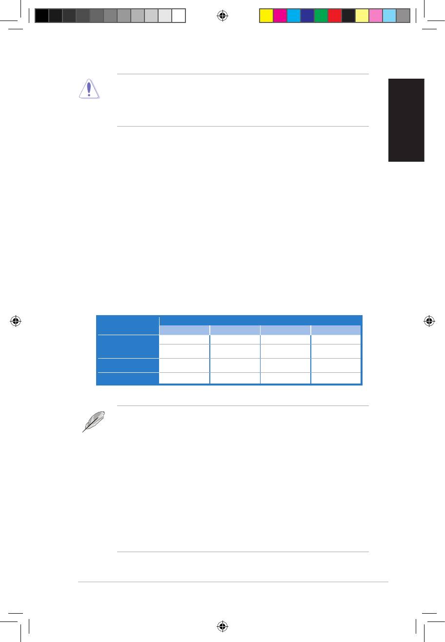
— 4 x 240-pin DIMM sockets support unbuffered non-ECC DDR2 1066/800/667MHz memory modules — Supports up to 16GB system memory * Refer to www.asus.com or this user manual for the Memory QVL (Qualified Vendors Lists) ** When you install a total memory of 4GB or more,…
-
Page 12
System panel connector (Q-Connector) BIOS Features 8Mb Flash ROM, AMI BIOS, PnP, DMI 2.0, WfM 2.0, SM BIOS 2.3, ACPI 2.0a, ASUS EZ Flash 2, ASUS CrashFree BIOS 3 Manageability WfM 2.0, DMI 2.0, WOL by PME, WOR by PME, PXE… -
Page 13: Chapter 1: Product Introduction
This chapter describes the motherboard features and the new technologies it supports. Product introduction…
-
Page 14
Chapter summary Welcome! ………………1-1 Package contents …………….. 1-1 Special features …………….1-2 ASUS P5QL PRO… -
Page 15: Welcome
® The motherboard delivers a host of new features and latest technologies, making it another standout in the long line of ASUS quality motherboards! Before you start installing the motherboard, and hardware devices on it, check the items in your package with the list below.
-
Page 16: Special Features
Green ASUS This motherboard and its packaging comply with the European Union’s Restriction on the use of Hazardous Substances (RoHS). This is in line with the ASUS vision of creating environment-friendly and recyclable products/packaging to safeguard consumers’ health while minimizing the impact on the environment.
-
Page 17: Asus Unique Features
ASUS EPU-4 Engine The new ASUS EPU — the world’s first power saving engine, has been upgraded to a new four-engine version, which provides total system power savings by detecting current PC loadings and intelligently moderating power in real-time.
-
Page 18: Asus Quiet Thermal Solution
ASUS EZ DIY ASUS EZ DIY feature collection provides you with easy ways to install computer components, update the BIOS or back up your favorite settings. ASUS Q-Connector ASUS Q-Connector allows you to easily connect or disconnect the chassis front panel cables to the motherboard.
-
Page 19
See page 4-38 for details. ASUS CrashFree BIOS 3 The ASUS CrashFree BIOS 3 allows users to restore corrupted BIOS data from a bootable floppy disk, a USB flash disk or the motherboard support DVD containing the BIOS file. See page 4-8 for details. -
Page 20: Asus Stylish Features
1.3.4 ASUS Intelligent Overclocking features AI Booster The ASUS AI Booster allows you to overclock the CPU speed in Windows environment without the hassle of booting the BIOS. See page 5-24 for details. Precision Tweaker This feature allows you to fine tune the CPU/memory voltage and gradually increase the memory Front Side Bus (FSB) and PCI Express frequency at 1MHz increment to achieve maximum system performance.
-
Page 21: Chapter 2: Hardware Information
This chapter lists the hardware setup procedures that you have to perform when installing system components. It includes description of the jumpers and connectors on the motherboard. Hardware information…
-
Page 22
Chapter summary Before you proceed …………..2-1 Motherboard overview …………..2-2 Central Processing Unit (CPU) ……….. 2-6 System memory …………….. 2-12 Expansion slots …………….2-18 Jumpers ………………2-21 Connectors …………….. 2-23 ASUS P5QL PRO… -
Page 23: Before You Proceed
ON, in sleep mode, or in soft-off mode. This is a reminder that you should shut down the system and unplug the power cable before removing or plugging in any motherboard component. The illustration below shows the location of the onboard LED. SB_PWR Standby Powered Power P5QL PRO Onboard LED ASUS P5QL PRO…
-
Page 24: Motherboard Overview
Motherboard overview Before you install the motherboard, study the configuration of your chassis to ensure that the motherboard fits into it. Ensure that you unplug the power cord before installing or removing the motherboard. Failure to do so can cause you physical injury and damage motherboard components.
-
Page 25: Motherboard Layout
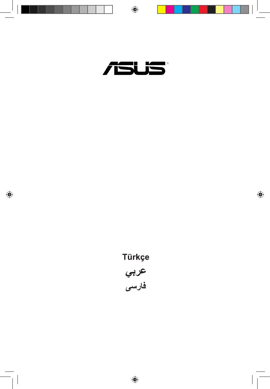
CR2032 3V Lithium Cell BIOS CMOS Power PCI3 1200 Marvell 88SE6102 PCIEX1_2 SB_PWR USBPW1112 SPDIF_OUT CLRTC USBPW7-10 FLOPPY USB1112 USB78 USB910 CHASSIS AAFP PANEL Refer to 2.7 Connectors for more information about rear panel connectors and internal connectors. ASUS P5QL PRO…
-
Page 26: Layout Contents
2.2.4 Layout contents Slots Page DDR2 DIMM slots 2-12 2-20 PCI slots PCI Express x1 slot 2-20 PCI Express x16 slots 2-20 Jumper Page Clear RTC RAM (3-pin CLRTC) 2-21 Keyboard power (3-pin PS2_USBPW56) 2-22 USB device wake-up (3-pin USBPW1-4, USBPW7-10, 2-22 USBPW1112) Rear panel connectors…
-
Page 27
• System power LED (2-pin PLED) • Hard disk drive activity LED (2-pin IDE_LED) • System warning speaker (4-pin SPEAKER) • ATX power button/soft-off button (2-pin PWRSW) • Reset button (2-pin RESET) ASUS Q-connector (system panel) 2-33 ASUS P5QL PRO… -
Page 28: Central Processing Unit (Cpu)
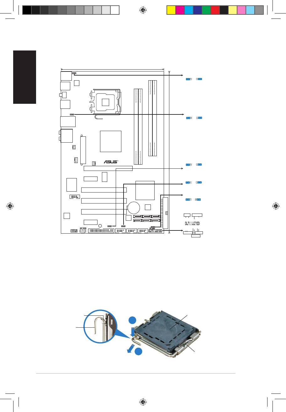
ASUS will shoulder the cost of repair only if the damage is shipment/transit-related. • Keep the cap after installing the motherboard. ASUS will process Return Merchandise Authorization (RMA) requests only if the motherboard comes with the cap on the LGA775 socket.
-
Page 29: Installing The Cpu
PnP cap the arrow to a 135º angle. Load plate Lift the load plate with your thumb and forefinger to a 100º angle (4A), then push the PnP cap from the load plate window to remove (4B). ASUS P5QL PRO…
-
Page 30
Position the CPU over the socket, CPU notch ensuring that the gold triangle is on the bottom-left corner of the socket then fit the socket alignment key into the CPU notch. Gold triangle mark Alignment key Apply several drops of Thermal Interface Material to the exposed area of the CPU that the heatsink will be in contact with, ensuring that it is… -
Page 31
(B) until it snaps into the retention tab. The motherboard supports Intel LGA775 processors with the Intel Enhanced ® ® Intel SpeedStep Technology (EIST) and Hyper-Threading Technology. Refer to ® the Appendix for more information on these CPU features. ASUS P5QL PRO… -
Page 32: Installing The Cpu Heatsink And Fan
2.3.2 Installing the CPU heatsink and fan The Intel® LGA775 processor requires a specially designed heatsink and fan assembly to ensure optimum thermal condition and performance. • When you buy a boxed Intel processor, the package includes the CPU fan ®…
-
Page 33: Uninstalling The Cpu Heatsink And Fan
Rotate each fastener counterclockwise. Pull up two fasteners at a time in a diagonal sequence to disengage the heatsink and fan assembly from the motherboard. Carefully remove the heatsink and fan assembly from the motherboard. ASUS P5QL PRO 2-11…
-
Page 34: System Memory
System memory 2.4.1 Overview The motherboard comes with four Double Data Rate 2 (DDR2) Dual Inline Memory Modules (DIMM) sockets. The figure illustrates the location of the DDR2 DIMM sockets: P5QL PRO 240-pin DDR2 DIMM Sockets Channel Sockets Channel A DIMM_A1 and DIMM_A2 Channel B DIMM_B1 and DIMM_B2…
-
Page 35
DDR2-667. If this happens, contact your memory vendor to check the ODT value. • Due to chipset limitation, DDR2-800 with CL=4 will be downgraded to run at DDR2-667 by default setting. If you want to operate with lower latency, adjust the memory timing manually. ASUS P5QL PRO 2-13… -
Page 36
P5QL PRO Motherboard Qualified Vendors Lists (QVL) DDR2-1066MHz capability DIMM support Size Vendor Part No. Chip Brand Chip No. 512MB Kingston KHX8500D2/512 Kingston Heat-Sink Package 512MB Kingston KVR1066D2N7/512 Elpida E5108AJBG-1J-E Kingston KHX8500D2K2/2GN Kingston Heat-Sink Package Kingston KVR1066D2N7/1G Elpida E5108AJBG-1J-E Kingston KHX8500D2/1G Kingston Heat-Sink Package… -
Page 37
Heat-Sink Package G.SKILL F2-6400CL5D-4GBPQ G.SKILL Heat-Sink Package G.SKILL F2-6400CL4D-4GBPK G.SKILL Heat-Sink Package G.SKILL F2-6400CL5Q-16GNQ G.SKILL Heat-Sink Package OCZ2RPR8002GK Heat-Sink Package OCZ2G800R22GK Heat-Sink Package OCZ2P800R22GK Heat-Sink Package OCZ2VU8004GK Heat-Sink Package OCZ2P8004GK Heat-Sink Package Elixir M2Y1G64TU8HB0B-25C Elixir N2TU51280BE-25C802006Z1DV ASUS P5QL PRO 2-15… -
Page 38
Dual-channel memory configuration. • C*: Supports four modules inserted into both the yellow slots and the black slots as two pairs of Dual-channel memory configuration. Visit the ASUS website for the latest DDR2-1066/800/667MHz QVL. 2-16 Chapter 2: Hardware information… -
Page 39: Installing A Dimm
DIMM. Support the DIMM lightly with your fingers when pressing the retaining clips. The DIMM might get damaged when it flips out with extra force. DDR2 DIMM notch Remove the DIMM from the socket. ASUS P5QL PRO 2-17…
-
Page 40: Expansion Slots
Expansion slots In the future, you may need to install expansion cards. The following sub-sections describe the slots and the expansion cards that they support. Ensure to unplug the power cord before adding or removing expansion cards. Failure to do so may cause you physical injury and damage motherboard components.
-
Page 41: Interrupt Assignments
Onboard IDE PORT shared Onboard HD Audio shared Onboard LAN shared Onchip SATA1 shared shared Onchip SATA2 shared PCI Card1 shared shared shared shared PCI Card2 shared shared shared shared PCI Card3 shared shared shared shared ASUS P5QL PRO 2-19…
-
Page 42: Pci Slots
2.5.4 PCI slots The PCI slots support cards such as a LAN card, SCSI card, USB card, and other cards that comply with PCI specifications. The photo shows a LAN card installed on a PCI slot. 2.5.5 PCI Express x1 slots This motherboard supports PCI Express x1 network cards, SCSI cards and other cards that comply with the PCI Express…
-
Page 43: Jumpers
• Due to the chipset limitation, AC power off is required prior using C.P.R. function. You must turn off and on the power supply or unplug and plug the power cord before reboot the system. ASUS P5QL PRO 2-21…
-
Page 44: Keyboard Power
Keyboard power (3-pin PS2_USBPW56) This jumper allows you to enable or disable the keyboard and USB port 5-6 wake-up feature. When you set this jumper to pins 2-3 (+5VSB), you can wake up the computer by pressing a key on the keyboard (the default is the Space Bar) or using a USB device.
-
Page 45: Connectors
Line In port (light blue). This port connects the tape, CD, DVD player, or other audio sources. Line Out port (lime). This port connects a headphone or a speaker. In 4-channel, 6-channel, and 8-channel configuration, the function of this port becomes Front Speaker Out. ASUS P5QL PRO 2-23…
-
Page 46
Microphone port (pink). This port connects a microphone. Side Speaker Out port (gray). This port connects the side speakers in an 8-channel audio configuration. Refer to the audio configuration table on the next page for the function of the audio ports in 2, 4, 6, or 8-channel configuration. Audio 2, 4, 6, or 8-channel configuration Headset Port… -
Page 47: Internal Connectors
Connect the S/PDIF Out module cable to this connector, then install the module to a slot opening at the back of the system chassis. SPDIF_OUT P5QL PRO Digital Audio Connector The S/PDIF module is purchased separately. ASUS P5QL PRO 2-25…
-
Page 48
IDE connector (40-1 pin PRI_EIDE) The onboard IDE connector is for the Ultra DMA 133/100/66 signal cable. There are three connectors on each Ultra DMA 133/100/66 signal cable: blue, black, and gray. Connect the blue connector to the motherboard’s IDE connector, then select one of the following modes to configure your device. -
Page 49
Connect the right-angle side of SATA signal cable to SATA device. Or you may connect the right-angle side of SATA cable to the onboard SATA port to avoid mechanical conflict with huge graphics cards. ASUS P5QL PRO 2-27… -
Page 50
Never connect a 1394 cable to the USB connectors. Doing so will damage the motherboard! You can connect the front panel USB cable to the ASUS Q-Connector (USB, blue) first, and then install the Q-Connector (USB) to the USB connector onboard if your chassis supports front panel USB ports. -
Page 51
CPU FAN IN CPU FAN PWM P5QL PRO Fan Connectors Only the CPU_FAN connector supports the ASUS Q-FAN feature. Serial port connector (10-1 pin COM1) This connector is for a serial (COM) port. Connect the serial port module cable to this connector, then install the module to a slot opening at the back of the system chassis. -
Page 52: Chassis Intrusion Connector
Chassis intrusion connector (4-1 pin CHASSIS) This connector is for a chassis-mounted intrusion detection sensor or switch. Connect one end of the chassis intrusion sensor or switch cable to this connector. The chassis intrusion sensor or switch sends a high-level signal to this connector when a chassis component is removed or replaced.
-
Page 53
CPU: Intel ® Pentium ® Extreme 3.73GHz Memory: 512 MB DDR2 (x4) Graphics card: ASUS EAX1900XT Parallel ATA device: IDE hard disk drive Serial ATA device: SATA hard disk drive (x2) Optical drive: DVD-RW ASUS P5QL PRO 2-31… -
Page 54: System Panel Connector
12. System panel connector (20-8 pin PANEL) This connector supports several chassis-mounted functions. PANEL PLED SPEAKER RESET +IDE_LED PWRSW Requires an ATX power supply System Panel Connector P5QL PRO • System power LED (2-pin PLED) This 2-pin connector is for the system power LED. Connect the chassis power LED cable to this connector.
-
Page 55
Q-Connector (system panel) You can use ASUS Q-Connector to connect / disconnect chassis front panel cables by only a few steps. Directions below shows how to install ASUS Q-Connector. Step1. Connect correct front panel to ASUS Q-Connector first. You can refer to the marking on Q-Connector itself to know the detail pin definition. -
Page 56
2-34 Chapter 2: Hardware information… -
Page 57: Chapter 3: Powering Up
This chapter describes the power up sequence, the vocal POST messages, and ways of shutting down the system. Powering up…
-
Page 58
Chapter summary Starting up for the first time …………3-1 Turning off the computer …………. 3-2 ASUS P5QL PRO… -
Page 59: Starting Up For The First Time
One continuous beep followed by three No VGA detected short beeps One continuous beep followed by four Hardware component failure short beeps At power on, hold down the <Delete> key to enter the BIOS Setup. Follow the instructions in Chapter 4. ASUS P5QL PRO…
-
Page 60: Turning Off The Computer
Turning off the computer 3.2.1 Using the OS shut down function If you are using Windows® XP: Click the Start button then select Turn Off Computer. Click the Turn Off button to shut down the computer. The power supply should turn off after Windows® shuts down. If you are using Windows®…
-
Page 61: Chapter 4: Bios Setup
This chapter tells how to change the system settings through the BIOS Setup menus. Detailed descriptions of the BIOS parameters are also provided. BIOS setup…
-
Page 62
Managing and updating your BIOS ……….4-1 BIOS setup program …………..4-10 Main menu ……………… 4-13 Ai Tweaker menu ……………. 4-17 Advanced menu …………….. 4-22 Power menu …………….4-28 Boot menu ……………… 4-31 Tools menu …………….. 4-36 Exit menu ………………4-40 ASUS P5QL PRO… -
Page 63: Managing And Updating Your Bios
ASUS Update: Updates the BIOS in Windows environment. ® ASUS EZ Flash 2: Updates the BIOS in DOS mode using a floppy disk or a USB flash disk. ASUS AFUDOS: Updates the BIOS in DOS mode using a bootable floppy disk.
-
Page 64
To update the BIOS through the Internet: Launch the ASUS Update utility from the Windows desktop by clicking Start ® > Programs > ASUS > ASUSUpdate > ASUSUpdate. The ASUS Update main window appears. Select Update BIOS from Select the ASUS FTP site nearest… -
Page 65
To update the BIOS through a BIOS file: desktop by clicking Start Launch the ASUS Update utility from the Windows ® > Programs > ASUS > ASUSUpdate > ASUSUpdate. The ASUS Update main window appears. Select Update BIOS from a file option from the drop-down menu, then click Next. -
Page 66: Creating A Bootable Floppy Disk
4.1.2 Creating a bootable floppy disk Do any one of the following to create a bootable floppy disk. DOS environment a. Insert a 1.44MB floppy disk into the drive. b. At the DOS prompt, type format A:/S then press <Enter>. Windows XP environment ®…
-
Page 67: Asus Ez Flash 2 Utility
4.1.3 ASUS EZ Flash 2 utility The ASUS EZ Flash 2 feature allows you to update the BIOS without having to go through the long process of booting from a floppy disk and using a DOS-based utility. The EZ Flash 2 utility is built-in the BIOS chip so it is accessible by pressing <Alt>…
-
Page 68: Afudos Utility
Updating the BIOS file To update the BIOS file using the AFUDOS utility: Visit the ASUS website (www.asus.com) and download the latest BIOS file for the motherboard. Save the BIOS file to a bootable floppy disk. Chapter 4: BIOS setup…
-
Page 69
A:\>afudos /iP5QLPRO.ROM The utility verifies the file and starts updating the BIOS. A:\>afudos /iP5QLPRO.ROM AMI Firmware Update Utility — Version 1.19(ASUS V2.07(03.11.24BB)) Copyright (C) 2002 American Megatrends, Inc. All rights reserved. WARNING!! Do not turn off power during flash BIOS Reading file ..done Reading flash .. -
Page 70: Asus Crashfree Bios 3 Utility
4.1.5 ASUS CrashFree BIOS 3 utility The ASUS CrashFree BIOS 3 is an auto recovery tool that allows you to restore the BIOS file when it fails or gets corrupted during the updating process. You can update a corrupted BIOS file using the motherboard support DVD, a floppy disk or a USB flash disk that contains the updated BIOS file.
-
Page 71: Recovering The Bios From The Support Dvd
Restart the system after the utility completes the updating process. • Only the USB flash disk with FAT 32/16 format and single partition can support ASUS CrashFree BIOS 3. The device size should be smaller than 8GB. • DO NOT shut down or reset the system while updating the BIOS! Doing so…
-
Page 72: Bios Setup Program
The BIOS setup screens shown in this section are for reference purposes only, and may not exactly match what you see on your screen. • Visit the ASUS website (www.asus.com) to download the latest BIOS file for this motherboard. 4-10…
-
Page 73: Bios Menu Screen
At the bottom right corner of a menu screen are the navigation keys for that particular menu. Use the navigation keys to select items in the menu and change the settings. Some of the navigation keys differ from one screen to another. ASUS P5QL PRO 4-11…
-
Page 74: Menu Items
4.2.4 Menu items The highlighted item on the BIOS SETUP UTILITY Main Ai Tweaker Advanced Power Boot Tools Exit menu bar displays the specific Use [ENTER], [TAB] or System Time [14:14:35] [SHIFT-TAB] to select items for that menu. For System Date [Wed 04/16/2008] a field.
-
Page 75: Main Menu
Allows you to set the system time. 4.3.2 System Date [Day xx/xx/xxxx] Allows you to set the system date. 4.3.3 Legacy Diskette A [1.44M, 3.5 in.] Sets the type of floppy drive installed. Configuration options: [Disabled] [720K, 3.5 in.] [1.44M, 3.5 in.] ASUS P5QL PRO 4-13…
-
Page 76: Sata 1~6
4.3.4 SATA 1~6 While entering Setup, the BIOS automatically detects the presence of IDE devices. There is a separate sub-menu for each IDE device. Select a device item then press <Enter> to display the IDE device information. BIOS SETUP UTILITY Main SATA 1 Select the type of…
-
Page 77: Storage Configuration
Disables or enables device write protection. This will be effective only if device is accessed throuh BIOS. Configuration option: [Disabled] [Enabled] IDE Detect Time Out (Sec) [35] Selects the time out value for detecting ATA/ATAPI devices. Configuration options: [0] [5] [10] [15] [20] [25] [30] [35] ASUS P5QL PRO 4-15…
-
Page 78: System Information
4.3.6 System Information This menu gives you an overview of the general system specifications. The BIOS automatically detects the items in this menu. BIOS SETUP UTILITY Main Bios Information Version : 0314 Build Date : 05/27/08 Processor Type : Intel(R) Core(TM)2 CPU 6300 @ 1.86GHz Speed : 1866MHz Count…
-
Page 79: Ai Tweaker Menu
Select either one of the preset overclocking configuration options: Manual — allows you to individually set overclocking parameters. Auto — loads the optimal settings for the system. The follow items appear only when you set the [Ai Overclock Tuner] item to [Manual]. ASUS P5QL PRO 4-17…
-
Page 80
FSB Frequency [xxx] Displays the frequency sent by the clock generator to the system bus and PCI bus. Use the <+> and <-> keys to adjust the FSB frequency. You can also type the desired FSB frequency using the numeric keypad. The values range from 200 to 800. -
Page 81
Configuration options: [Auto] [1 DRAM Clocks] ~ [15 DRAM Clocks] WRITE to WRITE Delay (D) [Auto] Configuration options: [Auto] [1 DRAM Clocks] ~ [15 DRAM Clocks] 3rd Information: 13-5-1-5-5 WRITE to PRE Delay [Auto] Configuration options: [Auto] [1 DRAM Clocks] ~ [15 DRAM Clocks] ASUS P5QL PRO 4-19… -
Page 82
READ to PRE Delay [Auto] Configuration options: [Auto] [1 DRAM Clocks] ~ [15 DRAM Clocks] PRE to PRE Delay [Auto] Configuration options: [Auto] [1 DRAM Clocks] ~ [3 DRAM Clocks] ALL PRE to ACT Delay [Auto] Configuration options: [Auto] [1 DRAM Clocks] ~ [15 DRAM Clocks] ALL PRE to REF Delay [Auto] Configuration options: [Auto] [1 DRAM Clocks] ~ [15 DRAM Clocks] DRAM Static Read Control [Auto]… -
Page 83
Allows you to select the CPU Load-Line mode. Set to [Disabled] to follow Intel specifications, or to [Enabled] to improve CPU VDroop directly. Configuration options: [Auto] [Disabled] [Enabled] CPU GTL Reference [Auto] Allows you to set the CPU GTL voltage reference. Configuration options: [Auto] [0.667x] [0.65x] [0.63x] [0.615x] ASUS P5QL PRO 4-21… -
Page 84: Advanced Menu
CPU Spread Spectrum [Auto] Allows you to set the CPU spread spectrum. Configuration options: [Auto] [Disabled] PCIE Spread Spectrum [Auto] Allows you to set the PCIE spread spectrum. Configuration options: [Auto] [Disabled] Advanced menu The Advanced menu items allow you to change the settings for the CPU and other system devices.
-
Page 85: Cpu Configuration
Enables or disables Intel® Virtualization Technology. Virtualization enhanced by Intel® Virtualization Technology allows a platform to run multiple operating systems and applications in independent partitons. With virtualization, one computer system can function as multiple virtual systems. Configuration options: [Enabled] [Disabled] ASUS P5QL PRO 4-23…
-
Page 86: Chipset
CPU TM function [Enabled] Enables or disables Intel® CPU Thermal Monitor (TM) function, a CPU overheating protection function. When enabled, the CPU core frequency and voltage are reduced when the CPU overheats. Configuration options: [Disabled] [Enabled] Execute-Disable Bit Capability [Enabled] Allows you to enable or disable the No-Execution Page Protection Technology.
-
Page 87: Onboard Devices Configuration
SPDIF_OUT Mode Setting [SPDIF Output] Allows you to set the SPDIF_OUT mode. Configuration options: [HDMI Output] [SPDIF Output] Marvell IDE controller [Enabled] Allows you to disable or enable the onboard Marvell® IDE controller. Configuration options: [Enabled] [Disabled] ASUS P5QL PRO 4-25…
-
Page 88: Usb Configuration
Onboard PCIE GbE LAN [Enabled] Configuration options: [Enabled] [Disabled] LAN Option ROM [Disabled] This item appears only when you enable the previous item. Configuration options: [Disabled] [Enabled] Serial Port1 Address [3F8/IRQ4] Allows you to select the Serial Port1 base address. Configuration options: [Disabled] [3F8/IRQ4] [2F8/IRQ3] [3E8/IRQ4] [2E8/IRQ3] 4.5.4 USB Configuration…
-
Page 89: Pci Pnp
When set to [No], BIOS configures all the devices in the system. When set to [Yes] and if you install a Plug and Play operating system, the operating system configures the Plug and Play devices not required for boot. Configuration options: [No] [Yes] ASUS P5QL PRO 4-27…
-
Page 90: Power Menu
Power menu The Power menu items allow you to change the settings for the Advanced Power Management (APM). Select an item then press <Enter> to display the configuration options. BIOS SETUP UTILITY Main Ai Tweaker Advanced Power Boot Tools Exit Select the ACPI state Suspend Mode [Auto]…
-
Page 91: Apm Configuration
Allows you to enable or disable the PME to wake up from S5 by PCI devices. Configuration options: [Disabled] [Enabled] Power On By PCIE Devices [Disabled] Allows you to enable or disable the PCIE devices to generate a wake event. Configuration options: [Disabled] [Enabled] ASUS P5QL PRO 4-29…
-
Page 92: Hardware Monitor
Power On By PS/2 Keyboard [Disabled] Allows you to disable the Power On by PS/2 keyboard function or set specific keys on the PS/2 keyboard to turn on the system. This feature requires an ATX power supply that provides at least 1A on the +5VSB lead. Configuration options: [Disabled] [Space Bar] [Ctrl-Esc] [Power Key] Power On By PS/2 Mouse [Disabled] When set to [Enabled], this parameter allows you to use the PS/2 mouse to turn on…
-
Page 93: Boot Menu
(Floppy Drive B:) Security may appear when you set the CD-ROM drive as the first boot device. Select Screen Select Item Enter Go to Sub Screen General Help Save and Exit Exit v02.61 (C)Copyright 1985-2008, American Megatrends, Inc. ASUS P5QL PRO 4-31…
-
Page 94: Boot Device Priority
4.7.1 Boot Device Priority BIOS SETUP UTILITY Boot Boot Device Priority Specifies the boot sequence from the availabe devices. 1st Boot Device [1st FLOPPY DRIVE] 2nd Boot Device [Hard Drive] A device enclosed 3rd Boot Device [ATAPI CD-ROM] in parenthesis has been disabled in the corresponding type menu.
-
Page 95: Boot Settings Configuration
Configuration options: [Disabled] [Enabled] Full Screen Logo [Enabled] This allows you to enable or disable the full screen logo display feature. Configuration options: [Disabled] [Enabled] Set this item to [Enabled] to use the ASUS MyLogo2 feature. ™ AddOn ROM Display Mode [Force BIOS] Sets the display mode for option ROM.
-
Page 96: Security
Hit ‘DEL’ Message Display [Enabled] When set to Enabled, the system displays the message Press DEL to run Setup during POST. Configuration options: [Disabled] [Enabled] Interrupt 19 Capture [Disabled] When set to [Enabled], this function allows the option ROMs to trap Interrupt 19. Configuration options: [Disabled] [Enabled] 4.7.3 Security…
-
Page 97: Change User Password
To set a User Password: Select the Change User Password item and press <Enter>. From the password box, type a password composed of at least six letters and/or numbers, then press <Enter>. Confirm the password when prompted. ASUS P5QL PRO 4-35…
-
Page 98: Tools Menu
Ai Tweaker Advanced Power Boot Tools Exit Press ENTER to run v02.61 (C)Copyright 1985-2008, American Megatrends, Inc. ASUS EZ Flash 2 the utility to select and update BIOS. Express Gate [Enabled] This utility doesn’t Enter OS Timer [10 Seconds] support :…
-
Page 99: Asus Ez Flash 2
4.8.1 ASUS EZ Flash 2 Allows you to run ASUS EZ Flash 2. When you press <Enter>, a confirmation message appears. Use the left/right arrow key to select between [Yes] or [No], then press <Enter> to confirm your choice. Please see section 4.1.3 for details.
-
Page 100: Ai Net 2
Check Atheros LAN cable [Disabled] Enables or disables checking of the Atheros LAN cable during the Power-On Self-Test (POST). Configuration options: [Disabled] [Enabled] 4.8.4 ASUS O.C. Profile BIOS SETUP UTILITY Tools O.C. PROFILE Configuration Save BIOS settings to Profile 1 O.C.
-
Page 101
This function can support devices such as USB flash disk or floppy disk with FAT 32/16 format and single partition only. • DO NOT shut down or reset the system while updating the BIOS to prevent the system boot failure! ASUS P5QL PRO 4-39… -
Page 102: Exit Menu
Exit menu The Exit menu items allow you to load the optimal or failsafe default values for the BIOS items, and save or discard your changes to the BIOS items. BIOS SETUP UTILITY Main Ai Tweaker Advanced Power Boot Tools Exit Exit Options Exit system setup…
-
Page 103: Chapter 5: Software Support
This chapter describes the contents of the support CD that comes with the motherboard package. Software support…
-
Page 104
Chapter summary Installing an operating system ……….. 5-1 Support DVD information …………5-1 Software information …………..5-10 ASUS P5QL PRO… -
Page 105: Installing An Operating System
The contents of the support DVD are subject to change at any time without notice. Visit the ASUS website at www.asus.com for updates. 5.2.1 Running the support DVD Place the support DVD to the optical drive.
-
Page 106: Drivers Menu
The Drivers menu shows the available device drivers if the system detects installed devices. Install the necessary drivers to activate the devices. ASUS InstAll — Installation Wizard for Drivers Installs the ASUS InstAll — Installation wizard for drivers. Intel Chipset Inf Update Program Installs the Intel chipset Inf update program.
-
Page 107: Utilities Menu
Installs all of the utilities through the Installation Wizard. ASUS Update The ASUS Update utility allows you to update the motherboard BIOS in a Windows® environment. This utility requires an Internet connection either through a network or an Internet Service Provider (ISP).
-
Page 108
Installs the Corel MediaOne Starter application to easily manage, edit share and protect your multimedia data. CyberLink PowerBackup Installs CyberLink PowerBackup to back up and restore your data easily. ASUS Express Gate Installer Allows you to install or update Express Gate functions. Atheros Ethernet Utility Installs the Atheros Ethernet utility. -
Page 109: Manual Menu
Adobe® Acrobat® Reader from the Utilities menu before opening a user manual file. Realtek HD Audio User’s Manual Allows you to open the Realtek HD Audio User Manual. ASUS Motherboard Installation Guide Allows you to open the ASUS Motherboard Installation Guide. ASUS P5QL PRO…
-
Page 110: Asus Contact Information
5.2.5 ASUS Contact information Click the Contact tab to display the ASUS contact information. You can also find this information on the inside front cover of this user guide. Chapter 5: Software support…
-
Page 111: Other Information
The icons on the top right corner of the screen give additional information on the motherboard and the contents of the support DVD. Click an icon to display the specified information. Motherboard Info Displays the general specifications of the motherboard. Browse this DVD Displays the support DVD contents in graphical format. ASUS P5QL PRO…
-
Page 112: Technical Support Form
Technical support Form Displays the ASUS Technical Support Request Form that you have to fill out when requesting technical support. Filelist Displays the contents of the support DVD and a brief description of each in text format. Chapter 5: Software support…
-
Page 113: Software Information
5.3.1 ASUS MyLogo2™ The ASUS MyLogo2™ utility lets you customize the boot logo. The boot logo is the image that appears on screen during the Power-On Self-Tests (POST). The ASUS MyLogo2™ is automatically installed when you install the ASUS Update utility from the Support DVD.
-
Page 114
Ratio box. When the screen returns to the ASUS Update utility, flash the original BIOS to load the new boot logo. 10. After flashing the BIOS, restart the computer to display the new boot logo during POST. -
Page 115: Audio Configurations
Audio Manager icon on the taskbar. From the taskbar, double-click on the SoundEffect icon to display the Realtek HD Audio Manager. Realtek HD Audio Manager Realtek HD Audio Manager Exit button Configuration options Minimize button Control settings window Information button ASUS P5QL PRO 5-11…
-
Page 116: Configuration Options
Information Click the information button ( ) to display information about the audio driver version, DirectX version, audio controller, audio codec, and language setting. Minimize Click the minimize button ( ) to minimize the window. Exit Click the exit button ( ) to exit the Realtek HD Audio Manager.
-
Page 117
Manager, click the Audio I/O tab. Click the drop-down menu to select the channel configuration. The control settings window displays the status of connected devices. Click for analog and digital options. Click <OK> to effect the Audio I/O settings and exit ASUS P5QL PRO 5-13… -
Page 118
Microphone The Microphone option allows you configure your input/output settings and to check if your audio devices are connected properly. To set the Microphone options: From the Realtek HD Audio Manager, click the Microphone tab. Click the Noise Suppression option button to reduce the static background noise when recording. -
Page 119: Asus Pc Probe Ii
To launch the PC Probe II from the Windows desktop, click Start > All Programs ® > ASUS > PC Probe II > PC Probe II v1.xx.xx. The PC Probe II main window appears. After launching the application, the PC Probe II icon appears in the Windows ®…
-
Page 120
Button Function Opens the Configuration window Opens the Report window Opens the Desktop Management Interface window Opens the Peripheral Component Interconnect window Opens the Windows Management Instrumentation window Opens the hard disk drive, memory, CPU usage window Shows/Hides the Preference section Minimizes the application Closes the application Sensor alert… -
Page 121
Click to clicking the or buttons. You can increase also adjust the threshold values value using the Config window. Click to You cannot adjust the sensor decrease threshold values in a small value monitoring panel. ASUS P5QL PRO 5-17… -
Page 122
Monitoring sensor alert The monitor panel turns red when a component value exceeds or is lower than the threshold value. Refer to the illustrations below. Small display Large display WMI browser Click to display the WMI (Windows Management Instrumentation) browser. This browser displays various Windows®… -
Page 123
Click a hard disk drive to display the information on the right panel. The pie chart at the bottom of the window represents the used (blue) and the available HDD space. ASUS P5QL PRO 5-19… -
Page 124
Memory usage The Memory tab shows both used and available physical memory. The pie chart at the bottom of the window represents the used (blue) and the available Configuring PC Probe II Click to view and adjust the sensor threshold values. The Config window has two tabs: Sensor/Threshold and Preference. -
Page 125: Asus Ai Suite
5.3.4 ASUS AI Suite ASUS AI Suite allows you to launch AI Booster, AI Nap, and Fan Xpert utilities easily. Installing AI Suite To install AI Suite on your computer: Place the support DVD to the optical drive. The Drivers installation tab appears if your computer has an enabled Autorun feature.
-
Page 126
Other feature buttons Click on right corner of the main window to open the monitor window. Displays the CPU/ system temperature, CPU/memory/PCIE voltage, and CPU/ chassis fan speed Displays the FSB/CPU frequency Click on right corner of the expanded window to switch the temperature from degrees Centigrade to degrees Fahrenheit. -
Page 127: Asus Ai Booster
5.3.5 ASUS AI Booster The ASUS AI Booster application allows you to overclock the CPU speed in WIndows environment without the hassle of booting the BIOS. ® After installing AI Suite from the bundled support DVD, you can launch the utility…
-
Page 128: Asus Ai Nap
5.3.6 ASUS AI Nap This feature allows you to minimize the power consumption of your computer whenever you are away. Enable this feature for minimum power consumption and a more quiet system operation. After installing AI Suite from the bundled support DVD, you can launch the utility by double-clicking the AI Suite icon on the Windows OS taskbar and click the AI Nap button on the AI Suite main window.
-
Page 129: Asus Fan Xpert
Install AI Suite from the bundled support DVD. To launch the ASUS Fan Xpert utility, double-click the AI Suite icon on the Windows notification bar and click ®…
-
Page 130: Asus Epu-4 Engine
5.3.8 ASUS EPU-4 Engine ASUS EPU-4 Engine is an energy-efficient tool that satisfies different computing needs. This utility provides three modes that you can select to enhance system performance or save power. Selecting Auto mode will have the system shift modes automatically according to current system status.
-
Page 131: Engine Main Menu
Settings for each mode (refer to the next page for further information) *• Click Current to show the CO2 that has been reduced since you click the Renew button *• Click Total to show the total CO2 that has been reduced since you launched 4 Engine. ASUS P5QL PRO 5-27…
-
Page 132
Setting menu Click Setting ( ) from the 4 Engine main menu to display configuration options in each mode. Some options in certain modes are dimmed, meaning that they are not available. Click to select a mode Click the arrow to see more options Restore default… -
Page 133
Light/Medium/ Light/Medium/ Heavy Heavy Fan Control Keep Bios Keep Bios Setting/Slow Setting/Quiet AI Nap Never/After 3 Never/After 3 Never/After 3 Never/After 3 Idle Time mins–After 5 mins–After 5 mins–After 5 mins–After 5 hours hours hours hours ASUS P5QL PRO 5-29… -
Page 134: Asus Express Gate
5.3.9 ASUS Express Gate ASUS Express Gate is an instant-on environment that gives you quick access to the Internet. Within a few seconds of powering on your computer, you will be at the Express Gate menu where you can start the web browser, Skype, or other Express Gate softwares.
-
Page 135
The very first time you enter the Express Gate environment (by launching either web or Skype from the first screen), a first time wizard will guide you through basic Express Gate configurations. Basic configurations include language, date and time and screen resolution. ASUS P5QL PRO 5-31… -
Page 136
Once inside the Express Gate environment, click on the icons on the LaunchBar, by default at bottom of the screen, to launch or switch between softwares. You can re-arrange, re-size and move windows. Bring a window to the foreground by clicking within it or by clicking on its corresponding software icon. Re-size a window by dragging any of its four corners. -
Page 137: Using The Configuration Panel
Express Gate to finish clearing the settings. This is also useful in the rare case where settings might become corrupted. The first-time Wizard will run again when you enter the Express Gate environment after clearing its settings. ASUS P5QL PRO 5-33…
-
Page 138: Using The Launchbar
USB drive. If a USB device is detected, the icon contains a green arrow. ASUS Express Gate supports file uploading from SATA HDDs, ODDs and USB drive and downloading to USB drives only. Shows network status; click to configure network.
-
Page 139
Click to choose input language and method as well as keyboard shortcuts (Ctrl-Space by default). Click to change LaunchBar options (auto-hide, docking position, etc). Click to show the ASUS Utility panel. Click to show About Express Gate. Click to open Express Gate Help. -
Page 140
Open Network. Network Make the proper network configurations. Each network interface is enabled immediately when you check the box next to it. • If you use a network cable connected to a home router (which is then connected to your DSL/cable modem), enable both LAN1 and LAN2. Express Gate will automatically use whichever port (LAN1 or LAN2) is connected. -
Page 141
Shows user- created image album(s) Image control bar ASUS Express Gate supports HDDs connected to motherboard chipset- controlled onboard SATA ports only. All onboard extended SATA ports and external SATA ports are NOT supported. ASUS P5QL PRO 5-37… -
Page 142: Updating Express Gate
Express Gate software will be released regularly, adding refinements or new applications. You can find original version of the software on the support DVD or download new versions from the ASUS support website. To update Express Gate Double-click the Express Gate setup file to start software update.
-
Page 143: Appendix: Cpu Features
The Appendix describes the CPU features and technologies that the motherboard supports. CPU features…
-
Page 144
Chapter summary ® Intel EM64T ………………A-1 ® Enhanced Intel SpeedStep Technology (EIST) ……A-1 ® Intel Hyper-Threading Technology ………..A-3 ASUS P5QL PRO… -
Page 145: Intel ® Em64T
32-bit operating systems. • The motherboard comes with a BIOS file that supports EM64T. You can download the latest BIOS file from the ASUS website (www.asus.com/ support/download/) if you need to update the BIOS file. See Chapter 4 for details.
-
Page 146: Using The Eist
A.2.2 Using the EIST To use the EIST feature: Turn on the computer, then enter the BIOS Setup. Go to the Advanced Menu, highlight CPU Configuration, then press <Enter>. Set the Intel(R) SpeedStep Technology item to [Enabled], then press <Enter>. See page 4-24 for details. Press <F10>…
-
Page 147: Intel ® Hyper-Threading Technology
Power up the system and enter the BIOS Setup. Go to Advanced > CPU Configuration, ensure that the Hyper-Threading Technology item is set to [Enabled]. The BIOS item appears only if you installed a CPU that supports Hyper-Threading Technology. Restart the computer. ASUS P5QL PRO…
-
Page 148
Appendix: CPU features…
-
Драйверы
45
-
Инструкции по эксплуатации
11
Языки:

ASUS P5QL PRO инструкция по эксплуатации
(148 страниц)
- Языки:Английский
-
Тип:
PDF -
Размер:
3.65 MB -
Описание:
P5QL PRO user’s manual(English)
Просмотр

ASUS P5QL PRO инструкция по эксплуатации
(148 страниц)
- Языки:Английский
-
Тип:
PDF -
Размер:
3.54 MB -
Описание:
P5QL PRO user’s manual(English)
Просмотр

ASUS P5QL PRO инструкция по эксплуатации
(40 страниц)
- Языки:Молдавский, Немецкий
-
Тип:
PDF -
Размер:
1.65 MB -
Описание:
Motherboard Installation Guide (German)
Motherboard Installation Guide (German)
Просмотр

ASUS P5QL PRO инструкция по эксплуатации
(148 страниц)
- Языки:Китайский
-
Тип:
PDF -
Размер:
11.43 MB -
Описание:
P5QL PRO user’s manual (Traditional Chinese)
Просмотр

ASUS P5QL PRO инструкция по эксплуатации
(44 страницы)
- Языки:Китайский, Молдавский
-
Тип:
PDF -
Размер:
1.88 MB -
Описание:
Motherboard Installation Guide (Simplified Chinese)
Просмотр

ASUS P5QL PRO инструкция по эксплуатации
(44 страницы)
- Языки:Китайский, Молдавский
-
Тип:
PDF -
Размер:
2.02 MB -
Описание:
Motherboard Installation Guide (Traditional Chinese)
Просмотр

ASUS P5QL PRO инструкция по эксплуатации
(8 страниц)
- Языки:Китайский, Молдавский
-
Тип:
PDF -
Размер:
2.67 MB -
Описание:
Motherboard DIY Troubleshooting Guide (Traditional Chinese version)
Просмотр

ASUS P5QL PRO инструкция по эксплуатации
(40 страниц)
- Языки:Молдавский, Японский
-
Тип:
PDF -
Размер:
1.73 MB -
Описание:
Motherboard Installation Guide (Japanese)
Просмотр

ASUS P5QL PRO инструкция по эксплуатации
(40 страниц)
- Языки:Молдавский, Французский
-
Тип:
PDF -
Размер:
1.64 MB -
Описание:
Motherboard Installation Guide (French)
Просмотр

ASUS P5QL PRO инструкция по эксплуатации
(721 страница)
- Языки:Молдавский
-
Тип:
PDF -
Размер:
43.88 MB -
Описание:
Motherboard Installation Guide (Multiple Languages)
Просмотр

ASUS P5QL PRO инструкция по эксплуатации
(38 страниц)
-
Тип:
PDF -
Размер:
1.81 MB -
Описание:
P5QL PRO Quick Start Guide for Multiple Languages
Просмотр
На NoDevice можно скачать инструкцию по эксплуатации для ASUS P5QL PRO. Руководство пользователя необходимо для ознакомления с правилами установки и эксплуатации ASUS P5QL PRO. Инструкции по использованию помогут правильно настроить ASUS P5QL PRO, исправить ошибки и выявить неполадки.
A3782
P5QL PRO
Quick Start Guide
Français
日本語
한국어
ไทย
Bahasa Indonesia
Tiếng Việt
First Edition Published June 2008
Copyright © 2008 ASUSTeK COMPUTER INC. All Rights Reserved.
15G0620851B0
A3782_P5QL PRO.indb 1 6/2/08 1:39:01 PM
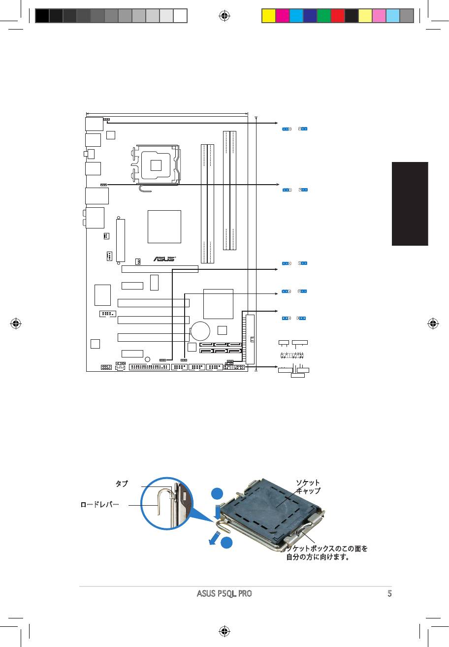
1. Schéma de la Carte Mère
19.3cm (7.6in)
PS/2KBMS
PS2_USBPW56
T:Mouse
PS2_USBPW56
1
2
2
3
B:Keyboard
+5VSB
+5VSB
(D
e
fault)
USB56
ATX12V
LGA775
SPDIF_O1
USB34
USBPW1-4
1
2
2
3
+5VSB
+5VSB
LAN1_USB12
(D
e
fault)
AUDIO
Intel
DDR2 DIMMB1 (64 bit,240-pin module)
DDR2 DIMMB2 (64 bit,240-pin module)
P43
DDR2 DIMMA1 (64 bit,240-pin module)
DDR2 DIMMA2 (64 bit,240-pin module)
CHA_FAN
P5QL PRO
EATXPWR
30.5cm (12in)
USBPW1112
CPU_FAN
1
2
2
3
PWR_FAN
+5
V
+5VSB
PCIEX16
(D
e
fa
u
lt
)
ICS
PCIEX1_1
USBPW7-10
9LPRS916JGLF
1
2
2
3
+5
V
+5VSB
(Defau
lt
)
Super I/O
Intel
PCI1
ICH10
CLRTC
1 2 2 3
COM1
PCI2
Normal
Clear RTC
(Default)
CR2032 3V
4Mb
Lithium Cell
BIOS
CMOS Power
PCI3
PANEL
ALC
PLED SPEAKER
1200
88SE6102
Marvell
PLED+
PLED-
Ground
Ground
Speaker
+5V
PCIEX1_2
SB_PWR
SPDIF_OUT
USBPW1112
USBPW7-10
CLRTC
IDE_LED+
IDE_LED-
PWR
Ground
Reset
Ground
CD
AAFP
FLOPPY
USB1112 USB78 USB910
CHASSIS
PANEL
+IDE_LED
RESET
PWRSW
*
Requires an ATX power supply
2. Installation du Processeur
®
Suivez cette procédure pour installer un processeur Intel
dans le paquet
775-land.
1. Appuyez sur le levier de chargement avec votre pouce (A), puis
déplacez-le vers le gauche (B) jusqu’à ce qu’il soit détaché de la
languette de retenue.
Languette de
Capuchon PnP
retenue
A
Levier de
chargement
B
Ce côté du boîtier cam doit
être face à vous.
A3782_P5QL PRO.indb 2 6/2/08 1:39:07 PM
• Pour éviter d’endommager les broches du socle, n’enlevez le capuchon PnP
que si vous installez un processeur.
• Veuillez conserver le capuchon pour le renvoi du produit.
• La garantie du produit ne couvre pas des dommages liés aux broches du
support.
de 135º.
3. Soulevez la plaque de chargement avec votre pouce et votre index à
un angle de 100º, puis poussez le capuchon PnP pour le faire sortir de
la fenêtre de la plaque de chargement.
bien sur le coin inférieur gauche du socle. Le détrompeur du socle doit
s’insérer dans l’encoche du processeur.
5. Fermez la plaque de chargement, puis poussez le levier de chargement
jusqu’à ce qu’il s’enclenche dans la languette de retenue.
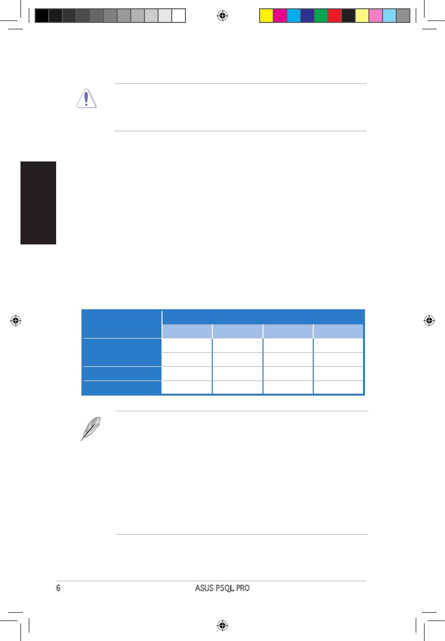
3. Mémoire Système
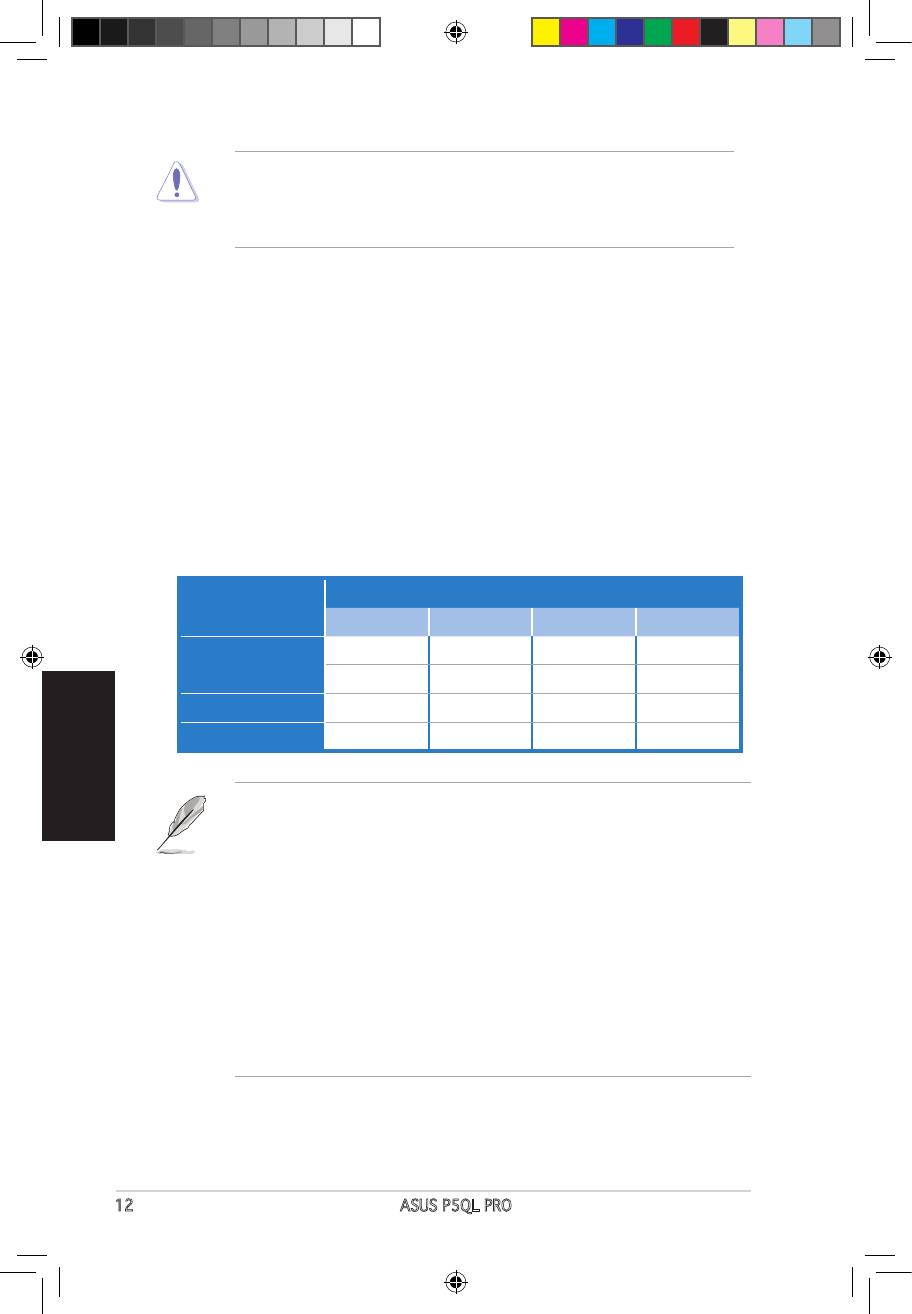
Vous pouvez installer des modules DIMM DDR2 non ECC non tamponnés
de 512 Mo, 1 Go, 2 Go et 4Go dans les socles DIMM en utilisant les
Emplacements
Mode
DIMM_A1 DIMM_A2 DIMM_B1 DIMM_B2
— — Occupé —
Single canal
Occupé — — —
Double canal (1)
Occupé —
Occupé
—
Double canal (2)
Occupé Occupé Occupé Occupé
installés par canal doit être identique (DIMM_A1 = DIMM_B1).
• Installez toujours des DIMM dotés de la même valeur CAS latency. Pour uneInstallez toujours des DIMM dotés de la même valeur CAS latency. Pour une
compatibilité optimale, il est recommandé d’acheter des modules mémoire
de même marque.
• Si vous utilisez un système d’exploitation Windows 32-bits (par exemple
Windows XP ou Vista 32-bits) ne supportant pas l’extension d’adresse
physique, le système allouera un certain montant d’espace mémoire aux
périphériques système.
• Il est recommandé de n’installer qu’un maximum de 3Go de mémoire système
lors de l’utilisation d’un système d’exploitation Windows 32-bits ne supportant
pas l’extension d’adresse physique. L’excédent de mémoire ne posera aucun
problème, toutefois, le système ne pourra pas ni détecter ni utiliser cet
excédent de mémoire.
A3782_P5QL PRO.indb 3 6/2/08 1:39:08 PM
4. Informations du BIOS
Français
La ROM Flash sur la carte mère contient un BIOS. Vous pouvez mettre à jour les
du BIOS. Les écrans BIOS comprennent les clés de navigation et une courte aide
en ligne pour vous guider. Si vous rencontrez des problèmes liés au système ou si
les Paramètres de Réglage Par Défaut. Rendez visite au site web d’ASUS (www.
asus.com) pour obtenir les mises à jour.
Pour accéder au Setup lors du démarrage:
Pressez <Suppr> lors du Test Automatique de Démarrage (POST : Power-On Self
Test ). Si vous ne pressez pas la touche <Suppr>, le POST continuera son programme
de test.
Pour accéder au Setup après le POST:
• Redémarrez le système en pressant <Ctrl> + <Alt> + <Suppr>, puis pressez
<Suppr> lors du POST, ou
• Pressez le bouton de réinitialisation situé sur le châssis puis pressez <Suppr>
lors du POST, ou
• Eteignez et rallumez le système puis pressez <Suppr> lors du POST.
Pour mettre à jour le BIOS avec AFUDOS:
Rebootez le système lorsque la mise à jour sera terminée.
Pour mettre à jour le BIOS avec ASUS EZ Flash 2:
Bootez le système puis pressez <Alt> + <F2> lors du POST pour lancer EZ Flash 2.
Flash 2 effectuera le processus de mise à jour du BIOS et rebootera automatiquement
le système une fois qu’il aura terminé.
Pour récupérer le BIOS avec CrashFree BIOS 3:
Démarrez le système. Si le BIOS est corrompu, l’outil de récupération automatique de
CrashFree BIOS 3 vous demande d’insérer une disquette, le DVD de support ou un
le système une fois le BIOS récupéré.
5. Informations sur le DVD technique
®
Cette carte mère supporte les systèmes d’exploitation Windows
XP / Vista. Installez
toujours la dernière version d’OS et les mises à jour correspondantes de manière à
maximiser les caractéristiques de votre hardware.
Le DVD technique livré avec la carte mère contient des logiciels et de nombreux
pilotes et utilitaires qui améliorent les fonctions de la carte mère. Pour utiliser le DVD
technique, insérez-le simplement dans votre lecteur DVD-ROM. si Autorun est activé
ASSETUP.EXE dans le dossier BIN du DVD technique et double-cliquez dessus.
4
ASUS P5QL PRO
A3782_P5QL PRO.indb 4 6/2/08 1:39:09 PM
1. マザーボードのレイアウト
日
本
語
ASUS P5QL PRO 5
19.3cm (7.6in)
PS/2KBMS
PS2_USBPW56
T:Mouse
PS2_USBPW56
1
2
2
3
B:Keyboard
+5VSB
+5VSB
(D
e
fault)
USB56
ATX12V
LGA775
SPDIF_O1
USB34
USBPW1-4
1
2
2
3
+5VSB
+5VSB
LAN1_USB12
(D
e
fault)
AUDIO
Intel
DDR2 DIMMB1 (64 bit,240-pin module)
DDR2 DIMMB2 (64 bit,240-pin module)
P43
DDR2 DIMMA1 (64 bit,240-pin module)
DDR2 DIMMA2 (64 bit,240-pin module)
CHA_FAN
P5QL PRO
EATXPWR
30.5cm (12in)
USBPW1112
CPU_FAN
1
2
2
3
PWR_FAN
+5
V
+5VSB
PCIEX16
(D
e
fa
u
lt
)
ICS
PCIEX1_1
USBPW7-10
9LPRS916JGLF
1
2
2
3
+5
V
+5VSB
(Defau
lt
)
Super I/O
Intel
PCI1
ICH10
CLRTC
1 2 2 3
COM1
PCI2
Normal
Clear RTC
(Default)
CR2032 3V
4Mb
Lithium Cell
BIOS
CMOS Power
PCI3
PANEL
ALC
PLED SPEAKER
1200
88SE6102
Marvell
PLED+
PLED-
Ground
Ground
Speaker
+5V
PCIEX1_2
SB_PWR
SPDIF_OUT
USBPW1112
USBPW7-10
CLRTC
IDE_LED+
IDE_LED-
PWR
Ground
Reset
Ground
CD
AAFP
FLOPPY
USB1112 USB78 USB910
CHASSIS
PANEL
+IDE_LED
RESET
PWRSW
*
Requires an ATX power supply
2. CPUを取り付ける
®
Intel
プロセッサ(775-land パッケージ)を取り付ける手順
1. 親指でロードレバーを押し(A)、タブから外れるまで左に動かします(B)。
タブ
ソケット
キャップ
A
ロードレバー
B
ソケットボックスのこの面を
自分の方に向けます。
A3782_P5QL PRO.indb 5 6/2/08 1:39:12 PM
• ソケットピンの損傷防止のため、ソケットキャップはCPUの取り付けの際
以外は外さないでください。
• 返品等の際はキャップを取り付けた状態で送付してください。
• 製品保証サービスはソケットピンの破損・損傷には適用されません。
2. 矢印の方向に135°ほどロードレバーを持ち上げます。
3. ロードプレートを親指と人差し指で100°ほど持ち上げ、ロードプレートウィンド
ウからソケットキャップを押して取り外します。
4. CPUに書かれている金色の三角形がソケットの左下隅になるようにCPUをソケット
の上に載せます。このとき、ソケットの位置合わせキーは、CPUの溝にぴったり合わ
せる必要があります。
5. ロードプレートを閉じ、ロードレバーがタブに収まるまで押します。
3. システムメモリ
本マザーボードはこのセクションに記載の設定で unbeered Non-ECC DDR2 メモリ
(512MB、1GB、2GB 、4GB)を取り付けることができます。
スロット
モード
DIMM_A1 DIMM_A2 DIMM_B1 DIMM_B2
— — 使用 —
シングルチャンネル
使用 — — —
デュアルチャンネル(1)
使用 — 使用 —
デュアルチャンネル(2)
使用 使用 使用 使用
• デュアルチャンネルを使用するには、各チャンネルに取り付けるメモリの総容量
は同じでなければなりません。(DIMM_A1= DIMM_B1)
• 同じ CAS レイテンシー のメモリをご使用ください。また、同じベンダーのメモリ
の使用を推奨します。 DDR2メモリのQVL(Qualied Vendors List:推奨ベンダー
リスト)は次項に記載しました。
• PAE(Physical Address Extension)をサポートしない Windows 32 bit OS (例:
Windows Vista 32bit/Windows XP 32bit)をご使用の場合、システムは一定量
のメモリ空間をシステムデバイスに割り当てます。
• PAE をサポートしない Windows 32 bit OS をご使用の場合、3GB 以下のシステ
ムメモリのみを取り付けることをお勧めします。3GB 以上のメモリを取り付けて
も問題はありませんが、システムは超過分のメモリスペースを使用することがで
きず、表示されるメモリサイズは取り付けた物理メモリの合計サイズ以下です。
A3782_P5QL PRO.indb 6 6/2/08 1:39:13 PM
4. BIOS情報
マザーボードの Flash ROM には BIOS が組み込まれおり、 BIOS セットアップユーティ
リティで BIOS 情報の更新やパラメータの設定ができます。 BIOS 画面にはナビゲーシ
ョンキーと簡単なオンラインヘルプがあります。システムに問題がある場合や、設定変
更後にシステムが不安定になった場合は、デフォルトをロードしてください。更新の際
は ASUSの Web サイト (www.asus.co.jp) をご覧ください。
BIOSセットアップを実行する
パワーオンセルフテスト (POST) 中に <Delete> キーを押してください。 <Delete> キ
ーを押さなければ、 POST はテストルーチンを続けます。
POST 後のセットアップ
• <Ctrl + Alt + Delete> キーを押してシステムを再起動し、 POST 中に <Delete> キ
ーを押します。
または
• ケースのリセットボタンを押し、 POST 中に <Delete> キーを押します。
または
• システムを一度オフにしれから再度オンにし、 POST 画面で <Delete> キーを押し
ます。
AFUDOSツールでBIOSを更新する:
最新の BIOS ファイルを保存したフロッピーディスクからシステムを起動します。DOS
プロンプトが表示されたら、 afudos/i<lename.rom> と入力し <Enter> キーを押
します。更新が完了したらシステムを再起動します。
ASUSEZFlash2ツールでBIOSを更新する:
システムを起動し、 POST 中に <Alt + F2> キーを押すと EZ Flash 2 が起動します。最
新の BIOS ファイルを保存したフロッピーディスク(またはUSB フラッシュメモリ)をシ
ステムに取り付けてください。EZ Flash 2 は BIOS 更新を実行し、完了するとシステムは
自動的に再起動します。
CrashFreeBIOS3でBIOSを修復する
システムを起動します。BIOS に問題がある場合、CrashFree BIOS 3 自動修復ツールが
それを検出し、オリジナルか最新の BIOS ファイルが保存されたフロッピーディスクま
たは DVD、 USB フラッシュメモリを挿入するよう画面にメッセージが表示されます。
BIOS が修復されたらシステムを再起動してください。
5. ソフトウェア、サポートDVD情報
®
本マザーボードは Windows
XP / Vista operating system (OS). をサポートしていま
す。ハードウェアの機能を最大限に利用するため、常に最新の OS バージョンと関連す
るアップデートを使用してください。
マザーボードに付属のサポート DVD にはマザーボードの利用に役立つソフトウェ
アと各ユーティリティ用のドライバが入っています。サポート DVD を使用する際は、
DVD-ROM ドライブに DVD を挿入してください。オートラン機能が有効であれば自動
で開始画面と設定メニューが表示され、無効の場合は直接サポート DVD の BIN フォ
ルダ内の ASSETUP.EXE ファイルをダブルクリックしてください。
A3782_P5QL PRO.indb 7 6/2/08 1:39:14 PM
1. 마더보드레이아웃
19.3cm (7.6in)
PS/2KBMS
PS2_USBPW56
T:Mouse
PS2_USBPW56
1
2
2
3
B:Keyboard
+5VSB
+5VSB
(D
e
fault)
USB56
ATX12V
LGA775
SPDIF_O1
USB34
USBPW1-4
1
2
2
3
+5VSB
+5VSB
LAN1_USB12
(D
e
fault)
AUDIO
Intel
DDR2 DIMMB1 (64 bit,240-pin module)
DDR2 DIMMB2 (64 bit,240-pin module)
P43
DDR2 DIMMA1 (64 bit,240-pin module)
DDR2 DIMMA2 (64 bit,240-pin module)
CHA_FAN
P5QL PRO
EATXPWR
30.5cm (12in)
USBPW1112
CPU_FAN
1
2
2
3
PWR_FAN
+5
V
+5VSB
PCIEX16
(D
e
fa
u
lt
)
ICS
PCIEX1_1
USBPW7-10
9LPRS916JGLF
1
2
2
3
+5
V
+5VSB
(Defau
lt
)
Super I/O
Intel
PCI1
ICH10
CLRTC
1 2 2 3
COM1
PCI2
Normal
Clear RTC
(Default)
CR2032 3V
4Mb
Lithium Cell
BIOS
CMOS Power
PCI3
PANEL
ALC
PLED SPEAKER
1200
88SE6102
Marvell
PLED+
PLED-
Ground
Ground
Speaker
+5V
PCIEX1_2
SB_PWR
SPDIF_OUT
USBPW1112
USBPW7-10
CLRTC
IDE_LED+
IDE_LED-
PWR
Ground
Reset
Ground
CD
AAFP
FLOPPY
USB1112 USB78 USB910
CHASSIS
PANEL
+IDE_LED
RESET
PWRSW
*
Requires an ATX power supply
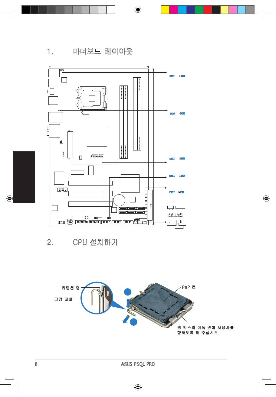
2. CPU설치하기
®
다음의절차를따라775-land패키지에Intel
processor를설치하여주십시오.
1. 엄지손가락(A)으로고정레버를눌러주신후,리텐션탭에서떨어질때까지
좌측(B)으로이동하여주십시오.
리텐션탭
PnP캡
A
고정레버
B
캠박스의이쪽면이사용자를
향하도록해주십시오.
A3782_P5QL PRO.indb 8 6/2/08 1:39:17 PM
• 소켓핀의손상을방지하기위해CPU를설치하지않을때는PnP캡을제
거하지마십시오.
• 제품반품시를대비하여캡을보관하여주십시오.
• 제품보증은손상된소켓핀을포함하지않습니다.
2. 고정레버를화살표방향으로135°각도올려주십시오.
3. 엄지와검지손가락을사용하여고정플레이트를100°각도로올려주신후,
고정플레이트창에위치한PnP캡을눌러제거하여주십시오.
4. 소켓위에CPU를위치시킨후,금색삼각마크가소켓의좌측하단에위치하
였는지확인해주십시오.소켓정렬키는CPU노치에올바르게맞아야합니
다.
5. 고정플레이트를닫고,고정레버가리텐션탭에고정되도록고정레버를내
려주십시오.
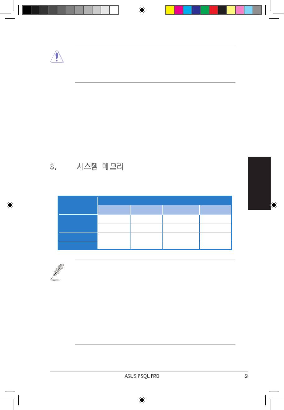
3. 시스템메모리
모드 소켓
DIMM_A1 DIMM_A2 DIMM_B1 DIMM_B2
— — Populated —
싱글채널
Populated — — —
듀얼채널(1) Populated — Populated —
듀얼채널(2) Populated Populated Populated Populated
•
•
•
•
A3782_P5QL PRO.indb 9 6/2/08 1:39:19 PM
4. BIOS정보
•
•
•
한국어
5. 소프트웨어지원DVD정보
®
10 ASUS P5QL PRO
A3782_P5QL PRO.indb 10 6/2/08 1:39:19 PM
1. ส่วนต่างๆ ของเมนบอร์ด
ไทย
ASUS P5QL PRO 11
19.3cm (7.6in)
PS/2KBMS
PS2_USBPW56
T:Mouse
PS2_USBPW56
1
2
2
3
B:Keyboard
+5VSB
+5VSB
(D
e
fault)
USB56
ATX12V
LGA775
SPDIF_O1
USB34
USBPW1-4
1
2
2
3
+5VSB
+5VSB
LAN1_USB12
(D
e
fault)
AUDIO
Intel
DDR2 DIMMB1 (64 bit,240-pin module)
DDR2 DIMMB2 (64 bit,240-pin module)
P43
DDR2 DIMMA1 (64 bit,240-pin module)
DDR2 DIMMA2 (64 bit,240-pin module)
CHA_FAN
P5QL PRO
EATXPWR
30.5cm (12in)
USBPW1112
CPU_FAN
1
2
2
3
PWR_FAN
+5
V
+5VSB
PCIEX16
(D
e
fa
u
lt
)
ICS
PCIEX1_1
USBPW7-10
9LPRS916JGLF
1
2
2
3
+5
V
+5VSB
(Defau
lt
)
Super I/O
Intel
PCI1
ICH10
CLRTC
1 2 2 3
COM1
PCI2
Normal
Clear RTC
(Default)
CR2032 3V
4Mb
Lithium Cell
BIOS
CMOS Power
PCI3
PANEL
ALC
PLED SPEAKER
1200
88SE6102
Marvell
PLED+
PLED-
Ground
Ground
Speaker
+5V
PCIEX1_2
SB_PWR
SPDIF_OUT
USBPW1112
USBPW7-10
CLRTC
IDE_LED+
IDE_LED-
PWR
Ground
Reset
Ground
CD
AAFP
FLOPPY
USB1112 USB78 USB910
CHASSIS
PANEL
+IDE_LED
RESET
PWRSW
*
Requires an ATX power supply
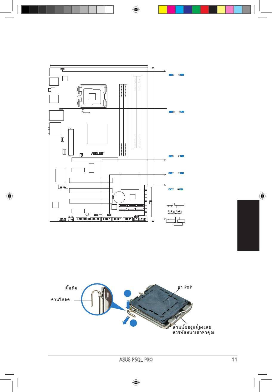
2. การติดตั้ง CPU
®
A
B
A3782_P5QL PRO.indb 11 6/2/08 1:39:22 PM
3. หน่วยความจำระบบ
ซ็อกเก็ต
โหมด
DIMM_A1 DIMM_A2 DIMM_B1 DIMM_B2
ซิงเกิลแชนเนล
ดูอัล-แชนเนล (1)
ดูอัล-แชนเนล (2)
A3782_P5QL PRO.indb 12 6/2/08 1:39:24 PM
4. ข้อมูล BIOS
•
•
5. ข้อมูลการสนับสนุนซอฟต์แวร์บน DVD
®
A3782_P5QL PRO.indb 13 6/2/08 1:39:24 PM
Indonesia
Bahasa
14 ASUS P5QL PRO
1. Layout motherboard
19.3cm (7.6in)
PS/2KBMS
PS2_USBPW56
T:Mouse
PS2_USBPW56
1
2
2
3
B:Keyboard
+5VSB
+5VSB
(D
e
fault)
USB56
ATX12V
LGA775
SPDIF_O1
USB34
USBPW1-4
1
2
2
3
+5VSB
+5VSB
LAN1_USB12
(D
e
fault)
AUDIO
Intel
DDR2 DIMMB1 (64 bit,240-pin module)
DDR2 DIMMB2 (64 bit,240-pin module)
P43
DDR2 DIMMA1 (64 bit,240-pin module)
DDR2 DIMMA2 (64 bit,240-pin module)
CHA_FAN
P5QL PRO
EATXPWR
30.5cm (12in)
USBPW1112
CPU_FAN
1
2
2
3
PWR_FAN
+5
V
+5VSB
PCIEX16
(D
e
fa
u
lt
)
ICS
PCIEX1_1
USBPW7-10
9LPRS916JGLF
1
2
2
3
+5
V
+5VSB
(Defau
lt
)
Super I/O
Intel
PCI1
ICH10
CLRTC
1 2 2 3
COM1
PCI2
Normal
Clear RTC
(Default)
CR2032 3V
4Mb
Lithium Cell
BIOS
CMOS Power
PCI3
PANEL
ALC
PLED SPEAKER
1200
88SE6102
Marvell
PLED+
PLED-
Ground
Ground
Speaker
+5V
PCIEX1_2
SB_PWR
SPDIF_OUT
USBPW1112
USBPW7-10
CLRTC
IDE_LED+
IDE_LED-
PWR
Ground
Reset
Ground
CD
AAFP
FLOPPY
USB1112 USB78 USB910
CHASSIS
PANEL
+IDE_LED
RESET
PWRSW
*
Requires an ATX power supply
2. Memasang CPU
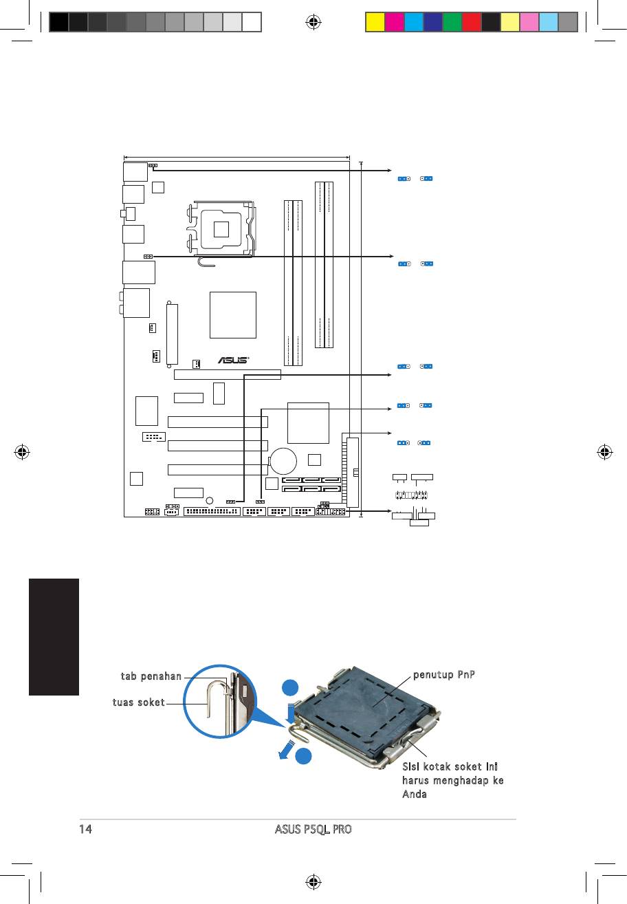
Ikuti langkah-langkah berikut ini untuk memasang CPU Intel pada soket 775.
1. Tekan tuas soket dengan ibu jari (A), kemudian pindahkan ke kiri (B)
hingga terlepas dari tab penahannya.
tab penahan
penutup PnP
A
tuas soket
B
Sisi kotak soket ini
harus menghadap ke
Anda
A3782_P5QL PRO.indb 14 6/2/08 1:39:28 PM
Bahasa
Indonesia
ASUS P5QL PRO 15
• Untuk mencegah kerusakan pada pin soket, jangan melepaskan penutup
PnP, kecuali ketika memasang CPU.
• Simpanlah penutupnya untuk pengembalian produk.
• Jaminan produk tidak meliputi kerusakan pada pin soket.
2. Angkat tuas soket sesuai arah tanda panah ke sudut 135 °.
3. Angkat pelat soket dengan ibu jari dan telunjuk ke sudut 100°,
kemudian buka penutup PnP untuk melepaskannya.
4. Letakkan CPU di atas soket, pastikan sudut CPU bertanda segitiga
emas berada pada bagian sudut kiri bawah soket. Masukkan CPU ke
dalam soket hingga terpasang dengan tepat.
5. Tutup pelat soket, kemudian dorong tuas soket hingga terpasang
dengan benar pada tab penahan.
3. Memori Sistem
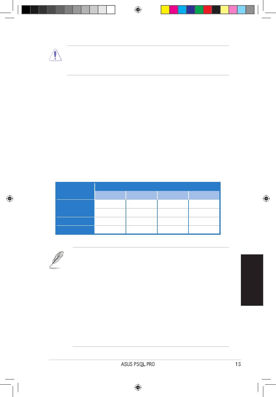
Anda dapat menginstal memori 512 MB, 1 GB, 2 GB dan 4 GB non-ECC
DDR2 DIMM unbuffered pada kedalam soket DIMM.
Soket
Mode
DIMM_A1 DIMM_A2 DIMM_B1 DIMM_B2
— — Terpasang —
Kanal Tunggal
Terpasang — — —
Kanal ganda (1) Terpasang — Terpasang —
Kanal ganda (2) Terpasang Terpasang Terpasang Terpasang
yang terpasang pada setiap kanal harus sama (DIMM_A1= DIMM_B1).
• Selalu pasang DIMM dengan CAS latency (CAS tersembunyi) yang sama.Selalu pasang DIMM dengan CAS latency (CAS tersembunyi) yang sama.
Untuk kesesuaian optimum, Anda disarankan untuk mendapatkan modul
pada halaman berikut untuk lebih jelasnya.
• Jika Anda menggunakan sistem operasi versi Windows 32-bit (misal, Windows
XP 32-bit, Vista 32-bit) tanpa dukungan Physical Address Extension (PAE)
(Ekstensi Alamat Fisik), sistem tersebut akan mengalokasikan sejumlah
ruang memori tertentu untuk peranti sistem.
• Kami menyarankan Anda hanya memasang memori sistem maksimum
sebesar 3GB ketika menggunakan sistem operasi versi Windows 32-bit tanpa
PAE. Memori terpasang yang melebihi 3GB tidak akan menyebabkan masalah
apapun, bagaimanapun juga sistem tersebut tidak dapat menggunakan
kelebihan ruang memori ini dan sistem akan menampilkan kurang dari ukuran
A3782_P5QL PRO.indb 15 6/2/08 1:39:29 PM
4. Informasi tentang BIOS
Flash ROM pada motherboard berisi BIOS. Anda dapat memperbarui informasi
Setup. Layar BIOS memiliki tombol navigasi dan bantuan ringkas online untuk
membantu Anda. Jika Anda mengalami masalah pada sistem atau jika sistem
menjadi tidak stabil setelah pengaturan diubah, aktifkan Setup Default. Untuk
pembaruan, kunjungi situs Web ASUS (www. asus.com).
Untuk membuka layar Setup saat pengaktifan awal:
Tekan <Delete> sewaktu Power-On Self Test (POST). Jika Anda tidak
menekan <Delete>, POST akan meneruskan test routine.
Untuk membuka layar Setup setelah POST:
• Aktifkan ulang sistem dengan menekan <Ctrl> + <Alt> + <Delete>,
kemudian tekan <Delete> sewaktu POST, atau
• Tekan tombol reset pada chassis, kemudian tekan <Delete> sewaktu POST, atau
• Matikan sistem dan hidupkan kembali, kemudian tekan <Delete> sewaktu POST
Memperbaharui BIOS dengan AFUDOS:
Pada DOS prompt (layar ketik DOS), ketik afudos /i<lename.rom> dan tekan
Enter. Reboot (Nyalakan-ulang) sistem ketika telah selesai memperbaharui.
Untuk memperbarui BIOS menggunakan ASUS EZ Flash 2:
Lakukan boot sistem, kemudian tekan <Alt> + <F2> sewaktu POST untuk
otomatis melakukan boot ulang sistem setelah proses tersebut selesai.
Untuk recovery BIOS menggunakan CrashFree BIOS 3:
Lakukan boot sistem. Jika BIOS rusak, program pemulihan otomatis
boot ulang sistem setelah BIOS kembali seperti semula.
Indonesia
5. Informasi tentang DVD pendukung
Bahasa
perangkat lunak
®
Motherboard ini mendukung OS (sistem operasi) Windows
XP / Vista.
Selalu instal versi OS terbaru beserta pembaruannya agar Anda dapat
DVD pendukung yang menyertai motherboard ini berisi perangkat lunak dan
Untuk mulai menggunakan DVD pendukung, cukup masukkan ke dalam
drive DVD-ROM. DVD akan secara otomatis menampilkan layar pembuka
dan menu penginstalan jika Autorun diaktifkan di komputer Anda. Jika layar
EXE dari folder BIN dalam DVD pendukung untuk menampilkan menu.
16 ASUS P5QL PRO
A3782_P5QL PRO.indb 16 6/2/08 1:39:29 PM
1. Sơ đồ bo mạch chủ
Tiếng Việt
ASUS P5QL PRO 17
19.3cm (7.6in)
PS/2KBMS
PS2_USBPW56
T:Mouse
PS2_USBPW56
1
2
2
3
B:Keyboard
+5VSB
+5VSB
(D
e
fault)
USB56
ATX12V
LGA775
SPDIF_O1
USB34
USBPW1-4
1
2
2
3
+5VSB
+5VSB
LAN1_USB12
(D
e
fault)
AUDIO
Intel
DDR2 DIMMB1 (64 bit,240-pin module)
DDR2 DIMMB2 (64 bit,240-pin module)
P43
DDR2 DIMMA1 (64 bit,240-pin module)
DDR2 DIMMA2 (64 bit,240-pin module)
CHA_FAN
P5QL PRO
EATXPWR
30.5cm (12in)
USBPW1112
CPU_FAN
1
2
2
3
PWR_FAN
+5
V
+5VSB
PCIEX16
(D
e
fa
u
lt
)
ICS
PCIEX1_1
USBPW7-10
9LPRS916JGLF
1
2
2
3
+5
V
+5VSB
(Defau
lt
)
Super I/O
Intel
PCI1
ICH10
CLRTC
1 2 2 3
COM1
PCI2
Normal
Clear RTC
(Default)
CR2032 3V
4Mb
Lithium Cell
BIOS
CMOS Power
PCI3
PANEL
ALC
PLED SPEAKER
1200
88SE6102
Marvell
PLED+
PLED-
Ground
Ground
Speaker
+5V
PCIEX1_2
SB_PWR
SPDIF_OUT
USBPW1112
USBPW7-10
CLRTC
IDE_LED+
IDE_LED-
PWR
Ground
Reset
Ground
CD
AAFP
FLOPPY
USB1112 USB78 USB910
CHASSIS
PANEL
+IDE_LED
RESET
PWRSW
*
Requires an ATX power supply
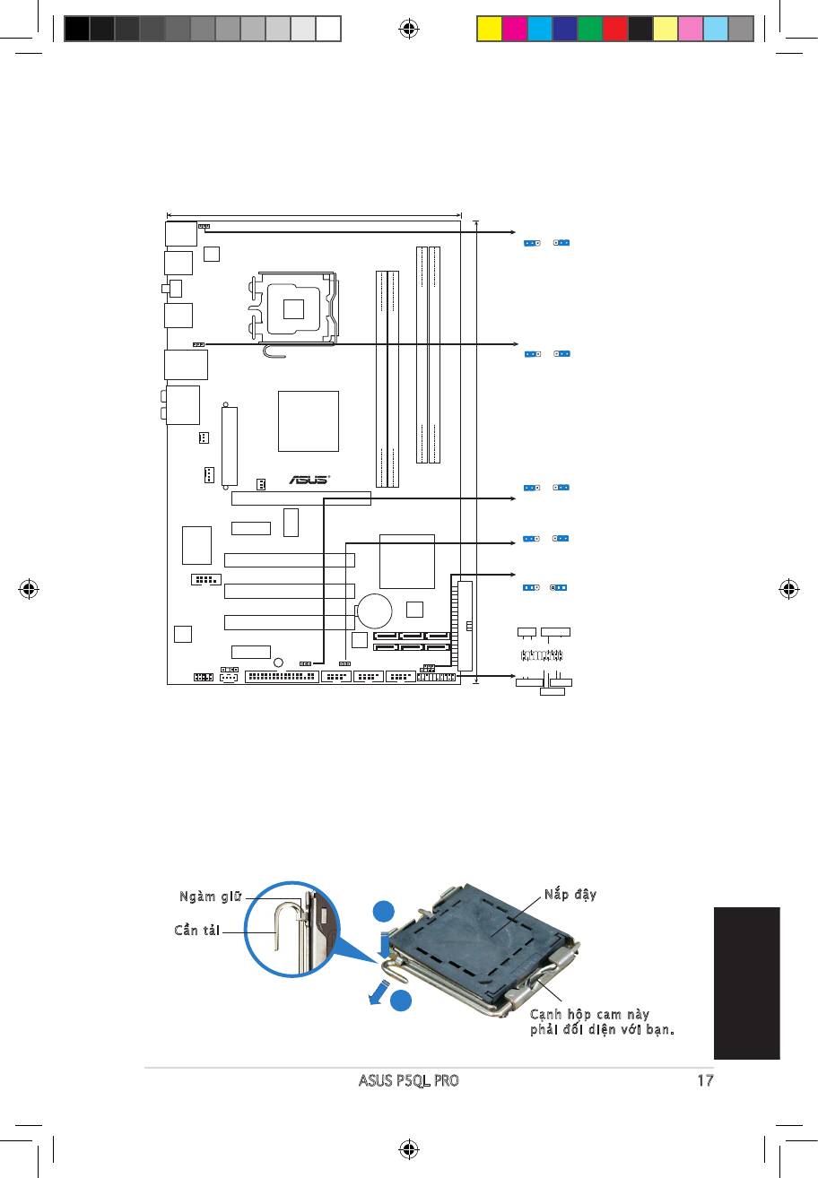
2. Lắp CPU
®
A
B
A3782_P5QL PRO.indb 17 6/2/08 1:39:33 PM
Tiếng Việt
18 ASUS P5QL PRO
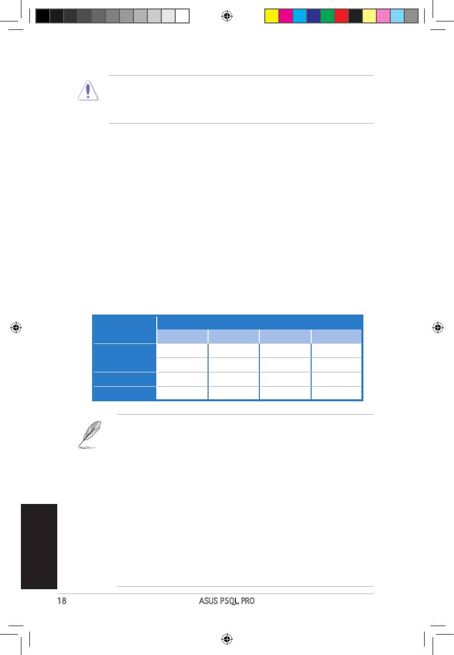
3. Bộ nhớ Hệ thống
Khe cắm
Chế độ
DIMM_A1 DIMM_A2 DIMM_B1 DIMM_B2
— — —
Kênh Đơn
— — —
Kênh đôi (1) — —
Kênh đôi (2)
A3782_P5QL PRO.indb 18 6/2/08 1:39:34 PM
Tiếng Việt
ASUS P5QL PRO 19
4. Thông tin BIOS
5. Thông tin DVD hỗ trợ phần mềm
®
A3782_P5QL PRO.indb 19 6/2/08 1:39:35 PM
1.
19.3cm (7.6in)
PS/2KBMS
PS2_USBPW56
T:Mouse
PS2_USBPW56
1
2
2
3
B:Keyboard
+5VSB
+5VSB
(D
e
fault)
USB56
ATX12V
LGA775
SPDIF_O1
USB34
USBPW1-4
1
2
2
3
+5VSB
+5VSB
LAN1_USB12
(D
e
fault)
AUDIO
Intel
DDR2 DIMMB1 (64 bit,240-pin module)
DDR2 DIMMB2 (64 bit,240-pin module)
P43
DDR2 DIMMA1 (64 bit,240-pin module)
DDR2 DIMMA2 (64 bit,240-pin module)
CHA_FAN
P5QL PRO
EATXPWR
30.5cm (12in)
USBPW1112
CPU_FAN
1
2
2
3
PWR_FAN
+5
V
+5VSB
PCIEX16
(D
e
fa
u
lt
)
ICS
PCIEX1_1
USBPW7-10
9LPRS916JGLF
1
2
2
3
+5
V
+5VSB
(Defau
lt
)
Super I/O
Intel
PCI1
ICH10
CLRTC
1 2 2 3
COM1
PCI2
Normal
Clear RTC
(Default)
CR2032 3V
4Mb
Lithium Cell
BIOS
CMOS Power
PCI3
PANEL
ALC
PLED SPEAKER
1200
88SE6102
Marvell
PLED+
PLED-
Ground
Ground
Speaker
+5V
PCIEX1_2
SB_PWR
SPDIF_OUT
USBPW1112
USBPW7-10
CLRTC
IDE_LED+
IDE_LED-
PWR
Ground
Reset
Ground
CD
AAFP
FLOPPY
USB1112 USB78 USB910
CHASSIS
PANEL
+IDE_LED
RESET
PWRSW
*
Requires an ATX power supply
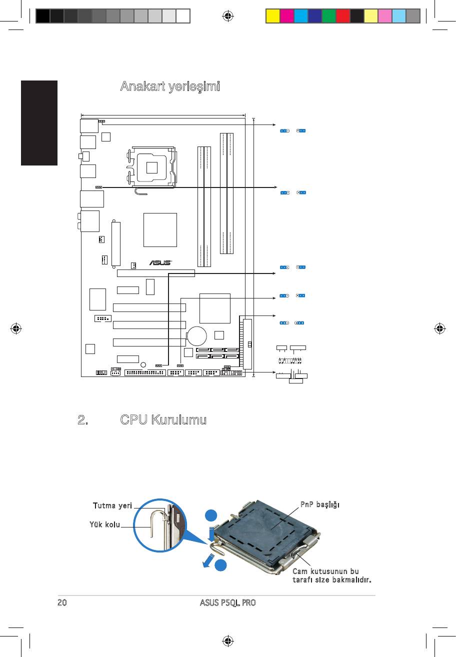
2. CPU Kurulumu
®
Intel
getirin.
Tutma yeri
A
B
Cam kutusunun bu
A3782_P5QL PRO.indb 20 6/2/08 1:39:38 PM
penceresinden itin.
kadar itin.
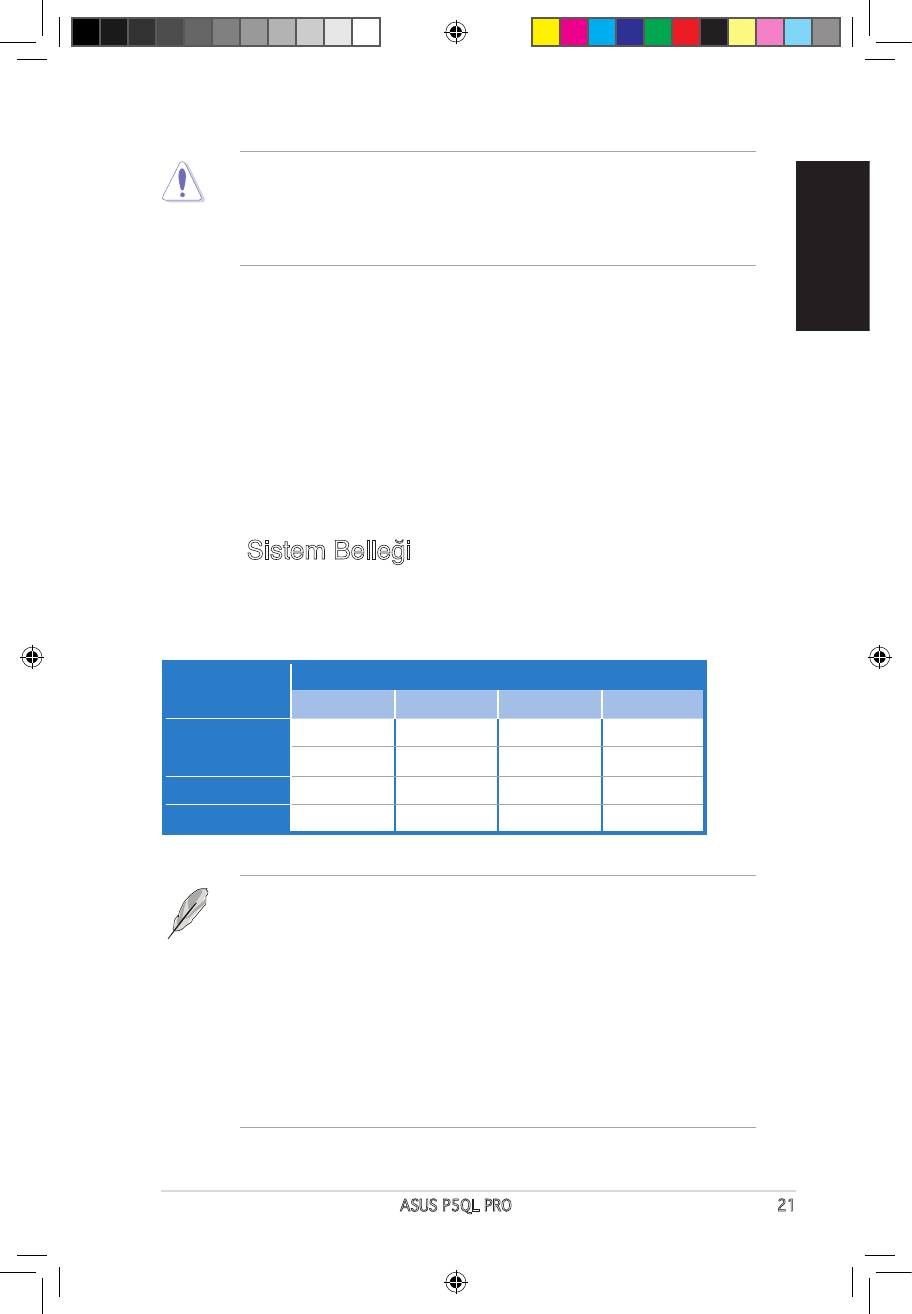
3.
DIMM soketlerine 512MB, 1 GB, 2 GB ve 4 GB tamponsuz ECC olmayan DDR2
DIMM’leri kurabilirsiniz.
Soketler
Mod
DIMM_A1 DIMM_A2 DIMM_B1 DIMM_B2
— — —
Tekli Kanal
— — —
Çiftli kanal (1) — —
Çiftli kanal (2)
A3782_P5QL PRO.indb 21 6/2/08 1:39:40 PM
4. BIOS bilgisi
Türkçe
sitesini (www. asus.com) ziyaret ediniz.
afudos /i<lename.rom> Enter
otomatik olarak yeniden boot eder.
BIOS’u Cras h F ree BIO S 3 ile k u r tarmak:
5.
®
Bu anakart Windows
22 ASUS P5QL PRO
A3782_P5QL PRO.indb 22 6/2/08 1:39:40 PM
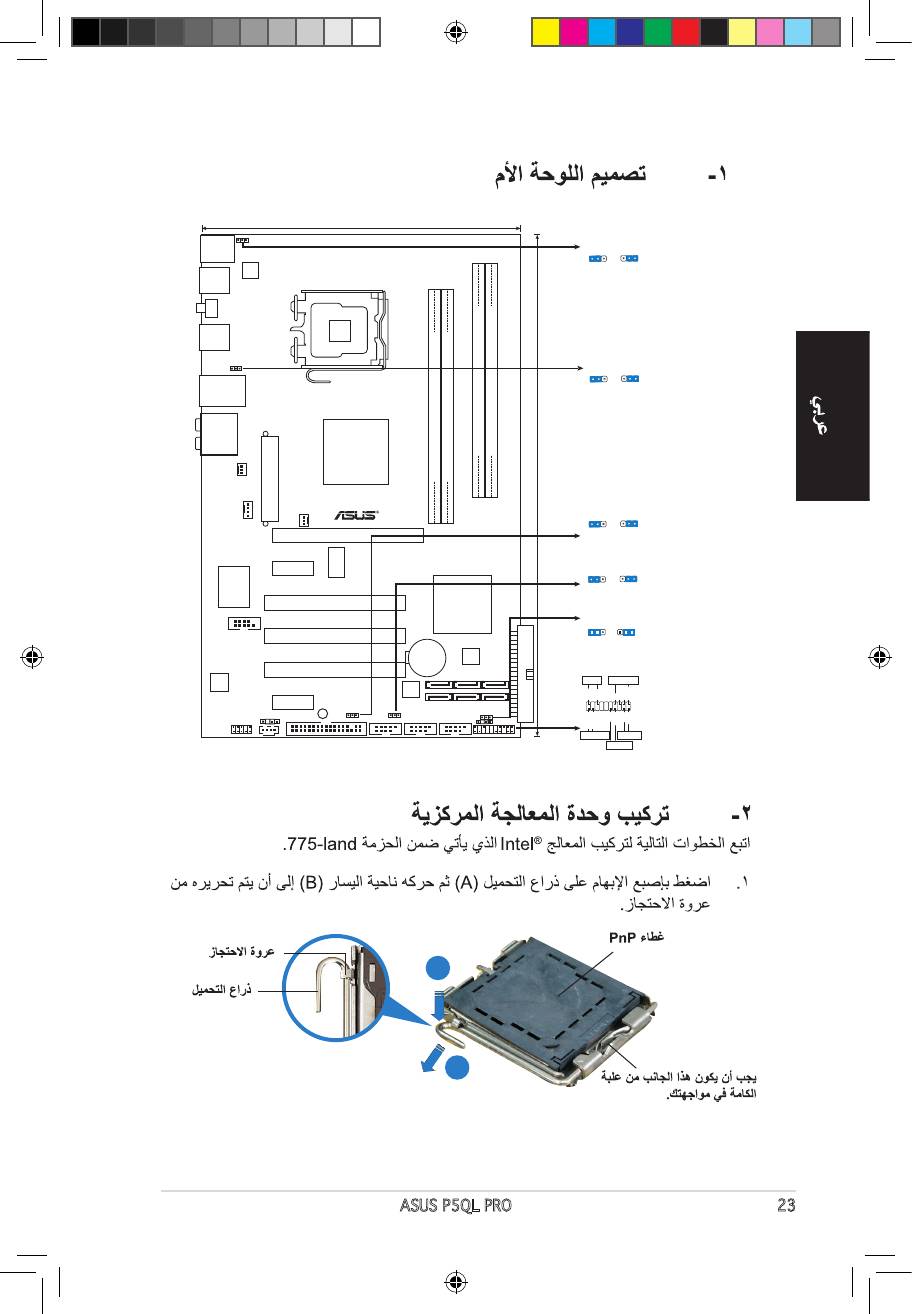
ASUS P5QL PRO 23
19.3cm (7.6in)
PS/2KBMS
PS2_USBPW56
T:Mouse
PS2_USBPW56
2
2
3
B:Keyboard
1
+5VSB
+5VSB
(D
e
fault)
USB56
ATX12V
LGA775
SPDIF_O1
USB34
USBPW1-4
1
2
2
3
+5VSB
+5VSB
LAN1_USB12
(D
e
fault)
AUDIO
Intel
DDR2 DIMMB1 (64 bit,240-pin module)
DDR2 DIMMB2 (64 bit,240-pin module)
P43
DDR2 DIMMA1 (64 bit,240-pin module)
DDR2 DIMMA2 (64 bit,240-pin module)
CHA_FAN
P5QL PRO
EATXPWR
30.5cm (12in)
USBPW1112
CPU_FAN
1
2
2
3
PWR_FAN
+5
V
+5VSB
PCIEX16
(D
e
fa
u
lt
)
ICS
PCIEX1_1
USBPW7-10
9LPRS916JGLF
1
2
2
3
+5
V
+5VSB
(Defau
lt
)
Super I/O
Intel
PCI1
ICH10
CLRTC
1 2 2 3
COM1
PCI2
Normal
Clear RTC
(Default)
CR2032 3V
4Mb
Lithium Cell
BIOS
CMOS Power
PCI3
PANEL
ALC
PLED SPEAKER
1200
88SE6102
Marvell
PLED+
PLED-
Ground
Ground
Speaker
+5V
PCIEX1_2
SB_PWR
SPDIF_OUT
USBPW1112
USBPW7-10
CLRTC
IDE_LED+
IDE_LED-
PWR
Ground
Reset
Ground
CD
AAFP
FLOPPY
USB1112 USB78 USB910
CHASSIS
PANEL
+IDE_LED
RESET
PWRSW
*
Requires an ATX power supply
A3782_P5QL PRO.indb 23 6/2/08 1:39:43 PM
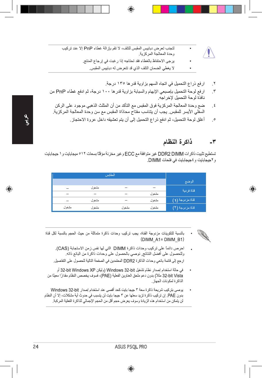
24 ASUS P5QL PRO
DIMM_B2 DIMM_B1 DIMM_A2 DIMM_A1
A3782_P5QL PRO.indb 24 6/2/08 1:39:46 PM
ASUS P5QL PRO 25
A3782_P5QL PRO.indb 25 6/2/08 1:39:46 PM
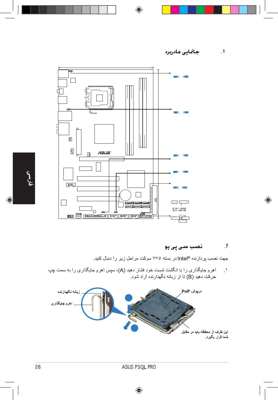
26 ASUS P5QL PRO
19.3cm (7.6in)
PS/2KBMS
PS2_USBPW56
T:Mouse
PS2_USBPW56
1
2
3
B:Keyboard
2
+5VSB
+5VSB
(D
e
fault)
USB56
ATX12V
LGA775
SPDIF_O1
USB34
USBPW1-4
1
2
2
3
+5VSB
+5VSB
LAN1_USB12
(D
e
fault)
AUDIO
Intel
DDR2 DIMMB1 (64 bit,240-pin module)
DDR2 DIMMB2 (64 bit,240-pin module)
P43
DDR2 DIMMA1 (64 bit,240-pin module)
DDR2 DIMMA2 (64 bit,240-pin module)
CHA_FAN
P5QL PRO
EATXPWR
30.5cm (12in)
USBPW1112
CPU_FAN
1
2
2
3
PWR_FAN
+5
V
+5VSB
PCIEX16
(D
e
fa
u
lt
)
ICS
PCIEX1_1
USBPW7-10
9LPRS916JGLF
1
2
2
3
+5
V
+5VSB
(Defau
lt
)
Super I/O
Intel
PCI1
ICH10
CLRTC
1 2 2 3
COM1
PCI2
Normal
Clear RTC
(Default)
CR2032 3V
4Mb
Lithium Cell
BIOS
CMOS Power
PCI3
PANEL
ALC
PLED SPEAKER
1200
88SE6102
Marvell
PLED+
PLED-
Ground
Ground
Speaker
+5V
PCIEX1_2
SB_PWR
SPDIF_OUT
USBPW1112
USBPW7-10
CLRTC
IDE_LED+
IDE_LED-
PWR
Ground
Reset
Ground
CD
AAFP
FLOPPY
USB1112 USB78 USB910
CHASSIS
PANEL
+IDE_LED
RESET
PWRSW
*
Requires an ATX power supply
A3782_P5QL PRO.indb 26 6/2/08 1:39:50 PM
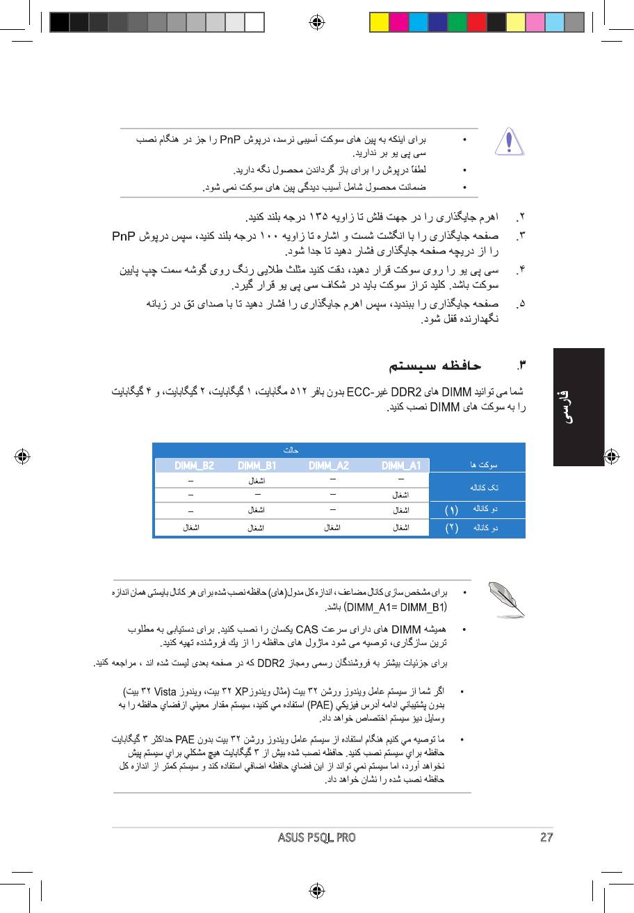
ASUS P5QL PRO 27
DIMM_B2 DIMM_B1 DIMM_A2 DIMM_A1
A3782_P5QL PRO.indb 27 6/2/08 1:39:52 PM
28 ASUS P5QL PRO
A3782_P5QL PRO.indb 28 6/2/08 1:39:53 PM
www.asus.com
A3782_P5QL PRO.indb 29 6/2/08 1:39:55 PM
- Производитель
- Asus
- Модель
- P5QL PRO
- Операционная система
-
- Windows 8.1
- Windows 8
- Windows 7
- Windows Vista
- Windows Server 2003
- Windows XP
- Windows 2000
- Linux
- MS-DOS
- Тип файла
-
- Инструкция
- Версия
-
C3782
32-bit
64-bit
Просмотреть содержимое архива
Вы нашли то, что искали?
Дополнительная информация
P5QL PRO user’s manual (Simplified Chinese)
Полезно
0 %
0
Commentary
Ваше имя
E4081
Second Edition V2
July 2008
Copyright © 2008 ASUSTeK COMPUTER INC. All Rights Reserved.
No part of this manual, including the products and software described in it, may be reproduced,
transmitted, transcribed, stored in a retrieval system, or translated into any language in any form or by any
means, except documentation kept by the purchaser for backup purposes, without the express written
permission of ASUSTeK COMPUTER INC. («ASUS»).
Product warranty or service will not be extended if: (1) the product is repaired, modified or altered, unless
such repair, modification of alteration is authorized in writing by ASUS; or (2) the serial number of the
product is defaced or missing.
ASUS PROVIDES THIS MANUAL «AS IS» WITHOUT WARRANTY OF ANY KIND, EITHER EXPRESS
OR IMPLIED, INCLUDING BUT NOT LIMITED TO THE IMPLIED WARRANTIES OR CONDITIONS OF
MERCHANTABILITY OR FITNESS FOR A PARTICULAR PURPOSE. IN NO EVENT SHALL ASUS, ITS
DIRECTORS, OFFICERS, EMPLOYEES OR AGENTS BE LIABLE FOR ANY INDIRECT, SPECIAL,
INCIDENTAL, OR CONSEQUENTIAL DAMAGES (INCLUDING DAMAGES FOR LOSS OF PROFITS,
LOSS OF BUSINESS, LOSS OF USE OR DATA, INTERRUPTION OF BUSINESS AND THE LIKE),
EVEN IF ASUS HAS BEEN ADVISED OF THE POSSIBILITY OF SUCH DAMAGES ARISING FROM ANY
DEFECT OR ERROR IN THIS MANUAL OR PRODUCT.
SPECIFICATIONS AND INFORMATION CONTAINED IN THIS MANUAL ARE FURNISHED FOR
INFORMATIONAL USE ONLY, AND ARE SUBJECT TO CHANGE AT ANY TIME WITHOUT NOTICE,
AND SHOULD NOT BE CONSTRUED AS A COMMITMENT BY ASUS. ASUS ASSUMES NO
RESPONSIBILITY OR LIABILITY FOR ANY ERRORS OR INACCURACIES THAT MAY APPEAR IN THIS
MANUAL, INCLUDING THE PRODUCTS AND SOFTWARE DESCRIBED IN IT.
Products and corporate names appearing in this manual may or may not be registered trademarks or
copyrights of their respective companies, and are used only for identification or explanation and to the
owners’ benefit, without intent to infringe.
ii