- Manuals
- Brands
- Asus Manuals
- Motherboard
- H110M-R
- Manual
-
Contents
-
Table of Contents
-
Bookmarks
Quick Links
Related Manuals for Asus H110M-R
Summary of Contents for Asus H110M-R
-
Page 1
H110M-R… -
Page 2
Product warranty or service will not be extended if: (1) the product is repaired, modified or altered, unless such repair, modification of alteration is authorized in writing by ASUS; or (2) the serial number of the product is defaced or missing. -
Page 3: Table Of Contents
Contents Safety information ………………iv About this guide ………………iv Package contents ………………vi H110M-R specifications summary …………vi Chapter 1: Product introduction Motherboard overview …………….1-1 Central Processing Unit (CPU) …………..1-7 System memory ………………1-8 Intel SBB support ………………. 1-9 ®…
-
Page 4: Safety Information
Safety information Electrical safety • To prevent electrical shock hazard, disconnect the power cable from the electrical outlet before relocating the system. • When adding or removing devices to or from the system, ensure that the power cables for the devices are unplugged before the signal cables are connected. If possible, disconnect all power cables from the existing system before you add a device.
-
Page 5
Refer to the following sources for additional information and for product and software updates. ASUS websites The ASUS website provides updated information on ASUS hardware and software products. Refer to the ASUS contact information. Optional documentation Your product package may include optional documentation, such as warranty flyers, that may have been added by your dealer. -
Page 6: Package Contents
Extreme Memory Profile (XMP) Memory * Refer to www.asus.com for the latest Memory QVL (Qualified Vendors List). ** Due to Intel® chipset limitation, DDR4 2133 MHz and higher memory modules on XMP mode will run at the maximum transfer rate of DDR4 2133 Mhz.
-
Page 7
— ASUS DIGI+ VRM — 3+1 Phase digital power design — ASUS DRAM Overcurrent Protection — Enhanced DRAM Overcurrent Protection — ASUS Stainless Steel Back I/O — 3X more durable corrosion-resistant coating Superb Performance UEFI BIOS — Most advanced options with fast response time… -
Page 8
7 (32-bit / 64-bit) * ® * Please refer to ASUS official website and download “Windows® 7 installation guide” and “ASUS EZ installer” to install Windows® 7. uATX form factor: 8.3 in. x 7.1 in. (21.08 cm x 18.03 cm) Form factor Specifications are subject to change without notice. -
Page 9: Motherboard Overview
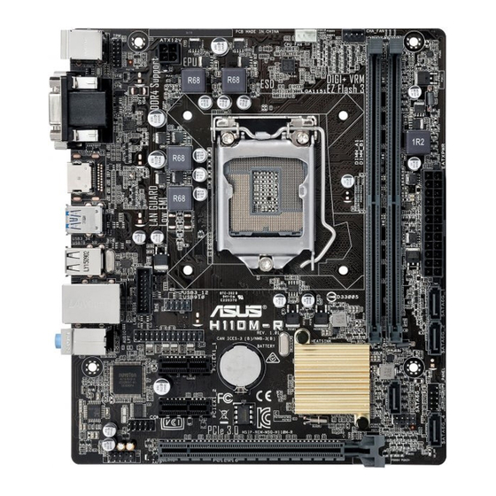
CPU_FAN KBMS CHA_FAN DIGI +VRM ATX12V 2168 Place this side towards HDMI the rear of the chassis LGA1151 USB3_34 USB78 USB3_12 Realtek 8111H USB910 LAN_USB56 H110M-R AUDIO PCIEX1_1 Intel ® Super H110 PCIEX1_2 128Mb BIOS AAFP PCIEX16 Scan the QR code to get the detailed pin definitions. ASUS H110M-R…
-
Page 10
Correctly orient the ATX power supply plugs into these connectors and push down firmly until the connectors completely fit. • For a fully configured system, we recommend that you use a power supply unit (PSU) that complies with ATX 12 V Specification 2.0 (or later version) and provides a minimum power of 350 W. • If you are uncertain about the minimum power supply requirement for your system, refer to the Recommended Power Supply Wattage Calculator at http://support.asus.com/PowerSupplyCalculator/ PSCalculator.aspx?SLanguage=en-us for details. Intel LGA1151 CPU socket ® Install Intel LGA1151 CPU into this surface mount LGA1151 socket, which is ® designed for 6th Generation Intel Core™ i7 / i5 / i3, Pentium , and Celeron ®… -
Page 11
Connect one end of the chassis intrusion sensor or switch cable to this header. The chassis intrusion sensor or switch sends a high-level signal to this header when a chassis component is removed or replaced. The signal is then generated as a chassis intrusion event. By default, the pin labeled “Chassis Signal” and “Ground” are shorted with a jumper cap. Remove the jumper caps only when you intend to use the chassis intrusion detection feature. Speaker connector (4-pin SPEAKER) This 4-pin connector is for the chassis-mounted system warning speaker. The speaker allows you to hear system beeps and warnings. Clear RTC RAM (2-pin CLRTC) CLRTC This header allows you to clear the CMOS RTC RAM data of the system setup information such as date, time, and system passwords. To erase the RTC RAM: PIN 1 Turn OFF the computer and unplug the power cord. Use a metal object such as a screwdriver to short the two pins. Plug the power cord and turn ON the computer. Hold down the <Del> key during the boot process and enter BIOS setup to re-enter data. If the steps above do not help, remove the onboard battery and short the two pins again to clear the CMOS RTC RAM data. After clearing the CMOS, reinstall the battery. ASUS H110M-R… -
Page 12
Front panel audio connector (10-1 pin AAFP) This connector is for a chassis-mounted front panel audio I/O module that supports either HD Audio or legacy AC`97 audio standard. Connect one end of the front panel audio I/O module cable to this connector. • We recommend that you connect a high-definition front panel audio module to this connector to avail of the motherboard’s high-definition audio capability. • If you want to connect a high-definition front panel audio module to this connector, set the Front Panel Type item in the BIOS setup to [HD Audio]. If you want to connect an AC’97 front panel audio module to this connector, set the item to [AC97]. By default, this connector is set to [HD Audio]. Serial port connector (10-1 pin COM) Connect the serial port module cable to this connector, then install the module to a slot opening at the back of the system chassis. PCI Express 3.0/2.0 x16 slot This motherboard supports PCI Express 3.0/2.0 x16 graphic cards complying with the PCI Express specifications. PCI Express 2.0 x1 slots This motherboard has two PCI Express 2.0 x1 slots that support PCI Express x1 network cards, SCSI cards, and other cards that comply with the PCI Express specifications. -
Page 13
Video Graphics Adapter (VGA) port. This 15-pin port is for a VGA monitor or other VGA-compatible devices. Activity Link Speed LAN (RJ-45) port. This port allows Gigabit connection to a Local Area Network (LAN) through a network hub. LAN port LAN port LED indications Activity/Link LED Speed LED Status Description Status Description No link 10Mbps connection Orange Linked ORANGE 100Mbps connection Orange (Blinking) Data activity GREEN 1Gbps connection Orange (Blinking Ready to wake up then steady) from S5 mode ASUS H110M-R… -
Page 14
Line In port (light blue). This port connects to the tape, CD, DVD player, or other audio sources. Line Out port (lime). This port connects to a headphone or a speaker. In the 4.1, 5.1 and 7.1-channel configurations, the function of this port becomes Front Speaker Out. Microphone port (pink). This port connects to a microphone. Refer to the audio configuration table for the function of the audio ports in 2.1, 4.1, 5.1, or 7.1-channel configuration. Audio 2.1, 4.1, 5.1, or 7.1-channel configuration Headset Port 4.1-channel 5.1-channel 7.1-channel 2.1-channel Light Blue (Rear panel) Line In Rear Speaker Out Rear Speaker Out Rear Speaker Out Lime (Rear panel) Line Out Front Speaker Out Front Speaker Out Front Speaker Out Pink (Rear panel) Mic In Mic In Bass/Center… -
Page 15: Central Processing Unit (Cpu)
Central Processing Unit (CPU) This motherboard comes with a surface mount LGA1151 socket designed for 6th Generation Intel Core™ i7 / i5 / i3, Pentium , and ® ® Celeron processors. ® Unplug all power cables before installing the CPU. • Ensure that you install the correct CPU designed for the LGA1151 socket only. DO NOT install a CPU designed for LGA1150, LGA1155 and LGA1156 sockets on the LGA1151 socket. • Upon purchase of the motherboard, ensure that the PnP cap is on the socket and the socket contacts are not bent. Contact your retailer immediately if the PnP cap is missing, or if you see any damage to the PnP cap/socket contacts/motherboard components. • Keep the cap after installing the motherboard. ASUS will process Return Merchandise Authorization (RMA) requests only if the motherboard comes with the cap on the LGA1151 socket. • The product warranty does not cover damage to the socket contacts resulting from incorrect CPU installation/removal, or misplacement/loss/incorrect removal of the PnP cap. Installing the CPU Apply the Thermal Interface Material to the CPU heatsink and CPU before you install the heatsink and fan if necessary. ASUS H110M-R…
-
Page 16: System Memory
(D/C) from the same vendor. Check with the vendor to get the correct memory modules. • According to Intel CPU spec, DIMM voltage below 1.35V is recommended to protect ® the CPU. • Due to the memory address limitation on 32-bit Windows OS, when you install 4GB ® or more memory on the motherboard, the actual usable memory for the OS can be about 3GB or less. For effective use of memory, we recommend that you do any of the following: Use a maximum of 3 GB system memory if you are using a 32-bit Windows OS. ® I nstall a 64-bit Windows OS if you want to install 4GB or more on the ® motherboard. F or more details, refer to the Microsoft support site at http://support.microsoft. ® com/kb/929605/en-us. Visit the ASUS website at www.asus.com for the latest QVL. Installing a DIMM To remove a DIMM Chapter 1: Product introduction…
-
Page 17: Intel ® Sbb Support
® the-box value for small business. Intel SBB requires MEI driver (AMT host software kit) to be installed and running. ® Platform requirements: • Windows 7 (32/64-bit) / Windows 8.1 (64-bit) / Windows 10 (64-bit) ® ® ® • PCH with 6th-generation Intel Core™ CPU (100 Series platforms) with 2MB Intel ® ® Management Engine 11.0 firmware installed CPU and chipsets requirements: • Intel Core™ i3 / i5 /i7 with one of these chipsets: H110, B150, H170, Q170 ® Other requirements: • Local Administrator rights on the target machine • Visit the ASUS website at www.asus.com for the latest CPU QVL (Qualified Vendors List). • Uninstall SBA4.0 before you install and upgrade to the latest version. ASUS H110M-R…
-
Page 18: Chapter 2: Bios Information
To enter BIOS Setup after POST: • Press <Ctrl>+<Alt>+<Del> simultaneously. • Press the reset button on the system chassis. • Press the power button to turn the system off then back on. Do this option only if you failed to enter BIOS Setup using the first two options. Using the power button, reset button, or the <Ctrl>+<Alt>+<Del> keys to force reset from a running operating system can cause damage to your data or system. We recommend you always shut down the system properly from the operating system. • The BIOS setup screens shown in this section are for reference purposes only, and may not exactly match what you see on your screen. • Visit the ASUS website at www.asus.com to download the latest BIOS file for this motherboard. • If the system becomes unstable after changing any BIOS setting, load the default settings to ensure system compatibility and stability. Select the Load Optimized Defaults item under the Exit menu or press hotkey F5. • If the system fails to boot after changing any BIOS setting, try to clear the CMOS and reset the motherboard to the default value. See section Motherboard overview for information on how to erase the RTC RAM. BIOS menu screen The BIOS setup program can be used under two modes: EZ Mode and Advanced Mode. Press <F7> to change between the two modes. ASUS H110M-R…
-
Page 19: Ez Mode
EZ Mode By default, the EZ Mode screen appears when you enter the BIOS setup program. The EZ Mode provides you an overview of the basic system information, and allows you to select the display language, system performance mode, fan profile and boot device priority. To access the Advanced Mode, click Advanced Mode(F7) or press <F7>. The default screen for entering the BIOS setup program can be changed. Refer to the Setup Mode item in section 2.8 Boot menu for details. Displays the system properties of the selected mode. Click <Enter> to Displays the CPU/motherboard switch EZ System Tuning modes temperature, CPU voltage output, Selects the display CPU/chassis fan speed, and SATA language of the BIOS information setup program…
-
Page 20: Advanced Mode
Q-Fan control Language Hot Keys Menu bar Configuration fields Scroll bar Last modified Sub-menu item General help settings Menu items Goes back to EZ Mode Search on FAQs Popup window Displays the CPU temperature, CPU and memory voltage output ASUS H110M-R…
-
Page 21: Exit Menu
Search on FAQ Move your mouse over this button to show a QR code. Scan this QR code with your mobile device to connect to the ASUS BIOS FAQ web page. You can also scan the QR code below. Exit menu The Exit menu items allow you to load the optimal default values for the BIOS items, and save or discard your changes to the BIOS items. Load Optimized Defaults This option allows you to load the default values for each of the parameters on the Setup menus. When you select this option or if you press <F5>, a confirmation window appears. Select OK to load the default values. Save Changes & Reset Once you are finished making your selections, choose this option from the Exit menu to ensure the values you selected are saved. When you select this option or if you press <F10>, a confirmation window appears. Select OK to save changes and exit. Discard Changes and Exit This option allows you to exit the Setup program without saving your changes. When you select this option or if you press <Esc>, a confirmation window appears. Select OK to discard changes and exit. Launch EFI Shell from USB drives This option allows you to attempt to launch the EFI Shell application (shellx64.efi) from one of the available USB devices. Chapter 2: Getting started…
-
Page 22: Appendices
Cet appareil est conforme aux normes CNR exemptes de licence d’Industrie Canada. Le fonctionnement est soumis aux deux conditions suivantes : (1) cet appareil ne doit pas provoquer d’interférences et (2) cet appareil doit accepter toute interférence, y compris celles susceptibles de provoquer un fonctionnement non souhaité de l’appareil. ASUS H110M-R…
-
Page 23
ASUS Recycling/Takeback Services ASUS recycling and takeback programs come from our commitment to the highest standards for protecting our environment. We believe in providing solutions for you to be able to responsibly recycle our products, batteries, other components as well as the packaging materials. -
Page 24
CE. das Diretivas da CE. Para mais detalhes, consulte a Declaração de Компания ASUS заявляет, что это устройство соответствует основным Conformidade CE. требованиям и другим соответствующим условиям европейских директив. Подробную информацию, пожалуйста, смотрите в декларации… -
Page 25: Asus Contact Information
+1-510-739-3777 +1-510-608-4555 Web site http://www.asus.com/us/ Technical Support Support fax +1-812-284-0883 Telephone +1-812-282-2787 Online support http://qr.asus.com/techserv ASUS COMPUTER GmbH (Germany and Austria) Address Harkort Str. 21-23, D-40880 Ratingen, Germany +49-2102-959931 Web site http://www.asus.com/de Online contact http://eu-rma.asus.com/sales Technical Support Telephone +49-2102-5789555 Support Fax…
-
Page 26
ASUS H110M-R…
Руководства пользователя
- Руководства пользователя
- Декларация соответствия
Версия —
15.18 MB
Windows_7_Setup_Guide_DVD
Версия E11428
1.7 MB
H110M-R User’s manual (English)
Версия DT162
3.81 MB
Intel 100 Series Ai Suite3 Manual(Traditional Chinese)
Версия DS162
2.64 MB
Intel 100 Series Ai Suite3 Manual(Spanish)
Версия DR162
2.15 MB
Intel 100 Series Ai Suite3 Manual(Russian)
Версия DK162
2.73 MB
Intel 100 Series Ai Suite3 Manual(Korean)
Версия DJ162
3.69 MB
Intel 100 Series Ai Suite3 Manual(Japanese)
Версия DG162
2.11 MB
Intel 100 Series Ai Suite3 Manual(German)
Версия DF162
3.54 MB
Intel 100 Series Ai Suite3 Manual(French)
Версия DE162
2.74 MB
Intel 100 Series Ai Suite3 Manual(English)
Материнская плата ASUS H110M-R Micro ATX DDR4 HDMI

Пересмотренное издание V2, март 2016 г. Авторское право © ASUSTeK COMPUTER INC, 2016. Все права защищены. Никакая часть данного руководства, включая описанные в нем продукты и программное обеспечение, не может быть воспроизведена, передана, переписана, сохранена в поисковой системе или переведена на любой язык в любой форме и любыми средствами, за исключением документации, хранимой покупателем для резервного копирования. целях без явного письменного разрешения ASUSTeK COMPUTER INC. («ASUS»).
Гарантия на продукт или обслуживание не будут продлены, если:
- Продукт ремонтируется, модифицируется или модифицируется, если такой ремонт, модификация или модификация не разрешены ASUS в письменной форме;
- Серийный номер продукта стерт или отсутствует.
ASUS ПРЕДОСТАВЛЯЕТ ДАННОЕ РУКОВОДСТВО «КАК ЕСТЬ» БЕЗ КАКИХ-ЛИБО ГАРАНТИЙ, ЯВНЫХ ИЛИ ПОДРАЗУМЕВАЕМЫХ, ВКЛЮЧАЯ, ПОМИМО ПРОЧЕГО, ПОДРАЗУМЕВАЕМЫЕ ГАРАНТИИ ИЛИ УСЛОВИЯ КОММЕРЧЕСКОЙ ПРИГОДНОСТИ ИЛИ ПРИГОДНОСТИ ДЛЯ ОПРЕДЕЛЕННОЙ ЦЕЛИ. НИ ПРИ КАКИХ ОБСТОЯТЕЛЬСТВАХ КОМПАНИЯ ASUS, ЕЕ ДИРЕКТОРЫ, ДОЛЖНОСТНЫЕ ЛИЦА, СОТРУДНИКИ ИЛИ АГЕНТЫ НЕ НЕСУТ ОТВЕТСТВЕННОСТИ ЗА ЛЮБОЙ КОСВЕННЫЙ, СПЕЦИАЛЬНЫЙ, СЛУЧАЙНЫЙ ИЛИ КОСВЕННЫЙ УЩЕРБ (ВКЛЮЧАЯ УЩЕРБ В ОТНОШЕНИИ ПРИБЫЛИ, ПОТЕРЮ БИЗНЕСА, ПОТЕРЮ ИСПОЛЬЗОВАНИЯ ИЛИ ДАННЫХ, ПЕРЕРЫВ ДЕЯТЕЛЬНОСТИ И ТАКОЕ), ДАЖЕ ЕСЛИ КОМПАНИИ ASUS БЫЛО ИЗВЕСТНО О ВОЗМОЖНОСТИ ТАКОГО ПОВРЕЖДЕНИЯ В СВЯЗИ С ЛЮБЫМ ДЕФЕКТОМ ИЛИ ОШИБКОЙ В ДАННОМ РУКОВОДСТВЕ ИЛИ ПРОДУКТЕ.
ТЕХНИЧЕСКИЕ ХАРАКТЕРИСТИКИ И ИНФОРМАЦИЯ, СОДЕРЖАЩИЕСЯ В ДАННОМ РУКОВОДСТВЕ, ПРЕДНАЗНАЧЕНЫ ТОЛЬКО ДЛЯ ИНФОРМАЦИОННОГО ИСПОЛЬЗОВАНИЯ, МОГУТ БЫТЬ ИЗМЕНЕНЫ В ЛЮБОЕ ВРЕМЯ БЕЗ ПРЕДВАРИТЕЛЬНОГО УВЕДОМЛЕНИЯ, И НЕ ДОЛЖНЫ БЫТЬ ОБЯЗАТЕЛЬНЫ ASUS. ASUS НЕ НЕСЕТ НИКАКОЙ ОТВЕТСТВЕННОСТИ ЗА ЛЮБЫЕ ОШИБКИ ИЛИ НЕТОЧНОСТИ, КОТОРЫЕ МОГУТ ОТЛИЧАТЬСЯ В ДАННОМ РУКОВОДСТВЕ, ВКЛЮЧАЯ ОПИСАНИЕ ПРОДУКТОВ И ПРОГРАММНОГО ОБЕСПЕЧЕНИЯ.
Названия продуктов и компаний, представленные в этом руководстве, могут быть или не быть зарегистрированными товарными знаками или авторскими правами соответствующих компаний и использоваться только для идентификации или объяснения и в интересах владельцев без намерения нарушить авторские права.
Предложение предоставить исходный код определенного программного обеспечения
Этот продукт содержит защищенное авторским правом программное обеспечение, которое лицензируется по Стандартной общественной лицензии («GPL»), в рамках Стандартной общественной лицензии ограниченного применения («LGPL») и / или других лицензий на бесплатное программное обеспечение с открытым исходным кодом. Такое программное обеспечение в этом продукте распространяется без каких-либо гарантий в пределах, разрешенных применимым законодательством. Копии этих лицензий включены в этот продукт.
Если применимая лицензия дает вам право на исходный код такого программного обеспечения и / или другие дополнительные данные, вы можете получить их в течение трех лет после нашей последней поставки продукта, либо
- бесплатно, скачав с http://support.asus.com/download
- на стоимость воспроизведения и доставки, которая зависит от предпочтительного перевозчика и места, куда вы хотите отправить его, отправив запрос по адресу:
ASUSTeK Computer Inc. Юридический отдел 15 Li Te Rd., Beitou, Taipei 112 Taiwan В своем запросе укажите название, номер модели и версию, как указано в поле «О продукте», для которого вы хотите получить соответствующий источник код и ваши контактные данные, чтобы мы могли согласовать с вами сроки и стоимость пересылки. Исходный код будет распространяться БЕЗ КАКИХ-ЛИБО ГАРАНТИЙ и под той же лицензией, что и соответствующий двоичный/объектный код. Это предложение действительно для всех, кто получил эту информацию.
ASUSTeK стремится предоставить полный исходный код в соответствии с требованиями различных лицензий на бесплатное программное обеспечение с открытым исходным кодом. Однако, если у вас возникнут какие-либо проблемы с получением полного соответствующего исходного кода, мы будем очень признательны, если вы отправите нам уведомление на адрес электронной почты. gpl@asus.com, указав продукт и описав проблему (НЕ присылайте на этот адрес электронной почты большие вложения, такие как архивы исходного кода и т. д.).
Информация по технике безопасности
Электрическая безопасность
- Во избежание поражения электрическим током отключите кабель питания от электрической розетки перед перемещением системы.
- При добавлении или удалении устройств в систему или из системы убедитесь, что силовые кабели для устройств отключены, прежде чем подключать сигнальные кабели. Если возможно, отключите все кабели питания от существующей системы перед добавлением устройства.
- Перед подключением или отключением сигнальных кабелей от материнской платы убедитесь, что все кабели питания отключены.
- Перед использованием адаптера или удлинителя обратитесь за профессиональной помощью. Эти устройства могут нарушить цепь заземления.
- Убедитесь, что ваш блок питания настроен на правильную громкость.tagе в вашем районе. Если вы не уверены в объемеtagе используемой электрической розетки, обратитесь в местную энергетическую компанию.
- Если блок питания сломан, не пытайтесь починить его самостоятельно. Обратитесь к квалифицированному специалисту по обслуживанию или к продавцу.
Безопасность операций
- Перед установкой материнской платы и добавлением компонентов внимательно прочтите все руководства, идущие в комплекте.
- Перед использованием продукта убедитесь, что все кабели правильно подключены и силовые кабели не повреждены. Если вы обнаружите какое-либо повреждение, немедленно обратитесь к вашему дилеру.
- Во избежание короткого замыкания держите скрепки, винты и скобы подальше от разъемов, разъемов, розеток и схем.
- Избегайте попадания пыли, влажности и экстремальных температур. Не размещайте продукт в местах, где он может подвергнуться воздействию влаги.
- Поставьте изделие на устойчивую поверхность.
- Если у вас возникнут технические проблемы с продуктом, обратитесь к квалифицированному специалисту по обслуживанию или к продавцу.
Об этом руководстве
Это руководство пользователя содержит информацию, необходимую для установки и настройки материнской платы.
Как организовано это руководство
Это руководство состоит из следующих частей:
- Глава 1: Внедрение продукции
В этой главе описываются функции материнской платы и поддерживаемые ею новые технологии. Он включает описание переключателей, перемычек и разъемов на материнской плате. - Глава 2: Информация о BIOS
В этой главе обсуждается изменение системных настроек через меню настройки BIOS. Также предоставляются подробные описания параметров BIOS.
Где найти дополнительную информацию
Обратитесь к следующим источникам для получения дополнительной информации и обновлений продукта и программного обеспечения.
- ASUS webместа
ASUS webНа сайте представлена обновленная информация об аппаратной и программной продукции ASUS. См. Контактную информацию ASUS. - Дополнительная документация
В комплект поставки вашего продукта может входить дополнительная документация, например гарантийные листки, которые, возможно, были добавлены вашим дилером. Эти документы не входят в стандартный пакет.
Условные обозначения, используемые в этом руководстве
Чтобы обеспечить правильное выполнение определенных задач, обратите внимание на следующие символы, используемые в этом руководстве.
ОПАСНО / ПРЕДУПРЕЖДЕНИЕ: Информация о том, как избежать травм при выполнении задания.
ВНИМАНИЕ: Информация по предотвращению повреждения компонентов при выполнении задачи
ВАЖНО: Инструкции, которым вы ДОЛЖНЫ следовать, чтобы выполнить задачу.
ПРИМЕЧАНИЕ: Советы и дополнительная информация, которые помогут вам выполнить задачу.
книгопечатание
- Жирный текст Указывает меню или элемент для выбора.
- Курсив Используются для выделения слова или фразы.
- Клавиши, заключенные в знаки меньше и больше, означают, что вы должны нажать заключенную в них клавишу. Бывшийampле: означает, что вы должны нажать клавишу Enter или Return.
- + + Если вам необходимо нажать две или более клавиши одновременно, клавиша
имена связаны знаком плюс (+).
Комплект поставки
Проверьте упаковку материнской платы на наличие следующих предметов.
- Материнская плата Материнская плата ASUS H110M-R
- Кабели 2 x Кабели Serial ATA 6.0 Гбит/с
- Аксессуары 1 х I / O Shield
- Заявление DVD 1 х поддержка DVD
- Документация 1 х Руководство пользователя
Краткое описание спецификаций


Внедрение продукции
Материнская плата надview
- Прежде чем прикасаться к какому-либо компоненту, отключите шнур питания от розетки.
- Перед работой с компонентами наденьте заземленный браслет или прикоснитесь к надежно заземленному или металлическому предмету, например к корпусу блока питания, чтобы не повредить их статическим электричеством.
- Перед установкой или удалением любого компонента убедитесь, что блок питания ATX выключен или шнур питания отсоединен от блока питания. Несоблюдение этого правила может привести к серьезному повреждению материнской платы, периферийных устройств или компонентов.
- Перед установкой или извлечением материнской платы отключите шнур питания. Невыполнение этого требования может привести к травмам и повреждению компонентов материнской платы.


Отсканируйте QR-код, чтобы получить подробные определения контактов.

- Разъем TPM (14-1-контактный TPM)
Этот соединитель поддерживает систему доверенного платформенного модуля (TPM), которая может безопасно хранить ключи, цифровые сертификаты, пароли и данные. Система TPM также помогает повысить безопасность сети, защищает цифровые идентификаторы и обеспечивает целостность платформы. - Разъемы питания ATX (24-контактный EATXPWR, 4-контактный ATX12V)
Правильно сориентируйте штекеры блока питания ATX в этих разъемах и с усилием надавите на них, чтобы разъемы полностью встали на место.- Для полностью сконфигурированной системы рекомендуется использовать блок питания (БП), соответствующий спецификации ATX 12 В 2.0 (или более поздней версии) и обеспечивающий минимальную мощность 350 Вт.
- Если вы не уверены в минимальном требовании к электропитанию
для вашей системы см. рекомендуемую мощность блока питания.tage Калькулятор на http://support.asus.com/PowerSupplyCalculator/PSCalculator.aspx?SLanguage=en-us для получения информации.
- Сокет процессора Intel® LGA1151
Установите процессор Intel® LGA1151 в этот разъем LGA1151 для поверхностного монтажа, который предназначен для процессоров Intel® Core™ i6 / i7 / i5 3-го поколения, Pentium® и Celeron®.
Для получения дополнительной информации обратитесь к Центральному процессору (ЦП). - Разъемы вентилятора процессора и корпуса (4-контактный CPU_FAN, 4-контактный CHA_FAN)
Подключите кабели вентилятора к разъемам вентилятора на материнской плате, убедившись, что черный провод каждого кабеля совпадает с контактом заземления разъема.
Предупреждение Не забудьте подключить кабели вентилятора к разъемам вентилятора. Недостаточный поток воздуха внутри системы может привести к повреждению компонентов материнской платы. Это не джемперы! Не устанавливайте перемычки на разъемы вентилятора! Разъем CPU_FAN поддерживает вентилятор ЦП с максимальной мощностью вентилятора 1 А (12 Вт). - Слоты DDR4 DIMM
Установите 2 ГБ, 4 ГБ, 8 ГБ и 16 ГБ небуферизованных модулей DDR4 DIMM без ECC в эти разъемы DIMM. - Разъемы Intel® H110 Serial ATA 6.0 Гбит/с (7-контактный SATA6G_1~4)
Эти разъемы подключаются к жестким дискам Serial ATA 6.0 Гбит / с через сигнальные кабели Serial ATA 6.0 Гбит / с. - Разъем системной панели (10-1-контактный PANEL)
Этот разъем поддерживает несколько функций, установленных на шасси. - Заголовок защиты корпуса от вскрытия (4-1 штырьковый ШАССИ)
Этот заголовок предназначен для датчика обнаружения вторжения или переключателя, установленного на шасси. Подключите один конец датчика вскрытия корпуса или кабеля переключателя к этому разъему. Датчик вскрытия корпуса или переключатель посылает сигнал высокого уровня на этот заголовок, когда компонент корпуса удаляется или заменяется. Затем сигнал генерируется как событие проникновения в корпус. По умолчанию контакты с метками «Сигнал шасси» и «Заземление» закорочены перемычкой. Снимайте колпачки перемычек только в том случае, если вы собираетесь использовать функцию обнаружения проникновения в корпус. - Разъем динамика (4-контактный SPEAKER)
Этот 4-контактный разъем предназначен для установленного на шасси системного предупреждающего динамика. Динамик позволяет слышать системные гудки и предупреждения. - Очистить ОЗУ RTC (2-контактный CLRTC)
Этот заголовок позволяет очистить данные CMOS RTC RAM от информации о настройке системы, такой как дата, время и системные пароли.
Чтобы стереть RTC RAM:- Выключите компьютер и отсоедините шнур питания.
- Используйте металлический предмет, например, отвертку, чтобы закоротить два контакта.
- Подключите шнур питания и включите компьютер.
- Удерживайте во время загрузки и войдите в программу настройки BIOS, чтобы повторно ввести данные.
Если описанные выше действия не помогли, извлеките бортовую батарею и снова закоротите два контакта, чтобы очистить данные CMOS RTC RAM. После очистки CMOS переустановите аккумулятор.
- Аудиоразъем на передней панели (10-1 контактный AAFP)
Этот разъем предназначен для монтируемого на шасси аудиомодуля ввода-вывода на передней панели, который поддерживает либо HD Audio, либо устаревший аудиостандарт AC`97. Подключите один конец кабеля аудиомодуля ввода / вывода на передней панели к этому разъему.- Мы рекомендуем вам подключить к этому разъему аудиомодуль высокой четкости на передней панели, чтобы использовать возможности материнской платы для воспроизведения звука высокой четкости.
- Если вы хотите подключить к этому разъему аудиомодуль передней панели высокого разрешения, установите для параметра Front Panel Type в настройках BIOS значение [HD Audio]. Если вы хотите подключить к этому разъему аудиомодуль передней панели AC’97, установите этот параметр на [AC97]. По умолчанию для этого разъема установлено значение [HD Audio].
- Разъем последовательного порта (10-1 контактный COM)
Подсоедините кабель модуля последовательного порта к этому разъему, затем установите модуль в прорезь в задней части системного шасси. - Слот PCI Express 3.0/2.0 x16
Эта материнская плата поддерживает графические карты PCI Express 3.0/2.0 x16, соответствующие спецификациям PCI Express. - Слоты PCI Express 2.0 x1
Эта материнская плата имеет два слота PCI Express 2.0 x1, которые поддерживают сетевые карты PCI Express x1, карты SCSI и другие карты, соответствующие спецификациям PCI Express.
Назначение IRQ для этой материнской платы При использовании карт PCI в общих слотах убедитесь, что драйверы поддерживают «Общий IRQ» или что картам не требуется назначение IRQ. В противном случае между двумя группами PCI возникнут конфликты, что сделает систему нестабильной и карту неработоспособной.
 - Разъем LPT (26-1 контактный LPT)
Подключите устройство с параллельным портом, например принтер, к этому разъему LPT (терминал построчной печати). - Разъем USB 3.0 (20-1 контакт USB3_12)
Подключите модуль USB 3.0 к этому разъему, чтобы получить дополнительные порты USB 3.0 на передней или задней панели. Этот разъем соответствует спецификациям USB 3.0 и обеспечивает более высокую скорость передачи данных до 5 Гбит/с, ускоренную зарядку устройств, заряжаемых через USB, оптимизированную энергоэффективность и обратную совместимость с USB 2.0. - Разъем USB 2.0 (10-1 контакт 910)
Подсоедините кабель USB-модуля к этому разъему, затем установите модуль в отверстие на задней панели корпуса системы. Этот разъем USB соответствует спецификациям USB 2.0 и поддерживает скорость соединения до 480 Мбит/с.
 При использовании карт PCI в общих слотах убедитесь, что драйверы поддерживают «Общий IRQ» или что картам не требуется назначение IRQ. В противном случае между двумя группами PCI возникнут конфликты, что сделает систему нестабильной и карту неработоспособной.
Разъемы задней панели

- Порт мыши PS/2 (зеленый). Этот порт предназначен для мыши PS/2.
- Порт видеографического адаптера (VGA). Этот 15-контактный порт предназначен для монитора VGA или других VGA-совместимых устройств.
- Порт LAN (RJ-45). Этот порт обеспечивает гигабитное подключение к локальной сети (LAN) через сетевой концентратор.
Индикация светодиодных индикаторов порта LAN

- Порт Line In (голубой). Этот порт подключается к магнитной ленте, CD, DVD-плееру или другим источникам звука.
- Порт Line Out (салатовый). Этот порт подключается к наушникам или динамику. В 4.1-, 5.1- и 7.1-канальных конфигурациях функция этого порта становится Front Speaker Out.
- Порт микрофона (розовый). Этот порт подключается к микрофону.
Обратитесь к таблице аудиоконфигурации, чтобы узнать о функциях аудиопортов в 2.1-, 4.1-, 5.1- или 7.1-канальной конфигурации.
Аудио 2.1, 4.1, 5.1 или 7.1-канальная конфигурация Чтобы настроить 7.1-канальный аудиовыход:
Используйте шасси с аудиомодулем HD на передней панели для поддержки 7.1-канального аудиовыхода. - USB-порты 2.0. Эти 4-контактные порты универсальной последовательной шины (USB) предназначены для устройств USB 2.0 / 1.1.
- USB-порты 3.0. Эти 9-контактные порты универсальной последовательной шины (USB) предназначены для устройств USB 3.0 / 2.0.
- Устройства USB 3.0 можно использовать только для хранения данных.
- Мы настоятельно рекомендуем вам подключать устройства USB 3.0 к портам USB 3.0 для более быстрой и лучшей работы ваших устройств USB 3.0.
- Благодаря конструкции набора микросхем Intel® серии 100 все USB-устройства, подключенные к портам USB 2.0 и USB 3.0, управляются контроллером xHCI. Некоторые устаревшие USB-устройства должны обновить свою прошивку для лучшей совместимости.
- Порт HDMI. Этот порт предназначен для разъема мультимедийного интерфейса высокой четкости (HDMI) и совместим с HDCP, что позволяет воспроизводить HD DVD, Blu-Ray и другой защищенный контент.
- DVI-D порт. Этот порт предназначен для любого устройства, совместимого с DVI-D.
DVI-D не может быть преобразован для вывода из сигнала RGB в CRT и несовместим с DVI-I. - Порт клавиатуры PS/2 (фиолетовый). Этот порт предназначен для клавиатуры PS/2.


 Чтобы настроить 7.1-канальный аудиовыход:
Центральный процессор (ЦП)
Эта материнская плата поставляется с разъемом LGA1151 для поверхностного монтажа, предназначенным для процессоров Intel® Core™ i6 / i7 / i5 3-го поколения, Pentium® и Celeron®.
Перед установкой процессора отключите все кабели питания.

- Убедитесь, что вы устанавливаете правильный ЦП, предназначенный только для сокета LGA1151. НЕ устанавливайте ЦП, предназначенный для сокетов LGA1150, LGA1155 и LGA1156, на сокет LGA1151.
- При покупке материнской платы убедитесь, что заглушка PnP находится на разъеме и контакты разъема не погнуты. Немедленно свяжитесь с продавцом, если ограничение PnP
отсутствует, или если вы видите какие-либо повреждения на крышке PnP/контактах гнезда/компонентах материнской платы. - Сохраните колпачок после установки материнской платы. ASUS будет обрабатывать запросы на возврат товара (RMA) только в том случае, если на материнской плате есть заглушка на разъеме LGA1151.
- Гарантия на продукт не распространяется на повреждение контактов сокета в результате неправильной установки / снятия ЦП или неправильной установки / потери / неправильного снятия крышки PnP.
Установка ЦП

Предупреждение При необходимости нанесите материал термоинтерфейса на радиатор ЦП и ЦП перед установкой радиатора и вентилятора.
Системная память
Обзор
Эта материнская плата оснащена двумя разъемами для модулей памяти DIMM с двойной скоростью передачи данных 4 (DDR4). На рисунке показано расположение разъемов DDR4 DIMM:

- Вы можете установить различный объем памяти в канале A и канале B. Система отображает общий размер канала меньшего размера для двухканальной конфигурации. Любая избыточная память из канала большего размера затем отображается для одноканальной работы.
- Всегда устанавливайте модули DIMM с одинаковой задержкой CAS. Для оптимальной совместимости мы рекомендуем устанавливать модули памяти той же версии или кода данных.
(D/C) от того же производителя. Обратитесь к поставщику, чтобы получить правильные модули памяти. - В соответствии со спецификацией ЦП Intel® объем DIMMtagДля защиты процессора рекомендуется напряжение ниже 1.35 В.
- Из-за ограничения адресов памяти в 32-разрядной ОС Windows® при установке 4 ГБ или более памяти на материнскую плату фактическая используемая память для ОС может составлять около 3 ГБ или меньше. Для эффективного использования памяти рекомендуется выполнить одно из следующих действий:
- Используйте не более 3 ГБ системной памяти, если вы используете 32-разрядную ОС Windows®.
- Установите 64-разрядную ОС Windows®, если вы хотите установить на материнскую плату 4 ГБ или более.
- Дополнительные сведения см. на сайте поддержки Microsoft® по адресу http://support.microsoft.com/kb/929605/en-us.
Посетите ASUS webсайт www.asus.com для последнего QVL.
Установка DIMM

Чтобы удалить DIMM

Поддержка Intel® SBB
Intel® SBB (Small Business Basics) — это программное решение начального уровня, которое предлагает простое готовое решение для малого бизнеса.
Для Intel® SBB требуется установленный и работающий драйвер MEI (комплект программного обеспечения узла AMT).
Требования к платформе:
- Windows® 7 (32/64-разрядная версия) / Windows® 8.1 (64-разрядная версия) / Windows® 10 (64-разрядная версия)
- PCH с процессором Intel® Core™ 6-го поколения (платформы серии 100) с установленным микропрограммным обеспечением Intel® Management Engine 2 объемом 11.0 МБ
Требования к процессору и чипсету:
- Intel® Core™ i3 / i5 /i7 с одним из следующих наборов микросхем: H110, B150, H170, Q170
Другие требования:
- Права локального администратора на целевой машине
- Посетите ASUS webсайт www.asus.com для последнего ЦП QVL (список квалифицированных поставщиков).
- Удалите SBA4.0 перед установкой и обновлением до последней версии.
Информация о BIOS
- Отсканируйте QR-код, чтобы view руководство по обновлению BIOS.
- Перед использованием утилиты ASUS CrashFree BIOS 3 переименуйте BIOS. file на съемном устройстве в H110MR.CAP.
Программа настройки BIOS
Используйте программу настройки BIOS, чтобы обновить BIOS или настроить его параметры. Экраны BIOS включают навигационные клавиши и краткую интерактивную справку, которая поможет вам в использовании программы настройки BIOS.
Вход в программу настройки BIOS при запуске
Чтобы войти в программу настройки BIOS при запуске:
Нажмите или же во время самотестирования при включении (POST). Если вы не нажмете или же , POST продолжает свои процедуры.
Вход в программу настройки BIOS после POST
Чтобы войти в программу настройки BIOS после POST:
- Нажмите + + одновременно.
- Нажмите кнопку сброса на системном шасси.
- Нажмите кнопку питания, чтобы выключить и снова включить систему. Используйте эту опцию только в том случае, если вам не удалось войти в программу настройки BIOS с использованием первых двух опций.
Предупреждение Используя кнопку питания, кнопку сброса или + + клавиши для принудительного сброса из работающей операционной системы могут привести к повреждению ваших данных или системы. Мы рекомендуем вам всегда корректно завершать работу системы из операционной системы.
- Экраны настройки BIOS, показанные в этом разделе, предназначены только для справки и могут не совсем соответствовать тому, что вы видите на экране.
- Посетите ASUS webсайт www.asus.com скачать последнюю версию BIOS file для этой материнской платы.
- Если после изменения любого параметра BIOS система становится нестабильной, загрузите настройки по умолчанию, чтобы обеспечить совместимость и стабильность системы. Выберите пункт Load Optimized Defaults в меню Exit или нажмите горячую клавишу F5.
- Если система не загружается после изменения каких-либо настроек BIOS, попробуйте очистить CMOS и сбросить материнскую плату до значения по умолчанию. См. раздел Материнская платаview для получения информации о том, как стереть RTC RAM.
Экран меню BIOS
Программа настройки BIOS может использоваться в двух режимах: EZ Mode и Advanced Mode. Нажмите для переключения между двумя режимами.
Режим EZ
По умолчанию экран EZ Mode появляется при входе в программу настройки BIOS. Режим EZ дает вам болееview основной информации о системе и позволяет выбрать язык отображения, режим производительности системы, вентилятор profile и приоритет загрузочного устройства. Чтобы получить доступ к расширенному режиму, щелкните Расширенный режим (F7) или нажмите .
Экран по умолчанию для входа в программу настройки BIOS можно изменить. Для получения подробной информации см. пункт «Режим настройки» в разделе 2.8 «Меню загрузки».

Параметры загрузочного устройства различаются в зависимости от устройств, установленных в системе.
Расширенный режим
Расширенный режим предоставляет опытным конечным пользователям расширенные возможности для настройки параметров BIOS. На рисунке ниже показан примерampфайл расширенного режима. Обратитесь к следующим разделам для получения подробной информации о конфигурации.
Чтобы получить доступ к EZ Mode, щелкните EzMode (F7) или нажмите .

Искать по FAQ
Наведите указатель мыши на эту кнопку, чтобы отобразить QR-код. Отсканируйте этот QR-код своим мобильным устройством, чтобы подключиться к часто задаваемым вопросам ASUS BIOS. web страница. Вы также можете отсканировать QR-код ниже.

Пункты меню «Выход» позволяют загрузить оптимальные значения по умолчанию для элементов BIOS, а также сохранить или отменить изменения в элементах BIOS.

- Загрузите оптимальные настройки по умолчанию
Эта опция позволяет вам загружать значения по умолчанию для каждого из параметров в меню настройки. Когда вы выбираете эту опцию или нажимаете , появится окно подтверждения. Выберите ОК, чтобы загрузить значения по умолчанию. - Сохранить изменения и сбросить
Когда вы закончите делать свой выбор, выберите этот параметр в меню «Выход», чтобы убедиться, что выбранные вами значения сохранены. Когда вы выбираете эту опцию или нажимаете , появится окно подтверждения. Выберите ОК, чтобы сохранить изменения и выйти. - Отменить изменения и выйти
Этот параметр позволяет выйти из программы установки без сохранения изменений. Когда вы выбираете эту опцию или нажимаете , появится окно подтверждения. Выберите ОК, чтобы отменить изменения и выйти. - Запускаем EFI Shell с USB-накопителей
Эта опция позволяет вам попытаться запустить приложение EFI Shell (shellx64.efi) с одного из доступных USB-устройств.
Приложения
Уведомления
Заявление Федеральной комиссии связи
Это устройство соответствует требованиям части 15 правил FCC. Эксплуатация возможна при соблюдении следующих двух условий:
- Это устройство не может создавать вредные помехи.
- Это устройство должно принимать любые помехи, включая помехи, которые могут вызвать сбои в работе.
Это оборудование было протестировано и признано соответствующим ограничениям для цифровых устройств класса B в соответствии с частью 15 правил FCC. Эти ограничения разработаны для обеспечения разумной защиты от вредных помех при установке в жилых помещениях. Это оборудование генерирует, использует и может излучать радиочастотную энергию и, если оно установлено и используется не в соответствии с инструкциями производителя, может создавать вредные помехи для радиосвязи. Однако нет гарантии, что помехи не возникнут при конкретной установке. Если это оборудование действительно создает недопустимые помехи для приема радио или телевидения, что можно определить путем включения и выключения оборудования, пользователю рекомендуется попытаться устранить помехи одним или несколькими из следующих способов:
- Изменить ориентацию или местоположение приемной антенны.
- Увеличьте расстояние между оборудованием и приемником.
- Подключить оборудование к розетке в цепи, отличной от той, к которой подключен приемник.
- Обратитесь за помощью к дилеру или опытному радио / телевизионному технику.
Опасность: Использование экранированных кабелей для подключения монитора к видеокарте необходимо для обеспечения соответствия нормам FCC. Изменения или модификации этого устройства, не одобренные в явной форме стороной, ответственной за соответствие, могут лишить пользователя права использовать это оборудование.
IC: Канадское заявление о соответствии
Соответствует канадским спецификациям ICES-003 Class B. Это устройство соответствует стандарту RSS 210 Министерства промышленности Канады. Это устройство класса B соответствует всем требованиям канадских норм по оборудованию, создающему помехи. Это устройство соответствует стандарту(ам) RSS Министерства промышленности Канады, не требующему лицензии. Эксплуатация осуществляется при следующих двух условиях:
- Это устройство не должно вызывать помех, и
- Это устройство должно принимать любые помехи, включая помехи, которые могут вызвать сбои в работе устройства.
Заявление Канадского департамента коммуникаций
Это цифровое устройство не превышает пределов Класса B по излучению радиошума от цифрового устройства, установленных в Правилах радиопомех Канадской
Департамент коммуникаций.
Это цифровое устройство класса B соответствует канадскому стандарту ICES-003.
ВККИ: Заявление о соответствии требованиям VCCI Class B для Японии
Это продукт класса B, соответствующий стандарту Совета VCCI. Если это используется рядом с радио или телевизионным приемником в домашних условиях, это может вызвать радиопомехи. Установите и используйте оборудование в соответствии с инструкцией по эксплуатации.
Это продукт класса B, соответствующий стандарту Совета VCCI. Если это используется рядом с радио или телевизионным приемником в домашних условиях, это может вызвать радиопомехи. Установите и используйте оборудование в соответствии с инструкцией по эксплуатации.
KC: Предупреждение для Кореи
REACH
В соответствии с нормативной базой REACH (регистрация, оценка, авторизация и ограничение использования химических веществ) мы опубликовали химические вещества в наших продуктах на ASUS REACH. webсайт http://csr.asus.com/english/REACH.htm.
Распоряжение
- НЕ выбрасывайте материнскую плату вместе с бытовыми отходами. Этот продукт был разработан, чтобы обеспечить надлежащее повторное использование деталей и их переработку. Этот символ перечеркнутого мусорного бака указывает на то, что продукт (электрическое и электронное оборудование) нельзя выбрасывать вместе с бытовыми отходами. Ознакомьтесь с местными правилами утилизации электронных продуктов.
- ЗАПРЕЩАЕТСЯ выбрасывать содержащую ртуть батарейку таблеточного типа вместе с бытовыми отходами. Этот символ перечеркнутого мусорного бака на колесах указывает на то, что батарею нельзя выбрасывать вместе с бытовыми отходами.
Услуги ASUS по утилизации / возврату
Программы ASUS по утилизации и возврату являются результатом нашей приверженности высочайшим стандартам защиты окружающей среды. Мы верим в то, что можем предложить вам решения, позволяющие ответственно утилизировать нашу продукцию, аккумуляторы, другие компоненты, а также упаковочные материалы. Пожалуйста, зайдите в http://csr.asus.com/english/Takeback.htm для получения подробной информации об утилизации в разных регионах.
Условия лицензии Google ™
© Google Inc., 2014.Все права защищены.
Под лицензией Apache License версии 2.0 («Лицензия»); вы не можете использовать это file кроме случаев, предусмотренных Лицензией. Вы можете получить копию лицензии по адресу:
http://www.apache.org/licenses/LICENSE-2.0 Если это не требуется действующим законодательством или не согласовано в письменной форме, программное обеспечение, распространяемое по Лицензии, распространяется на УСЛОВИЯХ «КАК ЕСТЬ», БЕЗ КАКИХ-ЛИБО ГАРАНТИЙ ИЛИ УСЛОВИЙ, явных или подразумеваемых. См. Лицензию для получения информации о конкретных языках, регулирующих разрешения и ограничения в соответствии с Лицензией.
Настоящим AsusTek Inc. заявляет, что данное устройство соответствует основным требованиям и другим соответствующим положениям директив ЕС. Более подробную информацию см. в Декларации о соответствии CE.
Контактная информация ASUS ASUSTeK COMPUTER INC.
- Адрес 4F, No. 150, Li-Te Rd., Peitou, Тайбэй 112, Тайвань
- Телефон +886-2-2894-3447
- Факс +886-2-2890-7798
- Webсайт www.asus.com/
Часто задаваемые вопросы
Какой размер материнской платы ASUS H110M-R?
ASUS H110M-R представляет собой материнскую плату micro ATX размером 9.0 x 7.2 дюйма.
Какие процессоры совместимы с материнской платой ASUS H110M-R?
ASUS H110M-R совместим с процессорами Intel Core i6/i7/i7 5-го и 3-го поколения, Pentium и Celeron.
Сколько слотов оперативной памяти имеется на материнской плате ASUS H110M-R?
ASUS H110M-R имеет два слота DDR4 DIMM, которые поддерживают до 32 ГБ системной памяти.
Какая максимальная скорость оперативной памяти поддерживается материнской платой ASUS H110M-R?
ASUS H110M-R поддерживает скорость памяти DDR4 до 2133 МГц.
Сколько слотов PCIe на материнской плате ASUS H110M-R?
ASUS H110M-R имеет один слот PCIe 3.0 x16 и два слота PCIe 2.0 x1.
Какие устройства хранения поддерживает материнская плата ASUS H110M-R?
ASUS H110M-R поддерживает устройства хранения данных SATA III 6 Гбит/с.
Какие сетевые возможности доступны на материнской плате ASUS H110M-R?
ASUS H110M-R имеет локальную сеть Gigabit Ethernet и сетевой контроллер Realtek RTL8111H.
Какие параметры звука доступны на материнской плате ASUS H110M-R?
ASUS H110M-R оснащен аудиокодеком Realtek ALC887 7.1 Surround Sound High Definition Audio.
Какие типы портов USB доступны на материнской плате ASUS H110M-R?
ASUS H110M-R имеет шесть портов USB 2.0 и четыре порта USB 3.0.
|
Код: 116626 Извините, товара сейчас нет в наличии
Бесплатная доставка
Извините, товара сейчас нет в наличии Сравнить Новости интернет-магазина «Лаукар»:28.03.2023 22.02.2023 13.02.2023 Дополнительная информация в категории Материнская плата:Таблица Авторизованных сервисных центров по брендам. Описание Инструкция Отзывы (0) В интернет-магазине бытовой техники «Лаукар» Вы можете скачать инструкцию к товару Материнская плата Asus H110M-R/C/SI совершенно бесплатно. Все инструкции, представленные на сайте интернет-магазина бытовой техники «Лаукар», предоставляются производителем товара. Для того чтобы скачать инструкцию, Вам необходимо нажать на ссылку «скачать инструкцию», расположенную ниже, а в случае, если ссылки нет, Скачать инструкцию Смотреть инструкцию
Фирма-производитель оставляет за собой право на внесение изменений в конструкцию, дизайн и комплектацию товара: Материнская плата Asus H110M-R/C/SI. Пожалуйста, сверяйте информацию о товаре с информацией на |


Руководства пользователя
- Руководства пользователя
- Декларация соответствия
Версия —
15.18 MB
Windows_7_Setup_Guide_DVD
Версия E11428
1.7 MB
H110M-R User’s manual (English)
Версия DT162
3.81 MB
Intel 100 Series Ai Suite3 Manual(Traditional Chinese)
Версия DS162
2.64 MB
Intel 100 Series Ai Suite3 Manual(Spanish)
Версия DR162
2.15 MB
Intel 100 Series Ai Suite3 Manual(Russian)
Версия DK162
2.73 MB
Intel 100 Series Ai Suite3 Manual(Korean)
Версия DJ162
3.69 MB
Intel 100 Series Ai Suite3 Manual(Japanese)
Версия DG162
2.11 MB
Intel 100 Series Ai Suite3 Manual(German)
Версия DF162
3.54 MB
Intel 100 Series Ai Suite3 Manual(French)
Версия DE162
2.74 MB
Intel 100 Series Ai Suite3 Manual(English)
- Manuals
- Brands
- Asus Manuals
- Motherboard
- H110M-R
- Manual
-
Contents
-
Table of Contents
-
Bookmarks
Quick Links
Related Manuals for Asus H110M-R
Summary of Contents for Asus H110M-R
-
Page 1
H110M-R… -
Page 2
Product warranty or service will not be extended if: (1) the product is repaired, modified or altered, unless such repair, modification of alteration is authorized in writing by ASUS; or (2) the serial number of the product is defaced or missing. -
Page 3: Table Of Contents
Contents Safety information ………………iv About this guide ………………iv Package contents ………………vi H110M-R specifications summary …………vi Chapter 1: Product introduction Motherboard overview …………….1-1 Central Processing Unit (CPU) …………..1-7 System memory ………………1-8 Intel SBB support ………………. 1-9 ®…
-
Page 4: Safety Information
Safety information Electrical safety • To prevent electrical shock hazard, disconnect the power cable from the electrical outlet before relocating the system. • When adding or removing devices to or from the system, ensure that the power cables for the devices are unplugged before the signal cables are connected. If possible, disconnect all power cables from the existing system before you add a device.
-
Page 5
Refer to the following sources for additional information and for product and software updates. ASUS websites The ASUS website provides updated information on ASUS hardware and software products. Refer to the ASUS contact information. Optional documentation Your product package may include optional documentation, such as warranty flyers, that may have been added by your dealer. -
Page 6: Package Contents
Extreme Memory Profile (XMP) Memory * Refer to www.asus.com for the latest Memory QVL (Qualified Vendors List). ** Due to Intel® chipset limitation, DDR4 2133 MHz and higher memory modules on XMP mode will run at the maximum transfer rate of DDR4 2133 Mhz.
-
Page 7
— ASUS DIGI+ VRM — 3+1 Phase digital power design — ASUS DRAM Overcurrent Protection — Enhanced DRAM Overcurrent Protection — ASUS Stainless Steel Back I/O — 3X more durable corrosion-resistant coating Superb Performance UEFI BIOS — Most advanced options with fast response time… -
Page 8
7 (32-bit / 64-bit) * ® * Please refer to ASUS official website and download “Windows® 7 installation guide” and “ASUS EZ installer” to install Windows® 7. uATX form factor: 8.3 in. x 7.1 in. (21.08 cm x 18.03 cm) Form factor Specifications are subject to change without notice. -
Page 9: Motherboard Overview
CPU_FAN KBMS CHA_FAN DIGI +VRM ATX12V 2168 Place this side towards HDMI the rear of the chassis LGA1151 USB3_34 USB78 USB3_12 Realtek 8111H USB910 LAN_USB56 H110M-R AUDIO PCIEX1_1 Intel ® Super H110 PCIEX1_2 128Mb BIOS AAFP PCIEX16 Scan the QR code to get the detailed pin definitions. ASUS H110M-R…
-
Page 10
Correctly orient the ATX power supply plugs into these connectors and push down firmly until the connectors completely fit. • For a fully configured system, we recommend that you use a power supply unit (PSU) that complies with ATX 12 V Specification 2.0 (or later version) and provides a minimum power of 350 W. • If you are uncertain about the minimum power supply requirement for your system, refer to the Recommended Power Supply Wattage Calculator at http://support.asus.com/PowerSupplyCalculator/ PSCalculator.aspx?SLanguage=en-us for details. Intel LGA1151 CPU socket ® Install Intel LGA1151 CPU into this surface mount LGA1151 socket, which is ® designed for 6th Generation Intel Core™ i7 / i5 / i3, Pentium , and Celeron ®… -
Page 11
Connect one end of the chassis intrusion sensor or switch cable to this header. The chassis intrusion sensor or switch sends a high-level signal to this header when a chassis component is removed or replaced. The signal is then generated as a chassis intrusion event. By default, the pin labeled “Chassis Signal” and “Ground” are shorted with a jumper cap. Remove the jumper caps only when you intend to use the chassis intrusion detection feature. Speaker connector (4-pin SPEAKER) This 4-pin connector is for the chassis-mounted system warning speaker. The speaker allows you to hear system beeps and warnings. Clear RTC RAM (2-pin CLRTC) CLRTC This header allows you to clear the CMOS RTC RAM data of the system setup information such as date, time, and system passwords. To erase the RTC RAM: PIN 1 Turn OFF the computer and unplug the power cord. Use a metal object such as a screwdriver to short the two pins. Plug the power cord and turn ON the computer. Hold down the <Del> key during the boot process and enter BIOS setup to re-enter data. If the steps above do not help, remove the onboard battery and short the two pins again to clear the CMOS RTC RAM data. After clearing the CMOS, reinstall the battery. ASUS H110M-R… -
Page 12
Front panel audio connector (10-1 pin AAFP) This connector is for a chassis-mounted front panel audio I/O module that supports either HD Audio or legacy AC`97 audio standard. Connect one end of the front panel audio I/O module cable to this connector. • We recommend that you connect a high-definition front panel audio module to this connector to avail of the motherboard’s high-definition audio capability. • If you want to connect a high-definition front panel audio module to this connector, set the Front Panel Type item in the BIOS setup to [HD Audio]. If you want to connect an AC’97 front panel audio module to this connector, set the item to [AC97]. By default, this connector is set to [HD Audio]. Serial port connector (10-1 pin COM) Connect the serial port module cable to this connector, then install the module to a slot opening at the back of the system chassis. PCI Express 3.0/2.0 x16 slot This motherboard supports PCI Express 3.0/2.0 x16 graphic cards complying with the PCI Express specifications. PCI Express 2.0 x1 slots This motherboard has two PCI Express 2.0 x1 slots that support PCI Express x1 network cards, SCSI cards, and other cards that comply with the PCI Express specifications. -
Page 13
Video Graphics Adapter (VGA) port. This 15-pin port is for a VGA monitor or other VGA-compatible devices. Activity Link Speed LAN (RJ-45) port. This port allows Gigabit connection to a Local Area Network (LAN) through a network hub. LAN port LAN port LED indications Activity/Link LED Speed LED Status Description Status Description No link 10Mbps connection Orange Linked ORANGE 100Mbps connection Orange (Blinking) Data activity GREEN 1Gbps connection Orange (Blinking Ready to wake up then steady) from S5 mode ASUS H110M-R… -
Page 14
Line In port (light blue). This port connects to the tape, CD, DVD player, or other audio sources. Line Out port (lime). This port connects to a headphone or a speaker. In the 4.1, 5.1 and 7.1-channel configurations, the function of this port becomes Front Speaker Out. Microphone port (pink). This port connects to a microphone. Refer to the audio configuration table for the function of the audio ports in 2.1, 4.1, 5.1, or 7.1-channel configuration. Audio 2.1, 4.1, 5.1, or 7.1-channel configuration Headset Port 4.1-channel 5.1-channel 7.1-channel 2.1-channel Light Blue (Rear panel) Line In Rear Speaker Out Rear Speaker Out Rear Speaker Out Lime (Rear panel) Line Out Front Speaker Out Front Speaker Out Front Speaker Out Pink (Rear panel) Mic In Mic In Bass/Center… -
Page 15: Central Processing Unit (Cpu)
Central Processing Unit (CPU) This motherboard comes with a surface mount LGA1151 socket designed for 6th Generation Intel Core™ i7 / i5 / i3, Pentium , and ® ® Celeron processors. ® Unplug all power cables before installing the CPU. • Ensure that you install the correct CPU designed for the LGA1151 socket only. DO NOT install a CPU designed for LGA1150, LGA1155 and LGA1156 sockets on the LGA1151 socket. • Upon purchase of the motherboard, ensure that the PnP cap is on the socket and the socket contacts are not bent. Contact your retailer immediately if the PnP cap is missing, or if you see any damage to the PnP cap/socket contacts/motherboard components. • Keep the cap after installing the motherboard. ASUS will process Return Merchandise Authorization (RMA) requests only if the motherboard comes with the cap on the LGA1151 socket. • The product warranty does not cover damage to the socket contacts resulting from incorrect CPU installation/removal, or misplacement/loss/incorrect removal of the PnP cap. Installing the CPU Apply the Thermal Interface Material to the CPU heatsink and CPU before you install the heatsink and fan if necessary. ASUS H110M-R…
-
Page 16: System Memory
(D/C) from the same vendor. Check with the vendor to get the correct memory modules. • According to Intel CPU spec, DIMM voltage below 1.35V is recommended to protect ® the CPU. • Due to the memory address limitation on 32-bit Windows OS, when you install 4GB ® or more memory on the motherboard, the actual usable memory for the OS can be about 3GB or less. For effective use of memory, we recommend that you do any of the following: Use a maximum of 3 GB system memory if you are using a 32-bit Windows OS. ® I nstall a 64-bit Windows OS if you want to install 4GB or more on the ® motherboard. F or more details, refer to the Microsoft support site at http://support.microsoft. ® com/kb/929605/en-us. Visit the ASUS website at www.asus.com for the latest QVL. Installing a DIMM To remove a DIMM Chapter 1: Product introduction…
-
Page 17: Intel ® Sbb Support
® the-box value for small business. Intel SBB requires MEI driver (AMT host software kit) to be installed and running. ® Platform requirements: • Windows 7 (32/64-bit) / Windows 8.1 (64-bit) / Windows 10 (64-bit) ® ® ® • PCH with 6th-generation Intel Core™ CPU (100 Series platforms) with 2MB Intel ® ® Management Engine 11.0 firmware installed CPU and chipsets requirements: • Intel Core™ i3 / i5 /i7 with one of these chipsets: H110, B150, H170, Q170 ® Other requirements: • Local Administrator rights on the target machine • Visit the ASUS website at www.asus.com for the latest CPU QVL (Qualified Vendors List). • Uninstall SBA4.0 before you install and upgrade to the latest version. ASUS H110M-R…
-
Page 18: Chapter 2: Bios Information
To enter BIOS Setup after POST: • Press <Ctrl>+<Alt>+<Del> simultaneously. • Press the reset button on the system chassis. • Press the power button to turn the system off then back on. Do this option only if you failed to enter BIOS Setup using the first two options. Using the power button, reset button, or the <Ctrl>+<Alt>+<Del> keys to force reset from a running operating system can cause damage to your data or system. We recommend you always shut down the system properly from the operating system. • The BIOS setup screens shown in this section are for reference purposes only, and may not exactly match what you see on your screen. • Visit the ASUS website at www.asus.com to download the latest BIOS file for this motherboard. • If the system becomes unstable after changing any BIOS setting, load the default settings to ensure system compatibility and stability. Select the Load Optimized Defaults item under the Exit menu or press hotkey F5. • If the system fails to boot after changing any BIOS setting, try to clear the CMOS and reset the motherboard to the default value. See section Motherboard overview for information on how to erase the RTC RAM. BIOS menu screen The BIOS setup program can be used under two modes: EZ Mode and Advanced Mode. Press <F7> to change between the two modes. ASUS H110M-R…
-
Page 19: Ez Mode
EZ Mode By default, the EZ Mode screen appears when you enter the BIOS setup program. The EZ Mode provides you an overview of the basic system information, and allows you to select the display language, system performance mode, fan profile and boot device priority. To access the Advanced Mode, click Advanced Mode(F7) or press <F7>. The default screen for entering the BIOS setup program can be changed. Refer to the Setup Mode item in section 2.8 Boot menu for details. Displays the system properties of the selected mode. Click <Enter> to Displays the CPU/motherboard switch EZ System Tuning modes temperature, CPU voltage output, Selects the display CPU/chassis fan speed, and SATA language of the BIOS information setup program…
-
Page 20: Advanced Mode
Q-Fan control Language Hot Keys Menu bar Configuration fields Scroll bar Last modified Sub-menu item General help settings Menu items Goes back to EZ Mode Search on FAQs Popup window Displays the CPU temperature, CPU and memory voltage output ASUS H110M-R…
-
Page 21: Exit Menu
Search on FAQ Move your mouse over this button to show a QR code. Scan this QR code with your mobile device to connect to the ASUS BIOS FAQ web page. You can also scan the QR code below. Exit menu The Exit menu items allow you to load the optimal default values for the BIOS items, and save or discard your changes to the BIOS items. Load Optimized Defaults This option allows you to load the default values for each of the parameters on the Setup menus. When you select this option or if you press <F5>, a confirmation window appears. Select OK to load the default values. Save Changes & Reset Once you are finished making your selections, choose this option from the Exit menu to ensure the values you selected are saved. When you select this option or if you press <F10>, a confirmation window appears. Select OK to save changes and exit. Discard Changes and Exit This option allows you to exit the Setup program without saving your changes. When you select this option or if you press <Esc>, a confirmation window appears. Select OK to discard changes and exit. Launch EFI Shell from USB drives This option allows you to attempt to launch the EFI Shell application (shellx64.efi) from one of the available USB devices. Chapter 2: Getting started…
-
Page 22: Appendices
Cet appareil est conforme aux normes CNR exemptes de licence d’Industrie Canada. Le fonctionnement est soumis aux deux conditions suivantes : (1) cet appareil ne doit pas provoquer d’interférences et (2) cet appareil doit accepter toute interférence, y compris celles susceptibles de provoquer un fonctionnement non souhaité de l’appareil. ASUS H110M-R…
-
Page 23
ASUS Recycling/Takeback Services ASUS recycling and takeback programs come from our commitment to the highest standards for protecting our environment. We believe in providing solutions for you to be able to responsibly recycle our products, batteries, other components as well as the packaging materials. -
Page 24
CE. das Diretivas da CE. Para mais detalhes, consulte a Declaração de Компания ASUS заявляет, что это устройство соответствует основным Conformidade CE. требованиям и другим соответствующим условиям европейских директив. Подробную информацию, пожалуйста, смотрите в декларации… -
Page 25: Asus Contact Information
+1-510-739-3777 +1-510-608-4555 Web site http://www.asus.com/us/ Technical Support Support fax +1-812-284-0883 Telephone +1-812-282-2787 Online support http://qr.asus.com/techserv ASUS COMPUTER GmbH (Germany and Austria) Address Harkort Str. 21-23, D-40880 Ratingen, Germany +49-2102-959931 Web site http://www.asus.com/de Online contact http://eu-rma.asus.com/sales Technical Support Telephone +49-2102-5789555 Support Fax…
-
Page 26
ASUS H110M-R…
|
Код: 116626 Извините, товара сейчас нет в наличии
Бесплатная доставка Извините, товара сейчас нет в наличии Сравнить Новости интернет-магазина «Лаукар»:28.03.2023 22.02.2023 13.02.2023 Дополнительная информация в категории Материнская плата:Таблица Авторизованных сервисных центров по брендам. Описание Инструкция Отзывы (0) В интернет-магазине бытовой техники «Лаукар» Вы можете скачать инструкцию к товару Материнская плата Asus H110M-R/C/SI совершенно бесплатно. Все инструкции, представленные на сайте интернет-магазина бытовой техники «Лаукар», предоставляются производителем товара. Для того чтобы скачать инструкцию, Вам необходимо нажать на ссылку «скачать инструкцию», расположенную ниже, а в случае, если ссылки нет, Скачать инструкцию Смотреть инструкцию
Фирма-производитель оставляет за собой право на внесение изменений в конструкцию, дизайн и комплектацию товара: Материнская плата Asus H110M-R/C/SI. Пожалуйста, сверяйте информацию о товаре с информацией на |

24 мая 2016 г.
- Операционная система
-
- Windows 10
- Windows 8.1
- Windows 8
- Windows 7
- Версия
-
E11428
32-bit
64-bit
Просмотреть содержимое архива
Вы нашли то, что искали?
 Loading…
![]()
E10783
First Edition
August 2015
Copyright © 2015 ASUSTeK COMPUTER INC. All Rights Reserved.
No part of this manual, including the products and software described in it, may be reproduced, transmitted, transcribed, stored in a retrieval system, or translated into any language in any form or by any means, except documentation kept by the purchaser for backup purposes, without the express written permission of ASUSTeK COMPUTER INC. (“ASUS”).
Product warranty or service will not be extended if: (1) the product is repaired, modified or altered, unless such repair, modification of alteration is authorized in writing by ASUS; or (2) the serial number of the product is defaced or missing.
ASUS PROVIDES THIS MANUAL “AS IS” WITHOUT WARRANTY OF ANY KIND, EITHER EXPRESS OR IMPLIED, INCLUDING BUT NOT LIMITED TO THE IMPLIED WARRANTIES OR CONDITIONS OF MERCHANTABILITY OR FITNESS FOR A PARTICULAR PURPOSE. IN NO EVENT SHALL ASUS, ITS DIRECTORS, OFFICERS, EMPLOYEES OR AGENTS BE LIABLE FOR ANY INDIRECT, SPECIAL, INCIDENTAL, OR CONSEQUENTIAL DAMAGES (INCLUDING DAMAGES FOR LOSS OF PROFITS, LOSS OF BUSINESS, LOSS OF USE OR DATA, INTERRUPTION OF BUSINESS AND THE LIKE), EVEN IF ASUS HAS BEEN ADVISED OF THE POSSIBILITY OF SUCH DAMAGES ARISING FROM ANY DEFECT OR ERROR IN THIS MANUAL OR PRODUCT.
SPECIFICATIONS AND INFORMATION CONTAINED IN THIS MANUAL ARE FURNISHED FOR INFORMATIONAL USE ONLY, AND ARE SUBJECT TO CHANGE AT ANY TIME WITHOUT NOTICE, AND SHOULD NOT BE CONSTRUED AS A COMMITMENT BY ASUS. ASUS ASSUMES NO RESPONSIBILITY OR LIABILITY FOR ANY ERRORS OR INACCURACIES THAT MAY APPEAR IN THIS MANUAL, INCLUDING THE PRODUCTS AND SOFTWARE DESCRIBED IN IT.
Products and corporate names appearing in this manual may or may not be registered trademarks or copyrights of their respective companies, and are used only for identification or explanation and to the owners’ benefit, without intent to infringe.
Offer to Provide Source Code of Certain Software
This product contains copyrighted software that is licensed under the General Public License (“GPL”), under the Lesser General Public License Version (“LGPL”) and/or other Free Open Source Software Licenses. Such software in this product is distributed without any warranty to the extent permitted by the applicable law. Copies of these licenses are included in this product.
Where the applicable license entitles you to the source code of such software and/or other additional data, you may obtain it for a period of three years after our last shipment of the product, either
(1)for free by downloading it from http://support.asus.com/download
or
(2)for the cost of reproduction and shipment, which is dependent on the preferred carrier and the location where you want to have it shipped to, by sending a request to:
ASUSTeK Computer Inc.
Legal Compliance Dept.
15 Li Te Rd.,
Beitou, Taipei 112
Taiwan
In your request please provide the name, model number and version, as stated in the About Box of the product for which you wish to obtain the corresponding source code and your contact details so that we can coordinate the terms and cost of shipment with you.
The source code will be distributed WITHOUT ANY WARRANTY and licensed under the same license as the corresponding binary/object code.
This offer is valid to anyone in receipt of this information.
ASUSTeK is eager to duly provide complete source code as required under various Free Open Source Software licenses. If however you encounter any problems in obtaining the full corresponding source code we would be much obliged if you give us a notification to the email address gpl@asus.com, stating the product and describing the problem (please DO NOT send large attachments such as source code archives, etc. to this email address).
ii

Contents
|
Safety information ………………………………………………………………………….. |
iv |
|
About this guide …………………………………………………………………………….. |
iv |
|
Package contents …………………………………………………………………………… |
vi |
|
H110I-PLUS D3 specifications summary………………………………………….. |
vi |
|
Chapter 1: |
Product introduction |
||
|
1.1 |
Before you proceed …………………………………………………………… |
1-1 |
|
|
1.2 |
Motherboard overview……………………………………………………….. |
1-2 |
|
|
1.3 |
Central Processing Unit (CPU) …………………………………………… |
1-4 |
|
|
1.4 |
System memory ………………………………………………………………… |
1-7 |
|
|
1.5 |
Expansion slots……………………………………………………………….. |
1-10 |
|
|
1.6 |
Headers |
…………………………………………………………………………… |
1-11 |
|
1.7 |
Connectors ……………………………………………………………………… |
1-12 |
|
|
1.8 |
Software ………………………………………………………………support |
1-20 |
|
Chapter 2: |
BIOS information |
||
|
2.1 |
Managing and updating your BIOS |
…………………………………….. 2-1 |
|
|
2.2 |
BIOS setup program ………………………………………………………….. |
2-6 |
|
|
2.3 |
My Favorites ……………………………………………………………………. |
2-13 |
|
|
2.4 |
Main menu ………………………………………………………………………. |
2-14 |
|
|
2.5 |
Ai Tweaker menu……………………………………………………………… |
2-16 |
|
|
2.6 |
Advanced menu ………………………………………………………………. |
2-22 |
|
|
2.7 |
Monitor menu ………………………………………………………………….. |
2-29 |
|
|
2.8 |
Boot menu ………………………………………………………………………. |
2-32 |
|
|
2.9 |
Tool menu……………………………………………………………………….. |
2-37 |
|
|
2.10 |
Exit menu………………………………………………………………………… |
2-38 |
|
|
Appendices |
|||
|
Notices…………………………………………………………………………………………. |
A-1 |
||
|
ASUS contact information …………………………………………………………….. |
A-4 |
iii

Safety information
Electrical safety
•To prevent electrical shock hazard, disconnect the power cable from the electrical outlet before relocating the system.
•When adding or removing devices to or from the system, ensure that the power cables for the devices are unplugged before the signal cables are connected. If possible, disconnect all power cables from the existing system before you add a device.
•Before connecting or removing signal cables from the motherboard, ensure that all power cables are unplugged.
•Seek professional assistance before using an adapter or extension cord. These devices could interrupt the grounding circuit.
•Ensure that your power supply is set to the correct voltage in your area. If you are not sure about the voltage of the electrical outlet you are using, contact your local power company.
•If the power supply is broken, do not try to fix it by yourself. Contact a qualified service technician or your retailer.
Operation safety
•Before installing the motherboard and adding components, carefully read all the manuals that came with the package.
•Before using the product, ensure all cables are correctly connected and the power cables are not damaged. If you detect any damage, contact your dealer immediately.
•To avoid short circuits, keep paper clips, screws, and staples away from connectors, slots, sockets and circuitry.
•Avoid dust, humidity, and temperature extremes. Do not place the product in any area where it may be exposed to moisture.
•Place the product on a stable surface.
•If you encounter technical problems with the product, contact a qualified service technician or your retailer.
About this guide
This user guide contains the information you need when installing and configuring the motherboard.
How this guide is organized
This guide contains the following parts:
•Chapter 1: Product introduction
This chapter describes the features of the motherboard and the new technology it supports. It includes descriptions of the switches, jumpers, and connectors on the motherboard.
•Chapter 2: BIOS information
This chapter discusses changing system settings through the BIOS Setup menus. Detailed descriptions for the BIOS parameters are also provided.
iv
Where to find more information
Refer to the following sources for additional information and for product and software updates.
1.ASUS websites
The ASUS website provides updated information on ASUS hardware and software products. Refer to the ASUS contact information.
2.Optional documentation
Your product package may include optional documentation, such as warranty flyers, that may have been added by your dealer. These documents are not part of the standard package.
Conventions used in this guide
To ensure that you perform certain tasks properly, take note of the following symbols used throughout this manual.
DANGER/WARNING: Information to prevent injury to yourself when completing a task.
CAUTION: Information to prevent damage to the components when completing a task
IMPORTANT: Instructions that you MUST follow to complete a task.
NOTE: Tips and additional information to help you complete a task.
Typography
|
Bold text |
Indicates a menu or an item to select. |
|
Italics |
Used to emphasize a word or a phrase. |
|
<Key> |
Keys enclosed in the less-than and greater-than sign |
|
means that you must press the enclosed key. |
|
|
Example: <Enter> means that you must press the Enter or |
|
|
Return key. |
|
|
<Key1> + <Key2> + <Key3> |
If you must press two or more keys simultaneously, the key |
|
names are linked with a plus sign (+). |
v
1.1Before you proceed
Take note of the following precautions before you install motherboard components or change any motherboard settings.
• Unplug the power cord from the wall socket before touching any component.
•Before handling components, use a grounded wrist strap or touch a safely grounded object or a metal object, such as the power supply case, to avoid damaging them due to static electricity.
•Before you install or remove any component, ensure that the ATX power supply is switched off or the power cord is detached from the power supply. Failure to do so may cause severe damage to the motherboard, peripherals, or components.
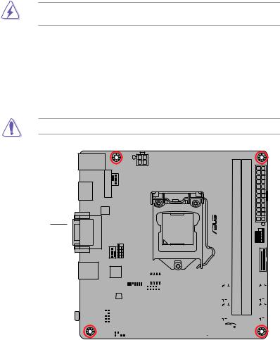
1.2Motherboard overview
Before you install the motherboard, study the configuration of your chassis to ensure that the motherboard fits.
Unplug the power cord before installing or removing the motherboard. Failure to do so can cause you physical injury and damage to motherboard components.
1.2.1Placement direction
When installing the motherboard, place it into the chassis in the correct orientation. The edge with external ports goes to the rear part of the chassis as indicated in the image.
1.2.2Screw holes
Place four screws into the holes indicated by circles to secure the motherboard to the chassis.
Do not overtighten the screws! Doing so can damage the motherboard.
Place this side towards the rear of the chassis
|
1-2 |
Chapter 1: Product introduction |
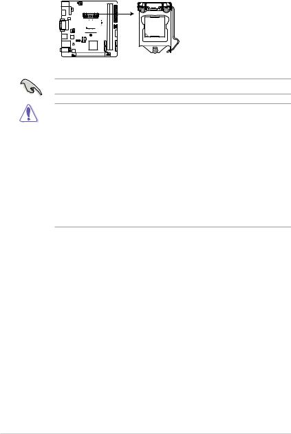
1.3Central Processing Unit (CPU)
This motherboard comes with a surface mount LGA1151 socket designed for 6th Generation Intel® Core™ i7 / i5 / i3, Pentium®, and Celeron® processors.
 H110I-PLUS D3
H110I-PLUS D3 CPU socket LGA1151
Unplug all power cables before installing the CPU.
•Ensure that you install the correct CPU designed for the LGA1151 socket only. DO NOT install a CPU designed for LGA1150, LGA1155 and LGA1156 sockets on the LGA1151 socket.
•Upon purchase of the motherboard, ensure that the PnP cap is on the socket and the socket contacts are not bent. Contact your retailer immediately if the PnP cap is missing, or if you see any damage to the PnP cap/socket contacts/motherboard components.
•Keep the cap after installing the motherboard. ASUS will process Return Merchandise Authorization (RMA) requests only if the motherboard comes with the cap on the LGA1151 socket.
•The product warranty does not cover damage to the socket contacts resulting from incorrect CPU installation/removal, or misplacement/loss/incorrect removal of the PnP cap.
|
1-4 |
Chapter 1: Product introduction |

1.3.1Installing the CPU
1
A
B
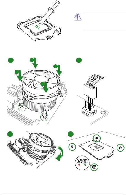
1.3.2CPU heatsink and fan assembly installation
Apply the Thermal Interface Material to the CPU heatsink and CPU before you install the heatsink and fan if necessary.
To install the CPU heatsink and fan assembly
1 A 2
B
B
A
|
1-6 |
Chapter 1: Product introduction |

To uninstall the CPU heatsink and fan assembly
A
 B B
B B 
A
1.4System memory
1.4.1Overview
This motherboard comes with two Double Data Rate 3 (DDR3) Dual Inline Memory Module (DIMM) sockets. The figure illustrates the location of the DDR3 DIMM sockets:
DIMM_B1
DIMM_A1
 H110I-PLUS D3
|
Channel |
Sockets |
|
Channel A |
DIMM_A1 |
|
Channel B |
DIMM_B1 |
H110I-PLUS D3 240-pin DDR3 DIMM sockets
![]()
1.4.2Memory configurations
You may install 2 GB, 4 GB, 8 GB, and 16 GB unbuffered non-ECC DDR3 DIMMs into the DIMM sockets. You can refer to the recommended memory population below.
Recommended memory configurations
•You may install varying memory sizes in Channel A and Channel B. The system maps
the total size of the lower-sized channel for the dual-channel configuration. Any excess memory from the higher-sized channel is then mapped for single-channel operation.
•Due to the memory address limitation on 32-bit Windows® OS, when you install 4GB or more memory on the motherboard, the actual usable memory for the OS can be about 3GB or less. For effective use of memory, we recommend that you do any of the following:
—Use a maximum of 3 GB system memory if you are using a 32-bit Windows® OS.
—Install a 64-bit Windows® OS if you want to install 4GB or more on the motherboard.
—For more details, refer to the Microsoft® support site at http://support.microsoft. com/kb/929605/en-us.
• The default memory operation frequency is dependent on its Serial Presence Detect (SPD), which is the standard way of accessing information from a memory module. Under the default state, some memory modules for overclocking may operate at a lower frequency than the vendor-marked value. To operate at the vendor-marked or at a higher frequency, refer to section 2.5 Ai Tweaker menu for manual memory frequency adjustment.
•Always install the DIMMs with the same CAS Latency. For an optimum compatibility, we recommend that you install memory modules of the same version or data code (D/C) from the same vendor. Check with the vendor to get the correct memory modules.
Visit the ASUS website at www.asus.com for the latest QVL.
|
1-8 |
Chapter 1: Product introduction |

1.4.3Installing a DIMM
1
2
3
To remove a DIMM
B  A
A
1.5Expansion slots
In the future, you may need to install expansion cards. The following sub-sections describe the slots and the expansion cards that they support.
Unplug the power cord before adding or removing expansion cards. Failure to do so may cause you physical injury and damage motherboard components.
1.5.1Installing an expansion card
To install an expansion card:
1.Before installing the expansion card, read the documentation that came with it and make the necessary hardware settings for the card.
2.Remove the system unit cover (if your motherboard is already installed in a chassis).
3.Remove the bracket opposite the slot that you intend to use. Keep the screw for later use.
4.Align the card connector with the slot and press firmly until the card is completely seated on the slot.
5.Secure the card to the chassis with the screw you removed earlier.
6.Replace the system cover.
1.5.2Configuring an expansion card
After installing the expansion card, configure it by adjusting the software settings.
1.Turn on the system and change the necessary BIOS settings, if any. See Chapter 2 for information on BIOS setup.
2.Assign an IRQ to the card.
3.Install the software drivers for the expansion card.
When using PCI cards on shared slots, ensure that the drivers support “Share IRQ” or that the cards do not need IRQ assignments. Otherwise, conflicts will arise between the two PCI groups, making the system unstable and the card inoperable.
1.5.3PCI Express 3.0 x16 slot
This motherboard has one PCI Express 3.0 x16 slot that supports PCI Express 3.0 x16 graphic cards complying with the PCI Express specifications.
IRQ assignments
|
A |
B |
C |
D |
E |
F |
G |
H |
||
|
PCIEx16 |
shared |
– |
– |
– |
– |
– |
– |
– |
|
|
Realtek 8111H LAN |
– |
shared |
– |
– |
– |
– |
– |
– |
|
|
Controller |
|||||||||
|
USB 3.0 Controller |
shared |
– |
– |
– |
– |
– |
– |
– |
|
|
SATA Controller |
shared |
– |
– |
– |
– |
– |
– |
– |
|
|
HD Audio Controller |
shared |
– |
– |
– |
– |
– |
– |
– |
|
1-10 |
Chapter 1: Product introduction |

1.6Headers
Clear RTC RAM (2-pin CLRTC)
This header allows you to clear the Real Time Clock (RTC) RAM in CMOS. You can clear the CMOS memory of date, time, and system setup parameters by erasing the CMOS RTC RAM data. The onboard button cell battery powers the RAM data in CMOS, which include system setup information such as system passwords.
 H110I-PLUS D3
|
CLRTC |
|
|
BAT |
|
|
_ |
GND |
|
+3V |
|
|
PIN 1 |
H110I-PLUS D3 Clear RTC RAM
To erase the RTC RAM:
1.Turn OFF the computer and unplug the power cord.
2.Use a metal object such as a screwdriver to short the two pins.
3.Plug the power cord and turn ON the computer.
4.Hold down the <Del> key during the boot process and enter BIOS setup to reenter data.
• If the steps above do not help, remove the onboard battery and short the two pins again to clear the CMOS RTC RAM data. After clearing the CMOS, reinstall the battery.
•You do not need to clear the RTC when the system hangs due to overclocking. For system failure due to overclocking, use the CPU Parameter Recall (C.P.R.) feature. Shut down and reboot the system, then the BIOS automatically resets parameter settings to default values.
1.7Connectors
1.7.1Rear panel connectors
|
1 |
2 |
3 |
4 |
5 |
|||||||||||||||||||||||||||
|
11 |
10 |
9 |
8 |
7 |
6 |
1.PS/2 mouse/keyboard combo port. This port connects to a PS/2 mouse or PS/2 keyboard.
2.Video Graphics Adapter (VGA) port. This 15-pin port is for a VGA monitor or other VGA-compatible devices.
3.LAN (RJ-45) port. This port allows Gigabit connection to a Local Area Network (LAN) through a network hub.
LAN port LED indications
|
Activity/Link LED |
Speed LED |
||
|
Status |
Description |
Status |
Description |
|
Off |
No link |
OFF |
10Mbps connection |
|
Orange |
Linked |
ORANGE |
100Mbps connection |
|
Orange |
Data activity |
GREEN |
1Gbps connection |
|
(Blinking) |
|||
|
Orange |
Ready to |
_ |
_ |
|
(Blinking then |
wake up from |
||
|
steady) |
S5 mode |
|
Activity Link |
Speed |
||
|
LED |
LED |
||
LAN port
4.Line In port (light blue). This port connects to the tape, CD, DVD player, or other audio sources.
5.Line Out port (lime). This port connects to a headphone or a speaker. In the 4.1, 5.1 and 7.1-channel configurations, the function of this port becomes Front Speaker Out.
6.Microphone port (pink). This port connects to a microphone.
Refer to the audio configuration table for the function of the audio ports in 2.1, 4.1, 5.1, or 7.1-channel configuration.
|
1-12 |
Chapter 1: Product introduction |

Audio 2.1, 4.1, 5.1, or 7.1-channel configuration
|
Port |
Headset |
4.1-channel |
5.1-channel |
7.1-channel |
|
|
2.1-channel |
|||||
|
Light Blue (Rear panel) |
Line In |
Rear Speaker Out |
Rear Speaker Out |
Rear Speaker Out |
|
|
Lime (Rear panel) |
Line Out |
Front Speaker Out |
Front Speaker Out |
Front Speaker Out |
|
|
Pink (Rear panel) |
Mic In |
Mic In |
Bass/Center |
Bass/Center |
|
|
Lime (Front panel) |
— |
— |
— |
Side Speaker Out |
To configure a 7.1-channel audio output:
Use a chassis with HD audio module in the front panel to support a 7.1-channel audio output.
7.USB 2.0 ports. These 4-pin Universal Serial Bus (USB) ports are for USB 2.0/1.1 devices.
8.USB 3.0 ports. These 9-pin Universal Serial Bus (USB) ports are for USB 3.0 devices.
• Due to the limitation of USB 3.0 controller, USB 3.0 devices can only be used under Windows OS environment and after the USB 3.0 driver installation.
•We strongly recommend that you connect USB 3.0 devices to USB 3.0 ports for faster and better performance from your USB 3.0 devices.
9.DVI-D port. This port is for any DVI-D compatible device.
DVI-D can not be converted to output from RGB Signal to CRT and is not compatible with DVI-I.
10.HDMI port. This port is for a High-Definition Multimedia Interface (HDMI) connector, and is HDCP compliant allowing playback of HD DVD, Blu-ray, and other protected content.
11.USB 2.0 ports. These 4-pin Universal Serial Bus (USB) ports are for USB 2.0/1.1 devices.
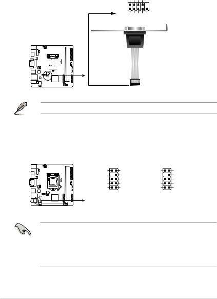
1.7.2Internal connectors
1.Serial port connector (10-1 pin COM1)
This connector is for a serial (COM) port. Connect the serial port module cable to this connector, then install the module to a slot opening at the back of the system chassis.
COM1
RXDDTRDSRCTS
PIN 1
DCDTXDGNDRTSRI
 H110I-PLUS D3
H110I-PLUS D3 Serial port (COM) connector
The COM module is purchased separately.
2.Front panel audio connector (10-1 pin AAFP)
This connector is for a chassis-mounted front panel audio I/O module that supports either HD Audio or legacy AC`97 audio standard. Connect one end of the front panel audio I/O module cable to this connector.
|
AAFP |
||||
|
SENSE2_RETUR |
PORT2 L |
NC |
Line out_L |
|
|
D3 |
SENSE_SEND |
NC |
||
|
-PLUS |
SENSE1_RETUR |
PORT2 R |
NC |
Line out_R |
|
H110I |
NC |
PORT1 R |
NC |
MICPWR |
|
AGND |
PORT1 L |
AGND |
MIC2 |
|
|
PIN 1 |
PIN 1 |
|||
|
HD-audio-compliant |
Legacy AC’97 |
|||
|
pin definition |
compliant definition |
H110I-PLUS D3 Front panel audio connector
•We recommend that you connect a high-definition front panel audio module to this connector to avail of the motherboard’s high-definition audio capability.
•If you want to connect a high-definition front panel audio module to this connector, set the Front Panel Type item in the BIOS setup to [HD Audio]. If you want to connect an AC’97 front panel audio module to this connector, set the item to [AC97]. By default, this connector is set to [HD Audio].
|
1-14 |
Chapter 1: Product introduction |
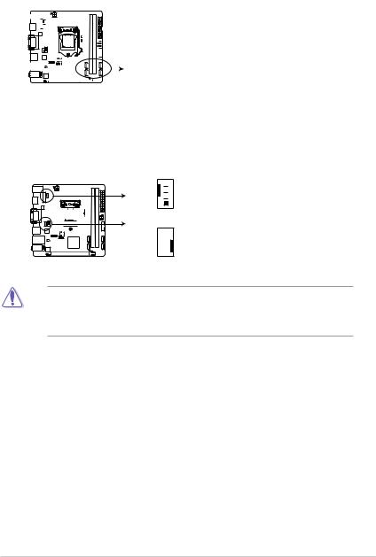
3.Intel® H110 Serial ATA 6.0Gb/s connectors (7-pin SATA6G_1~4)
These connectors connect to Serial ATA 6.0 Gb/s hard disk drives via Serial ATA 6.0 Gb/s signal cables.
|
SATA6G_1 |
SATA6G_4 |
||||||||||||||||||
|
GND |
GND |
||||||||||||||||||
|
RSATA_TXP1 |
RSATA_TXP4 |
||||||||||||||||||
|
RSATA_TXN1 |
RSATA_TXN4 |
||||||||||||||||||
|
GND |
GND |
||||||||||||||||||
|
RSATA_RXN1 |
RSATA_RXN4 |
||||||||||||||||||
|
RSATA_RXP1 |
RSATA_RXP4 |
||||||||||||||||||
|
GND |
GND |
||||||||||||||||||
|
SATA6G_2 |
SATA6G_3 |
||||||||||||||||||||||||||
|
GND |
GND |
||||||||||||||||||||||||||
|
RSATA_TXP2 |
RSATA_TXP3 |
||||||||||||||||||||||||||
|
RSATA_TXN2 |
RSATA_TXN3 |
||||||||||||||||||||||||||
|
GND |
GND |
||||||||||||||||||||||||||
|
RSATA_RXN2 |
RSATA_RXN3 |
||||||||||||||||||||||||||
|
RSATA_RXP2 |
RSATA_RXP3 |
||||||||||||||||||||||||||
|
GND |
GND |
H110I-PLUS D3 Intel® SATA 6.0Gb/s connectors
4.CPU and chassis fan connectors (4-pin CPU_FAN, 4-pin CHA_FAN)
Connect the fan cables to the fan connectors on the motherboard, ensuring that the black wire of each cable matches the ground pin of the connector
 H110I-PLUS D3
H110I-PLUS D3 Fan connectors
Do not forget to connect the fan cables to the fan connectors. Insufficient air flow inside the system may damage the motherboard components. These are not jumpers! Do not place jumper caps on the fan connectors! The CPU_FAN connector supports a CPU fan of maximum 1A (12 W) fan power.
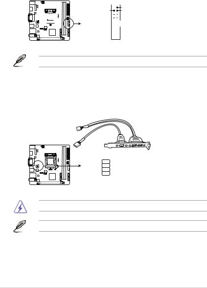
5.USB 3.0 connector (20-1 pin USB3_12)
This connector allows you to connect a USB 3.0 module for additional USB 3.0 front or rear panel ports. With an installed USB 3.0 module, you can enjoy all the benefits of USB 3.0 including faster data transfer speeds of up to 5 Gbps, faster charging time for USB-chargeable devices, optimized power efficiency, and backward compatibility with USB 2.0.
 H110I-PLUS D3
H110I-PLUS D3 USB3.0 front panel connector
The USB 3.0 module is purchased separately.
6.USB 2.0 connector (10-1 pin USB910)
This connector is for USB 2.0 ports. Connect the USB module cable to this connector, then install the module to a slot opening at the back of the system chassis. This
USB connector complies with USB 2.0 specifications and supports up to 480Mbps connection speed.
PIN 1
H110I-PLUS D3 USB2.0 connector
Never connect a 1394 cable to the USB connector. Doing so will damage the motherboard!
The USB 2.0 module is purchased separately.
|
1-16 |
Chapter 1: Product introduction |
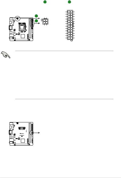
7.ATX power connectors (24-pin EATXPWR, 4-pin ATX12V)
These connectors are for ATX power supply plugs. The power supply plugs are designed to fit these connectors in only one orientation. Find the proper orientation and push down firmly until the connectors completely fit.
|
A |
B |
||||
|
ATX12V |
EATXPWR |
||||
|
DC DC |
+3 Volts |
GND |
|||
|
+12V |
+12V |
||||
|
+12 |
Volts |
+5 Volts |
|||
|
+12 |
Volts |
+5 Volts |
|||
|
+5V Standby |
+5 Volts |
||||
|
Power OK |
-5 Volts |
||||
|
PIN 1 |
GND |
GND |
|||
|
+5 Volts |
GND |
||||
|
GND GND |
|||||
|
GND |
GND |
||||
|
+5 Volts |
PSON# |
||||
|
GND |
GND |
||||
|
+3 |
Volts |
-12 Volts |
|||
|
+3 |
Volts |
+3 Volts |
H110I-PLUS D3 ATX power connectors
•For a fully configured system, we recommend that you use a power supply unit
(PSU) that complies with ATX 12 V Specification 2.0 (or later version) and provides a minimum power of 350 W.
•DO NOT forget to connect the 4-pin ATX +12V power plug. Otherwise, the system will not boot up.
•We recommend that you use a PSU with higher power output when configuring a system with more power-consuming devices or when you intend to install additional devices. The system may become unstable or may not boot up if the power is inadequate.
•If you are uncertain about the minimum power supply requirement for your system, refer to the Recommended Power Supply Wattage Calculator at http://support.asus. com/PowerSupplyCalculator/PSCalculator.aspx?SLanguage=en-us for details.
8.Speaker connector (4-pin SPEAKER)
The 4-pin connector is for the chassis-mounted system warning speaker. The speaker allows you to hear system beeps and warnings.
 H110I-PLUS D3
H110I-PLUS D3 Speaker out connector
![]()
9.System panel connector (10-1 pin F_PANEL)
This connector supports several chassis-mounted functions.
F_PANEL
H110I-PLUS D3 System panel connector
•System power LED (2-pin +PWR_LED-)
This 2-pin connector is for the system power LED. Connect the chassis power LED cable to this connector. The system power LED lights up when you turn on the system power, and blinks when the system is in sleep mode.
•Hard disk drive activity LED (2-pin +HDD_LED-)
This 2-pin connector is for the HDD Activity LED. Connect the HDD Activity LED cable to this connector. The HD LED lights up or flashes when data is read from or written to the HDD.
•ATX power button/soft-off button (2-pin PWRBTN)
This connector is for the system power button.
•Reset button (2-pin RESET)
This 2-pin connector is for the chassis-mounted reset button for system reboot without turning off the system power.
10.TPM connector (14-1 pin TPM)
This connector supports a Trusted Platform Module (TPM) system, which can securely store keys, digital certificates, passwords, and data. A TPM system also helps enhance network security, protects digital identities, and ensures platform integrity.
TPM
CLKRUN_F SERIRQ_F FRAME#_F LAD3_F LAD2_F LAD1_F LAD0_F
PIN 1
 H110I-PLUS D3
|
+3VSB S PCIRST# TBD |
GND C PCICLK TPM +3V +3V |
H110I-PLUS D3 TPM connector
The TPM module is purchased separately.
|
1-18 |
Chapter 1: Product introduction |