- Manuals
- Brands
- ASROCK Manuals
- Motherboard
- 760GM-HDV
- User manual
-
Contents
-
Table of Contents
-
Bookmarks
Quick Links
Related Manuals for ASROCK 760GM-HDV
Summary of Contents for ASROCK 760GM-HDV
-
Page 2: Copyright Notice
(including damages for loss of profits, loss of business, loss of data, interruption of business and the like), even if ASRock has been advised of the possibility of such damages arising from any defect or error in the documentation or product.
-
Page 3
If you require assistance please call ASRock Tel : +886-2-28965588 ext.123 (Standard International call charges apply) The terms HDMI™… -
Page 4: Table Of Contents
Expansion Slots (PCI and PCI Express Slots) Jumpers Setup Onboard Headers and Connectors Chapter 3 Software and Utilities Operation Installing Drivers ASRock Live Update & APP Shop 3.2.1 UI Overview 3.2.2 Apps 3.2.3 BIOS & Drivers 3.2.4 Setting Chapter 4 BIOS SETUP UTILITY Introduction 4.1.1…
-
Page 5
4.1.2 Navigation Keys Main Screen OC Tweaker Screen Advanced Screen 4.4.1 CPU Configuration 4.4.2 Chipset Configuration 4.4.3 ACPI Configuration 4.4.4 Storage Configuration 4.4.5 PCIPnP Configuration 4.4.6 USB Configuration Hardware Health Event Monitoring Screen Boot Screen 4.6.1 Boot Settings Configuration. Security Screen Exit Screen… -
Page 6: Chapter 1 Introduction
If you require technical support related to this motherboard, please visit our website for specific information about the model you are using. You may find the latest VGA cards and CPU support list on ASRock’s website as well. ASRock website http://www.asrock.com.
-
Page 7: Specifications
1.2 Specifications Platform • Micro ATX Form Factor • Solid Capacitor design • Supports Socket AM3+ processors • Supports Socket AM3 processors: AMD Phenom II X6 / X4 / X3 / X2 (except 920 / 940) / Athlon II X4 / X3 / X2 / Sempron processors • Supports 8-Core CPU • Supports AMD OverDrive…
-
Page 8
760GM-HDV • Supports DVI-D with max. resolution up to 1920×1200 @ 75Hz • Supports D-Sub with max. resolution up to 2048×1536 @ 60Hz • Supports HDCP with DVI-D and HDMI Ports • Supports Full HD 1080p Blu-ray (BD) / HD-DVD playback… -
Page 9
• ErP/EuP ready (ErP/EuP ready power supply is required) * For detailed product information, please visit our website: http://www.asrock.com Please realize that there is a certain risk involved with overclocking, including adjusting the setting in the BIOS, applying Untied Overclocking Technology, or using third-party overclocking tools. -
Page 10
CPU you adopt. If you want to adopt DDR3 1800/1600 memory module on this motherboard, please refer to the memory support list on our website for the compatible memory modules. ASRock website: http://www.asrock.com 2. Due to the operating system limitation, the actual memory size may be less than 4GB for the reservation for system usage under Windows®… -
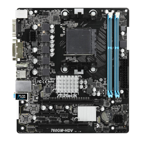
Page 11: Motherboard Layout
CPU_FAN1 ATX12V1 HDMI2 USB 2.0 T: USB2 B: USB3 RoHS 760G USB 2.0 Top: T: USB0 RJ-45 Chipset B: USB1 PCIE1 CHA_FAN2 SB710 PCIE2 CMOS BATTERY Chipset USB6_7 USB4_5 PANEL 1 CLRMOS1 PCI1 HD_AUDIO2 SATAII_1 (PORT 1) SPK_CI1 760GM-HDV CHA_FAN1…
-
Page 12
760GM-HDV No. Description ATX 12V Power Connector (ATX12V1) CPU Fan Connector (CPU_FAN1) CPU Socket CPU Heatsink Retention Module 2 x 240-pin DDR3 DIMM Slots (DDR3_A1, DDR3_B1) ATX Power Connector (ATXPWR1) SATA2 Connector (SATAII_4 (PORT4)) Chassis Fan Connector (CHA_FAN2) System Panel Header (PANEL1) -
Page 13: I/O Panel
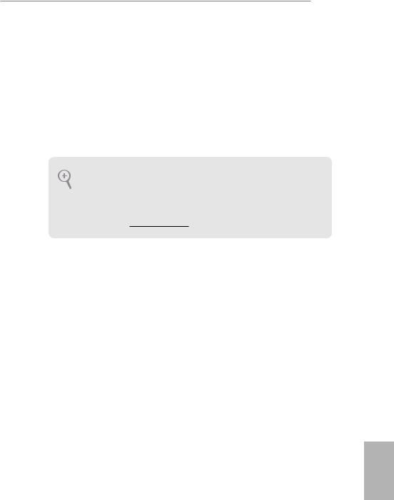
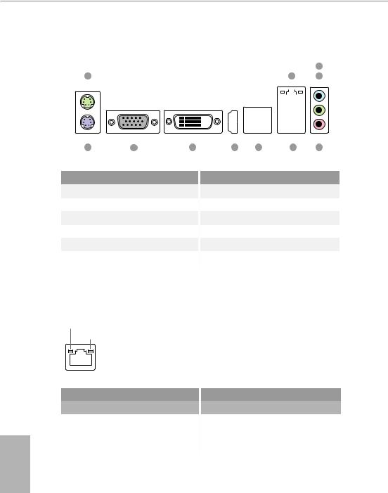
1.4 I/O Panel No. Description No. Description PS/2 Mouse Port USB 2.0 Ports (USB23) LAN RJ-45 Port* HDMI Port Line In (Light Blue)** DVI-D Port Front Speaker (Lime)** D-Sub Port Microphone (Pink)** PS/2 Keyboard Port USB 2.0 Ports (USB01) * There are two LEDs on the LAN port. Please refer to the table below for the LAN port LED indications. ACT/LINK LED SPEED LED LAN Port…
-
Page 14
760GM-HDV ** To configure 7.1 CH HD Audio, it is required to use an HD front panel audio module and enable the multi- channel audio feature through the audio driver. Please set Speaker Configuration to “7.1 Speaker”in the Realtek HD Audio Manager. -
Page 15: Chapter 2 Installation
Chapter 2 Installation This is a Micro ATX form factor motherboard. Before you install the motherboard, study the configuration of your chassis to ensure that the motherboard fits into it. Pre-installation Precautions Take note of the following precautions before you install motherboard components or change any motherboard settings.
-
Page 16: Installing The Cpu
760GM-HDV 2.1 Installing the CPU Unplug all power cables before installing the CPU.
-
Page 18: Installing The Cpu Fan And Heatsink
760GM-HDV 2.2 Installing the CPU Fan and Heatsink After you install the CPU into this motherboard, it is necessary to install a larger heatsink and cooling fan to dissipate heat. You also need to spray thermal grease between the CPU and the heatsink to improve heat dissipation. Make sure that the CPU and the heatsink are securely fastened and in good contact with each other.
-
Page 19: Installing Memory Modules (Dimm)
2.3 Installing Memory Modules (DIMM) This motherboard provides two 240-pin DDR3 (Double Data Rate 3) DIMM slots, and supports Dual Channel Memory Technology. 1. For dual channel configuration, you always need to install identical (the same brand, speed, size and chip-type) DDR3 DIMM pairs. 2.
-
Page 20
760GM-HDV… -
Page 21: Expansion Slots (Pci And Pci Express Slots)
2.4 Expansion Slots (PCI and PCI Express Slots) There is 1 PCI slot and 2 PCI Express slots on the motherboard. Before installing an expansion card, please make sure that the power supply is switched off or the power cord is unplugged. Please read the documentation of the expansion card and make necessary hardware settings for the card before you start the installation.
-
Page 22: Jumpers Setup
760GM-HDV 2.5 Jumpers Setup The illustration shows how jumpers are setup. When the jumper cap is placed on the pins, the jumper is “Short”. If no jumper cap is placed on the pins, the jumper is “Open”. Clear CMOS Jumper…
-
Page 23: Onboard Headers And Connectors
2.6 Onboard Headers and Connectors Onboard headers and connectors are NOT jumpers. Do NOT place jumper caps over these headers and connectors. Placing jumper caps over the headers and connectors will cause permanent damage to the motherboard. System Panel Header Connect the power (9-pin PANEL1) switch, reset switch and…
-
Page 24
760GM-HDV Chassis Intrusion and Please connect the SPEAKER DUMMY Speaker Header chassis intrusion and the DUMMY (7-pin SPK_CI1) chassis speaker to this (see p.6, No. 15) header. SIGNAL DUMMY Serial ATA2 Connectors These four SATA2 (SATAII_1 (PORT1): connectors support SATA see p.6, No. -
Page 25: Pin Atxpwr
1. High Definition Audio supports Jack Sensing, but the panel wire on the chassis must support HDA to function correctly. Please follow the instructions in our manual and chassis manual to install your system. 2. If you use an AC’97 audio panel, please install it to the front panel audio header by the steps below: A.
-
Page 26
760GM-HDV ATX 12V Power This motherboard pro- Connector vides an 8-pin ATX 12V (8-pin ATX12V1) power connector. To use a (see p.6, No. 1) 4-pin ATX power supply, please plug it along Pin 1 and Pin 5. -
Page 27: Chapter 3 Software And Utilities Operation
Chapter 3 Software and Utilities Operation 3.1 Installing Drivers The Support CD that comes with the motherboard contains necessary drivers and useful utilities that enhance the motherboard’s features. Running The Support CD To begin using the support CD, insert the CD into your CD-ROM drive. The CD automatically displays the Main Menu if “AUTORUN”…
-
Page 28: Asrock Live Update & App Shop
Double-click on your desktop to access ASRock Live Update & APP Shop utility. *You need to be connected to the Internet to download apps from the ASRock Live Update & APP Shop. 3.2.1 UI Overview Category Panel Hot News…
-
Page 29: Apps
3.2.2 Apps When the «Apps» tab is selected, you will see all the available apps on screen for you to download. Installing an App Step 1 Find the app you want to install. The most recommended app appears on the left side of the screen. The other various apps are shown on the right.
-
Page 30
760GM-HDV Step 3 If you want to install the app, click on the red icon to start downloading. Step 4 When installation completes, you can find the green «Installed» icon appears on the upper right corner. To uninstall it, simply click on the trash can icon… -
Page 31
Upgrading an App You can only upgrade the apps you have already installed. When there is an available new version for your app, you will find the mark of «New Version» appears below the installed app icon. Step 1 Click on the app icon to see more details. Step 2 Click on the yellow icon to start upgrading. -
Page 32: Bios & Drivers
760GM-HDV 3.2.3 BIOS & Drivers Installing BIOS or Drivers When the «BIOS & Drivers» tab is selected, you will see a list of recommended or critical updates for the BIOS or drivers. Please update them all soon. Step 1 Please check the item information before update. Click on to see more details.
-
Page 33: Setting
3.2.4 Setting In the «Setting» page, you can change the language, select the server location, and determine if you want to automatically run the ASRock Live Update & APP Shop on Windows startup.
-
Page 34: Chapter 4 Bios Setup Utility
760GM-HDV Chapter 4 BIOS SETUP UTILITY 4.1 Introduction This section explains how to use the BIOS SETUP UTILITY to configure your system. You may run the BIOS SETUP UTILITY by pressing <F2> or <Del> right after you power on the computer, otherwise, the Power-On-Self-Test (POST) will continue with its test routines.
-
Page 35: Navigation Keys
4.1.2 Navigation Keys Use < > key or < > key to choose among the selections on the menu bar, and use < > key or < > key to move the cursor up or down to select items, then press <Enter>…
-
Page 36: Main Screen
Use [Enter], [TAB] System Time [ :00:09] or [SHIFT-TAB] to System Date [Wed 11/14/2012] select a field. BIOS Version : 760GM-HDV P1.00 Use [+] or [-] to : AMD FX(tm)-8100 Eight-Core Processor Type configure system Time. Processor (64bit) Processor Speed…
-
Page 37: Oc Tweaker Screen
4.3 OC Tweaker Screen In the OC Tweaker screen, you can set up overclocking features. BIOS SETUP UTILITY Main OC Tweaker Advanced H/W Monitor Boot Security Exit CPU Configuration Overclocking may cause damage to your CPU and motherboard. Overclock Mode [Auto] It should be done at CPU Frequency (MHz)
-
Page 38
760GM-HDV Boot Failure Guard Count Configure the number of attempts to boot until the system automatically restores the default settings. CPU Active Core Control This allows you to adjust CPU Active Core Control feature. The configuration options depend on the CPU core you adopt. The default value is [Disabled]. -
Page 39: Cpu Voltage
BIOS SETUP UTILITY Main OC Tweaker Advanced H/W Monitor Boot Security Exit CPU Configuration Overclocking may cause damage to your CPU and motherboard. Overclock Mode [Auto] It should be done at CPU Frequency (MHz) [200] your own risk and PCIE Frequency (MHz) [100] expense.
-
Page 40: Memory Timing
760GM-HDV Memory Timing BIOS SETUP UTILITY OC Tweaker Memory Timing [Enabled] Power Down Enable Bank Interleaving [Auto] Channel Interleaving [Auto] CAS Latency (CL) [Auto] TRCD [Auto] [Auto] TRAS [Auto] [Auto] Command Rate [Auto] Select Screen Select Screen [Auto] Select Item…
-
Page 41: Chipset Settings
Use this item to change Command Rate Auto/Manual setting. The default is [Auto]. Use this item to change TRC Auto/Manual setting. The default is [Auto]. Use this item to change TWR Auto/Manual setting. The default is [Auto]. TRFC Use this item to change TRFC Auto/Manual setting. The default is [Auto]. TRRD Use this item to change TRRD Auto/Manual setting.
-
Page 42
760GM-HDV Use this to configure +2.5V Voltage. The default value is [Auto]. VCORE Offset Voltage Use this to configure Vcore offset Voltage. The default value is [Auto]. VCORE Droop Voltage Use this to configure Vcore droop Voltage. The default value is [Auto]. -
Page 43: Advanced Screen
4.4 Advanced Screen In this section, you may set the configurations for the following items: CPU Configuration, Chipset Configuration, ACPI Configuratio, Storage Configuration, PCIPnP Configuration and USB Configuration. BIOS SETUP UTILITY Main OC Tweaker H/W Monitor Boot Security Exit Advanced Advanced Settings Options for CPU WARNING : Setting wrong values in below sections…
-
Page 44: Cpu Configuration
760GM-HDV 4.4.1 CPU Configuration BIOS SETUP UTILITY Advanced CPU Configuration Cool’ n’ Quiet [Enabled] [Enabled] Secure Virtual Machine Enhanced Halt State(C1E) [Disabled] CPU Thermal Throttle [Auto] Select Screen Select Screen Select Item Select Item Change Option Change Option General Help…
-
Page 45: Chipset Configuration
4.4.2 Chipset Configuration BIOS SETUP UTILITY Advanced Chipset Settings Onboard HD Audio [Auto] Front Panel [Auto] Onboard Lan [Enabled] Internal Graphics Mode [UMA] Share Memory [Auto] Onboard HDMI HD Audio [Enabled] Surround View [Auto] Select Screen Select Item Change Option General Help Load Defaults Save and Exit…
-
Page 46: Acpi Configuration
760GM-HDV 4.4.3 ACPI Configuration BIOS SETUP UTILITY Advanced ACPI Settings Select auto-detect or disable the STR feature. Suspend To RAM [Auto] Check Ready Bit [Auto] Away Mode Support [Disabled] Restore on AC / Power Loss [Power Off] PCI Devices Power On…
-
Page 47: Deep Sleep
Allow the system to be waked up by the real time clock alarm. Set it to By OS to let it be handled by your operating system. ACPI HPET table Use this item to enable or disable ACPI HPET Table. The default value is [Enabled]. Please set this option to [Enabled] if you plan to use this motherboard to submit Windows®…
-
Page 48: Storage Configuration
760GM-HDV 4.4.4 Storage Configuration BIOS SETUP UTILITY Advanced Configure onboard Storage Configuration serial ATA controller. Onboard SATA Controller [Enabled] SATA Operation Mode [AHCI] [Enabled] SATA IDE Combined Mode [Hard Disk] SATAII_1 SATAII_2 [Not Detected] SATAII_3 [Not Detected] SATAII_4 [Not Detected]…
-
Page 49: Pcipnp Configuration
4.4.5 PCIPnP Configuration BIOS SETUP UTILITY Advanced Value in units of PCI Advanced PCI / PnP Settings clocks for PCI device latency timer PCI Latency Timer [32] register. [Enabled] PCI IDE BusMaster Select Screen Select Item Change Option General Help Load Defaults Save and Exit Exit…
-
Page 50: Usb Configuration
760GM-HDV 4.4.6 USB Configuration BIOS SETUP UTILITY Advanced USB Configuration To enable or disable the onboard USB controllers. [Enabled] USB Controller USB 2.0 Support [Enabled] Legacy USB Support [Enabled] USB Keyboard/Remote Power On [Disabled] USB Mouse Power On [Disabled] Select Screen…
-
Page 51: Hardware Health Event Monitoring Screen
4.5 Hardware Health Event Monitoring Screen This section allows you to monitor the status of the hardware on your system, including the parameters of the CPU temperature, motherboard temperature, fan speed and voltage. BIOS SETUP UTILITY Main OC Tweaker Advanced H/W Monitor Boot Security…
-
Page 52: Boot Screen
760GM-HDV 4.6 Boot Screen This section displays the available devices on your system for you to configure the boot settings and the boot priority. BIOS SETUP UTILITY Main OC Tweaker Advanced H/W Monitor Boot Security Exit Boot Settings Configure Settings during System Boot.
-
Page 53: Boot Settings Configuration
4.6.1 Boot Screen BIOS SETUP UTILITY Boot Boot Settings Configuration Disabled: Displays normal POST messages. Full Screen Logo [Enabled] Enabled: Displays OEM AddOn ROM Display [Enabled] Logo instead of POST Boot From Onboard LAN [Disabled] messages. Bootup Num-Lock [ON] Select Screen Select Item Change Option General Help…
-
Page 54: Security Screen
760GM-HDV 4.7 Security Screen In this section you may set or change the supervisor/user password for the system. You may also clear the user password. BIOS SETUP UTILITY Security Exit Main OC Tweaker Advanced H/W Monitor Boot Security Settings Install or Change the password.
-
Page 55: Exit Screen
4.8 Exit Screen BIOS SETUP UTILITY Main OC Tweaker Advanced H/W Monitor Boot Security Exit Exit Options Exit system setup after saving the Save Changes and Exit changes. Discard Changes and Exit Discard Changes F10 key can be used for this operation. Load BIOS Defaults Load Performance Setup Default Load Power Saving Setup Default…
-
Page 56: Contact Information
Contact Information If you need to contact ASRock or want to know more about ASRock, you’re welcome to visit ASRock’s website at http://www.asrock.com; or you may contact your dealer for further information. For technical questions, please submit a support request form at https://event.asrock.com/tsd.asp…
-
Page 57: Declaration Of Conformity
DECLARATION OF CONFORMITY Per FCC Part 2 Section 2.1077(a) Responsible Party Name: ASRock Incorporation Address: 13848 Magnolia Ave, Chino, CA91710 Phone/Fax No: +1-909-590-8308/+1-909-590-1026 hereby declares that the product Product Name : Motherboard 760GM-HDV Model Number : Conforms to the following speci cations:…
-
Page 58
EU Declaration of Conformity For the following equipment: Motherboard (Product Name) 760GM-HDV / ASRock (Model Designation / Trade Name) ASRock Incorporation (Manufacturer Name) 2F., No.37, Sec. 2, Jhongyang S. Rd., Beitou District, Taipei City 112, Taiwan (R.O.C.) (Manufacturer Address) EMC —Directive 2014/30/EU (from April 20th, 2016)
Материнская плата ASRock 760GM-HDV

AM3+, AMD 760G, 2xDDR3-1333 МГц, 1xPCI-Ex16, Micro-ATX
подробнее

78496,92
Код товара: 1257394
(Ocr-Read Summary of Contents of some pages of the ASROCK 760GM-HDV Document (Main Content), UPD: 05 June 2023)
-
23, 18 English 2.6 Onboard Headers and Connectors System Panel Header (9-pin PANEL1) (see p.6, No. 9) Connect the power switch, reset switch and system status indicator on the chassis to this header according to the pin assignments below. Note the positive and negative pins before connecting the cables. PWRBTN (Power Switch): Connect to the power switch on the chassis front panel. You may congure the w…
-
58, ASROCK 760GM-HDV EU Declaration of Conformity For the following equipment: Motherboard (Product Name) 760GM-HDV / ASRock (Model Designation / Trade Name) ASRock Incorporation (Manufacturer Name) 2F., No.37, Sec. 2, Jhongyang S. Rd., Beitou District, Taipei City 112, Taiwan (R.O.C.) (Manufacturer Address) ASRock EUROPE B.V. (Company Name) Bijsterhuizen 1111 6546 AR Nijmegen e Netherlands (Company Address) Person respon…
-
10, 5 English 760GM-HDV 1. Whether 1800/1600MHz memory speed is supported depends on the AM3/AM3+ CPU you adopt. If you want to adopt DDR3 1800/1600 memory module on this motherboard, please refer to the memory support list on our website for the compatible memory modules. ASRock website: http://www.asrock.com 2. Due to the operating system limitation, the actual memory size may be less than 4GB for the reservation for system usage und…
-
5, 4.1.2 Navigation Keys 30 4.2 Main Screen 31 4.3 OC Tweaker Screen 32 4.4 Advanced Screen 38 4.4.1 CPU Conguration 39 4.4.2 Chipset Conguration 40 4.4.3 ACPI Conguration 41 4.4.4 Storage Conguration 43 4.4.5 PCIPnP Conguration 44 4.4.6 USB Conguration 45 4.5 Hardware Health Event Monitoring Screen 46 4.6 Boot Screen 47 4.6.1 Boot Settings Conguration. 48 4.7 Security Screen 49 …
-
25, 20 English Chassis Fan Connectors (4-pin CHA_FAN1) (see p.6, No. 14) (3-pin CHA_FAN2) (see p.6, No.
 Please connect fan cables to the fan connectors and match the black wire to the ground pin. CPU Fan Connector (4-pin CPU_FAN1) (see p.6, No. 2) is motherboard pro- vides a 4-Pin CPU fan (Quiet Fan) connector. If you plan to connect a 3-Pin CPU fan, please connect it to Pin 1-3. ATX Power Connector (24-pin ATXPWR1) (see p.6, No. 6) is motherboard pro- vides a 24-pin ATX power co…
 -
26, 21 English 760GM-HDV ATX 12V Power Connector (8-pin ATX12V1) (see p.6, No. 1) is motherboard pro- vides an 8-pin ATX 12V power connector. To use a 4-pin ATX power supply, please plug it along Pin 1 and Pin 5. 5 8 1 4
… -
39, 34 English CPU Frequency Multiplier For safety and system stability, it is not recommended to adjust the value of this item. CPU Voltage It allows you to adjust the value of CPU voltage. However, for safety and system stability, it is not recommended to adjust the value of this item. NB Frequency Multiplier For safety and system stability, it is not recommended to adjust the value of this item. HT Bus Speed is feature allows you selecting…
-
51, 46 English 4.5 Hardware Health Event Monitoring Screen is section allows you to monitor the status of the hardware on your system, including the parameters of the CPU temperature, motherboard temperature, fan speed and voltage. CPU Fan Setting is allows you to set the CPU fan speed. Conguration options: [Full On] and [Automatic Mode]. e default is value [Full On]. Chassis Fan 1 Setting is allows you to set …
-
29, ASROCK 760GM-HDV 24 English 3.2.2 Apps When the «Apps» tab is selected, you will see all the available apps on screen for you to download. Installing an App Step 1 Find the app you want to install. e most recommended app appears on the le side of the screen. e other various apps are shown on the right. Please scroll up and down to see more apps listed. You can check the price of the app and whether you have already intalled it or not. — e red icon displays the price or &…
-
42, 37 English 760GM-HDV Use this to congure +2.5V Voltage. e default value is [Auto]. VCORE Oset Voltage Use this to congure Vcore oset Voltage. e default value is [Auto]. VCORE Droop Voltage Use this to congure Vcore droop Voltage. e default value is [Auto]. Would you like to save current setting user defaults? In this option, you are allowed to load and save three user defaults according to yo…
-
6, 1 English 760GM-HDV Chapter 1 Introduction ank you for purchasing ASRock 760GM-HDV motherboard, a reliable motherboard produced under ASRock’s consistently stringent quality control. It delivers excellent performance with robust design conforming to ASRock’s commitment to quality and endurance. In this manual, Chapter 1 and 2 contains the introduction of the motherboard and step-by-step installation guides. Chapter 3 contains the operation guide of the…
-
56, Contact Information If you need to contact ASRock or want to know more about ASRock, you’re welcome to visit ASRock’s website at http://www.asrock.com; or you may contact your dealer for further information. For technical questions, please submit a support request form at https://event.asrock.com/tsd.asp ASRock Incorporation 2F., No.37, Sec. 2, Jhongyang S. Rd., Beitou District, Taipei City 112, Taiwan (R.O.C.) ASRock EUROPE B.V.…
-
4, ASROCK 760GM-HDV Contents Chapter 1 Introduction 1 1.1 Package Contents 1 1.2 Specications 2 1.3 Motherboard Layout 6 1.4 I/O Panel 8 Chapter 2 Installation 10 2.1 Installing the CPU 11 2.2 Installing the CPU Fan and Heatsink 13 2.3 Installing Memory Modules (DIMM) 14 2.4 Expansion Slots (PCI and PCI Express Slots) 16 2.5 Jumpers Setup 17 2.6 Onboard Headers and Connectors 18 Chapte…
-
11, 6 English 1.3 Motherboard Layout CMOS BATTERY AMD 760G Chipset PCI1 1 CLR MO S1 CPU_ FAN 1 HDL ED RESE T PLE D PWR BT N 1 PANE L 1 HD_AUDIO2 1 RoHS AMD SB710 Chipset SATAI I_ 4 (P OR T 4) USB6 _7 1 PCIE1 Top: LINE IN Cente r: FRONT Botto m: MIC IN PS2 Mouse PS2 Keyboa rd USB 2.0 T: USB0 B: USB1 Top: RJ-45 USB 2.0 T: U SB2 B: USB3 FSB800 DDR3_A1 (64 bit, 240-pin module) DDR3_B1 (64 bit, 240-pin module) 760GM-HDV SOCKET AM3b SATAI I_ 3 (P OR T 3) SATAI I_ 2 (P OR T 2) SATAI I_ 1 (P OR T …
-
55, 50 English 4.8 Exit Screen Save Changes and Exit When you select this option the following message, “Save conguration changes and exit setup?” will pop out. Select [OK] to save changes and exit the BIOS SETUP UTILITY. Discard Changes and Exit When you select this option the following message, “Discard changes and exit setup?” will pop out. Select [OK] to exit the BIOS SETUP UTILITY without saving any changes. Discard Cha…
 Please connect fan cables to the fan connectors and match the black wire to the ground pin. CPU Fan Connector (4-pin CPU_FAN1) (see p.6, No. 2) is motherboard pro- vides a 4-Pin CPU fan (Quiet Fan) connector. If you plan to connect a 3-Pin CPU fan, please connect it to Pin 1-3. ATX Power Connector (24-pin ATXPWR1) (see p.6, No. 6) is motherboard pro- vides a 24-pin ATX power co…
Version 1.0
Published April 2018
Copyright©2018 ASRock INC. All rights reserved.
Copyright Notice:
No part of this documentation may be reproduced, transcribed, transmitted, or translated in any language, in any form or by any means, except duplication of documentation by the purchaser for backup purpose, without written consent of ASRock Inc.
Products and corporate names appearing in this documentation may or may not be registered trademarks or copyrights of their respective companies, and are used only for identification or explanation and to the owners’ benefit, without intent to
infringe.
Disclaimer:
Specifications and information contained in this documentation are furnished for informational use only and subject to change without notice, and should not be constructed as a commitment by ASRock. ASRock assumes no responsibility for any errors or omissions that may appear in this documentation.
With respect to the contents of this documentation, ASRock does not provide warranty of any kind, either expressed or implied, including but not limited to the implied warranties or conditions of merchantability or fitness for a particular purpose.
In no event shall ASRock, its directors, officers, employees, or agents be liable for any indirect, special, incidental, or consequential damages (including damages for loss of profits, loss of business, loss of data, interruption of business and the like), even if ASRock has been advised of the possibility of such damages arising from any defect or error in the documentation or product.
This device complies with Part 15 of the FCC Rules. Operation is subject to the following two conditions:
(1)this device may not cause harmful interference, and
(2)this device must accept any interference received, including interference that may cause undesired operation.
CALIFORNIA, USA ONLY
The Lithium battery adopted on this motherboard contains Perchlorate, a toxic substance controlled in Perchlorate Best Management Practices (BMP) regulations passed by the California Legislature. When you discard the Lithium battery in California, USA, please follow the related regulations in advance.
“Perchlorate Material-special handling may apply, see www.dtsc.ca.gov/hazardouswaste/ perchlorate”
ASRock Website: http://www.asrock.com

AUSTRALIA ONLY
Our goods come with guarantees that cannot be excluded under the Australian Consumer Law. You are entitled to a replacement or refund for a major failure and compensation for any other reasonably foreseeable loss or damage caused by our goods. You are also entitled to have the goods repaired or replaced if the goods fail to be of acceptable quality and the failure does not amount to a major failure. If you require assistance please call ASRock Tel : +886-2-28965588 ext.123 (Standard International call charges apply)
The terms HDMI™ and HDMI High-Definition Multimedia Interface, and the HDMI logo are trademarks or registered trademarks of HDMI Licensing LLC in the United States and other countries.
Contents
|
Chapter 1 Introduction |
1 |
|
|
1.1 |
Package Contents |
1 |
|
1.2 |
Specifications |
2 |
|
1.3 |
Motherboard Layout |
6 |
|
1.4 |
I/O Panel |
8 |
|
Chapter 2 Installation |
10 |
|
|
2.1 |
Installing the CPU |
11 |
|
2.2 |
Installing the CPU Fan and Heatsink |
13 |
|
2.3 |
Installing Memory Modules (DIMM) |
14 |
|
2.4 |
Expansion Slots (PCI and PCI Express Slots) |
16 |
|
2.5 |
Jumpers Setup |
17 |
|
2.6 |
Onboard Headers and Connectors |
18 |
|
Chapter 3 Software and Utilities Operation |
22 |
|
|
3.1 |
Installing Drivers |
22 |
|
3.2 |
ASRock Live Update & APP Shop |
23 |
|
3.2.1 |
UI Overview |
23 |
|
3.2.2 |
Apps |
24 |
|
3.2.3 |
BIOS & Drivers |
27 |
|
3.2.4 |
Setting |
28 |
|
Chapter 4 BIOS SETUP UTILITY |
29 |
|
|
4.1 |
Introduction |
29 |
|
4.1.1 |
BIOS Menu Bar |
29 |
|
4.1.2 |
Navigation Keys |
30 |
|
4.2 |
Main Screen |
31 |
|
4.3 |
OC Tweaker Screen |
32 |
|
4.4 |
Advanced Screen |
38 |
|
4.4.1 |
CPU Configuration |
39 |
|
4.4.2 |
Chipset Configuration |
40 |
|
4.4.3 |
ACPI Configuration |
41 |
|
4.4.4 |
Storage Configuration |
43 |
|
4.4.5 |
PCIPnP Configuration |
44 |
|
4.4.6 |
USB Configuration |
45 |
|
4.5 |
Hardware Health Event Monitoring Screen |
46 |
|
4.6 |
Boot Screen |
47 |
|
4.6.1 |
Boot Settings Configuration. |
48 |
|
4.7 |
Security Screen |
49 |
|
4.8 |
Exit Screen |
50 |
760GM-HDV
Chapter 1 Introduction
Thank you for purchasing ASRock 760GM-HDV motherboard, a reliable motherboard produced under ASRock’s consistently stringent quality control. It delivers excellent performance with robust design conforming to ASRock’s commitment to quality and endurance.
In this manual, Chapter 1 and 2 contains the introduction of the motherboard and step-by-step installation guides. Chapter 3 contains the operation guide of the
software and utilities. Chapter 4 contains the configuration guide of the BIOS setup.
Because the motherboard specifications and the BIOS software might be updated, the content of this manual will be subject to change without notice. In case any modifications of this manual occur, the updated version will be available on ASRock’s website without further notice. If you require technical support related to this motherboard, please visit our website for specific information about the model you are using. You may find the latest VGA cards and CPU support list on ASRock’s website as well. ASRock website http://www.asrock.com.
1.1 Package Contents
•ASRock 760GM-HDV Motherboard (Micro ATX Form Factor)
•ASRock 760GM-HDV Quick Installation Guide
•ASRock 760GM-HDV Support CD
•2 x Serial ATA (SATA) Data Cables (Optional)
•1 x I/O Panel Shield
English
1

English
1.2 Specifications
|
Platform |
• |
Micro ATX Form Factor |
|
• |
Solid Capacitor design |
|
|
CPU |
• |
Supports Socket AM3+ processors |
|
• Supports Socket AM3 processors: AMD PhenomTM II X6 |
||
|
/ X4 / X3 / X2 (except 920 / 940) / Athlon II X4 / X3 / X2 / |
||
|
Sempron processors |
||
|
• Supports 8-Core CPU |
||
|
• Supports AMD OverDriveTM with ACC feature (Advanced |
||
|
Clock Calibration) |
||
|
• 4 + 1 Power Phase design |
||
|
• Supports CPU up to 125W |
||
|
• AMD LIVE!TM Ready |
||
|
• Supports AMD’s Cool ‘n’ Quiet Technology |
||
|
• FSB 2600 MHz (5.2 GT/s) |
||
|
• Supports Untied Overclocking Technology |
||
|
• Supports Hyper-Transport 3.0 (HT 3.0) Technology |
||
|
Chipset |
• |
Northbridge: AMD 760G |
|
• |
Southbridge: AMD SB710 |
|
|
Memory |
• |
Dual Channel DDR3 Memory Technology |
|
• 2 x DDR3 DIMM Slots |
||
|
• Supports DDR3 1800(OC)/1600(OC)/1333/1066 non-ECC, |
||
|
un-buffered memory |
||
|
• Max. capacity of system memory: 32GB |
||
|
Expansion |
• |
1 x PCI Express 2.0 x16 Slot (PCIE1: x16 mode) |
|
Slot |
• |
1 x PCI Express 2.0 x1 Slot |
|
• 1 x PCI Slot |
Graphics • Integrated AMD Radeon 3000 Graphics
•DX10 class iGPU, Pixel Shader 4.0
•Max. shared memory 1024MB
•Three graphics output options: D-Sub, DVI-D and HDMI
*DVI-D and HDMI cannot work simultaneously
•Supports HDMI with max. resolution up to 1920×1200 @ 75Hz
2

760GM-HDV
• Supports DVI-D with max. resolution up to 1920×1200 @ 75Hz
• Supports D-Sub with max. resolution up to 2048×1536 @
|
60Hz |
||
|
• Supports HDCP with DVI-D and HDMI Ports |
||
|
• Supports Full HD 1080p Blu-ray (BD) / HD-DVD playback |
||
|
with DVI-D Port |
||
|
Audio |
• |
7.1 CH HD Audio (Realtek ALC887 Audio Codec) |
|
* To configure 7.1 CH HD Audio, it is required to use an HD |
||
|
front panel audio module and enable the multi-channel audio |
||
|
feature through the audio driver. |
||
|
• |
Supports Surge Protection |
|
|
• |
ELNA Audio Caps |
|
|
LAN |
• |
PCIE x1 Gigabit LAN 10/100/1000 Mb/s |
|
• |
Realtek RTL8111H |
|
|
• Supports Wake-On-LAN |
||
|
• |
Supports Lightning/ESD Protection |
|
|
• Supports LAN Cable Detection |
||
|
• Supports Energy Efficient Ethernet 802.3az |
||
|
• |
Supports PXE |
|
|
Rear Panel |
• |
1 x PS/2 Mouse Port |
|
I/O |
• |
1 x PS/2 Keyboard Port |
|
• 1 x D-Sub Port |
||
|
• 1 x DVI-D Port |
||
|
• 1 x HDMI Port |
||
|
• 4 x USB 2.0 Ports (Supports ESD Protection) |
||
|
• 1 x RJ-45 LAN Port with LED (ACT/LINK LED and SPEED |
||
|
LED) |
||
|
• HD Audio Jacks: Line in / Front Speaker / Microphone |
||
|
Storage |
• |
4 x SATA2 3.0 Gb/s Connectors, support RAID (RAID 0, |
|
RAID 1, RAID 10 and JBOD), NCQ, AHCI and Hot Plug |
English
3

English
|
Connector |
• |
1 x Chassis Intrusion and Speaker Header |
|
• 1 x CPU Fan Connector (4-pin) |
||
|
• 2 x Chassis Fan Connectors (4-pin) |
||
|
• 1 x 24 pin ATX Power Connector |
||
|
• 1 x 8 pin 12V Power Connector |
||
|
• 1 x Front Panel Audio Connector |
||
|
• 2 x USB 2.0 Headers (Support 4 USB 2.0 ports) (Supports |
||
|
ESD Protection) |
||
|
BIOS |
• |
AMI Legal BIOS |
|
Feature |
• |
Supports “Plug and Play” |
|
• ACPI 1.1 Compliance Wake Up Events |
||
|
• |
Supports jumperfree |
|
|
• |
SMBIOS 2.3.1 Support |
|
|
• CPU, VCCM, NB Voltage Multi-adjustment |
||
|
Hardware |
• |
CPU/Chassis temperature sensing |
|
Monitor |
• |
CPU/Chassis Fan Tachometer |
|
• |
CPU/Chassis Quiet Fan |
|
|
• CPU/Chassis Fan multi-speed control |
||
|
• |
CASE OPEN detection |
|
|
• Voltage monitoring: +12V, +5V, +3.3V, Vcore |
||
|
OS |
• |
Microsoft® Windows® 10 64-bit / 7 32-bit / 7 64-bit |
|
Certifica- |
• |
FCC, CE |
|
tions |
• |
ErP/EuP ready (ErP/EuP ready power supply is required) |
* For detailed product information, please visit our website: http://www.asrock.com
Please realize that there is a certain risk involved with overclocking, including adjusting the setting in the BIOS, applying Untied Overclocking Technology, or using third-party overclocking tools. Overclocking may affect your system’s stability, or even cause damage to the components and devices of your system. It should be done at your own risk and expense. We are not responsible for possible damage caused by overclocking.
4

760GM-HDV
1.Whether 1800/1600MHz memory speed is supported depends on the AM3/AM3+ CPU you adopt. If you want to adopt DDR3 1800/1600 memory module on this motherboard, please refer to the memory support list on our website for the compatible memory modules. ASRock website: http://www.asrock.com
2.Due to the operating system limitation, the actual memory size may be less than 4GB for the reservation for system usage under Windows® 32-bit OS. For Windows® 64-bit OS with 64-bit CPU, there is no such limitation.
3.This motherboard does not support RAID mode with HDDs of 3TB and above.
English
5

760GM-HDV
No. Description
1ATX 12V Power Connector (ATX12V1)
2CPU Fan Connector (CPU_FAN1)
3CPU Socket
4CPU Heatsink Retention Module
52 x 240-pin DDR3 DIMM Slots (DDR3_A1, DDR3_B1)
6ATX Power Connector (ATXPWR1)
7SATA2 Connector (SATAII_4 (PORT4))
8Chassis Fan Connector (CHA_FAN2)
9System Panel Header (PANEL1)
10SATA2 Connector (SATAII_3 (PORT3))
11SATA2 Connector (SATAII_2 (PORT2))
12SATA2 Connector (SATAII_1 (PORT1))
13Clear CMOS Jumper (CLRMOS1)
14Chassis Fan Connector (CHA_FAN1)
15Chassis Intrusion and Speaker Header (SPK_CI1)
16USB 2.0 Header (USB4_5)
17USB 2.0 Header (USB6_7)
18Front Panel Audio Header (HD_AUDIO2)
English
7
1.4 I/O Panel
|
3 |
||||||||||||||||||
|
1 |
2 |
4 |
||||||||||||||||
11 10 9 8 7 6 5
|
No. |
Description |
No. |
Description |
|
1 |
PS/2 Mouse Port |
7 |
USB 2.0 Ports (USB23) |
|
2 |
LAN RJ-45 Port* |
8 |
HDMI Port |
|
3 |
Line In (Light Blue)** |
9 |
DVI-D Port |
|
4 |
Front Speaker (Lime)** |
10 |
D-Sub Port |
|
5 |
Microphone (Pink)** |
11 |
PS/2 Keyboard Port |
6USB 2.0 Ports (USB01)
*There are two LEDs on the LAN port. Please refer to the table below for the LAN port LED indications.
ACT/LINK LED SPEED LED
|
LAN Port |
||||||
|
Activity / Link LED |
Speed LED |
|||||
|
Status |
Description |
Status |
Description |
|||
|
Off |
No Link |
Off |
10Mbps connection |
|||
|
Blinking |
Data Activity |
Orange |
100Mbps connection |
|||
|
On |
Link |
Green |
1Gbps connection |
English
8

760GM-HDV
** To configure 7.1 CH HD Audio, it is required to use an HD front panel audio module and enable the multichannel audio feature through the audio driver.
Please set Speaker Configuration to “7.1 Speaker”in the Realtek HD Audio Manager.
Function of the Audio Ports in 7.1-channel Configuration:
|
Port |
Function |
|
|
Light Blue (Rear panel) |
Rear Speaker Out |
|
|
Lime (Rear panel) |
Front Speaker Out |
|
|
Pink (Rear panel) |
Central /Subwoofer Speaker Out |
|
|
Lime (Front panel) |
Side Speaker Out |
English
9

Chapter 2 Installation
This is a Micro ATX form factor motherboard. Before you install the motherboard, study the configuration of your chassis to ensure that the motherboard fits into it.
Pre-installation Precautions
Take note of the following precautions before you install motherboard components or change any motherboard settings.
•Make sure to unplug the power cord before installing or removing the motherboard. Failure to do so may cause physical injuries to you and damages to motherboard components.
•In order to avoid damage from static electricity to the motherboard’s components, NEVER place your motherboard directly on a carpet. Also remember to use a grounded wrist strap or touch a safety grounded object before you handle the components.
•Hold components by the edges and do not touch the ICs.
•Whenever you uninstall any components, place them on a grounded anti-static pad or in the bag that comes with the components.
•When placing screws to secure the motherboard to the chassis, please do not overtighten the screws! Doing so may damage the motherboard.
English
10

760GM-HDV
2.1 Installing the CPU
Unplug all power cables before installing the CPU.
1
2
English
11

760GM-HDV
2.2 Installing the CPU Fan and Heatsink
After you install the CPU into this motherboard, it is necessary to install a larger heatsink and cooling fan to dissipate heat. You also need to spray thermal grease between the CPU and the heatsink to improve heat dissipation. Make sure that the CPU and the heatsink are securely fastened and in good contact with each other. Then connect the CPU fan to the CPU FAN connector. For proper installation, please kindly refer to the instruction manuals of the CPU fan and the heatsink.
English
13
-
Contents
-
Table of Contents
-
Bookmarks
Contents
1.1
1.2
1.3
1.4
2.1
2.2
2.3
2.4
2.5
2.6
3.1
3.2
4.1
4.1.1
1
1
2
6
8
10
11
13
14
16
17
18
22
22
23
23
24
27
28
29
29
29