Многие слышали про то, что по звуковому сигналу при загрузке компьютера можно определить в общих чертах неисправность. Но иногда нужен более точный способ быстро определить причину, почему перестал включаться или загружаться компьютер или ноутбук. Для этой цели имеются устройства, которые называются отладочные (или debug) POST платы.
Нам потребуется:
- отладочная плата POST mini-PCI, mini-PCI-e, LPC;
- отладочная плата POST PCI, ISA.
1 Что такое POST
POST – это самотестирование компьютера при включении (аббревиатура от английского «power-on self test»). Эта проверка выполняется микропрограммой в BIOS материнской платы компьютера при каждом его включении. Аналогичную проверку сегодня делают многие устройства, например, смартфоны. POST включает в себя как минимум проверку целостности самого BIOS, а также обнаружение и инициализацию основных системных устройств и шин.
Что такое POST код? Каждый из этапов проверки имеет свой числовой код. Собственно, его и называют POST кодом.
POST коды проверок для BIOS от разных производителей отличаются. Для точного определения значения кода необходимо обращаться к документации на конкретную материнскую плату.
Что такое POST плата? Это диагностическая плата, которая подключается к компьютеру или ноутбуку, и при его загрузке показывает POST коды пройденных проверок. Иногда такие платы называют «анализаторы». При сбое загрузки компьютера последний выданный код и будет, очевидно, тем проблемным местом, которое вызвало сбой. Зная код проверки, которая не прошла, можно значительно сузить диапазон возможных причин отказа и быстрее локализовать неисправность.
2 Виды отладочных POST карт
POST коды могут выдаваться BIOS материнской платы по разным интерфейсам: ISA, LPC, LPT, PCI, PCI-E, USB и т.д. По какой шине будут выдаваться POST сообщения определяет производитель оборудования. Для разных типов шин существуют свои отладочные карты. Зачастую они совмещают несколько интерфейсов. Например, PCI и PCI-E или PCI и ISA. Две такие популярные платы и рассмотрим.
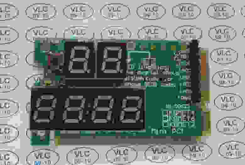
POST плата с Mini-PCI, Mini-PCI-e и LPC
Первая плата предназначена для ноутбуков (преимущественно из-за своего форм-фактора Mini; однако никто не запрещает использовать её со стационарным ПК). Она поддерживает подключение по шинам Mini PCI, Mini PCI-E и LPC.


На рисунке ниже показаны основные узлы POST платы.

Индикатор с двумя 7-сегментными светодиодами показывает собственно POST код в шестнадцатеричном представлении, его левая десятичная точка показывает, что плата подключена по шине Mini-PCI, а правая – что по шине Mini-PCI-e или LPC.
Два светодиода CLK и RST показывают статус:
- если нажата кнопка Reset компьютера, горит индикатор RST, а CLK не горит;
- рабочее состояние: когда кнопка Reset отпущена, индикатор RST не горит, а CLK мигает;
- если RST и CLK не горят, скорее всего, компьютер не поддерживает шину Mini-PCI-e, и плату нужно подключить к другой шине;
- если RST не горит, CLK мигает, но на 7-сегментном индикаторе код «00», нужно проверить, что тип шины совпадает с тем, что показывают десятичные точки на 7-сегментном индикаторе.
Интерфейс Mini-PCI ноутбука содержит 124 линии, но данная карта использует только 101, и поэтому она короче стандартного слота.
Плата использует только 7 линий интерфейса Mini-PCI-E, которые не стандартизированы (пины 8, 10, 12, 14, 16, 17 и 19). Иногда производители материнских плат выводят на них шину LPC, и тогда данная отладочная плата работает в слоте Mini-PCI-e. Если нет, то нужно использовать выделенный штыревой разъём шины LPC и провода.
Выводы LPC разъёма такие (слева направо): LFRAME#, LAD3, LAD2, LAD1, LAD0, GND, LRESET#, LCKC, 3.3V.
Обычно в ноутбуке под шину LPC нет отдельного разъёма, а имеются в лучшем случае контактные площадки на материнской плате. В таком случае придётся подпаиваться к ним. Иногда и площадок нет, но BIOS поддерживает LPC. Тогда придётся подпаиваться напрямую к чипу. Примеры чипов и схемы подключения к ним приведены в руководстве пользователя данной отладочной карты.
Руководство к данной POST карте можно скачать в приложении к статье.
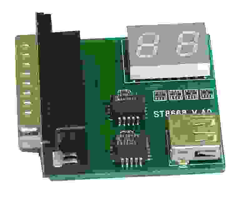
POST плата с PCI и ISA
Вторая плата предназначена для стационарных компьютеров и работает по интерфейсам ISA и PCI. Слот шины ISA не имеет ключей, и чтобы не перепутать сторону при установке POST карты в слот ISA, задняя часть коннектора помечена «REAR» (соответственно, начало коннектора – с противоположной стороны).


На отладочной плате имеется 4-символьный светодиодный индикатор. Он показывает сразу два POST кода (слева – последний, справа – предыдущий).
Кроме того, имеются 8 светодиодов. Левый столбец (сверху вниз) сообщает о наличии правильного питания на материнской плате по напряжениям:
- −12 В;
- +12 В;
- +5 В;
- +3,3 В.
Правый столбец светодиодов показывает:
- CLK – наличие тактовых импульсов на шине; должен светиться даже при отсутствии ЦП;
- IRDY – готовность устройства; загорается при обнаружении сигнала IRDY;
- FRAME – мигает при обнаружении сигнала Frame на шине PCI;
- RESET – горит при перезагрузке компьютера и примерно полсекунды после подачи питания на материнскую плату.
Функциональная кнопка S1 позволяет просматривать историю POST кодов в данном цикле загрузки компьютера. Последовательные нажатия кнопки выводят на светодиодный индикатор все коды, которые отладочная карта получила и сохранила в своей памяти. При достижении последнего кода на индикаторе появится слово «END». Долгое нажатие кнопки переводит отладочную плату в режим самопроверки. При этом на индикаторе будут меняться числа от 0000 до 9999.
Джампер JP2 рядом со звуковым пьезоизлучателем SP1 позволяет подключить внешний пьезоизлучатель (при подключении полярность не важна). Этот звуковой излучатель дублирует системный динамик, который вы слышите каждый раз при включении компьютера (если он есть). При нормальном включении компьютера динамик должен издать один короткий гудок. При сбое динамик выдаст последовательность звуковых сигналов разной длительности. По числу и длительности этих сигналов можно также судить о причине неисправности.
Как и POST коды, звуковые сигналы на материнских платах разных от разных производителей отличаются.
Ещё имеется разъём для подключения внешнего 7-сегментного дисплея и кнопки (дублирование кнопки S1).
Руководство к данной отладочной плате также можно скачать в приложении к статье.
3 Использование отладочных POST карт
Для начала необходимо выбрать подходящую POST карту, исходя из того, какие интерфейсы имеются на вашей материнской плате.
Прежде чем устанавливать любую из отладочных карт, следует обесточить компьютер. Затем установить плату в подходящий слот и включить компьютер. Наблюдать за появляющимися POST кодами и дополнительными индикаторами на плате.

В момент, когда загрузка компьютера останавливается из-за неисправности, POST коды перестают обновляться. Последний код является той проверкой, которую компьютер не может пройти.
Далее необходимо найти описание своей материнской платы и POST коды для неё.
Время на прочтение
2 мин
Количество просмотров 153K
Приветствую, дорогие хабровчане!
Не первый год занимаюсь диагностикой и реанимацией десктопов и ноутбуков, преимущественно на дому у клиента. Со временем напрашивается вывод, что с собой необходимо иметь чемодан, а возможно, даже чемоданище с комплектующими для диагностики неисправной железки. Некоторые могут мне возразить — «Можно обходиться и без комплектующих! Опыт позволяет выполнять диагностику и без них!». Это отчасти верно, но стопроцентной точности не дает, это как факт.
Опираться на POST коды спикера? Не всегда можно конкретно определить на что же он ругается. Например, один длинный два коротких сигнала спикера сигнализируют о неисправности видеосистемы, но это не всегда означает неисправность самой видеокарты. Встречаются, например, проблемы с доп. питанием на эту самую видеокарту, а это уже неисправность блока питания.
Здесь я остановлюсь и расскажу уважаемым читателям, что же такое сигналы спикера.
При включении компьютера запускается BIOS (базовая система ввода/вывода) — факт известный всем, но упомянуть будет не лишним. В составе BIOS’а есть программа под названием POST (power on self testing). Как следует из названия, программа предназначена для начальной диагностики устройств и портов материнской платы.
Процедура инициализации POST сопровождается выводом изображения на монитор:
После прохождения POST видим:
В процессе выполнения POST генерирует так называемый POST код, который записывается в специальный диагностический регистр.
И дальше управление переходит к загрузчику операционки.
Собственно, сигналы спикера являются кодами ошибок при выполнении POST, если POST выполняется без ошибок, мы слышим один короткий сигнал.
Переходим к сабжу.
POST карты.
POST карта — это плата расширения, чаще всего встречаются карты формата PCI:

Так же есть карты формата miniPCI (для ноутбуков):
И встречаются карты для LPT (требуют дополнительного питания по USB):
Имея на руках десктоп с замечательным диагнозом «не включается» (не путать с «не заводится»), чаще всего сначала последовательно отключается некритичная периферия — звуковуха, тюнер, сетевуха, харды, приводы.
Затем, если в процессе не выявлены неисправности, начинается замена комплектующих: оперативки, видеокарты, процессора (ага тот самый чемоданище с железками).
Но вот у нас есть в руках вместо чемодана с железом POST карта, мы экономя время минуем вышеописанную процедуру с заменой/отключением железа (экономим в среднем минут 40, замечу, что после отключения одной железки производится как минимум один цикл включения — выключения).
Собственно, вставляем нашу замечательную карту и наблюдаем за тем что происходит.
А происходит следующее — на табло карты у нас появляются пост коды, которые указывают нам на то, что тестируется в данный момент. Дойдя до неисправного элемента, процедура выполнения POST останавливается и на табло остается код, собсно к сабжу чаще всего прилагается мануал с POST кодами (они разнятся в зависимости от производителя и версии BIOS).
Сопоставив код ошибки с его расшифровкой, чаще всего получаем конечный диагноз, как то: неисправная память, процессор или же компонент на материнской плате.
Предполагаю написать серию статей по диагностике, если тема интересна хабровчанам.
-
Bookmarks
Quick Links
User’s Guide
Mega-Post PCI-Diagnostic Card
User’s Guide
1
Related Manuals for Compaq Mega-Post
Summary of Contents for Compaq Mega-Post
-
Page 1
User’s Guide Mega-Post PCI-Diagnostic Card User’s Guide… -
Page 2: System Requirements
Diagnostic Card in hand, you no longer have to go through tedious and time consuming process of trying to figure out what is wrong with your PC hardware. The Mega-Post PCI-Diagnostic Card will tell you exactly what is wrong with your PC in just seconds. It saves you time and money.
-
Page 3: Power On Self-Test (Post) Codes
Power Supply, 3.3-Volt. Some motherboards have 3.3V power supply to PCI slots. This indicator should be on if the motherboard supplies 3.3V power. Installing the Mega-Post PCI-Diagnostic Card Installation Procedure TO INSTALL A Diagnostic Card: Install the Diagnostic Card in any available PCI or ISA expansion slot.
-
Page 4: Post Codes
User’s Guide POST Codes When the machine is turned on, the hexadecimal display should show the various POST codes as the system executes (unless it has a rare BIOS that does not display POST codes). If the machine does not boot, system POST has detected a fatal fault and stopped. The number showing in the hexadecimal display on the Diagnostic Card is the number of the test in which POST failed.
-
Page 5
(00)Going to give control to INT 19H boot loader. (01)Processor register test about to start, and NMI to be disabled,286 reg. test about to start. (01)Processor test 1;Processor status(1FLAGS) verification; Tests the following processor status flags carry, zero, sign, overflow. The BIOS will set each of these Award flags, verify they are set then turn each flag off and verify it is off. -
Page 6
(06)ROM is enabled. Calculating ROM BIOS checksum, and waiting for Keyboard controller input buffer to be free. Calculating ROM BIOS checksum.. Video disabled and sys- tem timer test begin Video disabled and system timer counting (06)Support chipset initialize. (06)Test memory refresh toggle; RAM must be periodically refreshed in-order to Award keep the memory from decaying. -
Page 7
Phoenix&Dell (0A)Initialize CPU registers. (Beep)=1-1-3-3. Perform BIOS checksum test. 1st 64K RAM chip or data line failure multi-bit. CMOS status register initialize done. Keyboard controller command byte is written. Going to issue Pin-23,24 block- ing/ unblocking command. Going to issue pin-23,24 blocking/ nubolcking command. -
Page 8
(10)DMA controller test 0 register (10)DMA channel 1 Test. Test DMA controller 1 with AA, 55,FF,00 pattern.8237 Award DMA,channel 0 test. (10)PPI disabled, Program timers 0 & 1. Compaq Chips & Tech (10)(Beeps)=19 short, IDT,GDT failure. Phoenix&Dell (10)Initialize Power Management.(Beep)=1-2-1-1.Initia- timers.[Beep]=2-1-1 1st 64K RAM chip or data line failure-bit 0. -
Page 9
Award (16)Test 8259-2 mask bits; Verify 8259 channel 2 masked interrupt by alternate turning off and on the interrupt line. Setup Interrupt vectors. (16)Battery power was lost. Compaq Chips & Tech (16)Keyboard controller gate A20 failure. Phoenix&Dell (16)BIOS checksum.(Beep)=1-2-2-3. Coprocessor.[Beep]=2-2-3 1st 64K RAM chip or data line failure-bit 6. -
Page 10
(1E)If EISA NVM checksum is good, execute EISA initialization(EISA BIOS ONLY). Size Award system memory. (1E)Test keyboard controller. Compaq Phoenix&Dell (1E)[Beep]=2-4-3 1st 64K RAM chip or data line failure- bit E.Base 64K RAM test(16 bits). (1F)Video mode set call for mono/color begins. Mode set call for mono/color OK. -
Page 11
(27)Enable slots 7; Initialize slot 7.Setup cache control or shadow RAM. Award Compaq (27)initialize parallel printer. Phoenix&Dell (27)[Beep]=3-2-4 keyboard controller test in-progress or failure. ACER (28)Test CPU. (28)initialization before setting video mode is complete. Going for monochrome mode and color setting .Check extended memory. -
Page 12
(30)Get base memory & extended memory size. Size base And extended memory Award from 256K to 640K and extended memory above 1MB. (30)Clear 1st 128K bytes of RAM. Compaq (30)[beep]=none screen believed running w/video ROM. Dell (30)see Error Code «2C».Unexpected shutdown.[Beep]=no- ne screen believed operable. -
Page 13
(39)New cursor position read and saved. Going go display the Hit<DEL>message. Memory above 1MB initialized. (39)Check for parallel ports. Compaq (39)Reinitialize the cache.(Beep)=1-4-3-1 Phoenix (3A)Check memory, first 64K,one long beep. Reference string display is over. Going to display the Hit<ESC> massage. Memory size display initiated. This will be updated when the BIOS goes through the memory. -
Page 14
(44)Interrupts enabled(if post switch is on). Going to initialize data to check memory wrap around at 0:0. (44) Going to initialize data to check memory re-map at 0:0. Award (44)Start verify cycle if 128K RAM test. Compaq (44)Initialize BIOS interrupts.(Beep)=2-1-2-1. Verify video configuration. Phoenix ACER (45)Set up BIOS RAM . -
Page 15
(50)Write all the CMOS values currently in the BIOS stack areas back into the Award CMOS. Write CMOS; Write all CMOS values back to RAM and clear screen. (50)Check for dual freq in CMOS. Compaq Chips & Tech (50)Hardware initialize. Phoenix (50)Display CPU type and speed.(Beep)=2-2-1-1.(50)Per- form LSL instruction test.[Beep]=none Custom chip set or custom platform. -
Page 16
(59)Hit<ESC> message cleared.<Wait..> message displayed. About to start DMA and interrupt controller test. Master 8259 mask register OK, about to start slave. (59)Check existence of adapter. Compaq Chips & Tech (59)Exiting protected mode. Phoenix (59)Initialize POST display service. (5A)About to check timer and keyboard interrupt level. -
Page 17
(64)Start test real time clock. (64)BIOS ROM data area check halfway. BIOS ROM data area check to be complete. (64)Copy BIOS to shadow RAM. Compaq (64)Start test of real memory. Chips & Tech (64)Address line A20. Phoenix (64)Jump to User Patch 1.(Beep)=2-3-2-1.Shadow memory test. -
Page 18
Chips & Tech (71)Key-lock. (72)Keyboard interface test over, mouse interface test started. Compaq (72)High order address test. Chips & Tech (72)Pointing divide. Phoenix (72)Check for configuration errors.(Beep)=2-4-1-3.(72) Real time clock test. (73)Global data initialization for keyboard/mouse over. Compaq (73)Exit memory test. -
Page 19
(82)Keyboard controller interface test over. About to write command byte and Init circular buffer. Check for printer ports and put the addresses in global data area. (82)Check result received. Compaq (82)Detect and install external RS232 ports.(Beep)=3-1- 1-3.Test floppy drives. Phoenix (83)Command byte written, global data Init done. -
Page 20
Compaq (90)Start of CMOS test . Chips & Tech (90)Set-up RAM. Phoenix (90)Initialize hard-disk controller.(Beep)=3-2-1-1 (91)Floppy setup complete. Hard disk setup to be done next. Compaq (91)CMOS seems to be OK. Chips & Tech (91)CPU speed. Phoenix (91)Initialize local-bus hard-disk controller.(Beep)=3-2-1-2 (92)Hard disk setup complete. -
Page 21
Phoenix (9F)Determine number at ATA and SCSI drives. (A0)Keyboard ID command issued. Keyboard ID flag to be reset. (A0)Start of diskette tests. Compaq (A0)Set time of day .(Beep)=3-3-1-1 Phoenix (A1)Keyboard ID flag reset. Cache memory test to follow. (A1)FDC reset active (3F8H bit 2) Compaq (A2)Cache memory test over. -
Page 22
Compaq (B5)Drive error(error condition). Phoenix (B5)terminate Quiet-Boot(optional) Compaq (B6)Drive failed(failed to respond). Phoenix (B6)Check password(optional).(Beep)=3-4-2-3 Compaq (B7)CMOS RAM invalid or no fixed drives, exit. Compaq (B8)Fixed drive tests complete. Phoenix (B8)Clear global descriptor table.(Beep)=3-4-3-4 Compaq (B9)Attempt to boot diskette. Phoenix (B9)Prepare boot. -
Page 23
(CD)BAT command to keyboard controller is to be issued. (CE)Keyboard controller BAT result verified. Any initialization after KB controller. (CF)Initialization after KB controller BAT done. Keyboard command byte to be written next. Compaq (D0)Entry to clear memory routine. (D0)Interrupt handler error.(Beep)=4-2-1-1 Phoenix (D1)Keyboard controller command byte is written.
M ainboard lcd Post Card Instruction(PTI8)
 ainboard lcd Post Card Instruction(PTI8)
Introduction
PC LCD post test card Professional Version PTI8 is the computer repair tool developed by Waychan Technologies. The professional version has all the advantages of Accurate PTI6, while it has upgraded the chip solution, adapting three-level menu operation, adding hundreds of diagnostic codes (from authoritative institution). PTI8 could offer real-time monitoring on the voltage, and the professional function like key signal monitoring. With unique MutiPost technology, PCi8 is able to monitor most POST interface of most main board, and it is compatible with most of the popular main boards. Specially PCi8 has MINIPCIE, MINIPCI, LPC these three interfaces of notebook PC, which makes it new generation Mainboard LCD Post Card that is compatible with both desktop and notebook PC. PTi has two screens design, as we had feedbacks from customers that one screen is not convenient enough. PTI8 is a indispensable tool for computer repair personals.
S tructure Diagram of PTI8
PTI8 is fully compatible with PCI slots of all types of main board, it has being tested with many of the popular main boards (including brand PC and kludge PC), which involves mainstream products like INTEL and AMD (Lenovo, Asus, DELL, Toshiba , HP, etc). Also it has passed main board test with INTEL 815, INTEL 845, INTEL 865, INTEL 915, INTEL 945, INTEL 965, ATI SB600, ATI Xpress 200, ATI Xpress 1100, and AMD 480X chipset.
1. Asus P7P55D: tested with Core i7, Core i5 processor, Intel P55 chipset series.
2. HP DC7100 915G main board: LGA 775 Celeron D integrated card.
3. Asus P6T: tested with INTEL LGA 1156 series and Core i7 processor, and Intel X58 chipset.
4. Lenovo 760G motherboard M3A760M dual-core support AM3 with HDMI DDR3.
5. Asus P5Q: tested with Core2 Duo, Celeron D processors, Intel P45 series of chipsets.
6. Dell DELL Optix GX280 775-pin I915G + ICH6.
7. Master M2N_SLI: tested with AMD AM2 940 series processors, nVIDIA 560 series chipsets,
8. ASUS STRIKER: tested with INTEL LGA 7750 series processors, NVIDIA78i Series Chipset.
9. ASUS P5N7: tested with INTEL LGA 775Celeron D processor, nVIDIA Series Chipset.
10. Asus P6T: test platform INTEL LGA 1156 Series Core i5 processors, ntel X58 Chipset.
Function Menu
1, The appearance of PTI8 is shown in the picture, and the four keys are: MENU, ENTER, UP, DOWN. Before entering the menu, the key ‘MENU’ function as menu key, while it is used as back key after entering the menu; ENTER key is for entering the next menu or choose some of the functions; UP is the page key, and could be used to check the previous diagnostic code; DOWN is the page key, and could be used to check the next diagnostic code.
2, The six LED lights are 3.3V, CLK, RESET, FRAME, IRDY, SYSCLK. 3.3V is the power indicator light for PCI slot positive 3.3V voltage; CLK is the time output indicator light of PCI slot, and it shows micro light during normal condition; RESET is the reset indicator light of PCI slot, and it shines while resetting; FRAME is the FRAME indicator light of the PCI slot; IRDY is the IRDY indicator light for the PCI slot; SYSCLK is the system indicator light of this professional version, and it shines during normal condition.
3, While doing test for the desktop PC, pls make sure the card is in the desktop mode, if not, pls choose ‘desktop diagnostic’ in the ‘basic choices’ of the menu, then turn on the power and continue the test. The LED screen would show ‘current code’ and ‘previous code’ while the CPU and the key signal is working normally, and finally it will show the malfunction explanation and repair suggestions. Our Mainboard LCD Post Card can store five pieces of testing record, which could be checked by pressing ‘UP’ and ‘DOWN’. If CPU is not working or the key signal is invalid, the Mainboard LCD Post Card will show three key signal of RST, IRDY, FRAME, and suggest ‘mistake in key signal, pls check the circuit related to CPU and the power source of host machine ‘. If having notebook PC mode for the desktop PC, the Mainboard LCD Post Card will suggest’ mistake in diagnostic of desktop PC, pls check the circuit related to CPU and the power source of host machine ‘. (do choose the right mode for diagnostic, and our card could save the diagnostic type after power off, the user need not to choose the diagnostic type while start the card next time)
4, While doing test for the notebook PC, make sure the card is in the notebook mode, if not, pls choose ‘notebook PC diagnostic’ in the ‘basic choices’ of the menu, then turn on the power and continue the test. The LED screen would show ‘current code’ and ‘previous code’ while the CPU and the key signal is working normally, and finally it will show the malfunction explanation and repair suggestions. Our Mainboard LCD Post Card can store five pieces of testing record, which could be checked by pressing ‘UP’ and ‘DOWN’. If CPU is not working or the key signal is invalid, the Mainboard LCD Post Card will show three key signal of RST, IRDY, FRAME, and suggest ‘mistake in key signal, pls check the circuit related to CPU and the power source of host machine ‘. If having desktop PC mode for the notebook PC, the Mainboard LCD Post Card will suggest’ mistake in diagnostic of notebook PC, pls check the circuit related to CPU and the power source of host machine ‘. (do choose the right mode for diagnostic, and our card could save the diagnostic type after power off, the user need not to choose the diagnostic type while start the card next time)
5, One diagnostic code could relate to different malfunction for different BIOS. This Mainboard LCD Post Card professional version has all the diagnostic code of AMI WIN BIOS version, and all the codes of AWARD 6.0 version, and all the codes of Phoenix 6.0, besides all these , this professional version added hundreds of diagnostic codes. The user should choose proper type according to related BIOS. There is ‘BIOS Options’ on the main menu, after pressing ENTER, there will be choices of AMI, AWARD, PHOENIX, choose the right kind of BIOS, and the screen would suggest that the BIOS has been chosen. The choice of BIOS would be saved when power is cut off.
6, This professional version can check the validity of PCI key signal. There is ‘basic choice’ on the main menu, choose ‘signal check’, then the user can check the validity of the three signal: RST, IRDY, FRAME.
7, The real-time voltage monitoring function make sit possible to have a full understanding of how every group of key power supply. There is ‘voltage monitoring’ option on the main menu, offering the real-time monitoring results of 3.3V, 5V , and 12V, these three group of voltage.
8, The professional version offers two screen design, which makes it much more user-friendly. Try not to touch the welding spots while the two screens are working, to avoid white screen situation. If touch the welding spots by mistake and white screen appears , pls cut off the power supply and restart the card, then it will work normally again,.
The interface function of notebook PC (Optional)
The professional version of notebook Mainboard LCD Post Card had four-level PCB design, which makes the signal more stable, and makes it able to work long time in a severe environment. the types of notebook PC main board interfaces: (1) MiniPCIe (2) MiniPCI (3) LPC
Mini PCI-E interface of Mainboard LCD Post Card
Mini PCI-E is the interface that getting more and more popular among notebook PC. The Mini PCI-E interface is taking less space than the Mini PCI. Our Mainboard LCD Post Card use following pins of Mini PCI-E interface: PIN-8, PIN -10, PIN-12, PIN-14, PIN-16, PIN-17, PIN-19. Currently not all the notebook producers support such pin definition standard, so not all the notebook main board would support such interface. After series of test, we confirm that following notebook brands would support this interface. And they are HP, Lenovo, HASEE, UNIS, Acer, Fujitsu, Inventec, etc. The interface can not work with the notebook main boards that are not supporting such interface. Following are some for the testing result for reference: HP: V6000 series, including CT6 and other models; V9000 series, including AT8, AT9, and other models. Lenovo: CW3, CW4, LE4, LE5, and other models HASEE: 310,320 and other models UNIS: SYMPHONY6.0, 7.0 and other models Acer: Most models Fujitsu: PROTLAND10 other models Inventec: most models OEM by Toshiba and HP
The LPC interfaces of Mainboard LCD Post Card
from left to right, the definition of our Mainboard LCD Post Card got this interface are: PIN1-LFRAME #, PIN2-LAD3, PIN3-LAD2, PIN4-LAD1, PIN5-LAD0, PIN6-GND, PIN7-LRESET #, PIN8-LCLK, PIN9-3.3V. The interface needs fly line. Most models of the Lenovo ThinkPad series has fly line interface on their main board. LPC is the popular interface for different main boards.
For main board of IBM X60, the LPC interface is on the slot with number U39. The definitions are: A2-> LRESET #, A3-> LFRAME #, A5-> LCLK, A9-> LAD3, A10-> LAD2, A11 -> LAD1, A12-> LAD0. For IBM T6 R6 main board, the LPC interface in on the pin No. J26. The definitions are: A1-> LCLK, A3-> LFRAME #, B2-> LRESET #, B7-> LAD3, A7-> LAD2, B6 -> LAD1, A6-> LAD0 For notebook PC without fly line interface, the user need to connect the fly line with chip pin of the main board, which would require very good jointing skill from the user. Following are the ways of fly line for popular chips, such as PC97551, PC87541, PC87591, H8S/2149, W83L950D, TCPA, ect.

t he power supply and address haven’t been listed above, GND and 3.3V power supply are optional for the users. (Attention: do not connect the card with PIN9-3.3V power supply, or else the Mainboard LCD Post Card would be permanently damaged) Also the user could link the Mainboard LCD Post Card to the LPC interface BIOS ofthemainboardwith fly line, if the main board has BIOS of PLCC32 with LPC interface.
The pin definitions of LPC BIOS are: PIN2-RST #,
PIN13-LAD0,
PIN14-LAD1,
PIN15-LAD2,
PIN16-GND,
PIN17-LAD3,
PIN23-LFRAME #,
PIN25-VCC
PIN31-CLK.
Attention:
1. This professional version has Table Look-up function and the diagnostic result will show on the screen. There would appear some POST code while there are malfunction codes on the main board, so the judgment of whether the malefaction has been rightly diognoticed could only be sure with the last Mainboard LCD Post Card (that is why some 2-digit or 4 — digit card can not make proper diagnostic). We suggest the users to press UP and DOWN to check the next and previous codes, and find out the reasons for malfunction in the main board.
2. The interpretation for the codes ’00 ‘and’ FF ‘
(1) ’00 ‘or’ FF ‘appearing after a series of codes means BIOS self-check completed.
⑵ The BIOS self-check would continue if the BIOS circuit on the main board is functioning. ’00 ‘And’ FF ‘would appear at last, showing the user that self check has been completed, and will start guiding the system.
⑶ The ’00 ‘,’ FF ‘appearing right after the computer started means the main board is not working, pls check CPU or power supply.
3. There are three kinds of conventional BIOS: AMI, Award, Phoenix. The same code could be showing different kinds of meaning, so the user of our Mainboard LCD Post Card must choose relative kind of BIOS in the menu. Save the data after changing the setting.
4. The type of BIOS could be identified by main board menu or by the mark on the chip of main board BIOS, or check directly on the screen if the main board could show that. Or plug out the RAM card, the BIOS is AMI type if it stops at ‘D1’, ‘D3’, or ‘DE’; the BIOS is AWARD type if it stops at ‘C1’, ‘C2’, ‘C3’; it is Phoenix type if it stops at ‘0 A ‘ , ‘0 B ‘, or ‘0 C’.
5. Some of the PCI slots would show only part of the codes, so we suggest changing the slot when failing in obtaining diagnostic codes. Many of the Mainboard LCD Post Cards on the market could show ‘2 B ‘codes while using with high-end main boards , but our card is able to obtain all the codes.
6. The diagnostic code would be ’00 ‘while RST signal light and the CLK signal light of notebook PC is off, so the test could not continue, it’s possible that the main board of notebook PC does not support the MINIPCI-E interface, pls use other interface to continue the test.
7. If on the screen reads ‘unknown diagnostic code, pls check the parameters of main board’, pls check the BIOS setting first, try to change the BIOS setting. If Not Solved the problem is after this, pls check the website http: / / www.bioscentral.com for more support, or You can contact us directly.
8, Pls check the appendix1 for the parameters of our latest version.
9, Contact information of Waychan Technologies :www.mcufpga.com