Руководства по эксплуатации, обслуживанию и ремонту мотоциклов производства Ирбитского мотоциклетного завода

Описание устройства и руководство по эксплуатации, техническому обслуживанию и ремонту тяжелых мотоциклов моделей М-61, М-62 и К-750.
- Издательство: Физкультура и спорт
- Год издания: 1962
- Страниц: 211
- Формат: PDF
- Размер: 13,5 Mb
Описание устройства и руководство по эксплуатации и техническому обслуживанию мотоциклов модели М-72.
- Издательство: Военное издательство
- Год издания: 1948
- Страниц: 131
- Формат: PDF
- Размер: 16,6 Mb
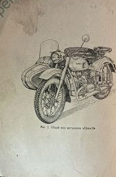
Описание устройства и руководство по эксплуатации, техническому обслуживанию и ремонту мотоциклов модели М-72.
- Издательство: Машгиз
- Год издания: 1957
- Страниц: 237
- Формат: PDF
- Размер: 5,3 Mb
Руководство по эксплуатации и техническому обслуживанию мотоциклов модели М-72.
- Издательство: Машгиз
- Год издания: 1955
- Страниц: 81
- Формат: DjVu
- Размер: 6,6 Mb

Руководство по эксплуатации и техническому обслуживанию мотоциклов модели М-72.
- Издательство: Машгиз
- Год издания: 1964
- Страниц: 42
- Формат: PDF
- Размер: 1,1 Mb

Руководство по ремонту мотоциклов модели М-72.
- Издательство: Военное издательство
- Год издания: 1950
- Страниц: 390
- Формат: DjVu
- Размер: 13,3 Mb
Описание конструкции и руководство по эксплуатации мотоциклов модели М-72.
- Издательство: Военное издательство
- Год издания: 1956
- Страниц: 163
- Формат: PDF
- Размер: 16,6 Mb
Руководство по эксплуатации и техническому обслуживанию мотоциклов модели М-72-Н.
- Издательство: Машгиз
- Год издания: 1956
- Страниц: 21
- Формат: PDF
- Размер: 2,1 Mb
Руководство на английском языке по эксплуатации и техническому обслуживанию мотоциклов Урал 2002 года выпуска.
- Издательство: ИМЗ
- Год издания: —
- Страниц: 91
- Формат: PDF
- Размер: 2,1 Mb
Руководство по эксплуатации и техническому обслуживанию мотоциклов Урал М67-36.
- Издательство: ИМЗ
- Год издания: 1984
- Страниц: 113
- Формат: PDF
- Размер: 2,4 Mb
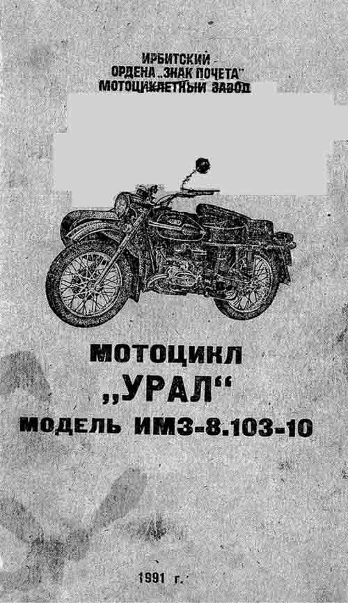
Руководство по эксплуатации и техническому обслуживанию мотоциклов Урал ИМЗ-8.103-10.
- Издательство: ИМЗ
- Год издания: 1990
- Страниц: 117
- Формат: PDF
- Размер: 73,7 Mb
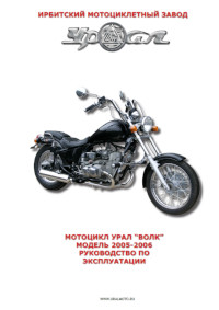
Руководство по эксплуатации и техническому обслуживанию мотоциклов Урал «Волк» 2005-2006 годов выпуска.
- Издательство: ИМЗ
- Год издания: —
- Страниц: 51
- Формат: PDF
- Размер: 4,9 Mb

Руководство по эксплуатации и техническому обслуживанию мотоциклов Урал моделей Турист, Спортсмен, Классик, Gear-Up и Ретро 2009 года выпуска.
- Издательство: ИМЗ
- Год издания: —
- Страниц: 52
- Формат: PDF
- Размер: 6,4 Mb

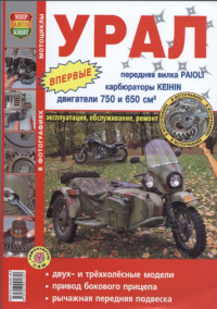
Руководство по ремонту тяжелых мотоциклов моделей К-750М, Урал и Днепр.
- Издательство: Машиностроение
- Год издания: 1986
- Страниц: 305
- Формат: PDF
- Размер: 29,4 Mb
Руководство по ремонту тяжелых мотоциклов Урал и Днепр.
- Издательство: Россельхозиздат
- Год издания: 1987
- Страниц: 215
- Формат: PDF
- Размер: 27,0 Mb

Руководство по эксплуатации и ремонту тяжелых мотоциклов Урал и Днепр.
- Издательство: Ранок
- Год издания: 2001
- Страниц: 237
- Формат: PDF
- Размер: 41,3 Mb

Руководство по эксплуатации, описание устройства и каталог запчастей мотоциклов Урал.
- Издательство: ИП Морозов
- Год издания: 2004
- Страниц: 81
- Формат: DjVu
- Размер: 3,1 Mb
Руководство по эксплуатации, техническому обслуживанию и ремонту мотоциклов Урал.
- Издательство: Мир Автокниг
- Год издания: 2008
- Страниц: 275
- Формат: PDF
- Размер: 63,9 Mb
Руководство по эксплуатации, техническому обслуживанию и ремонту мотоциклов производства Ирбитского мотоциклетного завода.
- Издательство: Машиностроение
- Год издания: 1986
- Страниц: 119
- Формат: PDF
- Размер: 8,2 Mb

Руководства по эксплуатации
Руководство по эксплуатации М-72

Руководство по эксплуатации М-61,М-62,К-750
Руководство по эксплуатации М-63
Руководство по эксплуатации М-67-36
Руководство по эксплуатации ИМЗ-8.103-10
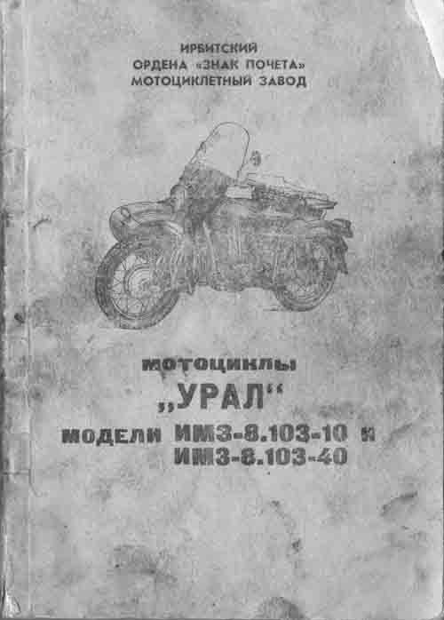
Руководство ИМЗ-8.103-10/ИМЗ-8.103-40
Книги по ремонту

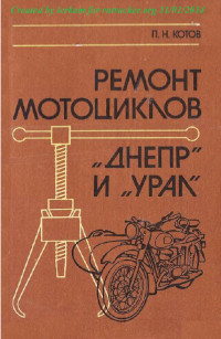
Ремонт тяжелых мотоциклов П.Н.Котов, А.А.Капустин
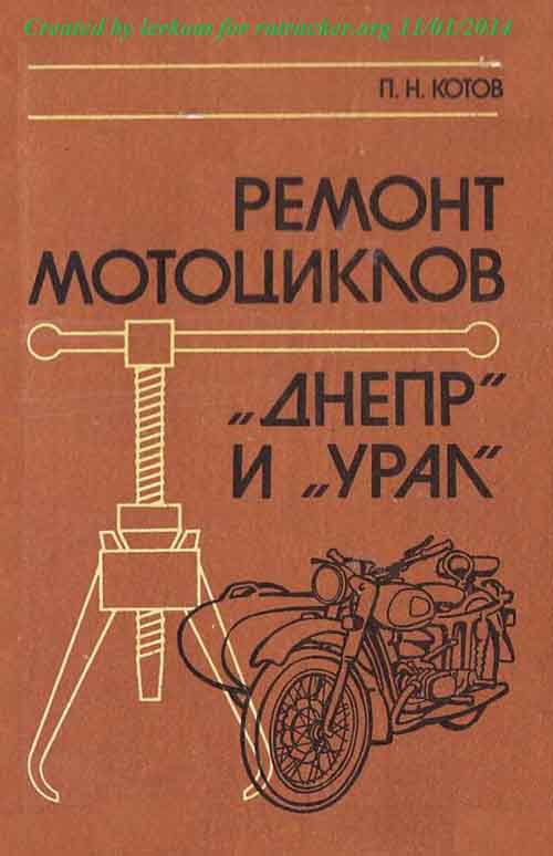
Ремонт мотоциклов «Урал», «Днепр» П.Н.Котов
Каталог мотоциклов
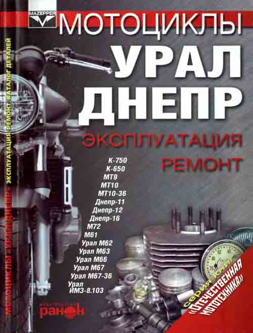
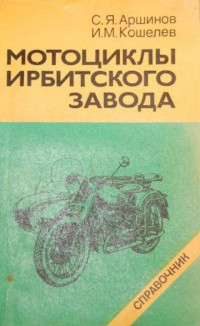
Мотоциклы «Урал», «Днепр» эксплуатация, ремонт
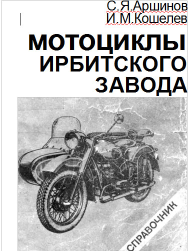
Мотоциклы Ирбитского завода, справочник
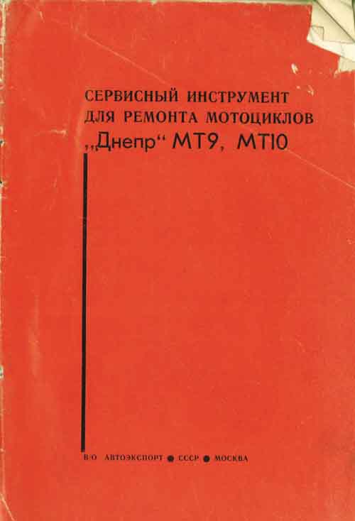
Инструмент для ремонта мотоциклов
- Manuals
- Brands
- URAL Motorcycles Manuals
- Motorcycle
- Gear Up 2022
- Owner’s manual
-
Bookmarks
Quick Links
2022 OWNERS MANUAL
Gear Up_LH cT_LH
imz-ural.com.au
Related Manuals for URAL Motorcycles Gear Up 2022
Summary of Contents for URAL Motorcycles Gear Up 2022
-
Page 1
2022 OWNERS MANUAL Gear Up_LH cT_LH imz-ural.com.au… -
Page 2
Intentionally left blank… -
Page 3
INTRODUCTION Welcome to the URAL Motorcycling Family! Your Ural has been built by the Irbit Motorcycle Factory in Russia. This Ural motorcycle conforms to all applicable Vehicle Safety and Environmental Protection standards effective on the date of manufacture. This manual covers the Gear-Up_LH and cT_LH models and has been prepared to acquaint you with the operation, care and maintenance of your motorcycle and to provide you with important safety information. -
Page 4
IMPORTANT SAFTEY INFORMATION WE STRONGLY SUGGEST THAT YOU READ THIS MANUAL COMPLETELY PRIOR TO RIDING YOUR NEW URAL MOTORCYCLE. THIS MANUAL CONTAINS INFORMATION AND ADVICE THAT WILL HELP YOU PROPERLY OPERATE AND MAINTAIN YOUR MOTORCYCLE. PLEASE PAY SPECIAL ATTENTION TO NOTICES IN THIS MANUAL MARKED AS FOLLOWS: CAUTION INDICATES POSSIBILITY OF EQUIPMENT FAILURE THAT MAY RESULT IN YOUR MOTORCYLE BEING UNSAFE TO OPERATE IF INSTRUCTIONS ARE NOT FOLLOWED… -
Page 5
Table of Contents Section General Information Motorcycle Controls and Instrumentation Motorcycle Operation Service & Maintenance Sections Lubrication Engine & Chassis Maintenance Electrical EFI Troubleshooting Consumer Information Sections Warranty Information Emission Control Information Owner Documents Schematics… -
Page 6
1. General Information Page Service Rules Model Identification Model Specifications Torque Chart Clearance and Adjustment Specifications Tire Data Periodic Maintenance Chart Motorcycle Storage and Care… -
Page 7
SERVICE RULES 1. Always wear proper safety equipment including but not limited to safety glasses and gloves. 2. Allow your motorcycle to cool down completely prior to servicing to avoid getting burned. 3. Always use genuine Ural or Ural recommended parts, fluids and components when servicing your motorcycle. -
Page 8
MODEL IDENTIFICATION VIN (Vehicle Identification Number) The VIN label is located on the right-hand frame down tube and is also stamped on the frame directly above the label. List Your VIN Here Engine Number The engine number is stamped on the left side of the engine. -
Page 9
MODEL SPECIFICATIONS Model Gear Up / Ranger Model Gear Up Engine and transmission Engine and transmission Displacement, cc Displacement, cc OHV air cooled 2 cylinder 4 stroke «boxer» OHV air cooled 2 cylinder 4 stroke «boxer» Engine type OHV air cooled 2 cylinder 4 stroke «boxer» OHV air cooled 2 cylinder 4 stroke «boxer»… -
Page 10
TORQUE SPECIFICATIONS Chassis Newton Meters Foot Pounds Fork Pinch Bolts (Upper and Lower Bridges) 36.9 Upper fork Nuts 22.1 Steering Head Nut 25.1 Front fork Upper Shock Bolts 36.1 Front Axle Bolt 36.9 Front Axle Pinch Bolts (swingarm) 17.7 Upper Shock Bolts 22.1 Lower Shock Bolts 36.1… -
Page 11
CLEARANCES Location Millimeters Inches Intake Valves (Cold) 0.10 0.004 Exhaust Valves (Cold) 0.15 0.006 Spark Plug Electrode 1.00 0.04 Minimum Tread Depth 3.175 0.125 Minimum Brake Pad Thickness 0.04 FREE PLAY & ADJUSTMENTS Location Millimeters Inches Front Brake Lever 5 to 8 0.2 to 0.3 Clutch Lever 5 to 8… -
Page 12
PERIODIC MAINTENANCE CHART Description Odometer reading, miles (km) 310 (500) 3125 (5000) 6250 (10000) 9375 (15000) 12500 (20000) 15625 (25000) 18750 (30000) Check the painted and chromed surfaces for dents, scratches and rust Engine oil* Oil filter* Final drive and gearbox oil Check valve clearance Check tightness of the cylinder stud nuts Spark plugs… -
Page 13
MOTORCYCLE STORAGE AND CARE Storage If you will be storing your motorcycle for the winter or long term, take the following steps: 1. The motorcycle should be cleaned. 2. Check all fluid levels and add as necessary. 3. Check tire pressure. 4. -
Page 14
2. Motorcycle Controls & Instrumentation Page Hand Controls Foot Controls Ignition Switch Indicator Lamps Speedometer Functions Speedometer Operation Parking Brake Reverse Pedal Kick Starter 2wd Engagement Lever Hydraulic Spring Shock Absorbers Hydraulic Steering Damper… -
Page 15
HAND CONTROLS Clutch Lever Pulling the clutch lever will disengage the Front Brake Lever clutch while releasing the lever will engage Pulling the lever will actuate the front the clutch. brakes. High Beam Switch Toggle the switch forward to turn on the WARNING high beam and toggle back for “Flash to IF THE BRAKE LEVER FEELS SPONGY DO NOT… -
Page 16
FOOT CONTROLS Shift Lever This is a heel-toe type shifter. To upshift use the heel portion of the shift lever, to down shift use the toe portion of the shifter. Rear Brake Lever Pressing the rear brake lever actuates the rear and sidecar brakes. -
Page 17
IGNITION SWITCH (3 Position Switch) In the “Off” position the engine cannot be started. In the “On” position the engine can be started and all electrical functions can be used. In the “Park” position only the running lamps (not including headlight) are illuminated. INDICATOR LAMPS 1. -
Page 18
SPEEDOMETER FUNCTIONS Needle Speedometer: Indicates speed by analogue needle. RPM: Digital Tachometer NOT ACTIVE MAX RPM: Maximum Tachometer NOT ACTIVE SPD: Speedometer Displays speed in MPH. MAX SPD: Maximum Speed Meter Displays highest speed achieved since last reset operation. AVG: Average Speed Meter Calculates average speed from last RESET. -
Page 19
SPEEDOMETER OPERATION MODE Button Press the MODE button to move from one function screen to another. RESET Button Press the reset button to cycle through functions in reverse order. Data Resetting 1. Press MODE or RESET button to reach the desired screen then press RESET button for 2 seconds to reset TRIP 2, MAX SPD, MAX RPM and MAX TEMP data from stored values to… -
Page 20
PARKING BRAKE Parking Brake Lever The parking brake lever is located on the left handle bar. Pull the handle to the left lock position to set the parking brake. Release the parking brake by pushing the lever to the right position as shown. CAUTION OPERATING THE MOTORCYCLE WHILE THE PARKING BRAKE IS ENGAGED CAN… -
Page 21
KICK START LEVER Kick Start Lever To use the kick start lever rapidly press the lever downward with your foot as shown. WARNING WHEN USING THE KICK STARTER ALWAYS BE SURE THE GEARBOX IS IN NEUTRAL. 2WD ENGAGEMENT LEVER (Gear-Up_LH) 2wd Engagement Lever Shift the lever into the rear locked position to engage 2wd. -
Page 22
HYDRAULIC SPRING SHOCK ABSORBERS Adjustable Shock Absorbers The shock absorbers have 7 preload adjustments. Rotate the adjustment ring counter clockwise as shown to increase spring preload using the supplied wrench in your tool kit. HYDRAULIC STEERING DAMPER Adjustable Damper (16 Position) The steering damper is fully adjustable to accommodate different riding styles and conditions. -
Page 23
3. Motorcycle Operation Page Pre-ride Inspections Initial Ride Instructions Sidecar Safety Starting Procedures Run-In Motorcycle Use and Loading… -
Page 24
PRE-RIDE INSPECTIONS Prior to each ride you should inspect the motorcycle’s technical condition for safety. Use the following pre-ride inspection list to ensure your motorcycle is safe and ready to ride. 1. Check the oil level. Low oil level causes premature wear and possible engine damage. -
Page 25
SIDECAR SAFETY The Ural sidecar motorcycle, since it has three wheels, behaves quite differently from either a solo motorcycle or a car. For these reasons the following label has been attached to your motorcycle tank: WARNING: LEFT-HAND AND RIGHT-HAND TURNS MAY BE DANGEROUS. EXCESSIVE SPEED AND AN UNWEIGHTED SIDECAR MUST BE AVOIDED. -
Page 26
SIDECAR SAFETY (CONT.) If, after gaining proficiency with the Ural, you plan to drive on the street with an empty sidecar practice maneuvers with an empty sidecar. You’ll find that the sidecar will lift much more readily when it is empty, especially if you enter a decreasing radius turn (such as a freeway off ramp) at too high a speed. -
Page 27
STARTING THE ENGINE WHEN COLD Use the following instructions when starting a cold engine: 1. Check that you have enough fuel. 2. Switch ignition on. 3. Be sure the transmission is in neutral. 4. Switch the kill switch to run. 5. -
Page 28
ENGINE RUN-IN During the first 1000 km/620 miles it is important not to overload or over rev the engine while riding. To ensure proper break-in you should ride the motorcycle conservatively at varying speeds and loads. Use the following guidelines during the first 1000 km/620 miles prior to the initial break-in service: 1. -
Page 29
Allow the motor to cool at fill-ups. Take a break before resuming on a long trip. Give your Ural 20 minutes to cool for every 2 hours of use. Long Distance — Ural motorcycles are very capable of long distances if routine maintenance, rate of speed and the load are adjusted accordingly based on the conditions. -
Page 30
Nuts, bolts, screws and other retaining fasteners that may have loosened or been lost due to vibration. Tyres, tubes, spokes, wheel rims, shocks, steering damper, steering head bearings and swing arm pivot points. Clutch wear, cable stretch, brake pad wear, electrical connections and lighting. Load — The max permissible weight should be considered when planning a trip, choosing a route and while loading the outfit. -
Page 31
Avoid “piling on” cargo in any location of the outfit that will act as a sail, increase wind drag and increase strain on the drive train. Unbalanced loads will change the handling characteristics in turns, while cornering and while braking. Optimise loading of cargo for better handling and safer operation. -
Page 32
Look at your dipstick, has oil consumption increased? The engine can use 16-26 milliliters of oil every 150 km / 90 miles depending on riding conditions. Do you hear anything out of the ordinary? Are the brakes squeaking? A good running Ural has been compared to a sewing machine. -
Page 33
4. Lubrication Page Recommended Fluids, Lubricants & Capacities Lubrication Diagram Lubrication Points Engine oil and filter replacement Gearbox oil replacement Final drive oil replacement Drive Shaft Lubrication Cable Lubrication 4-10… -
Page 34
Wheel Axles Motul Tech Grease 300 Brake Linkage and Pivots Motul Tech Grease 300 Cables Motul E.Z. Lube NOTE URAL MOTORCYCLES EXCLUSIVLEY USES MOTUL FLUIDS AND LUBRICANTS DURING INITIAL ASSEMBLY. URAL MOTORCYCLES RECOMENDS MOTUL FLUIDS AND LUBRICANTS FOR ALL SERVICE INTERVALS. -
Page 35
LUBRICATION DIAGRAM… -
Page 36
LUBRICATION POINTS Diagram Position Location Type Engine Oil Fill Motul 3000 4T 20w50 Gearbox Oil Fill Motul Gear 300 SAE 75W90 Final Drive Oil Fill Motul Gear 300 SAE 75W90 Steering Head Bearing Motul Tech Grease 300 Final Drive Output Spines Motul Moly Grease Sidecar Drive Shaft Splines (2wd) Motul Moly Grease… -
Page 37
ENGINE OIL &FILTER REPLACEMENT Step 1 Place a drain pan under the oil sump and remove the drain plug using a 17mm socket wrench. Step 2 With the drain pan in place remove the oil filter. NOTE AN OIL FILTER WRENCH MAY BE REQUIRED FOR REMOVAL CAUTION BE SURE TO REMOVE THE OIL FILTER SEALING… -
Page 38
ENGINE OIL & FILTER REPLACEMENT (CONT.) Step 5 Lightly lubricate the new oil filter sealing ring with fresh oil and install filter tightening approximately 3/4 turn after seat of seal. CAUTION DO NOT OVER-TIGHTEN THE OIL FILTER Step 6 Fill engine with 2.6L of recommended motor oil Step 7 Start the engine and let run for 30 seconds, confirming you have no oil leaks at filter. -
Page 39
GEARBOX OIL REPLACEMENT Step 1 Place a drain pan under the gearbox and remove drain plug using a 17mm socket wrench. Step 2 Be sure to clean any metal contaminates from the drain plug and replace the drain plug sealing washer. -
Page 40
FINAL DRIVE OIL REPLACEMENT Step 1 Place a drain pan under the final drive and remove the drain plug using a 17mm socket wrench. Step 2 Be sure to clean any metal contaminates from the drain plug and replace the drain plug sealing washer. -
Page 41
DRIVE SHAFT & SPLINE LUBRICATION Final Drive Shaft U-Joints should be lubricated with grease using a grease gun. The rear drive shaft has one grease zerk located at the u-joint; grease this joint per the maintenance intervals or after off road use. Sidecar Drive Shaft On 2wd models only the sidecar drive shaft has two grease zerks located at each u-joint;… -
Page 42
CABLE LUBRICATION All cables including the clutch, speedometer, throttle, and parking brake cables should be lubricated with Motul E.Z. Lube per the maintenance intervals. You should also lubricate all cables before and after extended periods of storage and/or after off road use. To lubricate the cables, pull back the protective covers and apply lube directly to the cable as shown. -
Page 43
5. Engine & Chassis Maintenance Page Air filter Inspection & Replacement Valve Train Inspection & Adjustment Front Brake System Maintenance Rear Brake System Maintenance Parking Brake Adjustment Sidecar Brake System Maintenance 5-10 Front Wheel Removal & Installation 5-11 Rear Wheel cT_LH (1WD) Removal & 5-15 Installation Rear Wheel Gear Up_LH (2WD) Removal &… -
Page 44
AIR FILTER INSPECTION & REPLACEMENT Step 1 Remove the four retaining bolts from the air box lid using a 5mm hex wrench. Step 2 Carefully remove the air box lid by lifting the right side and sliding the lid to the left. Be very careful not to pull wiring and cables near the air box inlet. -
Page 45
VALVE TRAIN INSPECTION & ADJUSTMENT Step 1 Starting with the left side cylinder, remove the valve cover and clean any contaminants found inside with a shop towel. Step 2 Remove the timing plug located on the right side of the engine case. Slowly rotate the engine using the kick start lever until both valves are closed and the TDC (top dead center) mark located on the flywheel is centered in the… -
Page 46
VALVE TRAIN INSPECTION & ADJUSTMENT (CONT.) Step 4 If the free play clearance is not within specifications adjust as necessary. First loosen the jam nut and turn the adjustment bolt. Step 5 After adjustment reconfirm the clearance is within specifications. Step 6 Replace the valve cover gasket, bolt seals and re- torque the valve cover bolts. -
Page 47
FRONT BRAKE SYSTEM MAINTENANCE Step 1 Remove the retaining pin safety clips. Step 2 Carefully drive the retaining pins out of the caliper using a small punch or drift. Step 3 Remove the brake pads by pulling them out the top of the caliper. -
Page 48
FRONT BRAKE SYSTEM MAINTENANCE (CONT.) Step 4 Inspect the brake pads and replace as needed. NOTE MINIMUM PAD THICKNESS IS 1MM Step 5 Re-install brake pads in reverse order. Be sure to fully seat the retaining pins and install the safety clips. Step 6 Confirm the brake fluid level is full in the reservoir and add as needed to FULL line. -
Page 49
REAR BRAKE SYSTEM MAINTENANCE Step 1 Place the bike on the center stand. Remove lower shock mounting bolt and swing the shock back to access brake caliper. Step 2 Remove the caliper mounting bolts and remove the caliper. Step 3 Remove the caliper safety clip and carefully remove the retaining pin out of the caliper. -
Page 50
REAR BRAKE SYSTEM MAINTENANCE (CONT.) Step 4 Remove and inspect the brake pad, replace as needed. NOTE MINIMUM PAD THICKNESS IS 1MM Step 5 Re-install brake pads in reverse order. DO NOT forget to install the safety clip. Step 6 Confirm the brake fluid level is full in the reservoir and add as needed to FULL line. -
Page 51
PARKING BRAKE ADJUSTMENT Step 1 Locate the cable adjuster connected to the parking brake handle and be sure the parking brake is in the “off” position. Step 2 Adjust the cable to remove excess free play by tightening lower adjustment nut. NOTE ADJUST CABLE FOR MINIMAL FREEPLAY WITHOUT DRAG. -
Page 52
SIDECAR BRAKE SYSTEM MAINTENANCE Step 1 Remove the caliper mounting bolts. Step 2 Remove the caliper from the sidecar swing arm. Step 3 Remove the caliper safety clip and carefully drive the retaining pin out of the caliper with a punch or drift. -
Page 53
SIDECAR BRAKE SYSTEM MAINTENANCE (CONT.) Step 4 Remove the brake pads by pulling them out of the bottom of the caliper. Step 5 Inspect the brake pads and replace as needed. NOTE MINIMUM PAD THICKNESS IS 1MM Step 6 Re-install the brake pads and caliper in reverse order. -
Page 54
FRONT WHEEL REMOVAL & INSTALLATION Step 1 Raise front wheel off the ground Step2 Remove the lower caliper mounting bracket bolts. Step 3 Loosen the front axle bolt. NOTE FRONT AXLE BOLT IS LEFT HANDED TRHEADS 5-12… -
Page 55
FRONT WHEEL REMOVAL & INSTALLATION (CONT.) Step 4 Loosen the 2 axle pinch bolts. Step 5 Remove the axle from the wheel. Remove the front wheel with the caliper bracket. Step 6 To re-install the wheel place the caliper mount into the wheel first Step 7 Position the wheel on the bike and install the… -
Page 56
FRONT WHEEL REMOVAL & INSTALLATION (CONT.) Step 8 Reinstall and tighten the axle bolt. NOTE FRONT AXLE BOLT IS LEFT HANDED TRHEADS Step 9 Tighten the 2 axle pinch bolts according to specification. Step 10 Re-attach the caliper with mounting brackets and tighten according to specification. -
Page 57
REAR WHEEL cT_LH (1WD) REMOVAL & INSTALLATION Step 1 Place the motorcycle on the center stand. Step 2 Remove the parking brake caliper using a 5mm hex key wrench. Step 3 Allow the parking brake caliper to drop down and out of the way. 5-15… -
Page 58
REAR WHEEL cT_LH (1WD) REMOVAL & INSTALLATION (CONT.) Step 4 Loosen both brake caliper mounting bolts using a 17mm wrench. Step 5 Remove the axle nut. Step 6 Loosen the axle pinch bolt. Remove the axle. 5-16… -
Page 59
REAR WHEEL cT_LH (1WD) REMOVAL & INSTALLATION (CONT.) Step 7 Pull brake caliper mounting plate back and remove caliper bolts. Step 8 Remove brake mounting plate. Step 9 Remove the rear wheel by tilting it outwards towards you and rolling it back as shown. NOTE Re-install the rear wheel in reverse order. -
Page 60
REAR WHEEL GEAR UP_LH (2WD) REMOVAL & INSTALLATION Step 1 Put the motorcycle on the central stand. Remove final drive cover allowing access to wheel axle bolts. Step 2 Remove two bolts from wheel axle Step 3 Remove sidecar drive shaft from rear swing arm hub allowing access to the wheel axle nut. -
Page 61
REAR WHEEL GEAR UP_LH (2WD) REMOVAL & INSTALLATION (CONT.) Step 4 Remove tie-wrap from the central pipe and release parking brake cable and rear brake hose Step 5 Remove two bolts from parking brake caliper and remove parking brake caliper Step 6 Remove the axle nut 5-19… -
Page 62
REAR WHEEL GEAR UP_LH (2WD) REMOVAL & INSTALLATION (CONT.) Step 7 Remove the axle. Step 8 Remove rear brake caliper with bracket 5-20… -
Page 63
REAR WHEEL GEAR UP_LH (2WD) REMOVAL & INSTALLATION (CONT.) Step 9 Remove the rear wheel by tilting it outwards towards you and rolling it back NOTE Re-install the rear wheel in reverse order. Torque all fasteners to specification. 5-21… -
Page 64
SIDECAR WHEEL REMOVAL & INSTALLATION Step 1 Remove the sidecar brake caliper. Step 2 Carefully remove the sidecar hub cap. Remove the cover by hand or pry bar Step 3 Remove the axle cotter pin and axle nut. Step 4 Re-install the sidecar wheel in reverse order. -
Page 65
USING THE SPARE WHEEL – refer Separate Instructions for LH Sidecar Bikes NOTE THE SPARE WHEEL COMES EQUIPPED FOR USE ON THE REAR POSITION. Step 1 Remove the rear wheel and rear brake rotor. Step 2 Install the brake rotor on the spare wheel and torque to specification. -
Page 66
USING THE SPARE WHEEL How to Install Spare Wheel to Front or Sidecar Position NB. When removing front wheel — If shims and/or spacers are present when loosening the front brake caliper from the caliper mounting bracket, the shims and/or spacers will need to be re-installed in the exact same location as they were removed. -
Page 67
Remove the spacer and retaining ring Remove spacer and disk holder from opposite side of spare wheel 5-25… -
Page 68
Fit Disk Holder removed from Front or Sidecar Wheel to Spare and Insert Supplied Long Spacer Fit the supplied short spacer and retaining ring to opposite side Refit splined flange Follow Instructions to Refit Wheel to Front or Sidecar Position as per Owner’s Manual Instructions 5-26… -
Page 69
WHEEL SPOKE MAINTENANCE The wheel spokes should be checked on a regular basis and per the maintenance intervals. Check spoke tension by lightly tapping each spoke and listening to the ring. Loose spokes will make a low flat sound. Step 1 Tap each spoke and compare the sound from one to another. -
Page 70
WHEEL BEARINGS REPLACEMENT & DIAGRAMS The wheel bearings are sealed type and cannot be serviced, only replaced. The bearings should be inspected and replaced per the maintenance intervals. Step 1 Remove the wheel. Step 2 Remove the collars and retaining clips. Step 3 Carefully drive the bearings out of the hub and replace. -
Page 71
TYRE & TUBE REPLACEMENT Step 1 Remove the valve stem and deflate the tyre. Step 2 Using the provided tire spoons in your tool kit carefully remove one side of the tyre from the rim. Step 3 Remove the tube from the tyre. Step 4 Remove the tyre from the rim. -
Page 72
SIDECAR ALIGNMENT The sidecar should be installed in a definite position relative to the motorcycle. The position is determined by the camber and toe-in of the motorcycle and the side car wheels. An incorrectly aligned side car will drag the motorcycle to either side and cause extensive tire wear. -
Page 73
SIDECAR ALIGNMENT DIAGRAM 5-31… -
Page 74
6. Electrical Page Lamp & Bulb Replacement Battery Maintenance & Replacement Fuse & Relay Locations Sidecar Fuse & Relay Locations 6-10 Starter 6-11 Alternator 6-11 ECU Data Port 6-11… -
Page 75
LAMP & BULB REPLACEMENT (HEADLIGHT) Headlight Replacement Step 1 Remove the lamp retaining ring screw and pull the lamp out of the bucket. Step 2 Disconnect the lamp. Step 3 Carefully remove the lamp retaining clips and replace lamp. Step 4 Re-install in reverse order. -
Page 76
LAMP & BULB REPLACEMENT (TAIL LIGHT) Tail Light Replacement Step 1 Remove the tail light lens retaining screws. Step 2 Inspect and replace bulbs as needed. The upper bulb in the running/brake lamp and the lower is the license plate lamp. Step 3 To remove the bulb twist and pull. -
Page 77
LAMP & BULB REPLACEMENT (TURN SIGNALS) Turn Signal Bulb Replacement Step 1 Remove the turn signal lens retaining screws. Step 2 Inspect and replace bulbs as needed. Step 3 To remove the bulb twist and pull. Step 4 Re-install the bulbs in reverse order. NOTE TO HELP PREVENT CORODED CONTACTS USE DIELECTRIC GREASE. -
Page 78
LAMP & BULB REPLACEMENT (SIDECAR LAMPS) Sidecar Lamps Step 1 Remove the lens retaining screws. Step 2 Inspect and replace bulbs as needed. Step 3 To remove the bulb twist and pull. Step 4 Be sure to re-install the lens gasket. Step 5 Re-install the bulbs in reverse order. -
Page 79
BATTERY MAINTENANCE Stock battery on the motorcycle should function at ambient air temperature from -40°C to plus 60°C/ 40°F to 140°F. As the battery is in service: Regularly check the voltage for 13.8 — 14.2 V Do not allow the battery to discharge. Coat bolts, nuts, washers and tips with petroleum jelly or battery grease. -
Page 80
BATTERY REPLACEMENT Step 1 Disconnect the white negative (-) battery cable. Step 2 Disconnect the positive (+) battery cable Step 3 Remove the battery hold down straps. Step 4 Loosen both the upper and lower starter bolts to allow clearance for battery removal. CAUTION ALWAYS DISCONNECT THE NEGATIVE (-) BATTERY CABLE FIRST TO AVOID SHORTING… -
Page 81
BATTERY REPLACEMENT (CONT.) Step 5 Carefully slide the battery out between the frame tube and air box. Step 6 Re-install in reverse order by sliding the battery back into place and reconnecting all straps and cables. Step 7 Be sure to re-tighten the starter bolts. CAUTION ALWAYS RECONNECT THE POSITIVE (+) BATTERY CABLE FIRST TO AVOID SPARKS. -
Page 82
FUSE & RELAY LOCATIONS Fuse Box Main The main motorcycle fuse box is located under the right-side panel. Fuse Box Diagram This diagram shows the position and function for each fuse and relay in the fuse box. 1. ECU Power 2. -
Page 83
FUSE & RELAY LOCATIONS (CONT.) Turn Signal Relay The turn signal relay is located behind the headlight bucket. To access this relay you must first remove the headlight bucket assembly. SIDECAR FUSE & RELAY LOCATIONS Fuse Box Sidecar The sidecar fuse box is located on the right-hand interior body panel of the sidecar. -
Page 84
ELECTRIC STARTER The starter must provide 300-400 rpm to start the engine and requires a well maintained battery. If battery is below required the voltage the electric starter may not operate efficiently. If the battery becomes low you may need to use the kick starter. ALTERNATOR This motorcycle is equipped with a Denso Alternator. -
Page 85
7. EFI Troubleshooting Page Engine Management (MIL Blink Codes) Service Notes… -
Page 86
URAL ENGINE MANAGEMENT SYSTEM BLINK DIAGNOSTICS Introduction A basic blink code system has been implemented on the Ural EFI bikes to aid EMS (Engine Management System) diagnostics without the need for an additional computer diagnostic tool, greatly helping the user when during travels. -
Page 87
Blink Fault Code Fault Description MIL Activation Criteria Code P0107 Pressure sensor open or short to GND Detected circuit open P0108 Pressure sensor short to battery Detected circuit short to battery P0117 Engine temp sensor short to ground Detected circuit short to GND P0118 Engine temp sensor open Detected circuit open… -
Page 88
SERVICE NOTES… -
Page 89
8. Warranty Information Page Warranty Agreement Warranty Disclaimers Extended Warranty Spare Parts and Accessories Warranty… -
Page 90
Warranty Time Period for Current Model Year Duration of Ural Motorcycles Limited Warranty is 24 months, starting with the earlier of (a) the date the motorcycle is sold to the first retail purchaser and the warranty registration card is received by Ural Motorcycles, or (b) after 12 months in the selling dealer’s inventory. -
Page 91
WARRANTY DISCLAIMERS LIMITATIONS & EXCLUSIONS Ural Motorcycles Disclaims Any Responsibility For: Loss of time due to warrantable issues and/or repairs. Loss of use of motorcycle dues to warrantable repairs. Transportation expenses including, but not limited to, towing and/or rentals. Any other incidental or consequential damages and/or expenses. -
Page 92
Submit warranty claims to Ural Motorcycles within 10 business days of the repair date. Send failed parts and/or parts assemblies for an inspection to Ural Motorcycles within 3 (three) business days upon Ural Motorcycle’s request at Ural Motorcycles shipping expense. -
Page 93
There is no mileage limitation. SPARE PARTS AND ACCESSORIES WARRANTY Ural Motorcycles provides limited warranty for spare parts and accessories for the following period of time starting from the time of purchase of the parts by a dealer or retail customer: Engine –… -
Page 94
9. Emission Control Information Page Crankcase Emission Diagram… -
Page 95
CRANKCASE EMISSION DIAGRAM CLOSED CRANKCASE: No crankcase emissions will be discharged directly into the ambient atmosphere throughout the useful life by any vehicle to be covered by EPA Certification. Crankcase exhaust emitted by the timed breather is routed to the air filter box and ends prior to the filter. -
Page 96
10. Owner’s Documents New Owner Form New Address Form… -
Page 97
Intentionally left blank… -
Page 98
NEW OWNER FORM To transfer warranty / register with Ural when purchasing a pre-owned Ural Motorcycle, please fill out this form and mail to the address below. This will ensure that you will benefit from any remaining warranty coverage. Check here if you also want to receive newsletters and other promotional materials from Ural ** VEHICLE IDENTIFICATION NUMBER NEW OWNER’S NAME _________________________________________________________________ ADDRESS ___________________________________________________________________________… -
Page 99
Intentionally left blank… -
Page 100
NEW ADDRESS FORM If you move, please fill out the form and mail to the address below. This will insure that you continue to receive all correspondence from Irbit Motorworks of America. VEHICLE IDENTIFICATION NUMBER ___________________________________________________________________________ OWNER’S NAME_____________________________________________________________ OLD ADDRESS_____________________________________________________________________ CITY___________________________STATE________________________POSTCODE____________ MY NEW ADDRESS IS: NEW ADDRESS__________________________________________________________________… -
Page 101
Intentionally left blank… -
Page 102
11. Schematics Wiring Diagram…
This manual is also suitable for:
Ct 2022
![]()
4-я Красноармейская, 2А
Санкт-Петербург, 190005
Email: info@lenmoto.ru
Телефон: +7 (921) 930-81-18
Телефон: +7 (911) 928-08-06
Компания ЛенМото
Запчасти, аксессуары, экипировка, тюнинг для мотоциклов, скутеров, квадроциклов, снегоходов, багги, гидроциклов, катеров и лодочных моторов.
Подпишитесь на наши новости
Подписаться
Урал М-62, М-63, М-66, М67-36
- Цитата
Сообщение doom » 20 мар 2015, 04:05
Руководство по эксплуатации, техобслуживанию и ремонту мотоциклов Урал М-62, М-63, М-66, М67-36
 14857 просмотров")
Язык: Русский
Формат: PDF
Размер: 30 Мб
Скачать документацию Урал М-62/М-63/М-66/М67-36
Пароль для распаковки архива: avtoproblem-net.ru