-
Contents
-
Table of Contents
-
Troubleshooting
-
Bookmarks
Related Manuals for Yamaha Thunderace YZF1000R
Summary of Contents for Yamaha Thunderace YZF1000R
-
Page 1
OWNER’S MANUAL YZF1000R 4SV-28199-E4… -
Page 3
EAU03338 Welcome to the Yamaha world of motorcycling! As the owner of a YZF1000R, you are benefiting from Yamaha’s vast experience and newest technology regarding the design and manufacture of high-quality products, which have earned Yamaha a reputation for dependability. -
Page 4
This manual should be considered a permanent part of this motorcycle and should remain with it even if the motorcycle is subsequently sold. Yamaha continually seeks advancements in product design and quality. Therefore, while this manual contains the most current product information available at the time of printing, there may be minor discrepancies between your motorcycle and this manual. -
Page 5: Important Manual Information
IMPORTANT MANUAL INFORMATION EW000002 WARNING PLEASE READ THIS MANUAL CAREFULLY AND COMPLETELY BEFORE OPERATING THIS MOTORCYCLE.
-
Page 6
IMPORTANT MANUAL INFORMATION EAU03337 YZF1000R OWNER’S MANUAL © 2000 by Yamaha Motor Co., Ltd. 1st Edition, September 2000 All rights reserved. Any reprinting or unauthorized use without the written permission of Yamaha Motor Co., Ltd. is expressly prohibited. Printed in Japan. -
Page 7: Table Of Contents
EAU00009 TABLE OF CONTENTS 1 GIVE SAFETY THE RIGHT OF WAY 2 DESCRIPTION 3 INSTRUMENT AND CONTROL FUNCTIONS 4 PRE-OPERATION CHECKS 5 OPERATION AND IMPORTANT RIDING POINTS 6 PERIODIC MAINTENANCE AND MINOR REPAIR 7 MOTORCYCLE CARE AND STORAGE 8 SPECIFICATIONS 9 CONSUMER INFORMATION INDEX…
-
Page 9: Give Safety The Right Of Way
GIVE SAFETY THE RIGHT OF WAY GIVE SAFETY THE RIGHT OF WAY ……….1-1…
-
Page 10
G IVE SAFETY THE RIGHT OF WAY EAU00021 Motorcycles are fascinating vehicles, which can give you an unsurpassed feeling of power and freedom. However, they also impose certain limits, which you must accept; even the best motorcycle does not ignore the laws of physics. Regular care and maintenance are essential for preserving value and operating condition of your motorcycle. -
Page 11: Description
DESCRIPTION Left view ………………… 2-1 Right view………………. 2-2 Controls and instruments …………..2-3…
-
Page 12
D ESCRIPTION EAU00026 Left view 1. Starter (choke) lever (page 3-10) 8. Shock absorber assembly compression 2. Air filter element (page 6-13) damping force adjusting screw (page 3-16) 3. Fuse box (page 6-32) 9. Main fuse (page 6-32) 4. Helmet holder (page 3-12) 10. -
Page 13
DESCRIPTION Right view 12. Tail/brake light (page 6-34) 19. Front fork rebound damping force 13. Passenger seat (page 3-11) adjusting screw (page 3-14) 14. Coolant reservoir (page 6-12) 20. Headlight (page 6-33) 15. Rider seat (page 3-11) 21. Engine oil filter cartridge (page 6-9) 16. -
Page 14
DESCRIPTION Controls and instruments 1. Clutch lever (page 3-7) 2. Left handlebar switches (page 3-5) 3. Speedometer unit (page 3-3) 4. Main switch/steering lock (page 3-1) 5. Tachometer (page 3-4) 6. Coolant temperature gauge (page 3-5) 7. Right handlebar switches (page 3-6) 8. -
Page 15: Instrument And Control Functions
INSTRUMENT AND CONTROL FUNCTIONS Main switch/steering lock ……..3-1 Fuel …………..3-9 Indicator and warning lights ……..3-2 Fuel tank breather hose ……..3-10 Speedometer unit ……….3-3 Starter (choke) lever……….. 3-10 Tachometer …………3-4 Seats …………..3-11 Self-diagnosis device ………..3-4 Helmet holder ………… 3-12 Coolant temperature gauge ………3-5 Storage compartment ……..
-
Page 16: Main Switch/Steering Lock
I NSTRUMENT AND CONTROL FUNCTIONS EAU00027 1. Push. 2. Turn. EAU00029 EAU00040 Main switch/steering lock LOCK EW000016 The steering is locked, and all electrical WARNING The main switch/steering lock controls systems are off. The key can be re- the ignition and lighting systems, and is Never turn the key to “OFF”…
-
Page 17: Indicator And Warning Lights
5. High beam indicator light “ ” pushing the start switch, have a EAU03034 Indicator and warning lights Yamaha dealer check the electri- cal circuit. EAU00061 Neutral indicator light “ ” NOTE: Even if the oil level is sufficient, the…
-
Page 18: Speedometer Unit
INSTRUMENT AND CONTROL FUNCTIONS 3. Push the start switch. If the warn- ing light does not come on, have a Yamaha dealer check the electri- cal circuit. NOTE: This model is equipped with a self-di- agnosis device for the fuel level warn- ing light circuit.
-
Page 19: Tachometer
If any of those circuits are defective, ror code, note the circuit-specific num- 1. Tachometer the tachometer will repeatedly display ber of r/min, and then have a Yamaha 2. Tachometer red zone the following error code: dealer check the motorcycle.
-
Page 20: Coolant Temperature Gauge
INSTRUMENT AND CONTROL FUNCTIONS EAU00109 Anti-theft alarm (optional) This motorcycle can be equipped with an optional anti-theft alarm by a Yamaha dealer. Contact a Yamaha dealer for more information. 1. Coolant temperature gauge 1. Pass switch “PASS” 2. Coolant temperature gauge red zone 2.
-
Page 21
INSTRUMENT AND CONTROL FUNCTIONS EAU03889 EAU00143 Turn signal switch “ ” Start switch “ ” To signal a right-hand turn, push this Push this switch to crank the engine switch to “ ”. To signal a left-hand with the starter. turn, push this switch to “… -
Page 22: Clutch Lever
INSTRUMENT AND CONTROL FUNCTIONS EAU00153 Clutch lever The clutch lever is located at the left handlebar grip. To disengage the clutch, pull the lever toward the handle- bar grip. To engage the clutch, release the lever. The lever should be pulled rapidly and released slowly for smooth clutch operation.
-
Page 23: Brake Lever
INSTRUMENT AND CONTROL FUNCTIONS EAU00161 Brake lever The brake lever is located at the right handlebar grip. To apply the front brake, pull the lever toward the handle- bar grip. 1. Brake lever position adjusting dial 1. Brake pedal 2. Brake lever EAU00162 3.
-
Page 24: Fuel Tank Cap
INSTRUMENT AND CONTROL FUNCTIONS 2. Turn the key counterclockwise to the original position, remove it, and then close the lock cover. NOTE: The fuel tank cap cannot be closed un- less the key is in the lock. In addition, the key cannot be removed if the cap is not properly closed and locked.
-
Page 25: Fuel Tank Breather Hose
INSTRUMENT AND CONTROL FUNCTIONS EAU00186 CAUTION: Immediately wipe off spilled fuel with a clean, dry, soft cloth, since fuel may deteriorate paint- ed surfaces or plastic parts. For Germany only: Whenever replacement is necessary, use a fuel tank cap of the same spe- 1.
-
Page 26: Seats
INSTRUMENT AND CONTROL FUNCTIONS 1. Rider seat lock 1. Projection 1. Projection 2. Seat holder 2. Hook ( 2) EAU01698 3. Seat holder ( 3) Seats To install the rider seat Passenger seat 1. Insert the projection on the front of To remove the passenger seat Rider seat the rider seat into the seat holder…
-
Page 27: Helmet Holder
INSTRUMENT AND CONTROL FUNCTIONS EW000030 NOTE: WARNING Make sure that the seats are properly secured before riding. Never ride with a helmet attached to the helmet holder, since the helmet may hit objects, causing loss of control and possibly an accident. To release the helmet from the hel- met holder 1.
-
Page 28: Storage Compartment
This storage compartment is designed the adjusting bolt on each fork leg in di- to hold a genuine Yamaha U-LOCK. rection a. To decrease the spring pre- (Other locks may not fit.) When placing load…
-
Page 29
INSTRUMENT AND CONTROL FUNCTIONS 1. Current setting 1. Rebound damping force adjusting screw 1. Compression damping force adjusting screw 2. Front fork cap bolt Rebound damping force Compression damping force CI-10E To increase the rebound damping To increase the compression damping Setting force and thereby harden the rebound force and thereby harden the compres-… -
Page 30: Adjusting The Shock Absorber Assembly
INSTRUMENT AND CONTROL FUNCTIONS EC000015 EAU01699 Adjusting the shock absorber CAUTION: assembly Never attempt to turn an adjusting This shock absorber assembly is mechanism beyond the maximum equipped with a spring preload adjust- or minimum settings. ing ring, a rebound damping force ad- justing knob and a compression NOTE: Although the total number of clicks of a…
-
Page 31: Rebound Damping Force
INSTRUMENT AND CONTROL FUNCTIONS NOTE: Although the total number of clicks of a damping force adjusting mechanism may not exactly match the above spec- ifications due to small differences in production, the actual number of clicks always represents the entire adjusting range.
-
Page 32: Luggage Strap Holders
If the EXUP system does not op- will result in poor damping per- erate, have a Yamaha dealer formance. check it. Always have a Yamaha dealer service the shock absorber.
-
Page 33: Sidestand
It cuts the running engine when check this system regularly as de- the transmission is in gear and the scribed below and have a Yamaha sidestand is moved down. dealer repair it if it does not function Periodically check the operation of the properly.
-
Page 34
5. Push the start switch. Does the engine start? The neutral switch may be defective. The motorcycle should not be ridden until checked by a Yamaha dealer. With the engine still running: 6. Move the sidestand up. 7. Keep the clutch lever pulled. -
Page 35: Pre-Operation Checks
PRE-OPERATION CHECKS Pre-operation check list …………..4-1…
-
Page 36: Pre-Operation Check List
• If necessary, add recommended coolant to specified level. 6-12–6-13 • Check cooling system for leakage. • Check operation. • If soft or spongy, have Yamaha dealer bleed hydraulic system. Front brake • Check fluid level in reservoir. 6-21–6-24 • If necessary, add recommended brake fluid to specified level.
-
Page 37
• Check operation of ignition circuit cut-off system. Sidestand switch 3-18 • If system is defective, have Yamaha dealer check vehicle. NOTE: Pre-operation checks should be made each time the motorcycle is used. Such an inspection can be accomplished in a very short time;… -
Page 39: Operation And Important Riding Points
OPERATION AND IMPORTANT RIDING POINTS Starting the engine …………….5-1 Starting a warm engine …………..5-3 Shifting ………………..5-3 Recommended shift points (for Switzerland only) ……5-4 Tips for reducing fuel consumption ……….. 5-4 Engine break-in …………….. 5-4 Parking ………………..5-5…
-
Page 40: Starting The Engine
Always make sure Yamaha dealer check the electrical cir- described on page 3-19. that there is adequate ventila- cuit. Never ride with the sidestand tion.
-
Page 41
Yamaha dealer check the off when the start switch is re- electrical circuit. leased. -
Page 42: Starting A Warm Engine
OPERATION AND IMPORTANT RIDING POINTS EAU01258 EC000048 Starting a warm engine CAUTION: Follow the same procedure as for start- Even with the transmission in ing a cold engine with the exception the neutral position, do not that the starter (choke) is not required coast for long periods of time when the engine is warm.
-
Page 43: Recommended Shift Points (For Switzerland Only)
OPERATION AND IMPORTANT RIDING POINTS EAU02941 EAU00424 EAU00436 Recommended shift points Tips for reducing fuel Engine break-in (for Switzerland only) consumption There is never a more important period in the life of your engine than the period The recommended shift points during Fuel consumption depends largely on between 0 and 1,000 km.
-
Page 44: Parking
Rev the engine freely through the motorcycle may overturn. cur during the engine break-in gears, but do not use full throttle at period, immediately have a any time. Yamaha dealer check the vehi- cle. 500–1,000 km Avoid prolonged full-throttle oper- ation. Avoid prolonged operation above…
-
Page 45: Periodic Maintenance And Minor Repair
PERIODIC MAINTENANCE AND MINOR REPAIR Owner’s tool kit …………6-1 Checking and lubricating the brake and shift pedals …………6-27 Periodic maintenance and lubrication chart ..6-2 Checking and lubricating the brake and Removing and installing cowlings ……6-5 clutch levers ………… 6-27 Checking the spark plugs ……..6-7 Checking and lubricating the sidestand ….
-
Page 46: Owner’s Tool Kit
Periodic inspection, adjustment and lu- ence required for a particular job, have brication will keep your vehicle in the a Yamaha dealer perform it for you. safest and most efficient condition pos- EW000063 sible. The most important points of in-…
-
Page 47: Periodic Maintenance And Lubrication Chart
The annual checks must be performed every year, except if a kilometer-based maintenance is performed instead. From 50,000 km, repeat the maintenance intervals starting from 10,000 km. Items marked with an asterisk should be performed by a Yamaha dealer as they require special tools, data and techni- cal skills.
-
Page 48
PERIODIC MAINTENANCE AND MINOR REPAIR ODOMETER READING ( 1,000 km) ANNUAL ITEM CHECK OR MAINTENANCE JOB CHECK • Check for cracks or damage. Brake hoses • Replace. (See NOTE on page 6-4.) Every 4 years Wheels • Check runout and for damage. •… -
Page 49
PERIODIC MAINTENANCE AND MINOR REPAIR ODOMETER READING ( 1,000 km) ANNUAL ITEM CHECK OR MAINTENANCE JOB CHECK Engine oil • Change. Engine oil filter cartridge • Replace. • Check coolant level and vehicle for coolant leakage. Cooling system • Change. Every 3 years Front and rear brake •… -
Page 50: Removing And Installing Cowlings
PERIODIC MAINTENANCE AND MINOR REPAIR 1. Cowling A 1. Screw ( 13) 1. Screw ( 3) 2. Cowling B EAU00484 EAU03946 3. Cowling C Cowling A Cowling B EAU01065 To remove the cowling To remove the cowling Removing and installing Remove the cowling screws, and then 1.
-
Page 51
PERIODIC MAINTENANCE AND MINOR REPAIR Right side Left side 1. Bolt ( 14) 1. Turn signal light lead connector ( 2) To install the cowling To install the cowling EAU00483 Cowling C 1. Place the cowling in the original 1. Connect the turn signal light lead To remove the cowling position, and then install the connectors. -
Page 52: Checking The Spark Plugs
Do not attempt to diagnose such problems yourself. Instead, have a Yamaha dealer check the motorcycle. 3. Check each spark plug for elec- trode erosion and excessive car- bon or other deposits, and replace 1.
-
Page 53
PERIODIC MAINTENANCE AND MINOR REPAIR Tightening torque: Spark plug: 18 Nm (1.8 m·kg) NOTE: If a torque wrench is not available when installing a spark plug, a good estimate of the correct torque is 1/4–1/2 turn past finger tight. However, the spark a. -
Page 54: Engine Oil And Oil Filter Cartridge
PERIODIC MAINTENANCE AND MINOR REPAIR EAU03612 Engine oil and oil filter cartridge The engine oil level should be checked before each ride. In addition, the oil must be changed and the oil filter car- tridge replaced at the intervals speci- fied in the periodic maintenance and lubrication chart.
-
Page 55
NOTE: NOTE: NOTE: Skip steps 5–7 if the oil filter cartridge is An oil filter wrench is available at a Make sure that the O-ring is properly not being replaced. Yamaha dealer. seated. 6-10… -
Page 56
PERIODIC MAINTENANCE AND MINOR REPAIR 9. Add the specified amount of the EC000072 CAUTION: recommended engine oil, and In order to prevent clutch slip- then install and tighten the oil filler page (since the engine oil also cap. lubricates the clutch), do not mix any chemical additives with Recommended engine oil: the oil or use oils of a higher… -
Page 57: Checking The Coolant Level
If the oil level warning light flickers before each ride. In addition, the cool- or remains on, immediately turn the ant must be changed at the intervals engine off and have a Yamaha deal- specified in the periodic maintenance er check the vehicle. and lubrication chart.
-
Page 58: Cleaning The Air Filter Element
4. Add coolant or distilled water to If water has been added to the raise the coolant to the specified coolant, have a Yamaha dealer level, close the coolant reservoir check the antifreeze content of cap, and then install the rider seat.
-
Page 59
PERIODIC MAINTENANCE AND MINOR REPAIR 4. Lift the fuel tank to position it away from the air filter case. (Do not dis- connect the fuel hoses!) EW000071 WARNING Make sure that the fuel tank is well supported. Do not tilt or pull the fuel tank too much, otherwise the fuel 1. -
Page 60
The engine should never be op- erated without the air filter ele- the engine but have a Yamaha dealer replace the hose, other- ment installed, otherwise the wise fuel may leak. -
Page 61: Adjusting The Carburetors
Therefore, most car- checked and, if necessary, adjusted as buretor adjustments should be left to a follows at the intervals specified in the Yamaha dealer, who has the neces- periodic maintenance and lubrication sary professional knowledge and expe- chart.
-
Page 62: Adjusting The Throttle Cable Free Play
Yamaha dealer at the intervals specified in the periodic Tire air pressure maintenance and lubrication chart. The tire air pressure should be a. Throttle cable free play checked and, if necessary, adjusted before each ride.
-
Page 63
PERIODIC MAINTENANCE AND MINOR REPAIR CE-01E EWA00012 Adjust the suspension and tire Tire air pressure WARNING (measured on cold tires) air pressure with regard to the Load* Front Rear Because loading has an enormous load. 250 kPa 250 kPa impact on the handling, braking, Check the tire condition and air Up to 90 kg (2.50 kg/cm… -
Page 64
Yamaha dealer replace the tire immediately. CE-08E Minimum tire tread depth 1.6 mm… -
Page 65
Size Model proved this model high speeds. Bridgestone 180/55 ZR17 BT50R Yamaha Motor Co., Ltd. Brand-new tires can have a rela- Dunlop 180/55 ZR17 D204M Always make sure that the valve tively poor grip on certain road MACADAM Michelin 180/55 ZR17… -
Page 66: Cast Wheels
If any damage is 1. Rear brake light switch 1. Brake pad wear indicator found, have a Yamaha dealer re- 2. Rear brake light switch adjusting nut place the wheel. Do not attempt EAU00715…
-
Page 67: Checking The Brake Fluid Level
PERIODIC MAINTENANCE AND MINOR REPAIR Rear Front brake Clutch 1. Brake pad wear indicator 1. Minimum level mark 1. Minimum level mark Observe these precautions: EAU03848 Checking the brake fluid level When checking the fluid level, Insufficient brake fluid may allow air to make sure that the top of the res- enter the brake or clutch systems, pos- ervoir is level.
-
Page 68
As the brake pads wear, it is nor- mal for the brake fluid level to gradually go down. However, if the brake fluid level goes down sud- denly, have a Yamaha dealer 1. Minimum level mark check the cause. Make sure to return the fluid reser-… -
Page 69: Changing The Brake Fluid
PERIODIC MAINTENANCE AND MINOR REPAIR EAU03073 Original shape Changing the brake fluid Have a Yamaha dealer change the brake fluid at the intervals specified in the periodic maintenance and lubrica- tion chart. In addition, have the oil seals of the master cylinder and caliper as…
-
Page 70: Drive Chain Slack
PERIODIC MAINTENANCE AND MINOR REPAIR EAU00744 Drive chain slack The drive chain slack should be checked before each ride and adjusted if necessary. To check the drive chain slack 1. Place the motorcycle on a level surface and hold it in an upright a.
-
Page 71: Lubricating The Drive Chain
PERIODIC MAINTENANCE AND MINOR REPAIR EAU03006 ECA00052 NOTE: Lubricating the drive chain CAUTION: Using the alignment marks on each The drive chain must be cleaned and side of the swingarm, make sure that Do not use engine oil or any other lubricated at the intervals specified in both chain pullers are in the same posi- lubricants for the drive chain, as…
-
Page 72: Checking And Lubricating The Cables
If a cable is damaged or does not move smoothly, have a Yamaha dealer check or replace it. EAU03370 EAU03164 Checking and lubricating the…
-
Page 73: Checking And Lubricating The Sidestand
EW000113 WARNING If the sidestand does not move up and down smoothly, have a Yamaha dealer check or repair it. Recommended lubricant: Lithium-soap-based grease (all-purpose grease) 6-28…
-
Page 74: Checking The Front Fork
EC000098 CAUTION: If any damage is found or the front fork does not operate smoothly, have a Yamaha dealer check or re- pair it. 6-29…
-
Page 75: Checking The Wheel Bearings
2. Hold the lower ends of the front fork legs and try to move them for- ward and backward. If any free play can be felt, have a Yamaha dealer check or repair the steer- ing. 6-30…
-
Page 76: Battery
• EXTERNAL: Flush with plenty To charge the battery Battery of water. Have a Yamaha dealer charge the bat- This motorcycle is equipped with a • INTERNAL: Drink large quan- tery as soon as possible if it seems to sealed-type (MF) battery, which does tities of water or milk and im- have discharged.
-
Page 77: Replacing The Fuses
4. Radiator fan fuse ( 2) Specified fuses: 5. Spare fuse ( 3) cess to a sealed-type (MF) bat- Main fuse: 30 A EAU03841 tery charger, have a Yamaha Headlight fuse: 20 A Replacing the fuses dealer charge your battery. Signaling system fuse: 15 A…
-
Page 78: Replacing A Headlight Bulb
3. Turn the key to “ON” and turn on the electrical circuit in question to check if the device operates. 4. If the fuse immediately blows again, have a Yamaha dealer check the electrical system. 1. Headlight coupler 1. Headlight bulb holder 2.
-
Page 79: Replacing The Tail/Brake Light Bulb
4. Install the bulb cover, and then 4. Insert a new bulb into the socket, connect the headlight and auxilia- and then turn it clockwise until it ry light couplers. stops. 5. Have a Yamaha dealer adjust the headlight beam if necessary. 6-34…
-
Page 80: Replacing A Turn Signal Light Bulb
PERIODIC MAINTENANCE AND MINOR REPAIR EAU01579 To service the rear wheel Supporting the motorcycle Raise the rear wheel off the ground by Since this model is not equipped with a using a motorcycle stand or, if a motor- centerstand, follow these precautions cycle stand is not available, by placing when removing the front and rear a jack either under each side of the…
-
Page 81: Front Wheel
EAU03582 Front wheel To remove the front wheel EW000122 WARNING It is advisable to have a Yamaha dealer service the wheel. Securely support the motor- cycle so that there is no danger 1. Speedometer cable 1. Front wheel axle pinch bolt 2.
-
Page 82
PERIODIC MAINTENANCE AND MINOR REPAIR ECA00046 5. Install the brake calipers by install- CAUTION: ing the bolts. Do not apply the brake after the NOTE: brake calipers have been removed, Make sure that there is enough space otherwise the brake pads will be between the brake pads before install- forced shut. -
Page 83: Rear Wheel
PERIODIC MAINTENANCE AND MINOR REPAIR EAU03537 Rear wheel To remove the rear wheel EW000122 WARNING It is advisable to have a Yamaha dealer service the wheel. Securely support the motor- cycle so that there is no danger 1. Axle nut 1. Bolt ( 2) 2.
-
Page 84
PERIODIC MAINTENANCE AND MINOR REPAIR 1. Drive chain slack adjusting bolt 1. Brake caliper bracket 2. Locknut 6. Push the wheel forward, and then EAU03849 To install the rear wheel 4. Loosen the locknut on each side of remove the drive chain from the 1. -
Page 85: Troubleshooting
150 Nm (15.0 m·kg) self. However, should your motorcycle Brake caliper bolt: require any repair, take it to a Yamaha 40 Nm (4.0 m·kg) dealer, whose skilled technicians have the necessary tools, experience, and know-how to service the motorcycle properly.
-
Page 86: Troubleshooting Charts
Remove the spark plugs and check the electrodes. The engine does not start. Have a Yamaha dealer check the vehicle. Check the battery. 4. Battery The engine turns over The battery is good.
-
Page 87
Start the engine. If the engine overheats again, have a The coolant level Yamaha dealer check and repair the cooling system. is OK. NOTE: If coolant is not available, tap water can be temporarily used instead, provided that it is changed to the recommended coolant as soon as possible. -
Page 89: Motorcycle Care And Storage
MOTORCYCLE CARE AND STORAGE Care ………………..7-1 Storage ………………..7-4…
-
Page 90
M OTORCYCLE CARE AND STORAGE EAU03426 Care Before cleaning Cleaning 1. Cover the muffler outlet with a ECA00010 While the open design of a motorcycle CAUTION: plastic bag after the engine has reveals the attractiveness of the tech- Avoid using strong acidic wheel cooled down. -
Page 91: Motorcycle Care And Storage
MOTORCYCLE CARE AND STORAGE Do not use any harsh chemical For motorcycles equipped with After riding in the rain, near the sea or products on plastic parts. Be a windshield: Do not use strong on salt-sprayed roads sure to avoid using cloths or cleaners or hard sponges as Since sea salt or salt sprayed on roads sponges which have been in…
-
Page 92
NOTE: 4. To prevent corrosion, it is recom- Consult a Yamaha dealer for advice on mended to apply a corrosion pro- what products to use. tection spray… -
Page 93
MOTORCYCLE CARE AND STORAGE Storage Long-term a. Remove the spark plug caps and Before storing your motorcycle for spark plugs. several months: b. Pour a teaspoonful of engine oil Short-term 1. Follow all the instructions in the into each spark plug bore. Always store your motorcycle in a cool, “Care”… -
Page 94
MOTORCYCLE CARE AND STORAGE 6. Lubricate all control cables and NOTE: Make any necessary repairs before the pivoting points of all levers and storing the motorcycle. pedals as well as of the sidestand/ centerstand. 7. Check and, if necessary, correct the tire air pressure, and then lift the motorcycle so that both of its wheels are off the ground. -
Page 95: Specifications
SPECIFICATIONS Specifications ………………8-1 Conversion table …………….8-5…
-
Page 96: Specifications
S PECIFICATIONS EAU01038 Specifications CS-01E Model YZF1000R Engine oil Dimensions Type -20 -10 10 20 30 40 50 ˚C Overall length 2,085 mm (except for CH, D, DK, SAE 10W-30 NL, S, SF) 2,170 mm (for CH, D, DK, NL, S,…
-
Page 97
SPECIFICATIONS Cooling system capacity (total Gear ratio amount) 2.7 L 2.571 Air filter Dry type element 1.778 Fuel 1.381 Type Regular unleaded gasoline 1.174 Fuel tank capacity 20 L 1.037 Fuel reserve amount 4.5 L Chassis Carburetor Frame type Diamond Manufacturer MIKUNI Caster angle… -
Page 98
SPECIFICATIONS Dunlop / D204M Brakes Michelin / MACADAM 90XM Front Metzeler / MEZ1 Type Dual disc brake Metzeler / MEZ2 Operation Right hand Maximum load* 196 kg Fluid DOT 4 Tire air pressure (measured on Rear cold tires) Type Single disc brake up to 90 kg* Operation Right foot… -
Page 99
SPECIFICATIONS Electrical systems Fuses Ignition system T.C.I. (digital) Main fuse 30 A Charging system Ignition fuse 15 A Type A.C. generator Signaling system fuse 15 A Standard output 12 V, 28 A @ 5,000 r/min Headlight fuse 20 A Battery Radiator fan fuse 7.5 A Model… -
Page 100: Conversion Table
SPECIFICATIONS EAU01064 Conversion table CS-02E Conversion table All specification data in this manual are listed in SI and METRIC SYSTEM TO IMPERIAL SYSTEM METRIC UNITS. Metric unit Conversion factor Imperial unit m·kg 7.233 ft·lb m·kg 86.794 in·lb Use this table to convert METRIC unit values to IMPERIAL Torque cm·kg 0.0723…
-
Page 101: Consumer Information
CONSUMER INFORMATION Identification numbers …………… 9-1 Key identification number …………..9-1 Vehicle identification number …………. 9-1 Model label ………………9-2…
-
Page 102: Identification Numbers
Record the key identification number, vehicle identification number and mod- el label information in the spaces pro- vided below for assistance when ordering spare parts from a Yamaha dealer or for reference in case the vehi- cle is stolen. 1. Key identification number 1.
-
Page 103: Consumer Information
The model label is affixed to the frame under the rider seat. (See page 3-11 for rider seat removal and installation pro- cedures.) Record the information on this label in the space provided. This in- formation will be needed when ordering spare parts from a Yamaha dealer.
-
Page 104
INDEX Air filter element, cleaning ……6-13 Engine break-in ……..5-4 Main switch/steering lock ……3-1 Anti-theft alarm ……..3-5 Engine oil and oil filter cartridge ….6-9 Model label ……….9-2 Engine stop switch……..3-6 EXUP system ……..3-17 Battery ………..6-31 Neutral indicator light …….3-2 Brake and clutch levers, checking and lubricating ……….6-27 Front fork, adjusting……. -
Page 105
INDEX Starting the engine ……..5-1 Start switch……….3-6 Steering, checking ……… 6-29 Storage………… 7-4 Storage compartment ……3-13 Supporting the motorcycle ….. 6-35 Suspension (rear), lubricating ….6-28 Tachometer ……….3-4 Tail/brake light bulb, replacing ….6-34 Throttle cable free play, adjusting ..6-17 Tires ………… -
Page 108
YAMAHA MOTOR CO., LTD. PRINTED ON RECYCLED PAPER PRINTED IN JAPAN 2000 · 10 — 0.3 1 CR…

Руководство по эксплуатации и техническому обслуживанию мотоциклов Yamaha YZF-R1.
- Издательство: Yamaha Motor Co., Ltd.
- Год издания: 2003
- Страниц: 120
- Формат: PDF
- Размер: 3,4 Mb

Руководство по эксплуатации и техническому обслуживанию мотоциклов Yamaha YZF-R1.
- Издательство: Yamaha Motor Co., Ltd.
- Год издания: 2011
- Страниц: 114
- Формат: PDF
- Размер: 4,9 Mb
Руководство по эксплуатации и техническому обслуживанию мотоциклов Yamaha YZF-R6.
- Издательство: Yamaha Motor Co., Ltd.
- Год издания: 2002
- Страниц: 140
- Формат: PDF
- Размер: 3,9 Mb

Руководство по эксплуатации и техническому обслуживанию мотоциклов Yamaha YZF-R6.
- Издательство: Yamaha Motor Co., Ltd.
- Год издания: 2007
- Страниц: 114
- Формат: PDF
- Размер: 2,9 Mb

Сборник руководств на английском языке по эксплуатации и техническому обслуживанию мотоциклов Yamaha моделей YZF600 Thundercat и YZF1000 Thunderace различных модификаций.
- Издательство: Yamaha Motor Co., Ltd.
- Год издания: —
- Страниц: —
- Формат: PDF
- Размер: 43,3 Mb

Сборник руководств на английском языке по эксплуатации и техническому обслуживанию мотоциклов Yamaha моделей YZF-R1, YZF-R6 и YZF-R125 различных модификаций.
- Издательство: Yamaha Motor Co., Ltd.
- Год издания: —
- Страниц: —
- Формат: PDF
- Размер: 213,3 Mb
Руководство на английском языке по техническому обслуживанию и ремонту мотоциклов Yamaha FZS600 Fazer и YZF600R Thundercat 1996-2003 годов выпуска.
- Издательство: Haynes Publishing
- Год издания: —
- Страниц: 219
- Формат: PDF
- Размер: 12,1 Mb
Руководство на английском языке по ремонту мотоциклов Yamaha YZF600RJ.
- Издательство: Yamaha Motor Co., Ltd.
- Год издания: 1996
- Страниц: 373
- Формат: PDF
- Размер: 66,3 Mb
Руководство по эксплуатации и ремонту мотоциклов Yamaha YZF750R/YZF750SP 1993-1998 и YZF1000 Thunderace 1996-2000 годов выпуска.
- Издательство: Монолит
- Год издания: 2011
- Страниц: 280
- Формат: PDF
- Размер: 195,4 Mb
Руководство на английском языке по техническому обслуживанию и ремонту мотоциклов Yamaha YZF750R/YZF750SP 1993-1998 и YZF1000 Thunderace 1996-2000 годов выпуска.
- Издательство: Haynes Publishing
- Год издания: 2000
- Страниц: 147
- Формат: PDF
- Размер: 45,9 Mb
Руководство на английском языке по ремонту мотоциклов Yamaha моделей YZF1000RJ и YZF1000RJC.
- Издательство: Yamaha Motor Co., Ltd.
- Год издания: 1996
- Страниц: 407
- Формат: PDF
- Размер: 36,5 Mb
Сборник руководств на английском языке по ремонту мотоциклов Yamaha YZF-R1 различных модификаций 1998-2009 годов выпуска.
- Издательство: Yamaha Motor Co., Ltd.
- Год издания: 1997-2008
- Страниц: —
- Формат: PDF
- Размер: 85,7 Mb

Руководство на английском языке по установке комплекта гоночных запчастей для мотоциклов Yamaha YZF-R1 2009 года выпуска.
- Издательство: —
- Год издания: —
- Страниц: 81
- Формат: PDF
- Размер: 3,0 Mb
Руководство на английском языке по установке комплекта гоночных запчастей для мотоциклов Yamaha YZF-R6 2004 года выпуска.
- Издательство: —
- Год издания: —
- Страниц: 73
- Формат: PDF
- Размер: 3,6 Mb
Сборник руководств на английском языке по ремонту мотоциклов Yamaha YZF-R6 различных модификаций 1999-2008 годов выпуска.
- Издательство: Yamaha Motor Co., Ltd.
- Год издания: 1998-2007
- Страниц: —
- Формат: PDF
- Размер: 108,9 Mb

Руководство на английском языке по ремонту мотоциклов Yamaha YZF-R7.
- Издательство: Yamaha Motor Co., Ltd.
- Год издания: 1999
- Страниц: 381
- Формат: PDF
- Размер: 15,9 Mb

Руководство на английском языке по ремонту мотоциклов Yamaha YZF-R125.
- Издательство: MBK Industrie
- Год издания: 2008
- Страниц: 356
- Формат: PDF
- Размер: 10,4 Mb

Сборник руководств на английском, французском, немецком, испанском и итальянском языках по ремонту мотоциклов Yamaha моделей YZF-R1, YZF-R6 и др.
- Издательство: Yamaha
- Год издания: —
- Страниц: —
- Формат: ISO
- Размер: 1,7 Gb

Manufacturer: YAMAHA, Model Year: 2021,
Model line: YZF1000,
Model: YAMAHA YZF1000 2021
Pages: 108, PDF Size: 11.75 MB
Page 1 of 108
")
Page 2 of 108

Page 3 of 108

Page 4 of 108

Page 5 of 108

Page 6 of 108

Page 7 of 108

Page 8 of 108

Page 9 of 108

Page 10 of 108

- Load next 10 pages
View, print and download for free: YAMAHA YZF1000 2021 Owners Manual, 108 Pages, PDF Size: 11.75 MB. Search in YAMAHA YZF1000 2021 Owners Manual online. CarManualsOnline.info is the largest online database of car user manuals. YAMAHA YZF1000 2021 Owners Manual PDF Download.
All product names, logos, and brands are property of their respective owners.
Privacy Policy | About Us & Contact

4SV-28199-E3
Welcome to the Yamaha world of motorcycling!
As the owner of a YZF1000R, you are benefiting from Yamaha’s vast experience in and newest technology for the design and the manufacture of high-quality products, which have earned Yamaha a reputation for dependability.
Please take the time to read this manual thoroughly, so as to enjoy all your
YZF1000R’s advantages. The owner’s manual does not only instruct you in how to operate, inspect and maintain your motorcycle, but also in how to safeguard yourself and others from trouble and injury.
In addition, the many tips given in this manual will help to keep your motorcycle in the best possible condition. If you have any further questions, do not hesitate to contact your Yamaha dealer.
The Yamaha team wishes you many safe and pleasant rides. So, remember to put safety first!
|
IMPORTANT MANUAL INFORMATION |
EAU00005 |
Particularly important information is distinguished in this manual by the following notations:
The Safety Alert Symbol means ATTENTION! BECOME ALERT! YOUR SAFETY IS IN-
VOLVED!
|
WARNING |
Failure to follow WARNING instructions could result in severe injury or death to the motor- |
|
|
cycle operator, a bystander or a person inspecting or repairing the motorcycle. |
||
|
CAUTION: |
A CAUTION indicates special precautions that must be taken to avoid damage to the motor- |
|
|
cycle. |
||
NOTE: A NOTE provides key information to make procedures easier or clearer.
NOTE:
●This manual should be considered a permanent part of this motorcycle and should remain with it even if the motorcycle is subsequently sold.
●Yamaha continually seeks advancements in product design and quality. Therefore, while this manual contains the most current product information available at the time of printing, there may be minor discrepancies between your motorcycle and this manual. If there is any question concerning this manual, please consult your Yamaha dealer.
IMPORTANT MANUAL INFORMATION
EW000002
 WARNING
PLEASE READ THIS MANUAL CAREFULLY AND COMPLETELY BEFORE OPERATING THIS MOTORCYCLE.

IMPORTANT MANUAL INFORMATION
EAU00008
YZF1000R
OWNER’S MANUAL
© 1999 by Yamaha Motor Co., Ltd. 1st Edition, August 1999
All rights reserved. Any reprinting or unauthorized use without the written permission of Yamaha Motor Co., Ltd. is expressly prohibited.
Printed in Japan.

|
EAU00009 |
TABLE OF CONTENTS |
|
1 |
GIVE SAFETY THE RIGHT OF WAY |
1 |
|
|
2 |
DESCRIPTION |
2 |
|
|
3 |
INSTRUMENT AND CONTROL FUNCTIONS |
3 |
|
|
4 |
PRE-OPERATION CHECKS |
4 |
|
|
5 |
OPERATION AND IMPORTANT RIDING POINTS |
5 |
|
|
6 |
PERIODIC MAINTENANCE AND MINOR REPAIR |
6 |
|
|
7 |
MOTORCYCLE CARE AND STORAGE |
7 |
|
|
8 |
SPECIFICATIONS |
8 |
|
|
9 |
CONSUMER INFORMATION |
9 |
|
INDEX

 GIVE SAFETY THE RIGHT OF WAY
 GIVE SAFETY THE RIGHT OF WAY
|
GIVE SAFETY THE RIGHT OF WAY…………………………………………. |
1-1 |
1
|
GIVE SAFETY THE RIGHT OF WAY |
EAU00021 |
Motorcycles are fascinating vehicles, which can give you an unsurpassed feeling of power and freedom. However, they also impose certain limits, which you must accept; even the best motorcycle does not ignore the laws of physics.
1
Regular care and maintenance are essential for preserving your motorcycle’s value and operating condition. Moreover, what is true for the motorcycle is also true for the rider: good performance depends on being in good shape. Riding under the influence of medication, drugs and alcohol is, of course, out of the question. Motorcycle riders — more than car drivers — must always be at their mental and physical best. Under the influence of even small amounts of alcohol, there is a tendency to take dangerous risks.
Protective clothing is as essential for the motorcycle rider as seat belts are for car drivers and passengers. Always wear a complete motorcycle suit (whether made of leather or tear-resistant synthetic materials with protectors), sturdy boots, motorcycle gloves and a properly fitting helmet. Optimum protective wear, however, should not encourage carelessness. Though full-coverage helmets and suits, in particular, create an illusion of total safety and protection, motorcyclists will always be vulnerable. Riders who lack critical self-control run the risk of going too fast and are apt to take chances. This is even more dangerous in wet weather. The good motorcyclist rides safely, predictably and defensively — avoiding all dangers, including those caused by others.
Enjoy your ride!
1-1

DESCRIPTION |
|
|
Left view ………………………………………………………………………………… |
2-1 |
|
Right view………………………………………………………………………………. |
2-2 |
|
Controls/Instruments ……………………………………………………………….. |
2-3 |
2
![]()
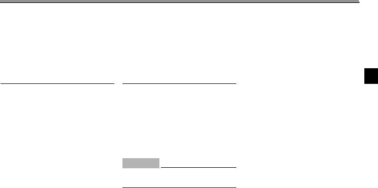
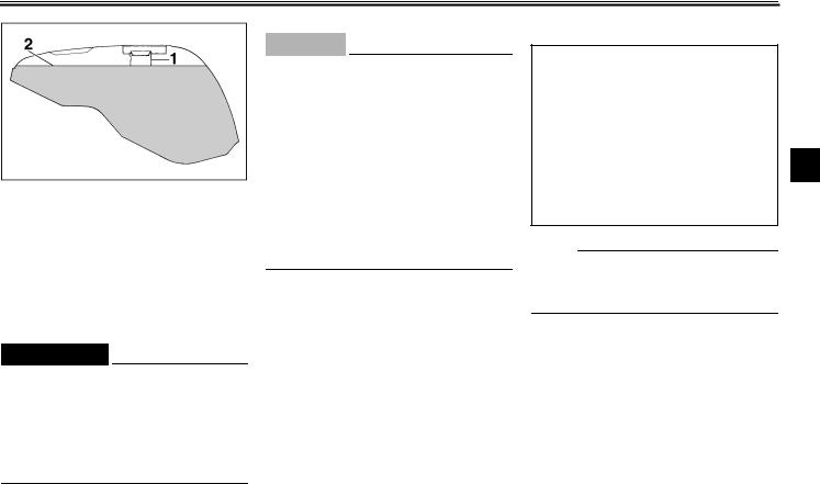
Left view
2
|
1. Starter (choke) “ |
” |
(page 3-13) |
8. Rear shock absorber compression |
||
|
2. Air filter |
(page 6-12) |
damping force adjusting screw |
(page 3-17) |
||
|
3. Fuse box |
(page 6-28) |
9. Main fuse |
(page 6-28) |
||
|
4. Helmet holder |
(page 3-14) |
10. Shift pedal |
(page 3-10) |
||
|
5. Rider seat lock |
(page 3-13) |
11. Front fork compression damping force |
|||
|
6. Storage compartment |
(page 3-15) |
adjusting screw |
(page 3-16) |
||
|
7. Tool kit |
(page 6-1) |
2-1

DESCRIPTION
Right view
2
|
12. Tail/brake light |
(page 6-30) |
19. Front fork rebound damping force |
|
|
13. Passenger seat |
(page 3-14) |
adjusting screw |
(page 3-16) |
|
14. Coolant reservoir tank |
(page 6-11) |
20. Headlight |
(page 6-29) |
|
15. Rider seat |
(page 3-13) |
21. Rear brake pedal |
(page 3-11) |
|
16. Rear shock absorber spring preload |
22. Rear shock absorber rebound damping |
||
|
adjusting ring |
(page 3-17) |
force adjusting knob |
(page 3-18) |
|
17. Fuel tank |
(page 3-11) |
23. Rear brake fluid level check window |
|
|
18. Front fork spring preload adjusting bolt |
(page 3-15) |
2-2

DESCRIPTION
Controls/Instruments
2
|
24. Clutch lever |
(page 3-9) |
|
25. Left handlebar switches |
(page 3-8) |
|
26. Speedometer |
(page 3-6) |
|
27. Main switch/steering lock |
(page 3-1) |
|
28. Tachometer |
(page 3-6) |
|
29. Coolant temperature gauge |
(page 3-7) |
|
30. Right handlebar switches |
(page 3-9) |
|
31. Throttle grip |
(page 6-15) |
|
32. Front brake lever |
(page 3-10) |
2-3
INSTRUMENT AND CONTROL FUNCTIONS
|
Main switch/steering lock……………………………….. |
3-1 |
|
Indicator lights ……………………………………………… |
3-2 |
|
Oil level indicator circuit check………………………… |
3-3 |
|
Fuel indicator circuit check …………………………….. |
3-5 |
|
Speedometer ……………………………………………….. |
3-6 |
|
Tachometer ………………………………………………….. |
3-6 |
|
Diagnosis device…………………………………………… |
3-7 |
|
Coolant temperature gauge ……………………………. |
3-7 |
|
Handlebar switches ………………………………………. |
3-8 |
|
Clutch lever ………………………………………………….. |
3-9 |
|
Shift pedal………………………………………………….. |
3-10 |
|
Front brake lever …………………………………………. |
3-10 |
|
Rear brake pedal ………………………………………… |
3-11 |
|
Fuel tank cap …………………………………………….. |
3-11 |
||||
|
Fuel ………………………………………………………….. |
3-12 |
||||
|
Fuel tank breather hose (for Germany only) …… |
3-13 |
||||
|
Starter (choke) “ |
” |
3-13 |
|||
|
Seats………………………………………………………… |
3-13 |
||||
|
Helmet holder |
3-14 |
||||
|
3 |
|||||
|
Storage compartment |
3-15 |
||||
|
…………………………………..Front fork adjustment |
3-15 |
||||
|
Rear shock absorber adjustment ………………….. |
3-17 |
||||
|
Luggage strap holders ………………………………… |
3-19 |
||||
|
EXUP (EXhaust Ultimate Powervalve)…………… |
3-19 |
||||
|
Sidestand ………………………………………………….. |
3-19 |
||||
|
Sidestand/clutch switch operation check………… |
3-20 |
|
INSTRUMENT AND CONTROL FUNCTIONS |
EAU00027 |
3
1. Push
2. Turn
Main switch/steering lock
The main switch controls the ignition and lighting systems. Its operation is described below.
EAU00036
ON
Electrical circuits are switched on. The engine can be started. The key cannot be removed in this position.
EAU00038
OFF
All electrical circuits are switched off. The key can be removed in this position.
LOCK
The steering is locked in this position and all electrical circuits are switched off. The key can be removed in this position.
To lock the steering, turn the handlebars all the way to the left. While pushing the key into the main switch, turn it from “OFF” to “LOCK” and remove it.
To release the lock, turn the key to “OFF” while pushing.
EW000016
 WARNING
Never turn the key to “OFF” or “LOCK” when the motorcycle is moving. The electrical circuits will be switched off which may result in loss of control or an accident. Be sure the motorcycle is stopped before turning the key to “OFF” or “LOCK”.
3-1

INSTRUMENT AND CONTROL FUNCTIONS
EAU00048
P (Parking)
The steering is locked in this position, and the taillight and auxiliary light come on but all other circuits are off. The key can be removed in this position.
To use the parking position, first lock the steering, then turn the key to “P”. Do not use this position for an extended length of time as the battery may discharge.
1.Neutral indicator light “  ”
”
2.Oil level indicator light “ 

 ”
”
3.Fuel indicator light “  ”
”
4.Turn indicator light “  ”
”
5.High beam indicator light “  ”
”
EAU00063
High beam indicator light “  ”
”
This indicator comes on when the headlight high beam is used.
EAU01313
Oil level indicator light “ 

 ”
”
This indicator comes on when the oil level is low. This light circuit can be 3 checked by the procedure on page 3-3.
EC000000
CAUTION:
Do not run the motorcycle until you know it has sufficient engine oil.
EAU00056
Indicator lights
EAU00057
Turn indicator light “  ”
”
This indicator flashes when the turn switch is moved to the left or right.
EAU00061
Neutral indicator light “  ”
”
This indicator comes on when the transmission is in neutral.
NOTE:
Even if the oil is filled to the specified level, the indicator light may flicker when riding on a slope or during sudden acceleration or deceleration, but this is normal.
3-2
INSTRUMENT AND CONTROL FUNCTIONS
EAU00071
Oil level indicator circuit check
|
Turn the main switch to “ON” and |
||||||||||||||||||||||||||||||||
|
the engine stop switch to “ |
”. |
|||||||||||||||||||||||||||||||
|
Oil level indicator light |
Oil level indicator light |
|||||||||||||||||||||||||||||||
|
3 |
||||||||||||||||||||||||||||||||
|
does not come on. |
comes on. |
|||||||||||||||||||||||||||||||
|
Put the transmission in neutral or |
Check engine oil level. |
|||||||||||||||||||||||||||||||
|
apply the clutch lever, then push |
||||||||||||||||||||||||||||||||
|
the start switch. |
||||||||||||||||||||||||||||||||
|
Oil level indicator light |
Oil level indicator light |
Oil level |
Oil level |
|||||||||||||||||||||||||||||
|
comes on. |
does not come on. |
is OK. |
is low. |
|||||||||||||||||||||||||||||
|
Engine oil level and |
Ask a Yamaha dealer to |
Supply |
||||||||||||||||||||||||||||||
|
electrical circuit are OK. |
inspect electrical circuit. |
engine oil. |
||||||||||||||||||||||||||||||
|
Go ahead with riding. |
||||||||||||||||||||||||||||||||
3-3
INSTRUMENT AND CONTROL FUNCTIONS
EAU01154
Fuel indicator light “  ”
”
When the fuel level drops below approximately 4.5 L, this light will come on. When this light comes on, fill the tank at the first opportunity. This light circuit can be checked by the proce-
dure on page 3-5.
3
3-4

INSTRUMENT AND CONTROL FUNCTIONS
EAU00085
Fuel indicator circuit check
|
Turn the main switch to “ON” and the |
||||||||||||||||||||||||||||||||
|
engine stop switch to “ |
”. |
|||||||||||||||||||||||||||||||
|
Fuel indicator light does |
Fuel indicator light |
|||||||||||||||||||||||||||||||
|
3 |
||||||||||||||||||||||||||||||||
|
not come on. |
comes on. |
|||||||||||||||||||||||||||||||
|
Put the transmission in neutral or |
Check the fuel level. |
|||||||||||||||||||||||||||||||
|
apply the clutch lever, then push |
||||||||||||||||||||||||||||||||
|
the start switch. |
||||||||||||||||||||||||||||||||
|
Fuel indicator light |
Fuel indicator light |
Fuel level |
Fuel level |
|||||||||||||||||||||||||||||
|
comes on. |
does not come on. |
is OK. |
is low. |
|||||||||||||||||||||||||||||
|
Fuel level and electrical |
Ask a Yamaha dealer to |
Supply fuel. |
||||||||||||||||||||||||||||||
|
circuit are OK. |
inspect electrical circuit. |
|||||||||||||||||||||||||||||||
|
Go ahead with riding. |
||||||||||||||||||||||||||||||||
3-5
INSTRUMENT AND CONTROL FUNCTIONS
1.Speedometer
2.Odometer
3.Trip odometer
4.Reset knob
EAU00095
Speedometer
The speedometer shows riding speed. This speedometer is equipped with an odometer and trip odometer. The trip odometer can be reset to “0” with the reset knob. Use the trip odometer to estimate how far you can ride on a tank of fuel. This information will enable you to plan fuel stops in the future.
3
1.Tachometer
2.Red zone
EAU00101
Tachometer
This model is equipped with an electric tachometer so the rider can monitor the engine speed and keep it within the ideal power range.
EC000003
CAUTION:
Do not operate in the red zone.
Red zone: 11,500 r/min and above
3-6
![]()
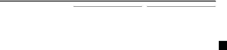
INSTRUMENT AND CONTROL FUNCTIONS
EAU00106
Diagnosis device
This model is equipped with a self diagnosis for the following circuits.
● Throttle Position Sensor (T.P.S.) circuit
● Exhaust Ultimate Power valve
3
(EXUP) circuit
● Fuel level indicator circuit
If some trouble should occur in any of these circuits, the tachometer will repeatedly display as follows:
|
0 r/min for |
Specified r/min |
Current |
|
|
for the faulty |
engine |
||
|
3 seconds |
|||
|
circuit for |
r/min for |
||
|
2.5 seconds |
3 seconds |
||
|
(see chart below) |
Use this chart to identify what circuit is faulty according to the specified r/min displayed.
Specified
Faulty circuit
r/min
3,000 r/min
Throttle Position Sensor (T.P.S.)
7,000 r/min
Exhaust Ultimate Power valve (EXUP)
8,000 r/min Fuel level indicator
If the tachometer displays as described above, take note of the specified r/min and then take your motorcycle to a Yamaha dealer for repair.
EC000004
CAUTION:
To prevent engine damage, be sure to consult a Yamaha dealer as soon as possible if the tachometer displays a repeated change in r/min.
1.Coolant temperature gauge
2.Red zone
EAU01652
Coolant temperature gauge
This gauge indicates the coolant temperature when the main switch is on. The engine operating temperature will vary with changes in weather and engine load. If the needle points to the red zone or higher, stop your motorcycle and let the engine cool. (See page 6-11 for details.)
EC000002
CAUTION:
When the engine is overheated, do not continue riding.
3-7

INSTRUMENT AND CONTROL FUNCTIONS
1.Pass switch “PASS”
2.Dimmer switch
3.Turn signal switch
4.Horn switch “  ”
”
EAU00127
Turn signal switch
To signal a right-hand turn, push the switch to “  ”. To signal a left-hand turn, push the switch to “
  ”. Once the switch is released it will return to the center position. To cancel the signal, push the switch in after it has returned
|
to the center position. |
3 |
|
EAU00130 |
|
|
Horn switch “ ” |
|
|
Press the switch to sound the horn. |
EAU00118
Handlebar switches
EAU00120
Pass switch “PASS”
Press the switch to operate the passing light.
EAU00121
Dimmer switch
Turn the switch to “  ” for the high beam and to “
  ” for the low beam.
3-8

INSTRUMENT AND CONTROL FUNCTIONS
3
1.Engine stop switch
2.Lights switch
3.Start switch “  ”
”
EAU00134
Lights switch
Turning the light switch to “  ”, turns on the auxiliary light, meter lights and taillight. Turning the light switch to “
  ” turns the headlight on also.
EAU00138
Engine stop switch
The engine stop switch is a safety device for use in an emergency such as when the motorcycle overturns or if trouble occurs in the throttle system. Turn the switch to “  ” to start the engine. In case of emergency, turn the switch to “
  ” to stop the engine.
EAU00141
Start switch “  ”
”
The starter motor cranks the engine when pushing the start switch.
EC000005
CAUTION:
See starting instructions prior to starting the engine.
1. Lever position adjusting dial
2. Arrow mark
a. Lever distance
EAU00153
Clutch lever
The clutch lever is located on the left handlebar. It is equipped with a clutch lever adjusting dial and a clutch switch, which is integrated into the ignition circuit cut-off system. (Refer to the engine starting procedures for a description of this system.)
To disengage the clutch, pull the clutch lever toward the handlebar. To engage the clutch, release the lever. The lever should be pulled rapidly and released slowly for smooth clutch operation.
3-9
INSTRUMENT AND CONTROL FUNCTIONS
To adjust the distance between the clutch lever and the handlebar grip, turn the clutch adjusting dial while pushing the lever forward. Make sure the setting on the clutch lever adjusting dial is aligned with the arrow mark.
1. Shift pedal
EAU00157
Shift pedal
This motorcycle is equipped with a con- stant-mesh 5-speed transmission. The shift pedal is located on the left side of the engine and is used in combination with the clutch when shifting.
3
1.Lever position adjusting dial
2.Arrow mark
a. Lever distance
EAU00161
Front brake lever
The front brake lever is located on the right handlebar and is equipped with a brake lever adjusting dial. To activate the front brake, pull the lever toward the handlebar.
To adjust the front brake lever position, turn the brake lever adjusting dial while pulling the lever forward. Make sure the setting on the brake lever adjusting dial is aligned with the arrow mark.
3-10
INSTRUMENT AND CONTROL FUNCTIONS
3
1. Rear brake pedal
EAU00162
Rear brake pedal
The rear brake pedal is on the right side of the motorcycle. Press down on the brake pedal to apply the rear brake.
1.Lock cover
2.Open
EAU02935
Fuel tank cap
To open
Open the lock cover. Insert the key and turn it 1/4 turn clockwise. The lock will be released and the cap can be opened.
To close
Push the tank cap into position with the key inserted. To remove the key, turn it counterclockwise to the original position. Then, close the lock cover.
NOTE:
This tank cap cannot be closed unless the key is in the lock. The key cannot be removed if the cap is not locked properly.
EW000023
 WARNING
Be sure the cap is properly installed and locked in place before riding the motorcycle.
3-11
INSTRUMENT AND CONTROL FUNCTIONS
1.Filler tube
2.Fuel level
EAU01183
Fuel
Make sure there is sufficient fuel in the tank. Fill the fuel tank to the bottom of the filler tube as shown in the illustration.
EW000130
 WARNING
Do not overfill the fuel tank. Avoid spilling fuel on the hot engine. Do not fill the fuel tank above the bottom of the filler tube or it may overflow when the fuel heats up later and expands.
EAU00186
CAUTION:
●Always wipe off spilled fuel immediately with a dry and clean soft cloth. Fuel may deteriorate painted surfaces or plastic parts.
●(For Germany only)
The fuel tank cap equipped on German models is specially designed. Always use the correct cap whenever replacement is necessary.
EAU00191
Recommended fuel:
Regular unleaded gasoline with a research octane number of 91 or higher.
Fuel tank capacity:
Total:
20 L 3 Reserve:
4.5 L
NOTE:
If knocking or pinging occurs, use a different brand of gasoline or higher octane grade.
3-12

INSTRUMENT AND CONTROL FUNCTIONS
3
1. Fuel tank breather hose
EAU00196
Fuel tank breather hose (for Germany only)
This model is equipped with a fuel tank breather hose. Before using this motorcycle, be sure to:
●Check hose connection.
●Check hose for cracks or damage. Replace if damaged.
●Make sure the end of the hose is not blocked. Clean it if necessary.
|
1. Starter (choke) “ |
” |
1. Rider seat lock |
||||||
|
EAU02976 |
EAU01698* |
|||||||
|
Starter (choke) “ |
” |
Seats |
||||||
|
Starting a cold engine requires a richer |
Rider seat |
|||||||
|
air-fuel mixture. A separate starter cir- |
To remove |
|||||||
|
cuit supplies this mixture. |
Insert the key into the seat lock and |
|||||||
|
Move in direction a to turn on the |
turn it as shown. |
|||||||
|
starter (choke). |
||||||||
|
Move in direction b to turn off the |
||||||||
|
starter (choke). |
3-13
INSTRUMENT AND CONTROL FUNCTIONS
1.Projection
2.Seat holder
To install
Insert the projection on the front of the seat into the holder on the frame. Then push down on the seat.
1.Projection
2.Hook (× 2)
3.Seat holder (× 3)
Passenger seat
To remove
Remove the rider seat. Then pull upward on the passenger seat.
To install
Insert the projection on the rear of the seat and the hooks on the front of the seat into the holders on the frame, and push the seat backward. Then install the rider seat.
NOTE:
Make sure that the seats are securely fitted.
3
1. Helmet holder
EAU00264
Helmet holder
The helmet holder is located under the rider’s seat. Remove the rider’s seat and hook the helmet on the helmet holder. Then lock the seat.
EW000030
 WARNING
Never ride with a helmet in the helmet holder. The helmet may hit objects, causing loss of control and possibly an accident.
3-14

INSTRUMENT AND CONTROL FUNCTIONS
3
1. U-LOCK
EAU01688
Storage compartment
This compartment is designed to store a genuine Yamaha U-LOCK. (Other locks may not fit.) Be sure the lock is fastened securely with the straps when storing it in the compartment.
To prevent losing the straps, be sure to secure them even when a U-LOCK is not being stored in the compartment.
When storing this Owner’s manual or other documents in the compartment, be sure to put them in a vinyl bag so they do not get wet. When washing the motorcycle, be careful not to flood this compartment with water.
1. Spring preload adjusting bolt
EAU01862*
Front fork adjustment
This front fork is equipped with spring preload and damping force adjusters.
EW000037
 WARNING
Each fork leg must be set to the same pressure. Uneven setting can cause poor handling and loss of stability.
1.Setting
2.Front fork cap bolt
Adjusting spring preload
Turn the adjusting bolt in direction a to increase spring preload and in direction b to decrease spring preload. Align the preferred setting with the top of the front fork cap bolt.
3-15
INSTRUMENT AND CONTROL FUNCTIONS
EC000013
CAUTION:
The grooves are provided to show the adjustment level. Always keep the adjustment level equal on both fork legs.
|
Hard |
Stan- |
Soft |
||||
|
dard |
||||||
|
Adjusting |
1 |
2 |
3 |
4 |
5 |
|
|
position |
||||||
1. Rebound damping force adjusting screw
Adjusting rebound damping force
Turn the adjusting screw in direction a to increase rebound damping force and in direction b to decrease rebound damping force.
|
Minimum (soft) |
25 clicks out* |
|
Standard |
9 clicks out* |
|
Maximum (hard) |
0 clicks out* |
* From the fully turned-in position
3
1. Compression damping force adjusting screw
Adjusting compression damping force
Turn the adjusting screw in direction a to increase compression damping force and in direction b to decrease compression damping force.
|
Minimum (soft) |
25 clicks out* |
|
Standard |
12 clicks out* |
|
Maximum (hard) |
0 clicks out* |
* From the fully turned-in position
3-16
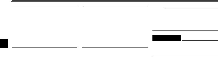
![]()
INSTRUMENT AND CONTROL FUNCTIONS
EC000015
CAUTION:
Never attempt to turn an adjuster beyond the maximum or minimum setting.
NOTE:
3Although the number of clicks between the minimum and maximum settings
may vary with each individual shock absorber and may not exactly match these specifications, it is always the full damping force range that extends over the actual number of clicks.
1.Spring preload adjusting ring
2.Position indicator
EAU01592*
Rear shock absorber adjustment
This shock absorber is equipped with spring preload and damping force adjusters.
EC000015
CAUTION:
Never attempt to turn an adjuster beyond the maximum or minimum setting.
Adjusting spring preload
Turn the adjusting ring in direction a to increase spring preload and in direction b to decrease spring preload.
Make sure that the appropriate notch in the adjusting ring is aligned with the position indicator on the rear shock absorber.
|
Soft |
Stan- |
Hard |
|||||||||
|
dard |
|||||||||||
|
Adjusting |
1 |
2 |
3 |
4 |
5 |
6 |
7 |
8 |
9 |
||
|
position |
3-17
 Loading…