- Manuals
- Brands
- Yamaha Manuals
- Motorcycle
- XVS950CU
- Owner’s manual
-
Contents
-
Table of Contents
-
Troubleshooting
-
Bookmarks
Quick Links
Read this manual carefully before operating this vehicle.
OWNER’S MANUAL
XVS950CU
2DX-28199-E0
Related Manuals for Yamaha XVS950CU
Summary of Contents for Yamaha XVS950CU
-
Page 1
Read this manual carefully before operating this vehicle. OWNER’S MANUAL XVS950CU 2DX-28199-E0… -
Page 2
Read this manual carefully before operating this vehicle. This manual should stay with this vehicle if it is sold. YAMAHA MOTOR ELECTRONICS CO., LTD. 1450-6, Mori, Mori-machi, Shuchi-gun, Shizuoka-ken, 437-0292 Japan DECLARATION of CONFORMITY Company: YAMAHA MOTOR ELECTRONICS CO., LTD. Address: 1450-6, Mori, Mori-Machi, Shuchi-gun, Shizuoka-Ken, 437-0292 Japan Hereby declare that the product: Kind of equipment: IMMOBILIZER… -
Page 3
Yamaha a reputation for dependability. Please take the time to read this manual thoroughly, so as to enjoy all advantages of your XVS950CU. The Owner’s Manual does not only instruct you in how to operate, inspect and maintain your motorcycle, but also in how to safeguard yourself and others from trouble and injury. -
Page 4: Important Manual Information
IMPORTANT MANUAL INFORMATION EAU10133 Particularly important information is distinguished in this manual by the following notations: This is the safety alert symbol. It is used to alert you to potential personal injury hazards. Obey all safety messages that follow this symbol to avoid possible injury or death.
-
Page 5
IMPORTANT MANUAL INFORMATION EAU10200 XVS950CU OWNER’S MANUAL ©2013 by Yamaha Motor Co., Ltd. 1st edition, May 2013 All rights reserved. Any reprinting or unauthorized use without the written permission of Yamaha Motor Co., Ltd. is expressly prohibited. Printed in Japan. -
Page 6: Table Of Contents
TABLE OF CONTENTS SAFETY INFORMATION ….1-1 FOR YOUR SAFETY – Checking the brake lever free PRE-OPERATION CHECKS ….. 4-1 play ……….. 6-17 DESCRIPTION ……..2-1 Brake light switches ….. 6-18 Left view ……….2-1 OPERATION AND IMPORTANT Checking the front and rear brake Right view ……..2-2 RIDING POINTS………
-
Page 7
TABLE OF CONTENTS Replacing the auxiliary light bulb ………..6-30 Supporting the motorcycle ….6-31 Troubleshooting ……6-32 Troubleshooting chart ….6-33 MOTORCYCLE CARE AND STORAGE ……….7-1 Matte color caution ……7-1 Care ……….7-1 Storage ………..7-3 SPECIFICATIONS ……8-1 CONSUMER INFORMATION…..9-1 Identification numbers ….9-1… -
Page 8: Safety Information
SAFETY INFORMATION ● EAU1028A Never operate a motorcycle with- yourself conspicuous appears to out proper training or instruction. be very effective in reducing the Take a training course. Beginners chance of this type of accident. Be a Responsible Owner should receive training from a cer- Therefore: As the vehicle’s owner, you are respon- tified instructor.
-
Page 9
SAFETY INFORMATION ● Many accidents involve inexperi- • Always signal before turning or Protective Apparel enced operators. In fact, many op- changing lanes. Make sure that The majority of fatalities from motorcy- erators who have been involved in other motorists can see you. cle accidents are the result of head in- accidents do not even have a cur- ●… -
Page 10
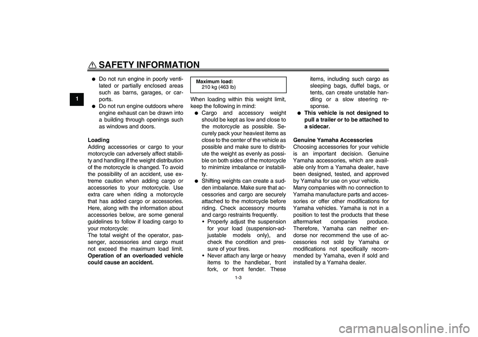
SAFETY INFORMATION ● Avoid Carbon Monoxide Poisoning Do not run engine outdoors where When loading within this weight limit, All engine exhaust contains carbon engine exhaust can be drawn into keep the following in mind: monoxide, a deadly gas. Breathing car- a building through openings such ●… -
Page 11
Yamaha accessories, which are avail- formed to your vehicle that change any lightweight as possible and able only from a Yamaha dealer, have of the vehicle’s design or operation should be kept to a minimum. been designed, tested, and approved characteristics can put you and others •… -
Page 12: Specifications
SAFETY INFORMATION ● tor and may limit control ability, Check that the fuel cock (if therefore, such accessories are equipped) is in the “OFF” position not recommended. and that there are no fuel leaks. ● Use caution when adding electri- ●…
-
Page 13: Description
DESCRIPTION EAU10410 Left view 4,5,6 1. Headlight (page 6-28) 9. Engine oil filler cap (page 6-10) 2. Owner’s tool kit (page 6-2) 3. Shock absorber assembly spring preload adjusting ring (page 3-17) 4. Main fuse (page 6-26) 5. Fuse box (page 6-26) 6.
-
Page 14: Right View
DESCRIPTION EAU10420 Right view 1. License plate light (page 6-30) 9. Engine oil filter cartridge (page 6-10) 2. Tail/brake light (page 6-29) 10.Brake pedal (page 3-11) 3. Battery (page 6-25) 4. Rear brake fluid reservoir (page 6-19) 5. Air filter element (page 6-13) 6.
-
Page 15: Controls And Instruments
DESCRIPTION EAU10430 Controls and instruments 1. Clutch lever (page 3-10) 2. Left handlebar switches (page 3-8) 3. Multi-function meter unit (page 3-5) 4. Front brake fluid reservoir (page 6-19) 5. Right handlebar switches (page 3-8) 6. Brake lever (page 3-10) 7.
-
Page 16: Instrument And Control Functions
● the vehicle along with all three keys to Do not expose any key to exces- a Yamaha dealer to have them re-reg- sively high temperatures. istered. Do not use the key with the red ● Do not place any key close to bow for driving.
-
Page 17: Main Switch
INSTRUMENT AND CONTROL FUNCTIONS ● Keep other immobilizer system EAU56200 Main switch keys away from the main switch Be sure to use the standard key (black as they may cause signal inter- bow) for regular use of the vehicle. To ference.
-
Page 18: Indicator Lights And Warning Lights
7. Neutral indicator light “ ” 8. High beam indicator light “ ” or if the warning light remains on, have a Yamaha dealer check the electrical EAU11020 circuit. Turn signal indicator light “ ” This indicator light flashes when the turn signal switch is pushed to the left or ●…
-
Page 19
3.0 seconds. If this oc- light comes on when the key is turned have a Yamaha dealer check the curs, have a Yamaha dealer check the to “ON”, and goes off after traveling at a vehicle. -
Page 20: Multi-Function Meter Unit
If the indicator light does not come on equipped with the following: initially when the key is turned to “ON”, ● a speedometer or if the indicator light remains on, have ● an odometer a Yamaha dealer check the electrical circuit.
-
Page 21
INSTRUMENT AND CONTROL FUNCTIONS ● two tripmeters (which show the Push the “SELECT” switch to switch distance traveled since they were the display between the odometer last set to zero) mode “ODO”, the tripmeter modes ● a fuel reserve tripmeter (which “TRIP 1”and “TRIP 2”… -
Page 22
2. If the engine starts, turn it off and note the code number, and then have a 5. Push the “RESET” switch for at try starting the engine with the Yamaha dealer check the vehicle. least two seconds to start the standard keys. The self-diagnosis device also detects clock. -
Page 23: Handlebar Switches
INSTRUMENT AND CONTROL FUNCTIONS key and both standard keys to a EAU1234C Right Handlebar switches Yamaha dealer and have the stan- dard keys re-registered. Left ECA11590 NOTICE If the display indicates an error code, the vehicle should be checked as soon as possible in order to avoid engine damage.
-
Page 24
INSTRUMENT AND CONTROL FUNCTIONS position. To cancel the turn signal EAU12733 EAU55710 Hazard switch “ ” “RESET” switch lights, push the switch in after it has re- With the key in the “ON” or “ ” posi- This switch is used to reset the tripme- turned to the center position. -
Page 25: Clutch Lever
INSTRUMENT AND CONTROL FUNCTIONS EAU12820 EAU12871 EAU12891 Clutch lever Shift pedal Brake lever 1. Clutch lever 1. Shift pedal 1. Brake lever 2. Neutral position The clutch lever is located at the left The brake lever is located on the right The shift pedal is located on the left handlebar grip.
-
Page 26: Brake Pedal
EAU51670 Brake pedal ● The ABS performs a self-diagno- The Yamaha ABS (Anti-lock Brake sis test each time the vehicle first System) features a dual electronic con- starts off after the key is turned to trol system, which acts on the front and “ON”…
-
Page 27: Fuel Tank Cap
INSTRUMENT AND CONTROL FUNCTIONS wheel hubs may be damaged, result- EAU13122 2. Turn the key counterclockwise to Fuel tank cap ing in improper performance of the the original position, remove it, and ABS system. then close the lock cover. The fuel tank cap cannot be installed unless the key is in the lock.
-
Page 28: Fuel
Gasoline is poisonous and can hole. Stop filling when the fuel Your Yamaha engine has been de- cause injury or death. Handle gaso- reaches the bottom of the filler signed to use regular unleaded gaso- line with care.
-
Page 29: Fuel Tank Breather/Overflow Hose
Do not park the vehicle near ohol containing methanol possible fire hazards such as recommended by Yamaha because it grass or other materials that can cause damage to the fuel system easily burn. or vehicle performance problems. 1. Fuel tank breather/overflow hose ●…
-
Page 30: Steering Lock
INSTRUMENT AND CONTROL FUNCTIONS ECA10701 EAU55660 To unlock the steering Steering lock NOTICE Use only unleaded gasoline. The use of leaded gasoline will cause unre- pairable damage to the catalytic converter. 1. Unlock. 1. Steering lock 1. Insert the key into the steering 2.
-
Page 31: Rider Seat
INSTRUMENT AND CONTROL FUNCTIONS EAU55820 4. Install the panel. Rider seat Make sure that the rider seat is properly To remove the rider seat secured before riding. 1. Remove panel A. (See page 6-8.) 2. Remove the bolt. 1. Projection 2.
-
Page 32: Adjusting The Shock Absorber Assemblies
Take the shock Maximum (hard): maximum or minimum settings. 4 notch(es) in direction (a)* absorber assembly to a Yamaha Adjust the spring preload as follows. * With the adjusting ring fully turned in dealer for any service. direction (b)
-
Page 33: Sidestand
EAU44892 Sidestand Ignition circuit cut-off system Yamaha dealer repair it if it does not The sidestand is located on the left side The ignition circuit cut-off system (com- function properly. of the frame. Raise the sidestand or…
-
Page 34
INSTRUMENT AND CONTROL FUNCTIONS WARNING With the engine turned off: 1. Move the sidestand down. If a malfunction is noted, have a Yamaha 2. Make sure that the engine stop switch is set to “ ”. dealer check the system before riding. -
Page 35: For Your Safety — Pre-Operation Checks
• If necessary, add recommended oil to specified level. 6-10 • Check vehicle for oil leakage. • Check operation. • If soft or spongy, have Yamaha dealer bleed hydraulic system. • Check brake pads for wear. Front brake • Replace if necessary.
-
Page 36
• Make sure that operation is smooth. • Check throttle grip free play. Throttle grip 6-13, 6-21 • If necessary, have Yamaha dealer adjust throttle grip free play and lubricate cable and grip housing. • Make sure that operation is smooth. Control cables 6-21 •… -
Page 37
FOR YOUR SAFETY – PRE-OPERATION CHECKS ITEM CHECKS PAGE • Check operation of ignition circuit cut-off system. Sidestand switch 3-18 • If system is not working correctly, have Yamaha dealer check vehicle. -
Page 38: Operation And Important Riding Points
● a lean angle sensor to stop the en- understand, ask your Yamaha dealer. ● The transmission is in the neutral gine in case of a turnover. In this EWA10271 position.
-
Page 39: Shifting
The neutral indicator etc. light should come on. If not, ask a The gear positions are shown in the il- Yamaha dealer to check the elec- lustration. trical circuit. 3. Start the engine by pushing the To shift the transmission into the neu- start switch.
-
Page 40: Tips For Reducing Fuel Consumption
OPERATION AND IMPORTANT RIDING POINTS ECA10260 EAU16810 EAU16841 Tips for reducing fuel con- Engine break-in NOTICE sumption There is never a more important period ● Even with the transmission in in the life of your engine than the period Fuel consumption depends largely on the neutral position, do not between 0 and 1600 km (1000 mi).
-
Page 41: Parking
If any engine trouble should occur WARNING during the engine break-in period, ● Since the engine and exhaust immediately have a Yamaha dealer system can become very hot, check the vehicle. park in a place where pedestri- ans or children are not likely to touch them and be burned.
-
Page 42: Periodic Maintenance And Adjustment
– possibly leading to pending on the weather, terrain, geo- that is certified (if applicable). Yamaha death. See page 1-3 for more in- graphical location, and individual use, dealers are trained and equipped to…
-
Page 43: Owner’s Tool Kit
Owner’s tool kit ● If you do not have the tools or ex- perience required for a particular job, have a Yamaha dealer per- form it for you. ● Install the owner’s tool box with the “INSIDE” mark facing inward.
-
Page 44: Periodic Maintenance Chart For The Emission Control System
● From 50000 km (30000 mi), repeat the maintenance intervals starting from 10000 km (6000 mi). ● Items marked with an asterisk should be performed by a Yamaha dealer as they require special tools, data and technical skills. EAU46910 Periodic maintenance chart for the emission control system…
-
Page 45: General Maintenance And Lubrication Chart
PERIODIC MAINTENANCE AND ADJUSTMENT EAU1770F General maintenance and lubrication chart ODOMETER READING ANNUAL ITEM CHECK OR MAINTENANCE JOB 1000 km 10000 km 20000 km 30000 km 40000 km CHECK (600 mi) (6000 mi) (12000 mi) (18000 mi) (24000 mi) √ Air filter element •…
-
Page 46
PERIODIC MAINTENANCE AND ADJUSTMENT ODOMETER READING ANNUAL ITEM CHECK OR MAINTENANCE JOB 1000 km 10000 km 20000 km 30000 km 40000 km CHECK (600 mi) (6000 mi) (12000 mi) (18000 mi) (24000 mi) • Check operation and for exces- √ √… -
Page 47
PERIODIC MAINTENANCE AND ADJUSTMENT ODOMETER READING ANNUAL ITEM CHECK OR MAINTENANCE JOB 1000 km 10000 km 20000 km 30000 km 40000 km CHECK (600 mi) (6000 mi) (12000 mi) (18000 mi) (24000 mi) • Check operation and for oil leak- √… -
Page 48
PERIODIC MAINTENANCE AND ADJUSTMENT ● Hydraulic brake service • Regularly check and, if necessary, correct the brake fluid level. • Every two years replace the internal components of the brake master cylinders and calipers, and change the brake fluid. • Replace the brake hoses every four years and if cracked or damaged. -
Page 49: Removing And Installing The Panel
PERIODIC MAINTENANCE AND ADJUSTMENT EAU18751 EAU42432 Removing and installing the Checking the spark plugs panel The spark plugs are important engine components, which are easy to check. The panel shown needs to be removed Since heat and deposits will cause any to perform some of the maintenance spark plug to slowly erode, the spark jobs described in this chapter.
-
Page 50
3. Remove the spark plug as shown, 0.8–0.9 mm (0.031–0.035 in) diagnose such problems yourself. In- with the spark plug wrench includ- stead, have a Yamaha dealer check ed in the additional tool kit, which the vehicle. was handed out separately at the… -
Page 51: Engine Oil And Oil Filter Cartridge
PERIODIC MAINTENANCE AND ADJUSTMENT To install a spark plug EAU47112 Engine oil and oil filter car- 1. Clean the surface of the spark plug The engine oil should be between the tridge gasket and its mating surface, and minimum and maximum level marks. The engine oil level should be checked then wipe off any grime from the before each ride.
-
Page 52: To Change Engine Oil
An oil filter wrench is available at a oil of the recommended type to Yamaha dealer. raise it to the correct level. 5. Apply a thin coat of clean engine 6. Insert the dipstick into the oil filler…
-
Page 53
17 Nm (1.7 m·kgf, 12 ft·lbf) correct, immediately turn the engine ● In order to prevent clutch slip- off and have a Yamaha dealer check 7. Install the engine oil drain bolt and page (since the engine oil also the vehicle. -
Page 54: Replacing The Air Filter Element
Periodi- be operated without the air filter cally check the throttle grip free play element installed, otherwise the and, if necessary, have a Yamaha deal- piston(s) and/or cylinder(s) may er adjust it. become excessively worn.
-
Page 55: Valve Clearance
Tire air pressure (measured on cold from occurring, the valve clearance small area of road contact. Therefore, it tires): must be adjusted by a Yamaha dealer is essential to maintain the tires in good 0–90 kg (0–198 lb): Front: at the intervals specified in the periodic condition at all times and replace them 225 kPa (2.25 kgf/cm², 33 psi)
-
Page 56
Yamaha dealer re- the vehicle may be different, which ● The replacement of all wheel place the tire immediately. -
Page 57: Cast Wheels
If any 4. Loosen the locknut at the crank- damage is found, have a Yamaha case. dealer replace the wheel. Do not attempt even the smallest repair to the wheel.
-
Page 58: Checking The Brake Lever Free Play
1. No brake lever free play There should be no free play at the brake lever end. If there is free play, have a Yamaha dealer inspect the brake system. EWA14211 WARNING A soft or spongy feeling in the brake lever can indicate the presence of air in the hydraulic system.
-
Page 59: Brake Light Switches
EAU22500 Rear brake pads fect. If necessary, have a Yamaha deal- ified in the periodic maintenance and er adjust the brake light switches. lubrication chart. EAU22430 Front brake pads 1.
-
Page 60: Checking The Brake Fluid Level
PERIODIC MAINTENANCE AND ADJUSTMENT ● EAU40261 Rear brake Use only the specified brake flu- Checking the brake fluid level id; otherwise, the rubber seals Before riding, check that the brake fluid may deteriorate, causing leak- is above the minimum level mark. age.
-
Page 61: Changing The Brake Fluid
EAU22732 EAU23040 Changing the brake fluid Drive belt slack Yamaha dealer check the cause before Have a Yamaha dealer change the The drive belt slack should be checked further riding. brake fluid at the intervals specified in…
-
Page 62: Checking And Lubricating The Cables
Yamaha dealer at the intervals speci- ed if necessary. If a cable is damaged fied in the periodic maintenance chart.
-
Page 63: Checking And Lubricating The Brake And Shift Pedals
PERIODIC MAINTENANCE AND ADJUSTMENT EAU44273 EAU23143 Recommended lubricant: Checking and lubricating the Checking and lubricating the Lithium-soap-based grease brake and shift pedals brake and clutch levers The operation of the brake and shift The operation of the brake and clutch pedals should be checked before each levers should be checked before each ride, and the pedal pivots should be lu-…
-
Page 64: Checking And Lubricating The Sidestand
The operation of the sidestand should The swingarm pivots must be lubricat- be checked before each ride, and the ed by a Yamaha dealer at the intervals sidestand pivot and metal-to-metal specified in the periodic maintenance contact surfaces should be lubricated if and lubrication chart.
-
Page 65: Checking The Front Fork
WARNING! To avoid injury, of it falling over. have a Yamaha dealer check or re- [EWA10751] securely support the vehicle so 2. Hold the lower ends of the front pair it.
-
Page 66: Checking The Wheel Bearings
WARNING To charge the battery ● Electrolyte is poisonous and Have a Yamaha dealer charge the bat- dangerous since it contains sul- tery as soon as possible if it seems to furic acid, which causes severe have discharged. Keep in mind that the burns.
-
Page 67: Replacing The Fuses
PERIODIC MAINTENANCE AND ADJUSTMENT battery tends to discharge more quickly is turned to “OFF”, then con- EAU56240 Replacing the fuses if the vehicle is equipped with optional nect the positive lead before The main fuse, the ABS motor fuse, electrical accessories. connecting the negative lead.
-
Page 68
4. If the fuse immediately blows ward. possibly a fire. again, have a Yamaha dealer [EWA15131] check the electrical system. 6-27… -
Page 69: Replacing The Headlight Bulb
PERIODIC MAINTENANCE AND ADJUSTMENT EAU48513 Replacing the headlight bulb This model is equipped with a halogen bulb headlight. If the headlight bulb burns out, replace it as follows. ECA10650 NOTICE Take care not to damage the follow- ing parts: ● Headlight bulb 1.
-
Page 70: Tail/Brake Light
2. Turn signal light lens 1. “TOP” mark 2. Remove the burnt-out bulb by pushing it in and turning it counter- 6. Install the headlight unit by install- clockwise. ing the screws. 7. Have a Yamaha dealer adjust the headlight beam if necessary. 6-29…
-
Page 71: License Plate Light
License plate light Replacing the auxiliary light If the license plate light does not come bulb on, have a Yamaha dealer check the If the auxiliary light bulb burns out, re- electrical circuit or replace the bulb. place it as follows.
-
Page 72: Supporting The Motorcycle
PERIODIC MAINTENANCE AND ADJUSTMENT EAU24350 a jack either under each side of the Supporting the motorcycle frame in front of the rear wheel or under Since this model is not equipped with a each side of the swingarm. centerstand, follow these precautions when removing the front and rear wheel or performing other maintenance requiring the motorcycle to stand up-…
-
Page 73: Troubleshooting
However, should your motorcycle require any repair, take it to a Yamaha dealer, whose skilled technicians have the necessary tools, experience, and know-how to service the motorcycle properly.
-
Page 74: Troubleshooting Chart
Remove the spark plugs and check the electrodes. The engine does not start. Have a Yamaha dealer check the vehicle. Check the compression. 4. Compression The engine does not start. There is compression.
-
Page 75: Motorcycle Care And Storage
Some models are equipped with ble. Rust and corrosion can develop matte colored finished parts. Be Cleaning sure to consult a Yamaha dealer for even if high-quality components are ECA10772 advice on what products to use be- used. A rusty exhaust pipe may go un-…
-
Page 76
MOTORCYCLE CARE AND STORAGE off any detergent residue using Test the product on a small hid- plenty of water, as it is harmful den part of the windshield to Salt sprayed on roads in the winter may to plastic parts. make sure that it does not leave remain well into spring. -
Page 77: Storage
Contaminants on the brakes or tires of the presence of ammonia) can cause loss of control. ● Consult a Yamaha dealer for ad- and areas where strong chemi- ● Make sure that there is no oil or vice on what products to use.
-
Page 78
MOTORCYCLE CARE AND STORAGE 2. Fill up the fuel tank and add fuel e. Remove the spark plug caps stabilizer (if available) to prevent from the spark plugs, and then Make any necessary repairs before the fuel tank from rusting and the install the spark plugs and the storing the motorcycle. -
Page 79: Specifications
SPECIFICATIONS Dimensions: Engine oil: Fuel reserve amount: 2.8 L (0.74 US gal, 0.62 Imp.gal) Overall length: Recommended brand: Fuel injection: 2290 mm (90.2 in) YAMALUBE Overall width: Type: Throttle body: 830 mm (32.7 in) SAE 10W-30, 10W-40, 10W-50, 15W-40, ID mark: Overall height: 20W-40 or 20W-50 1TP1 00…
-
Page 80
SPECIFICATIONS 5th: Rear: Front suspension: 1.042 (25/24) 250 kPa (2.50 kgf/cm², 36 psi) Type: Chassis: Loading condition: Telescopic fork 90–202 kg (198–445 lb) Frame type: Spring/shock absorber type: Front: Double cradle Coil spring/oil damper 250 kPa (2.50 kgf/cm², 36 psi) Caster angle: Wheel travel: Rear:… -
Page 81
SPECIFICATIONS Rear turn signal light: Parking lighting fuse: 12 V, 21.0 W × 2 15.0 A Auxiliary light: Fuel injection system fuse: 12 V, 5.0 W × 1 10.0 A License plate light: ABS control unit fuse: 12 V, 5.0 W × 1 7.5 A Meter lighting: ABS motor fuse:… -
Page 82: Consumer Information
Record the vehicle identification num- ber and model label information in the spaces provided below for assistance when ordering spare parts from a Yamaha dealer or for reference in case the vehicle is stolen. VEHICLE IDENTIFICATION NUMBER: 1. Vehicle identification number 1.
-
Page 83
INDEX Fuel …………3-13 Part locations ………. 2-1 Fuel consumption, tips for reducing ..5-3 Pass switch……….3-8 ABS …………3-11 Fuel level warning light……3-4 ABS warning light ……..3-4 Fuel tank breather/overflow hose..3-14 Air filter element, replacing ….6-13 RESET switch……… 3-9 Fuel tank cap………3-12 Auxiliary light bulb, replacing …. -
Page 84
INDEX Turn signal switch ……..3-8 Valve clearance ……..6-14 Vehicle identification number ….9-1 Wheel bearings, checking….. 6-25 Wheels ……….6-16… -
Page 86
Original instructions PRINTED ON RECYCLED PAPER PRINTED IN JAPAN 2013.07-0.3×2 CR…
- Manuals
- Brands
- Yamaha Manuals
- Motorcycle
- STAR XVS950
- Owner’s manual
-
Contents
-
Table of Contents
-
Troubleshooting
-
Bookmarks
Quick Links
Read this manual carefully before operating this vehicle.
OWNER’S MANUAL
XVS950A
26P-28199-E0
Related Manuals for Yamaha STAR XVS950
Summary of Contents for Yamaha STAR XVS950
-
Page 1
Read this manual carefully before operating this vehicle. OWNER’S MANUAL XVS950A 26P-28199-E0… -
Page 2
Read this manual carefully before operating this vehicle. This manual should stay with this vehicle if it is sold. YAMAHA MOTOR ELECTRONICS CO., LTD. 1450-6, Mori, Mori-machi, Shuchi-gun, Shizuoka-ken, 437-0292 Japan DECLARATION of CONFORMITY Company: YAMAHA MOTOR ELECTRONICS CO., LTD. Address: 1450-6, Mori, Mori-Machi, Shuchi-gun, Shizuoka-Ken, 437-0292 Japan Hereby declare that the product: Kind of equipment: IMMOBILIZER… -
Page 3
Welcome to the Yamaha world of motorcycling! As the owner of the XVS950A, you are benefiting from Yamaha’s vast experience and newest technology regarding the de- sign and manufacture of high-quality products, which have earned Yamaha a reputation for dependability. -
Page 4: Important Manual Information
IMPORTANT MANUAL INFORMATION EAU10132 Particularly important information is distinguished in this manual by the following notations: This is the safety alert symbol. It is used to alert you to potential personal injury hazards. Obey all safety messages that follow this symbol to avoid possible injury or death.
-
Page 5
IMPORTANT MANUAL INFORMATION EAU10200 XVS950A OWNER’S MANUAL ©2008 by Yamaha Motor Co., Ltd. 1st edition, September 2008 All rights reserved. Any reprinting or unauthorized use without the written permission of Yamaha Motor Co., Ltd. is expressly prohibited. Printed in Japan. -
Page 6: Table Of Contents
TABLE OF CONTENTS SAFETY INFORMATION ….1-1 OPERATION AND IMPORTANT Adjusting the brake lever free RIDING POINTS……..5-1 play ……….6-15 DESCRIPTION ……..2-1 Starting the engine ……5-1 Adjusting the rear brake light Left view ………..2-1 Shifting ……….5-2 switch ……… 6-16 Right view ………2-2 Tips for reducing fuel Checking the front and rear brake…
-
Page 7
TABLE OF CONTENTS Replacing a license plate light bulb ……….6-30 Replacing an auxiliary light bulb ..6-31 Supporting the motorcycle …..6-31 Troubleshooting ……6-32 Troubleshooting chart ….6-33 MOTORCYCLE CARE AND STORAGE ………..7-1 Matte color caution ……7-1 Care ……….7-1 Storage ……….7-3 SPECIFICATIONS ……8-1 CONSUMER INFORMATION….9-1 Identification numbers …..9-1… -
Page 8: Safety Information
SAFETY INFORMATION EAU10283 time you use the vehicle to make sure it motorist’s blind spot. is in safe operating condition. Failure to Many accidents involve inexperi- Be a Responsible Owner inspect or maintain the vehicle properly enced operators. In fact, many op- As the vehicle’s owner, you are respon- increases the possibility of an accident erators who have been involved in…
-
Page 9
SAFETY INFORMATION ed by road and traffic conditions. cle accidents are the result of head in- monoxide, a deadly gas. Breathing car- Always signal before turning or juries. The use of a safety helmet is the bon monoxide can cause headaches, changing lanes. -
Page 10
Yamaha accessories, which are avail- the possibility of an accident, use ex- able only from a Yamaha dealer, have treme caution when adding cargo or Shifting weights can create a sud- been designed, tested, and approved accessories to your motorcycle. -
Page 11
SAFETY INFORMATION ucts similar in design and quality to create instability due to improper motorcycle’s electrical system, an genuine Yamaha accessories, recog- weight distribution or aerody- electric failure could result, which nize that some aftermarket accessories namic changes. If accessories… -
Page 12: Description
DESCRIPTION EAU10410 Left view 1. Headlight (page 6-27) 2. Fuses (page 6-26) 3. Owner’s tool kit (page 6-1) 4. Battery (page 6-24) 5. Shock absorber assembly spring preload adjusting ring (page 3-14) 6. Sidestand (page 3-16) 7. Shift pedal (page 3-9) 8.
-
Page 13: Right View
DESCRIPTION EAU10420 Right view 1. Air filter element (page 6-11) 2. Fuel tank cap (page 3-10) 3. Engine oil filter cartridge (page 6-7) 4. Brake pedal (page 3-10)
-
Page 14: Controls And Instruments
DESCRIPTION EAU10430 Controls and instruments 1. Clutch lever (page 3-9) 2. Left handlebar switches (page 3-7) 3. Multi-function meter unit (page 3-4) 4. Main switch/steering lock (page 3-2) 5. Right handlebar switches (page 3-7) 6. Brake lever (page 3-10) 7. Throttle grip (page 6-12)
-
Page 15: Instrument And Control Functions
Do not expose any key to exces- the vehicle along with all three keys to sively high temperatures. a Yamaha dealer to have them re-reg- Do not place any key close to istered. Do not use the key with the red magnets (this includes, but not bow for driving.
-
Page 16: Main Switch/Steering Lock
INSTRUMENT AND CONTROL FUNCTIONS as they may cause signal inter- EAU10460 the engine stalls. Main switch/steering lock ference. EAU10661 All electrical systems are off. The key can be removed. EWA10061 WARNING Never turn the key to “OFF” or LOCK “LOCK” while the vehicle is moving. Otherwise the electrical systems will be switched off, which may result in The main switch/steering lock controls…
-
Page 17: Indicator And Warning Lights
Do not use the parking position for 5. Immobilizer system indicator light Yamaha dealer check the electrical cir- an extended length of time, other- 6. Turn signal indicator light “ ”…
-
Page 18: Multi-Function Meter Unit
If the warning light does not come on The electrical circuit of the indicator for a few seconds, then go off, have a light can be checked by turning the key Yamaha dealer check the electrical cir- to “ON”. cuit. 1. Speedometer If the indicator light does not come on 2.
-
Page 19
INSTRUMENT AND CONTROL FUNCTIONS distance traveled since they were Speedometer Odometer, tripmeters, fuel reserve last set to zero) tripmeter and clock a fuel reserve tripmeter (which shows the distance traveled on the fuel reserve) a clock a self-diagnosis device a brightness control mode Be sure to turn the key to “ON”… -
Page 20
INSTRUMENT AND CONTROL FUNCTIONS odometer modes in the following order: push the “RESET” switch to set the code. TRIP F → TRIP A → TRIP B → ODO hours. The self-diagnosis device also detects → TRIP F 3. Push the “SELECT” switch, and problems in the immobilizer system cir- To reset a tripmeter, select it by push- the minute digits will start flashing. -
Page 21: Handlebar Switches
If the odometer/tripmeter/clock display To set the brightness indicates any error codes, note the 1. Turn the key to “OFF”. code number, and then have a Yamaha 2. Push and hold the “SELECT” dealer check the vehicle. switch. ECA11590 3.
-
Page 22
INSTRUMENT AND CONTROL FUNCTIONS Right turn, push this switch to “ ”. When re- and the start switch is pushed, but this leased, the switch returns to the center does not indicate a malfunction. position. To cancel the turn signal lights, push the switch in after it has re- EAU12733 Hazard switch “… -
Page 23: Clutch Lever
INSTRUMENT AND CONTROL FUNCTIONS EAU42532 EAU12820 EAU12880 “RESET” switch Clutch lever Shift pedal This switch is used to perform selec- tions in the tripmeter, to set the clock, and to set the brightness mode of the multi-function meter unit. See “Multi-function meter unit” on page 3-4 for detailed information.
-
Page 24: Brake Lever
INSTRUMENT AND CONTROL FUNCTIONS EAU12890 EAU12941 EAU13121 Brake lever Brake pedal Fuel tank cap 1. Brake lever 1. Brake pedal 1. Fuel tank cap lock cover 2. “ ” mark The brake lever is located at the right The brake pedal is on the right side of 3.
-
Page 25: Fuel
INSTRUMENT AND CONTROL FUNCTIONS the original position, remove it, and EAU13221 Fuel then close the lock cover. Make sure there is sufficient gasoline in the tank. The fuel tank cap cannot be installed EWA10881 unless the key is in the lock. In addition, WARNING the key cannot be removed if the cap is Gasoline and gasoline vapors are…
-
Page 26: Catalytic Converter
Your Yamaha engine has been de- ECA10701 signed to use regular unleaded gaso- NOTICE line with a research octane number of Use only unleaded gasoline.
-
Page 27: Rider Seat
INSTRUMENT AND CONTROL FUNCTIONS pairable damage to the catalytic EAU42750 Rider seat converter. To remove the rider seat 1. Insert the key into the seat lock, and then turn it counterclockwise. 1. Projection 2. Seat holder 2. Push the front of the seat down to lock it in place.
-
Page 28: Helmet Holder
1. Remove the rider seat. (See ence. page 3-13.) It is recommended to have a Yamaha 2. Attach the helmet to the helmet dealer adjust the spring preload. holder, and then securely install Should you choose to make the the seat.
-
Page 29
Spring preload setting: pension, turn the adjusting ring in sembly yourself. Take the shock Minimum (soft): direction (b). absorber assembly to a Yamaha Standard: dealer for any service. Align the appropriate notch in the ad- Maximum (hard): justing ring with the position indicator on the shock absorber. -
Page 30: Sidestand
Yamaha’s ignition circuit cut-off system has been designed to assist the operator in fulfilling the respon- sibility of raising the sidestand be- fore starting off. Therefore, check this system regularly as described below and have a Yamaha dealer re- 3-16…
-
Page 31
INSTRUMENT AND CONTROL FUNCTIONS WARNING With the engine turned off: 1. Move the sidestand down. If a malfunction is noted, have a Yamaha 2. Make sure that the engine stop switch is set to “ ”. dealer check the system before riding. -
Page 32: For Your Safety — Pre-Operation Checks
Failure to inspect or maintain the vehicle properly increases the possibility of an accident or equipment damage. Do not operate the vehicle if you find any problem. If a problem cannot be corrected by the procedures provided in this manual, have the vehicle inspected by a Yamaha dealer. Before using this vehicle, check the following points:…
-
Page 33
Adjust if necessary. Make sure that operation is smooth. Check cable free play. Throttle grip 6-12, 6-20 If necessary, have Yamaha dealer adjust cable free play and lubricate cable and grip housing. Make sure that operation is smooth. Control cables 6-20 Lubricate if necessary. -
Page 34
FOR YOUR SAFETY – PRE-OPERATION CHECKS ITEM CHECKS PAGE Check operation of ignition circuit cut-off system. Sidestand switch 3-16 If system is not working correctly, have Yamaha dealer check vehicle. -
Page 35: Operation And Important Riding Points
Yamaha dealer. The transmission is in the neutral gine in case of a turnover. In this position.
-
Page 36: Shifting
Shifting neutral indicator light should come coast for long periods of time on. If not, ask a Yamaha dealer to with the engine off, and do not check the electrical circuit. tow the motorcycle for long dis- 3.
-
Page 37: Tips For Reducing Fuel Consumption
Shift up swiftly, and avoid high en- Since the engine is brand new, do not immediately have a Yamaha dealer gine speeds during acceleration. put an excessive load on it for the first check the vehicle.
-
Page 38: Parking
OPERATION AND IMPORTANT RIDING POINTS EAU17213 Parking When parking, stop the engine, and then remove the key from the main switch. EWA10311 WARNING Since the engine and exhaust system can become very hot, park in a place where pedestri- ans or children are not likely to touch them and be burned.
-
Page 39: Periodic Maintenance And Adjustment
If If you do not have the tools or experi- you are not familiar with vehicle ser- ence required for a particular job, have vice, have a Yamaha dealer perform a Yamaha dealer perform it for you. service.
-
Page 40: Periodic Maintenance Chart For The Emission Control System
From 50000 km (30000 mi), repeat the maintenance intervals starting from 10000 km (6000 mi). Items marked with an asterisk should be performed by a Yamaha dealer as they require special tools, data and technical skills.
-
Page 41: General Maintenance And Lubrication Chart
PERIODIC MAINTENANCE AND ADJUSTMENT EAU1770B General maintenance and lubrication chart ODOMETER READING ANNUAL ITEM CHECK OR MAINTENANCE JOB 1000 km 10000 km 20000 km 30000 km 40000 km CHECK (600 mi) (6000 mi) (12000 mi) (18000 mi) (24000 mi) √ Air filter element Replace.
-
Page 42
PERIODIC MAINTENANCE AND ADJUSTMENT ODOMETER READING ANNUAL ITEM CHECK OR MAINTENANCE JOB 1000 km 10000 km 20000 km 30000 km 40000 km CHECK (600 mi) (6000 mi) (12000 mi) (18000 mi) (24000 mi) Check bearing play and steering √ √ √… -
Page 43
PERIODIC MAINTENANCE AND ADJUSTMENT ODOMETER READING ANNUAL ITEM CHECK OR MAINTENANCE JOB 1000 km 10000 km 20000 km 30000 km 40000 km CHECK (600 mi) (6000 mi) (12000 mi) (18000 mi) (24000 mi) Engine oil filter √ √ √ Replace. cartridge Front and rear brake √… -
Page 44: Removing And Installing The Panel
Do not attempt to diagnose EAU19151 Panel A such problems yourself. Instead, have a Yamaha dealer check the vehicle. To remove the panel If a spark plug shows signs of electrode Remove the bolt, and then pull the pan- erosion and excessive carbon or other el off as shown.
-
Page 45: Engine Oil And Oil Filter Cartridge
PERIODIC MAINTENANCE AND ADJUSTMENT Before installing a spark plug, the spark installing a spark plug, a good estimate EAU47110 Engine oil and oil filter plug gap should be measured with a of the correct torque is 1/4–1/2 turn cartridge wire thickness gauge and, if necessary, past finger tight.
-
Page 46
PERIODIC MAINTENANCE AND ADJUSTMENT 1. Engine oil filler cap 1. Dipstick 1. Engine oil drain bolt 2. Maximum level mark 3. Minimum level mark The engine oil should be between the Skip steps 4–6 if the oil filter cartridge is 6. -
Page 47
An oil filter wrench is available at a seated. 17 Nm (1.7 m·kgf, 12 ft·lbf) Yamaha dealer. 6. Install the new oil filter cartridge 7. Install the engine oil drain bolt, and 5. Apply a thin coat of clean engine… -
Page 48
ECA10400 addition, do not use oils labeled NOTICE “ENERGY CONSERVING II” or If the oil level warning light flickers higher. or remains on, immediately turn the Make sure that no foreign mate- engine off and have a Yamaha dealer 6-10… -
Page 49: Replacing The Air Filter Element
Check the engine idling speed and, if periodic maintenance and lubrication necessary, have it corrected by a chart. Replace the air filter element Yamaha dealer. more frequently if you are riding in un- Engine idling speed: usually wet or dusty areas.
-
Page 50: Checking The Throttle Cable Free Play
To prevent this cle, note the following points regarding from occurring, the valve clearance the specified tires. must be adjusted by a Yamaha dealer at the intervals specified in the periodic Tire air pressure maintenance and lubrication chart.
-
Page 51
Maximum load*: ed below have been approved for this 2. Tire tread depth 210 kg (463 lb) model by Yamaha Motor Co., Ltd. * Total weight of rider, passenger, car- The tires must be checked before each go and accessories ride. -
Page 52: Cast Wheels
Rear tire: Size: fore each ride. If any damage is 170/70B16M/C 75H found, have a Yamaha dealer re- Manufacturer/model: place the wheel. Do not attempt BRIDGESTONE/EXEDRA even the smallest repair to the G722 J wheel.
-
Page 53: Adjusting The Brake Lever Free Play
PERIODIC MAINTENANCE AND ADJUSTMENT lever free play, turn the adjusting in direction (b). EAU22093 Adjusting the brake lever free bolt in direction (b). 7. Tighten the locknut at the crank- play case. 8. Tighten the locknut at the clutch le- If the specified clutch lever free play ver and then slide the rubber cover could be obtained as described above,…
-
Page 54: Adjusting The Rear Brake Light Switch
If there is air in the hy- draulic system, have a Yamaha dealer bleed the system before 1. Rear brake light switch 2. Rear brake light switch adjusting nut operating the motorcycle.
-
Page 55: Checking The Brake Fluid Level
Refill with the same type of brake point that the wear indicator almost fluid. Mixing fluids may result in a touches the brake disc, have a Yamaha harmful chemical reaction and dealer replace the brake pads as a set. lead to poor braking performance.
-
Page 56: Changing The Brake Fluid
EAU23040 Changing the brake fluid Drive belt slack refilling. Water will significantly Have a Yamaha dealer change the The drive belt slack should be checked lower the boiling point of the fluid brake fluid at the intervals specified in and adjusted at the intervals specified and may result in vapor lock.
-
Page 57
A belt tension gauge is available at a 5. If the drive belt slack is incorrect, en the drive belt, turn the adjusting Yamaha dealer. adjust it as follows. nut on each side of the swingarm in direction (b), and then push the EAU47091 rear wheel forward. -
Page 58: Checking And Lubricating The Cables
Tightening torques: Yamaha dealer check or replace it. Locknut: WARNING! Damage to the outer 15.5 Nm (1.6 m·kgf, 11 ft·lbf) sheath may interfere with proper ca-…
-
Page 59: Checking And Lubricating The Brake And Shift Pedals
PERIODIC MAINTENANCE AND ADJUSTMENT EAU44271 EAU23142 Checking and lubricating the Checking and lubricating the Recommended lubricant: brake and shift pedals brake and clutch levers Lithium-soap-based grease Brake lever Clutch lever The operation of the brake and shift pedals should be checked before each ride, and the pedal pivots should be lu- bricated if necessary.
-
Page 60: Checking And Lubricating The Sidestand
EWA10731 Lithium-soap-based grease WARNING If the sidestand does not move up and down smoothly, have a Yamaha dealer check or repair it. Otherwise, the sidestand could contact the ground and distract the operator, re- sulting in a possible loss of control.
-
Page 61: Checking The Front Fork
Yamaha dealer check or re- tion. WARNING! To avoid injury, of it falling over. [EWA10751] pair it.
-
Page 62: Checking The Wheel Bearings
If there is play in the wheel hub or if the wheel does not turn smoothly, have a Yamaha dealer check the wheel bearings. 1. Positive battery lead (red) 2. Battery 3.
-
Page 63
To charge the battery [ECA16302] 2. If the battery will be stored for more Have a Yamaha dealer charge the bat- than two months, check it at least tery as soon as possible if it seems to once a month and fully charge it if have discharged. -
Page 64: Replacing The Fuses
PERIODIC MAINTENANCE AND ADJUSTMENT EAU47132 If a fuse is blown, replace it as follows. Replacing the fuses 1. Turn the key to “OFF” and turn off The main fuse and the fuse box, which the electrical circuit in question. contains the fuses for the individual cir- 2.
-
Page 65: Replacing The Headlight Bulb
PERIODIC MAINTENANCE AND ADJUSTMENT 4. If the fuse immediately blows EAU23795 Replacing the headlight bulb again, have a Yamaha dealer This model is equipped with a quartz check the electrical system. bulb headlight. If the headlight bulb burns out, replace it as follows.
-
Page 66: Replacing The Tail/Brake Light Bulb
6. Install the headlight unit by install- 1. Remove the tail/brake light lens by ing the screws. removing the screws. 7. Have a Yamaha dealer adjust the headlight beam if necessary. 1. Headlight coupler 2. Bulb cover 3. Unhook the headlight bulb holder, and then remove the burnt-out bulb.
-
Page 67: Replacing A Turn Signal Light Bulb
PERIODIC MAINTENANCE AND ADJUSTMENT EAU24212 Replacing a turn signal light bulb 1. Remove the turn signal lens by re- moving the screws. 1. Tail/brake light bulb 1. Turn signal light lens 2. Turn signal light bulb 3. Insert a new bulb into the socket, 3.
-
Page 68: Replacing A License Plate Light Bulb
PERIODIC MAINTENANCE AND ADJUSTMENT EAU24324 nuts. Replacing a license plate light 6. Install the license plate light unit by bulb installing the rubber dampers, 1. Remove the license plate light unit washers and the nuts. by removing the nuts, washers and rubber dampers.
-
Page 69: Replacing An Auxiliary Light Bulb
PERIODIC MAINTENANCE AND ADJUSTMENT EAU45221 EAU24350 Replacing an auxiliary light Supporting the motorcycle bulb Since this model is not equipped with a centerstand, follow these precautions If the auxiliary light bulb burns out, re- when removing the front and rear place it as follows.
-
Page 70: Troubleshooting
However, should your motorcycle require any repair, take it to a Yamaha dealer, whose skilled technicians have the necessary tools, experience, and know-how to service the motorcycle properly.
-
Page 71: Troubleshooting Chart
Remove the spark plugs and check the electrodes. The engine does not start. Have a Yamaha dealer check the vehicle. Check the battery. 4. Battery The engine turns over The battery is good.
-
Page 72: Motorcycle Care And Storage
Be ble. Rust and corrosion can develop Cleaning sure to consult a Yamaha dealer for even if high-quality components are ECA10772 advice on what products to use be- NOTICE used.
-
Page 73
MOTORCYCLE CARE AND STORAGE off any detergent residue using scratches on the windshield. plenty of water, as it is harmful Test the product on a small hid- Salt sprayed on roads in the winter may to plastic parts. den part of the windshield to remain well into spring. -
Page 74: Storage
Contaminants on the brakes or tires and areas where strong chemi- can cause loss of control. Consult a Yamaha dealer for ad- cals are stored. Make sure that there is no oil or vice on what products to use.
-
Page 75
MOTORCYCLE CARE AND STORAGE fuel from deteriorating. pivoting points of all levers and 3. Perform the following steps to pro- pedals as well as of the sidestand/ tect the cylinders, piston rings, etc. centerstand. from corrosion. 5. Check and, if necessary, correct a. -
Page 76: Specifications
SPECIFICATIONS Dimensions: EAU2633T Engine oil: Fuel tank capacity: 17.0 L (4.49 US gal, 3.74 Imp.gal) Overall length: Type: Fuel reserve amount: 2435 mm (95.9 in) SAE 10W-30, SAE 10W-40, SAE 10W-50, 3.0 L (0.79 US gal, 0.66 Imp.gal) Overall width: SAE 15W-40, SAE 20W-40 or SAE Fuel injection: 1000 mm (39.4 in)
-
Page 77
SPECIFICATIONS 2nd: Loading: Operation: 33/16 (2.063) Right hand operation Maximum load: 3rd: Recommended fluid: 210 kg (463 lb) 30/19 (1.579) DOT 4 * (Total weight of rider, passenger, cargo Rear brake: 4th: and accessories) 34/27 (1.259) Tire air pressure (measured on cold Type: 5th: Single disc brake… -
Page 78
SPECIFICATIONS Voltage, capacity: Headlight fuse: 12 V, 11.2 Ah 20.0 A Headlight: Signaling system fuse: 10.0 A Bulb type: Ignition fuse: Halogen bulb Bulb voltage, wattage × × × × quantity: 15.0 A Parking lighting fuse: Headlight: 10.0 A 12 V, 60 W/55 W × 1 Fuel injection system fuse: Tail/brake light: 10.0 A… -
Page 79: Consumer Information
Record the key identification number, vehicle identification number and mod- el label information in the spaces pro- vided below for assistance when ordering spare parts from a Yamaha dealer or for reference in case the vehi- cle is stolen. KEY IDENTIFICATION NUMBER: 1.
-
Page 80
1. Model label The model label is affixed to the frame under the rider seat. (See page 3-13.) Record the information on this label in the space provided. This information will be needed when ordering spare parts from a Yamaha dealer. -
Page 81
INDEX Fuel level warning light……3-4 Parking…………5-4 Fuel tank cap……….. 3-10 Part locations ……….2-1 Air filter element, replacing ……6-11 Fuses, replacing ……..6-26 Pass switch ……….3-8 Auxiliary light bulb, replacing ….6-31 Handlebar switches ……..3-7 Rear brake light switch, adjusting … 6-16 Battery ………….6-24 Hazard switch………. -
Page 82
INDEX Turn signal switch ……..3-8 Valve clearance ……..6-12 Vehicle identification number ….9-1 Wheel bearings, checking……. 6-24 Wheels ………… 6-14… -
Page 84
YAMAHA MOTOR CO., LTD. YAMAHA MOTOR CO., LTD. PRINTED ON RECYCLED PAPER PRINTED ON RECYCLED PAPER PRINTED IN JAPAN PRINTED IN JAPAN 2008.10–0.4×1 ! 2008.10–0.4×1 !
From Enduro.team
Jump to: navigation, search
Yamaha XV950 Bolt
for Yamaha XV950 Bolt (XVS950CU)
- Owners manual (Owners Manual) — Yamaha XV950 Bolt (XVS950CU)
- Service Manual (Service Manual) — Yamaha XVS950 Drag Star (V-Star)
Review
- Yamaha XV950 Bolt (XVS950CU)
Retrieved from «https://en.enduro.team/index.php?title=Yamaha_XV950_Bolt:_manuals&oldid=553»
Category:
- Documentation
Manufacturer: YAMAHA, Model Year: 2010,
Model line: XVS950,
Model: YAMAHA XVS950 2010
Pages: 84, PDF Size: 2.56 MB
Page 1 of 84

Page 2 of 84

Page 3 of 84

Page 4 of 84

Page 5 of 84

Page 6 of 84

Page 7 of 84

Page 8 of 84

Page 9 of 84
.
Always obey the speed limit and
never travel faster than warrant-
ed by road and traffic c")
Page 10 of 84
- Load next 10 pages
View, print and download for free: YAMAHA XVS950 2010 Owners Manual, 84 Pages, PDF Size: 2.56 MB. Search in YAMAHA XVS950 2010 Owners Manual online. CarManualsOnline.info is the largest online database of car user manuals. YAMAHA XVS950 2010 Owners Manual PDF Download.
All product names, logos, and brands are property of their respective owners.
Privacy Policy | About Us & Contact
- Yamaha Star Club
- FAQ
- Поиск
- Yamaha Star Club ‹ Гараж ‹ Мануалы, технические статьи
- Для печати
- Регистрация
- Вход
Модераторы: Огр, pinkerton
Нужен Мануал на русском Yamaha XVS 950 Midnight Star
Друзья, очень нужен мануал на русском языке для Yamaha XVS 950 Midnight Star.
Мануал на английском я уже нашел, но к великому моему сожалению, я не владею английским. 
Выручайте, братцы. 
- Beaver
- Мимо проходил
- Сообщений: 1
- Зарегистрирован: 26 фев 2016, 09:35
- Мотоцикл: Офигительный
- Имя: Миня
-
- ICQ
Re: Нужен Мануал на русском Yamaha XVS 950 Midnight Star
![]() Marat_Уралыч » 26 фев 2016, 10:30
Marat_Уралыч » 26 фев 2016, 10:30
На русском ты не найдешь скорей всего, если тока кто-нибудь перевёл.
-

Marat_Уралыч - prospect member
- Сообщений: 240
- Зарегистрирован: 13 мар 2014, 13:34
- Откуда: Уфа
- Мотоцикл: XVS 1300 V-star Tourer
- Имя: Марат
-
- Сайт

Re: Нужен Мануал на русском Yamaha XVS 950 Midnight Star
![]() Edward89 » 08 июн 2017, 14:40
Edward89 » 08 июн 2017, 14:40
Собираюсь приобретать сей мот. Счас читаю мануал и попутно перевожу. Если еще актуально.
- Edward89
- Мимо проходил
- Сообщений: 1
- Зарегистрирован: 08 июн 2017, 14:25
- Мотоцикл: Yamaha XVS 950 Midnight Star
- Имя: Эд
Re: Нужен Мануал на русском Yamaha XVS 950 Midnight Star
![]() Sanchez » 08 июн 2017, 19:21
Sanchez » 08 июн 2017, 19:21
Полных переводов мануала на 950cc не существует в природе. Если только кто-то для себя переводил, что было бы странно — мало-мальски владея английским, зачем переводить мануал на русский, если и так норм?)
ไม่ เป็น ไร
-

Sanchez - Администратор
- Сообщений: 7517
- Зарегистрирован: 20 янв 2014, 11:28
- Откуда: Чиангмай, Королевство Таиланд
- Мотоцикл: Honda
- Имя: Санчес

Re: Нужен Мануал на русском Yamaha XVS 950 Midnight Star
![]() ProPain » 08 июн 2017, 22:48
ProPain » 08 июн 2017, 22:48
Edward89 писал(а):Собираюсь приобретать сей мот. Счас читаю мануал и попутно перевожу. Если еще актуально.
Братиш, как переведешь, скинь в соответствующую ветку. Я бы помог, но я испанский в школе на трояки.
-

ProPain - support
- Сообщений: 12
- Зарегистрирован: 05 ноя 2016, 20:36
- Откуда: Минск
- Мотоцикл: xvs950a
- Имя: Андрей
-
- Сайт

Re: Нужен Мануал на русском Yamaha XVS 950 Midnight Star
![]() zilot » 21 мар 2018, 15:13
zilot » 21 мар 2018, 15:13
Это юзер-мануал (как пользоваться), а не сервис-мануал (как ремонтировать).. Обычно ищут именно сервис-мануал)
-

zilot - full member
- Сообщений: 1551
- Зарегистрирован: 17 окт 2016, 00:07
- Мотоцикл: Черный
- Имя: Иван

Re: Нужен Мануал на русском Yamaha XVS 950 Midnight Star
![]() Panzerfaust » 22 мар 2018, 13:02
Panzerfaust » 22 мар 2018, 13:02
-

Panzerfaust - support
- Сообщений: 31
- Зарегистрирован: 26 июл 2017, 12:57
- Откуда: УФА
- Мотоцикл: Yamaha XVS 950 А Midnight Star
- Имя: Игорь
-
- Сайт

Re: Нужен Мануал на русском Yamaha XVS 950 Midnight Star
![]() zilot » 22 мар 2018, 13:20
zilot » 22 мар 2018, 13:20
Да, он, но это автоматический перевод)) Там и верстка много где из-за этого поплыла, да и смысл, порой мягко говоря теряется.. Уж лучше на английском читать, переводя то, что совсем непонятно..
-
zilot - full member
- Сообщений: 1551
- Зарегистрирован: 17 окт 2016, 00:07
- Мотоцикл: Черный
- Имя: Иван