- Manuals
- Brands
- Victory Motorcycles Manuals
- Motorcycle
- Vision Tour 2013
- Owner’s manual
-
Contents
-
Table of Contents
-
Troubleshooting
-
Bookmarks
Quick Links
2013 Owner’s Manual
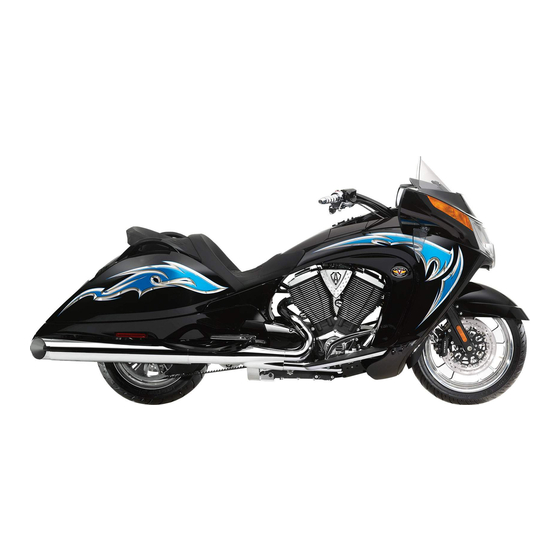
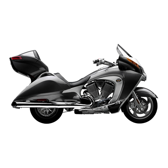
Victory Vision Tour
Ness Signature Series
Victory Vision Tour
Related Manuals for Victory Motorcycles Vision Tour 2013
Summary of Contents for Victory Motorcycles Vision Tour 2013
-
Page 1
2013 Owner’s Manual Victory Vision Tour Ness Signature Series Victory Vision Tour… -
Page 2
For your nearest VICTORY dealer, visit www.polarisindustries.com Polaris Sales Inc., 2100 Hwy. 55 Medina, MN 55340 USA Part No. 9924037 Rev 01 Printed in USA *9924037… -
Page 3
2013 Rider’s Manual Victory Vision ® Tour ® Ness Signature Series Victory Vision Tour… -
Page 4
All reference to RIGHT, LEFT, FRONT, REAR are from the operator’s perspective seated in a normal riding position. Features of VICTORY Motorcycles are covered by U.S. Patent Nos: 6,976,691; 6,407,663; D489670; D482311; D482304; D481980; D481973; D474142. The following are registered trademarks of Polaris Industries Inc.: ®… -
Page 5: Table Of Contents
Table of Contents Introduction ……… 4 Safety .
-
Page 6: Introduction
VIC- TORY dealer. To locate the nearest authorized VICTORY dealer, call 1-800-POLARIS or visit www.polarisindustries.com. VICTORY motorcycles comply with all federal, state and local safety and emission regula- tions for the area of intended sale.
-
Page 7: Safety
Safety About the Rider’s Manual WARNING Failure to follow recommended precautions and procedures could result in severe injury or death. Always heed all safety precautions and follow all operation, inspection and maintenance procedures outlined in this manual. This rider’s manual contains information that is essential to safe riding and proper mainte- nance of your VICTORY motorcycle.
-
Page 8: Safe Riding Practices
47. Failure to do so can result in serious engine damage. • Some VICTORY motorcycles include saddlebags, a windshield, a trunk, or a passenger backrest as standard equipment. To maintain stability, be prepared to reduce the operating…
-
Page 9
Safety Safe Riding Practices Follow these general safe riding practices: • Before each ride, perform the pre-ride inspections as outlined beginning on page 38. Fail- ure to do so may result in damage to the motorcycle or an accident. • Until you’re thoroughly familiar with the motorcycle and all of its controls, practice riding where there is little or no traffic. -
Page 10
Safety Safe Riding Practices • Reduce speed when: • the road has potholes, or is otherwise rough or uneven. • the road contains sand, dirt, gravel or other loose substances. • the road is wet, icy or oily. • the road contains painted surfaces, manhole covers, metal grating, railway crossings or other slippery surfaces. -
Page 11
Safety Safe Riding Practices Carrying a Passenger Do not carry a passenger unless the motorcycle is equipped with passenger seat and passen- ger footrests.. To carry a passenger safely: • Do not exceed the gross vehicle weight rating (GVWR) for your motorcycle. •… -
Page 12: Parking The Motorcycle
Safety Use of Accessories Because VICTORY cannot test and make specific recommendations concerning every acces- sory or combination of accessories sold, the operator is responsible for determining that the motorcycle can be safely operated with any accessories or additional weight. Use the follow- ing guidelines when choosing and installing accessories: •…
-
Page 13
Safety Carrying Cargo Use the following guidelines when attaching cargo or accessories to the motorcycle. Where applicable, these guidelines also refer to the contents of any accessories. • Keep cargo and accessory weight to a minimum, and keep items as close to the motorcycle as possible to minimize a change in the motorcycle’s center of gravity. -
Page 14: Transporting The Motorcycle
Safety Transporting the Motorcycle If you must transport the motorcycle: To loop on frame (one tiedown each side) • Use a truck or trailer. Do not tow the motorcycle with another vehicle, as towing will impair the motorcycle’s steering and handling. •…
-
Page 15: Electromagnetic Interference
Safety Safety Maintenance WARNING Failure to perform safety maintenance as recommended can result in difficult handling and loss of control, which could result in serious injury or death. Always perform the safety maintenance procedures as recommended. Perform maintenance and repairs promptly as outlined in the VICTORY service manual, or see your authorized VICTORY dealer for service.
-
Page 16
Safety Gross Vehicle Weight Rating (GVWR) WARNING! Exceeding the gross vehicle weight rating of your motorcycle can reduce stability and han- dling and could cause loss of control. NEVER exceed the GVWR of your motorcycle. The maximum load capacity of your motorcycle is the maximum weight you may add to your motorcycle without exceeding the GVWR. -
Page 17
Safety Safety and Information Labels Labels are model-specific and market-specific. Your motorcycle may not contain all of the labels shown. See page 83 for seat removal instructions. 1. Windshield Label 2. Manufacturing Information Label (on frame, under rear console cover) 3. -
Page 18: Identification / Component Location
Identification Ignition Key Number Key Number The ignition key number is stamped on the small metal tag attached to the key ring. Remove the tag and record the number on page 105. Store the tag in a safe place. Additional keys can be copied from one of the original keys. A VICTORY key blank is required.
-
Page 19: Left Side View
Identification Left Side View 1. Spark Plugs 2. Power Port 3. Front Brake Caliper 4. Gear Shift Pedal 5. Operator Footrest 6. Sidestand 7. Oil Drain Plug 8. Oil Filter 9. Passenger Footrest 10. Rear Brake Caliper 11. Diagnostic Connector (in sad- dlebag) 12.
-
Page 20: Top View
Identification Top View 1. Windshield 2. Radio Antenna (under dash) 3. Mirror 4. Clutch Fluid Reservoir 5. Clutch Lever 6. Glove Compartment Door 7. Operator Seat 8. Passenger Seat 9. Saddlebag Latch 10. Trim Panel (if equipped) 11. Front Brake Lever 12.
-
Page 21
Identification Rear View 1. Turn Signals (uppermost in lens) 2. Tail Lamps (3 each side) 3. Brake Lamps 4. Exhaust Mufflers 5. License Plate Bracket Console 1. Speakers 2. Fuel Gauge 3. Speedometer 4. Indicator Lamp Display 5. Multi-Function Display 6. -
Page 22: Instruments, Features & Controls
Instruments, Features and Controls Ignition Switch Place the ignition key in the ignition switch to operate the following functions of the switch. Engine Off All electrical circuits are off. The key can be removed. (OFF) Engine On/ All electrical circuits are on. The ignition key cannot be removed. Headlamp, taillight, All Lights running lights, radio and instrument lights illuminate.
-
Page 23: Ignition Switch
Instruments, Features and Controls Ignition Switch Fuel Door Lock 1. Turn the handlebars full left. Fuel Door 2. Turn the key to the OFF position. Release Tip: Do not push the key down when unlocking the fuel door. 3. Turn the ignition key counter-clockwise to release the fuel door latch.
-
Page 24: Instrument Cluster
Instruments, Features and Controls Instrument Cluster The instrument cluster includes the speedometer, tachometer, fuel gauge, volt meter, indica- tor lamps and multi-function display. Indicator Lamps Tachometer Speedometer Volt Meter Fuel Gauge Multi-Function Display Speedometer The speedometer displays vehicle speed in either miles per hour or kilometers per hour. See page 25.
-
Page 25: Indicator Lamps
Instruments, Features and Controls Indicator Lamps Anti-Lock Brake System (ABS) (if equipped) Right Turn High Beam Low Fuel Left Turn Oil Pressure Cruise Control Check Engine Battery Warning Neutral Lamp Indicates Condition Neutral This lamp illuminates when the transmission is in neutral and the ignition key is in the ON or ACC position.
-
Page 26
Instruments, Features and Controls Indicator Lamps Lamp Indicates Condition Low Fuel This lamp illuminates when approximately one gallon (3.8 liters) of fuel remains in the fuel tank. Low Battery This lamp illuminates when battery voltage is low. Make sure the Warning charging system is operating properly. -
Page 27
Instruments, Features and Controls Multi-Function Display Engine Error Codes The error screen displays only when the CHECK Error Code Failure Mode ENGINE light is on or when it goes on and off Number (0-9) Indicator (FMI) during one ignition cycle. Error codes are not stored. -
Page 28
Instruments, Features and Controls Multi-Function Display Clock Tip: The clock must be reset any time the battery has been disconnected or discharged. 1. Turn the key to ON or ACC. Use the mode button to toggle to the odometer display. Tip: If LOW FUEL is flashing, the display will not enter the CLOCK SET mode. -
Page 29: Console Switches
Instruments, Features and Controls Console Switches Optional Hand Grip Accessory Heater Switch Switch Hazard Switch Driving Lamp Switch Hand Grip Heater Switch High Press the top (high heat) or bottom (low heat) of the rocker switch to turn the hand grip heaters on. Move the switch to the center position to turn the heat- ers off.
-
Page 30: Mode Button
Instruments, Features and Controls Seat Heater Switches High Seat heater switches (if equipped) are located on the seat under the left passenger hand grip. The low heat setting is adequate for most conditions. Use the high heat setting with caution. •…
-
Page 31: Horn Switch
Instruments, Features and Controls Headlamp Switch (High/Low) High Beam The headlamp switch is located on the left handlebar. Use the switch to toggle the headlamp to high beam or low beam. The key must be in the ON or ACC position. Beam Tip: To turn the headlamp on, turn the ignition key to ON and tap or press the start switch.
-
Page 32: Turn Signal Switch
Instruments, Features and Controls Turn Signal Switch The turn signal switch is located on the left handlebar. Use the switch to activate a turn signal. The key must be in the ON or ACC position. • Push the switch to the left to activate the left turn signals. •…
-
Page 33: Engine Starter Switch
Instruments, Features and Controls Engine Starter Switch The starter switch is located on the right handlebar. Use the starter switch to start the engine, turn the headlights on and operate in reverse (if equipped). The switch will operate only when the engine stop/run switch is in the RUN position and the transmission is in neutral (or the clutch is disengaged).
-
Page 34: Throttle Control Grip
Instruments, Features and Controls Throttle Control Grip The throttle control grip is located on the Decrease right handlebar. Use the throttle control grip Speed to control engine speed. While seated in the proper riding position: • Rotate the top of the grip rearward to increase engine speed and power.
-
Page 35
Instruments, Features and Controls Brakes Anti-Lock Brake System (ABS) • Operating with non-recommended tires or improper tire pressure may reduce the effec- tiveness of the anti-lock brake system. Always use the recommended size and type of tires specified for your vehicle. Always maintain the recommended tire pressure. •… -
Page 36: Gear Shift Pedal
Instruments, Features and Controls Brakes Rear Brake Pedal The rear brake pedal is located on the right side of the motorcycle. Press downward on the rear brake pedal to apply the rear brake. The rear brake pedal activates the rear brake cal- iper fully while simultaneously activating one of the three pistons in each front brake caliper.
-
Page 37: Glove Compartment
Instruments, Features and Controls Windshield Adjustment Use the motorized windshield adjustment switch (if equipped) to adjust the windshield. See page 29. If the motor- Retaining Clip cycle is not equipped with this feature, you can manually adjust the windshield. 1. Park the motorcycle on a firm, level surface. Turn the key to the OFF position.
-
Page 38
Instruments, Features and Controls Sidestand The sidestand is located on the left side of the motorcy- cle. Sidestand Interlock Switch This vehicle is equipped with a sidestand interlock switch that prevents the engine from starting, although it will crank, if the sidestand is extended and the transmis- sion is in gear. -
Page 39: License Plate
Instruments, Features and Controls License Plate The license plate module is equipped with an LED light to illluminate the license plate. Always make sure the license plate is properly installed before operating the motorcycle. 1. Align the top edge of the license plate with the top edge of the license plate window. 2.
-
Page 40: Pre-Ride Inspections
Pre-Ride Inspections To keep your motorcycle in safe operating condition, always perform the recommended pre- ride inspections before each ride. This is especially important before making a long trip and when removing the motorcycle from storage. WARNING! Failure to perform the recommended pre-ride inspections could result in component failure while riding, which could result in serious injury or death.
-
Page 41: Operation
Pre-Ride Inspections Turn the ignition key to the ON position and move the stop/run switch to RUN before per- forming the following electrical inspections. Return the ignition key to the OFF position after completing these inspections. If inspection of any electrical item reveals component failure, repair or replace the component before operating the motorcycle.
-
Page 42: Engine Oil Level
Pre-Ride Inspections Engine Oil Level The oil fill cap/dipstick is located on the right side of the vehicle. Always use the recommended oil. See page 105. Tip: The engine must be at normal operating temperature when checking the oil level. 1.
-
Page 43: Front Brake Lever
Pre-Ride Inspections Tires Tire Pressure Check tire pressure before riding, when the tires are cold. This will provide the most accurate reading, as riding warms the tires and increases tire air pressure. Adjust tire pressure as needed based on the total weight of your intended load. See page 77. Tire Condition Inspect the tire sidewalls, road contact surface and tread base.
-
Page 44: Rear Brake Pedal
Pre-Ride Inspections Rear Brake Pedal 1. Press downward on the rear brake pedal. It should move freely and smoothly. It should not move more than 3/8 inch (8 mm) before resistance is firm. It should continue to feel firm, without loss of pres- sure, until the pedal is released.
-
Page 45: Brake Pads
Pre-Ride Inspections Brake Lines Inspect all brake hoses and connections for dampness or stains from leaking or dried fluid. Tighten any leaking connections and replace components as necessary. Tip: Refer to the service manual or contact your dealer for fastener torque values. WARNING! Brake fluid leaks or low brake fluid levels could cause brake system failure, which could result in serious injury or death.
-
Page 46
Pre-Ride Inspections Hydraulic Clutch Minimum 1. Position the motorcycle on level ground in the fully Level upright position. Position the handlebars so that the clutch fluid reservoir is level. 2. View the fluid level through the sight glass. The fluid should be clear. -
Page 47: Front Suspension
Pre-Ride Inspections Front Suspension Inspect the front forks for oil leaks or damage, and verify smooth suspension operation. See page 68. Steering 1. On level ground, straddle the motorcycle and bring it to the fully upright position. Turn the handlebars from stop to stop. The action should be smooth, but not loose. 2.
-
Page 48
Pre-Ride Inspections Sidestand 1. On level ground, straddle the motorcycle and bring it to the fully upright position. 2. Move the sidestand up to the stored position and down to the fully extended position sev- eral times. It should move smoothly and quietly. Make sure the return spring holds the sidestand tightly in place when the sidestand is in the stored position. -
Page 49: Operation
Operation The operation section of this manual describes how to ensure maximum performance and longevity through the proper care and operation of your motorcycle. Tip: Even if you’re an experienced motorcycle operator or passenger, read all of the safety information in this manual before operating the motorcycle.
-
Page 50
Operation Fueling Always refuel on level ground with the sidestand down. Review the fuel warnings. See page 12. Use only the recommended fuel. See page 105. Hold the nozzle while filling. Do not rest the weight of the nozzle and hose on the filler neck. Do not leave the nozzle unattended. WARNING! Overflows or spilled gasoline could contact a hot engine or exhaust system and cause a fire, which could result in serious injury or death. -
Page 51: Starting The Engine
Operation Starting the Engine The starter interlock system allows the engine to be started only when the transmission is in neutral, or when the transmission is in gear with the clutch disengaged (clutch lever pulled in) and the sidestand retracted. Tip: If the motorcycle runs out of fuel, prime the system before attempting to restart the engine.
-
Page 52: Shifting Gears
Operation Shifting Gears WARNING! Forced shifting (with clutch engaged) could cause damage to the engine, transmission and drive train. Such damage could cause loss of control, which could result in serious injury or death. Always pull the clutch lever fully toward the handlebars to disengage the clutch before shifting gears. This motorcycle is equipped with a six-speed transmis- Overdrive sion.
-
Page 53
Operation Shifting Gears Recommended Shift Points Upshifting (Accelerating) Downshifting (Decelerating) Gear Change Recommended Speed Gear Change Recommended Speed 1 to 2 18 MPH (29 km/h) O/D to 5 50 MPH (80 km/h) 2 to 3 30 MPH (48 km/h) 5 to 4 35 MPH (56 km/h) 3 to 4 40 MPH (64 km/h) -
Page 54
Operation Using Cruise Control If equipped, the cruise control is located on the right handlebar. Make sure you read this sec- tion and understand how to safely operate this feature before using the cruise control. Cruise Type R: Verify which type of cruise control is installed on your vehicle by checking for a label in the left saddlebag. -
Page 55
Operation Using Cruise Control Resume Speed 1. Disengage the cruise control with the brake, throttle or clutch. 2. Press the resume button (RES) to return to the set speed. Resume (Type R: You must wait at least 3 seconds after disengag- ing cruise control before pressing resume. -
Page 56: Stopping The Engine
Operation Stopping the Engine Before stopping the engine, bring the motorcycle to a complete stop. Shift to neutral or dis- engage the clutch. WARNING! Stopping the engine with the transmission in gear while the motorcycle is moving could cause loss of rear wheel traction or engine and transmission damage, which could cause loss of control and serious injury or death.
-
Page 57
Operation Reverse Operation (if equipped) NOTICE: Do not attempt to engage or disengage the reverse system when the motorcycle is moving. Before Operating in Reverse: • always sit on the motorcycle with legs astride and both feet on the ground. •… -
Page 58: Maintenance
Maintenance Safety During Service Procedures WARNING Failure to follow recommended precautions and procedures could result in severe injury or death. Always heed all safety precautions and follow all operation, inspection and maintenance procedures outlined in this manual. • Improperly installed or adjusted components can make the motorcycle unstable or hard to handle. Improperly installed electrical components can cause engine or electrical system failure.
-
Page 59: Periodic Maintenance
Maintenance Proper maintenance assures the highest level of safety, durability and dependability for your motorcycle. • Have your VICTORY dealer perform the break-in maintenance procedures when the motorcycle’s odometer registers 500 miles (800 km). • Perform the recommended periodic maintenance at the intervals specified in the periodic maintenance table beginning on page 58.
-
Page 60
Maintenance Periodic Maintenance Table See table key below Odometer Reading in Miles (Kilometers) Component Page ABS Components Air Filter Battery Brake Fluid Brake Pads Clutch Cable (Mechanical) Clutch Fluid Clutch Lever (Hydraulic) Clutch Lever 72, 73 (Mechanical) Control Cables 71, 73 Crankcase Vent Drive Belt Drive Belt Adjustment… -
Page 61: Maintenance Log
Maintenance Maintenance Log Maintenance Performed Miles / Km Notes Performed…
-
Page 62
Maintenance Engine Oil / Filter Change Change the engine oil at the intervals specified in the periodic maintenance table beginning on page 58. 1. Start the engine and allow it to idle for several min- utes. Stop the engine. Tip: The engine must be at normal operating temperature before changing the oil. -
Page 63: Air Filter
Maintenance Engine Oil / Filter Change 8. Start the engine and allow it to idle for several min- utes. Stop the engine. NOTICE: After an oil change, the low oil pressure indicator remains illuminated longer than usual before going out. Revving the engine while the low oil pressure indicator is illuminated can damage the engine.
-
Page 64: Drive Belt Condition
Maintenance Drive Belt Condition Replace the drive belt if it is cracked or has bro- ken teeth or frayed edges. No matter its condi- tion, the drive belt should be replaced at periodic intervals. See the VICTORY Service Manual or an authorized VICTORY dealer. DO NOT attempt to check belt tension if the belt has been exposed to rain or washing within a 24 hour period or if the belt is hot from riding.
-
Page 65
Maintenance Drive Belt Tension Data Specifications are listed below for deflection and sonic tension. Sonic tension measurement requires Gates Sonic Tension Meter 507C or an equivalent. Drive Belt Deflection (Using PV-43532 Tension Gauge) Deflection VISION 32 mm ± 0.5 mm Drive Belt Sonic Tension (Using Sonic Tension Meter) Sonic Tension Required Data… -
Page 66
Maintenance Drive Belt Tension Inspection 1. Elevate and support the motorcycle with the rear tire slightly off the floor. CAUTION! Make sure the motorcycle is stable when elevated. Injury may occur if the motorcycle tips or falls. 2. Place the transmission in neutral. Drive Belt 3. -
Page 67
Maintenance Drive Belt Tension Adjustment 1. Move the wheel to the tight spot location deter- mined previously. 2. Loosen the rear axle nut on the left side. 3. Turn each axle adjuster nut clockwise an equal amount to tighten the belt (reduce deflection) or an equal amount counter-clockwise to loosen the belt (increase deflection). -
Page 68: Rear Suspension Adjustment
Maintenance Rear Suspension Adjustment For riding comfort and to ensure proper ground clearance, adjust rear shock air pressure as specified on the label located in left saddlebag area (see below). Follow these guidelines when adjusting: • Park the motorcycle with the sidestand down on a firm, level surface.
-
Page 69
Maintenance Rear Suspension Adjustment 1. Park the motorcycle with the sidestand down Bleed on a firm, level surface. Remove all riders Button Fitting and cargo. 2. Open the left saddlebag door. Remove the cap from the air fitting. 3. Refer to the shock label to determine the rec- ommended air pressure. -
Page 70: Swing Arm / Rear Axle Inspection
Maintenance Swing Arm / Rear Axle Inspection 1. Sit in the operator’s seat and slowly bounce the rear suspension a few times. Make sure the suspension moves freely without binding. Listen for abnormal noises. 2. Elevate and support the motorcycle with the rear tire slightly off the floor. CAUTION! Make sure the motorcycle is stable when elevated.
-
Page 71: Fast Idle
Maintenance Steering Head Inspection View 1. Elevate and support the motorcycle with the front tire slightly off the floor. CAUTION! Make sure the motorcycle is stable when elevated. Injury may occur if the motorcycle tips or falls. 2. Turn the handlebars from stop to stop. The action should be smooth but not loose.
-
Page 72: Throttle Control Inspection
Maintenance Throttle Control Inspection 1. With the engine OFF, rotate the throttle control grip fully open and then release it. It should rotate smoothly from the rest position to the completely open position. It should return to the rest position quickly when released. 2.
-
Page 73: Hydraulic Clutch Fluid
Maintenance Throttle Cable Lubrication Lubricate control cable ends at the intervals recommended in the periodic maintenance table beginning on page 58. NOTICE: External casings are factory-lubricated. Additional lubrication could be detrimental to cable performance. Verify proper routing and smooth movement. Inspect for damage to the external casing, and inspect exposed cable wire for fraying, kinks or corrosion.
-
Page 74
Maintenance Hydraulic Clutch Fluid 1. Straddle the motorcycle and bring it to the fully upright position. Position the handlebars so that the Minimum fluid reservoir is level. Level 2. Wipe the fluid container and the area around the res- ervoir cover with a clean cloth. 3. -
Page 75
Maintenance Mechanical Clutch Lever Lubrication 1. Remove the right side access cover. Loosen the clutch Pivot Screw cable adjuster lock nut. 2. Turn the cable adjuster completely inward to provide maximum lever freeplay. 3. Remove the clutch lever pivot nut and screw. Disconnect the clutch cable from the clutch lever. -
Page 76: Brake Fluid Precautions
Maintenance Front Brake Lever 1. See page 33 for front brake lever reach adjustments. 2. Lubricate the pivot bushing at the intervals recom- mended in the periodic maintenance table beginning on page 58. Also lubricate any time binding is evident. Use VICTORY All Purpose Grease or equivalent.
-
Page 77: Rear Brake Fluid
Maintenance Rear Brake Fluid 1. Position the motorcycle on level ground in the fully upright position. 2. The rear brake fluid reservoir is located near the rear brake pedal, just inside the right lower leg fairing. Wipe the fluid container and the area around the reservoir cover with a clean cloth.
-
Page 78: Wheel Inspection
Maintenance Brake Disc Inspection / Cleaning 1. Inspect brake pads as outlined on page 43. 2. Inspect brake discs for nicks, scratches, cracks or other damage. Inspect the thickness of each brake disc at four or more locations around the disc. If any disc is worn to the minimum thickness at the thinnest point, or if a disc is damaged, see your VICTORY dealer for replacement.
-
Page 79: Tire Condition
Maintenance Tires WARNING Operating the motorcycle with improper tires or with improper or uneven tire pressure could cause loss of control or accident. Always use the correct size and type of tires specified for your vehicle. Always maintain proper tire pressure as recommended in the owner’s manual and on safety labels. Tire Replacement To meet European Union tire directive 97/24 Chapter 1, always replace tires with the tires specified in the table below and in the specifications section of this manual.
-
Page 80: Spark Plugs
Maintenance Spark Plugs Replace spark plugs at the intervals recommended in the periodic maintenance table beginning on page 58. Always replace spark plugs in pairs. 031-.035 inch (0.8-0.9 mm) Spark Plug Specifications Spark Plug Type NGK DCPR6E Spark Plug Gap .031-.035 inch (0.8-0.9 mm) Spark Plug Torque 10.8-14.5 ft-lbs (14.6-19.7 Nm)
-
Page 81
Maintenance Battery The motorcycle battery is a sealed, maintenance-free battery. Do not remove the battery cap strip for any reason. Keep the battery connections clean and tight at all times. WARNING Battery electrolyte is poisonous. It contains sulfuric acid. Serious burns can result from contact with skin, eyes or clothing. -
Page 82: Battery Removal
Maintenance Battery Removal 1. Turn the handlebars full right. 2. Remove the five belly pan screws. Tool: 6 mm Allen wrench 3. Remove the screw that joins the two side grills. Tip: The grill screw is placed in the FRONT hole. The center belly pan screw uses the rear hole.
-
Page 83: Battery Installation
Maintenance Battery Installation WARNING! Improperly connecting or disconnecting battery 85 in-lbs (10 Nm) cables can result in an explosion and cause serious injury or 36 in-lbs (4 Nm) death. When removing the battery, always disconnect the negative (black) cable first. When reinstalling the battery, always connect the negative (black) cable last.
-
Page 84: Sidestand Lubrication
Maintenance Ignition Switch / Lock Lubrication Periodically lubricate the ignition switch and door locks. We recommend the use of VIC- TORY Multi-Purpose Lubricant. 1. Spray lubricant directly into the ignition switch and into each lock cylinder for 1-2 sec- onds. 2.
-
Page 85: Windshield Trim Panel Removal
Maintenance Seat Removal / Installation 1. Open the glove compartment door and the fuel door. 2. Lift the console trim panel straight upward at each corner to remove it. Do not tip the panel rearward. 3. Remove the two seat bolts. Tool: 4 mm Allen wrench 4.
-
Page 86
Maintenance Street Trim Panel Removal 1. Remove the seat, license plate and bracket. See Tabs page 83. 2. Open the saddlebags. 3. Working from top to bottom, lift each edge of the tail molding to release the tabs. Lift the tail Trim molding just enough to provide clearance to Panel… -
Page 87: Trunk Installation
Maintenance Trunk Removal Wire Harness 1. Remove the seat. See page 83. 2. Disconnect the trunk wire harness. 3. Remove the license plate. 4. Remove the two 4 mm Allen screws from bot- tom of the license plate bracket. Remove the bracket.
-
Page 88: Headlamp Bulb Replacement
Maintenance Headlamp Bulb Replacement 1. Remove the air filter. See page 61. 2. Pull the sealing boot away from the back of the bulbs and housing. 3. Press the looped end of the wire bulb retainer clip and swing the end toward the center of the bulb to release it from the latch tab.
-
Page 89
Maintenance Taillight / Brake Light / Turn Signal Bulb Replacement 1. Open the saddlebags. Screws Tip: (Removal of the trunk or street panel is not necessary.) 2. Remove the license plate and bracket. See page 83. 3. Working from top to bottom, lift each edge of the tail molding to release the tabs. -
Page 90: Headlamp Aim Adjustment
Maintenance Headlamp Aim Adjustment The high beam should shine straight forward. The low beam will spread more toward the right (U.S./Canada). 1. Verify that tire pressure is at specification. See 25 ft. (7.6 m) page 77. Verify that rear suspension ride height (preload) is at specification.
-
Page 91: Fuse Replacement
Maintenance Fuse Boxes Remove the windshield trim panel to access the fuses, auto-reset circuit breakers and relays. See page 83. Use the fuse puller provided in the tool kit to remove a fuse. Left Fuse Box Right Fuse Box Fuse Replacement 1.
-
Page 92: Electrical Precautions
Maintenance Electrical Precautions Be aware of the following “DO’s” and “DO NOT’s” regarding the electrical system to avoid disruption of electrical signals and possible system malfunction. • DO use ONLY genuine VICTORY parts and accessories designed for your model and fol- low the instructions provided.
-
Page 93: Road Test
Maintenance Elevating the Motorcycle WARNING! Serious injury or death can occur if the motorcycle tips or falls. Make sure the motorcycle will not tip or fall while elevated or while on the sidestand. Some procedures require raising the motorcycle to remove weight from the component being inspected.
-
Page 94: Troubleshooting
Maintenance Troubleshooting For your personal safety, do not attempt inspection or repairs not fully described in this rider’s manual. Contact an authorized VICTORY dealer for service if you cannot determine the cause of a problem or if the inspection / repair exceeds your mechanical ability or tool resources.
-
Page 95
Maintenance Troubleshooting Shifting Difficulties or Hard to Find Neutral Possible Cause Possible Remedy/Action Shift Linkage Bushings Dry Or Worn Lubricate shift linkage. Engine Oil Level Incorrect Or Wrong Type Inspect level and quality of oil. See page 40. Hydraulic Clutch Fluid Contaminated Flush hydraulic clutch fluid (see dealer). -
Page 96
Maintenance Service Manual Availability Some procedures are beyond the scope of this manual. See your dealer to purchase a VIC- TORY Service Manual for your motorcycle. Some procedures provided in the Service Manual require specialized knowledge, equipment, and training. Be sure you have the required technical skills and tools that are needed before you attempt ANY service on your motorcycle. -
Page 97: Cleaning And Storage
Cleaning and Storage VICTORY Cleaning Products This section provides tips on the very best way to clean, polish and preserve every surface of your beautiful new VICTORY Motorcycle. We recommend the use of our new Pure VIC- TORY cleaning and polishing products and accessories, which have been specially designed to offer the best care possible for your VICTORY motorcycle.
-
Page 98
Cleaning and Storage Washing the Motorcycle There are two totally different styles of motorcycle washing and there is a Pure VICTORY Polish product for each style. Standard “Bucket Wash” This is the conventional way to wash your motorcycle. We recommend the use of Pure VIC- TORY Bike Wash Concentrate, a concentrated gentle product formulated to clean without diminishing the life of any durable polish. -
Page 99
Cleaning and Storage Washing the Motorcycle Quick Clean-Ups For quick clean-ups between washings, or when water is not available, use Pure VICTORY Spray & Wipe Instant Detailer, a complete spray-and-wipe product designed to clean and polish all surfaces. It works quickly and easily and is silicone-free so it leaves no oily nor white residue. -
Page 100
Cleaning and Storage Polishing the Motorcycle There are now two totally different styles of polishing or protecting your paint and chrome. Standard Method of Polishing Paint and Chrome Pure VICTORY Windshield, Paint and Chrome Polish is a unique formula designed to pro- duce a glass-like shine on painted or clear-coated finishes and chrome surfaces. -
Page 101
Cleaning and Storage Polishing the Motorcycle Premium Polishing for Long-Lasting Protection This newer style of polishing paint and chrome utilizes the latest in high-quality polymer technology that provides the longest-lasting protection available in the polish industry today. Pure VICTORY Liquid Spray Wax for Windshields, Paint & Chrome is formulated for pol- ishing after washing and can be sprayed on wet or dry surfaces. -
Page 102: Clean And Protect The Motorcycle
Cleaning and Storage If you will not operate the motorcycle for several months, such as during the winter, store the motorcycle to prevent damage to the fuel system and the battery and to protect components from corrosion or deterioration. During storage you might use products that are potentially hazardous;…
-
Page 103: Battery Care
Cleaning and Storage Engine Protection Change the engine oil. See page 60. Carbon deposits and combustion acids, normally sus- pended in the engine oil when in service, settle on internal engine components during stor- age. Settled deposits can cause engine damage or internal corrosion. Battery Care 1.
-
Page 104: Removal From Storage
Cleaning and Storage Removal From Storage 1. Remove the cover and unlock the front forks (if locked). 2. Verify that tire pressure is at specification. 3. Install the battery and perform an electrical inspection. 4. Check the oil level. If the motorcycle was stored in an area subject to wide swings in temperature and humidity (such as outdoors), change the engine oil before starting the engine.
-
Page 105: Warranty
NO WARRANTY COVERAGE WILL BE ALLOWED UNLESS YOUR VICTORY MOTORCYCLE IS REGISTERED WITH VICTORY MOTORCYCLES DIVISION OF POLARIS SALES INC. Initial dealer preparation and set-up of your VICTORY Motorcycle is very important in ensuring trouble-free operation. Pur- chasing a motorcycle in the crate or without proper dealer set-up will void your warranty coverage.
-
Page 106: Victory Motorcycle Warranty Policy
ABILITY AND FITNESS FOR A PARTICULAR PURPOSE) ARE LIMITED IN DURATION TO THE ABOVE ONE YEAR WARRANTY PERIOD. VICTORY MOTORCYCLES DIVISION OF POLARIS SALES INC. FURTHER DISCLAIMS ALL EXPRESS WARRANTIES NOT STATED IN THIS WARRANTY OTHER THAN EMISSIONS AND EXCISE WARRAN- TIES.
-
Page 107: Specifications
Specifications Fuel Recommendation For best performance, use only unleaded gasoline with a 91 pump octane minimum (R+M/2 Method). DO NOT USE E-85 GASOLINE OR GASOLINE CONTAINING METHANOL. Using E85 or gasoline / methanol blends can result in poor starting and driveability, and may damage critical fuel system components.
-
Page 108
Specifications Vision Tour Ness Vision Dimensions (Dimensions and specifications may vary with features, options and accessories) Overall Length 104.9 in. (266.5 cm) 104.9 in. (266.5 cm) Overall Width 45.2 in. (114.7 cm) 45.2 in. (114.7 cm) Overall Height 58.5 in. (148.5 cm) 58.5 in. -
Page 109
Specifications All Vision Models Capacities Engine Oil 5 qt (4.75 l) [Approximately 4.5 qt (4.25 l) at oil change] Fuel 6.0 Gallons (22.7 l) Fuel Reserve 1.0 Gallon (3.8 l) Engine Engine Type ® VICTORY Freedom 106 / 6 V-Twin Configuration 50°… -
Page 110
Specifications All Vision Models Wheels And Tires Front Wheel Type / Size Cast or Billet 18 x 3.0 inch Front Tire Type / Size DUNLOP Elite 3 — 130/70R18 63H Radial Rear Wheel Type / Size Cast or Billet 16 x 5.0 inch Rear Tire Type / Size DUNLOP Elite 3 — 180/60R16 M/C 80H Radial Electrical… -
Page 111: Audio
Audio System Overview Audio System Introduction Not all motorcycles are equipped with all components discussed in the audio section of this manual. Components not installed at the factory can be purchased from and installed by your local VICTORY dealer. Software Updates Radio system software should be updated annually to ensure the best performance.
-
Page 112: Operation
Audio System Overview Main User Interface Audio Controls Operation of the left handlebar audio con- U.S.A. Sources trols is outlined in greater detail on the fol- • FM • AM lowing pages. • WX • AUX (NAV MP3, AUX or iPod) •…
-
Page 113
Audio System Overview Citizens Band (CB) Radio Audio System Power Controls The ignition key must be in the ACC or ON position to use the audio system. If equipped, the operator’s CB radio con- trols are located on the left handlebar above With the key in the ACC or ON position and the audio controls. -
Page 114: Operation
Audio System Operation Audio Volume Control Selecting Audio Sources The driver can adjust volume for the front Press and release S/E or SRC until the and rear speakers, turn the speakers off or desired source is active. on and mute the system audio. Audio Mute Press and release MUTE to drop audio…
-
Page 115
Audio System Operation Selecting Audio Sources Audio Tuning NAV MP3 source active: Use the tuner on the left control to select U.S. / European models radio stations. Press and release ICOM NAV MP3 TUNE (+) or TUNE CB19 (-) to locate stations in single-step increments. -
Page 116
Audio System Operation Audio Mode Menus Entering Mode Menus Fader Setting Press and release the MODE Press (+) or (-) on button on the console panel to the console panel enter the audio system mode to change settings. menus. Continue to press and External release the MODE button EXTERNAL SPKRS… -
Page 117
Audio System Operation Audio Mode Menus CB Headset Volume Controls (if equipped) The headsets have three separate volume settings: Intercom (ICOM) volume, CB receive volume and entertainment (ENT) volume. Always position headsets with the speakers directly over your ears to ensure the best sound quality and volume. Tip: The driver can turn off the external speakers and listen to audio only through the headsets. -
Page 118
Audio System Operation Audio Mode Menus To change mode settings, enter the mode menu. Press (+) or (-) on the console panel to change settings. Press S/E to save and exit. Tip: Sources and menu options will be displayed only for installed components. ICOM Volume AUX Mode Press (+) or (-) on… -
Page 119: Weather Band (Wx)
Audio System Operation Audio Mode Menus Weather Band (WX) Weather band channels are broadcast by the To change mode settings, enter the mode National Oceanic and Atmospheric Admin- menu. Press (+) or (-) on the console panel istration (NOAA). NOAA operates more to change settings.
-
Page 120: Cb Radio — Icom
CB Radio / ICOM System CB/ICOM Introduction CB Channels In the U.S.A., refer to the Federal Commu- When the CB radio system is active, “CB” nications Commission (FCC) Plain Rules and the active channel will display. pamphlet accompanying this rider’s manual for a comprehensive guide of citizens band (CB) radio rules and regulations.
-
Page 121
CB Radio / ICOM System Push-to-Talk (PTT) Squelch Press and hold the Squelch blocks unde- top or bottom of the sired signals and noise PTT button to trans- by allowing the recep- mit over CB radio. tion of signals only The passenger must over a specified level. -
Page 122
CB Radio / ICOM System Local/Distant CB Radio Mode To change mode Distant: Use this setting for weaker signals. CB LO / DX MODE settings, enter the Receiver sensitivity will be increased. Static DISTANT mode menu. Press and noise levels are increased. (+) or (-) on the Local: Use this setting for stronger signals CB LO / DX MODE… -
Page 123: Headset Receptacles
CB Radio / ICOM System ICOM System VOX Break Setting Driver ICOM Volume To change Push COM or ICOM or (+) or (-) on the ICOM VOL 15 settings, enter the console panel to adjust the sensitivity set- mode menu. Press ting.
-
Page 124: Aux — Ipod
AUX / iPod Input Cable Setup The AUX and iPod input cables are con- To change an input cable: nected to the audio system through a small 1. Open the left console storage bin. hole in the left console storage bin. Only 2.
-
Page 125
AUX / iPod Getting Started The ignition key must be in the ACC or ON When iPod is active, the console screen will position to use the audio system. display “iPod” as the active source and iPod information in the display screen. Tip: To prevent battery drain, do not leave the key in the ACC position for long periods. -
Page 126: Ipod Playlists
AUX / iPod iPod Playlists iPod Tuning Press TUNE (+) or TUNE (-) once to move Access the iPod’s main music library and one track forward or backward. Press the user-defined playlists with the console pre- button twice (double click) to bring up the set buttons.
-
Page 127: Xm Radio
XM Radio About XM Radio XM is North America’s number one satellite radio company, offering an extraordinary vari- ety of commercial-free music, plus the best in premier sports, news, talk radio, comedy, chil- dren’s and entertainment programming, broadcast in superior digital audio quality coast to coast.
-
Page 128: Xm Radio Menu Options
XM Radio Getting Started The ignition key must be in the ACC or ON XM Radio Reception position to use the audio system. If the XM radio system is not receiving a Tip: To prevent battery drain, do not leave the signal due to being indoors (or any overhead key in the ACC position for long periods.
-
Page 129: Xm Radio Categories
XM Radio XM Radio Settings XM Radio Categories To access the menus, turn the audio system With XM as the active source, use the power on and change the active source to MODE button on the console to scroll to the XM Radio.
-
Page 130: Nav Mp3
NAV MP3 Navigation MP3 Introduction Please read this manual and the GARMIN ZUMO 660 NAV MP3 information provided with your player to become familiar with all unit features and operation. The audio integration kit must be installed to enable outputs from the NAV MP3 (such as navigation instructions or user-loaded MP3 media files) to play through the headsets or speakers.
-
Page 131: Index
Index About the Rider’s Manual….5 Brakes ABS……. . . 32-33 Disc Inspection/Cleaning .
-
Page 132
Index Display Units, Standard/Metric ….25 Fuel Recommendation….. 105 Drive Belt Fuel System Inspection . -
Page 133: Windshield
Index Labels, Information……15 Panel Installation, Street Trim ….84 Labels, Safety .
-
Page 134
Index Starter Interlock Switch ….30 Tilt Sensor ……. 28 Steering Head Inspection.
- Manuals
- Brands
- Victory Motorcycles Manuals
- Motorcycle
- Vision Tour
- Rider’s manual
-
Contents
-
Table of Contents
-
Troubleshooting
-
Bookmarks
Quick Links
2016 Rider’s Manual
Victory Vision Tour
Related Manuals for Victory Motorcycles Vision Tour
Summary of Contents for Victory Motorcycles Vision Tour
-
Page 1
2016 Rider’s Manual Victory Vision Tour… -
Page 2
California Proposition 65 Warning This product contains or emits chemicals known to the state of California to cause cancer and birth defects or other reproductive harm. -
Page 3
2016 Rider’s Manual ® Victory Vision Tour… -
Page 4
All reference to RIGHT, LEFT, FRONT, REAR are from the operator’s perspective seated in a normal riding position. Features of VICTORY Motorcycles are covered by U.S. Patent Nos: 6,976,691; 6,407,663; D489670; D482311; D482304; D481980; D481973; D474142. The following are registered trademarks of Polaris Industries Inc.: ®… -
Page 5
WARNING Improper vehicle use can result in SEVERE INJURY or DEATH. NEVER Operate: • If you are under the age of 16 and without a driver’s license with motorcycle endorsement • Under the influence of drugs or alcohol • Off-road •… -
Page 7: Table Of Contents
Table of Contents Introduction ……… 6 Safety .
-
Page 8: Introduction
VICTORY dealer. To locate the nearest authorized VICTORY dealer, call 1-800-POLARIS or visit www.polaris.com. VICTORY motorcycles comply with all federal, state and local safety and emission regulations for the area of intended sale.
-
Page 9: Safety
Safety About the Rider’s Manual WARNING Failure to follow recommended precautions and procedures could result in severe injury or death. Always heed all safety precautions and follow all operation, inspection and maintenance procedures outlined in this manual. This rider’s manual contains information that is essential to safe riding and proper maintenance of your VICTORY motorcycle.
-
Page 10: Safe Riding Practices
49. Failure to do so can result in serious engine damage. • Some VICTORY motorcycles include saddlebags, a windshield, a trunk, or a passenger backrest as standard equipment. To maintain stability, be prepared to reduce the operating…
-
Page 11
Safety Safe Riding Practices Follow these general safe riding practices: • Before each ride, perform the pre-ride inspections as outlined beginning on page 40. Failure to do so may result in damage to the motorcycle or an accident. • Until you’re thoroughly familiar with the motorcycle and all of its controls, practice riding where there is little or no traffic. -
Page 12
Safety Safe Riding Practices • Reduce speed when: • the road has potholes, or is otherwise rough or uneven. • the road contains sand, dirt, gravel or other loose substances. • the road is wet, icy or oily. • the road contains painted surfaces, manhole covers, metal grating, railway crossings or other slippery surfaces. -
Page 13
Safety Safe Riding Practices Carrying a Passenger Do not carry a passenger unless the motorcycle is equipped with passenger seat and passenger footrests.. To carry a passenger safely: • Do not exceed the gross vehicle weight rating (GVWR) for your motorcycle. See the manufacturer’s label (on the left side of the frame at the steering head). -
Page 14: Parking The Motorcycle
Safety Use of Accessories Because VICTORY cannot test and make specific recommendations concerning every accessory or combination of accessories sold, the operator is responsible for determining that the motorcycle can be safely operated with any accessories or additional weight. Use the following guidelines when choosing and installing accessories: •…
-
Page 15
Safety Carrying Cargo Use the following guidelines when attaching cargo or accessories to the motorcycle. Where applicable, these guidelines also refer to the contents of any accessories. • Keep cargo and accessory weight to a minimum, and keep items as close to the motorcycle as possible to minimize a change in the motorcycle’s center of gravity. -
Page 16: Transporting The Motorcycle
Safety Transporting the Motorcycle If you must transport the motorcycle: To loop on frame (one tiedown each side) • Use a truck or trailer. Do not tow the motorcycle with another vehicle, as towing will impair the motorcycle’s steering and handling. •…
-
Page 17: Electromagnetic Interference
Safety Safety Maintenance WARNING Failure to perform safety maintenance as recommended can result in difficult handling and loss of control, which could result in serious injury or death. Always perform the safety maintenance procedures as recommended in this manual. Perform maintenance and repairs promptly as outlined in the VICTORY service manual, or see your authorized VICTORY dealer for service.
-
Page 18
Safety Gross Vehicle Weight Rating (GVWR) WARNING! Exceeding the gross vehicle weight rating of your motorcycle can reduce stability and handling and could cause loss of control. NEVER exceed the GVWR of your motorcycle. The maximum load capacity of your motorcycle is the maximum weight you may add to your motorcycle without exceeding the GVWR. -
Page 19: Reporting Safety Defects
Safety Safety and Information Labels Labels are model-specific and market-specific. Your motorcycle may not contain all of the labels shown. See page 85 for seat removal instructions. 1. Windshield Label 2. Vehicle Identification Number (VIN) (on frame, under rear console cover) 3.
-
Page 20: Identification / Component Location
Identification Ignition Key Number Key Number The ignition key number is stamped on the small metal tag attached to the key ring. Remove the tag and record the number on page 113. Store the tag in a safe place. Additional keys can be copied from one of the original keys. A VICTORY key blank is required.
-
Page 21: Left Side View
Identification Left Side View 1. Spark Plugs 2. Power Port 3. Front Brake Caliper 4. Gear Shift Pedal 5. Operator Footrest 6. Sidestand 7. Oil Drain Plug 8. Oil Filter 9. Passenger Footrest 10. Rear Brake Caliper 11. Diagnostic Connector (in saddlebag) 12.
-
Page 22: Top View
Identification Top View 1. Windshield 2. Radio Antenna (under dash) 3. Mirror 4. Clutch Fluid Reservoir 5. Clutch Lever 6. Glove Compartment Door 7. Operator Seat 8. Passenger Seat 9. Saddlebag Latch 10. Trim Panel (if equipped) 11. Front Brake Lever 12.
-
Page 23
Identification Rear View 1. Turn Signals (uppermost in lens) 2. Tail Lamps (3 each side) 3. Brake Lamps 4. Exhaust Mufflers 5. License Plate Bracket Console 1. Speakers 2. Fuel Gauge 3. Speedometer 4. Indicator Lamp Display 5. Multi-Function Display 6. -
Page 24: Instruments, Features & Controls
Instruments, Features and Controls Ignition Switch Place the ignition key in the ignition switch to operate the following functions of the switch. All electrical circuits are off. The key can be removed. All electrical circuits are on. The ignition key cannot be removed. Headlamp, taillight, running lights, radio and instrument lights illuminate.
-
Page 25: Ignition Switch
Instruments, Features and Controls Ignition Switch Fuel Fuel Door Lock Door 1. Turn the handlebars full left. Release 2. Turn the key to the OFF position. Tip: Do not push the key down when unlocking the fuel door. 3. Turn the ignition key counter-clockwise to release the fuel door latch.
-
Page 26: Instrument Cluster
Instruments, Features and Controls Instrument Cluster The instrument cluster includes the speedometer, tachometer, fuel gauge, volt meter, indicator lamps and multi-function display. Indicator Lamps Tachometer Speedometer Volt Meter Fuel Gauge Multi-Function Display Speedometer The speedometer displays vehicle speed in either miles per hour or kilometers per hour. See page 27.
-
Page 27
Instruments, Features and Controls Indicator Lamps Anti-Lock Brake System (ABS) (if equipped) Right Turn High Beam Low Fuel Left Turn Oil Pressure Cruise Control Check Engine Battery Warning Neutral Lamp Indicates Condition Neutral This lamp illuminates when the transmission is in neutral and the ignition key is in the ON or ACC position. -
Page 28: Indicator Lamps
Instruments, Features and Controls Indicator Lamps Lamp Indicates Condition Low Fuel This lamp illuminates when approximately one gallon (3.8 liters) of fuel remains in the fuel tank. Low Battery This lamp illuminates when battery voltage is low. Make sure the Warning charging system is operating properly.
-
Page 29
Instruments, Features and Controls Multi-Function Display Engine Error Codes The error screen displays only when the CHECK Error Code Failure Mode ENGINE light is on or when it goes on and off Number (0-9) Indicator (FMI) during one ignition cycle. Error codes are not stored. -
Page 30
Instruments, Features and Controls Multi-Function Display Clock Tip: The clock must be reset any time the battery has been disconnected or discharged. 1. Turn the key to ON or ACC. Use the mode button to toggle to the odometer display. Tip: If LOW FUEL is flashing, the display will not enter the CLOCK SET mode. -
Page 31: Console Switches
Instruments, Features and Controls Console Switches Optional Hand Grip Accessory Heater Switch Switch Hazard Switch Driving Lamp Switch Hand Grip Heater Switch High Press the top (high heat) or bottom (low heat) of the rocker switch to turn the hand grip heaters on. Move the switch to the center position to turn the heaters off.
-
Page 32: Tilt Sensor
Instruments, Features and Controls Seat Heater Switches High Seat heater switches (if equipped) are located on the seat under the left passenger hand grip. The low heat setting is adequate for most conditions. Use the high heat setting with caution. •…
-
Page 33: Horn Switch
Instruments, Features and Controls Headlamp Switch (High/Low) High Beam The headlamp switch is located on the left handlebar. Use the switch to toggle the headlamp to high beam or low beam. The key must be in the ON or ACC position. Beam Tip: To turn the headlamp on, turn the ignition key to ON and tap or press the start switch.
-
Page 34: Turn Signal Switch
Instruments, Features and Controls Turn Signal Switch The turn signal switch is located on the left handlebar. Use the switch to activate a turn signal. The key must be in the ON or ACC position. • Push the switch to the left to activate the left turn signals. •…
-
Page 35: Engine Starter Switch
Instruments, Features and Controls Engine Starter Switch The starter switch is located on the right handlebar. Use the starter switch to start the engine, turn the headlights on and operate in reverse (if equipped). The switch will operate only when the engine stop/run switch is in the RUN position and the transmission is in neutral (or the clutch is disengaged).
-
Page 36: Throttle Control Grip
Instruments, Features and Controls Throttle Control Grip The throttle control grip is located on the Decrease right handlebar. Use the throttle control grip Speed to control engine speed. While seated in the proper riding position: • Rotate the top of the grip rearward to increase engine speed and power.
-
Page 37
Instruments, Features and Controls Brakes Anti-Lock Brake System (ABS) • Operating with non-recommended tires or improper tire pressure may reduce the effectiveness of the anti-lock brake system. Always use the recommended size and type of tires specified for your vehicle. Refer to the specification section beginning on page 113. Always maintain the recommended tire pressure. -
Page 38: Gear Shift Pedal
Instruments, Features and Controls Brakes Rear Brake Pedal The rear brake pedal is located on the right side of the motorcycle. Press downward on the rear brake pedal to apply the rear brake. The rear brake pedal activates the rear brake caliper fully while simultaneously activating one of the three pistons in each front brake caliper.
-
Page 39: Windshield Adjustment
Instruments, Features and Controls Pedal Adjustment The brake pedal and gear shift pedal controls can be adjusted to a front, rear or center position. The center position is the factory setting. Tip: An accessory linkage rod is needed to fully adjust the gear shift pedal control.
-
Page 40: Glove Compartment
Instruments, Features and Controls Glove Compartment Before opening the glove compartment, turn the handlebars slightly to the right. 1. Press and release the inner edge of the compartment door. The door will open under light spring tension. 2. To close the glove compartment door, press the inner edge of the door downward firmly to secure the latch.
-
Page 41
Instruments, Features and Controls Radio/Audio Systems Radio Panel Refer to the Audio System section of this manual (beginning on page 117) for radio and accessory audio systems operation. Tool Kit The tool kit can be used to perform most basic maintenance items. Tools provided in the tool kit include: 1. -
Page 42: Pre-Ride Inspections
Pre-Ride Inspections To keep your motorcycle in safe operating condition, always perform the recommended pre- ride inspections before each ride. This is especially important before making a long trip and when removing the motorcycle from storage. WARNING! Failure to perform the recommended pre-ride inspections could result in component failure while riding, which could result in serious injury or death.
-
Page 43
Pre-Ride Inspections Turn the ignition key to the ON position and move the stop/run switch to RUN before performing the following electrical inspections. Return the ignition key to the OFF position after completing these inspections. If inspection of any electrical item reveals component failure, repair or replace the component before operating the motorcycle. -
Page 44
Pre-Ride Inspections Engine Oil Level Polaris recommends the use of only VICTORY Semi-Synthetic 20W-40 oil, Synthetic 15W- 60 oil or an equivalent oil designed for use with wet clutches (such as those with a JASO MA rating). The oil fill cap/dipstick is located on the right side of the vehicle. -
Page 45
Pre-Ride Inspections Tires Tire Pressure Check tire pressure before riding, when the tires are cold. This will provide the most accurate reading, as riding warms the tires and increases tire air pressure. Adjust tire pressure as needed based on the total weight of your intended load. See page 79. Tire Condition Inspect the tire sidewalls, road contact surface and tread base. -
Page 46
Pre-Ride Inspections Rear Brake Pedal 1. Press downward on the rear brake pedal. It should move freely and smoothly. It should not move more than 3/8 inch (8 mm) before resistance is firm. It should continue to feel firm, without loss of pressure, until the pedal is released. -
Page 47: Brake Pads
Pre-Ride Inspections Brake Lines Inspect all brake hoses and connections for dampness or stains from leaking or dried fluid. Tighten any leaking connections and replace components as necessary. Tip: Refer to the service manual or contact your dealer for fastener torque values. WARNING! Brake fluid leaks or low brake fluid levels could cause brake system failure, which could result in serious injury or death.
-
Page 48: Hydraulic Clutch
Pre-Ride Inspections Hydraulic Clutch Minimum 1. Position the motorcycle on level ground in the fully Level upright position. Position the handlebars so that the clutch fluid reservoir is level. 2. View the fluid level through the sight glass. The fluid should be clear.
-
Page 49
Pre-Ride Inspections Front Suspension Inspect the front forks for oil leaks or damage, and verify smooth suspension operation. See page 70. Steering 1. On level ground, straddle the motorcycle and bring it to the fully upright position. Turn the handlebars from stop to stop. The action should be smooth, but not loose. 2. -
Page 50
Pre-Ride Inspections Sidestand 1. On level ground, straddle the motorcycle and bring it to the fully upright position. 2. Move the sidestand up to the stored position and down to the fully extended position several times. It should move smoothly and quietly. Make sure the return spring holds the sidestand tightly in place when the sidestand is in the stored position. -
Page 51: Operation
Operation The operation section of this manual describes how to ensure maximum performance and longevity through the proper care and operation of your motorcycle. Tip: Even if you’re an experienced motorcycle operator or passenger, read all of the safety information in this manual before operating the motorcycle.
-
Page 52
Operation Fueling Always refuel on level ground with the sidestand down. Review the fuel warnings. See page 14. Use only the recommended fuel. See page 113. Hold the nozzle while filling. Do not rest the weight of the nozzle and hose on the filler neck. Do not leave the nozzle unattended. WARNING! Overflows or spilled gasoline could contact a hot engine or exhaust system and cause a fire, which could result in serious injury or death. -
Page 53: Starting The Engine
Operation Starting the Engine The starter interlock system allows the engine to be started only when the transmission is in neutral, or when the transmission is in gear with the clutch disengaged (clutch lever pulled in). Tip: If the motorcycle runs out of fuel, prime the system before attempting to restart the engine. See page 50.
-
Page 54: Shifting Gears
Operation Shifting Gears WARNING! Forced shifting (with clutch engaged) could cause damage to the engine, transmission and drive train. Such damage could cause loss of control, which could result in serious injury or death. Always pull the clutch lever fully toward the handlebars to disengage the clutch before shifting gears. This motorcycle is equipped with a six-speed Overdrive transmission.
-
Page 55
Operation Shifting Gears Recommended Shift Points Upshifting (Accelerating) Downshifting (Decelerating) Gear Change Recommended Speed Gear Change Recommended Speed 1 to 2 18 MPH (29 km/h) O/D to 5 50 MPH (80 km/h) 2 to 3 30 MPH (48 km/h) 5 to 4 35 MPH (56 km/h) 3 to 4 40 MPH (64 km/h) -
Page 56
Operation Using Cruise Control If equipped, the cruise control is located on the right handlebar. Make sure you read this section and understand how to safely operate this feature before using the cruise control. Cruise Type R: Verify which type of cruise control is installed on your vehicle by checking for a label in the left saddlebag. -
Page 57
Operation Using Cruise Control Resume Speed 1. Disengage the cruise control with the brake, throttle or clutch. 2. Press the resume button (RES) to return to the set speed. Resume (Type R: You must wait at least 3 seconds after disengaging cruise control before pressing resume. -
Page 58: Stopping The Engine
Operation Stopping the Engine Before stopping the engine, bring the motorcycle to a complete stop. Shift to neutral or disengage the clutch. WARNING! Stopping the engine with the transmission in gear while the motorcycle is moving could cause loss of rear wheel traction or engine and transmission damage, which could cause loss of control and serious injury or death.
-
Page 59
Operation Reverse Operation (if equipped) NOTICE: Do not attempt to engage or disengage the reverse system when the motorcycle is moving. Before Operating in Reverse: • always sit on the motorcycle with legs astride and both feet on the ground. •… -
Page 60: Maintenance
Maintenance Safety During Service Procedures WARNING Failure to follow recommended precautions and procedures could result in severe injury or death. Always heed all safety precautions and follow all operation, inspection and maintenance procedures outlined in this manual. • Improperly installed or adjusted components can make the motorcycle unstable or hard to handle. Improperly installed electrical components can cause engine or electrical system failure.
-
Page 61: Major Maintenance
Maintenance Proper maintenance assures the highest level of safety, durability and dependability for your motorcycle. • Have your VICTORY dealer perform the break-in maintenance procedures when the motorcycle’s odometer registers 500 miles (800 km). • Perform the recommended periodic maintenance at the intervals specified in the periodic maintenance table beginning on page 60.
-
Page 62
Maintenance Periodic Maintenance Table See table key below Odometer Reading in Miles (Kilometers) Component Page Air Filter Battery Brake Fluid** Brake Pads Clutch Cable (Mechanical) Clutch Fluid Clutch Lever (Hydraulic) Clutch Lever 74, 75 (Mechanical) Control Cables 73, 75 Crankcase Vent Drive Belt Drive Belt Adjustment Adjust with each tire change thereafter… -
Page 63: Maintenance Log
Maintenance Maintenance Log Maintenance Performed Miles / Km Notes Performed…
-
Page 64
Maintenance Engine Oil / Filter Change Change the engine oil at the intervals specified in the periodic maintenance table beginning on page 60. 1. Start the engine and allow it to idle for several minutes. Stop the engine. Tip: The engine must be at normal operating temperature before changing the oil. -
Page 65: Air Filter
Maintenance Engine Oil / Filter Change 8. Start the engine and allow it to idle for several minutes. Stop the engine. NOTICE: After an oil change, the low oil pressure indicator remains illuminated longer than usual before going out. Revving the engine while the low oil pressure indicator is illuminated can damage the engine.
-
Page 66: Drive Belt Condition
Maintenance Drive Belt Condition Replace the drive belt if it is cracked or has broken teeth or frayed edges. No matter its condition, the drive belt should be replaced at periodic intervals. See the VICTORY Service Manual or an authorized VICTORY dealer. DO NOT attempt to check belt tension if the belt has been exposed to rain or washing within a 24 hour period or if the belt is hot from riding.
-
Page 67
Maintenance Drive Belt Tension Data Specifications are listed below for deflection and sonic tension. Sonic tension measurement requires Gates Sonic Tension Meter 507C or an equivalent. Drive Belt Deflection (Using PV-43532 Tension Gauge) Deflection 32 mm ± 0.5 mm Drive Belt Sonic Tension (Using Sonic Tension Meter) Required Data Sonic Tension Span… -
Page 68
Maintenance Drive Belt Tension Inspection 1. Elevate and support the motorcycle with the rear tire slightly off the floor. CAUTION! Make sure the motorcycle is stable when elevated. Injury may occur if the motorcycle tips or falls. 2. Place the transmission in neutral. Drive Belt 3. -
Page 69
Maintenance Drive Belt Tension Adjustment 1. Move the wheel to the tight spot location determined previously. 2. Loosen the rear axle nut on the left side. 3. Turn each axle adjuster nut clockwise an equal amount to tighten the belt (reduce deflection) or an equal amount counter-clockwise to loosen the belt (increase deflection). -
Page 70: Rear Suspension Adjustment
Maintenance Rear Suspension Adjustment For riding comfort and to ensure proper ground clearance, adjust rear shock air pressure as specified on the label located in left saddlebag area (see below). Follow these guidelines when adjusting: • Park the motorcycle with the sidestand down on a firm, level surface.
-
Page 71
Maintenance Rear Suspension Adjustment 1. Park the motorcycle with the sidestand down Bleed on a firm, level surface. Remove all riders Button Fitting and cargo. 2. Open the left saddlebag door. Remove the cap from the air fitting. 3. Refer to the shock label to determine the recommended air pressure. -
Page 72
Maintenance Swing Arm / Rear Axle Inspection 1. Sit in the operator’s seat and slowly bounce the rear suspension a few times. Make sure the suspension moves freely without binding. Listen for abnormal noises. 2. Elevate and support the motorcycle with the rear tire slightly off the floor. CAUTION! Make sure the motorcycle is stable when elevated. -
Page 73: Evaporative Emission Control System
Maintenance Steering Head Inspection View 1. Elevate and support the motorcycle with the front tire slightly off the floor. CAUTION! Make sure the motorcycle is stable when elevated. Injury may occur if the motorcycle tips or falls. 2. Turn the handlebars from stop to stop. The action should be smooth but not loose.
-
Page 74: Throttle Control Inspection
Maintenance Throttle Control Inspection 1. With the engine OFF, rotate the throttle control grip fully open and then release it. It should rotate smoothly from the rest position to the completely open position. It should return to the rest position quickly when released. 2.
-
Page 75: Throttle Cable Lubrication
Maintenance Throttle Cable Lubrication Lubricate control cable ends at the intervals recommended in the periodic maintenance table beginning on page 60. NOTICE: External casings are factory-lubricated. Additional lubrication could be detrimental to cable performance. Verify proper routing and smooth movement. Inspect for damage to the external casing, and inspect exposed cable wire for fraying, kinks or corrosion.
-
Page 76
Maintenance Hydraulic Clutch Fluid 1. Straddle the motorcycle and bring it to the fully upright position. Position the handlebars so that the Minimum fluid reservoir is level. Level 2. Wipe the fluid container and the area around the reservoir cover with a clean cloth. 3. -
Page 77
Maintenance Mechanical Clutch Lever Lubrication 1. Remove the right side access cover. Loosen the clutch Pivot Screw cable adjuster lock nut. 2. Turn the cable adjuster completely inward to provide maximum lever freeplay. 3. Remove the clutch lever pivot nut and screw. Disconnect the clutch cable from the clutch lever. -
Page 78: Brake Fluid Precautions
Maintenance Front Brake Lever 1. Lubricate the pivot bushing at the intervals recommended in the periodic maintenance table beginning on page 60. Also lubricate any time binding is evident. Use VICTORY All Purpose Grease or equivalent. 2. Inspect brake pads as outlined on page 45. Brake Lever Bushing Rear Brake Pedal 1.
-
Page 79: Rear Brake Fluid
Maintenance Rear Brake Fluid Change the brake fluid at the intervals recommended in the periodic maintenance table beginning on page 60 or every two years, whichever comes first. 1. Position the motorcycle on level ground in the fully upright position. 2.
-
Page 80: Wheel Inspection
Maintenance Brake Disc Inspection / Cleaning 1. Inspect brake pads as outlined on page 45. 2. Inspect brake discs for nicks, scratches, cracks or other damage. Inspect the thickness of each brake disc at four or more locations around the disc. If any disc is worn to the minimum thickness at the thinnest point, or if a disc is damaged, see your VICTORY dealer for replacement.
-
Page 81
Maintenance Tires WARNING Operating the motorcycle with improper tires or with improper or uneven tire pressure could cause loss of control or accident. Always use the correct size and type of tires specified for your vehicle. Always maintain proper tire pressure as recommended in the owner’s manual and on safety labels. Tire Condition Inspect the tire sidewalls, road contact surface, and tread base for cuts, punctures, and cracking. -
Page 82: Spark Plugs
Maintenance Spark Plugs Replace spark plugs at the intervals recommended in the periodic maintenance table beginning on page 60. Always replace spark plugs in pairs. 031-.035 inch (0.8-0.9 mm) Spark Plug Specifications Spark Plug Type NGK DCPR6E Spark Plug Gap .031-.035 inch (0.8-0.9 mm) Spark Plug Torque 10.8-14.5 ft-lbs (14.6-19.7 Nm)
-
Page 83
Maintenance Battery The motorcycle battery is a sealed, maintenance-free battery. Do not remove the battery cap strip for any reason. Keep the battery connections clean and tight at all times. WARNING Battery electrolyte is poisonous. It contains sulfuric acid. Serious burns can result from contact with skin, eyes or clothing. -
Page 84: Battery Removal
Maintenance Battery Removal 1. Turn the handlebars full right. 2. Remove the five belly pan screws. Tool: 6 mm Allen wrench 3. Remove the screw that joins the two side grills. Tip: The grill screw is placed in the FRONT hole. The center belly pan screw uses the rear hole.
-
Page 85: Battery Installation
Maintenance Battery Installation WARNING! Improperly connecting or disconnecting battery 85 in-lbs (10 Nm) cables can result in an explosion and cause serious injury or 36 in-lbs (4 Nm) death. When removing the battery, always disconnect the negative (black) cable first. When reinstalling the battery, always connect the negative (black) cable last.
-
Page 86: Sidestand Lubrication
Maintenance Ignition Switch / Lock Lubrication Periodically lubricate the ignition switch and door locks. We recommend the use of VICTORY Multi-Purpose Lubricant. 1. Spray lubricant directly into the ignition switch and into each lock cylinder for 1-2 seconds. 2. Insert each key into its lock and turn it to all positions to distribute the lubricant. 3.
-
Page 87: Windshield Trim Panel Removal
Maintenance Seat Removal / Installation 1. Open the glove compartment door and the fuel door. 2. Lift the console trim panel straight upward at each corner to remove it. Do not tip the panel rearward. 3. Remove the two seat bolts. Tool: 4 mm Allen wrench 4.
-
Page 88
Maintenance Street Trim Panel Removal 1. Remove the seat, license plate and bracket. See Tabs page 85. 2. Open the saddlebags. 3. Working from top to bottom, lift each edge of the tail molding to release the tabs. Lift the tail Trim molding just enough to provide clearance to Panel… -
Page 89: Trunk Installation
Maintenance Trunk Removal Wire Harness 1. Remove the seat. See page 85. 2. Disconnect the trunk wire harness. 3. Remove the license plate. 4. Remove the two 4 mm Allen screws from bottom of the license plate bracket. Remove the bracket.
-
Page 90: Headlamp Bulb Replacement
Maintenance Headlamp Bulb Replacement 1. Remove the air filter. See page 63. 2. Pull the sealing boot away from the back of the bulbs and housing. 3. Press the looped end of the wire bulb retainer clip and swing the end toward the center of the bulb to release it from the latch tab.
-
Page 91
Maintenance Taillight / Brake Light / Turn Signal Bulb Replacement 1. Open the saddlebags. Screws Tip: Removal of the trunk or street panel is not necessary. 2. Remove the license plate and bracket. See page 85. 3. Working from top to bottom, lift each edge of the tail molding to release the tabs. -
Page 92: Headlamp Aim Adjustment
Maintenance Headlamp Aim Adjustment The high beam should shine straight forward. The low beam will spread more toward the right (U.S./Canada). 1. Verify that tire pressure is at specification. See 25 ft. (7.6 m) page 79. Verify that rear suspension ride height (preload) is at specification.
-
Page 93: Fuse Boxes
Maintenance Fuse Boxes Remove the windshield trim panel to access the fuses, auto-reset circuit breakers and relays. See page 85. Use the fuse puller provided in the tool kit to remove a fuse. Left Fuse Box Right Fuse Box Fuse Replacement 1.
-
Page 94: Electrical Precautions
Maintenance Electrical Precautions Be aware of the following “DO’s” and “DO NOT’s” regarding the electrical system to avoid disruption of electrical signals and possible system malfunction. • DO use ONLY genuine VICTORY parts and accessories designed for your model and follow the instructions provided.
-
Page 95: Road Test
Maintenance Elevating the Motorcycle WARNING! Serious injury or death can occur if the motorcycle tips or falls. Make sure the motorcycle will not tip or fall while elevated or while on the sidestand. Some procedures require raising the motorcycle to remove weight from the component being inspected.
-
Page 96: Troubleshooting
Maintenance Troubleshooting For your personal safety, do not attempt inspection or repairs not fully described in this rider’s manual. Contact an authorized VICTORY dealer for service if you cannot determine the cause of a problem or if the inspection / repair exceeds your mechanical ability or tool resources.
-
Page 97
Maintenance Troubleshooting Shifting Difficulties or Hard to Find Neutral Possible Cause Possible Remedy/Action Shift Linkage Bushings Dry Or Worn Lubricate shift linkage. Engine Oil Level Incorrect Or Wrong Type Inspect level and quality of oil. See page 42. Hydraulic Clutch Fluid Contaminated Flush hydraulic clutch fluid (see dealer). -
Page 98
Maintenance Service Manual Availability Some procedures are beyond the scope of this manual. See your dealer to purchase a VICTORY Service Manual for your motorcycle. Some procedures provided in the Service Manual require specialized knowledge, equipment, and training. Be sure you have the required technical skills and tools that are needed before you attempt ANY service on your motorcycle. -
Page 99: Cleaning And Storage
Cleaning and Storage VICTORY Cleaning Products This section provides tips on the very best way to clean, polish and preserve every surface of your beautiful new VICTORY motorcycle. We recommend the use of our VICTORY cleaning and polishing products and accessories, which have been specially designed to offer the best care possible for your VICTORY motorcycle.
-
Page 100
Cleaning and Storage Windshield Care (if equipped) Clean the windshield with a soft cloth and plenty of warm water. Dry with a soft clean cloth. Remove minor scratches with a high-quality polishing compound designed for use on polycarbonate surfaces. NOTICE: Brake fluid and alcohol will permanently damage the windshield. Do not use glass cleaners, water or soil repellents, and petroleum or alcohol based cleaners on the windshield, as these products can damage the windshield. -
Page 101
Cleaning and Storage Gloss Clear Coat Finish Care The Axalta Sports and Equipment Finish System was used to provide the original gloss finish on your motorcycle. This finish system provides superior protection against the elements. To maximize the benefits of this system, use the following guide to care for the gloss finish on your motorcycle. -
Page 102
Cleaning and Storage Polished Aluminum Care When a VICTORY motorcycle is new, the polished aluminum wheels, hand levers and shifter shine like chrome. Ultraviolet (UV) rays and oxidation will cause polished aluminum to grow dull, however, if it’s not properly polished and protected. VICTORY Awesome Metal Polish will clean, polish and protect these aluminum surfaces. -
Page 103
Cleaning and Storage Polishing the Motorcycle Premium Polishing for Long-Lasting Protection The premium method of polishing paint and chrome utilizes the latest in high-quality polymer technology that provides the longest-lasting protection available in the polish industry today. VICTORY Liquid Spray Wax for windshields, paint and chrome is formulated for polishing after washing and can be sprayed on wet or dry surfaces. -
Page 104: Clean And Protect The Motorcycle
Cleaning and Storage If you will not operate the motorcycle for several months, such as during the winter, store the motorcycle to prevent damage to the fuel system and the battery and to protect components from corrosion or deterioration. During storage you might use products that are potentially hazardous;…
-
Page 105: Engine Protection
Cleaning and Storage Engine Protection Change the engine oil. See page 62. Carbon deposits and combustion acids, normally suspended in the engine oil when in service, settle on internal engine components during storage. Settled deposits can cause engine damage or internal corrosion. Battery Care 1.
-
Page 106: Removal From Storage
Cleaning and Storage Removal From Storage 1. Remove the cover and unlock the front forks (if locked). 2. Verify that tire pressure is at specification. 3. Install the battery and perform an electrical inspection. 4. Check the oil level. If the motorcycle was stored in an area subject to wide swings in temperature and humidity (such as outdoors), change the engine oil before starting the engine.
-
Page 107: Warranty
Victory Motorcycles Warranty Policy Limited Warranty Victory Motorcycles Division, Polaris Industries Inc., 2100 Highway 55, Medina, Minnesota 55340 gives a TWO YEAR LIMITED WARRANTY on all components of your VICTORY motorcycle against defects in material or workmanship. This warranty covers parts and labor charges for repair or replacement of defective parts and begins on the date of purchase by the original retail purchaser.
-
Page 108
LIMITED WARRANTY. ALL OTHER IMPLIED WARRANTIES (INCLUDING BUT NOT LIMITED TO THE IMPLIED WARRANTY OF MERCHANTABILITY) ARE LIMITED IN DURATION TO THE ABOVE 24 MONTH WARRANTY PERIOD. VICTORY MOTORCYCLES DISCLAIMS ALL EXPRESS WARRANTIES NOT STATED IN THIS WARRANTY. SOME STATES DO NOT PERMIT THE EXCLUSION… -
Page 109
In the country where your motorcycle was purchased: Warranty or Service Bulletin repairs must be done by an authorized VICTORY MOTORCYCLES dealer. If you move or are traveling within the country where your motorcycle was purchased, Warranty and Service Bulletin repairs may be requested from any authorized VICTORY MOTORCYCLES dealer. -
Page 110
DEALER’S AUTHORIZED LOCATION. This policy does not apply to vehicles that have received authorization for export from VICTORY MOTORCYCLES. Dealers may not give authorization for export. You should consult an authorized dealer to determine this vehicle’s warranty or service coverage if you have any questions. This policy does not apply to vehicles registered to government officials or military personnel on assignment outside the country of the selling dealer’s authorized location. -
Page 111: Motorcycle Noise Regulation
Otherwise, the owner may become subject to penalties under state and local ordinances. Noise Emission Warranty VICTORY MOTORCYCLES warrants that this exhaust system, at the time of sale, meets all applicable U.S. EPA Federal noise standards. This warranty extends to the first person who buys this exhaust system for purposes other than resale, and to all subsequent buyers.
-
Page 112
Victory Motorcycle Division, Polaris Industries Inc. — Emission Control System Warranty Statement Your Warranty Rights and Obligations The California Air Resources Board and VICTORY MOTORCYCLES (hereinafter VICTORY) are pleased to explain the emission control system warranty on your 2014 or later VICTORY motorcycle. In California, new motor vehicles must be designed, built and equipped to meet the state’s stringent anti-smog standards. -
Page 113
Warranties Emissions Control System Warranty I. Coverage Warranty defects shall be remedied during customary business hours at any authorized VICTORY dealer located within the United States of America in compliance with the Clean Air Act and applicable regulations of the United States Environmental Protection Agency and the California Air Resources Board. -
Page 114
Such maintenance may be performed at a service establishment or by any individual. The warranty period begins on the date the motorcycle is delivered to an ultimate purchaser. VICTORY MOTORCYCLES 2100 Highway 55 Medina, MN 55340… -
Page 115: Specifications
Specifications Fuel Recommendation For best performance, use only unleaded gasoline with a 91 pump octane minimum (R+M/2 Method). DO NOT USE E-85 GASOLINE OR GASOLINE CONTAINING METHANOL. Using E85 or gasoline / methanol blends can result in poor starting and driveability, and may damage critical fuel system components.
-
Page 116
Specifications Vision Tour Dimensions (Dimensions and specifications may vary with features, options and accessories) Overall Length 106.4 in. (270.2 cm) Overall Width 44.8 in. (113.9 cm) Overall Height 56.3 in. (143.1 cm) Seat Height 26.5 in. (67.3 cm) Wheel Base 65.7 in. -
Page 117
Specifications Vision Tour Capacities Engine Oil 5 qts. (4.73 l) Approximately 4.5 qts. (4.25 l) at oil change Fuel 6.0 gallons (22.7 l) Fuel Reserve 1.0 gallon (3.8 l) Engine Engine Type ® VICTORY Freedom 106 / 6 V-Twin Configuration 50°… -
Page 118
Specifications Vision Tour Wheels And Tires Front Wheel Type / Size Cast 18 x 3.0 inch Front Tire Type / Size DUNLOP D418F Elite 3 — 130/70R18 63H Radial Rear Wheel Type / Size Cast 16 x 5.0 inch Rear Tire Type / Size… -
Page 119: Audio
Audio System Overview Audio System Introduction Not all motorcycles are equipped with all components discussed in the audio section of this manual. Components not installed at the factory can be purchased from and installed by your local VICTORY dealer. Software Updates Radio system software should be updated annually to ensure the best performance.
-
Page 120: Audio Controls
Audio System Overview Main User Interface Audio Controls U.S.A. Sources Operation of the left handlebar audio controls is outlined in greater detail on the • FM • AM following pages. • WX • AUX (NAV MP3, AUX or iPod) • SiriusXM Radio European Sources •…
-
Page 121
Audio System Overview Citizens Band (CB) Radio Audio System Power Controls The ignition key must be in the ACC or ON position to use the audio system. If equipped, the operator’s CB radio controls are located on the left handlebar With the key in the ACC or ON position and above the audio controls. -
Page 122: Operation
Audio System Operation Audio Volume Control Selecting Audio Sources The driver can adjust volume for the front Press and release S/E or SRC until the and rear speakers, turn the speakers off or desired source is active. on and mute the system audio. Audio Mute Press and release MUTE to drop audio…
-
Page 123
Audio System Operation Selecting Audio Sources Audio Tuning NAV MP3 source active: Use the tuner on the left control to select U.S. / European models radio stations. Press and release ICOM NAV MP3 TUNE (+) or TUNE CB19 (-) to locate stations in single-step increments. -
Page 124
Audio System Operation Audio Mode Menus Entering Mode Menus Fader Setting Press and release the MODE Press (+) or (-) on FADER button on the console panel to the console panel enter the audio system mode to change settings. menus. Continue to press and External release the MODE button EXTERNAL SPKRS… -
Page 125
Audio System Operation Audio Mode Menus CB Headset Volume Controls (if equipped) The headsets have three separate volume settings: Intercom (ICOM) volume, CB receive volume and entertainment (ENT) volume. Always position headsets with the speakers directly over your ears to ensure the best sound quality and volume. Tip: The driver can turn off the external speakers and listen to audio only through the headsets. -
Page 126
Audio System Operation Audio Mode Menus To change mode settings, enter the mode menu. Press (+) or (-) on the console panel to change settings. Press S/E to save and exit. Tip: Sources and menu options will be displayed only for installed components. ICOM Volume AUX Mode Press (+) or (-) on… -
Page 127
Audio System Operation Audio Mode Menus Weather Band (WX) Weather band channels are broadcast by the To change mode settings, enter the mode National Oceanic and Atmospheric menu. Press (+) or (-) on the console panel Administration (NOAA). NOAA operates to change settings. -
Page 128: Cb Radio — Icom
CB Radio / ICOM System CB/ICOM Introduction CB Channels In the U.S.A., refer to the Federal When the CB radio system is active, “CB” Communications Commission (FCC) Plain and the active channel will display. Rules pamphlet accompanying this rider’s manual for a comprehensive guide of citizens band (CB) radio rules and ICOM 100.5…
-
Page 129
CB Radio / ICOM System Push-to-Talk (PTT) Squelch Press and hold the Squelch blocks top or bottom of the undesired signals and PTT button to noise by allowing the transmit over CB reception of signals radio. The passenger only over a specified must push and hold level. -
Page 130
CB Radio / ICOM System Local/Distant CB Radio Mode To change mode Distant: Use this setting for weaker signals. CB LO / DX MODE settings, enter the Receiver sensitivity will be increased. Static DISTANT mode menu. Press and noise levels are increased. (+) or (-) on the Local: Use this setting for stronger signals CB LO / DX MODE… -
Page 131: Headset Receptacles
CB Radio / ICOM System ICOM System VOX Break Setting Driver ICOM Volume To change Push COM or ICOM or (+) or (-) on the ICOM VOL 15 settings, enter the console panel to adjust the sensitivity mode menu. Press setting.
-
Page 132: Aux — Ipod
AUX / iPod Input Cable Setup The AUX and iPod input cables are To change an input cable: connected to the audio system through a 1. Open the left console storage bin. small hole in the left console storage bin. 2.
-
Page 133
AUX / iPod Getting Started The ignition key must be in the ACC or ON When iPod is active, the console screen will position to use the audio system. display “iPod” as the active source and iPod information in the display screen. Tip: To prevent battery drain, do not leave the key in the ACC position for long periods. -
Page 134: Ipod Playlists
AUX / iPod iPod Playlists iPod Tuning Press TUNE (+) or TUNE (-) once to move Access the iPod’s main music library and one track forward or backward. Press the user-defined playlists with the console button twice (double click) to bring up the preset buttons.
-
Page 135: Siriusxm Radio
SiriusXM Radio About SiriusXM Satellite Radio A Warning Against Reverse Engineering for U.S.A. and Canadian Products) It is prohibited to copy, decompile, SiriusXM Radio offers an extraordinary disassemble, reverse engineer, hack, variety of commercial-free music, plus manipulate or otherwise make available any premier sports, news, talk radio, stand-up technology incorporated in receivers comedy, children’s and entertainment…
-
Page 136
SiriusXM Radio Getting Started SiriusXM Radio Reception The ignition key must be in the ACC or ON position to use the audio system. If the SiriusXM radio system is not Tip: To prevent battery drain, do not leave the receiving a signal due to being indoors (or key in the ACC position for long periods. -
Page 137
SiriusXM Radio SiriusXM Radio Settings SiriusXM Radio Categories To access the menus, turn the audio system With SiriusXM as the active source, use the power on and change the active source to MODE button on the console to scroll to the SiriusXM Radio. -
Page 138: Nav Mp3
NAV MP3 Navigation MP3 Introduction Please read this manual and the GARMIN ZUMO 660 NAV MP3 information provided with your player to become familiar with all unit features and operation. The audio integration kit must be installed to enable outputs from the NAV MP3 (such as navigation instructions or user-loaded MP3 media files) to play through the headsets or speakers.
-
Page 139: Index
Index About the Rider’s Manual….7 Cargo Distribution ……13 ABS.
-
Page 140
Index Engine Starter Switch ….. 33 Identification Number Record ….113 Engine Stop/Run Switch . -
Page 141: Battery
Index NAV/MP3 Mode, Changing ….136 Sidestand……. . 38 Navigation MP3 .
-
Page 142
Index Tachometer ……24 VICTORY Cleaning Products ….97 Taillight Bulb Replacement. -
Page 143
To locate your nearest dealer, call 1-877-737-7172 or visit www.victorymotorcycles.com Victory Motorcycles 2100 Highway 55 Medina, MN 55340 Part No. 9926253 Rev 01 Printed in USA…
(Ocr-Read Summary of Contents of some pages of the Victory Motorcycles Vision Tour Document (Main Content), UPD: 26 April 2023)
-
128, 126 CB Radio / ICOM System CB/ICOM Introduction In the U.S.A., refer to the Federal Communications Commission (FCC) Plain Rules pamphlet accompanying this rider’s manual for a comprehensive guide of citizens band (CB) radio rules and regulations. Headset Use The use of helmet-mounted headsets may be restricted or prohibited in some areas. Always obey all applicable regulations and laws. The headsets have three separate volume settings:…
-
5, Victory Motorcycles Vision Tour 3 WARNING Improper vehicle use can result in SEVERE INJURY or DEATH. NEVER Operate: • If you are under the age of 16 and without a driver’s license with motorcycle endorsement • Under the influence of drugs or alcohol • Off-road • With more than one passenger (motorcycle must be equipped with passenger foot pegs) • With weight that exceeds maximum weight rating ALWAYS: • Wear a helmet, eye protection, …
-
61, Victory Motorcycles Vision Tour 59 Maintenance Proper maintenance assures the highest level of safety, durability and dependability for your motorcycle. • Have your VICTORY dealer perform the break-in maintenance procedures when the motorcycle’s odometer registers 500 miles (800 km). • Perform the recommended periodic maintenance at the intervals specified in the periodic maintenance table beginning on page 60. Road Tests Before returning the motorcycle to regular use after performing service, road t…
-
46, 44 Pre-Ride Inspections Rear Brake Pedal 1. Press downward on the rear brake pedal. It should move freely and smoothly. It should not move more than 3/8 inch (8 mm) before resistance is firm. It should continue to feel firm, without loss of pressure, until the pedal is released. 2. Release the pedal. It should return to its rest position quickly when released. 3. If the rear brake pedal fails to perform as stated or travels too far before beginning to engage the brake, s…
-
130, 128 CB Radio / ICOM System Local/Distant CB Radio Mode To change mode settings, enter the mode menu. Press (+) or (-) on the console panel to set the CB to local (LO) or distant (DX) mode. Press S/E to save and exit. Distant: Use this setting for weaker signals. Receiver sensitivity will be increased. Static and noise levels are increased. Local: Use this setting for stronger signals or in high density areas. …
-
100, 98 Cleaning and Storage Windshield Care (if equipped) Clean the windshield with a soft cloth and plenty of warm water. Dry with a soft clean cloth. Remove minor scratches with a high-quality polishing compound designed for use on polycarbonate surfaces. NOTICE: Brake fluid and alcohol will permanently damage the windshield. Do not use glass cleaners, water or soil repellents, and petroleum or al…
-
133, 131 AUX / iPod Getting Started The ignition key must be in the ACC or ON position to use the audio system. Tip: To prevent battery drain, do not leave the key in the ACC position for long periods. VICTORY recommends using the audio system only when the engine is running. Press the power button to turn the audio system on. Press and release the S/E button on the left control, or SRC on the console panel, until AUX or iPod is active. When AUX is active, the console screen will d…
-
73, 71 Maintenance Steering Head Inspection 1. Elevate and support the motorcycle with the front tire slightly off the floor. CAUTION! Make sure the motorcycle is stable when elevated. Injury may occur if the motorcycle tips or falls. 2. Turn the handlebars from stop to stop. The action should be smooth but not loose. Make sure wires, hoses and control cables do not interfere with smooth steering. 3. Alternately push and pull on the lower fork leg…
-
47, 45 Pre-Ride Inspections Brake Lines Inspect all brake hoses and connections for dampness or stains from leaking or dried fluid. Tighten any leaking connections and replace components as necessary. Tip: Refer to the service manual or contact your dealer for fastener torque values. WARNING! Brake fluid leaks or low brake fluid levels could cause brake system failure, which could result in serious injury or death. Do not operate the vehicle with low brake fluid levels or when leaks are e…
-
45, 43 Pre-Ride Inspections Tires Tire Pressure Check tire pressure before riding, when the tires are cold. This will provide the most accurate reading, as riding warms the tires and increases tire air pressure. Adjust tire pressure as needed based on the total weight of your intended load. See page 79. Tire Condition Inspect the tire sidewalls, road contact surface and tread base. If inspection reveals cuts, punctur…
-
25, 23 Instruments, Features and Controls Ignition Switch Fuel Door Lock 1. Turn the handlebars full left. 2. Turn the key to the OFF position. Tip: Do not push the key down when unlocking the fuel door. 3. Turn the ignition key counter-clockwise to release the fuel door latch. The door will open under light spring tension. See page 50 for fueling procedure. 4. Remove the fuel cap and place it in the cap holder while fueling. Reinstall the fuel cap secur…
-
10, 8 Safety Safe Riding Practices Improper use of this motorcycle can result in serious injury or death to you, your passenger and others. To minimize the risk of injury, read and understand the information contained in this section before operating the motorcycle. This section contains safety information specific to the VICTORY motorcycle, as well as information about general motorcycle safety. Anyone who …
-
9, Victory Motorcycles Vision Tour 7 Safety About the Rider’s Manual Failure to follow recommended precautions and procedures could result in severe injury or death. Always heed all safety precautions and follow all operation, inspection and maintenance procedures outlined in this manual. This rider’s manual contains information that is essential to safe riding and proper maintenance of your VICTORY motorcycle. Anyone who uses the motorcycle (operators and passengers) must read the r…
-
24, 22 Instruments, Features and Controls Ignition Switch Place the ignition key in the ignition switch to operate the following functions of the switch. Ignition Key The ignition key operates the ignition switch, fuel door, saddlebag door locks and trunk door lock (if equipped). Read the engine starting procedures beginning on page 51 before starting the engine. Store the spare key in a safe place separate from the mai…
-
29, 27 Instruments, Features and Controls Multi-Function Display Engine Error Codes The error screen displays only when the CHECK ENGINE light is on or when it goes on and off during one ignition cycle. Error codes are not stored. When the key is turned OFF, the code and message is lost, but will reappear if the fault reoccurs after restarting the engine. If the CHECK ENGINE indicator lamp illuminates, retrieve the error codes from the display. 1. If the error c…
-
72, 70 Maintenance Swing Arm / Rear Axle Inspection 1. Sit in the operator’s seat and slowly bounce the rear suspension a few times. Make sure the suspension moves freely without binding. Listen for abnormal noises. 2. Elevate and support the motorcycle with the rear tire slightly off the floor. CAUTION! Make sure the motorcycle is stable when elevated. Injury may occur if the motorcycle tips or falls. 3. Grasp the rear-most surface of the rea…
-
89, 87 Maintenance Trunk Removal 1. Remove the seat. See page 85. 2. Disconnect the trunk wire harness. 3. Remove the license plate. 4. Remove the two 4 mm Allen screws from bottom of the license plate bracket. Remove the bracket. 5. Open the trunk and remove all contents. 6. Remove the compartment cover by squeezing between the two notches. 7. Remove three of the four trunk mount bolts. Support the trunk before removing the last bolt. Tool: 13 mm socket, extension, drive handle 8. Install the …
-
2, Victory Motorcycles Vision Tour California Proposition 65 Warning This product contains or emits chemicals known to the state of California to cause cancer and birth defects or other reproductive harm.
…
![]()
2013 Owner’s Manual
Victory Vision Tour
Tour
Ness Signature Series
Victory Vision Tour
Tour

California Proposition 65 Warning
This product contains or emits chemicals known to the state of California to cause cancer and birth defects or other reproductive harm.

The text is printed on 100% recycled with 40% post-consumer waste (PCW).

For your nearest Polaris dealer, call 1-800-POLARIS
or visit www.polarisindustries.com Polaris Sales Inc.,
2100 Hwy. 55, Medina, MN 55340 Phone 1-888-704-5290
Part No. 9924035 Rev 01 Printed in USA
*9924035 *
2013 Rider’s Manual
Victory Vision® Tour
Ness Signature Series Victory Vision® Tour
1
Copyright© 2012 Polaris Sales Inc.
All information contained within this publication is based on the latest product information available at the time of publication. Product improvements or other changes may result in differences between this manual and the motorcycle. Depictions and/or procedures in this publication are intended for reference use only.
No liability can be accepted for omissions or inaccuracies. Polaris Industries reserves the right to make changes at any time, without notice and without incurring obligation to make the same or similar changes to motorcycles previously built. Any reprinting or reuse of the depictions and/or procedures contained within, whether whole or in part, is expressly prohibited.
All reference to RIGHT, LEFT, FRONT, REAR are from the operator’s perspective seated in a normal riding position.
Features of VICTORY Motorcycles are covered by U.S. Patent Nos: 6,976,691; 6,407,663; D489670; D482311; D482304; D481980; D481973; D474142.
The following are registered trademarks of Polaris Industries Inc.:
POLARIS®, THE WAY OUT®, FREEDOM®, VICTORY®, VICTORY VISION® and VICTORY MOTORCYCLES®.
DUNLOP® is a registered trademark of Dunlop Tire Corporation. LOCTITE® is a registered trademark of Henkel Corporation.
XM Ready® is a registered trademark of XM® Satellite Radio Inc. All rights reserved. iPod® is a registered trademark of Apple Inc.
Garmin® and zumo® are trademarks of Garmin Ltd. or its subsidiaries. Printed in U.S.A.
P/N 9924035
2
Table of Contents
Introduction . . . . . . . . . . . . . . . . . . . . . . . . . . . . . . . . . . . . . . . . . 4
Safety . . . . . . . . . . . . . . . . . . . . . . . . . . . . . . . . . . . . . . . . . . . . . . 5
Reporting Safety Defects . . . . . . . . . . . . . . . . . . . . . . . 15
Identification / Component Location . . . . . . . . . . . . . . . . . . . . . 16
Instruments, Features & Controls. . . . . . . . . . . . . . . . . . . . . . . . 20
Pre-Ride Inspections . . . . . . . . . . . . . . . . . . . . . . . . . . . . . . . . . 38
Operation . . . . . . . . . . . . . . . . . . . . . . . . . . . . . . . . . . . . . . . . . . 47
Maintenance. . . . . . . . . . . . . . . . . . . . . . . . . . . . . . . . . . . . . . . . 56
Cleaning and Storage. . . . . . . . . . . . . . . . . . . . . . . . . . . . . . . . . 95
Warranty. . . . . . . . . . . . . . . . . . . . . . . . . . . . . . . . . . . . . . . . . . 103
Specifications . . . . . . . . . . . . . . . . . . . . . . . . . . . . . . . . . . . . . . 107
Audio . . . . . . . . . . . . . . . . . . . . . . . . . . . . . . . . . . . . . . . . . . . . 111
System Overview . . . . . . . . . . . . . . . . . . . . . . . . . . . . 111
Operation. . . . . . . . . . . . . . . . . . . . . . . . . . . . . . . . . . . 114
CB Radio — ICOM . . . . . . . . . . . . . . . . . . . . . . . . . . . . 120
AUX — iPod® . . . . . . . . . . . . . . . . . . . . . . . . . . . . . . . . . 124
XM Radio. . . . . . . . . . . . . . . . . . . . . . . . . . . . . . . . . . . 127
NAV MP3. . . . . . . . . . . . . . . . . . . . . . . . . . . . . . . . . . . 130
Index . . . . . . . . . . . . . . . . . . . . . . . . . . . . . . . . . . . . . . . . . . . . 131
3
Introduction
Thank you for purchasing a Polaris vehicle, and welcome to our world-wide family of Polaris owners. We proudly produce an exciting line of utility and recreational products.
•Snowmobiles
•All-terrain vehicles (ATVs)
•RANGER utility vehicles
•Low emission vehicles (LEVs)
•VICTORY MOTORCYCLES
For the safe and enjoyable operation of your vehicle, be sure to follow the instructions and recommendations in this rider’s manual. Keep this manual with the motorcycle, especially when ownership changes. If your rider’s manual is misplaced or damaged, please purchase a replacement from your VICTORY dealer.
All references in this manual to RIGHT, LEFT, FRONT or REAR are from the operator’s perspective when seated in a normal riding position. If you have questions about the operation or maintenance of your motorcycle after you’ve read this manual, please see your VICTORY dealer. To locate the nearest authorized VICTORY dealer, call 1-800-POLARIS or visit www.polarisindustries.com.
VICTORY motorcycles comply with all federal, state and local safety and emission regulations for the area of intended sale.
4

Safety
About the Rider’s Manual
 WARNING
Failure to follow recommended precautions and procedures could result in severe injury or death. Always heed all safety precautions and follow all operation, inspection and maintenance procedures outlined in this manual.
This rider’s manual contains information that is essential to safe riding and proper maintenance of your VICTORY motorcycle. Anyone who uses the motorcycle (operators and passengers) must read the rider’s manual before riding. Carefully read and understand the information found in the Safety section. Understand and follow the procedures outlined in the Maintenance section to keep your VICTORY motorcycle in top condition on the road or in storage. Bring the manual with you when you ride. Following the precautions and procedures in the manual will add to your enjoyment and help keep you riding safely. If you lose or damage this manual, you can purchase a new one through any authorized VICTORY dealer. The rider’s manual should be considered part of the motorcycle and remain with it if sold.
Safety Symbols and Signal Words
The following signal words and symbols appear throughout this manual. Your safety and the safety of others is involved when these words and symbols are used. Become familiar with their meanings before reading the manual.
The safety alert symbol indicates a potential for personal injury.
WARNING
WARNING indicates a hazardous situation which, if not avoided, could result in death or serious injury.
CAUTION
CAUTION indicates a hazardous situation which, if not avoided, could result in minor or moderate injury.
NOTICE
NOTICE indicates a situation that may result in property damage.
5

Safety
Safe Riding Practices
 WARNING
Improper use of this motorcycle can result in serious injury or death to you, your passenger and others. To minimize the risk of injury, read and understand the information contained in this section before operating the motorcycle. This section contains safety information specific to the VICTORY motorcycle, as well as information about general motorcycle safety. Anyone who rides the motorcycle (operators and passengers) must follow these safety precautions.
Motorcycling has inherent risks.
You can minimize those risks, but you can’t eliminate them completely. Even if you’re an experienced motorcycle operator or passenger, read all of the safety information in this manual before operating the motorcycle.
•Take a rider education course from the Motorcycle Safety Foundation or another qualified instructor. The course will help you develop or refresh your expertise in safe riding habits through instruction and riding. For information on Motorcycle Safety Foundation rider education courses in your area, call 1-800-446-9227 or visit their home page at www.msfusa.org.
•Read and understand all information in this rider’s manual.
•Observe all maintenance requirements specified in this manual. For assistance, see the VICTORY Service Manual or your authorized VICTORY dealer.
Design characteristics affect how you should ride the VICTORY motorcycle:
•The motorcycle is designed for on-road use with one rider and one passenger. See the manufacturer’s label (under the rear panel on the console). The label contains the Vehicle Identification Number (VIN) and Gross Vehicle Weight Rating (GVWR) and Gross Axle Weight Rating (GAWR) information. Never exceed the GVWR or the GAWR.
•Riding off-road, riding with more than one passenger, or carrying weight exceeding the maximum weight rating can make handling difficult, which could cause loss of control.
•During the first 500 miles (800 km) of operation, follow all break-in procedures as outlined in the break-in section beginning on page 47. Failure to do so can result in serious engine damage.
•Some VICTORY motorcycles include saddlebags, a windshield, a trunk, or a passenger backrest as standard equipment. To maintain stability, be prepared to reduce the operating speed of motorcycles equipped with these items.
6
Safety
Safe Riding Practices
Follow these general safe riding practices:
•Before each ride, perform the pre-ride inspections as outlined beginning on page 38. Failure to do so may result in damage to the motorcycle or an accident.
•Until you’re thoroughly familiar with the motorcycle and all of its controls, practice riding where there is little or no traffic. Practice riding at a moderate speed on various road surfaces and in different weather conditions.
•Know your skills and limits, and ride within them.
•Allow only licensed, experienced operators to ride your motorcycle, and then only after they have become familiar with its controls and operation. Make sure all riders read and understand this rider’s manual before riding.
•Do not ride when you’re fatigued or under the influence of alcohol, prescription drugs, over-the-counter drugs or any other drugs. Fatigue, alcohol and drugs can cause drowsiness, loss of coordination and loss of balance. They can also affect your awareness and judgment.
•If your motorcycle operates abnormally, correct the problem immediately. See the VICTORY Service Manual or an authorized VICTORY dealer.
•Ride defensively, as if you are invisible to other motorists, even in broad daylight. A motorist’s failure to see or recognize a motorcycle is the leading cause of automobile/ motorcycle accidents. Ride where you’re clearly visible to other motorists, and observe their behavior carefully.
•Be especially cautious at intersections, as these are the most likely places for an accident.
•To prevent loss of control, keep your hands on the handlebars and your feet on the footrests.
•Do not move or operate the motorcycle with the steering locked (with accessory lock), as the severely restricted steering could result in loss of control.
•Obey the speed limit and adjust your speed and riding technique based on road, weather and traffic conditions. As you travel faster, the influence of all other conditions increases, which can affect the motorcycle’s stability and increase the possibility of losing control.
7
Safety
Safe Riding Practices
•Reduce speed when:
•the road has potholes, or is otherwise rough or uneven.
•the road contains sand, dirt, gravel or other loose substances.
•the road is wet, icy or oily.
•the road contains painted surfaces, manhole covers, metal grating, railway crossings or other slippery surfaces.
•The weather is windy, rainy or otherwise causing slippery or rapidly changing conditions.
•Traffic is heavy, congested, not allowing sufficient space between vehicles or otherwise not flowing smoothly.
•You are being passed in either direction by a large vehicle that produces a wind blast in its wake.
•To maximize braking effectiveness, use the front and rear brakes together. Improper braking may cause loss of control or may not slow the vehicle in time to avoid a collision. Be aware of the following braking facts and practices:
•The rear brake provides 40% of the motorcycle’s stopping power, at most. Use the front and rear brakes together.
•To avoid skidding, apply the brakes gradually when the road is wet or rough, or contains loose or other slippery substances.
•If possible, avoid applying the brakes while making a turn. Motorcycle tires have less traction during turns, so braking will increase the possibility of skidding. Bring the motorcycle to the upright position before applying the brakes.
•When approaching a curve, choose a speed and lean angle that allows you to pass through the curve in your own lane without applying the brakes. Excessive speed, improper lean angle or braking in a curve can cause loss of control.
•Ground clearance is reduced when the motorcycle leans. Do not allow components to contact the road surface when leaning the motorcycle in a curve, as this could cause loss of control.
•Retract the sidestand fully before riding. If the sidestand is not fully retracted, it could contact the road surface and cause loss of control.
•Do not tow a trailer. Towing a trailer can make the motorcycle hard to handle.
Anti-Lock Brake System Response (if equipped)
•When the anti-lock brakes engage during a braking event, the rider will feel pulsing at the brake levers. Continue to apply steady pressure to the brakes for the best stopping performance.
8
Safety
Safe Riding Practices
Carrying a Passenger
Do not carry a passenger unless the motorcycle is equipped with passenger seat and passenger footrests..
To carry a passenger safely:
•Do not exceed the gross vehicle weight rating (GVWR) for your motorcycle.
•Direct the passenger to hold onto you or to the passenger hand grips with both hands and to keep both feet on the passenger footrests. Do not carry a passenger who cannot place both feet firmly on the passenger footrests. A passenger who is not holding on properly, or who cannot reach the passenger footrests, can shift their body erratically, which can make the motorcycle hard to handle and cause loss of control.
•To obtain the best ride and handling characteristics, adjust the rear shock absorber air pressure. See page 66.
•Before riding, be sure your passenger knows safe riding procedures. Discuss any safety information unfamiliar to your passenger. A passenger who is unaware of safe riding procedures may distract you or make movements that make the motorcycle hard to handle.
•Adjust your riding style to compensate for the differences in handling, acceleration and braking caused by the additional weight of the passenger. Failure to do so can cause loss of control.
Protective Apparel
Wear protective apparel to decrease the risk of injury and increase riding comfort.
•Always wear a helmet that meets or exceeds established safety standards. Approved helmets in the USA and Canada bear a U.S. Department of Transportation (DOT) label. Laws in some areas require that you wear an approved helmet. Head injuries are the leading cause of fatalities in accidents involving motorcycles. Statistics prove that an approved helmet is the most effective protection in preventing or reducing head injuries.
•Wear eye protection to protect eyes from wind or airborne particles and objects. Laws in some areas require that you wear eye protection. VICTORY recommends that you wear approved Personal Protective Equipment (PPE) bearing markings such as VESC 8, V-8, Z87.1, or CE. Make sure protective eyewear is kept clean.
•All riders should wear bright or light-colored and/or reflective clothing to improve visibility to other motorists. A motorist’s failure to see or recognize a motorcycle is the leading cause of automobile/motorcycle accidents.
•Wear gloves, a jacket, heavy boots and long pants to prevent or reduce injury from abrasions, lacerations or burns should the motorcycle fall. Wear boots with low heels, as high heels can catch on pedals or footrests. The combination of boots and pants should completely cover legs, ankles and feet, protecting skin from engine and exhaust system heat.
•Do not wear loose, flowing clothing or long boot laces, as they can catch on handlebars, levers or footrests, or they can become entangled in the wheels, causing loss of control and serious injury.
9
Safety
Use of Accessories
Because VICTORY cannot test and make specific recommendations concerning every accessory or combination of accessories sold, the operator is responsible for determining that the motorcycle can be safely operated with any accessories or additional weight. Use the following guidelines when choosing and installing accessories:
•Do not install accessories that impair the stability, handling or operation of the motorcycle. Before installing an accessory, be sure that it does not:
•Reduce ground clearance when the motorcycle is either leaned or in a vertical position.
•Limit suspension or steering travel or your ability to operate controls.
•Displace you from your normal riding position.
•Obscure lights or reflectors.
•Bulky or large accessories can cause instability (due to the lifting or buffeting effects of wind) and loss of control.
•Do not install electrical accessories that exceed the capacity of the motorcycle’s electrical system. Never install higher wattage light bulbs than those supplied as original equipment. An electrical failure could result and cause hazardous loss of engine power or lights, or damage to the electrical system. See page 90.
•Use only genuine VICTORY accessories designed for your model.
Modifications
Modifying the motorcycle by removing any equipment or by adding equipment not approved by VICTORY may void your warranty. Such modifications could make the motorcycle unsafe to ride and could result in severe injury to operator or passengers, as well as damage to the motorcycle. Some modifications may not be legal in your area of operation. If in doubt, contact your authorized VICTORY dealer.
Parking the Motorcycle
When leaving the motorcycle unattended, turn the engine off and lock the steering. See page 20. Remove the ignition key to prevent unauthorized use.
Park the motorcycle where people are not likely to touch the hot engine or exhaust system or place combustible materials near these hot areas. Do not park near a flammable source such as a kerosene heater or an open flame, where hot components could ignite combustible materials.
Park the motorcycle on a firm, level surface. Sloped or soft surfaces may not support the motorcycle. If you must park on a slope or soft surface, follow the precautions outlined on page 54.
10
Safety
Carrying Cargo
Use the following guidelines when attaching cargo or accessories to the motorcycle. Where applicable, these guidelines also refer to the contents of any accessories.
•Keep cargo and accessory weight to a minimum, and keep items as close to the motorcycle as possible to minimize a change in the motorcycle’s center of gravity. Changing the center of gravity can cause loss of stability and handling and could cause loss of control.
•Distribute weight evenly on both sides of the motorcycle. Maintain even weight distribution by checking accessories and cargo to make sure they’re securely attached to the motorcycle before riding and whenever you take a break from riding. Uneven weight distribution, or accessories or cargo that shift suddenly while you’re riding can make the motorcycle hard to handle and could cause loss of control.
•Do not attach large or heavy cargo such as sleeping bags, duffel bags or tents to the handlebars, front fork area or front fender. Cargo or accessories placed in these areas can cause instability (due to improper weight distribution or aerodynamic changes) and could cause loss of control. Such items can also block air flow to the engine and cause overheating that can damage the engine.
•Do not exceed the maximum cargo weight limit of any accessory (see accessory instructions and labels). Do not attach cargo to an accessory not designed for that purpose. Either circumstance could result in an accessory failure that could cause loss of control.
•Do not attach anything to the motorcycle unless specifically designed for that purpose by VICTORY.
Saddlebags and Trunk
Whenever operating a motorcycle with saddlebags:
•Never ride at speeds exceeding 80 MPH (120 km/h). Depending on load and weather conditions, the maximum safe operating speed may be less. Saddlebags, combined with the lifting or buffeting effects of wind, can make the motorcycle unstable and cause loss of control.
•Distribute weight evenly in each of the saddlebags.
•Do not exceed the individual weight limit of each saddlebag or the trunk. A weight capacity label is attached inside for reference.
•NEVER EXCEED GROSS VEHICLE WEIGHT RATING (GVWR) or the GROSS AXLE WEIGHT RATING (GAWR), regardless of whether or not the saddlebags and/or trunk are loaded to capacity. Exceeding the weight rating can reduce stability and handling and cause loss of control.
11

Safety
Transporting the Motorcycle
If you must transport the motorcycle:
•Use a truck or trailer. Do not tow the motorcycle with another vehicle, as towing will impair the motorcycle’s steering and handling.
•Position and restrain the motorcycle so it remains upright on the truck or trailer. If the motorcycle leans to one side, gasoline may leak from the fuel tank and result in a fire hazard or damage to the finish.
•Do not restrain the motorcycle using the handlebars. In front, hook the tiedowns in the loop provided in the bottom of the frame. Place tiedowns as wide apart as possible on the truck or trailer bed for best stability.
To loop on frame (one tiedown each side)
To shock/strut mount, or rear tip-over bar
(one tiedown each side)
Fuel and Exhaust Safety
Always heed these fuel safety warnings when refueling or servicing the fuel system. For fueling procedures, see page 48.
 WARNING
Gasoline is highly flammable and explosive under certain conditions.
•Always exercise extreme caution whenever handling gasoline.
•Always turn off the engine before refueling.
•Always refuel outdoors or in a well-ventilated area.
•Open the fuel cap slowly. Do not overfill the tank. Do not fill the tank neck.
•Do not smoke or allow open flames or sparks in or near the area where refueling is performed or where gasoline is stored.
Gasoline and gasoline vapors are poisonous and can cause severe injury.
•Do not swallow gasoline, inhale gasoline vapors, or spill gasoline. If you swallow gasoline, inhale more than a few breaths of gasoline vapor, or get gasoline in your eyes, see a physician immediately.
•If gasoline spills on your skin or clothing, immediately wash it off with soap and water and change clothing.
Exhaust gases contain carbon monoxide, a colorless, odorless gas that can cause loss of consciousness or death in a short time.
•Never start the engine or let it run in an enclosed area.
•Never inhale exhaust gases.
12

Safety
Safety Maintenance
 WARNING
Failure to perform safety maintenance as recommended can result in difficult handling and loss of control, which could result in serious injury or death. Always perform the safety maintenance procedures as recommended. Perform maintenance and repairs promptly as outlined in the VICTORY service manual, or see your authorized VICTORY dealer for service.
•Before each ride, perform the Pre-Ride Inspections. See page 47.
•Perform all periodic maintenance at the recommended intervals outlined in the Periodic Maintenance section beginning on page 57.
•Always maintain proper tire pressure, tread condition and wheel and tire balance. Inspect tires regularly and replace worn or damaged tires promptly. Use only approved replacement tires.
•Always ensure proper steering head bearing adjustment. Regularly inspect the rear shock absorber and the front forks for fluid leaks or damage. Make any necessary repairs promptly.
•Clean the motorcycle thoroughly to reveal items in need of repair.
•Make sure all legally required equipment is properly installed and in good condition, including the license plate.
•Fasteners must meet original specifications for quality, finish and type to ensure safety. Use only genuine VICTORY replacement parts, and ensure that all fasteners are tightened to the proper torque.
Electromagnetic Interference
This vehicle complies with European directive 97/24/EC Chapter 8 requirements, which is equivalent to Canadian ICES-002.
13
Safety
Gross Vehicle Weight Rating (GVWR)
WARNING! Exceeding the gross vehicle weight rating of your motorcycle can reduce stability and handling and could cause loss of control. NEVER exceed the GVWR of your motorcycle.
The maximum load capacity of your motorcycle is the maximum weight you may add to your motorcycle without exceeding the GVWR. This capacity is determined by calculating the difference between your motorcycle’s GVWR and wet weight.
Refer to the specification section of this manual or the Manufacturing Information/VIN label on the motorcycle frame for model-specific information. Refer to the “Safety and Information Labels” section in this manual for location on the motorcycle.
When determining the weight you will be adding to your motorcycle, and to ensure you do not exceed the maximum load capacity, include the following:
•operator body weight
•passenger body weight
•weight of all riders’ apparel and items in or on apparel
•weight of any accessories and their contents
•weight of any additional cargo on the motorcycle
14
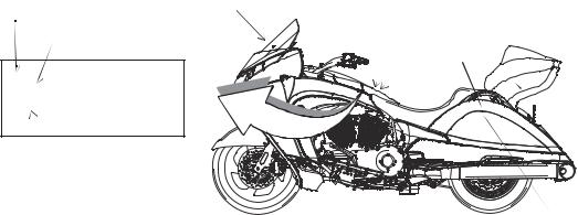
Safety
Safety and Information Labels
Labels are model-specific and market-specific. Your motorcycle may not contain all of the labels shown. See page 83 for seat removal instructions.
1.Windshield Label
2.Vehicle Identification Number (VIN) (on frame, under rear console cover)
3.Operator/Fuel Warning (on rear console cover)
4.Vehicle/Noise Emission Control Information (VECI/NECI) (inside left saddlebag)
5.Cargo Information (in saddlebags and trunk, if equipped)
|
Date of Manufacture |
1 |
|
|
GVWR Information |
||
|
2 |
||
|
VIN Number |
3 |
4
Tire & Wheel Information
GAWR Information
5
Reporting Safety Defects
If you believe that your vehicle has a defect that could result in a crash or cause injury or death, you should immediately inform the National Highway Traffic Safety Administration (NHTSA) in addition to notifying Polaris Industries in writing.
If NHTSA receives similar complaints, it may open an investigation, and if it finds that a safety defect exists in a group of vehicles, it may order a recall and remedy campaign. However, NHTSA cannot become involved in individual problems between you, your dealer or Polaris Industries.
To contact NHTSA, or obtain other information about motor vehicle safety, you may either call the Vehicle Safety Hotline toll-free at 1-888-327-4236 (TTY: 1-800-424-9153), visit the NHTSA website at www.safercar.gov, or write to:
ADMINISTRATOR, NHTSA
1200 New Jersey Avenue, SE
West Building
Washington, DC 20590
15
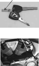
Identification
Ignition Key Number
The ignition key number is stamped on the small metal tag attached to the key ring. Remove the tag and record the number on page 107. Store the tag in a safe place.
Additional keys can be copied from one of the original keys. A VICTORY key blank is required. If you lose both original keys, you will need the following:
•Key number (recorded on page 107)
•A new key blank from a VICTORY dealer
•Proof of ownership
•A locksmith or VICTORY dealer with the equipment necessary to cut a new key
Engine Identification Number
The engine number is stamped into the right crankcase behind the rear cylinder. Record the number in the space provided on page 107.
16

Left Side View
1.Spark Plugs
2.Power Port
3.Front Brake Caliper
4.Gear Shift Pedal
5.Operator Footrest
6.Sidestand
7.Oil Drain Plug
8.Oil Filter
9.Passenger Footrest
10.Rear Brake Caliper
11.Diagnostic Connector (in saddlebag)
12.Running Light (Tour)
13.Rear Speakers (Tour)
14.Passenger Hand Grip
15.Rear Shock Air Fitting (under saddlebag door)
Right Side View
1.Drive Belt Guard
2.Drive Belt
3.Passenger Footrest
4.Drive Sprocket (under cover)
5.Speed Sensor (top of crankcase)
6.Engine Oil Fill Cap / Dipstick
7.Rear Brake Pedal
8.Operator Footrest
9.Front Brake Caliper
10.Passenger Hand Grip
11.Reflector
Identification
|
2 |
15 |
13 |
2 |
12 |
14
1
3
|
4 |
5 |
6 |
7 |
8 |
9 |
10 |
11 |
11 10
|
1 |
2 |
3 |
4 |
5 |
6 |
7 |
8 |
9 |
17
Identification
Top View
1.Windshield
2.Radio Antenna (under dash)
3.Mirror
4.Clutch Fluid Reservoir
5.Clutch Lever
6.Glove Compartment Door
7.Operator Seat
8.Passenger Seat
9.Saddlebag Latch
10.Trim Panel (if equipped)
11.Front Brake Lever
12.Front Brake Fluid Reservoir
13.Fuel Filler Cap Access Door
Front View
1.Front Turn Signal (outer light, each side)
2.Wind Deflector
3.Headlamp
4.Driving Lamp (or HID lamp if equipped)
5.Air Filter (front of frame)
6.Tiedown Loop (on frame)
7.Rear Brake Fluid Reservoir
8.Battery
9.Oil Cooler
10.Horn
11.Evaporative Emissions Canister
12.Fuel Tank (one each side)
13.Running Light (inner light, each side)
1
2
 3
3
3
 13
13
4
 12
12
5
 11
11
6
7
 9
9
8
9
 10
10
2
3


|
4 |
||
|
5 |
||
|
6 |
||
|
7 |
8 |
9 |
12
 11
11
 10
10
18
Rear View
1.Turn Signals (uppermost in lens)
2.Tail Lamps (3 each side)
3.Brake Lamps
4.Exhaust Mufflers
5.License Plate Bracket
Console
1.Speakers
2.Fuel Gauge
3.Speedometer
4.Indicator Lamp Display
5.Multi-Function Display
6.Tachometer
7.Volt Meter
8.Cruise Control Switches (if equipped)
9.Radio Controls
10.Left Handlebar Switch/ Audio Control
|
Identification |
|
|
1 |
|
|
2 |
|
|
5 |
|
|
3 |
|
|
4 |
4 |
|
3 |
5 |
|
2 |
7 |
|
1 |
1 |
|
8 |
|
|
10 |
9 |
19
Instruments, Features and Controls
Ignition Switch
Place the ignition key in the ignition switch to operate the following functions of the switch.
|
OFF |
All electrical circuits are off. The key can be removed. |
|
ON |
All electrical circuits are on. The ignition key cannot be removed. Headlamp, taillight, |
|
running lights, radio and instrument lights illuminate. Hazard flashers and turn signals |
|
|
can be activated. |
|
|
ACC |
Power is supplied to accessory circuits, radio, instruments, turn signals, brake light, |
|
windshield motor, horn and hazard (flasher). The key can be removed. |
|
|
LOCK |
All electrical circuits are off. The fuel door and glove compartment are locked when |
|
the steering is locked. The key can be removed. See page 20 for instructions. |
FUEL DOOR See page 21 for instructions.
Ignition Key
The ignition key operates the ignition switch, fuel door, saddlebag door locks and trunk door lock (if equipped). Read the engine starting procedures beginning on page 49 before starting the engine. Store the spare key in a safe place separate from the main key.
Tip: Use a key ring that won’t scratch the finish on the console.
Ignition Lock
Use the ignition lock feature to lock the steering. When locked, the key can be removed.
Tip: The fuel door and glove compartment are locked when the steering is locked.
1.Turn the handlebars full left.
2.Turn the key to the OFF position.
3.Push the key down while moving it counter-clockwise
|
to the LOCK position. |
Locked |
|
4. Release the key. |
20
Instruments, Features and Controls
Ignition Switch
Fuel Door Lock
1.Turn the handlebars full left.
2.Turn the key to the OFF position.
Tip: Do not push the key down when unlocking the fuel door.
3.Turn the ignition key counter-clockwise to release the fuel door latch. The door will open under light spring tension. See page 48 for fueling procedure.
4.Remove the fuel cap and place it in the cap holder while fueling. Reinstall the fuel cap securely before closing the fuel door.
5.Close the fuel door and press downward to engage the latch.
Tip: The fuel door and glove compartment are locked when the steering is locked.
Fuel
Door
Release
Fuel
Door
Cap
Holder 
21
Instruments, Features and Controls
Instrument Cluster
The instrument cluster includes the speedometer, tachometer, fuel gauge, volt meter, indicator lamps and multi-function display.
|
Indicator Lamps |
|||||||||||||||||||||||||||
|
Speedometer |
Tachometer |
||||||||||||||||||||||||||
Multi-Function Display
Speedometer
The speedometer displays vehicle speed in either miles per hour or kilometers per hour. See page 25.
Tachometer
The tachometer displays engine speed in revolutions per minute (RPM). A red line on the face of the gauge indicates the maximum safe engine speed.
WARNING! Excessive engine speed can cause engine damage or failure, which could result in serious injury or death. Do not allow engine speed to exceed the red line.
Fuel Gauge
The fuel gauge displays fuel level. The key must be in the ON or ACC position. For the most accurate reading, sit on the motorcycle and bring it to the upright position.
Volt Meter
When the key is in the ON position, the volt meter displays battery voltage. If the engine is not running, approximate battery voltage displays. If the engine is running, approximate charging voltage displays.
22
Instruments, Features and Controls
Indicator Lamps
|
Anti-Lock |
||
|
Brake System (ABS) |
||
|
High Beam |
(if equipped) |
Right Turn |
|
Left Turn |
Low Fuel |
 Oil Pressure
Cruise Control
|
Check Engine |
Battery Warning |
||
|
Neutral |
|||
|
Lamp |
Indicates |
Condition |
|
|
Neutral |
This lamp illuminates when the transmission is in neutral and the ignition |
||
|
key is in the ON or ACC position. |
|||
|
High Beam |
This lamp illuminates when the headlamp switch is set to high beam. |
||
|
Check Engine |
This lamp illuminates momentarily when the ignition switch is in the ON |
||
|
position and the engine is off. This indicates proper function. If this lamp |
|||
|
illuminates while the engine is running, contact an authorized VICTORY |
|||
|
dealer promptly for diagnosis. The light will remain on if the tilt sensor |
|||
|
shuts down the engine. See page 28. If abnormal sensor or engine |
|||
|
operation is detected the light will remain on as long as the fault |
|||
|
condition exists. Retrieve the error codes for diagnosis. See page 25. |
|||
|
This lamp is also known as a malfunction indicator lamp (MIL). |
|||
|
Turn Signal |
One arrow flashes when the corresponding turn signal is activated. Both |
||
|
arrows flash when the hazard signal is activated. If a bulb fails, or if there |
|||
|
is a short circuit in the signal system, the lamp flashes at more than |
|||
|
twice the normal rate. |
|||
|
Low Oil |
This lamp illuminates when the ignition switch is in the ON position and |
||
|
Pressure |
the engine is off, indicating that the indicator circuit is functioning |
||
|
properly. This lamp also illuminates if engine oil pressure drops below |
|||
|
safe operating pressure. If this lamp illuminates while the engine is |
|||
|
running, turn the engine off as soon as safely possible and check the oil |
|||
|
level. If the oil level is correct and the lamp remains on after the engine is |
|||
|
restarted, turn the engine off immediately. |
23
Instruments, Features and Controls
Indicator Lamps
|
Lamp |
Indicates |
Condition |
|
Low Fuel |
This lamp illuminates when approximately one gallon (3.8 liters) of fuel |
|
|
remains in the fuel tank. |
||
|
Low Battery |
This lamp illuminates when battery voltage is low. Make sure the |
|
|
Warning |
charging system is operating properly. See page 93. |
|
|
Cruise Control |
Before using the cruise control, read the safety and operation |
|
|
Engaged |
procedures beginning on page 52. |
|
|
Anti-Lock Brake |
The ABS indicator always illuminates when the key is in the ON position |
|
|
System Not |
and remains on until the anti-lock system activates, which occurs when |
|
|
Activated |
vehicle speed exceeds 6 MPH (10 km/h). When the lamp is illuminated, |
|
|
(if equipped) |
the anti-lock brakes will not activate, but the conventional brake system |
|
|
will continue to operate normally. |
Multi-Function Display
Use the mode button to toggle through the modes of the multi-function display. See page 28. Modes available include:
•clock
•gear position
•ambient temperature
•odometer/trip odometer
•fuel range
•average fuel consumption rate
•fuel economy
•trip time (and other trip information)
Clock
Gear 

Position
|
Odometer |
Temperature |
|
|
Trip Odometer |
||
24
Instruments, Features and Controls
Multi-Function Display
Engine Error Codes
The error screen displays only when the CHECK ENGINE light is on or when it goes on and off during one ignition cycle. Error codes are not stored. When the key is turned OFF, the code and message is lost, but will reappear if the fault reoccurs after restarting the engine.
If the CHECK ENGINE indicator lamp illuminates, retrieve the error codes from the display.
1.If the error codes are not displayed, use the mode button to toggle until «Err» displays in the clock area.
2.Record the three code numbers displayed in the gear position, temperature and odometer displays.
|
Error Code |
Failure Mode |
|
Number (0-9) |
Indicator (FMI) |
“Err” 88:888188 F
C
|
Avg |
Speed Range Inst |
Time |
|
|
TRIP 2 |
88:88: 88. |
miles / gal |
|
|
TRIP 1 |
km / h |
Suspect Parameter Number (SPN)
3. See an authorized VICTORY dealer for code details and diagnosis.
Display Units (Standard/Metric)
The display can be changed to display either standard or metric units of measurement.
Tip: To exit the set-up mode at any time, wait 10 seconds.The display automatically exits and returns to the odometer display.
|
Standard Display |
Metric Display |
|||
|
Distance |
Miles |
Kilometers |
||
|
Fuel |
U.S. Gallons |
I = Imperial Gallons |
Liter = Liters |
|
|
Temperature |
Fahrenheit |
Celsius |
||
|
Time |
12-Hour Clock |
24-Hour Clock |
Display Units (Standard/Metric)
1.Turn the key to the OFF position.
2.Press and hold the mode button while turning the key to the ON or ACC position.
3.When the display flashes the distance setting, tap the mode button to advance to the desired setting.
4.Press and hold the mode button to save the setting and advance to the next display option.
5.Repeat the procedure to change remaining display settings.
25
Instruments, Features and Controls
Multi-Function Display
Clock
Tip: The clock must be reset any time the battery has been disconnected or discharged.
1. Turn the key to ON or ACC. Use the mode button to toggle to the odometer display.
Tip: If LOW FUEL is flashing, the display will not enter the CLOCK SET mode.
2.Press and hold the mode button until the hour segment flashes. Release the button.
3.With the segment flashing, tap the mode button to advance to the desired setting.
4.Press and hold the mode button until the next segment flashes. Release the button.
5.Repeat steps 3-4 twice to set the 10-minute and 1-minute segments. After completing the 1-minute segment, step 4 will save the new settings and exit the clock mode.
6.Turn the key to the OFF position.
Odometer/Trip Odometer
The odometer displays the total distance traveled by the vehicle. The trip odometer displays distance traveled since the trip odometer was reset. To view the trip odometer, turn the key to the ON position. Use the mode button to toggle to the trip odometer.
To reset the trip odometer, toggle to the trip odometer, then press and hold the mode button until the trip odometer resets.
Gear Position
Gear position displays only when the vehicle is moving and the clutch is engaged. If the vehicle stops moving, or if the clutch is disengaged, “—” will show in the display.
Temperature
The key must be in the ON or ACC position to display ambient air temperature.
26
![]()
Instruments, Features and Controls
Console Switches
High
Off
Low
On
Off
On
Off
|
Hand Grip |
Optional |
|
|
Accessory |
||
|
Heater Switch |
||
|
Switch |
||
|
Hazard Switch |
||
|
Driving Lamp |
||
|
Switch |
Hand Grip Heater Switch
Press the top (high heat) or bottom (low heat) of the rocker switch to turn the hand grip heaters on. Move the switch to the center position to turn the heaters off.
Hazard Switch/Emergency Flashers
All turn signals flash when the emergency flashers are activated. Press the top of the hazard switch to turn the flashers on. Press the bottom of the switch to turn the flashers off.
Driving Lamp Switch
The driving lamp is an additional low beam lamp not controlled by the headlamp high/low switch. This lamp is a center headlamp (or HID lamp, if equipped). The ignition key must be on to use the driving lamp. Press the top of the rocker switch to turn the light on. Press the bottom of the switch to turn the light off.
27

Instruments, Features and Controls
Seat Heater Switches
Seat heater switches (if equipped) are located on the seat under the left passenger hand grip. The low heat setting is adequate for most conditions. Use the high heat setting with caution.
•The front switch controls the driver’s seat heater.
•The rear switch controls the passenger’s seat heater.
Tilt Sensor
A tilt sensor stops the engine if the motorcycle tips beyond 45 degrees to one side. The check engine light will also illuminate. To restart the engine, cycle the ignition switch to the OFF position, wait 10 seconds, then restart the engine.
Mode Button
The mode button is located on the front side of the left handlebar switch. Use the mode button to toggle through the modes of the multi-function display. See page 24. Use the mode button to set the display units to either standard or metric units of measurement. See page 25.
Tip: If “Err” displays while toggling through the features, a system error has been logged. See page 25.
Mirrors
Adjust the rear view mirrors by applying light pressure at the outer edges of the mirror.
28

Instruments, Features and Controls
Headlamp Switch (High/Low)
The headlamp switch is located on the left handlebar. Use the switch to toggle the headlamp to high beam or low beam. The key must be in the ON or ACC position.
Tip: To turn the headlamp on, turn the ignition key to ON and tap or press the start switch.
•Press the top of the switch to activate high beam.
•Press the bottom of the switch to activate low beam.
Horn Switch
The horn switch is located on the left handlebar. Press the horn switch to sound the horn. The key must be in the ON or ACC position.
Windshield Adjustment Switch
The motorized windshield adjustment switch (if equipped) is located on the left handlebar. Use the switch to change the height and angle of the windshield. The key must be in the ON or ACC position.
Tip: Do not continuously cycle the windshield switch more than once in a 60-second period.
•Press the top of the switch to raise the windshield.
•Press the bottom of the switch to lower the windshield.
For models not equipped with this feature, use the manual windshield adjustment procedure. See page 35.
Horn Switch
Raise
Windshield
29

Instruments, Features and Controls
Turn Signal Switch
The turn signal switch is located on the left handlebar. Use the switch to activate a turn signal. The key must be in the ON or ACC position.
•Push the switch to the left to activate the left turn signals.
•Push the switch to the right to activate the right turn signals.
Turn signals automatically cancel after predetermined speed and distance conditions are met. To manually cancel a signal, move the switch to the center position and press it inward.
Tip: The momentary signal feature is useful when passing or changing lanes. To use the momentary feature, push and hold the switch through at least one complete flash cycle (at least one second) to activate the feature. The signal will then cancel the moment the switch is released.
Clutch Lever
The clutch lever is located on the left handlebar. Disengage the clutch before shifting gears. For smooth clutch operation, pull the lever quickly and release it gradually.
• To disengage the clutch, pull the lever toward the handlebar.
|
• To engage the clutch, gradually release the |
Interlock |
Clutch |
|
lever. |
||
|
Switch |
Lever |
Starter Interlock Switch
The starter interlock switch is located on the left handlebar. This switch prevents the electric starter from operating when the transmission is in gear and the clutch is engaged (lever released). Read the engine starting procedures beginning on page 49 before starting the engine.
WARNING! Never start the engine with the transmission in gear and the clutch disengaged unless you are properly seated with the front brake applied.
30

Instruments, Features and Controls
Engine Starter Switch
The starter switch is located on the right handlebar. Use the starter switch to start the engine, turn the headlights on and operate in reverse (if equipped). The switch will operate only when the engine stop/run switch is in the RUN position and the transmission is in neutral (or the clutch is disengaged). The reverse lever (if equipped) must also be disengaged.
Tip: If the reverse system fuse has blown, the starter switch will not function even if the reverse lever is disengaged. Replace the fuse. See page 89.
Read the engine starting procedures before starting the
engine. See page 49.
Engage Starter
• Press the right side of the starter switch to engage the starter motor.
• Tap the starter switch to turn the headlight on without starting the engine.
• See page 55 for reverse operation.
|
Engine Stop/Run Switch |
Run |
Stop |
The engine stop/run switch is located on the right handlebar. This switch completes or interrupts the ignition, starter and fuel pump circuits. Use the engine stop/run switch to turn the engine off quickly. Turn the key off after the engine stops.
•Press the bottom of the switch (RUN) to complete the circuits and allow the engine to start and run.
•Press the top of the switch (STOP) to interrupt the cir-
cuits and stop the engine. The engine should not start or run when the switch is in the STOP position.
31

Instruments, Features and Controls
Throttle Control Grip
The throttle control grip is located on the right handlebar. Use the throttle control grip to control engine speed. While seated in the proper riding position:
•Rotate the top of the grip rearward to increase engine speed and power.
•Rotate the top of the grip forward to decrease engine speed and power.
Decrease
 Speed
Speed
Increase
Speed
Brakes
Linked Braking System
The front and rear brakes on the motorcycle are linked. The front brake lever activates only the front brake calipers. The rear brake pedal activates the rear brake caliper fully while simultaneously activating one of the three pistons in each front brake caliper.
For maximum brake effectiveness, apply the front brake lever and the rear brake pedal together, as with a conventional (non-linked) brake system.
Anti-Lock Brake System (ABS)
This system is a linked brake system. The anti-lock brake system automatically reduces or increases brake pressure as needed to provide optimum braking control, reducing the chance of wheel lock-up during hard braking events or when braking on rough, uneven, slippery or loose surfaces. See page 8.
•The anti-lock brake system cannot be turned off.
•The ABS indicator always illuminates when the key is in the ON or ACC position and remains on until the anti-lock system activates, which occurs when vehicle speed exceeds 6 MPH (10 km/h).
•When the lamp is illuminated, the anti-lock brakes will not activate, but the conventional brake system will continue to operate normally.
•When the anti-lock brakes engage during a braking event, the rider will feel pulsing at the brake levers. Continue to apply steady pressure to the brakes for the best stopping performance.
•Service the indicator lamp if the ABS light does not come on when the key is turned to the ON or ACC position. See your authorized VICTORY dealer for this service.
•If the lamp continues to illuminate after vehicle speed exceeds 6 MPH (10 km/h), the ABS system is not functioning. See your VICTORY dealer promptly for service.
32

Instruments, Features and Controls
Brakes
Anti-Lock Brake System (ABS)
•Operating with non-recommended tires or improper tire pressure may reduce the effectiveness of the anti-lock brake system. Always use the recommended size and type of tires specified for your vehicle. Always maintain the recommended tire pressure.
•The anti-lock brake system will not prevent wheel lockup, loss of traction or loss of control under all conditions. Always adhere to all safe motorcycle-riding practices as recommended.
•It is not unusual to leave tire marks on the road surface during a hard braking event.
•The anti-lock brake system does not compensate for or reduce the risks associated with:
•excessive speed
•reduced traction on rough, uneven or loose surfaces
•poor judgment
•improper operation
Front Brake Lever
The front brake lever is located on the right handlebar. This lever controls only the front brakes. The front brakes should be applied simultaneously with the rear brakes.
To apply the front brake, pull the lever toward the handlebar.
See page 51 for braking procedures.
Front brake lever reach (distance to the hand grip) is adjustable.
1.Pull and hold the lever away from the hand grip.
2.To increase reach distance, rotate the adjuster to align a lower number with the arrow on the lever.
3.To decrease reach distance, rotate the adjuster to align a higher number with the arrow on the lever.
Front Brake Lever
Pull and hold lever
Adjuster
 Numbers
Arrow on Lever
33

Instruments, Features and Controls
Brakes
Rear Brake Pedal
The rear brake pedal is located on the right side of the motorcycle. Press downward on the rear brake pedal to apply the rear brake.
The rear brake pedal activates the rear brake caliper fully while simultaneously activating one of the three pistons in each front brake caliper.
|
See page 35 for pedal adjustment options. |
|
|
See page 51 for braking procedures. |
Rear Brake Pedal |
Gear Shift Pedal
The gear shift pedal is located on the left side of the motorcycle.
• Press downward on the gear shift pedal to shift to a lower gear.
• Lift up on the gear shift pedal to shift to a higher gear.
See page 35 for pedal adjustment options. See pages 50-51 for gear shifting procedures.
Gear Shift Pedal
34

Instruments, Features and Controls
Pedal Adjustment
The brake pedal and gear shift pedal controls can be adjusted to a front, rear or center position. The center position is the factory setting.
Tip: An accessory linkage rod is needed to fully adjust the gear shift pedal control.
1. Remove the screw from the footwell support.
Tool: 6 mm Allen wrench
2.Slide the control forward or rearward in its track until the threaded hole of the control aligns with the desired hole in the footrest support.
3.Reinstall the screw.
Torque: 96 in-lbs (11 Nm)
4.After adjusting the shift pedal, always readjust the shift linkage rod. Loosen both jam nuts on the linkage and turn the shaft until the footpeg is about 90 mm from the floorboard (or to desired height). Tighten both jam nuts.
Torque: 96 in-lbs (11 Nm).
Windshield Adjustment
Use the motorized windshield adjustment switch (if equipped) to adjust the windshield. See page 29. If the motorcycle is not equipped with this feature, you can manually adjust the windshield.
1.Park the motorcycle on a firm, level surface. Turn the key to the OFF position.
2.Remove the windshield trim panel. See page 83.
3.Remove the retaining clip.
4.Hold slight downward pressure on the bottom of the windshield (it is under slight upward spring pressure). Remove the clevis pin.
5.Slide the windshield inner bracket to align with one of the optional holes in the outer bracket. Reinstall the clevis pin. Reinstall the retaining clip in the clevis pin.
6.Reinstall the windshield trim panel.
Center Adjustment
Position
Retaining Clip
Clevis Pin
35

Instruments, Features and Controls
Glove Compartment
Before opening the glove compartment, turn the handlebars slightly to the right.
1.Press and release the inner edge of the compartment door. The door will open under light spring tension.
2.To close the glove compartment door, press the inner edge of the door downward firmly to secure the latch.
3.To lock the glove compartment door, turn the ignition key to the LOCK position.
Tip: The fuel door and glove compartment are locked when the steering is locked.
Sidestand
The sidestand is located on the left side of the motorcycle.
WARNING! An improperly retracted sidestand could contact the ground and cause a loss of control resulting in serious injury or death. Always retract the sidestand fully before
operating the motorcycle.
To park the motorcycle, swing the end of the sidestand downward and away from the motorcycle until it is fully extended. Lean the motorcycle to the left until the sidestand firmly supports the motorcycle.
To retract the sidestand, straddle the motorcycle and bring it to the fully upright position. Swing the end of the sidestand upward and toward the motorcycle until it is fully retracted.
Saddlebag and Trunk Door Locks
Use the ignition key to lock and unlock the trunk and saddlebag doors. The doors should be locked before riding.
To lock a door, place the key in the lock and turn it coun- ter-clockwise. To unlock a door, turn the key clockwise.
After unlocking a door, press the door lock to release the latch and open the door.
Refer to the Gross Vehicle Weight Rating information beginning on page 14 for loading information.
36
![]()
|
Radio/Audio Systems |
Instruments, Features and Controls |
|
Radio Panel |
Refer to the Audio System section of this manual (beginning on page 111) for radio and accessory audio systems operation.
Tool Kit
The tool kit can be used to perform most basic maintenance items. Tools provided in the tool kit include:
1.4 mm Ball Drive Allen Wrench
2.4 mm / 6 mm Open End Wrench
3.6 mm Ball Drive Allen Wrench
4.8 mm / 10 mm Open End Wrench
5.Combination Phillips / Slot Screw Driver
6.Rear Shock Absorber / Tire Pressure Gauge
7.Fuse Puller
37
Pre-Ride Inspections
To keep your motorcycle in safe operating condition, always perform the recommended preride inspections before each ride. This is especially important before making a long trip and when removing the motorcycle from storage.
WARNING! Failure to perform the recommended pre-ride inspections could result in component failure while riding, which could result in serious injury or death. Always perform the pre-ride inspections before each ride. When inspection reveals the need for adjustment, replacement or repair, perform the service promptly.
You must be familiar with all instruments and controls to perform the pre-ride inspections.
Tip: During the pre-ride inspections you may use products that are potentially hazardous, such as oil or brake fluid. When using any of these products, always follow the instructions and warnings on the product packaging.
When inspections reveal the need for adjustment, replacement or repair:
•refer to the maintenance section of this manual
•refer to the service manual
•or see your authorized VICTORY dealer
38
 Loading…
Посмотреть инструкция для Victory Vision Tour (2017) бесплатно. Руководство относится к категории мотоциклы, 3 человек(а) дали ему среднюю оценку 9.4. Руководство доступно на следующих языках: английский. У вас есть вопрос о Victory Vision Tour (2017) или вам нужна помощь? Задайте свой вопрос здесь
Не можете найти ответ на свой вопрос в руководстве? Вы можете найти ответ на свой вопрос ниже, в разделе часто задаваемых вопросов о Victory Vision Tour (2017).
Как перевести мили в километры?
1 миля равна 1,609344 километрам, а 1 километр — 0,62137119 милям.
В чем разница между топливом E10 и E5?
В топливе E10 содержится до десяти процентов этанола, в то время как в E5 содержится менее пяти процентов. Соответственно, топливо E10 менее вредит окружающей среде.
Какова рекомендуемая частота замены масляного фильтра в двигателе Victory?
В большинстве двигателей масляный фильтр необходимо менять через каждые 6000 километров (около 4000 миль).
Как часто следует менять масло в двигателе Victory?
В большинстве двигателей масло необходимо менять через каждые 6000 километров (около 4000 миль).
Как удалить ржавчину с устройства Victory мотоцикл?
1. Замочите поржавевшую деталь в уксусе, пока ржавчина не размокнет полностью. 2. Обрабатывайте ржавчину уксусом в течение 24 часов. 3. Удалите ржавчину с помощью металлической щетки или алюминиевой фольги.
Инструкция Victory Vision Tour (2017) доступно в русский?
К сожалению, у нас нет руководства для Victory Vision Tour (2017), доступного в русский. Это руководство доступно в английский.
Не нашли свой вопрос? Задайте свой вопрос здесь