- Manuals
- Brands
- BRP Manuals
- Snowmobiles
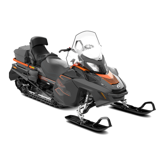
- Lynx REV-XU Series
- Operator’s manual
-
Contents
-
Table of Contents
-
Troubleshooting
-
Bookmarks
Quick Links
2019
REV-XU
TM
Series
Read this guide thoroughly.
It contains important safety information.
Minimum recommended operator’s age: 16 years old.
Keep this Operator’s Guide in the vehicle.
6 1 9
9 0 0
9 6 9
Original Instructions
Related Manuals for BRP Lynx REV-XU Series
Summary of Contents for BRP Lynx REV-XU Series
-
Page 1
2019 REV-XU Series Read this guide thoroughly. It contains important safety information. Minimum recommended operator’s age: 16 years old. Keep this Operator’s Guide in the vehicle. 6 1 9 9 0 0 9 6 9 Original Instructions… -
Page 2
©… -
Page 3
® ROTAX ® Lynx ® D.E.S.S.™ TRA™ XU™ HPG™ PPS™ 619900969 en COJT ®™ and the BRP logo are trademarks of Bombardier Recreational Products Inc. or its affiliates. ©2018 Bombardier Recreational Products Inc. and BRP US Inc. All rights reserved. -
Page 4: Foreword
Bombardier Recreational Products of your snowmobile as well as com- Inc. (BRP) warranty and a network of pleted the final adjustment required to authorized Lynx snowmobile dealers suit your specific weight and riding en-…
-
Page 5: Know Before You Go
BRP reserves The safety alert symbol indicates a the right at any time to discontinue or potential injury hazard.
-
Page 6
FOREWORD This Operator’s Guide should remain with the vehicle when it’s sold. _______________… -
Page 7: Table Of Contents
Installation of Studs on BRP Approved Tracks ……. . 28…
-
Page 8
TABLE OF CONTENTS CONTROLS, INSTRUMENTS AND EQUIPMENT (cont’d) Gearshift Lever …………. . . 49 9) Adjustable Mirrors.
 -
Page 9
TABLE OF CONTENTS OPERATING MODES (900 ACE AND 1200 4-TEC)……78 ECO Mode (Fuel Economy Mode) . -
Page 10
® BRP FINLAND OY INTERNATIONAL LIMITED WARRANTY: 2019 LYNX SNOWMOBILES …………..160 MAINTENANCE RECORDS . -
Page 11
TABLE OF CONTENTS _______________… -
Page 12: Safety Information
SAFETY INFORMATION ________ ________ SAFETY INFORMATION…
-
Page 13: General Precautions
Do not make unauthorized modifica- tions, or use attachments or acces- To prevent serious injury or death from sories that are not approved by BRP. carbon monoxide: Since these changes have not been – Never run the vehicle in poorly ven-…
-
Page 14: Special Safety Messages
– BRP recommends the operator has at least 16 years old of age. – It is very important to inform any operator, regardless of his experience, of the handling characteristics of this snowmobile.
-
Page 15
SPECIAL SAFETY MESSAGES – Speeding can be fatal. In many cases, you cannot react or respond quickly enough to the unexpected. Always ride at a speed which is suitable to the trail, weather conditions and your own ability. Know your local rules. Speed limit may be in effect and meant to be observed. -
Page 16
– You may stud the track on this vehicle model. However, you MUST only use the BRP approved type stud for use on Lynx snowmobiles. DO NOT EVER use con- ventional studs, the track thickness is thinner compared to some other tracks. -
Page 17: Active Technologies (Itc) (900 Ace And 1200 4-Tec)
ACTIVE TECHNOLOGIES (iTC) (900 ACE AND 1200 4-TEC) Introduction Sport Mode NOTE: Some functions or features de- In sport mode, maximum engine scribed in this section may not apply to power is available throughout the en- every model, or may be available as an gine operational range.
-
Page 18: Riding The Vehicle
RIDING THE VEHICLE Each operator has a responsibility to Before Starting the Engine ensure the safety of other recreation- 1. Remove snow and ice from body in- ists or bystanders. cluding lights, seat, footrests, con- You are responsible for proper opera- trols and instruments.
-
Page 19
RIDING THE VEHICLE 2. Check the engine cut-off switch (by 3. Release parking brake. pulling tether cord cap) and emer- WARM UP 4. Refer to the section and gency engine stop switch opera- follow instructions. tion. Pre-Ride Check List ✔ ITEM OPERATION Body including seat, footrests,… -
Page 20: How To Ride
RIDING THE VEHICLE How to Ride First aid kit Provided tool kit Mobile phone Knife Riding Gear Proper snowmobile clothing should Flashlight Spare spark plugs be worn. It should be comfortable Friction tape Trail map and not too tight. Always check the weather forecast before going on a Spare drive belt Snack…
-
Page 21
RIDING THE VEHICLE Sitting Feet on the running boards, body mid- way back on seat is an ideal position when operating the snowmobile over familiar, smooth terrain. Knees and hips should remain flexible to absorb shocks. fmo2008-003-003 Standing Place both feet on the running boards. Knees should be flexed to absorb the shock from surface bumps. -
Page 22: Carrying A Passenger
BRP recommends that the the vehicle. In addition, “body eng- child sits in the center location. This lish”…
-
Page 23: Terrain/Riding Variations
RIDING THE VEHICLE Deep Snow WARNING In deep “powder” snow, your vehicle When riding with a passenger: could begin to “bog” down. If this oc- – Braking ability and steering curs, turn in as wide an arc as possible control are reduced. Decrease and look for a firmer base.
-
Page 24
RIDING THE VEHICLE yourself plenty of room for stopping If a higher than safe speed is reached, and turning. This is especially true at slow down by braking but apply the night. brake with frequent light pressure. Never jam the brake and lock the track. Hard Packed Snow Side Hill Don’t underestimate hard packed… -
Page 25
RIDING THE VEHICLE Here are some web sites that can help Unseen Obstruction you finding important information: There may be obstructions hidden – Europe: www.avalanches.org beneath the snow. Driving off es- tablished trails and in the woods re- Slush quires reduced speed and increased vigilance. -
Page 26
RIDING THE VEHICLE surfaces, “body english” is the key to snowmobile is no match for a train. turning. Leaning towards the inside of Before crossing a railroad track, stop, the turn and positioning body weight look and listen. on the inside foot will create a “bank- ing”… -
Page 27: Environment
RIDING THE VEHICLE Signals ture of our sport. Help us lead it down the right path! From all of us at BRP, If you intend to stop, raise either hand thank you for doing your share. straight above your head. A left turn is…
-
Page 28
RIDING THE VEHICLE Light Treading in no way suggests you Respecting the areas where we ride… should curb your appetite for snowmo- wherever they may be… is the only biling fun! It simply means tread with way to ensure their future enjoyment. respect! That’s one major reason why we know you’ll agree that Light Treading is smart… -
Page 29: Traction Enhancing Products
BRP for special studs installation. adaptation period. If your snowmobile is equipped with traction enhancing products, be sure to take plenty of time…
-
Page 30: Acceleration
TRACTION ENHANCING PRODUCTS Acceleration Using studs on the track will allow your sled to accelerate better on packed snow and ice but will have no notice- able effect on soft snow. This can cause sudden variations in traction under certain conditions. WARNING A33A31A To prevent surprises that could…
-
Page 31: Important Safety Rules
The use of traction enhancing products To ensure safe and proper installation, can increase the load and the stress on BRP recommends to have the studs in- certain snowmobile components, as stalled by your dealer. well as the vibration level. This can –…
-
Page 32: Inspection Of A Studded Track
TRACTION ENHANCING PRODUCTS – Lugs that are broken or torn off, ex- WARNING posing portions of rods – See an authorized Lynx dealer – Delamination of the rubber for current specific studding – Broken rods availability and applications. – Broken studs (studded tracks) –…
-
Page 33: Important On-Product Labels
IMPORTANT ON-PRODUCT LABELS Hang Tag Vehicle Safety Labels Read and understand all the safety la- bels on your vehicle. These labels are affixed to the vehicle for the safety of Dear consumer, the operator, passenger or bystander. Your new E-TEC engine technology has an automatic computer- r — controlled break-in period that ensures you get the most The following labels are on your vehicle performance, efficiency and reliability for the life.
-
Page 34
IMPORTANT ON-PRODUCT LABELS Label 1 Label 2 WARNING – Locate and read operator’s guide. Improper snowmobile use can result in SEVERE IN- JURY or DEATH. Follow all in- structions and warnings. – Always wear ear protection. – Never use with drugs or alcohol. 516009225 EN-516009225-DEC LABEL 2… -
Page 35
IMPORTANT ON-PRODUCT LABELS Label 4 L L abel 6 WARNING Beware of rotating parts. 516006873 COMMANDER GT AND 69 RANGER SNOWCRUISER MODELS — LABEL 6 L L abel 7 516006900 en ON PULLEY GUARD — LABEL 7 Label 8 WARNING –… -
Page 36
— Check oil level using the dipstick. — The engine of this snowmobile has been developed and validated using the BRP XPS Synthetic 4-stroke oil ( 293 600 112 ). BRP recommends the use of its XPS approved lubricant or equivalent. -
Page 37
IMPORTANT ON-PRODUCT LABELS Label 12 Label 13 WARNING Beware of rotating track •Read and understand all safety labels, locate and read operator’s guide and watch the safety video (using the QR code link or visit Ski-Doo web site) before operation. •Get familiar with your vehicle. -
Page 38: Technical Information Labels
IMPORTANT ON-PRODUCT LABELS Technical Information Labels Always electrically disconnect both fuel injectors prior to testing for ignition spark. Otherwise, fuel vapors may ignite in presence of a spark creating a fire hazard. 5583A 516005583A ON FUEL INJECTORS — E-TEC MODELS fmo2014-005-007_a fmo2014-003-008_a mmo2013-004-046_a…
-
Page 39
BRP recommends the use of its XPS approved lubricant or equivalent. Damages caused by oil which is not suitable for this engine may not be covered by the BRP limited warranty. See the operator’ s guide. 516007443 516007443 2-TEC- MODELS — ON ENGINE… -
Page 40
IMPORTANT ON-PRODUCT LABELS 516004294 ON CONSOLE NEAR SHIFT LEVER 516005672 ON CONSOLE — ALL COMMANDER AND 69 RANGER 900 ACE- MODELS DEC 513033943 EN-FR LOCATED ON FUEL CAP ________ ________ SAFETY INFORMATION… -
Page 41
IMPORTANT ON-PRODUCT LABELS This page is intentionally blank _______ ________ SAFETY INFORMATION… -
Page 42: Vehicle Information
VEHICLE INFORMATION _______________…
-
Page 43: Controls, Instruments And Equipment
CONTROLS, INSTRUMENTS AND EQUIPMENT NOTE: Some features may not apply to your model or could be optional. NOTE: Some vehicle safety labels are not shown on illustrations. For information VEHICLE SAFETY LABELS on vehicle safety labels, refer to fmo2014-003-033_a TYPICAL — ALL MODELS EXCEPT 69 RANGER ALPINE ______________…
-
Page 44
CONTROLS, INSTRUMENTS AND EQUIPMENT fmo2013-006-001_d TYPICAL — 69 RANGER ALPINE MODELS ONLY fmo2013-003-002_a TYPICAL — ALL MODELS EXCEPT 69 RANGER ALPINE _______________… -
Page 45
CONTROLS, INSTRUMENTS AND EQUIPMENT fmo2016-006-002_c TYPICAL — 69 RANGER ALPINE MODELS ONLY fmo2016-002-003_b COMMANDER GRAND TOURER 1200 4-TEC, 900 AND COMMANDER LIMITED 600 E-TEC fmo2012-003-016_b COMMANDER LIMITED 600 E-TEC AND 69 RANGER ARMY LTD fmo2014-003-004_a COMMANDER GRAND TOURER 1200 4-TEC AND 900 ECS²… -
Page 46: Handlebar
CONTROLS, INSTRUMENTS AND EQUIPMENT mmo2015-008-002_38 mmo2008-008-011_b TYPICAL — LH SIDE OF FUEL TANK — 900 ACE TYPICAL AND 1200 4-TEC 1. Throttle lever 2. To accelerate 1) Handlebar 3. To decelerate The handlebar controls the steering WARNING of the snowmobile. As the handlebar Test the throttle lever operation is rotated to right or left, the skis are each time before starting the en-…
-
Page 47: Brake Lever
CONTROLS, INSTRUMENTS AND EQUIPMENT WARNING Test the throttle lever operation each time before starting the en- gine. The lever must return to its the rest position once released. Otherwise, do not start engine. Switching from Thumb to Finger Throttle Position mmo2015-008-100_a CAUTION It is highly recom- IF WANTED, CONTINUE TO ROTATE THE…
-
Page 48: Parking Brake Lever
CONTROLS, INSTRUMENTS AND EQUIPMENT mmo2014-004-001_a mmo2009-005-006_a TYPICAL 1. Brake lever TYPICAL — ENGAGE MECHANISM 2. To apply brake Step 1: Apply and hold regular brake Step 2: Lock brake lever using parking brake lever 4) Parking Brake Lever Parking brake lever is located on the LH To Release Parking Brake side of handlebar.
-
Page 49: Emergency Engine Stop Switch
CONTROLS, INSTRUMENTS AND EQUIPMENT RF D.E.S.S. (Digitally Encoded The Lynx learning key, limits the speed Security System) of the snowmobile and the engine torque, therefore enabling first time The tether cord cap has an integrated users and less experienced operators D.E.S.S.
-
Page 50: Multifunction Switch
CONTROLS, INSTRUMENTS AND EQUIPMENT mmo2016-008-201_a ON POSITION fmo2014-003-003_a All operators of the snowmobile 1. Start button should familiarize themselves with the 2. Headlights dimmer switch function of the emergency engine stop 3. Heated grips switch by using it several times on first 4.
-
Page 51
CONTROLS, INSTRUMENTS AND EQUIPMENT Heated Grips Switch Heated Throttle Lever Switch fmo2014-003-003_c fmo2014-003-003_b TYPICAL TYPICAL 1. Heated throttle lever switch 1. Heated grips switch 2. Increase heat (Warmer) 2. Increase heat 3. Decrease heat (Colder) 3. Decrease heat NOTE: The heating intensity is dis- The heating intensity is displayed via played via the multifunction display the multifunction display. -
Page 52: Gearshift Lever
CONTROLS, INSTRUMENTS AND EQUIPMENT Mode/Set Button WARNING This button can be used instead of the Adjust with vehicle at rest in a safe two buttons on top of the analog/digital place. gauge to facilitate gauge adjustments. – When pressed left, it has the same 10) Tool Kit functions as the MODE (M) button.
-
Page 53: Front And Rear Bumpers
CONTROLS, INSTRUMENTS AND EQUIPMENT Models with an Under Seat Storage Box fmo2012-003-007_a TYPICAL 1. Rear bumper fmo2015-003-001_a NOTICE Do not use skis or ski han- TYPICAL dles to pull or lift snowmobile. 1. Tool kit 12) Gauge 11) Front and Rear Bumpers WARNING To be used whenever snowmobile re-…
-
Page 54
CONTROLS, INSTRUMENTS AND EQUIPMENT WARNING Never adjust or set functions on the multifunction gauge while rid- ing the vehicle, you could lose con- trol. The multifunction display is used to: – Display the WELCOME message on power up – Display the KEY recognition mes- sage mmo2008-007-017 –… -
Page 55
CONTROLS, INSTRUMENTS AND EQUIPMENT MONITORING SYS- See table below for usual pilot lamps information. Refer to for details on malfunction pilot lamps. PILOT LAMP(S) BEEPER MESSAGE DISPLAY DESCRIPTION 4 short Two stroke engine: Injection oil level is low. Stop vehicle beeps in a safe place then, replenish injection oil reservoir. -
Page 56
CONTROLS, INSTRUMENTS AND EQUIPMENT Gauge Features AVAILABLE INDICATIONS IN NUMERICAL DISPLAY 800R 1200 FUNCTIONS 600 E-TEC 900 ACE E-TEC 4-TEC A) Speedometer B) Engine RPM C) Odometer D) Trip meter “A” or “B” E) Trip hour meter F) Clock G) Fuel level H) Altitude N.A. -
Page 57
CONTROLS, INSTRUMENTS AND EQUIPMENT A) Speedometer Press the MODE (M) button to confirm selection or wait 5 seconds. addition analog type speedometer, vehicle speed can also be displayed via the multifunction display. Vehicle speed can be displayed on dis- play 1 or display 2. mmo2007-009-066_o B) Tachometer (RPM) In addition of the analog type tachome-… -
Page 58
CONTROLS, INSTRUMENTS AND EQUIPMENT mmo2007-009-066_n mmo2007-009-066_p 1. RPM mode 1. Trip meter (TRIP A/TRIP B) mode Press the MODE (M) button to confirm Press and hold the SET (S) button to re- selection or wait 5 seconds. set. NOTE: Resetting TRIP B mode will also reset TOTAL FUEL CONSUMP- TION. -
Page 59
CONTROLS, INSTRUMENTS AND EQUIPMENT H) Altitude Displays vehicle approximate altitude above sea level calculated from the barometric pressure. NOTE: Altitude displayed is rounded off every 100 meters (gauge set in metric) or 200 feet (gauge set in impe- rial units). mmo2007-009-066_k To display vehicle altitude, proceed as follows. -
Page 60
CONTROLS, INSTRUMENTS AND EQUIPMENT mmo2007-009-066_o I) Heated Grips Heating Intensity mmo2007-009-044_a HEATED THROTTLE LEVER Bar gauge that indicates heating inten- 1. Operating range sity. K) Instant Fuel Consumption NOTE: There are nine intensity set- tings. When released, display will re- Calculates vehicle average fuel con- turn to engine coolant temperature (if sumption while riding. -
Page 61
CONTROLS, INSTRUMENTS AND EQUIPMENT Press the MODE (M) button to confirm TC appears when the mode is se- selection or wait 5 seconds. lected. mmo2008-003-021_a TYPICAL mmo2007-009-066_o Press the MODE (M) button to confirm L) Total Fuel Consumption selection or wait 5 seconds. Records vehicle average fuel con- sumption since it has been reset. -
Page 62
CONTROLS, INSTRUMENTS AND EQUIPMENT P) Top Speed Records vehicle top speed since it has been reset. To display vehicle top speed, proceed as follow. Push the MODE (M) button to select display. mmo2007-009-066_w M) Message Display mmo2007-009-066_m NOTE: Display will flash for approxi- mately 5 seconds, then will return to mmo2007-009-066_c the previously selected mode if display… -
Page 63
CONTROLS, INSTRUMENTS AND EQUIPMENT mmo2007-009-066_o mmo2007-009-066_m To reset, push the MODE (M) to select NOTE: Display will flash for approxi- mode. mately 5 seconds, then will return to the previously selected mode if display is not changed. Push SET (S) button to select vehicle average speed (AVR_SPD) mode. -
Page 64: Backrest (If Equipped)
CONTROLS, INSTRUMENTS AND EQUIPMENT mmo2007-009-066_m mmo2007-009-066_k Push and hold the SET (S) button within To change HOURS, while the value of 5 seconds to reset. HOURS is blinking, use the SET (S) but- ton to change hours. To change MINUTES, while the value of HOURS is blinking, press the MODE (M) button to switch to minutes.
-
Page 65: Passengers Handholds (If Equipped)
CONTROLS, INSTRUMENTS AND EQUIPMENT Passenger Seat Removal CAUTION When closing lid with the passenger seat installed, To remove the passenger seat, pro- ceed as follows: secure with the retaining strap. NOTE: A distinctive snap will be felt. 1. Push the latch tab in and lift-up the Double check that the seat is secure by rear of seat.
-
Page 66: Mountain Strap (If Equipped)
CONTROLS, INSTRUMENTS AND EQUIPMENT mmo2009-004-021 fmo2012-003-020_a TYPICAL 1. Passenger handhold To set the handholds to the desired po- sition, proceed as follows: 16) Mountain Strap (If 1. Pull up the knob and unscrew sev- Equipped) eral turns until the handhold is free to move.
-
Page 67: Rear Rack
CONTROLS, INSTRUMENTS AND EQUIPMENT Battery WARNING Battery is located in storage box under The storage compartment must passenger seat. To access the battery, be properly latched and must not remove the cover by pushing both tabs contain any sharp or breakable ob- in, then lifting it up.
-
Page 68: 12-Volt Power Outlet
CONTROLS, INSTRUMENTS AND EQUIPMENT When attaching any accessory, always refer to the manufacturer’s recom- mendations. NOTE: Refer to decal on vehicle for towing weight capacities. WARNING Never tow an accessory with a rope. Always use a rigid tow bar. Using a rope would result in a col- lision between the object and the mmo2009-005-010_a snowmobile and possibly in a tip…
-
Page 69: Adjustable Handlebar (If Equipped)
1. Anchor points ding availability and applications. Two anchor points are provided to se- BRP does not recommend to ride a cure load in rear rack. snowmobile equipped with high lug profile track at high speed in a trail, on…
-
Page 70: Drive Belt Guard
CONTROLS, INSTRUMENTS AND EQUIPMENT 26) Drive Belt Guard Place belt guard front openings over tabs. Drive Belt Guard Removal WARNING NEVER operate engine: – Without shields and belt guard securely installed. – With hood and/or side panels opened or removed. NEVER attempt to make adjust- ments to moving parts while en- gine is running.
-
Page 71: Hood
CONTROLS, INSTRUMENTS AND EQUIPMENT 27) Hood 3. Hook the rubber ties. WARNING 28) Upper Side Panels Never operate engine with hood WARNING removed from vehicle. Never operate engine with side Hood Removal panels opened or removed from vehicle. 1. Remove upper side panels as ex- plained below.
-
Page 72: Lower Side Panels
CONTROLS, INSTRUMENTS AND EQUIPMENT 2. Hook the panel top center tabs to the console. mmo2009-004-044_a 1. Rubber tie mmo2011-006-100_a 1. Console hook 3. Turn the clip 1/4 turn counterclock- 2. Console slot 3. Panel center tabs wise to unlock. 3. Insert the rear tab into the console slot.
-
Page 73: Rewind Starter Handle (If Equipped)
CONTROLS, INSTRUMENTS AND EQUIPMENT 30) Rewind Starter Handle 2. Insert the lower section of side panel over the aluminium chassis (If Equipped) and the aluminium tab into the panel Auto-rewind type located on right hand slot. side of snowmobile behind side panel. To engage mechanism, pull handle slowly until a resistance is felt then pull vigorously.
-
Page 74: Storage Box (If Equipped)
CONTROLS, INSTRUMENTS AND EQUIPMENT NOTE: Do not sit or lean on seat when To install storage box, make sure that fuel tank cap is not properly installed. the tunnel surface is clean. Put stor- age box within the rear rack rails. 33) Storage Box (If Attach using…
-
Page 75: Seat Heater (If Equipped)
CONTROLS, INSTRUMENTS AND EQUIPMENT fmo2016-002-003_c 1. ECS², module mmo2015-008-002_a TYPICAL — LH SIDE OF FUEL TANK REAR SUSPENSION ADJUST- Refer to 1. Mode switch MENT TUNE YOUR RIDE in the sec- tion It is used to activate or deactivate Eco/Standard/Sport modes. 37) Seat heater (If OPERATING MODES Refer to…
-
Page 76: Lighting Rack (If Equipped)
CONTROLS, INSTRUMENTS AND EQUIPMENT fmo2013-006-010_a fmo2013-006-012_a 1. Drive horn 1. Brake light indicator 2. Working light 3. Beacon 44) Widening Kit (If 42) Lighting Rack (If Equipped) Equipped) Widening kit increases stability when The lighting rack kit includes beacon turning on steep slopes. and working light.
-
Page 77: Fuel And Oil
FUEL AND OIL Fuel Requirements MINIMUM FUEL ENGINE OCTANE TYPE NOTICE Always use fresh gaso- RATING line. Gasoline will oxidize; the re- Fuel 600 HO sult is loss of octane, volatile com- which E-TEC pounds, and the production of gum 800 R and varnish deposits which can contain…
-
Page 78: Recommended Oil
NOTICE The engine of this snow- Recommended Oil mobile has been developed and val- idated using the BRP XPS™ oil. BRP 600 HO E-TEC and 800R E-TEC recommends the use of its XPS oil or equivalent. Damages caused by oil…
-
Page 79
FUEL AND OIL Always maintain a sufficient amount of recommended injection oil in the injec- tion oil reservoir. fmo2012-003-012_a TYPICAL 1. Injection oil reservoir 2. Level marks (1/4, 1/2, 3/4) NOTICE Check level and refill ev- ery time you refuel. To Add Injection Oil Remove injection oil reservoir cap. -
Page 80: Break-In Period
BREAK-IN PERIOD Operation During Break-In – Avoid pulling a load. – Avoid high speed cruising. A break-in period of 10 operating hours or 500 km (300 mi) is required for the vehicle. After the break-in period, the vehicle should be inspected by an authorized Lynx dealer, repair shop, or person of FIRST IN- your own choosing.
-
Page 81: Operating Modes (900 Ace And 1200 4-Tec)
OPERATING MODES (900 ACE AND 1200 4-TEC) To increase power, press the switch WARNING upwards. To decrease power, press Whenever changing operating the switch downwards. mode, make sure to maintain situ- ational awareness while riding. ECO Mode (Fuel Economy Mode) When ECO mode is selected (fuel economy mode), vehicle torque and speed are limited whereby an optimal…
-
Page 82: Learning Key Modes (Optional)
OPERATING MODES (900 ACE AND 1200 4-TEC) Learning Key Modes (Optional) The learning key provides a mode of operation whereby engine torque and speed are limited. NOTE: The initial learning key pro- gramming limit speed 40 km/h (25 MPH) 70 km/h (43 MPH).
-
Page 83: Operating Instructions
OPERATING INSTRUCTIONS Engine Starting Procedure E-TEC Models If the starter does not operate and you Procedure ENGINE have followed the steps in STARTING PROCEDURE 1. Apply parking brake. , start engine with the emergency cord as follows: 2. Recheck throttle lever operation. 3.
-
Page 84: Vehicle Warm-Up
OPERATING INSTRUCTIONS mmo2008-005-007 3. Attach the other end of emergency mmo2008-005-014_a rope to the starter clip supplied in 6. Pull the rope using a sharp, crisp pull the tool kit. so the rope comes free of the drive pulley. WARNING When starting the snowmobile in an emergency situation, using drive pulley, do not reinstall the…
-
Page 85: Gearbox Operation
OPERATING INSTRUCTIONS NOTICE If vehicle does not move Neutral when throttle is applied, stop en- When set in neutral (N), the gearbox gine, remove tether cord cap from disengages the pulleys from the track. the engine cut-off switch, then do the following.
-
Page 86: Shifter Rod Adjustment
OPERATING INSTRUCTIONS Shifter Rod Adjustment Towing an Accessory 1. Adjust shifter rod to initial length Always use a rigid tow bar to tow an ac- from end to end 258mm cessory. Any towed accessory should have reflectors on both sides and at the 2.
-
Page 87: Tune Your Ride
TUNE YOUR RIDE Following are guidelines to fine-tune WARNING suspension. Suspension adjustment could af- fect vehicle handling. Always take time to familiarize yourself with the vehicle’s behavior after any suspension adjustment have been made. Snowmobile handling and comfort de- pend upon suspension adjustments. Choice of suspension adjustments vary with carrying load, driver’s weight, personal preference, riding speed and…
-
Page 88
TUNE YOUR RIDE REAR AND FRONT SUSPENSION SPRING PRELOAD FACTORY SETTINGS REAR ARM MODEL FRONT ARM 7 mm / cam 15 mm / cam 30 mm / cam Commander 600 E-TEC position #2 position #4 position #4 7 mm / cam 15 mm / cam 30 mm / cam Commander Limited 600… -
Page 89: Rear Suspension Adjustment
TUNE YOUR RIDE Rear Suspension Adjustment NOTICE Whenever adjusting rear suspension, check track tension and adjust as necessary. 619900696-001 EASYRIDE REAR SUSPENSION 1. Easy Adjust Handle 2. Rear spring 3. Center spring 4. Stopper strap Stopper Strap Ride at low speed then fully accelerate. fmo2015-003-003_a Note steering behavior.
-
Page 90
TUNE YOUR RIDE ACTION RESULT Firmer rear suspension Higher rear end Increasing More bump absorption preload capability Heavier steering Softer rear suspension Lower rear end Less bump absorption Decreasing fmo2015-006-002_a capability preload TYPICAL 1. Adjustment holes (stopper strap) Lighter steering NOTE: Decreasing the stopper strap Better performance and length may reduce comfort. -
Page 91
TUNE YOUR RIDE NOTE: If the specification is unattain- able with the original springs, see an authorized Lynx dealer for other avail- able springs. NOTICE increase spring preload, always turn the left side adjustment cam in a clockwise di- rection, and the right side cam in a counterclockwise direction. -
Page 92
TUNE YOUR RIDE ADJUSTMENT CHART Hauling heavy Comfort Comfort Carrying cargo loads (1-up) (2-up) Soft Setting Hard Setting Electronic Controlled Suspension To increase or decrease the damping ( ECS²) (If Equipped) push the left knob till the MAN/shock figure led lights up. Push the right knob ECS²… -
Page 93
TUNE YOUR RIDE WARNING Before proceeding with any sus- pension adjustment, remember: – park in a safe place – remove tether cord cap – lift rear of vehicle off the ground with a wide-base snowmobile stand with a rear deflector panel –… -
Page 94: Front Suspension Adjustment
TUNE YOUR RIDE When operating the snowmobile in deep snow, it may be necessary to set Center arm to position 2. mmo2009-004-031_a TYPICAL — FRONT SUSPENSION 1. Front springs for handling WARNING fmo2013-005-003_a CENTER ARM Always adjust both front springs to 1.
-
Page 95: Vehicle Behavior Related To Suspension Adjustment
TUNE YOUR RIDE mmo2010-003-027_a CAM TYPE — HPG SHOCK ABSORBER 1. Decrease preload 2. Increase preload 3. Spring preload adjustment cam Vehicle Behavior Related to Suspension Adjustment PROBLEM CORRECTIVE MEASURES Check ski alignment and camber angle adjustment. See an authorized Lynx dealer. Reduce ski ground pressure.
-
Page 96: Vehicle Transportation
VEHICLE TRANSPORTATION Make sure that oil reservoir and fuel tank caps are properly installed. Tilt bed trailers can easily be equipped with a winch mechanism to afford maximum safety in loading. Simple as it may seem, never drive your snow- mobile onto a tilt bed trailer or any other kind of trailer or vehicle.
-
Page 97
VEHICLE TRANSPORTATION This page is intentionally blank ______________… -
Page 98
MAINTENANCE _______________… -
Page 99: First Inspection
FIRST INSPECTION After the first 10 hours or 500 km (300 mi) of operation, whichever comes first, your vehicle have to be inspected by an authorized Lynx dealer, repair shop, or person of your own choosing. The break-in inspection is very important and must not be neglected.
-
Page 100
FIRST INSPECTION FIRST INSPECTION (4-STROKE) AFTER THE FIRST 500 KM (300 MI) OR 10 HOURS OF OPERATION, WHICHEVER COMES FIRST Inspect engine seals and gaskets for leaks Inspect exhaust system and check for leaks ENGINE Check coolant level FUEL Inspect fuel lines and connections SYSTEM Inspect drive belt Visually inspect drive pulley… -
Page 101: Maintenance Schedule (2-Stroke)
MAINTENANCE SCHEDULE (2-STROKE) NOTE: The maintenance schedule does not exempt the pre-ride inspection. WARNING Failure to properly maintain the vehicle according to the maintenance schedule and procedures can make it unsafe to operate. EVERY 1 500 KM (1,000 MI) Models with chaincase: Adjust drive chain DRIVE Models with chaincase: Check chaincase oil level SYSTEM…
-
Page 102
MAINTENANCE SCHEDULE (2-STROKE) EVERY 6 000 KM (4,000 MI) OR 2 YEARS (WHICHEVER COMES FIRST) ENGINE Clean and lubricate rewind starter Inspect fuel pump strainer and replace if necessary FUEL SYSTEM Inspect throttle cable Replace brake fluid Lubricate the splines of joint between QRS axle and gearbox (XU models) DRIVE Lubricate the splines of joint between driven pulley and QRS axle (XU… -
Page 103: Maintenance Schedule (4-Stroke)
MAINTENANCE SCHEDULE (4-STROKE) NOTE: The maintenance schedule does not exempt the pre-ride inspection. WARNING Failure to properly maintain the vehicle according to the maintenance schedule and procedures can make it unsafe to operate. EVERY 1 500 KM (1,000 MI) Models with chaincase: Adjust drive chain DRIVE Models with chaincase: Check chaincase oil level SYSTEM…
-
Page 104
MAINTENANCE SCHEDULE (4-STROKE) EVERY 6 000 KM (4,000 MI) OR 2 YEARS (WHICHEVER COMES FIRST) Replace fuel filter FUEL SYSTEM Replace fuel pump outlet filter (ACE) Replace drive pulley slider shoes, O-ring and rollers and inspect ramps (1200 4-TEC and 900 ACE) DRIVE Replace brake fluid SYSTEM AND… -
Page 105: Maintenance Procedures
MAINTENANCE PROCEDURES Engine Coolant This section includes instructions for basic maintenance procedures. WARNING WARNING Never open coolant tank cap when Turn off the engine, remove tether engine is hot. cord cap and follow these mainte- nance procedures when perform- Engine Coolant level ing maintenance.
-
Page 106: Injection Oil (600 Ho E-Tec, 800R E-Tec)
MAINTENANCE PROCEDURES Recommended Engine Coolant Always maintain a sufficient amount of recommended injection oil in the injec- RECOMMENDED ENGINE COOLANT tion oil reservoir. EXTENDED LIFE PRE-MIXED Scandinavia COOLANT (EUR) (P/N 779223) EXTENDED LIFE PRE-MIXED All other COOLANT countries (P/N 779150) Distilled water and Alternative, or if antifreeze solution…
-
Page 107: Engine Oil Replacement (900 Ace)
MAINTENANCE PROCEDURES NOTICE 2. Let engine run at idle for 30 more Engine oil and oil filter seconds. must be replaced at the same time. 3. Stop engine. 1. Bring engine to its normal operating 4. Open the LH side panel, refer to temperature.
-
Page 108: Engine Oil Replacement (1200 4-Tec)
MAINTENANCE PROCEDURES mmr2011-070-004_a fmo2016-003-012_b 1. Sealing washer 2. Oil drain plug PIVOT THE ACCESS COVER 1. Retaining screws 12. Install drain plugs and tighten to 7. Clean drain plug area. specification. 8. Place a drain pan under the bottom TIGHTENING TORQUE pan opening.
-
Page 109
MAINTENANCE PROCEDURES NOTICE Engine oil and oil filter 10. Allow oil to drain completely. must be replaced at the same time. 11. Install NEW sealing washer and O-ring on oil drain plug. 1. Bring engine to its normal operating temperature. NOTICE Never sealing… -
Page 110: Engine Oil Filter (900 Ace)
MAINTENANCE PROCEDURES Engine Oil Filter (900 ACE) Engine Oil Filter Replacement Oil Filter Removal 1. Remove the RH side panel. 2. Clean oil filter area. 3. Remove: – Oil filter cover screws – Oil filter cover with O-ring mmr2011-070-008_a – Oil filter. 1.
-
Page 111: Exhaust System
MAINTENANCE PROCEDURES 3. Clean oil filter area. 3. Lubricate filter seal and cover O-ring with engine oil. 4. Remove: – Oil filter cover screws – Oil filter cover with O-ring – Oil filter. mmr2009-111-008_a 1. Lubricate with engine oil 4. Install the oil filter cover. 5.
-
Page 112: Spark Plugs
MAINTENANCE PROCEDURES Spark Plugs Spark plugs inspection or replacement may be performed by an authorized Lynx dealer, repair shop, or person of your own choosing. Spark plugs in- spection or replacement requires an in-depth technical knowledge. Though not required, it is recommended that an authorized Lynx dealer performs spark plugs inspection or replacement.
-
Page 113: Brake Fluid
MAINTENANCE PROCEDURES WARNING Use only DOT 4 brake fluid from a sealed container. To avoid serious damage to the braking system, do not use fluids other than the rec- ommended one, nor mix different fluids for topping up. mmo2010-009-007_b TIGHTENING SEQUENCE TIGHTENING TORQUE Stopper 10 N•m ±…
-
Page 114: Gearbox Oil Replacement
BRP strongly recommends the use of its XPS oil at all times. Dam- ages caused by oil which is not suit- able for the gearbox will not be cov- ered by the BRP limited warranty. mmo2009-004-034_a Gearbox Oil Level TYPICAL With the vehicle on a level surface, 1.
-
Page 115: Drive Belt
MAINTENANCE PROCEDURES 5. Wait a while to allow all oil to drain 4. Reinstall check plug and tighten to out of gearbox. specification. 6. Install drain plug and tighten to spec- TIGHTENING TORQUE ification. Oil level check 10 N•m (89 lbf•in) TIGHTENING TORQUE plug Gearbox drain plug…
-
Page 116
MAINTENANCE PROCEDURES 5. If a new belt was installed, an adjust- ment will be required for the proper DRIVE BELT belt height. Refer to HEIGHT ADJUSTMENT below. DRIVE 6. Install belt guard, refer to BELT GUARD INSTALLATION SIDE 7. Close side panel, refer to PANELS CONTROLS, INSTRU- MENTS AND EQUIPMENT… -
Page 117
MAINTENANCE PROCEDURES All Drive Belt Types NOTE: Turning the ring counterclock- wise lowers the belt in the pulley. Turn- ing the ring clockwise raises the belt in the pulley. 6. Tighten the clamping bolt to specifi- cation. TIGHTENING TORQUE mmo2011-003-011_a 5.5 N•m ±… -
Page 118: Drive Pulley
MAINTENANCE PROCEDURES Drive Pulley Drive Pulley Adjustment (only TRA) The drive pulley is factory calibrated for sea level operation. WARNING Remove the tether cord cap from engine cut-off switch before per- forming any adjustment. Vehicle A33D19A must be parked in a safe place, TYPICAL away from the trail.
-
Page 119: Track
Traction Enhancing Products See your Lynx dealer to maintain If your snowmobile is equipped with or service the drive pulley. Im- a BRP approved studded track, PRO- proper servicing or maintenance CEED WITH A VISUAL INSPECTION may affect performance and re- OF YOUR TRACK BEFORE EACH duce belt life.
-
Page 120
MAINTENANCE PROCEDURES On approved studded tracks, replace 2. Lift rear of vehicle and support it off broken or damaged studs immediately. the ground. If your track shows signs of deteriora- tion, it must be replaced immediately. CAUTION Use proper lifting When in doubt, ask your dealer. -
Page 121
MAINTENANCE PROCEDURES 9. Read load recorded by the upper O-ring on the tensiometer. mmr2009-133-003_a LOAD READING mmr2009-133-001_a 1. Upper O-ring mmr2009-133-002_a 1. Deflection O-ring aligned with slider shoe 10. Load reading must be as per the following table. TRACK ADJUSTMENT SPECIFICATION MODELS WITH 40 mm to 45 mm EASYRIDE… -
Page 122
MAINTENANCE PROCEDURES 619900696-002 fmr2008-048-007_a EASYRIDE SUSPENSION ALL OTHERS 1. Adjustment screws 1. RH rear idler wheel cap NOTE: It may be necessary to rotate 3. Loosen the rear idler wheels retain- the drive belt to access the adjustment ing screws. screw. -
Page 123
MAINTENANCE PROCEDURES If off center, perform alignment as fol- TIGHTENING TORQUE lows: 48 N•m ± 6 N•m Retaining bolts (35 lbf•ft ± 4 lbf•ft) WARNING Remove the tether cord cap from 7. Check track alignment as described engine cut-off switch before per- below. -
Page 124: Suspension
MAINTENANCE PROCEDURES Rear Suspension Lubrication Lubricate rear suspension at grease MAINTENANCE fittings. Refer to SCHEDULE maintenance fre- quency. SUSPENSION GREASE SYNTHETIC SUSPENSION recommended A05F0EB GREASE product (P/N 779163) TYPICAL 1. Locknut 2. Retaining bolts E E asyRide Suspension 6. Start engine and rotate track slowly to recheck alignment.
-
Page 125: Skis
MAINTENANCE PROCEDURES All others fbl2013-002-014_c TYPICAL 1. Ski leg 2. Ski 3. Ski Runner Ski stance can be adjusted by spacer fmo2015-003-008_a location. It can be installed inside or 1. Grease fittings outside of the ski leg Steering and Front Suspension Condition Visually inspect steering and front sus- pension for tightness of components…
-
Page 126: Lights
MAINTENANCE PROCEDURES To close upholstery, push the strip back WARNING in the aluminium extrusion. Do not use a higher rated fuse. Lights WARNING Always check light operation after bulb replacement. If fuse has burnt out, source of mal- function should be determined Headlights Bulb Replacement and corrected before restarting.
-
Page 127
MAINTENANCE PROCEDURES mmo2007-009-022_a 1. Rubber boots mmo2007-009-023_a TYPICAL 4. Press and pull both sides of the re- 1. Knobs taining clip at the same time to re- Taillight lease it from bulb support. The taillight is comprised of a LED as- sembly which is proven to be reliable and durable. -
Page 128: Vehicle Care
To remove grease, oil and grime, use BRP HEAVY DUTY CLEANER (P/N 293 110 001). NOTICE Do not use heavy duty cleaner on decals or vinyl. To remove stubborn dirt from all plastic and vinyl surfaces, use CLEANER AND DEGREASER PRO C1 (P/N 779262).
-
Page 129: Storage
STORAGE During summer, or when a snowmobile is not in use for more than three months, proper storage is necessary. STORAGE Clean the vehicle VEHICLE ENGINE STORAGE MODE E-TEC models: Lubricate engine. See (E-TEC) below for instructions. Block muffler with rags ENGINE Protect fuel system by adding fuel stabilizer to fuel following the product manufacturer recommendations.
-
Page 130
STORAGE NOTE: The storage mode does not The engine lubrication function takes function in other modes (trip A, trip B approximately 1 minute. During this and hr trip). time engine RPM will increase slightly to approximately 1600 RPM and the oil 4. -
Page 131: Preseason Preparation
PRESEASON PREPARATION PRESEASON PREPARATION (2-STROKE) Inspect engine rubber mounts Check exhaust system condition and check for leaks Tighten exhaust manifold screws or nuts to specified torque ENGINE Inspect cooling system cap, hoses and clamps and check for leaks Check coolant density Inspect crankshaft PTO seal Inspect fuel lines and connections FUEL…
-
Page 132
PRESEASON PREPARATION PRESEASON PREPARATION (4-STROKE) Visually inspect engine seals and gaskets and check for leaks Check exhaust system condition and check for leaks ENGINE Change engine oil and filter Check coolant density Inspect fuel lines and connections FUEL SYSTEM Clean and inspect throttle body Inspect drive belt (adjust at every drive belt replacement) Clean and visually inspect drive pulley Clean and inspect driven pulley… -
Page 133
PRESEASON PREPARATION This page is intentionally blank ______________… -
Page 134: Technical Information
TECHNICAL INFORMATION ______________…
-
Page 135: Vehicle Identification
These numbers are required by the authorized Lynx dealer to complete warranty claims properly. No warranty will be allowed by BRP if the engine identification number or vehicle iden- tification number (VIN) is removed or mutilated in any way. We strongly rec-…
-
Page 136
VEHICLE IDENTIFICATION mmo2007-002-006_a 800R E-TEC ENGINE 1. Engine identification number mmo2009-005-039_a 1200 4-TEC ENGINE 1. Engine serial number mmo2014-004-007_a 900 ACE ENGINE 1. Engine identification number ______________… -
Page 137: Noise Emission And Vibration Values
NOISE EMISSION AND VIBRATION VALUES MODEL 600 HO E-TEC 800R E-TEC 1200 4-TEC 900 ACE NOISE EMISSION AND VIBRATION VALUES 96,7 dB @ 99,3 dB @ 98,1 dB @ 92,7 dB @ Sound power 4050 RPM 3950 RPM 3900 RPM 3625 RPM level (L (Uncertainty…
-
Page 138: Ec-Declaration Of Conformity
The EC-Declaration of Conformity does not appear in this version of the Operator’s Guide. Please refer to the printed version that was delivered with your vehicle. ddd2009-001…
-
Page 139: Radio Frequency Digitally Encoded Security System
RADIO FREQUENCY DIGITALLY ENCODED SECURITY SYSTEM (RF D.E.S.S. KEY) This device complies with FCC Part 15 and Industry Canada license exempt RSS standard(s). Operation is subject to the following two conditions: (1) this device may not cause interference, and (2) this device must accept any interference, including interference that may cause undesired operation of the device.
-
Page 140: Specifications
SPECIFICATIONS SYSTEM MODELS ENGINE 600 HO E-TEC Engine type Rotax ® 593, liquid cooled w/Reed valve, 3D-RAVE Cylinders Displacement 594.4 cm³ (36.27 in³) Bore 72 mm (2.83 in) Stroke 73 mm (2.87 in) Maximum horsepower engine RPM 8100 RPM Fuel injection system E-TEC direct injection Exhaust system Single tuned pipe, baffle muffler…
-
Page 141
SPECIFICATIONS ENGINE 800R E-TEC Engine type Rotax ® 797, liquid cooled w/Reed valve, 3D-RAVE Cylinders Displacement 799.5 cm³ (48.79 in³) Bore 82 mm (3.23 in) Stroke 75.7 mm (2.98 in) Maximum horsepower engine RPM 7900 RPM Fuel injection system E-TEC direct injection Exhaust system Single tuned pipe, baffle muffler 2T E-TEC SYNTHETIC… -
Page 142
SPECIFICATIONS ENGINE 900 ACE Engine type Rotax 903, liquid cooled, 4-stroke, D.O.H.C., dry sump Cylinders Displacement 899 cm³ (54.9 in³) Bore 74 mm (2.9 in) Stroke 69.7 mm (2.74 in) Maximum horsepower RPM 7250 RPM Exhaust system Single front pipe, baffle muffler 4T 0W40 SYNTHETIC Scandinavia: OIL (EUR) (P/N 779286) -
Page 143
SPECIFICATIONS ENGINE 1200 4-TEC Rotax 1203, liquid cooled, 4-Stroke, D.O.H.C. Engine type with balancer shaft, dry sump Cylinders Displacement 1 170.7 cm³ (71.44 in³) Bore 91 mm (3.58 in) Stroke 60 mm (2.36 in) Maximum horsepower engine RPM 7800 RPM Fuel injection system Multi point EFI, 52 mm heated throttle body Exhaust system… -
Page 144
SPECIFICATIONS DRIVE SYSTEM 600 HO E-TEC TRA III™ Type 800R E-TEC TRA VII™ 1200 4-TEC eDrive II Drive pulley 900 ACE 600 HO E-TEC 3000 RPM ± 100 800R E-TEC 3800 RPM ± 100 Engagement 1200 4-TEC 2200 RPM ± 100 900 ACE Driven pulley type QRS-SS… -
Page 145
SPECIFICATIONS DRIVE SYSTEM (cont’d) Commander 600 HO E-TEC Commander LTD 600 HO E-TEC Commander LTD 900 ACE 44 mm Commander 800R E-TEC Commander 900 ACE 69 Ranger Army LTD Commander 600 HO E-TEC ICE ripper Commander 900 Track profile height ACE ICE ripper Commander GT 900 ACE Comfort… -
Page 146
SPECIFICATIONS SUSPENSION (cont’d) 69 Ranger 900 ACE HPG 25 Front arm shock Commander 800R E-TEC KYB 36 All others HPG 36 Commander 600 HO E-TEC Commander 600 HO E-TEC ICE ripper Commander LTD 600 HO E-TEC Commander 900 ACE Commander LTD 900 ACE HPG 36 Commander 900 ACE ICE ripper… -
Page 147
SPECIFICATIONS ELECTRICAL SYSTEM 600 HO E-TEC Lightning system output 12V/1340 W Headlights bulb HI/LOW beam 2 x 60/55 Watts (H-4) Taillight bulb Type NGK PZFR6F Spark plug 0.75 mm ± 0.05 mm (.03 in ± .002 in) (Not adjustable) F 1: Battery 30 A F 2: Start F 3: Front power outlet… -
Page 148
SPECIFICATIONS ELECTRICAL SYSTEM 800 R E-TEC Lightning system output 12V/1340W Headlights bulb HI/LOW beam 2 x 60/55 Watts (H-4) Taillight bulb Type NGK PFR7AB Spark plug 0.75 mm ± 0.05 mm (.03 in ± .002 in) (Not adjustable) F 1: Battery 30 A F 2: Start F 3: Front power outlet… -
Page 149
SPECIFICATIONS ELECTRICAL SYSTEM 900 ACE Lightning system output 12V / 650 W Headlights bulb HI/LOW beam 2 x 60/55 Watts (H-4) Taillight bulb 2.6 W / 139m W LED Type MR7B1 Spark Plug 0.8 mm (.031 in) F1 : Battery 30 A F2 : Relay / Start button F3 : Starter solenoid… -
Page 150
SPECIFICATIONS ELECTRICAL SYSTEM 1200 4-TEC Lightning system output 12V/490 W Headlights bulb HI/LOW beam 2 x 60/55 Watts (H-4) Taillight bulb Type NGK CR8EKB Spark plug Not adjustable F 1: Battery 30 A F 2: Relay/start button F 3: Starter solenoid 10 A F 4: Cooling Fan 15 A… -
Page 151
SPECIFICATIONS WEIGHT AND DIMENSIONS Commander 600 HO E-TEC 276 kg (608 lb) Commander 600 HO E-TEC 278 kg (613 lb) ICE ripper Commander LTD 600 HO 290 kg (639 lb) E-TEC Commander 800R E-TEC 282 kg (622 lb) Commander 900 ACE 285 kg (628 lb) Commander 900 ACE ICE 287 kg (633 lb) -
Page 152
SPECIFICATIONS WEIGHT AND DIMENSIONS (cont’d) All models except 69 Ranger Alpine 1200 4-TEC Commander 800R E-TEC 144.5 cm (56.9 in) 69 Ranger SnowCruiser 900 ACE and 69 Ranger 900 ACE Vehicle overall height 69 Ranger Alpine 1200 4-TEC 140 cm (55.1 in) Commander 800R E-TEC 133 cm (52.4 in) 69 Ranger 900 ACE… -
Page 153
SPECIFICATIONS This page is intentionally blank ______________… -
Page 154: Troubleshooting
TROUBLESHOOTING ______________…
-
Page 155: Troubleshooting Guidelines
TROUBLESHOOTING GUIDELINES ELECTRIC STARTER DOES NOT WORK 1. Emergency engine stop switch in OFF position or tether cord cap not installed on engine cut-off switch. – Place the emergency engine stop switch in the ON position and install tether cord cap (on engine cut-off switch. 2.
-
Page 156
TROUBLESHOOTING GUIDELINES ENGINE LACKS ACCELERATION OR POWER (cont’d) 4. Engine break-in period not completed (E-TEC). – Complete break-in period. 5. Incorrect drive pulley adjustment. – Adjust drive pulley, refer to MAINTENANCE PROCEDURES. 6. Drive and driven pulleys require servicing. – Contact an authorized Lynx dealer. 7. -
Page 157
TROUBLESHOOTING GUIDELINES HEATED GRIPS/THUMB WARMERS ARE NOT WORKING 1. Engine RPM is too low. – Make sure engine RPM is above 2000. ENGINE HAS SHUT DOWN 1. The engine shuts down after long periods of idling. – Do not let engine idle too long. Refer to VEHICLE WARM-UP in OPERATING INSTRUCTION. -
Page 158: Monitoring System
MONITORING SYSTEM Pilot Lamps, Messages and Beeper Codes Gauge pilot lamp(s) will inform you if an anomaly occurs or to inform you of a particular condition. mmo2013-004-045_b TYPICAL — PILOT LAMPS Pilot lamp can flash alone or in combi- nation with another lamp. On the multifunction analog/digital gauge, the display is used as a comple- ment of the pilot lamps to give you a…
-
Page 159
MONITORING SYSTEM NOTE: Some of the listed pilot lamps and messages do not apply to all models. PILOT MESSAGE LAMP(S) BEEPER DESCRIPTION DISPLAY 4 short Low engine oil pressure. Stop vehicle beeps in a safe place then, check oil level. Fill every LOW OIL to proper level. -
Page 160
MONITORING SYSTEM PILOT MESSAGE LAMP(S) BEEPER DESCRIPTION DISPLAY 4 short beeps Engine RPM limited for protection when — every REV LIMIT certain faults occur. minutes On E-TEC engines, indicates that maximum — — OVER REV engine RPM is reached. Check clutch calibration. -
Page 161: How To Read Fault Codes
MONITORING SYSTEM How to Read Fault Codes Multifunction Analog/Digital Display Only To read any active fault code, press and hold MODE (M) Button and simul- taneously depress the HI/LOW beam switch repeatedly several times. If two or more codes are registered, use SET (S) or MODE (M) to scroll.
-
Page 162: Warranty
WARRANTY ______________…
-
Page 163: Brp Finland Oy International Limited Warranty: 2019 Lynx
BRP. BRP reserves the right to modify this warranty at any time, being understood that such modification will not alter the warranty conditions applicable to the products sold while this warranty is in effect.
-
Page 164
– Damage resulting from removal of parts, improper repairs, service, main- tenance, modifications or use of parts or accessories not manufactured or approved by BRP which in its reasonable judgement are either incompatible with the product or adversely affect its operation, performance and durability, or resulting from repairs done by a person that is not an authorized servicing LYNX Distributor/Dealer;… -
Page 165
BRP will not honour this limited warranty to any private use owner or commercial use owner if one of the preceding conditions has not been met. Such limitations are necessary in order to allow BRP to preserve both the safety of its products, and also that of its consumers and the general public. -
Page 166
BRP reserves the right to improve or modify products from time to time without as- suming any obligation to modify products previously manufactured. TRANSFER If the ownership of a product is transferred during the warranty coverage period, this limited warranty, subject to its terms and conditions, shall also be transferred… -
Page 167
ADDITIONAL TERMS AND CONDITIONS FOR FRANCE ONLY The following terms and conditions are applicable to products sold in France only: The seller shall deliver goods that are complying with the contract and shall be responsible for defects existing upon delivery. The seller shall also be responsible for defects resulting from packaging, assembling instructions or the installation when it is its responsibility per the contract or if accomplished under its responsibility. -
Page 168: Maintenance Records
MAINTENANCE RECORDS Send photocopy of maintenance record to BRP if needed. PREDELIVERY Serial number: Signature/Print: Mileage / km: Hours: Date: Dealer no: Notes: Refer to vehicle Pre-Delivery Bulletin for detailed installation procedures FIRST INSPECTION Serial number: Signature/Print: Mileage / km:…
-
Page 169
SERVICE Mileage / km: Signature/Print: Hours: Date: Dealer no: Notes: For maintenance schedule refer to Maintenance Information section of this operator’s guide SERVICE Mileage / km: Signature/Print: Hours: Date: Dealer no: Notes: For maintenance schedule refer to Maintenance Information section of this operator’s guide SERVICE Mileage / km: Signature/Print:… -
Page 170
SERVICE Mileage / km: Signature/Print: Hours: Date: Dealer no: Notes: For maintenance schedule refer to Maintenance Information section of this operator’s guide SERVICE Mileage / km: Signature/Print: Hours: Date: Dealer no: Notes: For maintenance schedule refer to Maintenance Information section of this operator’s guide SERVICE Mileage / km: Signature/Print:… -
Page 171
This page is intentionally blank ______________… -
Page 172: Customer Information
CUSTOMER INFORMATION ______________…
-
Page 173: Contact Us
CONTACT US South America www.brp.com Rua James Clerck Maxwell, 230 North America TechnoPark Campinas SP 13069-380 Brazil 565 de la Montagne Street Valcourt (Québec) J0E 2L0 Asia Canada Sturtevant, Wisconsin, U.S.A. 15/F Parale Mitsui Building,8 10101 Science Drive Higashida-Cho, Kawasaki-ku…
-
Page 174: Change Of Address/Ownership
Notifying BRP, even after the expiration of the limited warranty, is very important as it enables BRP to reach the snowmobile owner if necessary, like when safety re- calls are initiated. It is the owner’s responsibility to notify BRP.
-
Page 175
CHANGE OF ADDRESS/OWNERSHIP This page is intentionally blank ______________… -
Page 176
CHANGE OF ADDRESS/OWNERSHIP ______________… -
Page 177
CHANGE OF ADDRESS/OWNERSHIP This page is intentionally blank ______________… -
Page 178
CHANGE OF ADDRESS/OWNERSHIP ______________… -
Page 179
CHANGE OF ADDRESS/OWNERSHIP ______________… -
Page 180
CHANGE OF ADDRESS/OWNERSHIP ______________… -
Page 181
GUIDE DU CONDUCTEUR, Série REV-XU / ANGLAIS FAIT AU / MADE IN CANADA U/M:P.C. ®™ AND THE BRP LOGO ARE TRADEMARKS OF BOMBARDIER RECREATIONAL PRODUCTS INC. OR ITS AFFILIATES. ©2018 BOMBARDIER RECREATIONAL PRODUCTS INC. ALL RIGHTS RESERVED. PRINTED IN FINLAND.
 Gearshift Lever …………. . . 49 9) Adjustable Mirrors.
Руководство по эксплуатации и техническому обслуживанию снегоходов Lynx 1996 года выпуска.
- Год издания: —
- Страниц: 70
- Формат: PDF
- Размер: 8,9 Mb

Сборник руководств по эксплуатации и техническому обслуживанию снегоходов Lynx 49 Ranger 2011-2013 годов выпуска.
- Год издания: 2010/2011/2012
- Страниц: 96/112/114/156
- Формат: PDF
- Размер: 44,8 Mb

Сборник руководств по эксплуатации и техническому обслуживанию снегоходов Lynx 69 Ranger 2013-2014 годов выпуска.
- Год издания: 2012/2013
- Страниц: 123/112
- Формат: PDF
- Размер: 20,3 Mb

Сборник руководств по эксплуатации и техническому обслуживанию снегоходов Lynx Adventure 2010-2014 годов выпуска.
- Год издания: 2009-2013
- Страниц: —
- Формат: PDF
- Размер: 118,3 Mb

Сборник руководств по эксплуатации и техническому обслуживанию снегоходов Lynx Rave 2010-2014 годов выпуска.
- Год издания: 2009-2013
- Страниц: —
- Формат: PDF
- Размер: 92,7 Mb

Сборник руководств по эксплуатации и техническому обслуживанию снегоходов Lynx Rex 2012-2014 годов выпуска.
- Год издания: 2011/2013
- Страниц: 146/164/107
- Формат: PDF
- Размер: 47,6 Mb
Сборник руководств по эксплуатации и техническому обслуживанию снегоходов Lynx Xtrim 2010-2014 годов выпуска.
- Год издания: 2009-2013
- Страниц: —
- Формат: PDF
- Размер: 160,2 Mb
Сборник руководств по эксплуатации и техническому обслуживанию снегоходов Lynx Yeti 2010-2014 годов выпуска.
- Год издания: 2009-2013
- Страниц: —
- Формат: PDF
- Размер: 70,7 Mb
-
Bookmarks
Quick Links
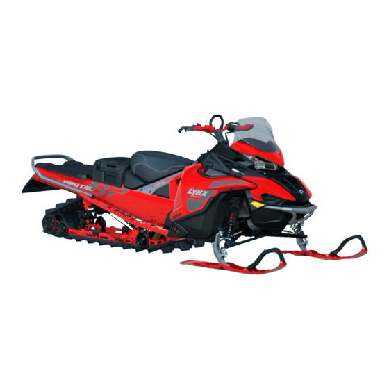
RADIEN UTILITY E-TEC AND
EFI SERIES
OPERATOR’S
GUIDE
Includes Safety, Use and Maintenance
Information
Read this guide thoroughly. It contains important safety information.
Minimum recommended operator age: 16 years old. Keep this opera-
tor’s guide in the vehicle.
619901003
WARNING
Original
Instructions
Related Manuals for BRP Lynx E-TEC Series
Summary of Contents for BRP Lynx E-TEC Series
-
Page 1
RADIEN UTILITY E-TEC AND EFI SERIES OPERATOR’S GUIDE Includes Safety, Use and Maintenance Information WARNING Read this guide thoroughly. It contains important safety information. Minimum recommended operator age: 16 years old. Keep this opera- tor’s guide in the vehicle. 619901003 Original Instructions… -
Page 2
. . p p 6 6 5 5 w w a a r r n n i i n n g g s s . . c c a a . . g g o o v v / / p p r r o o d d u u c c t t s s / / p p a a s s s s e e n n g g e e r r — — v v e e h h i i c c l l e e . . All rights reserved. No parts of this guide may be reproduced in any form without the prior written permission of Bombardier Recreational Products Inc. ©Bombardier Recreational Products Inc. (BRP) 2021 BRP Inc. -
Page 3
Liechtenstein), the Commonwealth of the Independent States (including Ukraine and Turkmenistan) and Turkey, products are distributed and serviced by BRP European Distribution S. A. and other affiliates or subsidiaries of BRP. For all other countries, products are distributed and serviced by Bom- bardier Recreational Products Inc. -
Page 4
OPERATOR’S GUIDE Models 49 Ranger 600R E-TEC 59 Ranger 600 EFI Commander 600R E-TEC XTerrain Brutal 850 E-TEC… -
Page 5
T T A A B B L L E E O O F F C C O O N N T T E E N N T T S S G G E E N N E E R R A A L L I I N N F F O O R R M M A A T T I I O O N N . -
Page 6
TABLE OF CONTENTS I I N N J J E E C C T T I I O O N N O O I I L L ……………………4 4 6 6 V V E E H H I I C C L L E E T T R R A A N N S S P P O O R R T T A A T T I I O O N N . -
Page 7
Pairing a Helmet ………… 182 BRP Connect App ……….182 Quick Tour of the BRP Connect App ……183 Messages in Multifunction Gauge……… 186 F F U U E E L L ……………………….1 1 8 8 8 8 Fuel Requirements ………. -
Page 8
TABLE OF CONTENTS Drive Belt …………238 Drive Pulley…………244 Track …………..248 Suspension …………257 Skis…………..260 Fuses…………..260 Headlights …………263 Battery …………… 267 V V E E H H I I C C L L E E C C A A R R E E ………………….. . 2 2 7 7 4 4 Post-Operation Care ………. -
Page 9
WARRANTY COVERAGE PERIOD ……319 CONDITIONS TO HAVE WARRANTY COVERAGE … 320 WHAT TO DO TO OBTAIN WARRANTY COVERAGE ..321 WHAT BRP WILL DO ……….321 TRANSFER …………321 CONSUMER ASSISTANCE……..322 B B R R P P F F I I N N L L A A N N D D O O Y Y L L I I M M I I T T E E D D W W A A R R R R A A N N T T Y Y F F O O R R T T H H E E E E U U R R O O P P E E A A N N… -
Page 10
TABLE OF CONTENTS Europe …………… 347 North America …………347 Oceania ………….. 347 South America …………347 C C H H A A N N G G E E O O F F A A D D D D R R E E S S S S / / O O W W N N E E R R S S H H I I P P …………3 3 4 4 8 8… -
Page 11
G G E E N N E E R R A A L L I I N N F F O O R R M M A A T T I I O O N N… -
Page 12
Congratulations on your purchase of a new BRP snowmobile. What- ever model you have chosen, it is backed by the Bombardier Recrea- tional Products Inc. (BRP) warranty and a network of authorized BRP snowmobile dealers ready to provide the parts, service or accessories you may require. -
Page 13
K K N N O O W W B B E E F F O O R R E E Y Y O O U U G G O O To learn how to reduce the risk for you, your passenger or bystanders being injured or killed, read the following sections before you operate the vehicle: –… -
Page 14
S S A A F F E E T T Y Y M M E E S S S S A A G G E E S S This operator’s guide utilizes the following symbols and words to em- phasize particular information: The safety alert symbol indicates a potential injury hazard. -
Page 15
Due to late changes, some differences between the manufactured product and the descrip- tions and/or specifications in this guide may occur. BRP reserves the right at any time to discontinue or change specifications, designs, fea- tures, models or equipment without incurring any obligation upon itself. -
Page 16
Help us lead it down the right path! From all of us at BRP, thank you for doing your share. -
Page 17
Finally, Light Treading is the sign of a smart snowmobiler. You don’t have to leave big tracks or careen through a virgin forest to show you can ride. So whether you’re driving a high performance BRP snowmo- bile or any other make or model, show you know what you’re doing. -
Page 18
RESPECT OF THE ENVIRONMENT This page is intention- ally blank… -
Page 19
S S A A F F E E T T Y Y I I N N F F O O R R M M A A T T I I O O N N SAFETY INFORMATION… -
Page 20
Be sure to contact the local authorities for infor- mation regarding the legal operation of a snowmobile in the intended jurisdiction of use. BRP highly recommends that you take a safety rid- ing course. Basic training is required for the safe operation of any snowmobile. -
Page 21
BEFORE YOU GO P P r r o o t t e e c c t t i i v v e e G G e e a a r r Proper snowmobile clothing should be worn by all riders. It should be comfortable and not too tight. -
Page 22
BEFORE YOU GO Avalanche beacon* *When riding in an area with avalanche risk SAFETY INFORMATION… -
Page 23
G G E E T T F F A A M M I I L L I I A A R R W W I I T T H H T T H H E E S S N N O O W W M M O O B B I I L L E E This vehicle may exceed the performance of other vehicles you may have ridden. -
Page 24
GET FAMILIAR WITH THE SNOWMOBILE the front and rear of the snowmobile are out of balance due to an in- correct combination of traction enhancing products, the snowmobile may tend to oversteer or understeer, which could lead to a loss of control. -
Page 25
– Always adjust the suspensions according to the cargo load. Refer to Tune Your Ride subsection for more details. – Never carry a load unless it is properly secured using a BRP LinQ certified accessory. Compatible accessories which are not BRP certified may not be considered as fit for this purpose. -
Page 26
Such features include various guards and consoles, plus reflective materials and safety labels. Do not make unauthorized modifications, or use attachments or ac- cessories that are not approved by BRP. Since these changes have SAFETY INFORMATION… -
Page 27
GET FAMILIAR WITH THE SNOWMOBILE not been tested by BRP, they may increase the risk of crashes or inju- ries, and they can make the vehicle illegal. Also, accessories are designed for specific applicable models only. It is not recommended for units other than the one (those) for which it was sold. -
Page 28
Installing track studs and tunnel protector(s) requires technical knowl- edge. To ensure safe and proper installation, BRP recommends to have the studs installed by your dealer. For maintenance and replacement refer to Track in Maintenance Procedures . -
Page 29
GET FAMILIAR WITH THE SNOWMOBILE O O V V E E R R S S T T E E E E R R I I N N G G U U n n d d e e r r s s t t e e e e r r i i n n g g In certain conditions, the use of studs on the track could make the snowmobile prone to understeering if the skis are not equipped with more aggressive ski carbide runners, see illustration. -
Page 30
GET FAMILIAR WITH THE SNOWMOBILE C C o o n n t t r r o o l l l l e e d d D D r r i i v v i i n n g g A balanced combination of carbide ski runners and studs on the track ensures adequate control and better handling, see illustration. -
Page 31
R R I I D D E E S S A A F F E E L L Y Y R R i i d d e e r r P P o o s s i i t t i i o o n n ( ( F F o o r r w w a a r r d d O O p p e e r r a a t t i i o o n n ) ) Your riding position and balance are the two basic principles of making your snowmobile go where you want it to. -
Page 32
RIDE SAFELY K K n n e e e e l l i i n n g g This position is achieved by placing one foot firmly on the running board and the opposite knee on the seat. Avoid abrupt stops. SAFETY INFORMATION… -
Page 33
RIDE SAFELY S S t t a a n n d d i i n n g g Place both feet on the running boards. Knees should be flexed to ab- sorb the shock from surface bumps. This is an effective position to see better and to shift weight as conditions dictate. -
Page 34
RIDE SAFELY – Ensure the path behind is clear of obstacles or bystanders before proceeding in reverse. – BRP recommends sitting on your snowmobile when operating in reverse. – Avoid standing up. Your weight could shift forward against throttle lever while operating in reverse, causing an unexpected accelera- tion. -
Page 35
RIDE SAFELY Braking ability and steering control are reduced when riding with a passenger. Decrease speed and allow extra space to maneuver. R R i i d d i i n n g g A A l l o o n n e e Venturing out alone with your snowmobile could also be hazardous. -
Page 36
RIDE SAFELY warning or caution. F F O O L L L L O O W W I I N N G G O O N N C C O O M M I I N N G G S S N N O O W W M M O O S S N N O O W W M M O O B B I I L L E E S S B B I I L L E E S S… -
Page 37
RIDE SAFELY terrain condition, stopping may require a little more space than you think. Play it safe. Be prepared to use evasive driving. On land or water, fog or visibility-limiting snow can form. If you must proceed into the fog or heavy snow, do so slowly with your lights on and watch intently for hazards. -
Page 38
RIDE SAFELY – Always use a wide-base snowmobile stand with a rear deflector panel if it is necessary to rotate track – When the track is raised off the ground, only run it at the lowest possible speed. Centrifugal force could cause debris, damaged or loose studs, pieces of torn track, or an entire severed track to be violently thrown backwards out of the tunnel with tremendous force –… -
Page 39
RIDE SAFELY F F r r o o z z e e n n W W a a t t e e r r Traveling frozen lakes and rivers can be fatal. Avoid waterways. If you are in an unfamiliar area, ask the local authorities or residents about the ice condition, inlets, outlets, springs, fast moving currents or other hazards. -
Page 40
RIDE SAFELY speed is reached, slow down by braking but apply the brake with fre- quent light pressure. Never jam the brake and lock the track. S S i i d d e e H H i i l l l l When crossing a side hill or traversing up or downhill, certain proce- dures must be followed. -
Page 41
RIDE SAFELY allow you to stop in time when you see an unknown or dangerous ob- ject ahead. Stay on established trails and never operate in unfamiliar territory. Be sure both headlights and taillight are working and clean. U U n n f f a a m m i i l l i i a a r r T T e e r r r r i i t t o o r r y y Whenever you enter an area that is new to you, drive with extreme caution. -
Page 42
RIDE SAFELY come to a complete stop back from the road’s edge. In some cases, you will be approaching the road from a ditch or snowbank. Choose a place where you know you can climb without difficulty. Stop com- pletely at the top of the bank and wait for all traffic to clear. Then, look carefully in both directions before crossing at a 90°… -
Page 43
– Never start or operate the engine if the fuel cap is not properly installed. – Use only a BRP approved LinQ fuel caddy to carry extra fuel on the vehicle. It should be properly installed and secured. Gasoline is poisonous and can cause injury or death. -
Page 44
P P R R A A C C T T I I C C E E E E X X E E R R C C I I S S E E S S Practice alone the following exercises after having done the entire Pre-ride inspection. -
Page 45
PRACTICE EXERCISES – Start the engine and release the parking brake lever. – Slowly apply throttle until the vehicle starts to creep forward. As soon as you start moving release the throttle and coast, then press the brake lever to stop. –… -
Page 46
PRACTICE EXERCISES – Start at one end of the straightaway and accelerate to 8 km/h (5MPH). Partway down the straightaway, release the throttle com- pletely and brake quickly. – Keep head and eyes up, keep handlebar straight, and do not re- lease the brake until fully stopped. -
Page 47
F F U U E E L L I I N N G G Fuel is flammable and explosive under certain conditions. – Never use an open flame to check fuel level. – Never smoke or allow flame or spark in vicinity. –… -
Page 48
I I N N J J E E C C T T I I O O N N O O I I L L Injection Oil is flammable when heated. – Never use an open flame to check oil level. –… -
Page 49
V V E E H H I I C C L L E E T T R R A A N N S S P P O O R R T T A A T T I I O O N N Make sure that oil reservoir and fuel tank caps are properly installed. -
Page 50
The following labels are on your vehicle and they should be consid- ered permanent parts of the vehicle. If missing or damaged, the decals can be replaced free of charge. Visit an authorized BRP snowmobile dealer. N N O O T T E E : :… -
Page 51
SAFETY INFORMATION ON THE VEHICLE R R o o t t a a t t i i n n g g P P a a r r t t s s — — W W a a r r n n i i n n g g L L a a b b e e l l W W A A R R N N I I N N G G B B e e w w a a r r e e o o f f r r o o t t a a t t i i n n g g p p a a r r t t s s 516009920… -
Page 52
SAFETY INFORMATION ON THE VEHICLE SAFETY INFORMATION… -
Page 53
SAFETY INFORMATION ON THE VEHICLE S S h h o o c c k k A A b b s s o o r r b b e e r r — — W W a a r r n n i i n n g g L L a a b b e e l l S S H H O O C C K K A A B B S S O O R R B B E E R R S S — — W W A A R R N N I I N N G G L L A A B B E E L L SAFETY INFORMATION… -
Page 54
SAFETY INFORMATION ON THE VEHICLE D D i i s s c c o o n n n n e e c c t t f f u u e e l l i i n n j j e e c c t t o o r r s s — — W W a a r r n n i i n n g g L L a a b b e e l l Always electrically disconnect both fuel injectors prior to… -
Page 55
SAFETY INFORMATION ON THE VEHICLE SAFETY INFORMATION… -
Page 56
SAFETY INFORMATION ON THE VEHICLE P P u u l l l l e e y y G G u u a a r r d d a a n n d d D D r r i i v v e e P P u u l l l l e e y y T T i i g g h h t t e e n n i i n n g g T T o o r r q q u u e e — — W W a a r r n n i i n n g g a a n n d d N N o o t t i i c c e e L L a a b b e e l l W W A A R R N N I I N N G G T T h h i i s s g g u u a a r r d d m m u u s s t t A A L L W W A A Y Y S S b b e e i i n n p p l l a a c c e e w w h h e e n n e e n n g g i i n n e e i i s s r r u u n n n n i i n n g g . -
Page 57
SAFETY INFORMATION ON THE VEHICLE H H o o t t p p a a r r t t s s — — C C a a u u t t i i o o n n L L a a b b e e l l C C A A U U T T I I O O N N B B e e w w a a r r e e o o f f h h o o t t p p a a r r t t s s . -
Page 58
SAFETY INFORMATION ON THE VEHICLE D D o o N N o o t t O O p p e e n n W W h h e e n n H H o o t t — — W W a a r r n n i i n n g g L L a a b b e e l l D D O O N N O O T T O O P P E E N N W W H H E E N N H H O O T T — — W W A A R R N N I I N N G G L L A A B B E E L L SAFETY INFORMATION… -
Page 59
SAFETY INFORMATION ON THE VEHICLE H H o o t t P P a a r r t t s s — — C C a a u u t t i i o o n n L L a a b b e e l l C C A A U U T T I I O O N N B B e e w w a a r r e e o o f f H H O O T T p p a a r r t t s s . -
Page 60
SAFETY INFORMATION ON THE VEHICLE SAFETY INFORMATION… -
Page 61
SAFETY INFORMATION ON THE VEHICLE D D i i s s k k G G u u a a r r d d — — W W a a r r n n i i n n g g L L a a b b e e l l W W A A R R N N I I N N G G T T h h i i s s g g u u a a r r d d m m u u s s t t A A L L W W A A Y Y S S b b e e i i n n p p l l a a c c e e w w h h e e n n e e n n g g i i n n e e i i s s r r u u n n n n i i n n g g . -
Page 62
SAFETY INFORMATION ON THE VEHICLE C C o o r r r r e e c c t t T T o o w w i i n n g g D D i i r r e e c c t t i i o o n n — — W W a a r r n n i i n n g g L L a a b b e e l l W W A A R R N N I I N N G G –… -
Page 63
SAFETY INFORMATION ON THE VEHICLE S S a a f f e e t t y y — — W W a a r r n n i i n n g g L L a a b b e e l l ( ( 4 4 9 9 R R a a n n g g e e r r ) ) S S A A F F E E T T Y Y — — W W A A R R N N I I N N G G L L A A B B E E L L SAFETY INFORMATION… -
Page 64
SAFETY INFORMATION ON THE VEHICLE SAFETY INFORMATION… -
Page 65
SAFETY INFORMATION ON THE VEHICLE D D r r i i v v i i n n g g a a n n d d S S t t a a r r t t i i n n g g P P r r o o c c e e d d u u r r e e s s — — W W a a r r n n i i n n g g L L a a b b e e l l ( ( 4 4 9 9 R R a a n n g g e e r r ) ) D D R R I I V V I I N N G G A A N N D D S S T T A A R R T T I I N N G G P P R R O O C C E E D D U U R R E E S S — — W W A A R R N N I I N N G G L L A A B B E E L L SAFETY INFORMATION… -
Page 66
SAFETY INFORMATION ON THE VEHICLE SAFETY INFORMATION… -
Page 67
SAFETY INFORMATION ON THE VEHICLE P P a a s s s s e e n n g g e e r r — — W W a a r r n n i i n n g g L L a a b b e e l l ( ( 4 4 9 9 R R a a n n g g e e r r ) ) P P A A S S S S E E N N G G E E R R — — W W A A R R N N I I N N G G L L A A B B E E L L SAFETY INFORMATION… -
Page 68
SAFETY INFORMATION ON THE VEHICLE SAFETY INFORMATION… -
Page 69
SAFETY INFORMATION ON THE VEHICLE P P a a s s s s e e n n g g e e r r H H a a n n d d l l e e s s — — W W a a r r n n i i n n g g L L a a b b e e l l W W A A R R N N I I N N G G –… -
Page 70
SAFETY INFORMATION ON THE VEHICLE 516009977 P P A A S S S S E E N N G G E E R R H H A A N N D D L L E E S S — — W W A A R R N N I I N N G G L L A A B B E E L L SAFETY INFORMATION… -
Page 71
SAFETY INFORMATION ON THE VEHICLE SAFETY INFORMATION… -
Page 72
SAFETY INFORMATION ON THE VEHICLE M M a a x x i i m m u u m m S S p p e e c c i i f f i i c c a a t t i i o o n n s s — — W W a a r r n n i i n n g g L L a a b b e e l l ( ( 4 4 9 9 R R a a n n g g e e r r ) ) W W A A R R N N I I N N G G –… -
Page 73
SAFETY INFORMATION ON THE VEHICLE P P r r o o h h i i b b i i t t i i o o n n s s — — W W a a r r n n i i n n g g L L a a b b e e l l ( ( 4 4 9 9 R R a a n n g g e e r r ) ) W W A A R R N N I I N N G G — — N N E E V V E E R R s s t t a a n n d d b b e e h h i i n n d d o o r r n n e e a a r r a a r r o o t t a a t t i i n n g g t t r r a a c c k k . -
Page 74
SAFETY INFORMATION ON THE VEHICLE S S t t a a r r t t i i n n g g P P r r o o c c e e d d u u r r e e ( ( F F i i n n n n i i s s h h ) ) — — W W a a r r n n i i n n g g L L a a b b e e l l ( ( E E x x c c e e p p t t 4 4 9 9 R R a a n n g g e e r r ) ) S S T T A A R R T T I I N N G G P P R R O O C C E E D D U U R R E E ( ( F F I I N N N N I I S S H H ) ) —… -
Page 75
SAFETY INFORMATION ON THE VEHICLE SAFETY INFORMATION… -
Page 76
SAFETY INFORMATION ON THE VEHICLE S S t t a a r r t t i i n n g g P P r r o o c c e e d d u u r r e e ( ( S S w w e e d d i i s s h h ) ) — — W W a a r r n n i i n n g g L L a a b b e e l l ( ( E E x x c c e e p p t t 4 4 9 9 R R a a n n g g e e r r ) ) D D R R I I V V I I N N G G A A N N D D S S T T A A R R T T I I N N G G P P R R O O C C E E D D U U R R E E S S — — W W A A R R N N I I N N G G L L A A B B E E L L SAFETY INFORMATION… -
Page 77
SAFETY INFORMATION ON THE VEHICLE SAFETY INFORMATION… -
Page 78
SAFETY INFORMATION ON THE VEHICLE S S t t a a r r t t i i n n g g P P r r o o c c e e d d u u r r e e ( ( E E n n g g l l i i s s h h ) ) — — W W a a r r n n i i n n g g L L a a b b e e l l ( ( E E x x c c e e p p t t 4 4 9 9 R R a a n n g g e e r r ) ) S S T T A A R R T T I I N N G G P P R R O O C C E E D D U U R R E E ( ( E E N N G G L L I I S S H H ) ) —… -
Page 79
SAFETY INFORMATION ON THE VEHICLE T T r r a a c c k k S S t t u u d d d d i i n n g g — — W W a a r r n n i i n n g g L L a a b b e e l l W W A A R R N N I I N N G G –… -
Page 80
SAFETY INFORMATION ON THE VEHICLE P P a a s s s s e e n n g g e e r r S S e e a a t t — — W W a a r r n n i i n n g g L L a a b b e e l l W W A A R R N N I I N N G G B B E E F F O O R R E E r r i i d d i i n n g g , , A A L L W W A A Y Y S S m m a a k k e e s s u u r r e e t t h h a a t t t t h h e e l l a a t t c c h h o o n n e e a a c c h h s s i i d d e e o o f f t t h h e e s s e e a a t t o o r r t t h h e e a a c c c c e e s s s s o o r r y y i i s s f f u u l l l l y y e e n n g g a a g g e e d d . -
Page 81
SAFETY INFORMATION ON THE VEHICLE R R e e a a r r S S t t o o r r a a g g e e C C o o m m p p a a r r t t m m e e n n t t — — W W a a r r n n i i n n g g L L a a b b e e l l W W A A R R N N I I N N G G T T o o r r e e d d u u c c e e t t h h e e r r i i s s k k o o f f s s e e v v e e r r e e i i n n j j u u r r y y o o r r d d e e a a t t h h : : –… -
Page 82
SAFETY INFORMATION ON THE VEHICLE M M a a x x i i m m u u m m S S p p e e c c i i f f i i c c a a t t i i o o n n s s — — W W a a r r n n i i n n g g L L a a b b e e l l W W A A R R N N I I N N G G –… -
Page 83
SAFETY INFORMATION ON THE VEHICLE SAFETY INFORMATION… -
Page 84
SAFETY INFORMATION ON THE VEHICLE P P r r o o h h i i b b i i t t i i o o n n s s — — W W a a r r n n i i n n g g L L a a b b e e l l W W A A R R N N I I N N G G — — N N E E V V E E R R s s t t a a n n d d b b e e h h i i n n d d o o r r n n e e a a r r a a r r o o t t a a t t i i n n g g t t r r a a c c k k . -
Page 85
SAFETY INFORMATION ON THE VEHICLE SAFETY INFORMATION… -
Page 86
SAFETY INFORMATION ON THE VEHICLE T T e e c c h h n n i i c c a a l l I I n n f f o o r r m m a a t t i i o o n n L L a a b b e e l l s s A A d d j j u u s s t t m m e e n n t t T T o o o o l l s s –… -
Page 87
SAFETY INFORMATION ON THE VEHICLE R R e e c c o o m m m m e e n n d d e e d d F F u u e e l l — — N N o o t t i i c c e e L L a a b b e e l l Refer to the Technical Specifications for appropriate fuel type for your vehicle engine. -
Page 88
SAFETY INFORMATION ON THE VEHICLE SAFETY INFORMATION… -
Page 89
BRP XPS approved lubricant. BRP recommends the use of its XPS approved lubricant or equivalent. Damages caused by oil which is not suitable for this engine may not be covered by the BRP limited warranty. See the operator’ s guide. 516008439 OIL LEVEL… -
Page 90
SAFETY INFORMATION ON THE VEHICLE SAFETY INFORMATION… -
Page 91
SAFETY INFORMATION ON THE VEHICLE T T r r a a c c k k D D e e f f l l e e c c t t i i o o n n S S p p e e c c i i f f i i c c a a t t i i o o n n s s Refer to the Technical Specifications in this operator’s guide or to label on the vehicle, for appropriate track tension for your vehicle. -
Page 92
5. Check fuel and injection oil for levels and leaks. Replenish if neces- sary and in case of any leaks; you should seek service from an au- thorized BRP snowmobile dealer, repair shop, or person of your own choosing for maintenance, repair, or replacement. -
Page 93
PRE-RIDE INSPECTION P P r r e e — — R R i i d d e e C C h h e e c c k k L L i i s s t t ✔ ITEM OPERATION BODY INCLUDING SEAT, FOOTRESTS, Check condition and remove snow or LIGHTS, AIR FILTER,… -
Page 94
PRE-RIDE INSPECTION Check for proper operation. LIGHTS HORN BUTTON (IF Check for proper operation. EQUIPPED) SAFETY INFORMATION… -
Page 95
V V E E H H I I C C L L E E I I N N F F O O R R M M A A T T I I O O N N… -
Page 96
P P R R I I M M A A R R Y Y C C O O N N T T R R O O L L S S H H a a n n d d l l e e b b a a r r The handlebar controls the steering of the snowmobile. -
Page 97
PRIMARY CONTROLS Designed to be thumb activated. When squeezed, it increases the en- gine speed. When released, engine speed returns automatically to idle. C C A A B B L L E E T T H H R R O O T T T T L L E E L L E E V V E E R R 1. -
Page 98
PRIMARY CONTROLS T T Y Y P P I I C C A A L L 1. Brake lever 2. To apply brake P P a a r r k k i i n n g g B B r r a a k k e e L L e e v v e e r r Parking brake lever is located on the LH side of handlebar. -
Page 99
PRIMARY CONTROLS W W A A R R N N I I N N G G M M a a k k e e s s u u r r e e p p a a r r k k i i n n g g b b r r a a k k e e i i s s f f u u l l l l y y d d i i s s e e n n g g a a g g e e d d b b e e f f o o r r e e o o p p e e r r a a t t i i n n g g t t h h e e s s n n o o w w m m o o b b i i l l e e . -
Page 100
PRIMARY CONTROLS T T Y Y P P I I C C A A L L To stop the engine in an emergency, push the switch down in OFF po- sition and simultaneously apply the brake. O O F F F F P P O O S S I I T T I I O O N N To allow engine starting, pull the switch up in ON position. -
Page 101
PRIMARY CONTROLS O O N N P P O O S S I I T T I I O O N N All operators of the snowmobile should familiarize themselves with the function of the emergency engine stop switch by using it several times on first outing and whenever stopping the engine thereafter. -
Page 102
S S E E C C O O N N D D A A R R Y Y C C O O N N T T R R O O L L S S Some features may not apply to your model or could be optional. Vehicle safety labels are not shown on illustrations. -
Page 103
SECONDARY CONTROLS T T Y Y P P I I C C A A L L 1. Start/Electronic Reverse button 2. Headlights dimmer switch 3. Heated grips switch 4. Heated throttle lever switch 5. Menu/set button S S t t a a r r t t / / E E l l e e c c t t r r o o n n i i c c R R e e v v e e r r s s e e B B u u t t t t o o n n 1. -
Page 104
SECONDARY CONTROLS Press to start engine. Refer to Engine Starting Procedure in basic procedures . Once engine is started, press to engage the electronic reverse. Refer to Shifting in Reverse in basic procedures for procedure. H H e e a a d d l l i i g g h h t t s s D D i i m m m m e e r r S S w w i i t t c c h h Press to select HI or LOW beam. -
Page 105
SECONDARY CONTROLS M M O O D D E E L L S S W W I I T T H H O O U U T T T T H H E E L L A A R R G G E E P P A A N N O O R R A A M M I I C C 7 7 . . 8 8 » » W W I I D D E E L L C C D D D D I I S S P P L L A A Y Y S S H H O O W W N N 1. -
Page 106
SECONDARY CONTROLS Depress switch as required to select heating intensity to keep your thumb at a comfortable temperature. V V A A R R I I A A B B L L E E I I N N T T E E N N S S I I T T Y Y 1. -
Page 107
SECONDARY CONTROLS M M O O D D E E L L S S W W I I T T H H O O U U T T T T H H E E L L A A R R G G E E P P A A N N O O R R A A M M I I C C 7 7 . . 8 8 » » W W I I D D E E L L C C D D D D I I S S P P L L A A Y Y S S H H O O W W N N 1. -
Page 108
SECONDARY CONTROLS M M E E N N U U / / S S E E T T B B U U T T T T O O N N 1. Menu function 2. SET function Refer to Gauge for complete information. A A u u d d i i o o V V o o l l u u m m e e C C o o n n t t r r o o l l M M o o d d e e l l s s w w i i t t h h t t h h e e L L a a r r g g e e P P a a n n o o r r a a m m i i c c 7 7 . -
Page 109
SECONDARY CONTROLS 1. Volume DOWN/Cancelling a call 2. Volume UP/Answering a call Refer to Large Panoramic 7.8” Wide LCD Display section for complete information. R R o o t t a a r r y y C C o o n n t t r r o o l l The rotary control is located on the left side of the console. -
Page 110
– Specific vehicle data button allow to see engine temperature, and battery voltage. It will also shown air suspension adjustment (if equipped) – BRP Connect button: quick access to already downloaded APPS. 1. Audio control 2. Center knob 3. Vehicle data button 4. -
Page 111
SECONDARY CONTROLS C C o o n n s s o o l l e e S S w w i i t t c c h h ( ( i i f f e e q q u u i i p p p p e e d d ) ) 1. -
Page 112
The balance between the temperature of the throttle lever and the grips can be adjusted. Contact an author- ized BRP snowmobile dealer. Depress switch as required to select heating intensity to keep your hands at a comfortable temperature. -
Page 113
SECONDARY CONTROLS H H E E A A T T E E D D G G R R I I P P S S D D I I S S P P L L A A Y Y Heated grips will be in OFF position when there are no bars displayed on the gauge. -
Page 114
SECONDARY CONTROLS Use this lever to select gears. The gearbox has two forward gears and a neutral. Shifting from one position to another is possible at speeds lower than 30 km/h (19 MPH) C C A A U U T T I I O O N N S S h h i i f f t t i i n n g g a a t t a a s s p p e e e e d d f f a a s s t t e e r r t t h h a a n n 3 3 0 0 k k m m / / h h ( ( 1 1 9 9 M M P P H H ) ) m m a a y y c c a a u u s s e e s s e e r r i i o o u u s s d d a a m m a a g g e e t t o o t t h h e e g g e e a a r r b b o o x x . -
Page 115
SECONDARY CONTROLS R R e e w w i i n n d d S S t t a a r r t t e e r r H H a a n n d d l l e e Auto-rewind type located on right hand side of snowmobile. -
Page 116
SECONDARY CONTROLS H H o o r r n n B B u u t t t t o o n n ( ( i i f f e e q q u u i i p p p p e e d d ) ) F F o o r r v v e e h h i i c c l l e e s s s s o o l l d d i i n n F F i i n n l l a a n n d d Press on the horn button to activate the horn. -
Page 117
B B O O D D Y Y A A N N D D S S E E A A T T W W i i n n d d s s h h i i e e l l d d R R e e m m o o v v i i n n g g t t h h e e W W i i n n d d s s h h i i e e l l d d 1. -
Page 118
BODY AND SEAT C C E E N N T T E E R R T T A A B B — — W W I I T T H H S S I I D D E E D D E E F F L L E E C C T T O O R R S S I I n n s s t t a a l l l l i i n n g g t t h h e e W W i i n n d d s s h h i i e e l l d d 1. -
Page 119
BODY AND SEAT C C E E N N T T E E R R T T A A B B — — W W I I T T H H S S I I D D E E D D E E F F L L E E C C T T O O R R S S 3. -
Page 120
BODY AND SEAT W W I I T T H H S S I I D D E E D D E E F F L L E E C C T T O O R R S S F F r r o o n n t t S S t t o o r r a a g g e e C C o o m m p p a a r r t t m m e e n n t t A storage compartment is located at the front of the vehicle, above the gauge. -
Page 121
BODY AND SEAT T T Y Y P P I I C C A A L L N N O O T T E E : : When closing, make sure cover is secured properly. You will hear a «clic». H H o o o o d d R R e e m m o o v v i i n n g g t t h h e e H H o o o o d d 1. -
Page 122
BODY AND SEAT 2. Pull the hood forward. I I n n s s t t a a l l l l i i n n g g t t h h e e H H o o o o d d 1. -
Page 123
BODY AND SEAT 3. Remove the gauge support retaining screws. T T Y Y P P I I C C A A L L 4. Lift the front of the gauge support, then slide it forward to remove it. -
Page 124
BODY AND SEAT 5. Disconnect gauge connector and remove support . 6. Lift storage compartement and disconnect 12V power outlet con- nectors before removing the storage compartment (if equipped). 7. Disconnect the headlight and MAPTS (2– stroke engine) connectors. -
Page 125
BODY AND SEAT T T Y Y P P I I C C A A L L 8. Loosen the air intake duct clamp. 9. Remove the upper body module retaining screws on both sides. -
Page 126
BODY AND SEAT 10. Remove the upper body module. 1. Grab the upper body module in the gauge support section. 2. Pull the module forward. 3. Remove the module from the vehicle. I I n n s s t t a a l l l l i i n n g g t t h h e e U U p p p p e e r r B B o o d d y y M M o o d d u u l l e e The installation is the reverse of the removal procedure. -
Page 127
BODY AND SEAT 7. Install gauge, secure with the screws. t t i i g g h h t t e e n n i i n n g g T T o o r r q q u u e e Gauge screws 2.5 ±… -
Page 128
BODY AND SEAT 3. Disengage panel tabs. 4. Free panel from side hull tab. -
Page 129
BODY AND SEAT N N O O T T I I C C E E M M a a k k e e s s u u r r e e t t o o p p l l a a c c e e p p a a n n e e l l i i n n a a s s a a f f e e p p l l a a c c e e t t o o a a v v o o i i d d s s c c r r a a t t c c h h i i n n g g . . I I n n s s t t a a l l l l i i n n g g t t h h e e S S i i d d e e P P a a n n e e l l s s The installation is the reverse of the removal procedure. -
Page 130
BODY AND SEAT C C R R O O S S S S C C U U T T V V I I E E W W O O F F S S E E A A T T F F O O A A M M 1. -
Page 131
BODY AND SEAT B B a a c c k k r r e e s s t t R R e e m m o o v v i i n n g g t t h h e e B B a a c c k k r r e e s s t t 1. -
Page 132
BODY AND SEAT I I n n s s t t a a l l l l i i n n g g t t h h e e B B a a c c k k r r e e s s t t The installation is the reverse of the removal procedure. -
Page 133
BODY AND SEAT 3. Reinstall the screws. Tighten to specification. T T i i g g h h t t e e n n i i n n g g T T o o r r q q u u e e 24.5 ±… -
Page 134
BODY AND SEAT S S e e a a t t — — 5 5 0 0 0 0 a a n n d d 6 6 0 0 0 0 m m m m ( ( 2 2 0 0 a a n n d d 2 2 4 4 i i n n . . ) ) T T u u n n n n e e l l W W i i d d t t h h O O p p e e r r a a t t o o r r ’… -
Page 135
BODY AND SEAT P P a a s s s s e e n n g g e e r r S S e e a a t t ( ( i i f f e e q q u u i i p p p p e e d d ) ) W W A A R R N N I I N N G G A A n n y y p p a a s s s s e e n n g g e e r r m m u u s s t t b b e e a a b b l l e e t t o o f f i i r r m m l l y y l l a a y y i i s s f f e e e e t t o o n n t t h h e e f f o o o o t t r r e e s s t t s s a a n n d d k k e e e e p p h h i i s s h h a a n n d d s s o o n n t t h h e e h h a a n n d d h h o o l l d d s s a a t t a a l l l l t t i i m m e e s s w w h h e e n n s s e e a a t t e e d d . -
Page 136
BODY AND SEAT T T Y Y P P I I C C A A L L 2. Lift the seat to disconnect the electrical connector. 3. Remove passenger seat. I I n n s s t t a a l l l l i i n n g g t t h h e e P P a a s s s s e e n n g g e e r r S S e e a a t t The installation is the reverse of removal procedure. -
Page 137
BODY AND SEAT 1. First step 2. Second step W W A A R R N N I I N N G G E E n n s s u u r r e e t t h h e e l l a a t t c c h h i i s s o o n n t t h h e e s s e e c c o o n n d d s s t t e e p p b b e e f f o o r r e e r r i i d d i i n n g g . . -
Page 138
E E Q Q U U I I P P M M E E N N T T Some features may not apply to your model or could be optional. O O p p e e r r a a t t o o r r ‘ ‘ s s G G u u i i d d e e The Operator’s Guide should be stored in the Front Storage Compartment . -
Page 139
EQUIPMENT A A d d j j u u s s t t a a b b l l e e M M i i r r r r o o r r s s Each mirror can be adjusted to suit operator’s preference. W W A A R R N N I I N N G G A A d d j j u u s s t t w w i i t t h h v v e e h h i i c c l l e e a a t t r r e e s s t t i i n n a a s s a a f f e e p p l l a a c c e e . -
Page 140
EQUIPMENT 1. Mirrors M M o o u u n n t t a a i i n n S S t t r r a a p p This handlebar strap shall be used only to provide additional pulling force when snowmobile is stuck in a slanted position. -
Page 141
EQUIPMENT W W A A R R N N I I N N G G D D o o n n o o t t u u s s e e w w h h i i l l e e r r i i d d i i n n g g a a t t s s p p e e e e d d . . S S t t e e e e r r i i n n g g c c o o n n t t r r o o l l i i s s h h i i g g h h l l y y r r e e — — d d u u c c e e d d a a n n d d b b r r a a k k e e c c o o n n t t r r o o l l i i s s n n o o t t p p o o s s s s i i b b l l e e . -
Page 142
EQUIPMENT E E l l e e c c t t r r i i c c V V i i s s o o r r J J a a c c k k C C o o n n n n e e c c t t o o r r An electric visor can be connected to the jack connector. -
Page 143
EQUIPMENT T T Y Y P P I I C C A A L L Lift rear portion of guard then release from front tab. I I n n s s t t a a l l l l i i n n g g t t h h e e D D r r i i v v e e B B e e l l t t G G u u a a r r d d Insert belt guard tab in front support slot. -
Page 144
EQUIPMENT Position the rear portion of the belt guard over the retainer and secure it using the retaining pin. -
Page 145
EQUIPMENT S S p p a a r r e e D D r r i i v v e e B B e e l l t t H H o o l l d d e e r r A spare drive belt can be stored in a holder located on the drive belt guard. -
Page 146
EQUIPMENT T T Y Y P P I I C C A A L L 1. Drive belt guard 2. Slot Secure in place by sliding it behind the tabs. T T Y Y P P I I C C A A L L T T o o o o l l s s A part of the drive belt guard is designed to hold the tools allowing for basic maintenance. -
Page 147
EQUIPMENT The tools are supplied with the vehicle. They should always be in- stalled in their proper location and orientation. T T Y Y P P I I C C A A L L — — D D R R I I V V E E B B E E L L T T G G U U A A R R D D T T O O O O L L S S L L O O C C A A T T I I O O N N 1. -
Page 148
EQUIPMENT 2. Press the closed end on the retaining tabs. 3. Slide the Pulley expander and headlight adjustment tool short end into hole. P P U U L L L L E E Y Y E E X X P P A A N N D D E E R R A A N N D D H H E E A A D D L L I I G G H H T T A A D D J J U U S S T T M M E E N N T T T T O O O O L L 4. -
Page 149
EQUIPMENT R R e e a a r r S S t t o o r r a a g g e e C C o o m m p p a a r r t t m m e e n n t t A storage compartment is located at the rear of the seat, above the battery cover. -
Page 150
EQUIPMENT 1. Unlock seat latch 2. Tilt passenger seat Lift handle. -
Page 151
EQUIPMENT C C a a r r g g o o B B o o x x ( ( i i f f e e q q u u i i p p p p e e d d ) ) The cargo box is secured by LinQ attachment. -
Page 152
EQUIPMENT Turn LinQ levers as shown to lock. -
Page 153
EQUIPMENT H H i i t t c c h h ( ( i i f f e e q q u u i i p p p p e e d d ) ) N N O O T T E E : : Refer to decal on vehicle for towing weight capacities. -
Page 154
EQUIPMENT J J — — H H o o o o k k H H i i t t c c h h… -
Page 155
EQUIPMENT To open the hook, push and turn the handle to retract locking plate. -
Page 156
EQUIPMENT When attaching any accessory, always refer to the manufacturer’s recommendations. W W A A R R N N I I N N G G N N e e v v e e r r t t o o w w a a n n a a c c c c e e s s s s o o r r y y w w i i t t h h a a r r o o p p e e . . A A l l w w a a y y s s u u s s e e a a r r i i g g i i d d t t o o w w b b a a r r . . U U s s i i n n g g a a r r o o p p e e w w o o u u l l d d r r e e s s u u l l t t i i n n a a c c o o l l l l i i s s i i o o n n b b e e t t w w e e e e n n t t h h e e o o b b j j e e c c t t a a n n d d t t h h e e s s n n o o w w m m o o b b i i l l e e a a n n d d p p o o s s s s i i b b l l y y i i n n a a t t i i p p o o v v e e r r i i n n c c a a s s e e o o f f a a r r a a p p i i d d d d e e — — c c e e l l e e r r a a t t i i o o n n o o r r o o n n a a d d o o w w n n w w a a r r d d s s l l o o p p e e . -
Page 157
4 4 . . 5 5 ” ” D D I I G G I I T T A A L L D D I I S S P P L L A A Y Y M M u u l l t t i i f f u u n n c c t t i i o o n n D D i i s s p p l l a a y y L L o o w w e e r r D D i i s s p p l l a a y y May display the following: –… -
Page 158
4.5” DIGITAL DISPLAY L L e e f f t t L L a a t t e e r r a a l l D D i i s s p p l l a a y y The left lateral display includes: –… -
Page 159
4.5” DIGITAL DISPLAY T T r r i i p p D D i i s s p p l l a a y y This display shows trip informations: – Cumulative distance odometer – Trip A hours – Trip A distance (Km or mph) –… -
Page 160
4.5” DIGITAL DISPLAY L L i i g g h h t t s s D D e e s s c c r r i i p p t t i i o o n n RED — The engine temperature is too high. RED — Parking brake is engaged or malfunction of the brake system RED — The battery voltage too low or problem… -
Page 161
4.5” DIGITAL DISPLAY S S e e t t t t i i n n g g s s S S e e t t u u p p 1. Upper button (S) 2. Lower button (M) Using LOWER button, select S S E E T T T T I I N N G G S S and hold to enter setting menu. -
Page 162
S S e e t t t t i i n n g g L L a a n n g g u u a a g g e e The gauge display language can be changed. Refer to an authorized BRP snowmobile dealer for language availability and to setup the gauge to your preference. -
Page 163
7 7 . . 2 2 ” ” D D I I G G I I T T A A L L D D I I S S P P L L A A Y Y M M u u l l t t i i f f u u n n c c t t i i o o n n D D i i s s p p l l a a y y M M E E N N U U ( ( M M ) ) B B U U T T T T O O N N… -
Page 164
7.2” DIGITAL DISPLAY S S E E T T ( ( S S ) ) B B U U T T T T O O N N 1. Select the upper or center display by using the MENU (M) button on the multifunction switch. -
Page 165
7.2” DIGITAL DISPLAY S S E E T T ( ( S S ) ) B B U U T T T T O O N N Once the desired information is displayed, press the MENU (M) button or wait 5 seconds to confirm. M M E E N N U U ( ( M M ) ) B B U U T T T T O O N N To reset –… -
Page 166
7.2” DIGITAL DISPLAY L L o o w w e e r r D D i i s s p p l l a a y y May display the following: – Settings – Messages The SPEED display shows the Maximum and the averaged speed. Hold MENU button for 3 seconds to reset. -
Page 167
7.2” DIGITAL DISPLAY R R i i g g h h t t L L a a t t e e r r a a l l D D i i s s p p l l a a y y The right lateral display includes: –… -
Page 168
7.2” DIGITAL DISPLAY T T Y Y P P I I C C A A L L 1. MODE (M) button A A C C S S S S u u s s p p e e n n s s i i o o n n P P o o s s i i t t i i o o n n D D i i s s p p l l a a y y ( ( i i f f e e q q u u i i p p p p e e d d ) ) This display shows suspension setting. -
Page 169
7.2” DIGITAL DISPLAY Refer to tune your ride section for proper adjustment procedure. D D r r i i v v i i n n g g M M o o d d e e D D i i s s p p l l a a y y The driving mode display indicates the selected mode of operation: –… -
Page 170
7.2” DIGITAL DISPLAY N N O O T T E E : : When in STANDARD mode, no information is displayed. A message of the selected mode will be displayed on the lower display at activation and deactivation as follow: D D R R I I V V I I N N G G M M E E S S S S A A G G E E A A T T M M E E S S S S A A G G E E A A T T… -
Page 171
7.2” DIGITAL DISPLAY T T e e l l l l t t a a l l e e L L i i g g h h t t s s — — L L o o w w e e r r B B a a r r L L i i g g h h t t s s D D e e s s c c r r i i p p t t i i o o n n ORANGE — Vehicle malfunction… -
Page 172
S S e e t t t t i i n n g g L L a a n n g g u u a a g g e e The gauge display language can be changed. Refer to an authorized BRP snowmobile dealer for language availability and to setup the gauge to your preference. -
Page 173
L L A A R R G G E E P P A A N N O O R R A A M M I I C C 7 7 . . 8 8 ” ” W W I I D D E E L L C C D D D D I I S S P P L L A A Y Y B B a a s s i i c c F F u u n n c c t t i i o o n n s s L L C C D D D D i i s s p p l l a a y y… -
Page 174
LARGE PANORAMIC 7.8” WIDE LCD DISPLAY P P R R I I N N C C I I P P A A L L V V I I E E W W – Heated grips – Heated thumb S S E E C C O O N N D D A A R R Y Y V V I I E E W W — — H H E E A A T T E E D D E E L L E E M M E E N N T T S S… -
Page 175
The right lateral display includes: – Tachometer – Audio volume – Audio output indicator – Menu – BRP Connect – Phone – Statistics – Audio – Settings S S T T A A T T S S / / T T R R I I P P S S V V I I E E W W… -
Page 176
LARGE PANORAMIC 7.8” WIDE LCD DISPLAY S S E E T T T T I I N N G G S S V V I I E E W W N N a a v v i i g g a a t t i i n n g g i i n n t t h h e e D D i i g g i i t t a a l l D D i i s s p p l l a a y y W W A A R R N N I I N N G G R R e e a a d d i i n n g g o o r r t t a a m m p p e e r r i i n n g g w w i i t t h h t t h h e e m m u u l l t t i i f f u u n n c c t t i i o o n n g g a a u u g g e e c c a a n n d d i i s s t t r r a a c c t t y y o o u u f f r r o o m m t t h h e e o o p p e e r r a a t t i i o o n n o o f f t t h h e e v v e e h h i i c c l l e e , , p p a a r r t t i i c c u u l l a a r r l l y y f f r r o o m m c c o o n n — -… -
Page 177
LARGE PANORAMIC 7.8” WIDE LCD DISPLAY – BRP Connect – Phone – Statistics – Audio – Settings When an icon is selected, its related screen will appear. S S E E T T T T I I N N G G S S V V I I E E W W When an item is selected, this sets the item to the current value. -
Page 178
LARGE PANORAMIC 7.8” WIDE LCD DISPLAY T T e e l l l l t t a a l l e e L L i i g g h h t t s s — — L L o o w w e e r r B B a a r r L L i i g g h h t t s s D D e e s s c c r r i i p p t t i i o o n n ORANGE — Vehicle malfunction… -
Page 179
LARGE PANORAMIC 7.8” WIDE LCD DISPLAY I I c c o o n n s s a a n n d d I I n n d d i i c c a a t t o o r r s s — — M M u u l l t t i i f f u u n n c c t t i i o o n n D D i i s s p p l l a a y y D D e e s s c c r r i i p p t t i i o o n n I I c c o o n n Smartphone Network connection… -
Page 180
B B R R P P C C o o n n n n e e c c t t Before using BRP Connect, the app must be downloaded to the phone. The app can be downloaded from the Apple App Store or Goo- gle Play Store via a simple search. -
Page 181
LARGE PANORAMIC 7.8” WIDE LCD DISPLAY P P h h o o n n e e The phone menu is to access: – The phone history – The phone contact list N N O O T T E E : : To have access to the Phone menu, a phone and rider helmet must be paired. -
Page 182
LARGE PANORAMIC 7.8” WIDE LCD DISPLAY S S t t a a t t i i s s t t i i c c s s The Statistics menu is used to get : – Trip distance information – Trip elapsed time information –… -
Page 183
LARGE PANORAMIC 7.8” WIDE LCD DISPLAY S S e e t t t t i i n n g g s s The Settings menu is to: – Adjust clock – Pair Bluetooth devices – Phone – Rider headset – Passenger headset –… -
Page 184
1 1 ) ) D D o o w w n n l l o o a a d d t t h h e e B B R R P P C C o o n n n n e e c c t t S S m m a a r r t t p p h h o o n n e e A A p p p p Download the BRP Connect app via the App Store for Apple™ or the Google™… -
Page 185
LARGE PANORAMIC 7.8” WIDE LCD DISPLAY Push the joystick U U P P to select “Launch BRP Connect” and push the joystick R R I I G G H H T T . Select the app you would like to use and press the J J O O Y Y S S T T I I C C K K . -
Page 186
6. FAQ: This link takes you to answers of common questions asked by riders like you. An internet connection is required. 7. BRP Connect Tutorial: Need to know more? This link takes you to detailed instructions videos. An internet connection is required. -
Page 187
LARGE PANORAMIC 7.8” WIDE LCD DISPLAY 1. Currently Installed Apps 2. Available Apps… -
Page 188
BAD KEY authorized BRP snowmobile dealer. Use the right key for the vehicle or contact WRONG Wrong key an authorized BRP snowmobile dealer. – Stop and wait for engine to cool off. HIGH – Check for leaks. Engine is ENGINE –… -
Page 189
LARGE PANORAMIC 7.8” WIDE LCD DISPLAY * BRP recommends having the vehicle transport when in LIMP HOME. If you operate the vehicle in LIMP HOME, avoid abrupt maneuvers and immediately go to the nearest authorized BRP snowmobile dealer to have your vehicle serviced before riding again. -
Page 190
F F U U E E L L F F u u e e l l R R e e q q u u i i r r e e m m e e n n t t s s N N O O T T I I C C E E A A l l w w a a y y s s u u s s e e f f r r e e s s h h g g a a s s o o l l i i n n e e . -
Page 191
FUEL f f u u e e l l t t y y p p e e e e n n g g i i n n e e m m i i n n . . o o c c t t a a n n e e r r a a t t i i n n g g 87 Pump Posted AKI 600 EFI (RON+MON)/2) -
Page 192
FUEL W W A A R R N N I I N N G G F F u u e e l l i i s s f f l l a a m m m m a a b b l l e e a a n n d d e e x x p p l l o o s s i i v v e e u u n n d d e e r r c c e e r r t t a a i i n n c c o o n n d d i i t t i i o o n n s s . . N N e e v v e e r r u u s s e e a a n n o o p p e e n n f f l l a a m m e e t t o o c c h h e e c c k k f f u u e e l l l l e e v v e e l l . -
Page 193
FUEL 5. Pour fuel slowly so that air can escape from the tank and prevent fuel flow back. Be careful not to spill fuel. 6. Stop filling when the fuel reaches the bottom of filler neck. D D o o n n o o t t o o v v e e r r f f i i l l l l . -
Page 194
® engines were developed and validated using the XPS™ oil. BRP recommends the use of its XPS injection oil or an equivalent at all time. Damages caused by the use of an injection oil not suitable for this 2-stroke direct fuel injection engine may not be covered by the BRP Limited Warranty. -
Page 195
INJECTION OIL Marks on the tank indicates «3/8» and «1/2» of the total amount of oil. N N O O T T I I C C E E C C h h e e c c k k l l e e v v e e l l a a n n d d r r e e f f i i l l l l e e v v e e r r y y t t i i m m e e y y o o u u r r e e f f u u e e l l . . A A d d d d i i n n g g I I n n j j e e c c t t i i o o n n O O i i l l Remove injection oil reservoir cap. -
Page 196
B B R R E E A A K K — — I I N N P P E E R R I I O O D D O O p p e e r r a a t t i i o o n n D D u u r r i i n n g g B B r r e e a a k k — — I I n n E E n n g g i i n n e e During the break-in period: –… -
Page 197
B B A A S S I I C C P P R R O O C C E E D D U U R R E E S S E E n n g g i i n n e e S S t t a a r r t t i i n n g g P P r r o o c c e e d d u u r r e e P P r r o o c c e e d d u u r r e e 1. -
Page 198
BASIC PROCEDURES E E m m e e r r g g e e n n c c y y S S t t a a r r t t i i n n g g The engine can be started with the emergency starter rope supplied in the storage compartment, see Controls, Instruments and equipment . -
Page 199
BASIC PROCEDURES 1. Rope crossed 2. Rope to be winded 3. Rope end Wind rope two turns counterclockwise tightly around the drive pulley where shown. Pull the rope using a sharp, crisp pull so the rope comes free of the drive pulley. -
Page 200
BASIC PROCEDURES Start engine as per usual manual starting. W W A A R R N N I I N N G G W W h h e e n n s s t t a a r r t t i i n n g g t t h h e e s s n n o o w w m m o o b b i i l l e e i i n n a a n n e e m m e e r r g g e e n n c c y y s s i i t t u u a a t t i i o o n n , , u u s s i i n n g g d d r r i i v v e e p p u u l l l l e e y y , , d d o o n n o o t t r r e e i i n n s s t t a a l l l l t t h h e e b b e e l l t t g g u u a a r r d d a a n n d d r r e e t t u u r r n n s s l l o o w w l l y y t t o o h h a a v v e e s s n n o o w w m m o o b b i i l l e e r r e e p p a a i i r r e e d d . -
Page 201
BASIC PROCEDURES N N O O T T I I C C E E I I f f v v e e h h i i c c l l e e d d o o e e s s n n o o t t m m o o v v e e w w h h e e n n t t h h r r o o t t t t l l e e i i s s a a p p p p l l i i e e d d , , s s t t o o p p e e n n g g i i n n e e , , r r e e m m o o v v e e t t e e t t h h e e r r c c o o r r d d c c a a p p f f r r o o m m t t h h e e e e n n g g i i n n e e c c u u t t — — o o f f f f s s w w i i t t c c h h , , t t h h e e n n d d o o t t h h e e f f o o l l l l o o w w i i n n g g . -
Page 202
BASIC PROCEDURES 6 6 0 0 0 0 E E F F I I E E n n g g i i n n e e 3. With engine at idle speed, turn the ignition key clockwise and release. E E — — T T E E C C E E n n g g i i n n e e 4. -
Page 203
BASIC PROCEDURES A A l l l l E E n n g g i i n n e e s s 5. Wait until reverse beeper sounds, then gently depress throttle lever. W W A A R R N N I I N N G G T T h h e e r r e e v v e e r r s s e e s s p p e e e e d d i i s s n n o o t t l l i i m m i i t t e e d d . -
Page 204
BRP snowmobile dealer. If your snowmobile is to be used at an altitude outside the specified range, have it calibrated accordingly by an authorized BRP snowmo- bile dealer. N N O O T T I I C C E E A A n n i i n n a a p p p p r r o o p p r r i i a a t t e e a a l l t t i i t t u u d d e e c c a a l l i i b b r r a a t t i i o o n n w w o o u u l l d d d d e e c c r r e e a a s s e e p p e e r r f f o o r r m m — — a a n n c c e e a a n n d d m m a a y y c c a a u u s s e e s s e e r r i i o o u u s s d d a a m m a a g g e e t t o o t t h h e e s s n n o o w w m m o o b b i i l l e e . -
Page 205
RIDING CONDITIONS AND YOUR SNOWMOBILE V V e e h h i i c c l l e e s s E E q q u u i i p p p p e e d d w w i i t t h h I I c c e e S S c c r r a a t t c c h h e e r r s s Ice scratchers are equipped on the vehicle to increase engine cooling efficiency, to lubricate and to cool track clips and sliders. -
Page 206
T T U U N N E E Y Y O O U U R R R R I I D D E E Snowmobile handling and comfort depend upon multiple adjustments. W W A A R R N N I I N N G G S S u u s s p p e e n n s s i i o o n n a a d d j j u u s s t t m m e e n n t t c c o o u u l l d d a a f f f f e e c c t t v v e e h h i i c c l l e e h h a a n n d d l l i i n n g g . -
Page 207
TUNE YOUR RIDE R R e e a a r r S S u u s s p p e e n n s s i i o o n n A A d d j j u u s s t t m m e e n n t t s s T T Y Y P P I I C C A A L L — — A A D D J J U U S S T T A A B B L L E E C C O O M M P P O O N N E E N N T T S S 1. -
Page 208
TUNE YOUR RIDE S S T T O O P P P P E E R R S S T T R R A A P P P P O O S S I I T T I I O O N N S S 1. -
Page 209
TUNE YOUR RIDE S S t t o o p p p p e e r r S S t t r r a a p p S S e e t t t t i i n n g g u u s s e e P P o o s s i i t t i i o o n n Boon docking:… -
Page 210
TUNE YOUR RIDE Using the suspension adjustment tool provided in the tool kit, turn the cam to increase or decrease the spring preload. 1. Increase preload 2. Decrease preload R R i i n n g g T T y y p p e e A A d d j j u u s s t t e e r r Using the suspension adjustment tool provided in the tool kit, unscrew the lock ring and turn the adjustment ring to increase or decrease the spring preload. -
Page 211
TUNE YOUR RIDE 1. Locking ring 2. Adjustment ring R R e e a a r r S S p p r r i i n n g g Rear spring preload has an effect on comfort, ride height and load compensation. -
Page 212
N N O O T T E E : : If the specification is unattainable with the original springs, visit an au- thorized BRP snowmobile dealer for other available springs. Using the suspension adjustment tool provided in the tool kit, unscrew the lock ring and turn the adjustment ring to increase or decrease the spring preload. -
Page 213
TUNE YOUR RIDE 1. Increase preload 2. Decrease preload 1. Locking ring 2. Adjustment ring L L o o a a d d C C a a p p a a c c i i t t y y A A d d j j u u s s t t m m e e n n t t ( ( I I f f E E q q u u i i p p p p e e d d ) ) Some EasyRide suspension have an additional adjustment for the rear suspension load capacity. -
Page 214
TUNE YOUR RIDE T T U U R R N N H H A A N N D D L L E E A A L L L L T T H H E E W W A A Y Y C C L L O O C C K K W W I I S S E E — — H H A A R R D D E E R R S S U U S S P P E E N N S S I I O O N N Turn handle clockwise completely for harder suspension. -
Page 215
TUNE YOUR RIDE S S o o f f t t S S e e t t t t i i n n g g T T U U R R N N H H A A N N D D L L E E A A L L L L T T H H E E W W A A Y Y C C O O U U N N T T E E R R C C L L O O C C K K W W I I S S E E — — S S O O F F T T E E R R S S U U S S P P E E N N S S I I O O N N Turn handle counterclockwise completely for softer suspension. -
Page 216
TUNE YOUR RIDE N N O O T T E E : : Ensure the limiter is touching the rear arm tube. A A d d j j u u s s t t m m e e n n t t c c h h a a r r t t Comfort Comfort Carrying… -
Page 217
TUNE YOUR RIDE – On each side (central setting: best steering accuracy on deep snow). N N O O T T E E : : It is recommended to only use narrow position. 1. Spacers 2. Axle 3. Stopper 4. Screw 5. -
Page 218
TUNE YOUR RIDE A A c c t t i i o o n n R R e e s s u u l l t t More bump absorption capability Softer front suspension Lower front end Decreasing preload Lighter steering Less bump absorption capability C C a a m m T T y y p p e e A A d d j j u u s s t t e e r r… -
Page 219
TUNE YOUR RIDE 1. Increase preload 2. Decrease preload R R i i n n g g T T y y p p e e 2 2 A A d d j j u u s s t t e e r r Using the suspension adjustment tool provided in the tool kit, unscrew the lock ring and turn the adjustment ring to increase or decrease the spring preload. -
Page 220
TUNE YOUR RIDE 1. Locking ring 2. Adjustment ring A A d d j j u u s s t t m m e e n n t t T T i i p p s s A A c c c c o o r r d d i i n n g g t t o o V V e e h h i i c c l l e e B B e e h h a a v v i i o o r r P P r r o o b b l l e e m m C C o o r r r r e e c c t t i i v v e e m m e e a a s s u u r r e e s s Check ski alignment. -
Page 221
TUNE YOUR RIDE P P r r o o b b l l e e m m C C o o r r r r e e c c t t i i v v e e m m e e a a s s u u r r e e s s Rear of snowmobile –… -
Page 222
TUNE YOUR RIDE This page is intention- ally blank… -
Page 223
M M A A I I N N T T E E N N A A N N C C E E… -
Page 224
M M A A I I N N T T E E N N A A N N C C E E S S C C H H E E D D U U L L E E Maintenance is very important for keeping your vehicle in safe operat- ing condition. -
Page 225
MAINTENANCE SCHEDULE E E v v e e r r y y Y Y e e a a r r a a t t p p r r e e s s e e a a s s o o n n o o r r 3 3 0 0 0 0 0 0 k k m m ( ( 2 2 , , 0 0 0 0 0 0 m m i i ) ) ( ( W W h h i i c c h h e e v v e e r r C C o o m m e e s s F F i i r r s s t t ) ) Perform pre-ride inspection Check fault codes… -
Page 226
MAINTENANCE SCHEDULE E E v v e e r r y y 2 2 Y Y e e a a r r s s o o r r 6 6 0 0 0 0 0 0 k k m m ( ( 4 4 , , 0 0 0 0 0 0 m m i i ) ) ( ( W W h h i i c c h h e e v v e e r r C C o o m m e e s s F F i i r r s s t t ) ) Replace spark plugs (600 EFI) Replace brake fluid… -
Page 227
When checking level at low temperature it may be slightly lower then the mark. If additional coolant is necessary or if entire system has to be refilled, refer to an authorized BRP snowmobile dealer, repair shop or person of your own choosing. -
Page 228
MAINTENANCE PROCEDURES 1. Coolant reservoir 2. COLD line R R e e c c o o m m m m e e n n d d e e d d E E n n g g i i n n e e C C o o o o l l a a n n t t R R E E C C O O M M M M E E N N D D E E D D C C O O O O L L A A N N T T XPS Extended life pre-mixed coolant IF THE RECOMMENDED XPS COOLANT IS NOT… -
Page 229
S S p p a a r r k k P P l l u u g g s s Spark plugs inspection or replacement may be performed by an au- thorized BRP snowmobile dealer, repair shop, or person of your own choosing. Spark plugs inspection or replacement requires an in-depth technical knowledge. -
Page 230
MAINTENANCE PROCEDURES T T Y Y P P I I C C A A L L 1. Brake fluid reservoir T T Y Y P P I I C C A A L L 1. Minimum 2. Maximum 3. Operating range… -
Page 231
MAINTENANCE PROCEDURES C C A A U U T T I I O O N N A A v v o o i i d d g g e e t t t t i i n n g g b b r r a a k k e e f f l l u u i i d d o o n n s s k k i i n n o o r r e e y y e e s s — — i i t t m m a a y y c c a a u u s s e e s s e e v v e e r r e e b b u u r r n n s s . -
Page 232
MAINTENANCE PROCEDURES C C h h a a i i n n c c a a s s e e O O i i l l L L e e v v e e l l V V e e r r i i f f i i c c a a t t i i o o n n With the vehicle on a level surface, check the oil level by removing the check plug. -
Page 233
MAINTENANCE PROCEDURES 5. Wait a while to allow all oil to drain out of gearbox. 6. Install drain plug and tighten to specification. t t i i g g h h t t e e n n i i n n g g t t o o r r q q u u e e Gearbox drain plug 6 ±… -
Page 234
MAINTENANCE PROCEDURES C C H H E E C C K K P P L L U U G G 3. Remove the filler cap. T T Y Y P P I I C C A A L L — — T T O O P P O O F F C C H H A A I I N N C C A A S S E E 1. -
Page 235
MAINTENANCE PROCEDURES T T i i g g h h t t e e n n i i n n g g T T o o r r q q u u e e Check plug 6 ± 1 Nm (53 ± 9 lbf-in) Reinstall the filler cap. -
Page 236
MAINTENANCE PROCEDURES C C H H E E C C K K P P L L U U G G To add oil, proceed as follows: 1. Remove the filler plug. F F I I L L L L E E R R P P L L U U G G 2. -
Page 237
MAINTENANCE PROCEDURES t t i i g g h h t t e e n n i i n n g g T T o o r r q q u u e e Check plug 6 ± 1 Nm (53 ± 9 lbf-in) Filler plug 8 ±… -
Page 238
MAINTENANCE PROCEDURES 1. Remove the filler plug. 2. Remove oil level check plug. F F I I L L L L E E R R P P L L U U G G C C H H E E C C K K P P L L U U G G 3. -
Page 239
MAINTENANCE PROCEDURES 4. Reinstall check plug and tighten to specification. t t i i g g h h t t e e n n i i n n g g t t o o r r q q u u e e Oil level check plug 6 ±… -
Page 240
RPM with frozen track, fast starts without warm-up period, burred or rusty sheave, oil on belt or distorted spare belt. Contact an authorized BRP snowmobile dealer. D D r r i i v v e e B B e e l l t t R R e e p p l l a a c c e e m m e e n n t t D D r r i i v v e e B B e e l l t t R R e e m m o o v v a a l l 1. -
Page 241
MAINTENANCE PROCEDURES 2. Slip the belt over the drive pulley, then over the driven pulley. N N O O T T I I C C E E D D o o n n o o t t f f o o r r c c e e o o r r u u s s e e t t o o o o l l s s t t o o p p r r y y t t h h e e b b e e l l t t i i n n t t o o p p l l a a c c e e , , a a s s t t h h i i s s c c o o u u l l d d c c u u t t o o r r b b r r e e a a k k t t h h e e c c o o r r d d s s i i n n t t h h e e b b e e l l t t . -
Page 242
MAINTENANCE PROCEDURES 1. Adjuster hub 2. Clamping bolt 4. Using the suspension adjustment tool provided, turn the ring 1/4 turn at a time then rotate the driven pulley to properly set the drive belt between the pulley sheaves. 1. Suspension adjustment tool N N O O T T E E : : The adjustment ring has left hand treads. -
Page 243
MAINTENANCE PROCEDURES Repeat step 4 until the drive belt outer surface is even with the driv- en pulley edge. 6 6 0 0 0 0 E E F F I I — — P P R R E E L L I I M M I I N N A A R R Y Y S S E E T T T T I I N N G G 1. -
Page 244
MAINTENANCE PROCEDURES N N O O T T E E : : Turning the ring counterclockwise lowers the drive belt in the pulley. Turning the ring clockwise raises the drive belt in the pulley. 5. Firmly tighten the clamping bolt. If possible, tighten to specification using a torque wrench. -
Page 245
MAINTENANCE PROCEDURES T T Y Y P P I I C C A A L L 1. Clamping bolt 6. Install drive belt guard. 7. Install side panel. N N O O T T E E : : These settings are correct as a preliminary adjustment for most mod- els. -
Page 246
MAINTENANCE PROCEDURES D D r r i i v v e e P P u u l l l l e e y y D D r r i i v v e e P P u u l l l l e e y y A A d d j j u u s s t t m m e e n n t t ( ( I I f f E E q q u u i i p p p p e e d d ) ) W W A A R R N N I I N N G G R R e e m m o o v v e e t t e e t t h h e e r r c c o o r r d d c c a a p p f f r r o o m m e e n n g g i i n n e e c c u u t t — — o o f f f f s s w w i i t t c c h h b b e e f f o o r r e e p p e e r r — — f f o o r r m m i i n n g g a a n n y y a a d d j j u u s s t t m m e e n n t t . -
Page 247
MAINTENANCE PROCEDURES 2. Locate the cam and the pivot screw on the drive pulley. T T Y Y P P I I C C A A L L 1. Cam 2. Pivot screw The cam position is identified as follows: –… -
Page 248
MAINTENANCE PROCEDURES 1. Numbered position 2. Position 3 — Notch 3. Pointers To adjust, proceed as follows for all 3 cams: 3. Using the Allen end of the driven pulley expander, loosen the pivot screw. -
Page 249
MAINTENANCE PROCEDURES 1. Pivot screw 4. Move the right lever aside to be able to turn the cam. 5. Turn cam to the desired position. 1. Desired cam position (here #2) 6. Tighten the pivot screw. -
Page 250
MAINTENANCE PROCEDURES T T i i g g h h t t e e n n i i n n g g T T o o r r q q u u e e 8 ± 1 Nm (71 ± 9 lbf-in) Pivot N N O O T T I I C C E E A A l l w w a a y y s s a a d d j j u u s s t t a a l l l l 3 3 c c a a m m s s t t o o t t h h e e s s a a m m e e s s e e t t t t i i n n g g . -
Page 251
S S n n o o w w m m o o b b i i l l e e s s E E q q u u i i p p p p e e d d w w i i t t h h T T r r a a c c t t i i o o n n E E n n h h a a n n c c i i n n g g P P r r o o d d u u c c t t s s If your snowmobile is equipped with a BRP approved studded track, PROCEED WITH A VISUAL INSPECTION OF YOUR TRACK BE- FORE EACH USE. -
Page 252
MAINTENANCE PROCEDURES W W A A R R N N I I N N G G T T o o p p r r e e v v e e n n t t s s e e r r i i o o u u s s i i n n j j u u r r y y t t o o i i n n d d i i v v i i d d u u a a l l s s n n e e a a r r t t h h e e s s n n o o w w m m o o b b i i l l e e : : –… -
Page 253
MAINTENANCE PROCEDURES 1. Bottom O-ring 2. Place the upper O-ring to 0 kgf (0 lbf). 1. Upper O-ring 5. Position the tensiometer on track, halfway between front and rear idler wheels. 6. Push the tensiometer downwards until bottom O-ring (deflection set earlier) be aligned with the bottom of slider shoe. -
Page 254
MAINTENANCE PROCEDURES T T Y Y P P I I C C A A L L 1. Deflection O-ring aligned with slider shoe 7. Read load recorded by the upper O-ring on the tensiometer. T T Y Y P P I I C C A A L L — — L L O O A A D D R R E E A A D D I I N N G G 1. -
Page 255
MAINTENANCE PROCEDURES 3. Allow rear suspension to fully extend. 4. Remove rear wheel caps. 5. Loosen the rear idler wheels retaining screws. 6. Tighten or loosen both adjustment screws to increase or decrease track tension. -
Page 256
N N O O T T E E : : It may be necessary to rotate the driven pulley to access the adjust- ment screw. 7. If correct tension is unattainable, contact an authorized BRP snow- mobile dealer. 8. Retighten idler wheels retaining screws to specification. -
Page 257
MAINTENANCE PROCEDURES TIGHTENING TORQUE 48 ± 6 Nm (35 ± 4 lbf-ft) Idler wheel screw 9. Check track alignment as described below. T T r r a a c c k k A A l l i i g g n n m m e e n n t t W W A A R R N N I I N N G G B B e e f f o o r r e e c c h h e e c c k k i i n n g g t t r r a a c c k k a a l l i i g g n n m m e e n n t t , , e e n n s s u u r r e e t t h h a a t t t t h h e e t t r r a a c c k k i i s s f f r r e e e e o o f f a a l l l l p p a a r r t t i i c c l l e e s s w w h h i i c c h h c c o o u u l l d d b b e e t t h h r r o o w w n n o o u u t t w w h h i i l l e e t t r r a a c c k k i i s s r r o o t t a a t t i i n n g g . -
Page 258
MAINTENANCE PROCEDURES A01F05A 1. Guides 2. Slider shoes 3. Equal distance 4. To correct track alignment: 1. Guides 2. Slider shoes 3. Tighten on this side 1. Stop engine. 2. Remove tether cord cap from engine cut-off switch. W W A A R R N N I I N N G G R R e e m m o o v v e e t t e e t t h h e e r r c c o o r r d d c c a a p p f f r r o o m m e e n n g g i i n n e e c c u u t t — — o o f f f f s s w w i i t t c c h h b b e e f f o o r r e e p p e e r r — — f f o o r r m m i i n n g g a a n n y y m m a a i i n n t t e e n n a a n n c c e e o o r r a a d d j j u u s s t t m m e e n n t t , , u u n n l l e e s s s s o o t t h h e e r r w w i i s s e e s s p p e e c c i i f f i i e e d d . -
Page 259
MAINTENANCE PROCEDURES 3. Loosen the rear axle nut. 4. Tighten adjustment screw on side where the slider shoe is the farthest from the track insert guides. 5. Tighten the rear axle nut. W W A A R R N N I I N N G G P P r r o o p p e e r r l l y y t t i i g g h h t t e e n n w w h h e e e e l l r r e e t t a a i i n n i i n n g g b b o o l l t t , , o o t t h h e e r r w w i i s s e e w w h h e e e e l l m m a a y y c c o o m m e e o o f f f f a a n n d d c c a a u u s s e e t t r r a a c c k k t t o o “… -
Page 260
MAINTENANCE PROCEDURES S S u u s s p p e e n n s s i i o o n n G G r r e e a a s s e e XPS Synthetic suspension grease… -
Page 261
S S t t e e e e r r i i n n g g a a n n d d F F r r o o n n t t S S u u s s p p e e n n s s i i o o n n C C o o n n d d i i t t i i o o n n Visually inspect steering and front suspension for tightness of compo- nents (steering arms, control arms and links, tie rods, ball joints, ski bolts, ski legs, etc.). If necessary, contact an authorized BRP snowmo- bile dealer. -
Page 262
W W e e a a r r a a n n d d C C o o n n d d i i t t i i o o n n o o f f S S k k i i s s a a n n d d R R u u n n n n e e r r s s Check the condition of the skis and ski runner carbides. If worn, con- tact an authorized BRP snowmobile dealer. W W A A R R N N I I N N G G E E x x c c e e s s s s i i v v e e l l y y w w o o r r n n s s k k i i s s a a n n d d / / o o r r s s k k i i r r u u n n n n e e r r s s w w i i l l l l a a d d v v e e r r s s e e l l y y a a f f f f e e c c t t s s n n o o w w m m o o b b i i l l e e c c o o n n t t r r o o l l . -
Page 263
MAINTENANCE PROCEDURES R R A A D D I I A A T T O O R R F F A A N N R R E E L L A A Y Y R R A A D D I I A A T T O O R R F F A A N N F F U U S S E E E E — — T T E E C C E E n n g g i i n n e e… -
Page 264
MAINTENANCE PROCEDURES F F U U S S E E B B O O X X Refer to the Tehcnical Specifications for fuse rate and configuration. F F u u s s e e I I n n s s p p e e c c t t i i o o n n Check fuse condition and replace it if necessary. -
Page 265
MAINTENANCE PROCEDURES W W A A R R N N I I N N G G I I f f f f u u s s e e h h a a s s b b u u r r n n t t o o u u t t , , s s o o u u r r c c e e o o f f m m a a l l f f u u n n c c t t i i o o n n s s h h o o u u l l d d b b e e d d e e t t e e r r — — m m i i n n e e d d a a n n d d c c o o r r r r e e c c t t e e d d b b e e f f o o r r e e r r e e s s t t a a r r t t i i n n g g . -
Page 266
MAINTENANCE PROCEDURES 4. Lift the front of the gauge support, then slide it forward to remove it. 5. Set gauge support aside. 6. Remove the storage compartment. -
Page 267
MAINTENANCE PROCEDURES 7. Disconnect 12V power outlet connectors to remove (if equipped). 8. Disconnect bulb connector. 9. Unlock bulb by turning it counterclockwise. 10. Pull bulb out. N N O O T T E E : : Ensure bulb seal stays in place. -
Page 268
MAINTENANCE PROCEDURES 1. Bulb 2. Bulb seal Install a new bulb using the reverse of the removal procedure. N N O O T T I I C C E E N N e e v v e e r r t t o o u u c c h h g g l l a a s s s s p p o o r r t t i i o o n n o o f f a a n n h h a a l l o o g g e e n n b b u u l l b b w w i i t t h h b b a a r r e e f f i i n n g g e e r r s s , , i i t t s s h h o o r r t t e e n n s s i i t t s s o o p p e e r r a a t t i i n n g g l l i i f f e e . -
Page 269
MAINTENANCE PROCEDURES T T Y Y P P I I C C A A L L Turn the adjustment screw to reach desired beam height. B B a a t t t t e e r r y y 1 1 6 6 i i n n . . W W i i d d e e T T u u n n n n e e l l R R e e m m o o v v i i n n g g t t h h e e B B a a t t t t e e r r y y N N O O T T I I C C E E B B a a t t t t e e r r y y B B L L A A C C K K ( ( –… -
Page 270
MAINTENANCE PROCEDURES 1. Remove the seat. 2. Remove the battery cover. T T Y Y P P I I C C A A L L 3. Disconnect the negative terminal first, then the positive terminal. 4. Remove the battery hold down bracket. -
Page 271
MAINTENANCE PROCEDURES 5. Remove the battery. I I n n s s t t a a l l l l i i n n g g t t h h e e B B a a t t t t e e r r y y The installation is the reverse of the removal procedure. -
Page 272
MAINTENANCE PROCEDURES T T i i g g h h t t e e n n i i n n g g t t o o r r q q u u e e Battery terminals (positive and 10 ± 2 Nm (89 ± 18 lbf-in) negative) Battery hold down bracket 5 ±… -
Page 273
MAINTENANCE PROCEDURES 4. Disconnect the negative terminal first, then the positive terminal. 1. Disconnect negative 2. Disconnect positive 5. Remove the battery hold down bracket. -
Page 274
MAINTENANCE PROCEDURES 6. Remove the battery. I I n n s s t t a a l l l l i i n n g g t t h h e e B B a a t t t t e e r r y y The installation is the reverse of the removal procedure. -
Page 275
MAINTENANCE PROCEDURES T T I I G G H H T T E E N N I I N N G G T T O O R R Q Q U U E E Battery terminals (positive and 10 ± 2 Nm (89 ± 18 lbf-in) negative) Battery hold down bracket 5 ±… -
Page 276
V V E E H H I I C C L L E E C C A A R R E E P P o o s s t t — — O O p p e e r r a a t t i i o o n n C C a a r r e e Remove snow and ice from rear suspension, track, front suspension, steering mechanism and skis. -
Page 277
VEHICLE CARE For more information and products, Visit the XPS Products website at www.xpslubricants.com… -
Page 278
S S T T O O R R A A G G E E During summer, or when a snowmobile is not in use for more than three months, proper storage is necessary. S S t t o o r r a a g g e e Clean the vehicle Add fuel stabilizer to fuel following the product manufacturer recommendations. -
Page 279
STORAGE E E n n g g i i n n e e S S t t o o r r a a g g e e P P r r o o c c e e d d u u r r e e The engine has to be properly lubricated at storage for internal parts protection. -
Page 280
STORAGE 6. Remove the spark plugs and spray storage oil for 5 seconds in each cylinder. 7. Spin the drive pulley for three complete revolutions by hand to dis- tribute the storage oil to coat the cylinder walls. 8. Reinstall the spark plugs and tighten to specification. T T i i g g h h t t e e n n i i n n g g t t o o r r q q u u e e Spark plug 28 ±… -
Page 281
STORAGE T T Y Y P P I I C C A A L L N N O O T T E E : : The storage mode does not function in other modes (trip A, trip B and hr trip). 4. -
Page 282
STORAGE T T Y Y P P I I C C A A L L Do not touch anything during engine lubrication cycle. The engine lubrication function takes approximately 1 minute. Dur- ing this time the engine RPM will increase slightly to approximately 1600 RPM and the oil pump will «oil flood»… -
Page 283
STORAGE 4. Repeatedly depress the HI/LOW beam switch rapidly, then, w w h h i i l l e e d d o o i i n n g g t t h h i i s s , press and hold the V V o o l l u u m m e e D D o o w w n n / / C C a a n n c c e e l l l l i i n n g g C C a a l l l l button until the following message appears on the display. -
Page 284
STORAGE 5. Release all buttons when the gauge displays the message. 6. Again, press and hold the V V o o l l u u m m e e D D o o w w n n / / C C a a n n c c e e l l l l i i n n g g C C a a l l l l button for 2 — 3 seconds. -
Page 285
STORAGE The engine lubrication function takes approximately 1 minute. Dur- ing this time the engine RPM will increase slightly to approximately 1600 RPM and the oil pump will «oil flood» the engine. At the end of engine lubrication procedure, the ECM will turn the engine off. -
Page 286
STORAGE This page is intention- ally blank… -
Page 287
T T E E C C H H N N I I C C A A L L I I N N F F O O R R M M A A T T I I O O N N… -
Page 288
These numbers are re- quired by the authorized BRP snowmobile dealer to complete war- ranty claims properly. We strongly recommend that you take note of… -
Page 289
VEHICLE IDENTIFICATION all the identification numbers on your snowmobile and supply them to your insurance company. V V e e h h i i c c l l e e I I d d e e n n t t i i f f i i c c a a t t i i o o n n N N u u m m b b e e r r ( ( V V I I N N ) ) VIN is scribed on vehicle description decal. -
Page 290
R R E E G G U U L L A A T T I I O O N N ( ( E E U U ) ) 2 2 0 0 1 1 6 6 / / 1 1 6 6 2 2 8 8 A A P P P P L L I I C C A A B B L L E E F F O O R R N N O O N N — — R R O O A A D D M M O O B B I I L L E E M M A A C C H H I I N N E E R R I I E E S S Vehicles who comply to Regulation (EU) 2016/1628 (NRMM) are iden- tified on the engine. -
Page 291
J0E 2L0 Family type: XXXXXX SMB/P V-#### BRP Europe N.V. Skaldenstraat 125, Gent Belgium, 9042 Rotax T T Y Y P P I I C C A A L L N N R R M M M M I I D D E E N N T T I I F F I I C C A A T T I I O O N N O O N N V V E E H H I I C C L L E E… -
Page 292
N N O O I I S S E E E E M M I I S S S S I I O O N N A A N N D D V V I I B B R R A A T T I I O O N N V V A A L L U U E E S S 600R MODEL 600 EFI… -
Page 293
V V E E H H I I C C L L E E C C O O M M P P L L I I A A N N C C E E L L A A B B E E L L S S T T Y Y P P I I C C A A L L E E P P A A C C o o m m p p l l i i a a n n c c e e L L a a b b e e l l EMISSION CONTROL INFORMATION… -
Page 294
S S S S C C C C L L a a b b e e l l Safety standards for snowmobiles have been adopted by the Snow- mobile Safety and Certification Committee (SSCC) of which BRP is a proud participating member. Assurance that your snowmobile meets these standards is easily checked by locating the Certification Label on a right vertical portion of the vehicle. -
Page 295
N N O O I I S S E E E E M M I I S S S S I I O O N N A A N N D D V V I I B B R R A A T T I I O O N N V V A A L L U U E E S S MODEL 600 EFI 600R E-TEC… -
Page 296
E E C C D D E E C C L L A A R R A A T T I I O O N N O O F F C C O O N N F F O O R R M M I I T T Y Y… -
Page 297
E E A A C C D D E E C C L L A A R R A A T T I I O O N N O O F F C C O O N N F F O O R R M M I I T T Y Y L L e e f f t t b b l l a a n n k k f f o o r r E E u u r r a a s s i i a a n n C C o o n n f f o o r r m m i i t t y y m m a a r r k k w w h h e e r r e e a a p p p p l l i i c c a a b b l l e e… -
Page 298
E E P P A A E E m m i i s s s s i i o o n n R R e e g g u u l l a a t t i i o o n n s s All BRP snowmobiles manufactured by BRP are certified to the EPA as conforming to the requirements of the regulations for the control of air pollution from new snowmobile engines. -
Page 299
EPA CERTIFIED ENGINES M M A A I I L L : : U.S. Environmental Protection Agency Certification Division Gasoline Engine Compliance Center 2000 Traverwood Drive Ann Arbor MI 48105 I I N N T T E E R R N N E E T T W W E E B B S S I I T T E E : : www.epa.gov/otaq/… -
Page 300
R R A A D D I I O O F F R R E E Q Q U U E E N N C C Y Y D D I I G G I I T T A A L L L L Y Y E E N N C C O O D D E E D D S S E E C C U U R R I I T T Y Y S S Y Y S S T T E E M M ( ( R R F F D D . -
Page 301
T T E E C C H H N N I I C C A A L L S S P P E E C C I I F F I I C C A A T T I I O O N N S S S S p p e e c c i i f f i i c c a a t t i i o o n n s s ( ( e e n n g g i i n n e e ) ) E E n n g g i i n n e e 8 8 5 5 0 0 E E — — T T E E C C… -
Page 302
TECHNICAL SPECIFICATIONS E E n n g g i i n n e e 6 6 0 0 0 0 E E F F I I 73 mm (2.87 in) Stroke Displacement 599.4 cm³ (36.6 in³) Maximum power engine speed 7500 ±… -
Page 303
TECHNICAL SPECIFICATIONS L L u u b b r r i i c c a a t t i i o o n n S S y y s s t t e e m m Mechanical oil 600 EFI injection pump Oil injection pump type 600R… -
Page 304
TECHNICAL SPECIFICATIONS F F U U E E L L S S Y Y S S T T E E M M up to 10% MAX ethanol) 87 Pump Posted AKI ((R+M)/2) 600 EFI 92 (RON) tane 600R rating 91 Pump Posted E-TEC AKI ((R+M)/2) 850R… -
Page 305
TECHNICAL SPECIFICATIONS E E L L E E C C T T R R I I C C A A L L S S Y Y S S T T E E M M F1: Start / RER F2: Headlamps 20 A F3: Cluster 15 A… -
Page 306
TECHNICAL SPECIFICATIONS D D R R I I V V E E S S Y Y S S T T E E M M — — G G E E A A R R B B O O X X XPS Synchromesh Transmission Recommended… -
Page 307
TECHNICAL SPECIFICATIONS D D R R I I V V E E S S Y Y S S T T E E M M — — T T R R A A C C K K 49 Ranger PRO 414.1 cm (163 in) 59 Ranger Length Commander… -
Page 308
TECHNICAL SPECIFICATIONS B B R R A A K K E E S S Y Y S S T T E E M M 4.5 mm (.177 in) Minimum brake disc thickness Maximum brake disc warpage 0.25 mm (.01 in) F F R R O O N N T T S S U U S S P P E E N N S S I I O O N N Suspension type 49 Ranger PRO… -
Page 309
TECHNICAL SPECIFICATIONS W W e e i i g g h h t t a a n n d d D D i i m m e e n n s s i i o o n n s s 49 Ranger PRO 255 kg (562.2 lb) 49 Ranger PRO… -
Page 310
TECHNICAL SPECIFICATIONS W W e e i i g g h h t t a a n n d d D D i i m m e e n n s s i i o o n n s s 90 to 94.2 cm (35.4 49 Ranger PRO to 37.1 in) -
Page 311
T T R R O O U U B B L L E E S S H H O O O O T T — — I I N N G G… -
Page 312
3. E E C C M M d d o o e e s s n n o o t t r r e e c c o o g g n n i i z z e e t t h h e e D D . . E E . . S S . . S S . . k k e e y y . . – Refer to an authorized BRP snowmobile dealer. -
Page 313
7. R R . . A A . . V V . . E E . . v v a a l l v v e e s s p p r r o o b b l l e e m m . . – Seek service from an authorized BRP snowmobile dealer, repair shop, or person of your own choosing for maintenance, repair, or replacement. -
Page 314
2. I I g g n n i i t t i i o o n n t t i i m m i i n n g g i i s s i i n n c c o o r r r r e e c c t t o o r r t t h h e e r r e e i i s s a a n n i i g g n n i i t t i i o o n n s s y y s s t t e e m m f f a a i i l l u u r r e e . . – Seek service from an authorized BRP snowmobile dealer, repair shop, or person of your own choosing for maintenance, repair, or replacement. -
Page 315
Maintenance . If coolant TEMPERA level correct 4 short TURE overheating persists, beeps contact an authorized BRP every snowmobile dealer. Do not 30 sec run the engine if condition onds persists. Reduce speed or stop engine. Let engine cool… -
Page 316
Check coolant level, refer Maintenance . coolant HIGH ENGINE level correct TEMPERA overheating persists, TURE contact an authorized BRP snowmobile dealer. Do not Short run the engine if condition beeps persists. repeating rapidly MUFFLER Critical overheat. Stop OVERHEAT… -
Page 317
– Check fuel quality, beeps replace if — KNOCK every necessary. 5 minutes – If fault still occurs, contact an authorized BRP snowmobile dealer, repair shop, or person of your own choosing. 4 short Engine RPM limited for beeps — REV LIMIT protection… -
Page 318
MONITORING SYSTEM P P i i l l o o t t m m e e s s s s a a g g e e d d e e s s c c r r i i p p t t i i o o n n l l a a m m p p B B E E E E P P E E R R d d i i s s p p l l a a y y… -
Page 319
W W A A R R R R A A N N T T Y Y… -
Page 320
B B o o m m b b a a r r d d i i e e r r R R e e c c r r e e a a t t i i o o n n a a l l P P r r o o d d u u c c t t s s I I n n c c . . ( ( “ “ B B R R P P ” ” ) ) warrants its 2022 LYNX snowmobiles sold by distributors or dealers authorized by BRP to distribute LYNX snowmobiles («LYNX Distributor / Dealer») outside… -
Page 321
BRP FINLAND OY INTERNATIONAL LIMITED WARRANTY: 2022 LYNX ® SNOWMOBILES BRP reserves the right to modify this warranty at any time, being understood that such modification will not alter the warranty conditions applicable to the products sold while this warranty is in effect. -
Page 322
BRP will not honour this limited warranty to any private use owner or commercial use owner if one of the preceding conditions has not been met. Such limitations are necessary in order to allow BRP to preserve both the safety of its products, and also that of its consumers and the general public. -
Page 323
BRP reserves the right to improve or modify products from time to time without assuming any obligation to modify products previously manufactured. -
Page 324
C C O O N N S S U U M M E E R R A A S S S S I I S S T T A A N N C C E E In the event of a controversy or a dispute in connection with this limited warranty, BRP suggests that you try to resolve the issue at the LYNX Distributor / Dealer level. We recommend discussing the issue with the authorized LYNX Distributor / Dealer’s service manager or owner. -
Page 325
S S C C O O P P E E O O F F T T H H E E L L I I M M I I T T E E D D W W A A R R R R A A N N T T Y Y Bombardier Recreational Products Inc. (“BRP”) * warrants its 2022 LYNX snowmobiles sold by distributors or dealers authorized by BRP to distribute LYNX snowmobiles («LYNX Distributor / Dealer») in mem-… -
Page 326
BRP reserves the right to modify this warranty at any time, being understood that such modification will not alter the warranty conditions applicable to the products sold while this warranty is in effect. E E X X C C L L U U S S I I O O N N S S – – A A R R E E N N O O T T W W A A R R R R A A N N T T E E D D… -
Page 327
BRP will not honour this limited warranty to any private use owner or commercial use owner if one of the preceding conditions has not been met. Such limitations are necessary in order to allow BRP to preserve both the safety of its products, and also that of its consumers and the general public. -
Page 328
BRP reserves the right to improve or modify products from time to time without assuming any obligation to modify products previously manufactured. -
Page 329
A A D D D D I I T T I I O O N N A A L L T T E E R R M M S S A A N N D D C C O O N N D D I I T T I I O O N N S S F F O O R R F F R R A A N N C C E E O O N N L L Y Y The following terms and conditions are applicable to products sold in France only: The seller shall deliver goods that are complying with… -
Page 330
2. Have the characteristics mutually agreed upon as between the parties or be fit for the specific use intended by the buyer and brought to the attention of the seller and which accepted. The action for failure to comply is prescribed after two years after delivery of the goods. -
Page 331
S S T T A A T T E E T T O O S S T T A A T T E E , , O O R R P P R R O O V V I I N N C C E E T T O O P P R R O O V V I I N N C C E E . . Neither the distributor, any BRP dealer nor any other person has been… -
Page 332
This warranty coverage is available o o n n l l y y if each of the following condi- tions has been fulfilled: – The 2022 Lynx snowmobile must be purchased as new and un- used by its first owner from a BRP dealer authorized to distribute… -
Page 333
BRP will not honor this limited warranty to any private use owner or commercial use owner if one of the preceding conditions has not been met. Such limitations are necessary in order to allow BRP to preserve both the safety of its products, and also that of its consumers and the general public. -
Page 334
BRP LIMITED WARRANTY USA AND CANADA: 2022 LYNX ® SNOWMOBILES BRP reserves the right to improve or modify products from time to time without assuming any obligation to modify products previously manufactured. T T R R A A N N S S F F E E R R… -
Page 335
40 CFR 1051 and 40 CFR 1060. Where a warrantable condition exists, BRP will repair or replace, as it elects, any part or component with a defect in materials or workman- ship that would increase the engine’s emissions of any regulated pol-… -
Page 336
US EPA EMISSION-RELATED WARRANTY h h o o u u r r s s m m o o n n t t h h s s K K i i l l o o m m e e t t e e r r s s Exhaust emission-related 4000… -
Page 337
If you have any question regarding your warranty rights and responsi- bility, you should contact BRP by filling out the customer contact form at www.brp.com or contact BRP by mail at one of the addresses listed under the CONTACT US section of this guide, or call at… -
Page 338
M M A A I I N N T T E E N N A A N N C C E E R R E E C C O O R R D D S S Send photocopy of maintenance record to BRP if needed. -
Page 339
MAINTENANCE RECORDS F F i i r r s s t t i i n n s s p p e e c c t t i i o o n n Mileage / Signature/Print: Hours: Date: Dealer Notes: For maintenance schedule refer to Maintenance Information section of this operator’s guide S S e e r r v v i i c c e e Mileage /… -
Page 340
MAINTENANCE RECORDS S S e e r r v v i i c c e e Mileage / Signature/Print: Hours: Date: Dealer Notes: For maintenance schedule refer to Maintenance Information section of this operator’s guide S S e e r r v v i i c c e e Mileage / Signature/Print: Hours:… -
Page 341
MAINTENANCE RECORDS S S e e r r v v i i c c e e Mileage / Signature/Print: Hours: Date: Dealer Notes: For maintenance schedule refer to Maintenance Information section of this operator’s guide S S e e r r v v i i c c e e Mileage / Signature/Print: Hours:… -
Page 342
MAINTENANCE RECORDS S S e e r r v v i i c c e e Mileage / Signature/Print: Hours: Date: Dealer Notes: For maintenance schedule refer to Maintenance Information section of this operator’s guide S S e e r r v v i i c c e e Mileage / Signature/Print: Hours:… -
Page 343
MAINTENANCE RECORDS S S e e r r v v i i c c e e Mileage / Signature/Print: Hours: Date: Dealer Notes: For maintenance schedule refer to Maintenance Information section of this operator’s guide S S e e r r v v i i c c e e Mileage / Signature/Print: Hours:… -
Page 344
MAINTENANCE RECORDS S S e e r r v v i i c c e e Mileage / Signature/Print: Hours: Date: Dealer Notes: For maintenance schedule refer to Maintenance Information section of this operator’s guide S S e e r r v v i i c c e e Mileage / Signature/Print: Hours:… -
Page 345
MAINTENANCE RECORDS S S e e r r v v i i c c e e Mileage / Signature/Print: Hours: Date: Dealer Notes: For maintenance schedule refer to Maintenance Information section of this operator’s guide S S e e r r v v i i c c e e Mileage / Signature/Print: Hours:… -
Page 346
MAINTENANCE RECORDS This page is intention- ally blank… -
Page 347
C C U U S S T T O O M M E E R R I I N N F F O O R R M M A A T T I I O O N N… -
Page 348
P P R R I I V V A A C C Y Y I I N N F F O O R R M M A A T T I I O O N N BRP wishes to inform you that your coordinates will be used for safety and warranty related purposes. -
Page 349
C C O O N N T T A A C C T T U U S S www.brp.com Sa De Cv, Av. Ferrocarril 202 Parque Ind. Querétaro, Lote2-B 76220 A A s s i i a a Santa Rosa Jáuregui, Qro.,… -
Page 350
– N N o o r r t t h h A A m m e e r r i i c c a a O O n n l l y y : : calling at 1 888 272-9222. – Mailing one of the change of address cards on the following pages at one of the BRP addresses indicated in the Contact Us section of this guide. -
Page 351
CHANGE OF ADDRESS/OWNERSHIP This page is intentionally blank… -
Page 352
CHANGE OF ADDRESS/OWNERSHIP… -
Page 353
CHANGE OF ADDRESS/OWNERSHIP This page is intentionally blank… -
Page 354
CHANGE OF ADDRESS/OWNERSHIP… -
Page 355
CHANGE OF ADDRESS/OWNERSHIP This page is intentionally blank… -
Page 356
CHANGE OF ADDRESS/OWNERSHIP… -
Page 357
CHANGE OF ADDRESS/OWNERSHIP This page is intentionally blank… -
Page 358
CHANGE OF ADDRESS/OWNERSHIP NOTES… -
Page 359
CHANGE OF ADDRESS/OWNERSHIP NOTES… -
Page 360
CHANGE OF ADDRESS/OWNERSHIP NOTES… -
Page 361
CHANGE OF ADDRESS/OWNERSHIP NOTES… -
Page 362
CHANGE OF ADDRESS/OWNERSHIP NOTES… -
Page 363
CHANGE OF ADDRESS/OWNERSHIP NOTES… -
Page 364
CHANGE OF ADDRESS/OWNERSHIP NOTES… -
Page 365
CHANGE OF ADDRESS/OWNERSHIP NOTES… -
Page 366
CHANGE OF ADDRESS/OWNERSHIP NOTES… -
Page 367
CHANGE OF ADDRESS/OWNERSHIP… -
Page 368
. . ®TM AND THE BRP LOGO ARE TRADEMARKS OF BOMBARDIER RECREATIONAL PRODUCTS INC. OR ITS AFFILIATES.