![]()
![]()
![]()
![]()
Документация
Доставка по России и странам ЕАЭС

Свяжитесь с нами прямо сейчас
Если вы хотите сделать заказ или задать уточняющие вопросы, звоните по телефону +7 (812) 425-36-74 (звонок по РФ бесплатный) или обратитесь через форму связи.
Санкт-Петербург, ул. Новорощинская, д.4, офис 1114-2
Сервис
→
Документы
→
Carrier 69NT40-511 Руководство по эксплуатации и обслуживанию
Холодильный агрегат Carrier 69NT40-511-300 и выше.
СОДЕРЖАНИЕ
РЕКОМЕНДАЦИИ ПО МЕРАМ БЕЗОПАСНОСТИ
ВВЕДЕНИЕ
1.1 КРАТКОЕ ОПИСАНИЕ АГРЕГАТА
ОПИСАНИЕ
2.1 ОБЩЕЕ ОПИСАНИЕ
2.2 ДАННЫЕ ХОЛОДИЛЬНОЙ СИСТЕМЫ
2.3 СПЕЦИФИКАЦИИ ЭЛЕКТРООБОРУДОВАНИЯ
2.4 АВТОТРАНСФОРМАТОР ПИТАНИЯ (СПЕЦ.ЗАКАЗ)
2.5 ХОЛОДИЛЬНЫЙ КОНТУР С БАЛЛОНОМ
2.6 ХОЛОДИЛЬНЫЙ КОНТУР С КОНДЕНСАТОРОМ ВОДЯНОГО ОХЛАЖДЕНИЯ (спец.заказ)
2.7 КОНДЕНСАТОР ВОДЯНОГО ОХЛАЖДЕНИЯ (спец.заказ)
2.7.1 Конденсатор водяного охлаждения и реле давления воды (WP)
2.7.2 Конденсатор водяного охлаждения с выключателем вентилятора конденсатора (CFS) — спец.заказ
2.8 ЗАЩИТНЫЕ УСТРОЙСТВА
2.9 ВЕРХНЕЕ ОТВЕРСТИЕ ПОДПИТКИ СВЕЖЕГО ВОЗДУХА
2.10 НИЖНЕЕ ОТВЕРСИЕ ПОДПИТКИ СВЕЖЕГО ВОЗДУХА (спец.заказ)
2.11 ДИСТАНЦИОННЫЙ КОНТРОЛЬ (спец.заказ)
МИКРОПРОЦЕССОР
3.1 БЛОК КОНТРОЛЛЕРА MICRO-LINK 2i
3.1.1 Краткое описание
3.1.2 Карты программирования контроллера (памяти)
3.1.3 Общая компоновка контроллера
3.1.4 Коды функций контроллера
3.1.5 Сигналы контроллера (КОДЫ ОШИБОК «ALARM»)
3.1.6 Регулирование давления конденсатора (СРС)
3.1.7 Регулирование температуры контроллером
3.1.7.1 Диапазон скоропортящихся (охлажденных) продуктов: выше -10°С (+14°F) или -5°С (+23°F) — по выбору
3.1.7.2 Работа в диапазоне замороженных грузов ниже -10°С (+14°F) или -5°С (+23°F) (по выбору)
3.2 ПРЕДРЕЙСОВАЯ ДИАГНОСТИКА
3.2.1 Предрейсовая проверка
3.2.2 Режим предрейсовой проверки
3.3 ИНТЕГРИРОВАННЫЙ РЕГИСТРАТОР DataCorder (Спец.заказ)
3.3.1 Краткое описание
3.3.2 Конфигурация DataCORDER
3.3.3 Коды функций DataCORDER
3.3.4 Сигналы DataCORDER
3.3.5 Доступ к функциям DataCORDER
3.3.6 Комментарий к поездке в формате USDA / сообщения
3.3.7 Запись в формате USDA
3.3.8 Запись данных предрейсовой проверки
3.3.9 Связь с DataCORDER
3.3.10 Обратный просмотр данных DataCORDER
3.4 ПРОЦЕДУРА ОБРАБОТКИ ОХЛАЖДЕНИЕМ USDA
РАБОТА
4.1 ПРЕДРЕЙСОВАЯ ПРОВЕРКА (Перед пуском)
4.2 ИНСТРУКЦИИ ПО ПУСКУ И ОСТАНОВКЕ
4.3 СМОТР ПОСЛЕ ПУСКА
4.4 РАБОТА АГРЕГАТА
4.4.1 Нагреватель картера
4.4.2 Начало проверки датчиков
4.4.3 Охлаждение — контроллер установлен на температуру НИЖЕ -10°С (+14°F) или -5°С (+23°F) (по выбору)
4.4.4 Контроллер установлен на температуру ВЫШЕ -10°С (+14°F) или -5°С (+23°F) (по выбору)
4.4.5 Режим нагревания
4.4.6 Режим оттаивания
4.4.7 Арктический режим
УСТРАНЕНИЕ НЕИСПРАВНОСТЕЙ
5.1 АГРЕГАТ НЕ ЗАПУСКАЕТСЯ ИЛИ ЗАПУСКАЕТСЯ И ОСТАНАВЛИВАЕТСЯ
5.2 АГРЕГАТ РАБОТАЕТ, НО НЕ ОБЕСПЕЧИВАЕТ ДОСТАТОЧНОГО ОХЛАЖДЕНИЯ
5.3 АГРЕГАТ НЕПРЕРЫВНО ИЛИ СЛИШКОМ ДОЛГО РАБОТАЕТ В РЕЖИМЕ ОХЛАЖДЕНИЯ
5.4 АГРЕГАТ НЕ НАГРЕВАЕТСЯ ИЛИ НАГРЕВАНИЕ НЕДОСТАТОЧНО
5.5 АГРЕГАТ НЕ ЗАВЕРШАЕТ НАГРЕВАНИЕ
5.6 АГРЕГАТ НЕ ОБЕСПЕЧИВАЕТ НОРМАЛЬНОГО ОТТАИВАНИЯ
5.7 НЕНОРМАЛЬНЫЕ УРОВНИ ДАВЛЕНИЯ (ОХЛАЖДЕНИЕ)
5.8 НЕНОРМАЛЬНЫЙ ШУМ ИЛИ ВИБРАЦИЯ
5.9 НЕИСПРАВЕН КОНТРОЛЛЕР ТЕМПЕРАТУРЫ
5.10 ОТСУТСТВУЕТ ИЛИ ОГРАНИЧЕН ПОТОК ВОЗДУХА ЧЕРЕЗ ИСПАРИТЕЛЬ
5.11 НЕИСПРАВЕН РАСШИРИТЕЛЬНЫЙ КЛАПАН ТЕРМОСТАТА
5.12 НЕИСПРАВЕН СИЛОВОЙ АВТОТРАНСФОРМАТОР
5.13 КОНДЕНСАТОР С ВОДЯНЫМ ОХЛАЖДЕНИЕМ ИЛИ РЕЛЕ ДАВЛЕНИЯ ВОДЫ
ОБСЛУЖИВАНИЕ
6.1 КОМПЛЕКТ ЛИНЕЙНЫХ МАНОМЕТРОВ
6.2 ВЕНТИЛИ ОБСЛУЖИВАНИЯ НА ЛИНИЯХ ВСАСЫВАНИЯ И НАГНЕТАНИЯ
6.3 ОТКАЧКА ХЛАДАГЕНТА ИЗ АГРЕГАТА
6.4 ПРОВЕРКА УТЕЧЕК ХЛАДАГЕНТА
6.5 ВАКУУМИРОВАНИЕ И ОСУШЕНИЕ
6.5.1 Общие рекомендации
6.5.2 Подготовка
6.5.3 Необходимые процедуры
6.6 ЗАРЯДКА ХЛАДАГЕНТА
6.6.1 Проверка зарядки хладагента
6.6.2 Зарядка хладагента в систему (полная зарядка)
6.6.3 Зарядка хладагента в систему (частичная зарядка)
6.7 КОМПРЕССОР — МОДЕЛЬ 06DR
6.7.1 Снятие и замена компрессора
6.8 РАЗБОРКА КОМПРЕССОРА
6.9 СБОРКА КОМПРЕССОРА
6.10 УРОВЕНЬ МАСЛА В КОМПРЕССОРЕ
6.11 ФИЛЬТР-ОСУШИТЕЛЬ
6.12 РЕЛЕ ВЫСОКОГО ДАВЛЕНИЯ
6.12.1 Замена реле высокого давлния
6.12.2 Проверка реле высокого давления
6.13 СБОРКА ИСПАРИТЕЛЯ НАГРЕВАТЕЛЯ
6.14 НАГРЕВАТЕЛИ ИСПАРИТЕЛЯ
6.15 СБОРКА ВЕНТИЛЯТОРА ИСПАРИТЕЛЯ И ЭЛЕКТРОДВИГАТЕЛЯ
6.16 КОНДЕНСАТОРЫ ЭЛЕКТРОДВИГАТЕЛЯ ВЕНТИЛЯТОРА ИСПАРИТЕЛЯ
6.17 КОНДЕНСАТОР
6.18 СБОРКА ВЕНТИЛЯТОРА КОНДЕНСАТОРА И ЭЛЕКТРОДВИГАТЕЛЯ
6.19 ЭЛЕКТРОННЫЙ РЕГИСТРИРУЮЩИЙ ТЕРМОМЕТР PARTLOW
6.20 МЕХАНИЧЕСКИЙ РЕГИСТРИРУЮЩИЙ ТЕРМОМЕТР PARTLOW
6.21 МЕХАНИЧЕСКИЙ РЕГИСТРИРУЮЩИЙ ТЕРМОМЕТР SAGINOMIYA
6.22 УХОД ЗА ПОКРАШЕННЫМИ ПОВЕРХНОСТЯМИ
6.23 СИЛОВОЙ АВТОТРАНФОРМАТОР (СПЕЦ.ЗАКАЗ)
6.24 ПРОЦЕДУРА ПРОВЕРКИ ДАТЧИКОВ (AMBS, DTS, RRS, RTS, SRS и STS)
6.24.1 Проверка датчиков (RRS, RTS, SRS и STS)
6.24.2 Замена датчика (STS и SRS)
6.24.3 Замена датчика (RRS и RTS)
6.24.4 Проверка датчика (AMBS или DTS)
6.24.5 Замена датчика (AMBS или DTS)
6.25 РЕГУЛИРУЕМЫЙ КЛАПАН ВСАСЫВАНИЯ С ШАГОВЫМ ДВИГАТЕЛЕМ (SMV)
6.26 РАСШИРИТЕЛЬНЫЙ КЛАПАН ТЕРМОСТАТА
6.27 ГЕРМЕТИЧНЫЙ РАСШИРИТЕЛЬНЫЙ КЛАПАН
6.28 КОНТРОЛЛЕР/DATACORDER
6.28.1 Процедуры программирования контроллера/DataCORDER
6.28.2 Диагностика контроллера
6.29 КОНДЕНСАТОР ВОДЯНОГО ОХЛАЖДЕНИЯ
СХЕМЫ И ДИАГРАММЫ ЭЛЕКТРОПРОВОДКИ
- Электрообеспечение рефконтейнеров
- Мероприятия по обслуживанию рефрижераторных контейнеров
- Преимущества регулярного техобслуживания рефконтейнеров
- Инструкция по эксплуатации рефконтейнеров Carrier, Thermo King, Star-Cool, Daikin
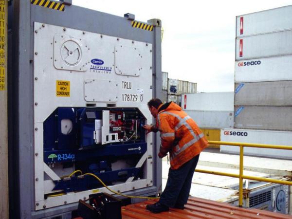
Рефрижераторный контейнер – средство для транспортировки и хранения скоропортящейся продукции, которая нуждается в создании определенных условий, касающихся температуры и влажности. Современное оборудование известных производителей отличается высокой надежностью, но для продления его срока службы необходимо соблюдать правила эксплуатации и техобслуживания. Своевременное техническое обслуживание тары с холодильной установкой снижает риск ее внезапного выхода из строя во время длительных перевозок грузов различными видами транспорта.
Электрообеспечение рефконтейнеров
При транспортировке группы модулей или при хранении на терминале в подключенном состоянии обязательным условием нормальной работы оборудования, и, следовательно, сохранности груза является обеспечение бесперебойного электроснабжения. Для этого следует правильно рассчитать необходимую мощность источника электропитания.
Пример:
- всего обслуживается – 20 агрегатов;
- одновременно работает – 75% от общего количества рефконтейнеров (15 штук);
- среднее энергопотребление одного агрегата – 10 кВт;
- характеристики сети электропитания – 380 В, 50 Гц, cos ȹ 0,78;
- коэффициент пиковой нагрузки – 1,2.
Расчеты:
- требуемая мощность = 20*0,75*10*1,2 = 180 кВт;
- требуемый ампераж тока = 180/(380*1,73*0,78)*1000 = 351 А.
Мероприятия по обслуживанию рефрижераторных контейнеров
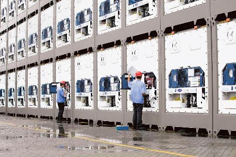
После каждой разгрузки на портовых терминалах и на железнодорожных станциях производят необходимые мероприятия по регулярному обслуживанию: мойку и дезинфекцию грузового отсека. Внутренние поверхности корпуса моют с использованием экологически и гигиенически безопасных составов, удаляющих жир и биологические загрязнения.
Техническое обслуживание рефконтейнеров должно производиться в условиях специализированных сервис-центров квалифицированными мастерами, имеющими в распоряжении современное диагностическое оборудование. Этапы технического обслуживания:
- На устройстве DataCORDER отображается информация за последние 90 дней работы установки, что позволяет установить отклонения от штатного режима, а следовательно, определить наиболее проблемные узлы рефконтейнера.
- Проверка целостности корпуса, надежности фиксации теплоизоляционных панелей и внутреннего металлического слоя.
- Диагностирование электрической части.
- Проверка состояния уплотнителей на двери.
- После определения работоспособности электронных компонентов и герметичности корпуса проводят диагностику на предмет утечек хладагента на стыках. Проверяют уровень масла, осматривают механические узлы. При необходимости – чистят трубопроводы.
- При необходимости производят подтяжку крепежных элементов, чистку и/или замену фильтров, замену шлангов.
Преимущества регулярного техобслуживания рефконтейнеров
Полноценное своевременное техническое обслуживание рефрижераторных контейнеров обеспечивает:
- диагностирование неполадок в системе;
- устранение мелких повреждений, которые впоследствии могли бы стать причиной крупных неисправностей, для их ликвидации нужен был бы дорогостоящий ремонт;
- продление срока службы рефрижератора.
Инструкция по эксплуатации рефконтейнеров Carrier, Thermo King, Star-Cool, Daikin
Все производители предоставляют максимально подробные инструкции по эксплуатации и обслуживанию рефрижераторных контейнеров.
Carrier
Thermo King
Star-Cool
Daikin
Категории из статьи перейти в Каталог
Рекомендуемые услуги перейти в Услуги
вернуться к списку статей
Руководства, описания, инструкции
Руководство пользователя Thermo King SL
SL-100e, SL-200e, SL-400e с SR-2 и SPECTRUM SL с SR-2
TK60057-2-OP (изд. 1, 08/06)
Авторефрижераторные установки с собственным двигателем TS-200, TS-300, TS-600, TS-500, SPECTRUM TS XDS SR, RD-II, KD-II, MD-200, MD-300, MD-II, SDZ, CD-II MAX UMD-II, URD-III, UTS, RD TLE, MD TLE, RD-MT, MD-MT, MD-200 MT Руководство пользователя
Авторефрижераторные установки с собственным
двигателем TS-200, TS-300, TS-600, TS-500, SPECTRUM TS XDS SR, RD-II, KD-II, MD-200, MD-300, MD-II, SDZ, CD-II MAX UMD-II, URD-III, UTS, RD TLE, MD TLE, RD-MT, MD-MT,
MD-200 MT
TK 60019-RU-1-OP (изд. 0)
Введение…………………………………………………………… 7
Руководство Пользователя Thermo King Старых Моделей Серии С
Руководство Пользователя Thermo King Старых Моделей Серии С
КНОПКИ И ИНДИКАТОРЫ УПРАВЛЕНИЯ
00 Световой индикатор включения; [2] Кнопка включения/выключения; [3) Световой индикатор заданной температуры; [4] Световой индикатор перегрузки по переменному току; [5] Световой индикатор работы установки; [б] Дисплей показаний температуры;0Световой индикатор показания температуры по Цельсию; [8]Световой индикатор показания температуры по Фаренгейту.
Руководство пользователя Thermo King Старых моделей серии V
Руководство пользователя Thermo King Старых моделей серии V
РАБОТА В РЕЖИМЕ ОТТАИВАНИЯ
РУЧНОЕ ВКЛЮЧЕНИЕ РЕЖИМА ОТГАИВАНИЯ*)
При нажатии кнопка ручного включения запускает режим оттаивания, если температура испарителя ниже 2°С или 35°F, при этом светодиод оттаивания должен включиться.
Установка будет работать в режиме охлаждения автоматически, когда цикл оттаивания закончится.
Руководство пользователя Direct Smart Reefer Thermo King Серии V
Руководство пользователя Direct Smart Reefer Thermo King Серии V
Установки с приводом от двигателя автомобиля и контроллером Direct Smart Reefer Руководство по эксплуатации B-100, V-100, V-200, V-300, V-400, V-500, V-700
РУССКИЙ содержание
Руководство оператора пульта управления ThermoGuard uP-T Smart Reefer
Руководство оператораThermoGuard TG-VI
Руководство оператораThermoGuard TG-VI
РАЗДЕЛ I
ПРАВИЛА БЕЗОПАСНОЙ ЭКСПЛУАТАЦИИ
Правила безопасности I-I
Общие правила I-I
Автоматический запуск/остановка I-I
Руководство пользователя Smart Reefer2
Руководство пользователя Smart Reefer2
ФУНКЦИИ ПУЛЬТА УПРАВЛЕНИЯ HMI
Пульт управления HMI (Human/Machine Interface) подключен к контроллеру и служит для управления агрегатом и отображения информации . Пульт HMI и контроллер соединены шиной CAN (Controller Area Network) . HMI также включает в себя регистратор данных о температуре груза Cargo Watch . Он расположен на дверце блока управления
Руководство оператора ThermoGuard Spectrum Multi-Temp
Раздел 1 — Информация по техникебезопасности SPECTRUM
Общие правила………………………………………………………………………………………………………………….. 1-1
Автоматический пуск и останов………………………………………………………………………………………… 1-1
Руководство пользователя SLX
SLX-100, 200 и 400 с контроллером SR-2
Введение
Общие сведения………………………………………………………………………………………………………………………………………………………………………….. 4
СЛУЖБА Thermo Assistance…………………………………………………………………………………………………………………………………………………………. 4
Коды ошибок Thermo King
Расшифровка кодов ошибок Thermo King (Термо Кинг)
Инструкции по эксплуатации органов управления Thermo King
Полезная информация о Thermo King

Помимо наличия универсальных систем воздушного потока и осушения для поддержания заданной температуры внутри, рефрижераторные транспортные контейнеры полностью защищены от атмосферных воздействий, поэтому нет риска испортить продукты, когда они достигнут места назначения. Не забывайте, что все контейнеры должны быть проверены перед поездкой (PTI) квалифицированным специалистом по рефрижераторам, чтобы гарантировать оптимальную работу устройства.

Благодаря правильному использованию и надлежащему обслуживанию ваш рефрижераторный транспортный контейнер может служить долгие годы при хранении или транспортировке скоропортящихся товаров. Однако важно, чтобы ваш рефрижератор использовался в соответствии с приведенными ниже рекомендациями, иначе вы рискуете потерять тысячи долларов на предметах, которые больше нельзя использовать, и/или поставить под угрозу свою безопасность.

Как их следует использовать?
Чтобы ваш рефрижераторный транспортный контейнер продолжал работать на максимальном уровне и минимизировать всевозможные риски во время эксплуатации, мы рекомендуем придерживаться следующих рекомендациям.

- Убедитесь, что ваш контейнер размещен на ровной поверхности, где он имеет достаточный приток воздуха, на расстоянии не менее одного метра от любой стены и вдали от прямых солнечных лучей. Об этом в видео на нашем youtube канале.
- Убедитесь, что рефрижератор правильно подключен к розетке 32 А, 415 В. Перед подключением к источнику питания осмотрите вилку кабеля на наличие следов пыли или воды.
- Загружайте продукт равномерно по всему контейнеру, следя за тем, чтобы не повредить защитную пластину перегородки и не ограничить поток воздуха на Т-образном дне контейнера, торце двери или возвратном воздухе.
- Соблюдайте осторожность и носите обувь с нескользящей резиновой подошвой при входе в контейнер или выходе из него.
- ЗАПРЕЩАЕТСЯ курить или использовать открытое пламя там, где присутствует хладагент.
- Убедитесь, что рефрижератор не загружается выше «предела красной линии» внутри контейнера.
- НИКОГДА не запускайте рефрижератор с открытыми дверями. Всегда выключайте контейнер ПЕРЕД ВХОДОМ. Перед началом работы убедитесь, что дверцы снова надежно закрыты.
- Ежемесячно промывайте змеевики рефрижераторного блока водой или воздухом.
- Регулярное техническое обслуживание, проводимое квалифицированным специалистом, обеспечивает эффективную работу и эффективность. Профилактическое обслуживание предотвратит простои и дорогостоящий ремонт.
- Безопасность при осмотре холодильного оборудования имеет решающее значение. Хладагент находится под высоким давлением, и в некоторых электрических цепях, помимо движущихся частей, может присутствовать высокое напряжение. НИКОГДА не открывайте блок управления без консультации с лицензированным электриком или специалистом по рефрижераторным установкам.
- Любые ремонтные работы должны выполняться лицом, знакомым с процедурами и рисками, связанными с личным здоровьем, пожарной безопасностью и безопасностью окружающей средой.
Если у вас возникнут сомнения, свяжитесь с нами по телефону 24/7
<8(812) 649-21-33
КОНТЕЙНЕР ЛИЗИНГ
Инструкция по эксплуатации рефконтейнера
TERMOKING SABRU модель ел 50825-4-ММ
Инструкция по эксплуатации
рефрижераторных контейнеров
SABRU “THERMO KING”
модели ТК 50825-4-ММ
Руководство по обслуживанию
| Перед каждым выключе-нием |
Каждые 1000 часов |
Ежегодно |
Проверка/обслуживание по следующим пунктам |
| Рефрижераторная часть | |||
| * |
* |
* |
Произвести полное тестирование контроллера перед выключением для проверки рефрижераторной и электрической систем
Произвести расширенное тестирование перед выключением |
| Электрическая часть | |||
| * * * |
* * * * |
* * * * * |
Визуальная проверка вращения вентилятора конденсатора и вентилятора испарителя
Визуальная проверка электрических контактов на наличие их повреждений или расшатанности Визуальная проверка электропроводки на наличие повреждений проводов или соединений Загрузка данных самописца и проверка данных для правильной регистрации данных Контрольная операция по проверке защитного отключения цепи |
| Конструктивная часть | |||
| * * |
* * * |
* * * |
Визуальная проверка установки на наличие поврежденных, неплотно сидящих или неисправных частей
Подтяжка крепежных болтов самой установки, компрессора, двигателя вентилятора Очистка полностью установки, включая змеевики конденсатора и испарителя и сливные отверстия оттайки. |
| Осушительная система | |||
| *
* |
* * |
* * |
Проверка уровня воды в водяной емкости
Проверки работы осушительной системы Очистка впускного водяного фильтра в водяной емкости |
Описание установки
Характеристика установки
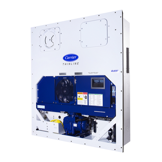
Установки моделей CSR PS и CSR PS+ являются полностью электрифицированными однокомпонентными рефрижераторными установками с нижней подачей вентиляционного воздуха. Каждая установка предназначена для использования на охлаждающих или нагревающих контейнерах при перевозках морем или по суше. Каждый агрегат монтируется на передней стенке контейнера.
Панели корпуса и перекрытий изготовлены из алюминия и покрыты антикоррозийным составом. Снимаемая дверца испарителя крепится на шарнирах, что обеспечивает легкость в обслуживании. Все составные части, за исключением змеевика испарителя и электрических нагревателей, могут быть заменены со стороны передней части агрегата. Полностью изолированная и герметичная рефрижераторная система облегчает эксплуатацию и обслуживание.
Каждый агрегат снабжен силовым кабелем 18,3 м рассчитанный на ток 460-380 В / 3 фазы/ 60-50 Гц. Для работы при токе с указанными характеристиками силовой кабель снабжен специальным штекером.
Каждый агрегат оборудован электромоторами, рассчитанными на ток 460-380 В / 3 фазы/ 60-50 Гц. Автоматическая система корректировки фаз обеспечивает надлежащую последовательность фаз тока при работе вентиляторов конденсатора и испарителя. Силовой кабель агрегата расположен внизу за контрольным ящиком в отделении конденсатора.
Характеристики агрегата включают также герметичный змеевик компрессора с жидкостной инжекторной системой; 2-х скоростные вентиляторы испарителя; систему обмена свежего воздуха; контроллер МР-3000 со встроенным регистратором данных.
Герметичный змеевик компрессора с жидкостной инжекторной системой охлаждения.
Рефрижераторный агрегат включает герметичный змеевик компрессора (одна стационарная деталь и одна – вращающаяся) с высокотемпературными предохранителями и предохранителями обеспечивающие подачу наружного воздуха при переизбытке внутреннего воздуха, а также рефрижераторную инжекторную систему.
Контроллер МР-3000
Контроллер МР-3000 объединяет в одном устройстве показания детализированного контроля за рефрижераторной системой, термостатом, цифровым термометром, индикатором неисправностей и регистратором данных.
Контроллер вмонтирован в хорошо защищенном от погодных условий, антикоррозийном огражденном боксе. Верхний дисплей LED с заглавными буквами обеспечивает легкое наблюдение за температурой сенсоров контроля (температурой впускного или выпускного вентиляционного воздуха). Нижний 4-х строчный 20-ти знаковый дисплей LCD показывает важные данные, включая заданную температуру, дерево Главного Меню контроллера и важные данные по использованию агрегата.
Шестнадцать кнопок общего назначения используются для ввода и выбора данных из меню контроллера; определения вида функциональных проверок и перед выключением; вводить новое заданное значение температуры; задавать режимы работы. Клавиатура обеспечивает и цифровой и текстовый ввод данных. Четыре специализированных кнопки обеспечивают быстрый ввод изменений заданной температуры, ручную установку оттайки, выбор отображения данных по впускному/выпускному воздушному потоку, выбор шкалы измерения температуры (С или F).
Стационарный индикатор в верхнем дисплее LED контроллера отображает данные о работе компрессора, оттайки, нагрева, внутреннем диапазоне отклонения температуры, возникновении неисправностей, уровне влажности, температуру впускного и выпускного воздушного потока.
Встроенный в контроллер регистратор данных записывает данные с температурных датчиков, а также снижение мощности в сети, неисправности, режимы работы, неисправности датчиков, изменения установок и отключения агрегата. Все записи регистратора данных хранятся в оперативной памяти, которая питается от батарейки.
Интервалы регистрации данных могут быть выбраны в диапазоне от 1 минуты до ½, 1, 2 или 4 часа. При выборе 1-часового интервала, память регистратора данных может сохранить информацию об около 680 сутках.
Часы регистратора данных установлены на время по Гринвичу. Все записи данных содержат время и дату; заданную температуру; температуру впускного и выпускного воздушных потоков. Все зарегистрированные значения температуры можно увидеть на нижнем дисплее LCD контроллера.
Двухскоростные вентиляторы испарителя (для моделей CSR PS)
Модели CSR PS имеют 2-х скоростные двигатели. Вентиляторы испарителя работают непрерывно, чтобы обеспечить циркуляцию воздуха внутри контейнера. Вентиляторы работают на высокой скорости для охлаждаемого груза при заданной температуре от -9,9С (14,1 F) и выше. При заданной температуре от –10,0С (14,0 F) и ниже вентиляторы испарителя работают на пониженной скорости для замороженного груза. Частота вращения вентилятора испарителя на пониженной скорости составляет половину от частоты вращения на высокой скорости.
Примечание: Если включен эконом – режим:
- для охлаждаемых грузов: вентиляторы испарителя работают на пониженной скорости, если температура в контейнере находится в диапазоне допустимого отклонения;
— для замороженных грузов: вентиляторы испарителя останавливаются при нулевом режиме; контроллер включает вентиляторы на пониженной скорости на 5 минут каждые 45 минут.
Система обмена наружного воздуха
Система обмена наружного воздуха удаляет вредные газы из контейнера при перевозке скоропортящихся грузов. Вентиляционное отверстие системы расположено над контрольным ящиком. Вентиляционное отверстие настраивается на перевозку различных видов грузов и разные заданные условия охлаждения. Вентиляционное отверстие должно быть плотно закрыто при хранении замороженных грузов.
Дополнительные функции агрегата
Усовершенствованная система управления вентиляцией наружным воздухом (AFAM)
Усовершенствованный микропроцессор системы управления наружным воздухом обеспечивает программный контроль за уровнем обмена наружного воздуха, программируемую длительность открытия вентиляционного отверстия, автоматическую блокировку вентиляции наружным воздухом при хранении замороженного груза, автоматическое закрытие вентиляционного отверстия, если температура наружного воздуха падает ниже заданного температурного режима в контейнере, а также регистрация данных об уровне обмена наружного воздуха и интервалах открытия вентиляционного отверстия.
Система AFAM включает модуль контроля за заслонкой, вентиляционную заслонку, калибровщик отверстия, вентиляционную решетку. Контроллер МР-3000 посылает сигнал на модуль контроля заслонки, чтобы она приняла необходимое положение. Контроллер можно также установить на интервал открытия вентиляционного отверстия до 72-х часов. Это позволяет снижать температуру скоропортящихся грузов. Система может настраиваться на скорость обмена наружного воздуха от 0 до 285 м³/час. Положение заслонки зависит от заданного значения уровня вентиляции и частоты тока в сети.
AFAM+ система контроля окружающего воздуха.
Усовершенствованный микропроцессор системы контроля за окружающим воздухом также обеспечивает программный контроль за уровнем О² и СО² в контейнере и регистрацию данных об уровне О² и СО².
Система AFAM+ состоит из сенсора газа, сенсорного фильтра, сенсорного вентиляционного отверстия, узла клапана снижения давления, одинарного очистительного отверстия, разделительной циркуляционной панели и соединительного кабеля. Контроллер может быть установлен на уровень О² в контейнере о 0 до 21% и уровень СО² от 0 до 25%.
Система контроля осушения.
Осушительная система понижает относительную влажность в контейнере до заданного значения. Контролируемый диапазон – от 50% до 99%, тогда как задавать значение относительной влажности можно в диапазоне от 0 до 99%.
Двойное напряжение.
Система двойного напряжения включает автотрансформатор 15кВ и силовой кабель длиной 18,3 м для обеспечения мощности 230-190В / 3 фазы/60-50 Гц. Силовой кабель хранится ниже контрольного ящика в отделении конденсатора.
15В–овый автотрансформатор повышает напряжение 230/190В до 460/380В. Автотрансформатор включает гнездо с характеристиками 460-380В/3 фазы/60-50 Гц.
Для работы с напряжением 230/190 В надо вставить штекер силового кабеля на 460-380 В в гнездо автотрансформатора. Затем вставьте штекер силового кабеля на 230/190 В в источник тока на 230/190В.
Система контроля влажности.
Дополнительная система контроля влажности увеличивает относительную влажность воздуха внутри контейнера до заданного значения. Контролируемый диапазон – от 50% до 99%, тогда как задавать значение относительной влажности можно в диапазоне от 0 до 99%.
Дополнительная функция записи температуры.
Некоторые модели термосамописцев могут быть установлены на агрегате. Каждый термосамописец приспособлен противостоять самым различным погодным воздействиям, включая высокую и низкую температуру окружающей среды, соленую воду, влажность, грибок, промышленные загрязнения, динамические воздействия при погрузке, дождь, песок, пыль.
- 31-дневный самописец Saginomonia имеет привод от электромотора, питаемого от элемента батарейки сроком эксплуатации 1 год;
- 31-дневный самописец Partlow механически приводится в действие от пружинного механизма;
- Сенсор только у самописца Saginomonia.
Модем дистанционного управления (RMM)
Модем дистанционного управления REFCON предназначен для дистанционного управления через силовой кабель. Высокоскоростная трансмиссия считывает всю информацию контроллера. Данные также могут быть восстановлены из памяти регистратора данных через высокоскоростную передачу.
Гнездо дистанционного управления (с 4-мя отверстиями)
Дополнительный соединитель дистанционного управления с 4-мя отверстиями обеспечивает сигналы 24 В для ламп параллельного соединения, которые указывают режим работы компрессора – охлаждение, оттайка, нахождение в диапазоне допустимого отклонения температуры.
Функции системы контроля атмосферы TRANSFRESH
Некоторые функции системы TRANSFRESH предназначены осуществлять индивидуальные запросы клиента. Система TRANSFRESH обеспечивает контроль атмосферы внутри контейнера. Контролируя температуру и атмосферу внутри контейнера, может быть снижен уровень дыхания фруктов и овощей. Это позволяет сохранить качество продукта на более длительное время.
- TRANSFRESH готов: в агрегате установлено необходимое оборудование для использования системы контроля атмосферы TRANSFRESH. Прилагаемые совместимые кабели А2 (питание/оттайка) и А3 (соединения) установлены заводским путем (без коннекторов).
- Полная функция TRANSFRESH: составляющие системы TRANSFRESН устанавливаются для работы системы контроля атмосферы TRANSFRESH. Дополнительно к кабелям А2 и А3 (с соединителями на заводе устанавливаются: безопасный корпус, безопасное заграждение с изоляционным блоком, одинарное впускное очистительное отверстие, трубопровод и газоочиститель (А5 с коннекторами). Очистительное отверстие включает в себя съемную заглушку для подачи в контейнер обновленного воздуха.
Термосамописец
Самописец температуры включает оборудование по использованию 4-х сенсоров температуры. Эти сенсоры позволяют регистрировать и записывать температуру в разных местах груза.
Конденсаторно-ресиверная водоохладительная емкость
Водоохладительная конденсаторно-ресиверная система позволяет осуществлять контроль на верхней и нижней заградительной обшивке агрегата. В входном отверстии водопровода установлен кран, регулирующий давление воды, который позволяет останавливать вентилятор для регулировки охлаждения воды в конденсаторе. Если давление воды, поступающей в конденсаторно-ресиверную емкость, больше, чем 117+/-21, 1.17+/- 0.21 бар, 17+/- 3 атм., кран регулирующий давление воды, перекрывается. Это дает сигнал контроллеру остановить работу вентилятора конденсатора.
Режимы работы.
Примечание: см. главу «Контроллер МР—3000, для получение информации о полной
последовательности операций.
Последовательная подача требуемой нагрузки вызывает начальный запуск агрегата, и после смещения контрольного режима запускается компрессор. Контроллер передает информацию о подаче нагрузки на агрегат, нижний LCD дисплей контроллера показывает заданную температуру. Верхний LED дисплей контроллера показывает температуру контрольных сенсоров. Показания контрольного сенсора определяется установленной температурой:
| Установленная температура | Контрольный сенсор |
| -9,9°С (14,1 F) и выше | Температура впускного воздуха |
| -10,0°С (14,0 F) и ниже | Температура выпускного воздуха |
Контроллер МР-3000 использует пропорционально-интегральный произвольный алгоритм для обеспечения точного контроля температуры. Таким образом, трудно предугадать в каком режиме работы будет находиться агрегат путем сравнения заданной температуры с температурой впускного или выпускного воздуха. Агрегат работает или на охлаждение или на заморозку. Точка температуры отделяющая охлаждение от заморозки – (-10°С/ 14 F).
Охлаждаемые грузы: установка контроллера на температуру -9,9°С (14,1 F) или выше
Контроль температуры контроллером осуществляется при помощи сенсора температуры впускного воздушного потока, заданных значений, диапазона изменения температуры и уровня вытяжки. Вентиляторы испарителя работают на высокой скорости (кроме режима оттайки).
- Режим охлаждения с модуляцией (согласно установке).
- Нулевой режим (вентиляторы конденсатора и компрессора стоят, вентиляторы испарителя работают).
- Режим нагрева (нагреватели сопротивления включены, вентиляторы испарителя работают).
- Режим оттайки (нагреватели сопротивления включены, вентиляторы испарителя отключены).
Примечание: Если включен экономичный режим, вентиляторы испарителя работают на пониженной
скорости при заданной температуре -9,9°С (14,1 F) или выше всякий раз, когда
температура в контейнере попадает в диапазон допустимого отклонения.
Замороженные грузы: установка контроллера на температуру -10,0°С (14,0 F) или ниже
Контроль температуры контроллером осуществляется при помощи сенсора температуры выпускного воздуха. Вентиляторы испарителя работают непрерывно на пониженной скорости (за исключением режима оттайки).
- Режим заморозки (температура на 1°С (1,8 F) ниже заданной).
- Нулевой режим (вентиляторы конденсатора и компрессора стоят, вентиляторы испарителя работают).
- Режим оттайки (нагреватели сопротивления включены, вентиляторы испарителя отключены).
Примечание: Если включен экономичный режим, вентиляторы испарителя останавливаются, когда
агрегат входит в нулевой режим. Контроллер автоматически включает вентиляторы
испарителя на пониженную скорость на 5 минут каждые 45 минут, пока агрегат
находится в нулевом режиме.
-
Contents
-
Table of Contents
-
Troubleshooting
-
Bookmarks
Quick Links
Container Refrigeration
OPERATIONS AND SERVICE
MANUAL
For
69NT40-541-500 to 599
Container Refrigeration Units
T-363 Rev C
Related Manuals for Carrier 69NT40-541-500
Summary of Contents for Carrier 69NT40-541-500
-
Page 1
Container Refrigeration OPERATIONS AND SERVICE MANUAL 69NT40-541-500 to 599 Container Refrigeration Units T-363 Rev C… -
Page 3
OPERATIONS AND SERVICE MANUAL 69NT40-541-500 to 599 © Carrier Corporation, 2017 Printed in U. S. A. December 2017… -
Page 5
TABLE OF CONTENTS Paragraph Number Page SAFETY SUMMARY …………..1–1 GENERAL SAFETY NOTICES . -
Page 6: Table Of Contents
DESCRIPTION …………… . 3–1 GENERAL DESCRIPTION .
-
Page 7
PRE-TRIP DIAGNOSTICS ……….. . . 4–15 DATACORDER . -
Page 8
UNIT WILL NOT TERMINATE HEATING ……… . . 6–2 UNIT WILL NOT DEFROST PROPERLY . -
Page 9
7.14 EVAPORATOR FAN AND MOTOR ASSEMBLY ……..7–21 7.14.1 Replacing the Evaporator Fan Assembly . -
Page 11
LIST OF ILLUSTRATIONS FIGURE NUMBER Page Figure 3.1 Refrigeration Unit — Front Section ……….3–1 Figure 3.2 Evaporator Section — Units with Center Access Panel . -
Page 12
Figure 7.23 Suction Modulation Valve (SMV) ……….7–25 Figure 7.24 Controller Section of the Control Box . -
Page 13
LIST OF TABLES TABLE NUMBER Page Table 3–1 Safety and Protective Devices ……….. . 3–8 Table 4–1 Keypad Function . -
Page 15
SECTION 1 SAFETY SUMMARY GENERAL SAFETY NOTICES Installation and servicing of refrigeration equipment can be hazardous due to system pressures and electrical com- ponents. Only trained and qualified service personnel should install, repair, or service refrigeration equipment. The following general safety notices supplement specific warnings and cautions appearing elsewhere in this man- ual. -
Page 16
WARNING EXPLOSION HAZARD: Failure to follow this WARNING can result in death, serious personal injury and / or property damage. Never use air or gas mixtures containing oxygen (O2) for leak testing or operating the product. Charge Only With R−134a: Refrigerant must conform to AHRI Standard 700 specification. WARNING Beware of unannounced starting of the evaporator and condenser fans. -
Page 17
WARNING Before disassembly of any external compressor component make sure to relieve possible internal pressure by loosening the bolts and tapping the component with a soft hammer to break the seal. CAUTION Do not remove wire harnesses from controller unless you are grounded to the unit frame with a static safe wrist strap. -
Page 18
The set screw on the crankshaft must be removed for this type of oil pump. (See Figure 6-8.) CAUTION Use only Carrier Transicold approved Polyol Ester Oil (POE) − Castrol-Icematic SW20 compres- sor oil with R-134a. Buy in quantities of one quart or smaller. When using this hygroscopic oil, immediately reseal. -
Page 19
INTRODUCTION INTRODUCTION The Carrier Transicold model 69NT40-541-500 to 599 series units are of lightweight aluminum frame construction designed to fit in the front of a container and serve as the container’s front wall. They are one piece, self-contained, all-electric units, which include cooling and heating systems to provide precise temperature control. -
Page 20
2.3.9 Evaporator Fan Operation Units are equipped with three-phase evaporator fan motors. Opening of an evaporator fan internal protector will shut down the unit. 2.3.10 Plate Set Each unit is equipped with a tethered set of wiring schematic and wiring diagram plates. The plate sets are ordered using a seven-digit base part number and a two-digit dash number. -
Page 21
For information on the TransFresh system, contact TransFresh Corporation, P.O. Box 1788, Salinas CA 93902 The EverFresh option is the addition of the Carrier Transicold EverFresh controlled atmosphere system. This sys- tem continuously monitors and controls oxygen and carbon dioxide levels in the container. -
Page 23: Description
SECTION 3 DESCRIPTION GENERAL DESCRIPTION 3.1.1 Refrigeration Unit — Front Section The unit is designed so the majority of the components are accessible from the front (see Figure 3.1). The unit model number, serial number, and parts identification number can be found on the serial plate to the left of the compressor. 3.1.2 Fresh Air Makeup Vent The function of the upper or lower makeup air vent is to provide ventilation for commodities that require fresh air circula-…
-
Page 24: Evaporator Section
3.1.3 Evaporator Section The evaporator section is shown below. The evaporator fans circulate air through the container by pulling it in the top of the unit, directing it through the evaporator coil where it is heated or cooled, and discharging it at the bottom. If the unit is equipped with eAutoFresh, system components are mounted in addition to the standard refrigeration unit components.
-
Page 25: Compressor Section
3.1.4 Compressor Section The compressor section includes the compressor (with high pressure switch), power cable storage compartment, and autotransformer. This section also contains the quench valve, suction modulating valve, discharge pressure regulating valve, discharge temperature sensor, and discharge/suction pressure transducers. The supply tempera- ture sensor, supply recorder sensor, and ambient sensor are located at the right side of the compressor.
-
Page 26: Air-Cooled Condenser Section
3.1.5 Air-Cooled Condenser Section The air-cooled condenser section (Figure 3.4) consists of the condenser fan, condenser coil, receiver with sight glass/ moisture indicator, quench valve, liquid line service valve, filter-drier, condenser pressure transducer, and fusible plug. The condenser fan pulls air from around the coil and discharges it horizontally through the condenser fan grille. Figure 3.4 Condenser Section 1.
-
Page 27: Control Box Section
3.1.6 Control Box Section The control box (Figure 3.5) includes the manual operation switches, circuit breaker (CB-1), compressor, fan and heater contactors, control power transformer, current sensor module, controller module and the communications interface module. 3.1.7 Communications Interface Module (option) The communications interface module is a slave module which allows communication between the refrigeration unit and a ship system master central monitoring station.
-
Page 28: Refrigeration System Data
REFRIGERATION SYSTEM DATA Number of Cylinders Model 06DR Weight (Dry) 118kg (260 lb) a. Compressor/Motor Assembly Approved Oil Castrol Icematic Oil Charge degrees 3.6 liters (7.6 U.S. pints) Oil Sight Glass The oil level range, with the compressor off, should be between the bottom and one-eighth level of the sight glass.
-
Page 29: Electrical Data
ELECTRICAL DATA CB-1 Trips at 29 amps a. Circuit Breaker CB-2 (50 amps) Trips at 62.5 amps CB-2 (70 amps) Trips at 87.5 amps 17.6 amps @ 460 VAC b. Compressor Motor Full Load Amps (FLA) (with current limiting set at 21 amps) Nominal Supply 380 VAC, Three Phase, 460 VAC, Three Phase,…
-
Page 30: Safety And Protective Devices
ELECTRICAL DATA (Continued) Orange wire Power Red wire Output Brown wire Ground Input voltage 5 vdc Output voltage 0 to 3.3 vdc h. Humidity Sensor Output voltage readings verses relative humidity (RH) percentage: 0.99V 1.65V 2.31V 2.97V i. Controller Setpoint Range -30 to +30°C ( -22 to +86°F) SAFETY AND PROTECTIVE DEVICES Unit components are protected from damage by safety and protective devices listed in the following table.
-
Page 31: Refrigeration Circuit
REFRIGERATION CIRCUIT Starting at the compressor (see Figure 3.6), the suction gas is compressed to a higher pressure and temperature. The gas flows out the compressor through the discharge service valve. Refrigerant gas then moves into the air- cooled condenser, where air flowing across the coil fins and tubes cools the gas to saturation temperature. By removing latent heat, the gas condenses to a high pressure/high temperature liquid and flows to the receiver, which stores the additional charge necessary for low temperature operation.
-
Page 32: Figure 3.6 Refrigeration Circuit Schematic
Figure 3.6 Refrigeration Circuit Schematic Refrigeration Circuit with Receiver EVAPORATOR TXV BULB THERMOSTATIC EXPANSION VALVE (TXV) CONDENSER HEAT EXCHANGER FUSIBLE PLUG SIGHT GLASS FILTER SIGHT GLASS / QUENCH VALVE MOISTURE DRIER INDICATOR LIQUID LINE RECEIVER VALVE DISCHARGE QUENCH VALVE BULB SERVICE VALVE SUCTION…
-
Page 33: Microprocessor
SECTION 4 MICROPROCESSOR TEMPERATURE CONTROL MICROPROCESSOR SYSTEM The temperature control Micro-Link 3 microprocessor system (see Figure 4.1) consists of a keypad, display mod- ule, control module (controller), and interconnecting wiring. The controller houses the temperature control software and the DataCORDER Software. The temperature control software functions to operate the unit components as required to provide the desired cargo temperature and humidity.
-
Page 34: Keypad
4.1.1 Keypad The keypad (Figure 4.2) is mounted on the control box door. The keypad consists of 11 push button switches that act as the user’s interface with the controller. Descriptions of the switch functions are provided in Table 4–1. Figure 4.2 Keypad CODE SELECT…
-
Page 35: Controller
Table 4–1 Keypad Function FUNCTION CODE SELECT Accesses function codes. PRE TRIP Displays the pre-trip selection menu. Discontinues pre-trip in progress. ALARM LIST Displays alarm list and clears the alarm queue. MANUAL DEFROST / Displays selected defrost mode. Depressing and holding the Defrost interval key for five seconds will initiate defrost using the same logic INTERVAL as if the optional manual defrost switch was toggled on.
-
Page 36: Controller Software
CAUTION Do not attempt to use an ML2i PC card in an ML3 equipped unit. The PC cards are physically different and will result in damage to the controller. NOTE Do not attempt to service the controller. Breaking the seal will void the warranty. The Micro-Link 3 controller is a single module microprocessor as shown in Figure 4.4.
-
Page 37: Operational Software (Cd Function Codes)
4.2.2 Operational Software (Cd Function Codes) The operational software is the actual operation programming of the controller which activates or deactivates com- ponents in accordance with current unit operation conditions and selected modes of operation. The programming is divided into function codes. Some of the codes are read only, while the remaining codes may be user configured.
-
Page 38: Perishable Idle, Air Circulation
4.3.4 Perishable Idle, Air Circulation Perishable Idle Mode is used when it is unnecessary to run the compressor to maintain control temperature. If the controller has determined that cooling is not required or the controller logic determines suction pressure is at the low pressure limit, the unit will transition to Perishable Idle Mode.
-
Page 39: Perishable, Dehumidification — Bulb Mode
If the above conditions remain true for at least one hour, the evaporator fans will switch from high speed to low speed. Evaporator fan speed will then switch every hour, as long as the 4 conditions are met (see Bulb Mode, Section 4.3.7 for different evaporator fan speed options).
-
Page 40: Perishable Mode Cooling — Sequence Of Operation
After the initial three minutes, they will then be switched to low speed any time supply air temperature is within +/- 0.25°C (0.45°F) of set point and return air temperature is less than or equal to supply air temperature +3°C (5.4°F). The fans will continue to run in low speed for one hour.
-
Page 41: Perishable Mode Heating — Sequence Of Operation
4.3.10 Perishable Mode Heating — Sequence of Operation NOTE The unit will heat only when in the Perishable Mode, relay TH is electronically locked out when in the Frozen Mode. a. If the supply air temperature decreases 0.5°C (0.9°F) below set point, the system enters the heating mode (see Figure 4.5).
-
Page 42: Frozen Idle Mode
Figure 4.8 Controller Operation — Frozen Mode Frozen Mode Controller Set Point at or BELOW 10 C (+14 F), or 5 C (+23 F) optionally +2.5 C (+4.5 F) Cooling +.20 C Set Point .20 C Air Circulation Falling Rising Temperature Temperature 4.3.13…
-
Page 43: Frozen Mode Cooling — Sequence Of Operation
After an off-cycle period of 60 minutes, the unit will turn on high speed evaporator fans for three minutes and then check the control temperature. If the control temperature is greater than or equal to the frozen set point +0.2°C (0.36°F), the unit will restart the refrigeration system and continue to cool until the previously mentioned off-cycle temperature criteria are met.
-
Page 44: Defrost Operation
If defrost was initiated by the probe check logic, then a Probe Check is carried out after the completion of the defrost cycle. A Probe Check is initiated only when there is an inaccuracy between the controller temperature sensors. For more information on Probe Check refer to Section 5.9.
-
Page 45: Defrost Related Settings
When defrost is initiated, the controller closes the SMV, opens contacts TC, TN and TE (or TV) to de-energize the compressor, condenser fan and evaporator fans. The controller then closes contacts TH to supply power to the heaters. The orange DEFROST light and heat light are illuminated and the COOL light is also de-energized.
-
Page 46: Protection Modes Of Operation
If CnF64 is configured in the operator will be allowed to choose “PuLS” as a defrost interval option. For units operating with “PuLS” selected, defrost interval is determined by the unit temperature setpoint and the Evaporator Fan Pulsing Temperature Setting (Cd60). When the unit temperature setpoint is equal to or less than the Evaporator Fan Pulsing Temperature Setting, the defrost interval is set to 6 hours.
-
Page 47: Controller Alarms
CONTROLLER ALARMS Alarm display is an independent controller software function. If an operating parameter is outside of expected range or a component does not return the correct signals back to the controller, an alarm is generated. A listing of the alarms is provided in Table 4–6.
-
Page 48: Datacorder
5.8. DATACORDER The Carrier Transicold “DataCORDER” software is integrated into the controller and serves to eliminate the tem- perature recorder and paper chart. DataCORDER functions may be accessed by keypad selections and viewed on the display module. The unit is also fitted with interrogation connections (see Figure 4.1).
-
Page 49: Datacorder Software
A list of the data points available for recording follows. Changing the configura- tion to generic and selecting which data points to record may be done using the Carrier Transicold Data Retrieval Pro- gram.
-
Page 50: Logging Interval (Dcf03)
9. Suction modulation valve percentage 10. Discrete outputs (See Note ) 11. Discrete inputs (See Note ) 12. Ambient sensor 13. Compressor suction sensor 14. Compressor discharge sensor 15. Return temperature sensor 16. Supply temperature sensor 17. Defrost temperature sensor 18.
-
Page 51: Figure 4.11 Standard Configuration Report
Figure 4.11 Standard Configuration Report Raw Data Report for ABCU1234567 Aug 22, 2012 to Sept 05, 2012 System Configuration at the Time of Interrogation: Interrogated On Sept 05, 2012 Extracted by DataLine Rev 2.1 Controller Software: 5154 Controller Serial #: 04163552 Bill of Lading #: 1 Origin: Origin Date:…
-
Page 52: Sampling Type (Dcf05 & Dcf06)
Table 4–3 Data CORDER Standard Configurations STANDARD CONFIG DESCRIPTION 2 sensors (dCF02=2) 2 thermistor inputs (supply & return) 2 thermistor inputs (supply & return) 5 sensors (dCF02=5) 3 USDA thermistor inputs 2 thermistor inputs (supply & return) 6 sensors (dCF02=6) 3 USDA thermistor inputs 1 humidity input 9 sensors (dCF02=9)
-
Page 53: Pre-Trip Data Recording
In response to the demand to replace fumigation with this environmentally sound process, Carrier has integrated Cold Treatment capability into its microprocessor system. These units have the ability to maintain supply air tem- perature within one-quarter degree Celsius of setpoint and record minute changes in product temperature within the DataCORDER memory, thus meeting USDA criteria.
-
Page 54: Usda Cold Treatment Procedure
The standard DataCORDER report displays the supply and return air temperatures. The cold treatment report displays USDA #1, #2, #3, and the supply and return air temperatures. Cold treatment recording is backed up by a battery so recording can continue if AC power is lost. b.
-
Page 55: Iso Trip Header
d. “END” is displayed to indicate the end of the alarm list if any alarms are active. “CLEAr” is displayed if all the alarms in the list are inactive. e. If no alarms are active, the Alarm Queue may be cleared. The exception to this rule is the DataCORDER Alarm Queue Full alarm (AL91), which does not have to be inactive in order to clear the alarm list.
-
Page 56: Controller Configuration Variables
CONTROLLER CONFIGURATION VARIABLES Table 4–4 Controller Configuration Variables CONFIGURATION TITLE DEFAULT OPTION NUMBER CnF01 Bypass Valve Enable 0-in, 1-out CnF02 Evaporator Fan Speed dS (Dual) 0-single, 1-dual CnF03 Control Sensors FOUr (quad) 0-duAL, 1-quad CnF04 Dehumidification Mode 0-on, 1-off CnF07 Unit Selection, 20FT/ 40FT/45FT 40ft 0-40ft, 1-20ft, 2- 45ft…
-
Page 57
Table 4–4 Controller Configuration Variables (Continued) CONFIGURATION TITLE DEFAULT OPTION NUMBER CnF40 Demand Defrost 0-Out 1-in CnF41 Lower DTT Setting 0-Out 1-in CnF42 Enable Auto Pretrip Start 0-Out 1-in CnF43 Pulldown Defrost 0-Out 1-in CnF44 Autoslide Enabled 0-Out 1-Lo, 2-Up CnF45 Low Humidity Enabled 0-Out… -
Page 58: 4.10 Controller Function Codes
4.10 CONTROLLER FUNCTION CODES Table 4–5 Controller Function Codes CODE TITLE DESCRIPTION Note: If the function is not applicable, the display will read “——” Display Only Functions — Cd01 through Cd26 are display only functions. Suction Modulation Displays the SMV percent open. The right display reads 100% when the valve is Cd01 Valve (SMV) fully open and 0% when the valve is fully closed.
-
Page 59
Table 4–5 Controller Function Codes (Continued) CODE TITLE DESCRIPTION This code checks the Controller/DataCORDER battery pack. While the test is run- ning, “btest” will flash on the right display, followed by the result. PASS will be dis- played for battery voltages greater than 7.0 volts. FAIL will be displayed for battery Cd19 Battery Check voltages between 4.5 and 7.0 volts, and —— will be displayed for battery voltages… -
Page 60
Table 4–5 Controller Function Codes (Continued) CODE TITLE DESCRIPTION Configurable Functions Configurable Functions — Cd27 through Cd37 are user-selectable functions. The operator can change the value of these functions to meet the operational needs of the container. There are two modes for defrost initiation, either user-selected timed intervals or automatic control. -
Page 61
Table 4–5 Controller Function Codes (Continued) CODE TITLE DESCRIPTION The in-range tolerance will determine the band of temperatures around the set point which will be designated as in-range. For normal temperature control, control temperature is considered in range if it is within setpoint In-Range Tolerance. -
Page 62
Table 4–5 Controller Function Codes (Continued) CODE TITLE DESCRIPTION This is the desired evaporator fan speed for use during the bulb Dehumidification and Humidification mode option. (Replaced by Cd48 if CnF50, Enhanced Bulb Mode, is active.) This code is enabled only if in the dehumidification mode (Cd33) and bulb mode (Cd35) has been set to bulb. -
Page 63
Table 4–5 Controller Function Codes (Continued) CODE TITLE DESCRIPTION Configurable Functions — Cd43 is a user-selectable function. The operator can change the value of this function to meet the operational needs of the container. Cd43 is a user selectable mode of operation that allows opening and closing of a mechanical air vent door via a stepper motor. -
Page 64
Table 4–5 Controller Function Codes (Continued) CODE TITLE DESCRIPTION Initially Cd48 will display current dehumidification-mode; bUlb — bulb cargo mode, dEhUM — normal dehumidification, or OFF — off. This display is steady. Pressing ENTER key will take the interface down into a hierarchy of parameter se- lection menus (mode, setpoint, evaporator speed, DTT setting). -
Page 65
Table 4–5 Controller Function Codes (Continued) CODE TITLE DESCRIPTION Configurable Functions — Cd50 through Cd53 are user-selectable functions. The operator can change the value of these functions to meet the operational needs of the container. «OFF» = disabled. «On» = enabled. «SEtPt»… -
Page 66
Table 4–5 Controller Function Codes (Continued) CODE TITLE DESCRIPTION ASC-mode: Cd53 increments of (1 day)_(1hr), Display: default 0_0 done mm-dd this will be display is ASC has completed ASC value “On” “OFF” Display /Select: default OFF nSC value “1 — 6” (This is the value n for the subsequent entries). SP (n-1) value °C/°F on 0.1 degree increments Display/Select: default 10.0°C DAY (n-1) value “1-99”… -
Page 67: Figure 4.12 Alarm Troubleshooting Sequence
Figure 4.12 Alarm Troubleshooting Sequence Start Troubleshooting Check Power Refer to Connect Power, Section 5.2 Unit does Supply self test? Check Power Refer to Connect Power, Section 5.2 Evaporator Supply fans start? Correct Install Latest Refer to Controller Software, Section 4.2 software Software version?
-
Page 68: 4.11 Controller Alarm Indications
4.11 CONTROLLER ALARM INDICATIONS AL05 MANUAL DEFROST SWITCH FAILURE Cause: Controller has detected continuous Manual Defrost Switch activity for five minutes or more. Component Keypad Troubleshooting Power cycle the unit. Corrective Action Resetting the unit may correct problem, monitor the unit. If the alarm reappears after 5 minutes replace the keypad.
-
Page 69
AL12 EVAPORATOR FAN 2 IP Cause: Alarm 12 is triggered when configured for single evap operation and KB10 sensed high. Component Evaporator Fan 2 Troubleshooting The unit will suspend probe check diagnostic logic and disable the probe check portion of defrost cycle. Corrective Action AL12 is triggered off when KB10 sensed low. -
Page 70
AL21 CONTROL CIRCUIT FUSE (F1/F2) Cause: One of the 18 VAC controller fuses (F1/F2) is open. Refer to Cd08. Component System Sensors Troubleshooting Check system sensors for short to ground. Corrective Action Replace defective sensor(s). Component Wiring Troubleshooting Check wiring for short to ground. Corrective Action Repair as needed. -
Page 71
AL25 CONDENSER IP Cause: Condenser fan motor internal protector (IP) is open. Component Insufficient Air Flow Troubleshooting Shut down unit and check condenser fan for obstructions. Corrective Action Remove obstructions. Component Condenser Fan Motor Troubleshooting Shut down unit, disconnect power, & check Condenser Fan Motor IP at plug connection pins 4 &… -
Page 72
AL50 AIR VENT POSITION SENSOR (VPS) Cause: VPS Sensor out of range. Component Vent Position Sensor (VPS) Troubleshooting Make sure VPS is secure. Corrective Action Manually tighten panel. Component Vent Position Sensor (VPS) Troubleshooting If the alarm persists, replace the sensor or the assembly. Corrective Action Replace VPS. -
Page 73
AL54 PRIMARY SUPPLY SENSOR (STS) Cause: Invalid Supply Temperature Sensor (STS) reading. Component Supply Temperature Sensor (STS) Troubleshooting Perform Pre-trip P5: Corrective Action If P5 passes, no further action is required. If P5 fails, replace the defective sensor as determined by P5. Refer to Tem- perature Sensor Service, Section 7.21. -
Page 74
AL59 HEATER TERMINATION THERMOSTAT (HTT) Troubleshooting Check for 24 volts at test point TP10. If no voltage at TP10 after unit has reached set point, HTT is open. Corrective Action Replace HTT if defective. AL60 DEFROST TEMPERATURE SENSOR (DTS) Cause: Failure of the Defrost Temperature Sensor (DTS) to open. Component Defrost Temperature Sensor (DTS) Troubleshooting Test the DTS. -
Page 75
AL63 CURRENT LIMIT Component Current limit set too low Troubleshooting Check current limit setting Code Cd32. Corrective Action The current limit can be raised (maximum of 23 amps) using Cd32. AL64 DISCHARGE TEMPERATURE SENSOR (CPDS) Cause: Discharge Temperature sensor out of range. Component Discharge temperature sensor (CPDS) Troubleshooting Test the CPDS. -
Page 76
AL68 CPC PRESSURE SENSOR (PS3) Cause: Condenser Pressure Transducer (CPC) out of range. Component Condenser Pressure Transducer (CPC) Troubleshooting NA Corrective Action Unit will disable Condenser Pressure Control if configured. AL69 SUCTION TEMP SENSOR (CPSS) Cause: Suction Temperature Sensor (CPSS) out of range. Component Suction Temperature Sensor (CPSS) Troubleshooting Test the CPSS. -
Page 77: Table 4-6 Controller Alarm Indications
Table 4–6 Controller Alarm Indications NOTE If the controller is configured for four probes without a DataCORDER, the DataCORDER alarms AL70 and AL71 will be processed as Controller alarms AL70 and AL71. Refer to Table 4–10. The controller performs self-check routines. If an internal failure occurs, an ERR alarm will appear on the display.
-
Page 78: 4.12 Controller Pre-Trip Test Codes
4.12 CONTROLLER PRE-TRIP TEST CODES Table 4–7 Controller Pre-Trip Test Codes NOTE Auto or Auto1 menu includes the: P, P1, P2, P3, P4, P5, P6 and rSLts. Auto2 menu includes P, P1, P2, P3, P4, P5, P6, P7, P8, P9, P10 and rSLts.Auto3 menu includes P, P1, P2, P3, P4, P5, P6, P7, P8 and rSLts Container identifier code, Cd18 Software Revision Number, Cd20 Container Unit Model Number, &…
-
Page 79
Table 4–7 Controller Pre-Trip Test Codes P4 Tests — High Speed Evaporator Fans Current Draw: High speed evaporator fans are turned on, then off. Current draw must fall within specified range and measured current changes must exceed specified ratios. No other system components will change state during this test. -
Page 80
Table 4–7 Controller Pre-Trip Test Codes P5-4 — P5-9 Not Applicable This is a Pass/Fail/Skip test of the humidity sensor configuration. Test passes if the controller configuration has humidity sensor in. Humidity Sensor Test fails if the controller configuration has humidity sensor out and Vout is greater Controller P5-10 than 0.20 Volts for the humidity sensor. -
Page 81
Table 4–7 Controller Pre-Trip Test Codes P7 Tests — High Pressure Tests: Unit is run at full capacity without condenser fan running to make sure that the HPS opens and closes properly. With the unit running, the condenser fan is de-energized, and a 15 minute timer is started. -
Page 82
Table 4–7 Controller Pre-Trip Test Codes Control temperature must be at least 15.6C (60F). The set point is changed to 0C (32F), and a 180-minute timer is started. The left display will read P81, the right display will show the supply air temperature. The unit will then start to pull down the temperature to the 0C set point. -
Page 83
Table 4–7 Controller Pre-Trip Test Codes P10 Tests — Frozen Mode Tests: After completion of the Defrost Test, if the container temperature is below 7.2C, the setpoint is changed to 7.2C, and a 180 minute timer is started. The control will then be placed in the equivalent of normal heating. -
Page 84: Table 4-8 Datacorder Function Code Assignments
Table 4–8 DataCORDER Function Code Assignments NOTE Inapplicable Functions Display “——” To Access: Press ALT. MODE key then CODE SELECT key CODE TITLE DESCRIPTION Recorder Supply Current reading of the supply recorder sensor. Temperature Recorder Return Current reading of the return recorder sensor. Temperature dC3-5 USDA 1,2,3 Temperatures Current readings of the three USDA probes.
-
Page 85: Table 4-9 Datacorder Pre-Trip Result Records
Table 4–9 DataCORDER Pre-Trip Result Records TEST TITLE DATA Heater On Pass/Fail/Skip Result, Change in current for Phase A, B and C Heater Off Pass/Fail/Skip Result, Change in currents for Phase A, B and C Pass/Fail/Skip Result, Water pressure switch (WPS) — Open/ Condenser Fan On Closed, Change in currents for Phase A, B and C Condenser Fan Off…
-
Page 86: Table 4-10 Datacorder Alarm Indications
Table 4–10 DataCORDER Alarm Indications To Access: Press ALT. MODE key then ALARM LIST key CODE TITLE DESCRIPTION dAL70 Recorder Supply The supply recorder sensor reading is outside of the range of 50 to 70C Temperature Out of (58F to +158F) or, the probe check logic has determined there is a fault Range with this sensor.
-
Page 87: Operation
SECTION 5 OPERATION INSPECTION (BEFORE LOADING) WARNING Beware of unannounced starting of the evaporator and condenser fans. The unit may cycle the fans and compressor unexpectedly as control requirements dictate. a. If container is empty, check inside for the following: 1.
-
Page 88: Adjust Fresh Air Makeup Vent
1. Make sure that the start-stop switch (ST, on control panel) and circuit breakers CB-1 (in the control box and CB-2 (on the transformer) are in position “O” (OFF). Plug in and lock the 460VAC power plug at the recepta- cle on the transformer.
-
Page 89: Vent Position Sensor
Figure 5.2 Make Up Air Flow Chart AIR FLOW AIR FLOW (CMH) 60HZ (CMH) 50HZ TBAR TBAR 1 1/2” 1 1/2” TBAR TBAR 2 5/8” 2 5/8” TBAR 3” TBAR 3” 90 100 90 100 PERCENT OPEN PERCENT OPEN 5.3.2 Vent Position Sensor The VPS allows the user to determine position of the fresh air vent via Cd45.
-
Page 90: Eautofresh Pre-Trip Inspection
5.4.1 eAutoFresh Pre-Trip Inspection Pre-trip testing of the eAutoFresh system is performed during Pre-Trip test P0. Operation of the system may be observed during this test. Upon initiation of Pre-Trip P0, the current state will be saved and the vent will fully close. This will be followed by two sequences of opening to 100% and returning to the closed position.
-
Page 91: Connect Remote Monitoring Receptacle
To set the unit in Delay mode, scroll until “DELAY“ appears in the left window, press the ENTER key to activate the submenu. The first selection is the amount of time (tIM) for the delay. Select the amount of time for the delay by using the UP and DOWN arrow keys.
-
Page 92: Starting And Stopping Instructions
STARTING AND STOPPING INSTRUCTIONS WARNING Make sure that the unit circuit breaker(s) (CB-1 & CB-2) and the START-STOP switch (ST) are in the “O” (OFF) position before connecting to any electrical power source. 5.6.1 Starting the Unit a. With power properly applied, the fresh air vent in proper position, place the START-STOP switch to “I” (ON), Figure 3.5.
-
Page 93
Pre-Trip diagnostics provides automatic testing of the unit components using internal measurements and compari- son logic. The program will provide a “PASS” or “FAIL” display to indicate test results. The testing begins with access to a Pre-trip selection menu. The user may have the option of selecting one of three automatic tests. -
Page 94: Probe Diagnostics
If configuration variable CnF42 is set to IN, a DataCORDER trip start will be entered. If CnF42 is set to OUT, the trip start will not be entered. However, dehumidification and bulb mode must be reactivated manually if required. c. TO RUN AN INDIVIDUAL TEST: Scroll through the selections by pressing the UP ARROW or DOWN ARROW keys to display an individual test code.
-
Page 95: Emergency Bypass Operation (Option)
5.10 EMERGENCY BYPASS OPERATION (OPTION) Operation by the refrigeration controller may be overridden by use of the EMERGENCY BYPASS switch. The EMERGENCY BYPASS switch functions to bypass the controller in the event of controller failure. To place the unit in the emergency bypass mode, cut the wire tie installed at the switch mounting and place the EMERGENCY BYPASS switch in the BYPASS position.
-
Page 97: Troubleshooting
SECTION 6 TROUBLESHOOTING UNIT WILL NOT START OR STARTS THEN STOPS Condition Possible Cause Remedy/Refer- ence Section External power source OFF Turn on Start-Stop switch OFF or defective Check No power to unit Circuit breaker tripped or OFF Check Autotransformer not connected 5.2.2 Circuit breaker OFF or defective Check…
-
Page 98: Unit Runs But Has Insufficient Cooling
UNIT RUNS BUT HAS INSUFFICIENT COOLING Condition Possible Cause Remedy/Refer- ence Section Compressor Compressor valves defective Abnormal pressures Controller malfunction Evaporator fan or motor defective 7.14 Refrigeration System Suction modulation valve malfunction 7.17 Condenser Pressure Transducer defective Check Shortage of refrigerant 7.7.1 UNIT WILL NOT HEAT OR HAS INSUFFICIENT HEATING Condition…
-
Page 99: Unit Will Not Defrost Properly
UNIT WILL NOT DEFROST PROPERLY Condition Possible Cause Remedy/Refer- ence Section Defrost timer malfunction (Cd27) Table 4–5 Loose terminal connections Tighten Will not initiate defrost Defective wiring Replace automatically Defrost temperature sensor defective or heat termination Replace thermostat open Heater contactor or coil defective Replace Manual defrost switch defective Replace…
-
Page 100: Abnormal Noise Or Vibrations
ABNORMAL NOISE OR VIBRATIONS Condition Possible Cause Remedy/Refer- ence Section Loose mounting bolts Tighten Worn bearings Compressor Worn or broken valves Liquid slugging 7.16 Insufficient oil 7.8.6 Bent, loose or striking venturi Check Condenser or Evaporator Fan Worn motor bearings 7.11/7.14 Bent motor shaft 7.11/7.14…
-
Page 101: 6.11 Eautofresh Not Operating
6.11 EAUTOFRESH NOT OPERATING Condition Possible Cause Remedy/Refer- ence Section Unit not Configured for eAutoFresh Operation No action Cd43 in Off mode 5.4.2 Wiring disconnected Check wiring Vent not opening Stepper drive defective 7.23.2 Stepper motor defective 7.23.2 Unit operating in frozen mode 5.4.3 Check CO sensor…
-
Page 103: Service
SECTION 7 SERVICE NOTE Use a refrigerant recovery system whenever removing refrigerant. When working with refrigerants you must comply with all local government environmental laws. In the U.S.A., refer to EPA section 608. WARNING EXPLOSION HAZARD: Failure to follow this WARNING can result in death, serious personal injury and / or property damage.
-
Page 104: Service Valves
A R-134a manifold gauge/hose set with self-sealing hoses (see Figure 7.2) is required for service of the models covered within this manual. The manifold gauge/hose set is available from Carrier Transicold. (Carrier Transicold P/N 07-00294-00, which includes items 1 through 6, Figure 7.2).
-
Page 105: Pump The Unit Down
Figure 7.3 Service Valve 1. Line Connection 5. Compressor or Filter Drier Inlet Connection 2. Access Valve 6. Valve (Frontseated) 3. Stem Cap 7. Valve (Backseated) 4. Valve stem — — — — — Connection of the manifold gauge/hose set (see Figure 7.4) is dependent on the component being serviced.
-
Page 106: Refrigerant Leak Checking
Essential tools to properly evacuate and dehydrate any system include a vacuum pump (8m-/hr = 5cfm vol- ume displacement) and an electronic vacuum gauge. The pump is available from Carrier Transicold, P/N 07-00176-11. The micron gauge is P/N 07-00414-00.
-
Page 107: Complete System
Figure 7.4 Refrigeration System Service Connections 1. Discharge Service Valve 8. Center Hose 2. Compressor 9. High Side Hose 3. Suction Service Valve 10. Electronic Vacuum Gauge 4. Receiver or Water Cooled Condenser 11. Manifold Gauge Set 5. Liquid Service Valve 12.
-
Page 108: Procedure — Partial System
7.6.4 Procedure — Partial System a. If the refrigerant charge has been removed from the compressor for service, evacuate only the compressor by connecting the evacuation set-up at the compressor service valves. Follow evacuation procedures of the preceding paragraph except leave compressor service valves frontseated until evacuation is completed. b.
-
Page 109: Adding Refrigerant To System (Partial Charge)
7.7.3 Adding Refrigerant to System (Partial Charge) a. Examine the unit refrigerant system for any evidence of leaks. Repair as necessary (refer to Section 7.5). b. Maintain the conditions outlined in Section 7.7.1. c. Fully backseat the suction service valve and remove the service port cap. d.
-
Page 110: Figure 7.5 Compressor
Figure 7.5 Compressor 1. Discharge Valve Flange 9. Oil Drain Plug 2. High Side Pressure Connection 10. Oil Charging Valve 3. Low Side Pressure Connection 11. Bearing Head 4. Suction Valve Flange 12. Oil Pump 5. Motor End Cover 13. Oil Fill Plug 6.
-
Page 111: Compressor Disassembly
7.8.2 Compressor Disassembly WARNING Before disassembly of any external compressor component make sure to relieve possible internal pressure by loosening the bolts and tapping the component with a soft hammer to break the seal. WARNING Removing the compressor motor press-fit stator in the field is not recommended. The rotor and stator are a matched pair and should not be separated.
-
Page 112: Figure 7.8 Oil Pump And Bearing Head
b. Loosen cylinder head cap screws. If the cylinder head is stuck, tap the center of the cylinder head with a wooden or lead mallet. Do not strike the side of the cylinder head. Be careful not to drop the head or damage the gasket sealing surface.
-
Page 113: Figure 7.9 Low Profile Oil Pump
Figure 7.9 Low Profile Oil Pump 1. Cap screws 7. O-Ring 2. Cover 8. Oil Pump & Bearing 3. Reversing Assembly 9. Set Screw 4. Pinion 10. Relief Valve 5. Gear 11. Pin 6. Drive 12. Gasket — — — — — h.
-
Page 114: Figure 7.11 Equalizing Tube And Lock Screw Assembly
Block the compressor crankshaft so that it cannot turn. Use a screwdriver to bend back the tabs on the lock- washer, and remove the equalizer tube and lock screw assembly (see Figure 7.11). The slingers at the end of the tube draw vapor from the crankcase. Remove the rotor using a jack bolt. Insert a brass plug into the rotor hole to prevent damage to the end of the crankshaft.
-
Page 115: Compressor Reassembly
7.8.3 Compressor Reassembly Clean all compressor parts, using a suitable solvent with proper precautions. Coat all moving parts with the proper compressor oil before assembly. Refer to Table 7–5 for applicable compressor torque values. 7.8.4 Preparation a. Suction and Discharge Valves If the valve seats look damaged or worn, replace valve plate assembly.
-
Page 116: Installing The Components
Compressor Oil Level CAUTION Use only Carrier Transicold approved Polyol Ester Oil (POE) — Castrol-Icematic SW20 compres- sor oil with R-134a. Buy in quantities of one quart or smaller. When using this hygroscopic oil, immediately reseal. Do not leave container of oil open or contamination will occur.
-
Page 117: High Pressure Switch
Connect the suction connection of the gauge manifold to compressor suction service valve port and immerse the common connection of the gauge manifold in a container of refrigeration oil. Extreme care must be taken to ensure the manifold common connection remains immersed in oil at all times. Other- wise air and moisture will be drawn into compressor.
-
Page 118: Replacing The High Pressure Switch
Figure 7.15 High Pressure Switch Testing 1. Cylinder Valve and Gauge 4. Pressure Gauge (0 to 36 kg/cm = 0 to 400 psig) 2. Pressure Regulator 5. Bleed-Off Valve 3. Nitrogen Cylinder 6. 1/4 Inch Connection — — — — — d.
-
Page 119: Condenser Coil Removal
e. Wash down the center section, and then through the bottom of the coil, continue washing until the water runs clear. f. After the coil is clean, rinse the condenser fan to remove any dirt build up from the blades. g.
-
Page 120: Figure 7.16 Condenser Fan Position
b. Secure the condenser coil into the unit using the retained hardware; refit the mylar and fender washers: 1. Refit the side support bracket bolts. 2. Refit the top support bracket bolts as well as the top grille extension support. 3.
-
Page 121: 7.11 Condenser Fan And Fan Motor
v. Evacuate the entire unit, refer to Section 7.6. w. Recharge the unit with the charge shown on the unit serial plate, refer to Section 7.7. It is important for proper unit operation that the charge is weighed into the unit. 7.11 CONDENSER FAN AND FAN MOTOR The condenser fan rotates counter-clockwise (viewed from front of unit).
-
Page 122: 7.13 Evaporator Coil & Heater Assembly
b. To replace filter drier: 1. Pump down the unit (refer to Section 7.4) and replace filter-drier. 2. Evacuate the low side in accordance with Section 7.6. 3. After unit is in operation, inspect for moisture in system and check charge. 7.13 EVAPORATOR COIL &…
-
Page 123: Figure 7.17 Heater Arrangement
Figure 7.17 Heater Arrangement Bracket Heater Element Retainer 7.14 EVAPORATOR FAN AND MOTOR ASSEMBLY The evaporator fans circulate air throughout the container by pulling air in the top of the unit. The air is forced through the evaporator coil where it is either heated or cooled and then discharged out the bottom of the refrigera- tion unit into the container.
-
Page 124: Figure 7.18 Evaporator Fan Assembly
Analyses by Carrier Transicold environmental specialists have identified the white powder as consisting predomi- nantly of aluminum oxide. Aluminum oxide is a coarse crystalline deposit most likely the result of surface corrosion on the aluminum parts within the container.
-
Page 125: Figure 7.19 Thermostatic Expansion Valve Bulb
HD) for the unit. This will assist in helping to remove the corrosive fumigation chemicals and dislodging of the cor- rosive elements. This cleaner is available from the Carrier Transicold Performance Parts Group (PPG) and can be ordered through any of the PPG locations; Part Number NU4371-88.
-
Page 126: Figure 7.20 Thermostatic Expansion Valve
7.16.1 Checking Superheat NOTE Proper superheat measurement should be completed at -18°C (0°F) container box temperature where possible. a. Open the upper right (EFM#1) access panel (see Figure 3.1) to expose the expansion valve. b. Attach a temperature sensor near the expansion valve bulb and insulate. Make sure the suction line is clean and that firm contact is made with the sensor.
-
Page 127: Figure 7.21 Hermetic Thermostatic Expansion Valve Bulb Location
Figure 7.21 Hermetic Thermostatic Expansion Valve Bulb Location 1. Hermetic Expansion Valve Bulb 4. Velcro strip 2. Insulation 5. Bulb Clamp 3. Insulation Flap 6. Thumb Screw — — — — — b. Installing the TXV 1. Braze inlet connection to inlet line (see Figure 7.22).
-
Page 128
7.17.1 Pre-check Procedure a. Check unit for abnormal operation. b. Check charge. If refrigerant is low repair as required and again check operation. c. If sufficient capacity cannot be maintained or unit is tripping excessively on high pressure switch (HPS) in high ambients, check coils and clean if required. -
Page 129: Table 7-1 Valve Override Control Displays
If near normal or normal reading occurs, proceed to step 7.18.2 to check out the controller. b. Checking with SMA-12 portable stepper drive tester The SMA-12 portable stepper drive tester (Carrier Transicold P/N 07-00375-00) is a battery-operated stepper drive that will open and close the SMV, allowing a more thorough check of the motor.
-
Page 130
7.18.2 Checking the Controller a. Turn unit OFF. b. With voltmeter set to read 20 volts DC, attach the positive lead to MC1 of the 4-pin connector and the nega- tive lead to the TP9. Turn ON unit and watch the volt meter. After a short delay, the reading should remain unchanged at 0 volts. -
Page 131
Obtain a grounding wrist strap (Carrier Transicold P/N 07-00304-00) and a static dissipation mat (Carrier Transicold P/N 07-00304-00). The wrist strap, when properly grounded, will dissipate any potential electro- static buildup on the body. The dissipation mat will provide a static-free work surface on which to place and/ or service the controller. -
Page 132: Figure 7.24 Controller Section Of The Control Box
Figure 7.24 Controller Section of the Control Box 1. Controller Software Programming Port 3. Controller 2. Mounting Screw 4. Test Points — — — — — 7.20.3 Controller Programming Procedure To load new software into the module, the programming card (PCMIA) is inserted into the programming/ software port.
-
Page 133
11. Turn unit OFF via start-stop switch (ST). 12. Remove the programming card from the programming/ software port and return the unit to normal operation by placing the start-stop switch in the ON position. 13. Turn power on and wait 15 seconds. The status LED will flash quickly and there will be no display. The con- troller is loading the new software into memory. -
Page 134
Disconnect the battery wires from the “KA” plug positions 14, 13, 11. d. Using Driver Bit, Carrier Transicold part number 07-00418-00, remove the 4 screws securing the display module to the control box. Disconnect the ribbon cable and set the display module aside. -
Page 135: Table 7-2 Sensor Temperature/Resistance Chart
7.21 TEMPERATURE SENSOR SERVICE Service procedures for service of the return recorder, return temperature, supply recorder, supply temperature, ambient, defrost temperature, compressor discharge and compressor suction temperature sensors are provided in the following sub paragraphs. 7.21.1 Sensor Checkout Procedure To verify that accuracy of a temperature sensor: a.
-
Page 136: Figure 7.25 Sensor Types
Figure 7.25 Sensor Types Sensor 40 mm (1 1/2 inch) 6.3 mm (1/4 inch) Mounting Stud Type 40 mm (1-1/2 inches) 6.3 mm (1/4 inch) Sensor Bulb Type When installing a single wire color two wire sensor, cut one wire of existing two wire cable 40mm (1-1/2 inch) shorter than the other wire.
-
Page 137: Figure 7.26 Sensor And Cable Splice
Figure 7.26 Sensor and Cable Splice REPLACEMENT 2 WIRE TO 2 WIRE OR 3 WIRE TO 3 WIRE Cable Sensor REPLACEMENT FOR DUAL, SINGLE SENSOR CONFIGURATION Cables BLACK Sensor Heat Shrink Tubing Large Heat Shrink Tubing RED/WHITE 7.21.3 Sensor Re-Installation a.
-
Page 138: Figure 7.28 Return Sensor Positioning
Figure 7.28 Return Sensor Positioning Evaporator Grille Combination Sensor (Mount in Either Clamp) Seal Mounting Clamp 7.22 VENT POSITION SENSOR (VPS) The vent position sensor (VPS) determines the position of the fresh air vent in near real-time via the Cd45. The fresh air VPS alarm (AL50) will occur if the sensor reading is not stable for five minutes or if the sensor is out- side of its valid range (shorted or open).
-
Page 139: Figure 7.29 Stepper Components
If near normal or normal reading occurs, proceed to Checking the Controller. b. To check with a SMA-12 portable stepper drive tester. The SMA-12 portable stepper drive tester (Carrier Transicold P/N 07-00375-00) is a battery operated stepper drive which will open and close the auto slide, which allows a more thorough check of the motor.
-
Page 140: Figure 7.30 Jumper Assembly
Checking the outputs on A, B and E will verify that the controller is supplying power to the drive module. To be thor- ough, and if it is desired, the signals on pins C and D can be checked as follows: h. Install a jumper assembly (Carrier part number 07-00408-00) to connect the drive module and controller connectors as shown in Figure 7.30.
-
Page 141: Figure 7.31 Motor Cup Replacement
g. Mount the upper & lower rails, slide plate and gasket plate using original hardware. Apply thread sealant and torque screws to 0.29 mkg (25 +/- 1 Inch pounds). h. Mount grille assembly using original hardware. Apply thread sealant and torque screws to 0.29 mkg (25 +/- 1 Inch pounds).
-
Page 142: Figure 7.32 Communications Interface Installation
7.24 MAINTENANCE OF PAINTED SURFACES The refrigeration unit is protected by a special paint system against the corrosive atmosphere in which it normally operates. However, should the paint system be damaged, the base metal can corrode. In order to protect the refrig- eration unit from the highly corrosive sea atmosphere or if the protective paint system is scratched or damaged, clean area to bare metal using a wire brush, emery paper, or equivalent cleaning method.
-
Page 143: Table 7-3 Recommended Bolt Torque Values (Dry, Non-Lubricated For 18-8 Stainless Steel)
Table 7–3 Recommended Bolt Torque Values (Dry, Non-Lubricated for 18-8 Stainless Steel) BOLT DIAMETER THREADS IN-LBS FT-LBS Free Spinning 5/16 14.9 27.1 7/16 58.3 9/16 77.3 1104 124.7 1488 168.1 Non Free Spinning (Locknuts etc.) 82.5 5/16 145.2 12.1 16.4 22.0 29.8 7/16…
-
Page 144: Table 7-5 Compressor Torque Values
Table 7–5 Compressor Torque Values SIZE TORQUE RANGE THREADS DIAMETER USAGE PER INCH ft-lb (inches) 1/16 27 (pipe) 8 — 12 11 — 16 Pipe Plug — Crankshaft 20 (pipe) 6 — 10 8 — 13 Oil Return Check Valve — Crankcase 20 (pipe) 20 — 25 27 — 34…
-
Page 145: Table 7-6 R-134A Temperature — Pressure Chart
Table 7–6 R-134a Temperature — Pressure Chart Note: Underline figures are inches of mercury vacuum TEMP °F TEMP °C PRESSURE (psig) TEMP °C TEMP °F PRESSURE (bar) -40.0 14.8 -40.0 -0.49 -38.9 13.9 -38.2 -0.46 -37.8 13.0 -36.4 -0.43 -36.7 12.0 -34.6 -0.40…
-
Page 146
TEMP °F TEMP °C PRESSURE (psig) TEMP °C TEMP °F PRESSURE (bar) 33.1 30.2 1.82 35.0 32.0 1.93 37.0 33.8 2.04 39.0 35.6 2.15 41.1 37.4 2.26 43.2 39.2 2.38 10.0 45.4 41.0 2.50 11.1 47.7 42.8 2.62 12.2 50.0 44.6 2.75 13.3… -
Page 147
TEMP °F TEMP °C PRESSURE (psig) TEMP °C TEMP °F PRESSURE (bar) 48.9 171.2 104.0 9.17 50.0 176.5 105.8 9.44 51.1 181.8 107.6 9.72 52.2 187.4 109.4 10.01 53.3 193.0 111.2 10.30 54.4 198.7 113.0 10.60 55.6 204.6 114.8 10.90 56.7 210.6 116.6… -
Page 148: Figure 7.33 R-134A Compressor Pressure And Motor Current Curves Vs. Ambient Temperature, Sheet 1
Figure 7.33 R-134a Compressor Pressure and Motor Current Curves Vs. Ambient Temperature, Sheet 1 Note: Curves to be used as troubleshooting guide only for model series 69NT40 with fresh air makeup vent closed, unit powered on 460VAC/60Hz and SMV 100% open. (Bar) psig (22.0)
-
Page 149: Figure 7.34 R-134A Compressor Pressure And Motor Current Curves Vs. Ambient Temperature, Sheet 2
Figure 7.34 R-134a Compressor Pressure and Motor Current Curves Vs. Ambient Temperature, Sheet 2 (Bar) psig (.97) (.83) (.69) (.55) 35 F (1.7 C) Box (.41) (.28) (.14) 0 F (-17.8 C) Box (-.14) (-.28) (-.41) ( F) (15.6) (21.1) (26.7) (32.2) (37.8)
-
Page 151: Figure 8.1 Legend
SECTION 8 ELECTRICAL WIRING SCHEMATIC AND DIAGRAMS INTRODUCTION This section contains the Electrical Schematics and Wiring Diagrams. Figure 8.1 LEGEND LEGEND SYMBOL DESCRIPTION SYMBOL DESCRIPTION AMBS AMBIENT SENSOR (D 22) INTERROGATOR CONNECTOR (OPTION) (T 23) CONTROLLER (C 21) INTERNAL PROTECTOR (E 10, E 13, G 13, G 12) CIRCUIT BREAKER 460 VOLT (K 1) IN RANGE LIGHT (OPTION) (M 16)
-
Page 152: Figure 8.2 Schematic Diagram
Figure 8.2 Schematic Diagram Based on Drawing 62 11730 T-363 8–2…
-
Page 153: Figure 8.3 Unit Wiring Diagram (Sheet 1 Of 2)
Figure 8.3 Unit Wiring Diagram (Sheet 1 of 2) Based on Drawing 62 11730 8–3 T-363…
-
Page 154: Figure 8.4 Unit Wiring Diagram (Sheet 2 Of 2)
Figure 8.4 Unit Wiring Diagram (Sheet 2 of 2) Based on Drawing 62 11730 T-363 8–4…
-
Page 155
Carrier Transicold Pte Ltd 251 Jalan Ahmad Ibrahim Singapore 629146 Declare, under our sole responsibility, that the ThinLINE Container Unit: Models: 69NT40-541-500 to -599 are in conformity with the provisions of the following European Directives: • Machinery Directive 2006/42/EC following Annex VIII •… -
Page 157
China RoHS per SJ/T 11364-2014 (Pb) (Hg) (Cd) (Cr (VI)) (PBB) (PBDE) SJ/T 11364 GB/T 26572 GB/T 26572 62-66122-01, Rev A… -
Page 159
INDEX Numerics Connection to 190/230VAC Power 5–1 Connection To 380/460 VAC Power 5–1 230 Volt Cable 2–2 Control Box 2–1 460 Volt Cable 2–2 Control Box Section 3–5 Controlled Atmosphere 2–3 Controller 2–1 4–3 7–28 Controller Alarms 4–15 Adding Refrigerant to System 7–6 Controller Configuration Variables 4–24 Adding Refrigerant to System — Partial 7–7 Controller Function Codes 4–26… -
Page 160
Failure Action 4–14 Perishable Economy 4–7 Feature Descriptions 2–1 Perishable Heating 4–6 Filter-Drier 7–19 Perishable Idle, Air Circulation 4–6 First Aid 1–1 Perishable Mode Cooling − Sequence of Operation 4–8 Fresh Air Makeup Vent 3–1 Perishable Mode Dehumidification 4–6 Frozen “Heat” Mode 4–10 Perishable Mode Heating −… -
Page 161
Start-Up Inspection 5–6 Stopping the Unit 5–6 Suction Modulation Valve 7–25 Temperature Control Microprocessor System 4–1 Temperature Readout 2–1 Temperature Sensor Service 7–33 Thermistor Format (dCF04) 4–18 Thermometer Port 2–3 Thermostatic Expansion Valve 7–23 TXV Replacement 7–24 Unit Introduction 2–1 Upper Air (Fresh Air Make Up) 2–3 Upper Fresh Air Makeup Vent 5–2 USDA 2–2… -
Page 164
Carrier Transicold Division, Carrier Corporation A part of UTC Building & Industrial Systems, a business unit of United P.O. Box 4805 Technologies Corporation. Stock symbol UTX. Syracuse, NY 13221 USA Original Instructions www.carrier.transicold.com…
Помимо наличия универсальных систем воздушного потока и осушения для поддержания заданной температуры внутри, рефрижераторные транспортные контейнеры полностью защищены от атмосферных воздействий, поэтому нет риска испортить продукты, когда они достигнут места назначения. Не забывайте, что все контейнеры должны быть проверены перед поездкой (PTI) квалифицированным специалистом по рефрижераторам, чтобы гарантировать оптимальную работу устройства.
Благодаря правильному использованию и надлежащему обслуживанию ваш рефрижераторный транспортный контейнер может служить долгие годы при хранении или транспортировке скоропортящихся товаров. Однако важно, чтобы ваш рефрижератор использовался в соответствии с приведенными ниже рекомендациями, иначе вы рискуете потерять тысячи долларов на предметах, которые больше нельзя использовать, и/или поставить под угрозу свою безопасность.
Как их следует использовать?
Чтобы ваш рефрижераторный транспортный контейнер продолжал работать на максимальном уровне и минимизировать всевозможные риски во время эксплуатации, мы рекомендуем придерживаться следующих рекомендациям.
- Убедитесь, что ваш контейнер размещен на ровной поверхности, где он имеет достаточный приток воздуха, на расстоянии не менее одного метра от любой стены и вдали от прямых солнечных лучей. Об этом в видео на нашем youtube канале.
- Убедитесь, что рефрижератор правильно подключен к розетке 32 А, 415 В. Перед подключением к источнику питания осмотрите вилку кабеля на наличие следов пыли или воды.
- Загружайте продукт равномерно по всему контейнеру, следя за тем, чтобы не повредить защитную пластину перегородки и не ограничить поток воздуха на Т-образном дне контейнера, торце двери или возвратном воздухе.
- Соблюдайте осторожность и носите обувь с нескользящей резиновой подошвой при входе в контейнер или выходе из него.
- ЗАПРЕЩАЕТСЯ курить или использовать открытое пламя там, где присутствует хладагент.
- Убедитесь, что рефрижератор не загружается выше «предела красной линии» внутри контейнера.
- НИКОГДА не запускайте рефрижератор с открытыми дверями. Всегда выключайте контейнер ПЕРЕД ВХОДОМ. Перед началом работы убедитесь, что дверцы снова надежно закрыты.
- Ежемесячно промывайте змеевики рефрижераторного блока водой или воздухом.
- Регулярное техническое обслуживание, проводимое квалифицированным специалистом, обеспечивает эффективную работу и эффективность. Профилактическое обслуживание предотвратит простои и дорогостоящий ремонт.
- Безопасность при осмотре холодильного оборудования имеет решающее значение. Хладагент находится под высоким давлением, и в некоторых электрических цепях, помимо движущихся частей, может присутствовать высокое напряжение. НИКОГДА не открывайте блок управления без консультации с лицензированным электриком или специалистом по рефрижераторным установкам.
- Любые ремонтные работы должны выполняться лицом, знакомым с процедурами и рисками, связанными с личным здоровьем, пожарной безопасностью и безопасностью окружающей средой.
Если у вас возникнут сомнения, свяжитесь с нами по телефону 24/7
<8(812) 649-21-33
- Электрообеспечение рефконтейнеров
- Мероприятия по обслуживанию рефрижераторных контейнеров
- Преимущества регулярного техобслуживания рефконтейнеров
- Инструкция по эксплуатации рефконтейнеров Carrier, Thermo King, Star-Cool, Daikin
Рефрижераторный контейнер – средство для транспортировки и хранения скоропортящейся продукции, которая нуждается в создании определенных условий, касающихся температуры и влажности. Современное оборудование известных производителей отличается высокой надежностью, но для продления его срока службы необходимо соблюдать правила эксплуатации и техобслуживания. Своевременное техническое обслуживание тары с холодильной установкой снижает риск ее внезапного выхода из строя во время длительных перевозок грузов различными видами транспорта.
Электрообеспечение рефконтейнеров
При транспортировке группы модулей или при хранении на терминале в подключенном состоянии обязательным условием нормальной работы оборудования, и, следовательно, сохранности груза является обеспечение бесперебойного электроснабжения. Для этого следует правильно рассчитать необходимую мощность источника электропитания.
Пример:
- всего обслуживается – 20 агрегатов;
- одновременно работает – 75% от общего количества рефконтейнеров (15 штук);
- среднее энергопотребление одного агрегата – 10 кВт;
- характеристики сети электропитания – 380 В, 50 Гц, cos ȹ 0,78;
- коэффициент пиковой нагрузки – 1,2.
Расчеты:
- требуемая мощность = 20*0,75*10*1,2 = 180 кВт;
- требуемый ампераж тока = 180/(380*1,73*0,78)*1000 = 351 А.
Мероприятия по обслуживанию рефрижераторных контейнеров
После каждой разгрузки на портовых терминалах и на железнодорожных станциях производят необходимые мероприятия по регулярному обслуживанию: мойку и дезинфекцию грузового отсека. Внутренние поверхности корпуса моют с использованием экологически и гигиенически безопасных составов, удаляющих жир и биологические загрязнения.
Техническое обслуживание рефконтейнеров должно производиться в условиях специализированных сервис-центров квалифицированными мастерами, имеющими в распоряжении современное диагностическое оборудование. Этапы технического обслуживания:
- На устройстве DataCORDER отображается информация за последние 90 дней работы установки, что позволяет установить отклонения от штатного режима, а следовательно, определить наиболее проблемные узлы рефконтейнера.
- Проверка целостности корпуса, надежности фиксации теплоизоляционных панелей и внутреннего металлического слоя.
- Диагностирование электрической части.
- Проверка состояния уплотнителей на двери.
- После определения работоспособности электронных компонентов и герметичности корпуса проводят диагностику на предмет утечек хладагента на стыках. Проверяют уровень масла, осматривают механические узлы. При необходимости – чистят трубопроводы.
- При необходимости производят подтяжку крепежных элементов, чистку и/или замену фильтров, замену шлангов.
Преимущества регулярного техобслуживания рефконтейнеров
Полноценное своевременное техническое обслуживание рефрижераторных контейнеров обеспечивает:
- диагностирование неполадок в системе;
- устранение мелких повреждений, которые впоследствии могли бы стать причиной крупных неисправностей, для их ликвидации нужен был бы дорогостоящий ремонт;
- продление срока службы рефрижератора.
Инструкция по эксплуатации рефконтейнеров Carrier, Thermo King, Star-Cool, Daikin
Все производители предоставляют максимально подробные инструкции по эксплуатации и обслуживанию рефрижераторных контейнеров.
Carrier
Thermo King
Star-Cool
Daikin
Категории из статьи перейти в Каталог
Рекомендуемые услуги перейти в Услуги
вернуться к списку статей