Снова всех приветствуем на страницах нашего бортжурнала!Есть у меня привычка- собирать литературу техническую, по автомобилю, что я владею)А ещё есть привычка делиться найденным с людьми, которые не так опытны в поисках на интернетных просторах!)
Итак Вашему вниманию представляется всё, что я пока нарыл на наших Агил и брата Вагона)
Suzuki Wagon R+ / Opel Agila : руководства по ремонту и обслуживанию
Описание: Сервисная документация на Wagon R+ / Opel Agila
(90% — на пострестайлинговые венгерские Wagon R+ (RB413), русское руководство по ремонту — также для Opel Agila, некоторые вещи для старого Wagon).
Инфомация внутри:
— Wagon_K10A_parts_manual (doc)
Коды запчастей к Вагону K10A
— ServiceManuals\English (pdf)
Сервисные мануалы по ремонту Wagon R+ на английском (источник — Greg Snowdon, за что ему большое спасибо)
— ServiceManuals\Hungarian (pdf)
Сервисные мануалы по ремонту Wagon R+ на венгерском. Частично пересекаются с английскими,
но некоторые (например дизели) в английской версии отсутствуют
— ServiceManuals\MaintananceIntervals (pdf)
список сервисных работ ТО (для моделей RB413 и SR410) — английский
— ServiceManuals\RusRepairBook (gif)
Название книги: Suzuki Wagon R, Opel Agila: Руководство по ремонту и эксплуатации
Год выпуска:2008
Жанр: Руководства по ремонту и обслуживанию
Издательство: УП «Гуси-Лебеди»
Формат: gif
Количество страниц: 316
Качество: Сканированный текст
Описание:
Скан русской книги по ремонту Wagon R+ и Opel Agila.
Не так правильно и полно как английские руководства, но понятно.
Склеено из двух различных вариантов сканирования (но все равно несколько
страниц не хватает — список внутри).
— ServiceManuals\air_filter (jpg)
иллюстрации по замене салонного воздушного фильтра
— ServiceManuals\Ignis wiring diagram (pdf)
электрическая схема на Ignis, можно частично использовать для Вагона
— ServiceManuals\SparePartsCatalog_Wagon_R_plus (doc)
Коды запчастей к Wagon Вагону R+
— UserManual_Rus (gif)
отсканированное руководство по эксплуатации Wagon R+
disk.yandex.ru/d/qySVg5ddoGMZTg
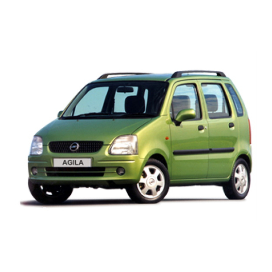
The Opel Agila is a city car produced since 2000. It is a rebadged version of the first generation of the Suzuki Wagon R+ and the second generation of the Suzuki Splash. Opel Agila?s first generation was categorized as a city car, while its second variant is a mini MPV. All of Agila?s engines contain the Ecotec technology. It has been marketed under the Vauxhall marque in the United Kingdom.The Agila was built at Opel’s factory in Gliwice, Poland.
How do I
How do I adjust the headlights in my Opel Agila?
To adjust the headlights in your Opel Agila, park the vehicle on a level surface facing a wall or garage door. Measure the distance between the ground and the center of each headlight. Mark the wall or door at the same height as the measurements. Turn on the headlights and observe the light patterns on the wall or door. Use the adjustment screws located near the headlight assembly to align the light patterns with the marked heights. It is recommended to consult the Opel Agila automotive repair manual for the specific adjustment procedures and measurements.
How do I change the air filter in my Opel Agila?
To change the air filter in your Opel Agila, locate the air filter housing, which is usually on top of the engine. Open the housing by removing the clips or screws that hold it in place. Take out the old air filter and replace it with a new one, making sure it is properly seated. Close the housing and secure it with the clips or screws. Regularly replacing the air filter helps maintain the efficiency and performance of your Opel Agila’s engine.
How do I change the oil in my Opel Agila?
To change the oil in your Opel Agila, begin by locating the oil drain plug underneath the vehicle. Use a wrench to loosen and remove the plug, allowing the old oil to drain into a suitable container. Once the oil has completely drained, replace the drain plug and proceed to remove the oil filter, replacing it with a new one. Finally, refill the engine with the recommended amount and type of oil specified in the Opel Agila automotive repair manual.
How do I change the windshield wiper blades on my Opel Agila?
To change the windshield wiper blades on your Opel Agila, lift the wiper arm away from the windshield until it locks into an upright position. Locate the small tab or release button near the wiper blade attachment point and press it to release the old blade. Remove the old blade by pulling it downward or away from the wiper arm. Attach the new wiper blade by sliding it onto the wiper arm until it clicks into place. Gently lower the wiper arm back onto the windshield. Repeat the process for the other wiper blade. It is recommended to consult the Opel Agila automotive repair manual for any specific instructions or variations.
How do I check the tire pressure in my Opel Agila?
To check the tire pressure in your Opel Agila, start by locating the valve stem on each tire. Remove the valve cap and press a tire pressure gauge onto the valve stem until you hear a hissing sound. Read the pressure indicated on the gauge and compare it to the recommended tire pressure specified in the Opel Agila automotive repair manual. If the pressure is too low, add air using a compressor or at a gas station. If the pressure is too high, release some air by pressing the center pin in the valve stem.
How do I replace a blown fuse in my Opel Agila?
To replace a blown fuse in your Opel Agila, locate the fuse box, which is usually found in the engine compartment or on the side of the dashboard. Open the fuse box and find the fuse that corresponds to the malfunctioning component. Use a fuse puller or a pair of needle-nose pliers to remove the blown fuse and replace it with a new one of the same amperage rating. Refer to the Opel Agila automotive repair manual for the exact location and amperage rating of each fuse.
How do I replace a broken side mirror in my Opel Agila?
To replace a broken side mirror in your Opel Agila, start by removing the interior door panel to access the mirror assembly. Disconnect the electrical connector for the mirror, then remove the mounting bolts or screws that secure the mirror to the door. Carefully remove the broken mirror and replace it with a new one, ensuring it is properly aligned. Reattach the mounting bolts or screws, reconnect the electrical connector, and reinstall the interior door panel. Consult the Opel Agila automotive repair manual for detailed instructions and illustrations specific to your vehicle’s model and year.
How do I replace a faulty brake light bulb in my Opel Agila?
To replace a faulty brake light bulb in your Opel Agila, open the trunk or rear hatch and locate the back of the brake light assembly. Remove the screws or clips that hold the assembly in place. Carefully pull the assembly away from the vehicle, exposing the bulb sockets. Twist the socket counterclockwise to remove it from the assembly, then remove the old bulb and replace it with a new one. Reverse the steps to reassemble the brake light assembly and test the brake lights to ensure they are functioning properly.
How do I replace a headlight bulb in my Opel Agila?
To replace a headlight bulb in your Opel Agila, open the hood and locate the back of the headlight assembly. Unplug the electrical connector from the bulb, then remove the retaining clip or ring that holds the bulb in place. Carefully remove the old bulb and replace it with a new one, making sure not to touch the glass portion of the bulb. Reattach the retaining clip or ring, plug in the electrical connector, and test the headlight to ensure it is working properly.
How do I reset the maintenance light in my Opel Agila?
To reset the maintenance light in your Opel Agila, turn the ignition switch to the «ON» position without starting the engine. Within three seconds, fully press and release the accelerator pedal three times. The maintenance light should start flashing, indicating that the reset procedure has been initiated. Once the light stops flashing and remains off, the maintenance light has been successfully reset. Refer to the Opel Agila automotive repair manual for any additional steps or variations in the reset procedure.
How do I troubleshoot a malfunctioning power window in my Opel Agila?
If you are experiencing issues with a malfunctioning power window in your Opel Agila, start by checking the fuse associated with the power window circuit. If the fuse is intact, you may need to inspect the window switch for any signs of damage or wear. Test the switch using a multimeter to determine if it is functioning properly. If the switch is working, you may need to check the wiring and connections for any faults. It is recommended to refer to the Opel Agila automotive repair manual for a detailed troubleshooting guide specific to your vehicle’s model and year.
How often should I replace the spark plugs in my Opel Agila?
The recommended interval for spark plug replacement in your Opel Agila is typically every 30,000 to 50,000 miles or as specified in the Opel Agila automotive repair manual. However, it is important to consider factors such as driving conditions, fuel quality, and overall engine performance. If you notice symptoms like rough idling, decreased fuel efficiency, or difficulty starting the engine, it may be a sign that your spark plugs need replacement. Consult the Opel Agila automotive repair manual for the specific spark plug type and replacement procedure.
What should I do if my Opel Agila’s battery is dead?
If your Opel Agila’s battery is dead, start by ensuring that all electrical accessories are turned off. Then, connect jumper cables to a functioning vehicle’s battery and the dead battery of your Opel Agila. Allow the functioning vehicle to run for a few minutes, then attempt to start your Opel Agila. If it starts, let it run for a while to recharge the battery. If it doesn’t start, you may need to replace the battery or seek professional assistance.
What should I do if my Opel Agila’s engine overheats?
If your Opel Agila’s engine overheats, safely pull over to the side of the road and turn off the engine. Allow the engine to cool down completely before attempting to check the coolant level. Once cooled, check the coolant reservoir and add coolant if necessary. If the coolant level is fine, there may be an issue with the cooling system, such as a malfunctioning radiator or water pump. In such cases, it is recommended to consult the Opel Agila automotive repair manual or seek professional assistance.
- Manuals
- Brands
- Opel Manuals
- Automobile
- Agila
- Manual
-
Contents
-
Table of Contents
-
Bookmarks
Quick Links
Aftersales Training
Participant’s Handout
Opel Agila
LAAS07
V 1.0
Click here to go back to the Leadersguide
Related Manuals for Opel Agila
Summary of Contents for Opel Agila
-
Page 1
Aftersales Training Participant’s Handout Opel Agila LAAS07 V 1.0 Click here to go back to the Leadersguide… -
Page 3: Table Of Contents
Page 1……General introduction of the Opel Agila _______ 4 2……..Body and Safety features ______ 13 3.
-
Page 4: General Introduction Of The Opel Agila
1. General introduction of the Opel Agila Introduction For the model year 2000½, Opel introduces the new Agila, a car that belongs to the so-called Mini People Carrier segment. With this vehicle Opel is the first European car The Agila is a Sub-S model, which…
-
Page 5
— Electrically adjustable mirrors — Electronic power steering — Air conditioning (optional) — Power windows (optional) Performance: The Agila is available with two different engines: — 1.0 litre 12V engine (Z10XE) with 58 Hp — 1.2 litre 16V engine (Z12XE) with… -
Page 6
Some engine features: The Z- emission stands for the internal definition of the compliance — Double oxygen sensor to Euro IV emission regulations, that — Drive by wire (E-gas) will be effective by 2005. — Return-less fuel system — Catalytic converter welded to exhaust manifold — Plastic intake manifolds for both engines… -
Page 7
Dimensions of the Agila in mm The luggage compartment has a The Agila has a turning circle of 10.6 volume of 248 litres behind the m from wall to wall. second seat row. With the second… -
Page 8
European specifi- Z12XE 1340 Kg (1340 Kg with AC) cations and may vary from country to country. The maximum roof load for the Agila is 30 Kg. Agila Base: The fuel tank has a capacity of 41 — Electric power steering Litre. -
Page 9
J = Vectra V = Omega Model designation which indicates the version of the model: G for Astra-G, A for Agila-A, B for Corsa-B etc. GM code for body style 10 Model Year: W = 98, X = 99, Y =00 11 Manufacturing plant: 1= Rüsselsheim… -
Page 10
Thanks to its body shape, Agila offers a generous interior space. The Agila design provides maximum interior space vs. the small exterior size. The height of the Agila offers maximum headroom. Height adjustable headrests on the front seats are standard. The rear… -
Page 11
On the rear window a centre high Exterior mounted stop light is installed. The Agila has the following features The size of the tyres of the Agila is related to the exterior. 155/65 R14. Currently only pro- duced by the manufacturers Kleber The Agila front design is character- and Michelin. -
Page 12
• Central armrest • Towing hitch • Fog lights • Opel FIX child seat • Boot storage box • Low profile base carrier • Opel i-line interior and exterior accessories • Sunroof Opel i-line exterior spoiler Sport Interior… -
Page 13: Body And Safety Features
2. Body and Safety features Body equipment 2.1.1 Bonnet The bonnet is connected to the body with two scissor-type hinges. With these two scissor-type hinges it is possible to adjust the bonnet perfectly to the body work. 2.1.2 Wings To remove the front wings, the front bumper and wheel arches must be removed from the body.
-
Page 14
2.1.3 Front/rear doors To increase the passive safety level of the Agila the doors are equipped with side impact door bars. It is not allowed to adjust or replace these door bars. The hinges are welded to to the body. -
Page 15
2.1.5 Bumpers After every disassembly of the front or rear bar new self-locking nuts To reduce repair costs in the event must be used. of a collision the front and rear members are connected with nuts to the chassis, when the front or rear member is removed, parts mounted behind the bars are easy accessible. -
Page 16
2.1.6 Side windows The Agila will be available with manual operated windows and optional with electrically operated windows. Electrically operated windows are only available on the front doors. The manual operated windows of the front and rear doors are similar. -
Page 17
For the Agila is a sunroof available as an option. This sunroof is similar to the sunroof available for the Astra-G. The body mouldings on the Agila are glued and can be removed by heating them with a hairdryer. -
Page 18
2.1.9 Roof railing Safety Features On the standard equipped Agila a 2.2.1 Freewheeling lock cylin- roof railing is only available as an ders option. With all other model variants the roof railing is standard. The roof The front doors and the trunk lid are… -
Page 19
Two for the front airbags principal of the seatbelt pretensioner and two for the seatbelt The known seatbelt pretensioners of the Agila is similar to the known pretensioners. from Opel are all located at the lock seatbelt pretensioners. So there is The control unit is serviceable with of the safety belt. -
Page 20
The energy of the pyrotechnical load is not brought to the retractor by a cable like all other seatbelt pre- tensioners Opel uses. The manufac- turer (Autoliv) of this seatbelt pretensioner invented a new way for this energy transmission. -
Page 21
And now you’re able to secure a child seat tightly to the rearseat. The load limiter on the pretensioners af the Agila is created by a torsion The pedal release system is bar in the retractor. When the standard for the clutch and the safety belt reaches a certain force brake pedal on the Agila. -
Page 23: Heating, Ventilation And Air-Conditioning
3. Heating, ventilation and air-conditioning The Opel Agila is standard equipped The following features can be Heating and ventilation with a conventional heating and identified: features ventilation system. On both engine versions air conditioning is optionally • A four speed fan is used.
-
Page 24
Dash panel air vent holes rear passengers are not avail- The heating and ventilation system able. The outer dashboard vents of the Opel Agila has 10 outlets. The have adjustable doors. The distrbution of the air is controlled Centre outlets have no doors. -
Page 25
1. Heater core 2. Temperature control flap 3. Feet outlets 4. Feet outlet control flap 5. Center outlet control flap 6. Center outlets 7. Defrost outlets 8. Blower 9. Resistor pack… -
Page 26
The following illustrations show the air flow through the heater housing, depending on the air distribution control knob position. -
Page 30
These channels have separate doors, located in the outlets. The centre outlets do not have these doors as with other Opel models. The recirculation flap is equipped with a small additional flap that… -
Page 31
1. Bulb The control panel bulbs are replace- able separately. The control panel must be removed to have proper access to the bulbs. The location of the bulbs is indicated in the illustra- tion above. G0792 1. Body vents The required body vents are located on the rear end of the car, behind the impact limiter (bumper) and on the inside of the rear doorsill panel… -
Page 32
G0793 1. Body vents The additional small flap in the recirculation flap also adds to the decompression during the closing of the doors and the tailgate. The vents contribute to a better airflow in the interior and therefor help to demist the windows. -
Page 33
Air conditioning features The air conditioning system of the Opel Agila is an add-on unit. The system has a new design, accord- ing to the Opel standards. The system is designed for the use of R134A refrigerant only. The air… -
Page 34
The compressor, condenser, Engine compartment receiver / dryer and the ECU are located in the engine compartment 1. Low pressure service port at the usual locations. The com- 2. Pipe connection pressor is the same as the one 3. TXV used on the Corsa-B X10XE and 4. -
Page 35
A coolant cut-off valve is not used on the Opel Agila. This means that there are no additional switches in the control panel. Underneath the evaporator are the water collector and the water drain. -
Page 36
The receiver / dryer can be replaced separately. The linear refrigerant pressure sensor is positioned in the high-pressure liquid line from the condenser to the TXV, close to the longitudinal front member. The sensor is similar to the used on from the Opel Astra-G. -
Page 37
Air conditioning operation An Engine Cooling Module (MKM) as used on the Opel Astra-G is not used on the Opel Agila. Instead, the engine control unit (ECU) controls the cooling fans and the compressor clutch via relays, based on the sensor inputs from the… -
Page 38
The illustration shows the electrical Component codes circuits for air conditioning and cooling fans. The following compo- •E15 Heated back window nents are shown: •K3 Relay — Heated back window Circuits •K13 Relay — Radiator fan •K36 Relay — Compressor, •Engine cooling 1102 — 1104 air conditioning… -
Page 39
Opel Agila. • When the air conditioning is switched ON the blower will run at first speed if it was not activated yet using relay K43. -
Page 41: Suspension
4. Suspension Front suspension General description The front suspension of the Opel Agila is designed using Mc Pherson type struts in combination with a stabiliser bar used as a trailing rod. The stabiliser bar has a constant diameter. The layout and tuning of…
-
Page 42
Service 1. Lower control arm mounting The lower control arm can only be 2. Lower control arm replaced as an assembly. No 3. Steering knuckle with wheel hub separate parts, such as bushings, can be ordered. In the illustration above the stabiliser bar is already removed. -
Page 43
K2062 1. Special wheel bolts 2. Hub 3. KM 6142 K2091 The hubs are equipped with four special bolts(1) to fix the rims, in combination with nuts. The normal tightening torque for the nuts is 85 Nm and dry nuts should be greased slightly. -
Page 44
Rear suspension General description The rear suspension of the Agila is a 1. Rear spring combination of a semi-independant 2. Panhard rod torsion type rear axle with a 3. Rear axle body with wheel hub Panhard rod. The journals form one 4. -
Page 45
Adjustments on the front and rear suspension The front suspension wheel align- ment values are listed in the table below: Wheel alignment Front Axle All versions Tolerance min. max. Camber -0° 20′ -1° 20′ 0° 40′ Toe-in -0° 10′ 0° 00′ -0°… -
Page 47: Brakes
5. Brakes The general features of the brake • A vacuum brake booster as system of the Opel Agila are: standard equipment. • Safety brace assembly for the • Diagonal split 4-channel brake Pedal Release System (PRS). system. • Optional ABS on all versions.
-
Page 48
Opel Astra-G. The inner brake pads are equipped with audible wear indicators. There are no electrical sensors used, because MID is not available on the Opel Agila. The anti-resonance springs are mounted on the brake pads. Calliper frame Calliper housing… -
Page 49
This is system that is alos used on other shown in the illustration below. Opel cars with drum brakes. The brake lining is glued to the brake shoes. Instead of coil springs a W- shaped retracting spring is used to return the brake shoes into the normal position. -
Page 50
(Corsa-B) a special nut is To remove of the brake fluid reser- Brake booster used on the Opel Agila. To secure voir special tool KM 6144 is neces- the nut the outer edge must be sary. With this tool the pin fixing the The brake booster is a vacuum-type bent into a recess in the spindle. -
Page 51
Maintenance and repairs Regarding brake maintenance and repairs, mentioned in the Service Plan and the Service Instructions, the Opel Agila should be treated similar to the other models in the Opel range. The following features ensure the safety of the drivers and the occupants. -
Page 52
The hydrau- lic modulator comes filled with brake fluid from Parts & Accessories (P&A). The standard bleeding procedure (mentioned in the Service Instruc- tions), as used on other Opel vehicles, can be used on the Agila too. -
Page 53
Electrical and electronic features The ABS of the Opel Agila incorpo- rates dynamic rear brake propor- tioning. The ABS versions are not equipped with a load sensing proportioning valve. When ABS is in emergency mode dynamic rear brake proportioning is not opera- tional. -
Page 54
A-pillar on the passenger side. This plug provides an additional blink code request for the ABS and EPS control units, by grounding the wires. Opel does not use the blink codes for diagnostic purposes, because there is a better diagnostic… -
Page 55: Engines
6. Engines Engine data Engine Types Z10XE The new New Opel Agila is available with two different engines: Output 43 kW/58 PS at 5600 rpm • The Z10XE a 1.0 litre 12V petrol Torque 85 Nm at 3800 rpm ECOTEC engine with 43 kW…
-
Page 56
Engine data Z12XE Output 55 kW/75 PS at 5600 rpm Torque 110 Nm at 4000 rpm Top speed 155 km/h Acceleration 0-100km/h 13.5 sec Fuel consumption (Lt/100 km) -Urban -Counry -Combined… -
Page 57
X10XE,X12XE Z10XE,Z12XE Engine management system Motronic M 1.5.5 Motronic ME 1.5.5 Number of oxygen sensors Fuel system X10XE X12XE Fuel supply and Returnless fuel sytem pressure regulator is return and line, component of the in-tank module pressure regulator on fuel line Intake manifold Aluminium Plastic… -
Page 58
Z12 XE compared with X10XE and X12XE On the new Z engines is the cata- lytic converter welded onto the ex- haust manifold. K3407 1. Heated oxygen sensor controls the mixture 2. Heatshield 3. Exhaust manifold with catalytic converter… -
Page 59
Oxygen sensors The new Z engines are ready for the EOBD regulations, these regulations require that the catalytic converter is controlled on its function. For this reason there are two heated oxygen sensors placed on the exhaust system of these Z engines. One is placed on top of the catalytic converter, this one controls the mixture. -
Page 60
Fuel system On both engines in the Agila is a return less fuel system used. This means that where normally two fuel lines (supply and return) were… -
Page 61
The in tank module is connected to Engine management system the engine management system with four wires, two for the fuel Both engines in the Agila are pump and two for the Fuel tank equipped with the Motronic ME content sensor. -
Page 62
Y engines. It potentiometer checks contains two potentiometers and no potentiometer 1. Both engines in the Agila are idle switch. The sensor pedal equipped with the Motronic ME position is connected to the engine 1.5.5 engine management system,… -
Page 63
During normal operation the signal The throttle body contains the different to the throttle bodies of the voltage of both potentiometers is throttle valve, the throttle positioner Y16XE and the Y22XE engine, never equal. The signal of (motor) and two potentiometers. these have an eight pin connector. -
Page 64
Where as, throttle potentiometer 2 shows a decrease in signal voltage when the throttle valve opens. The signal voltage range of this potentiometer is 5 to 0 Volts. The throttle positioner works in the When the accelerator is operated, same way as the one used on the the ECU receives a signal from the Y16XE and Y22XE. -
Page 65
The throttle valve is forced into this The opening and closing of the preset position by a spring. In this throttle valve is carried out by the preset position the throttle valve is throttle positioner that works in two partially open, allowing an engine directions. -
Page 66
PWM signals On further acceleration the throttle 900-1000 RPM valve reaches the preset position. The graphs of the throttle positioner The spring pressure becomes are made with use of the Tech 31. neutral. For the throttle valve to The ground probe is connected to open further, the throttle positioner pin 1 and the signal probe to pin must force the spring in the oppo-… -
Page 67
On acceleration the throttle valve 1100 — RPM position must be changed, the pulse On increased acceleration, the width will now change to achieve throttle valve opens further untill the this as additional force is required to engine reaches the demanded open the throttle valve. -
Page 68
Exhaust gas recirculation Fan control The Z10XE and Z12XE engines are To reduce the components the fan equipped with a modified linear is controlled by the ECU, this means exhaust gas recirculation valve (1). that the ECU sends a signal to a This electronically controlled compo- relay, which switches on the fan. -
Page 69
Emission control telltale (MIL) The emission control telltale informs the driver about malfunctions that lead to increased emissions or malfunctions that can damage the catalytic converter. This telltale is required by EOBD. -
Page 71: European On Board Diagnosis
OBD l. of 01-01-00. For Opel, OBD was introduced in For Opel the Agila and later on the 1985 on the C13LZ in the Corsa A. Speedster will have to comply with This system stores a DTC if an these regulations.
-
Page 72
OBD ll is required to monitor and perform diagnostic tests on vehicle emission systems. If the emissions were to rise above 1-1 ½ times the FTP (Federal test procedure) standards, then a malfunction indicator lamp (MIL) must be illuminated. The DTC’s were also standardised as of Model Year 1996. -
Page 73
EOBD and OBD ll (USA) are broadly EOBD similar in the areas of emission limits, diagnosed components and 7.3.1 European Union the list of defects with the potential to trigger the MIL. One of the measures taken by European Union (EU) to improve air Minor differences relative to the quality was a further reduction of OBD ll system are rooted in the… -
Page 74
7.3.2 EOBD & US OBD requirement comparison Typical Industry European OBD I OBD II Standard Manufacturer Dependent Standard codes Connector & Communica tion Protocols Misfire Cataytic converter Comprehen sive Component Monitor No response test response test No intrusive test intrusive test EVAP No leak… -
Page 75
7.3.3 The features of the EOBD Remark; the MIL will flash as long system. as the fault is present. More infor- mation about the circumstances is covered in a later stage. The regulations are compelled for Europe (newly sold cars) as of •… -
Page 76
EOBD uses an additional telltale for This telltale illuminates when a not emission-related defects, called defect arises which is emission the engine electronics telltale relevant. (formerly known as the Service Vehicle soon SVS lamp) Control lamp for engine electronics… -
Page 77
(city cycle, to be run 4x in a The test for Euro 4 is changed Step 1 7.4 Test cycle for EUR0 III row) compared to Euro 3 considering the period immediately after the start. • Effective running time: 195 For Euro 4 the period just after the 7.4.1 European Type approval seconds… -
Page 78
(Opel drive-cycle others are checked stances have passed. Therefore it is permanently. -
Page 79
1. Cold start, idle speed, approx. 3 3. Driving at constant speed Note: the test will be interrupted if; minutes: between 60 – 100 km/h, Checked function: Secondary approx. 15 minutes, In between • The engine speed exceeds air system. (If present) sufficient deceleration is de- 3000 rpm, tected. -
Page 80
7.5.2 Catalytic converter: moni 7.5 EOBD tests toring requirement 7.5.1 Tests of systems and According to the new EOBD components that are regulations, the catalytic converter’s exhaust emission rel efficiency must be monitored once a evant. drive cycle. This is done by using two oxygen EOBD tests the following systems;… -
Page 81
In case of an optimal functioning catalytic converter, the oxygen is fully consumed. Therefore the voltage of the second In case of deterioration of the oxygen sensor will be relatively catalytic converter the OSC will constant at a high level of approx. reduce and therefore the voltage of 0.7 V. -
Page 82
7.5.3 Misfire detection EOBD requirements. EOBD requires misfire detection under the following criteria: The phenomenon misfire detection is when an ignition (combustion) in a 1.Catalytic converter damaging certain cylinder does not take place, caused by either a fuel or ignition A level of misfire sufficient to result in system problem. -
Page 83
The ECU monitors the following The ECU maintains a record of a parameters: certain amount of crankshaft revolutions. • Crankshaft revolution speed If within this given record circum- • Engine speed stances as in 1 or 2 occur, a DTC •… -
Page 84
• No misfire detection on NOTE: rough road To detect misfire correctly, misfire will not be executed while vehicle is travelling on a rough road. The crankshaft sensor recognises rough road conditions. If a car is driving with snow- Note; 7.5.4 Fuel system chains, misfire detection will not be executed. -
Page 85
7.5.5 Fuel trim diagnostics 7.5.6 Heated Oxygen sensors (2HO2S) For maintaining the ideal air-fuel The air- fuel ratio is constantly kept ratio the ECU is capable to adapt within the optimal area. under all circumstances. This is done by measuring the For instance the altitude, humidity, composition of the exhaust gases. -
Page 86
1. Sensor Voltage test 2. Time to activity (warm-up time) 3. Response time To enable the oxygen sensor to This test is executed permanently The ‘Time to activity’ test, monitors measure the oxygen content, the under normal driving conditions. the sensor’s heater system by sensor needs to be heated. -
Page 87
7.5.7 Evaporative Emissions 7.5.8 Fuel level System The tank level sensor measures the The EVAP system is used to collect fuel level of the tank. fuel vapour from the fuel tank. This information is used for misfire These vapours are stored in a detection. -
Page 88
7.6 DTC memories and types 7.6.1 Diagnostic scan tool The Diagnostic Trouble Codes At this moment three different (DTC’s) are transmitted from the protocols for transmitting data are engine control unit to the generic used. scan tool in digital form by way of standardised data transmission Form of data protocols in CARB and formats. -
Page 89
7.6.2 Diagnostic Trouble Codes (DTC) The Society of Automotive Engi- neers (SAE) compelled the diagnos- tic trouble codes for the OBD II systems (USA). For EOBD, the DTC’s were adopted accordingly after being internationally standard- ised. The DTC’s can be identified by means of their alphanumeric structure. -
Page 90
• detection will occur, this fault shall Normal Fault be stored finally up to the end of a Under a normal fault, Opel under- later trip. stands the detection of a clear To read out DTC’s which are detectable electronic problem, open… -
Page 91
• Limp home failures 7.6.4 DTC Freeze Frame I f one of the emission systems The Diagnostic Executive in the comes into a limp home or back up ECU records certain vehicle operat- mode, a DTC will be stored, the ing conditions when an emission telltale engine electronics illuminates related Diagnostic Trouble Code is… -
Page 92
7.6.5 MIL/telltale engine electro- 7.6.6 Deletion of DTC nics illumination overview A DTC can be deleted if 40 failure- free warm-up cycles have passed, OBD I, critical (eg. Vehicle Speed) and the DTC was no longer de- OBD II, w/o Missfire (O2 esnsor’s) tected. -
Page 93
In case of an illuminated telltale, the mental minded. customer will have to consult the With the introduction of EOBD and Opel dealer. in some countries “EOBD tax The customer is advised to never reduction” the customer might carry out any repairs or adjustments… -
Page 94
Reducing the eingine load, will stop the flashing and the MIL will be steady ON. In both cases the driver will be advised to visit an Opel service station. Control lamp engine electronics… -
Page 95
Repeated turbine-geometric. illumination of the control light • Direct fuel injection, most informs the driver to visit an Opel important and viable one. service station. If it lights up briefly and goes out again this is of no significance. -
Page 97: Transmission And Clutch
2. Transmission description manual transmission. The forward 8. Drain plug gears are synchronised, the reverse 9. Oil collector All Opel Agila versions will be gear is not synchronised. The 10. Transmission housing cover equipped with a new transmission, transmission is operated using 11.
-
Page 98
Z10XE F12 — 4.39 4,39 Z12XE F12 — 4.11 4,11 The transmissions with clutch for the Z10XE and Z12XE versions are the same, except the final drive gears, the left hand bearing of the input shaft (1), the countershaft (2) and the shims. -
Page 99
As a result of the shorter engine Currently, the only repairs possible block of the Z10XE, and the fact on the F12 transmission are that the front right engine mounts of Replacement and adjustments of the Z10XE and the Z12XE are the bowden cable system. -
Page 100
8.1.2 Clutch The clutch pedal height and clutch pedal free play can be checked and 1. Lock nut adjusted on the Opel Agila. A spe- 2. Adjustment bolt cial procedure should be used to check and adjust these values. First the clutch pedal should be ad- justed to the same level as the brake pedal. -
Page 101: Steering
9. Steering Introduction The Agila has a conventional rack and pinion steering system. The Agila is standard equipped with Electric Power Steering (EPS). The steering system consists of the following components: 1. Airbag unit 2. Steering bolt 3. Steering wheel 4.
-
Page 102
An identification plate is located on The only difference in version is left- The steering ratio is 37.6 mm/ the steering gear; it contains the or right-hand drive; this can be revolution and the total steering ratio following information: identified by LH-EPS for left-hand is 17.6:1. -
Page 103
Electric Power Steering The new Opel Agila will be intro- duced with an Electric Power Steering system. The designation «Electric Power Steering» is abbrevi- ated as EPS, which appears on the control light on the instrument panel. Torque sensor EPS… -
Page 104
1. Steering column jacket Working principle EPS, 2. Steering spindle mechanical 3. Worm gear 4. Electric motor The Electric Power Steering system 5. EPS control unit mainly consists of two components, the steering shaft assembly and the electric motor assembly. A. -
Page 105
When the front wheels experience much resistance during turning the driver wants steering assistance. To detect wheel-turning resistance, the EPS system is equipped with a torque sensor. In case of wheel-turning resistance a certain torque in the steering shaft occurs. This torque causes the contact ring to move up- or down- wards, depending on the steering direction, because of the bearing… -
Page 106
The electric motor unit consists of an electric motor and an electric- magnetic clutch. The electric- magnetic clutch engages the electric motor with the worm gear when the engine is running and disengages as soon as the engine stops running. 1. -
Page 107
Terminal 5 of the EPS control unit Working principle EPS, leads to the telltale in the instru- electrical ment, at terminal 7 the vehicle speed signal enters the EPS control The circuit diagram of the EPS unit and at terminal 6 the engine system shows the following compo- revolution signal enters the EPS nents:… -
Page 108
The torque sensor, or deviation The electric motor is connected to sensor, only turns if the steering the EPS control unit via connector system experiences resistance. If X51 and contains 4 wires. Two thick the steering system experiences no wires (red and black) are used for resistance, the torque sensor is in the power supply to the electric its central position and 2.5 Volts will… -
Page 109
This PWM-signal can be positive, > The EPS system is fitted with 0 Volts, or negative, <0 Volts, overload protection. If the electric depending of the desired current motor current exceeds a limit for a flow through the electric motor specified period of time, the current turning the steering wheel clockwise is set back to a minimum value to… -
Page 111: Electrical Systems
10. Electrical systems 10.1 Introduction 10.2 Lighting, signalling and instrument The Agila which is the smallest car The Opel Agila has plastic headlight in the Opel range contains the lenses, which may not be cleaned following sophisticated electrical with abrasive or caustic agents. It is…
-
Page 112
Body front & Instrument panel connector • Y14 Headlamp levelling-Left • Y15 Headlamp levelling-Right The Agila has no single parking light feature but does contain a prepara- tion for additional fog lights in the wiring harness. The prepared fog lights connectors can be found behind the bumper close to the built-in location for fog lights. -
Page 113
The rear light units must be re- An instrument with tachometer is moved to replace the bulbs. optional for the Agila. The instru- ment of the Agila contains double trip odometer. 1. Electronic speedometer 2. Fuel indicator 3. Reset knob trip odometer 4. -
Page 114
• B0165 Coolant temperature signal low input. The instrument of the Agila is • B0166 Coolant temperature accessible for TECH 2. For the signal high input. following TECH 2 software features •… -
Page 115
10.3 Triple Info Display & Audio systems The optional Triple Info Display (TID) of the Agila is the same as used on the Astra-G with the exception of splice connector X23. This connec- tor is fixed on the wiring harness,… -
Page 116
The standard audio system of the Agila exists of the radio R2001 with two 7-Watt front speakers and 4 pre-settings. The R2001 has its own display and therefore it will not display informa- tion on the TID. All other optional radios will display information on the TID. -
Page 117
10.4 Power windows The front windows of the Agila can be equipped with power windows and are always combined with central door locking. Therefore the switch unit of power windows is combined with the lock/unlock button for the central door locking system. -
Page 118
• ZV Central door locking. • M8 Motor-window lifter, driver door. • M9 Motor-window lifter, front passenger door. • S17 Switch-window lifter. • S17.1 Switch-window lifter, driver door. • S17.2 Switch-window lifter, front passenger door. •` S17.6 Switch-central lock` ing. •… -
Page 119
10.5 Central door locking system With the help of the central door locking system of the Agila, it is possible to lock and unlock all doors simultaneously. The central door locking system, also called central locking, consists of the following… -
Page 120
The fuel filler cap can be locked via a separate lock operated The central door locking system of by the ignition key. the Agila has no overload protec- tion. Turning the key anti-clockwise once results in opening of that particular door only. -
Page 121
Central door locking • ASP Outside mirror • M54 Unit-Lock tailgate/lid • X7 Instrument panel & • FH Window lifters trunk Driver door • IRL Interior lamp • M54.1 Motor-Central locking • X8 Instrument panel & • TKS Door contact switch •… -
Page 122
When central locking is availabe,the motor (M54) on the hatch door (tailgate) has an internal switch for the lock/unlock switch (S102) is shared with the ground for power windows. The signal for lock, unlock and deadlock is the same, only the direction of current through the motor changes. -
Page 123
This sensor generates 25,714 Volts block signal to the instrument, pulses/km (±5%) with the standard the control unit for electronic power size tyres installed on the Agila. steering, the radio and the triple info display. Wheel speed sensor input signal at… -
Page 124
This module and/or the ABS gener- ate 8844 pulses/km. This value is also the K-factor of the instrument. This programming parameter can be displayed using the odometer display of the instrument. If the odometer-reset button is pressed for a period of 5 seconds or longer, the programming display appears. -
Page 125
Fuses & Relays In the circuit diagram 3 abbre- viations can be found for the fuses: Fc, Fb and Fl. The fuses indicated as Fc are located inside the vehicle. The abbreviation Fb indicates to mini fuses that are located in the engine compartment. -
Page 126
1. K45, Interval wiper, windscreen 2. K43, AC Blower 1 speed 3. U1, Speed signal converter module… -
Page 127
Ground points The following pictures indicate the 15 grounding points of a Left Hand Drive-Agila. 1. Engine compartment, left 4. Engine compartment, right 2. Engine compartment, left 5. Engine, left 3. Engine compartment, right 6. Flywheel housing… -
Page 128
7. Transmission housing 10. Bracket steering column/cross 13. D-pillar, right member 8. A-pillar, driver’s side 11. Chassis under seat, left 14. Tailgate, left 9. A-pillar, passenger’s side 12. Tunnel 15. Tailgate centre… -
Page 129: Service
• Changed adjustment of clutch pedal In the new version the emission • Parking brake is adjusted on the data of the Agila is added and these fourth tooth engine are tested according the • Air cleaner cartridge change on…
-
Page 130
11.7 Techline 11.8 Special Tools The following systems can be diag- 11.8.1 Body nosed with the TECH 2: KM-799-11 Adapter cable Motormanagement system: • Motronic ME 1.5.5 Hybrid For activation of airbag units and seatbelt pretensioners when fitted in the car. Body systems: •… -
Page 131
11.8.2 Front wheel suspension, KM-6142 wheel and tyres Fixing point Support wheel hub when pressed in or pressed out KM-6138 Fixing point Support of steering knuckle when wheel bearing is pressed in with KM-6139 KM-6139 Press tool for pressing wheel bearing in steering knuckel with KM-6138 KM-6140… -
Page 132
KM-6133 Installation tools Installation ABS sensor on hub of drum brake KM-6143 Adapter Removal ABS sensor of rear hub with KM-161-B KM-6144 Punch To remove spring pin brake fluid reservoir KM-6145 Reset tool To reset the adjusting mechanism of the drum brakes… -
Page 133
11.8.3 Engine KM-6054 For removal and installation of engine with KM-904 and KM-6056 KM-6056 Supports the engine with removal and installation with gearbox with KM-6054 KM-6103 Supports engine with installation and removal of cylinder head and for maintenance on ECM side. KM-6129 Installation an removal tool for Oxygen sensor with MKM-611… -
Page 134
11.8.4 Clutch and gearbox KM-6135 Centre pin for clutch plate KM-6133 Installation tool for sealing of crank shaft left with KM-523-1 KM-6134 Installation tool for sealing of crank- shaft right with KM-523-1…