- Manuals
- Brands
- Volvo Manuals
- Engine
- TAD1344GE
- Workshop manual
-
Contents
-
Table of Contents
-
Troubleshooting
-
Bookmarks
Quick Links
Workshop and repair manual
T
A
T
A
T
A
T
A
T
A
T
A
7748841
01/06/2010
V
O
L
V
O
V
O
L
V
O
E
n
g
i
n
e
E
n
g
i
n
e
D
1
3
4
3
D
1
3
4
3
D
1
3
4
4
D
1
3
4
4
D
1
3
4
5
D
1
3
4
5
G
E
G
E
G
E
G
E
G
E
G
E
33525078101_0_1
Related Manuals for Volvo TAD1344GE
Summary of Contents for Volvo TAD1344GE
-
Page 1
Workshop and repair manual 7748841 33525078101_0_1 01/06/2010… -
Page 3
Workshop Manual Group 00-08, 20-26, 32 5(0) TAD1341GE, TAD1342GE, TAD1343GE, TAD1344GE, TAD1345GE, TAD1340VE, TAD1341VE, TAD1342VE, TAD1343VE, TAD1344VE, TAD1345VE, TAD1350GE, TAD1351GE, TAD1352GE, TAD1353GE, TAD1354GE, TAD1355GE… -
Page 5: Table Of Contents
Content General Information 00-0 General ………………..2 00-9 Miscellaneous ………………6 Specifications 03-2 Specifications, Engine …………… 7 03-3 Specifications, Electrical …………..45 Safety and Other Instructions 05-1 Safety Instructions …………….48 Special tools 08-2 Special Service Tools …………… 52 General 20-0 Engine Information, General …………
-
Page 6: General Information
IMPORTANT! Neglected or poorly-performed care/service and the use of spare parts not approved by Volvo Penta, will mean that AB Volvo Penta no longer guarantees that the engine conforms to the certified model. Volvo Penta accepts no responsibility for damage or costs arising as a result of failure to follow the above mentioned standards.
-
Page 7: Repair Instructions
It is therefore critical that the stated wear toler- workshop. ances be adhered to, that systems which can be adjusted be correctly set up and that only Volvo Penta Warning symbols that occur in the service manual. Original Parts are used. The intervals in the care and For significance, refer to Safety Information .
-
Page 8
00-0 General Torque, angle tightening Sealing compounds etc. When torque/angle tightening, the fastener is tight- To ensure service work is correctly carried out it is ened to a specified torque, and tightening then con- important that the correct type of sealants and locking tinues through a pre-determined angle. -
Page 9
00-0 General The following seals are most probably made from flu- Safety regulations for fluorocarbon orocarbon rubber: rubber Seal rings for the crankshaft, camshaft, idler shafts. Fluorocarbon rubber is a common material in sealing rings for shafts, and in O-rings, for example. O-rings, regardless of where they are installed. -
Page 10: Miscellaneous
00-9 Miscellaneous 00-9 Miscellaneous IMPORTANT! The engine is equipped with a so-called visco-fan. When the fan is removed the viscous coupling must always stand upright. The coupling contains oil that will run out if it is laid on its side, and because the oil cannot run back in the fan will seize.
-
Page 11: Specifications, Engine
03-2 Specifications, Engine 03-2 Specifications, Engine General Tightening Torques General Tightening Torques M6 standard bolt 8.8 10 ± 1.5 Nm (7.4 ± 1.1 lbf ft) M8 standard bolt 8.8 24 ± 4 Nm (17.7 ± 2.95 lbf ft) M10 standard bolt 8.8 48 ±…
-
Page 12: Special Tightening Torques
03-2 Specifications, Engine Special Tightening Torques Group 21: Engine P0005219 Front engine mountings, engine block Stage 1: Tighten bolt (1) 85 ± 5 Nm (62.69 ± 3.69 lbf ft) Step 2: Tighten the bolts 2–4 105 ± 15 Nm (77.44 ± 11.06 lbf ft) Stage 3: Angle tighten the bolts 2–4 in sequence 60°…
-
Page 13
03-2 Specifications, Engine Frame reinforcement 24 22 19 18 14 11 23 21 16 13 12 9 P0005220 NOTICE! Tighten the bolts in sequence, as illustrated. The screws may not be reused. Frame reinforcement stage 1: Tighten the bolts 1–24 in sequence 45 ±… -
Page 14
03-2 Specifications, Engine Timing gear wheels P0005223 1 Drive gear, crankshaft 24 ± 4 Nm (17.7 ± 2.95 lbf ft) 2 Idler wheel, double gear outer: Stage 1 25 ± 3 Nm (18.44 ± 2.21 lbf ft) Stage 2 (angle tightening) 110°… -
Page 15
03-2 Specifications, Engine Flywheel and timing cover P0005224 P0005225 NOTICE! Run an approx. 2 mm (0.0787 in) silicone bead as illustrated above, max 20 min before installation. Flywheel housing Tighten all bolts in sequence to the following torque: M14 bolts 140 ±… -
Page 16
03-2 Specifications, Engine Timing Gear Cover, Upper P0005226 P0005290 P0005227 NOTICE! Run an approx. 2 mm (0.0787 in) silicone bead as in the illustrations, max 20 min before installation. Tighten the contact surfaces carefully. Install the cover in two stages: stage 1: Fasten the cover with bolts 1 and 2. -
Page 17
03-2 Specifications, Engine Flywheel P0005228 Flywheel stage 1: Tighten the bolts in sequence, as illustrated 60 ± 5 Nm (44.25 ± 3.69 lbf ft) stage 2: (angle tightening) 120° ± 10° NOTICE! Carefully check that the flange is clean and dry. Tighten the bolts in sequence, as illustrated. -
Page 18: Cylinder Head
03-2 Specifications, Engine Vibration damper, crankshaft P0005231 Vibration damper: stage 1: Tighten the bolts in sequence, as illustrated 35 ± 5 Nm (25.81 ± 3.69 lbf ft) stage 2: Tighten the bolts in sequence, as illustrated 90 ± 10 Nm (66.38 ± 7.38 lbf ft) NOTICE! The vibration damper 8.8 bolts may not be re-used.
-
Page 19
03-2 Specifications, Engine Bearing caps, camshaft/rocker arm shaft 15/9 16/10 17/11 18/12 19/13 14/8 15/9 16/10 17/11 18/12 19/13 14/8 15/9 16/10 17/11 18/12 19/13 14/8 15/9 16/10 17/11 18/12 19/13 14/8 15/9 16/10 17/11 18/12 19/13 14/8 15/9 16/10 17/11 18/12 19/13 14/8 15/9 16/10 17/11 18/12 19/13 15/9 16/10 17/11 18/12 19/13… -
Page 20
03-2 Specifications, Engine Valves / floating rocker arm / EGR P0005234 Locking nut (A), valve adjuster screw: (angle tightening) 60° ± 5° Bolt (B), floating rocker arm: (angle tightening) 30° + 15° / – 0° Locking nut (C), EGR rocker arm: (angle tightening) 45°… -
Page 21
03-2 Specifications, Engine Valve Cover p0005236 Valve Cover Tighten the bolts in sequence, as illustrated 24 ± 4 Nm (17.7 ± 2.95 lbf ft) 7748841 06-2010… -
Page 22
03-2 Specifications, Engine Group 22: Lubrication System Sump P0005237 Oil sump (material: plastic) Fasten the oil sump with bolts A and B and torque them 24 ± 4 Nm (17.7 ± 2.95 lbf ft) Tighten the bolts outwards from the center in the sequence 1–4 as illustrated above 24 ±… -
Page 23: Oil Cooler
03-2 Specifications, Engine Oil Cooler P0005238 NOTICE! Tighten the bolts diagonally and finish off by tight- ening the first bolts again. Oil Cooler, attachment bolts 27 ± 4 Nm (19.91 ± 2.95 lbf ft) p0005239 Oil cooler cover Install the cover on the engine block and fasten bolt A in the oval hole.
-
Page 24
03-2 Specifications, Engine p0005240 Oil filter housing Thermostat valve or pressure valve, oil cooler, bolt (1) M6 standard bolt torque Safety valve, oil pressure, plug (2) 50 ± 5 Nm (36.88 ± 3.69 lbf ft) Overflow valve, oil filter, plug (3) 55 ±… -
Page 25
03-2 Specifications, Engine Group 23: Fuel System Unit injector p0005241 Yoke, unit injector (when replacing copper sleeve) First tightening: stage 1 20 + 5 / – 0 Nm (14.75 + 3.69 / – 0 lbf ft) stage 2 (angle tightening) 180°… -
Page 26
03-2 Specifications, Engine P0012337 Bolts (1) for adapter incl. fuel pump 24 ± 2 Nm (17.7 ± 1.48 lbf ft) P0012338 Bolts (1) for fuel pump (installed on adapter) 8 + 2 / – 0 Nm (5.90 + 1.48 / – 0 lbf ft) 7748841 06-2010… -
Page 27
03-2 Specifications, Engine Bypass valve / fuel line brackets p0005243 Fuel line brackets, tightening torques: 18 ± 3 Nm (13.28 ± 2.21 lbf ft) 24 ± 4 Nm (17.7 ± 2.95 lbf ft) (B) Brackets [standard tightening torque] 30 ± 4 Nm (22.13 ± 2.95 lbf ft) 35 ±… -
Page 28: Exhaust Manifold
03-2 Specifications, Engine Group 25: Inlet and Exhaust System Inlet Manifold P0006696 Inlet Manifold Torque the bolts 24 ± 4 Nm (17.7 ± 2.95 lbf ft) M10 plug, inlet manifold 20 ± 3 Nm (14.75 ± 2.21 lbf ft) Exhaust Manifold P0005246 Exhaust Manifold Stage 1:…
-
Page 29: Location Of Sensors
03-2 Specifications, Engine Location of Sensors P0004318 1 Auxiliary stop 2 Charge pressure sensor / Charge air temperature sensor M6 standard bolt torque 3 Oil pressure sensor 30 ± 5 Nm 4 Crankcase sensor 30 ± 5 Nm 5 Water separator level sensor not replaceable, integrated in lines 6 Oil level and oil temperature sensor standard bolt torque…
-
Page 30: Engine, General
The essential information is always correct, however. TAD1341GE, TAD1343GE, TAD1343GE, TAD1344GE, TAD1345GE, TAD1340VE, TAD1341VE, TAD1342VE, TAD1343VE, TAD1344VE, TAD1345VE, TAD1350GE, TAD1351GE, TAD1352GE, TAD1353GE, Type designation TAD1354GE, TAD1355GE No.
-
Page 31: Technical Data
03-2 Specifications, Engine Engine Technical Data Engine body Cylinder Head Max unevenness (bottom surface) 0.1 mm (0.00394 in) Cylinder Head Bolts No./cylinder head Thread dimension Length 200 mm (7.87 in) Cylinder block Length 1052 mm (41.41 in) Height, upper block plane-crankshaft center 422 mm (16.61 in) Height, lower block plane-crankshaft center 120 mm (4.72 in)
-
Page 32: Piston Rings
03-2 Specifications, Engine Piston rings p0005201 Compression Rings Quantity Marking Up (color marking to left of gap) Piston ring clearance in groove: upper compression ring (trapezoid profile) lower compression ring 0.09–0.14 mm (0.00354–0.00551 in) Piston ring gap, measured at ring opening: upper compression ring 0.40–0.55 mm (0.0157–0.0217 in) Wear tolerance <…
-
Page 33: Valve Mechanism
03-2 Specifications, Engine Valve mechanism Valves p0005201 Valve head, diameter: Inlet 42 mm (1.654 in) Exhaust 40 mm (1.575 in) Valve stem, diameter: Inlet / exhaust 8 mm (0.315 in) Valve seat angle (A): Inlet 24,5° ± 0,2° Exhaust 39,5° Seat angle in cylinder head (B): Inlet 25°…
-
Page 34
03-2 Specifications, Engine Valve clearance, cold engine, setting value: Inlet 0.2 mm (0.00787 in) Exhaust 0.8 mm (0.0315 in) Exhaust, EGR Counter clockwise adjustment, 1 ¾ turns, (630°) Rocker arm, EGR TAD1350GE, TAD1351GE, TAD1352GE, TAD1353GE, TAD1354GE, TAD1355GE Rocker arm, EGR, adjustment: Allow the feeler gauge to remain in place after adjust- ing the valve clearance and adjust the EGR rocker arm by loosening the locking nut and adjusting the screw… -
Page 35: Valve Seats
03-2 Specifications, Engine P0005197 Rocker arm, EGR, check value 3.8 ± 0.1 mm (0.15 ± 0.00394 in) Valve seats p0005205 Outer diameter (A): Standard Oversize dimen- sion Inlet 45.1 mm (1.7756 in) 45.3 mm (1.7835 in) 43.1 mm Exhaust (1.6968 in) 43.3 mm (1.7047 in) Height (B): Inlet…
-
Page 36: Valve Guides
03-2 Specifications, Engine Valve seat position p0005206 Diameter (C): Standard Oversize dimen- sion Inlet 45.2 (1.7795 in) [0/+0.025 mm] 45.0 mm (1.772 in) (0/+0.000984 in) 43.2 (1.7008 in) Exhaust [0/+0.025 mm] 43.0 mm (1.693 in) (0/+0.000984 in) Depth (D): Inlet 11.8 ±…
-
Page 37: Valve Springs
03-2 Specifications, Engine Rocker Arm p0005208 Wear values Bearing play (1) max 0.1 mm (0.00394 in) Roller cam follower, clearance (2) max 0.1 mm (0.00394 in) Valve springs Inlet Length uncompressed 73.8 mm (2.9055 in) Exhaust Length uncompressed 73.8 mm (2.9055 in) 7748841 06-2010…
-
Page 38
03-2 Specifications, Engine Engine Transmission Timing gear wheels 1 Drive gear, crankshaft 2 Intermediate gear: outer gearwheel, inner gear- wheel 3 Intermediate gear (adjustable) 4 Drive gear, camshaft 5 Intermediate gear 6 Drive gear, power steering pump and fuel feed pump 7 Drive gear, lubrication oil pump p0005209… -
Page 39
03-2 Specifications, Engine Camshaft Camshaft drive gearwheel No. of bearings Diameter, bearing journals, standard 69.97–70.00 mm (2.755–2.756 in) Diameter, bearing journals, undersize: 0.25 mm (0.00984 in) 69.72–69.78 mm (2.745–2.747 in) 0.50 mm (0.0197 in) 69.47–69.53 mm (2.735–2.737″) 0.75 mm (0.0295 in) 69.22–69.28 mm (2.725–2.728 in) Permissible wear, entire camshaft profile max 0.1 mm (0.00394 in) -
Page 40: Crank Mechanism
03-2 Specifications, Engine Crank Mechanism Crankshaft Wear value Crankshaft end float max 0.4 mm (0.01575 in) Machining value Ovality of main bearing journals and connecting rod journal max 0.006 mm (0.0002362 in) Center main bearing runout max 0.15 mm (0.00591 in) 1) Dimensions refer to greased components.
-
Page 41
03-2 Specifications, Engine Thrust washers (thrust bearing) p0005210 Width (B) standard 3.18 mm (0.1252 in) Oversize dimension: 0.1 mm (0.00394 in) 3.28 mm (0.1291 in) 0.2 mm (0.00787 in) 3.38 mm (0.1331 in) 0.3 mm (0.0118 in) 3.48 mm (0.1370 in) Main bearing cup Thickness (D) standard 2.48 mm (0.0976 in) -
Page 42
03-2 Specifications, Engine Big-end journals p0005211 Diameter (Ø) 99.0 mm (3.898 in) Undersize dimension: 0.25 mm (0.00984 in) 98.75 mm (3.8878 in) 0.50 mm (0.0197 in) 98.50 mm (3.8779 in) 0.75 mm (0.0295 in) 98.25 mm (3.8681 in) 1.00 mm (0.0394 in) 98.00 mm (3.8583 in) 1.25 mm (0.0492 in) 97.75 mm (3.8484 in) -
Page 43: Connecting Rod
03-2 Specifications, Engine Connecting rod Marking: ”FRONT” on the connecting rod faces forward. The connecting rod and bearing caps are marked in pairs with a three-digit serial number (see illustration). p0005212 Wear value End float, connecting rod–crankshaft max 0.35 mm (0.01378 in) Connecting rod bearing, radial clearance max 0.1 mm (0.00394 in) 1) Dimensions refer to greased components.
-
Page 44: Lubrication System
03-2 Specifications, Engine Lubrication System Technical Data Oil change volume 36 liter 9.51 US gals Oil volume between min and max markings 11 liter 2.91 US gals Oil Pressure Operating speed (above 1100 rpm) 300–550 kPa 43.5–79.8 psi Cold engine (above 1100 rpm) –650 kPa –94.3 psi Low idle (min)
-
Page 45: Oil Filter
03-2 Specifications, Engine Oil Filter Number Full flow filter Bypass filter Oil valves 1 Thermostat valve, oil cooler Opening temperature 105–107 °C (221–224.6 °F) 2 Safety valve, block Marking Yellow 3 Bypass valve, full flow filter Spring, free length 69 mm (2.717 in) Compressed 13–15 N (2.9–3.4 lbf) 40 mm (1.575 in)
-
Page 46: Feed Pump
03-2 Specifications, Engine Fuel System Technical Data NOTICE! For the below-mentioned values, fuel is required to fulfill the requirements specified in 03-0, Fuel and Oils. Feed pump Feed pressure at: 600 rpm 100 kPa 14.5 PSI 1200 rpm 300 kPa 43.5 PSI full load 300 kPa…
-
Page 47
03-2 Specifications, Engine Inlet and Exhaust System Technical Data Pressure drop indicator The pressure drop indicator control lamp lights up at a pres- sure drop relative to ambient air pressure of: 50 ± 5 kPa 7.25 ± 0.7 PSI 7748841 06-2010… -
Page 48
Mix with Water (According to ASTM D4985) Mixing proportions (conc. coolant/water) 40/60 NOTICE! Do not use Volvo Coolant VCS (yellow in color) in Volvo Penta engines. NOTICE! Do not mix different kinds of coolant. Refill quantity Coolant quantity (engine, radiator and hoses): TAD1340–53 GE/VE… -
Page 49: Specifications, Electrical
03-3 Specifications, Electrical 03-3 Specifications, Electrical Steering System Sensor Engine oil temperature sensor Tempera- Impe- Impedance Impe- ture dance dance (°C) (°F) (Ω) (Ω) (Ω) 73796 –50 –58 89496,5 105290,0 121083,5 –40 –40 45163,6 52394,0 59624,4 52394 –30 –22 23871,0 27375,0 30879,0 –20…
-
Page 50
03-3 Specifications, Electrical Coolant temperature sensor Tempera- Impe- Impedance Impe- Ω ture dance dance 45313 (°C) (°F) (Ω) (Ω) (Ω) –40 –40 40490 45313 50136 –30 –22 23580 26114 28647 –20 –4 14096 15462 16827 26114 –10 8642 9377 10152 5466 5896 6326… -
Page 51: Camshaft Sensor
03-3 Specifications, Electrical Pressure drop indicator Active V = 0.48 × U ± 10 % V = 0.12 × U ± 10 % Inactive Camshaft sensor Distance to gearwheel 1.1 ± 0.4 mm (0.0433 ± 0.01575 in) Crankcase sensor Sensor alarm limit 5 kPa (0.725 PSI) Crankcase pressure, normal value <…
-
Page 52: Safety Instructions
This Service Manual contains repair instructions, descriptions and technical data for products or product designs from Volvo Penta. Ensure that you are using the correct service manual. Read the safety information below and the service manual section About this Workshop manual and Repair instructions carefully before repair and service work is begun.
-
Page 53
05-1 Safety Instructions Immobilize the engine by turning off the power Avoid opening the coolant filling cap when the supply to the engine at the main switch engine is hot. Steam or hot coolant can spray (switches) and lock it (them) in the off position out and system pressure will be lost. -
Page 54
05-1 Safety Instructions Always use protective glasses or goggles when Never start the engine with the valve cover carrying out work where a risk of splinters, removed. There is a risk of personal injury. grinding sparks, splashes from acid or other chemicals is present. -
Page 55
05-1 Safety Instructions The components in the electrical and fuel sys- Exercise extreme caution when leak-detecting tems on Volvo Penta products are designed and on the fuel system and testing the fuel injector manufactured to minimize the risk of fire and nozzles. -
Page 56: Special Tools
08-2 Special Service Tools 08-2 Special Service Tools The following special tools are used when working on the engine. The tools can be ordered from AB Volvo Penta by specifying the number indicated. P0001857 P0002947 9996398 Manometer 1678297 Spacer 9991801 Standard handle Adjusting e.g.
-
Page 57
08-2 Special Service Tools p0004330 9996049 Draining hose 9996394 Support 9996395 Support Cooling system, draining. Support leg for 9996645 Puller. Support leg for 9996645 Puller. P0004332 9986179 Puller 9996400 Slide hammer 9996645 Puller Flywheel bearing For use with cylinder liners. p0006803 9996666 Nipple 9998007 Adapter… -
Page 58
08-2 Special Service Tools P0001878 9986173 Puller 9998599 Cleaning kit 9999179 Extractor oil filter Flywheel bearing Removal of filters. The tool kit includes: 9808570 Brush 9808616 Extender 9998580 Protective sleeve. P0002793 9998487 Sleeve 88800021 Drift 88800083 Piston ring pliers Removal of filters. Removal of crankshaft seal. -
Page 59
08-2 Special Service Tools P0001872 p0006800 P0004276 88800151 Drift 3849613 Pressure testing kit 9996441 Cover, with connect- ing nipple Valve stem seals. Pressure testing cooling system. Pressure testing cooling system. P0010357 P0010358 9996662 Pressure testing kit 88800117 Plate 9998674 Adapter Pressure testing cooling system. -
Page 60
08-2 Special Service Tools p0006797 p0006802 P0007585 88800003 Fixture 885519 Guide pin 9996239 Lifting tool For use with 88800117 Plate. Aligning inlet manifold. 2 pcs. required. P00068115 P0006813 9998264 Lifting tool 885810 Fixture 9998601 Fixture Lifting the camshaft. Installation of upper timing Installation of upper timing cover. -
Page 61
08-2 Special Service Tools P0006790 P0006794 p0006796 88800127 Drift 88800147 Drift 9992670 Hand pump Valve guides. Valve guides. Alternative to 9809726 Pneu- matic hydraulic pump . P0006776 P0006795 p0006801 9990160 Fixture 9990174 Drift 9998246 Drift Cylinder head. Valve springs. Valve springs. P0006780 P0006778 P0006791… -
Page 62: Other Equipment
08-2 Special Service Tools Other Equipment The following miscellaneous equipment is used when working on the engine. The equipment can be ordered from AB Volvo Penta by specifying the number indi- cated. P0004344 P0002936 P0002930 885510 Plugs 885633 Torque multiplier 1159794 Torque wrench For use with e.g.
-
Page 63: Engine Information, General
20-0 Engine Information, General 20-0 Engine Information, General Design and Function Identification Numbers P0002050 A Chassis number B Serial number P0002051 A Engine designation B Engine power, net, (without fan) C Max. engine speed D Main software E Dataset 1 F Data set 2 P0002052 G Product number…
-
Page 64
20-0 Engine Information, General Group 21: Engine General The engine is an inline six cylinder direct injection tur- bocharged diesel with charge air cooling and EMS (Engine Management System). The timing is at the rear. The engine is equipped with a one-piece cylinder head, overhead camshaft and unit injectors. -
Page 65
20-0 Engine Information, General Cylinder Head P0006000 The cylinder head is made from a single piece of cast The fuel channel to the unit injectors is drilled length- iron, which provides for stable overhead camshaft wise through the cylinder head and has a machined, bearings. -
Page 66
20-0 Engine Information, General P0006001 There are two guide pins on the right side of the cyl- inder head that ensure the valve cover is fitted in the correct position. 7748841 06-2010… -
Page 67
20-0 Engine Information, General P0006002 The injectors are centrally located between the four the camshaft to the valve pair. The valves have three valves and are held in place by yokes (A). For maxi- grooves and matching collets (D). The design of the mum cooling the coolant chamber in the cylinder head collets allows the valves to rotate on their seats. -
Page 68
20-0 Engine Information, General P0006003 There is a copper sleeve between the lower injector The copper sleeve is enlarged in the lower section section and the cylinder head. The copper sleeve is and sealed with a O-ring at the upper section. of a new, harder type;… -
Page 69
20-0 Engine Information, General Cylinder block P0006005 The cylinder block is made of cast iron and is cast in one piece. There are two, drilled, longitudinal ducts for the lubri- cation system. On the left side of the block there is the main lubrication duct (gallery), and on the right side there is a piston cooling duct. -
Page 70
20-0 Engine Information, General P0006006 The bowed shape of the block sides at each cylinder provides the cylinder block with high torsional stiff- ness and sound dampening. The vertical cross section shows the position of the cylinder liner and cooling jacket in the block. In order to render impossible the faulty positioning of main bearing caps, they are guided into position by cast, asymmetrically-located tabs (1) into correspond-… -
Page 71
20-0 Engine Information, General Engine stiffening frame and oil sump P0006007 In order to reduce vibrations in the cylinder block, and thus reduce engine noise, there is a stiffening frame (1) installed on the underside of the block. The stiff- ening frame is made from 6 mm sheet steel and is bolted in place to the lower block plane (A). -
Page 72
20-0 Engine Information, General Sealing joints The engine has wet cylinder liners for effective heat removal. They are sealed against the cylinder block by rubber rings. The uppermost ring is located imme- diately below the liner collar (A). The liner sealing sur- face against the cylinder head gasket is convex. -
Page 73
20-0 Engine Information, General Cylinder head, guides to cylinder block P0006009 In order to facilitate installation and exact positioning of the cylinder head on the cylinder block, there are three guide washers on the left side of the engine – two on the cylinder block (1) and one on the cylinder head (2). -
Page 74: Piston, Cylinder Lining, Connecting Rod
20-0 Engine Information, General Piston, cylinder lining, connecting P0006010 The engine has solid, forged steel, oil-cooled pistons. The connecting rod is (C) forged and split at the lower Each piston (A) has two compression rings and one end (big end) using a method known as fracture split- oil scraper ring.
-
Page 75: Camshaft And Valve Mechanism
20-0 Engine Information, General Camshaft and valve mechanism P0006011 The engine has an overhead camshaft and a four- Figure (A) shows a section through the valve mech- valve system. The camshaft is induction hardened anism for one pair of exhaust valves. and supported by seven bearing brackets, where the Each rocker arm acts on a so-called floating valve rear bearing also acts as a thrust bearing.
-
Page 76: Internal Egr
20-0 Engine Information, General Internal EGR TAD1350GE, TAD1351GE, TAD1352GE, TAD1353GE, TAD1354GE, TAD1355GE General P0006027 Camshaft The power piston is located immediately above the Exhaust rocker arm exhaust valve yoke and it is this piston that presses Pump piston the yoke down and opens the exhaust valve. The Power piston pump piston is located immediately under the EGR Check valve…
-
Page 77: Normal Engine Operation
20-0 Engine Information, General Normal engine operation P0006028 1/: The control valve reduces oil pressure; the pres- The EGR rocker arm (10) has no contact with the sure is around 1 bar in the rocker arm shaft. The check exhaust rocker arm (4). In this situation the exhaust valve (7) is held open by the piston (8) being moved valves are not affected by the EGR cam lobe.
-
Page 78
20-0 Engine Information, General P0006030 3/: The oil pressure lifts the pump piston (5) to the the pump piston is forced down and the oil beneath upper position and occupies the space beneath the the piston is forced on to the power piston (6). The piston. -
Page 79
20-0 Engine Information, General Deactivation (return to normal engine operation) P0006032 5/: Deactivation takes place when the oil pressure in The pump piston spring then forces the pump piston the rocker arm shaft drops to around 1 bar. The piston (5) back to its lower position and the EGR rocker arm (8) opens the check valve (7) so that oil can flow back (10) can no longer contact the pump piston. -
Page 80: Crankshaft, Vibration Damper, Flywheel
20-0 Engine Information, General Crankshaft, vibration damper, flywheel P0006013 The crankshaft is drop forged and has induction hard- ened bearing journals and inserts. The crankshaft is supported by seven main bearings with replaceable bearing shells (1). There is also a thrust bearing in the intermediate main bearing (B) comprising four half- moon-shaped washers (2).
-
Page 81
20-0 Engine Information, General p0006014 The crankshaft is lubricated via separate channels in When the crankshaft rotates, torsional stresses arise the cylinder block feeding each main bearing (1). The in the crankshaft from piston impulses. The viscous main shaft journals have drilled lubrication channels silicone oil evens out the movement between the pul- (2), and a drilled channel (3) leads to the nearest sating crankshaft rotation and the smooth rotation of… -
Page 82
20-0 Engine Information, General Engine Transmission P0006015 Engine timing is located at the rear of the engine on a 1 Timing gear plate 6 mm sheet steel plate (1) according to the same prin- 2 Crankshaft gear cipal for the D9A and D16C engines. 3 Intermediate gear, bull gear The timing plate is held in place by a number of bolts 4 Intermediate gear, adjustable… -
Page 83
20-0 Engine Information, General Engine timing intermediate gear P0006016 A: The small intermediate gear that drives the power C: The adjustable intermediate gear is supported by steering and the fuel feed pump is supported by a a bushing (7) on the hub (8). The bushing and the twin-race ball bearing (1) and is held in place by a bolt thrust washer (9) are pressure lubricated via a duct (2). -
Page 84
20-0 Engine Information, General Covers P0006017 There are two engine timing gear covers. The upper The upper timing gear cover seals against the timing timing gear cover (A) has an integral oil trap for crank- plate with two rubber sealings (2). The upper timing case ventilation. -
Page 85
20-0 Engine Information, General Group 22: Lubrication System General P0006018 The engine is pressure lubricated by a gearwheel pump located at the rear and driven by the engine crankshaft. Two longitudinal ducts for oil are drilled through the cylinder block – the main lubrication duct (gallery) and the piston cooling duct. -
Page 86
20-0 Engine Information, General P0006019 Oil flow in the engine is controlled by six valves The piston cooling valves (E) and (F) are integrated located in the cylinder block, the pump and the filter in the filter housing and are not replaceable. The housing. -
Page 87: Lubrication System, Principle
20-0 Engine Information, General Lubrication system, principle P0006020 Oil is drawn up through the strainer (1) in the plastic A Reduction valve – maintains oil pressure within pipe (2) from the oil sump to the lubrication oil pump the correct values (3) which forces oil via the delivery pipe (4) to chan- B Safety valve –…
-
Page 88: Oil Pump And Oil Cooler
20-0 Engine Information, General Oil pump and oil cooler P0006021 The lubrication oil pump is a gearwheel pump located at the rear of the engine and fastened with four bolts to the rear main bearing cap. It is driven by a gear- wheel (1) directly from the engine timing.
-
Page 89
20-0 Engine Information, General P0006022 The suction system is in two parts and comprises a A connection pipe from the oil filter housing leads oil plastic pipe (1) with strainer from the oil sump, and a to the main lubrication channel. steel or aluminum pipe (2). -
Page 90: Piston Cooling System
20-0 Engine Information, General Piston cooling system P0006023 Here piston cooling oil flow is illustrated when the valve (E) is open and the valve (F) balances oil flow to the piston cooling channels. The piston cooling nozzle is directed such that the oil jet hits the inlet hole to the piston cooling chamber.
-
Page 91: Control Valve
20-0 Engine Information, General Control valve General P0006033 The control valve regulates oil pressure to the rocker arm mechanism and is controlled by the engine con- trol unit (ECU) via the solenoid valve. 7748841 06-2010…
-
Page 92
20-0 Engine Information, General Neutral The illustration below shows the control valve in the neutral position, which means the engine is at rest. The solenoid (9) is not activated and the valve slide (3) rests against the retainer ring (1). 1 Retainer ring 2 Sleeve 3 Valve slide… -
Page 93
20-0 Engine Information, General Activation of EGR When the engine is running and the EGR is activated, the solenoid (9) is energized and the valve slide (3) is forced to its end position – fully open – in that the enclosed oil acts as a hydraulic lock. -
Page 94
20-0 Engine Information, General Group 23: Fuel System General P0006024 The fuel system is electronically controlled (EMS). 1 Strainer, fuel gauge sensor Fuel injection takes place via unit injectors, one per 2 Feed pump cylinder, under high pressure. The high pressure is achieved mechanically via overhead camshafts and 3 Fuel filter housing rocker arms. -
Page 95: Fuel Feed System, Principle
20-0 Engine Information, General Fuel feed system, principle P0006025 Fuel is drawn up with the aid of a feed pump, via a Return fuel is mixed in the fuel filter housing through check valve, first through the strainer in the fuel gauge channel with fuel from the tank and is drawn on to the feed pump inlet (suction side).
-
Page 96
20-0 Engine Information, General At filter changes, the valve balls (5) and (8) close so There is a level sensor in the water separator that that no fuel leaks out when the fuel filters are screwed provides a signal to the operator if there is water in the out. -
Page 97: Unit Injectors
20-0 Engine Information, General Unit injectors P0006026 The engine has unit injectors with two solenoids for The valve section contains two solenoid valves – the more precise injection. This provides better combus- spill valve (8) and the needle valve (11) with solenoids tion and minimizes particle emissions, which provides (9 and 10) and return springs.
-
Page 98
20-0 Engine Information, General When the required fuel pressure is reached, the There are three markings on the injector electrical injection phase occurs. The needle valve solenoid is connection (16) – part number (17), trim code (18) and energized and opens the needle valve (11). The high production number (19). -
Page 99
20-0 Engine Information, General Group 25: Inlet and Exhaust System Exhaust Manifold and Turbo P0003286 7748841 06-2010… -
Page 100
20-0 Engine Information, General The exhaust manifold is made in three parts in heat- A Exhaust flow at low turbo pressure is shown resistant cast steel. The joints are sealed with seal here. The valve is closed and the entire exhaust rings. -
Page 101: Crankcase Venting
20-0 Engine Information, General Crankcase venting General Because some of the products of combustion find their way past pistons and piston rings (“blow by”) down to the crankcase, the latter must be ventilated. The engine can be delivered with one of two types of crank case ventilation: •…
-
Page 102
20-0 Engine Information, General Closed crankcase ventilation P0006038 The main component in the new closed crankcase After having passed the oil traps in the upper timing ventilation comprises a separator (A) directly gear cover and valve cover (refer to Open crankcase attached to the engine block left side. -
Page 103
20-0 Engine Information, General Group 26: Cooling System General P0006039 Coolant is pumped from the coolant pump (1) up The cylinder head has a horizontal intermediate baffle through the oil cooler (2), which is bolted to the coolant that forces coolant past the hottest parts for effective cover (oil cooler cover). -
Page 104
20-0 Engine Information, General Coolant pump and thermostat P0006040 The coolant circulation thermostat is of piston type A Thermostat in closed position (cold engine). and has a temperature sensitive wax body that con- B Thermostat in open position (hot engine). trols opening and closing. -
Page 105: Engine Control System
20-0 Engine Information, General Engine control system P0004318 The engine fuel system is electronically controlled as 1 Auxiliary stop regards injected amounts and injection timing. The 2 Charge air pressure and temperature sensor system is called EMS (Engine Management System). Here follows a short description of the parts of the 3 Oil pressure sensor system included in the engine.
-
Page 106: Troubleshooting
Troubleshooting A number of symptoms and possible causes of engine malfunctions are described in the table below. Always contact your Volvo Penta dealer if any problems occur which you can not solve by yourself. IMPORTANT! Read through the safety advice for care and mainte- nance work in the chapter Safety precautions for boat operation before you start work.
-
Page 107
20-0 Engine Information, General Reason code 1 Discharged batteries 2 Poor contact/open circuit in electrical wiring 3 Main switch turned off 4 Main fuse faulty 5 Faulty ignition lock 6 Faulty main relay 7 Faulty starter motor/-solenoid 8 No fuel: –… -
Page 108: Internal Cleaning
20-0 Engine Information, General Common Interference Causes Suitable actions Functional Disturbances External cleaning: For more detailed information and further fault tracing 1 Remove guards as necessary, to access the help, See Operator’s Manual, group 30, “MID 128, radiator. PID 110, Engine coolant temperature”. If there is a IMPORTANT! malfunction, first check the following items: Take care that the radiator lamella are not dam-…
-
Page 109: Compression Test
20-0 Engine Information, General Test and Adjustments Compression Test The fuel system shall be emptied and the rocker bridge removed, see Draining, Fuel Duct in Cylinder Head page 246. Tools: 9988539 Compression meter 9990185 Lifting tool 9998248 Adapter Removal IMPORTANT! 9998248 Make sure that the area around the unit injectors is clean before they are removed.
-
Page 110
20-0 Engine Information, General Remove both control wires from the starter motor control connector (the two thin cables). Connect one of the two free connectors on the control connector to ground. Connect the other connector to a switch, which in turn is connected to the positive (plus) connection on the starter motor. -
Page 111
20-0 Engine Information, General Remove all adapters, tool 9998248 Adapter from 9998248 all cylinders. P0004964 Installation Mount the unit injectors and new o-rings, see the Installation section in chapter Unit Injector, Replace page 255. Fit the rocker bridge with 9990185 Lifting tool. Torque the screws evenly along the rocker arm to avoid that the rocker arm bends or warps. -
Page 112
20-0 Engine Information, General Fuel Feed Pressure, Check Tools: 9990124 Nipple 9996666 Nipple 9998339 Manometer Install tool: 1 9998339 Manometer 2 9996666 Nipple 3 9990124 Nipple Check that the fuel feed pressure is according to specifications: Refer to Engine, Gen- eral page 26. -
Page 113
20-0 Engine Information, General Connect the pump and pump up a pressure of 70 kPa (0.7 bar). Pressure must not drop for a two minute test period, for the cooling system to be regarded as being free from leakage. Release the excess pressure and remove the pressure testing unit. -
Page 114: Charge Pressure, Troubleshooting
Check whether the exhaust system has been modified, or has bends or damage that prevent exhaust gas from flowing out. If the exhaust system is not a Volvo Penta original part, or has been modified, has bends or damage, 7748841 06-2010…
-
Page 115
20-0 Engine Information, General the exhaust back pressure may be too high, which will reduce engine power. Charge air cooler, checking Check the charge air cooler for damage to the cells and connections. If there is any damage, change the charge air cooler. -
Page 116
20-0 Engine Information, General cates oil leakage in the turbocharger turbine shaft seal. In this case, the turbocharger should be changed as a unit. NOTICE! If there is any oil in the charge air pipes and charge air hoses, the charge air cooler and all pipes and hoses in the charge air system must be cleaned very carefully before the engine is started. -
Page 117
20-0 Engine Information, General Sensors, Adjustment Sensor removed. Tools: 88800031 Measuring tool If the camshaft sensor needs to be adjusted, rotate the crankshaft so that one tooth on the camshaft vibration damper is centered in front of the sensor hole. Remove any shims beneath the sensor. -
Page 118
20-0 Engine Information, General If the two center section surfaces are above the sleeve’s top edge, two shims are required. P0010220 Install the sensor with a new seal and any shims. 7748841 06-2010… -
Page 119
20-0 Engine Information, General Thermostat, Function Check Remove the thermostat, see Thermostat, Change page 288. Place the thermostat in a big pot with water and heat it to the opening temperature as specified in Engine, General page 26. P0005072 Closed thermostat. If the thermostat does not open at specified tem- perature, it should be replaced. -
Page 120: Engine Complete, General
21-0 Engine Complete, General 21-0 Engine Complete, General Exposing the Engine Cable description The illustrations show how wire harnesses and hoses are positioned on the engine. IMPORTANT! When work on the engine is finished, wire harnesses and hoses that were removed must be reinstalled exactly as illustrated.
-
Page 121
21-0 Engine Complete, General P0010531 P0010586 P0010587 7748841 06-2010… -
Page 122
21-0 Engine Complete, General Exposing Drain the coolant; refer to Draining the Cooling System page 278. Drain the engine oil. P0006865 Remove fuel connections to the fuel pump and allow the fuel to run out into a suitable container. Also loosen the upper connection on the cooling coil and water drain. -
Page 123
21-0 Engine Complete, General Remove the air filter sensor. Remove the pipe between the air filter and turbo- charger. Cover all openings. Remove the air filter housing and mounting bracket. P0006867 Remove muffler and attachments, if fitted. Remove the turbo from the exhaust pipe, plus the two the oil pipes. -
Page 124: Fitting The Fixture
21-0 Engine Complete, General Fitting the Fixture IMPORTANT! Take great care to keep fuel unions clean. Waste material in the fuel system may cause engine break- down. Tools: 88800117 Plate 88800003 Fixture Remove the engine control unit. Plug all fuel unions.
-
Page 125
21-0 Engine Complete, General Install 88800117 Plate and fasten it with the bolts supplied. P0009968 Fix 88800003 Fixture to the plate and tighten it. Hoist the engine and attach it to the engine stand. P0009969 7748841 06-2010… -
Page 126: Engine Fixture, Removal
21-0 Engine Complete, General Engine Fixture, Removal Tools: 88800117 Plate 88800003 Fixture Lower the engine from the engine stand. Remove the fixture and plate from the engine. Install the bolts in their intended locations on the plate. P0009969 Install and fasten the fuel hose attachment to the engine.
-
Page 127
21-0 Engine Complete, General Install the relay and stop button holder. Retrieve the wire harness and connect it to the sensor and starter motor. Secure the wire harness with clamps. Vent the fuel system; refer to Fuel system, bleed- ing page 245. P0009966 7748841 06-2010… -
Page 128: Engine Disassembly
21-0 Engine Complete, General Engine Disassembly Timing Gear, Removal Cylinder head removed; refer to Cylinder Head, Removal page 153. Tools: 9993590 Rotation tool 9998511 Lever 9998267 Guide sleeve Remove the front engine mount. P0010123 Remove the oil sump bolts and remove the sump. P0010454 7748841 06-2010…
-
Page 129
21-0 Engine Complete, General Remove the starter motor. P0010157 Remove the fuel pump with drive unit; refer to Fuel Feed Pump, Change page 252. P0004300 Remove the two timing gear cover caps. Remove the flywheel sensor. P0010158 7748841 06-2010… -
Page 130
21-0 Engine Complete, General Rotate the flywheel to the zero mark. Check that the crankshaft marking is at TDC. Remove the flywheel bolts. Use 9993590 Rota- tion tool as a counterhold while undoing the bolts. Hoist the flywheel using suitable lifting eyes. P0010159 Remove the lower timing gear cover bolts on the starter motor side (2 pcs.). -
Page 131
21-0 Engine Complete, General Remove the remaining timing gear cover bolts. Install lifting eyes and connect the lifting tool. P0010162 Use 9998511 Lever to loosen the cover from the intermediate plate on the fuel pump side. P0010163 Use the pry bar in the same way on the starter motor side. -
Page 132
21-0 Engine Complete, General Lift away the cover. Check which gear requires replacing. The large gear (double gear) must not be separated; it is always replaced complete. If the oil pump gear requires replacing, remove the fuel pump; refer to Lubrication Oil Pump, Change page 229. -
Page 133
21-0 Engine Complete, General Check that the camshaft gear marking corre- sponds to the timing gear plate hole. P0010181 Remove the lower intermediate gear. Remove the double gear (Allen bolts at center). Remove the intermediate gear. P0010182 NOTICE! Before the timing gear plate is removed, two pcs. -
Page 134: Lube Oil Pump, Removal
21-0 Engine Complete, General Remove the two bolts retaining the crankshaft gear. Remove the crankshaft gear using a suitable puller. Place a larger washer beneath the puller bolt to protect its thread from damage. Clean the plate thoroughly on both sides. Clean the engine block and cylinder head sealing sur- faces, but do not remove the plate guide sleeves.
-
Page 135
21-0 Engine Complete, General Remove the piston cooling nozzles with the aid of 885822 Magnetic pen. P0010126 Check that the connecting rods are marked; mark the position if more than one is removed from the engine. P0010127 Undo the connecting rod bolts a couple of turns. Tap the bolt heads so that the bearing cap is freed from the connecting rod. -
Page 136
21-0 Engine Complete, General Remove the bolts entirely. Hold the connecting rod in place and lift the bearing cap away at the same time. Take care of the bearing cup if it does not stay in place in the cap. P0010129 Press out the piston with the connecting rod and catch it under the engine. -
Page 137: Cylinder Liners, Removal
21-0 Engine Complete, General Remove one retainer ring for the piston pin and press the pin out. P0010132 Inspect the connecting rod; refer to Connecting Rod, Check page 176. P0010133 Cylinder Liners, Removal Tools: 9992955 Plate 9996645 Puller 9996394 Support 9996395 Support Turn the engine so that the crankshaft is at the bottom.
-
Page 138
21-0 Engine Complete, General Remove the press tool holding the liner to be removed. P0010134 Assemble the tools 9992955 Plate, 9996645 Puller and 9996394 Support. 9996645 9996394 9992955 P0010135 Insert the tools in the liner to be removed. Make sure the plate ends up directly under the liner. Screw down on the nut so that the liner is drawn P0010136 7748841 06-2010… -
Page 139: Crankshaft, Removal
21-0 Engine Complete, General If the liner does not come free when it has reached the puller, release the nut sufficiently for spacer 9996395 to be installed. Continue to pull the liner up until it is free. Lift out the liner with the tool and then remove the 9996395 tool from the liner.
-
Page 140
21-0 Engine Complete, General Remove the main bearing cap bolts. Use 9990114 Puller together with 9990013 Slide hammer to rock the main bearing caps loose. Keep the main bearing halves safe. Remove the front engine mounts if they were not removed earlier. -
Page 141
21-0 Engine Complete, General Lift the crankshaft and make sure that the con- necting rods and main bearing cups do not come out with the crankshaft. P0010169 Remove the thrust washers. Remove the main bearing cups and wipe the bearing seats dry. Fit new bearings. Make sure the tabs fit into the notch in the bearing seat and that the oil holes correspond to each other. -
Page 142: Engine Assembly
21-0 Engine Complete, General Engine Assembly Crankshaft, Installation Tools: 885811 Timing tool 885633 Torque multiplier 885648 Counterhold 9999696 Magnetic stand 9989876 Dial indicator 9998511 Lever Inspect the crankshaft; refer to Crankshaft, Inspection page 224. Check that the crankshaft is clean, that all bearing surfaces are fault free and that the oil channels are open.
-
Page 143
21-0 Engine Complete, General Wipe the main bearing caps dry and install new bearings. Lubricate the bearing surfaces with engine oil. Install the thrust washers on the center main bearing cap (fit the locator tab into the notch). The center cap has a groove that must fit against a locator tab in the engine block. -
Page 144: Cylinder Liner, Installation
21-0 Engine Complete, General Remove the front crankshaft seal from the cover. Clean the cover and engine block where the cover is to be installed. Apply sealant to the cover; refer to Special Tight- ening Torques page 8. Install the cover and tighten the bolts in sequence;…
-
Page 145
21-0 Engine Complete, General Install the liner without O-rings and press the liner down using two 9996966 Press tool. P0010134 Measure the height between the liner and the cyl- inder block plane. Measure the height of the liner in two places, diagonal to each other. Calculate the average of the two measurements. -
Page 146: Pistons, Installation
21-0 Engine Complete, General Remove the press tool and pull out the liner. Clean the O-ring grooves in the engine block. Lubricate new O-rings and insert them in the grooves in the engine block; black uppermost, then purple in the lower groove. Use the oil sup- plied.
-
Page 147: Lube Oil Pump, Installation
21-0 Engine Complete, General Lift the piston into place with the piston ring clamp and connecting rod (big end bearing lubricated). Make sure the piston is facing the right direction (so that the connecting rod is in the right position on the crankshaft).
-
Page 148
21-0 Engine Complete, General Timing Gear, Installation Tools: 9998267 Guide sleeve 9999683 Dial indicator (short probe) 9999696 Magnetic stand Apply a 2 mm (0.08”) bead of sealant precisely outside the groove on the timing plate, max 20 min. before installation. P0005221 Align the plate with the locator sleeves. -
Page 149
21-0 Engine Complete, General Install a new O-ring under the holder. Remove 9998267 Guide sleeve. P0010186 Install a new O-ring on the crankshaft and lubri- cate it. Lubricate the inside of the gearwheel with the same lubricant. Fit the gearwheel locator tab into the crankshaft hole and make sure the oil pump gear meshes with the crankshaft gear. -
Page 150
21-0 Engine Complete, General Fit the hub onto the engine by aligning the locator sleeve. Lubricate the thrust bearing with engine oil. P0010189 Check that the bearing is fault free. Lubricate the bearing with engine oil. Install the intermediate gear turned so that the bearing is located outward. -
Page 151
21-0 Engine Complete, General Check the double gear bearing. Align the marking on the double gear against the marking on the crankshaft. Align the upper inter- mediate gear teeth and fit the locator pin into the center hole. Turn the hub so the bolt holes align. Install the bolts and tighten according to Special Tightening Torques page 8. -
Page 152
21-0 Engine Complete, General Install the camshaft gear without the oscillation damper. Align the marking with the hole in the timing plate. Allow suitable spacers under the bolts to act as a replacement for the vibration damper. P0010193 Adjust the gear lash as follows: Undo the bolts to the upper intermediate gear so that it is moveable. -
Page 153
21-0 Engine Complete, General Check gear lash measurement using 9999683 9999683 Dial indicator (short probe) and 9999696 Magnetic stand. The upper intermediate gear must be held secure when checking gear lash. Compare to Technical Data page 27. 9999696 Torque the bolts to the upper intermediate gear; refer to Special Tightening Torques page 8. -
Page 154
21-0 Engine Complete, General Lift the cover into place and align the locator sleeves. Install all the bolts and torque according to Special Tightening Torques page 8 (M14 first according to chart). Inspect the flywheel. Where necessary, replace the ring gear; refer to Gear Ring, Fywheel: Replace page 204. -
Page 155
21-0 Engine Complete, General Install the fuel pump with drive unit and new seal. Install new fuel line seals. P0004300 Install the starter motor. P0010157 Clean the oil sump thoroughly. Check to see if the oil sump rubber seal requires replacement. Cut away excess sealant from the front crank- shaft seal cover. -
Page 156
21-0 Engine Complete, General Install the oil filler with attachment and the oil dip- stick. P0010122 Install the front engine mount and tighten the bolts according to Special Tightening Torques page 8. Install the cylinder head according to Cylinder Head, Installation page 162. P0010123 7748841 06-2010… -
Page 157: Cylinder Head
21-1 Cylinder Head 21-1 Cylinder Head Cylinder Head, Removal Engine in stand; refer to Engine with mounting and equipment page 120. Oil and coolant drained. Tools: 9990185 Lifting tool 9996400 Slide hammer 9998674 Adapter 9990006 Puller 9990013 Slide hammer 885822 Magnetic pen 9998249 Protective sleeve 9998251 Protection plug 9996239 Lifting tool…
-
Page 158
21-1 Cylinder Head remove the heat shield and manifold. P0010029 Remove the water pipes (2 pcs.). Remove the thermostat cover and thermostat; refer to Ther- mostat, Change page 288. Remove the ventilation pipe and valve cover. Remove the wire harness. Begin with the wires under the valve cover. -
Page 159
21-1 Cylinder Head Remove the fuel lines from the cylinder head. Remove the inlet manifold; refer to Inlet Manifold, Change page 269. P0010031 P0010032 TAD1350–53GE: Remove the springs from the EGR rocker arms. NOTICE! Do not drop the bolts into the timing gear. -
Page 160
21-1 Cylinder Head Remove the rocker arm lubrication valve and oil pipe. Remove the rocker arm shaft. Undo the bolts alternately so the shaft is not bent. P0010034 Install 9990185 Lifting tool and adjust the rocker arm holders. This is done so that the rocker arms can be kept together per cylinder. -
Page 161
21-1 Cylinder Head Remove the camshaft sensor (1) and then the upper timing cover (2). P0010036 Remove the camshaft gear and vibration damper bolts. Lift away the vibration damper. IMPORTANT! make sure the vibration damper is protected from impact and shocks. Remove the camshaft gear. -
Page 162
21-1 Cylinder Head Use 9996400 Slide hammer and 9998674 Adapter to rock the caps loose. 999 6400 999 8674 P0010039 Use 9998264 Lifting tool to lift the camshaft. CAUTION! 999 8264 Cutting hazard! Protect your hands! Remove the unit injector bolts. P0010040 P0010040 Rock a unit injector loose using 9990006 Puller… -
Page 163
21-1 Cylinder Head Put the injector in 9998249 Protective sleeve. 999 8249 P0010041 Insert 9998251 Protection plug in the cylinder head. 999 8251 Remove the remaining injectors the same way. P0010042 remove the coolant temperature sensor. P0010043 7748841 06-2010… -
Page 164
21-1 Cylinder Head remove the bolt and washer. P0010044 Turn the crankshaft so that the timing gear is in the same position as illustrated. Remove the bolts that hold the intermediate plate against the cylinder head (6 pcs.). Remove the upper bolts from the timing gear (4 pcs.). -
Page 165
21-1 Cylinder Head Install two 9996239 Lifting tool on the cylinder head and lift it away. 999 6239 NOTICE! The timing gear sealant may make it necessary to carefully prise the cylinder head away until it is free. Lower the cylinder head onto a clean surface. IMPORTANT! The sealing surface must not be damaged. -
Page 166: Cylinder Head, Installation
21-1 Cylinder Head Cylinder Head, Installation Tools: 9990185 Lifting tool 9996400 Slide hammer 9998264 Lifting tool 9999696 Magnetic stand 9999683 Dial indicator (short probe) 885810 Fixture 9998601 Fixture 9998599 Cleaning kit 9998250 Sealing ring 9990156 Adapter 3883671 Protective sleeve 3883672 Protective sleeve Check the liner height (refer to Cylinder Liner, Installation page 140) and clean the engine block and liner sealing surfaces.
-
Page 167
21-1 Cylinder Head Install a bolt in the upper timing gear and tighten it so that the cylinder head is pulled toward the timing plate. Undo the bolt a little. The cylinder head is now in the correct position for tightening with the cylinder head bolts (the raised portions of the gasket will be flattened). -
Page 168
21-1 Cylinder Head Rotate the camshaft so that the guide hole faces straight up. Check that the cam bearings are fault free and correctly installed in the caps. Install the caps according to the markings. Install M10X80 bolts instead of the rocker arm bridge. -
Page 169
21-1 Cylinder Head Use 9999696 Magnetic stand and 9999683 Dial 9999683 indicator (short probe) to check gear lash meas- urement. Hold the intermediate gear secure and rotate the camshaft gear back and forth to check the gear 9999696 lash; refer to Technical Data page 27. If the meas- urement must be adjusted, refer to Timing Gear, Installation page 144. -
Page 170
21-1 Cylinder Head Apply a 2 mm (0.08”) bead of sealant as illus- trated (must be torqued within 20 mins.). P0005290 Install the cover with the two bolts located in the oval holes. Torque to 4 Nm (3 lbf.ft). P0010058 Fit 885810 Fixture and 9998601 Fixture. -
Page 171
21-1 Cylinder Head Install the remaining bolts and tighten them in sequence according to Special Tightening Tor- ques page 8. Remove the press tools. P0005227 Install the camshaft sensor with a new seal and heat shield; refer to Sensors, Adjust- ment page 113. -
Page 172
21-1 Cylinder Head Remove the unit injector from the protective sleeve. Replace the O-rings on the unit injector by using 3883671 Protective sleeve and 3883672 Protective sleeve. Install a new steel washer on the injector sealing surface IMPORTANT! The steel washer must be replaced new every time an injector is installed. -
Page 173
21-1 Cylinder Head TAD1350–55GE: Install the EGR rocker arm springs. Make sure the springs are positioned correctly on the rocker arm ball tappet, but do not tighten the bolts (the bolts are tightened after valve adjustment). P0010033 Install the valve and rocker arm lubrication oil pipe with new seals. -
Page 174
21-1 Cylinder Head Install the fuel lines on the cylinder head with new seals. IMPORTANT! Take great care to keep fuel unions clean. Even minimal amounts of dirt in the fuel system can cause engine breakdown. Install the coolant temperature sensor if it was removed. -
Page 175
21-1 Cylinder Head Install the water pipes with new seals. P0010065 Clean the cylinder head exhaust manifold sealing surface. Clean the manifold gasket plane and blow any carbon flakes out of the manifold. Bolt the new exhaust manifold gaskets onto the manifold (the gaskets are marked Up and Mani- fold side). -
Page 176
21-1 Cylinder Head Install the heat shield. P0010029 Clean the turbocharger gasket planes. Fit a new gasket to the exhaust manifold and install the turbocharger. Install spacers and tighten the bolts. Install the oil return pipe with new seals. Fill the turbocharger with clean engine oil before the pressure hose is installed on the turbocharger. -
Page 177
21-1 Cylinder Head Install a new O-ring on the wire harness to seal against the cylinder head. Install the wire harness. Begin by running the part for the unit injectors through the hole in the front side of the cylinder head. make sure the O-ring is not damaged when it is pressed into the hole in the cylinder head. -
Page 178
21-1 Cylinder Head Check to see if the valve cover gasket needs to be changed. Install the valve cover and tighten according to Special Tightening Torques page 8. The remaining wire harness is secured after the engine fixture has been removed. p0005236 Install the rear lifting eye. -
Page 179: Cylinder Liner, Pistons
21-3 Cylinder Liner, Pistons 21-3 Cylinder Liner, Pistons Cylinder Liner and Pistons, Inspection Clean the cylinder liners carefully before inspec- tion and measurement. IMPORTANT! Cylinder liners and pistons are classed together. This means that cylinders and liners must not be mixed. The piston and cylinder liner sets are only available as a single, complete unit.
-
Page 180: Connecting Rod, Check
21-3 Cylinder Liner, Pistons Connecting Rod, Check Important consideration when removing/installing fracture-split connecting rods. Installing a NEW connecting rod: Carefully fix the connecting rod in a vise with soft jaw pads. Undo the connecting rod bolts a few turns and carefully tap the bearing cap with a plastic faced hammer until it loosens.
-
Page 181: Valve Mechanism
21-4 Valve Mechanism 21-4 Valve Mechanism Valves and Unit Injectors, Adjustment TAD1340VE, TAD1341GE, TAD1341VE, TAD1342GE, TAD1342VE, TAD1343GE, TAD1343VE, TAD1344GE, TAD1344VE, TAD1345GE, TAD1345VE Tools: 9993590 Rotation tool Remove the valve cover. P0004806 Rotate the crankshaft with tool 9993590 Rotation tooluntil the camshaft mark is located centrally…
-
Page 182
21-4 Valve Mechanism Adjust the valve play for the inlet valves to 0.2 mm (0.0079”) with the aid of a feeler gauge. Tighten the lock nut. P0012060 Check the valve play for the exhaust valves with the aid of a feeler gauge. The play must be 0.8 mm (0.0315”). -
Page 183
21-4 Valve Mechanism Adjust the unit injector setting by loosening the adjuster screw until play is attained on the injec- tor. Adjust the screw until the play disappears (by feel until the roller can no longer be rotated). Tighten the adjuster screw a further 240° (4 sides of the hexagon). -
Page 184
21-4 Valve Mechanism Check the valve cover gasket. Change as nec- essary. Install the valve cover. Remove tool 9993590 Rotation tool from the toothed rim. P0004806 Valves and Unit Injectors, Adjustment TAD1350GE, TAD1351GE, TAD1352GE, TAD1353GE, TAD1354GE, TAD1355GE Tools: 9993590 Rotation tool Remove the valve cover. -
Page 185
21-4 Valve Mechanism Rotate the crankshaft with tool 9993590 Rotation tooluntil the camshaft mark is located centrally between the marks on the bearing cap (the marks T D C for the cylinder to be adjusted). NOTICE! It is important that the line marked on the camshaft is centered between the two marks on the bearing cap when adjustment is carried out. -
Page 186
21-4 Valve Mechanism Adjust the unit injector setting by loosening the adjuster screw until play is attained on the injec- tor. Adjust the screw until the play disappears (by feel until the roller can no longer be rotated). Tighten the adjuster screw a further 240° (4 sides of the hexagon). -
Page 187
21-4 Valve Mechanism NOTICE! Ensure that no loose parts fall into the camshaft drive. NOTICE! Use a wrench on the yoke as a coun- terhold during removal. If the shims must be replaced, undo the screw on the yoke while holding the yoke fast with a wrench so that the valves are not bent. -
Page 188
21-4 Valve Mechanism When replacing shims, press them home firmly. P0004596 Example showing incorrectly installed shims. P0004596 Example showing correctly installed shims. 7748841 06-2010… -
Page 189
21-4 Valve Mechanism NOTICE! Use a wrench on the yoke as a coun- terhold also when tightening. Tighten the shims with a wrench, and hold the yoke fast so that the valves are not bent. Using a feeler gauge, check that the play is 0.8 mm (0.0315”). -
Page 190
21-4 Valve Mechanism Where necessary, check the EGR rocker arm adjustment with a feeler gauge. Check the play between the camshaft and the roller on the EGR rocker arm. The play must be between 3.7 mm (0.146”) and 3.9 mm (0.154”). P0005197 Rotate the crankshaft to the next camshaft mark and adjust the remaining valves in the same man-… -
Page 191
21-4 Valve Mechanism Tighten the retaining screws to the EGR rocker arm springs. NOTICE! Ensure that the springs position cor- rectly on the pressure points. Check the valve cover gasket. Change as nec- essary. Install the valve cover. Remove tool 9993590 Rotation tool from the toothed rim. -
Page 192: Valve Guides, Inspection
21-4 Valve Mechanism Valve Guides, Inspection Tools: 9989876 Dial indicator 9999696 Magnetic stand Cylinder head removed Refer to removal in 21-1, Cylinder Head, Change. Remove the valve stem seals from the valve guides. IMPORTANT! The cylinder head must not be put down so its entire weight rests on the valve guides (see illus- tration).
-
Page 193
21-4 Valve Mechanism Valve Guides, Replacing Cylinder head removed. NOTICE! If the valve seats must also be changed, this must be done before the valve guides are removed. CAUTION! Risk of eye injury. Eye protection required. Option 1 Tools: 9809726 Pneumatic hydraulic pump 9809729 Hydraulic cylinder 9990176 Press tool 9996159 Adapter… -
Page 194
21-4 Valve Mechanism Installation Heat the cylinder head with hot water while cool- ing the valve guides with e.g. carbon dioxide snow. Lubricate the cylinder head valve guides with engine oil. IMPORTANT! Wear protective goggles when pressing. Press in the valve guide for the inlet valve using 999 2670 980 9729 tool 88800062 Drift. -
Page 195
21-4 Valve Mechanism Removal NOTICE! Take out the valve guides from beneath the cylinder head. Tap out the valve guides with tool 88800147 Drift together with 9992000 Handle. Tap the other valve guides out in the same way. Installation Heat the cylinder head with hot water while cool- ing the valve guides with e.g. -
Page 196
21-4 Valve Mechanism Valves, Removal Work is made easier if the cylinder head is fixed in an equipment stand using tool 9990160 Fixture. Use 4 pcs. bolts M8 x 25. NOTICE! It is important that the greatest possible cleanliness is observed during work on the cylinder head. -
Page 197
21-4 Valve Mechanism Alternative 2 Tools: 9990210 Valve spring compressor Lay the cylinder head on a flat, clean surface. Make sure the cylinder head is not damaged when the valves are to be removed. Fit tool 9990210 Valve spring compressor in the unit injector hole. -
Page 198
21-4 Valve Mechanism Valves, Installation Alternative 1 Tools: 9809726 Pneumatic hydraulic pump 9990165 Guide sleeve 9990174 Drift 9990176 Press tool 9990210 Valve spring compressor 9992670 Hand pump 9996159 Adapter 9998246 Drift 88800151 Drift Note: 9992670 Hand pump is alternative to 9809726 Pneumatic hydraulic pump . -
Page 199
21-4 Valve Mechanism Alternative 2 Tools: 9990210 Valve spring compressor Alternatively, tool 9990210 Valve spring com- pressor may be used instead of the hydraulic cyl- inder, in the same way as for Valves, Removal. P0006997 7748841 06-2010… -
Page 200: Valve Seats And Valve, Grinding
21-4 Valve Mechanism Valve Seats and Valve, Grinding For valve sealing angles, refer to Technical Data page 27. NOTICE! Spare part valve seats are already machined, and do not need further grinding. Valve seat, grinding Before the valve seats are ground, the valve guides must be checked and changed if wear tol- P0007076 erances have been exceeded.
-
Page 201
21-4 Valve Mechanism NOTICE! Spare part valves are already machined, and do not need further grinding. NOTICE! The sealing surface must be ground as little as possible; however, enough to grind away all dam- age. Valves, grinding Check dimension (A). If the dimension is greater than the wear tolerance as specified in Technical Data page 27, the valve must be changed. -
Page 202: Valve Seat, Change
21-4 Valve Mechanism Valve Seat, Change Cylinder head and valves removed. Tools: 9989876 Dial indicator 9992479 Holder for dial indicator The valve seats must be changed if a satisfactory seal cannot be obtained or when the distance (A) exceeds the value stated in the specification; refer to Technical Data page 27.
-
Page 203
21-4 Valve Mechanism Place a suitable socket over the valve/valve guide and carefully tap the valve seat out. IMPORTANT! Be careful not to damage the cylinder head. CAUTION! Risk of eye injury. Eye protection required. Clean the seat bed carefully and check the cylin- der head for cracks. -
Page 204: Valve Stem Sealings, Replace
21-4 Valve Mechanism Valve Stem Sealings, Replace Tools: 9990165 Guide sleeve 9990210 Valve spring compressor 9993590 Rotation tool Removal Disconnect all current to the engine, by switching off the main switch. Remove the unit injectors; refer to the removal section in Unit Injector, Replace page 255. NOTICE! The piston must be at top dead center when the valves are removed.
-
Page 205: Timing Gears And Shaft
21-5 Timing Gears and Shaft 21-5 Timing Gears and Shaft Camshaft, Wear Check Rocker bridge removed. Put a steel rule across the camshaft lobes, parallel with the camshaft axis, to check whether the cam profiles have been worn. Measure the wear with a feeler gauge or wire gauge. Alternatively, a digital caliper gauge can be used.
-
Page 206: Camshaft Bearing Housing, Replace
21-5 Timing Gears and Shaft Camshaft Bearing Housing, Replace The factory-installed bearing housings are machined with the cylinder head and are therefore not replacea- ble. If a bearing housing is damaged the complete cyl- inder head must be replaced. P0007018 7748841 06-2010…
-
Page 207: Flywheel, Indication
21-5 Timing Gears and Shaft Flywheel, Indication Flywheel exposed; refer to Timing Gear, Removal page 124. Tools: 9993590 Rotation tool 9989876 Dial indicator 9999696 Magnetic stand Install 9993590 Rotation tool in order to rotate the flywheel. Install 9999696 Magnetic stand and 9989876 Dial indicator with the measuring tip against the fly- 999 9696 wheel at a measuring radius of around 150 mm…
-
Page 208: Gear Ring, Fywheel: Replace
21-5 Timing Gears and Shaft Gear Ring, Fywheel: Replace Flywheel removed. Drill 1–2 holes between teeth on the ring gear. Split the gear ring at the drilled hole, using a cold chisel. Lift the gear ring away from the flywheel. Brush the flywheel contact surface clean with a steel wire brush.
-
Page 209
21-5 Timing Gears and Shaft Sensors, Adjustment Sensor removed. Tools: 88800031 Measuring tool If the camshaft sensor needs to be adjusted, rotate the crankshaft so that one tooth on the camshaft vibration damper is centered in front of the sensor hole. Remove any shims beneath the sensor. -
Page 210
21-5 Timing Gears and Shaft If the two center section surfaces are above the sleeve’s top edge, two shims are required. P0010220 Install the sensor with a new seal and any shims. 7748841 06-2010… -
Page 211
21-5 Timing Gears and Shaft Main bearing, Change Oil pan removed The method describes replacement of main bearings with the crankshaft in place in the engine Tools: 9990013 Slide hammer 9990114 Puller 9993590 Rotation tool Removal Fit tool 9993590 Rotation tool. P0006884 Remove the oil suction pipe and oil pump. -
Page 212
21-5 Timing Gears and Shaft Remove one bearing cap. P0006970 Remove the upper main bearing shell by putting a pin in the crankshaft oil hole and rolling the bearing shell out by turning the crankshaft in the direction of rotation with tool 9993590 Rotation tool. -
Page 213
21-5 Timing Gears and Shaft Fit the main bearing cap together with the lower bearing shell. NOTICE! The main bearing caps are asymmetric and can only be installed in one position. Note the main bearing cap numbers showing their loca- tions if several caps are removed simultaneously. -
Page 214
21-5 Timing Gears and Shaft Check the axial play of the crankshaft when all main bearing caps have been torqued; refer to Technical Data page 27 for specification. Install the bracing frame and torque according to the tightening chart; refer to Technical Data page 27. -
Page 215: Crank Mechanism
21-6 Crank Mechanism 21-6 Crank Mechanism Crankshaft seal, replace (front) Tools: 9990192 Puller 9992000 Handle 9993590 Rotation tool 9996400 Slide hammer 88800021 Drift Removal Drain the coolant; refer to Draining the Cooling System page 278. Remove the radiator, where fitted. IMPORTANT! Do not lay the fan down.
-
Page 216
21-6 Crank Mechanism Where necessary, use tool 9993590 Rotation tool as a counterhold. P0004786 Remove the bolts to the outer oscillation damper. NOTICE! The oscillation damper weighs approx. 15 kg. Make sure that it is not damaged. Carefully remove the outer vibration damper. P0004785 7748841 06-2010… -
Page 217
21-6 Crank Mechanism NOTICE! The inner belt pulley / vibration damper is heavy. Handle with care. Remove the two bolts to the hub and belt pulley. P0004787 Remove the hub and outer and inner belt pulley / vibration damper. P0004788 Alternative 1, seal removal Fit tool 88800021 Drift. -
Page 218
21-6 Crank Mechanism Alternative 2, seal removal NOTICE! Incline the tool to ensure that the crank- shaft is not damaged. Assemble tool 9996400 Slide hammer and tool 9990192 Puller. Remove the old seal by tapping in a puller inside the seal and pulling it out with a slide hammer. P0004790 Installation 9992000 Handle… -
Page 219
21-6 Crank Mechanism Press the seal toward the cover by hand. P0004792 Remove the plastic ring. P0004793 7748841 06-2010… -
Page 220
21-6 Crank Mechanism Carefully tap in the new seal until it bottoms against the crankshaft journal. Remove the tool. Make sure that the crankshaft, belt pulleys and hub mating surfaces are clean and damage free. Fit the inner belt pulley / vibration damper. Install the outer belt pulley. -
Page 221
21-6 Crank Mechanism Install the two bolts to the hub. Torque the bolts according to specifications: Refer to General Tightening Torques page 7. Ensure that the outer oscillation damper surfaces are clean and damage free. P0004787 Install the outer oscillation damper. Torque the oscillation damper bolts according to specifications: Refer to General Tightening Tor- ques page 7. -
Page 222
21-6 Crank Mechanism Install the belt tensioner. Install the alternator belt: Refer to Alternator Belts, Change page 298. Install the drive belt: Refer to 703, Drive Belt, Change. Ensure the belts track in their grooves. Install the right belt guard: Refer to Belt Protec- tor page 296. -
Page 223: Crankshaft Sealing, Change (Rear)
21-6 Crank Mechanism Crankshaft Sealing, Change (rear) Tools: 9990166 Mounting tool 9990192 Puller 9996400 Slide hammer Removal Remove the flywheel sensor. P0004796 7748841 06-2010…
-
Page 224
21-6 Crank Mechanism Remove all bolts from the flywheel, with the exception of the upper bolt. Install lifting eyes and straps to the flywheel. NOTICE! Lock the lifting device. Remove the last bolt and lift away the flywheel. P0004795 Fit 9996400 Slide hammer and 9990192 Puller Check that the tools are free from burrs and grime. -
Page 225
21-6 Crank Mechanism Installation 9990166 Mounting tool NOTICE! Clean the seal seat in the flywheel housing and the sealing surface on the crank- shaft. NOTICE! Ensure that the plate locates correctly on the crankshaft guide pin and bottoms firmly against the crankshaft before the bolts are tight- ened. -
Page 226
21-6 Crank Mechanism Install the seal without removing the installation ring. P0004959 Install the cover together with its handle. Press in the seal by rotating the handle. NOTICE! When the cover bottoms the seal is in the correct position. Remove the tool and the installation ring. P0004958 7748841 06-2010… -
Page 227
21-6 Crank Mechanism Offer the flywheel into place and fit the key in the keyway. Install one bolt to render the lift safe. Install the remainder of the bolts. Torque according to specifications: Refer to Gen- eral Tightening Torques page 7. P0004795 Install the flywheel sensor. -
Page 228: Crankshaft, Inspection
21-6 Crank Mechanism Crankshaft, Inspection The crankshaft is induction hardened. Inspect the crankshaft very carefully to avoid unnec- essary overhaul. The following applies when the need for overhaul is checked: Clean the crankshaft carefully. Measure the bearing journals’ out-of-round, wear and taper.
-
Page 229
21-6 Crank Mechanism Main bearing, Change Oil pan removed The method describes replacement of main bearings with the crankshaft in place in the engine Tools: 9990013 Slide hammer 9990114 Puller (missing tool) Removal Fit tool (missing toolreference). P0006884 Remove the oil suction pipe and oil pump. Remove the bracing frame. -
Page 230
21-6 Crank Mechanism Remove one bearing cap. P0006970 Remove the upper main bearing shell by putting a pin in the crankshaft oil hole and rolling the bearing shell out by turning the crankshaft in the direction of rotation with tool (missing toolrefer- ence). -
Page 231
21-6 Crank Mechanism Fit the main bearing cap together with the lower bearing shell. NOTICE! The main bearing caps are asymmetric and can only be installed in one position. Note the main bearing cap numbers showing their loca- tions if several caps are removed simultaneously. Torque the caps in two steps as specified;… -
Page 232
21-6 Crank Mechanism Check the axial play of the crankshaft when all main bearing caps have been torqued; refer to Technical Data page 27 for specification. Install the bracing frame and torque according to the tightening chart; refer to Technical Data page 27. -
Page 233: Oil Pump And Line
22-1 Oil pump and Line 22-1 Oil pump and Line Lubrication Oil Pump, Change Engine oil drained. Removal Remove the oil filler with attachment and the oil dipstick. Remove the oil level sensor connector. P0010122 Remove the oil sump bolts and remove the sump. Remove the oil filters.
-
Page 234
22-1 Oil pump and Line Remove the suction strainer and the pipe to the pump. remove the delivery pipe from the pump. Remove the connection pipe. P0010535 Remove the reinforcement plate. CAUTION! Cutting hazard! Protect your hands! P0010536 Remove the oil pump. P0010536 7748841 06-2010… -
Page 235
22-1 Oil pump and Line Installation Install the oil pump by meshing the gearwheels and tightening the bolts. Install the reinforcement plate with new bolts. CAUTION! Cutting hazard! Protect your hands! P0010536 Use new seals for all pipes. Install the delivery pipe from the pump. Install the connection pipe. -
Page 236
22-1 Oil pump and Line Clean the oil sump thoroughly. Check to see if the oil sump rubber seal requires replacement. Cut away excess sealant from the front crank- shaft seal cover. Cut away excess sealant from the timing plate and the flywheel housing. Apply new sealant to the joints and install the oil sump within 20 min. -
Page 237: Oil Filter
22-2 Oil filter 22-2 Oil filter Oil Pressure Sensor, Check If you suspect that the oil pressure sensor reads incor- rectly, check the oil pressure with an external pres- sure sensor. The pressure sensor is located behind the control unit; refer to Engine Placement.
-
Page 238: Oil Filter Bracket, Change
22-2 Oil filter Oil Filter Bracket, Change Removal Clean the oil filter bracket and surrounding surfa- ces. Remove the front oil pipe (1) located between the oil cooler and filter bracket. Remove the oil hose (2) to the turbocharger. Remove the pressure sensor connector (3). P0010000 Remove the rear oil pipe located between the oil cooler and filter bracket.
-
Page 239
22-2 Oil filter Remove the oil filters. Remove the bolt to the coolant drain line. Remove the bolts on the filter bracket (7 pcs.). Remove the bracket. Remove the gasket. P0010001 Installation Move over the parts that are to be reused to the new bracket. -
Page 240
22-2 Oil filter Install a new gasket and screw in the lower front bolt a couple of turns. P0010004 Lift up the back edge of the sea; and suspend the bracket from the front bolt (1). Fit a bolt (2) to the rear end. -
Page 241: Safety Valve, Oil Pressure, Replace
22-2 Oil filter Safety Valve, Oil Pressure, Replace Tools: 9998598 Sleeve Clean round the safety valve. Remove the safety valve cover using 9998598 Sleeve. Remove the safety valve and make sure the O- rings come with it. Check that there is no dirt on the valve sealing surface on the engine block.
-
Page 242: Bypass Valve, Oil Filter Bypass, Replace
22-2 Oil filter Guide the valve into the engine block and fasten the cover. The cover should be easy to screw down all the way until the O-rings bottom. Tighten according to Special Tightening Tor- ques page 8. Start the engine and check that no oil leakage is present.
-
Page 243: Oil Cooler
22-3 Oil cooler 22-3 Oil cooler Oil Cooler, Replace Coolant drained. Removal Remove the pipe between the air cleaner and the turbocharger. P0009970 Remove the heat shield. P0009971 Remove the oil pipe to the oil cooler. Remove the coolant drain pipe. Remove the thermostat housing bolts.
-
Page 244
22-3 Oil cooler Remove the oil cooler cover plate. P0009973 Remove the oil cooler. P0009974 Remove the two seal rings. P0009975 Clean all sealing surfaces. P0009976 7748841 06-2010… -
Page 245
22-3 Oil cooler Check the front seal against the water pump and replace as necessary. P0009977 Installation Install new seal rings on the oil cooler. P0009975 Install the oil cooler. P0009974 Install the oil cooler plate. P0009973 7748841 06-2010… -
Page 246
22-3 Oil cooler Check the cover seal. If it needs to be replaced, then: Clean the groove for the seal thoroughly. Apply a thin bead of sealant 1161771 in the groove, max 20 min. before the cover is installed. Spread out the sealant with a finger so that only a thin layer is in the groove. -
Page 247
22-3 Oil cooler Install the heat shield. Install the pipe between the turbocharger and the air cleaner. Check the engine oil level and top up if necessary. P0009971 Thermostat Oil Cooler, Change Clean the surface around the thermostat. P0010338 Remove the thermostat housing bolts. Remove the thermostat and O-ring. -
Page 248
22-3 Oil cooler Check that there is no dirt in the oil ducts. Clean the O-ring groove. Install a new O-ring in the groove. Install a new thermostat. Tighten the bolts. Start the engine and check that no oil leakage is present. -
Page 249: Fuel System, Bleeding
23-0 Fuel System, General 23-0 Fuel System, General Fuel system, bleeding Check that there is sufficient fuel in the tank, and that any fuel taps are open. Twist the hand pump free from the fuel filter bracket. P0004969 Open the nipple on the front fuel connection. Con- nect a drain hose.
-
Page 250: Draining, Fuel Duct In Cylinder Head
23-0 Fuel System, General Draining, Fuel Duct in Cylinder Head IMPORTANT! Make sure that dirt does not enter the fuel channels and hoses. Clean around the fuel connections at the cylinder head rear end. Remove the purging hose screw. Remove the two clamps. P0005062 Remove the fuel supply line on the engine topside (coming from the filter bracket).
-
Page 251
23-0 Fuel System, General Allow the hoses to hang into a receptacle. P0005059 IMPORTANT! Take great care to ensure that dirt does not enter the fuel channel. Use a suitable hose and blow the fuel through the fuel channel in the cylinder head, so that it runs out into the receptacle. -
Page 252: Fuel Feed Pump And Filter
23-3 Fuel Feed Pump and Filter 23-3 Fuel Feed Pump and Filter Fuel Feed Pressure, Check Tools: 9990124 Nipple 9996666 Nipple 9998339 Manometer Install tool: 1 9998339 Manometer 2 9996666 Nipple 3 9990124 Nipple Check that the fuel feed pressure is according to specifications: Refer to Engine, Gen- eral page 26.
-
Page 253
23-3 Fuel Feed Pump and Filter Drain the pre-filter and water separator. Remove both fuel filters. Remove the electrical connectors to the pressure sensor and water sensor. P0009988 Remove the return fuel line from the bracket. Remove the pump supply line from the bracket. P0009989 Remove the inlet line to the bracket. -
Page 254
23-3 Fuel Feed Pump and Filter Remove the two remaining bracket bolts. Retain the rubber bushings located behind the bracket. Lift away the bracket. P0009989 Installation Move over any parts that are to be reused to the new bracket. p0009992 Install two retaining bolts and the rubber bushings to the bracket (the lower one and the front one). -
Page 255
23-3 Fuel Feed Pump and Filter Install and tighten the supply line banjo bolt with new seals. Install the rubber bushing and the bracket’s rear bolt. P0009990 Install the upper fuel lines with new seals. P0009989 Install new fuel filters and connect the connector. Vent the fuel system. -
Page 256: Fuel Feed Pump, Change
23-3 Fuel Feed Pump and Filter Fuel Feed Pump, Change Removal Clean the fuel pump and fuel lines, and the fuel pump drive device Position a collection container underneath the pump. Undo the fuel lines at the pump and allow the fuel to run out into the container.
-
Page 257
23-3 Fuel Feed Pump and Filter Installation Install a new O-ring for the pump. Install the intermediate section. P0010542 Install the new pump. Turn the gearwheel so that the intermediate piece fits against the pump and tighten the pump bolts; refer to General Tighten- ing Torques page 7. -
Page 258
23-3 Fuel Feed Pump and Filter Clean the engine sealing surface. P0010539 Install the fuel pump on the engine by aligning the gearwheel into the timing and then tighten the bolts. Install the fuel lines with new seals Vent the fuel system; refer to Fuel system, bleed- ing page 245. -
Page 259: Injectors And Delivery Pipes
23-7 Injectors and Delivery Pipes 23-7 Injectors and Delivery Pipes Unit Injector, Replace Tools: 9988539 Compression meter 9990006 Puller 9990013 Slide hammer 9990185 Lifting tool 9998248 Adapter 9998249 Protective sleeve 9998251 Protection plug 9998599 Cleaning kit The tool kit 9998599 Cleaning kit includes: –…
-
Page 260
23-7 Injectors and Delivery Pipes Remove the rocker arm lubrication valve and oil pipe. Undo the rocker arm bridge bolts in stages, equal amounts each time, to avoid bending the rocker shaft. P0010034 Install 9990185 Lifting tool and adjust the holes for the rocker arms (to keep the rocker arms together for each cylinder). -
Page 261
23-7 Injectors and Delivery Pipes Rock a unit injector loose using 9990006 Puller 9990013 and 9990013 Slide hammer. Check that the seal washer (steel washer) comes out with the injector. If it is still in the copper sleeve, remove it using 885822 Magnetic pen. 9990006 IMPORTANT! The seal washer must always be replaced when… -
Page 262
23-7 Injectors and Delivery Pipes Installation 9990156 Adapter 9996400 Slide hammer 9990185 Lifting tool 3883671 Protective sleeve 3883672 Protective sleeve Remove the protective plug for one unit injector (where necessary use 9990156 Adapter and 9996400 Slide hammer). 9996400 9990156 P0010061 Remove the injector from the protective sleeve. -
Page 263
23-7 Injectors and Delivery Pipes Put the valve yoke back in accordance with the previous marking. P0010035 Lubricate the valve yokes and the unit injector ball seats. Lift the rocker arm bridge into place. Guide all rocker arms so they arrive in the correct positions. Make sure that the exhaust rocker arm pistons and the adjuster screw balls are in place. -
Page 264
23-7 Injectors and Delivery Pipes Install the valve and rocker arm lubrication oil pipe with new seals. Adjust the valves and unit injectors; refer to Valves and Unit Injectors, Adjustment page 177. P0010034 Install the connectors to the unit injectors and oil valve. -
Page 265: Copper Sleeve For Unit Injector, Replace
23-7 Injectors and Delivery Pipes Copper sleeve for unit injector, replace Unit injector removed; refer to Unit Injector, Replace page 255. Tools: 1159794 Torque wrench 9809668 Extractor 9809667 Thread tap 9998580 Protective sleeve 9996049 Draining hose 9998250 Sealing ring 9998251 Protection plug 9998252 Thread cutting tool 9998599 Cleaning kit 88800191 Extractor…
-
Page 266
23-7 Injectors and Delivery Pipes Check that the tap, tool 9809668 Extractor (M9) is installed on tool 88800191 Extractor. Screw the tap in on tool 88800191 Extractor17 mm (0.67”) (A). Screw the tool all the way to the bottom of the copper sleeve. -
Page 267
23-7 Injectors and Delivery Pipes Clean the copper sleeve seat with brush no. 9808614 together with the handle and holders. P0007011 Clean the cylinder head hole with brush no. 9808617. 999 8580 Remove tool 9998580 Protective sleeve. Make 980 8617 sure the O-ring is removed. -
Page 268
23-7 Injectors and Delivery Pipes Put the copper sleeve on tool no. 88800196. The steel gasket may not be used when installing the copper sleeve. It may only be used when installing the unit injector. Oil the pin on the tool. NOTICE! The tool only fits the new version cop- per sleeve. -
Page 269
23-7 Injectors and Delivery Pipes By holding the tap and turning the nut, the tap is 88800196 drawn onto tool 88800196 through the copper sleeve tip. Remove tool 88800196. P0003618 Remove the protective rings, tools (2 pcs.) 9998250 Sealing ring. Install the unit injectors with washer;… -
Page 270: Control System, Ecm, Data Sets
23-8 Control System, ECM, Data Sets 23-8 Control System, ECM, Data Sets Control Unit, Replace NOTICE! Before the control unit is replaced and any warranty claim made, all checks in the check list must be performed, to exclude any defect in the engine con- trol system.
-
Page 271
23-8 Control System, ECM, Data Sets Transfer the cooling element to the new control unit. Make sure that the surface between the cooling element and the control unit is clean. Install the new control unit. Connect the upper and lower fuel connections to the cooling element with new sealing washers. -
Page 272: Inlet And Exhaust System
25-0 Inlet and Exhaust System, General 25-0 Inlet and Exhaust System, General Charge Air Pipe, Leakage Check Inspect the charge air pipes for visible cracks and external damage. Check that there is no oil in the charge air pipes. If the pipes are damaged or the union seal rings leak, the charge pressure will be too low and engine performance will be affected.
-
Page 273: Inlet And Exhaust Manifolds
25-1 Inlet and Exhaust Manifolds 25-1 Inlet and Exhaust Manifolds Inlet Manifold, Change Removal Switch off battery power to the engine. Remove the hose between the inlet pipe and the charge air cooler. Remove the hose to the waste gate actuator. P0009981 Remove the connection to the engine control unit and the wire harness clamps.
-
Page 274
25-1 Inlet and Exhaust Manifolds Remove the connector to the charge air pressure sensor and undo the cable ties. Remove the crankcase ventilation pipe. P0009984 Remove the bolts for the fuel hose holders and place the holders on the valve cover. Remove the inlet pipe bolts and lift away the pipe. -
Page 275
25-1 Inlet and Exhaust Manifolds Install two pcs. 885519 Guide pin on the cylinder head. If the seal on the inlet manifold needs replacing; scrape away all of the old sealant and carefully clean the groove for the new sealant so that no oil or sealant residue remains. -
Page 276
25-1 Inlet and Exhaust Manifolds Guide the inlet manifold on the locator pins and fasten the manifold together with the fuel line holders. P0010333 Install the crankcase ventilation pipe. Install the connector for the charge air pressure sensor and secure the wiring with cable ties. P0009984 Install the relay holder on the engine block and bolt the wire harness to the inlet manifold. -
Page 277
25-1 Inlet and Exhaust Manifolds Install the waste gate actuator hose. Install the hose between the charge air cooler and the inlet pipe. Switch on battery power and start the engine. Check inlet manifold airtight integrity. P0009981 7748841 06-2010… -
Page 278: Turbocharger
25-5 Turbocharger 25-5 Turbocharger Turbocharger, Inspection Check that the turbocharger part number is cor- rect for the engine variant. The wrong turbo- charger for the engine variant might not provide enough charge pressure, which would reduce engine power. Check that the turbocharger has the correct com- pressor housing.
-
Page 279
25-5 Turbocharger Turbo, Change Removal Remove the heat shield, if fitted. Remove the pipe between the air filter and the turbocharger. Remove the pipe between the turbocharger and the charge air cooler. Remove the exhaust pipe/muffler. P0004694 Remove the hose heat shield (1) and lay it to one side. -
Page 280
25-5 Turbocharger Remove the nuts and spacers from the turbo- charger. Lift away the turbocharger. P0004784 Remove the gasket and check the exhaust mani- fold sealing surface. Blow through the manifold and check that there is no contamination in the pipe. Install a new gasket on the exhaust manifold P0004783 Installation… -
Page 281
25-5 Turbocharger Replace the seals on the oil return pipe (4) and re-install it. Fill the turbocharger with new, clean engine oil and install the oil delivery hose (3) with a new gasket. Install the hose (2) to the waste gate actuator. Move the heat shield (1) to its correct position and clamp in place. -
Page 282: Cooling System
26-0 Cooling System, General 26-0 Cooling System, General Draining the Cooling System WARNING! Do not open the coolant filler cap when the engine is warm, except in emergencies, this could cause serious personal injury. Steam or hot fluid could spray out. IMPORTANT! On engines which are to be laid up or put in storage, the engine cooling system must not be drained.
-
Page 283
Otherwise, continue as in stage 8 below. Fill the cooling system with 15-20% mixture of concentrated coolant. Use only Volvo Penta rec- ommended concentrated coolant mixed with clean water. Drain the coolant after 1–2 days of operation. -
Page 284: Coolant Level, Checking And Topping Up
Fill slowly, to allow air to flow out. Coolant Level, Checking and Topping Up IMPORTANT! Only use the coolant recommended by Volvo Penta. NOTICE! Open only the filler cap (1). Do not open the pressure cap (2). Check that the coolant level is above the MIN mark on the expansion tank.
-
Page 285
26-0 Cooling System, General Open the filler cap (1). Do not open the pressure cap (2). Fill up with coolant, so that the level is between the MIN and MAX marks. Start the engine when the cooling system has been completely filled and vented. Open any venting taps a short while after starting, to allow trapped air to escape. -
Page 286
26-0 Cooling System, General Check that all hoses and clamps are undamaged and intact. Check the coolant level in the expansion tank. Replace the filler cap with 9996441 Cover, with connecting nipple. Connect 9996662 Pressure testing kit to the cap. Connect compressed air to the equipment and open the cock. -
Page 287
26-0 Cooling System, General Re-install the rubber plug in the engine drain valve. Check the coolant level in the expansion tank. Start the engine and check that no leakage occurs. 7748841 06-2010… -
Page 288: Coolant Pump, Thermostat
26-2 Coolant Pump, Thermostat 26-2 Coolant Pump, Thermostat Coolant Pump, Change Tools: 9996049 Draining hose Removal Drain the coolant: Refer to Draining the Cooling System page 278. Remove the right belt guard. Refer to Belt Pro- tector page 296. Wind off the belt. Refer to Drive Belts page 290. Remove the three bolts to the automatic belt ten- sioner.
-
Page 289
26-2 Coolant Pump, Thermostat Remove the six bolts to the coolant pump. Remove the coolant pump. P0004683 Installation Clean and check the sealing surfaces. Where necessary, transfer the belt pulley to the new pump. Install a new rubber gasket. P0004684 7748841 06-2010… -
Page 290
26-2 Coolant Pump, Thermostat Install the pump and the six bolts. P0004683 Check the idler and tensioner pulleys on the auto- matic belt tensioner. P0004686 7748841 06-2010… -
Page 291
26-2 Coolant Pump, Thermostat Install the automatic belt tensioner. NOTICE! Make sure the key engages in the key- way. Tighten the bolts. Wind on the belt. Refer to Drive Belts page 290. Install the right belt guard. Refer to Belt Protec- tor page 296. -
Page 292: Thermostat, Change
26-2 Coolant Pump, Thermostat Thermostat, Change Tools: 9996049 Draining hose Removal Drain the cooling system; refer to Draining the Cooling System page 278. Drain off coolant sufficient for its level to drop below the thermostat housing. Remove the upper belt guard; refer to Belt Pro- tector page 296.
-
Page 293
26-2 Coolant Pump, Thermostat Installation Clean and inspect the mating surfaces for both the thermostat and the thermostat housing cover. P0005071 Install the new thermostat and a new gasket. P0004691 Install the thermostat housing cover and the bolts. Install the upper belt guard: Refer to Belt Protec- tor page 296. -
Page 294: Drive Belts
26-2 Coolant Pump, Thermostat Drive Belts Right belt guard removed; refer to Belt Protec- tor page 296. Removal Lift the lever. CAUTION! Pinch hazard. Keep fingers clear. Wind off the belt. P0004685 7748841 06-2010…
-
Page 295
26-2 Coolant Pump, Thermostat Installation Check the belt tensioner pulleys. P0004686 Lift the lever. CAUTION! Pinch hazard. Keep fingers clear. Wind on the belt. P0004685 7748841 06-2010… -
Page 296
26-2 Coolant Pump, Thermostat Belt Tensioner, Change Right belt guard removed; refer to Belt Protec- tor page 296. Drive belt removed; refer to Drive Belts page 290. Removal Undo the three bolts that retain the belt tensioner and return wheel. Remove the unit. Unbolt the return wheel or tensioner, or replace the complete unit. -
Page 297
26-2 Coolant Pump, Thermostat Thermostat, Function Check Remove the thermostat, see Thermostat, Change page 288. Place the thermostat in a big pot with water and heat it to the opening temperature as specified in Engine, General page 26. P0005072 Closed thermostat. If the thermostat does not open at specified tem- perature, it should be replaced. -
Page 298: Coolant Filter, Change
26-2 Coolant Pump, Thermostat Coolant Filter, Change Tools: 9999179 Extractor oil filter NOTICE! The coolant filter must be replaced at the prescribed intervals. Failure to follow these intervals may result in signifi- cantly reduced engine life. In respect of engine work requiring more than five liters of new coolant to be added, a new coolant filter must always be installed.
-
Page 299
26-2 Coolant Pump, Thermostat Installation Lubricate the filter gasket with petroleum jelly or soapy water. Install the new filter. Screw the filter down until the gasket touches the sealing surface. Then tighten a further ½ turn. Open the tap on the filter housing. Start the engine and check for leaks. -
Page 300: Fan, Fan Shroud
26-3 Fan, Fan Shroud 26-3 Fan, Fan Shroud Belt Protector Right belt guard Removal: Undo and remove the bolts. Remove the guard. Installation: Install the guard and the bolts. Tighten the bolts. IMPORTANT! Never lay the fan down. Oil will run out that cannot run back, which will result in the fan seizing.
-
Page 301
26-3 Fan, Fan Shroud Left belt guard Removal: Undo and remove the bolts. Remove the guard. Installation: Install the guard and the bolts. Tighten the bolts. IMPORTANT! Never lay the fan down. Oil will run out that cannot run back, which will result in the fan seizing. P0004680 Upper belt guard Removal: Undo and remove the bolts. -
Page 302: Alternator
32-1 Alternator 32-1 Alternator Alternator Belts, Change Left belt guard removed; refer to Belt Protec- tor page 296. Coolant pump belt removed; refer to Drive Belts page 290. Removal Depress the lever. CAUTION! Pinch hazard. Keep fingers clear. Wind off the belt. P0004688 Installation Check the belt tensioner pulleys.
-
Page 303
32-1 Alternator Depress the lever. CAUTION! Pinch hazard. Keep fingers clear. Wind on the belt. P0004688 Belt Tensioner, Change Left belt guard removed; refer to Belt Protec- tor page 296. Coolant pump belt removed; refer to Drive Belts page 290. Alternator belt removed;… -
Page 305: Alphabetical Index
Alphabetical index Exposing…………..118 About this Workshop manual…….. 2 Exposing the Engine……….116 Alternator…………… 298 Alternator Belts, Change……..298 Fan…………….6 Fan, Fan Shroud……….. 296 Belt Protector…………296 Fitting the Fixture……….. 120 Belt Tensioner, Change……… 292, 299 Flywheel, Indication……….203 Bypass Valve, Oil Filter Bypass, Replace…..
-
Page 306
Specifications, Electrical………. 45 Specifications, Engine ……….7 Steering System…………45 Technical Data……. 27, 40, 42, 43, 44 Test and Adjustments……….105 Thermostat Oil Cooler, Change……243 Thermostat, Change……….288 Thermostat, Function Check……115, 293 Timing Gear, Installation……..144 Timing Gear, Removal………. 124 Timing Gears and Shaft…….. -
Page 307: References To Service Bulletins
References to Service Bulletins Group No. Date Refers to …………………………………………………………………………………………………………………………………………………………………………………………………………………………………………………………………………………………………………………………………………………………………………………………………………………………………………………………………………………………………………………………………………………………………………………………………………………………………………………………………………………………………………………………………………………………………………………………………………………………………………………………………………………………….
-
Page 309
From: ……………………………………………………….Refers to publication: ……………………..Publication No.: ……..Date of issue: …………….. Proposal/motivation: ………………………………………………………………………………………………………………………………………………………………………………………………………………………………………………………………… Date: ………………Signed: …………….AB Volvo Penta Technical Information Dept. 42200 SE-405 08 Göteborg Sweden…
Руководство на английском языке по ремонту двигателей Volvo моделей D12, D12A и D128.
- Издательство: Motorist
- Год издания: —
- Страниц: 699
- Формат: PDF
- Размер: —
Руководство на английском языке по ремонту двигателей Volvo модели D13F.
- Издательство: Motorist
- Год издания: —
- Страниц: 95
- Формат: PDF
- Размер: —

Схемы на английском языке электрооборудования автомобилей Volvo 2004-2014 годов выпуска.
- Автор: —
- Издательство: Volvo Car Corporation
- Год издания: —
- Страниц: —
- Формат: ISO
- Размер: 2,5 Gb
Руководство на английском языке по техническому обслуживанию и ремонту двигателей Volvo моделей B 6244/6254/6304.
- Автор: —
- Издательство: Volvo Car Corporation
- Год издания: —
- Страниц: 68
- Формат: PDF
- Размер: 22,1 Mb
Руководство на английском языке по техническому обслуживанию и ремонту системы постоянного холостого хода (Constant Idle Speed System) автомобилей Volvo
- Автор: —
- Издательство: Volvo of America
- Год издания: 1984
- Страниц: 50
- Формат: PDF
- Размер: 11,5 Mb

Руководство с описанием функций системы Volvo on Call.
- Автор: —
- Издательство: Volvo Car Corporation
- Год издания: 2012
- Страниц: 23
- Формат: PDF
- Размер: 414 Kb

Программа для поиска запасных частей, диагностике неисправностей и ремонту легковых автомобилей Volvo.
- Издательство: Volvo
- Актуальность: 2014
- Система: Windows
- Интерфейс: многоязычный (русский отсутствует)
- Формат: ISO
- Размер: 5,4 Gb
Схемы на английском языке электрооборудования автомобилей Volvo 1994-2005 годов выпуска.
- Автор: —
- Издательство: Volvo Car Corporation
- Год издания: —
- Страниц: —
- Формат: PDF
- Размер: 1,2 Gb

Справочная информация
1. Карманный справочник Volvo 700 — 850 — 900 . 1991 — 1997 г.
Must have ! Эту книгу должен иметь каждый вольвовод, Кажется . что в ней есть все !
2. Химическая продукция Volvo. 2009 г. РУС . 9Мб
Оригинальные масла, смазки, антифризы, краски . клей и т.п
3. Сравнение ГБЦ 530-й и 531-й. На английском, но скартинками  . ENG. 120Кб
4. Спецификации Volvo . Серия 700 1982-1991 г., серия 940/960 -1991 г. ENG 54 Мб.
5. Стартеры BOSCH. Визуальная идентификация. ENG 5Mb Даны геометрические, посадочные размеры стартеров BOSCH. Так же указаны номера ремкомплектов и запасных частей для каждого стартера.
6. Каталог запасных частей BOSCH. ENG 15Mb Каталожные номера на запчасти для стартеров и генераторов Bosch.
7. Зависимость напряжения от массы проходящего воздуха для MAF 016/021 фирмы Bosch
8. Характеристики MAF фирмы Bosch ENG, 200 кБ
9. Шайбы для регулировки клапанов. Аналог от METELLI ENG. 100 Кб. Данная страничка вырвана из каталога фирмы Metelli. Наши шайбы (бензин 700/900) — 33 мм. Берем код «METELLI REF» и ищем в том же existe. Можно сравнить с оригинальным кодом — «Adapt. for OES».
10. Номера шасси автомобилей Volvo по моделям и годам ( начиная с 1961 г.). РУС. 100Кб. Выдернуто из VADIS-а.
11. Характеристики бензонасосов Bosch. В табличке, удобно для сравнения.
Каталоги
0. Электронные каталоги запчастей Volvo. Это просто бомба ! Полные каталоги запчастей с PV 1944 года по V70 1996 ! . Можно просматривать, сохранять, распечатать. Это ссылка на сайт с каталогами
1. Каталог Scan-Tech. Запчасти для Volvo. ENG . 13Мб
2. Каталог SCANDIX. Запчасти для Volvo 900. Очень наглядно ENG . 13 Мб
3. Каталог ProParts SE, ENG 8Mb
4. Аксессуары Volvo 700, 900, S90 ENG. 7Мб.
Руководство для владельцев
1. Руководство по эксплуатации. Volvo 164. ENG, 1,3 Мб
2. Руководство для владельцев. Volvo 940. 1993 г. РУС, 31 Мб
3. Руководство по эксплуатации. Volvo 960. 1996 г. РУС, 70 Мб. За скан огромное спасибо lds007 !
4. Руководство по эксплуатации. Volvo 960. 1997 г. РУС, 56 Мб. За скан огромное спасибо olaynicand !
5. Управление магнитолами Volvo SC-801, SR-906 а также SC-710, SC-811, SC-815 и SR-915. РУС, 30 Мб. Вырезано из вышерасположенных руководства на Volvo 960 . Решил сделать отдельной брошюрой т.к. данную информацию могут искать не только владельцы 960-х .
Ремонт и обслуживание
1. М.Е. Парфенов . Автомобили «VOLVO». 740 до 1986 г. РУС 4,2 Мб DjVU
2. Руководство по ремонту и эксплуатации. Volvo 340,343,345,360 . RUS 80 Мб. Книга на РУССКОМ языке по обслуживанию 300-й серии.
3. Haynes Servise and Repair Manual. Volvo 740 & 760, 1982 to 1991. ENG 39 Мб.
4. Haynes Servise and Repair Manual. Volvo 740 & 760, 1982 to 1988. ENG 111 Мб.
5. Haynes Servise and Repair Manual. Volvo 940. 1990 -1998 г. фрагменты. ENG .23 Мб
6. Service Manual . Ремонт систем зажигания Volvo 700, 1982 — ( ТР31397-1) ENG. 18 Мб.
7. Service Manual . Ремонт систем зажигания EZ116K. Volvo 700, 1989 — ( ТР31621-1) ENG. 130 Мб. За книгу огромное спасибо piupiupi, ecuj2, mobilekiller
7.1 Service Manual . LH24, LH31/EZ116K Поиск неисправностей. Volvo 200/700/900, 1989 — ( ТР32053-1) ENG. 0,9 Мб.
8. Service Manual . Ремонт систем зажигания LH-Jetronic 2.4 . Двигатель B230F. Volvo 240, 1989 — ( ТР31361-1) ENG. 13 Мб
9. Service Manual . Ремонт МКПП М46, М47, М47 II. Включая овердрайв тип J и P Volvo 700 ( ТР30941-1) ENG. 56 Мб. За книгу огромное спасибо piupiupi, ecuj2, mobilekiller
10. Service Manual . Ремонт и обслуживание МКПП М45, М46 . Часть 1. 1979- (ТР30056-2) ENG. 20 Мб.
10.1 Service Manual . Ремонт и обслуживание МКПП М45, М46 . Часть 2. 1979- (ТР30056-2) ENG. 27 Мб.
11. Service Manual . Овердрайв. Ремонт и обслуживание, М46. 1976- (ТР30058-2) ENG. 6,5 Мб.
12. Service Manual . Ремонт АКПП AW-70 — 72L. Volvo 700 (ТР31642-1) ENG. 19 Мб.. Взял из бортжурнала ув. rastigo. Ему респект и уважуха за сканы !
13.Service Manual . Ремонт АКПП BW55, AW55, AW70, AW71. Volvo 240/260 1975- (TP30868-2) ENG. 12 Мб..
14. Руководство по ремонту и эксплуатации Volvo 240, 740, 760, 780, 940, 960, c 1990 г.( + ЦВЕТНЫЕ СХЕМЫ) РУС. 21 Мб
Наиболее качественный мануал на русском из всего что попадалось.
15. Практическое руководство. Volvo 940, 960. 1991-1997 г.в. РУС .57Мб
Если честно — книга не понравилась ввобще. Но может кому надо.
16. Service Manual. Программа обслуживания Volvo 240,400,700/900, 850 1991-92 г.в. Книга 1. (TP-31939-1). ENG 141. За книгу огромное спасибо piupiupi, ecuj2, mobilekiller .
16.1 Service Manual. Программа обслуживания Volvo 240,400,700/900, 850 1991-92 г.в. Книга 2. (TP-31939-1). ENG 104 Мб .ю За книгу огромное спасибо piupiupi, ecuj2, mobilekiller .
17. Интервалы сервисного обслуживания 240,400,700/900, 850 1991-92 г.в. ENG 27 Мб
Интервалы сервисного обслуживания для 240,400,700/900, 850 серий 1991-92 г.в . Просто выдернуто для удобства из книжки что выше.
18. Руководство по обслуживанию и ремонту Volvo 240-245. RUS, 21 Мб, DjVU
19. Руководство по техническому обслуживанию и ремонту Volvo 240. 740.760 1981-1987 г.в. .RUS. 46 Мб . Мне понравилась.
20. Service Manual . Кузовной ремонт. Volvo 700/900 1982 — ( ТР8101031) ENG. 21 Мб.
21. Service Manual . Кузовной ремонт. Volvo 740/760 1982 — (ТР30468-2) ENG. 4 Мб. Взял из бортжурнала ув. rastigo. Ему респект и уважуха за сканы !
22. Service Manual . Кузовной ремонт. Volvo 240/260 (ТР11410-1) ENG. 10 Мб.
23. Service Manual . Кузовной ремонт. Volvo P120 Amazon (ТР10176-1) ENG. 3.5 Мб.
24. Service Manual . Ремонт двигателя B234F (16-клапанов) Volvo 740 1988-19…( ТР31304/2) ENG. 29 Мб.. За скан также спасибо lds007 !
25. Service Manual. Двигатель B28F Volvo 700 с 1983… Устройство и функционирование ( ТР30790/1) ENG. 2,5 Мб. Взял из бортжурнала ув. rastigo. Ему респект и уважуха за сканы !
26. Service Manual. Двигатель B28F Volvo 700 с 1983… Диагностика неисправностей ( ТР30795/1) ENG. 5,5 Мб. Взял из бортжурнала ув. rastigo. Ему респект и уважуха за сканы !
27. Service Manual. Двигатель B28 Volvo 760 GLE 1983-19xx Ремонт ( ТР30703/1) ENG. 5,5 Мб. Взял из бортжурнала ув. rastigo. Ему респект и уважуха за сканы !
28. Service manual. Двигатели D20 и D24. 240 с 1979 по 19. . Ремонт и обслуживание . (TP 30420/1). ENG 34 Mb Две части в архиве. PDF
29. Service manual. Двигатели D20 и D24. 1979 по 19. . Ремонт и обслуживание . (TP 30224/2). ENG 11 Mb Еще один мануал по дизелям.
30. Замена замка зажигания 700/900. RUS. 650 Kb. Выдернуто из ВАДИС-а
31. Haynes 740 & 760 Бензин/Дизель. РУС 115 Мб. Руководство по обслуживанию и ремонту. Сами сканы тиснул со странички у Борича (BorichL ) и загнал в pdf
32. Service Manual. Аксессуары кузова, интерьер, климатическая установка, SRS. Диагностика и ремонт. Volvo 740/760 c 1982 . (TP-31127-1) ENG . 224 Мб. За книгу огромное спасибо piupiupi, ecuj2, mobilekiller .
33. Service Manual. Кузовной ремонт, интерьер, замена стекол. Volvo 740,940,960 c 1991 . (TP-31749-1) ENG . 34 Мб За книгу огромное спасибо piupiupi, ecuj2, mobilekiller .
34. Ремонт двигателей В 6244, В 6254 и В 6304 (TP210320). Вроде из гринбуков, ENG, 22 Mb.
35. Ремонт и обслуживание системы холостого хода с 1981 г. . (TP30263) ENG, 11 Mb.
37. Service manual. Круиз-контроль Volvo 200 c 1980 г. Диагностика неисправностей. (TP30866-2) ENG, 8 Mb.</a>
38. Service Manual. Круиз контроль. Устройство, диагностика, ремонт. 740,760,940,960 с 1991 года. (TP31735-1). ENG. 34Мб. За книгу спасибо piupiupi, ecuj2, mobilekiller .
39. Кондиционер Volvo 240 . Ремонт и обслуживание. (TP30866-2) ENG, 1 Mb.
40. Service manual. Рулевая рейка (CAM и ZF). 240/260 с 1975 года . Ремонт и обслуживание . (TP 30001/3). ENG 9,5 Mb
41. Service Manual . Ремонт двигателей B17, B19, B21, B23 Volvo 240 1975-1984 . ( ТР30170-1, TP30170-2. Две части в архиве) ENG. 29 Мб. Архив ZIP
42. Service Manual . Ремонт двигателей B17, B19, B21, B23 Volvo 240 1975-1985 . ( ТР30156-2, TP30163-2. Четыре книги в архиве) ENG. 97 Мб. Архив RAR. 4 книги, гринбуки, секции 20-22 и 25-29.
43. Service Manual . Турбокомпрессор B21FT. 1981. (TP30345-1) .ENG 8,5 Mb. Ремонт и обслуживание.
44. Service Manual . Интеркулер B21FT. Volvo 240. 1984. (TP30685-2) . ENG 6,5 Mb. Ремонт и обслуживание.
45. Мосты 1041 и 1045 (самоблок). 960 1994 г. Ремонт и обслуживание . DOC. ENG 2,4 Mb — За мануал огромное спасибо ecuj2 !
46. Service manual. Мульти-Линк . 700 серия . Ремонт и регулировка . (TP 31201/1). ENG 18 Mb — За наводку огромное спасибо stinger
47. Service manual. Задний мост. 740/940/960 с 1982 года . Ремонт и обслуживание . (TP 31685/1). ENG 33 Mb. Качество не алё, но пока только так.
48. Service manual. Задний мост. (видимо) 240 с 1976 года . Ремонт и обслуживание . (TP 30039/2). ENG 8,5 Mb. Старенький мануал.
49. Service manual. Задняя подвеска 240\260 с 1975 года . Ремонт и обслуживание . (TP 30125/2). ENG 1,5 Mb. Стырено с www.myvolvolibrary.info
50. Service manual. Тормоза 240\260 с 1976 года . Ремонт и обслуживание . (TP 11405/4). ENG 6 Mb. Стырено с www.myvolvolibrary.info
51. Service manual. Сцепление и карданный вал 240\260 с 1976 года . Ремонт и обслуживание . (TP 11404/2). ENG 2,7 Mb.
52. Service Manual. Свет, панель приборов, электрооборудование. Volvo 740 c 1982 г. (TP-31166-2). ENG . 46Мб. За книгу огромное спасибо piupiupi, ecuj2, mobilekiller .
53. Service manual. Топливная система. Карбюрторные двигатели 240\260 1976-1984 гг. Ремонт и обслуживание . (TP 11740/2). ENG 4 Mb.
54. Service manual. Система впрыска CI (K-jet). Устройство. 240\260 1976. (TP 12043/4). ENG 8 Mb.
55. Service manual. Система впрыска CI (K-jet). Диагностика. 240\260 1976. (TP 12044/1). ENG 22 Mb.
56. Service manual. Система впрыска CI (K-jet) двигатель B21F. Ремонт и обслуживание. 240\260 1976. (TP 11121/3). ENG 11 Mb.
57. Service manual. Система впрыска CI (K-jet) двигатель B19, B21, B23. Ремонт и обслуживание. 240 1975. Часть 1 . (TP 30454/1). ENG 28 Mb.
58. Service manual. Система впрыска CI (K-jet) двигатель B19, B21, B23. Ремонт и обслуживание. 240 1975. Часть 2 . (TP 30454/1). ENG 27 Mb.
59. Service manual. Система впрыска CI (K-jet) двигатель B21F, B28F. Регулировка СО. 240 1981 — . (TP 30400/1). ENG 5 Mb.
60. Service manual. Топливная система LH-Jetronic II. B23F . Ремонт и обслуживание. 240 1988 — 199x . (TP 30427/1). ENG 18 Mb.
61. Service manual. Система зажигания . Ремонт и обслуживание. 240/260 1976- . (TP 30432/2). ENG 11 Mb.
62. Service manual. Система питания (зарядки) . Ремонт и обслуживание. 240/260 1975-19 . (TP 30729/1). ENG 6 Mb.
63. Service manual. Система управления выхлопом . Устройство и функционал. 240/260 1976 . (TP 30727/1). ENG 11 Mb.
64. Service manual. Кислородный датчик обратная связь. 1981 (TP 11585/2). ENG 7 Mb.
65. Service manual. Сервисное обслуживание 7500 миль. 1984г. DL, GL, GLE, Turbo, Disel. (TP 30600/1) ENG 16 Mb.
66. Service Manual. Радио. Поиск неисправностей. Volvo 200/300/700. (TP-31208-1). ENG 25 Мб. За книгу огромное спасибо piupiupi, ecuj2, mobilekiller .
67. Service Manual. ABS. Ремонт и обслуживание. Volvo 700/900. 1982-19. (TP-30838). ENG 2,6 Мб. Вырезка из гринбука ТР30838. Только АБС. У кого модуль АБС в багажнике.
68. Руководство по техническому обслуживанию и ремонту . Volvo 850. 1992-1996 г . РУС 270 Мб. Книжка по ремонту Volvo 850 на русском. Качественный скан . За книжку большое спасибо kisa850 .
Электрические схемы
0. Электрические схемы на все модели Вольво с 1994 по 2005 год .ENG 1.2 Гб — По ссылке лежит архив со схемами (гринбуки) на ВСЕ модели Вольво за данный период. Весит 1.2 Гб. Индексный список файлов ( и моделей) можно посмотреть тут . За материал благодарим Stinger-а.
1. Электрические схемы Volvo 960 1994 г. (TP3905202) ENG 31 Mb
2. Электрические схемы Volvo 960 1995 г. (пересобранные) ENG 42 Mb
3. Электрические схемы Volvo 960 1996 г. (пересобранные) ENG 43Мб . Спасибо dragon36
4. Электрические схемы Volvo 960/S90/V90 1997-1998 г. ENG/RUS 57 Мб
5. Электрические схемы Volvo 940 1993 г. ENG, 800кб
6. Электрические схемы Volvo 940 1994 г. ENG 27Мб
7. Электрические схемы Volvo 940 1995. ( TP3908202) г. ENG 42 Мб Схема пересобрана и доведена до читабельного вида mrtail
8. Электрические схемы Volvo 940 1997-1998 гг. ( TP3933032) г. ENG 42 Мб За схему огромное спасибо nosart52 !
9. Электрические схемы Volvo 740/940 1992 г. (TP-31960-1) ENG 130 Мб За книгу огромное спасибо piupiupi, ecuj2, mobilekiller !
9.1 Service Bulletin. Добавление и исправление к электросхеме . Volvo 740/940, 1992 г. (№725) ENG 5 Мб За книгу огромное спасибо piupiupi, ecuj2, mobilekiller !
9.2 Service Bulletin. Добавление к электросхеме . Volvo 740/940, 1992 г. (№726) ENG 2 Мб За книгу огромное спасибо piupiupi, ecuj2, mobilekiller !
10. Электрические схемы Volvo 760 1984 г., 740-760 1985 г. ENG 45Мб
11. Электрические схемы Volvo 760 1988 г. (TP31075-1) ENG 21Мб — За схему благодарим determaer !
12. Электрические схемы Volvo 760 1989 г. ENG 645 Кб
13. Электрические схемы Volvo 760 1990 г. (TP-31565/1) ENG 13 Мб. За скан огромное спасибо zeleboba980 !
14. Service Bulletin. Исправление электросхемы . Volvo 740, 1991 г. (№710) ENG 2 Мб За книгу огромное спасибо piupiupi, ecuj2, mobilekiller !
15. Электрические схемы Volvo 200 1977-1978 гг. (TP12045/1) ENG 7,6Мб
16. Электрические схемы Volvo 200 1985 г. (TP30808-1) ENG 36Мб
17. Электрические схемы Volvo 200 1981 г. Часть 1 (TP30316) ENG 16Мб
17.1 Электрические схемы Volvo 200 1981 г. Часть 2 (TP30316) ENG 16Мб
18. Электрика Volvo 242/244/245. Ремонт и обслуживание. 1976- (TP11402) ENG 12Мб
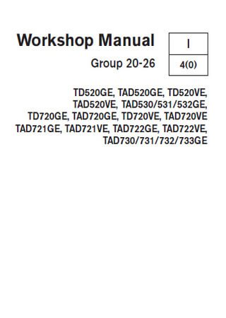
2,06 Мб
Руководство по ремонту двигателей Volvo Penta
Формат: pdf
-
Год:
2004
-
Страниц:
140
-
Язык:
английский
-
Размер:
2,06 Мб
-
Категории:
Двигатели Volvo
1,44 Мб
Двигатели Volvo D7, D12: Руководство по эксплуатации и
Формат: pdf
-
Год:
2004
-
Страниц:
204
-
Язык:
английский
-
Размер:
1,44 Мб
-
Категории:
Двигатели Volvo
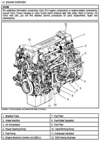
2 Мб
Руководство по обслуживанию двигателей Volvo D13, Detroit
Формат: pdf
-
Год:
2013
-
Страниц:
51
-
Язык:
английский
-
Размер:
2 Мб
-
Категории:
Двигатели Volvo
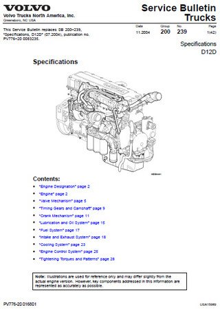
1 Мб
Руководство по обслуживанию двигателей Volvo D12D
Формат: pdf
-
Год:
2004
-
Страниц:
42
-
Язык:
английский
-
Размер:
1 Мб
-
Категории:
Двигатели Volvo
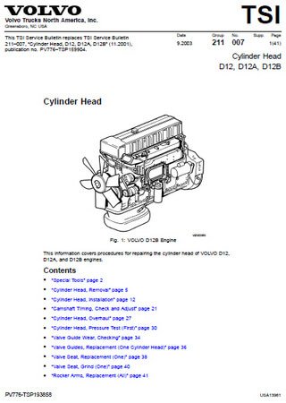
0,6 Мб
Руководство по обслуживанию двигателей Volvo D12, D12A, D12B
Формат: pdf
-
Год:
2003
-
Страниц:
41
-
Язык:
английский
-
Размер:
0,6 Мб
-
Категории:
Двигатели Volvo
![]() Скачать бесплатно руководства по ремонту автомобилей в PDF формате
Скачать бесплатно руководства по ремонту автомобилей в PDF формате
Электронные книги : Руководства по ремонту, советы по эксплуатации, ремонту двигателей и электрооборудования, технические характеристики различных марок автомобилей
Скачать бесплатно электронные книги , инструкции и руководства по ремонту автомобилей, книги по ремонту и эксплуатации автомобилей, и другие автокниги, а также автокаталоги, карты, атласы, учебные пособия для подготовки водителей, CD диски по автомобильной тематике, каталоги запчастей для автомобилей, автокниги по ремонту, эксплуатации и обслуживанию автомобилей, как российских, так и зарубежных производителей, издательств технической литературы, таких как Третий Рим, Арус, Монолит, Мир Автокниг, За рулем, Легион Автодата
Acura, Alfa Romeo, Audi, Beifan Benchi, BMW, Buick, BYD, Cadillac, Chery, Chevrolet, Chrysler, Citroen, Dacia, Dadi, Daewoo, DAF, Daihatsu, Derways, Dodge, Dong Feng, FAW, Fiat, Ford, Foton, Freightliner, Geely, GMC, Great Wall, Groz, Hania, Hino, Holden, Honda, HOWO, Hummer, Hyundai, Infiniti, International, Iran, Isuzu, Iveco, Jeep, Kenworth, Kia, Lancia, Land Rover, Range Rover, Lexus, Lifan, Lincoln, MAN, Maxus, Mazda, Mercedes-Benz, Mercury, Mini, Mitsubishi, Nissan, Oldsmobile, Opel, Peterbilt, Peugeot, Plymouth, Pontiac, Porsche, Renault, Rover, Saab, Samsung, Saturn, Scania, Scion, Seat, Setra, Shaanxi, Skoda, SsangYong, Subaru, Suzuki, TagAZ, Tata, Toyota, VolksWagen, Volvo, Vortex, ZAZ, АЗЛК, Москвич, ВАЗ, Lada, ГАЗ, Донинвест, ЗИЛ, Иж, КамАЗ, КрАЗ, ЛиАЗ, ЛуАЗ, МАЗ, МЗКТ, ПАЗ, УАЗ, УРАЛ
Книга: VOLVO FL / FE дизель с 2006 г.в., ремонт, техническое обслуживание
Подробное руководство по ремонту и техническому обслуживанию автомобилей Volvo FL и FE с 2006 года выпуска
Книга: VOLVO FH дизель с 2005 г.в., ремонт
Руководство по ремонту грузовых автомобилей Volvo серии FH выпускаемых с 2005 года с дизельным двигателем D13A.
Книга: VOLVO FH дизель с 2002 г.в., ремонт, эксплуатация, техническое обслуживание
Руководство по ремонту, эксплуатации и техническому обслуживанию грузовых автомобилей Volvo серии FH 2002 года выпуска с двигателями D12, D13.
Книга: VOLVO FM дизель с 2002 г.в., ремонт, эксплуатация, техническое обслуживание
Руководство по ремонту, эксплуатации и техническому обслуживанию грузовых автомобилей Volvo серии FM 2002 года выпуска с двигателями D9, D11, D12, D13.
Книга: VOLVO FH12 дизель с 2002 г.в., ремонт
Руководство по ремонту грузовых автомобилей Volvo серии FH 12 выпускаемых с 2002 года.
Книга: VOLVO FH / FM дизель эксплуатация, техническое обслуживание
Руководство по эксплуатации и техническому обслуживанию грузовых автомобилей Volvo FH / FM с 2002 года выпуска.
Книга: VOLVO VN / VHD дизель с 2002 по 2007 г.в., эксплуатация, ремонт, техническое обслуживание
Руководство по ремонту, эксплуатации и техническому обслуживанию грузовых автомобилей VOLVO серии VN и VHD, имеющих любое из следующих обозначений:
VNL780, VNL670, VNL630, VNL430, VNL300 (дневная кабина), VNM630, VNM430, VNM 200 (дневная кабина), VHD200B (приводной задний мост), VHD200F (приводной передний мост).
Книга: VOLVO FL6 / FL / FE дизель с 2000 + рестайлинг с 2010 г.в., ремонт, эксплуатация, техническое обслуживание
Подробное пособие по ремонту, эксплуатации и техническому обслуживанию грузовых автомобилей марки Volvo серий FL6 с 2000 г.в., FL с 2006 г.в, а также FE c 2006 г.в., с дизельными двигателями D6B, D7E, D7F, включая модификации с 2010 года выпуска.
Книга: VOLVO FL6 дизель с 2000 г.в., ремонт и техническое обслуживание
Руководство по ремонту грузовых автомобилей Volvo FL6 с 2000 года выпуска с 6-ти цилиндровыми дизельными двигателями.
Книга: VOLVO FH12 дизель 1998 — 2005 г.в., ремонт, техническое обслуживание
Руководство по ремонту и техническому обслуживанию грузовых автомобилей Volvo серии FH 12 выпускаемых с 1998 по 2005 годы.
Книга: VOLVO FH12 дизель с 1998 г.в., коды неисправностей электросхемы
Руководство по поиску неисправностей грузовых автомобилей Volvo серии FH 12 выпускаемых с 1998 года. Электросхемы.
Книга: VOLVO VNL и VNM дизель с 1996 по 2002 г.в., ремонт, эксплуатация, техническое обслуживание
Руководство по ремонту, эксплуатации и техническому обслуживанию грузовых автомобилей VOLVO серии VNL и VNM с 1996 по 2002 годы выпуска.
Книга: VOLVO FL6 дизель ремонт, эксплуатация, техническое обслуживание
Руководство по ремонту и эксплуатации грузовых автомобилей Volvo FL6 с 1993 года выпуска с 6-ти цилиндровыми дизельными двигателями.
Книга: VOLVO FH12 дизель с 1993 по 2005 г.в., ремонт, техническое обслуживание
Руководство по ремонту и техническому обслуживанию грузовых автомобилей Volvo серии FH12 и их модификаций. Руководство по ремонту двигателей грузовых автомобилей. Рассмотрены три поколения автомобилей, выпускавшихся разными заводами в период с 1993 по 2005 годы выпуска.
Книга: VOLVO F12 дизель с 1988 г.в., ремонт, эксплуатация, техническое обслуживание
Руководство по ремонту, эксплуатации и техническому обслуживанию грузовых автомобилей Volvo series F12 с 1988 года выпуска.
Книга: VOLVO F12 дизель 1979-1987 г.в., ремонт, техническое обслуживание
Руководство по ремонту грузовых автомобилей Volvo series F12 с 1979 по 1987 годы выпуска.
Книга: VOLVO FM9 дизель ремонт
Руководство по ремонту грузовых автомобилей Volvo серии FM9.
Тип двигателя: D9A260/D9A300/D9A340/D9A380 Объем двигателя: 9.4 л.Мощность: 260/300/340/380 л.с.
Книга: Двигатели CATERPILLAR модели C-15 дизель ремонт, эксплуатация, техническое обслуживание
Руководство по ремонту, эксплуатации и техническому обслуживанию двигателей Caterpillar моделей C-15.
Книга: VOLVO VN дизель устройство каталог деталей
В настоящем издании представлен каталог основных деталей и сборочных единиц грузовых автомобилей VOLVO VN.
Книга: VOLVO FH12 дизель ремонт, эксплуатация, техническое обслуживание каталог деталей
Руководство по ремонту, техническому обслуживанию и эксплуатации грузовых автомобилей Volvo серии FH 12. Приведен полный каталог основных деталей и сборочных единиц.
Книга: VOLVO FH / FM дизель ремонт, эксплуатация, техническое обслуживание Том 2
Руководство по ремонту и эксплуатации грузовых автомобилей Volvo FH / FM с 9- и 13-литровыми двигателями.
Книга: VOLVO FH / FM дизель ремонт, эксплуатация, техническое обслуживание Том 1
Руководство по ремонту и эксплуатации грузовых автомобилей Volvo FH / FM с 9- и 13-литровыми двигателями.
Книга: VOLVO серий VN WX WG AC дизель техническое обслуживание
Руководство по техническому обслуживанию грузовых автомобилей Volvo серий VN, WX, WG, AC.
Книга: VOLVO VNL и VNM дизель эксплуатация, техническое обслуживание
Руководство по эксплуатации и техническому обслуживанию грузовых автомобилей VOLVO серии VNL и VNM, имеющих любое из следующих обозначений: VNL42T, VNM42T, VNL42, VNM42, VNL64T, VNL64, VNM64.
Книга: VOLVO FH12 дизель ремонт, эксплуатация,
Руководство по ремонту, техническому обслуживанию и эксплуатации грузовых автомобилей Volvo серии FH 12 выпускаемых с 1993 года.
Книга: VOLVO F12 дизель с 1988 г.в., ремонт, эксплуатация, техническое обслуживание
Руководство по ремонту и эксплуатации грузовых автомобилей Volvo series F12 с 1988 года выпуска.
Книга: VOLVO FL7 дизель ремонт, техническое обслуживание
Руководство по ремонту и эксплуатации грузовых автомобилей Volvo FL7 с 1985 года по 1993 год выпуска с двигателями серий TD 71 и TD 73.
Книга: VOLVO F16 / TF16 дизель ремонт
Руководство по ремонту грузовых автомобилей VOLVO F16 / TF16.
Книга: VOLVO FM12 дизель ремонт
Руководство по ремонту грузовых автомобилей Volvo серии FM 12.
Книга: VOLVO XC60 бензин / дизель с 2008 г.в., ремонт, эксплуатация, техническое обслуживание
Рекомендации специалистов по диагностике, ремонту и поддержанию в хорошем техническом состоянии автомобилей Volvo XC60, укомплектованных бензиновыми и дизельными двигателями.
Книга: VOLVO S60 бензин / дизель с 2010 г.в., ремонт, эксплуатация, техническое обслуживание
Руководство по ремонту, техническому обслуживанию и эксплуатации Volvo S60 с 2010 года выпуска, с бензиновыми и дизельными двигателями.
Книга: VOLVO XC70 / V70 бензин / дизель с 2007 + рестайлинг с 2009 и 2011 г.в., ремонт, эксплуатация, техническое обслуживание
Издание содержит справочную информацию об эксплуатации, ремонте и обслуживании автомобиля Volvo XC70 / V70 с 2007, 2009, 2011 года выпуска, с бензиновыми и дизельными моторами: 1.6, 2.0, 2.5, 3.0, 3.2, 2.0D, 2.4D.
Книга: VOLVO S80 бензин / дизель с 2007 г.в., ремонт, эксплуатация, техническое обслуживание
Технические сведения от практиков об устройстве, эксплуатации и ремонте автомобилей Volvo S80 с рабочим объёмом бензиновых двигателей 2,0 и 3,0 литра, и дизельных 2,4.
Книга: VOLVO C30 бензин / дизель с 2006 г.в., ремонт, эксплуатация, техническое обслуживание
Новое издание с исчерпывающей справочной информацией по а/м Volvo C30 с установленными на них бензиновыми и дизельными двигателями.
Книга: VOLVO XC90 бензин / дизель с 2006 г.в., ремонт, эксплуатация, техническое обслуживание
В книге рассматриваются особенности эксплуатации и техобслуживания Volvo XC90 с такими двигателями, как B5254T2, B8444S, B6324S (бензин) и D5244T4 (дизель).
Книга: VOLVO S40 и V50 бензин / дизель с 2004 г.в., ремонт, эксплуатация, техническое обслуживание
Квалифицировано о ремонте, эксплуатации и техническом обслуживании автомобилей Volvo S40 (кузов седан) и Volvo V50 (кузов универсал) с различным рабочим объёмом бензиновых двигателей.
Книга: VOLVO S40 и V50 бензин / дизель с 2003 г.в., ремонт, эксплуатация, техническое обслуживание
Практические советы по обслуживанию автомобилей Volvo S-40 и V-50. Всё, что необходимо знать о моделях с рабочим объёмом бензиновых двигателей 1.6, 1.8, 2.4 и 2.5 литра и дизельных 2.0 литра.
Книга: VOLVO XC90 бензин / дизель с 2003 г.в., ремонт, эксплуатация, техническое обслуживание
Качественное и подробное руководство по автомобилям Volvo XC90 с различного объёма турбированными бензиновыми и дизельными двигателями. Рассматриваются модели, оборудованные 4-, 5- и 6-ступенчатой коробкой передач. Для специалистов автосервиса, а также автолюбителей.
Книга: VOLVO XC90 бензин / дизель с 2003 г.в., ремонт, эксплуатация, техническое обслуживание
Проиллюстрированное издание поможет разобраться в тонкостях диагностики и техобслуживания Volvo XC90 c различным рабочим объёмом бензиновых и дизельных двигателей.
Книга: VOLVO XC90 бензин / дизель с 2002 + рестайлинг с 2006 г.в., ремонт, эксплуатация, техническое обслуживание в ЦВЕТНЫХ фотографиях
Вся важная и полезная информация о техническом устройстве, эксплуатации и ремонте автомобилей Volvo XC-90 с рабочим объёмом бензиновых двигателей 2.5, 3.2 и 4.4 литра и турбодизелем 2.4 литра.
Книга: VOLVO XC90 бензин / дизель 2002-2009 г.в., ремонт, эксплуатация, техническое обслуживание
Руководство по ремонту, устройству и техническому обслуживанию автомобилей Volvo XC-90 с бензиновыми 2.5, 2.9, 3.2, 4.4 литра и дизельными 2.4 литра двигателями.
Книга: VOLVO XC70 бензин / дизель с 2001 г.в., ремонт, эксплуатация, техническое обслуживание
Руководство по ремонту, эксплуатации и техническому обслуживанию автомобилей Volvo XC70 с 2001 года выпуска, с бензиновым двигателем с турбонаддувом объемом 2.5 л, а также турбированным дизельным двигателем объемом 2.4 л, развивающими мощность 210 и 163 л.с соответственно.
Книга: VOLVO V70 / XC70 бензин / дизель 2000-2007 г.в., ремонт, эксплуатация, техническое обслуживание
Руководство по ремонту и эксплуатации Volvo V70 / XC70, 2000-2007 годы выпуска, с бензиновыми 2.0, 2.3, 2.4, 2.5 и дизельными 2.4 двигателями.
Книга: VOLVO S60 / S60T5 / S60R бензин / дизель 2000-2009 г.в., ремонт, эксплуатация, техническое обслуживание
Руководство по ремонту, эксплуатации и техническому обслуживанию автомобилей Volvo S60 2000-2008 годы выпуска, с бензиновыми двигателями объемом 2.0, 2.3, 2.4, 2.5, л. и дизельными двигателями объемом 2.4 литра.
Книга: VOLVO S60 бензин / дизель 2000-2008 г.в., ремонт, эксплуатация, техническое обслуживание
Руководство по ремонту, эксплуатации и техническому обслуживанию автомобилей Volvo S60 2000-2008 годы выпуска, с бензиновыми и дизельными двигателями.
Книга: VOLVO XC70 / V70 / V70R эксплуатация, техническое обслуживание
Руководство по эксплуатации и техническому обслуживанию автомобилей Volvo XC70 / V70 / V70R. Данная книга — подробная инструкция по эксплуатации и техническому обслуживанию автомобиля Вольво XC70 / V70 / V70R.
Книга: VOLVO V70 / XC / XC70 бензин / дизель 2000-2007 г.в., ремонт, эксплуатация, техническое обслуживание
Руководство по ремонту и эксплуатации Volvo V70 / XC / XC70, 2000-2007 годы выпуска, с бензиновыми 2.3 20V, 2.4 20V, 2.4 20V Turbo, 2.5 20V R, 2.5 20V Turbo и дизельными 2.4 TD двигателями.
Книга: VOLVO V70 / S80 бензин / дизель 1998-2005 г.в., ремонт, эксплуатация, техническое обслуживание
Руководство по ремонту, эксплуатации и техническому обслуживанию автомобилей Volvo V70 2000-2004 годы выпуска и S80 1998-2005 годы выпуска, с бензиновыми двигателями рабочим объемом 2,0 (1984 см3), 2,3 (2319 см3) и 2,5 л (2521 см3), а также дизельными двигателями объемом 2,4 л (2401 см3) с турбонаддувом D5.
Книга: VOLVO S70 / V70 / C70 бензин 1996-1999 г.в., ремонт, эксплуатация, техническое обслуживание
Руководство по ремонту и техническому обслуживанию автомобиля Volvo S70, V70, C70 с 1996-1999 годы выпуска, с бензиновыми двигателями рабочим объемом 2,0 (1984 см3), 2,3 (2319 см3) и 2,4 л. (2435 см3), с турбонаддувом и без него, включая версии Т5.
Книга: VOLVO S40 / V40 бензин 1996-2004 г.в., ремонт, эксплуатация, техническое обслуживание
Руководство по ремонту, обслуживанию и эксплуатации автомобилей Volvo S40 (седан) и V40 (универсал) 1996?03/2004 годы выпуска, с бензиновыми двигателями (включая турбированные и GDI) рабочим объемом 1,6 (1588 см3), 1,8 (1731, 1783 и 1834 см3), 1,9 (1855 см3) и 2,0 л. (1948 см3), включая специальные, малосерийные версии и модификацию Т4.
Книга: VOLVO S40 / V40 бензин / дизель 1996-2004 г.в., ремонт, эксплуатация, техническое обслуживание
Руководство по ремонту и эксплуатации автомобилей Volvo S40 / V40 1996-2004 годы выпуска, с бензиновыми и дизельными двигателями.
Книга: VOLVO S40 / V40 бензин 1996-2000 г.в., ремонт, эксплуатация, техническое обслуживание
Руководство по ремонту, устройству и техническому обслуживанию автомобилей Volvo S40 / V40 1996-2000 годы выпуска, с бензиновыми двигателями 1,8 л. и 2,0 л.
Книга: VOLVO 240 / 740 / 760 / 780 / 940 / 960 бензин с 1990 г.в., ремонт, эксплуатация, техническое обслуживание
Подробное описание работ ремонта, эксплуатации и технического обслуживания автомобилей Volvo 240 / 740 / 760 / 780 / 940 / 960 с 1990 года выпуска. Представлены модели с бензиновыми моторами 2.3, 2.8, 2.9 л.
Книга: VOLVO 850 бензин 1992-1996 г.в., ремонт, эксплуатация, техническое обслуживание
Руководство по ремонту и эксплуатации автомобилей Volvo 850 1992-1996 годы выпуска, с кузовами седан и универсал, с бензиновыми двигателями B5202S, B5204S, B5234S, B5234T, B5252S, B5254S.
Книга: VOLVO 940 / 960 бензин 1990-1997 г.в., ремонт, техническое обслуживание
Руководство по ремонту и техническому обслуживанию автомобилей Volvo 940, 960 1990-1997 годы выпуска, с бензиновыми двигателями рабочим объемом 2,0, 2,3, 2,5, 2,9 л.
Книга: VOLVO 440 460 480 бензин 1987-1992 г.в., ремонт, эксплуатация, техническое обслуживание
Руководство по ремонту, обслуживанию и эксплуатации автомобилей Volvo 440, 460, 480 купе, седан и хэтчбэк, с бензиновыми двигателями OHC 1721 см3 и 1794 см3, включая модели с турбонаддувом, каталитическим преобразователем и различными комплектами систем снижения токсичности отработавших газов.
Книга: VOLVO 440 460 480 бензин 1987-1992 г.в., ремонт, техническое обслуживание
Руководство по ремонту и техническому обслуживанию автомобилей Volvo 440, 460, 480 1987-1992 годы выпуска, с бензиновыми двигателями рабочим объемом 1,7 и 1,8 л., включая турбо.
Книга: VOLVO 740 760 бензин с 1982-1991 г.в., ремонт, техническое обслуживание
Руководство по ремонту и обслуживанию автомобилей Volvo 740 и 760 с кузовами седан и универсал, 1982-1991 годы выпуска, с бензиновыми двигателями
Книга: VOLVO 740 760 бензин / дизель 1982-1991 г.в., ремонт, техническое обслуживание
Руководство по ремонту и техническому обслуживанию автомобилей Volvo 740 и 760 (включая Turbo и специализированные модели) 1982-1991 годы выпуска, с бензиновыми двигателями объемом 1986 см3, 2316 см3 и 2849 см3 и модели с дизельными двигателями объемом 2383 см3.
Книга: VOLVO 340 343 345 360 бензин / дизель с 1976 г.в., ремонт, эксплуатация, техническое обслуживание
Руководство по ремонту и эксплуатации автомобилей Volvo 340, 343, 345, 360 с 1976 года выпуска, с бензиновыми 4-х цилиндровыми двигателями B13/14, B172, B19, B200 рабочим объемом 1,3, 1,4, 1,7, 2,0 л. и дизельными 4-х цилиндровыми двигателями D16 объемом 1,6 л.
Книга: VOLVO XC90 бензин / дизель с 2002 г.в., ремонт, эксплуатация, техническое обслуживание
Руководство по ремонту, устройству и техническому обслуживанию автомобилей Volvo XC90 с 2002 года выпуска, с бензиновыми и дизельными двигателями.
Книга: VOLVO S60 / V70 бензин / дизель с 2001 г.в., ремонт, эксплуатация, техническое обслуживание
Руководство по ремонту, эксплуатации и техническому обслуживанию автомобилей Volvo S60 / V70, с 2001 года выпуска, в том числе рестайлинг 2004 года, с бензиновыми двигателями рабочим объемом 2,4 л. (20V D5), 2,4 л. (20V T5), 2,4 л. (20V Turbo и Turbo R), 2,4 л. (Bi-Fuel), а также дизельным двигателем рабочим объемом 2,4 л. (20V TD).
Книга: VOLVO 340 343 345 360 бензин / дизель 1976-1989 г.в., ремонт, техническое обслуживание
Руководство по ремонту и техническому обслуживанию автомобилей Volvo 340, 344, 345, 360. Модели 1976-1989 годы выпуска, с бензиновыми двигателями объемом 1397 см3, 1721 см3, 1986 см3 и дизельным двигателем объемом 1595 см3.
Книга: VOLVO 850 бензин 1992-1996 г.в., ремонт, техническое обслуживание
Руководство по ремонту и техническому обслуживанию автомобилей Volvo 850 1992-1996 годы выпуска, с 5-цилиндровыми бензиновыми двигателями рабочим объемом 1984, 2319 и 2435 см3, моделей B5202S, B5204S, B5234S, B5234T, B5252S, B5254S, с кузовами седан и универсал.
Книга: VOLVO S60 эксплуатация, техническое обслуживание
Руководство по эксплуатации и техническому обслуживанию автомобилей VOLVO S60. Данная книга — подробная инструкция по эксплуатации и техническому обслуживанию автомобиля Вольво С60.