Руководство на английском языке по техническому обслуживанию и ремонту Fiat Marea и Fiat Marea Weekend.
- Автор: —
- Издательство: Fiat Auto
- Год издания: —
- Страниц: 846
- Формат: PDF
- Размер: 20,1 Mb
Руководство по эксплуатации и ремонту Fiat Marea с 1996 года выпуска с бензиновыми и дизельными двигателями.
- Автор: —
- Издательство: Чижовка
- Год издания: —
- Страниц: 378
- Формат: PDF
- Размер: 88,6 Mb

-
Contents
-
Table of Contents
-
Bookmarks
Quick Links
Related Manuals for Fiat Marea Weekend
This manual is also suitable for:
Marea
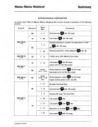
Service Manual Composition
1
Characteristics
3
Typical Power Curves Obtained by EEC Method
3
Engine: Cylinder Block/Crankcase, Crankshaft and Associated Components
4
Description
4
Engine: Cylinder Head Assembly and Valve Gear Components
6
Timing Diagrams
6
Integrated Electronic Injection/Ignition System Components
7
Starter Motor
8
Starter Motor — Wiring Diagram and Typical Curves
9
Introduction and Technical Data
11
Identification Data
12
Weights
14
Note for Versions with Accessories:
14
Performance — Fuel Consumption
15
Dimensions
17
Capacities
19
Specifications of Fiat Lubricant Products
22
Specifications
23
Engine: Typical Curves
24
Power Curves Obtained through the CEE Method
24
Engine: Cylinder Head and Valve Gear Components
30
Engine: Lubrication
34
Engine: Cooling System
35
Engine: Fuel System
36
Test Bench Cycles for Overhauled Engines
38
Engine: Cylinder Block/Crankcase, Crankshaft and Associated
39
Engine: Counter- Balance Shafts
47
Engine: Supercharging
53
Clutch
54
Gearbox and Differential
55
Brakes
59
Steering
61
Wheels
62
Front Suspension
64
Rear Suspension
66
Electrical Equipment
68
Electrical Equipment: Starting
69
Electrical Equipment: Recharging
71
Electrical Equipment: Electronic Injection/Ignition
72
Special Tools
74
Table of Contents
91
Marengo
92
Introduction
92
Identification Data
92
Weights
93
Technical Data
94
Rear — Front Suspension
94
Index
96
Removing-Refitting
98
Removing-Refitting Power Unit
98
Replacing Auxiliary Shaft Drive Belt
109
Air Conditioning Compressor Drive Belt
111
Checking Valve Gear Timing
112
Removing-Refitting Timing Drive Belt
114
Replacing Timing Belt
115
Removing- Refitting Cylinder Head
120
Fitting Cylinder Head
122
Removing- Refitting Exhaust Manifold
124
Removing-Refitting Intake Manifold
125
Removing-Refitting Water Pump
127
Removing-Refitting Radiator
127
Procedure for Refilling Engine Cooling System
129
Method for Draining Circuit
129
Method for Refilling the Circuit
129
Engine Cooling System Components (Version with Heater)
130
Fuel System
134
Integrated Injection-Ignition System — M.marelli-Weber I.a.w.-49F
135
System Operating Strategies
135
Introduction
135
Injection-Ignition System Operating Diagram
136
Injection Management
137
Control of Mixture Concentration (Retro-Active Control)
138
Self-Adaptability
139
Starting and Post-Starting
139
When Cold
140
Connection to Automatic Transmission
140
Full-Load
140
Over-Run
141
Barometric Correction
141
Cut-Off
141
Acceleration
142
Protection against Excess Rpm
142
Electric Fuel Pump Drive
142
Injector Control
142
Ignition Management
143
Ignition Operating Diagram
144
Controlling Knock
146
Fiat Code Ignition Immobiliser Management
146
Radiator Fan Management
146
Engine Idle Control
147
Fuel Vapour Recirculation Management
147
Test Management
147
Heating/Ventilation System Management
148
Air Intake Circuit Management
150
Fuel Supply Circuit Diagram
151
Fuel Evaporation Control Circuit Diagram
152
Blow-By Gas Recirculation Diagram
153
Injection-Ignition System Wiring Diagram
154
Key to Injection — Ignition System Wiring Diagram Components
155
Engine Exhaust Assembly Diagram
156
Location of Injection-Ignition System Components
157
Key to Components
157
Injection — Ignition System Fuses and Relays
158
General System Protection Fuse
158
Fuses and Relay
158
Earth Points
158
Components of Injection-Ignition System
159
Injection-Ignition System Wiring
159
Data Acquisition and Coding Section
159
Microprocessor
160
ROM Memory (Read Only Memory)
160
RAM Memory (Random Access Memory)
160
EEPROM Memory (Electrical Erasable Programmable Read Only Memory)
160
Identifying Connections on Injection-Ignition Control Unit (Pin-Out)
162
Rpm and Tdc Sensor
163
Principle of Operation
163
Wiring Connector
164
Checking Gap
164
Checking Resistance
164
Knock Sensor
165
Throttle Body
166
Throttle Valve Position Sensor
167
Recovery
168
Engine Coolant Temperature Sensor
169
Engine Idle Speed Actuator
170
Motor Strategy
171
Removing-Refitting Engine Idle Control Actuator (Step Motor)
171
Intake Air Pressure and Temperature Sensor (T-Prt 03)
172
Automatic Diagnosis and Recovery
172
Electric Fuel Pump
173
Removing-Refitting Electric Fuel Pump
173
Fuel Manifold (Cb 168)
174
Carbon Filter
174
Fuel Vapour Cut-Off Solenoid (EC1)
175
Longitudinal Section through Fuel Vapour Cut-Off Valve
175
Multifunction Valve (Sirio 0175.00)
176
Vehicle Speed Sensor
177
Safety and Ventilation Valve
177
Injectors
178
Inertia Safety Switch
179
Components of Inertia Switch
179
Ignition Coils
180
Checking Winding Resistance
181
Primary Circuit
181
Secondary Circuit
181
Lambda Probe (Ntk 0Za334-A1)
182
Intake Air Quantity
182
Removing — Refitting Lambda Probe
184
Checks, Adjustments and Repairs to Injection-Ignition System
185
Adjusting Throttle Cable
185
Removing-Refitting Fuel Manifold and Injectors
185
Removing-Refitting Fuel Tank
187
Removing-Refitting Accelerator Cable
190
Checking Engine Idle Speed
191
Checking Concentration of Pollutant Emissions
191
Checking Idle Concentration of CO/HC Upstream of Catalytic Silencer
191
Checking CO and HC Levels at Exhaust
192
Checks on Fuel Feed Circuit
193
Checking Fuel Feed Pressure
193
Checking Fuel Feed Pressure Using a Tester
194
Checking Fuel Consumption
194
Fault Diagnosis
196
Error Recognition and Storage
196
Error Frequency Counter
196
Error Deletion
196
Communication between Control Unit and Tester
197
Displayed Parameters
197
List of Errors
197
Active Diagnosis
198
Introduction
201
General Diagram of Fuel System
202
Location of Fuel System Components
203
Input/Output Signals between Control Unit and Sensors/Actuators
204
Functional Diagram of the Fuel System
206
Air Temperature Sensor
207
Coolant Temperature Sensor
207
Injection Ntc
207
Gauge Ntc
207
Hot-Film Air Flowmeter
208
Wiring Diagram
210
Key to Wiring Diagram
211
Control Unit Pins
212
Bosch M1.5.5 Integrated Injection/Ignition System
215
Bosch M1.5.5 Injection/Ignition System Functional Diagram
216
System Management Strategies
219
Operating Principle
219
Management of the Injection
220
Controlling the Mixture Strength (Feed Back Control)
221
Starting and Operation When Cold
222
Operation in Full Load Conditions
222
Operation in Cut-Off Conditions
222
Management of the Fiat Code Ant-Theft Function
223
Rotation Speed Restricter
223
Electric Fuel Pump Operation
223
Operation of the Injectors
223
Management of the Ignition
224
Operation at High Temperatures
225
Operation in Cut off Conditions
225
Operation in Take-Off Conditions
225
Operation with the Engine Idling
225
Management of the Engine Idle Speed Control
226
Management of the Active Charcoal Filter
226
Management of the Climate Control System
227
Management of the Radiator Fan
228
Diagnostics
229
Actuators
229
Sensors
229
Location of Diagnostic Connector
229
Electrical/Electronic Circuit
230
Wiring
230
Layout of System Earth Points
230
BOSCH Ml .5.5 SYSTEM CONTROL UNIT PIN out
231
Engine Rpm and Tdc Sensor
237
Lambda Sensor
238
Resistance: 4.5+0.5 Ohm at 20 °C
238
Intake Air Temperature and Pressure Sensor
240
Power Assisted Steering Sensor
241
Detonation Sensor
241
Intake Circuit
243
Butterfly Casing
244
Fuel Supply Circuit
245
Fuel Circuit Diagram
245
Fuel Drip Tray Assembly
246
Fuel Filter
246
Fuel Pressure Regulator
246
Fuel Manifold
247
Emission Control Devices
249
Catalytic Silencer
249
Anti-Evaporation Circuit Diagram
251
Anti-Evaporation System Components
252
Multi-Purpose Valve
252
Charcoal Filter
253
Charcoal Filter Solenoid Valve
254
Checks, Adjustments and Repair Operations on the Bosch M1.5.5 System
255
Checking the Concentration of the Emissions
255
Checking Exhaust Concentration of CO and HC
256
Engine Idle Speed Check
256
Ignition Advance Check
256
Fuel Supply Circuit Pressure Check
257
Draining Supply Circuit Fuel Pressure
257
Checking Fuel Supply Pipe Seal
258
Injector Seal Check
259
Removing Test Equipment
260
Fuel Manifold and Injectors
263
Removing-Refitting Fuel Manifold
263
Removing-Refitting Injectors
264
Zeroing
266
Self-Learning
266
Accelerator Cable
266
Engine Idle Adjustment Actuator/Butterfly Position Sensor
267
Engine Control Unit
268
Engine
269
Hitachi Integrated Injection/Ignition System
271
Functional Diagram Showing Injection/Ignition System
272
Management of the Signals
275
Control of the Mixture Strength (Feed-Back Control)
277
Self-Adjustment
277
Operation When Cold
278
Operation in Acceleration Conditions
279
Operation in Deceleration Conditions
279
Management of the Fiat Code Anti-Theft Function
280
Rotation Speed Limiter
280
Fuel Pump Operation
280
Managment of the Ignition
281
Starting
282
Operation with Engine Idling
282
Control of Detonation
283
Management of the Engine Idle
284
Engine Started with Accelerator Pedal Released
284
Management of the Charcoal Filter
284
Managemeimt of the Radiator Fans
286
Version Without Climate Control
286
Version with Climate Control
286
Diagram Showing Engagement of Fans for Version with Air Conditioning
287
Recovery Strategy
288
Engine Side Wiring (A)
289
Vehicle Side Wiring (B)
289
Location of System Earth Points
289
Hitachi System Wiring Diagram Key
291
System Relays
291
Hitachi System Control Unit Pin-Out
292
Engine Rpm Sensor
294
Engine Timing Sensor
295
Air Flow Meter
296
Batteryfly Position Sensor
298
Diagram Showing Air Intake Circuit
302
Engine Idle Speed Adjustment Actuator
304
Diagram Showing Fuel Circuit
305
Fuel Drip Tray
306
Fuel Anti-Evaporation System
312
Float Valve
313
Charcoal Folter Solenoid Valve
313
Exhaust Gas Recirculation System (Blow-By)
314
Checks, Adjustments and Repair Operations on the Hitachi Mpi System
315
Checking Concentration of Emissions
315
Checks on Fuel Supply Circuit
317
Draining Supply System Fuel Pressure
317
Checking Fuel Supply Circuit Pressure
318
Checking the Injector Seal
319
Checking the Seal of the Injectors
319
Accelerator Control Cable
324
General Description of the Injection System
326
General Description of the Ignition System
326
Injection/Ignition System Functional Diagram
327
Injection/Ignition System Functions
328
Adjustment of Injection Times
329
Ignition Advance Adjustment
329
Fuel Cut-Off During Overrun
329
Engine Idle Speed Control
330
Restricting the Maximum Number of Revs (Protection Outside of Revs)
330
Controlling Combustion Via the Lambda Sensor
330
Fuel Vapour Recovery
331
Detonation Control
331
Phase Transformer Control
331
Inlet Manifold Control
331
System Self-Adjustment
332
Autodiagnosis
332
Connection with Engine Immobilizer Device (Fiat CODE)
332
Air Intake Circuit
333
Fuel Anti-Evaporation Circuit Diagram
336
Injection/Ignition System Wiring Diagram
339
Control Unit/Ignition Coil and Injector Connection
340
Location of Injection/Ignition System Components
341
Fuses and Relays
342
Main Fuses
342
Diagnostic Socket
343
Location of Diagnostic Socket
343
Injection/Ignition System Components
343
Injection/Ignition System Wiring
343
Identification of Control Unit Connections (Pin Out)
344
Ignition Coilens (0.221.504.014)
346
Checking Coil Primary Circuit Resistance
346
Electrical Specifications
346
Electrical Connections Wiring Diagram
346
Timing Sensor (0.232.101.026)
347
Connector Wiring
347
Checking the Resistance
348
Checking the Gap
349
Detonation Sensors
349
Injectors (0.280.155.770)
351
Accelerator Pedal Potentiometer
352
Brake Pedal Switch
352
Clutch Pedal Switch
352
Butterfly Casing Actuator
354
Lambda Sensor (B.258.040.092)
355
Speedometer Sensor
356
Phase Transformer
357
Diagram Showing Operation of Phase Transformer
358
Inertia Switch
360
Inertia Switch Components
360
Vapour Cut out Solenoid Valve
361
Checking the Concentration of Pollutant Emissions
363
Table Summarizing Pollutant Emission Tolerance Values
364
Cancelling the Error
366
Connection with the Diagnostic Equipment
366
Operations on Vehicle
375
Interventions on Car
376
Disconnect the Electrical Connections from
378
Undo the Fixing Nuts and Place the Diesel Filter Aside
379
Disconnect the Electrical Connection from the Fuel Temperature Sensor
380
Move the Fuel Return Manifold Aside
380
Removing-Refitting Pressure Pump
381
Removing — Refitting Accelerator Pedal Potentiometer
389
Adjusting Accelerator Pedal End of Travel
390
Fuel System Management Strategies
393
Fuel System Functional Diagram
394
Checking Quantity of Fuel Injected
395
Injection Advance Check
395
Injection Pressure Check
395
Check on Auxiliary Electric Fuel Pump
395
Control of Idle Speed
396
Maximum Speed Restriction Control
396
Maximum Torque Restriction Control
396
Fuel Temperature Control
396
Exhaust Fumes Control
397
Exhaust Gas Recirculation Control
397
Air Conditioning System Engagement Control
397
Engine Immobilizer Function Control
397
Injection System Wiring Diagram
398
Injection System Wiring Diagram Components
399
Injection Electronic Control Unit
400
Identification of Injection Control Unit Connections (Pin-Out)
400
Rpm Sensor
401
Timing Sensor
402
Fuel Temperature Sensor
404
Fuel Pressure Sensor
404
Heater Plugs Control Unit
407
Excess Pressure Sensor
408
Atmospheric Pressure Sensor
408
Immersed (Auxiliary) Electric Fuel Pump Assembly and Gauge
410
Pressure Pump
411
Pressurizing the Tank
412
Seal in the Case of Overturning
412
Turbocharger
415
Operation at Low Rotation Speeds
416
Operation at High Rotation Speeds
416
Exhaust Gas Circuit
416
Catalytic Converter
417
Exhaust Gas Recirculation
417
Egr Modulating Solenoid Valve
418
Introduction
422
Input/Output Signals between Control Unit and Sensors/Actuators
425
Air Temperature Sensor
428
Hot-Film Air Flowmeter
429
Wiring Diagram
431
Control Unit Pins
433
Anti-Lock Brakes (A.b.s. Lucas Varity Ebc 430)
434
Braking System
434
Electro-Hydraulic Control Unit
436
Electronic Control Unit
436
Identification of Electro-Hydraulic Control Unit Outlets
439
Wheel Rpm Sensors (Active)
440
Positioning of Front Wheel Sensor
441
Positioning of Rear Wheel Sensor
441
Warning Light Signalling A.B.S. Failure
442
EBA Function Failure Signal
442
Description of the Operation of the Anti-Lock Brakes
443
Rest Position
443
Pressure Increase Stage
444
Pressure Maintenance Stage
445
Pressure Reduction Stage
446
Diagram Showing A.b.s. Hydraulic System
448
EBA Function (Electronic Brake Apportioning)
449
Eba Operation
450
Wiring Diagram for Lucas Varity Ebc 430 System
451
Auxiliary Units
453
Climate Control
453
Climate Control
455
Additional Heater
457
Location of Coolant Heater Plugs Inside the Vehicle
457
Location of Climate Control System Components
459
Jtd Engine Types
459
1242 16V ENGINE TYPE
460
Compressor
461
Scroll Compressor
462
Compression Mechanism
463
Saimden Sd7V16 Compressor
464
Denso 7Sb16 Compressor
465
Topping up Oil Level
466
Quantity and Type of Oil Contained in the Compressor
466
Other Compressors
466
Four Stage Pressure Switch
467
Location of Components on Vehicle
471
Location of Relays and Fuses on Vehicle
472
Location of Control Units and Tester Sockets (Engine Bay)
473
Electrical System
474
Thermostaticaly-Adjusted Heater/Air Conditioner
480
Thermostatically-Adjusted Heater/Air Conditioner
481
Versions Without Air Conditioner
482
Engine Cooling System
482
Engine Cooling Fan Low Speed Relay
483
Power Fuse Protecting Engine Cooling Fan
483
Engine Cooling Fan
483
Heater Unit Cables Connection
483
Versions with Air Conditioner
484
Engine Cooling System — Coolant Temperature Gauge
484
Location of Components
484
Front Left/Engine Cables Connection
485
Connection between Front Left Cable/Cable on Relay Bracket
485
Fuel Injection/Ignition Electronic Control Unit
485
Instrument Panel
489
Stop Lights Switch
489
Anti-Lock Braking System and Warning Light
489
Electrohydraulic Unit for Anti-Lock Braking System (A.B.S.)
489
Dashboard/Front Cables Connection
491
Low Brake Fluid Level Sensor
491
Air Conditioner Cables Connection
491
Compressor for Air Conditioner
494
Fuel Injection Relay
494
Ignition Coils Assembly
494
Sensor on Rear Right Wheel for Anti-Lock Braking System (A.B.S.)
495
Nection/Ignition Electronic Control Unit (1581)
496
4-Stage Pressure Switch
498
Electric Fan Resistor Connection
498
Instrument Panel Connections (TD Engine)
502
Engine Cooling Fan Relay
507
Connection between Left Front Cable/Cable on Relay Holder Bracket
507
Protection and Safety Devices
515
Main Supplies Wiring Diagram (Petrol Engine Types)
516
Main Supplies Wiring Diagram (Diesel Engine Types)
517
Front View of Control Unit and Location of Fuses
518
Rear View of Control Unit and Location of Relays
518
Description of Cables and Connectors
519
List of Fuses and Major Protected Circuits
521
Supplementary Fusebox
522
Location of Relays and Fuses on the Vehicle
523
Location of Relays and Fuses on the Car (Passenger Compartment)
525
Location of Control Units and Testing Sockets
526
Location of Connection Bridges
529
Radio System
530
Car Radio System
531
General Description
531
Radio Select
531
Cassette Select
531
Switching on Car Radio
532
Switching On/Off When the Engine Is Started/Stopped
532
Selecting Radio/Cassette/Compact Disc Functions
532
Pause Function
533
VOLUME Adjustment
533
Adjusting the Balance between Front and Rear Speakers (FADER)
534
LOUDNESS Function
534
MUTE Function
534
Radio Function
534
Function Selection
535
Band Selection
535
RDS Stations Automatic Search and Tuning
536
DX Function
536
Automatic Storing of Stations
536
Manual Station Storage
537
Listening to Stored Stations
537
TP Function (TRAFFIC PROGRAM)
537
Setting the TP (Traffic Program) Function Volume
538
Eon (Enhanced Other Network)
539
PTY Function
539
Automatic PTY Search
539
Storing Types of Programme Required on the Station Selection Buttons
539
Tuning to the Type of Programme Using the List
540
List of Available Programme Types
540
WEATHER: Weather Forecasts
540
Alternative Frequency (AF)
540
Cassette Player
541
Activating the Cassette Player
541
Inserting the Cassette
541
Changing Cassette Side
541
Fast Forward / Rewind
542
Search for Previous / Next Track
542
DOLBY B Function
543
Ejecting the Cassette
543
Pausing Cassette Playback Temporarily
543
Compact Disc Player Function
544
Filling the CD Magazine
544
Inserting the Magazine into the CD Player
544
Removing the Cds from the Magazine
545
CD Playback
545
Possible Error Messages
546
CD Selection
546
Track Search (Forward / Back)
546
Scanning the Tracks on the Selected
547
Fast Forward and Rewind
547
Repeating Current Track
547
Repeating Tracks from the Selected CD
547
Turning off the CD Function
548
Displaying CD Player Status
548
Expert Control Level
549
List of Possible EXPERT Adjustments
549
Selecting and Altering the Adjustments Using EXPERT Level Control
549
Setting the TIME
549
Minimum Traffic Information Volume
550
Activation / Deactivation LNR
550
Automatic Programme Change (REGIONAL)
550
Limiting the Switch-On Volume
550
Theft Protection
551
Switching off the Sound When the Car Phone Is in Use
551
Telephone Input Sensitivity
551
Secret Code
551
Deactivating the Code
552
Reactivating the Car Radio by Inputing the Code
552
Connections
553
Partial View of Car Radio Rear Section
553
Car Radio Tape Player Model as 182 M
554
Switching on Radio
556
BASS and TREBLE Adjustment
557
Adjusting Balance between Left and Right Speakers (BALANCE)
557
Adjust Balance Betwen Left and Right Speakers (FADER)
558
Tuning and Intelligent Automatic Search
559
RDS Automatic Tuning and Search
559
Tuning and Manual Storing of a Station
560
TP (Traffic Program) Function Volume Level Preset
561
EON (Enhanced Other Network) Function
562
TIME Setting
566
Synchronising the Watch
566
Automatic Program Change (REGIONAL)
567
LOC Function
567
MONO Function
567
Limiting the Volume at Start-Up
568
Funzione FADER
568
BOOSTER Activation / Deactivation Delay
569
Activation / Deactivation Via the Vehicle Ignition Switch
569
Technical Information
569
Aerial
569
Programming the Ignition Key
571
Fiat CODE
574
CONTROL PANEL (from November 1999)
575
Rear Side (the Connector Sockets Are Shown)
577
Smart Warning Lights
578
Changing Bulbs
578
Location of Caps and Replaceable Bulbs on Instrument Panel
579
Cable Colour Code
582
Polyelliptical Headlamps
583
Reflector Headlamps
583
Power Fusebox
584
Junction Unit
585
Dipped Headlamps Relay Feed
587
Steering Column Switch Unit
589
Left Front Earth
589
Ignition Switch
592
Connection between Right/Left Front Cables
592
Left No. Plate Light
592
Right No. Plate Light
592
Left Facia Earth
594
Hazard Warning Lights Switch Unit
594
Windscreen Wiper Motor
594
Facia/Rear Lead Connection
594
Front/Fog Lamp Lead Connection
596
Left Fog Light
596
Right Fog Light
596
Fog Lamp Control Relay
596
Switch Control Panel
597
Connection between Dashboard/Left Front Door Cables
597
Connection between Dashboard/Right Front Door Cables
598
Heated Rear Windscreen
598
Brake Lights Control Switch
598
Additional Brake Light
598
Right Dashboard Earth
599
Headlamp Alignment Control Unit
599
Left Low Tone Horn
599
Right High Tone Horn
599
Radio Receiver with Clock
600
Left Front Speaker (Tweeter)
600
Right Front Speaker (Tweeter)
600
Speaker in Left Front Door
600
Front/Engine Lead Connection
601
Fuel Gauge Unit
603
Control Panel Light Dimmer
603
Luggage Compartment Light
603
Luggage Compartment Light
604
Cigar Lighter
604
Connection between Dashboard/Front Cables
605
Right Front Electric Window Motor
605
Left Front Electric Window Motor
605
Left Rear Electric Window Motor
606
Rear/Left Rear Door Lead Connection
606
Right Rear Electric Window Motor
606
Connection between Rearl/Right Rear Door Cables
607
Insufficient Brake Fluid Level Sensor
607
Signalling
607
Electric Sun-Roof Lead Connection
607
Power Fuse for Anti-Lock Brakes
608
Electric Headlamp Washer Pump
608
Headlamp Washer Intermittence
608
Alarm Electronic Control Unit
608
Central Locking Remote Control Receiver
609
Vehicle Interior Front Courtesy Light
609
Left Rear Central Locking
609
Right Rear Central Locking
609
Left Front Central Locking
610
Right Front Central Locking
610
Air Bag Electronic Control Unit
610
Passenger Air Bag
611
Driver’s Air Bag
611
Connection between Air Bag/Dashboard Cables
611
Three Stage Pressure Switch
612
Engine Cooling Fan High Speed Timer
612
Air Conditioning Compressor Relay Feed
613
Connection between Left Front Cale/Cable on Relay Holder Bracket
615
Petrol Vapour Cut out Solenoid Valve
617
Connection between Rear/Driver’s Heated Seat Cables
617
2Nd Detonation Sensor
617
Idle Adjustment Actuator
619
Tester Socket for Injection System
619
Injection/Ignition Control Unit (1242)
619
Heated Lambda Sensor
620
Alternator
620
Potentiometer on Butterfly Valve
622
Compressor for Air Conditioning
622
Earth for Electronic Injection
622
Injection System Relay Feed
623
Relay for Lambda Sensor, Electric Fuel Pump, Injectors
624
Injection System Protective Fuse
624
Fuse Protecting Injection System
625
Coolant Temperature Sensor for Injection System
625
Coolant Temperature Sensor for Sensor
626
Reversing Lights Control Switch
626
Injection/Ignition Electronic Control Unit (1747)
626
Ignition Power Module
627
Sensor on Right Front Wheel (A.B.S.)
631
ABS Hydraulic Control Unit
631
Right Brake Pad Wear Sensor Cable Connection
631
Injection/Ignition Electronic Control Unit (1998)
632
Variable Valve Timing
632
Injection/Injector Braid Lead Connection
633
Glow Plug Preheating Control Unit
634
Car Interior Climate Control Fan
634
Intake Air Flap Control Actuator
635
Frost Sensor
635
Earth for Climate Control System
635
RP Sensor
635
Engine Cut out Electrostop (TD)
636
Clock Spring Connector
636
Earth for Compressor
636
Thermal Switch on Water Pump
636
Electric Rear Windows Control Unit
637
Connection between Air Bag/Left Pretensioner Cables
637
Left Pretensioner
637
Right Pretensioner
637
Connection between Automatic Transmission/Engine Cables
639
Climate Control Unit
639
Electronic Speed Transformer for Climate Control Fan
639
Mixing Air Control Actuator
639
Treated Air Temperature Sensor
640
Temperature Adjustment Switch
640
MAX-DEF Microswitch
640
Tailgate Locking/Unlocking Actuator
640
Automatic Transmission Control Unit
641
Connection between Automatic Transmission/Front Cables
641
Connection between Automatic Transmission/Dashboard Cables
641
Ignition Switch Electro-Magnet
642
Automatic Transmission System Protective Fuse
642
Starting Go Ahead Relay
642
Automatic Transmission Gear Selector
642
Safety Control Unit for Automatic Transmission
643
Connection for Automatic Transmission on Gearbox
643
EGR Device Control Solenoid
643
Thermal Contact (PCT)
643
Potentiometer on Accelerator Pedal
644
Accelerator Control Lever Potentiometer
644
E.G.R. Electronic Control Unit (1910TD-75)
644
Coolant Temperature Sensor (Preheating)
645
Thermal Switch K.S.B. (1910TD-75)
645
KSB Device (191OTD-75)
645
Tester Point for EGR System (191 OTD-75)
645
Connection Shunt
646
Conecting Bridge
647
Connection for Radio Phone
647
Aerial Feeder
647
Connection for TELEPASS
647
Connection for Seat Lumbar Adjustment
648
Connection for Additional Heater
648
Additional Heater Control Unit
648
Hazard Warning Lights Relay
648
Injection Control Unit (JTD)
649
Engine Temperature Twin Sender Unit
650
Injector for Cylinder 1 (JTD)
650
Injector for Cylinder 2 (JTD)
650
Injector for Cylinder 3 (JTD)
650
Injector for Cylinder 5 (2387 JTD)
651
Fuel Pressure Regulator (JTD)
651
Fuel Pressure Sensor (JTD)
651
Turbo Pressure Sensor (JTD)
651
Additional Heater Remote Control Switch
652
Additional Heater Protective Fuse
652
Additional Heater Sensor
652
Additional Heater Heater Plug
652
Air Bag Earth
653
Pretensioner Connections
653
Left Side Bag Sensor
653
Right Side Bag Sensor
653
Passenger Presence Sensor
654
Phase Transformer Actuator (1998)
654
Motorized Butterfly Casing
654
4 Stage Pressure Switch
654
Connection for Tester
655
Modular Actuator
655
Air Temperature and Pressure Sensor
655
Power Steering Pump Sensor
655
Description Sx Elx Hlx
660
Agg
660
Jtd 1998
660
Electrical Symbols
661
Wiring Diagrams
661
Explanation of How to Read Wiring Diagrams
664
Connection between Dashboard/Rear Cables
666
Side Lights and Warning Light — Dipped Headlamps — Main Beam Headlamps and Warning Light — Number Plate Lights
667
Versions Without Check Panel, Polyelliptical Headlamps
667
Left Front Light Cluster
668
Connection between Dashborad/Front Cables
668
Connection Betwen Rear Lead and Tail-Gate
668
Fog Lights — Rear Fog Lamps
671
Versions with Check Panel and Alarm
675
Versions with Check Panel, Without Alarm
678
Versions Without Check Panel, Without Alarm
683
Radio System (Middle of the Range: a D 185 M) — Cigar Lighter
691
Radio System (Middle of the Range: AD 185 M) — Cigar Lighter
692
Electric Front Windows
693
Connection between Rear/Left Rear Door Cables
696
Connection between Rear/Right Rear Door Cables
696
Connection for Air Conditioning Unit Cables
740
Connection between Front Left Cable/Cable on Relay Holder Bracket
740
Climate Control System/Heater with Thermostatic Adjustment (1910 — 75)
741
Climate Control System/Heater with Thermostatic Adjustment (1242)
743
Additional Heater (JTD)
745
Connection between Front/Engine Cables
746
Additional Heater Connection
746
Power Fuse Box
748
Engine Cooling (2387 JTD)
749
Anti-Locking Braking System (ABS) and Failure Warning Light
761
Connection between Front Cables/Anti-Lock Brakes A.B.S. Leads
762
A.B.S. Hydraulic Control Unit
762
Diagnostic Socket for Alarm
782
Diagnostic Sockect for Injection System
782
Diagnostic Socket for A.B.S.
782
Diagnostic Socket for Climate Control System
782
Diagnostic Socket Connections ( Diesel Engine)
783
Car Interior Ghting — Symbol Lighting 21 21 21 21 21 21 21 21
785
Fiat Marea Weekend
785
Car Interior Ghting — Symbol Lighting 23 23 23 23 23 23 23 23
785
Radio System (High Level: AD 185 H) — Cigarette Lighter 25 25 25 25 25 25 25 25
785
Radio System (MID-Level: AD 185 M) — Cigarette Lighter 27 27 27 27 27 27 27 27
785
Electric Front Windows
785
Rear Electric Windows
785
FIAT C O D E and Warning Light
785
From November ’99
785
Only up to November ’99
785
Manually Operated Heater (1242)
789
Connection for Front Dashboard Cables
790
Heater/Air Conditioning Unit Control Ideogram Light Bulbs
790
Interior Climate Control Fan
790
Fan Speed Adjustment Switch
790
Air Bag — New Features
795
Passenger Presence Sensor Ppd
797
Diagram Showing Connections between Control Unit and Components
799
System with Side Bag
800
Control Unit for Air Bag. Side Bag and Passenger Presence Sensor (Ppd)
800
Side Bag Modules
802
General Warnings
803
Deceleration Sensors
804
Location of Deceleration Sensors
805
Removing-Refitting Deceleration Sensor
806
Perspective View of Side Bag
811
Dismantling the Side Bag
811
Removing-Refitting Front Seat Cushion Cover
817
Seat Heat Pad
820
Removing-Refitting Squab Heat Pad
820
Removing-Refitting Cushion Heat Pad
821
Removing-Refitting Seat Height-Adjustment Motor
833
Location of Driver’s Seat Components
834
Location of Passenger Seat Components
835
Rear Seat Single Foldable Backrest — R&R
837
Rear Seat Central Headrest
841
Rear Seat Side Headrest — R&R
844
File Specifications:1249/1249973-1998_marea.pdf file (24 May 2023) |
Accompanying Data:
Fiat 1998 Marea Weekend Automobile PDF Service Manual (Updated: Wednesday 24th of May 2023 02:23:39 AM)
Rating: 4.5 (rated by 90 users)
Compatible devices: TIPO 5DOOR, Strada, 500 abarth 2014, 2016 500L Uconnect 6.5, 500L, Bravo/Brava, 500L 2020, Multipla.
Recommended Documentation:
Service Manual (Text Version):
(Ocr-Read Summary of Contents of some pages of the Fiat 1998 Marea Weekend Document (Main Content), UPD: 24 May 2023)
-
21, Introduction Capacities Marea-Marea Weekend 99 range 00.0 Description Units Quantity Description Units dm 3 (l) kg g TUTELA — 0.8 TUTELA • • MRM2 — 0.003 ^\ TUTELA KH T0P4 I I! (270°C) without —• il 1 . T~7L abs 0.40 — ^\ TUTELA KH T0P4 I I! (270°C) y 1 without ABS Total capacity 0.45 — 3^ + ^ AREXONS 30% IIP 5 — 3^ + ^ AREXONS .-Cr>, — 10°C 50% L 5 — 3^ + ^ AREXONS .-Cr>, — 10°C 50% L + 6.4 A (6.8 •)…
-
42, Marea-Marea Weekend Technical data 99 range Engine: cylinder block/crankcase, crankshaft and associated OO.io DESCRIPTION DESCRIPTION Values in mm Crankshaft bearings 1 • 1.836 — 1.840 Crankshaft bearings 1.839 — 1.843 Crankshaft bearings L 3 1.842 — 1.846 0 fl^r < 0.254 — 0.508 Crankshaft Vi H bearings — Main journals 0.011 — 0.071 0.025 — 0.052 I 10 L | ^ J^A, Big end bearings L <…
-
403, Marea-Marea Weekendft^ft 99 range JTD Engine Fuel system 1. Pressure rod 2. Pin 3. Jet 4. Coil 5. Valve 6. Ball shutter 7. Control area 8. Supply volume 9. Control volume 10. Fuel outlet connector (low pressure) 11. Control duct 12. Supply duct 13. Electrical connection 14. Fuel inlet connector (high pressure) 15. Spring 10. INJECTORS The injectors, fitted on the cylinder head, are the electro-magnetic type operated di…
-
575, Fiat 1998 Marea Weekend Marea-Marea Weekend ’99 range Electrical system Control module 55. CONTROL PANEL (from November 1999) 3 456789 10 11 12 21 20 1918 17 16 15 14 13 22 Front side 1. Fuel level gauge 2. Fuel reserve warning light 3. Speedometer 4. ABS system failure warning light 5. Brake pad wear warning light 6. Left direction indicator warning light 7. Side lights warning light 8. Right direction indicator wa…
-
348, Marea-Marea Weekend®^ 99 range Engine Fuel system 4A23LJ01 1. Rpm sensor 2. Toothed pulley 3. Engine flywheel ; • L. r 10. ENGINE RPM AND TDC SENSOR (0.261.210.160) This sensor which measures the engine speed and TDC is the inductive type, i.e. it operates through the variation in the magnetic field produced by the passing of the teeth on a toothed pulley (flywheel) located inside the cylinder block/crankcase and fixed to the crankshaft rear …
-
653, Marea-Marea Weekend Electrical equipment 99 range Connector blocks 55. 354 Air Ba 9 eartn N n.d. P4F986N01 355 Pretensioner connections * Without Side Bag P4F985N02 356 Left Side Bag sensor ZB 355 ^^^^^^^ RN 355 / P4F985N03 357 Right Side Bag sensor ZN 355 /^^^>^ V355 / P4F985N04 358 Left Side Bag HB 360 / / HR 3R0 P4F985N05 359 Right Side Bag HB361 / / HRSR1 P4F985N06 Copyright Fiat Auto 185
… -
557, Marea-Marea Weekend 99 Range Electrical equipment Car radio system If 1 —±_IL_ ° 1 1 h * \ ON / OFF uuTe ,/Ttr 3 I f » — 1 L 55. VOLUME adjustment Use the VOL knob (1) to adjust the volume. The volume level, between «VOL 00» and «VOL 31», appears on the display when the volume is being adjusted. BASS and TREBLE adjustment (BASS and TREBLE) Select the «Bass&…
-
685, Marea-Marea Weekend ’99 range Electrical system Wiring diagrams 55. Fiat Marea Car interior lighting — Symbol lighting •If— N- 10 Himiiiiiih ii R -q X X X X . . _ OJ r Z cq m ts s § > NJL.— c • • C —»^CB it |i it % B R I L. N.D. -GV—•—GV- E C GV 12 J 15/54 I I Irrt/a I H CB„ GV 30 50 Irrt s-taz 71 71 iffiL E 10 2 r r , t- 1 1 1 n 1 2 …
-
120, Fiat 1998 Marea Weekend Marea- Marea Weekend 9 99 range Engine Removing- refitting cylinder head REMOVING-REFITTING CYLINDER HEAD Position the vehicle on a lift, disconnect the negative battery lead, then proceed as de- scribed below: 1. Drain the engine coolant, disconnecting the hose shown in the diagram from the lower part of the vehicle Remove the timing drive belt, fol- lowing the instructions given in the previo…
-
400, Engine Marea- Marea Weekend @> ™tp> ™ Fuel system 99 range 10. INJECTION ELECTRONIC CONTROL UNIT The injection electronic control unit processes the signals coming from the various sensors through the application of software algorhythms and controls the operation of the actuators (in particular the injectors and pressure regulator) to ensure the best possible operation of the engine. The control unit is the flash E.P.R.O.M. type which can be reprogrammed from t…
-
461, Marea-Marea Weekend 99 range Auxiliary units Climate control 50. COMPRESSOR All the compressors adopted are the variable capacity type, but they differ according to the engine type, as illustrated in the table below ENGINE TYPE COMPRESSOR 1242 16v SCROLL SCS08 1581 16v NIPPODENSO TV12 SC (.) 1747 16v NIPPODENSO TV12 SC (•) 1998 20v NIPPODENSO TV12 SC (.) 1910 75cv NIPPODENSO TV12 SC (•) 1910 JTD SANDEN SD 7V16 2…
-
793, 229 Engine cut out electrostop (TD) 231 Clock spring connection 232 Earth for compressor 233 Thermal relay on water pump 235 Connection for air conditioning compres- sor cables 236 Connection between rear cable and tail- gate 238 Rear electric windows control unit 239 Connection between Air Bag/left preten- sioner cables 240 Connection between Air Bag/right pre- tensioner cables 241 Left pretensioner 242 Right pretensioner 243 Luggage compartment light bu…
-
626, Electrical system Connector block Marea-Marea Weekend ’99 range 55. 1 58 Coolant temperature sensor for sensor 1747 1910-75 HB55 1 59 Reversing lights control switch 1 60 Injection/ignition electronic control unit (1747) 17471 N 148 HG 166 GR 162 HV166 Rn.d. LR55 N 148 N 148 ZB161 SB 161 G55_ BR 139 R144 Nn.d. Rn.d. VN n.d. LN n.d. RN n.d. BR n.d N n.d. Nn.d. 1 60A Injection/ignition electronic control unit (1747) 1747 agg.99 _L GL 127 …
-
256, Engine Marea- Marea Weekend ft Fuel system 99 range 10. 4F042PJ01 Table summarizing pollutant emission tolerance values CO (%) HC (p.p.m.) C0 2 (%) Upstream of the catalyzer 0.4 — 1 «S 500 ^ 12 Downstream of the catalyzer *S 0,35 sS 90 ^ 13 Checking exhaust concentration of CO and HC The concentration of carbon monoxide (CO) and unburnt hydrocarbons (HC) at the exhaust is measured by inserting a suitably calibrated tester probe at least 30 …
-
648, Electrical equipment Connector blocks Marea-Marea Weekend 99 range 55. 323 Connection for seat lumbar adjustment 325 Connection for additional heater R347 326 Additional heater control unit N8. AR325 AG n.d. R325 AB 325 AV n.d. 328 Hazard warning lights relay 332 Power relay controlled by ignition Vn.d. Sn.d. N22 AN n.d. 180 Print.n° 506.763/17
…
-
Fiat 1998 Marea Weekend User Manual
-
Fiat 1998 Marea Weekend User Guide
-
Fiat 1998 Marea Weekend PDF Manual
-
Fiat 1998 Marea Weekend Owner’s Manuals
Recommended: 553, Maschine, O3HD, NX-548
Links & Tools
Operating Impressions, Questions and Answers:
Free Marea Weekend Workshop, Owners, Service and Repair Manuals download
Find your Marea Weekend pdf manuals easily from below;
We have collected Fiat’s Marea Weekend manuals and the list is being increasing day by day. find the below list and you can check preview before download as well in the next page.
Popular Manuals
People are enjoying the manuals we provide

Let us keep you updated for a new Fiat Marea Weekend Manuals
We’ll send Spam Free and maximum one(1) mail per month once a new Marea Weekend pdf/documents is added.