Руководство на английском языке по техническому обслуживанию и ремонту подвесных лодочных моторов Yamaha модели F2.5A.
- Год издания: 2002
- Страниц: 144
- Формат: PDF
- Размер: 8,4 Mb
Руководство на английском, французском, немецком и испанском языках по техническому обслуживанию и ремонту подвесных лодочных моторов Yamaha моделей F4 и F4A.
- Год издания: 1998
- Страниц: 307
- Формат: PDF
- Размер: 6,4 Mb
Руководство на английском, французском, немецком и испанском языках по техническому обслуживанию и ремонту подвесных лодочных моторов Yamaha моделей F6AMH/F6BMH/F6Y/F8CMH/F8CW/F8Y.
- Год издания: 2000
- Страниц: 510
- Формат: PDF
- Размер: 8,4 Mb
Руководство на английском языке по техническому обслуживанию и ремонту подвесных лодочных моторов Yamaha моделей 9.9V и 15V.
- Год издания: 1996
- Страниц: 146
- Формат: PDF
- Размер: 7,7 Mb
Сборник руководств на английском, французском, немецком и испанском языках по техническому обслуживанию и ремонту подвесных лодочных моторов Yamaha моделей F9.9C/F9.9D/F15/F15A.
- Год издания: 1997-1998
- Страниц: 186/511
- Формат: PDF
- Размер: 17,4 Mb
Руководство на английском языке по техническому обслуживанию и ремонту подвесных лодочных моторов Yamaha модели F15B.
- Год издания: 2003
- Страниц: 180
- Формат: PDF
- Размер: 11,6 Mb
Руководство на английском, французском и испанском языках по техническому обслуживанию и ремонту подвесных лодочных моторов Yamaha модели 20C.
- Год издания: 2003
- Страниц: 284
- Формат: PDF
- Размер: 5,3 Mb
Руководство на английском, французском, немецком и испанском языках по техническому обслуживанию и ремонту подвесных лодочных моторов Yamaha моделей F20A, F25A и F25X.
- Год издания: 1998
- Страниц: 444
- Формат: PDF
- Размер: 12,5 Mb
Руководство на английском, французском, немецком и испанском языках по техническому обслуживанию и ремонту подвесных лодочных моторов Yamaha моделей 25BMH и 30HMH.
- Год издания: 2000
- Страниц: 446
- Формат: PDF
- Размер: 9,1 Mb
Руководство на английском, французском, немецком и испанском языках по техническому обслуживанию и ремонту подвесных лодочных моторов Yamaha моделей 25J, 25X, 30D и 30X.
- Год издания: 1998
- Страниц: 384
- Формат: PDF
- Размер: 7,4 Mb
Руководство на английском языке по техническому обслуживанию и ремонту подвесных лодочных моторов Yamaha модели EK25BMH.
- Год издания: 2000
- Страниц: 230
- Формат: PDF
- Размер: 8,0 Mb
Руководство на английском языке по техническому обслуживанию и ремонту подвесных лодочных моторов Yamaha модели F25C.
- Год издания: 2003
- Страниц: 184
- Формат: PDF
- Размер: 10,4 Mb
Руководство на английском языке по техническому обслуживанию и ремонту подвесных лодочных моторов Yamaha моделей 40V, 40W, 50H и 50W.
- Год издания: 1997
- Страниц: 224
- Формат: PDF
- Размер: 5,5 Mb
Руководство на английском, французском, немецком и испанском языках по техническому обслуживанию и ремонту подвесных лодочных моторов Yamaha моделей 40X и E40X.
- Год издания: 1997
- Страниц: 416
- Формат: PDF
- Размер: 26,7 Mb
Руководство на английском языке по техническому обслуживанию и ремонту подвесных лодочных моторов Yamaha моделей E40G и E40J.
- Год издания: 2004
- Страниц: 200
- Формат: PDF
- Размер: 8,3 Mb
Руководство на английском языке по техническому обслуживанию и ремонту подвесных лодочных моторов Yamaha моделей EK40G и EK40J.
- Год издания: 2004
- Страниц: 200
- Формат: PDF
- Размер: 8,6 Mb
Руководство на английском, французском, немецком и испанском языках по техническому обслуживанию и ремонту подвесных лодочных моторов Yamaha моделей F40BMHD/F40BWHD/F40BED/F40BET/F40MH/F40ER/F40TR.
- Год издания: 1999
- Страниц: 537
- Формат: PDF
- Размер: 12,3 Mb
Руководство на английском языке по техническому обслуживанию и ремонту подвесных лодочных моторов Yamaha моделей 50G, 60F, 70B, 75C и 90A.
- Год издания: 1999
- Страниц: 204
- Формат: PDF
- Размер: 7,1 Mb
Сборник руководств на английском языке по техническому обслуживанию и ремонту подвесных лодочных моторов Yamaha моделей F50A, FT50B и FT50C.
- Год издания: 2000-2001
- Страниц: 403/267
- Формат: PDF
- Размер: 28,3 Mb
Руководство на английском языке по техническому обслуживанию и ремонту подвесных лодочных моторов Yamaha моделей F50F, FT50G, F60C и FT60D.
- Год издания: 2004
- Страниц: 305
- Формат: PDF
- Размер: 18,7 Mb
Руководство на английском языке по техническому обслуживанию и ремонту подвесных лодочных моторов Yamaha модели E60H.
- Год издания: 2004
- Страниц: 199
- Формат: PDF
- Размер: 16,8 Mb
Руководство на английском, французском, немецком и испанском языках по техническому обслуживанию и ремонту подвесных лодочных моторов Yamaha моделей E60HMHD/E60HWHD/E60HWD/E60MH/E60EH.
- Год издания: 2000
- Страниц: 488
- Формат: PDF
- Размер: 8,7 Mb
Сборник руководств на английском языке по техническому обслуживанию и ремонту подвесных лодочных моторов Yamaha моделей F80B и F100D.
- Год издания: 2004
- Страниц: 249+249
- Формат: PDF
- Размер: 24,2 Mb
Руководство на английском языке по техническому обслуживанию и ремонту подвесных лодочных моторов Yamaha модели F90D.
- Год издания: 2004
- Страниц: 241
- Формат: PDF
- Размер: 12,5 Mb
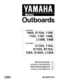
Руководство на английском, французском, немецком и испанском языках по техническому обслуживанию и ремонту подвесных лодочных моторов Yamaha моделей 100A/115B/115C/115F/115X/B115X/C115X/E115A/S115X/130B/130X/L130B/L130X/S130X/140B.
- Год издания: 1999
- Страниц: 737
- Формат: PDF
- Размер: 11,0 Mb
Руководство на английском языке по техническому обслуживанию и ремонту подвесных лодочных моторов Yamaha моделей F100B и F100C.
- Год издания: 2001
- Страниц: 345
- Формат: PDF
- Размер: 15,9 Mb
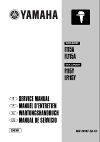
Руководство на английском, французском, немецком и испанском языках по техническому обслуживанию и ремонту подвесных лодочных моторов Yamaha моделей F115A, F115Y, FL115A и FL115Y.
- Год издания: 2000
- Страниц: 713
- Формат: PDF
- Размер: 13,5 Mb
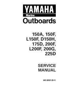
Руководство на английском языке по техническому обслуживанию и ремонту подвесных лодочных моторов Yamaha моделей 150A/150F/D150H/L150F/175D/200F/200G/L200F/225D.
- Год издания: 1998
- Страниц: 368
- Формат: PDF
- Размер: 8,7 Mb
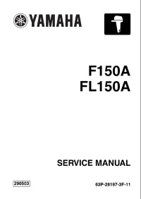
Руководство на английском языке по техническому обслуживанию и ремонту подвесных лодочных моторов Yamaha моделей F150A и FL150A.
- Год издания: 2003
- Страниц: 313
- Формат: PDF
- Размер: 16,2 Mb
Руководство на английском языке по техническому обслуживанию и ремонту подвесных лодочных моторов Yamaha моделей 200A и L200A.
- Год издания: 2002
- Страниц: 281
- Формат: PDF
- Размер: 8,1 Mb
Руководство на английском языке по техническому обслуживанию и ремонту подвесных лодочных моторов Yamaha моделей L200C, LF200C, F225C и LF225C.
- Год издания: 2003
- Страниц: 323
- Формат: PDF
- Размер: 11,8 Mb
Руководство на английском языке по техническому обслуживанию и ремонту подвесных лодочных моторов Yamaha моделей LZ200N, LZ200Y, Z200N и Z200Y.
- Год издания: 1999
- Страниц: 392
- Формат: PDF
- Размер: 12,1 Mb
Руководство на английском языке по техническому обслуживанию и ремонту подвесных лодочных моторов Yamaha моделей 225G, 250B и L250B.
- Год издания: 1998
- Страниц: 367
- Формат: PDF
- Размер: 10,2 Mb
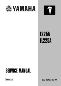
Руководство на английском языке по техническому обслуживанию и ремонту подвесных лодочных моторов Yamaha моделей F225A и FL225A.
- Год издания: 2001
- Страниц: 370
- Формат: PDF
- Размер: 21,7 Mb
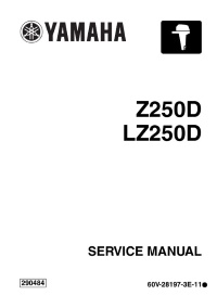
Сборник руководств на английском языке по техническому обслуживанию и ремонту подвесных лодочных моторов Yamaha моделей LZ250D, Z250D, LZ300A и Z300A.
- Год издания: 2002-2003
- Страниц: 388/90
- Формат: PDF
- Размер: 51,6 Mb
Руководство на английском языке по такелажу для подвесных лодочных моторов Yamaha.
- Год издания: 2007
- Страниц: 222
- Формат: PDF
- Размер: 9,3 Mb
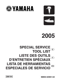
Перечень на английском, французском и испанском языках инструмента применяемого для технического обслуживания и ремонта гидроциклов и подвесных лодочных моторов Yamaha.
- Год издания: 2004
- Страниц: 86
- Формат: PDF
- Размер: 6,5 Mb


Руководство по ремонту лодочных моторов Yamaha 30AMH.
Руководство по ремонту лодочных моторов Yamaha 30AMH.
25B-30H.pdf
Adobe Acrobat Document
9.1 MB
Руководство по ремонту лодочных моторов Yamaha 9.9 FMH
Руководство по ремонту лодочных моторов Yamaha 9.9 FMH
9.9FMH_15FMH_63V_28197_Z6_11.pdf
Adobe Acrobat Document
7.7 MB
Руководство по ремонту лодочных моторов Yamaha 40VEO
40VEO_63B_28197_Z7_11.pdf
Adobe Acrobat Document
5.5 MB
Руководство по ремонту лодочных моторов Yamaha 60FET-90AETO
60FET_ETO_90AETO_6H2_28197_Z9_11.pdf
Adobe Acrobat Document
7.1 MB
Руководство по ремонту лодочных моторов Yamaha 130BETO
130BETO_6E5_28197_Z9_L1.pdf
Adobe Acrobat Document
11.0 MB
Руководство по ремонту лодочных моторов Yamaha 150 — 225
Yamaha 150-175-200-225 service.pdf
Adobe Acrobat Document
8.7 MB
РУКОВОДСТВО ПО ВЫБОРУ, МОНТАЖУ И УСТАНОВКЕ АКСЕССУАРОВ ДЛЯ ПОДВЕСНЫХ ЛОДОЧНЫХ МОТОРОВ YAMAHA
Rigging Guide_2010_rus.pdf
Adobe Acrobat Document
26.2 MB
Эл.схема лодочных моторов Yamaha 50G_60F_70B_75C_90A.pdf
.схема Yamaha 50G_60F_70B_75C_90A.pdf
Adobe Acrobat Document
658.5 KB
Эл.схема лодочного мотора Yamaha F115.pdf
.СХЕМА F115.pdf
Adobe Acrobat Document
113.7 KB
Руководство по эксплуатации Yamaha E115A
Adobe Acrobat Document
3.5 MB
Руководство по эксплуатации Yamaha F40 — F200
Yamaha F40-F200.pdf
Adobe Acrobat Document
4.6 MB
F4AMH_67D_28197_Z8_C1.pdf
Adobe Acrobat Document
6.4 MB
Эти обозначения применимы и к большинству других моторов

Ниже приведены диапазоны оптимальных оборотов
подвесных моторов при полностью открытой дроссельной заслонке и максимальной загрузке судна. Обороты двигателя при движении судна и верно подобранном гребном винте должны быть в пределах верхней
половины указанного диапазо-на.
Выбирайте винты, соответствующие этим
требованиям.
|
2-ТАКТНЫЕ ПОДВЕСНЫЕ МОТОРЫ |
|||
|
Модель |
Обороты мотора, об/мин |
||
|
2C |
4000–5000 |
||
|
3A |
4500–5500 |
||
|
4AC, 5C, 5CS |
4500–5500 |
||
|
6C |
4000–5000 |
||
|
8C |
4500–5500 |
||
|
E8D, EK8D |
4500–5500 |
||
|
9.9F, 15F, E9.9D, E15D, EK9.9D, EK15D, EK9.9J, |
4500–5500 |
||
|
20D, 25N |
5000–6000 |
||
|
30D |
4500–5500 |
||
|
E25B, 25B, E30H, 30H, 25X, EK25B, EK25C |
4500–5500 |
||
|
EK40G, E40G, EK40J, E40J |
4500–5500 |
||
|
E40X, 40X |
4500–5500 |
||
|
40V, 50H, 40Y |
4500–5500 |
||
|
E48C, E55C, 55B |
4500–5500 |
||
|
E60H, 60F |
4500–5500 |
||
|
70B |
5000–6000 |
||
|
55D, E60J, E65A, 75A, E75B, 75C, 85A, 90A |
4500–5500 |
||
|
E115A, 115B, 115C, 140B |
4500–5500 |
||
|
130B |
5000–6000 |
||
|
150A, 200A |
4500–5500 |
||
|
150F, 150G, 175D, 200F |
4500–5500 |
||
|
Z150P, Z175G, Z200N, Z150Q, Z175H, Z200P |
4500–5500 |
||
|
200G, 225D |
5000–6000 |
||
|
250G |
4500–5500 |
||
|
Z200R, Z225H, Z250F |
5000–6000 |
||
|
Z300B |
4500–6000 |
||
0*Модели моторов с левым направлением вращения гребного винта
имеют те же оптимальные обороты, что и моторы с пра-вым направлением вращения.
|
4-ТАКТНЫЕ ПОДВЕСНЫЕ МОТОРЫ |
|||
|
Модель |
Обороты мотора, об/мин |
||
|
F2A, F2.5A |
5250–5750 |
||
|
F4A |
4000–5000 |
||
|
F6A |
4500–5500 |
||
|
F8C, F9.9F, FT9.9G |
5000–6000 |
||
|
F9.9H, F15C, F20B, F20C |
5000–6000 |
||
|
F25D, FT25F |
5000–6000 |
||
|
F30B, F40F |
5000–6000 |
||
|
FT50C, F50D |
5000–6000 |
||
|
F40D, F50F, FT50G, F60C, FT60D |
5000–6000 |
||
|
F95A, F100B |
5000–6000 |
||
|
F75B, F75C, F80B, F80C, F90B, F100D |
5000–6000 |
||
|
F/FL115A |
5000–6000 |
||
|
F/FL150A, F/FL150B |
5000–6000 |
||
|
F/FL200A, F/FL200B, F/FL225A |
5000–6000 |
||
|
F/FL200C, F/FL225B, F225C, F/FL250A, |
5000–6000 |
||
|
F/FL300A, F/FL350A |
5000–6000 |
||
Если обороты двигателя превышают
рекомендуемые, замените гребной винт на модель с большим шагом.
Если обороты двигателя ниже рекомендуемых, замените гребной винт
на модель с меньшим шагом.
ПРИМЕЧАНИЕ
Не допускайте продолжительной работы
двигателя на оборотах, превышающих рекомендуе-мые – это может привести к повреждению двигателя.
0*Изменение
шага гребного винта на 25 мм приведет к изменению оборотов двигателя на 200 об/ мин.
Кроме того, изменение оборотов зависит от типа
винта, воды (соленой/пресной), типа судна (мас-сы и формы корпуса) и т. д.
0*При подъеме мотора с помощью системы гидроподъема
максимальные обороты двигателя увели-чатся.
- Manuals
- Brands
- Yamaha Manuals
- Outboard Motor
- F80BETL
- Service manual
-
Contents
-
Table of Contents
-
Troubleshooting
-
Bookmarks
Related Manuals for Yamaha F80BETL
Summary of Contents for Yamaha F80BETL
-
Page 1
F80B F100D SERVICE MANUAL 6D9-28197-3G-11… -
Page 2
NOTICE This manual has been prepared by Yamaha primarily for use by Yamaha dealers and their trained mechanics when performing maintenance procedures and repairs to Yamaha equipment. It has been written to suit the needs of persons who have a basic understanding of the mechanical and electrical concepts and procedures inherent in the work, for without such knowledge attempted repairs or service to the equipment could render it unsafe or unfit for use. -
Page 3
Contents General information INFO Specifications SPEC Periodic checks and adjustments Fuel system FUEL Power unit POWR Lower unit LOWR Bracket unit BRKT – Electrical systems ELEC Troubleshooting TRBL SHTG Index… -
Page 5: Table Of Contents
INFO General information How to use this manual …………….. 1-1 Manual format……………….. 1-1 Symbols………………… 1-2 Safety while working………………1-3 Fire prevention………………. 1-3 Ventilation………………..1-3 Self-protection ………………. 1-3 Parts, lubricants, and sealants …………..1-3 Good working practices …………….1-4 Disassembly and assembly …………… 1-4 Identification………………..1-5 Applicable model ………………1-5 Serial number ………………..
-
Page 6: How To Use This Manual
INFO General information How to use this manual Manual format The format of this manual has been designed to make service procedures clear and easy to under- stand. Use the information below as a guide for effective and quality service. 1 Parts are shown and detailed in an exploded diagram and are listed in the components list.
-
Page 7: Symbols
7 Apply Yamaha 4-stroke motor oil A Apply corrosion resistant grease 8 Apply gear oil (Yamaha grease D) 9 Apply water resistant grease (Yamaha grease A) B Apply low temperature resistant grease 0 Apply molybdenum disulfide grease (Yamaha grease C)
-
Page 8: Safety While Working
Parts, lubricants, and sealants Use only genuine Yamaha parts, lubricants, and sealants or those recommended by Yamaha, when servicing or repairing the out- board motor. Ventilation Gasoline vapor and exhaust gas are heavier than air and extremely poisonous.
-
Page 9: Good Working Practices
Safety while working 6. Keep a supply of clean, lint-free cloths for Disassembly and assembly wiping up spills, etc. 1. Use compressed air to remove dust and dirt during disassembly. Good working practices Special service tools 2. Apply engine oil to the contact surfaces Use the recommended special service tools of moving parts before assembly.
-
Page 10: Identification
INFO General information Identification Propeller selection Applicable model The performance of a boat and outboard motor will be critically affected by the size This manual covers the following model. and type of propeller you choose. Propellers Applicable model greatly affect boat speed, acceleration, engine life, fuel economy, and even boating F80BET, F100DET and steering capabilities.
-
Page 11: Selection
Identification / Propeller selection / Predelivery checks Selection When the engine speed is at the full throttle operating range (5,000–6,000 r/min), the ideal propeller for the boat is one that pro- vides maximum performance in relation to boat speed and fuel consumption. Propeller size (in) Material 12 5/8 ×…
-
Page 12: Checking The Gear Oil Level
INFO General information Checking the gear oil level NOTE: 1. Check the gear oil level. The optimum mounting height is affected by the combination of the boat and the outboard motor. To determine the optimum mounting height, test run the outboard motor at differ- ent heights.
-
Page 13: Checking The Steering System
Predelivery checks S69J3370 S69J1210 WARNING Checking the power trim and tilt system The shift/throttle cable joint must be screwed in a minimum of 8.0 mm (0.31 in) 1. Check that the outboard motor tilts up and down smoothly when operating the power trim and tilt unit.
-
Page 14: Checking The Cooling Water Pilot Hole
INFO General information 3. Check that the engine turns off when the Break-in engine stop lanyard is pulled from the During the test run, perform the break-in engine stop lanyard switch. operation in the following three stages. 1. One hour a at 2,000 r/min or at approxi- mately half throttle 2.
-
Page 15
SPEC Specifications General specifications………………. 2-1 Maintenance specification …………….2-3 Power unit………………..2-3 Lower unit ………………..2-6 Electrical ………………..2-6 Dimensions………………..2-9 Tightening torques………………2-11 Specified torques………………2-11 General torques………………2-13 6D93G11… -
Page 16: Specifications
SPEC Specifications General specifications Model Item Unit F80BET F100DET Dimension Overall length mm (in) 817 (32.2) Overall width mm (in) 479 (18.9) Overall height mm (in) 1,582 (62.3) mm (in) 1,710 (67.3) Boat transom height mm (in) 508 (20.0) mm (in) 635 (25.0) Weight (with aluminum propeller)
-
Page 17
General specifications Model Item Unit F80BET F100DET Fuel and oil Fuel type Regular unleaded gasoline (*1) Fuel minimum rating Engine oil 4-stroke motor oil Engine oil grade SE, SF, SG, SH, or SJ 10W-30 or 10W-40 Engine oil quantity (without oil filter replacement) L (US qt, 4.3 (4.55, 3.78) Imp qt) -
Page 18: Maintenance Specification
SPEC Specifications Maintenance specification Power unit Model Item Unit F80BET F100DET Power unit Minimum compression 860 (8.6, 124.7) (*1) pressure (kgf/cm , psi) (*2) Oil pressure 510 (5.1, 74.0) at engine idle speed (kgf/cm , psi) Cylinder head Warpage limit mm (in) 0.1 (0.0039) (lines indicate straightedge…
-
Page 19
Maintenance specification Model Item Unit F80BET F100DET Oil ring Dimension B mm (in) 2.38–2.48 (0.0937–0.0976) Dimension T mm (in) 2.40 (0.0945) End gap mm (in) 0.20–0.70 (0.0079–0.0276) Side clearance mm (in) 0.03–0.15 (0.0012–0.0059) Camshafts Intake (A) mm (in) 36.48–36.58 (1.4362–1.4402) Exhaust (A) mm (in) 36.90–37.06 (1.4528–1.4591) -
Page 20
SPEC Specifications Model Item Unit F80BET F100DET Valve lifters Valve lifter outside diameter mm (in) 27.965–27.980 (1.1010–1.1016) Valve lifter-to-cylinder head mm (in) 0.020–0.056 (0.0008–0.0022) clearance Valve shims Valve shim thickness mm (in) 2.0–3.3 (0.08–0.13) (in 0.025 mm increments) Connecting rods Big end inside diameter mm (in) 47.025–47.045 (1.8514–1.8522) -
Page 21: Lower Unit
Maintenance specification Model Item Unit F80BET F100DET Oil pump Discharge L (US gal, 5.9 (1.559, 1.298) at 1,000 r/min at 97–103 °C (207–217 °F) Imp gal)/min with 10W-30 engine oil Pressure 118.0 (1.18, 17.1) at 1,000 r/min at 97–103 °C (207–217 °F) (kgf/cm , psi) with 10W-30 engine oil…
-
Page 22
SPEC Specifications Model Item Unit F80BET F100DET ECM output peak voltage (B/R, B/W – Ground) at cranking (loaded) at 1,500 r/min (loaded) at 3,500 r/min (loaded) Pulser coil output peak voltage (W/R, W/B – B) at cranking (unloaded) at cranking (loaded) at 1,500 r/min (loaded) 18.2 at 3,500 r/min (loaded) -
Page 23
Maintenance specification Model Item Unit F80BET F100DET Charging system Fuse Stator coil output peak voltage (W – W) at cranking (unloaded) 12.4 at 1,500 r/min (unloaded) 45.3 at 3,500 r/min (unloaded) 98.3 Stator coil resistance (W – W) at 20 °C (68 °F) 0.24–0.36 Ω… -
Page 24: Dimensions
SPEC Specifications Dimensions Exterior mm (in) L : 998 (39.3) 527 (20.7) X: 1,115 (43.9) 171 (6.73) 651 (25.6) 62 (2.4) 164 (6.5) 12˚ 28 (1.1) 574 (22.6) S6D82010 6D93G11…
-
Page 25
Maintenance specification Clamp bracket mm (in) 180 (7.1) 180 (7.1) 163.5 (6.4) 163.5 (6.4) 80 (3.1) 13 (0.5) 13 (0.5) 125.4 (4.9) 125.4 (4.9) S6D82020 2-10 6D93G11… -
Page 26
SPEC Specifications Tightening torques Specified torques Tightening torques Part to be tightened Thread size N·m kgf·m ft·lb Fuel system Fuel filter cup — Fuel pump mounting bolt Fuel pump screw Sensor assembly screw 0.37 Idle speed control screw 0.37 Fuel rail mounting bolt Throttle body mounting bolt Fuel cooler screw Float chamber screw… -
Page 27
Tightening torques Tightening torques Part to be tightened Thread size N·m kgf·m ft·lb 10.3 20.7 Cylinder head bolt 11.1 22.1 90° Spark plug — 18.4 Cylinder block plug 17.0 Oil filter joint — 36.1 Oil filter — 13.3 Exhaust cover bolt Anode screw Exhaust cover plug 40.6… -
Page 28
SPEC Specifications Tightening torques Part to be tightened Thread size N·m kgf·m ft·lb Exhaust manifold bolt Steering arm stud bolt 14.8 Self-locking nut — 11.1 Trim sensor cam screw Power trim and tilt unit Reservoir cap — PTT motor bolt Gear pump bolt Gear pump housing bolt Relief valve cap bolt… -
Page 29
Periodic checks and adjustments Special service tools ………………3-1 Maintenance interval chart…………….3-2 Top cowling ………………..3-3 Checking the top cowling…………….3-3 Fuel system ………………..3-3 Checking the fuel joint and fuel hoses (fuel joint-to-fuel injector) ….3-3 Checking the fuel filter …………….3-3 Power unit………………….. -
Page 30: Special Service Tools
Periodic checks and adjustments Special service tools Digital tachometer 90890-06760 Leakage tester 90890-06840 Oil filter wrench 64 90890-01426 6D93G11…
-
Page 31: Maintenance Interval Chart
Special service tools / Maintenance interval chart Maintenance interval chart Use the following chart as a guideline for general maintenance. Adjust the maintenance intervals according to the operating conditions of the outboard motor. Initial Every Refer to Item Remarks 10 hours 50 hours 100 hours 200 hours…
-
Page 32: Top Cowling
Periodic checks and adjustments Top cowling 2. Check the low-pressure fuel hose con- nections and fuel joint for leaks. Replace Checking the top cowling if necessary. Also, check the fuel filter 1, 1. Check the fitting by pushing the cowling fuel pump 2, strainer 3, and fuel cooler with both hands.
-
Page 33: Power Unit
Top cowling / Fuel system / Power unit Power unit Checking the engine oil 1. Place the outboard motor in an upright position. 2. Remove the oil dipstick, wipe it clean, and then insert it back into the dipstick hole. 3.
-
Page 34: Replacing The Oil Filter
Periodic checks and adjustments 2. Remove the oil dipstick and oil filler cap 7. Turn the engine off, and then check the oil level and correct it if necessary. Replacing the oil filter 1. Extract the engine oil with an oil changer or drain it.
-
Page 35: Checking The Timing Belt
Power unit 2. While turning the flywheel magnet clock- wise, check the interior a and the exte- rior b of the timing belt for cracks, damage, or wear. Replace if necessary. S6D83070 NOTE: For replacement procedures, see Chapter 5, “Replacing the timing belt.” S6D83060 Oil filter: Checking the spark plugs…
-
Page 36: Checking The Thermostat
Periodic checks and adjustments 5. Check the spark plug gap a. Adjust if out of specification. Specified spark plug: LFR5A-11 (NGK) Spark plug gap a: 1.0–1.1 mm (0.039–0.043 in) S6D83080 6. Install the spark plugs, tighten them fin- 3. Suspend the thermostat in a container of ger tight, then to the specified torque water.
-
Page 37: Checking The Cooling Water Passage
Power unit / Control system Water Valve lift a temperature 0.05 mm 58–62 °C (0.0020 in) (136–144 °F) (valve begins to lift) above more than 70 °C (158 °F) 4.3 mm (0.17 in) 6. Install the thermostat and cover. Control system 7.
-
Page 38
Periodic checks and adjustments 3. Loosen the locknut 1, remove the clip 2, and then disconnect the throttle cable joint 3. 4. Loosen the locknut 4, and then discon- nect the throttle link rod joint 5 from the ball joint of the throttle body. S6D83110 8. -
Page 39: Checking The Gear Shift Operation
Control system 5. Align the alignment mark a on the bush- ing and alignment mark b on the bracket. S69J3370 WARNING The throttle cable joint must be screwed S6D81040 in a minimum of 8.0 mm (0.31 in) c. 6. Install the clip 4. 12.
-
Page 40: Bracket Unit
Periodic checks and adjustments Bracket unit Checking the power trim and tilt operation 1. Fully tilt the outboard motor up and down a few times and check the entire trim and tilt range for smooth operation. Check the power trim and tilt fluid level if necessary. S6D83150 WARNING After tilting up the outboard motor, be…
-
Page 41: Lower Unit
Bracket unit / Lower unit Lower unit Checking the gear oil level 1. Fully tilt the outboard motor down. 2. Remove the check screw 1, and then check the gear oil level in the lower case. 3. Check the oil for metal and discoloration, S60C3540 and its viscosity.
-
Page 42: Checking The Lower Unit For Air Leakage
Periodic checks and adjustments 4. Insert a gear oil tube or gear oil pump into the drain hole and slowly fill the gear oil until oil flows out of the check hole and no air bubbles are visible. Leakage tester: 90890-06840 2.
-
Page 43: General
Lower unit / General General NOTE: Checking the anodes If it is necessary to disassemble the outboard 1. Check the anodes and trim tab for motor to check an anode, refer to the applica- scales, grease, or oil. Clean if necessary. ble disassembly procedure in this manual.
-
Page 44: Lubricating The Outboard Motor
Periodic checks and adjustments 2. Check the specific gravity of the electro- Lubricating the outboard motor lyte. Fully charge the battery if out of 1. Apply water resistant grease to the areas specification. shown. WARNING Battery electrolyte is dangerous; it con- tains sulfuric acid which is poisonous and highly caustic.
-
Page 45
General S60C3710 NOTE: Apply grease to the grease nipple until it flows from the bushings a. 2. Apply low temperature resistant grease to the area shown. S6D83190 3. Apply corrosion resistant grease to the area shown. 3-16 6D93G11… -
Page 46
Periodic checks and adjustments — MEMO — 3-17 6D93G11… -
Page 47
FUEL Fuel system Special service tools ………………4-1 Hose routing ………………..4-2 Fuel and blowby hoses…………….4-2 Fuel filter and fuel pump …………….4-3 Checking the fuel pump…………….4-5 Disassembling the fuel pump …………..4-5 Checking the diaphragm and valves …………4-6 Assembling the fuel pump …………….. 4-6 Intake manifold……………….. -
Page 48: Fuel System
FUEL Fuel system Special service tools Vacuum/pressure pump gauge set 90890-06756 Fuel pressure gauge 90890-06786 Fuel pressure gauge adapter B 90890-06942 6D93G11…
-
Page 49: Hose Routing
Special service tools / Hose routing Hose routing Fuel and blowby hoses 1 Blowby hose 2 Fuel hose (primary pump-to-fuel filter) 3 Fuel hose (fuel filter-to-fuel pump) 4 Fuel hose (fuel pump-to-strainer) 5 Fuel hose (strainer-to-vapor separator) 6 High-pressure fuel hose (vapor separator-to-fuel rail) 7 Fuel hose (pressure regulator-to-fuel cooler) 8 Fuel hose (fuel cooler-to-vapor separator) 9 Canister hose (vapor separator-to-canister)
-
Page 50: Fuel Filter And Fuel Pump
FUEL Fuel system Fuel filter and fuel pump · · · 10 N m (1.0 kgf m, 7.4 ft · · · m (0.3 kgf m, 2.2 ft S6D84020 Part name Q’ty Remarks Fuel filter assembly O-ring Not reusable Fuel filter element O-ring Not reusable Float…
-
Page 51
Fuel filter and fuel pump · · · m (0.4 kgf m, 3.0 ft S6D84030 Part name Q’ty Remarks Screw ø6 × 35 mm Cover Gasket Not reusable Fuel pump body 2 assembly Diaphragm Spring Fuel pump body 1 Spring Plunger 6D93G11… -
Page 52: Checking The Fuel Pump
FUEL Fuel system Checking the fuel pump 6. Apply the specified positive pressure and check that there is no air leakage. Disas- 1. Place a drain pan under the fuel hose semble the fuel pump if necessary. connections, and then disconnect the fuel hoses from the fuel pump.
-
Page 53: Checking The Diaphragm And Valves
Fuel filter and fuel pump 3. Slowly let up on the plunger and dia- phragm, and then remove them. Checking the diaphragm and valves 1. Check the diaphragm for tears and the valves for cracks. Replace if necessary. Assembling the fuel pump NOTE: Clean the parts and soak the valves and the diaphragm in gasoline before assembly to…
-
Page 54: Intake Manifold
FUEL Fuel system Intake manifold S6D94010 Part name Q’ty Remarks Intake silencer F80BET Bolt M6 × 80 mm Bushing Collar Intake manifold assembly Bolt M8 × 30 mm Collar Bolt M8 × 100 mm Spacer Bolt M6 × 45 mm Collar Holder Gasket…
-
Page 55
Intake manifold · · · 3.7 N m (0.37 kgf m, 2.7 ft · · · m (0.8 kgf m, 5.9 ft · · · m (0.8 kgf m, 5.9 ft S6D84050 Part name Q’ty Remarks Intake manifold Sensor assembly Screw ø5 ×… -
Page 56: Checking The Throttle Position Sensor
• If the throttle position sensor output voltage is out of specification, reinstall the throttle position sensor. • Measure the throttle position sensor output voltage using the Yamaha Diagnostic Sys- tem. • Do not turn the throttle stop screw a. Throttle position sensor output voltage at engine idle speed: 0.8–1.2 V…
-
Page 57
Intake manifold / Vapor separator Vapor separator S6D84070 Part name Q’ty Remarks Vapor separator Bolt M6 × 30 mm Grommet Collar Fuel hose Fuel inlet hose Hose Joint Hose Hose Hose Hose Clamp Clamp Quick connector Clamp Not reusable Plastic tie Not reusable 4-10 6D93G11… -
Page 58
FUEL Fuel system · · · m (0.3 kgf m, 2.2 ft · · · 1.5 N m (0.15 kgf m, 1.1 ft · · · m (0.3 kgf m, 2.2 ft · · · m (0.4 kgf m, 3.0 ft S6D84080 Part name Q’ty… -
Page 59: Vapor Separator
Vapor separator · · · m (0.5 kgf m, 3.7 ft · · · 10 N m (1.0 kgf m, 7.4 ft · · · m (0.2 kgf m, 1.5 ft · · · m (0.4 kgf m, 3.0 ft ·…
-
Page 60: Reducing The Fuel Pressure
FUEL Fuel system Reducing the fuel pressure CAUTION: 1. Remove the cap 1. • Do not rotate the quick connector tab 1 2. Cover the pressure check valve a of the past the stopper position a, otherwise it vapor separator with a rag, and then could be damaged.
-
Page 61: Checking The Pressure Regulator
Vapor separator Fuel pressure (reference data): 230 kPa (2.3 kgf/cm , 33.4 psi) WARNING • Before measuring the fuel pressure, make sure that the drain screw is tight- ened securely. • Do not loosen the drain screw while S6D84190 measuring the fuel pressure. Loosening WARNING the drain screw can cause fuel to spray out creating a fire hazard.
-
Page 62: Draining The Fuel
FUEL Fuel system 4. Disconnect the pressure regulator hose, WARNING and then connect the special service tools to the pressure regulator. • Before measuring the fuel pressure, make sure that the drain screw is tight- ened securely. • Do not loosen the drain screw while measuring the fuel pressure.
-
Page 63: Removing The Fuel Hose Clamp
Vapor separator S6D84100 WARNING WARNING Reduce the fuel pressure before loosen- Do not reuse the fuel hose clamp, always ing the vapor separator drain screw, or replace it with a new one. pressurized fuel will spray out and may result in serious injury. Disassembling the vapor separator 1.
-
Page 64: Assembling The Vapor Separator
FUEL Fuel system 2. Check the float for deterioration. Replace if necessary. 3. Check the filter for dirt or residue. Clean if necessary. Assembling the vapor separator 1. Install the needle valve, float, and float pin, and then check the float for smooth S6C14200 operation.
-
Page 65
Vapor separator Float height d: 35.0 ± 1.0 mm (1.38 ± 0.04 in) NOTE: When adjusting the float height, do not bend the lever e. 4-18 6D93G11… -
Page 66: Canister
FUEL Fuel system Canister S6D84150 Part name Q’ty Remarks Bolt M6 × 16 mm Bracket Canister Bolt M6 × 28 mm Grommet Bracket Collar Hose Hose Hose Filter Hose Clamp Bolt M6 × 10 mm Holder Bolt M6 × 16 mm Bracket 4-19 6D93G11…
-
Page 67: Checking The Canister
Canister Checking the canister 1. Check the canister for cracks. Replace if necessary. 2. Connect the special service tool to the atmospheric port 1 and cover the other ports, each with a finger. S6D84160 3. Apply the specified positive pressure and check that there is no air leakage.
-
Page 68
POWR Power unit Special service tools ………………5-1 Power unit………………….. 5-3 Checking the compression pressure …………5-3 Checking the oil pressure …………….5-3 Checking the valve clearance…………..5-10 Replacing the timing belt ……………..5-13 Removing the power unit……………..5-16 Removing the timing belt and sprockets……….5-17 Checking the timing belt and sprockets………..5-18 Installing the sprockets and timing belt…………5-18 Throttle link……………….. -
Page 69
Cylinder block ………………..5-40 Disassembling the cylinder block …………5-41 Checking the piston diameter …………..5-41 Checking the cylinder bore …………..5-42 Checking the piston clearance …………..5-42 Checking the piston rings …………….5-42 Checking the piston ring grooves …………5-43 Checking the piston ring side clearance……….5-43 Checking the connecting rod big end side clearance ……5-43 Checking the crankshaft …………….5-44 Checking the crankpin oil clearance………… -
Page 70
POWR Power unit Special service tools Compression gauge Valve spring compressor 90890-03160 90890-04019 Compression gauge extension M14 Valve spring compressor attachment 90890-06563 90890-06320 Flywheel holder Valve guide remover/installer 5.9 90890-06522 90890-04064 Flywheel puller Valve guide reamer 6.0 90890-06521 90890-04066 Crankshaft holder 20 Valve seat cutter holder 90890-06552 90890-06553… -
Page 71: Special Service Tools
Special service tools Valve seat cutter 90890-06312, 90890-06315, 90890-06324, 90890-06326, 90890-06328, 90890-06555 Piston slider 90890-06530 Oil filter wrench 64 90890-01426 6D93G11…
-
Page 72: Power Unit
POWR Power unit Power unit NOTE: Checking the compression pressure • If the compression pressure increases, 1. Start the engine, warm it up for 5 min- check the pistons and piston rings for wear. utes, and then turn it off. Replace if necessary.
-
Page 73
Power unit · · · 42 N m (4.2 kgf m, 31.0 ft · · · 42 N m (4.2 kgf m, 31.0 ft · · · m (0.4 kgf m, 3.0 ft S6D85010 Part name Q’ty Remarks Damper Grommet Grommet Flywheel magnet cover Power unit… -
Page 74
POWR Power unit · · · 215 N m (21.5 kgf m, 158.6 ft S6D85020 Part name Q’ty Remarks Washer Flywheel magnet Screw ø4 × 10 mm Screw ø6 × 30 mm Stator coil Bolt M6 × 30 mm Stator assembly Collar Bolt M6 ×… -
Page 75
Power unit · · · 265 N m (26.5 kgf m, 195.5 ft · · · 60 N m (6.0 kgf m, 44.3 ft · · · 39 N m (3.9 kgf m, 28.8 ft S6D85030 Part name Q’ty Remarks Timing belt Bolt M10 ×… -
Page 76
POWR Power unit · · · 29 N m (2.9 kgf m, 21.4 ft · · · m (0.2 kgf m, 1.5 ft · · · m (0.4 kgf m, 3.0 ft · · · m (0.8 kgf m, 5.9 ft ·… -
Page 77
Power unit · · · 29 N m (2.9 kgf m, 21.4 ft · · · m (0.2 kgf m, 1.5 ft · · · m (0.4 kgf m, 3.0 ft · · · m (0.8 kgf m, 5.9 ft ·… -
Page 78
POWR Power unit m (0.8 kgf m, 5.9 ft • • • S1280B 17 N m (1.7 kgf m, 12.5 ft • • • · · · m (0.2 kgf m, 1.5 ft S1280B m (0.8 kgf m, 5.9 ft •… -
Page 79: Checking The Valve Clearance
Power unit Checking the valve clearance CAUTION: • Do not turn the flywheel magnet coun- terclockwise, otherwise the valve sys- tem may be damaged. • Do not remove the ignition timing pointer. • Do not turn the flywheel magnet or the driven sprockets when the timing belt is not installed.
-
Page 80
POWR Power unit 4. Install the driven sprockets 0, timing belt Valve clearance (cold): 9, and spring 8, and then tighten the Intake e: tensioner bolt. 0.20 ± 0.03 mm (0.008 ± 0.001 in) Exhaust f: 0.34 ± 0.03 mm (0.013 ± 0.001 in) 6. -
Page 81
Power unit 19. Check that the “TDC” mark a on the fly- 11. Remove the valve shim C from the valve lifter D using a thin screwdriver. wheel magnet is aligned with the pointer b, and that “ ” marks c and d on the driven sprockets are aligned. -
Page 82: Replacing The Timing Belt
POWR Power unit Replacing the timing belt CAUTION: • Do not turn the drive sprocket counter- clockwise, otherwise the valve system may be damaged. • Do not remove the ignition timing pointer. • Do not turn the drive sprocket or the driven sprockets when the timing belt is not installed.
-
Page 83
Power unit 9. Check that “ ” marks c and d on the driven sprockets are aligned. S6D85220 6. Disconnect the cooling water hose 3 S6D85240 and remove the bracket 4. 7. Remove the spring 5 and timing belt tensioner 6, and then remove the timing belt 7 from the driven sprockets, then from the drive sprocket. -
Page 84
POWR Power unit 10. Install a new timing belt 8 onto the drive 13. Install the spring A. sprocket with its part number in the upright position, and then install the belt onto the driven sprockets in a counter- clockwise direction. S6D85260 14. -
Page 85: Removing The Power Unit
Power unit 18. Install the stator assembly and Woodruff 5. Disconnect the fuel hose and shift posi- key. tion switch coupler. 19. Install the flywheel magnet. 6. Disconnect the cooling water pilot hose, canister hose, and flushing hose. 7. Remove the oil dipstick. 8.
-
Page 86: Removing The Timing Belt And Sprockets
POWR Power unit Removing the timing belt and NOTE: sprockets • Use a deep socket 2 for this procedure. • Do not turn the camshaft when loosening CAUTION: the drive sprocket nut. • Do not turn the drive sprocket counter- clockwise, otherwise the valve system may be damaged.
-
Page 87: Checking The Timing Belt And Sprockets
Power unit S6D85740 NOTE: • Apply engine oil to the driven sprocket bolts before installation. • Do not turn the camshafts when tightening the driven sprocket bolts. S6D85380 Flywheel holder: 90890-06522 Checking the timing belt and sprockets Driven sprocket bolt 2: 1.
-
Page 88
POWR Power unit 3. Install the retaining plate 3, Woodruff 6. Tighten the drive sprocket nut 6 to the key 4, drive sprocket 5, and nut 6, and specified torque. then tighten the nut. S6D85410 NOTE: Use a deep socket 7 for this procedure. Crankshaft holder 20 8: 90890-06552 Drive sprocket nut 6:… -
Page 89: Throttle Link
Power unit / Throttle link Throttle link S6D84140 Part name Q’ty Remarks Throttle cam Bolt M6 × 35 mm Collar Wave washer Washer Spring Washer Throttle lever Bolt M6 × 25 mm Collar Throttle link rod Throttle link rod joint Bracket Bolt M6 ×…
-
Page 90: Ecm
POWR Power unit S6D85050 Part name Q’ty Remarks Wiring harness Bracket Bolt M6 × 15 mm Bolt M6 × 12 mm Bracket Bracket Bracket Bolt M6 × 20 mm Collar Grommet Bolt M6 × 30 mm Rectifier Regulator Bolt M6 × 25 mm Bolt M6 ×…
-
Page 91: Junction Box
ECM / Junction box Junction box · · · m (0.3 kgf m, 2.2 ft · · · m (0.4 kgf m, 3.0 ft · · · m (0.3 kgf m, 2.2 ft · · · m (0.4 kgf m, 3.0 ft ·…
-
Page 92
POWR Power unit · · · m (0.3 kgf m, 2.2 ft · · · m (0.4 kgf m, 3.0 ft · · · m (0.3 kgf m, 2.2 ft · · · m (0.4 kgf m, 3.0 ft · ·… -
Page 93: Cylinder Head
Junction box / Cylinder head Cylinder head 15 N m (1.5 kgf m, 11.1 ft • • • 30 N m (3.0 kgf m, 22.1 ft • • • 90˚ 25 N m (2.5 kgf m, 18.4 ft • • •…
-
Page 94
POWR Power unit 15 N m (1.5 kgf m, 11.1 ft • • • 30 N m (3.0 kgf m, 22.1 ft • • • 90˚ 25 N m (2.5 kgf m, 18.4 ft • • • · · · 14 N m (1.4 kgf m, 10.3 ft… -
Page 95: Removing The Cylinder Head
Cylinder head Removing the cylinder head NOTE: 1. Remove the cylinder head cover. Do not mix the valve train parts. Keep them organized in their proper groups. 2. Remove camshaft caps 1 and 2 in the sequence shown. 5. Remove the cylinder head bolts in the sequence shown.
-
Page 96: Checking The Valve Lifters
POWR Power unit 6. Remove the intake and exhaust valves. Valve spring free length a: 53.20 mm (2.0945 in) 2. Measure the valve spring tilt b. Replace if above specification. Valve spring tilt limit b: 2.6 mm (0.10 in) NOTE: Checking the valves Be sure to keep the valves, springs, and 1.
-
Page 97: Checking The Valve Guides
Cylinder head S60C5450 Valve stem diameter b: Valve guide inside diameter a: Intake: Intake and exhaust: 5.975–5.990 mm 6.000–6.018 mm (0.2352–0.2358 in) (0.2362–0.2369 in) Exhaust: 5.960–5.975 mm 2. Calculate the valve stem-to-valve guide (0.2346–0.2352 in) clearance as follows. Replace the valve guide if out of specification.
-
Page 98: Checking The Valve Seat
POWR Power unit 2. Install the new valve guide 2 by striking 4. Measure the valve guide inside diameter. the special tool from the camshaft side to Valve guide inside diameter: the specified position a. Intake and exhaust: 6.000–6.018 mm (0.2362–0.2369 in) Checking the valve seat 1.
-
Page 99: Refacing The Valve Seat
Cylinder head S63P5240 Valve seat contact width a: 1.20–1.60 mm (0.0472–0.0630 in) Refacing the valve seat 1. Reface the valve seat with the valve seat a Slag or rough surface cutters. CAUTION: Do not over cut the valve seat. Be sure to turn the cutter evenly downward at a pres- sure of 40–50 N (4–5 kgf, 8.8–11 lbf) to prevent chatter marks.
-
Page 100
POWR Power unit 4. Use a 60° cutter to adjust the contact 7. If the valve seat contact area is too nar- width of the bottom edge of the valve row and situated near the top edge of the seat. valve face, use a 30°… -
Page 101: Checking The Camshafts
Cylinder head CAUTION: Do not get the lapping compound on the valve stem and valve guide. 10. After every lapping procedure, be sure to clean off any remaining lapping com- pound from the cylinder head and the valve. S6D85450 11. Check the valve seat contact area of the Camshaft runout limit: valve again.
-
Page 102: Installing The Valves
POWR Power unit 2. Check the cylinder head warpage using a straightedge 1 and thickness gauge 2 in the directions shown. Replace if above specification. S6D85470 NOTE: The valve spring can be installed in any direction. S6D85460 Valve spring compressor 6: 90890-04019 Cylinder head warpage limit: Valve spring compressor attachment…
-
Page 103: Installing The Cylinder Head
Cylinder head 90˚ S6D85480 S60C5680 CAUTION: 4. Lightly tap the valve spring retainer with a plastic hammer to set the valve cotters Do not reuse the cylinder head gasket, securely. always replace it with a new one. NOTE: • Apply engine oil to the cylinder head bolts before installation.
-
Page 104
POWR Power unit 3. Install the valve shims and valve lifters. 6. Install the camshaft caps in their proper positions as shown with the stamped NOTE: numbers upside down. • Apply engine oil to the valve shims and valve lifters before installation. 7. -
Page 105
Cylinder head S1280B S6D85520 Cylinder head cover bolt: 1st: 8 N·m (0.8 kgf·m, 5.9 ft·lb) 2nd: 8 N·m (0.8 kgf·m, 5.9 ft·lb) 9. Install the sprockets and timing belt. NOTE: For sprocket and timing belt installation pro- cedures, see “Installing the sprockets and timing belt.”… -
Page 106: Exhaust Cover
POWR Power unit Exhaust cover · · · 49 N m (4.9 kgf m, 36.1 ft · · · 18 N m (1.8 kgf m, 13.3 ft 23 N m (2.3 kgf m, 17.0 ft • • • · · ·…
-
Page 107
Exhaust cover · · · 49 N m (4.9 kgf m, 36.1 ft · · · 18 N m (1.8 kgf m, 13.3 ft 23 N m (2.3 kgf m, 17.0 ft • • • · · · 55 N m (5.5 kgf m, 40.6 ft ·… -
Page 108: Removing The Exhaust Cover
POWR Power unit Removing the exhaust cover Installing the exhaust cover 1. Remove the exhaust cover bolts in the 1. Install a new gasket and the exhaust sequence shown. cover. 2. Install the bolts, and then tighten them to the specified torques in two stages and in the sequence shown.
-
Page 109: Cylinder Block
Exhaust cover / Cylinder block Cylinder block 19 N m (1.9 kgf m, 14.0 ft • • • 60˚ S518 · · · 14 N m (1.4 kgf m, 10.3 ft · · · 28 N m (2.8 kgf m, 20.7 ft 18 N m (1.8 kgf m, 13.3 ft…
-
Page 110: Disassembling The Cylinder Block
POWR Power unit Disassembling the cylinder block 1. Place a rag under the oil filter, and then remove the filter using the oil filter wrench. NOTE: Be sure to clean up any oil spills. Oil filter wrench 64: 90890-01426 NOTE: •…
-
Page 111: Checking The Cylinder Bore
Cylinder block Checking the cylinder bore Piston clearance: 1. Measure the cylinder bore (D –D ) at 0.070–0.080 mm measuring points a, b, and c, and in (0.0028–0.0031 in) direction d (D ), which is parallel to the crankshaft, and direction e (D Checking the piston rings ), which is at a right angle to the crankshaft.
-
Page 112: Checking The Piston Ring Grooves
POWR Power unit 3. Check the piston ring end gap d at the Piston ring groove: specified measuring point. Replace if out Top ring a: of specification. 1.23–1.25 mm (0.048–0.049 in) Second ring b: 1.52–1.54 mm (0.060–0.061 in) Oil ring c: 2.51–2.53 mm (0.099–0.100 in) Checking the piston ring side clearance…
-
Page 113: Checking The Crankshaft
Cylinder block Crankshaft journal diameter a: 47.985–48.000 mm (1.8892–1.8898 in) Crankpin diameter b: 43.982–44.000 mm (1.7316–1.7323 in) Crankpin width c: 21.00–21.07 mm (0.8268–0.8295 in) 2. Measure the crankshaft runout. Replace the crankshaft if above specification. Connecting rod big end side clearance a: 0.14–0.28 mm (0.0055–0.0110 in) Checking the crankshaft…
-
Page 114
POWR Power unit 2. Install the upper bearing into the con- necting rod 1 and the lower bearing into the connecting rod cap 2. S60C5960 S60C5A10 NOTE: Install the bearings in their original positions. NOTE: Make sure that the large, flat side a on the connecting rod faces towards the flywheel 3. -
Page 115: Selecting The Connecting Rod Bearing
Cylinder block 6. Remove the connecting rod cap and 3. Check the crankpin mark on the crank- shaft 1. measure the width of the compressed Plastigauge (PG-1) on each crankpin. Replace the connecting rod bearing if out of specification. (#1) (#2) (#3) Crankpin oil clearance:…
-
Page 116: Checking The Crankshaft Journal Oil Clearance
POWR Power unit 5. Select the suitable color b for the con- Checking the crankshaft journal oil necting rod bearing from the table below clearance according to the calculated values. 1. Clean the bearings, the crankshaft jour- nals, the bearing portions of the crank- case, and the cylinder block.
-
Page 117: Selecting The Main Bearing
Cylinder block 5. Install the remaining half of the bearings 8. Remove the crankcase, and then mea- into the crankcase. sure the width of the compressed Plasti- gauge (PG-1) each crankshaft 6. Install the crankcase onto the cylinder journal. Replace the main bearing if out block and apply engine oil onto the of specification.
-
Page 118
POWR Power unit 2. Check the crankshaft journal mark on the crankshaft 1 and the cylinder block mark on the cylinder block 2. (#1) (#2) (#3) (#4) (#5) S6D85720 Main bearing selection table (20 °C [68 °F]) S60C5A40 Cylinder block Bearing journal inside Bearing… -
Page 119: Assembling The Power Unit
Cylinder block Assembling the power unit NOTE: 1. Install the oil ring 1, second ring 2, and Install the bearings in their original positions. top ring 3 onto the pistons with the “T” marks a on the piston rings facing upward.
-
Page 120
POWR Power unit 6. Set the crankshaft 8 and oil seals 9 and NOTE: 0 into the cylinder block as shown. • Make sure that the large, flat side c of the connecting rod faces towards the flywheel magnet side of the crankshaft. •… -
Page 121: Installing The Power Unit
Cylinder block Installing the power unit 1. Clean the power unit mating surface, and install the dowels 1 and a new gasket 2. Install the power unit 3 by installing bolts 4 and 5, then tightening them to the specified torques in two stages and in the sequence shown.
-
Page 122
POWR Power unit 6. Connect the fuel hose and shift position switch coupler. 7. Connect the PTT motor leads and PTT switch coupler, and then install the junc- tion box cover. PTT motor lead bolt: 4 N·m (0.4 kgf·m, 3.0 ft·lb) 8. -
Page 123
LOWR Lower unit Special service tools ………………6-1 Lower unit ………………….. 6-4 Removing the lower unit …………….6-8 Removing the water pump and shift rod………… 6-9 Disassembling the oil seal housing …………6-9 Checking the water pump and shift rod ………….6-9 Propeller shaft housing …………….6-10 Removing the propeller shaft housing assembly…….. -
Page 124: Special Service Tools
LOWR Lower unit Special service tools Ring nut wrench 3 Bearing separator 90890-06511 90890-06534 Ring nut wrench extension Stopper guide stand 90890-06513 90890-06538 Bearing housing puller claw L Bearing puller assembly 90890-06502 90890-06535 Stopper guide plate Needle bearing attachment 90890-06501 90890-06607, 90890-06611, 90890-06612, 90890-06614 Center bolt…
-
Page 125
Special service tools Driver rod SS Drive shaft holder 5 90890-06604 90890-06519 Bearing depth plate Pinion nut holder 90890-06603 New: 90890-06715 Current: 90890-06505 Driver rod LS 90890-06606 Bearing outer race puller assembly 90890-06523 Ball bearing attachment 90890-06655 Driver rod SL 90890-06602 Bearing inner race attachment 90890-06639, 90890-06643, 90890-06661… -
Page 126
LOWR Lower unit Driver rod LL Backlash indicator 90890-06605 90890-06706 Shift rod push arm Magnet base plate 90890-06052 90890-07003 Pinion height gauge Dial gauge set 90890-06710 90890-01252 Digital caliper Magnetic base B 90890-06704 90890-06844 Shimming plate 90890-06701 6D93G11… -
Page 127: Lower Unit
Special service tools / Lower unit Lower unit Part name Q’ty Remarks Lower unit Hose Check screw Gasket Not reusable Dowel Bolt M10 × 40 mm/L-transom model Drain screw Grommet Bolt M10 × 45 mm Bolt M8 × 60 mm/L-transom model Spacer Propeller Washer…
-
Page 128
LOWR Lower unit Part name Q’ty Remarks Dowel X-transom model Extension X-transom model Stud bolt M10 × 180 mm/X-transom model Washer X-transom model Spring washer X-transom model X-transom model Bolt M8 × 190 mm/X-transom model 6D93G11… -
Page 129
Lower unit Part name Q’ty Remarks Bolt M6 × 16 mm O-ring Not reusable Oil seal Not reusable Oil seal housing O-ring Not reusable Circlip Shift rod Woodruff key Screw ø4 × 12 mm Bolt M8 × 75 mm Cover Bolt M8 ×… -
Page 130
LOWR Lower unit Part name Q’ty Remarks Gasket Not reusable Outer plate cartridge Gasket Not reusable Oil seal housing O-ring Not reusable Gasket Not reusable Oil seal Not reusable 6D93G11… -
Page 131: Removing The Lower Unit
Lower unit Removing the lower unit 1. Drain the gear oil. 2. Set the gear shift to the neutral position, S6D86020 and place a block of wood between the 5. Loosen the bolts (nuts), and then remove anti-cavitation plate and propeller to keep the lower unit from the upper case.
-
Page 132: Removing The Water Pump And Shift Rod
LOWR Lower unit Removing the water pump and shift Checking the water pump and shift 1. Remove the water pump housing and 1. Check the water pump housing for defor- impeller. mation. Replace if necessary. 2. Remove the Woodruff key. 2.
-
Page 133: Propeller Shaft Housing
Lower unit / Propeller shaft housing Propeller shaft housing Part name Q’ty Remarks Slider Shift plunger Cross pin Dog clutch Spring Propeller shaft Washer Reverse gear Thrust washer Ball bearing Not reusable O-ring Not reusable Propeller shaft housing Straight key Needle bearing Oil seal Not reusable…
-
Page 134: Removing The Propeller Shaft Housing Assembly
LOWR Lower unit Removing the propeller shaft Disassembling the propeller shaft housing assembly assembly 1. Straighten the claw washer tabs a, and 1. Remove the spring 1, and then remove then remove the ring nut and claw the cross pin 2, dog clutch 3, slider and washer.
-
Page 135: Checking The Propeller Shaft Housing
Propeller shaft housing CAUTION: Do not reuse the bearing, always replace it with a new one. Stopper guide plate 5: 90890-06501 Stopper guide stand 6: 90890-06538 Bearing puller assembly 7: S6D56510 90890-06535 Runout limit: 0.02 mm (0.0008 in) 3. Remove the oil seals and needle bear- ing.
-
Page 136: Assembling The Propeller Shaft Housing
LOWR Lower unit Assembling the propeller shaft Ball bearing attachment 4: housing 90890-06655 1. Install the needle bearing into the propel- Driver rod LS 5: 90890-06606 ler shaft housing to the specified depth. Depth d: 5.0 ± 0.5 mm (0.20 ± 0.02 in) 3.
-
Page 137
Propeller shaft housing Bearing inner race attachment 0: 90890-06661 6-14 6D93G11… -
Page 138: Drive Shaft And Lower Case
LOWR Lower unit Drive shaft and lower case Part name Q’ty Remarks Drive shaft Taper roller bearing Not reusable Pinion shim — Sleeve Hose Plastic tie Not reusable Joint Cooling water inlet cover Screw ø5 × 40 mm Seal Plate Forward gear shim —…
-
Page 139
Drive shaft and lower case Part name Q’ty Remarks Pinion Lower case 6-16 6D93G11… -
Page 140: Removing The Drive Shaft
LOWR Lower unit Removing the drive shaft 1. Remove the drive shaft assembly and pinion, and then pull out the forward gear. CAUTION: Do not reuse the bearing, always replace it with a new one. S68S6360J Drive shaft holder 5 1: 90890-06519 Pinion nut holder 2: Bearing separator 1: 90890-06534 New: 90890-06715…
-
Page 141: Checking The Pinion And Forward Gear
Drive shaft and lower case Checking the pinion and forward NOTE: gear Install the claws as shown. 1. Check the teeth of the pinion, and the teeth and dogs of the forward gear for cracks or wear. Replace if necessary. Bearing outer race puller assembly 1: Checking the bearings…
-
Page 142: Assembling The Lower Case
LOWR Lower unit Assembling the lower case CAUTION: 1. Install the needle bearing into the lower Add or remove shim(s), if necessary, if case to the specified depth. replacing the taper roller bearing or lower case. NOTE: • Apply the gear oil to the inside and outside of the sleeve before installation.
-
Page 143: Assembling The Drive Shaft
Drive shaft and lower case Bearing inner race attachment 1: 90890-06643 Installing the drive shaft 1. Install the forward gear, then the drive shaft assembly, pinion, and pinion nut, and then tighten the nut to the specified torque. Needle bearing attachment 1: 90890-06607 2.
-
Page 144: Installing The Water Pump And Shift Rod
LOWR Lower unit 3. Install the propeller shaft housing assem- bly 4 into the lower case, and then install the straight key 5, claw washer 6, and ring nut 7. 4. Tighten the ring nut to the specified torque. S60C6430 NOTE: Install the shift rod assembly into the lower case, turn it counterclockwise 90°…
-
Page 145: Installing The Lower Unit
Drive shaft and lower case 3. Install a new O-ring 5 onto the oil seal housing 6. 4. Install a new gasket 7, the oil seal hous- ing 6, a new gasket 8, the outer plate cartridge 9, and a new gasket 0. S6D86150 S1104J NOTE:…
-
Page 146
LOWR Lower unit 2. Align the alignment mark a on the bush- ing with the alignment mark b on the bracket. S6D81040 È X-transom model Lower case mounting bolt (nut): 39 N·m (3.9 kgf·m, 28.8 ft·lb) 5. Install the trim tab 2 to its original posi- tion, and then connect the speedometer Shift rod push arm: 90890-06052 hose 3. -
Page 147
Drive shaft and lower case 6. Install the propeller and propeller nut, 7. Fill the gear oil to the correct level. and then tighten the nut finger tight. Place a block of wood between the anti- cavitation plate and propeller to keep the propeller from turning, and then tighten the nut to the specified torque. -
Page 148: Shimming
LOWR Lower unit Shimming 6-25 6D93G11…
-
Page 149: Selecting The Pinion Shims
Shimming Shimming Pinion nut: NOTE: 93 N·m (9.3 kgf·m, 68.6 ft·lb) • Shimming is not required when assembling the original lower case and inner parts. 3. Measure the distance (M) between the • Shimming is required when assembling the special service tool and the pinion as original inner parts and a new lower case.
-
Page 150: Selecting The Forward Gear Shims
LOWR Lower unit 4. Calculate the pinion shim thickness (T3) Example: as shown in the examples below. If “T3” is “0.55 mm”, then the pinion shim is 0.58 mm. If “T3” is “0.64 mm”, then the pinion shim is 0.65 mm. Selecting the forward gear shims 1.
-
Page 151: Backlash
Shimming / Backlash Example: If “T1” is “0.47 mm”, then the forward gear shim is 0.45 mm. If “T1” is “0.50 mm”, then the forward gear shim is 0.48 mm. Backlash Measuring the forward gear backlash 1. Remove the water pump assembly. S68S6260 NOTE: NOTE:…
-
Page 152
LOWR Lower unit 3. Install the special service tool so that it Backlash indicator 4: 90890-06706 pushes against the propeller shaft. Magnet base plate 5: 90890-07003 Dial gauge set 6: 90890-01252 Magnetic base B 7: 90890-06844 5. Slowly turn the drive shaft clockwise and counterclockwise and measure the back- lash when the drive shaft stops in each direction. -
Page 153
Backlash — MEMO — 6-30 6D93G11… -
Page 154
BRKT Bracket unit Special service tools ………………7-1 Shift rod ………………….7-2 Bottom cowling ………………..7-3 Upper case…………………. 7-6 Removing the upper case…………….7-12 Disassembling the oil pump…………..7-12 Checking the oil pump …………….7-12 Assembling the oil pump ……………..7-12 Disassembling the upper case …………..7-13 Checking the drive shaft bushing ………… -
Page 155
Tilt cylinder and trim cylinder …………..7-35 Disassembling the trim cylinder……………7-38 Disassembling the tilt cylinder …………..7-38 Checking the tilt cylinder and trim cylinder ……….7-39 Checking the valves …………….7-39 Assembling the tilt cylinder …………..7-39 Assembling the power trim and tilt unit…………7-41 Bleeding the power trim and tilt unit ………… -
Page 156: Special Service Tools
BRKT Bracket unit Special service tools Bearing outer race attachment Cylinder-end screw wrench 90890-06625, 90890-06628 New: 90890-06568 Current: 90890-06544 Driver rod LL 90890-06605 Driver rod L3 90890-06652 Driver rod LS 90890-06606 Ball bearing attachment 90890-06638 Needle bearing attachment 90890-06612, 90890-06653 6D93G11…
-
Page 157: Shift Rod
Special service tools / Shift rod Shift rod · · · 18 N m (1.8 kgf m, 13.3 ft · · · m (0.1 kgf m, 0.7 ft S6D87010 Part name Q’ty Remarks Bolt Spring Ball Washer Bushing Bolt M6 × 25 mm Bracket Shift rod Screw…
-
Page 158: Bottom Cowling
BRKT Bracket unit Bottom cowling 36 37 · · · m (0.2 kgf m, 1.5 ft S6D87020 Part name Q’ty Remarks Bolt M6 × 16 mm Washer Lever Washer Bushing Bolt M6 × 30 mm Base Lever Spring Bolt M6 × 20 mm Hook Cooling water outlet Canister outlet…
-
Page 159
Bottom cowling 36 37 · · · m (0.2 kgf m, 1.5 ft S6D87020 Part name Q’ty Remarks Bottom cowling Grommet Collar Bolt M6 × 20 mm Holder Bolt M6 × 20 mm Bracket Bolt M6 × 25 mm Plate Power trim and tilt switch Grommet Grommet… -
Page 160
BRKT Bracket unit 36 37 · · · m (0.2 kgf m, 1.5 ft S6D87020 Part name Q’ty Remarks Adapter Gasket Joint Joint Plastic tie Not reusable Hose Bolt M6 × 20 mm Bolt M6 × 25 mm Retaining plate Bolt M6 ×… -
Page 161
Bottom cowling / Upper case Upper case · · · 10 N m (1.0 kgf m, 7.4 ft · · · 51 N m (5.1 kgf m, 37.6 ft · · · m (0.3 kgf m, 2.2 ft S6D87030 Part name Q’ty Remarks Oil seal… -
Page 162
BRKT Bracket unit m (0.4 kgf m, 3.0 ft • • • WR-No.2 WR-No.2 WR-No.2 · · · m (0.4 kgf m, 3.0 ft S6D97010 Part name Q’ty Remarks Oil seal Not reusable Screw ø6 × 10 mm Gasket Not reusable O-ring Not reusable Shaft… -
Page 163
Upper case · · · m (0.4 kgf m, 3.0 ft · · · 20 N m (2.0 kgf m, 14.8 ft · · · 28 N m (2.8 kgf m, 20.7 ft WR-No.2 · · · 27 N m (2.7 kgf m, 20.0 ft 22 23 S6D97020… -
Page 164: Upper Case
BRKT Bracket unit · · · m (0.4 kgf m, 3.0 ft · · · 20 N m (2.0 kgf m, 14.8 ft · · · 28 N m (2.8 kgf m, 20.7 ft WR-No.2 · · · 27 N m (2.7 kgf m, 20.0 ft 22 23…
-
Page 165
Upper case · · · 10 N m (1.0 kgf m, 7.4 ft · · · 11 N m (1.1 kgf m, 8.1 ft S6D87060 Part name Q’ty Remarks Exhaust guide Gasket Not reusable Dowel Gasket Not reusable Oil strainer Collar Bolt M6 ×… -
Page 166
BRKT Bracket unit · · · 10 N m (1.0 kgf m, 7.4 ft · · · 11 N m (1.1 kgf m, 8.1 ft S6D87060 Part name Q’ty Remarks Muffler Bolt M6 × 50 mm Grommet Spacer Pipe 7-11 6D93G11… -
Page 167: Removing The Upper Case
Upper case Removing the upper case Checking the oil pump 1. Place a drain pan under the drain hole, 1. Check the gear teeth for cracks or wear and then remove the drain bolt 1 and let and the oil pump case for scratches. the oil drain completely.
-
Page 168: Disassembling The Upper Case
BRKT Bracket unit 3. Install new oil seals into the oil seal hous- ing. S6D87140 Ball bearing attachment 1: S6D97030 WR-No.2 90890-06638 Needle bearing attachment 4: Driver rod LL 2: 90890-06605 90890-06612 Driver rod LS 2: 90890-06606 Checking the drive shaft bushing 1.
-
Page 169: Checking The Oil Strainer
Upper case Checking the oil strainer 1. Check the oil strainer for dirt or residue. Clean if necessary. Assembling the oil pan 1. Install a new gasket onto the exhaust guide 1. 2. Install a new gasket and the oil strainer 2 onto the exhaust guide, and then tighten the bolts to the specified torque.
-
Page 170: Assembling The Upper Case
BRKT Bracket unit Assembling the upper case 2. Install the bolts 3, and then tighten them to the specified torque. 1. Install the drive shaft bushing into the upper case, and then install the circlip. WR-No.2 S6D97050 Needle bearing attachment 1: 90890-06653 S6D87590 Driver rod L3 2: 90890-06652…
-
Page 171
Upper case 7. Install the oil pump assembly 9 and the bolts 0, and then tighten them to the specified torque. S6D87210 NOTE: When installing the oil pump assembly onto the upper case, pour a small amount of engine oil into the oil inlet or oil outlet of the oil pump assembly. -
Page 172: Steering Arm
BRKT Bracket unit Steering arm · · · 20 N m (2.0 kgf m, 14.8 ft S6D87220 Part name Q’ty Remarks Steering hook Stud bolt M10 × 40 mm Steering arm Washer Bushing O-ring Not reusable Bushing Washer Steering yoke Damper Circlip 7-17…
-
Page 173: Removing The Steering Arm
Steering arm Removing the steering arm 1. Remove the circlip 1. 2. Remove the steering yoke 2 by striking it with a plastic hammer. S6D87250 4. Install the steering yoke 0 to the steer- ing arm 5 by aligning the center a of the yoke with the center b of the steer- ing arm.
-
Page 174: Clamp Brackets And Swivel Bracket
BRKT Bracket unit Clamp brackets and swivel bracket · · · m (0.2 kgf m, 1.5 ft · · · 15 N m (1.5 kgf m, 11.1 ft S6D87490 Part name Q’ty Remarks Swivel bracket Clamp bracket Clamp bracket Self-locking nut Screw ø6 ×…
-
Page 175
Clamp brackets and swivel bracket 4 16 · · · m (0.3 kgf m, 2.2 ft S6D87500 Part name Q’ty Remarks Swivel bracket Tilt stop lever Bushing a: 30.3–30.6 mm (1.19–1.20 in) Distance collar Hook Bolt M6 × 10 mm Spring Tilt stop lever Trim sensor… -
Page 176: Removing The Clamp Brackets
BRKT Bracket unit Removing the clamp brackets NOTE: 1. Remove the power trim and tilt unit. For Adjust the trim sensor after installing the removal procedure, see “Removing the power trim and tilt unit. power trim and tilt unit.” 2. Remove the anode 1. 2.
-
Page 177
Clamp brackets and swivel bracket S60X7160 Trim sensor setting resistance: Pink (P) – Black (B) 10 ± 1 Ω at 20 °C (68 °F) Trim sensor cam screw 1: 2 N·m (0.2 kgf·m, 1.5 ft·lb) 4. Fully tilt the outboard motor up, and then support it with the tilt stop lever 3. -
Page 178
BRKT Bracket unit Power trim and tilt unit 13 14 13 14 S6D87270 Part name Q’ty Remarks Power trim and tilt unit Circlip Shaft Circlip Shaft Bushing Bushing Ground lead Bolt M6 × 10 mm Bushing Bushing Collar Holder Bolt M6 ×… -
Page 179: Removing The Power Trim And Tilt Unit
Power trim and tilt unit Removing the power trim and tilt unit 4. Remove the circlips 6, then the lower mounting shaft 7. 1. Fully tilt the outboard motor up, and then support it with the tilt stop lever 1. 5.
-
Page 180: Power Trim And Tilt Motor
BRKT Bracket unit Power trim and tilt motor · · · m (0.4 kgf m, 3.0 ft 13 14 · · · m (0.7 kgf m, 5.2 ft S6D87290 Part name Q’ty Remarks Power trim and tilt motor Bolt M6 × 20 mm O-ring Not reusable Joint…
-
Page 181
Power trim and tilt motor · · · m (0.4 kgf m, 3.0 ft 13 14 · · · m (0.7 kgf m, 5.2 ft S6D87290 Part name Q’ty Remarks Circuit breaker Spring PTT motor base Oil seal Not reusable Plate Screw ø4 ×… -
Page 182: Disassembling The Power Trim And Tilt Motor
BRKT Bracket unit Disassembling the power trim and 3. Remove the armature from the PTT motor base. tilt motor 1. Remove the power trim and tilt motor, O- CAUTION: ring, and joint from the power trim and tilt Do not allow grease or oil to contact the unit.
-
Page 183
Power trim and tilt motor 5. Check the circuit breaker for continuity. Replace if there is no continuity. Commutator diameter wear limit: 21.0 mm (0.83 in) 6. Measure the brush length. Replace if below specification. 3. Measure the commutator undercut a. Replace the armature if below specifica- tion. -
Page 184: Assembling The Power Trim And Tilt Motor
BRKT Bracket unit Assembling the power trim and tilt motor 1. Install a new oil seal 1 and the bushing 2 into the motor base 3 as shown. NOTE: Place a clean cloth over the end of the arma- ture shaft, hold it with a pair of pliers, and then carefully slide the stator over the arma- ture.
-
Page 185: Gear Pump
Power trim and tilt motor / Gear pump Gear pump · · · · · · · · · m (0.5 kgf m, 3.7 ft m (0.5 kgf m, 3.7 ft m (0.2 kgf m, 1.5 ft · · · m (0.4 kgf m, 3.0 ft ·…
-
Page 186
BRKT Bracket unit · · · · · · · · · m (0.5 kgf m, 3.7 ft m (0.5 kgf m, 3.7 ft m (0.2 kgf m, 1.5 ft · · · m (0.4 kgf m, 3.0 ft · ·… -
Page 187
Gear pump · · · · · · m (0.2 kgf m, 1.5 ft m (0.4 kgf m, 3.0 ft S6D87550 Part name Q’ty Remarks Manual release spring Ball Bracket Bolt M3 × 5 mm Bolt M5 × 6 mm Washer O-ring Not reusable… -
Page 188: Disassembling The Gear Pump
BRKT Bracket unit Disassembling the gear pump 1. Remove the manual valve, then the gear pump and filters. S6C17600 Checking the gear pump 1. Clean all the pistons and balls, and then S6D87370 check them for damage or wear. Replace 2.
-
Page 189
Gear pump Lever bolt (M3) B, C: 2 N·m (0.2 kgf·m, 1.5 ft·lb) 9. Install the up-relief valve seat D and down-relief valve seat E. 10. Install the relief valve seat caps F by installing bolts G and H, then tightening S6C17620 them to the specified torques. -
Page 190: Tilt Cylinder And Trim Cylinder
BRKT Bracket unit Tilt cylinder and trim cylinder · · · 90 N m (9.0 kgf m, 66.4 ft · · · · · · 85 N m (8.5 kgf m, 62.7 ft 80 N m (8.0 kgf m, 59.0 ft S6D87390 Part name Q’ty…
-
Page 191
Tilt cylinder and trim cylinder · · · 90 N m (9.0 kgf m, 66.4 ft · · · · · · 85 N m (8.5 kgf m, 62.7 ft 80 N m (8.0 kgf m, 59.0 ft S6D87390 Part name Q’ty Remarks Valve… -
Page 192
BRKT Bracket unit · · · 90 N m (9.0 kgf m, 66.4 ft · · · · · · 85 N m (8.5 kgf m, 62.7 ft 80 N m (8.0 kgf m, 59.0 ft S6D87390 Part name Q’ty Remarks Free piston Circlip… -
Page 193: Disassembling The Trim Cylinder
Tilt cylinder and trim cylinder Disassembling the trim cylinder 1. Hold the power trim and tilt unit 1 in a vise using aluminum plates a on both sides. NOTE: Place the tilt cylinder in the vise horizontally. 2. Loosen the tilt cylinder end screw 2, and 2.
-
Page 194: Checking The Tilt Cylinder And Trim Cylinder
BRKT Bracket unit 4. Remove the bolt 3, then the tilt piston 2. Check the operation of the absorber valve and check for dirt or residue. Clean if necessary. Assembling the tilt cylinder 1. Install a new O-ring, the backup ring, and a new dust seal 1 into the trim cylinder end screw 2.
-
Page 195
Tilt cylinder and trim cylinder 6. Install the new O-rings 9 and 0, and backup ring A onto the trim piston B. 7. Install the balls C, valves D, and springs E into the trim piston, and then install the washer F and trim piston to the tilt cylin- der G. -
Page 196: Assembling The Power Trim And Tilt Unit
BRKT Bracket unit 15. Install the tilt cylinder end screw 8, and then tighten it to the specified torque. Assembling the power trim and tilt unit 1. Hold the trim cylinder in a vise using alu- minum plates on both sides. 2.
-
Page 197
Tilt cylinder and trim cylinder S6D87450 NOTE: Recommended power trim and tilt Apply grease to the balls from falling out of fluid: the cylinder installation. ATF Dexron II 5. Install a new O-ring, the joint, and the 8. Install the trim cylinder end screw 8, and power trim and tilt motor 5 by installing then tighten it to the specified torque. -
Page 198: Bleeding The Power Trim And Tilt Unit
BRKT Bracket unit 10. Install the reservoir cap 9. 4. If necessary, add sufficient fluid of the recommended type until it overflows out of the filler hole. Recommended power trim and tilt fluid: ATF Dexron II 5. Install the reservoir cap, and then tighten it to the specified torque.
-
Page 199: Installing The Power Trim And Tilt Unit
Tilt cylinder and trim cylinder CAUTION: After tilting the outboard motor up, be sure to support it with the tilt stop lever. 2. Install the collars and bushings. 3. Lift the power trim and tilt unit up, and then install the upper mounting shaft 2. 4.
-
Page 200: Power Trim And Tilt Electrical System
BRKT Bracket unit 2. Fully tilt the outboard motor up, and then NOTE: release it to let it lower by its own weight If the fluid is at the correct level, the fluid four to five times. should overflow out of the filler hole when the reservoir cap is removed.
-
Page 201: Checking The Power Trim And Tilt Switch
Tilt cylinder and trim cylinder / Power trim and tilt electrical system Power trim and tilt relay continuity Sky blue (Sb) – Black (B) Continuity Light green (Lg) – Black (B) Terminal 1 – Terminal 4 Continuity Terminal 2 – Terminal 4 Terminal 1 –…
-
Page 202: Checking The Trim Sensor
BRKT Bracket unit Checking the trim sensor 1. Measure the trim sensor resistance. Replace if out of specification. NOTE: Turn the lever 1 and measure the resistance as it gradually changes. Trim sensor resistance: Pink (P) – Black (B) 238.8–378.8 Ω at 20 °C (68 °F) a 9–11 Ω…
-
Page 203
– ELEC Electrical systems Special service tools ………………8-1 Checking the electrical components…………8-2 Measuring the peak voltage …………..8-2 Measuring the lower resistance…………..8-2 Electrical components………………. 8-3 Port view………………..8-3 Starboard view………………. 8-4 Bow view ………………..8-5 Top view ………………..8-6 Ignition and ignition control system …………8-7 Checking the ignition spark …………… -
Page 204: Electrical Systems
– ELEC Electrical systems Special service tools Ignition tester Test harness (6 pins) 90890-06756 90890-06848 Digital circuit tester Vacuum/pressure pump gauge set 90890-03174 90890-06756 Peak voltage adapter B 90890-03172 Test harness (2 pins) 90890-06792 Test harness (3 pins) 90890-06791 6D93G11…
-
Page 205: Checking The Electrical Components
Special service tools / Checking the electrical components Checking the electrical Measuring the lower resistance When measuring a resistance of 10 Ω or less components with the digital circuit tester, the correct mea- Measuring the peak voltage surement cannot be obtained due to the internal resistance of the tester.
-
Page 206: Electrical Components
– ELEC Electrical systems Electrical components Port view S6D88010 1 Idle speed control 7 Throttle position sensor 2 Sensor assembly (intake air temperature and intake air pressure) 3 Pulser coil 4 Oil pressure switch 5 Fuel injector 6 Electric fuel pump 6D93G11…
-
Page 207: Starboard View
Electrical components Starboard view S6D88020 1 Ignition coil 2 Cooling water temperature sensor 3 Starter motor 4 Junction box 5 Spark plug 6D93G11…
-
Page 208: Bow View
– ELEC Electrical systems Bow view S6D88030 1 ECM 9 Fuse (20A) 2 Sensor assembly (ECM, ignition coil, electric fuel pump, and fuel (intake air temperature and intake air injector) pressure) 0 Fuse (20A) 3 Idle speed control (main switch and power trim and tilt switch) 4 Throttle position sensor A Fuse (20 A) 5 Rectifier Regulator…
-
Page 209: Top View
Electrical components Top view S6D88040 1 Fuel injection 2 Shift position switch 3 Sensor assembly (intake air temperature and intake air pressure) 4 Idle speed control 5 Stator coil 6 Power trim and tilt switch 7 Starter motor 6D93G11…
-
Page 210: Ignition And Ignition Control System
NOTE: system The ignition spark can also be checked using Checking the ignition spark the “Stationary test” of the Yamaha Diagnos- 1. Remove the spark plug wire cover. tic System. 2. Disconnect the spark plug caps from the Checking the spark plug wires spark plugs.
-
Page 211: Checking The Ecm
Ignition and ignition control system 3. Measure the pulser coil output peak volt- Ignition coil resistance: age. Replace the stator assembly if Primary coil: below specification. Red (R) – Black/white (B/W) 1.53–2.07 Ω at 20 °C (68 °F) Secondary coil: 12.495–16.905 kΩ…
-
Page 212: Checking The Cooling Water Temperature Sensor
Electrical systems 2. Connect a computer to the outboard Checking the oil pressure switch motor and use the Yamaha Diagnostic 1. Check the oil pressure switch for continu- System to display the intake air tempera- ity. Replace if there is no continuity.
-
Page 213: Checking The Main And Fuel Pump Relay (Main Control)
NOTE: relay terminal 4 or 5. Replace if there is Check the operation of the fuel injectors continuity. using the “Stationary test” of the Yamaha Diagnostic System. Checking the electric fuel pump 1. Turn the engine start switch to ON.
-
Page 214: Checking The Main And Fuel Pump Relay (Fuel Control)
– ELEC Electrical systems 2. Listen for the operating sound of the 6. Check that there is no continuity between electric fuel pump 1. Check the fuel sys- the relay terminals 2 and 3 after dis- tem if there is no sound. connecting a battery terminal from the relay terminal 2 or 4.
-
Page 215
Fuel control system / Starting system S60V8265 8-12 6D93G11… -
Page 216: Starter Motor
– ELEC Electrical systems Starter motor S63P8050 Part name Q’ty Remarks Clip Pinion stopper Starter motor pinion Spring Bolt M6 × 35 mm Housing Bearing Clutch assembly E-clip Not reusable Washer Bracket Pinion shaft Planetary gear Outer gear Plate Armature Stator 8-13 6D93G11…
-
Page 217
Starter motor S63P8050 Part name Q’ty Remarks Brush assembly Brush spring Brush holder Plate Washer Bracket Screw ø4 × 15 mm Bolt M6 × 120 mm Rubber seal Shift lever Spring Magnet switch assembly Washer 8-14 6D93G11… -
Page 218: Disassembling The Starter Motor
– ELEC Electrical systems Disassembling the starter motor 2. Measure commutator diameter. Replace the armature if below specifica- 1. Slide the pinion stopper 1 down as tion. shown, and then remove the clip 2. NOTE: Commutator diameter wear limit: Remove the clip with a thin screwdriver. 28.0 mm (1.10 in) 3.
-
Page 219: Checking The Brushes
Starter motor / Charging system 3. Connect the negative battery lead to the starter motor body. Armature continuity Commutator segments b Continuity Br/W Segment – No continuity Armature core c Segment – No continuity Armature shaft d Checking the brushes 1.
-
Page 220: Checking The Rectifier Regulator
– ELEC Electrical systems 3. Measure the stator coil output peak volt- age. Replace the stator coil if below specification. S6D88150 Digital circuit tester: 90890-03174 Test harness (6 pins): 90890-06848 S6D88140 Digital circuit tester: 90890-03174 Rectifier Regulator output peak Peak voltage adapter B: voltage: 90890-03172 Red (R) –…
-
Page 221
TRBL SHTG Troubleshooting Special service tools ………………9-1 Yamaha Diagnostic System …………….9-2 Introduction………………..9-2 Power unit………………….. 9-5 Bracket unit ………………..9-13 Electrical systems………………9-17 Self-diagnosis………………..9-18 Diagnosing the electronic control system ……….9-18 6D93G11… -
Page 222: Trbl Shtg
TRBL SHTG Troubleshooting Special service tools Yamaha Diagnostic System 60V-85300-02 YAMAHA DIAGNOSTIC SYSTEM INSTALLATION MANUAL Yamaha Diagnostic System 60V-WS853-02 Diagnostic flash indicator B 90890-06865 6D93G11…
-
Page 223
Yamaha Diagnostic System Introduction Features The newly developed Yamaha Diagnostic System provides quicker detection and analysis of engine malfunctions for quicker troubleshooting procedures than traditional methods. By connecting your computer to the ECM (Electronic Control Module) of an outboard motor using the communication cable, this software can be used to display sensor data and data stored in the ECM on a computer’s monitor. -
Page 224
• Windows XP is a multiuser operating system, therefore, be sure to end this program if the login user is changed. • The USB adapter cannot be used with Windows 95. For operating instructions of the Yamaha Diagnostic System, refer to the “Yamaha Diagnostic Sys- tem Instruction Manual.” 6D93G11… -
Page 225: Yamaha Diagnostic System
Yamaha Diagnostic System Connecting the communication cable to the outboard motor Bow view 3-pin communication coupler S6D89010 6D93G11…
-
Page 226: Power Unit
TRBL SHTG Troubleshooting NOTE: • Check that all electrical connections are tight and free from corrosion, and that the battery is fully charged to 12 V. • To diagnose a mechanical malfunction, use the troubleshooting charts pertaining to the trouble located in this chapter.
-
Page 227
Power unit Is there Replace the fuse. continuity? Check the wiring harnesses for continuity. Is there Replace the wiring harnesses. continuity? Listen for the operation sound of the starter relay. Can the operation sound Replace the starter relay. be heard? Check the starter motor opera- tion. -
Page 228
TRBL SHTG Troubleshooting Symptom: Engine cranks, but will not start (engine stop lanyard switch is operating nor- mally). • Check the ignition system. • Check the fuel system. • Check the compression pressure of the power unit. WARNING Check that the spark plugs pro- •… -
Page 229
Power unit Check the main and fuel pump Wet spark plugs? relay for continuity. (8-11) Is there Replace the main Start the engine using dried or continuity? and fuel pump relay. new spark plugs. Check the fuel system. Check the compression pres- Does the engine sure of the combustion chamber. -
Page 230
Check the pressure regulator. Within injector resistance. (4-14) specification? (8-10) Within Check the fuel system using the specification? Yamaha Diagnostic System. Good operating Replace the fuel Replace the pressure regulator. injector. condition? Check the fuel system using the Yamaha Diagnostic System. 6D93G11… -
Page 231
Power unit Ignition system WARNING Check the ignition spark using • Do not touch any of the connections of the ignition tester. (8-7) the ignition tester leads. • Do not let sparks leak out of the removed spark plug caps. •… -
Page 232
The engine turns off when the throttle is opened quickly. Acceleration is tardy and the engine is likely to stop at any moment. • Check the engine using the diagnostic flash indicator or the Yamaha Diagnostic System. Symptom: Engine can run, but engine speed will not increase. -
Page 233
Check the oil pump for debris or specification? oil leaks. Check the oil Debris or leaks? passage. Check the oil pressure switch. Clean or replace the defective (8-9) parts. Good condition? Replace the oil pressure switch. Check the engine using the Yamaha Diagnostic System. 9-12 6D93G11… -
Page 234: Bracket Unit
TRBL SHTG Troubleshooting Bracket unit Symptom: Power trim and tilt unit does not operate. Listen for the operation sound of the power trim and tilt relay. Can the Check the voltage between each terminal of the PTT relay operation sound coupler when pushing the power trim and tilt switch.
-
Page 235
Bracket unit Is it closed? Close the valve. Check the power trim and tilt fluid level. At specified Add fluid to the correct level. level? Disassemble the power trim and tilt unit, and then check the filter for debris or dirt. Stuck foreign substance or Clean or replace the filters. -
Page 236
TRBL SHTG Troubleshooting Symptom: Power trim and tilt unit does not hold the outboard motor up. Check that the manual valve is closed. Is it closed? Close the valve. Check the power trim and tilt fluid level. At specified Add fluid to the correct level. level? Disassemble the power trim and tilt unit, and then check the fil-… -
Page 237
Bracket unit Symptom: Shift mechanism of the forward gear and reverse gear does not operate properly. Check the shift cable operation. Good operating Check the shift cables and links condition? of the remote control box. Check the operation of the shift rod. -
Page 238: Electrical Systems
TRBL SHTG Troubleshooting Electrical systems Symptom: Battery becomes weaker quickly. • Check the charging system. Measure the output peak voltage of the stator coil. Within Replace the stator coil. specification? Measure the Rectifier Regulator output peak voltage. Within Replace the Rectifier Regulator. specification? Replace the battery, and then check the voltage of all electri-…
-
Page 239: Self-Diagnosis
Electrical systems / Self-diagnosis Self-diagnosis Diagnosing the electronic control system 1. Connect the special service tool to the outboard motor as shown. • Trouble code indication Example: The illustration indicates code number 23. a: Light on, 0.33 second b: Light off, 4.95 seconds c: Light off, 0.33 second d: Light off, 1.65 seconds S6D89030…
-
Page 240
TRBL SHTG Troubleshooting 4. If a flash pattern listed in the diagnostic code chart is displayed, check the mal- functioning part according to the flash pattern. NOTE: When more than one problem is detected, the light of the special service tool flashes in the pattern of the lowest numbered problem. -
Page 241
Index Checking the connecting rod big end side clearance ……….5-43 Adjusting the float ……..4-17 Checking the cooling water passage..3-8 Adjusting the throttle link and Checking the cooling water pilot hole ..1-9 throttle cable ……….3-8 Checking the cooling water temperature Adjusting the trim sensor ……7-21 sensor………… -
Page 242
Index Checking the piston clearance….5-42 Checking the piston diameter ….5-41 Diagnosing the electronic control Checking the piston ring grooves….5-43 system ………… 9-18 Checking the piston ring side clearance …5-43 Dimensions……….2-9 Checking the piston rings……5-42 Disassembling the cylinder block ….. 5-41 Checking the power trim and Disassembling the drive shaft…. -
Page 243
Index Propeller shaft housing……6-10 Propeller size……….1-5 Hose routing……….4-2 How to use this manual…….1-1 Reducing the fuel pressure……. 4-13 Refacing the valve seat ……5-30 Identification……….1-5 Removing the clamp brackets ….7-21 Ignition and ignition control system…..8-7 Removing the cylinder head ….. 5-26 Installing the clamp brackets…..7-21 Removing the drive shaft…… -
Page 244
Index Upper case……….7-6 Vapor separator ……..4-10 Ventilation ………..1-3 Yamaha Diagnostic System……9-2 6D93G11… -
Page 245
Index — MEMO — 6D93G11… -
Page 246
Wiring diagram F80BET, F100DET 1 Ignition coil Color code 2 Spark plug : Black 3 Power trim and tilt switch (tiller handle) : Brown (optional) : Green 4 Power trim and tilt switch (bottom cowling) : Blue 5 Battery : Light green 6 Cooling water temperature sensor : Orange 7 Starter motor… -
Page 248
YAMAHA MOTOR CO., LTD. Printed in the Netherlands Nov. 2004 – 1.2 × 1 CR… -
Page 249
F80BET, F100DET 1 2 3 1 2 3 4 5 6 7 8 9 10 11 12 13 14 15 16 17 18 19 20 21 22 23 24 1 2 3 4 5 6 7 8 9 10 11 12 13 14 15 16 17 18 19 20 21 22 23 24 1 2 3 4 5 6 7 8 9 10 11 12 13 14 15 16 17 18 19 20 21 22 23 24 1 2 3 4 5 6 7 8 9 10 11 12 13 14 15 16 17 18 19 20 21 22 23 24 Br/W…
4-я Красноармейская, 2А
Санкт-Петербург, 190005
Email: info@lenmoto.ru
Телефон: +7 (921) 930-81-18
Телефон: +7 (911) 928-08-06
Компания ЛенМото
Запчасти, аксессуары, экипировка, тюнинг для мотоциклов, скутеров, квадроциклов, снегоходов, багги, гидроциклов, катеров и лодочных моторов.
Подпишитесь на наши новости
Подписаться
On this page you can find Yamaha outboard service/ repair/ owner’s manuals.
|
Title |
File Size |
Download Link |
|
Yamaha 100A/ 115B/ 115C/ 115F/ 115X/ 130B/ 130X140B, B115X, C115X, E115A, L130B/ 130X, S115X/ 130X Service Manual [en].pdf |
11Mb |
Download |
|
Yamaha 115/ 115A/ 115B/ 115C/ 115D/ 115X/ 115Z/ 130A/ 130B/ 130C/ 130X/ 130Z/ 140B, E115A, L130A/ 130X/ 130Z Owner’s Manual [en].rar |
41.3Mb |
Download |
|
Yamaha 115B/ 130B/ 140B, E115A Owner’s Manual [ru].rar |
7.8Mb |
Download |
|
Yamaha 150/ 150A/ 150B/ 150C/ 150X/ 150Z/ 175A/ 175X/ 200A/ 200X, L150A/ 150X/ 200A/ 200X, P150X/ 175X/ 200X, V150/ 150A/ 150B/ 150C/ 150D/ 150Z Owner’s Manual [en].rar |
39.3Mb |
Download |
|
Yamaha 150A/ 150F/ 175D/ 200F/ 200G/ 225D, D150H, L150F/ 200F Service Manual [en].pdf |
8.7Mb |
Download |
|
Yamaha 150F/ 200A/ 200F, L200F Owner’s Manual [ru].rar |
5.9Mb |
Download |
|
Yamaha 200A/ L200A Service Manual [en].pdf |
8.1Mb |
Download |
|
Yamaha 20C Service Manual [en].PDF |
5.3Mb |
Download |
|
Yamaha 20C/ 25B/ 25N/ 25X/ 30D/ 30H/ 40V/ 40X/ 50H/ 55B, E25B/ 40X/ 48C/ 55C Owner’s Manual [ru].rar |
25.1Mb |
Download |
|
Yamaha 225G, 250B, L250B Service Manual [en].pdf |
10.2Mb |
Download |
|
Yamaha 25/ 25A/ 25B/ 25C/ 25D/ 25X/ 25Z/ 30A/ 30B/ 30X/ 30Z/ 40/ 40A/ 40B/ 40C/ 40X/ 40Y/ 50/ 50A/ 50B/ 50C/ 50Y, E40X Owner’s Manual [en].rar |
63.2Mb |
Download |
|
Yamaha 250B/ L250B Service Manual [en].pdf |
10.2Mb |
Download |
|
Yamaha 250EAT/ 250EATO, L250EATO Owner’s Manual [ru].pdf |
3.5Mb |
Download |
|
Yamaha 25BMH/ 30HMH Service Manual [en, fr, de, es].pdf |
9.1Mb |
Download |
|
Yamaha 25J/ 25X/ 30D/ 30X Service Manual [en].pdf |
7.4Mb |
Download |
|
Yamaha 2A/ 2C/ 2Y/ 3A/ 3Y4AC/ 5A/ 5C/ 5Y/ 6Y/ 8/ 8A/ 8B/ 8C/ 8D/ 8Y Owner’s Manual [en].rar |
36.3Mb |
Download |
|
Yamaha 2A/ 3A/ 4A/ 4AC/ 5C/ 6C/ 8C Owner’s Manual [ru].rar |
12.5Mb |
Download |
|
Yamaha 40V/ 40W/ 50H/ 50W Service Manual [en].PDF |
5.5Mb |
Download |
|
Yamaha 40X/ E40X Service Manual [en].rar |
26.7Mb |
Download |
|
Yamaha 50G Service Manual [en].pdf |
7.1Mb |
Download |
|
Yamaha 60/ 60A/ 60B/ 60C/ 60D/ 70/ 70A/ 70B/ 70C/ 70D/ 90A/ 90B/ 90C Owner’s Manual [en].rar |
17.7Mb |
Download |
|
Yamaha 60F/ 70B/ 75C/ 90A Service Manual [en].pdf |
7.1Mb |
Download |
|
Yamaha 60F/ 85A/ 90A, E60H/ 75B Owner’s Manual [en].rar |
9.7Mb |
Download |
|
Yamaha 9.9/ 9.9A/ 9.9B/ 9.9C/ 9.9D/ 9.9F/ 15/ 15A/ 15B/ 158C/ 15D/ 15F Owner’s Manual [en].rar |
12.2Mb |
Download |
|
Yamaha 9.9F/ 13.5A/ 15F/ 20C Owner’s Manual [ru].rar |
14.6Mb |
Download |
|
Yamaha 9.9V/ 15V Service Manual [en].PDF |
7.7Mb |
Download |
|
Yamaha C115X Owner’s Manual [en].pdf |
7.8Mb |
Download |
|
Yamaha C150X Service Manual [en].pdf |
7.8Mb |
Download |
|
Yamaha C40A/ 50A Owner’s Manual [en].pdf |
1.8Mb |
Download |
|
Yamaha C60X/ 75X/ 90X Owner’s Manual [en].pdf |
7.8Mb |
Download |
|
Yamaha E40G/ J Service Manual [en].pdf |
8.3Mb |
Download |
|
Yamaha E60H Service Manual [en].pdf |
16.8Mb |
Download |
|
Yamaha E60HMHD/ HWHD/ HWD/ EH/ MH Service Manual [en].PDF |
8.7Mb |
Download |
|
Yamaha E8D Owner’s Manual [en].pdf |
2.6Mb |
Download |
|
Yamaha EK25B/ 40J Owner’s Manual [ru].pdf |
2.9Mb |
Download |
|
Yamaha EK25BMH Service Manual [en].PDF |
8Mb |
Download |
|
Yamaha EK40G/ J Service Manual [en].pdf |
8.6Mb |
Download |
|
Yamaha F100B/ 100C Service Manual [en].rar |
15.9Mb |
Download |
|
Yamaha F100C/ 115A Owner’s Manual [ru].pdf |
4.6Mb |
Download |
|
Yamaha F100D Service Manual [en].pdf |
12.3Mb |
Download |
|
Yamaha F115 Service Repair Manual.pdf |
12.4Mb |
Download |
|
Yamaha F115/ 115A/ 115B/ 115C/ 115D, F115/ 115A/ 115B/ 115C/ 115D Owner’s Manual [en].rar |
14.9Mb |
Download |
|
Yamaha F115A/ 115Y, FL115A, LF115Y Service Manual [en].rar |
13.5Mb |
Download |
|
Yamaha F150/ 150C/ 150D/ 200/ 200F1/ 200B/ 200C/ 200D/ 225/ 225A/ 225B/ 225C/ 225D, LF150/ 150C/ 150D/ 200/ 200F1/ 200B/ 200C/ 200D/ 225/ 225A/ 225B/ 225C/ 225D Owner’s Manual |
40.1Mb |
Download |
|
Yamaha F150A/ 200A/ 225A, FL150A/ 200A/ 225A Owner’s Manual [ru].rar |
10.1Mb |
Download |
|
Yamaha F150A/ FL150A Service Manual [en].PDF |
16.2Mb |
Download |
|
Yamaha F15B Service Manual [en].pdf |
11.6Mb |
Download |
|
Yamaha F2.5/ 2.5A/ 2.5B/ 2.5C/ 2.5D/ 4/ 4A/ 4B/ 4C/ 4D/ 5A/ 6/ 6A/ 6B/ 6C/ 6D/ 8/ 8A/ 8B/ 8C/ 8D Owner’s Manual [en].rar |
60.6Mb |
Download |
|
Yamaha F2.5A Service Manual [en].pdf |
8.4Mb |
Download |
|
Yamaha F200C/ 225C, LF200C/ 225C Service Manual [en].pdf |
11.8Mb |
Download |
|
Yamaha F20A Service Manual [en].rar |
12.5Mb |
Download |
|
Yamaha F225A/ FL225A Service Manual [en].rar |
21.7Mb |
Download |
|
Yamaha F250/ 350/ 350A2, LF250/ 350/ 350A2 Owner’s Manual [en].rar |
10.6Mb |
Download |
|
Yamaha F25A/ 25X Service Manual [en].rar |
12.5Mb |
Download |
|
Yamaha F25A/ 30/ 30A/ 30B/ 30C/ 30D/ 30Z/ 40/ 40A/ 40B/ 40C/ 40D/ 40F/ 40X/ 40Z/ 50/ 50A/ 50B/ 50C/ 50D/ 50F/ 50X/ 50Y, FT50G, T25A/ 50/ 50A/ |
68.8Mb |
Download |
|
Yamaha F25A/ 40B/ 40C/ 50A/ 50D/ 50F, FT50C/ 50G Owner’s Manual [ru].rar |
22.8Mb |
Download |
|
Yamaha F25C Service Manual [en].pdf |
10.4Mb |
Download |
|
Yamaha F300A/ 300BETX/ 350A, FL300A/ 350A Owner’s Manual [ru].rar |
16.5Mb |
Download |
|
Yamaha F4/ 4A Service Manual [en].pdf |
6.4Mb |
Download |
|
Yamaha F40BED/ BET/ BMHD/ BWHD/ ER/ MH/ TR Service Manual [en].rar |
12.3Mb |
Download |
|
Yamaha F4A/ 4B/ 5A/ 6A/ 6C/ 8C Owner’s Manual [en].rar |
14.2Mb |
Download |
|
Yamaha F50A, FT50B/ 50C Service Manual [en].rar |
28.3Mb |
Download |
|
Yamaha F50F, FT50G Service Manual [en].rar |
18.7Mb |
Download |
|
Yamaha F60/ 60B/ 60C/ 60D/ 70/ 75/ 75B/ 75C/ 75D/ 80A/ 80B/ 90/ 90B/ 90C/ 90D, FT60D, T60/ 60B/ 60C/ 60D Owner’s Manual [en].rar |
30.5Mb |
Download |
|
Yamaha F60A/ 80A, FT60B Owner’s Manual [ru].rar |
9.2Mb |
Download |
|
Yamaha F60C, FT60D Service Manual [en].rar |
18.7Mb |
Download |
|
Yamaha F6AMH/ 6BMH/ 6Y/ 8CMH/ 8CW/ 8Y Service Manual [en].rar |
8.4Mb |
Download |
|
Yamaha F80B Service Manual [en].rar |
24.2Mb |
Download |
|
Yamaha F9.9/ 9.9B/ 9.9C/ 9.9/ D/ 9.9F/ 9.92/ 9.92D/ 15/ 15A/ 15B/ 15C/ 15D/ 15Z/ 20, FT9.9G, T9.9/ 9.9B/ 9.9C/ 9.9D/ 9.92/ 9.92D Owner’s Manual [en].rar |
40.8Mb |
Download |
|
Yamaha F9.9C/ 15/ 15A, FT9.9D Service Manual [en, es].rar |
17.4Mb |
Download |
|
Yamaha F9.9C/ 9.9F/ 15A/ 15C/ 20B Owner’s Manual [ru].rar |
10.2Mb |
Download |
|
Yamaha F90D Service Manual [en].pdf |
12.5Mb |
Download |
|
Yamaha LX250A, SX250A, VX250A/ 250B/ 250C Owner’s Manual [en].rar |
6.6Mb |
Download |
|
Yamaha LZ150A/ 150B/ 200A/ 200B/ 200C/ 200D/ 200Y, VZ150/ 150A/ 150Z/ 175/ 200/ 200C/ 200D/ 200Z/ 225/ 2002, Z150A/ 150Y/ 175D/ 200/ 200A/ 200B |
48.6Mb |
Download |
|
Yamaha LZ200N/ 200Y, Z200N/ 200Y Service Manual [en].pdf |
12.1Mb |
Download |
|
Yamaha LZ250B/ 250C/ 250D/ 300/ 300C/ 300D, VZ250/ 250B/ 250C/ 250D/ 300/ 300C/ 300D, Z250B/ 250C/ 250D/ 300/ 300C/ 300D Owner’s Manual |
31.3Mb |
Download |
|
Yamaha LZ250D/ 300A, LZ250D/ 300A Service Manual [en].rar |
51.6Mb |
Download |
|
Yamaha Rigging guide [en].pdf |
9.3Mb |
Download |
|
Yamaha T8 Owner’s Manual [en].pdf |
5Mb |
Download |
Yamaha outboard motors are different from the remaining unmatched reliability, exceptional quality, remarkable fuel economy, and ease of compact design art.
Yamaha Motor Co., Ltd. has been manufacturing outboard motors since 1960. The first-born company was the 123-cube «R-7». In the same year, the plastic boat «SAT-21» appeared on the market.
Starting literally with the release of the first outboard motor, the leadership of Yamaha Motor Co., Ltd. began to pursue a very aggressive sales policy, actively capturing the markets of the
United States, Canada, Europe and Asia. Australia did not escape this fate, as, indeed, other countries and even continents. Today, Yamaha Motor Co., Ltd. products will be sold both under their
own logo and under other brands.
The active development of the market for motorcycles, jet skis, snowmobiles, ATVs and other power equipment is forcing many manufacturers to improve various production technologies and improve
product quality. One of the first «Yamaha Motor Co., Ltd.» began to use on a 2-stroke outboard motors separate lubrication system, which was called «Autolube». More sophisticated technologies on
2-stroke engines began to be used in the 90s of the last century and made it possible to keep powerful models in the production program that meet the environmental standards of many countries and
even surpass them. HPDI technology, which is equipped with high-power injected 2-stroke engines, implies the presence of a fuel injection system in the combustion chamber under high pressure, due
to which the fuel-air mixture burns almost completely. This allows not only to reduce harmful emissions into the atmosphere, but also to increase the efficiency of the motors themselves, as well
as to reduce the specific fuel consumption.
By 2000, Yamaha Motor Co., Ltd. produced 6 million outboard motors, which spread throughout the world.
If today we ask the owners of boats and boats in various parts of the world, whatever motor they wanted to buy for their boat,
then the Yamaha engines will be the first in the rating, so firmly established in their minds is the image of Yamaha Motor Co., Ltd. implies high quality and good consumer opportunities.

