В данном разделе сайта вы сможете найти инструкции и руководства по эксплуатации, ремонту и устройству автомобилей DAF, информацию по управлению и обслуживанию, а также другие технические данные для техники ДАФ, его агрегатов и приборов.
Новая модель DAF NEW XF
Специалисты дилерского центра Terra Truck помогут разобраться в устройстве последней модели DAF на Российском рынке, расскажут о специфике использования и обслуживания тягачей, а также. В стандартную комплектацию DAF XF входят усовершенствованные функции и системы, которые не только гарантируют максимальную безопасность, но и обеспечивают дополнительные универсальность, эффективность расхода топлива и комфорт.
Полное руководство по эксплуатации DAF XF105
В руководстве приведена информация, которая необходима водителю для обеспеченияоптимальной эффективности, безопасности и удобства при управлении автомобилем.Кроме инструкций по управлению и использованию различных функций в нем такжеуделяется внимание техническому обслуживанию и мелкому ремонту, который водительможет производить самостоятельно. В руководстве описаны шасси с навесным оборудованием в том виде, в котором они выходят с завода DAF.
Руководство по эксплуатации цифрового тахографа DTCO 1381
Цифровой тахограф DTCO 1381 и его системные компоненты являются контрольным устройством Европейского Сообщества и соответствуют техническим спецификациям согласно предписанию ЕЭС 3821/85, приложение I Б в последней действующей редакции. Данное руководство по эксплуатации предназначено для предпринимателя и водительского персонала и описывает квалифицированный и положенный предписанием порядок работы с тахографом DTCO 1381.
Краткое руководство по эксплуатации DAF XF105
PDF, 1 MB
Полное руководство по эксплуатации DAF XF105
PDF, 4 MB
Руководство по эксплуатации цифрового тахографа DTCO 1381
PDF, 4 MB
Брошюра о двигателях PACCAR
PDF, 1 MB
Системы замедлителя
PDF, 2 MB
Интерактивные системы безопасности
PDF, 676 KB
Система обработки отработавших газов для даигателей
PDF, 755 KB
NEW XF
PDF, 3 MB
Интегрированные технологии безопасности автомобилей DAF Euro 6
PDF, 978 KB
Система адаптивного круиз-контроля
PDF, 845 KB
Система круиз-контроля с функцией прогнозирования
PDF, 229 KB
Система курсовой устойчивости
PDF, 1 MB
Система предупреждения о покидании полосы движения
PDF, 911 KB
Функции автоматического управления скоростью на автомобилях CF и XF
PDF, 1 MB
DAF respects your privacy. We use cookies for a variety of purposes, such as website functionality, improving your experience of our website, building integration with social media and helping target marketing activities within and beyond our website. By continuing your visit on our website, you are consenting to our use of cookies. However, if you want to customize your cookie preferences, click on ‘Change settings’ below. You can withdraw your consent at any time. For more information, please visit our Cookie Notice.
User manuals for DAF drivers
User manuals for DAF drivers contain information which you need for optimum efficiency, safety and comfort when operating a DAF vehicle. Besides instructions about operation and use, attention is paid to maintenance and minor repairs which you may be able to carry out yourself.
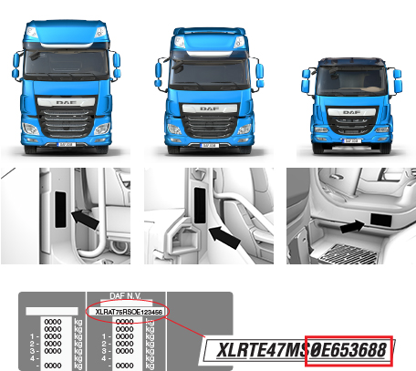
Search for your specific DAF Euro 6 user manuals by filling in the last 8 characters of your VIN-number (chassis number) and download the .pdf files. See the picture below for the exact location of your VIN-number in the truck.


Driver Manual Search
Invalid VIN Number
Last 8 characters — e.g. 0G142874
You didn’t select your language
-
##MANUALTITLE##
##MANUALFILENAME##
Downloads
Руководство на английском языке по техническому обслуживанию и ремонту DAF XF105.
- Автор: —
- Издательство: DAF
- Год издания: —
- Страниц: —
- Формат: PDF
- Размер: 12,1 Mb
Руководство на руссом языке по эксплуатации и техническому обслуживанию + каталог запчастей грузовых автомобилей DAF CF/XF105.
- Автор: —
- Издательство: Диез
- Год издания: —
- Страниц: 368
- Формат: —
- Размер: —

Краткое руководство по эксплуатации DAF XF105.
- Автор: —
- Издательство: DAF
- Год издания: —
- Страниц: 20
- Формат: PDF
- Размер: 1,2 Mb
Руководство по техническому обслуживанию и ремонту DAF XF95.
- Автор: —
- Издательство: Терция
- Год издания: —
- Страниц: 218
- Формат: —
- Размер: —
Руководство по ремонту и схемы электрооборудования DAF XF95.
- Автор: —
- Издательство: Диез
- Год издания: —
- Страниц: 616
- Формат: —
- Размер: —
Руководство по эксплуатации DAF XF105.
- Автор: —
- Издательство: DAF
- Год издания: —
- Страниц: 377
- Формат: PDF
- Размер: 3,7 Mb

Руководство по эксплуатации, техническому обслуживанию и ремонту + каталог деталей DAF 95XF 1997-2002 и DAF XF95 2002-2006 годов выпуска.
- Автор: —
- Издательство: Монолит
- Год издания: —
- Страниц: 689
- Формат: —
- Размер: —

Руководство по эксплуатации, техническому обслуживанию и ремонту + каталог деталей DAF XF105 с 2006 года выпуска.
- Автор: —
- Издательство: Монолит
- Год издания: —
- Страниц: 576
- Формат: —
- Размер: —

- Manuals
- Brands
- DAF Manuals
- Trucks
- LF45 Series
- Manual
-
Contents
-
Table of Contents
-
Bookmarks
Quick Links
9
LF45/55 series
0207
TECHNICAL DATA
SHOCK ABSORBERS
STABILISERS AND TORQUE RODS
LEAF SUSPENSION
CONTENTS
DIAGNOSTICS
CHASSIS
0
1
2
3
4
5
Related Manuals for DAF LF45 Series
Summary of Contents for DAF LF45 Series
-
Page 1
CONTENTS LF45/55 series TECHNICAL DATA DIAGNOSTICS CHASSIS SHOCK ABSORBERS STABILISERS AND TORQUE RODS LEAF SUSPENSION 0207… -
Page 2
fafsfsafa… -
Page 3
TECHNICAL DATA LF45/55 series Contents CONTENTS Page Date CHASSIS …………. . -
Page 4
TECHNICAL DATA LF45/55 series Contents 0207… -
Page 5
TECHNICAL DATA LF45/55 series Chassis 1. CHASSIS 1.1 GENERAL Chassis materials Type Chassis type Material KF 450 Note: KF 450 is a “High Tensile Strength”-steel grade. 0207… -
Page 6
TECHNICAL DATA LF45/55 series Chassis 0207… -
Page 7
TECHNICAL DATA LF45/55 series Shock absorbers, stabilisers, torque rods and leaf suspension 2. SHOCK ABSORBERS, STABILISERS, TORQUE RODS AND LEAF SUSPENSION 2.1 GENERAL Fixing the attachment bolts for the leaf spring Ensure that when fixing the attachment bolts (1) for the leaf spring that the leaf spring is at the prescribed height (A). -
Page 8
TECHNICAL DATA LF45/55 series Shock absorbers, stabilisers, torque rods and leaf suspension Transverse guide torque rod, air sprung rear axle LF45 Fitting angle (A) for mounting rubber on rear 8 — 12 ° axle side C9 00 408 Torque rods stabiliser length (A) A is the centre-to-centre-distance between the attachment points. -
Page 9
TECHNICAL DATA LF45/55 series Shock absorbers, stabilisers, torque rods and leaf suspension 2.2 TIGHTENING TORQUES The tightening torques stated in this paragraph are different from the standard tightening torques stated in the overview of the standard tightening torques. The other threaded connections which are not stated must therefore be tightened to the tightening torque stated in the overview of standard tightening torques. -
Page 10
TECHNICAL DATA LF45/55 series Shock absorbers, stabilisers, torque rods and leaf suspension LF45 rear axle, air suspension C9 00 323 M14 shock absorber attachment nut 52 Nm M12 air bellows attachment nut 31 Nm M20 bolt 525 Nm M12 air bellows attachment nut 60 Nm M20 shock absorber attachment bolt 525 Nm… -
Page 11
TECHNICAL DATA LF45/55 series Shock absorbers, stabilisers, torque rods and leaf suspension Rear axle, air suspension LF55 13- 15 ton C9 00 324 M16 triangular adjustment block 360 Nm attachment bolt M20 triangle attachment bolt 475 Nm Attachment nut for triangle on differential M22 235 Nm M20 shock absorber attachment bolt… -
Page 12
TECHNICAL DATA LF45/55 series Shock absorbers, stabilisers, torque rods and leaf suspension Rear axle, air suspension LF55 16- 18 ton C9 00 325 M10 air bellows attachment nut 46 Nm Clamping flange bolt M18 460 Nm M14 attachment bolt, property class 10.9 135 Nm M16 air bellows attachment bolt 195 Nm… -
Page 13
TECHNICAL DATA LF45/55 series Shock absorbers, stabilisers, torque rods and leaf suspension Steered rear axle, air suspension LF55 FAN C9 00 397 Self-locking nut, torque rod ball joint 88 Nm M20 shock absorber attachment bolt 250 Nm M10 air bellows attachment bolt 32 Nm M12 air bellows attachment bolt 34 Nm… -
Page 14
TECHNICAL DATA LF45/55 series Shock absorbers, stabilisers, torque rods and leaf suspension 0207… -
Page 15
DIAGNOSTICS LF45/55 series Contents CONTENTS Page Date SHOCK ABSORBERS ……….. -
Page 16
DIAGNOSTICS LF45/55 series Contents 0207… -
Page 17
DIAGNOSTICS LF45/55 series Shock absorbers 1. SHOCK ABSORBERS 1.1 FAULT-FINDING TABLE COMPLAINT: SHOCK ABSORBER PRODUCES NOISE (CHATTERING, BUMPING ETC.) Possible cause Remedy Shock absorber is loose. Tighten. Attachment rubbers too soft. Fit new rubbers. Shock absorber comes into contact with other Remove components or fasten them. -
Page 18
DIAGNOSTICS LF45/55 series Shock absorbers COMPLAINT: SHOCK ABSORBER TOO SOFT Possible cause Remedy Incorrect shock absorber type fitted. Fit correct type. Internal wear. Check shock absorber using a test bench and replace, if required. Loss of oil due to leakage. See under Leaky shock absorber. -
Page 19
DIAGNOSTICS LF45/55 series Leaf suspension 2. LEAF SUSPENSION 2.1 FAULT-FINDING TABLE COMPLAINT: LOOSE U-BOLTS Possible cause Remedy Use of a U-bolt or nut of an incorrect property Use U-bolts and nuts of the correct property class. class. The tightening torque used for the U-bolt nut Tighten the U-bolt to the specified torque. -
Page 20
DIAGNOSTICS LF45/55 series Leaf suspension COMPLAINT: SPLAYING OF THE SPRING ASSEMBLY (BROKEN SPRING CLAMPS) Possible cause Remedy Incorrect pre-tension of the U-bolts. See under complaint Loose U-bolts. COMPLAINT: SPRING HITS END STOP Possible cause Remedy Overloading. Adjust vehicle loading. Sagged spring assembly. Check height of both spring assemblies. -
Page 21
CHASSIS LF45/55 series Contents CONTENTS Page Date GENERAL …………. -
Page 22
CHASSIS LF45/55 series Contents 0207… -
Page 23
Any welding, aligning, drilling and wheelbase alteration activities that are not described in this workshop manual or in any of the latest releases of DAF’s Chassis Guidelines must be authorised by DAF. Following chassis repair, the cause of the chassis damage should be rectified. -
Page 24
CHASSIS LF45/55 series General Thoroughly grind out the crack on both sides. Take the necessary precautions to prevent damage to electronic components. Place the earth clamp as close as possible to the weld and avoid bridges. W9 01 002 Lay a bead on one side of the ground-out crack. -
Page 25
“Warm” straightening DAF chassis should not be warm straightened. Heating can cause grains in the material which will adversely affect the material properties. General… -
Page 26
Note: There are several stress zones in a chassis. Working on the chassis without the appropriate knowledge (and not according to DAF instructions) may cause irreversible damage to the chassis. The repair shop or bodybuilder would be held fully responsible for such work and for any superstructure fitted. -
Page 27
CHASSIS LF45/55 series General 1.3 REPLACING THE RIVETS BY BOLTS Note: A rivet may either be replaced by a flange bolt M14 x 2, property class 8.8 (DIN 6921), or a flange bolt M16 x 2, property class 10.9. Removing the rivet Remove the rivet head. -
Page 28
CHASSIS LF45/55 series General Installing M16 flange bolt Drill the rivet hole out to ∅17 mm. Make sure not to damage any lines running behind the rivet hole. Deburr the edges. Repair the chassis lacquer coating. The new paintwork should be no thicker than 50 microns. -
Page 29
SHOCK ABSORBERS LF45/55 series Contents CONTENTS Page Date GENERAL …………. -
Page 30
SHOCK ABSORBERS LF45/55 series Contents 0207… -
Page 31
A well-functioning shock absorber with characteristics appropriate to the operating conditions will be the best possible compromise to fulfil the above-mentioned functions. DAF only uses double acting type shock absorbers. On vehicles with air suspension, hydraulic stroke limitation is used. -
Page 32
SHOCK ABSORBERS LF45/55 series General Double acting shock absorbers The operation of the shock absorber is as follows: the bump stroke moves the cylinder (1) down in relation to the operating cylinder (2). Subsequently, oil flows from the bottom chamber of the piston (1) through the piston holes and valves to the top chamber where the volume increases. -
Page 33
SHOCK ABSORBERS LF45/55 series Removal and installation 2. REMOVAL AND INSTALLATION 2.1 REMOVAL AND INSTALLATION OF SHOCK ABSORBERS Remving the shock absorber Remove the attachment nuts and/or bolts. Mark the exact positions and location of the mounting rubbers. Remove the shock absorber from under the vehicle. -
Page 34
SHOCK ABSORBERS LF45/55 series Removal and installation 0207… -
Page 35
STABILISERS AND TORQUE RODS LF45/55 series Contents CONTENTS Page Date GENERAL …………. -
Page 36
STABILISERS AND TORQUE RODS LF45/55 series Contents 0207… -
Page 37
STABILISERS AND TORQUE RODS LF45/55 series General 1. GENERAL 1.1 OVERVIEW DRAWING, FRONT-AXLE STABILISER C9 00 400 Stabiliser bar Attachment bolt Silentblock Torque rod Shim Attachment bolt Lock nut Torque rod ball joint Attachment bolt 10. Clamp 11. Stabiliser bracket 12. -
Page 38
STABILISERS AND TORQUE RODS LF45/55 series General 1.2 OVERVIEW DRAWING, LEAF-SPRUNG REAR AXLE STABILISER C9 00 401 Silentblock Stabiliser bar Attachment bolt Bearing bush cover Bearing bush Bearing-bush cover 0207… -
Page 39
STABILISERS AND TORQUE RODS LF45/55 series General 1.3 OVERVIEW DRAWING, AIR-SPRUNG REAR AXLE STABILISER LF55 13-15 TON GVW C9 00 319 Stabiliser bar Clamp Bolt Retaining plate Bearing bush Bearing bush cover Stiffener Connecting pin 10. Shackle 11. Spacer ring 12. -
Page 40
STABILISERS AND TORQUE RODS LF45/55 series General 1.4 OVERVIEW DRAWING, AIR-SPRUNG REAR AXLE STABILISER LF55 16-18 TON GVW C9 00 320 Stabiliser bar Bolt Bracket Silentblock Shackle Bolt Silentblock 10. Nut 11. Bearing bush cover 12. Bearing bush 0207… -
Page 41
STABILISERS AND TORQUE RODS LF45/55 series General 1.5 OVERVIEW DRAWING, STEERED REAR AXLE STABILISER LF55 FAN C9 00 399 Stabiliser bar Torque rod Torque rod ball joint Lock nut Torque rod ball joint Lock nut Clamp Stabiliser bracket 10. Bearing bush 11. -
Page 42
STABILISERS AND TORQUE RODS LF45/55 series General 0207… -
Page 43
STABILISERS AND TORQUE RODS LF45/55 series Removal and installation 2. REMOVAL AND INSTALLATION 2.1 REMOVAL AND INSTALLATION, FRONT-AXLE STABILISER C9 00 400 Removal, front-axle stabiliser Remove the lock nut (9) from the ball joint (8). Press the ball joint (8) out of the stabiliser bar (1). -
Page 44
STABILISERS AND TORQUE RODS LF45/55 series Removal and installation Remove the stabiliser together with the bearing bushes (12) out of the vehicle supports (11). Remove the attachment bolts (6) and remove the torque rods (4). Installation, front-axle stabiliser Check the condition of the silentblocks (3), the bearing bushes (12) and the ball joints (8). -
Page 45
STABILISERS AND TORQUE RODS LF45/55 series Removal and installation 2.2 REMOVAL AND INSTALLATION, LEAF-SPRUNG REAR AXLE STABILISER C9 00 401 Removal, leaf-sprung rear axle stabiliser Remove the U-bolt nuts by means of which the mounting rubbers (1) of the stabiliser bar (2) are attached to the rear axle. -
Page 46
STABILISERS AND TORQUE RODS LF45/55 series Removal and installation Installation, leaf-sprung rear axle stabiliser Check the condition of the silentblocks (1) and the bearing bushes (5). Clean the threaded ends of the U-bolts. Fit the bearing bushes (5) in the bearing bush covers (4). -
Page 47
STABILISERS AND TORQUE RODS LF45/55 series Removal and installation 2.3 REMOVAL AND INSTALLATION, TRANSVERSE GUIDE TORQUE ROD, AIR SPRUNG REAR AXLE LF45 Removal, transverse guide torque rod Remove the attachment bolts (1) on the side (2) at which the torque rod (5) is attached to the rear axle. -
Page 48
STABILISERS AND TORQUE RODS LF45/55 series Removal and installation 2.4 REMOVAL AND INSTALLATION, AIR-SPRUNG REAR AXLE STABILISER LF55 13-15 TON GVW C9 00 319 Removal, air-sprung rear axle stabiliser bar LF55 13-15 ton GVW Remove the attachment bolts (3) and nuts (8) from the bearing bush covers (6) and stiffeners (7). -
Page 49
STABILISERS AND TORQUE RODS LF45/55 series Removal and installation Remove the attachment bolts and nuts from the shackle brackets (12) in the differential. Remove the stabiliser bar. Installation, air-sprung rear axle stabiliser bar LF55 13-15 ton GVW Check the condition of all the rubbers and hinge points. -
Page 50
STABILISERS AND TORQUE RODS LF45/55 series Removal and installation 2.5 REMOVAL AND INSTALLATION, TRIANGULAR LINK, AIR-SPRUNG REAR AXLE LF55 13-15 TON GVW C9 00 410 Removal, triangular link, air-sprung rear axle LF55 13-15 ton GVW Detach any valves on the inside of the chassis that may hinder removal of the triangular link. -
Page 51
STABILISERS AND TORQUE RODS LF45/55 series Removal and installation Installation, triangular link, air-sprung rear axle LF55 13-15 ton GVW Check the condition of the mounting rubbers and the silentblock in the triangle. Apply Copaslip to the silentblock attachment pin on the differential. Position the triangle on the attachment pin and check that the mounting rubbers are positioned straight against the support… -
Page 52
STABILISERS AND TORQUE RODS LF45/55 series Removal and installation 2.6 REMOVAL AND INSTALLATION, AIR-SPRUNG REAR AXLE YOKE LF55 13-15 TON GVW C9 00 410 Support the vehicle securely and work safely. Make sure that the axle cannot tilt if both yokes are removed at the same time. -
Page 53
STABILISERS AND TORQUE RODS LF45/55 series Removal and installation Installation, air-sprung rear axle yoke LF55 13-15 ton GVW Check the condition of the mounting rubber and the silentblock of the yoke. Position the yoke using a jack underneath the axle. Fit the attachment bolts (9) for the mounting rubber. -
Page 54
STABILISERS AND TORQUE RODS LF45/55 series Removal and installation 2.7 REMOVAL AND INSTALLATION, TRIANGULAR LINK AND AIR-SPRUNG REAR AXLE TORQUE ROD LF55 13-18 TON GVW C9 00 299 Removal, triangular link, air-sprung rear axle LF55 16-18 ton GVW, axle top Remove the bolts (2). -
Page 55
STABILISERS AND TORQUE RODS LF45/55 series Removal and installation Installation, triangular link, air-sprung rear axle LF55 16-18 ton GVW, axle top Before installation, check the rubber bushes of the triangular link and the silentblock for hair-line cracks and wear. Check to see if the contact surface of the triangular link flange (1) (see arrow) and the contact surface on the axle housing are free from grease and paint. -
Page 56
STABILISERS AND TORQUE RODS LF45/55 series Removal and installation 2.8 REMOVAL AND INSTALLATION, AIR-SPRUNG REAR AXLE STABILISER LF55 16-18 TON GVW C9 00 320 Removal, air-sprung rear axle stabiliser bar LF55 16-18 ton GVW Remove the attachment nuts (10) from the bearing bush covers (11). -
Page 57
STABILISERS AND TORQUE RODS LF45/55 series Removal and installation Installation, air-sprung rear axle stabiliser bar LF55 16-18 ton GVW Position the stabiliser bar (1) together with the bearing bushes (12) in the bearing bush cover halves underneath the differential. Fit the bearing bush covers (11) using the attachment bolts (10), but do not yet tighten the bolts. -
Page 58
STABILISERS AND TORQUE RODS LF45/55 series Removal and installation 2.9 REMOVAL AND INSTALLATION, STEERED REAR AXLE STABILISER LF55 C9 00 399 Removal, steered rear axle stabiliser bar LF55 FAN Remove the lock nuts (7) from the torque rod balls (5) on the side of the stabiliser bar (1) and press the balls out of the stabiliser bar. -
Page 59
STABILISERS AND TORQUE RODS LF45/55 series Removal and installation Remove the attachment bolts (12) together with the retaining plates (11) that are mounted to the stabiliser brackets (9) of the stabiliser bar. Remove the stabiliser together with the bearing bushes (10) out of the supports (9). Remove the lock nuts (4) from the torque rods on the chassis side and press the torque rods out of the spring stop brackets. -
Page 60
STABILISERS AND TORQUE RODS LF45/55 series Removal and installation 0207 2-18… -
Page 61
The silentblock should be fitted using special tool (DAF no. 1310476). It is not possible to install the silentblock undamaged, without using this puller. The stabiliser bar need not be removed when replacing the silentblocks on the stabiliser bar. -
Page 62
3.2 DISASSEMBLY AND ASSEMBLY, STABILISER BAR / TORQUE ROD SILENTBLOCK WITH STEEL CASING Notes The silentblocks with steel casing should be fitted using special tool (DAF no. 1310479). It is not possible to install the silentblock undamaged, without using this puller. The stabiliser bar need not be removed when replacing the silentblocks. -
Page 63
STABILISERS AND TORQUE RODS LF45/55 series Disassembly and assembly Installing silentblock with steel casing Place the thrust piece with the largest diameter (C in the drawing) on the puller (A). Apply for example tyre grease to the thrust piece, and place the puller (A) with the silentblock (1) on the stabiliser bar (2). -
Page 64
STABILISERS AND TORQUE RODS LF45/55 series Disassembly and assembly Disassembling the transverse guide torque rod mounting rubber, air-sprung rear axle LF45, chassis side Remove the torque rod from the vehicle. Drive the pin and rubber bush unit from the eye of the torque rod. Assembling the transverse guide torque rod mounting rubber, air-sprung rear axle LF45, chassis side… -
Page 65
STABILISERS AND TORQUE RODS LF45/55 series Disassembly and assembly 3.5 DISASSEMBLY AND ASSEMBLY, TRIANGULAR LINK MOUNTING RUBBER, AIR-SPRUNG REAR AXLE LF55 13-15 TON GVW Disassembly, triangular link mounting rubber Remove the triangular link from the vehicle. Remove the mounting rubber (1) from the triangular link (2) using a puller. -
Page 66
STABILISERS AND TORQUE RODS LF45/55 series Disassembly and assembly 3.6 DISASSEMBLY AND ASSEMBLY, TRIANGULAR LINK SILENTBLOCK, AIR-SPRUNG REAR AXLE LF55 16-18 TON GVW Disassembly, triangular link silentblock, air-sprung rear axle LF55 16-18 ton GVW Loosen the attachment bolts (7) a few turns. Remove the bolt (1). -
Page 67
STABILISERS AND TORQUE RODS LF45/55 series Disassembly and assembly Fit the circlip (3) as indicated. Make sure that the entire circlip (3) is positioned correctly in the groove. Install the flange (5), if removed, on the axle housing. Check to see if the contact surface of the flange (5) and the contact surface on the axle housing are free from grease and paint. -
Page 68
STABILISERS AND TORQUE RODS LF45/55 series Disassembly and assembly 3.7 DISASSEMBLY AND ASSEMBLY, TRIANGULAR LINK/TORQUE ROD MOUNTING RUBBER, AIR-SPRUNG REAR AXLE LF55 16-18 TON GVW Note: Disassembly and assembly of the mounting rubbers are identical for the triangular link and the torque rod. -
Page 69: Table Of Contents
LEAF SUSPENSION LF45/55 series Contents CONTENTS Page Date SAFETY INSTRUCTIONS ……….
-
Page 70
LEAF SUSPENSION LF45/55 series Contents 0207… -
Page 71: Safety Instructions
LEAF SUSPENSION LF45/55 series Safety instructions 1. SAFETY INSTRUCTIONS Spring leaves Spring leaves should not be subjected to blasting. Blasting will cause indentations in the leaf spring which could initiate pitting corrosion. Corrosion should be prevented as this will considerably shorten the service life of the spring.
-
Page 72
LEAF SUSPENSION LF45/55 series Safety instructions 0207… -
Page 73: General
LEAF SUSPENSION LF45/55 series General 2. GENERAL 2.1 DESCRIPTION OF LEAF SUSPENSION Parabolic springs are used on the LF series In a parabolic spring all the leaves are approximately the same length but the thickness of each leaf varies parabolically along its length. Except at the centre clamping and at the spring leaf ends, the spring leaves of a parabolic leaf w9 04 002…
-
Page 74: Overview Drawing, Spring Assembly With Bolt Attachment
LEAF SUSPENSION LF45/55 series General 2.2 OVERVIEW DRAWING, SPRING ASSEMBLY WITH BOLT ATTACHMENT Note: This drawing gives a general view and may differ from the actual situation on the vehicle. C9 00 305 Attachment bolt Centring sleeve Spring bracket U-bolt Upper spring seat Shock absorber support U-bolt nut…
-
Page 75: Overview Drawing, Spring Assembly With Pin Attachment
LEAF SUSPENSION LF45/55 series General 2.3 OVERVIEW DRAWING, SPRING ASSEMBLY WITH PIN ATTACHMENT Note: This drawing gives a general view and may differ from the actual situation on the vehicle. C9 00 326 Attachment bolt 10. Spring bracket Mounting bracket 11.
-
Page 76
LEAF SUSPENSION LF45/55 series General 0207… -
Page 77: Removal And Installation
LEAF SUSPENSION LF45/55 series Removal and installation 3. REMOVAL AND INSTALLATION 3.1 REMOVAL AND INSTALLATION, SPRING ASSEMBLY WITH BOLT ATTACHMENT C9 00 411 Support the vehicle securely and work safely. Make sure that the axle cannot tilt if both spring assemblies are removed at the same time.
-
Page 78
LEAF SUSPENSION LF45/55 series Removal and installation Installation, spring assembly with bolt attachment Check that all contact faces are free of dirt, grease and paint. If applicable, fit the wedge in the correct position. Install the spring assembly to the spring plate/shock absorber plate. -
Page 79: Removal And Installation, Spring Assembly With Pin Attachment
LEAF SUSPENSION LF45/55 series Removal and installation 3.2 REMOVAL AND INSTALLATION, SPRING ASSEMBLY WITH PIN ATTACHMENT C9 00 412 Support the vehicle securely and work safely. Make sure that the axle cannot tilt if both spring assemblies are removed at the same time. Removal, spring assembly with pin attachment Remove all components which are in the…
-
Page 80
LEAF SUSPENSION LF45/55 series Removal and installation Installation, spring assembly with pin attachment Check that all contact faces are free of dirt, grease and paint. If applicable, fit the wedge in the correct position. Install the spring assembly to the spring plate/shock absorber plate. -
Page 81: Removal And Installation, Steered Rear Axle Spring Assembly Lf55 Fan
LEAF SUSPENSION LF45/55 series Removal and installation 3.3 REMOVAL AND INSTALLATION, STEERED REAR AXLE SPRING ASSEMBLY LF55 FAN Support the vehicle securely and work safely. Make sure that the axle cannot tilt if both spring assemblies are removed at the same time. Removal, steered rear axle spring assembly LF55 FAN Remove the stabiliser bar together with the…
-
Page 82
LEAF SUSPENSION LF45/55 series Removal and installation Installation, steered rear axle spring assembly LF55 FAN Check that all contact faces are free of dirt, grease and paint. Install the spring assembly to the lower spring seat. This can only be done by two persons working together. -
Page 83: Removal And Installation, Spring Bracket
LEAF SUSPENSION LF45/55 series Removal and installation 3.4 REMOVAL AND INSTALLATION, SPRING BRACKET Support the vehicle, axle or spring assembly securely and work safely. Removal, spring bracket Jack up the chassis until the spring or the yoke is free of stress. Remove the spring or yoke bracket.
-
Page 84
LEAF SUSPENSION LF45/55 series Removal and installation 0207…
DAF respects your privacy. We use cookies for a variety of purposes, such as website functionality, improving your experience of our website, building integration with social media and helping target marketing activities within and beyond our website. By continuing your visit on our website, you are consenting to our use of cookies. However, if you want to customize your cookie preferences, click on ‘Change settings’ below. You can withdraw your consent at any time. For more information, please visit our Cookie Notice.
Driver manuals
DAF Driver’s Manuals contain important information that is essential to making operation of a DAF vehicle as efficient, safe and enjoyable as possible.
The DAF Quick Reference Guide is designed to help you get the most out of your truck in the shortest possible time.
You can find your specific manuals by entering the last eight characters of your VIN. You can then download the PDF files.
The images on the right show the exact location of the VIN in the truck.
Driver Manual Search
Invalid VIN Number
Last 8 characters — e.g. 0G142874
You didn’t select your language
-
##MANUALTITLE##
##MANUALFILENAME##
Downloads