Комментарии
10
Войдите или зарегистрируйтесь, чтобы писать комментарии, задавать вопросы и участвовать в обсуждении.
Войти
Зарегистрироваться

AutoBOTT
Я езжу на Nissan X-Trail I
Можете закинут на Яндекс диск мануал на Xtrail T30, не как не разберусь с Dropbox…
9 месяцев

Romanov-86
Я езжу на Nissan X-Trail II
спасибо. скачал.
6 лет

kyrok84
Я езжу на Jeep Grand Cherokee (WK2)
Есть книга Эксплуатация, обслуживание и ремонт Хитрого с 2007 г. и рестал 2011 г., кому надо пишите, залью куда-нить типа Яндекс диска…
7 лет

ComeAgain
Я езжу на Honda Fit (3G)
отличные ссылки. скачал — спасибо!
7 лет

toor76
Автор
Я езжу на Nissan X-Trail II
Пожалуста)
7 лет

Energy73RUS
Я езжу на Volkswagen Tiguan (2G)
Спасибо, в закладки!
7 лет

SKORPIONCIK
Я езжу на Nissan X-Trail II
а че подругому нельзя скачать?
7 лет
toor76
Автор
Я езжу на Nissan X-Trail II
Черкни куда залить и что именно)
7 лет

sibers42
Я езжу на Honda Stream
Спасибо)
7 лет
toor76
Автор
Я езжу на Nissan X-Trail II
Всегда рад помочь)
7 лет
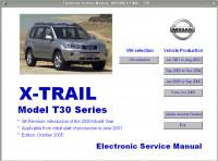
Мультимедийное руководство на английском языке по техническому обслуживанию и ремонту автомобиля Nissan X-Trail серии T30 с 2001 года выпуска.
- Автор: —
- Издательство: Nissan
- Год издания: 2006
- Страниц: —
- Формат: —
- Размер: 266,9 Mb
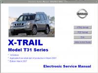
Мультимедийное руководство на английском языке по техническому обслуживанию и ремонту автомобиля Nissan X-Trail серии T31 с 2007 года выпуска.
- Автор: —
- Издательство: Nissan
- Год издания: 2007
- Страниц: —
- Формат: —
- Размер: 365,6 Mb
Руководство на английском языке по техническому обслуживанию и ремонту автомобиля Nissan X-Trail серии T32.
- Автор: —
- Издательство: Nissan
- Год издания: —
- Страниц: —
- Формат: —
- Размер: 196,7 Mb
Мультимедийное руководство на английском языке по техническому обслуживанию и ремонту автомобиля Nissan X-Trail серии T31.
- Автор: —
- Издательство: Nissan
- Год издания: —
- Страниц: —
- Формат: ISZ
- Размер: 197,3 Mb
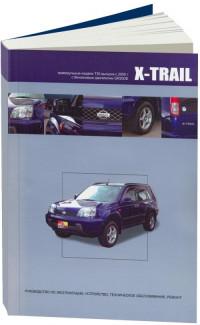
Руководство по техническому обслуживанию и ремонту автомобиля Nissan X-Trail серии T30 2000-2007 годов выпуска с бензиновыми двигателями объемом 2,0/2,5 л.
- Автор: —
- Издательство: Автонавигатор
- Год издания: —
- Страниц: 480
- Формат: —
- Размер: —
Руководство по эксплуатации и ремонту автомобилей Nissan Roque и Nissan X-Trail серии T31 с 2007 года выпуска с бензиновыми и дизельными двигателями.
- Автор: —
- Издательство: Монолит
- Год издания: —
- Страниц: 430
- Формат: —
- Размер: —
Руководство по эксплуатации и ремонту автомобиля Nissan X-Trail с 2014 года выпуска с бензиновыми и дизельными двигателями.
- Автор: —
- Издательство: Монолит
- Год издания: —
- Страниц: 526
- Формат: —
- Размер: —
Руководство по эксплуатации и техническому обслуживанию автомобиля Nissan X-Trail 2000-2007 годов выпуска.
- Автор: —
- Издательство: MoToR
- Год издания: —
- Страниц: 240
- Формат: —
- Размер: —
Руководство по эксплуатации и техническому обслуживанию автомобиля Nissan X-Trail 2007-2015 годов выпуска.
- Автор: —
- Издательство: MoToR
- Год издания: —
- Страниц: 337
- Формат: —
- Размер: —
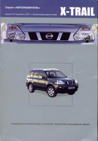
Руководство по эксплуатации и техническому обслуживанию автомобиля Nissan X-Trail с 2007 года выпуска.
- Автор: —
- Издательство: Nissan
- Год издания: —
- Страниц: 325
- Формат: PDF
- Размер: 12,0 Mb
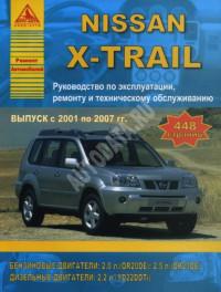
Руководство по эксплуатации, техническому обслуживанию и ремонту автомобиля Nissan X-Trail 2001-2007 годов выпуска с бензиновыми и дизельными двигателями.
- Автор: —
- Издательство: Арго-Авто
- Год издания: —
- Страниц: 448
- Формат: —
- Размер: —
Руководство по эксплуатации, техническому обслуживанию и ремонту автомобиля Nissan X-Trail с 2000 года выпуска с бензиновыми двигателями.
- Автор: —
- Издательство: Автонавигатор
- Год издания: 2005
- Страниц: 484
- Формат: PDF
- Размер: 54,0 Mb
Руководство по эксплуатации, техническому обслуживанию и ремонту автомобиля Nissan X-Trail серии T30 с 2000 года выпуска с бензиновым двигателем объемом 2,0 л.
- Автор: —
- Издательство: Автонавигатор
- Год издания: —
- Страниц: 400
- Формат: —
- Размер: —
Руководство по эксплуатации, техническому обслуживанию и ремонту автомобиля Nissan X-Trail серии T31 с 2007 года выпуска с бензиновыми двигателями.
- Автор: —
- Издательство: Автонавигатор
- Год издания: 2008
- Страниц: 375
- Формат: DjVu
- Размер: 12,7 Mb
Руководство по техническому обслуживанию и ремонту автомобиля Nissan X-Trail серии T31 2007-2014 годов выпуска с бензиновыми двигателями объемом 2,0/2,5 л
- Автор: —
- Издательство: Автонавигатор
- Год издания: —
- Страниц: 376
- Формат: —
- Размер: —
Руководство по техническому обслуживанию и ремонту автомобиля Nissan X-Trail серии T31 2007-2010 годов выпуска с бензиновыми двигателями объемом 2,0/2,5 л.
- Автор: —
- Издательство: Автонавигатор
- Год издания: —
- Страниц: 752
- Формат: PDF
- Размер: 95,9 Mb
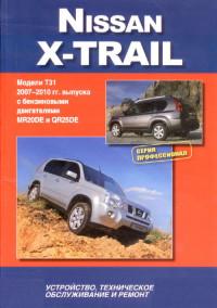
Руководство по техническому обслуживанию и ремонту автомобиля Nissan X-Trail серии T31 с 2007 года выпуска с бензиновыми двигателями объемом 2,0/2,5 л.
- Автор: —
- Издательство: Автонавигатор
- Год издания: —
- Страниц: 752
- Формат: —
- Размер: —
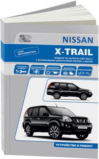
Руководство по техническому обслуживанию и ремонту автомобиля Nissan X-Trail серии T32 с 2014 года выпуска с бензиновыми и дизельными двигателями.
- Автор: —
- Издательство: Автонавигатор
- Год издания: —
- Страниц: 700
- Формат: —
- Размер: —
Руководство по эксплуатации, техническому обслуживанию и ремонту автомобиля Nissan X-Trail с 2007 года выпуска с бензиновыми двигателями объемом 2,0/2,5 л.
- Автор: —
- Издательство: Мир Автокниг
- Год издания: 2012
- Страниц: 511
- Формат: PDF
- Размер: 104,9 Mb
Руководство по эксплуатации, техническому обслуживанию и ремонту автомобиля Nissan X-Trail с 2015 года выпуска.
- Автор: —
- Издательство: Мир Автокниг
- Год издания: —
- Страниц: 384
- Формат: —
- Размер: —

![]()
K ELECTRICAL
SECTION DI
DRIVER INFORMATION SYSTEM
CONTENTS
|
PRECAUTIONS ………………………………………………… |
3 |
|
|
Precautions for Supplemental Restraint System |
||
|
(SRS) “AIR BAG” and “SEAT BELT PRE-TEN- |
||
|
SIONER” ……………………………………………………….. |
3 |
|
|
Wiring Diagrams and Trouble Diagnosis …………….. |
3 |
|
|
COMBINATION METERS …………………………………… |
4 |
|
|
System Description …………………………………………. |
4 |
|
|
UNIFIED METER CONTROL UNIT ………………… |
4 |
|
|
POWER SUPPLY AND GROUND CIRCUIT ……. |
4 |
|
|
ODO/TRIP METER, CLOCK AND AMBIENT |
||
|
TEMPERATURE INDICATOR ………………………… |
4 |
|
|
SPEEDOMETER ………………………………………….. |
4 |
|
|
TACHOMETER ……………………………………………. |
5 |
|
|
WATER TEMPERATURE GAUGE ………………….. |
5 |
|
|
FUEL GAUGE ……………………………………………… |
5 |
|
|
AMBIENT TEMPERATURE INDICATOR …………. |
5 |
|
|
CAN Communication ……………………………………….. |
6 |
|
|
SYSTEM DESCRIPTION ………………………………. |
6 |
|
|
CAN COMMUNICATION UNIT ………………………. |
6 |
|
|
Arrangement of Combination Meter …………………… |
7 |
|
|
ComponentPartsandHarnessConnectorLocation….. |
8 |
|
|
Schematic ……………………………………………………… |
9 |
|
|
Wiring Diagram — METER — ……………………….. |
… 10 |
|
|
AWD MODELS …………………………………………… |
10 |
|
|
2WD MODELS …………………………………………… |
12 |
|
|
Terminals and Reference Value for Combination |
||
|
Meter …………………………………………………………… |
14 |
|
|
Self-Diagnosis Mode of Combination Meter ………. |
14 |
|
|
SELF-DIAGNOSIS FUNCTION ……………………. |
14 |
|
|
OPERATION PROCEDURE ………………………… |
14 |
|
|
Trouble Diagnosis …………………………………………. |
15 |
|
|
HOW TO PROCEED WITH TROUBLE DIAGNO- |
||
|
SIS …………………………………………………………… |
15 |
|
|
PRELIMINARY CHECK ………………………………. |
15 |
|
|
SYMPTOM CHART …………………………………….. |
16 |
|
|
Power Supply and Ground Circuit Inspection ……. |
16 |
|
|
Vehicle Speed Signal Inspection (With VDC) …….. |
17 |
|
|
Vehicle Speed Signal Inspection (Without VDC) . |
.. |
17 |
|
Engine Speed Signal Inspection ……………………… |
17 |
|
|
Engine Coolant Temperature Signal Inspection …. |
18 |
|
Fuel Level Sensor Inspection ………………………….. |
18 |
|
|
The Fuel Gauge Pointer Fluctuates, Indicator |
||
|
Wrong Value or Varies ……………………………………. |
19 |
|
|
The Fuel Gauge Does Not Move to FULL Position… |
20 |
|
|
Ambient Temperature Signal Inspection [Without |
||
|
Auto A/C] ……………………………………………………… |
20 |
|
|
Ambient Temperature Signal Inspection [With Auto |
||
|
A/C] ……………………………………………………………… |
22 |
|
|
Electrical Components Inspection ……………………. |
23 |
|
|
FUEL LEVEL SENSOR UNIT CHECK …………… |
23 |
|
|
AMBIENT SENSOR CHECK ………………………… |
23 |
|
|
Removal and Installation for Combination Meter |
... |
24 |
|
REMOVAL …………………………………………………. |
24 |
|
|
INSTALLATION ………………………………………….. |
24 |
|
|
Disassembly and Assembly for Combination Meter… |
24 |
|
|
DISASSEMBLY ………………………………………….. |
24 |
|
|
ASSEMBLY ……………………………………………….. |
24 |
|
|
WARNING LAMPS …………………………………………… |
25 |
|
|
Schematic …………………………………………………….. |
25 |
|
|
Wiring Diagram — WARN — …………………………. |
… 26 |
|
|
AWD MODELS …………………………………………… |
26 |
|
|
2WD MODELS ……………………………………………. |
32 |
|
|
Electrical Components Inspection ……………………. |
38 |
|
|
OIL PRESSURE SWITCH CHECK ……………….. |
38 |
|
|
DIODE CHECK ………………………………………….. |
38 |
|
|
A/T INDICATOR ………………………………………………. |
39 |
|
|
Wiring Diagram — AT/IND — ………………………… |
… 39 |
|
|
AWD MODELS …………………………………………… |
39 |
|
|
2WD MODELS ……………………………………………. |
40 |
|
|
A/T Indicator Does Not Illuminate …………………….. |
41 |
|
|
WARNING CHIME ……………………………………………. |
42 |
|
|
System Description ………………………………………… |
42 |
|
|
POWER SUPPLY AND GROUND CIRCUIT …… |
42 |
|
|
IGNITION KEY WARNING CHIME ……………….. |
42 |
|
|
LIGHT WARNING CHIME ……………………………. |
42 |
|
|
SEAT BELT WARNING CHIME …………………….. |
42 |
|
|
ComponentPartsandHarnessConnectorLocation… 43 |
||
|
Schematic …………………………………………………….. |
44 |
|
|
Wiring Diagram — CHIME — ………………………… |
… 45 |
|
|
Terminals and Reference Value for Smart Entrance |
|
Revision: 2005 March |
DI-1 |
2005 X-Trail |

|
Control Unit …………………………………………………… |
48 |
Key Switch Insert Signal Inspection ………………….. |
51 |
|
Trouble Diagnosis ………………………………………….. |
48 |
Seat Belt Buckle Switch Input Signal Inspection |
|
|
HOW TO PROCEED WITH TROUBLE DIAGNO- |
[Without Power Seat] ……………………………………… |
52 |
|
|
SIS ……………………………………………………………. |
48 |
Seat Belt Buckle Switch Input Signal Inspection |
|
|
SYMPTOM CHART …………………………………….. |
48 |
[With Power Seat] ………………………………………….. |
54 |
|
Power Supply and Ground Circuit Inspection …….. |
48 |
CLOCK …………………………………………………………… |
56 |
|
Front Door Switch (Driver Side) Inspection ……….. |
49 |
Wiring Diagram — CLOCK — ………………………… |
…56 |
|
Lighting Switch Input Signal Inspection …………….. |
51 |
|
Revision: 2005 March |
DI-2 |
2005 X-Trail |

PRECAUTIONS |
|||
|
PRECAUTIONS |
PFP:00011 |
A |
|
|
Precautions for Supplemental Restraint System (SRS) “AIR BAG” and “SEAT |
|||
|
BELT PRE-TENSIONER” |
AKS00B9V |
|
The Supplemental Restraint System such as “AIR BAG” and “SEAT BELT PRE-TENSIONER”, used along B |
||
|
with a front seat belt, helps to reduce the risk or severity of injury to the driver and front passenger for certain |
||
|
types of collision. Information necessary to service the system safely is included in the SRS and SB section of |
||
|
this Service Manual. |
C |
|
|
WARNING: |
||
●To avoid rendering the SRS inoperative, which could increase the risk of personal injury or death in the event of a collision which would result in air bag inflation, all maintenance must be per-
formed by an authorized NISSAN/INFINITI dealer.
●Improper maintenance, including incorrect removal and installation of the SRS, can lead to personal injury caused by unintentional activation of the system. For removal of Spiral Cable and Air
Bag Module, see the SRS section.
●Do not use electrical test equipment on any circuit related to the SRS unless instructed to in this Service Manual. SRS wiring harnesses can be identified by yellow and/or orange harnesses or
harness connectors.
Wiring Diagrams and Trouble Diagnosis |
AKS00B9W |
When reading wiring diagrams, refer to the following:
●GI-14, «How to Read Wiring Diagrams» in GI section
●PG-2, «POWER SUPPLY ROUTING» for power distribution circuit in PG section When performing trouble diagnosis, refer to the following:
●GI-10, «HOW TO FOLLOW TEST GROUPS IN TROUBLE DIAGNOSES» in GI section
●GI-26, «How to Perform Efficient Diagnosis for an Electrical Incident» in GI section
|
Revision: 2005 March |
DI-3 |
2005 X-Trail |

COMBINATION METERS
COMBINATION METERS
System Description
UNIFIED METER CONTROL UNIT
●Speedometer, odo/trip meter, tachometer, fuel gauge and water temperature gauge are controlled by the unified meter control unit, which is built into the combination meter.
●Digital meter is adopted for odo/trip meter*.
*The record of the odo meter is kept even if the battery cable is disconnected. The record of the trip meter is erased when the battery cable is disconnected.
●Meter/gauge and odo/trip meter segments can be checked in diagnosis mode.
POWER SUPPLY AND GROUND CIRCUIT
Power is supplied at all times
●through 10 A fuse [No. 28, located in the fuse block (J/B)]
●to combination meter terminal 1.
With the ignition switch in the ON or START position, power is supplied
●through 10 A fuse [No. 11, located in the fuse block (J/B)]
●to combination meter terminal 2.
Ground is supplied
●to combination meter terminal 21
●through grounds M27 and M70.
ODO/TRIP METER, CLOCK AND AMBIENT TEMPERATURE INDICATOR
●The vehicle speed signal and the memory signals from the meter memory circuit are processed by the combination meter and the mileage is displayed.
●Ambient temperature indicator indicates signal from ambient sensor processed by the combination meter.
How to Change The Display
Depressing the odo/trip meter switch toggles the mode in the following order.
SKIA8917E
●The odo/trip meter display mode toggling and trip display resetting can be identified by the amount of time that elapses from pressing the odo/trip meter switch to releasing it.
●When resetting with trip A displayed, only trip A display is reset. (The same way for trip B.)
SPEEDOMETER
VDC/TCS/ABS control unit [with VDC] or ABS actuator and electric unit (control unit) [without VDC] provides a vehicle speed signal to the combination meter for the speedometer with CAN communication line.
|
Revision: 2005 March |
DI-4 |
2005 X-Trail |

COMBINATION METERS
TACHOMETER
The tachometer indicates engine speed in revolutions per minute (rpm).
ECM provides an engine speed signal to combination meter for tachometer with CAN communication line.
WATER TEMPERATURE GAUGE
The water temperature gauge indicates the engine coolant temperature.
ECM provides an engine coolant temperature signal to combination meter for water temperature gauge with CAN communication line.
FUEL GAUGE
The fuel gauge indicates the approximate fuel level in the fuel tank.
The fuel gauge is regulated by a variable ground signal supplied
●from grounds M27 and M70
●through terminals 1 and 4 of the fuel level sensor unit
●through terminals 3 and 1 of the sub fuel level sensor unit and
●to combination meter terminal 8 for the fuel gauge.
AMBIENT TEMPERATURE INDICATOR
The ambient temperature is indicated by the signal from ambient sensor.
Combination meter inputs voltage conversed from resistance which ambient sensor detects.
Indication range is between -30 and 55 ° C (-22 and 131 ° F). When ambient temperature is less than -30 ° C (- 22 ° F) or more than 55 ° C (131 ° F), display shows “—° C”. When indicated temperature becomes less than 3 ° C (37 ° F), ambient temperature indicator flashes as a sign of warning.
Without Auto A/C
Power is supplied
●through combination meter terminal 27
●to ambient sensor terminal 1.
Ground is supplied
●to combination meter terminal 28
●through ambient sensor terminal 2. Signal is supplied
●through ambient sensor terminal 1
●to combination meter terminal 27.
With Auto A/C
Power is supplied
●through A/C auto amp. terminal 9
●to ambient sensor terminal 1. Ground is supplied
●to combination meter terminal 28 and A/C auto amp. terminal 24
●through ambient sensor terminal 2.
And combination meter receives ambient sensor signal from ambient sensor
●through ambient sensor terminal 1
●to combination meter terminal 27.
NOTE:
Combination meter distinguishes whether or not combination meter terminal 29 receives voltage (Auto A/C recognition signal) from A/C auto amp. terminal 28. If the terminal receives, combination meter discerns as auto A/C.
Indication When Turning Ignition Switch OFF
●In a case that temperature detected by ambient sensor is higher than indicated temperature before turning ignition switch off.
–In a case of more than 3.5 hours after turning ignition switch off, temperature detected by ambient sensor is indicated when turning ignition switch on.
A
B
C
D
E
F
G
H
I
J
DI
L
M
|
Revision: 2005 March |
DI-5 |
2005 X-Trail |

COMBINATION METERS
–In a case of less then 3.5 hours after turning ignition switch off, temperature at the time of turning ignition switch off is indicated.
●In a case that temperature detected by ambient sensor is lower than indicated temperature before turning ignition switch off.
–Temperature detected by ambient sensor is indicated when turning ignition switch on.
Indication During Running
Though temperature detected by ambient sensor temporarily changed, indicating temperature continentally indicates.
●In a case that temperature detected by ambient sensor is higher than indicated temperature.
–If vehicle speed is more than 20 km/h (13 MPH), elevation of indicating temperature is limited according to the speed until temperature detected by ambient sensor is indicated.
NOTE:
Vehicle speed 20 km/h (13 MPH): 256 sec., 25 km/h (16 MPH): 238 sec., 35 km/h (22 MPH): 200 sec., 50 km/h (31 MPH): 144 sec., 65 km/h (40 MPH): 88 sec., more than 80 km/h (50 MPH): 32 sec.
–If vehicle speed is more than 20 km/h (13 MPH), and that temperature detected by ambient sensor becomes 8 ° C (46 ° F) more than indicating temperature, indicating temperature will be elevated unit the
degree becomes same as temperature detected by ambient sensor with limiting elevation of indicating temperature 1 ° C par a minute.
–If vehicle speed is less than 20 km/h (13 MPH), indicating temperature is continually kept.
● In a case that temperature detected by ambient sensor is lower than indicated temperature.
–Temperature detected by ambient sensor is indicated during running.
CAN Communication |
AKS00BQ7 |
SYSTEM DESCRIPTION
CAN (Controller Area Network) is a serial communication line for real time application. It is an on-vehicle multiplex communication line with high data communication speed and excellent error detection ability. Many electronic control units are equipped onto a vehicle, and each control unit shares information and links with other control units during operation (not independent). In CAN communication, control units are connected with 2 communication lines (CAN H line, CAN L line) allowing a high rate of information transmission with less wiring. Each control unit transmits/receives data but selectively reads required data only.
CAN COMMUNICATION UNIT
Refer to LAN-16, «CAN Communication Unit» in “LAN SYSTEM”.
|
Revision: 2005 March |
DI-6 |
2005 X-Trail |
COMBINATION METERS
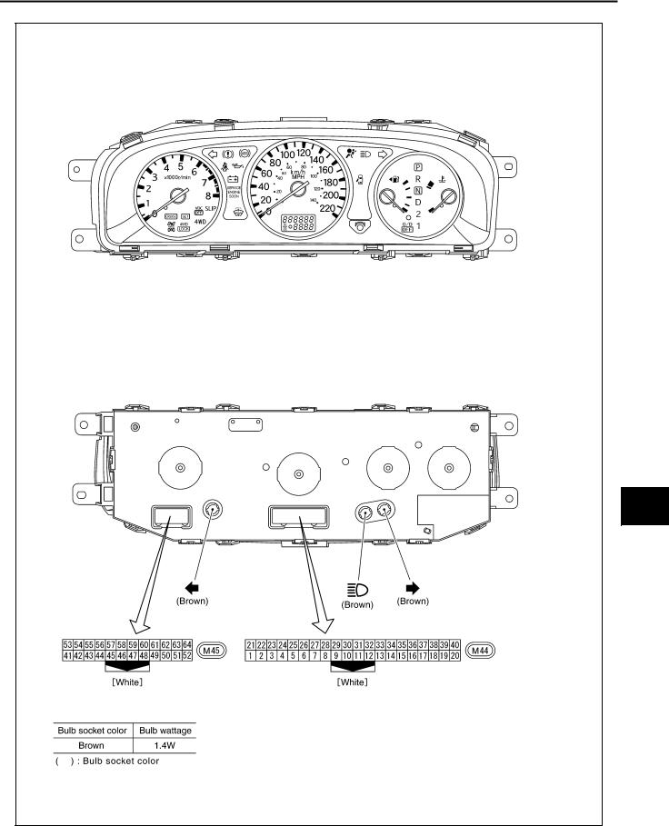
Arrangement of Combination Meter
AKS00BA1
A
B
C
D
E
F
G
H
I
J
DI
L
M
SKIB0505E
|
Revision: 2005 March |
DI-7 |
2005 X-Trail |
COMBINATION METERS
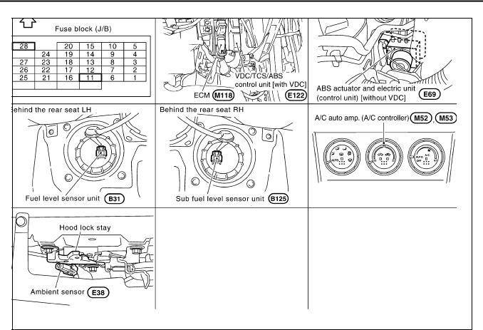
Component Parts and Harness Connector Location AKS00BA0
SKIB0506E
|
Revision: 2005 March |
DI-8 |
2005 X-Trail |
COMBINATION METERS
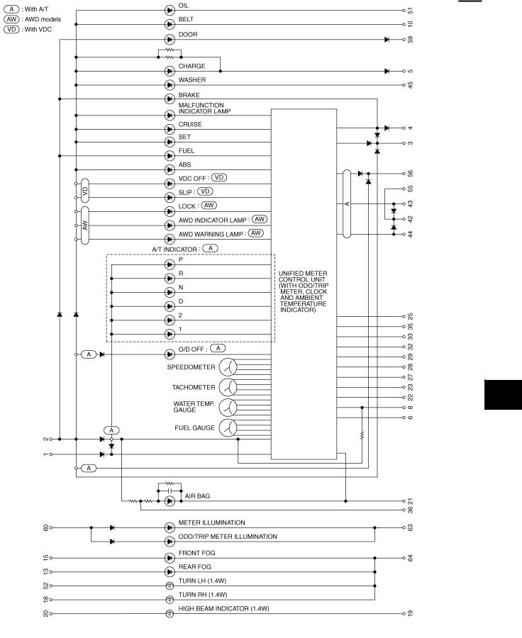
Schematic
AKS00BA2
A
B
C
D
E
F
G
H
I
J
DI
L
M
TKWB0170E
|
Revision: 2005 March |
DI-9 |
2005 X-Trail |

COMBINATION METERS
Wiring Diagram — METER —
AWD MODELS
|
Revision: 2005 March |
DI-10 |
2005 X-Trail |
![]()
COMBINATION METERS
A
B
C
D
E
F
G
H
I
J
DI
L
M
TKWB0172E
|
Revision: 2005 March |
DI-11 |
2005 X-Trail |

COMBINATION METERS
2WD MODELS
TKWB0173E
|
Revision: 2005 March |
DI-12 |
2005 X-Trail |

COMBINATION METERS
A
B
C
D
E
F
G
H
I
J
DI
L
M
TKWB0174E
|
Revision: 2005 March |
DI-13 |
2005 X-Trail |

COMBINATION METERS
Terminals and Reference Value for Combination Meter |
AKS00BA6 |
||||||
|
Terminal |
Wire |
Condition |
|||||
|
Item |
Reference Value |
||||||
|
No. |
Color |
Ignition |
Operation or condition |
||||
|
switch |
|||||||
|
1 |
L |
Battery power supply |
OFF |
— |
Battery voltage |
||
|
2 |
Y/G |
Ignition switch (ON) |
ON |
— |
Battery voltage |
||
|
8 |
G |
Fuel level sensor signal |
— |
— |
Refer to DI-23, «FUEL LEVEL SEN- |
||
|
SOR UNIT CHECK» . |
|||||||
|
21 |
B |
Ground |
ON |
— |
Approx. 0 V |
||
|
22 |
W |
CAN-H |
— |
— |
— |
||
|
23 |
R |
CAN-L |
— |
— |
— |
||
|
27 |
R/B |
Ambient sensor signal |
— |
— |
Refer to DI-23, «AMBIENT SENSOR |
||
|
CHECK» |
|||||||
|
28 |
B/Y |
Ambient sensor ground |
— |
— |
— |
||
|
29*1 |
Y |
Auto A/C recognition signal |
ON |
— |
Approx. 5 V |
||
|
NOTE: |
|||||||
|
*1:With auto A/C |
|||||||
Self-Diagnosis Mode of Combination Meter |
AKS00BA7 |
SELF-DIAGNOSIS FUNCTION
●Odo/trip meter segment operation can be checked in self-diagnosis mode.
●Meters/gauges can be checked in self-diagnosis mode.
OPERATION PROCEDURE
1.Turn the ignition switch ON, and switch the odo/trip meter to “trip A” or “trip B”.
NOTE:
If the diagnosis function is activated with the trip meter A displayed, the mileage on the trip meter A will indicate 0.0 mile, but the actual trip mileage will be retained. (The same way for trip B.)
2.Turn ignition switch OFF.
3.While pushing the odo/trip meter switch, turn ignition switch ON again.
4.Make sure that the trip meter displays “0.0”.
5.Push the odo/trip meter switch at least 3 times. (Within 7 seconds after the ignition switch is turned ON.)
6.All the segments on the odo/trip meter illuminate, and simultaneously the low-fuel warning lamp indicator illuminates. At this time, the unified meter control unit is turned to diagnosis mode.
NOTE:
If any of the segments is not displayed, replace the combination meter.
SKIA8920E
|
Revision: 2005 March |
DI-14 |
2005 X-Trail |

COMBINATION METERS
7.Push the odo/trip meter switch. Each meter/gauge should indicate as shown in the figure while pushing odo/trip meter switch. (At this time, the low-fuel warning lamp goes off.)
|
SKIB0507E |
|
Trouble Diagnosis |
AKS00BQ6 |
HOW TO PROCEED WITH TROUBLE DIAGNOSIS |
1.Confirm the symptom or customer complaint.
2.Perform preliminary check. Refer to DI-15, «PRELIMINARY CHECK» .
3.According to the trouble diagnosis chart, repair or replace the cause of symptom. Refer to DI-16, «SYMPTOM CHART» .
4.Does the meter operate normally? If so, GO TO 5. If not, GO TO 2.
5.INSPECTION END
PRELIMINARY CHECK
1. CHECK WARNING LAMP ILLUMINATION
1.Turn ignition switch ON.
2.Make sure that warning lamp (such as MIL and oil pressure warning lamp) illuminate. Does warning lamp illuminate?
|
YES |
>> GO TO 2. |
|
NO |
>> GO TO 3. |
2. CHECK SELF-DIAGNOSIS OPERATION
Perform combination meter self-diagnosis. Refer to DI-14, «SELF-DIAGNOSIS FUNCTION» . Does self-diagnosis function operate?
|
YES |
>> GO TO 4. |
|
NO |
>> GO TO 3. |
3. CHECK POWER SUPPLY AND GROUND CIRCUIT
Check power supply and ground circuit. Refer to DI-16, «Power Supply and Ground Circuit Inspection» . OK or NG
|
OK |
>> Replace combination meter. |
|
NG |
>> Repair as need. |
4. CHECK ODO/TRIP METER OPERATION
Check segment display status of odo/trip meter.
Is the display normal?
|
YES |
>> GO TO 5. |
|
NO |
>> Replace combination meter. |
SKIA8920E
A
B
C
D
E
F
G
H
I
J
DI
L
M
|
Revision: 2005 March |
DI-15 |
2005 X-Trail |

COMBINATION METERS
5. CHECK LOW-FUEL WARNING LAMP ILLUMINATION
During inspection of low-fuel warning lamp, confirm illumination of low-fuel warning lamp.
|
Condition of odo/trip meter switch |
Fuel warning lamp |
|
|
Pushed |
Does not illuminate. |
|
|
Released |
Illuminates. |
|
|
OK or NG |
||
|
OK |
>> GO TO 6. |
|
|
NG |
>> Replace combination meter. |
6. CHECK METER CIRCUIT
Check indication of each meter/gauge in self-diagnosis mode.
OK or NG
|
OK |
>> INSPECTION END |
|
NG |
>> Replace combination meter. |
SKIB0507E
SYMPTOM CHART
|
Symptom |
Possible cause |
|
|
Indication is irregular for the speedometer and odo/trip meter. |
Refer to DI-17, «Vehicle Speed Signal Inspection (With VDC)» or DI- |
|
|
17, «Vehicle Speed Signal Inspection (Without VDC)» . |
||
|
Tachometer indication is malfunction. |
Refer to DI-17, «Engine Speed Signal Inspection» . |
|
|
Water temperature gauge indication is malfunction. |
Refer to DI-18, «Engine Coolant Temperature Signal Inspection» . |
|
|
Low-fuel warning lamp indication is irregular. |
Refer to DI-18, «Fuel Level Sensor Inspection» . |
|
|
Fuel gauge indication is malfunction. |
||
|
Refer to DI-20, «Ambient Temperature Signal Inspection [Without Auto |
||
|
Ambient temperature indicator is malfunction. |
A/C]» or DI-22, «Ambient Temperature Signal Inspection [With Auto A/ |
|
|
C]» . |
||
|
A/T position indicator is malfunction. |
Refer to DI-41, «A/T Indicator Does Not Illuminate» . |
|
Power Supply and Ground Circuit Inspection |
AKS00BAA |
||||
|
1. CHECK FUSE |
|||||
|
Check for blown combination meter fuses. |
|||||
|
Unit |
Power source |
Fuse No. |
|||
|
Combination meter |
Battery |
28 |
|||
|
Ignition switch (ON) |
11 |
||||
|
OK or NG |
|||||
|
OK |
>> GO TO 2. |
||||
|
NG |
>> If fuse is blown, be sure to eliminate cause of malfunction before installing new fuse. Refer to PG- |
||||
|
49, «FUSE BLOCK — JUNCTION BOX (J/B)» . |
|
Revision: 2005 March |
DI-16 |
2005 X-Trail |

COMBINATION METERS
2. CHECK POWER SUPPLY CIRCUIT
Check voltage between combination meter and ground.
|
Terminals |
Ignition switch position |
|||||
|
(+) |
(–) |
OFF |
ON |
|||
|
Connector |
Terminal (Wire color) |
|||||
|
M44 |
2 (Y/G) |
Ground |
0 V |
Battery voltage |
||
|
1 (L) |
Battery voltage |
Battery voltage |
||||
|
OK or NG |
||||||
|
OK |
>> GO TO 3. |
|||||
|
NG |
>> Check harness between combination meter and fuse. |
3. CHECK GROUND CIRCUIT
1.Turn ignition switch OFF.
2.Disconnect combination meter connector.
3.Check continuity between combination meter harness connector M44 terminal 21 (B) and ground.
|
21 (B) – Ground |
: Continuity should exist. |
|
|
OK or NG |
||
|
OK |
>> Power supply and ground circuit is OK. |
|
|
NG |
>> Repair ground harness. |
Vehicle Speed Signal Inspection (With VDC)
1. CHECK VDC/TCS/ABS CONTROL UNIT SELF-DIAGNOSIS
SKIB0600E
SKIB0601E
AKS00BLQ
|
Preform VDC/TCS/ABS control unit self-diagnosis. Refer to BRC-61, «CONSULT-II Functions» . |
J |
||
|
OK or NG |
|||
|
OK |
>> Replace combination meter. |
||
|
DI |
|||
|
NG |
>> Check applicable parts, repair or replace corresponding parts. |
||
Vehicle Speed Signal Inspection (Without VDC) |
|||
|
AKS00BAG |
1. CHECK ABS ACTUATOR AND ELECTRIC UNIT SELF-DIAGNOSIS
Preform ABS actuator and electric unit self-diagnosis. Refer to BRC-19, «CONSULT-II Functions» . OK or NG
|
OK |
>> Replace combination meter. |
|
NG |
>> Check applicable parts, repair or replace corresponding parts. |
Engine Speed Signal Inspection |
AKS00BAE |
|
1. CHECK ECM SELF-DIAGNOSIS |
|
|
Perform ECM self-diagnosis. Refer to EC-123, «CONSULT-II Function (ENGINE)» . |
|
|
OK or NG |
|
OK |
>> Replace combination meter. |
|
NG |
>> Perform “Diagnostic Procedure” in displayed DTC. |
|
Revision: 2005 March |
DI-17 |
2005 X-Trail |
 Loading…
Руководство Nissan X-Trail NT30 JDM Service manual (2003-2006), в котором описан весь процесс ремонта, диагностики, технического обслуживания автомобилей Nissan X-Trail NT30, выпущенных для внутреннего рынка Японии с 2000 по 2006 годы выпуска. Рассмотрены автомобили с двигателями SR20VET и QR20DE, информация в архиве разделена на две папки отдельно для автомобилей с 2000 по 2003 годы выпуска и автомобилей рестайлинг с 2004 по 2006 годы выпуска. Руководство содержит описание ремонта всех узлов и агрегатов автомобилей, электрические схемы, процедуры проведения диагностики электронных систем, методы поиска неисправностей. Единственное, что огорчает руководство полностью на японском языке, но имеет множество подробных иллюстраций. Для полноценного просмотра Nissan X-Trail NT30 JDM Service manual (2003-2006) потребуется установка поддержки азиатских шрифтов. Единственный мануал, в котором подробно описывается очень редкий двигатель SR20VET в комплектации X-Trail PNT30 GT.
Год выпуска: 2006 г.
Жанр: Руководство по эксплуатации и ремонту
Формат: PDF
Количество страниц: 3190
Качество: Изначально компьютерное (eBook)
Язык авто-книги : Японский

- Главная
- Nissan
- X-Trail
- Руководство по ремонту и эксплуатации Nissan X-Trail T30 2001г.
Год выпуска:
2001 — 2007 гг.
Найдено 9 книг стоимостью от 549 руб.
Быстро купить книгу в оригинальной качественной версии PDF от издательства
Купить бумажную версию книги с доставкой по вашему адресу
Скачать руководство с предоставленного файлообменника
Автомобиль Nissan X-Trail T30, который производился в Японии с 2001 по 2007 год, имеет ряд технических отличий от своих «братьев». Данное руководство позволяет владельцу или мастеру быстро отремонтировать своё авто. Руководство по ремонту содержит детальные инструкции и рекомендации, которые сопровождаются цветными схемами. Особое внимание в руководстве уделяется тому, как можно произвести ремонт электрооборудования. Издание «Мастер-класс от автомеханика» является наиболее детальной и самой полной книгой для Nissan X-Trail 2001-2007 годов.
Кроме ремонта электрической «начинки», в руководства по эксплуатации также рассказывается о том, как правильно совершать обслуживание и ремонт всех типов двигателей данной модели. Речь идёт о двух бензиновых двигателях и одном дизеле.
Типы двигателей в данном руководстве по ремонту
- Двухлитровом R4 16V маркировки QR20DE на 140 л.с.;
- 2,5-литровом R4 16 V (QR25DE) на 165 л.с.;
- 2,2-литровом турбо дизеле R4 16 V маркировки YD22TDDi на 114 л.с.;
Дополнительно можно найти полную информацию о трёх типах коробки передач на автомобиле Nissan X-Trail T30:
- МКП-5;
- АКП-4;
- МКП-6 (на дизеле);
Оригинальное руководство по ремонту Nissan X-Trail T30 выполнено в мягком переплете. Для удобства водителей Nissan вы можете скачать его на компьютер или мобильное устройство. Высокие качество оцифровки формата PDF позволяет тщательно изучить все важные узлы и мелкие детали. Книга доступна для заказа также в бумажном варианте. С её помощью ремонт и обслуживание станет доступным даже неопытным мастерам.