- Manuals
- Brands
- Yamaha Manuals
- Motorcycle
- WR450F
- Owner’s manual
-
Contents
-
Table of Contents
-
Troubleshooting
-
Bookmarks
Quick Links
Read this manual carefully before operating this vehicle.
q
OWNER’S MANUAL
WR450F
1DX-28199-E1
Related Manuals for Yamaha WR450F
Summary of Contents for Yamaha WR450F
-
Page 1
Read this manual carefully before operating this vehicle. OWNER’S MANUAL WR450F 1DX-28199-E1… -
Page 2
EAU46090 Read this manual carefully before operating this vehicle. This manual should stay with this vehicle if it is sold. -
Page 3
Yamaha a reputation for dependability. Please take the time to read this manual thoroughly, so as to enjoy all advantages of your WR450F. The Owner’s Manual does not only instruct you in how to operate, inspect and maintain your motorcycle, but also in how to safeguard yourself and others from trouble and injury. -
Page 4: Important Manual Information
IMPORTANT MANUAL INFORMATION EAU10133 Particularly important information is distinguished in this manual by the following notations: This is the safety alert symbol. It is used to alert you to potential personal injury hazards. Obey all safety messages that follow this symbol to avoid possible injury or death.
-
Page 5
IMPORTANT MANUAL INFORMATION EAU10200 WR450F OWNER’S MANUAL ©2012 by Yamaha Motor Co., Ltd. 1st edition, July 2012 All rights reserved. Any reprinting or unauthorized use without the written permission of Yamaha Motor Co., Ltd. is expressly prohibited. Printed in Japan. -
Page 6: Table Of Contents
TABLE OF CONTENTS SAFETY INFORMATION ….1-1 Ignition circuit cut-off system ..3-19 Checking the throttle grip free play ……….6-17 DESCRIPTION ……..2-1 FOR YOUR SAFETY – Valve clearance ……6-18 Left view ………. 2-1 PRE-OPERATION CHECKS ….. 4-1 Tires ……….
-
Page 7
TABLE OF CONTENTS Checking the steering ….6-30 Checking the wheel bearings ..6-30 Battery ………. 6-30 Replacing the fuse ……6-32 Replacing the headlight bulb ..6-32 Tail/brake light ……6-34 Replacing a turn signal light bulb ……….. 6-34 Replacing the license plate light bulb …….. -
Page 8: Safety Information
SAFETY INFORMATION EAU53004 Take a training course. Beginners replaced with non-specified com- should receive training from a cer- ponents, the vehicle will no longer tified instructor. Contact an autho- meet the regulations. Be a Responsible Owner rized motorcycle dealer to find out Watch carefully for other vehicles As the vehicle’s owner, you are respon- about the training courses nearest…
-
Page 9
SAFETY INFORMATION motorist’s blind spot. • Always obey the speed limit and could contribute to an impairment • Never maintain a motorcycle never travel faster than warrant- of vision that could delay seeing a without proper knowledge. Con- ed by road and traffic conditions. hazard. -
Page 10
Yamaha accessories, which are avail- When loading within this weight limit, ports. able only from a Yamaha dealer, have keep the following in mind: Do not run engine outdoors where been designed, tested, and approved … -
Page 11: Specifications
SAFETY INFORMATION mended by Yamaha, even if sold and sion travel, steering travel or con- electric failure could result, which installed by a Yamaha dealer. trol operation, or obscure lights or could cause a dangerous loss of reflectors. lights or engine power.
-
Page 12
SAFETY INFORMATION tie-downs or suitable straps that are attached to solid parts of the motorcycle, such as the frame or upper front fork triple clamp (and not, for example, to rubber-mount- ed handlebars or turn signals, or parts that could break). Choose the location for the straps carefully so the straps will not rub against painted surfaces during transport. -
Page 13: Description
DESCRIPTION EAU10410 Left view 1, 2 4, 5 6 1. Front fork compression damping force adjusting screw (page 3-14) 8. Shift pedal (page 3-8) 2. Bleed screw (page 3-15) 9. Engine oil filler cap (page 6-8) 3. Starter knob (page 3-12) 10.Engine oil drain bolt (oil tank) (page 6-8) 4.
-
Page 14: Right View
DESCRIPTION EAU10420 Right view 1, 2 1. Shock absorber assembly compression damping force adjusting 7. Coolant drain bolt (page 6-13) screw (for slow compression damping) (page 3-16) 8. Brake pedal (page 3-9) 2. Shock absorber assembly compression damping force adjusting nut 9.
-
Page 15: Controls And Instruments
DESCRIPTION EAU10430 Controls and instruments 1. Clutch lever (page 3-8) 8. Throttle grip (page 6-17) 2. Left handlebar switches (page 3-7) 3. Multi-function display (page 3-2) 4. Main switch (page 3-1) 5. Front brake fluid reservoir (page 6-23) 6. Right handlebar switches (page 3-7) 7.
-
Page 16: Instrument And Control Functions
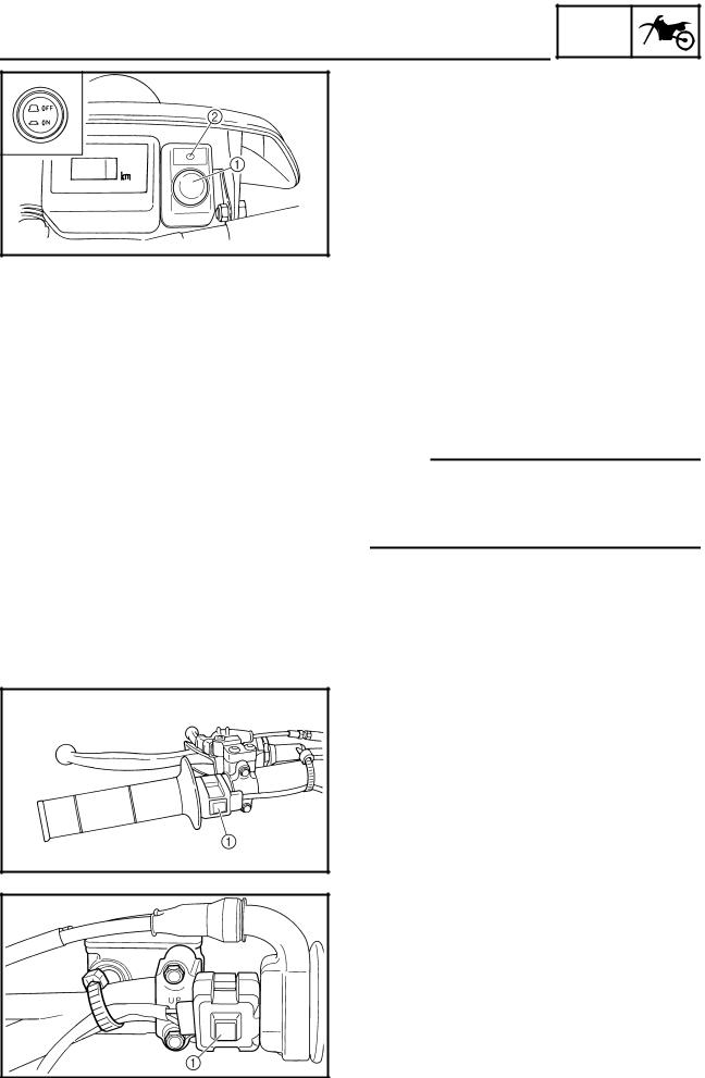
INSTRUMENT AND CONTROL FUNCTIONS EAU10451 EAU52471 EAU49392 Main switch Indicator lights and warning All electrical systems are off. lights EWA16130 WARNING Never push the main switch to “OFF” while the vehicle is moving, otherwise the electrical systems will be switched off, which may result in loss of control or an accident.
-
Page 17: Multi-Function Display
“ON”, or if the warning light remains This warning light comes on when the operator and increase the risk of an on, have a Yamaha dealer check the fuel level drops below approximately accident. electrical circuit.
-
Page 18
INSTRUMENT AND CONTROL FUNCTIONS last set to zero) ton until the display changes after a clock the main switch is pushed to “ON”. Measurement mode: Basic mode a speedometer a distance-compensation tripme- Odometer and tripmeter modes ter (which shows the accumulated Push the “SLCT 2”… -
Page 19
INSTRUMENT AND CONTROL FUNCTIONS push either select button to set the Changing from the basic mode to hours. the measurement mode 3. Push the “RST” button, and the With the odometer selected, push the minute digits will start flashing. “SLCT 1” button and “SLCT 2” button 4. -
Page 20
INSTRUMENT AND CONTROL FUNCTIONS Auto start 1. Push the “SLCT 1” button for at Starting measurement consists of the least two seconds to set the auto following two starts, either of which can start. be selected. Manual start Starting measurement by the rider When the stopwatch is set to auto start, himself operating the button. -
Page 21
Resetting the distance-compensation specified. For further information con- tripmeter cerning the use of this meter, please 1. Check that the stopwatch mea- consult your nearby Yamaha dealer. surement is in operation. Calibrate the distance-compensation 2. Reset the distance-compensation tripmeter as follows. -
Page 22: Handlebar Switches
INSTRUMENT AND CONTROL FUNCTIONS EAU1234B EAU12400 with the starter. See page 5-1 for start- Handlebar switches Dimmer switch “ ” ing instructions prior to starting the en- Set this switch to “ ” for the high gine. Left beam and to “ ”…
-
Page 23: Clutch Lever
INSTRUMENT AND CONTROL FUNCTIONS EAU12820 EAU12871 EAU41264 Clutch lever Shift pedal Brake lever The brake lever is located on the right side of the handlebar. To apply the front brake, pull the lever toward the throttle grip. 1. Clutch lever 1.
-
Page 24: Brake Pedal
INSTRUMENT AND CONTROL FUNCTIONS 3. While holding the lever pushed EAU12941 EAU13182 Brake pedal Fuel tank cap away from the throttle grip, turn the adjusting bolt in direction (a) to in- crease the distance, and in direc- tion (b) to decrease it. Distance between the brake lever and the throttle grip: Minimum (shortest):…
-
Page 25: Fuel
Gasoline is poisonous and can Your Yamaha engine has been de- heat from the engine or the sun cause injury or death. Handle gaso- signed to use premium unleaded gaso- can cause fuel to spill out of the line with care.
-
Page 26: Fuel Tank Breather Hose
INSTRUMENT AND CONTROL FUNCTIONS spark plug life and reduce maintenance EAU41360 EAU13433 Fuel tank breather hose Catalytic converter costs. This model is equipped with a catalytic converter in the exhaust system. EWA10862 WARNING The exhaust system is hot after op- eration.
-
Page 27: Starter Knob
INSTRUMENT AND CONTROL FUNCTIONS converter. EAU53230 EAU13650 Starter knob Kickstarter 1. Starter knob/idle adjusting screw 1. Kickstarter lever Starting a cold engine requires a richer To start the engine, fold out the kick- air-fuel mixture, which is supplied by starter lever, move it down lightly with the starter.
-
Page 28: Steering Lock
INSTRUMENT AND CONTROL FUNCTIONS EAU53100 rection. EAU53200 Steering lock Seat 3. Remove the key. WARNING! Never ride with the key inserted To remove the seat into the steering lock, which Remove the bolts, and then slide the may result in loss of control and seat to the rear and pull upward.
-
Page 29: Install Seat
INSTRUMENT AND CONTROL FUNCTIONS To install the seat EAU52450 Adjusting the front fork 1. Fit the slot in the seat onto the pro- EWA10180 jection on the fuel tank. WARNING Always adjust both fork legs equal- ly, otherwise poor handling and loss of stability may result.
-
Page 30: Front Fork Bleeding
INSTRUMENT AND CONTROL FUNCTIONS each fork leg in direction (b). range. To obtain a precise adjustment, EAU14793 Front fork bleeding it would be advisable to check the num- EWA10200 ber of clicks of each damping force ad- WARNING justing mechanism and to modify the Always bleed both fork legs, other- specifications as necessary.
-
Page 31: Adjusting The Shock Absorber Assembly
Maximum (hard): Spring preload Distance A = 222 mm (8.74 in) Spring preload adjustment should be made by a Yamaha dealer, since this Rebound damping force service requires special tools and tech- To increase the rebound damping force nical skills. The specified settings are and thereby harden the rebound damp- listed below.
-
Page 32
INSTRUMENT AND CONTROL FUNCTIONS sion damping force and thereby soften sion damping, turn the adjusting screw the compression damping, turn the ad- in direction (a). To decrease the com- justing bolt in direction (b). pression damping force and thereby soften the compression damping, turn the adjusting screw in direction (b). -
Page 33: Sidestand
INSTRUMENT AND CONTROL FUNCTIONS visable to check the actual total number absorber assembly to a Yamaha EAU15305 Sidestand of clicks or turns of each damping force dealer for any service. The sidestand is located on the left side adjusting mechanism. This adjustment of the frame.
-
Page 34: Ignition Circuit Cut-Off System
INSTRUMENT AND CONTROL FUNCTIONS Yamaha dealer repair it if it does not EAU52861 Ignition circuit cut-off system function properly. The ignition circuit cut-off system (com- prising the sidestand switch, clutch switch and neutral switch) has the fol- lowing functions. …
-
Page 35
INSTRUMENT AND CONTROL FUNCTIONS WARNING With the engine turned off: 1. Move the sidestand down. If a malfunction is noted, have a Yamaha 2. Make sure that the engine stop switch is set to “ ”. dealer check the system before riding. -
Page 36: For Your Safety — Pre-Operation Checks
• If necessary, add recommended coolant to specified level. 6-12 • Check cooling system for leakage. • Check operation. • If soft or spongy, have Yamaha dealer bleed hydraulic system. • Check brake pads for wear. Front brake • Replace if necessary.
-
Page 37
• Make sure that operation is smooth. • Check throttle grip free play. Throttle grip 6-17, 6-27 • If necessary, have Yamaha dealer adjust throttle grip free play and lubricate cable and grip housing. • Make sure that operation is smooth. Control cables 6-27 •… -
Page 38
• Tighten if necessary. Instruments, lights, signals • Check operation. — and switches • Correct if necessary. • Check operation of ignition circuit cut-off system. Sidestand switch 3-18 • If system is not working correctly, have Yamaha dealer check vehicle. -
Page 39: Operation And Important Riding Points
a lean angle sensor to stop the en- celerate hard when the engine is understand, ask your Yamaha dealer. gine in case of a turnover. In this cold! EWA10271 case, the multi-function display in-…
-
Page 40
Use the kickstarter when the ambient light should come on. If not, ask a temperature is below 10 C (50 F) or Yamaha dealer to check the elec- when at high altitude. trical circuit. 5. When the engine is warm, turn the 3. -
Page 41: Starting A Warm Engine
OPERATION AND IMPORTANT RIDING POINTS EAU52971 EAU16671 Starting a warm engine Shifting If the engine fails to start, push the main Follow the same procedure as for start- switch to “OFF” and give the kickstarter ing a cold engine with the exception 10 to 20 slow kicks at full throttle in or- that the starter is not required when the der to clear the engine of the rich air-fu-…
-
Page 42: Tips For Reducing Fuel Consumption
Do not rev the engine while shifting you are not familiar with vehicle ser- Always use the clutch while down, and avoid high engine vice, have a Yamaha dealer perform changing gears to avoid damag- speeds with no load on the engine. service. …
-
Page 43: Parking
EWA10311 for about 10 to 15 more minutes. period, immediately have a WARNING The motorcycle will now be ready Yamaha dealer check the vehi- Since the engine and exhaust to ride normally. cle. system can become very hot,…
-
Page 44: Periodic Maintenance And Adjustment
– possibly leading to pending on the weather, terrain, geo- that is certified (if applicable). Yamaha death. See page 1-2 for more in- graphical location, and individual use, dealers are trained and equipped to…
-
Page 45: Owner’s Tool Kit
If you do not have the tools or experi- ence required for a particular job, have a Yamaha dealer perform it for you.
-
Page 46: Periodic Maintenance Chart For The Emission Control System
From 7000 km (4200 mi) or 9 months, repeat the maintenance intervals starting from 3000 km (1800 mi) or 3 months. Items marked with an asterisk should be performed by a Yamaha dealer as they require special tools, data and technical skills.
-
Page 47: General Maintenance And Lubrication Chart
PERIODIC MAINTENANCE AND ADJUSTMENT EAU52581 General maintenance and lubrication chart ODOMETER INITIAL READINGS ANNUAL 3000 km 5000 km ITEM CHECKS AND MAINTENANCE JOBS 1000 km CHECK (1800 mi) (3000 mi) (600 mi) or or 3 or 6 1 month months months •…
-
Page 48
PERIODIC MAINTENANCE AND ADJUSTMENT ODOMETER INITIAL READINGS ANNUAL 3000 km 5000 km ITEM CHECKS AND MAINTENANCE JOBS 1000 km CHECK (1800 mi) (3000 mi) (600 mi) or or 3 or 6 1 month months months • Check bearing play and steering for roughness. … -
Page 49
PERIODIC MAINTENANCE AND ADJUSTMENT ODOMETER INITIAL READINGS ANNUAL 3000 km 5000 km ITEM CHECKS AND MAINTENANCE JOBS 1000 km CHECK (1800 mi) (3000 mi) (600 mi) or or 3 or 6 1 month months months • Check hoses for cracks of damage. … -
Page 50: Removing And Installing The Panel
Do not attempt to diagnose 1. Panel A such problems yourself. Instead, have EAU52872 a Yamaha dealer check the vehicle. If the spark plug shows signs of elec- trode erosion and excessive carbon or Panel A other deposits, it should be replaced.
-
Page 51: Check Engine Oil Level
PERIODIC MAINTENANCE AND ADJUSTMENT wire thickness gauge and, if necessary, past finger tight. However, the spark EAU52964 Engine oil and oil filter adjusted to specification. plug should be tightened to the speci- element fied torque as soon as possible. The engine oil level should be checked before each ride.
-
Page 52
PERIODIC MAINTENANCE AND ADJUSTMENT And do not touch the radiator pipe after high-speed operation, otherwise the cooling system is hot and cause burns. Always let the engine oil cool down suffi- ciently before removing the oil tank cap. NOTICE: Do not [EWA16140] operate the vehicle until you know that the engine oil level is… -
Page 53: Change Engine Oil
PERIODIC MAINTENANCE AND ADJUSTMENT 6. Install the engine oil tank cap, and and the engine oil filler cap. then the check bolt and its gasket. To change the engine oil (with or without oil filter element replace- ment) 1. Place the vehicle on a level sur- face.
-
Page 54
PERIODIC MAINTENANCE AND ADJUSTMENT Tightening torques: Engine oil drain bolt (oil tank): Skip steps 8–10 if the oil filter element 20 Nm (2.0 m·kgf, 14 ft·lbf) is not being replaced. Engine oil drain bolt (crank case): 20 Nm (2.0 m·kgf, 14 ft·lbf) 8. -
Page 55: Coolant
If this occurs, Make sure that no foreign mate- have a Yamaha dealer repair the EAUM1295 rial enters the crankcase. vehicle. To check the coolant level …
-
Page 56: Change Coolant
The coolant should be at the bottom of sion. If water has been added to the radiator filler neck. The level will the coolant, have a Yamaha change with variation of engine temper- 1. Coolant drain bolt dealer check the antifreeze con- ature.
-
Page 57: Cleaning The Air Filter Element And Check Hose
9. Start the engine, and then check the vehicle for coolant leakage. If coolant is leaking, have a Yamaha dealer check the cooling system. 1. Holding clip 2. Air filter element 3.
-
Page 58
Recommended oil: erly seated in the air filter case. Yamaha foam air filter oil or other The engine should never be op- quality foam air filter oil erated without the air filter ele- 1. -
Page 59
PERIODIC MAINTENANCE AND ADJUSTMENT 1. Hole 1. Holding clip 1. Air filter check hose 2. Projection 2. Projection 2. If dirt or water is visible, remove 3. Air filter element 8. Close the air filter case cover, and the hose, clean it, and then install 7. -
Page 60: Adjusting The Engine Idling Speed
Yamaha dealer make the adjustment. turn the screw in direction (a). To and, if necessary, have a Yamaha decrease the engine idling speed, dealer adjust it. turn the screw in direction (b).
-
Page 61: Valve Clearance
Tire air pressure (measured on cold from occurring, the valve clearance small area of road contact. Therefore, it tires): must be adjusted by a Yamaha dealer is essential to maintain the tires in good 0–90 kg (0–198 lb): Front: at the intervals specified in the periodic condition at all times and replace them 150 kPa (1.50 kgf/cm…
-
Page 62
Yamaha dealer re- The replacement of all wheel- place the tire immediately. -
Page 63: Spoke Wheels
If any damage is found, have a Yamaha dealer replace the wheel. Do not attempt even the smallest repair to the wheel. A de- formed or cracked wheel must be replaced.
-
Page 64: Checking The Brake Lever Free Play
1. No brake lever free play (b). There should be no free play at the brake lever end. If there is free play, have a Yamaha dealer inspect the brake system. EWA14211 WARNING A soft or spongy feeling in the brake lever can indicate the presence of air in the hydraulic system.
-
Page 65: Checking The Shift Pedal
Brake light switches dent. The operation of the shift pedal should be checked before each ride. If opera- tion is not smooth, have a Yamaha dealer check the vehicle. 1. Rear brake light switch 2. Rear brake light switch adjusting nut…
-
Page 66: Checking The Front And Rear Brake Pads
PERIODIC MAINTENANCE AND ADJUSTMENT EAU22392 peared, have a Yamaha dealer replace EAU22581 Checking the front and rear Checking the brake fluid level the brake pads as a set. brake pads Before riding, check that the brake fluid is above the minimum level mark.
-
Page 67: Changing The Brake Fluid
Rear brake may deteriorate, causing leak- EAU52952 Changing the brake fluid age. Have a Yamaha dealer change the Refill with the same type of brake fluid at the intervals specified in brake fluid. Adding a brake fluid the periodic maintenance and lubrica- other than DOT 4 may result in a tion chart.
-
Page 68: Drive Chain Slack
EAU34317 To adjust the drive chain slack 3. Pull the drive chain up above the Consult a Yamaha dealer before ad- drive chain guard installation bolt justing the drive chain slack. with a force of 50 N (5.0 kgf, 11 1.
-
Page 69: Cleaning And Lubricating The Drive Chain
PERIODIC MAINTENANCE AND ADJUSTMENT nuts to their specified torques. EAU23025 may contain substances that Cleaning and lubricating the could damage the O-rings. [ECA11111] Tightening torques: drive chain Axle nut: The drive chain must be cleaned and 125 Nm (12.5 m·kgf, 90 ft·lbf) lubricated at the intervals specified in Locknut: the periodic maintenance and lubrica-…
-
Page 70: Checking And Lubricating The Cables
Yamaha dealer at the intervals speci- bricated if necessary. ed if necessary. If a cable is damaged fied in the periodic maintenance chart.
-
Page 71: Checking And Lubricating The Brake Pedal
EWA10731 Lithium-soap-based grease WARNING If the sidestand does not move up and down smoothly, have a Yamaha dealer check or repair it. Otherwise, the sidestand could contact the ground and distract the operator, re- sulting in a possible loss of control.
-
Page 72: Lubricating The Swingarm Pivots
The swingarm pivots must be lubricat- intervals specified in the periodic main- ed by a Yamaha dealer at the intervals tenance and lubrication chart. specified in the periodic maintenance and lubrication chart.
-
Page 73: Checking The Steering
If any free This model is equipped with a VRLA the wheel bearings. play can be felt, have a Yamaha (Valve Regulated Lead Acid) battery. dealer check or repair the steering. There is no need to check the electro- lyte or to add distilled water.
-
Page 74: To Store Battery
To charge the battery necessary. Have a Yamaha dealer charge the bat- 3. Fully charge the battery before in- tery as soon as possible if it seems to stallation. NOTICE: When install- have discharged.
-
Page 75: Replacing The Fuse
ECA10650 NOTICE 4. If the fuse immediately blows Take care not to damage the follow- again, have a Yamaha dealer ing parts: check the electrical system. Headlight bulb Do not touch the glass part of the headlight bulb to keep it free 1.
-
Page 76
7. Have a Yamaha dealer adjust the 1. Do not touch the glass part of the bulb. headlight beam if necessary. 1. Remove the headlight cowling to- 1. -
Page 77: Tail/Brake Light
1. Remove the turn signal light lens If the tail/brake light does not come on, by removing the screw. have a Yamaha dealer check it. 1. Turn signal light bulb 3. Insert a new bulb into the socket, push it in, and then turn it clock- wise until it stops.
-
Page 78: Replacing The License Plate Light Bulb
PERIODIC MAINTENANCE AND ADJUSTMENT EAU24313 EAU45224 Replacing the license plate Replacing an auxiliary light light bulb bulb 1. Remove the license plate light unit If the auxiliary light bulb burns out, re- by removing the screws. place it as follows. 1.
-
Page 79: Supporting The Motorcycle
PERIODIC MAINTENANCE AND ADJUSTMENT EAU24350 frame in front of the rear wheel or under Supporting the motorcycle each side of the swingarm. Since this model is not equipped with a centerstand, follow these precautions when removing the front and rear wheel or performing other maintenance requiring the motorcycle to stand up- right.
-
Page 80: Front Wheel
PERIODIC MAINTENANCE AND ADJUSTMENT EAU24360 installing the spacers, be sure Front wheel to install them on the correct side. [ECA17700] EAU49332 2. Lift the wheel up between the fork To remove the front wheel legs. EWA10821 WARNING Make sure that there is enough space To avoid injury, securely support the between the brake pads before install- vehicle so there is no danger of it…
-
Page 81: Rear Wheel
PERIODIC MAINTENANCE AND ADJUSTMENT EAU25080 Tightening torque: Rear wheel Front wheel axle pinch bolt: 21 Nm (2.1 m·kgf, 15 ft·lbf) EAU45183 To remove the rear wheel 8. Push down hard on the handlebar EWA10821 several times to check for proper WARNING fork operation.
-
Page 82
PERIODIC MAINTENANCE AND ADJUSTMENT into the slot in the swingarm. Tightening torques: Make sure that there is enough Axle nut: The drive chain does not need to be space between the brake pads be- 125 Nm (12.5 m·kgf, 90 ft·lbf) disassembled in order to remove and Locknut: fore installing the wheel. -
Page 83: Troubleshooting
The following troubleshooting charts represent quick and easy procedures for checking these vital systems your- self. However, should your motorcycle require any repair, take it to a Yamaha dealer, whose skilled technicians have the necessary tools, experience, and know-how to service the motorcycle properly.
-
Page 84: Troubleshooting Charts
Remove the spark plug and check the electrodes. The engine does not start. Have a Yamaha dealer check the vehicle. Check the compression. 4. Compression The engine does not start. Have a There is compression.
-
Page 85
Start the engine. If the engine overheats again, have a The coolant level Yamaha dealer check and repair the cooling system. is OK. If coolant is not available, tap water can be temporarily used instead, provided that it is changed to the recommended coolant as soon as possible. -
Page 86: Motorcycle Care And Storage
Be ble. Rust and corrosion can develop Cleaning sure to consult a Yamaha dealer for even if high-quality components are ECA10772 advice on what products to use be- NOTICE used.
-
Page 87
MOTORCYCLE CARE AND STORAGE off any detergent residue using Test the product on a small hid- remain well into spring. plenty of water, as it is harmful den part of the windshield to 1. Clean the motorcycle with cold wa- to plastic parts. -
Page 88: Storage
EWA11131 Consult a Yamaha dealer for ad- WARNING ECA10810 NOTICE vice on what products to use. Contaminants on the brakes or tires …
-
Page 89
MOTORCYCLE CARE AND STORAGE stabilizer (if available) to prevent pivoting points of all levers and the fuel tank from rusting and the pedals as well as of the sidestand/ fuel from deteriorating. centerstand. 3. Perform the following steps to pro- 5. -
Page 90: Specifications
SPECIFICATIONS Dimensions: EAU50975 Displacement: With oil filter element replacement: 449 cm 1.00 L (1.06 US qt, 0.88 Imp.qt) Overall length: Bore stroke: Cooling system: 2315 mm (91.1 in) 95.0 63.4 mm (3.74 2.50 in) Overall width: Radiator capacity (including all routes): Compression ratio: 825 mm (32.5 in) 1.04 L (1.10 US qt, 0.92 Imp.qt)
-
Page 91
SPECIFICATIONS Transmission type: Manufacturer/model: Operation: Constant mesh 5-speed BRIDGESTONE/GRITTY-ED04 E Right foot operation Operation: Maximum load: Specified brake fluid: Left foot operation 90 kg (198 lb) DOT 4 Gear ratio: * (Total weight of rider, cargo and accesso- Front suspension: 1st: ries) Type:… -
Page 92
SPECIFICATIONS Tail/brake light: Front turn signal light: 12 V, 10.0 W 2 Rear turn signal light: 12 V, 10.0 W 2 Auxiliary light: 12 V, 5.0 W 1 License plate light: 12 V, 5.0 W 1 Meter lighting: EL (Electroluminescent) Neutral indicator light:… -
Page 93: Consumer Information
Record the vehicle identification num- ber and model label information in the spaces provided below for assistance when ordering spare parts from a Yamaha dealer or for reference in case the vehicle is stolen. VEHICLE IDENTIFICATION NUMBER: 1. Vehicle identification number 1.
-
Page 94
INDEX Air filter element and check hose, Front and rear brake pads, checking..6-23 Panel, removing and installing ….6-7 cleaning ……….6-14 Front fork, adjusting……… 3-14 Parking …………5-5 Auxiliary light bulb, replacing ….6-35 Front fork, bleeding……..3-15 Part locations ……….2-1 Front fork, checking ……… -
Page 95
INDEX Turn signal switch……..3-7 Valve clearance ……..6-18 Vehicle identification number…..9-1 Wheel bearings, checking …….6-30 Wheel (front)……….6-37 Wheel (rear)……….6-38 Wheels………….6-20… -
Page 98
PRINTED ON RECYCLED PAPER PRINTED IN JAPAN 2012.08-0.4×1 !

- Manuals
- Brands
- Yamaha Manuals
- Motorcycle
- WR450FB 2012
- Owner’s service manual
-
Contents
-
Table of Contents
-
Troubleshooting
-
Bookmarks
Related Manuals for Yamaha WR450FB 2012
Summary of Contents for Yamaha WR450FB 2012
-
Page 7: Table Of Contents
TABLE OF CONTENTS GENERAL INFORMATION SPECIFICATIONS PERIODIC CHECKS AND ADJUST- MENTS TUNING CHASIS ENGINE COOLING SYSTEM FUEL SYSTEM ELECTRICAL SYSTEM TROUBLE SHOOTING…
-
Page 206: Engine
ENGINE ENGINE REMOVAL ………………6-1 REMOVING THE ENGINE …………….. 6-4 CLEANING THE SPARK ARRESTER …………6-4 INSTALLING THE ENGINE …………..: ..6-5 INSTALLING THE EXHAUST PIPE AND MUFFLER ……… 6-5 INSTALLING THE SHIFT PEDAL ………….. 6-6 CAMSHAFT …………………. 6-7 REMOVING THE CAMSHAFT …………..
-
Page 244: Clutch
CLUTCH the clutch ,�rg 6-36…
-
Page 245
CLU TCH Remo ving the clutch 10 Nm (1.0 m, kgf, 7.2 ft, lbf) 33 Nm (3.3 m , kgf, 24 ft , lbf) 12 Nm (1.2 m, kgf, 8.7 ft, lbf) 10 Nm (1.0 m. kgf, 7.2 ft· lbf) 10 Nm (1.0 m, kgf, 7.2 ft. -
Page 246
CLUTCH Removing the clutch 10 Nm (1.0 m. kgf, 7.2 ft· lbf) 33 Nm (3.3 m • kgf, 24 ft — lbf) 12 Nm (1.2 m • kgf, 8. 7 ft • lbf) 10 Nm (1.0 m • kgf, 7.2 ft• lbf) Order Job/Parts to remove Remarks… -
Page 247: Removing The Clutch
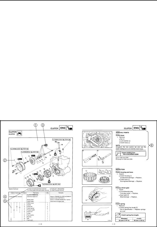
CLUTCH EAS25070 REMOVING THE CLUTCH 1. Straighten the lock washer tab. 2. Remove: • Clutch boss nut «1» • Conical washer «2» • Clutch boss «3» TIP ______________ While holding the clutch boss with the universal clutch holder «4», loosen the clutch boss nut. Universal clutch holder EAS25110 CHECKING THE CLUTCH PLATES…
-
Page 249: Checking The Primary Drive Gear
CLUTCH CHECKING THE PRIMARY DRIVE GEAR 1. Check: • Primary drive gear Damage/wear -+ Replace the primary drive and primary driven gears as a set. Excessive noise during operation -+ Re place the primary drive and primary driven gears as a set. 2.
-
Page 250
CLUTCH 6. Install: 4. Install: • Push rod 2 «1» • Friction plate «1» • Ball «2» • Clutch plate 1 [t=2.0 mm (0.079 in)] «2» • Push rod 1 «3» • Clutch plate 2 [t=1.6 mm (0.063 in)] «3» TIP _____________ _ TIP _____________ _ •… -
Page 254: Kickstater
KICKSTATER 5. Hook: • Torsion spring «1» TIP ____________ _ Turn the torsion spring clockwise and hook into the proper hole «a» in the crankcase. 3. Install: • Spring guide «1» TIP _____________ _ Slide the spring guide into the kick shaft, make sure the groove «a»…
-
Page 256: Shift Shaft
SHIFT SHAFT Removing the shift shaft and stopper lever 10 Nm (1.0 m. kgf, 7.2 ft. lbf) 30 Nm (3.0 m · kgf, 22 ft · lbf) Order Job/Parts to remove Remarks Q’ty Washer Stopper lever spring Segment For installation, reverse the removal proce dure.
-
Page 257: Removing The Segment
SHIFT SHAFT EAS10X3180 REMOVING THE SEGMENT 1. Remove: • Bolt (segment) «1» • Segment «2» TIP _____________ _ Turn the segment counterclockwise until it stops and loosen the bolt. ECA1DX1021 If the segment gets an impact, it may be EAS1DX3181 damaged.
-
Page 258: Installing The Shift Guide And Shift Lever Assembly
SHIFT SHAFT —— 4. Install: • Shift guide bolt «1» EAS1DX3183 INSTALLING THE SHIFT GUIDE AND SHIFT LEVER ASSEMBLY Shift guide bolt 1. Install: 10 Nm (1.0 m·kgf, 7.2 ft·lbf) • Spring «1» • Pawl pin «2» • Pawl «3» To shift lever «4».
-
Page 259: Oil Pump And Balancer Gear
OIL PUMP AND BALANCER GEAR EAS1DX3184 OIL PUMP AND BALANCER GEAR Removing the oil pump and balancer 45 Nm (4.5 m • kgf, 33 ft · lbf) 10 Nm (1.0 m. kgf, 7.2 ft. lbf) 110 Nm (11.0 m • kgf, 80 ft• lbf) 50 Nm (5.0 m •…
-
Page 260
OIL PUMP AND BALANCER GEAR Removing the oil pump and balancer 45 Nm (4.5 m • kgf, 33 ft , lbf) 10 Nm (1.0 m, kgf, 7.2 ft• lbf) lbf) 110 Nm (11.0 m • kgf, 80 ft 50 Nm (5.0 m • kgf, 36 ft , lbf) Order Job/Parts to remove Remarks… -
Page 261
OIL PUMP AND BALANCER GEAR Disassembling the oil pump 2 Nm (0.2 m • kgf, 1.4 ft· lbf) Order Job/Parts to remove Remarks Q’ty Oil pump cover Outer rotor 1 Inner rotor 1 Dowel pin Washer Oil pump drive shaft Rotor housing For assembly, reverse the disassembly pro- cedure. -
Page 263: Assembling The Oil Pump
OIL PUMP AND BALANCER GEAR EAS1DX3187 ASSEM BLING THE OIL PUMP 1. Install: • Oil pump drive shaft «1» • Washer»2″ •• Dowel pin «3» • Inner rotor 1 «4» TIP _____ _____ _ _ _ _ • Apply the engine oil on the oil pump drive shaft and inner rotor 1.
-
Page 264
OIL PUMP AND BALANCER GEAR • Primary drive gear «3» • Conical washer «4»1m1J 5 » • Primary drive gear nut Primary drive gear nut 110 Nm (11.0 m·kgf, 80 fNbf) • Straight key «6» • Balancer «7» • Lock washer «8»1m1J •… -
Page 265: Generator And Starter Clutch
GENERATOR AND STARTER CLUTCH EAS1DX3189 GENERATOR STARTER CLUTCH Removing the generator /jl:. — lbf)I 12 Nm (1.2 m, leg!, 8.7 ft, · · 7 Nm (0.7 m • kgf, 5.1 ft •lbf) 10 Nm (1.0 m. kgf, 7.2 ft lbf) 10 Nm (1.0 m.
-
Page 266
GENERATOR AND STARTER CLUTCH Removing the generator � 12 Nm (1.2 m • kgf, 8.7 ft lbf) 7 Nm (0.7 m, kgf, 5.1 ft ,lbf) 10 Nm (1.0 m. kgf, 7.2 ft lbf) 10 Nm (1.0 m. kgf, 7.2ft,lbf) 10 Nm (1.0 m. kgf, 7.2ft,lbf) 1: s l Y’·—(@ 6 5 Nm (6. -
Page 267: Removing The Generator
GENERATOR AND STARTER CLUTCH EA$1DX3190 2. Check: REMOVING THE GENERATOR • Starter clutch idle gear 1. Remov e : • Starter clutch gear • Generator rotor nut «1» Burrs/chips/roughness/wear� Replace the • Washer defective part (s). 3. Check: • Starter clutch gear Damage/pitting/wear �…
-
Page 268: Installing The Starter Clutch
• Tighten the stator bolt using the T25 bit. • Apply the sealant to the grommet of the AC magneto lead. Starter clutch bolt 16 Nm (1.6 m·kgf, 12 ft-lbf) YAMAHA Bond No. 1215 (Three LOCTITE® Bond No. 1215®) 90890-85505 EAS1DX3193 INSTALLING THE GENERATOR 1.
-
Page 269
GENERATOR AND STARTER CLUTCH 2. Install: • Washer • Generator rotor nut «1» Generator rotor nut 65 Nm (6.5 m·kgf, 47 fMbf) TIP _____________ _._ Tighten the generator rotor nut to 65 Nm (6.5 m·kgf, 47 ft-lbf), loosen and retighten the gener ator rotor nut to 65 Nm (6.5 m·kgf, 47 ft·lbf). -
Page 270
CRANKCASE CRANKCASE EAS25540 Separating the crankcase 12 Nm (1.2 m. kgf, 8.7 ft· lbf) 10 Nm (1.0 m • kgf, 7.2 ft· lbf) 10 Nm (1.0 m, kgf, 7.2 ft• lbf) Job/Parts to remove Remarks Order Q’ty Engine Refer to «ENGINE REMOVAL» on page 6-1. Refer to «CYLINDER AND PISTON»… -
Page 271: Crankcase
CRANKCASE Separating the crankcase 12 Nm (1.2 m • kgf, 8.7 ft• lbf) 10 Nm (1.0 m • kgf, 7.2 ft• lbf) 10 Nm (1.0 m. kgf, 7.2 ft• lbf) Order Job/Parts to remove Remarks Q’ty For installation, reverse the removal proce dure.
-
Page 272
CRANKCASE 6-64… -
Page 273: Disassembling The Crankcase
CRANKCASE EAS25570 DISASSEM BLING THE CRANKCASE 1. Separate: • Right crankcase • Left crankcase TTTTTTTTTTTTTTTTTTTTTTTTTTTTTTTT a. Remove the crankcase bolts, hose guide and clutch cable holder. ··�·············��·��··�········ c. Remove the dowel pins and 0-ring. 2. Remove: • Balancer shaft «1» TIP ______________ _ Remove the balancer shaft with its flat side «a»…
-
Page 274: Assembling The Crankcase
(2) stages, with 1/4 turn each. the screw head. 2. Thoroughly clean all the gasket mating sur faces and crankcase mating surfaces. 3. Apply: • Sealant (onto the crankcase mating surfaces) Yamaha bond No.1215 (Three � ,?’- Bond No.1215®) 90890-85505 3. M6 x80mm 4. M6x60mm 5.
-
Page 275: Crankshaft Assembly And Balancer Shaft
CRANKSHAFT ASSEMBL V AND BALANCER SHAFT EAS25970 CRANKS HAFT ASSEMB LY AND BALANC ER SHAFT Removing the crankshaft assembly and balancer shaft Order Job/Parts to remove Remarks Q’ty Separate. Crankcase Refer to»CRANKCASE» on page 6-62. Balancer shaft Crankshaft assembly For installation, reverse the removal proce dure.
-
Page 276: Crankshaft Assembly And Balancer Shaft
CRANKSHAFT ASSEMBLY AND BALANCER SHAFT EAS26060 EAS1DX3195 REMOVING THE BALANCER SHAFT CHECKING THE CRANKSHAFT ASSEMBLY 1. Measure: 1. Remove: • Crankshaft runout • Balancer shaft «1» Out of specification -, Replace the crank TIP _____________ _ shaft, bearing or both. Remove the balancer shaft with its flat side «a»…
-
Page 277: Installing The Crankshaft Assembly
CRANKSHAFT ASSEMBLY AND BALANCER SHAFT ECA13970 _j _______ _ To avoid scratching the crankshaft and to ease the installation procedure, lubricate the oil seal lips with lithium-soap-based grease and each bearing with engine oil. TIP _____________ _ Hold the connecting rod at top dead center (TDC) with one hand while turning the nut of the crankshaft installer bolt with the other.
-
Page 278
TRANSMISSION EAS26241 TRANSMISSION Removing the transmission, shift drum assembly, and shift forks .._ Q ‘ t y Order Job/Parts to remove Remarks Separate. Crankcase Refer to»CRANKCASE» on page 6-62. Main axle assembly Drive axle assembly Shift drum Shift fork-R Shift fork-C Shift fork-L Collar For installation, reverse the removal proce-… -
Page 279
TRANSMISSION EAS26260 CHECKING THE SHIFT FORKS The following procedure applies to all of the shift forks. 1. Check: • Shift fork cam follower «1» • Shift fork pawl «2» Bends/damage/scoring/wear� Replace the shift fork. EAS1DX3196 CHECKING THE TRANSMISSION 1. Measure: •… -
Page 280
TRANSMISSION • Transmission gear: dogs TIP _____________ _ Cracks/damage/rounded edges -+ Replace • Apply the molybdenum disulfide oil on the in the defective gear (s). ner and end surface of the idler gear and on 4. Check: the inner surface of the sliding gear, then in •… -
Page 281
TRANSMISSION 4. Install: • Collar «1» TIP _____________ _ • Apply the lithium soap base grease on the oil seal lip. • When installing the collar into the crankcase, pay careful attention to the crankcase oil seal lip. 6. Install: •…
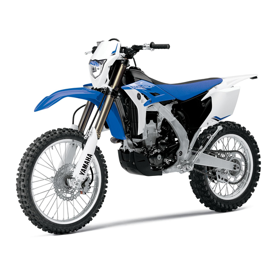
The Yamaha WR450F 2023 is a high-performance off-road motorbike that mixes power, agility, and durability to take on the toughest trails and terrains. The WR450F gives off a sense of strength and toughness with its bold and purposeful design. This bike has a powerful 450cc liquid-cooled four-stroke engine that gives it great torque and speed, making it easy for riders to climb steep hills and get through tricky spots. Its lightweight aluminum frame and advanced suspension system give it great handling and stability, making it easy to control even in tough off-road situations. With features like an electric start, fuel injection, and an engine mapping that can be changed, the WR450F is easy to use and flexible for both casual users and serious racers. The Yamaha WR450F 2023 sets a new standard for off-road bikes. It combines power, agility, and durability to give riders an exciting and memorable ride, whether they are exploring rough trails or taking part in off-road events.
Yamaha WR450F 2023
WARNING:
Operating, servicing and maintaining a passenger vehicle or off-road vehicle can expose you to chemicals including engine exhaust, carbon monoxide, phthalates, and lead, which are known to the State of California to cause cancer and birth defects or other reproductive harm. To minimize exposure, avoid breathing exhaust, do not idle the engine except as necessary, service your vehicle in a well-ventilated area and wear gloves or wash your hands frequently when servicing your vehicle. For more information go to www.P65Warnings.ca.gov/passenger-vehicle
Introduction
Congratulations on your purchase of the Yamaha TT-R50EN. This model is the result of Yamaha’s vast experience in the production of fine sporting, touring, and pacesetting racing machines. It represents the high degree of craftsmanship and reliability that have made Yamaha a leader in these fields. This manual will give you an understanding of the operation, inspection, and basic maintenance of this motorcycle. If you have any questions concerning the operation or maintenance of your motorcycle, please consult a Yamaha dealer. The design and manufacture of this Yamaha motorcycle fully comply with the emissions standards for clean air applicable at the date of manufacture. Yamaha has met these standards without reducing the performance or economy of operation of the motorcycle. To maintain these high standards, it is important that you and your Yamaha dealer pay close attention to the recommended maintenance schedules and operating instructions contained within this manual. Yamaha continually seeks advancements in product design and quality. Therefore, while this manual contains the most current product information available at the time of printing, there may be minor discrepancies between your motorcycle and this manual. If there is any question concerning this manual, please consult Yamaha dealer
WARNING
Please read this manual, the “TIPS AND PRACTICE GUIDE FOR THE OFF-HIGHWAY MOTORCYCLIST” and the “PARENTS, YOUNGSTERS AND OFF-HIGHWAY MOTORCYCLES” booklets carefully and completely before operating or allowing your child to operate this motorcycle. Do not attempt to operate this motorcycle until you have attained adequate knowledge of its controls and operating features and until you have been trained in safe and proper riding techniques. Regular inspections and careful maintenance along with good riding skills, will ensure that you safely enjoy the capabilities and the reliability of this motorcycle.
WARNING
This motorcycle is designed and manufactured for off-road use only. It is illegal to operate this motorcycle on any public street, road or highway. Such use is prohibited by law. This motorcycle complies with almost all state off-highway noise level and spark arrester laws and regulations. Please check your local riding laws and regulations before operating this motorcycle.
AN IMPORTANT SAFETY MESSAGE:
Read this manual, the “PARENTS, YOUNGSTERS AND OFF-HIGHWAY MOTORCYCLES booklet, and the “IPS AND PRACTICE GUDE FOR IHEOFF HIGHWAY MOTORCYCLIST” booklet carefully and completely before operating this motorcycle. Make sure you understand all instructions. Pay close attention to the waning and notice labels on the motorcycle. Never operate a motorcycle without proper training or instruction. Weight of the rider should not exceed 40.0 kg (88 I b).
AN IMPORTANT NOTE TO PARENTS:
This motorcycle is not a toy. Before you let your child ride this motorcycle, you should understand the instructions and warnings in this Owners Manual. Hien be sure your child understands and will follow them. Also read the PARENTS, YOUNGSTERS AND OFF-HIGHWAY MOTORCYCLES and the “TIPS AND PRACTICE GUIDE FOR THE OFF-HIGHWAY MOTORCYCLIST booklets sup- plied with this motorcycle when new or available from your Yamaha dealer. Children differ in skills, physical abilities, and judgment. Some children may not be able to operate a motorcycle safely. Parents should supervise their child’s use of the motorcycle at all times. Parents should permit continued use only if they determine that the child has the ability to operate the motorcycle surely. Your motorcycle is equipped with an adjustable speed limiter. Yamaha recommends that all beginners start off with the speed limiter adjusting screw turned inn to limit the amount of speed available while they lean. the adjusting Screw may De gradually turned out to increase maximum speed as the Detinner becomes more familiar with operating the motorcycle. Parents should decide when to adjust the motorcycle Tor more power as tinier youngsters rising skis improve. Motorcycles are single track vehicles. Their safe use and operation are de- pendent upon the use of proper riding techniques as well as the expertise of the operator. Every operator should know the following requirements before ending this motorcycle.
He or she should:
- Obtain thorough instructions from a competent source on all aspects of motorcycle operation.
- Observe the warnings and maintenance requirements in this Owner’s Manual.
- Obtain qualified training in safe and proper riding techniques.
- Obtain professional technical service as indicated in this Owner’s Manual and/or when made necessary by mechanical conditions.
Safety information
Be a Responsible Owner
As the vehicle s owner, you are responsible for the safe and proper operation of your motorcycle. Motorcycles are single-track vehicles. Their safe use and operation are de pendent upon the use of propounding techniques as well as the expertise of the operator. Every operator should know the following requirements be- Tore riding this motorcycle.
He or she should:
- Obtain thorough instructions from a competent source on all aspects of motorcycle operation.
- Observe the warnings and maintenance requirements in this Owner’s Manual.
- Obtain qualified training in safe and proper riding techniques.
- Obtain professional technical service as indicated in this Owner’s Manual and/or when made necessary by mechanical conditions.
- Never operate a motorcycle without proper training or instruction. Take a training course. Beginners should receive training from a certified instructor. Contact an authorized motorcycle dealer to find out about the training courses nearest you.
Safe Riding
Perform the pre-operation checks each time you use the vehicle to make sure it is in safe operating condition. Failure to inspect or maintain the vehicle properly increases the possibility of an accident or equipment damage.
- This motorcycle is designed for off-road use only, therefore, it is illegal to operate it on public streets, roads, or highways, even a dirt or gravel one. Off-road use on public lands may be legal. Please check local regulations before riding
- This motorcycle is designed to carry the operator only. No pas Singers.
The failure of motorists to detect and recognize motorcycles in tar fic is the predominating cause of automobile motorcycle accidents. Many accidents have been caused by an automobile drivers who did not see the motorcycle. Making yourself conspicuous appears to be very effective in reducing the chance of this type of accident.
Therefore:
Yamaha recommends that all beginners start off with the speed limiter adjusting screw turned inn to limit the amount of speed available while they lean. the adjusting Screw may De gradually turned out to increase maximum speed as the Detinner becomes more familiar with operating the motorcycle. Parents should decide when to adjust the motorcycle Tor more power as tinier youngsters rising skis improve. Motorcycles are single track vehicles. Their safe use and operation are de- pendent upon the use of proper riding techniques as well as the expertise of the operator. Every operator should know the following requirements before ending this motorcycle.
WARNING
wear a brightly colored jacket.
-
- Use extra caution when you are approaching and passing through intersections since in-intersections are the most likely places for motorcycle accidents to occur.
- Ride where other motorists can see you. Avoid ending in another motorcycle blind spot.
- Never maintain a motorcycle without proper knowledge. Contact an authorized motorcycle dealer to inform you on ba- Sic motorcycle maintenance. Certain maintenance can only be carried out by certified staff.
FAQ
1. What is the Yamaha WR450F?
The Yamaha WR450F is a high-performance off-road motorcycle designed for various types of off-road riding, including trail riding, enduro racing, and more.
What type of engine does the Yamaha WR450F have?
The Yamaha WR450F is equipped with a liquid-cooled, 4-stroke, single-cylinder engine.
What is the displacement of the WR450F’s engine?
The displacement of the Yamaha WR450F’s engine is typically around 450cc.
Is the Yamaha WR450F fuel-injected?
Yes, the Yamaha WR450F features fuel injection for improved throttle response and performance.
Yes, the Yamaha WR450F features fuel injection for improved throttle response and performance.
The WR450F usually features high-quality suspension components, including adjustable front forks and a rear shock, designed to handle rough off-road terrain.
Can the Yamaha WR450F be used for racing?
Yes, the Yamaha WR450F is a popular choice for enduro and off-road racing due to its powerful engine and capable chassis.
Is the WR450F street legal?
The street legality of the Yamaha WR450F can vary based on regional regulations and the specific configuration of the bike. Some versions are road-legal, while others are designed solely for off-road use.
How much does the Yamaha WR450F weigh?
The weight of the Yamaha WR450F can vary based on the model year and any modifications, but it’s typically around 250 to 270 pounds (113 to 122 kg) without fuel.
Does the Yamaha WR450F have electric start?
Yes, many recent models of the Yamaha WR450F come equipped with an electric starter in addition to a kickstarter.
Can the Yamaha WR450F be modified for different riding styles?
Yes, the WR450F is a popular platform for modifications, and riders often customize it with aftermarket parts to suit their preferences and riding style.
What is the typical price range for a Yamaha WR450F?
Prices can vary based on the model year and location, but the Yamaha WR450F is typically priced in the range of $9,000 to $10,000 USD for new models.
What are some key competitors to the Yamaha WR450F?
Competitors to the Yamaha WR450F include other off-road motorcycles like the Honda CRF450X, KTM 450 EXC-F, and Beta 450 RR.
Is the WR450F known for reliability?
Yes, Yamaha’s WR series is generally known for its reliability, but proper maintenance and care are still important to ensure longevity.
Does the Yamaha WR450F have different riding modes?
Some modern versions of the Yamaha WR450F come with selectable riding modes that adjust power delivery and throttle response to suit different conditions.
инструкцияYamaha WR450F (2008)

5TJ-28199-45
WR450F
OWNER’S SERVICE MANUAL
MANUEL D’ATELIER DU
PROPRIETAIRE
FAHRER- UND
WARTUNGSHANDBUCH
MANUAL DE SERVICIO
DEL PROPIETARIO
PRINTED IN JAPAN
2007.10-1.6×1 CR
(E,F,G,S)
PRINTED ON RECYCLED PAPER
YAMAHA MOTOR CO., LTD.
2500 SHINGAI IWATA SHIZUOKA JAPAN
2008
2008
Посмотреть инструкция для Yamaha WR450F (2008) бесплатно. Руководство относится к категории мотоциклы, 7 человек(а) дали ему среднюю оценку 9.1. Руководство доступно на следующих языках: английский. У вас есть вопрос о Yamaha WR450F (2008) или вам нужна помощь? Задайте свой вопрос здесь
- TABLE OF CONTENTS
Главная
Не можете найти ответ на свой вопрос в руководстве? Вы можете найти ответ на свой вопрос ниже, в разделе часто задаваемых вопросов о Yamaha WR450F (2008).
Как перевести мили в километры?
1 миля равна 1,609344 километрам, а 1 километр — 0,62137119 милям.
В чем разница между топливом E10 и E5?
В топливе E10 содержится до десяти процентов этанола, в то время как в E5 содержится менее пяти процентов. Соответственно, топливо E10 менее вредит окружающей среде.
Какова рекомендуемая частота замены масляного фильтра в двигателе Yamaha?
В большинстве двигателей масляный фильтр необходимо менять через каждые 6000 километров (около 4000 миль).
Как часто следует менять масло в двигателе Yamaha?
В большинстве двигателей масло необходимо менять через каждые 6000 километров (около 4000 миль).
Как удалить ржавчину с устройства Yamaha мотоцикл?
1. Замочите поржавевшую деталь в уксусе, пока ржавчина не размокнет полностью. 2. Обрабатывайте ржавчину уксусом в течение 24 часов. 3. Удалите ржавчину с помощью металлической щетки или алюминиевой фольги.
Инструкция Yamaha WR450F (2008) доступно в русский?
К сожалению, у нас нет руководства для Yamaha WR450F (2008), доступного в русский. Это руководство доступно в английский.
Не нашли свой вопрос? Задайте свой вопрос здесь
![]()
OWNER’S SERVICE MANUAL
WR450FR
|
LIT-11626-16-43 |
5TJ-28199-10 |


EC010000
WR450FR
OWNER’S SERVICE MANUAL
©2002 by Yamaha Motor Corporation, U.S.A. 1st Edition, October 2002
All rights reserved. Any reprinting or unauthorized use without the written permission of Yamaha Motor Corporation U.S.A. is expressly prohibited.
Printed in Japan
P/N. LIT-11626-16-43
EC020000
INTRODUCTION
Congratulations on your purchase of a Yamaha WR series. This model is the culmination of Yamaha’s vast experience in the production of pacesetting racing machines. It represents the highest grade of craftsmanship and reliability that have made Yamaha a leader.
This manual explains operation, inspection, basic maintenance and tuning of your machine. If you have any questions about this manual or your machine, please contact your Yamaha dealer.
NOTE:
As improvements are made on this model, some data in this manual may become outdated. If you have any questions, please consult your Yamaha dealer.
 WARNING
PLEASE READ THIS MANUAL CAREFULLY AND COMPLETELY BEFORE OPERATING THIS MACHINE. DO NOT ATTEMPT TO OPERATE THIS MACHINE UNTIL YOU HAVE ATTAINED A SATISFACTORY KNOWLEDGE OF ITS CONTROLS AND OPERATING FEATURES AND UNTIL YOU HAVE BEEN TRAINED IN SAFE AND PROPER RIDING TECHNIQUES. REGULAR INSPECTIONS AND CAREFUL MAINTENANCE, ALONG WITH GOOD RIDING SKILLS, WILL ENSURE THAT YOU SAFETY ENJOY THE CAPABILITIES AND THE RELIABILITY OF THIS MACHINE.

IMPORTANT NOTICE
THIS MACHINE IS DESIGNED STRICTLY FOR COMPETITION USE, ONLY ON A CLOSED COURSE. It is illegal for this machine to be operated on any public street, road, or highway. Off-road use on public lands may also be illegal. Please check local regulations before riding.

 SAFETY INFORMATION
1.THIS MACHINE IS TO BE OPERATED BY AN EXPERIENCED RIDER ONLY. Do not attempt to operate this machine at maximum power until you are totally familiar with its characteristics.
2.THIS MACHINE IS DESIGNED TO BE RIDDEN BY THE OPERATOR ONLY. Do not carry passengers on this machine.
3.ALWAYS WEAR PROTECTIVE APPAREL.
When operating this machine, always wear an approved helmet with goggles or a face shield. Also wear heavy boots, gloves, and protective clothing. Always wear proper fitting clothing that will not be caught in any of the moving parts or controls of the machine.
4.ALWAYS MAINTAIN YOUR MACHINE IN PROPER WORKING ORDER.
For safety and reliability, the machine must be properly maintained. Always perform the pre-operation checks indicated in this manual. Correcting a mechanical problem before you ride may prevent an accident.
5.GASOLINE IS HIGHLY FLAMMABLE. Always turn off the engine while refueling. Take care to not spill any gasoline on the engine or exhaust system. Never refuel in the vicinity of an open flame, or while smoking.

6.GASOLINE CAN CAUSE INJURY.
If you should swallow some gasoline, inhale excess gasoline vapors, or allow any gasoline to get into your eyes, contact a doctor immediately. If any gasoline spills onto your skin or clothing, immediately wash skin areas with soap and water, and change your clothes.
7.ONLY OPERATE THE MACHINE IN AN AREA WITH ADEQUATE VENTILATION.
Never start the engine or let it run for any length of time in an enclosed area. Exhaust fumes are poisonous. These fumes contain carbon monoxide, which by itself is odorless and colorless. Carbon monoxide is a dangerous gas which can cause unconsciousness or can be lethal.
8.PARK THE MACHINE CAREFULLY; TURN OFF THE ENGINE.
Always turn off the engine if you are going to leave the machine. Do not park the machine on a slope or soft ground as it may fall over.
9.THE ENGINE, EXHAUST PIPE, MUFFLER, AND OIL TANK WILL BE VERY HOT AFTER THE ENGINE HAS BEEN RUN.
Be careful not to touch them or to allow any clothing item to contact them during inspection or repair.
10.PROPERLY SECURE THE MACHINE BEFORE TRANSPORTING IT.
When transporting the machine in another vehicle, always be sure it is properly secured and in an upright position and that the fuel cock is in the “OFF” position. Otherwise, fuel may leak out of the carburetor or fuel tank.
EC050000
TO THE NEW OWNER
This manual will provide you with a good basic understanding of features, operation, and basic maintenance and inspection items of this machine. Please read this manual carefully and completely before operating your new machine. If you have any questions regarding the operation or maintenance of your machine, please consult your Yamaha dealer.
NOTE:
This manual should be considered a permanent part of this machine and should remain with it even if the machine is subsequently sold.
EC060000
NOTICE
Some data in this manual may become outdated due to improvements made to this model in the future. If there is any question you have regarding this manual or your machine, please consult your Yamaha dealer.
EC070001
F.I.M. MACHINE WEIGHTS:
Weights of machines without fuel
The minimum weights for motocross machines are:
|
for the class 125 cc |
………………….. minimum |
|
88 kg (194 lb) |
|
|
for the class 250 cc ………………….. |
minimum |
|
98 kg (216 lb) |
|
|
for the class 500 cc ………………….. |
minimum |
|
102 kg (225 lb) |
In modifying your machine (e.g., for weight reduction), take note of the above limits of weight.
EC080000
HOW TO USE
THIS MANUAL
EC081000
PARTICULARLY IMPORTANT INFORMATION
The Safety Alert Symbol means ATTENTION! BECOME ALERT! YOUR SAFETY IS INVOLVED!
 WARNING
Failure to follow WARNING instructions could result in severe injury or death to the machine operator, a bystander, or a person inspecting or repairing the machine.

 CAUTION:

A CAUTION indicates special precautions that must be taken to avoid damage to the machine.
NOTE:
A NOTE provides key information to make procedures easier or clearer.
EC082000
FINDING THE REQUIRED PAGE
1.This manual consists of seven chapters; “General Information”, “Specifications”, “Regular inspection and adjustments”, “Engine”, “Chassis”, “Electrical” and “Tuning”.
2.The table of contents is at the beginning of the manual. Look over the general layout of the book before finding then required chapter and item.
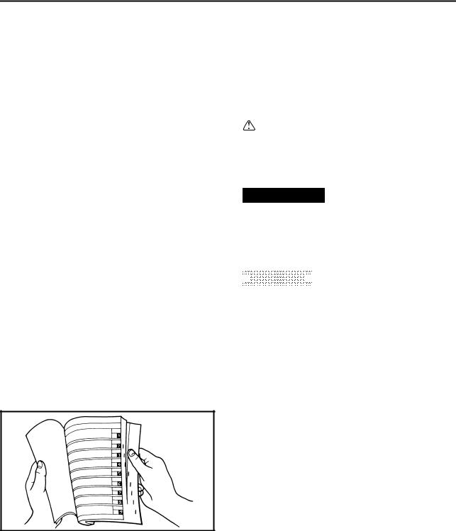
Bend the book at its edge, as shown, to find the required fore edge symbol mark and go to a page for required item and description.
EC083000
MANUAL FORMAT
All of the procedures in this manual are organized in a sequential, step-by-step format. The information has been complied to provide the mechanic with an easy to read, handy reference that contains comprehensive explanations of all disassembly, repair, assembly, and inspection operations.
In this revised format, the condition of a faulty component will precede an arrow symbol and the course of action required will follow the symbol, e.g.,
●Bearings
Pitting/damage → Replace.
EC084002
HOW TO READ DESCRIPTIONS
To help identify parts and clarify procedure steps, there are exploded diagrams at the start of each removal and disassembly section.
1.An easy-to-see exploded diagram 1 is provided for removal and disassembly jobs.
2.Numbers 2 are given in the order of the jobs in the exploded diagram. A number that is enclosed by a circle indicates a disassembly step.
3.An explanation of jobs and notes is presented in an easy-to-read way by the use of symbol marks 3. The meanings of the symbol marks are given on the next page.
4.A job instruction chart 4 accompanies the exploded diagram, providing the order of jobs, names of parts, notes in jobs, etc.
5.Extent of removal 5 is provided in the job instruction chart to save the trouble of an unnecessary removal job.
6.For jobs requiring more information, the step-by-step format supplements 6 are given in addition to the exploded diagram and job instruction chart.
![]()
|
1 |
2 |
|
|
GEN |
SPEC |
|
|
INFO |
||
|
3 |
4 |
|
|
INSP |
ENG |
|
|
ADJ |
||
|
5 |
6 |
|
|
CHAS |
ELEC – |
+ |
|
7 |
8 |
|
|
T U N |
||
|
9 |
0 |
|
|
A |
B |
|
|
T |
||
|
. |
||
|
R |
||
|
. |
||
|
C |
D |
|
|
E |
F |
|
|
E |
M |
|
|
G |
H |
|
|
B |
M |
|
|
I |
J |
|
|
New |
ILLUSTRATED SYMBOLS (Refer to the illustration)
Illustrated symbols 1 to 7 are designed as thumb tabs to indicate the chapter’s number and content.
1 General information
2 Specifications
3 Regular inspection and adjustments
4 Engine
5 Chassis
6 Electrical
7 Tuning
Illustrated symbols 8 to D are used to identify the specifications appearing in the text.
8 With engine mounted
9 Special tool
0 Filling fluid A Lubricant B Tightening
C Specified value, Service limit
D Resistance (Ω), Voltage (V), Electric current (A)
Illustrated symbols E to H in the exploded diagrams indicate grade of lubricant and location of lubrication point.
E Apply engine oil
F Apply molybdenum disulfide oil
G Apply lightweight lithium-soap base grease H Apply molybdenum disulfide grease
Illustrated symbols I to J in the exploded diagrams indicate where to apply a locking agent and where to install new parts.
I Apply locking agent (LOCTITE®)
J Use new one

MEMO
GENERAL INFORMATION
GEN 1 INFO
SPECIFICATIONS
SPEC 2
|
REGULAR |
||||||
|
INSPECTION AND |
||||||
|
INSP |
3 |
|||||
|
ADJUSTMENTS |
||||||
|
ADJ |
||||||
ENGINE
ENG 4
CHASSIS
CHAS 5
– +
ELECTRICAL
ELEC 6
TUNING
TUN 7

EC0A0000
CONTENTS
CHAPTER 1
GENERAL INFORMATION
|
DESCRIPTION …………………………………… |
1-1 |
|
MACHINE IDENTIFICATION ……………….. |
1-2 |
|
IMPORTANT INFORMATION ………………. |
1-3 |
|
CHECKING OF CONNECTION …………….. |
1-6 |
|
SPECIAL TOOLS ……………………………….. |
1-7 |
|
CONTROL FUNCTIONS ……………………. |
1-10 |
|
FUEL ………………………………………………. |
1-14 |
|
STARTING AND BREAK-IN ………………. |
1-15 |
|
TORQUE-CHECK POINTS ………………… |
1-19 |
|
CLEANING AND STORAGE ………………. |
1-20 |
CHAPTER 2
SPECIFICATIONS
|
GENERAL SPECIFICATIONS ……………… |
2-1 |
|
MAINTENANCE SPECIFICATIONS ……… |
2-4 |
|
GENERAL TORQUE |
|
|
SPECIFICATIONS …………………………….. |
2-20 |
|
DEFINITION OF UNITS ……………………… |
2-20 |
|
LUBRICATION DIAGRAMS ……………….. |
2-21 |
|
CABLE ROUTING DIAGRAM …………….. |
2-23 |
CHAPTER 3
REGULAR INSPECTION AND
ADJUSTMENTS
|
MAINTENANCE INTERVALS ………………. |
3-1 |
|
PRE-OPERATION INSPECTION |
|
|
AND MAINTENANCE ………………………….. |
3-4 |
|
ENGINE …………………………………………….. |
3-5 |
|
CHASSIS …………………………………………. |
3-26 |
|
ELECTRICAL …………………………………… |
3-48 |

CHAPTER 4
ENGINE
|
SEAT, FUEL TANK |
|
|
AND SIDE COVERS …………………………… |
4-1 |
|
EXHAUST PIPE AND SILENCER ………… |
4-3 |
|
RADIATOR ………………………………………… |
4-5 |
|
CARBURETOR ………………………………….. |
4-8 |
|
CAMSHAFTS …………………………………… |
4-21 |
|
CYLINDER HEAD …………………………….. |
4-29 |
|
VALVES AND VALVE SPRINGS ……….. |
4-33 |
|
CYLINDER AND PISTON ………………….. |
4-42 |
|
CLUTCH ………………………………………….. |
4-48 |
|
OIL FILTER, WATER PUMP |
|
|
AND CRANKCASE COVER (RIGHT) ….. |
4-55 |
|
BALANCER ……………………………………… |
4-62 |
|
OIL PUMP ……………………………………….. |
4-65 |
|
KICK AXLE AND SHIFT SHAFT ………… |
4-69 |
|
AC MAGNETO |
|
|
AND STARTER CLUTCH ………………….. |
4-76 |
|
ENGINE REMOVAL ………………………….. |
4-83 |
|
CRANKCASE AND CRANKSHAFT ……. |
4-89 |
|
TRANSMISSION, SHIFT CAM |
|
|
AND SHIFT FORK ……………………………. |
4-98 |
CHAPTER 5
CHASSIS
|
FRONT WHEEL AND REAR WHEEL |
……. 5-1 |
|
FRONT BRAKE AND REAR BRAKE ….. |
5-11 |
|
FRONT FORK ………………………………….. |
5-27 |
|
HANDLEBAR …………………………………… |
5-40 |
|
STEERING ………………………………………. |
5-46 |
|
SWINGARM …………………………………….. |
5-52 |
|
REAR SHOCK ABSORBER ………………. |
5-60 |

CHAPTER 6
ELECTRICAL
|
ELECTRICAL COMPONENTS |
|
|
AND WIRING DIAGRAM ……………………… |
6-1 |
|
MAP-CONTROLLED CDI UNIT ……………. |
6-2 |
|
IGNITION SYSTEM …………………………….. |
6-3 |
|
ELECTRIC STARTING SYSTEM ………….. |
6-7 |
|
CHARGING SYSTEM ……………………….. |
6-17 |
|
TPS (THROTTLE POSITION SENSOR) |
|
|
SYSTEM ………………………………………….. |
6-19 |
|
LIGHTING SYSTEM ………………………….. |
6-24 |
|
CHAPTER 7 |
|
|
TUNING |
|
|
ENGINE …………………………………………….. |
7-1 |
|
CHASSIS …………………………………………. |
7-10 |
GEN
DESCRIPTION INFO
EC100000
GENERAL INFORMATION
EC110000
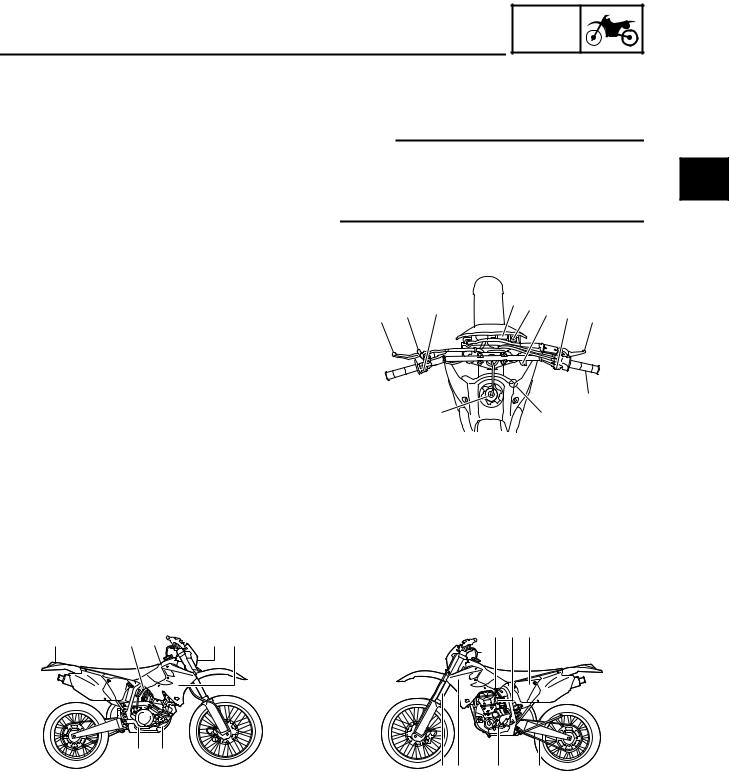
DESCRIPTION
1 Clutch lever
2 Hot starter lever
3 “ENGINE STOP” button
4 Trip meter
5 Main switch
6 Lights switch
7 Start switch
8 Front brake lever
9 Throttle grip
0 Radiator cap A Fuel tank cap B Taillight
C Kickstarter D Fuel tank E Headlight F Radiator
G Coolant drain bolt H Rear brake pedal I Valve joint
J Fuel cock
K Cold starter knob L Air cleaner
M Drive chain N Shift pedal O Oil dipstick P Front fork
NOTE:
●The machine you have purchased may differ slightly from those shown in the following.
●Designs and specifications are subject to change without notice.
9
A 
 0
0
IJKL B C D  E F
E F 

MACHINE IDENTIFICATION
EC120001
GEN
INFO 
MACHINE IDENTIFICATION
There are two significant reasons for knowing the serial number of your machine:
1.When ordering parts, you can give the number to your Yamaha dealer for positive identification of the model you own.
2.If your machine is stolen, the authorities will need the number to search for and identify your machine.
EC121001
VEHICLE IDENTIFICATION NUMBER
The vehicle identification number 1 is
stamped on the right of the steering head pipe.
1
EC123001
ENGINE SERIAL NUMBER
The engine serial number 1 is stamped into 1 the elevated part of the right-side of the
engine.
EC124000
MODEL LABEL
The model label 1 is affixed to the frame under the rider’s seat. This information will be needed to order spare parts.
1 — 2

GEN
IMPORTANT INFORMATION INFO
EC130000
IMPORTANT INFORMATION
EC131010
PREPARATION FOR REMOVAL AND
DISASSEMBLY
1.Remove all dirt, mud, dust, and foreign material before removal and disassembly.
When washing the machine with high pressured water, cover the parts as follows.
●Silencer exhaust port
●Side cover air intake port
●Water pump housing hole at the bottom
●Drain hole on the cylinder head (right side)
●All electrical components
2.Use proper tools and cleaning equipment. Refer to “SPECIAL TOOLS” section.
3.When disassembling the machine, keep mated parts together. They include gears, cylinders, pistons, and other mated parts that have been “mated” through normal wear. Mated parts must be reused as an assembly or replaced.
4.During the machine disassembly, clean all parts and place them in trays in the order of disassembly. This will speed up assembly time and help assure that all parts are correctly reinstalled.
5.Keep away from fire.
1 — 3
IMPORTANT INFORMATION
EC132000
GEN
INFO 
ALL REPLACEMENT PARTS
1.We recommend to use Yamaha genuine parts for all replacements. Use oil and/or grease recommended by Yamaha for assembly and adjustment.
EC133000
GASKETS, OIL SEALS AND O-RINGS
1.All gaskets, oil seals, and O-rings should be replaced when an engine is overhauled. All gasket surfaces, oil seal lips, and O-rings must be cleaned.
2.Properly oil all mating parts and bearings during reassembly. Apply grease to the oil seal lips.
EC134000
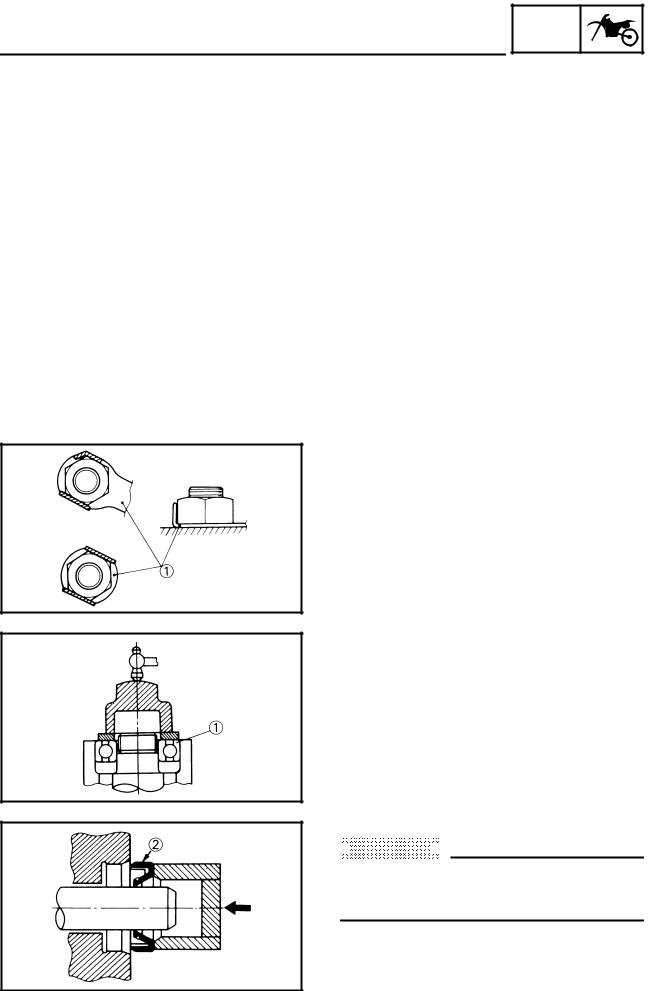
LOCK WASHERS/PLATES AND COTTER PINS
1.All lock washers/plates 1 and cotter pins must be replaced when they are removed. Lock tab(s) should be bent along the bolt or nut flat(s) after the bolt or nut has been properly tightened.
EC135001
BEARINGS AND OIL SEALS
1.Install the bearing(s) 1 and oil seal(s) 2 with their manufacturer’s marks or numbers facing outward. (In other words, the stamped letters must be on the side exposed to view.) When installing oil seal(s), apply a light coating of lightweight lithium base grease to the seal lip(s). Oil the bearings liberally when installing.
 CAUTION:
Do not use compressed air to spin the bearings dry. This causes damage to the bearing surfaces.
1 — 4
![]()
GEN
IMPORTANT INFORMATION INFO
EC136000
CIRCLIPS
1.All circlips should be inspected carefully before reassembly. Always replace piston pin clips after one use. Replace distorted circlips. When installing a circlip 1, make sure that the sharp-edged corner 2 is positioned opposite to the thrust
3 it receives. See the sectional view.
4 Shaft
1 — 5
GEN
CHECKING OF CONNECTION INFO
EC1C0001
CHECKING OF CONNECTION
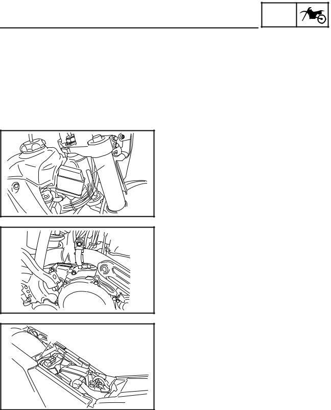
Dealing with stains, rust, moisture, etc. on the connector.
1.Disconnect:
●Connector
2.Dry each terminal with an air blower.
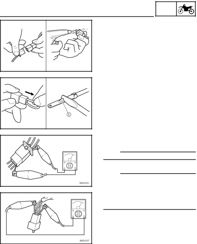
3.Connect and disconnect the connector two or three times.
4.Pull the lead to check that it will not come off.
5.If the terminal comes off, bend up the pin 1 and reinsert the terminal into the connector.
6.Connect:
●Connector
NOTE:
The two connectors “click” together.
7. Check for continuity with a tester.
NOTE:
●If there in no continuity, clean the terminals.
●Be sure to perform the steps 1 to 7 listed above when checking the wireharness.
●For a field remedy, use a contact revitalizer available on the market.
●Use the tester on the connector as shown.
1 — 6
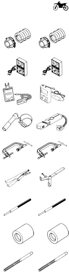
SPECIAL TOOLS
EC140001
SPECIAL TOOLS
GEN
INFO 
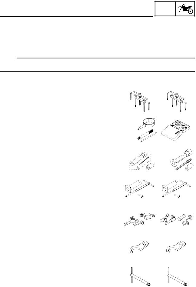
The proper special tools are necessary for complete and accurate tune-up and assembly. Using the correct special tool will help prevent damage caused by the use of improper tools or improvised techniques. The shape and part number used for the special tool differ by country, so two types are provided. Refer to the list provided to avoid errors when placing an order.
NOTE:
●For U.S.A. and Canada, use part number starting with “YM-”, “YU-” or “ACC-”.
●For others, use part number starting with “90890-”.
|
Part number |
Tool name/How to use |
Illustration |
||
|
YU-1135-A, 90890-01135 |
Crankcase separating tool |
YU-1135-A |
90890-01135 |
|
|
These tool is used to remove the crankshaft from |
||||
|
either case. |
||||
|
YU-3097, 90890-01252 |
Dial gauge and stand |
YU-3097 |
90890-01252 |
|
|
YU-1256 |
Stand |
YU-1256 |
||
|
These tools are used to check each part for runout or |
||||
|
bend. |
||||
|
Crankshaft installing tool |
YU-90050 |
90890-01274 |
||
|
YU-90050, 90890-01274 |
Crankshaft installing pot |
YU-90063 |
90890-01275 |
|
|
YM-91044 |
90890-01278 |
|||
|
YU-90050, 90890-01275 |
Crankshaft installing bolt |
|||
|
90890-04081 |
||||
|
YM-91044, 90890-04081 |
Spacer (crankshaft installer) |
|||
|
YU-90063, 90890-01278 |
Adapter (M12) |
|||
|
These tools are used to install the crankshaft. |
||||
|
YU-1304, 90890-01304 |
Piston pin puller |
YU-1304 |
90890-01304 |
|
|
This tool is used to remove the piston pin. |
||||
|
YU-24460-01, 90890-01325 |
Radiator cap tester |
YU-24460-01 |
90890-01325 |
|
|
YU-33984, 90890-01352 |
Adapter |
YU-33984 |
90890-01352 |
|
|
These tools are used for checking the cooling sys- |
||||
|
tem. |
||||
|
YU-33975, 90890-01403 |
Ring nut wrench |
YU-33975 |
90890-01403 |
|
|
This tool is used when tighten the steering ring nut to |
||||
|
specification. |
||||
|
YM-1423, 90890-01423 |
Damper rod holder |
YM-1423 |
90890-01423 |
|
|
Use this tool to remove and install the damper rod. |
||||
1 — 7
|
SPECIAL TOOLS |
GEN |
||||||
|
INFO |
|||||||
|
Part number |
Tool name/How to use |
Illustration |
|||||
|
YM-01442, 90890-01442 |
Fork seal driver |
YM-01442 |
90890-01442 |
||||
|
This tool is used when install the fork oil seal. |
|||||||
|
YU-3112-C, 90890-03112 |
Yamaha pocket tester |
YU-3112-C |
90890-03112 |
||||
|
Use this tool to inspect the coil resistance, output |
|||||||
|
voltage and amperage. |
|||||||
|
YU-8036-B |
Inductive tachometer |
YU-8036-B |
90890-03113 |
||||
|
90890-03113 |
Engine tachometer |
||||||
|
This tool is needed for observing engine rpm. |
|||||||
|
YM-33277-A, 90890-03141 |
Timing light |
YM-33277-A |
90890-03141 |
||||
|
This tool is necessary for checking ignition timing. |
|||||||
|
YM-4019, 90890-04019 |
Valve spring compressor |
YM-4019 |
90890-04019 |
||||
|
This tool is needed to remove and install the valve |
|||||||
|
assemblies. |
|||||||
|
YM-91042, 90890-04086 |
Clutch holding tool |
YM-91042 |
90890-04086 |
||||
|
This tool is used to hold the clutch when removing or |
|||||||
|
installing the clutch boss securing nut. |
|||||||
|
YM-4116, 90890-04116 |
Valve guide remover |
YM-4116 |
90890-04116 |
||||
|
YM-4097, 90890-04097 |
Intake 4.5 mm (0.18 in) |
YM-4097 |
90890-04097 |
||||
|
Exhaust 5.0 mm (0.20 in) |
|||||||
|
This tool is needed to remove and install the valve |
|||||||
|
guide. |
|||||||
|
YM-4117, 90890-04117 |
Valve guide installer |
YM-4117 |
90890-04117 |
||||
|
YM-4098, 90890-04098 |
Intake |
YM-4098 |
90890-04098 |
||||
|
Exhaust |
|||||||
|
This tool is needed to install the valve guide. |
|||||||
|
YM-4118, 90890-04118 |
Valve guide reamer |
YM-4118 |
90890-04118 |
||||
|
YM-4099, 90890-04099 |
Intake 4.5 mm (0.18 in) |
YM-4099 |
90890-04099 |
||||
|
Exhaust 5.0 mm (0.20 in) |
|||||||
|
This tool is needed to rebore the new valve guide. |
|||||||
1 — 8

|
SPECIAL TOOLS |
GEN |
||||||
|
INFO |
|||||||
|
Part number |
Tool name/How to use |
Illustration |
|||||
|
YM-04141, 90890-04141 |
Rotor puller |
YM-04141 |
90890-04141 |
||||
|
This tool is used to remove the flywheel magneto. |
|||||||
|
YM-34487 |
Dynamic spark tester |
YM-34487 |
90890-06754 |
||||
|
90890-06754 |
Ignition checker |
||||||
|
This instrument is necessary for checking the ignition |
|||||||
|
system components. |
|||||||
|
ACC-QUICK-GS-KT |
Quick gasket |
ACC-QUICK-GS-KT |
90890-85505 |
||||
|
90890-85505 |
YAMAHA Bond No. 1215 |
||||||
|
This sealant (Bond) is used for crankcase mating |
|||||||
|
surface, etc. |
|||||||
1 — 9
CONTROL FUNCTIONS
EC150000
GEN
INFO 
CONTROL FUNCTIONS
MAIN SWITCH
Functions of the respective switch positions are as follows:
ON:
The engine can be started only at this position. OFF:
All electrical circuits are switched off.
Main switch indicator light
The main switch 1 is equipped with an indicator light 2 to avoid forgetting to turn it off. This light functions as follows.
●It lights up with the main switch “ON”.
●It goes out when the engine increases its speed after being started.
●It lights up again when the engine is stopped.
NOTE:
If the indicator light will not light up with the main switch “ON”, it shows a lack of the battery voltage. Recharge the battery. If the engine is kick started, turn off the light switch.
EC151000
“ENGINE STOP” BUTTON
The “ENGINE STOP” button 1 is located on the left handlebar. Continue pushing the “ENGINE STOP” button till the engine comes to a stop.
START SWITCH
The start switch 1 is located on the right handlebar. Push this switch to crank the engine with the starter.
1 — 10
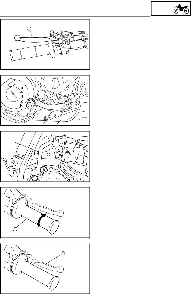
GEN
CONTROL FUNCTIONS INFO
EC152000
CLUTCH LEVER
The clutch lever 1 is located on the left handlebar; it disengages or engages the clutch. Pull the clutch lever to the handlebar to disengage the clutch, and release the lever to engage the clutch. The lever should be pulled rapidly and released slowly for smooth starts.
EC153000
SHIFT PEDAL
The gear ratios of the constant-mesh 5 speed transmission are ideally spaced. The gears can be shifted by using the shift pedal 1 on the left side of the engine.
EC154000
KICKSTARTER
Rotate the kickstarter 1 away from the engine. Push the starter down lightly with your foot until the gears engage, then kick smoothly and forcefully to start the engine. This model has a primary kickstarter so the engine can be started in any gear if the clutch is disengaged. In normal practices, however, shift to neutral before starting.
EC155001
THROTTLE GRIP
The throttle grip 1 is located on the right handlebar; it accelerates or decelerates the engine. For acceleration, turn the grip toward you; for deceleration, turn it away from you.
EC156000
FRONT BRAKE LEVER
The front brake lever 1 is located on the right handlebar. Pull it toward the handlebar to activate the front brake.
1 — 11
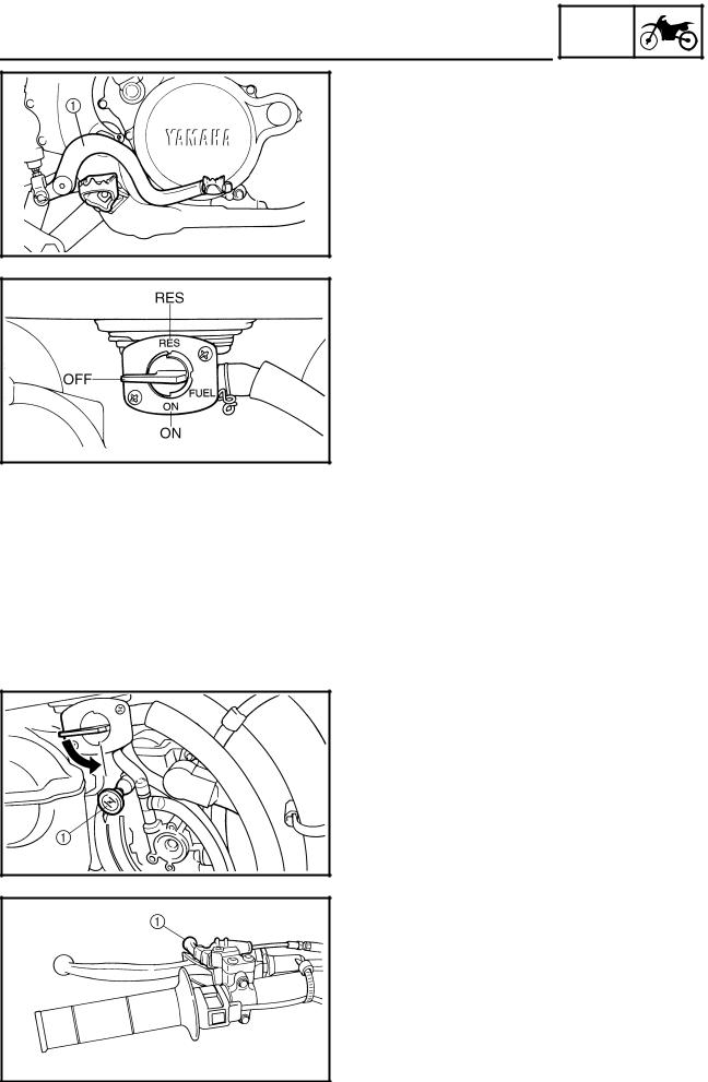
GEN
CONTROL FUNCTIONS INFO
EC157000
REAR BRAKE PEDAL
The rear brake pedal 1 is located on the right side of the machine. Press down on the brake pedal to activate the rear brake.
FUEL COCK
The fuel cock supplies fuel from the tank to carburetor and also filters the fuel. The fuel cock has three positions:
OFF:With the lever in this position fuel will not flow. Always return the lever to this position when the engine is not running.
ON: With the lever in this position fuel flows to the carburetor. Normal riding is done with the lever in this position.
RES:With the lever in this position fuel flows to the carburetor from the reserve section of the fuel tank after the main supply of the fuel has been depleted. Normal riding is possible with the lever is in this position, but it is recommended to add fuel as soon as possible.
COLD STARTER KNOB
When cold, the engine requires a richer air-fuel mixture for starting. A separate starter circuit, which is controlled by the cold starter knob 1, supplies this mixture. Pull the cold starter knob out to open the circuit for starting. When the engine has warmed up, push it in to close the circuit.
HOT STARTER LEVER
The hot starter lever 1 is used when starting a warm engine.
Use the hot starter lever when starting the engine again immediately after it was stopped (the engine is still warm). Pulling the hot starter lever injects secondary air to thin the air-fuel mixture temporarily, allowing the engine to be started more easily.
1 — 12
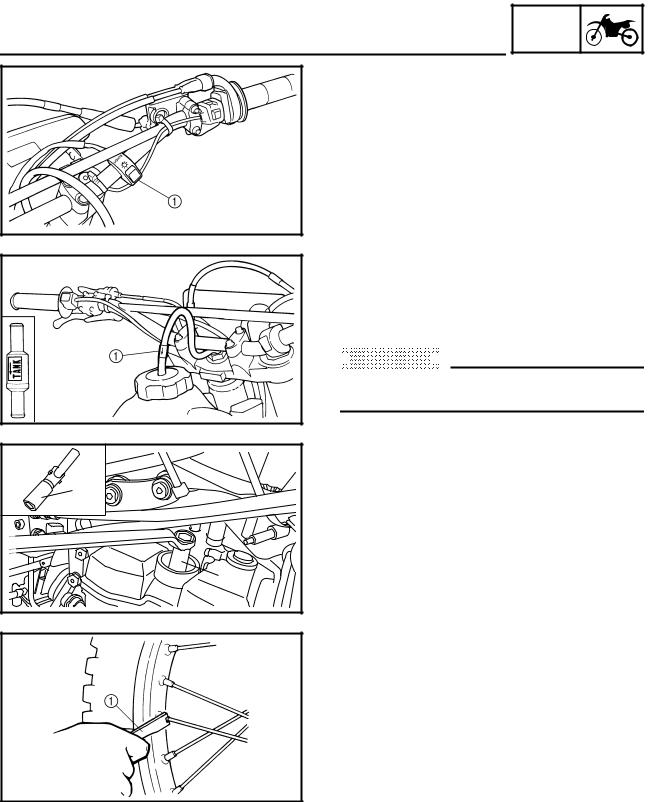
GEN
CONTROL FUNCTIONS INFO
LIGHTS SWITCH
The lights switch 1 is located on the handlebar.
EC15F000
VALVE JOINT
This valve joint 1 prevents fuel from flowing out and is installed to the fuel tank breather hose.
 CAUTION:
In this installation, make sure the arrow faces the fuel tank and also downward.
SPARK PLUG WRENCH
This spark plug wrench 1 is used to remove and install the spark plug.
NIPPLE WRENCH
This nipple wrench 1 is used to tighten the spoke.
1 — 13
Always use the recommended fuel as stated below. Also, be sure to use new gasoline the day of a race.
Recommended fuel: Except for ZA:
Premium unleaded gasoline only with a research octane number of 95 or higher.
For ZA:
Premium gasoline
 CAUTION:
Use only unleaded gasoline. The use of leaded gasoline will cause severe damage to the engine internal parts such as valves, piston rings, and exhaust system, etc.
NOTE:
If knocking or pinging occurs, use a different brand of gasoline or higher octane grade.
 WARNING
●For refueling, be sure to stop the engine and use enough care not to spill any fuel. Also be sure to avoid refueling close to a fire.
●Refuel after the engine, exhaust pipe, etc. have cooled off.
1 — 14
![]()
GEN
STARTING AND BREAK-IN INFO
STARTING AND BREAK-IN
 WARNING
Never start or run the engine in a closed area. The exhaust fumes are poisonous; they can cause loss of consciousness and death in a very short time. Always operate the machine in a well-ventilated area.
 CAUTION:
●The carburetor on this machine has a built-in accelerator pump. Therefore, when starting the engine, do not operate the throttle or the spark plug will foul.
●Unlike a two-stroke engine, this engine cannot be kick started when the throttle is open because the kickstarter may kick back. Also, if the throttle is open the air/ fuel mixture may be too lean for the engine to start.
●Before starting the machine, perform the checks in the pre-operation check list.
AIR FILTER MAINTENANCE
According to “AIR FILTER CLEANING” section in the CHAPTER 3, apply the foam-air-filter oil or its equivalent to the element. (Excess oil in the element may adversely affect engine starting.)
STARTING A COLD ENGINE
NOTE:
This model is equipped with an ignition circuit cut-off system. The engine can be started under the following conditions.
●When the transmission is in neutral.
●When the clutch is disengaged with the transmission in any position. However, it is recommended to shift into neutral before starting the engine.
1.Inspect the coolant level.
2.Turn the fuel cock to “ON”.
3.Push the main switch to “ON”.
4.Shift the transmission into neutral.
5.Fully open the cold starter knob 1.
6.Start the engine by pushing the start switch or by kicking the kickstarter.
1 — 15

GEN
STARTING AND BREAK-IN INFO
NOTE:
If the engine fails to start by pushing the start switch, release the switch, wait a few seconds, and then try again. Each starting attempt should be as short as possible to preserve the battery. Do not crank the engine more than 10 seconds on any one attempt. If the engine does not start with the starter motor, try using the kickstarter.
 WARNING
●If the starter motor will not turn when pushing the start switch, stop pushing it immediately and kick start the engine in order to avoid the load on the motor.
●Do not open the throttle while kicking the kickstarter. Otherwise, the kickstarter may kick back.
7.Return the cold starter knob to its original position and run the engine at 3,000 ~ 5,000 r/min for 1 or 2 minutes.
NOTE:
Since this model is equipped with an accelerator pump, if the engine is raced (the throttle opened and closed), the air/fuel mixture will be too rich and the engine may stall. Also unlike a two-stroke engine, this model can idle.
 CAUTION:
Do not warm up the engine for extended periods of time.
1 — 16

GEN
STARTING AND BREAK-IN INFO
STARTING A WARM ENGINE
Do not operate the cold starter knob and throttle. Pull the hot starter lever 1 and start the engine by pushing the start switch or by kicking the kickstarter forcefully with a firm stroke. As soon as the engine starts, release the hot starter lever to close the air passage.
Restarting an engine after a fall
Pull the hot starter lever and start the engine. As soon as the engine starts, release the hot starter lever to close the air passage.
The engine fails to start
Pull the hot starter lever all the way out and while holding the lever, kick the kickstarter 10 to 20 times to clear the engine.
Then, restart the engine.
Refer to “Restarting an engine after a fall”.
|
Throttle |
Cold |
Hot |
|||
|
grip oper- |
starter |
starter |
|||
|
ation* |
knob |
lever |
|||
|
Air temperature = less than |
Open 3 |
ON |
OFF |
||
|
engine |
5 ˚C (41 ˚F) |
or 4 times |
|||
|
Air temperature = more |
None |
ON |
OFF |
||
|
than 5 ˚C (41 ˚F) |
|||||
|
cold |
|||||
|
Air temperature (normal tem- |
|||||
|
a |
|||||
|
perature) = between 5 ˚C |
None |
ON/OFF |
OFF |
||
|
Starting |
|||||
|
(41 ˚F) and 25 ˚C (77 ˚F) |
|||||
|
Air temperature = more |
None |
OFF |
OFF |
||
|
than 25 ˚C (77 ˚F) |
|||||
|
Starting an engine after a long |
None |
ON |
OFF |
||
|
period of time |
|||||
|
Restarting a warm engine |
None |
OFF |
ON |
||
|
Restarting an engine after a fall |
None |
OFF |
ON |
||
* Operate the throttle grip before kick starting.
 CAUTION:
Observe the following break-in procedures during initial operation to ensure optimum performance and avoid engine damage.
1 — 17

GEN
STARTING AND BREAK-IN INFO
BREAK-IN PROCEDURES
1.Before starting the engine, fill the fuel tank with the fuel.
2.Perform the pre-operation checks on the machine.
3.Start and warm up the engine. Check the idle speed, and check the operation of the controls and the “ENGINE STOP” button. Then, restart the engine and check its operation within no more than 5 minutes after it is restarted.
4.Operate the machine in the lower gears at moderate throttle openings for five to eight minutes.
5.Check how the engine runs when the machine is ridden with the throttle 1/4 to 1/2 open (low to medium speed) for about one hour.
6.Restart the engine and check the operation of the machine throughout its entire operating range. Restart the machine and operate it for about 10 to 15 more minutes. The machine will now be ready to race.
 CAUTION:
●After the break-in or before each race, you must check the entire machine for loose fittings and fasteners as per “TORQUE-CHECK POINTS”.
Tighten all such fasteners as required.
●When any of the following parts have been replaced, they must be broken in. CYLINDER AND CRANKSHAFT:
About one hour of break-in operation is necessary.
PISTON, RING, VALVES, CAMSHAFTS AND GEARS:
These parts require about 30 minutes of break-in operation at half-throttle or less. Observe the condition of the engine carefully during operation.
1 — 18

TORQUE-CHECK POINTS
TORQUE-CHECK POINTS
GEN  INFO
INFO 

|
Frame construction |
Frame to rear frame |
|||
|
Combined seat and tank |
Fuel tank to frame |
|||
|
Exhaust system |
Silencer to rear frame |
|||
|
Engine mounting |
Frame to engine |
|||
|
Engine bracket to engine |
||||
|
Engine bracket to frame |
||||
|
Steering |
Steering shaft to |
Steering shaft to frame |
||
|
handlebar |
Steering shaft to handle crown |
|||
|
Handle crown to handlebar |
||||
|
Suspension |
Front |
Steering shaft to front |
Front fork to handle crown |
|
|
fork |
Front fork to under bracket |
|||
|
Rear |
For link type |
Assembly of links |
||
|
Link to frame |
||||
|
Link to shock absorber |
||||
|
Link to swingarm |
||||
|
Rear |
Installation of shock |
Shock absorber to frame |
||
|
absorber |
||||
|
Rear |
Installation of swing- |
Tightening of pivot shaft |
||
|
arm |
||||
|
Wheel |
Installation of wheel |
Front |
Tightening of front axle |
|
|
Tightening of axle holder |
||||
|
Rear |
Tightening of rear axle |
|||
|
Wheel to sprocket |
||||
|
Brake |
Front |
Caliper to front fork |
||
|
Brake disc to wheel |
||||
|
Tightening of union bolt |
||||
|
Master cylinder to handlebar |
||||
|
Tightening of air bleeder |
||||
|
Rear |
Brake pedal to frame |
|||
|
Brake disc to wheel |
||||
|
Tightening of union bolt |
||||
|
Master cylinder to frame |
||||
|
Tightening of air bleeder |
||||
|
Fuel system |
Fuel tank to fuel cock |
|||
|
Lubrication system |
Tightening of oil hose clamp |
NOTE:
Concerning the tightening torque, refer to “MAINTENANCE SPECIFICATIONS” section
in the CHAPTER 2.
1 — 19

CLEANING AND STORAGE
EC1B0000
GEN  INFO
INFO 

CLEANING AND STORAGE
EC1B1000
CLEANING
Frequent cleaning of your machine will enhance its appearance, maintain good overall performance, and extend the life of many components.
1.Before washing the machine, block off the end of the exhaust pipe to prevent water from entering. A plastic bag secured with a rubber band may be used for this purpose.
2.If the engine is excessively greasy, apply some degreaser to it with a paint brush. Do not apply degreaser to the chain, sprockets, or wheel axles.
3.Rinse the dirt and degreaser off with a garden hose; use only enough pressure to do the job.
 CAUTION:
Excessive hose pressure may cause water seepage and contamination of wheel bearings, front forks, brakes and transmission seals. Many expensive repair bills have resulted from improper high pressure detergent applications such as those available in coin-operated car washers.
4.After the majority of the dirt has been hosed off, wash all surfaces with warm water and a mild detergent. Use an old toothbrush to clean hard-to-reach places.
5.Rinse the machine off immediately with clean water, and dry all surfaces with a soft towel or cloth.
6.Immediately after washing, remove excess water from the chain with a paper towel and lubricate the chain to prevent rust.
7.Clean the seat with a vinyl upholstery cleaner to keep the cover pliable and glossy.
1 — 20

GEN
CLEANING AND STORAGE INFO
8.Automotive wax may be applied to all painted or chromed surfaces. Avoid combination cleaner-waxes, as they may contain abrasives.
9.After completing the above, start the engine and allow it to idle for several minutes.
EC1B2001
STORAGE
If your machine is to be stored for 60 days or more, some preventive measures must be taken to avoid deterioration. After cleaning the machine thoroughly, prepare it for storage as follows:
1.Drain the fuel tank, fuel lines, and the carburetor float bowl.
2.Remove the spark plug, pour a tablespoon of SAE 10W-30 motor oil in the spark plug hole, and reinstall the plug. With the engine stop switch pushed in, kick the engine over several times to coat the cylinder walls with oil.
3.Remove the drive chain, clean it thoroughly with solvent, and lubricate it. Reinstall the chain or store it in a plastic bag tied to the frame.
4.Lubricate all control cables.
5.Block the frame up to raise the wheels off the ground.
6.Tie a plastic bag over the exhaust pipe outlet to prevent moisture from entering.
7.If the machine is to be stored in a humid or salt-air environment, coat all exposed metal surfaces with a film of light oil. Do not apply oil to rubber parts or the seat cover.
NOTE:
Make any necessary repairs before the machine is stored.
1 — 21

GENERAL SPECIFICATIONS SPEC
EC200000
SPECIFICATIONS
EC211000
GENERAL SPECIFICATIONS
|
Model name: |
WR450FR (USA) |
||||||||||||||||||
|
WR450F (EUROPE) |
|||||||||||||||||||
|
WR450F(R) (CDN, AUS, NZ, ZA) |
|||||||||||||||||||
|
Model code number: |
5TJ1 (USA) |
||||||||||||||||||
|
5TJ2 (EUROPE) |
|||||||||||||||||||
|
5TJ4 (CDN, AUS, NZ, ZA) |
|||||||||||||||||||
|
Dimensions: |
|||||||||||||||||||
|
Overall length |
2,171 mm (85.5 in) |
||||||||||||||||||
|
Overall width |
827 mm (32.6 in) |
||||||||||||||||||
|
Overall height |
1,303 mm (51.3 in) |
||||||||||||||||||
|
Seat height |
998 mm (39.3 in) |
||||||||||||||||||
|
Wheelbase |
1,485 mm (58.5 in) |
||||||||||||||||||
|
Minimum ground clearance |
371 mm (14.6 in) |
||||||||||||||||||
|
Basic weight: |
|||||||||||||||||||
|
With oil and full fuel tank |
122 kg (269 lb) |
||||||||||||||||||
|
Engine: |
|||||||||||||||||||
|
Engine type |
Liquid cooled 4-stroke, DOHC |
||||||||||||||||||
|
Cylinder arrangement |
Single cylinder, forward inclined |
||||||||||||||||||
|
Displacement |
449 cm3 (15.8 Imp oz, 15.2 US oz) |
||||||||||||||||||
|
Bore × stroke |
95.0 × 63.4 mm (3.74 × 2.50 in) |
||||||||||||||||||
|
Compression ratio |
12.5 : 1 |
||||||||||||||||||
|
Starting system |
Kick and electric starter |
||||||||||||||||||
|
Lubrication system: |
Dry sump |
||||||||||||||||||
|
Oil type or grade: |
|||||||||||||||||||
|
Engine oil |
(For USA and CDN) |
||||||||||||||||||
|
At 5 ˚C (40 ˚F) or higher Å |
|||||||||||||||||||
|
Yamalube 4 (20W-40) or SAE 20W-40 type SG |
|||||||||||||||||||
|
motor oil (Non-Friction modified) |
|||||||||||||||||||
|
At 15 ˚C (60 ˚F) or lower ı |
|||||||||||||||||||
|
Yamalube 4 (10W-30) or SAE 10W-30 type SG |
|||||||||||||||||||
|
motor oil (Non-Friction modified) and/or |
|||||||||||||||||||
|
Yamalube 4-R (15W-50) (Non-Friction modi- |
|||||||||||||||||||
|
fied) |
|||||||||||||||||||
|
(Except for USA and CDN) |
|||||||||||||||||||
|
Temp. |
°C |
||||||||||||||||||
|
API “SG” or higher grade |
|||||||||||||||||||
|
-20 |
-10 |
0 |
10 |
20 |
30 |
40 |
50 |
||||||||||||
|
10W-30 |
|||||||||||||||||||
|
10W-40 |
|||||||||||||||||||
|
15W-40 |
|||||||||||||||||||
|
20W-40 |
|||||||||||||||||||
|
20W-50 |
|||||||||||||||||||
|
-4 |
14 |
30 |
50 |
68 |
86 |
104 |
122 °F |
||||||||||||
|
2 — 1 |

|
GENERAL SPECIFICATIONS |
SPEC |
||||
|
Oil capacity: |
|||||
|
Engine oil |
|||||
|
Periodic oil change |
1.0 L (0.88 Imp qt, 1.06 US qt) |
||||
|
With oil filter replacement |
1.1 L (0.97 Imp qt, 1.16 US qt) |
||||
|
Total amount |
1.2 L (1.06 Imp qt, 1.27 US qt) |
||||
|
Coolant capacity (including all routes): |
1.6 L (1.41 Imp qt, 1.69 US qt) |
||||
|
Air filter: |
Wet type element |
||||
|
Fuel: |
|||||
|
Type |
Premium unleaded gasoline only with a research |
||||
|
octane number of 95 or higher.(Except for ZA) |
|||||
|
Premium gasoline (For ZA) |
|||||
|
Tank capacity |
10 L (2.2 Imp gal, 2.64 US gal) |
||||
|
Reserve |
1.2 L (0.26 Imp gal, 0.32 US gal) |
||||
|
Carburetor: |
|||||
|
Type |
FCR MX39 |
||||
|
Manufacturer |
KEIHIN |
||||
|
Spark plug: |
|||||
|
Type/manufacturer |
CR8E/NGK (resistance type) |
||||
|
Gap |
0.7 ~ 0.8 mm (0.028 ~ 0.031 in) |
||||
|
Clutch type: |
Wet, multiple-disc |
||||
|
Transmission: |
|||||
|
Primary reduction system |
Gear |
||||
|
Primary reduction ratio |
62/22 (2.818) |
||||
|
Secondary reduction system |
Chain drive |
||||
|
Secondary reduction ratio |
50/14 (3.571) |
||||
|
Transmission type |
Constant mesh, 5-speed |
||||
|
Operation |
Left foot operation |
||||
|
Gear ratio: 1st |
29/12 (2.416) |
||||
|
2nd |
26/15 (1.733) |
||||
|
3rd |
21/16 (1.312) |
||||
|
4th |
21/20 (1.050) |
||||
|
5th |
21/25 (0.840) |
||||
|
Chassis: |
|||||
|
Frame type |
Semi double cradle |
||||
|
Caster angle |
27.2˚ |
||||
|
Trail |
118 mm (4.65 in) |
||||
|
Tire: |
|||||
|
Type |
With tube |
||||
|
Size (front) |
80/100-21 51M (USA, CDN, ZA) |
||||
|
90/90-21 54R (EUROPE, AUS, NZ) |
|||||
|
Size (rear) |
110/100-18 64M (USA, CDN, ZA) |
||||
|
130/90-18 69R (EUROPE, AUS, NZ) |
|||||
|
Tire pressure (front and rear) |
100 kPa (1.0 kgf/cm2, 15 psi) |
2 — 2

|
GENERAL SPECIFICATIONS |
SPEC |
|||||
|
Brake: |
||||||
|
Front brake type |
Single disc brake |
|||||
|
Operation |
Right hand operation |
|||||
|
Rear brake type |
Single disc brake |
|||||
|
Operation |
Right foot operation |
|||||
|
Suspension: |
||||||
|
Front suspension |
Telescopic fork |
|||||
|
Rear suspension |
Swingarm (link type monocross suspension) |
|||||
|
Shock absorber: |
||||||
|
Front shock absorber |
Coil spring/oil damper |
|||||
|
Rear shock absorber |
Coil spring/gas, oil damper |
|||||
|
Wheel travel: |
||||||
|
Front wheel travel |
300 mm (11.8 in) |
|||||
|
Rear wheel travel |
315 mm (12.4 in) |
|||||
|
Electrical: |
||||||
|
Ignition system |
CDI |
|||||
|
Generator system |
AC magneto |
|||||
|
Battery type |
YTZ7S |
|||||
|
Battery voltage/capacity |
12 V/6 AH |
|||||
|
Specific gravity |
1.310 |
|||||
|
Headlight type: |
Quartz bulb (halogen) |
|||||
|
Bulb wattage × quantity: |
||||||
|
Headlight |
12 V 60/55 W × 1 |
|||||
|
Taillight |
12 V 21/5 W × 1 |
2 — 3
![]()
MAINTENANCE SPECIFICATIONS SPEC
MAINTENANCE SPECIFICATIONS
ENGINE
|
Item |
Standard |
Limit |
|||
|
Cylinder head: |
|||||
|
Warp limit |
—- |
0.05 mm |
|||
|
(0.002 in) |
|||||
|
Cylinder: |
||||
|
Bore size |
95.00 ~ 95.01 mm |
—- |
||
|
(3.7402 ~ 3.7406 in) |
||||
|
Out of round limit |
—- |
0.05 mm |
||
|
(0.002 in) |
||||
|
Camshaft: |
||||
|
Drive method |
Chain drive (Left) |
—- |
||
|
Camshaft cap inside diameter |
22.000 ~ 22.021 mm |
—- |
||
|
(0.8661 ~ 0.8670 in) |
||||
|
Camshaft journal diameter |
21.967 ~ 21.980 mm |
—- |
||
|
(0.8648 ~ 0.8654 in) |
||||
|
Shaft-to-cap clearance |
0.020 ~ 0.054 mm |
0.08 mm |
||
|
(0.0008 ~ 0.0021 in) |
(0.003 in) |
|||
|
Cam dimensions |
||||
A
|
B |
||||||||||||||
|
Intake |
“A” |
31.200 ~ 31.300 mm |
31.100 mm |
|||||||||||
|
(1.2283 ~ 1.2323 in) |
(1.2244 in) |
|||||||||||||
|
“B” |
22.550 ~ 22.650 mm |
22.450 mm |
||||||||||||
|
(0.8878 ~ 0.8917 in) |
(0.8839 in) |
|||||||||||||
|
Exhaust |
“A” |
30.950 ~ 31.050 mm |
30.850 mm |
|||||||||||
|
(1.2185 ~ 1.2224 in) |
(1.2146 in) |
|||||||||||||
|
“B” |
22.494 ~ 22.594 mm |
22.394 mm |
||||||||||||
|
(0.8856 ~ 0.8895 in) |
(0.8817 in) |
|||||||||||||
|
Camshaft runout limit |
—- |
0.03 mm |
||||||||||||
|
(0.0012 in) |
||||||||||||||
2 — 4

|
MAINTENANCE SPECIFICATIONS |
SPEC |
||||||||||||||||||||||||||||
|
Item |
Standard |
Limit |
|||||||||||||||||||||||||||
|
Cam chain: |
|||||||||||||||||||||||||||||
|
Cam chain type/No. of links |
98XRH2010-118M/118 |
—- |
|||||||||||||||||||||||||||
|
Cam chain adjustment method |
Automatic |
—- |
|||||||||||||||||||||||||||
|
Valve, valve seat, valve guide: |
|||||||||||||||||||||||||||||
|
Valve clearance (cold) |
IN |
0.10 ~ 0.15 mm |
—- |
||||||||||||||||||||||||||
|
(0.0039 ~ 0.0059 in) |
|||||||||||||||||||||||||||||
|
EX |
0.20 ~ 0.25 mm |
—- |
|||||||||||||||||||||||||||
|
(0.0079 ~ 0.0098 in) |
|||||||||||||||||||||||||||||
|
Valve dimensions: |
|||||||||||||||||||||||||||||
|
B |
C |
||||||||||||||||||||||||||||
|
A |
Seat Width |
D |
|||||||||||||||||||||||||||
|
Margin Thickness |
|||||||||||||||||||||||||||||
|
Head Diameter |
Face Width |
||||||||||||||||||||||||||||
|
“A” head diameter |
IN |
26.9 ~ 27.1 mm |
—- |
||||||||||||||||||||||||||
|
(1.0591 ~ 1.0669 in) |
|||||||||||||||||||||||||||||
|
EX |
27.9 ~ 28.1 mm |
—- |
|||||||||||||||||||||||||||
|
(1.0984 ~ 1.1063 in) |
|||||||||||||||||||||||||||||
|
“B” face width |
IN |
2.26 mm (0.089 in) |
—- |
||||||||||||||||||||||||||
|
EX |
2.26 mm (0.089 in) |
—- |
|||||||||||||||||||||||||||
|
“C” seat width |
IN |
0.9 ~ 1.1 mm |
1.6 mm |
||||||||||||||||||||||||||
|
(0.0354 ~ 0.0433 in) |
(0.0630 in) |
||||||||||||||||||||||||||||
|
EX |
0.9 ~ 1.1 mm |
1.6 mm |
|||||||||||||||||||||||||||
|
(0.0354 ~ 0.0433 in) |
(0.0630 in) |
||||||||||||||||||||||||||||
|
“D” margin thickness |
IN |
1 mm (0.0394 in) |
0.85 mm |
||||||||||||||||||||||||||
|
(0.033 in) |
|||||||||||||||||||||||||||||
|
EX |
1 mm (0.0394 in) |
0.85 mm |
|||||||||||||||||||||||||||
|
(0.033 in) |
|||||||||||||||||||||||||||||
|
Stem outside diameter |
IN |
4.475 ~ 4.490 mm |
4.445 mm |
||||||||||||||||||||||||||
|
(0.1762 ~ 0.1768 in) |
(0.1750 in) |
||||||||||||||||||||||||||||
|
EX |
4.965 ~ 4.980 mm |
4.935 mm |
|||||||||||||||||||||||||||
|
(0.1955 ~ 0.1961 in) |
(0.1943 in) |
||||||||||||||||||||||||||||
|
Guide inside diameter |
IN |
4.500 ~ 4.512 mm |
4.550 mm |
||||||||||||||||||||||||||
|
(0.1772 ~ 0.1776 in) |
(0.1791 in) |
||||||||||||||||||||||||||||
|
EX |
5.000 ~ 5.012 mm |
5.050 mm |
|||||||||||||||||||||||||||
|
(0.1969 ~ 0.1973 in) |
(0.1988 in) |
||||||||||||||||||||||||||||
|
Stem-to-guide clearance |
IN |
0.010 ~ 0.037 mm |
0.08 mm |
||||||||||||||||||||||||||
|
(0.0004 ~ 0.0015 in) |
(0.003 in) |
||||||||||||||||||||||||||||
|
EX |
0.020 ~ 0.047 mm |
0.10 mm |
|||||||||||||||||||||||||||
|
(0.0008 ~ 0.0019 in) |
(0.004 in) |
||||||||||||||||||||||||||||
|
Stem runout limit |
—- |
0.01 mm |
|||||||||||||||||||||||||||
|
(0.0004 in) |
|||||||||||||||||||||||||||||
2 — 5

MAINTENANCE SPECIFICATIONS SPEC
|
Item |
Standard |
Limit |
||
|
Valve spring: |
||||
|
Free length |
IN |
37.03 mm (1.46 in) |
35.17 mm |
|
|
(1.38 in) |
||||
|
EX |
37.68 mm (1.48 in) |
35.79 mm |
||
|
(1.41 in) |
||||
|
Set length (valve closed) |
IN |
27.87 mm (1.10 in) |
—- |
|
|
EX |
27.38 mm (1.08 in) |
—- |
||
|
Compressed force |
||||
|
(installed) |
IN |
111.3 ~ 127.9 N at 27.87 mm |
—- |
|
|
(11.3 ~ 13.0 kg at 27.87 mm, |
||||
|
24.91 ~ 28.66 lb at 1.10 in) |
||||
|
EX |
127.4 ~ 146.4 N at 27.38 mm |
—- |
||
|
(13.0 ~ 14.9 kg at 27.38 mm, |
||||
|
Tilt limit* |
28.66 ~ 32.85 lb at 1.08 in) |
|||
|
IN |
—- |
2.5˚/ 1.61 mm |
||
|
(2.5˚/0.063 in) |
||||
|
EX |
—- |
2.5˚/1.65 mm |
||
|
(2.5˚/0.065 in) |
||||
|
Direction of winding |
||||||
|
(top view) |
IN |
Clockwise |
—- |
|||
|
EX |
Clockwise |
—- |
||||
|
Piston: |
||||||
|
Piston to cylinder clearance |
0.040 ~ 0.065 mm |
0.1 mm |
||||
|
(0.0016 ~ 0.0026 in) |
(0.004 in) |
|||||
|
Piston size “D” |
94.945 ~ 94.960 mm |
—- |
||||
|
(3.738 ~ 3.739 in) |
||||||
|
H |
||||||
|
D |
||||
|
Measuring point “H” |
8 mm (0.315 in) |
—- |
||
|
Piston off-set |
1 mm (0.0394 in) |
—- |
||
|
Piston pin bore inside diameter |
18.004 ~ 18.015 mm |
18.045 mm |
||
|
(0.7088 ~ 0.7093 in) |
(0.7104 in) |
|||
|
Piston pin outside diameter |
17.991 ~ 18.000 mm |
17.971 mm |
||
|
(0.7083 ~ 0.7087 in) |
(0.7075 in) |
2 — 6

MAINTENANCE SPECIFICATIONS SPEC
|
Item |
Standard |
Limit |
|||||||||||||||||
|
Piston rings: |
|||||||||||||||||||
|
Top ring: |
|||||||||||||||||||
|
B |
|||||||||||||||||||
|
Type |
T |
Barrel |
—- |
||||||||||||||||
|
Dimensions (B × T) |
1.2 × 3.5 mm (0.05 × 0.14 in) |
—- |
|||||||||||||||||
|
End gap (installed) |
0.20 ~ 0.30 mm |
0.55 mm |
|||||||||||||||||
|
(0.008 ~ 0.012 in) |
(0.022 in) |
||||||||||||||||||
|
Side clearance (installed) |
0.030 ~ 0.065 mm |
0.12 mm |
|||||||||||||||||
|
(0.0012 ~ 0.0026 in) |
(0.005 in) |
||||||||||||||||||
|
2nd ring: |
|||||||||||||||||||
|
B |
|||||||||||||||||||
|
Type |
T |
Taper |
—- |
||||||||||||||||
|
Dimensions (B × T) |
1.00 × 3.35 mm (0.04 × 0.13 in) |
—- |
|||||||||||||||||
|
End gap (installed) |
0.35 ~ 0.50 mm |
0.85 mm |
|||||||||||||||||
|
(0.014 ~ 0.020 in) |
(0.033 in) |
||||||||||||||||||
|
Side clearance |
0.020 ~ 0.055 mm |
0.12 mm |
|||||||||||||||||
|
(0.0008 ~ 0.0022 in) |
(0.005 in) |
||||||||||||||||||
|
Oil ring: |
|||||||||||||||||||
|
B |
|||||||||||||||||||
|
T |
|||||||||||||||||||
|
Dimensions (B × T) |
2.0 × 2.9 mm (0.08 × 0.11 in) |
—- |
|||||||||||||||||
|
End gap (installed) |
0.2 ~ 0.5 mm (0.01 ~ 0.02 in) |
—- |
|||||||||||||||||
|
Crankshaft: |
|||||||||||||||||||
|
Crank width “A” |
61.95 ~ 62.00 mm |
—- |
|||||||||||||||||
|
(2.439 ~ 2.441 in) |
|||||||||||||||||||
|
Runout limit “C” |
0.03 mm (0.0012 in) |
0.05 mm |
|||||||||||||||||
|
(0.002 in) |
|||||||||||||||||||
|
Big end side clearance “D” |
0.15 ~ 0.45 mm |
0.50 mm |
|||||||||||||||||
|
(0.0059 ~ 0.0177 in) |
(0.02 in) |
||||||||||||||||||
|
Small end free play “F” |
0.4 ~ 1.0 mm (0.02 ~ 0.04 in) |
2.0 mm |
|||||||||||||||||
|
(0.08 in) |
|||||||||||||||||||
|
Balancer: |
|||||||||||||||||||
|
Balancer drive method |
Gear |
—- |
|||||||||||||||||
|
Air filter oil grade: |
Foam-air-filter oil or equivalent oil |
—- |
2 — 7

MAINTENANCE SPECIFICATIONS SPEC
|
Item |
Standard |
Limit |
|||
|
Clutch: |
|||||
|
Friction plate thickness |
2.92 ~ 3.08 mm |
2.8 mm |
|||
|
(0.115 ~ 0.121 in) |
(0.110 in) |
||||
|
Quantity |
9 |
—- |
|||
|
Clutch plate thickness |
1.1 ~ 1.3 mm (0.043 ~ 0.051 in) |
—- |
|||
|
Quantity |
8 |
—- |
|||
|
Warp limit |
—- |
0.1 mm |
|||
|
(0.004 in) |
|||||
|
Clutch spring free length |
48.4 mm (1.91 in) |
47.4 mm |
|||
|
(1.87 in) |
|||||
|
Quantity |
6 |
—- |
|||
|
Clutch housing thrust clearance |
0.10 ~ 0.35 mm |
—- |
|||
|
(0.0039 ~ 0.0138 in) |
|||||
|
Clutch housing radial clearance |
0.010 ~ 0.044 mm |
—- |
|||
|
(0.0004 ~ 0.0017 in) |
|||||
|
Clutch release method |
Inner push, cam push |
—- |
|||
|
Shifter: |
|||||
|
Shifter type |
Cam drum and guide bar |
—- |
|||
|
Guide bar bending limit |
—- |
0.05 mm |
|||
|
(0.002 in) |
|||||
|
Kickstarter: |
|||||
|
Type |
Ratchet type |
—- |
|||
|
Carburetor: |
EUROPE, |
||||
|
USA |
CDN, AUS, NZ, |
||||
|
ZA |
|||||
|
I. D. mark |
—- |
||||
|
5TJ1 00 |
5TJ2 10 |
||||
|
Main jet |
(M.J) |
#150 |
#160 |
—- |
|
|
Main air jet |
(M.A.J) |
ø2.0 |
← |
—- |
|
|
Jet needle — clip position |
(J.N) |
OBDUT-4 |
OBDUQ-4 |
—- |
|
|
Cutaway |
(C.A) |
1.5 |
← |
—- |
|
|
Pilot jet |
(P.J) |
#45 |
#48 |
—- |
|
|
Pilot air jet |
(P.A.J) |
#70 |
#80 |
—- |
|
|
Pilot outlet |
(P.O) |
ø0.9 |
← |
—- |
|
|
Pilot screw (example) |
(P.S) |
1-3/4 |
1-1/2 |
—- |
|
|
Bypass |
(B.P) |
ø1.0 |
← |
—- |
|
|
Valve seat size |
(V.S) |
ø3.8 |
← |
—- |
|
|
Starter jet |
(G.S) |
#65 |
← |
—- |
|
|
Leak jet |
(Acc.P) |
#70 |
#50 |
—- |
|
|
Float height |
(F.H) |
8 mm (0.31 in) |
← |
—- |
|
|
Engine idle speed |
1,700 ~ |
← |
—- |
||
|
1,900 r/min |
|||||
|
Intake vacuum |
33.3 ~ 38.7 kPa |
← |
—- |
||
|
(250 ~ 290 mmHg, |
|||||
|
9.84 ~ 11.42 inHg) |
|||||
|
Hot starter lever free play |
3 ~ 6 mm |
← |
—- |
||
|
(0.12 ~ 0.24 in) |
2 — 8

MAINTENANCE SPECIFICATIONS SPEC
|
Item |
Standard |
Limit |
|
Lubrication system: |
||
|
Oil filter type |
Paper type |
—- |
|
Oil pump type |
Trochoid type |
—- |
|
Tip clearance “A” |
0.12 mm or less |
0.20 mm |
|
(0.0047 in or less) |
(0.008 in) |
|
|
Tip clearance “B” |
0.09 ~ 0.17 mm |
0.24 mm |
|
(0.0035 ~ 0.0067 in) |
(0.009 in) |
|
|
Side clearance |
0.03 ~ 0.10 mm |
0.17 mm |
|
(0.0012 ~ 0.0039 in) |
(0.007 in) |
|
|
Bypass valve setting pressure |
40 ~ 80 kPa (0.4 ~ 0.8 kg/cm2, |
—- |
|
5.69 ~ 11.38 psi) |
||
|
Cooling: |
||
|
Radiator core size |
||
|
Width |
127.8 mm (5.0 in) |
—- |
|
Height |
260 mm (10.2 in) |
—- |
|
Thickness |
32 mm (1.26 in) |
—- |
|
Radiator cap opening pressure |
110 kPa (1.1 kg/cm2, 15.6 psi) |
—- |
|
Radiator capacity (total) |
0.78 L (0.69 Imp qt, 0.82 US qt) |
—- |
|
Water pump |
||
|
Type |
Single-suction centrifugal pump |
—- |
2 — 9

|
MAINTENANCE SPECIFICATIONS |
SPEC |
|
|
Item |
Standard |
|
|
Lubrication chart: |
||
|
Pressure feed |
Oil tank |
|
|
Splashed scavenge |
||
|
Camshaft |
||
|
Cylinder head |
Valve lifter |
|
|
Piston |
||
|
Transmission gears |
||
|
Piston pin |
||
|
Main axle |
||
|
Oil filter |
Crank pin |
|
|
Drive axle |
||
|
Check ball |
||
|
Oil pump rotor 1 |
||
|
Oil pump rotor 2 |
||
|
Oil strainer |
||
|
Oil pan |
2 — 10

|
MAINTENANCE SPECIFICATIONS |
SPEC |
||||||||||
|
Part to be tightened |
Thread size |
Q’ty |
Tightening torque |
||||||||
|
Nm |
m·kg |
ft·lb |
|||||||||
|
Spark plug |
M10S × 1.0 |
1 |
13 |
1.3 |
9.4 |
||||||
|
Camshaft cap |
M6 |
× 1.0 |
10 |
10 |
1.0 |
7.2 |
|||||
|
Cylinder head blind plug screw |
M12 × 1.0 |
1 |
37 |
3.7 |
27 |
||||||
|
Cylinder head (stud bolt) |
M6 |
× 1.0 |
2 |
7 |
0.7 |
5.1 |
|||||
|
M8 × 1.25 |
1 |
15 |
1.5 |
11 |
|||||||
|
(bolt) |
M10 |
× 1.25 |
4 |
Refer to NOTE.*1 |
|||||||
|
(nut) |
M6 |
× 1.0 |
2 |
10 |
7.2 |
||||||
|
1.0 |
|||||||||||
|
Cylinder head cover |
M6 |
× 1.0 |
2 |
10 |
1.0 |
7.2 |
|||||
|
Cylinder |
M6 |
× 1.0 |
1 |
10 |
1.0 |
7.2 |
|||||
|
Timing chain tensioner |
M6 |
× 1.0 |
2 |
10 |
1.0 |
7.2 |
|||||
|
Tensioner cap bolt |
M6 |
× 1.0 |
1 |
7 |
0.7 |
5.1 |
|||||
|
Timing chain guide (rear) |
M6 |
× 1.0 |
2 |
10 |
1.0 |
7.2 |
|||||
|
Exhaust pipe (nut) |
M8 × 1.25 |
1 |
13 |
1.3 |
9.4 |
||||||
|
(bolt) |
M8 × 1.25 |
1 |
24 |
2.4 |
17 |
||||||
|
Silencer |
M8 × 1.25 |
2 |
35 |
3.5 |
25 |
||||||
|
Silencer clamp |
M8 × 1.25 |
1 |
20 |
2.0 |
14 |
||||||
|
Exhaust pipe protector |
M6 |
× 1.0 |
3 |
10 |
1.0 |
7.2 |
|||||
|
Spark arrester (for USA) |
M6 |
× 1.0 |
3 |
10 |
1.0 |
7.2 |
|||||
|
Silencer end pipe (for USA) |
M6 |
× 1.0 |
1 |
10 |
1.0 |
7.2 |
|||||
|
Carburetor joint clamp (cylinder head side) |
M5 |
× 0.8 |
1 |
3 |
0.3 |
2.2 |
|||||
|
Carburetor joint clamp (carburetor side) |
M4 |
× 0.7 |
1 |
3 |
0.3 |
2.2 |
|||||
|
Air filter case |
M6 |
× 1.0 |
2 |
8 |
0.8 |
5.8 |
|||||
|
Air filter joint clamp |
M6 |
× 1.0 |
1 |
3 |
0.3 |
2.2 |
|||||
|
Air filter joint and air filter case |
M5 |
× 0.8 |
1 |
4 |
0.4 |
2.9 |
|||||
|
Throttle cable (pull) |
M6 |
× 1.0 |
1 |
4 |
0.4 |
2.9 |
|||||
|
Throttle cable (return) |
M12 × 1.0 |
1 |
11 |
1.1 |
8.0 |
||||||
|
Throttle cable cover |
M5 |
× 0.8 |
2 |
4 |
0.4 |
2.9 |
|||||
|
Hot starter plunger |
M12 × 1.0 |
1 |
2 |
0.2 |
1.4 |
||||||
|
Radiator panel (upper) |
M6 |
× 1.0 |
2 |
10 |
1.0 |
7.2 |
|||||
|
Radiator |
M6 |
× 1.0 |
6 |
10 |
1.0 |
7.2 |
|||||
|
Radiator hose clamp |
M6 |
× 1.0 |
8 |
2 |
0.2 |
1.4 |
|||||
|
Radiator pipe 1, 2 |
M10 × 1.0 |
2 |
10 |
1.0 |
7.2 |
||||||
|
Impeller |
M8 × 1.25 |
1 |
14 |
1.4 |
10 |
||||||
|
Water pump housing cover |
M6 |
× 1.0 |
3 |
10 |
1.0 |
7.2 |
|||||
|
Coolant drain bolt |
M6 |
× 1.0 |
1 |
10 |
1.0 |
7.2 |
|||||
|
Oil pump cover |
M4 |
× 0.7 |
1 |
2 |
0.2 |
1.4 |
|||||
|
Oil pump |
M6 |
× 1.0 |
3 |
10 |
1.0 |
7.2 |
|||||
|
Engine oil drain bolt (oil filter) |
M6 |
× 1.0 |
1 |
10 |
1.0 |
7.2 |
|||||
|
Oil filter cover |
M6 |
× 1.0 |
2 |
10 |
1.0 |
7.2 |
|||||
|
Oil delivery pipe 1 |
M10 |
× 1.25 |
1 |
20 |
2.0 |
14 |
|||||
|
M8 × 1.25 |
2 |
18 |
1.8 |
13 |
|||||||
|
Oil delivery pipe 2 |
M6 |
× 1.0 |
1 |
10 |
1.0 |
7.2 |
|||||
|
Oil hose |
M6 |
× 1.0 |
2 |
10 |
1.0 |
7.2 |
|||||
|
2 — 11 |

|
MAINTENANCE SPECIFICATIONS |
SPEC |
|||||||||
|
Part to be tightened |
Thread size |
Q’ty |
Tightening torque |
|||||||
|
Nm |
m·kg |
ft·lb |
||||||||
|
Oil check bolt |
M6 |
× 1.0 |
1 |
10 |
1.0 |
7.2 |
||||
|
Oil hose clamp |
– |
2 |
2 |
0.2 |
1.4 |
|||||
|
Clutch cover |
M6 |
× 1.0 |
7 |
10 |
1.0 |
7.2 |
||||
|
Crankcase cover (right) |
M6 |
× 1.0 |
10 |
10 |
1.0 |
7.2 |
||||
|
Crankcase cover (left) |
M6 |
× 1.0 |
9 |
10 |
1.0 |
7.2 |
||||
|
Idle gear cover (starter motor) |
M6 |
× 1.0 |
2 |
10 |
1.0 |
7.2 |
||||
|
Crankcase |
M6 |
× 1.0 |
12 |
12 |
1.2 |
8.7 |
||||
|
Clutch cable holder |
M6 |
× 1.0 |
1 |
10 |
1.0 |
7.2 |
||||
|
Oil drain bolt (crankcase rear) |
M10 |
× 1.25 |
1 |
20 |
2.0 |
14 |
||||
|
(crankcase left) |
M6 |
× 1.0 |
1 |
10 |
1.0 |
7.2 |
||||
|
Oil drain bolt (frame) |
M8 × 1.25 |
1 |
23 |
2.3 |
17 |
|||||
|
Oil strainer (frame) |
M18 × 1.5 |
1 |
90 |
9.0 |
65 |
|||||
|
Crankcase bearing stopper |
M6 |
× 1.0 |
15 |
10 |
1.0 |
7.2 |
||||
|
Drive axle oil seal stopper |
M6 |
× 1.0 |
2 |
10 |
1.0 |
7.2 |
||||
|
Ratchet wheel guide |
M6 |
× 1.0 |
2 |
12 |
1.2 |
8.7 |
||||
|
Stopper plate |
M6 |
× 1.0 |
2 |
12 |
1.2 |
8.7 |
||||
|
Kickstarter |
M8 × 1.25 |
1 |
33 |
3.3 |
24 |
|||||
|
Screw (kickstarter) |
M6 |
× 1.0 |
1 |
7 |
0.7 |
5.1 |
||||
|
Starter clutch |
M6 |
× 1.0 |
6 |
16 |
1.6 |
11 |
||||
|
Primary drive gear |
M20 × 1.0 |
1 |
75 |
7.5 |
54 |
|||||
|
Clutch boss |
M20 × 1.0 |
1 |
75 |
7.5 |
54 |
|||||
|
Push lever |
M6 |
× 1.0 |
1 |
10 |
1.0 |
7.2 |
||||
|
Clutch spring |
M6 |
× 1.0 |
6 |
8 |
0.8 |
5.8 |
||||
|
Balancer driven gear |
M14 × 1.0 |
1 |
50 |
5.0 |
36 |
|||||
|
Balancer weight plate |
M6 |
× 1.0 |
3 |
10 |
1.0 |
7.2 |
||||
|
Drive sprocket |
M20 × 1.0 |
1 |
75 |
7.5 |
54 |
|||||
|
Drive sprocket cover |
M6 |
× 1.0 |
2 |
8 |
0.8 |
5.8 |
||||
|
Shift pedal |
M6 |
× 1.0 |
1 |
12 |
1.2 |
8.7 |
||||
|
Shift guide |
M6 |
× 1.0 |
2 |
10 |
1.0 |
7.2 |
||||
|
Stopper lever |
M6 |
× 1.0 |
1 |
10 |
1.0 |
7.2 |
||||
|
Segment |
M8 × 1.25 |
1 |
30 |
3.0 |
22 |
NOTE:
— marked portion shall be checked for torque tightening after break-in or before each race.
NOTE:
*1: Tighten the cylinder head bolts to 30 Nm (3.0 m · kg, 22 ft · lb) in the proper tightening sequence, remove and retighten the cylinder head bolts to 20 Nm (2.0 m · kg, 14 ft · lb) in the proper tightening sequence, and then tighten the cylinder head bolts further to reach the specified angle 180˚ in the proper tightening sequence.
2 — 12

MAINTENANCE SPECIFICATIONS SPEC
EC212201
CHASSIS
|
Item |
Standard |
Limit |
||
|
Steering system: |
||||
|
Steering bearing type |
Taper roller bearing |
—- |
||
|
Front suspension: |
USA, CDN |
EUROPE |
AUS, NZ, ZA |
|
|
Front fork travel |
300 mm (11.8 in) |
← |
← |
|
|
Fork spring free length |
460 mm (18.1 in) |
← |
← |
|
|
Spring rate, STD |
K = 4.51 N/mm |
K = 4.12 N/mm |
K = 4.31 N/mm |
|
|
(0.46 kg/mm, |
(0.42 kg/mm, |
(0.44 kg/mm, |
||
|
25.8 lb/in) |
23.5 lb/in) |
24.6 lb/in) |
||
|
Optional spring/spacer |
Yes |
← |
← |
|
|
Oil capacity |
573 cm3 |
← |
← |
|
|
(20.2 lmp oz, |
||||
|
19.4 US oz) |
||||
|
Oil level |
130 mm (5.12 in) |
← |
← |
|
|
<Min.~Max.> |
80 ~ 150 mm |
← |
← |
|
|
(From top of outer tube with inner |
(3.15 ~ 5.91 in) |
|||
|
tube and damper rod fully com- |
||||
|
pressed without spring.) |
||||
|
Oil grade |
Suspension oil |
← |
← |
|
|
“01” |
||||
|
Inner tube outer diameter |
46 mm (1.81 in) |
← |
← |
|
|
Front fork top end |
Zero mm (Zero in) |
← |
← |
|
|
Rear suspension: |
USA, CDN |
EUROPE |
AUS, NZ, ZA |
|
|
Shock absorber travel |
132 mm (5.20 in) |
← |
← |
|
|
Spring free length |
260 mm (10.24 in) |
← |
← |
|
|
Fitting length |
246 mm (9.69 in) |
246.5 mm (9.70 in) |
← |
|
|
<Min.~Max.> |
240.5 ~ 258.5 mm |
← |
← |
|
|
(9.47 ~ 10.18 in) |
||||
|
Spring rate, STD |
K = 51.0 N/mm |
K = 48.0 N/mm |
K = 52.0 N/mm |
|
|
(5.20 kg/mm, |
(4.90 kg/mm, |
(5.30 kg/mm, |
||
|
291.2 lb/in) |
274.4 lb/in) |
296.8 lb/in) |
||
|
Optional spring |
Yes |
← |
← |
|
|
Enclosed gas pressure |
1,000 kPa |
← |
← |
|
|
(10 kg/cm2, 142 psi) |
||||
|
Swingarm: |
||||
|
Swingarm free play limit |
||||
|
End |
—- |
1.0 mm |
||
|
(0.04 in) |
2 — 13
 Loading…