
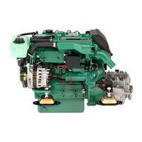
На этой странице вы можете скачать руководства пользователя (их еще называют инструкция оператора) для двигателей Volvo Penta.
Важно! Если нужное руководство не нашлось, напишите на manual@unisail.ru и мы пришлем его вам бесплатно в электронном виде. В письме укажите:
— серийный номер двигателя (предпочтительно)
или
— модель и год выпуска.
Мы постараемся прислать инструкцию в течение одного рабочего дня.
Мы не высылаем инструкции по ремонту двигателей.
Обратите внимание! Инструкции на русском языке существуют не для всех моделей двигателей Вольво Пента. В случае, если инструкция на русском недоступна, мы отправим вам ее на английском языке (если вам больше подойдет другой язык, то на нем тоже поищем).
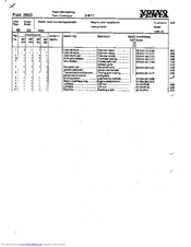
| Модель двигателя / название публикации | Дата публикации | Язык | |
| Сервисная книжка Volvo Penta | 2014 | русский* | скачать |
|
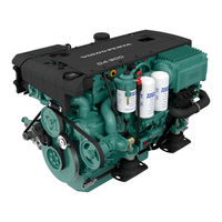
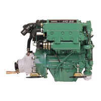
Volvo Penta D1, D2 |
2014-06 | русский | скачать |
| Volvo Penta D1, D2 | 2009-06 | русский | скачать |
| Volvo Penta D1, D2 | 2007-12 | русский | скачать |
| Volvo Penta D1, D2 | 2007-07 | русский | скачать |
| Volvo Penta D2 | 2014-06 | русский | скачать |
| Volvo Penta D2 (версия 1) | 2009-06 | русский | скачать |
| Volvo Penta D2 (версия 2) | 2009-06 | русский | скачать |
| Volvo Penta D3 (доп. для SOLAS) | 2014-11 | русский* | скачать |
| Volvo Penta D3 | 2014-06 | русский | скачать |
| Volvo Penta D3 | 2012-02 | русский | скачать |
| Volvo Penta D3 | 2010-07 | русский | скачать |
| Volvo Penta D3 | 2010-01 | русский | скачать |
| Volvo Penta D3 | 2009-05 | русский | скачать |
| Volvo Penta D3 (доп. для SOLAS) | 2007-04 | русский* | скачать |
| Volvo Penta D3 | 2006-10 | русский | скачать |
| Volvo Penta D3 | 2005-12 | русский | скачать |
| Volvo Penta D4, D6 (доп. для SOLAS) | 2015-03 | русский | скачать |
| Volvo Penta D4, D6 | 2014-12 | русский | скачать |
| Volvo Penta D4, D6 | 2011-05 | русский | скачать |
| Volvo Penta D4, D6 | 2009-08 | русский | скачать |
| Volvo Penta D4, D6 | 2009-06 | русский | скачать |
| Volvo Penta D4, D6 | 2007-06 | русский | скачать |
| Volvo Penta D4, D6 (доп. для SOLAS) | 2006-06 | русский | скачать |
| Volvo Penta D4, D6 | 2006-05 | русский | скачать |
| Volvo Penta D4, D6 | 2005-06 | русский | скачать |
| Напишите на manual@unisail.ru, если не нашли то, что ищете. Пришлем в электронном виде бесплатно! Условия в начале этой страницы. | |||
Все файлы в формате PDF. Для просмотра файлов в этом формате воспользуйтесь программой Adobe Reader, скачать которую можно здесь: https://get.adobe.com/ru/reader/.
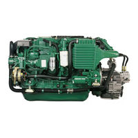
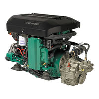
On this page you can find and free download Volvo Penta workshop, service, repair and owner’s manuals in PDF. Also here are wiring diagrams.
|
Title |
File Size |
Download Link |
|
Volvo Penta — Catalogo Motores.pdf |
7Mb |
Download |
|
Volvo Penta — Gas Engine overheat diagnosis [en].pdf |
2.5Mb |
Download |
|
Volvo Penta 2001/ 2002/ 2003/ 2003T Workshop and Repair Manual [en].pdf |
5Mb |
Download |
|
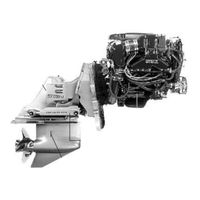
Volvo Penta 3.0L, 4.3L, 5.0L, 5.7L, 8.1LSX-A, DPS-A, XDP-B Workshop Manual [en].pdf |
29.7Mb |
Download |
|
Volvo Penta 30-GL-GS engine Workshop Manual [en].pdf |
7.5Mb |
Download |
|
Volvo Penta 4.3 a 5.0 GXI Libro De Instrucciones [es].pdf |
16.4Mb |
Download |
|
Volvo Penta 4.3GXi, 4.3OSi5.0GXi, 5.0OSi5.7Gi, 5.7GiI 5.7GXi, 5.7GXiI 5.7OSi, 5.7OSXi8.1Gi, 8.1GiI, 8.1GXi, 8.1GXiI EFI Repair manual [en].pdf |
5.2Mb |
Download |
|
Volvo Penta 5.0-5.7 GL/ Gi/ GXi/ OSXi engines Workshop Manual [en].pdf |
6.4Mb |
Download |
|
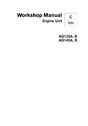
Volvo Penta AQ125A/ AQ145A engine unit Workshop Manual [en].pdf |
5.3Mb |
Download |
|
Volvo Penta D11 Operator’s Manual [En].pdf |
4Mb |
Download |
|
Volvo Penta D3 Workshop Manual [en].pdf |
4Mb |
Download |
|
Volvo Penta D4, D6, D9, D12, D16 EVC EC-C Electronic Vessel Control [en].pdf |
3.6Mb |
Download |
|
Volvo Penta D5 A T, D5A TA, D7A T, D7A TA, D7C TA libro de Instrucciones [es].pdf |
2.3Mb |
Download |
|
Volvo Penta D6 Group 30 Electrical system Workshop and Repair Manual [en].pdf |
1.2Mb |
Download |
|
Volvo Penta Efi Diagnostic Workshop Manual [en].pdf |
19.1Mb |
Download |
|
Volvo Penta EGC Diagnostics Workshop Manual [en].pdf |
4Mb |
Download |
|
Volvo Penta enginr Installation Manual.pdf |
3Mb |
Download |
|
Volvo Penta Ersatzteilkatalog.pdf |
3.7Mb |
Download |
|
Volvo Penta IPS Operator’s Manual [En].rar |
9.8Mb |
Download |
|
Volvo Penta Marine Engine Owners Manual.pdf |
785.5kb |
Download |
|
Volvo Penta Marine Engines — Wiring Diagrams [en].pdf |
1.7Mb |
Download |
|
Volvo Penta MD11C D, MD17C D engine unit Workshop Manual [en].pdf |
3.1Mb |
Download |
|
Volvo Penta MD2010, MD2020, MD2030, MD2040 Operator’s Manual [en].pdf |
6.6Mb |
Download |
|
Volvo Penta Md5a for Dummies Se Workshop Manual [en].pdf |
4.3Mb |
Download |
|
Volvo Penta MD5A Instruction book [En].pdf |
813.3kb |
Download |
|
Volvo Penta MD6A/ MD7A Workshop Manual [en].pdf |
1.6Mb |
Download |
|
Volvo Penta Mefi Product Training 2005 Student Reference Book [en].pdf |
14.9Mb |
Download |
|
Volvo Penta Sterndrive Transom Shield — Workshop Manual [en].pdf |
6.1Mb |
Download |
|
Volvo Penta TAD 1640 & 1641 & 1642 GE TAD 1641 & 1642 VE Workshop and Repair Manual [en].pdf |
3.3Mb |
Download |
|
Volvo Penta TAD1240GE, TAD1241GE/ VETAD1242GE/ VE, TWD1240VE Workshop and Repair Manual [en].pdf |
512.3kb |
Download |
|
Volvo Penta TAD650VE, TAD660VE, TAD734GE, TAD750VE, TAD760VE Workshop Manual [en].pdf |
2.3Mb |
Download |
|
Volvo Penta TAD734GE Workshop Manual [en].pdf |
36.2Mb |
Download |
Volvo Penta is a Swedish company, part of the Volvo Group, a manufacturer of marine and industrial engines.

Penta was founded in Skövde (Sweden) in 1907 to develop the first B1 marine engine. There are two versions of the appearance of the name Penta. According to one version, five people took part in
the development of the first engine. On the other — only the fifth set of drawings was approved for the creation of a motor in the gland. Penta’s engines quickly became popular. In 1927, Penta
received an order for the supply of engines for the production of the first Volvo car.
In 1935, Volvo bought the shares of Penta and since then the Volvo Penta is part of the Volvo Group.
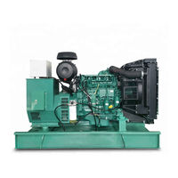
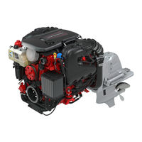
Volvo Penta supplies engines and power plants for pleasure boats and yachts, as well as boats intended for commercial use («working» boats) and diesel power plants for marine and
industrial use. The engine range consists of diesel and gasoline components, ranging from 10 to 1,000 hp.
Volvo Penta has a network of 4,000 dealers in various parts of the world.
Among the company’s innovations in the field of shipbuilding are a tilt-turn column and Duoprop counter-rotating screws. In recent years, Volvo Penta has proposed a new
propulsion system with pulling screws and a joystick to control it.
- Manuals
- Brands
- Volvo Penta Manuals
- Engine
ManualsLib has more than 684 Volvo Penta Engine manuals
Click on an alphabet below to see the full list of models starting with that letter:
1
2
3
4
5
7
8
A
B
D
H
I
K
M
P
S
T
V
Popular manuals
128 pages
D4 Operator’s Manual

136 pages
3.0GLP-C Owner’s Manual

96 pages
31 Series Workshop Manual
108 pages
D2-55 Workshop Manual
88 pages
3.0GS/SX Owner’s Manual
132 pages
MD22 Workshop Manual
104 pages
KAD/KAMD44P Operator’s Manual
74 pages
AQ145A Workshop Manual
238 pages
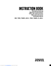
MD Instruction Manual

140 pages
IPS User Manual
133 pages
D3 Operator’s Manual
65 pages
PENTA — MANUAL SERVICE Manual
41 pages
MD7A Instruction Book
124 pages
IPS Operator’s Manual
89 pages
MS2 Workshop Manual
137 pages
D1-13 Workshop Manual

138 pages
D4 Series Operator’s Manual

64 pages
MD2010 Operator’s Manual
122 pages
TD520GE Workshop Manual
122 pages
V6 Series Operator’s Manual
Models
Document Type
1
120S

Workshop Manual
120S-B
Workshop Manual
120S-C
Workshop Manual
120S-D
Workshop Manual
120S-E
Workshop Manual
13L
Operator’s Manual
2
2001
Owner’s Manual • Workshop Manual
2002
Owner’s Manual • Workshop Manual
2003
Owner’s Manual • Workshop Manual
2003T
Owner’s Manual • Workshop Manual
21182210
Operator’s Manual
21182212
Operator’s Manual
21182213
Operator’s Manual
21182215
Operator’s Manual
21189867
Operator’s Manual
21301406
Operator’s Manual
21301407
Operator’s Manual
21301408
Operator’s Manual
230
Workshop Manual • Workshop Manual
250
Workshop Manual • Workshop Manual
251DOHC
Workshop Manual • Workshop Manual
3
3.0 GS
Operator’s Manual
3.0GL-B
Operator’s Manual
3.0GL-C
Operator’s Manual
3.0GLP-C
Owner’s Manual
3.0GLP-J
Operator’s Manual
3.0GS/SX
Owner’s Manual
3.0GXi-J
Operator’s Manual
3.0GXiC-J
Operator’s Manual
300 Series
Workshop Manual
31 Series
Workshop Manual • Instruction Book
32 Series
Workshop Manual • Instruction Book
3869351
Operator’s Manual
3869352
Operator’s Manual
3869353
Operator’s Manual
3869354
Operator’s Manual
3869355
Operator’s Manual
3869356
Operator’s Manual
3869388
Operator’s Manual
3869389
Operator’s Manual
3869390
Operator’s Manual
3869391
Operator’s Manual
3869393
Operator’s Manual
3869397
Operator’s Manual
3869399
Operator’s Manual
3869400
Operator’s Manual
3869403
Operator’s Manual
3869404
Operator’s Manual
3869407
Operator’s Manual
3869408
Operator’s Manual
3869411
Operator’s Manual
3869412
Operator’s Manual
3869415
Operator’s Manual
3869416
Operator’s Manual
3869431
Operator’s Manual
3869433
Operator’s Manual
3869435
Operator’s Manual
3869437
Operator’s Manual
3869439
Operator’s Manual
3869446
Operator’s Manual
3869447
Operator’s Manual
3869448
Operator’s Manual
3869449
Operator’s Manual
3869450
Operator’s Manual
3869459
Operator’s Manual
3869461
Operator’s Manual
4
4.3 Gi
Operator’s Manual
4.3 Gi/PJX
Owner’s Manual
4.3 GL
Operator’s Manual
4.3Gi/DP-S
Owner’s Manual
4.3Gi/SX
Owner’s Manual
4.3GL-A
Operator’s Manual
4.3GL-D
Owner’s Manual
4.3GL-J
Operator’s Manual
4.3GL/DP-S
Owner’s Manual
4.3GL/SX
Owner’s Manual
4.3GS/DP-S
Owner’s Manual
4.3GS/SX
Owner’s Manual
4.3GXI-A
Operator’s Manual
4.3GXI-B
Operator’s Manual
4.3GXI-BF
Operator’s Manual
4.3GXi-E
Owner’s Manual
4.3GXi-EF
Owner’s Manual
4.3GXi-J
Operator’s Manual
4.3OSi-B
Operator’s Manual
4.3OSi-BF
Operator’s Manual
4.3OSi-C
Operator’s Manual
4.3OSi-CF
Operator’s Manual
41 Series
Workshop Manual • Instruction Book
42 Series
Workshop Manual • Instruction Book
43 Series
Workshop Manual • Instruction Book
44 Series
Workshop Manual
5
5.0 Gi
Operator’s Manual
5.0 GL
Operator’s Manual • Manual
5.0 GXi
Manual
5.0 GXiE-J
Operator’s Manual
5.0 GXiE-JF
Operator’s Manual
5.0 OSi
Manual
5.0Gi/DP-S
Owner’s Manual
5.0Gi/SX
Owner’s Manual
5.0GL-A/B
Operator’s Manual
5.0GL-E
Owner’s Manual
5.0GL-J
Operator’s Manual
5.0GL/DP-S
Owner’s Manual
5.0GL/SX
Owner’s Manual
5.0GXI-A
Operator’s Manual
5.0GXI-B
Operator’s Manual
5.0GXI-BF
Operator’s Manual
5.0GXi-E
Owner’s Manual
5.0GXi-EF
Owner’s Manual
5.0GXi-J
Operator’s Manual
5.0GXi-JF
Operator’s Manual
5.0GXiC-J
Operator’s Manual
5.0GXiCE-M
Operator’s Manual
5.0GXiCE-MF
Operator’s Manual
5.0OSi-B
Operator’s Manual
5.0OSi-BF
Operator’s Manual
5.0OSi-C
Operator’s Manual
5.0Si-CF
Operator’s Manual
5.7 Gi
Manual
5.7 GiE-300-J
Operator’s Manual
5.7 GiE-300-JF
Operator’s Manual
5.7 GS
Operator’s Manual
5.7 GXi
Manual
5.7 GXiE-J
Operator’s Manual
5.7 GXiE-JF
Operator’s Manual
5.7 OSi
Manual
5.7 OSXi
Manual
5.7GI-A
Operator’s Manual
5.7GI-B
Operator’s Manual
5.7GI-BF
Operator’s Manual
5.7Gi-E
Owner’s Manual
5.7Gi-EF
Owner’s Manual
5.7Gi300-J
Operator’s Manual
5.7Gi300-JF
Operator’s Manual
5.7GiC-300-J
Operator’s Manual
5.7GiC-300-JF
Operator’s Manual
5.7GiCE-300-M
Operator’s Manual
5.7GiCE-300-MF
Operator’s Manual
5.7GL-A/B
Operator’s Manual
5.7GS/DP-S
Owner’s Manual
5.7GS/SX
Owner’s Manual
5.7GSi
Operator’s Manual
5.7GSi/DP-S
Owner’s Manual
5.7GXI-B
Operator’s Manual
5.7GXI-C
Operator’s Manual
5.7GXI-CF
Operator’s Manual
5.7GXi-F
Owner’s Manual
5.7GXi-FF
Owner’s Manual
5.7GXi-J
Operator’s Manual
5.7GXi-JF
Operator’s Manual
5.7GXiC-J
Operator’s Manual
5.7GXiC-JF
Operator’s Manual
5.7GXiCE-M
Operator’s Manual
5.7GXiCE-MF
Operator’s Manual
5.7OSi-A
Operator’s Manual
5.7OSi-AF
Operator’s Manual
5.7OSi-B
Operator’s Manual
5.7OSi-BF
Operator’s Manual
5.7OSXi-A
Operator’s Manual
5.7OSXi-AF
Operator’s Manual
5.7OSXi-B
Operator’s Manual
5.7OSXi-BF
Operator’s Manual
7
7.4 Gi
Owner’s Manual • Operator’s Manual
7.4 GL
Owner’s Manual
7.4 GSi
Operator’s Manual
8
8.1 GiE-J
Operator’s Manual
8.1 GiE-JF
Operator’s Manual
8.1 GXiE-J
Operator’s Manual
8.1 GXiE-JF
Operator’s Manual
8.1GI-B
Operator’s Manual
8.1Gi-F
Owner’s Manual
8.1Gi-FF
Owner’s Manual
8.1Gi-J
Operator’s Manual
8.1Gi-JF
Operator’s Manual
8.1GiC-J
Operator’s Manual
8.1GiC-JF
Operator’s Manual
8.1GiCE-M
Operator’s Manual
8.1GiCE-MF
Operator’s Manual
8.1GXI-A
Operator’s Manual
8.1GXi-E
Owner’s Manual
8.1GXi-EF
Owner’s Manual
8.1GXi-J
Operator’s Manual
8.1GXi-JF
Operator’s Manual
8.2 GL
Owner’s Manual
8.2 GSi
Operator’s Manual
A
AD31
Owner’s Manual • Instruction Manual • Owner’s Manual
AD31B
Workshop Manual
AD31D
Workshop Manual
AD31L
Workshop Manual • Instruction Book
AD31L-A
Workshop Manual
AD31P
Workshop Manual • Instruction Book
AD31P-A
Workshop Manual
AD41
Owner’s Manual • Instruction Manual • Owner’s Manual
AD41B
Workshop Manual
AD41D
Workshop Manual
AD41L
Instruction Book
AD41L-A
Workshop Manual
AD41P
Workshop Manual • Instruction Book
AD41P-A
Workshop Manual
AQ100
Operator’s Manual
AQ105A
Workshop Manual
AQ110
Operator’s Manual
AQ115A
Workshop Manual
AQ120
Operator’s Manual
AQ125A
Workshop Manual
AQ125B
Workshop Manual
AQ130A
Workshop Manual
AQ130B
Workshop Manual
AQ130C
Workshop Manual
AQ131
Workshop Manual • Workshop Manual
AQ145A
Workshop Manual
AQ145B
Workshop Manual
AQ151
Workshop Manual • Workshop Manual
AQ165A
Workshop Manual
AQ170A
Workshop Manual
AQ170B
Workshop Manual
AQ170C
Workshop Manual
AQ171
Workshop Manual • Workshop Manual
AQ205
Operator’s Manual
AQ211
Operator’s Manual
AQ231
Operator’s Manual
AQ271
Operator’s Manual
AQ311
Operator’s Manual
AQAD30/DP
Instruction Book
AQAD40/290
Instruction Book
AQAD40/DP
Instruction Book
AQD70C
Instruction Book
AQD70D
Instruction Book
AQUAMATIC 110-100
Operator’s Manual • Operator’s Manual
AQUAMATIC 120-100
Operator’s Manual • Operator’s Manual
AQUAMATIC 95-100
Operator’s Manual • Operator’s Manual
B
BB231
Operator’s Manual
BB261
Operator’s Manual
D
D
Instruction Manual
D1 Series
Operator’s Manual • Operator’s Manual • Service Manual
D1-13
Operator’s Manual • Installation Instructions Manual • Operator’s Manual • Installation Manual • Workshop Manual • Operator’s Manual • Installation Instructions Manual • Workshop Manual • Installation Manual
D1-20
Operator’s Manual • Installation Instructions Manual • Operator’s Manual • Installation Manual • Workshop Manual • Operator’s Manual • Installation Instructions Manual • Workshop Manual • Installation Manual
D1-30
Operator’s Manual • Installation Instructions Manual • Operator’s Manual • Installation Manual • Workshop Manual • Operator’s Manual • Installation Instructions Manual • Workshop Manual • Installation Manual
D11
Operator’s Manual
D11/IPS20
Operator’s Manual
D12
Operator’s Manual
D12-615
Operator’s Manual
D12-650
Operator’s Manual
D12-675
Operator’s Manual
D12-715
Operator’s Manual
D12-AUX
Operator’s Manual
D13 MH RC
Operator’s Manual
D13 MP
Operator’s Manual
D13 Series
Operator’s Manual • Operator’s Manual • Operator’s Manual
D13-300
Operator’s Manual
D13-400
Operator’s Manual
D13-450
Operator’s Manual
D13-500
Operator’s Manual
D13-550
Operator’s Manual
D13-600
Operator’s Manual
D13-700
Operator’s Manual
D13-800
Operator’s Manual
D13-900
Operator’s Manual
D13B MH
Operator’s Manual
D16
Operator’s Manual • Operator’s Manual
D16 MH
User Manual • Operator’s Manual
D2 Series
Operator’s Manual • Operator’s Manual • Operator’s Manual • Service Manual
D2-40
Operator’s Manual • Installation Instructions Manual • Operator’s Manual • Installation Manual • Workshop Manual • Operator’s Manual • Installation Instructions Manual • Workshop Manual • Installation Manual
D2-55
Operator’s Manual • Operator’s Manual • Workshop Manual • Installation Manual • Installation Instructions Manual • Installation Manual
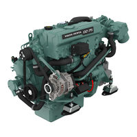
D2-75
Operator’s Manual • Operator’s Manual • Workshop Manual • Installation Manual • Installation Instructions Manual • Installation Manual
D25A MS
Operator’s Manual
D25A MT
Operator’s Manual
D3
Operator’s Manual • Operator’s Manual • Operator’s Manual
D3 290/DP
Installation Instructions Manual
D3-110i
Operator’s Manual • Operator’s Manual
D3-110i-A
Operator’s Manual
D3-130A
Operator’s Manual • Operator’s Manual
D3-130A-A
Operator’s Manual
D3-130i
Operator’s Manual • Operator’s Manual
D3-130i-A
Operator’s Manual
D3-160A
Operator’s Manual • Operator’s Manual
D3-160A-A
Operator’s Manual
D3-160i
Operator’s Manual • Operator’s Manual
D3-160i-A
Operator’s Manual
D3-190A
Operator’s Manual • Operator’s Manual
D3-190i
Operator’s Manual • Operator’s Manual
D3-SOLAS
Supplement To Operators Manual
D30A MS
Operator’s Manual
D30A MT
Operator’s Manual
D34A MS
Operator’s Manual
D34A MT
Operator’s Manual
D4
Operator’s Manual • Operator’s Manual • Operator’s Manual • Operator’s Manual • Operator’s Manual • Operator’s Manual • Operator’s Manual • Service And Maintenance Manual
D4-150A
Operator’s Manual
D4-175I
Operator’s Manual
D4-180I
Operator’s Manual
D4-225A
Operator’s Manual
D4-225I
Operator’s Manual
D4-230A
Operator’s Manual
D4-230I
Operator’s Manual
D4-260
Operator’s Manual
D4-260A
Operator’s Manual
D4-260I
Operator’s Manual
D4-270A
Operator’s Manual
D4-270I
Operator’s Manual
D4-300
Operator’s Manual
D4-300A
Operator’s Manual • Operator’s Manual
D4-300I
Operator’s Manual • Operator’s Manual
D4-320A
Operator’s Manual
D4-320I
Operator’s Manual
D4-SOLAS
Operator’s Manual
D41B
Workshop Manual
D41D
Workshop Manual
D41L
Instruction Book
D41L-A
Workshop Manual
D5
Operator’s Manual
D6
Operator’s Manual • Operator’s Manual • Operator’s Manual • Operator’s Manual • Operator’s Manual • Operator’s Manual • Operator’s Manual • Service And Maintenance Manual
D6-280A
Operator’s Manual
D6-280I
Operator’s Manual
D6-300A
Operator’s Manual
D6-300I
Operator’s Manual
D6-310
Operator’s Manual
D6-310A
Operator’s Manual
D6-310I
Operator’s Manual
D6-330
Operator’s Manual
D6-330A
Operator’s Manual
D6-330I
Operator’s Manual
D6-340A
Operator’s Manual
D6-340I
Operator’s Manual
D6-370
Operator’s Manual
D6-370A
Operator’s Manual
D6-370I
Operator’s Manual
D6-380A
Operator’s Manual
D6-380I
Operator’s Manual
D6-400A
Operator’s Manual • Operator’s Manual
D6-435
Operator’s Manual
D6-435I
Operator’s Manual
D6-440A
Operator’s Manual
D6-440I
Operator’s Manual
D6-440I-WJ
Operator’s Manual
D6-480A
Operator’s Manual
D6-480I
Operator’s Manual
D6-480I-WJ
Operator’s Manual
D6-SOLAS
Operator’s Manual
D65A MS
Workshop Manual
D65A MT
Workshop Manual
D7
Operator’s Manual
D8 2020
Operator’s Manual
D9 MH
User Manual • Operator’s Manual
D9-425
Operator’s Manual
D9-500
Operator’s Manual
D9-575
Operator’s Manual
DPS-A
Workshop Manual • Operator’s Manual • Operator’s Manual
DPX 385
Operator’s Manual
DPX 415
Operator’s Manual
DPX 500
Instruction Book
DPX 600
Instruction Book
DPX375
Operator’s Manual
DPX420
Operator’s Manual
H
HU series
Workshop Manual
I
IPS
Operator’s Manual • User Manual • Installation And System Connections
IPS 3
Installation Reference Manual
IPS 350
Operator’s Manual • Operator’s Manual • Operator’s Manual • Installations
IPS 400
Operator’s Manual • Operator’s Manual • Operator’s Manual • Installations
IPS 450
Operator’s Manual • Operator’s Manual • Operator’s Manual • Installations
IPS 500
Operator’s Manual • Operator’s Manual • Operator’s Manual • Installations
IPS 600
Operator’s Manual • Operator’s Manual • Operator’s Manual • Installations
IPS20
Installation Instructions Manual • Installation Instructions Manual
IPS30
Installation Instructions Manual • Installation Instructions Manual
IPS800
Operator’s Manual
IPS900
Operator’s Manual
K
KAD/KAMD300
Operator’s Manual
KAD/KAMD44P
Operator’s Manual
KAD300-A
Workshop Manual
KAD32P
Workshop Manual • Workshop Manual
KAD42
Owner’s Manual • Owner’s Manual
KAD42/DPX
Owner’s Manual
KAD42A
Workshop Manual • Workshop Manual
KAD42B
Workshop Manual • Workshop Manual
KAD42L
Instruction Book
KAD42P
Workshop Manual • Workshop Manual • Instruction Book
KAD43P
Workshop Manual • Workshop Manual
KAD44P
Workshop Manual
KAD44P-A
Workshop Manual
KAD44P-B
Workshop Manual
KAD44P-C
Workshop Manual
KAMD300
Installation Manual
KAMD300-A
Workshop Manual
KAMD42
Owner’s Manual • Owner’s Manual
KAMD42A
Workshop Manual • Workshop Manual
KAMD42B
Workshop Manual • Workshop Manual
KAMD42L
Instruction Book
KAMD42P
Workshop Manual • Workshop Manual • Instruction Book
KAMD43
Installation Manual
KAMD43P
Workshop Manual • Workshop Manual
KAMD44
Installation Manual
KAMD44P
Workshop Manual
KAMD44P-A
Workshop Manual
KAMD44P-B
Workshop Manual
KAMD44P-C
Workshop Manual
M
M2.04
Installation Instructions Manual
M2.06
Installation Instructions Manual
M2.C5
Installation Instructions Manual
M2.D5
Installation Instructions Manual
M3.09
Installation Instructions Manual
M3.10
Installation Instructions Manual
M4.14
Installation Instructions Manual
M4.15
Installation Instructions Manual
M4.17
Installation Instructions Manual
MB 10 A
Instruction Book
MD
Instruction Manual
MD 11C/110S
Instruction Book
MD 17C/110S
Instruction Book
MD1B
Workshop Manual • Instruction Book
MD2010
Operator’s Manual • Instruction Book • Instruction Book
MD2020
Operator’s Manual • Instruction Book • Instruction Book
MD2030
Operator’s Manual • Instruction Book • Instruction Book
MD2040
Operator’s Manual • Instruction Book • Instruction Book
MD21A
Operator’s Manual
MD22
Instruction Book • Workshop Manual
MD22L
Instruction Book
MD29A
Operator’s Manual
MD2B
Workshop Manual • Instruction Book
MD30/MS2
Instruction Book
MD30/MS2V
Instruction Book
MD31A
Workshop Manual
MD3B
Workshop Manual • Instruction Book
MD6A
Workshop Manual
MD7A
Workshop Manual • Instruction Book
MD7A/110S
Instruction Book
MS10
Installation Instructions Manual
MS15
Installation Instructions Manual
MS2
Workshop Manual
MS2A-D
Workshop Manual
MS2A-E
Workshop Manual
MS2B-A
Workshop Manual
MS2B-L
Workshop Manual
MS2L-D
Workshop Manual
MS2L-E
Workshop Manual
MS2V
Workshop Manual
P
P4.4.19
Installation Instructions Manual
PENTA
Operator’s Manual • Manual • Owner’s Manual • Launch Manual
S
SX-A
Workshop Manual • Operator’s Manual • Operator’s Manual
T
TAD1170
Operator’s Manual
TAD1170VE
Operator’s Manual
TAD1171VE
Operator’s Manual
TAD1172VE
Operator’s Manual • Operator’s Manual
TAD1240GE
Operator’s Manual • Technical Description
TAD1241GE
Operator’s Manual • Technical Description
TAD1241VE
Operator’s Manual • Technical Description
TAD1242GE
Technical Description • Operator’s Manual • Technical Description
TAD1242VE
Operator’s Manual • Technical Description
TAD1340VE
Operator’s Manual
TAD1341GE
Operator’s Manual
TAD1341VE
Operator’s Manual
TAD1342GE
Operator’s Manual
TAD1342VE
Operator’s Manual
TAD1343GE
Operator’s Manual
TAD1343VE
Operator’s Manual
TAD1344GE
Operator’s Manual
TAD1344VE
Operator’s Manual
TAD1345GE
Operator’s Manual
TAD1345VE
Operator’s Manual
TAD1350GE
Operator’s Manual
TAD1350VE
Operator’s Manual
TAD1351GE
Operator’s Manual
TAD1351VE
Operator’s Manual
TAD1352GE
Operator’s Manual
TAD1352VE
Operator’s Manual
TAD1353GE
Operator’s Manual
TAD1353VE
Operator’s Manual
TAD1354GE
Operator’s Manual
TAD1355GE
Operator’s Manual
TAD1381VE
Operator’s Manual
TAD1382VE
Operator’s Manual
TAD1383VE
Operator’s Manual
TAD1384VE
Operator’s Manual
TAD1385VE
Operator’s Manual
TAD1630G
Workshop Manual
TAD1630GE
Workshop Manual
TAD1630P
Workshop Manual
TAD1630V
Workshop Manual
TAD1631G
Workshop Manual
TAD1631GE
Workshop Manual
TAD1640GE
Operator’s Manual
TAD1640GE-B
Operator’s Manual
TAD1640VE-B
Operator’s Manual
TAD1641GE
Operator’s Manual
TAD1641GE-B
Operator’s Manual
TAD1641VE
Operator’s Manual
TAD1641VE-B
Operator’s Manual
TAD1642GE
Operator’s Manual
TAD1642GE-B
Operator’s Manual
TAD1642VE
Operator’s Manual
TAD1642VE-B
Operator’s Manual
TAD1643VE
Operator’s Manual • Operator’s Manual
TAD1643VE-B
Operator’s Manual
TAD1650GE
Operator’s Manual • Operator’s Manual
TAD1650VE
Operator’s Manual • Operator’s Manual
TAD1650VE-B
Operator’s Manual
TAD1651GE
Operator’s Manual • Operator’s Manual
TAD1651VE
Operator’s Manual
TAD1660VE
Operator’s Manual
TAD1661VE
Operator’s Manual
TAD1662VE
Operator’s Manual
TAD1670VE
Operator’s Manual
TAD1671VE
Operator’s Manual
TAD1672VE
Operator’s Manual
TAD420VE
Workshop Manual
TAD520GE
Workshop Manual • Workshop Manual
TAD520VE
Workshop Manual • Workshop Manual
TAD530
Workshop Manual
TAD530GE
Workshop Manual
TAD531
Workshop Manual
TAD531GE
Workshop Manual
TAD532GE
Workshop Manual • Workshop Manual
TAD550GE
Operator’s Manual
TAD551GE
Operator’s Manual
TAD560VE
Operator’s Manual
TAD561VE
Operator’s Manual
TAD570VE
Operator’s Manual • Operator’s Manual
TAD571VE
Operator’s Manual • Operator’s Manual
TAD572VE
Operator’s Manual • Operator’s Manual
TAD620VE
Workshop Manual
TAD650VE
Workshop Manual
TAD660VE
Workshop Manual
TAD720GE
Workshop Manual • Workshop Manual
TAD720VE
Workshop Manual • Workshop Manual
TAD721GE
Workshop Manual • Workshop Manual
TAD721VE
Workshop Manual • Workshop Manual
TAD722GE
Workshop Manual • Workshop Manual
TAD722VE
Workshop Manual • Workshop Manual
TAD730
Workshop Manual
TAD730GE
Workshop Manual
TAD731
Workshop Manual
TAD731GE
Workshop Manual
TAD732
Workshop Manual
TAD732GE
Workshop Manual
TAD733GE
Workshop Manual • Workshop Manual
TAD734GE
Manual • Installation Manual
TAD750GE
Operator’s Manual
TAD750VE
Workshop Manual
TAD751GE
Operator’s Manual
TAD752GE
Operator’s Manual
TAD753GE
Operator’s Manual
TAD754GE
Operator’s Manual
TAD760VE
Workshop Manual
TAD761VE
Operator’s Manual
TAD762VE
Operator’s Manual
TAD763VE
Operator’s Manual
TAD764VE
Operator’s Manual
TAD765VE
Operator’s Manual
TAD870VE
Operator’s Manual • Operator’s Manual
TAD871VE
Operator’s Manual • Operator’s Manual
TAD872VE
Operator’s Manual • Operator’s Manual
TAD873VE
Operator’s Manual • Operator’s Manual
TAD940GE
Workshop Manual
TAD940VE
Workshop Manual
TAD941GE
Workshop Manual
TAD941VE
Workshop Manual
TAD942VE
Workshop Manual
TAD943VE
Workshop Manual
TAD950VE
Workshop Manual
TAD951VE
Workshop Manual
TAD952VE
Workshop Manual
TAMD
Instruction Manual
TAMD103A
Operator’s Manual
TAMD162C
Instruction Book
TAMD163A
Instruction Book
TAMD163P
Instruction Book
TAMD22
Workshop Manual
TAMD30/MS3C
Instruction Book
TAMD31
Owner’s Manual • Workshop Manual • Installation Manual
TAMD31B
Workshop Manual
TAMD31D
Owner’s Manual • Workshop Manual
TAMD31L
Workshop Manual • Instruction Book
TAMD31L-A
Workshop Manual
TAMD31M
Workshop Manual • Instruction Book
TAMD31M-A
Workshop Manual
TAMD31P
Workshop Manual • Instruction Book
TAMD31P-A
Workshop Manual
TAMD31S-A
Workshop Manual
TAMD40/MS3C
Instruction Book
TAMD41
Owner’s Manual • Workshop Manual • Installation Manual
TAMD41B
Workshop Manual
TAMD41D
Owner’s Manual • Workshop Manual
TAMD41H
Workshop Manual • Instruction Book
TAMD41H-A
Workshop Manual
TAMD41H-B
Workshop Manual
TAMD41L-A
Workshop Manual
TAMD41M
Workshop Manual • Instruction Book
TAMD41M-A
Workshop Manual
TAMD41P
Workshop Manual • Instruction Book
TAMD41P-A
Workshop Manual
TAMD42
Installation Manual
TAMD42A
Instruction Book
TAMD42AWJ
Workshop Manual
TAMD42BWJ
Workshop Manual
TAMD42WJ
Workshop Manual • Workshop Manual • Instruction Book
TAMD60A
Instruction Book
TAMD60B
Instruction Book
TAMD61A
Workshop Manual
TAMD62A
Workshop Manual
TAMD63L
Operator’s Manual • Instruction Book • Instruction Book
TAMD63L-A
Workshop Manual
TAMD63P
Operator’s Manual • Instruction Book • Instruction Book
TAMD63P-A
Workshop Manual
TAMD70C
Instruction Book
TAMD70D
Instruction Book
TAMD71A
Workshop Manual
TAMD71B
Workshop Manual • Instruction Book • Instruction Book • Instruction Manual
TAMD72A
Workshop Manual
TAMD72P
Instruction Book
TAMD72P-A
Workshop Manual
TAMD72WJ
Instruction Book
TAMD72WJ-A
Workshop Manual
TAMD73P
Instruction Book
TAMD73WJ
Instruction Book
TAMD74A
Operator’s Manual • Operator’s Manual
TAMD74C
Instruction Book
TAMD74L
Instruction Book
TAMD74P
Instruction Book
TD164KAE
Workshop Manual
TD420VE
Workshop Manual
TD520GE
Workshop Manual • Workshop Manual
TD520VE
Workshop Manual • Workshop Manual
TD720GE
Workshop Manual • Workshop Manual
TD720VE
Workshop Manual • Workshop Manual
TDM22
Instruction Book
TID162AP
Workshop Manual
TMD
Instruction Manual
TMD22
Instruction Book • Workshop Manual
TMD30/MS3C
Instruction Book
TMD31
Owner’s Manual • Owner’s Manual
TMD31B
Workshop Manual
TMD31D
Workshop Manual
TMD31L
Instruction Book
TMD31L-A
Workshop Manual
TMD40/MS3C
Instruction Book
TMD41
Owner’s Manual • Owner’s Manual
TMD41B
Workshop Manual
TMD41D
Workshop Manual
TMD41L
Instruction Book
TMD41L-A
Workshop Manual
TWD1240VE
Operator’s Manual • Technical Description
TWD1620G
Workshop Manual
TWD1620GH
Workshop Manual
TWD1630G
Workshop Manual
TWD1630GE
Workshop Manual
TWD1630P
Workshop Manual
TWD1630V
Workshop Manual
TWD1643GE
Operator’s Manual • Operator’s Manual
TWD1644GE
Operator’s Manual
TWD1645GE
Operator’s Manual
TWD1652GE
Operator’s Manual
TWD1653GE
Operator’s Manual
TWD1672GE
Manual
TWD1673GE
Manual
V
V6 Series
Operator’s Manual
V6-200
Operator’s Manual
V6-200-C Series
Operator’s Manual
V6-225
Operator’s Manual
V6-240
Operator’s Manual • Operator’s Manual
V6-240-C Series
Operator’s Manual
V6-250
Operator’s Manual
V6-250-C Series
Operator’s Manual
V6-280
Operator’s Manual • Operator’s Manual • Operator’s Manual
V6-280-C Series
Operator’s Manual
V8 Series
Operator’s Manual
V8-225
Operator’s Manual
V8-225-C
Operator’s Manual
V8-225-CE
Operator’s Manual
V8-270
Operator’s Manual
V8-270-C
Operator’s Manual
V8-270-CE
Operator’s Manual
V8-300
Operator’s Manual • Operator’s Manual • Operator’s Manual • Operator’s Manual
V8-300-C Series
Operator’s Manual • Operator’s Manual
V8-300-CE
Operator’s Manual
V8-320
Operator’s Manual
V8-320-C
Operator’s Manual
V8-320-CE
Operator’s Manual
V8-350
Operator’s Manual • Operator’s Manual • Operator’s Manual • Operator’s Manual
V8-350-C Series
Operator’s Manual • Operator’s Manual
V8-380
Operator’s Manual • Operator’s Manual • Operator’s Manual • Operator’s Manual • Operator’s Manual
V8-380-C Series
Operator’s Manual • Operator’s Manual
V8-380-CE
Operator’s Manual
V8-400
Operator’s Manual
V8-430
Operator’s Manual • Operator’s Manual
V8-430-C Series
Operator’s Manual
Page 2 — Workshop Manual
7Repair InstructionsThe work methods described in the Workshop Manualare applicable for a workshop environment. The drivehas removed from the boat and
Page 3
97Repair instructions9. Install special tool 884830 onto the splines end andturn the gear in the set direction of rotation, clockwisefor left handed p
Page 4 — Contents
98Repair instructionsFinal assembly1. Dismantle pinion and gear and clean parts frommarking dye and then assemble with the calculatedshims. Then insta
Page 5
99Repair instructionsReconditioning the lower gear,models 280-DP, 290-DP and DPDisassembly1. Clean the sterndrive externally.2. Drain the oil by remov
Page 6 — Safety Information
100Repair instructions7. Remove the two Allen-head screws from the propel-ler bearing housing. Key width: 3/8”.8. Install special tool 884789 on the o
Page 7
101Repair instructions13. Remove the nut from the pinion gear.Use a 23 mm wrench.NOTE! Do not discard the nut. Put it aside for use inthe shimming pro
Page 8
102Repair instructions17. Remove the forward gear bearing outer race fromthe lower unit, using special tool 884794 and slidehammer 884161. Remove the
Page 9
103Repair instructions21. Install a knife puller on the outer propeller shaftroller bearing. Using a press, remove the roller bear-ing.IMPORTANT! Make
Page 10 — Repair Instructions
104Repair instructions25. Remove the outer bearing race using special tools884796 and handle 9991801.IMPORTANT! Center the tool carefully. Locate apai
Page 11 — Strength classes
105Repair instructions30. Check the bearing race. Replace as necessary,using a knife puller. Clean and check all parts forwear.AssemblyShimming the fr
Page 12 — General Information
106Repair instructions3. The nominal measurement of the forward gear is39.50 mm. The tolerance (±) is engraved on the gear.All engraved numbers are de
Page 13 — Special tools
8General InformationSafety instructions forfluororubberFluororubber is a common material used in sealingrings for shafts and O-rings.Hydrofluoric acid
Page 14
107Repair instructions6. Use special tool 884263 to press the gear and bear-ing assembly onto the propeller shaft. Use special tool884799 to protect t
Page 15
108Repair instructions12. Find the “H”-marking on the parting plane of thelower gear housing. The “H”-stamping in this instanceis 37. Remember, the st
Page 16
109Repair instructions14. The nominal measurement of the vertical shaft is217.75 mm. This measurement is added to the cal-culated pinion measurement o
Page 17 — Chemicals
110Repair instructions18. Hold the pinion nut with a 23 mm socket. Use spe-cial tool 884830, or 3850598 as an alternative, and atorque wrench. Torque
Page 19
112Repair instructions27. Now add the front and rear gear shims.Add:Forward gear shims 0.60 mmAft gear shims + 0.31 mm0.91 mmAdd nominal value + 120.0
Page 21
114Repair instructions35. Grease the bearing box and install on the lowerunit. Tighten the allen bolts to 40 Nm (29 lb.ft.).36. Place the outer bearin
Page 22 — Design and function
115Repair instructionsChecking preload39. After calculating the shims required according topoints “A” and “B”, place the calculated shim on topof the
Page 23 — DP-B, DP-C
116Repair instructions43. Move the dial indicator gauge to the outer nut.Measure the backlash of the rear gear the same wayas the front gear. The clea
Page 24 — Removing the sterndrive
9General InformationSealantA number of different types of sealant and locking flu-ids are used on the engine. The sealant has differentproperties for
Page 25
117Repair instructions47. If the contact pattern is toward the root of thetooth and at the big end, the shims should be in-creased under the front and
Page 26
118Repair instructions3. Grease the new seal rings and install in the propel-ler shaft. Turn the steel edge (1) facing forward. Usespecial tool 884975
Page 27
119Repair instructions9. Install new O-rings (1) on the bearing box. Coat theentire sealing surface and O-rings with Volvo Pentapart no. 1141570-0 sea
Page 28 — Models SP and DP
120Repair instructions1. Place the bearing race on the bearing and hold inposition. Using a depth gauge, measure the bearingheight above the lower uni
Page 29
121Repair instructions5. Use new screws and washers. Coat the screwthreads with thread locking compound, Volvo Pentapart no. 1161053-2, or Loctite® 24
Page 30
122Repair instructionsShimming the upper gear to theintermediate housing1. Measure the distance from the bottom of the uppergear housing to the top of
Page 31
123Repair instructions6. Install the upper gear housing on the intermediatehousing. Use new Allen bolts (1, 2 pcs), washers (2,2 pcs) and nyloc nuts (
Page 32
124Repair instructionsBefore filling the drive with gear oil, it must be pres-sure and vacuum tested to verify proper sealing duringassembly.Pressure/
Page 33 — 280, 285 and 290
125Repair instructionsInstalling the sterndriveModels 280 and 285There are 2 types of exhaust bellows. One type withan exhaust valve and one without.
Page 34
126Repair instructions6a. Sterndrives of later manufacture:Lower the steering helmet and grease the ‘attachmentbolt’ with grease. Turn the recessed ho
Page 35
10Special toolsIn all cases where it has been practically possible tools have been punched with their tool number, excludingthe last digit. The last d
Page 36
127Repair instructions7. Check that the control lever and the shift lever ofthe sterndrive both are in a neutral position. Removethe locking nut for t
Page 37
128Repair instructionsInstalling a ‘short hub’ type ofpropeller (B)1. Grease the propeller shaft with a thin layer ofgrease.2. Install the fishing lin
Page 38
129Repair instructionsThe Duoprop, earlier modelCheck the speed range of the relevant boat and selectthe correct propeller. See Propeller recommenda-t
Page 39 — Forward and reverse gears
130Repair instructionsThe electro-mechanicalsterndrive tilting device,model 280/285Repair instructionsOperating failures of the sterndrive tilting dev
Page 40 — Method 1
131Repair instructions1c. Mechanical faultCheck to make sure that the cover does not pressagainst the limit switch by removing the cover andtesting th
Page 41 — Method 2
132Repair instructionsModels 290, SP and DP1. Install the exhaust bellows on the transom shield.Turn the hose clamp so that the tightening screwends u
Page 42
133Repair instructions5. Remove the cover over the shift mechanism.Hang a hose clamp on the sterndrive and install theyoke on the sterndrive. Then lif
Page 43
134Repair instructions9. Push the sterndrive forwards. Lift up the trim cyl-inders simultaneously and continue to push thesterndrive forwards.10. Push
Page 44
135Repair instructions13. Pull down the retaining pawl and lift up the stern-drive sufficiently to allow the installation of specialtool 885143 betwee
Page 45
136Repair instructions17. Install the cotter pins (1). Fold the ‘legs’ back-wards carefully.18. Lower the steering helmet and align the helmetbushing
Page 46
11Special tools884267-6 Tool, dismantling vertical shaft884283-3 Drift for the installation of sealing rings inpropeller bearing housing and of propel
Page 47
137Repair instructionsAdjusting the retaining pawl,model 290a) Set the control lever in the ‘Forward’ position andcheck that the lever (8) does not to
Page 48
138Repair instructionsLocking the propeller cone on sterndrives of earliermanufacture is done by a folding washer and on stern-drives of later manufac
Page 49 — 290A, SP and DP
139Repair instructionsChanging the direction of thepropeller rotation, SP drivesThe sterndrives are supplied adjusted for left hand ro-tation ‘A’. In
Page 50
140Repair instructionsAdjustment of trim finThe trim fin is factory set at 5° towards port side. Af-ter installation the adjustment of the trim fin sh
Page 51
141Repair instructionsDuoprop propellers are available in two versions asfollows:A-marked propellers shall only be used with dieselengines.B-marked pr
Page 52
142Changing trim cylinders,models 290, SP and DP1. Remove the sterndrive when the boat is on land.Also remove the exhaust bellows and the universaljoi
Page 53 — Assembly, models
143Transom shield7. Remove the locking bolt for the trim cylinder dowelpin. Key width 10 mm.Trim cylinders, all modelsPart no.9401946. Install a greas
Page 54
144Transom shield11. Always use a new O-ring (1) on the dowel pin dur-ing reassembly. Check the pin hole and pin forscratches or other damage. Positio
Page 55
145Transom shield13. Remove any shipping plugs installed in the newtrim cylinder.Install the pipes and the hoses on the new trimcylinder.WARNING! Make
Page 56
146Transom shield18. Should the low pressure hoses (1) and high pres-sure hoses (2) need to be disconnected for any rea-son it is vital that they be r
Page 57
12Special tools884794-9 Puller, forward bearing race remover, low-er884795-6 Bearing install tool, lower884796-4 Drift, bearing remover, lower884797-2
Page 58
147Transom shieldChanging steering helmetTo ensure the integrity of the steering system thesteering helmet is not serviceable as a separate partfrom t
Page 59
148Transom shield23. Install a new bushing (8) into the new steeringfork.24. Align the square/the splines on the steering forkwith the square in the t
Page 60
149Transom shield28. Install a new seal (9) and O-ring (7) on the gearwheel.Install the trim sending unit, gear wheel and gear rack.See chapter Trim S
Page 61
150Trim systemChanging the sending unit1. Lower the sterndrive to the full down position. Turnthe helm full starboard. Using a 13 mm wrench, re-move t
Page 62
151Trim system5. -4 should be shown in the instrument window for a12º transom angle. Move the sending unit in eitherdirection until the correct number
Page 63
152Trim system3. Turn the gear wheel until the tooth with a white re-cessed marking appears.4. Install the new gear rack with the marked tooth ofthe g
Page 64
153Trim system8. -4 should be shown in the instrument window for a12º transom angle. Move the sending unit in eitherdirection until the correct number
Page 65
154Trim system4. Grease the new gear wheel shaft and O-ring liberal-ly with Volvo Penta Propeller shaft grease 828250-1.Install the new gear wheel wit
Page 66
155Trim system8. After all adjustments are made, tighten the trimsender bracket hold down screw. Be sure the sendingunit does not move when the bracke
Page 67 — Shift mechanism type 1
156Trim systemRemoving the trim pump from theboatTurn off the main battery switch. Disconnect thetrim pump wiring harness, ground cable from the fly-w
Page 68
13Special tools884978 884982 885008885009 885043 885127 885143 885146885148 885153885197 885207 885208884975-41)Installation tool884976-21 )Protection
Page 69 — Shift mechanism type 2
157Trim systemReplacing adapter and pumpassemblyTo install a new filter, place a 5/8″ socket over the fil-ter and gently tap it down using a hamm
Page 70
158Trim systemThe relief valve assembliesIf the original factory fitted valves have to be re-moved, this will alter the factory setting, and newvalves
Page 71 — Shift mechanism type 3
159Trim system4. The instrument, when trimmed down and with aknown transom angle, shows the following figures,see table below:5. If the instrument sho
Page 73
161Sterndrive extensionsThe 1″ extensionCoat the contact surfaces with a sealant. Use the 3new O-rings and the oil pipe from the extension kit. I
Page 74 — Assembly, models SP and DP
162WeldingWelding on certain parts of the sterndrive and thetransom shield is allowed. Extreme caution must beused to prevent damage to the precision
Page 75
163PaintingPainting the sterndrive andunderwater hullGeneralMost countries have introduced legislation controllingthe use of anti-fouling agents. In s
Page 76 — Intermediate housing
164Electrical wiring diagramsModel 280, tilting deviceReferences:1. Relay box2. Relay3. Limit switch4. Push rod, retaining pawl5. Connector6. Electric
Page 77
165Electrical wiring diagramsModel 280, Power trim1. Pump motor2. Relay3. Fuse4. Switch5. Body6. Trim gauge7. Sender8. Relay9. Bypass switch10. Trim l
Page 78
166Electrical wiring diagramsModel 290, Power trimEarlier modelCable colour codesR= redSB = blackGN = greenBL = blueW = whiteR/W = red/whiteGN/W = gre
Page 79
14Special tools385587699918013810105-1 Pin installer, intermediate3810152-3 Drive pressure tester3850598-8 Spline socket, upper & lower3850608-5 S
Page 80 — 290 and 290A
167Electrical wiring diagramsModels 290, SP and DP, Power trimLater model1. Oil pump2. Fuse 55 amps3. Trim sender4. Trim indicator5. Switch6. Switch-r
Page 81
168Technical dataModels 280, 280T, 280PT, 285, 285A and 290General DataType designation…
Page 82
169Technical DataLubricating systemPump, type … Circulation pump for distr
Page 83
170Technical dataModels 280-DP, 280DP/PT, 290DP and 290A-DPGeneral DataType designation…
Page 84
171Technical DataLubricating systemPump, type … Circulation pump for distr
Page 85 — SP and DP
172Technical dataModels SP-A, SP-A1, SP-A2 and SP-CGeneralDataType designation… Aq
Page 86
173Technical DataTightening torques Nm Lb. ft.Upper nut on vertical shaft (upper gear)… 125 92Tightening universal j
Page 87
174Technical dataModels DP-A, DP-A1, DP-A2, DP-B, DP-B1, DP-C and DP-C1General DataType designation…
Page 88
175Technical DataTightening torques Nm Lb. ft.Upper nut on vertical shaft (upper gear)… 125 92Tightening universal j
Page 89
176References to Service BulletinsGroup No. Date Concerning…
Page 90
15AQ 280 PTPower trimRatio:1.61:11.89:1Oil:Same as engineQty: 2.6 liters (2.74 qts)AQ285AQ 285AElectro mechanical tiltPower steeringOil:Same as engine
Page 91
Report formDo you have any complaints or other comments about this manual. Pleasemake a copy of this page, write your comments down and send them to u
Page 93
16Drive models and generationsAQ 290AQ 290AOil:Same as engineQty: 2.6 liters (2.74 qts)Ratio:1.61:11.89:12.15:1New transom shieldHook up forkSP-ARatio
Page 95
17Drive models and generationsSP-A2Ratio:1.61:11.89:1Sliding sleeve (steel)CoverGear setOil:Same as engineorFully syntheticAPI GL-5 SAE 75W–90Qty: 2.
Page 96 — The propeller shaft
18Drive models and generationsDP-B1Oil:Fully syntheticAPI GL-5 SAE 75W–90Qty: 2.7 liters (2.85 qts)Ratio:1.78:11.95:12.30:1CoverBall bearingUniversal
Page 97 — Shimming
19Section through the sterndrive1. Steering arm2. Electro-mechanical tiltingdevice3. Steering yoke4. Rubber cushion5. Universal joint6. Steering helme
Page 98
20Design and functionSection through the sterndrive, showing model DP1. Transom shield2. Trim cylinder3. Hook up fork4. Steering yoke5. Steering helme
Page 99
21Removing the sterndriveModels 280, 285 and 2901. Remove the propeller of the Singleprop sterndriveaccording to the picture.2. Remove the propellers
Page 100 — Contact pattern
22Removing the sterndrive3. Remove the Allen-head bolts holding the zinc ringand remove it.4. Remove the oil drain plug and drain off the oil. Alsorem
Page 101 — Final assembly
23Removing the sterndrive7a. Sterndrive models 280 and 285: Remove thesteering helmet and the universal joint rubber bellowsfrom the upper gear housin
Page 102 — Disassembly
24Removing the sterndrive7b. Sterndrive model 290: Remove the steering hel-met and the universal joint rubber bellows from the up-per gear housing (1)
Page 103 — Repair instructions
25Removing the sterndrive6. Remove the shift linkage cover.1. Disconnect power to prevent accidental starting.2. Move control to reverse.3. Loosen pro
Page 104
26Removing the sterndrive7. Remove the cotter pin and washer from the shiftcable end. Remove the end pivot pin from the cable.8. Loosen screw holding
Page 107 — Forward gear
28Removing the sterndrive15. Install special tool 885146 and remove the stern-drive from the transom shield.885146
Page 108 — Assembly
29Repair instructionsUpper gear housing1. Place a drain pan under the sterndrive. Remove thedrain plug (1) and drain oil from drive. Reinstall thedrai
Page 109
30Repair instructionsDisassembly, models280, 285 and 2901. Remove the shift rod (1) from the shift plate (2). Re-move the screws (3) and the nuts (4)
Page 111
32Repair instructions9. Lift out the upper gear and the bearing box as wellas the engagement sleeve.10. Lift off the upper gear housing from the speci
Page 112
33Repair instructions16. Remove the locking ring (1) and the sealing (2).NOTE! Always replace the sealing!17. Press out the input gear. Use special to
Page 113 — Shimming the bearing box
34Repair instructions18. If required press off the roller bearing (1) from thegear using a knife puller. The bearings (1) and (4)can be changed separa
Page 114
35Repair instructions3. Rotate the bearings a couple of turns to allow themto ”set”. Check the prestressing with a spring scaleand a piece of string,
Page 115
36Repair instructions5. Measure the depth of the recess in the collar wash-er “E” and add to this measurement a number ofshims (5) that the measuremen
Page 116
1General Information …3Safety Information …
Page 117
37Repair instructionsShimming the forward and reversegearsMethod 19. Measurement “A” is fixed at 62.05 mm (2.443″).10. Add or subtract the plus o
Page 119 — Contact Pattern
39Repair instructions15. Brace the special tool 884387 in a vice and installthe gear housing in the tool.16. Install the preassembled double bearing b
Page 120
40Repair instructions19. When the correct backlash has been obtained,dismantle the double bearing box and the clamp ring.In order to obtain a clear pi
Page 121
41Repair instructionsFinal assembly1. Install the lower gear along with the calculatednumber of shims.2. Install the washer (1), the locking ring (2),
Page 122 — Marine Electrical Sys
42Repair instructions3. Install the needle bearings (1) and the spacer ring(2) between the bearings in the lower gear and insertthe shaft in the gear.
Page 123
43Repair instructions7. Measure the shim thickness between the clampring and the gear housing as follows:Hold the double bearing box as indicated in t
Page 124
44Repair instructions10. Install the shims and the 2 new O-rings on thedouble bearing box.11. Install the clamp ring and the double bearing boxon the
Page 125
45Repair instructions14. Coat the contact surface with Volvo Penta part no.1141570-0 sealant and install the sealing ring (1) in away that the sealing
Page 126
46Repair instructions1. Install the upper gear housing on special tool884830. This special tool, of earlier manufacture, alsocarries the part no 88426
Page 128 — Installing the sterndrive
47Repair instructions5. Remove the 4 screws holding the gear housing cov-er.6. Remove the cover.NOTE! The front right hand screw (1) is a hollowscrew
Page 129
48Repair instructions10. Remove the needle bearings (1) from the upperand lower gear cup assemblies.Model 290A only: Also remove the spacerring (2).NO
Page 131 — Oil filling
50Repair instructions1. Install the outer bearing race. Use special tool no884932.NOTE! Make sure that the double bearing box is posi-tioned horizonta
Page 132 — The Duoprop, earlier model
51Repair instructions2. Install the bigger roller bearing on the gear wheel bypressing it on. Use special tool 884263.NOTE! Protect the gear teeth. Th
Page 133
52Repair instructions6. Insert the universal joint into the double bearing boxand brace the universal joint in a vice. Install the coni-cal washer and
Page 135 — Models 290, SP and DP
54Repair instructionsShimming the forward and reversegearsMethod 110. Measurement “A” is fixed at 62.05 mm (2.443″).11. Add or subtract the plus
Page 136
55Repair instructions13. Insert a 0.2 mm (0.008″) shim (1) under both for-ward and reverse gears as a starting point. The shimvalue is a number d
Page 137
56Repair instructions18. Use sufficient number of shims to create clear-ance of max. 0.1 mm (0.004”) between the top coverand the upper gear housing a
Page 138
3Safety InformationIntroductionThe Workshop Manual contains technical data, de-scriptions, and repair instructions for the designatedVolvo Penta produ
Page 139
57Repair instructions20. Remove the double bearing box when the correctbacklash has been obtained.To gain a clearer picture of the contact pattern, co
Page 141
59Repair instructions13. Install the needle bearings (1) and the spacer ring(2, model 290A only) between the bearings in thelower gear and insert the
Page 143 — Twin engine installation
61Repair instructions11. Coat the cover with sealant, Volvo Penta part no.1141570-0 and install the sealing ring (1) so that thesealing for the front
Page 144 — Duoprop (later model)
62Repair instructions11. Remove the locking rings (1) holding the needlebearing in the yoke.NOTE! To avoid having the locking rings “jump out”and gett
Page 145 — Transom shield
63Repair instructions5. Use a small amount of water resistant EP bearinggrease, Volvo Penta part no. 1161246-2, to retain theneedle bearings in the ca
Page 146
64Repair instructionsShift mechanism type 12. Knock out the load pin (1, figure above) and pull outthe pin (2). Remove the locking wire (3), the sprin
Page 147
65Repair instructions4. Insert the excentric piston (1). Install the pin (2) andlock it with the load pin (3). Make sure that the loadpin centers in t
Page 148
66Repair instructionsShift mechanism type 28. Knock out the load pin (1, figure above) and pull outthe pin (2) and the excentric piston (3). Remove th
Page 149
4General InformationStop the engine and close the bottom valve be-fore working on the cooling system.Only start the engine in a well-ventilated area.E
Page 150 — Changing steering helmet
67Repair instructions9. Lubricate the sealing ring abundantly and install itwith the steel edge (small clearance) facing inwardsthe gear housing.10. I
Page 151
68Repair instructionsShift mechanism type 315. Remove the sliding shoe (1) and the spring (2) andthe O-ring (3).12313. Set the shift mechanism in a po
Page 152 — Trim System
69Repair instructions16. Knock in the load pin as far as necessary to freethe pin (1).117. Pull out the pin.18. Pull out the excentric piston.19. Tap
Page 153 — Trim system
70Repair instructions24. Install the shift mechanism in the gear housing ina way that the screw (1) is displaced towards star-board.NOTE! Make sure th
Page 155
72Repair instructions31. Do not attempt to mount the special tool 3856761on any raised portion or raised lettering on the shifthousing. The tool shall
Page 156
73Repair instructionsIntermediate housingReconditioning theintermediate housing, model280 and 2851. Remove the 2 screws holding the hose connection(1)
Page 157
74Repair instructions5. Press out the bushing (1). Use special tool 884259.6. Should the shift yoke need to be replaced, removethe cotter pin (1). The
Page 158 — The power trim pump
75Repair instructionsAssemblyOil all moving parts and the screws prior to as-sembly.9. Install the shaft (53) on one of the retaining pawls(42) and th
Page 159 — Removing the oil reservoir
76Repair instructions12. Press in both sealing rings. Use special tool884259.NOTE! The sealing rings are to seal against waterand thus have to be inst
Page 161 — Venting system
77Repair instructions16. Install the shift yoke (3) and push in the shaft (2)and lock it with the cotter pin (1).NOTE! A washer must be installed on e
Page 162 — Adjusting the trim figure
78Repair instructions3. Press out the sealing rings and the needle bearing.Use special tools 884259 and 9991801.NOTE! There is a sealing ring on each
Page 163 — The 4″ extension
79Repair instructionsAssemblyOil all moving parts and the screws prior to as-sembly.7. If necessary the retaining pawl is dismantled as fol-lows:Remov
Page 164 — The 1″ extension
80Repair instructions11. Press in both sealing rings. Use special tool884259.NOTE! The sealing rings are to seal against waterand thus have to be inst
Page 165 — Parts which can be welded
81Repair instructions15. Insert the wear washer (1) between the steeringyoke and the intermediate housing and push in thesteering spindle until the co
Page 167 — Electrical wiring diagrams
83Repair instructions5. Should the shift fork require replacement, removethe cotter pin (1). Remove the shaft (2) and removethe shift yoke (3). To ins
Page 168 — Model 280, Power trim
84Repair instructions9. Place the wear washer (1) on the intermediatehousing and push the steering spindle (2) in farenough to hold the wear washer.10
Page 169 — Earlier model
85Repair instructions13. Install the shift yoke (3). Align the shift yoke withthe shaft hole in the intermediate housing. Push theshaft (2) through an
Page 170 — Later model
86Repair instructionsLower gearReconditioning the lower gear,models 280, 285, 290 and SPDisassemblyThe propeller shaft1. Install the suspension fixtur
Page 171 — Technical data
6General InformationAbout the Workshop ManualThis Workshop Manual contains technical information,descriptions, and repair instructions for the standar
Page 172 — Pre-stressing
87Repair instructions5. Remove the 6 nuts holding the washer (1) andknock the propeller shaft out of the bearing housing.Use a copper mallet or its eq
Page 173 — Gear backlash
88Repair instructions9. Knock out the 2 sealing rings (1) off the propellerbearing housing.10. Fold down the tab on the locking washer (1) andremove t
Page 174
89Repair instructions13. Lift out the pinion (1) and the needle bearing wash-er (2).NOTE! The needle bearing is a full needle type ofbearing with loos
Page 175 — Lubrication System
90Repair instructions17. Should the needle bearing of the propeller shaft bedamaged, use special tool 884316 to remove it. In-sert the puller into the
Page 176
91Repair instructions3. Grease abundantly the outer race (1) with greaseand insert the 27 needles, well cleaned, into the ringletting the grease hold
Page 177
92Repair instructions6b. Models 280, 290 of later manufacture: Install thethick spacer ring and tighten the plastic insert locknut.Use a hook spanner
Page 178 — Prestressing
93Repair instructions10. Remove the conical roller bearing race in the inter-mediate housing (if the old bearing can still be used).Use special tools
Page 179 — Group No. Date Concerning
94Repair instructions14. Press on the gear wheel on the propeller shaft.Use special tools 884265 and 884263.15. Install the locking washer (1) and pre
Page 180 — Report form
95Repair instructions2. The gear length is fixed at 5.85 mm (0.230″). Addor subtract the plus or minus marking of the gearwheel. Subtract from th
Page 181 — 7731624-8 English 06–2003
96Repair instructions5. Install the propeller shaft with its bearing box in thegear housing. Tighten the screws with a torque of40 Nm (29.5 lb.ft.).NO