В данном разделе размещено руководство по эксплуатации Рендж Ровер в кузове L322 от производителя
В данном разделе размещено два руководства по эксплуатации Рендж Ровер в кузове L322 от производителя
В данном разделе размещено руководство по эксплуатации Рендж Ровер в кузове L322 от производителя — LRL 38 02 55 102
В данном разделе размещено руководство по эксплуатации Рендж Ровер в кузове L322 от производителя — LRL 38 02 55 901
В данном разделе размещено руководство по эксплуатации Рендж Ровер в кузове L322 от производителя — LRL 38 02 55 801
В данном разделе размещено руководство по эксплуатации Рендж Ровер в кузове L322 от производителя — LRL 38 02 55 701
Хочу поделиться своей подборкой мануалов по ренжам. Выручали и не раз.
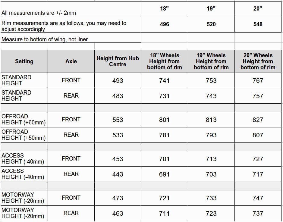
1. Таблица высоты калибровки пневмоподвески
2. Пособие по пневматической подвеске
yadi.sk/i/SlP44D9L3E4BLt
3. Электрическая библиотека (расшифровки разъемов, проводов и т.д.)
yadi.sk/i/l7WK4EdK3E4BVT
4. WORKSHOP MANUAL — SYSTEM DESCRIPTION AND OPERATION
— на русском
yadi.sk/i/fLlKPPD33E4Bs3
— на английском
yadi.sk/i/9cPTxEYp3E4C6X
5. Руководство по ремонту LRL0477RU
yadi.sk/i/vpPLjRsP3E4CAT
6. Руководство по ремонту с электросхемами (скан книги)
yadi.sk/i/wy00p5NV3E4CHp
7. AUX MFD E53
yadi.sk/i/y89ESnJA3E4CN9
Page 1 — Electrical Library
Electrical LibraryNRRERL 28/11/01 10:02 am Page 1
Page 2 — ELECTRICAL LIBRARY
INTRODUCTIONRANGE ROVER 1.5Battery ChargingOnly recharge the battery with it removed from the vehicle. Always ensure any battery charging area is wel
Page 3
DESCRIPTION AND OPERATIONRANGE ROVER 4.75Light Check ModuleThe LCM (C2040) is located at the base of the RH ‘A’ post, and monitors the cond
Page 4 — CONTENTS
DESCRIPTION AND OPERATION4.76 RANGE ROVERBi-Xenon SystemPower DistributionFeed from the positive battery terminal (C0192) is supplied to fuse 53, fusi
Page 5
DESCRIPTION AND OPERATIONRANGE ROVER 4.77Headlamp Dipped BeamIn addition to the lamps outlined in the side lamps section, the LCM will provide feeds
Page 6
DESCRIPTION AND OPERATION4.78 RANGE ROVERAUTOMATIC HEADLAMP LEVELLINGDESCRIPTIONGeneralAutomatic headlamp levelling is only fitted to vehicles with bi
Page 7
DESCRIPTION AND OPERATIONRANGE ROVER 4.79ABS ECUThe ABS ECU (C0506) provides a vehicle speed signal to the headlamp levelling ECU (C1543) on a YW wir
Page 8
DESCRIPTION AND OPERATION4.80 RANGE ROVERFOG LAMPSDESCRIPTIONGeneralOperation of both the front and rear fog lamps is controlled by the Light Check Mo
Page 9
DESCRIPTION AND OPERATIONRANGE ROVER 4.81Rear Fog LampsPower DistributionFeed from the positive battery terminal (C0192) is supplied to fusible link
Page 10 — INTRODUCTION
DESCRIPTION AND OPERATION4.82 RANGE ROVERDIRECTION INDICATOR/HAZARD WARNING LAMPSDESCRIPTIONGeneralOperation of the direction indicator lamps is contr
Page 11
DESCRIPTION AND OPERATIONRANGE ROVER 4.83RH TurnThe LCM (C2040) monitors the condition of the column mounted direction indicator switch (C1832) by pr
Page 12
DESCRIPTION AND OPERATION4.84 RANGE ROVERINTERIOR LAMPSDESCRIPTIONGeneralOperation of the interior lamps is controlled by the Body Control Unit (BCU)
Page 13
INTRODUCTION1.6 RANGE ROVERABBREVIATIONSGeneralAAmpereABS Anti-lock Braking System ac Alternating currentA/C Air ConditioningATC Automatic Temperatur
Page 14
DESCRIPTION AND OPERATIONRANGE ROVER 4.85Body Control Unit (BCU)The BCU (C0662) monitors the condition of all four doors and provides feeds to the fo
Page 15
DESCRIPTION AND OPERATION4.86 RANGE ROVERGlove Box LampThe BCU (C0662) monitors the condition of the glove box switch (C0227) by providing a feed on a
Page 16
DESCRIPTION AND OPERATIONRANGE ROVER 4.87INTERIOR ILLUMINATIONDESCRIPTIONGeneralOperation of the interior illumination LED’s and lamps is contro
Page 17
DESCRIPTION AND OPERATION4.88 RANGE ROVERLight Check Module (LCM)When the LCM (C2039) senses that the ignition switch is in either the auxiliary or ig
Page 18 — FUSE DETAILS
DESCRIPTION AND OPERATIONRANGE ROVER 4.89All the above are earthed on N wires. The LCM also provides a feed to the following LED’s on SR wires:l
Page 19
DESCRIPTION AND OPERATION4.90 RANGE ROVERINSTRUMENTSDESCRIPTIONGeneralThe instrument pack is a totally electronic device which receives analogue or di
Page 20
DESCRIPTION AND OPERATIONRANGE ROVER 4.91Analogue InstrumentsSpeedometerThe ABS ECU (C0506) provides the instrument pack (C0230) a pulsed signal on a
Page 21
DESCRIPTION AND OPERATION4.92 RANGE ROVERHORNSDESCRIPTIONGeneralTwo horns are located behind the RH side of the front bumper. Operation of the horns i
Page 22
DESCRIPTION AND OPERATIONRANGE ROVER 4.93CLOCKDESCRIPTIONGeneralThe analogue clock is mounted on the passenger side of the centre console, and is ill
Page 23
DESCRIPTION AND OPERATION4.94 RANGE ROVERCIGAR LIGHTERSDESCRIPTIONGeneralTwo cigar lighters are fitted to Range Rover. The front cigar lighter is loca
Page 24 — EARTH POINTS AND HEADERS
INTRODUCTIONRANGE ROVER 1.7HeVAC Heating, Ventilation and Air ConditioningHO2S Heated Oxygen SensorHDC Hill Descent Control HFS Heated Front Screen H
Page 25
DESCRIPTION AND OPERATIONRANGE ROVER 4.95ACCESSORY SOCKETSDESCRIPTIONGeneralTwo accessory sockets are fitted to Range Rover. The front accessory sock
Page 26
DESCRIPTION AND OPERATION4.96 RANGE ROVERTRAILER SOCKETDESCRIPTIONGeneralThe trailer socket is mounted at the rear of the vehicle, and receives inputs
Page 27
DESCRIPTION AND OPERATIONRANGE ROVER 4.97RH Tail LampWhen the LCM (C0937) detects that side or headlamps have been selected, it provides a feed to th
Page 28
DESCRIPTION AND OPERATION4.98 RANGE ROVERAUDIO SYSTEM – LOW LINEDESCRIPTIONGeneralFor a detailed description of the audio systems fitted to New Range
Page 29
DESCRIPTION AND OPERATIONRANGE ROVER 4.99AUDIO SYSTEM – MID-LINEDESCRIPTIONGeneralFor a detailed description of the audio systems fitted to New Range
Page 30
DESCRIPTION AND OPERATION4.100 RANGE ROVERAUDIO SYSTEM – HIGH LINEDESCRIPTIONGeneralFor a detailed description of the audio systems fitted to New Rang
Page 31
DESCRIPTION AND OPERATIONRANGE ROVER 4.101SATELLITE NAVIGATION SYSTEMDESCRIPTIONGeneralFor a detailed description of the satellite navigation system
Page 32
DESCRIPTION AND OPERATION4.102 RANGE ROVERSATELLITE NAVIGATION SYSTEM – NASDESCRIPTIONGeneralFor a detailed description of the satellite navigation sy
Page 33
DESCRIPTION AND OPERATIONRANGE ROVER 4.103TELEPHONEDESCRIPTIONGeneralFor a detailed description of the telephone systems fitted to New Range Rover, r
Page 34
DESCRIPTION AND OPERATION4.104 RANGE ROVERTELEPHONE – HANDS FREEDESCRIPTIONGeneralFor a detailed description of the telephone systems fitted to New Ra
Page 35
INTRODUCTION1.8 RANGE ROVERHOW TO USE THIS DOCUMENTFuse DetailsContains information on fuse functions and values and should be used together with the
Page 36
DESCRIPTION AND OPERATIONRANGE ROVER 4.105TELEPHONE – NASDESCRIPTIONGeneralFor a detailed description of the telephone systems fitted to New Range Ro
Page 37
DESCRIPTION AND OPERATION4.106 RANGE ROVERFUEL PUMPDESCRIPTIONTd6The fuel system on Td6 vehicles features three fuel pumps. A primary fuel pump is mou
Page 38
DESCRIPTION AND OPERATIONRANGE ROVER 4.107V8Power DistributionFeed from the positive battery terminal (C0192) is supplied to fusible link 2 and fusib
Page 39
DESCRIPTION AND OPERATION4.108 RANGE ROVERROTARY COUPLERDESCRIPTIONGeneralThe rotary coupler is a rotating link harness, acting as a bridge between th
Page 40
DESCRIPTION AND OPERATIONRANGE ROVER 4.109Driver AirbagFor detailed information on driver airbag operation, refer to the Supplementary Restraint Sys
Page 41
DESCRIPTION AND OPERATION4.110 RANGE ROVERPARK DISTANCE CONTROL (PDC)DESCRIPTIONGeneralPark Distance Control (PDC) provides an audible warning to the
Page 42
DESCRIPTION AND OPERATIONRANGE ROVER 4.111RH Inner SensorThe PDC ECU (C0958) provides a feed to the RH inner PDC sensor (C0965) on a GS wire. An eart
Page 43
DESCRIPTION AND OPERATION4.112 RANGE ROVERLH Outer SensorThe PDC ECU (C1457) provides a feed to the LH outer PDC sensor (C0402) on a GB wire. An earth
Page 44
DESCRIPTION AND OPERATIONRANGE ROVER 4.113TYRE PRESSURE MONITORING (TPM)DESCRIPTIONGeneralThe Tyre Pressure Monitoring (TPM) system continuously moni
Page 45
DESCRIPTION AND OPERATION4.114 RANGE ROVERSTEERING COLUMNDESCRIPTIONGeneralThe steering column fitted to New Range Rover features fully electrical adj
Page 46
INTRODUCTIONRANGE ROVER 1.91. Cav: The connector pin (cavity) number.2. Col: The colour of wire populating the connector pin.3. Cct: Identifies th
Page 47
DESCRIPTION AND OPERATIONRANGE ROVER 4.115Memory Steering ColumnPower DistributionFeed from the positive battery terminal (C0192) is supplied to the
Page 48
DESCRIPTION AND OPERATION4.116 RANGE ROVERSteering Wheel HeaterPower DistributionFeed from the positive battery terminal (C0192) is supplied to the st
Page 49
DESCRIPTION AND OPERATIONRANGE ROVER 4.117AIR SUSPENSIONDESCRIPTIONGeneralThe main function of the four wheel air suspension system is to maintain th
Page 50
DESCRIPTION AND OPERATION4.118 RANGE ROVERAir Suspension ECUThe air suspension ECU (C0867) is located behind the LH side of the fascia, and is connect
Page 51
DESCRIPTION AND OPERATIONRANGE ROVER 4.119RH Rear Height SensorThe air suspension ECU (C0867) provides a feed to the RH rear height sensor (C1698) on
Page 52 — + DOOR MIRRORS
DESCRIPTION AND OPERATION4.120 RANGE ROVERValve BlockThe valve block contains five solenoid valves which control the air supply as follows:RH FrontIf
Page 53
CONNECTORRANGE ROVER 5.1CONNECTORCIRCUIT REFERENCE NUMBERSCONNECTOR APPLICABILITYGeneralThe following table lists the circuit reference numbers again
Page 54
CONNECTOR5.2 RANGE ROVER30 Auxiliary Module (Europe)31 Auxiliary Module (NAS)
Page 55
CONNECTOR DETAILS C0001RANGE ROVERCONNECTOR DETAILSRANGE ROVERC0001Description: Lamp-Direction indicator/hazard warning-Front-LHLocation: Front of veh
Page 56
C0002 CONNECTOR DETAILSRANGE ROVERC0002Description: Lamp-Direction indicator/hazard warning-Front-RHLocation: Front of vehicle — RH sideColour: BLACKG
Page 57
INTRODUCTION1.10 RANGE ROVERFAULT DIAGNOSISGeneralWhen diagnosing an electrical fault, follow the steps below:1. Read the circuit description appropri
Page 58
CONNECTOR DETAILS C0003RANGE ROVERC0003Description: Horn (s)Location: Behind RH side of front bumperColour: GREYGender: FemaleP6868C0004C0003Cav Col C
Page 59
C0004 CONNECTOR DETAILSRANGE ROVERC0004Description: Horn (s)Location: Behind RH side of front bumperColour: GREYGender: FemaleP6868C0004C0003Cav Col C
Page 60
CONNECTOR DETAILS C0005RANGE ROVERC0005Description: Cooling fanLocation: Front of engine compartment — centreColour: BLACKGender: FemaleP6864C0005C154
Page 61
C0007 CONNECTOR DETAILSRANGE ROVERC0007Description: Switch-BonnetLocation: Rear RH side of engine compartmentColour: BLACKGender: FemaleP6884C0666C050
Page 62
CONNECTOR DETAILS C0008RANGE ROVERC0008Description: Pump-Washer-WindscreenLocation: Front LH side of engine compartmentColour: BLACKGender: FemaleP685
Page 63
C0009 CONNECTOR DETAILSRANGE ROVERC0009Description: Headlamp-LHLocation: Front of vehicle — LH sideColour: BLACKGender: FemaleP6860C0009C0071Cav Col C
Page 64
CONNECTOR DETAILS C0011RANGE ROVERC0011Description: Headlamp-RHLocation: Front of vehicle — RH sideColour: BLACKGender: FemaleP6866C0011C0070C1341Cav
Page 65
C0012 CONNECTOR DETAILSRANGE ROVERC0012Description: Lamp-Side repeater-Front-RHLocation: Front of vehicle — RH sideColour: BLACKGender: FemaleP6871C00
Page 66
CONNECTOR DETAILS C0013RANGE ROVERC0013Description: Lamp-Side repeater-Front-LHLocation: Front of vehicle — LH sideColour: BLACKGender: FemaleP6873C00
Page 67
C0017 CONNECTOR DETAILSRANGE ROVERC0017Description: Header -EarthLocation: LH side of engine compartmentColour: TIN-PLATEGender: MaleP6857C0362C0551C0
Page 68
INTRODUCTIONRANGE ROVER 1.11WIRE COLOUR CODESGeneralThe following list contains wire colour codes used on the vehicle harness’s.Code ColourBBlac
Page 69
CONNECTOR DETAILS C0018RANGE ROVERC0018Description: Header -EarthLocation: Front RH side of engine compartmentColour: TIN-PLATEGender: MaleP6867C0018C
Page 70
C0021 CONNECTOR DETAILSRANGE ROVERC0021Description: Pump-Washer-Rear screenLocation: Front LH side of engine compartmentColour: BLACKGender: FemaleP68
Page 71
CONNECTOR DETAILS C0026RANGE ROVERC0026Description: Switch-Brake fluid levelLocation: Rear of engine compartmentColour: BLACKGender: FemaleP6884C0666C
Page 72
C0028 CONNECTOR DETAILSRANGE ROVERC0028Description: Switch-Ignition — V8Location: Beneath centre consoleColour: WHITEGender: FemaleP6913C0049C0672C002
Page 73
CONNECTOR DETAILS C0030RANGE ROVERC0030Description: Motor-Wiper-WindscreenLocation: Rear of engine compartmentColour: BLACKGender: FemaleP6884C0666C05
Page 74
C0040 CONNECTOR DETAILSRANGE ROVERC0040Description: Diagnostic socketLocation: Behind driver side of fasciaColour: BLACKGender: FemaleP6916C0040Cav Co
Page 75
CONNECTOR DETAILS C0041RANGE ROVERC0041Description: Switch-LightingLocation: Behind driver side of fasciaColour: BLACKGender: FemaleP6920C0041Cav Col
Page 76
C0049 CONNECTOR DETAILSRANGE ROVERC0049Description: Coil-TransponderLocation: Beneath centre consoleColour: BLACKGender: FemaleP6913C0049C0672C0028C00
Page 77
CONNECTOR DETAILS C0050RANGE ROVERC0050Description: Sensor-Pad wearLocation: Behind LH front wheel arch linerColour: BLACKGender: FemaleP6877C0516C005
Page 78 — + FUEL BURNING HEATER – V8
C0053 CONNECTOR DETAILSRANGE ROVERC0053Description: Alternator/generator — Td6Location: LH side of engineColour:Gender:P7027C1216C0053Cav Col Cct1G31G
Page 79
INTRODUCTION1.12 RANGE ROVER
Page 80
CONNECTOR DETAILS C0056RANGE ROVERC0056Description: Motor-Blower-FrontLocation: Behind centre of fasciaColour:Gender:Cav Col Cct1BGALL2RGALL
Page 81
C0059 CONNECTOR DETAILSRANGE ROVERC0059Description: ECU-Engine ImmobilisationLocation: Beneath centre consoleColour: BLACKGender: FemaleP6914C1664C005
Page 82
CONNECTOR DETAILS C0070RANGE ROVERC0070Description: Motor-Headlamp levelling-RHLocation: Front of vehicle — RH sideColour: NATURALGender: FemaleP6866C
Page 83
C0071 CONNECTOR DETAILSRANGE ROVERC0071Description: Motor-Headlamp levelling-LHLocation: Front of vehicle — LH sideColour: NATURALGender: FemaleP6860C
Page 84
CONNECTOR DETAILS C0074RANGE ROVERC0074Description: Cigar lighter illuminationLocation: Beneath centre consoleColour: WHITEGender: FemaleP6911C0089C00
Page 85
C0075 CONNECTOR DETAILSRANGE ROVERC0075Description: Switch-Brake pedalLocation: Driver’s footwellColour: NATURALGender: FemaleP6976C0075Cav Col C
Page 86
CONNECTOR DETAILS C0076RANGE ROVERC0076Description: Lamp-Footwell-Front-RHLocation: Behind footwell trim panel — RH sideColour: BLACKGender: FemaleP69
Page 87
C0077 CONNECTOR DETAILSRANGE ROVERC0077Description: Lamp-Footwell-Front-LHLocation: Behind footwell trim panel — LH sideColour: BLACKGender: FemaleP69
Page 88
CONNECTOR DETAILS C0082RANGE ROVERC0082Description: Rotary couplerLocation: Underside of steering columnColour: GREENGender: FemaleP6955C1393C0082C204
Page 89
C0086 CONNECTOR DETAILSRANGE ROVERC0086Description: Cigar lighterLocation: Beneath centre consoleColour: BLACKGender: FemaleP6911C0089C0086C0074Cav Co
Page 90
FUSE DETAILSRANGE ROVER 2.1FUSE DETAILSIntroductionFuses are mounted in one of three fuse boxes. The engine compartment fuse box is located in the en
Page 91
CONNECTOR DETAILS C0089RANGE ROVERC0089Description: Cigar lighterLocation: Beneath centre consoleColour: BLACKGender: FemaleP6911C0089C0086C0074Cav Co
Page 92
C0091 CONNECTOR DETAILSRANGE ROVERC0091Description: Switch-HandbrakeLocation: Beneath centre consoleColour: BRASSGender: EyeletP6910C0350C0942C2322C00
Page 93
CONNECTOR DETAILS C0096RANGE ROVERC0096Description: Switch-Hazard Warning and CDL MasterLocation: Behind centre consoleColour: BLACKGender: FemaleP692
Page 94
C0099 CONNECTOR DETAILSRANGE ROVERC0099Description: Switch-Ignition — Td6Location: Beneath centre consoleColour: BLACKGender: FemaleP6913C0049C0672C00
Page 95
CONNECTOR DETAILS C0114RANGE ROVERC0114Description: Pump-FuelLocation: Above fuel tankColour: BLACKGender: FemaleP7012C0114Cav Col Cct1WUALL2 NBY ALL3
Page 96
C0117 CONNECTOR DETAILSRANGE ROVERC0117Description: Main harness to tail door harnessLocation: Rear of luggage compartmentColour: BLACKGender: MaleP69
Page 97
CONNECTOR DETAILS C0119RANGE ROVERC0119Description: Lamp-Load space-RHLocation: RH side of tail doorColour: BLACKGender: FemaleP6984C0119Cav Col Cct1N
Page 98
C0120 CONNECTOR DETAILSRANGE ROVERC0120Description: Lamp-Load space-LHLocation: LH side of taildoorColour: BLACKGender: FemaleP6983C0120Cav Col Cct1NY
Page 99
CONNECTOR DETAILS C0121RANGE ROVERC0121Description: Lamp-Tail-LHLocation: LH rear of vehicleColour: BLACKGender: FemaleC0121P6962Cav Col Cct1UGALL2BUA
Page 100 — DESCRIPTION AND OPERATION
C0125 CONNECTOR DETAILSRANGE ROVERC0125Description: Lamp-Tail-RHLocation: RH rear of vehicleColour: BLACKGender: FemaleP6963C0125Cav Col Cct1UNALL2BUA
Page 101
FUSE DETAILS2.2 RANGE ROVERENGINE COMPARTMENT FUSE BOXFuse Rating Vehicle FunctionF1 30 A V8 ECM, EAT ECU.F1 30 A Td6 ECM.F2 30 A V8 Variable camshaft
Page 102
CONNECTOR DETAILS C0132RANGE ROVERC0132Description: Sensor-Fuel rail pressure — Td6Location: Centre rear of engineColour:Gender:P7028C0132C0216Cav Col
Page 103 — + BRAKE AND REVERSE LAMPS
C0147 CONNECTOR DETAILSRANGE ROVERC0147Description: Sensor-Engine coolant levelLocation: Front LH side of engine compartmentColour: BLACKGender: Femal
Page 104
CONNECTOR DETAILS C0149RANGE ROVERC0149Description: Sensor-Mass air flow (MAF) — V8Location: Front RH side of engineColour:Gender:C0149P7038Cav Col Cc
Page 105
C0149 CONNECTOR DETAILSRANGE ROVERC0149Description: Sensor-Mass air flow (MAF) — Td6Location: Top of engineColour:Gender:P7026C0176C0149Cav Col Cct1YU
Page 106
CONNECTOR DETAILS C0162RANGE ROVERC0162Description: Engine harness to main harness — Td6Location: Inside E-boxColour:Gender:P7022C0162C0909C1526C0190C
Page 107
C0162 CONNECTOR DETAILSRANGE ROVERC0162Description: Engine harness to main harness — V8Location: Inside E-boxColour:Gender:P7020C0162C0606C0332C2089C1
Page 108
CONNECTOR DETAILS C0168RANGE ROVERC0168Description: Sensor-Crankshaft position (CKP) — Td6Location: LH side of engineColour:Gender:C0168P7035Cav Col C
Page 109
C0169 CONNECTOR DETAILSRANGE ROVERC0169Description: Sensor-Engine coolant temperature (ECT) — Td6Location: Rear LH side of engineColour:Gender:C0169C2
Page 110
CONNECTOR DETAILS C0176RANGE ROVERC0176Description: Sensor-Camshaft position (CMP) — Td6Location: Top of engineColour:Gender:P7026C0176C0149Cav Col Cc
Page 111
C0179 CONNECTOR DETAILSRANGE ROVERC0179Description: Solenoid-Starter motor — Td6Location: LH side of engineColour:Gender:P7034C0823C0179C0178Cav Col C
Page 112
ELECTRICAL LIBRARYLRL 0453ENG(2)Published by Land Rover© Land Rover 2002All rights reserved. No part of this publication may be reproduced, stored in
Page 113
FUSE DETAILSRANGE ROVER 2.3PASSENGER COMPARTMENT FUSE BOXLink Rating Vehicle FunctionFL1 80 A All Heated front screen relay.FL2 60 A Td6 Ignition sw
Page 114
CONNECTOR DETAILS C0182RANGE ROVERC0182Description: Clutch-Compressor-Air conditioning (A/C) — V8Location: Lower RH front of engine compartmentColour:
Page 115
C0184 CONNECTOR DETAILSRANGE ROVERC0184Description: Sensor-Temperature-Fuel rail — Td6Location: LH side of engine compartmentColour:Gender:P7033C2303C
Page 116
CONNECTOR DETAILS C0187RANGE ROVERC0187Description: Switch-Oil pressureLocation: Front LH side of engine compartmentColour: BLACKGender: FemaleP6855C0
Page 117
C0191 CONNECTOR DETAILSRANGE ROVERC0191Description: Solenoid-EGR — Td6Location: LH side of engineColour:Gender:C0169C2262P7029C0191Cav Col Cct1RW32NS3
Page 118
CONNECTOR DETAILS C0193RANGE ROVERC0193Description: ECU-Electronic automatic transmissionLocation: Inside E-boxColour: BLUEGender: FemaleP6882C0448C21
Page 119
C0195 CONNECTOR DETAILSRANGE ROVERC0195Description: AccelerometerLocation: Beneath centre consoleColour: BLACKGender: FemaleP6915C0256C0360C0195Cav Co
Page 120
CONNECTOR DETAILS C0216RANGE ROVERC0216Description: Sensor-Boost pressure — Td6Location: Centre rear of engineColour:Gender:P7028C0132C0216Cav Col Cct
Page 121
C0230 CONNECTOR DETAILSRANGE ROVERC0230Description: Instrument PackLocation: Behind instrument packColour: BLACKGender: FemaleP6925C0233C0230C0234Cav
Page 122
CONNECTOR DETAILS C0232RANGE ROVERC0232Description: Clock-AnalogueLocation: Behind centre consoleColour: BLACKGender: FemaleP6926C0232C0700C1629C1630C
Page 123
C0233 CONNECTOR DETAILSRANGE ROVERC0233Description: Instrument PackLocation: Behind instrument packColour: BLACKGender: FemaleP6925C0233C0230C0234Cav
Page 124
FUSE DETAILS2.4 RANGE ROVERFuse Rating Vehicle FunctionF1 5 A All Instrument packF2 5 A All Heated rear screen relay, rear blower motor relay, seat he
Page 125
CONNECTOR DETAILS C0234RANGE ROVERC0234Description: Instrument PackLocation: Behind instrument packColour: GREYGender: FemaleP6925C0233C0230C0234Cav C
Page 126
C0243 CONNECTOR DETAILSRANGE ROVERC0243Description: Selector-Automatic transmissionLocation: Beneath centre consoleColour: BLACKGender: FemaleP6909C06
Page 127
CONNECTOR DETAILS C0244RANGE ROVERC0244Description: Gearbox — Td6Location: RH side of gearboxColour:Gender:C0244P7030Cav Col Cct1W32O32R253N33B34YU34Y
Page 128
C0245 CONNECTOR DETAILSRANGE ROVERC0245Description: Lamp-Automatic gearbox selector indicatorLocation: Beneath centre consoleColour: WHITEGender: Fema
Page 129
CONNECTOR DETAILS C0246RANGE ROVERC0246Description: Heated screen-FrontLocation: Behind RH side of fasciaColour: BLACKGender: MaleP6919C0246C2081Cav C
Page 130
C0247 CONNECTOR DETAILSRANGE ROVERC0247Description: Heated screen-FrontLocation: Behind LH side of fasciaColour: BLACKGender: MaleP6921C2051C0247Cav C
Page 131
CONNECTOR DETAILS C0249RANGE ROVERC0249Description: Heater-SeatLocation: Behind centre consoleColour: NATURALGender: FemaleP6926C0232C0700C1629C1630C0
Page 132
C0251 CONNECTOR DETAILSRANGE ROVERC0251Description: Air bag-PassengerLocation: Behind passenger side of fasciaColour: BLACKGender: MaleP6957C0251Cav C
Page 133 — + STEERING COLUMN
CONNECTOR DETAILS C0253RANGE ROVERC0253Description: Main harness to seat harnessLocation: Beneath RH seatColour: YELLOWGender: FemaleP6993C0253Cav Col
Page 134
C0255 CONNECTOR DETAILSRANGE ROVERC0255Description: Main harness to seat harnessLocation: Beneath LH seatColour: YELLOWGender: FemaleP6998C0662C0661C0
Page 135
FUSE DETAILSRANGE ROVER 2.5F34 7.5 A All HeVAC control module.F35 5 A All Centre console switch pack, Hill Descent Control switch.F36 5 A All Not use
Page 136
CONNECTOR DETAILS C0256RANGE ROVERC0256Description: DCU-AirbagLocation: Beneath centre consoleColour: NATURALGender: FemaleP6915C0256C0360C0195Cav Col
Page 137
C0274 CONNECTOR DETAILSRANGE ROVERC0274Description: Valve block-Air SuspensionLocation: Beneath vehicle — RH sideColour: BLACKGender: FemaleP7004C0770
Page 138
CONNECTOR DETAILS C0278RANGE ROVERC0278Description: Switch-Wash/wipe-WindscreenLocation: Top of steering columnColour: BLACKGender: FemaleP6952C0278C2
Page 139
C0286 CONNECTOR DETAILSRANGE ROVERC0286Description: HeaderLocation: Beneath front passenger’s seatColour:Gender:P6998C0662C0661C0660C0286C0255Cav
Page 140
CONNECTOR DETAILS C0304RANGE ROVERC0304Description: Motor-Window-RearLocation: Behind rear door trim panelColour: BLACKGender: FemaleC0304P6905Cav Col
Page 141
C0310 CONNECTOR DETAILSRANGE ROVERC0310Description: Speaker-Low range-Rear-RHLocation: Behind rear door trim panelColour: BLACKGender: FemaleP6904C031
Page 142
CONNECTOR DETAILS C0311RANGE ROVERC0311Description: Speaker-Mid range-Rear-RHLocation: Behind rear door trim panelColour: WHITEGender: FemaleP6903C073
Page 143
C0322 CONNECTOR DETAILSRANGE ROVERC0322Description: Passenger door harness to main harnessLocation: Base of passenger side ‘A’ postColour: B
Page 144
CONNECTOR DETAILS C0331RANGE ROVERC0331Description: Engine control module (ECM)Location: Inside E-boxColour: BLACKGender: FemaleP6882C0448C2138C0193C0
Page 145
C0332 CONNECTOR DETAILSRANGE ROVERC0332Description: Engine control module (ECM) — V8Location: Inside E-boxColour:Gender:P7020C0162C0606C0332C2089C1895
Page 146 — CONNECTOR
FUSE DETAILS2.6 RANGE ROVERREAR FUSE BOXFuse Rating Vehicle FunctionF1 20 A All Front cigar lighter, Rear cigar lighter, Front accessory socket.F2 25
Page 147
CONNECTOR DETAILS C0332RANGE ROVERC0332Description: Engine control module (ECM) — Td6Location: Inside E-boxColour: BLUEGender: MaleP7020C0162C0606C033
Page 148 — CONNECTOR DETAILS C0001
C0333 CONNECTOR DETAILSRANGE ROVERC0333Description: Main harness to air suspension harnessLocation: Behind RH front wheel arch linerColour: BLACKGende
Page 149 — C0002 CONNECTOR DETAILS
CONNECTOR DETAILS C0336RANGE ROVERC0336Description: Door harness to main harnessLocation: Base of driver side ‘A’ postColour: BLACKGender: F
Page 150 — CONNECTOR DETAILS C0003
C0350 CONNECTOR DETAILSRANGE ROVERC0350Description: Socket-Accessory-RearLocation: Luggage compartment — RH sideColour:Gender:P6959C2047C0350Cav Col C
Page 151 — C0004 CONNECTOR DETAILS
CONNECTOR DETAILS C0350RANGE ROVERC0350Description: Socket-Accessory-FrontLocation: Beneath centre consoleColour: WHITEGender: FemaleP6910C0350C0942C2
Page 152 — CONNECTOR DETAILS C0005
C0353 CONNECTOR DETAILSRANGE ROVERC0353Description: Mirror-Door-Passenger sideLocation: Behind passenger’s door trim panelColour:Gender:P6892C053
Page 153 — C0007 CONNECTOR DETAILS
CONNECTOR DETAILS C0355RANGE ROVERC0355Description: Lamp-Interior-FrontLocation: Front of headlining in the centreColour: BLACKGender: FemaleP6932C035
Page 154 — CONNECTOR DETAILS C0008
C0357 CONNECTOR DETAILSRANGE ROVERC0357Description: Lamp-Interior-RearLocation: Behind centre headliningColour: NATURALGender: FemaleP6935C0357C0359Ca
Page 155 — C0009 CONNECTOR DETAILS
CONNECTOR DETAILS C0359RANGE ROVERC0359Description: Sensor-VolumetricLocation: Behind centre headliningColour: BLACKGender: FemaleP6935C0357C0359Cav C
Page 156 — CONNECTOR DETAILS C0011
C0360 CONNECTOR DETAILSRANGE ROVERC0360Description: Earth-SRSLocation: Beneath centre consoleColour: TIN-PLATEGender: EyeletP6915C0256C0360C0195Cav Co
Page 157 — C0012 CONNECTOR DETAILS
EARTH POINTS AND HEADERSRANGE ROVER 3.1EARTH POINTS AND HEADERSGeneralThe following illustration indicates the general position of each earth point a
Page 158 — CONNECTOR DETAILS C0013
CONNECTOR DETAILS C0362RANGE ROVERC0362Description: Earth-ABSLocation: Rear LH side of engine compartmentColour: TIN-PLATEGender: EyeletP6857C0362C055
Page 159 — C0017 CONNECTOR DETAILS
C0363 CONNECTOR DETAILSRANGE ROVERC0363Description: Switch-Sunroof-FrontLocation: Front of headlining in the centreColour: BLACKGender: FemaleP6931C13
Page 160 — CONNECTOR DETAILS C0018
CONNECTOR DETAILS C0369RANGE ROVERC0369Description: Speaker-PDCLocation: Driver’s footwellColour: NATURALGender: FemaleP6950C1352C1577C0076C0405C
Page 161 — C0021 CONNECTOR DETAILS
C0381 CONNECTOR DETAILSRANGE ROVERC0381Description: Heated rear window (HRW)Location: LH side of taildoorColour: BLACKGender: FemaleP6987C0381Cav Col
Page 162 — CONNECTOR DETAILS C0026
CONNECTOR DETAILS C0382RANGE ROVERC0382Description: Heated rear window (HRW)Location: RH side of tail doorColour: BLACKGender: FemaleP6988C0382Cav Col
Page 163 — C0028 CONNECTOR DETAILS
C0383 CONNECTOR DETAILSRANGE ROVERC0383Description: Motor-Lock-Tail doorLocation: Centre of taildoor, behind trim panelColour: BLACKGender: FemaleP698
Page 164 — CONNECTOR DETAILS C0030
CONNECTOR DETAILS C0384RANGE ROVERC0384Description: Tail door harness to main harnessLocation: Rear of luggage compartmentColour: BLACKGender: FemaleP
Page 165 — C0040 CONNECTOR DETAILS
C0388 CONNECTOR DETAILSRANGE ROVERC0388Description: Motor-Wiper-Rear screenLocation: Centre of taildoor, behind trim panelColour: BLACKGender: FemaleP
Page 166 — CONNECTOR DETAILS C0041
CONNECTOR DETAILS C0400RANGE ROVERC0400Description: Sensor-PDC-Inner-Front-LHLocation: Behind LH side of front bumperColour: GREYGender: FemaleP6861C0
Page 167 — C0049 CONNECTOR DETAILS
C0401 CONNECTOR DETAILSRANGE ROVERC0401Description: Sensor-PDC-Inner-Front-RHLocation: Behind RH side of front bumperColour: GREYGender: FemaleP6862C0
Page 169 — C0053 CONNECTOR DETAILS
CONNECTOR DETAILS C0402RANGE ROVERC0402Description: Sensor-PDC-Outer-Front-LHLocation: Behind LH side of front bumperColour: GREYGender: FemaleP6861C0
Page 170 — CONNECTOR DETAILS C0056
C0403 CONNECTOR DETAILSRANGE ROVERC0403Description: Sensor-PDC-Outer-Front-RHLocation: Behind RH side of front bumperColour: GREYGender: FemaleP6862C0
Page 171 — C0059 CONNECTOR DETAILS
CONNECTOR DETAILS C0405RANGE ROVERC0405Description: Speaker-PDCLocation: Driver’s footwellColour: BLACKGender: FemaleP6950C1352C1577C0076C0405C03
Page 172 — CONNECTOR DETAILS C0070
C0416 CONNECTOR DETAILSRANGE ROVERC0416Description: Sensor-Temperature-Heater coolantLocation: Lower RH front of engine compartmentColour:Gender:P6865
Page 173 — C0071 CONNECTOR DETAILS
CONNECTOR DETAILS C0420RANGE ROVERC0420Description: Air suspension harness to main harnessLocation: Behind RH front wheel arch linerColour: BLACKGende
Page 174 — CONNECTOR DETAILS C0074
C0435 CONNECTOR DETAILSRANGE ROVERC0435Description: Main harness to door harnessLocation: LH ‘C’ postColour: BLACKGender: MaleP6908C0435C080
Page 175 — C0075 CONNECTOR DETAILS
CONNECTOR DETAILS C0436RANGE ROVERC0436Description: Main harness to door harnessLocation: RH ‘C’ postColour: BLACKGender: MaleP6907C0803C043
Page 176 — CONNECTOR DETAILS C0076
C0442 CONNECTOR DETAILSRANGE ROVERC0442Description: Motor-Door lock-RearLocation: Behind rear door trim panelColour: BLUEGender: FemaleP6906C0442Cav C
Page 177 — C0077 CONNECTOR DETAILS
CONNECTOR DETAILS C0448RANGE ROVERC0448Description: Main harness to engine harness — V8Location: Inside E-boxColour: NATURALGender: MaleP6882C0448C213
Page 178 — CONNECTOR DETAILS C0082
C0455 CONNECTOR DETAILSRANGE ROVERC0455Description: Lamp-Reverse-RHLocation: RH rear of vehicleColour:Gender:P6966C0455Cav Col Cct1N32WY3
Page 179 — C0086 CONNECTOR DETAILS
DESCRIPTION AND OPERATIONRANGE ROVER 4.1DESCRIPTION AND OPERATIONANTI-THEFT ALARM AND CENTRAL DOOR LOCKING (CDL)DESCRIPTIONAnti-Theft AlarmThe anti-t
Page 180 — CONNECTOR DETAILS C0089
CONNECTOR DETAILS C0459RANGE ROVERC0459Description: Main harness to door harnessLocation: Base of driver side ‘A’ postColour: BLACKGender: M
Page 181 — C0091 CONNECTOR DETAILS
C0463 CONNECTOR DETAILSRANGE ROVERC0463Description: Main harness to door harnessLocation: Base of passenger side ‘A’ postColour: BLACKGender
Page 182 — CONNECTOR DETAILS C0096
CONNECTOR DETAILS C0472RANGE ROVERC0472Description: Lamp-Reverse-LHLocation: LH rear of vehicleColour:Gender:P6967C0472Cav Col Cct1N32WY3
Page 183 — C0099 CONNECTOR DETAILS
C0473 CONNECTOR DETAILSRANGE ROVERC0473Description: Main harness to trailer harnessLocation: Rear of luggage compartment — RH sideColour: NATURALGende
Page 184 — CONNECTOR DETAILS C0114
CONNECTOR DETAILS C0476RANGE ROVERC0476Description: Glow plug — Td6Location: LH side of engineColour:Gender:C1501C1500C0479C0478C0477C0476P7032Cav Col
Page 185 — C0117 CONNECTOR DETAILS
C0477 CONNECTOR DETAILSRANGE ROVERC0477Description: Glow plug — Td6Location: LH side of engineColour:Gender:C1501C1500C0479C0478C0477C0476P7032Cav Col
Page 186 — CONNECTOR DETAILS C0119
CONNECTOR DETAILS C0478RANGE ROVERC0478Description: Glow plug — Td6Location: LH side of engineColour:Gender:C1501C1500C0479C0478C0477C0476P7032Cav Col
Page 187 — C0120 CONNECTOR DETAILS
C0479 CONNECTOR DETAILSRANGE ROVERC0479Description: Glow plug — Td6Location: LH side of engineColour:Gender:C1501C1500C0479C0478C0477C0476P7032Cav Col
Page 188 — CONNECTOR DETAILS C0121
CONNECTOR DETAILS C0502RANGE ROVERC0502Description: Sensor-ABS-Rear-LHLocation: Below LH rear wheelarchColour: BLUEGender: FemaleP7009C2028 C0502Cav C
Page 189 — C0125 CONNECTOR DETAILS
C0503 CONNECTOR DETAILSRANGE ROVERC0503Description: Sensor-ABS-Rear-RHLocation: Below RH rear wheelarchColour: BLUEGender: FemaleP7006C0968C0503Cav Co
Page 190 — CONNECTOR DETAILS C0132
DESCRIPTION AND OPERATION4.2 RANGE ROVERCentral Door Locking (CDL) and SuperlockingTwo levels of locking are available; Central Door Locking (CDL) and
Page 191 — C0147 CONNECTOR DETAILS
CONNECTOR DETAILS C0506RANGE ROVERC0506Description: ECU-ABSLocation: Rear LH side of engine compartmentColour:Gender:P6879C0506C2036Cav Col Cct1NALL2R
Page 192 — CONNECTOR DETAILS C0149
C0507 CONNECTOR DETAILSRANGE ROVERC0507Description: Pump-Return-ABSLocation: Rear of engine compartmentColour: BLACKGender: FemaleP6884C0666C0507C0026
Page 193 — C0149 CONNECTOR DETAILS
CONNECTOR DETAILS C0513RANGE ROVERC0513Description: Lamp-Fog-Front-RHLocation: Front of vehicle — RH sideColour: GREYGender: FemaleP6851C0513Cav Col C
Page 194 — CONNECTOR DETAILS C0162
C0514 CONNECTOR DETAILSRANGE ROVERC0514Description: Lamp-Fog-Front-LHLocation: Front of vehicle — LH sideColour: GREYGender: FemaleP6852C0514Cav Col C
Page 195 — C0162 CONNECTOR DETAILS
CONNECTOR DETAILS C0516RANGE ROVERC0516Description: Sensor-ABS-Front-LHLocation: Behind LH front wheel arch linerColour: BLUEGender: FemaleP6877C0516C
Page 196 — CONNECTOR DETAILS C0168
C0517 CONNECTOR DETAILSRANGE ROVERC0517Description: Sensor-ABS-Front-RHLocation: Behind RH front wheel arch linerColour: BLUEGender: FemaleP6874C0517C
Page 197 — C0169 CONNECTOR DETAILS
CONNECTOR DETAILS C0522RANGE ROVERC0522Description: Fuel injector-No.1 — Td6Location: Top of engineColour: BLACKGender: FemaleC0526C0524C0523C0525P702
Page 198 — CONNECTOR DETAILS C0176
C0523 CONNECTOR DETAILSRANGE ROVERC0523Description: Fuel injector-No.2 — Td6Location: Top of engineColour: BLACKGender: FemaleC0526C0524C0523C0525P702
Page 199 — C0179 CONNECTOR DETAILS
CONNECTOR DETAILS C0524RANGE ROVERC0524Description: Fuel injector-No.3 — Td6Location: Top of engineColour: BLACKGender: FemaleC0526C0524C0523C0525P702
Page 200 — CONNECTOR DETAILS C0182
C0525 CONNECTOR DETAILSRANGE ROVERC0525Description: Fuel injector-No.4 — Td6Location: Top of engineColour: BLACKGender: FemaleC0526C0524C0523C0525P702
Page 201 — C0184 CONNECTOR DETAILS
DESCRIPTION AND OPERATIONRANGE ROVER 4.3OPERATIONAnti-Theft AlarmPower DistributionFeed from the positive battery terminal (C0192) is supplied to fus
Page 202 — CONNECTOR DETAILS C0187
CONNECTOR DETAILS C0526RANGE ROVERC0526Description: Fuel injector-No.5 — Td6Location: Top of engineColour: BLACKGender: FemaleC0526C0524C0523C0525P702
Page 203 — C0191 CONNECTOR DETAILS
C0527 CONNECTOR DETAILSRANGE ROVERC0527Description: Fuel injector-No.6Location: Top of engineColour: BLACKGender: FemaleC0526C0524C0523C0525P7025C0527
Page 204 — CONNECTOR DETAILS C0193
CONNECTOR DETAILS C0530RANGE ROVERC0530Description: Speakers-High RangeLocation: Behind driver’s door trim panelColour:Gender:P6887C0530C0599Cav
Page 205 — C0195 CONNECTOR DETAILS
C0531 CONNECTOR DETAILSRANGE ROVERC0531Description: Speakers-High RangeLocation: Behind passenger’s door trim panelColour:Gender:P6892C0531C0353C
Page 206 — CONNECTOR DETAILS C0216
CONNECTOR DETAILS C0537RANGE ROVERC0537Description: Lamp-Side-Front-RHLocation: Behind RH side of front bumperColour:Gender:P6863C0002C0537Cav Col Cct
Page 207 — C0230 CONNECTOR DETAILS
C0538 CONNECTOR DETAILSRANGE ROVERC0538Description: Lamp-Side-Front-LHLocation: Behind LH side of front bumperColour:Gender:P6853C0001C0538Cav Col Cct
Page 208 — CONNECTOR DETAILS C0232
CONNECTOR DETAILS C0546RANGE ROVERC0546Description: ECU-Delay-Windscreen wiperLocation: Rear LH side of engine compartmentColour: BLACKGender: FemaleP
Page 209 — C0233 CONNECTOR DETAILS
C0550 CONNECTOR DETAILSRANGE ROVERC0550Description: EarthLocation: Front RH side of engine compartmentColour: TIN-PLATEGender: MaleP6867C0018C0550Cav
Page 210 — CONNECTOR DETAILS C0234
CONNECTOR DETAILS C0551RANGE ROVERC0551Description: Header -EarthLocation: Front LH side of engine compartmentColour: TIN-PLATEGender: MaleP6857C0362C
Page 211 — C0243 CONNECTOR DETAILS
C0552 CONNECTOR DETAILSRANGE ROVERC0552Description: Header -EarthLocation: Base of RH ‘A’ postColour: TIN-PLATEGender: MaleP6974C0552Cav Col
Page 212 — CONNECTOR DETAILS C0244
DESCRIPTION AND OPERATION4.4 RANGE ROVERVolumetric SensorThe volumetric sensor monitors the inside of the vehicle by emitting a series of ultrasound p
Page 213 — C0245 CONNECTOR DETAILS
CONNECTOR DETAILS C0553RANGE ROVERC0553Description: Header -EarthLocation: Beneath LH seatColour: TIN-PLATEGender: MaleP7000C0553Cav Col Cct0NALL
Page 214 — CONNECTOR DETAILS C0246
C0554 CONNECTOR DETAILSRANGE ROVERC0554Description: Header -EarthLocation: Beneath footwell carpet — LH sideColour: TIN-PLATEGender: MaleP6977C0554C15
Page 215 — C0247 CONNECTOR DETAILS
CONNECTOR DETAILS C0555RANGE ROVERC0555Description: Header -EarthLocation: Luggage compartment — RH sideColour: TIN-PLATEGender: MaleP6990C0555C0706Ca
Page 216 — CONNECTOR DETAILS C0249
C0556 CONNECTOR DETAILSRANGE ROVERC0556Description: EarthLocation: Front LH side of engine compartmentColour: TIN-PLATEGender: EyeletP6855C0556C0187Ca
Page 217 — C0251 CONNECTOR DETAILS
CONNECTOR DETAILS C0559RANGE ROVERC0559Description: EarthLocation: RH side of engine compartmentColour: TIN-PLATEGender: EyeletP7024C0559C0629Cav Col
Page 218 — CONNECTOR DETAILS C0253
C0570 CONNECTOR DETAILSRANGE ROVERC0570Description: Holder-Fuse — Td6Location: Inside E-boxColour:Gender:P7022C0162C0909C1526C0190C0189C0570C1895Cav C
Page 219 — C0255 CONNECTOR DETAILS
CONNECTOR DETAILS C0570RANGE ROVERC0570Description: Holder-Fuse — V8Location: Inside E-boxColour:Gender:P7022C0162C0909C1526C0190C0189C0570C1895Cav Co
Page 220 — CONNECTOR DETAILS C0256
C0580 CONNECTOR DETAILSRANGE ROVERC0580Description: Fuse box-Passenger compartmentLocation: Behind gloveboxColour:Gender:P6956C0583C0580C0632C0585C058
Page 221 — C0274 CONNECTOR DETAILS
CONNECTOR DETAILS C0581RANGE ROVERC0581Description: Fuse box-Passenger compartmentLocation: Behind gloveboxColour: BLACKGender: FemaleP6956C0583C0580C
Page 222 — CONNECTOR DETAILS C0278
C0582 CONNECTOR DETAILSRANGE ROVERC0582Description: Fuse box-Passenger compartmentLocation: Behind gloveboxColour:Gender:P6956C0583C0580C0632C0585C058
Page 224 — CONNECTOR DETAILS C0304
DESCRIPTION AND OPERATIONRANGE ROVER 4.5Battery Backed-Up Sounder (BBUS)The BBUS (C0666) is mounted adjacent the brake servo, and is provided a const
Page 225 — C0310 CONNECTOR DETAILS
CONNECTOR DETAILS C0583RANGE ROVERC0583Description: Fuse box-Passenger compartmentLocation: Behind gloveboxColour: BLUEGender: FemaleP6956C0583C0580C0
Page 226 — CONNECTOR DETAILS C0311
C0584 CONNECTOR DETAILSRANGE ROVERC0584Description: Fuse box-Passenger compartmentLocation: Behind gloveboxColour: NATURALGender: FemaleP6956C0583C058
Page 227 — C0322 CONNECTOR DETAILS
CONNECTOR DETAILS C0585RANGE ROVERC0585Description: Fuse box-Passenger compartmentLocation: Behind gloveboxColour: BLACKGender: FemaleP6956C0583C0580C
Page 228 — CONNECTOR DETAILS C0331
C0586 CONNECTOR DETAILSRANGE ROVERC0586Description: Fuse box-Passenger compartmentLocation: Behind gloveboxColour: BLACKGender: FemaleP6956C0583C0580C
Page 229 — C0332 CONNECTOR DETAILS
CONNECTOR DETAILS C0587RANGE ROVERC0587Description: Fuse box-Passenger compartmentLocation: Behind gloveboxColour: NATURALGender: FemaleP6956C0583C058
Page 230 — CONNECTOR DETAILS C0332
C0588 CONNECTOR DETAILSRANGE ROVERC0588Description: Fuse box-Passenger compartmentLocation: Behind passenger compartment fuseboxColour:Gender:C0592C05
Page 231 — C0333 CONNECTOR DETAILS
CONNECTOR DETAILS C0589RANGE ROVERC0589Description: Fuse box-Passenger compartmentLocation: Behind passenger compartment fuseboxColour:Gender:C0592C05
Page 232 — CONNECTOR DETAILS C0336
C0590 CONNECTOR DETAILSRANGE ROVERC0590Description: Fuse box-Passenger compartmentLocation: Behind passenger compartment fuseboxColour:Gender:C0592C05
Page 233 — C0350 CONNECTOR DETAILS
CONNECTOR DETAILS C0591RANGE ROVERC0591Description: Fuse box-Passenger compartmentLocation: Behind passenger compartment fuseboxColour: TIN-PLATEGende
Page 234 — CONNECTOR DETAILS C0350
C0592 CONNECTOR DETAILSRANGE ROVERC0592Description: Fuse box-Passenger compartmentLocation: Behind passenger compartment fuseboxColour:Gender:C0592C05
Page 235 — C0353 CONNECTOR DETAILS
DESCRIPTION AND OPERATION4.6 RANGE ROVERCentral Door Locking (CDL)Power DistributionFeed from the positive battery terminal (C0192) is supplied to the
Page 236 — CONNECTOR DETAILS C0355
CONNECTOR DETAILS C0599RANGE ROVERC0599Description: Sensor-Anti-trap-DriverLocation: Behind driver’s door trim panelColour:Gender:P6887C0530C0599
Page 237 — C0357 CONNECTOR DETAILS
C0600 CONNECTOR DETAILSRANGE ROVERC0600Description: Sensor-Anti-trap-PassengerLocation: Behind passenger’s door trim panelColour:Gender:P6892C053
Page 238 — CONNECTOR DETAILS C0359
CONNECTOR DETAILS C0603RANGE ROVERC0603Description: Engine control module (ECM) — Td6Location: Inside E-boxColour:Gender:P7023C0604C0603C2138C1835C019
Page 239 — C0360 CONNECTOR DETAILS
C0603 CONNECTOR DETAILSRANGE ROVERC0603Description: Engine control module (ECM) — V8Location: Inside E-boxColour:Gender:P7039C0604C0603C0606C0332C0331
Page 240 — CONNECTOR DETAILS C0362
CONNECTOR DETAILS C0604RANGE ROVERC0604Description: Engine control module (ECM) — Td6Location: Inside E-boxColour:Gender:P7023C0604C0603C2138C1835C019
Page 241 — C0363 CONNECTOR DETAILS
C0604 CONNECTOR DETAILSRANGE ROVERC0604Description: Engine control module (ECM) — V8Location: Inside E-boxColour:Gender:P7039C0604C0603C0606C0332C0331
Page 242 — CONNECTOR DETAILS C0369
CONNECTOR DETAILS C0606RANGE ROVERC0606Description: Engine control module (ECM) — Td6Location: Inside E-boxColour:Gender:P7023C0604C0603C2138C1835C019
Page 243 — C0381 CONNECTOR DETAILS
C0606 CONNECTOR DETAILSRANGE ROVERC0606Description: Engine control module (ECM) — V8Location: Inside E-boxColour:Gender:P7020C0162C0606C0332C2089C1895
Page 245 — C0383 CONNECTOR DETAILS
C0615 CONNECTOR DETAILSRANGE ROVERC0615Description: Switch-Tail door openLocation: Centre of taildoor, behind trim panelColour:Gender:P6968C2052C0615C
Page 246 — CONNECTOR DETAILS C0384
DESCRIPTION AND OPERATIONRANGE ROVER 4.7Drivers DoorThe BCU controls operation of the drivers door lock via the drivers door module. The drivers door
Page 247 — C0388 CONNECTOR DETAILS
CONNECTOR DETAILS C0617RANGE ROVERC0617Description: Motor-Lock-Tail doorLocation: LH side of taildoorColour:Gender:P6969C0617Cav Col Cct1N32UW3
Page 248 — CONNECTOR DETAILS C0400
C0620 CONNECTOR DETAILSRANGE ROVERC0620Description: Sensor-Low washer fluid levelLocation: Front LH side of engine compartmentColour: BLACKGender: Fem
Page 249 — C0401 CONNECTOR DETAILS
CONNECTOR DETAILS C0629RANGE ROVERC0629Description: Solenoid valve-Boost Control — Td6Location: RH side of engine compartmentColour:Gender:P7024C0559C
Page 250 — CONNECTOR DETAILS C0402
C0642 CONNECTOR DETAILSRANGE ROVERC0642Description: Sensor-Heated oxygen (HO2S)Location: Beneath centre of vehicleColour:Gender:P6940C0642Cav Col Cct1
Page 251 — C0403 CONNECTOR DETAILS
CONNECTOR DETAILS C0643RANGE ROVERC0643Description: Sensor-Heated oxygen (HO2S)Location: Beneath centre of vehicleColour:Gender:P6941C0643C1858Cav Col
Page 252 — CONNECTOR DETAILS C0405
C0644 CONNECTOR DETAILSRANGE ROVERC0644Description: Sensor-Heated oxygen (HO2S)Location: Beneath centre of vehicleColour:Gender:C0644P6943Cav Col Cct1
Page 253 — C0416 CONNECTOR DETAILS
CONNECTOR DETAILS C0645RANGE ROVERC0645Description: Sensor-Heated oxygen (HO2S)Location: Beneath centre of vehicleColour:Gender:P6942C0645C1544Cav Col
Page 254 — CONNECTOR DETAILS C0420
C0646 CONNECTOR DETAILSRANGE ROVERC0646Description: Fan-E-boxLocation: Inside E-boxColour: NATURALGender: FemaleP6882C0448C2138C0193C0331C1886C0646C21
Page 255 — C0435 CONNECTOR DETAILS
CONNECTOR DETAILS C0660RANGE ROVERC0660Description: Body control unit (BCU)Location: Beneath front passenger’s seatColour: GREYGender: FemaleP699
Page 256 — CONNECTOR DETAILS C0436
C0661 CONNECTOR DETAILSRANGE ROVERC0661Description: Body control unit (BCU)Location: Beneath front passenger’s seatColour: GREYGender: FemaleP699
Page 257 — C0442 CONNECTOR DETAILS
DESCRIPTION AND OPERATION4.8 RANGE ROVERRear Passenger DoorsWhen the BCU (C0662) receives an unlock signal from the RF receiver, it provides a feed to
Page 258 — CONNECTOR DETAILS C0448
CONNECTOR DETAILS C0662RANGE ROVERC0662Description: Body control unit (BCU)Location: Beneath front passenger’s seatColour: BLACKGender: FemaleP69
Page 259 — C0455 CONNECTOR DETAILS
C0666 CONNECTOR DETAILSRANGE ROVERC0666Description: Sounder-Alarm-Battery backed upLocation: Rear of engine compartmentColour: NATURALGender: FemaleP6
Page 260 — CONNECTOR DETAILS C0459
CONNECTOR DETAILS C0672RANGE ROVERC0672Description: Sensor-Key inLocation: Beneath centre consoleColour: BLACKGender: FemaleP6913C0049C0672C0028C0099C
Page 261 — C0463 CONNECTOR DETAILS
C0673 CONNECTOR DETAILSRANGE ROVERC0673Description: Solenoid-InterlockLocation: Beneath centre consoleColour:Gender:P6913C0049C0672C0028C0099C0673Cav
Page 262 — CONNECTOR DETAILS C0472
CONNECTOR DETAILS C0674RANGE ROVERC0674Description: Receiver-Radio frequency (RF)Location: Centre of taildoor, behind trim panelColour: BLACKGender: F
Page 263 — C0473 CONNECTOR DETAILS
C0675 CONNECTOR DETAILSRANGE ROVERC0675Description: Switch-Transmision-High-LowLocation: Beneath centre consoleColour:Gender:P6909C0675C0245C0243Cav C
Page 264 — CONNECTOR DETAILS C0476
CONNECTOR DETAILS C0690RANGE ROVERC0690Description: Solenoid-Fuel flap releaseLocation: Rear of luggage compartment — RH sideColour: BLACKGender: Fema
Page 265 — C0477 CONNECTOR DETAILS
C0698 CONNECTOR DETAILSRANGE ROVERC0698Description: Mirror-interiorLocation: Top of windscreenColour:Gender:P6934C0961C0698Cav Col Cct1UY262WY103GW264
Page 266 — CONNECTOR DETAILS C0478
CONNECTOR DETAILS C0700RANGE ROVERC0700Description: Switch pack-Centre consoleLocation: Behind centre consoleColour: GREYGender: FemaleP6926C0232C0700
Page 267 — C0479 CONNECTOR DETAILS
C0706 CONNECTOR DETAILSRANGE ROVERC0706Description: Header -EarthLocation: Luggage compartment — RH sideColour: TIN-PLATEGender: MaleP6990C0555C0706Ca
Page 268 — CONNECTOR DETAILS C0502
DESCRIPTION AND OPERATIONRANGE ROVER 4.9ENGINE IMMOBILISATIONDESCRIPTIONGeneralThe function of the engine immobilisation system is to prevent unautho
Page 269 — C0503 CONNECTOR DETAILS
CONNECTOR DETAILS C0707RANGE ROVERC0707Description: Header -EarthLocation: Rear of luggage compartmentColour: TIN-PLATEGender: MaleP6965C0707Cav Col C
Page 270 — CONNECTOR DETAILS C0506
C0726 CONNECTOR DETAILSRANGE ROVERC0726Description: Speakers-Low rangeLocation: Behind passenger’s door trim panelColour:Gender:P6894C0726Cav Col
Page 271 — C0507 CONNECTOR DETAILS
CONNECTOR DETAILS C0732RANGE ROVERC0732Description: Switch-Window-RearLocation: Behind rear door trim panelColour: BLACKGender: FemaleP6903C0732C2015C
Page 272 — CONNECTOR DETAILS C0513
C0736 CONNECTOR DETAILSRANGE ROVERC0736Description: Mirror-Vanity-RHLocation: Headlining — front RH sideColour: BLACKGender: FemaleP6937C0736Cav Col C
Page 273 — C0514 CONNECTOR DETAILS
CONNECTOR DETAILS C0737RANGE ROVERC0737Description: Mirror-Vanity-LHLocation: Headlining — front LH sideColour: BLACKGender: FemaleP6936C0737Cav Col C
Page 274 — CONNECTOR DETAILS C0516
C0740 CONNECTOR DETAILSRANGE ROVERC0740Description: Motor-Window-DriverLocation: Behind driver’s door trim panelColour: BLACKGender: FemaleP6898C
Page 275 — C0517 CONNECTOR DETAILS
CONNECTOR DETAILS C0741RANGE ROVERC0741Description: Motor-Window-PassengerLocation: Behind passenger’s door trim panelColour: BLACKGender: Female
Page 276 — CONNECTOR DETAILS C0522
C0751 CONNECTOR DETAILSRANGE ROVERC0751Description: Seat link harness to main harnessLocation: Beneath front seatColour:Gender:P6992C0751Cav Col Cct13
Page 277 — C0523 CONNECTOR DETAILS
CONNECTOR DETAILS C0752RANGE ROVERC0752Description: Seat link harness to main harnessLocation: Beneath front seatColour:Gender:C0752P7001Cav Col Cct13
Page 278 — CONNECTOR DETAILS C0524
C0770 CONNECTOR DETAILSRANGE ROVERC0770Description: Valve block-Air SuspensionLocation: Beneath vehicle — RH sideColour: BLACKGender: FemaleP7004C0770
Page 279 — C0525 CONNECTOR DETAILS
DESCRIPTION AND OPERATION4.10 RANGE ROVERSteering Column Interlock ECUThe steering column interlock ECU (C2055) receives the following power supplies:
Page 280 — CONNECTOR DETAILS C0526
CONNECTOR DETAILS C0771RANGE ROVERC0771Description: Valve block-Air SuspensionLocation: Beneath vehicle — RH sideColour: BLACKGender: FemaleP7004C0770
Page 281 — C0527 CONNECTOR DETAILS
C0784 CONNECTOR DETAILSRANGE ROVERC0784Description: ECU-Sunroof-1Location: Front of headlining in the centreColour: BLACKGender: FemaleP6933C0784Cav C
Page 282 — CONNECTOR DETAILS C0530
CONNECTOR DETAILS C0786RANGE ROVERC0786Description: Main harness to air conditioning (A/C) harnessLocation: Behind centre consoleColour: BLACKGender:
Page 283 — C0531 CONNECTOR DETAILS
C0787 CONNECTOR DETAILSRANGE ROVERC0787Description: Sensor-Throttle position (TP)Location: Driver’s footwellColour: BLACKGender: FemaleP6975C0787
Page 284 — CONNECTOR DETAILS C0537
CONNECTOR DETAILS C0790RANGE ROVERC0790Description: Sensor-SunlightLocation: Fascia — top centreColour: PURPLEGender: FemaleP6930C0790Cav Col Cct1YN52
Page 285 — C0538 CONNECTOR DETAILS
C0803 CONNECTOR DETAILSRANGE ROVERC0803Description: Door harness to main harnessLocation: Base of ‘C’ post RH sideColour: BLACKGender: Femal
Page 286 — CONNECTOR DETAILS C0546
CONNECTOR DETAILS C0821RANGE ROVERC0821Description: Header -EarthLocation: Beneath RH seatColour: TIN-PLATEGender: MaleP6995C0821Cav Col Cct0NALL
Page 287 — C0550 CONNECTOR DETAILS
C0823 CONNECTOR DETAILSRANGE ROVERC0823Description: Starter motor — Td6Location: LH side of engineColour:Gender:P7034C0823C0179C0178Cav Col Cct1BG3
Page 288 — CONNECTOR DETAILS C0551
CONNECTOR DETAILS C0832RANGE ROVERC0832Description: Lamp-brake-high mountedLocation: Centre of taildoor, behind trim panelColour:Gender:P6986C0832C083
Page 289 — C0552 CONNECTOR DETAILS
C0835 CONNECTOR DETAILSRANGE ROVERC0835Description: Motor-Wiper-Rear screenLocation: Centre of taildoor, behind trim panelColour: BLACKGender: FemaleP
Page 290 — CONNECTOR DETAILS C0553
DESCRIPTION AND OPERATIONRANGE ROVER 4.11V8Power DistributionFeed from the positive battery terminal (C0192) is supplied to the following on an R wir
Page 291 — C0554 CONNECTOR DETAILS
CONNECTOR DETAILS C0839RANGE ROVERC0839Description: Main harness to air conditioning (A/C) harnessLocation: Behind centre consoleColour: BLACKGender:
Page 292 — CONNECTOR DETAILS C0555
C0862 CONNECTOR DETAILSRANGE ROVERC0862Description: Sensor-Steering angleLocation: Underside of steering columnColour: BLACKGender: MaleP6971C1392C086
Page 293 — C0556 CONNECTOR DETAILS
CONNECTOR DETAILS C0867RANGE ROVERC0867Description: ECU-Air suspensionLocation: Behind LH side of fasciaColour:Gender:C2031C2030C0867P6944Cav Col Cct1
Page 295 — C0570 CONNECTOR DETAILS
CONNECTOR DETAILS C0873RANGE ROVERC0873Description: Pump-Air suspensionLocation: Rear of luggage compartmentColour: NATURALGender: FemaleC0873P6964Cav
Page 296 — CONNECTOR DETAILS C0570
C0876 CONNECTOR DETAILSRANGE ROVERC0876Description: Main harness to PDC harnessLocation: Rear of luggage compartment — RH sideColour: BLACKGender: Mal
Page 297 — C0580 CONNECTOR DETAILS
CONNECTOR DETAILS C0879RANGE ROVERC0879Description: Pump-Air injectionLocation: Behind RH front wheel arch linerColour: BLACKGender: FemaleP6869C0879C
Page 298 — CONNECTOR DETAILS C0581
C0884 CONNECTOR DETAILSRANGE ROVERC0884Description: Sensor-Ambient air temperatureLocation: Behind the front grilleColour: BLACKGender: FemaleP6859C08
Page 299 — C0582 CONNECTOR DETAILS
CONNECTOR DETAILS C0909RANGE ROVERC0909Description: Engine harness to main harness — Td6Location: Inside E-boxColour:Gender:P7022C0162C0909C1526C0190C
Page 300 — CONNECTOR DETAILS C0583
C0916 CONNECTOR DETAILSRANGE ROVERC0916Description: Lamp-Side marker-Front-RHLocation: Front of vehicle — RH sideColour: BLACKGender: FemaleP7014C0916
Page 301 — C0584 CONNECTOR DETAILS
DESCRIPTION AND OPERATION4.12 RANGE ROVERTransponder CoilThe transponder coil (C0049) is connected to the immobilisation ECU (C0059) by YU and YN wire
Page 302 — CONNECTOR DETAILS C0585
CONNECTOR DETAILS C0917RANGE ROVERC0917Description: Lamp-Side marker-Front-LHLocation: Front of vehicle — LH sideColour: BLACKGender: FemaleC0917P7015
Page 303 — C0586 CONNECTOR DETAILS
C0918 CONNECTOR DETAILSRANGE ROVERC0918Description: Lamp-Side marker-Rear-RHLocation: RH rear of vehicleColour: BLACKGender: FemaleP7016C0918Cav Col C
Page 304 — CONNECTOR DETAILS C0587
CONNECTOR DETAILS C0919RANGE ROVERC0919Description: Lamp-Side marker-Rear-LHLocation: LH rear of vehicleColour: BLACKGender: FemaleC0919P7017Cav Col C
Page 305 — C0588 CONNECTOR DETAILS
C0925 CONNECTOR DETAILSRANGE ROVERC0925Description: Heater-Fuel burningLocation: Rear of engine compartmentColour: BLACKGender: FemaleC0925C0926P7036C
Page 306 — CONNECTOR DETAILS C0589
CONNECTOR DETAILS C0926RANGE ROVERC0926Description: Heater-Fuel burningLocation: Rear of engine compartmentColour: BLACKGender: FemaleC0925C0926P7036C
Page 307 — C0590 CONNECTOR DETAILS
C0932 CONNECTOR DETAILSRANGE ROVERC0932Description: ECU-Electronic automatic transmission — Td6Location: Inside E-boxColour:Gender:P7023C0604C0603C213
Page 308 — CONNECTOR DETAILS C0591
CONNECTOR DETAILS C0934RANGE ROVERC0934Description: Washer jet-HeatedLocation: Under bonnet, RH sideColour: BLACKGender: FemaleP6881C0934C0946Cav Col
Page 309 — C0592 CONNECTOR DETAILS
C0937 CONNECTOR DETAILSRANGE ROVERC0937Description: Module-Lighting switchLocation: Base of RH ‘A’ postColour: BLACKGender: FemaleP6973C0937
Page 310 — CONNECTOR DETAILS C0599
CONNECTOR DETAILS C0942RANGE ROVERC0942Description: Socket-AccessoryLocation: Beneath centre consoleColour:Gender:P6910C0350C0942C2322C0091Cav Col Cct
Page 311 — C0600 CONNECTOR DETAILS
C0946 CONNECTOR DETAILSRANGE ROVERC0946Description: Heater-Washer jet-LHLocation: Under bonnet, LH sideColour: BLACKGender: FemaleP6881C0934C0946Cav C
Page 312 — CONNECTOR DETAILS C0603
DESCRIPTION AND OPERATIONRANGE ROVER 4.13WINDOWSDESCRIPTIONGeneralOperation of all four windows is controlled by the Body Control Unit (BCU) via the
Page 313 — C0603 CONNECTOR DETAILS
CONNECTOR DETAILS C0950RANGE ROVERC0950Description: Sensor-Airbag-Side-LHLocation: Base of ‘B’ post LH sideColour:Gender:P6997C0950Cav Col C
Page 314 — CONNECTOR DETAILS C0604
C0951 CONNECTOR DETAILSRANGE ROVERC0951Description: Sensor-Airbag-Side-RHLocation: Base of ‘B’ post RH sideColour:Gender:P6996C0951Cav Col C
Page 315 — C0604 CONNECTOR DETAILS
CONNECTOR DETAILS C0957RANGE ROVERC0957Description: ECU-PDCLocation: Luggage compartment — RH sideColour: BLACKGender: FemaleP6948C0958C0957C1457Cav C
Page 316 — CONNECTOR DETAILS C0606
C0958 CONNECTOR DETAILSRANGE ROVERC0958Description: ECU-PDCLocation: Luggage compartment — RH sideColour: BLACKGender: FemaleP6948C0958C0957C1457Cav C
Page 317 — C0606 CONNECTOR DETAILS
CONNECTOR DETAILS C0960RANGE ROVERC0960Description: Sensor-TiltLocation: Beneath front passenger’s seatColour: BLACKGender: MaleP6999C1537C0960Ca
Page 318
C0961 CONNECTOR DETAILSRANGE ROVERC0961Description: Sensor-RainLocation: Top of windscreenColour: BLACKGender: FemaleP6934C0961C0698Cav Col Cct1PR142N
Page 319 — C0615 CONNECTOR DETAILS
CONNECTOR DETAILS C0963RANGE ROVERC0963Description: Sensor-PDC-Outer-Rear-LHLocation: Behind LH side of rear bumperColour: GREYGender: FemaleP6945C096
Page 320 — CONNECTOR DETAILS C0617
C0964 CONNECTOR DETAILSRANGE ROVERC0964Description: Sensor-PDC-Inner-Rear-LHLocation: Behind LH side of rear bumperColour: GREYGender: FemaleP6945C096
Page 321 — C0620 CONNECTOR DETAILS
CONNECTOR DETAILS C0965RANGE ROVERC0965Description: Sensor-PDC-Inner-Rear-RHLocation: Behind RH side of rear bumperColour: GREYGender: FemaleP6946C096
Page 322 — CONNECTOR DETAILS C0629
C0966 CONNECTOR DETAILSRANGE ROVERC0966Description: Sensor-PDC-Outer-Rear-RHLocation: Behind RH side of rear bumperColour: GREYGender: FemaleP6946C096
Page 323 — C0642 CONNECTOR DETAILS
DESCRIPTION AND OPERATION4.14 RANGE ROVERWhen the drivers door switch is moved to the ‘Down’ position, the feed from fuse 11 of the front pa
Page 324 — CONNECTOR DETAILS C0643
CONNECTOR DETAILS C0968RANGE ROVERC0968Description: Sensor-Pad wearLocation: Below RH rear wheelarchColour: BLACKGender: FemaleP7006C0968C0503Cav Col
Page 325 — C0644 CONNECTOR DETAILS
C0987 CONNECTOR DETAILSRANGE ROVERC0987Description: Speaker-PDCLocation: Luggage compartment — RH sideColour: BLACKGender: FemaleP6947C0987C0380C0473C
Page 326 — CONNECTOR DETAILS C0645
CONNECTOR DETAILS C0994RANGE ROVERC0994Description: Relay-Heated front screenLocation: Behind driver side of fasciaColour: BLACKGender: FemaleP6923C09
Page 327 — C0646 CONNECTOR DETAILS
C1216 CONNECTOR DETAILSRANGE ROVERC1216Description: Switch-Oil pressure — Td6Location: LH side of engineColour:Gender:P7027C1216C0053Cav Col Cct1NG3
Page 328 — CONNECTOR DETAILS C0660
CONNECTOR DETAILS C1294RANGE ROVERC1294Description: Illumination-Heater Control-LHLocation: Behind centre of fasciaColour: BLACKGender: FemaleP6928C12
Page 329 — C0661 CONNECTOR DETAILS
C1295 CONNECTOR DETAILSRANGE ROVERC1295Description: Illumination-Heater Control-RHLocation: Behind centre of fasciaColour: BLACKGender: FemaleP6928C12
Page 330 — CONNECTOR DETAILS C0662
CONNECTOR DETAILS C1303RANGE ROVERC1303Description: Microphone-TelephoneLocation: Front of headlining in the centreColour: BLACKGender: FemaleP6931C13
Page 331 — C0666 CONNECTOR DETAILS
C1319 CONNECTOR DETAILSRANGE ROVERC1319Description: ECU-Transfer boxLocation: Rear LH side of engine compartmentColour: GREYGender: FemaleP6886C1319C0
Page 332 — CONNECTOR DETAILS C0672
CONNECTOR DETAILS C1340RANGE ROVERC1340Description: Motor-Wiper-Headlamp-LHLocation: Front of vehicle — LH sideColour: BLACKGender: FemaleC1340P6854Ca
Page 333 — C0673 CONNECTOR DETAILS
C1341 CONNECTOR DETAILSRANGE ROVERC1341Description: Motor-Wiper-Headlamp-RHLocation: Front of vehicle — RH sideColour: BLACKGender: FemaleP6866C0011C0
Page 335 — C0675 CONNECTOR DETAILS
DESCRIPTION AND OPERATIONRANGE ROVER 4.15RearPower DistributionFeed from the positive battery terminal (C0192) is supplied to fuse 53 and fuse 60 of
Page 336 — CONNECTOR DETAILS C0690
CONNECTOR DETAILS C1342RANGE ROVERC1342Description: Pump-Power washLocation: Front LH side of engine compartmentColour: BLACKGender: FemaleP6858C0021C
Page 337 — C0698 CONNECTOR DETAILS
C1352 CONNECTOR DETAILSRANGE ROVERC1352Description: Speaker-PDCLocation: Driver’s footwellColour: BLACKGender: FemaleP6950C1352C1577C0076C0405C03
Page 338 — CONNECTOR DETAILS C0700
CONNECTOR DETAILS C1392RANGE ROVERC1392Description: Relay-Steering columnLocation: Underside of steering columnColour: BLACKGender: FemaleP6971C1392C0
Page 339 — C0706 CONNECTOR DETAILS
C1393 CONNECTOR DETAILSRANGE ROVERC1393Description: Switch-Steering columnLocation: Underside of steering columnColour:Gender:P6955C1393C0082C2041Cav
Page 340 — CONNECTOR DETAILS C0707
CONNECTOR DETAILS C1394RANGE ROVERC1394Description: Motor-Column-TelescopeLocation: Underside of steering columnColour: BLACKGender: FemaleP6972C1397C
Page 341 — C0726 CONNECTOR DETAILS
C1395 CONNECTOR DETAILSRANGE ROVERC1395Description: Motor-Column-HeightLocation: Top of steering columnColour: BLACKGender: FemaleP6953C1396C1832C1395
Page 342 — CONNECTOR DETAILS C0732
CONNECTOR DETAILS C1396RANGE ROVERC1396Description: Motor-Column-TelescopeLocation: Top of steering columnColour: BLACKGender: FemaleP6953C1396C1832C1
Page 343 — C0736 CONNECTOR DETAILS
C1397 CONNECTOR DETAILSRANGE ROVERC1397Description: Motor-Column-HeightLocation: Underside of steering columnColour: BLACKGender: FemaleP6972C1397C139
Page 344 — CONNECTOR DETAILS C0737
CONNECTOR DETAILS C1449RANGE ROVERC1449Description: Motor-Central door locking-DriverLocation: Behind driver’s door trim panelColour: BLUEGender:
Page 345 — C0740 CONNECTOR DETAILS
C1451 CONNECTOR DETAILSRANGE ROVERC1451Description: Motor-Central door locking-PassengerLocation: Behind passenger’s door trim panelColour: BLUEG
Page 346 — CONNECTOR DETAILS C0741
DESCRIPTION AND OPERATION4.16 RANGE ROVERAnti-TrapThe anti-trap system consists of an anti-trap seal, which runs along the door glass frame. The seal
Page 347 — C0751 CONNECTOR DETAILS
CONNECTOR DETAILS C1455RANGE ROVERC1455Description: Relay-InterlockLocation: Rear LH side of engine compartmentColour: BLACKGender: FemaleP6886C1319C0
Page 348 — CONNECTOR DETAILS C0752
C1457 CONNECTOR DETAILSRANGE ROVERC1457Description: ECU-PDCLocation: Luggage compartment — RH sideColour: BLACKGender: FemaleP6948C0958C0957C1457Cav C
Page 349 — C0770 CONNECTOR DETAILS
CONNECTOR DETAILS C1474RANGE ROVERC1474Description: Airbag-ITS-Rear-LHLocation: Rear of headliningColour: BLACKGender: FemaleP7002C1474Cav Col Cct1Y20
Page 350 — CONNECTOR DETAILS C0771
C1475 CONNECTOR DETAILSRANGE ROVERC1475Description: Airbag-Side-Rear-RHLocation: Rear of headliningColour: BLACKGender: FemaleP7003C1475Cav Col Cct1G2
Page 351 — C0784 CONNECTOR DETAILS
CONNECTOR DETAILS C1477RANGE ROVERC1477Description: Airbag-ITS-Front-LHLocation: Behind LH side of fasciaColour: BLACKGender: FemaleP6978C1477Cav Col
Page 352 — CONNECTOR DETAILS C0786
C1478 CONNECTOR DETAILSRANGE ROVERC1478Description: Airbag-ITS-Front-RHLocation: Behind RH side of fasciaColour: BLACKGender: FemaleP6979C1478Cav Col
Page 353 — C0787 CONNECTOR DETAILS
CONNECTOR DETAILS C1495RANGE ROVERC1495Description: Lamp-Number plate and tail door switchLocation: Centre of taildoor, behind trim panelColour: NATUR
Page 354 — CONNECTOR DETAILS C0790
C1498 CONNECTOR DETAILSRANGE ROVERC1498Description: Airbag-Side-PassengerLocation: Behind passenger’s door trim panelColour:Gender:P6896C1498Cav
Page 355 — C0803 CONNECTOR DETAILS
CONNECTOR DETAILS C1499RANGE ROVERC1499Description: Airbag-Side-DriverLocation: Behind driver’s door trim panelColour:Gender:P6891C1499Cav Col Cc
Page 356 — CONNECTOR DETAILS C0821
C1500 CONNECTOR DETAILSRANGE ROVERC1500Description: Glow plug — Td6Location: LH side of engineColour:Gender:C1501C1500C0479C0478C0477C0476P7032Cav Col
Page 357 — C0823 CONNECTOR DETAILS
DESCRIPTION AND OPERATIONRANGE ROVER 4.17SUNROOFDESCRIPTIONGeneralOperation of the sunroof is controlled via the three position switch located on the
Page 358 — CONNECTOR DETAILS C0832
CONNECTOR DETAILS C1501RANGE ROVERC1501Description: Glow plug — Td6Location: LH side of engineColour:Gender:C1501C1500C0479C0478C0477C0476P7032Cav Col
Page 359 — C0835 CONNECTOR DETAILS
C1537 CONNECTOR DETAILSRANGE ROVERC1537Description: ECU-Tyre deflationLocation: Beneath front passenger’s seatColour: BLACKGender: FemaleP6999C15
Page 360 — CONNECTOR DETAILS C0839
CONNECTOR DETAILS C1543RANGE ROVERC1543Description: ECU-Headlamp levellingLocation: Passenger’s footwellColour: GREYGender: FemaleP6977C0554C1543
Page 361 — C0862 CONNECTOR DETAILS
C1544 CONNECTOR DETAILSRANGE ROVERC1544Description: Sensor-Crankshaft position (CKP)Location: Rear RH side of engineColour:Gender:P6942C0645C1544Cav C
Page 362 — CONNECTOR DETAILS C0867
CONNECTOR DETAILS C1548RANGE ROVERC1548Description: Sensor-Air Temperature Control (ATC)Location: Front of engine compartment — centreColour: BLACKGen
Page 363 — C0867 CONNECTOR DETAILS
C1577 CONNECTOR DETAILSRANGE ROVERC1577Description: Speaker-PDCLocation: Driver’s footwellColour: NATURALGender: FemaleP6924C1577Cav Col Cct1N62Y
Page 364 — CONNECTOR DETAILS C0873
CONNECTOR DETAILS C1604RANGE ROVERC1604Description: Main harness to navigation harnessLocation: Luggage compartment — LH sideColour: BLACKGender: Male
Page 365 — C0876 CONNECTOR DETAILS
C1610 CONNECTOR DETAILSRANGE ROVERC1610Description: Sensor-Pressure-AirLocation: RH side of engine compartmentColour: BLACKGender: FemaleP7013C1610Cav
Page 366 — CONNECTOR DETAILS C0879
CONNECTOR DETAILS C1611RANGE ROVERC1611Description: Sensor-Pressure-AirLocation: Beneath vehicle — RH sideColour: BLACKGender: FemaleP7008C1611Cav Col
Page 367 — C0884 CONNECTOR DETAILS
C1629 CONNECTOR DETAILSRANGE ROVERC1629Description: Module-HEVAC controlLocation: Behind centre consoleColour: GREYGender: FemaleP6926C0232C0700C1629C
Page 368 — CONNECTOR DETAILS C0909
DESCRIPTION AND OPERATION4.18 RANGE ROVERSunroof ECUThe sunroof ECU (C0784) provides a feed to the sunroof switch (C0363) on a YS wire. If the switch
Page 369 — C0916 CONNECTOR DETAILS
CONNECTOR DETAILS C1630RANGE ROVERC1630Description: Module-HEVAC controlLocation: Behind centre consoleColour: BLACKGender: FemaleP6926C0232C0700C1629
Page 370 — CONNECTOR DETAILS C0917
C1664 CONNECTOR DETAILSRANGE ROVERC1664Description: Switch-SteptronicLocation: Beneath centre consoleColour: PURPLEGender: FemaleP6914C1664C0059Cav Co
Page 371 — C0918 CONNECTOR DETAILS
CONNECTOR DETAILS C1667RANGE ROVERC1667Description: Regulator-Fuel pressure — Td6Location: LH side of engineColour:Gender:C1667P7031Cav Col Cct1RW32NU
Page 372 — CONNECTOR DETAILS C0919
C1696 CONNECTOR DETAILSRANGE ROVERC1696Description: Sensor-Height-Front-LHLocation: Behind LH front wheel arch linerColour: BLACKGender: FemaleP6878C1
Page 373 — C0925 CONNECTOR DETAILS
CONNECTOR DETAILS C1697RANGE ROVERC1697Description: Sensor-Height-Front-RHLocation: Behind RH front wheel arch linerColour: BLACKGender: FemaleP6875C1
Page 374 — CONNECTOR DETAILS C0926
C1698 CONNECTOR DETAILSRANGE ROVERC1698Description: Sensor-Height-Rear-RHLocation: Below RH rear wheelarchColour: BLACKGender: FemaleP6938C1698Cav Col
Page 375 — C0932 CONNECTOR DETAILS
CONNECTOR DETAILS C1699RANGE ROVERC1699Description: Sensor-Height-Rear-LHLocation: Below LH rear wheelarchColour: BLACKGender: FemaleP6939C1699Cav Col
Page 376 — CONNECTOR DETAILS C0934
C1794 CONNECTOR DETAILSRANGE ROVERC1794Description: Lamp-Door sill-Front-RHLocation: Behind RH side of fasciaColour:Gender:P6922C1794Cav Col Cct1N122R
Page 377 — C0937 CONNECTOR DETAILS
CONNECTOR DETAILS C1795RANGE ROVERC1795Description: Lamp-Door sill-Front-LHLocation: Behind LH side of fasciaColour:Gender:P6923C0994C1795Cav Col Cct1
Page 378 — CONNECTOR DETAILS C0942
C1832 CONNECTOR DETAILSRANGE ROVERC1832Description: Switch-Steering column-LightingLocation: Top of steering columnColour:Gender:P6953C1396C1832C1395C
Page 379 — C0946 CONNECTOR DETAILS
DESCRIPTION AND OPERATIONRANGE ROVER 4.19DOOR MIRRORSDESCRIPTIONGeneralThe door mirrors operate when the ignition switch is turned to the ‘auxil
Page 380 — CONNECTOR DETAILS C0950
CONNECTOR DETAILS C1835RANGE ROVERC1835Description: ECU-Electronic automatic transmission — Td6Location: Inside E-boxColour:Gender:P7023C0604C0603C213
Page 382 — CONNECTOR DETAILS C0957
CONNECTOR DETAILS C1858RANGE ROVERC1858Description: Transfer gearbox — V8Location: LH side of transfer boxColour:Gender:P6941C0643C1858Cav Col Cct1N32
Page 383 — C0958 CONNECTOR DETAILS
C1886 CONNECTOR DETAILSRANGE ROVERC1886Description: Relay-Air injection pumpLocation: Inside E-boxColour:Gender:P6882C0448C2138C0193C0331C1886C0646C21
Page 384 — CONNECTOR DETAILS C0960
CONNECTOR DETAILS C1889RANGE ROVERC1889Description: BatteryLocation: Rear of engine compartmentColour: YELLOWGender: FemaleP6885C1889Cav Col Cct1NALL2
Page 385 — C0961 CONNECTOR DETAILS
C1895 CONNECTOR DETAILSRANGE ROVERC1895Description: Relay-Engine control module (ECM) — Td6Location: Inside E-boxColour:Gender:P7022C0162C0909C1526C01
Page 386 — CONNECTOR DETAILS C0963
CONNECTOR DETAILS C1895RANGE ROVERC1895Description: Relay-Engine control module (ECM) — V8Location: Inside E-boxColour:Gender:P7020C0162C0606C0332C208
Page 387 — C0964 CONNECTOR DETAILS
C2003 CONNECTOR DETAILSRANGE ROVERC2003Description: PDC harness to main harnessLocation: Rear of luggage compartmentColour:Gender:P6951C0876C2003Cav C
Page 388 — CONNECTOR DETAILS C0965
CONNECTOR DETAILS C2015RANGE ROVERC2015Description: Sensor-Anti-trap-Rear-RHLocation: Behind rear door trim panelColour:Gender:P6903C0732C2015C0311Cav
Page 389 — C0966 CONNECTOR DETAILS
C2016 CONNECTOR DETAILSRANGE ROVERC2016Description: Module-Passenger doorLocation: Behind passenger’s door trim panelColour:Gender:P6895C2057C201
Page 390 — CONNECTOR DETAILS C0968
DESCRIPTION AND OPERATION4.20 RANGE ROVERDrivers Door MirrorHorizontal AdjustmentWhen RH adjustment of the drivers door mirror is required, the driver
Page 391 — C0987 CONNECTOR DETAILS
CONNECTOR DETAILS C2017RANGE ROVERC2017Description: Module-Drivers doorLocation: Behind driver’s door trim panelColour:Gender:P6890C2271C2017C218
Page 392 — CONNECTOR DETAILS C0994
C2020 CONNECTOR DETAILSRANGE ROVERC2020Description: Fuse box-RearLocation: Luggage compartment — RH sideColour:Gender:P6949C2021 C2022C2023C2020C2024C
Page 393 — C1216 CONNECTOR DETAILS
CONNECTOR DETAILS C2021RANGE ROVERC2021Description: Fuse box-RearLocation: Luggage compartment — RH sideColour: NATURALGender: FemaleP6949C2021 C2022C
Page 394 — CONNECTOR DETAILS C1294
C2022 CONNECTOR DETAILSRANGE ROVERC2022Description: Fuse box-RearLocation: Luggage compartment — RH sideColour: GREYGender: FemaleP6949C2021 C2022C202
Page 395 — C1295 CONNECTOR DETAILS
CONNECTOR DETAILS C2023RANGE ROVERC2023Description: Fuse box-RearLocation: Luggage compartment — RH sideColour: NATURALGender: FemaleP6949C2021 C2022C
Page 396 — CONNECTOR DETAILS C1303
C2024 CONNECTOR DETAILSRANGE ROVERC2024Description: Fuse box-RearLocation: Luggage compartment — RH sideColour:Gender:P6949C2021 C2022C2023C2020C2024C
Page 397 — C1319 CONNECTOR DETAILS
CONNECTOR DETAILS C2026RANGE ROVERC2026Description: Sensor-Tyre-Front-LHLocation: Behind LH front wheel arch linerColour: BLACKGender: FemaleP6872C202
Page 398 — CONNECTOR DETAILS C1340
C2027 CONNECTOR DETAILSRANGE ROVERC2027Description: Sensor-Tyre-Front-RHLocation: Behind RH front wheel arch linerColour: BLACKGender: FemaleP6870C203
Page 399 — C1341 CONNECTOR DETAILS
CONNECTOR DETAILS C2028RANGE ROVERC2028Description: Sensor-Tyre-Rear-LHLocation: Below LH rear wheelarchColour: BLACKGender: FemaleP7009C2028 C0502Cav
Page 400 — CONNECTOR DETAILS C1342
C2029 CONNECTOR DETAILSRANGE ROVERC2029Description: Sensor-Tyre-Rear-RHLocation: Below RH rear wheelarchColour: BLACKGender: FemaleP7005C2029Cav Col C
Page 401 — C1352 CONNECTOR DETAILS
DESCRIPTION AND OPERATIONRANGE ROVER 4.21Mirror FoldA non-latching mirror folding switch is located on the drivers door module. When the switch is pr
Page 402 — CONNECTOR DETAILS C1392
CONNECTOR DETAILS C2030RANGE ROVERC2030Description: ECU-Air suspensionLocation: Behind LH side of fasciaColour: NATURALGender: FemaleC2031C2030C0867P6
Page 403 — C1393 CONNECTOR DETAILS
C2031 CONNECTOR DETAILSRANGE ROVERC2031Description: Relay-Headlamp wash/wipeLocation: Behind LH side of fasciaColour:Gender:C2031C2030C0867P6944Cav Co
Page 404 — CONNECTOR DETAILS C1394
CONNECTOR DETAILS C2032RANGE ROVERC2032Description: Valve-Off-road-FrontLocation: Behind RH front wheel arch linerColour: BLACKGender: FemaleP6870C203
Page 405 — C1395 CONNECTOR DETAILS
C2033 CONNECTOR DETAILSRANGE ROVERC2033Description: Valve-Off-road-RearLocation: Below RH rear wheelarchColour: BLACKGender: FemaleP7007C2033Cav Col C
Page 406 — CONNECTOR DETAILS C1396
CONNECTOR DETAILS C2034RANGE ROVERC2034Description: Valve-WaterLocation: LH side of engine compartmentColour: BLACKGender: FemaleP6880C2034C2035Cav Co
Page 407 — C1397 CONNECTOR DETAILS
C2035 CONNECTOR DETAILSRANGE ROVERC2035Description: Pump-WaterLocation: LH side of engine compartmentColour:Gender:P6880C2034C2035Cav Col Cct1NALL2UGA
Page 408 — CONNECTOR DETAILS C1449
CONNECTOR DETAILS C2036RANGE ROVERC2036Description: Switch-Pressure-ABSLocation: Rear LH side of engine compartmentColour: GREYGender: FemaleP6879C050
Page 409 — C1451 CONNECTOR DETAILS
C2037 CONNECTOR DETAILSRANGE ROVERC2037Description: Valve-Non-returnLocation: Rear of engine compartmentColour: BLACKGender: FemaleC2037P7037Cav Col C
Page 410 — CONNECTOR DETAILS C1455
CONNECTOR DETAILS C2038RANGE ROVERC2038Description: Valve-ServotronicLocation: Behind RH front wheel arch linerColour: GREYGender: FemaleP6876C2038Cav
Page 411 — C1457 CONNECTOR DETAILS
C2039 CONNECTOR DETAILSRANGE ROVERC2039Description: Module-Lighting switchLocation: Base of RH ‘A’ postColour: NATURALGender: FemaleP6973C09
Page 412 — CONNECTOR DETAILS C1474
DESCRIPTION AND OPERATION4.22 RANGE ROVERMirror MemoryThe door mirror memory function works in conjunction with the seat and steering wheel memory fun
Page 413 — C1475 CONNECTOR DETAILS
CONNECTOR DETAILS C2040RANGE ROVERC2040Description: Module-Lighting switchLocation: Base of RH ‘A’ postColour:Gender:P6973C0937C2040C2039Cav
Page 414 — CONNECTOR DETAILS C1477
C2041 CONNECTOR DETAILSRANGE ROVERC2041Description: Heater-Steering wheelLocation: Underside of steering columnColour:Gender:P6955C1393C0082C2041Cav C
Page 415 — C1478 CONNECTOR DETAILS
CONNECTOR DETAILS C2042RANGE ROVERC2042Description: Heater-Cushion-Rear-LHLocation: Beneath rear seatColour: BLACKGender: FemaleC2042P7011Cav Col Cct1
Page 416 — CONNECTOR DETAILS C1495
C2043 CONNECTOR DETAILSRANGE ROVERC2043Description: Heater-Cushion-Rear-RHLocation: Beneath rear seatColour: BLACKGender: FemaleC2043P7010Cav Col Cct1
Page 417 — C1498 CONNECTOR DETAILS
CONNECTOR DETAILS C2045RANGE ROVERC2045Description: Main harness to telephone harnessLocation: Luggage compartment — LH sideColour: NATURALGender: Mal
Page 418 — CONNECTOR DETAILS C1499
C2046 CONNECTOR DETAILSRANGE ROVERC2046Description: Receiver-Fuel burning heaterLocation: Luggage compartment — RH sideColour: BLACKGender: FemaleP694
Page 419 — C1500 CONNECTOR DETAILS
CONNECTOR DETAILS C2047RANGE ROVERC2047Description: Lamp-Load space-RHLocation: Luggage compartment — RH sideColour: BLACKGender: FemaleP6959C2047C035
Page 420 — CONNECTOR DETAILS C1501
C2051 CONNECTOR DETAILSRANGE ROVERC2051Description: Heater-Wiper bladeLocation: Behind LH side of fasciaColour: BLACKGender: MaleP6921C2051C0247Cav Co
Page 421 — C1537 CONNECTOR DETAILS
CONNECTOR DETAILS C2052RANGE ROVERC2052Description: Motor-CDL-Tailgate-Lower-RHLocation: RH side of taildoor, behind trim panelColour:Gender:P6968C205
Page 422 — CONNECTOR DETAILS C1543
C2055 CONNECTOR DETAILSRANGE ROVERC2055Description: ECU-Interlock-Steering columnLocation: Top of steering columnColour: BLACKGender: FemaleP6952C0278
Page 423 — C1544 CONNECTOR DETAILS
DESCRIPTION AND OPERATIONRANGE ROVER 4.23INTERIOR MIRRORDESCRIPTIONGeneralNew Range Rover is fitted with an automatically dimming ‘electrochromi
Page 424 — CONNECTOR DETAILS C1548
CONNECTOR DETAILS C2057RANGE ROVERC2057Description: Module-Passenger doorLocation: Behind passenger’s door trim panelColour:Gender:P6895C2057C201
Page 425 — C1577 CONNECTOR DETAILS
C2058 CONNECTOR DETAILSRANGE ROVERC2058Description: Module-Drivers doorLocation: Behind driver’s door trim panelColour:Gender:P6890C2271C2017C218
Page 426 — CONNECTOR DETAILS C1604
CONNECTOR DETAILS C2059RANGE ROVERC2059Description: Speaker-Mid range-Front door-LHLocation: Behind passenger’s door trim panelColour:Gender:P689
Page 427 — C1610 CONNECTOR DETAILS
C2060 CONNECTOR DETAILSRANGE ROVERC2060Description: Speaker-Mid range-Front door-RHLocation: Behind driver’s door trim panelColour:Gender:P6890C2
Page 428 — CONNECTOR DETAILS C1611
CONNECTOR DETAILS C2081RANGE ROVERC2081Description: Heater-Wiper bladeLocation: Behind RH side of fasciaColour: BLACKGender: MaleP6919C0246C2081Cav Co
Page 429 — C1629 CONNECTOR DETAILS
C2089 CONNECTOR DETAILSRANGE ROVERC2089Description: Relay-Ignition — V8Location: Inside E-boxColour:Gender:P7020C0162C0606C0332C2089C1895C0570Cav Col
Page 430 — CONNECTOR DETAILS C1630
CONNECTOR DETAILS C2137RANGE ROVERC2137Description: Sensor-Temperature-E-boxLocation: Inside E-boxColour:Gender:P6882C0448C2138C0193C0331C1886C0646C21
Page 431 — C1664 CONNECTOR DETAILS
C2138 CONNECTOR DETAILSRANGE ROVERC2138Description: Fan-E-boxLocation: Inside E-boxColour: NATURALGender: FemaleP6882C0448C2138C0193C0331C1886C0646C21
Page 432 — CONNECTOR DETAILS C1667
CONNECTOR DETAILS C2186RANGE ROVERC2186Description: Switch-Ride height-air suspensionLocation: Behind driver’s door trim panelColour: BLACKGender
Page 433 — C1696 CONNECTOR DETAILS
C2210 CONNECTOR DETAILSRANGE ROVERC2210Description: Lamp-Puddle-FrontLocation: Behind driver’s door trim panelColour:Gender:P6888C2210Cav Col Cct
Page 434 — CONNECTOR DETAILS C1697
DESCRIPTION AND OPERATION4.24 RANGE ROVERReverse Gear InhibitThe automatic dimming function of the electrochromic interior mirror is inhibited if reve
Page 435 — C1698 CONNECTOR DETAILS
CONNECTOR DETAILS C2211RANGE ROVERC2211Description: Lamp-Puddle-FrontLocation: Behind passenger’s door trim panelColour:Gender:P6893C2211Cav Col
Page 436 — CONNECTOR DETAILS C1699
C2212 CONNECTOR DETAILSRANGE ROVERC2212Description: Lamp-Puddle-RearLocation: Behind rear door trim panelColour:Gender:P6904C0310C2212Cav Col Cct1N122
Page 437 — C1794 CONNECTOR DETAILS
CONNECTOR DETAILS C2262RANGE ROVERC2262Description: Actuator-Damping control — Td6Location: Rear LH side of engineColour:Gender:C0169C2262P7029C0191Ca
Page 438 — CONNECTOR DETAILS C1795
C2303 CONNECTOR DETAILSRANGE ROVERC2303Description: Sensor-Low fuel pressure — Td6Location: LH side of engine compartmentColour:Gender:P7033C2303C0184
Page 439 — C1832 CONNECTOR DETAILS
CONNECTOR DETAILS C2322RANGE ROVERC2322Description: Lamp-AshtrayLocation: Beneath centre consoleColour:Gender:P6910C0350C0942C2322C0091Cav Col Cct1NB3
Page 441 — C1835 CONNECTOR DETAILS
DESCRIPTION AND OPERATIONRANGE ROVER 4.25FRONT SEATSDESCRIPTIONGeneralTwo levels of electric front seats are fitted to Range Rover, with a memory fun
Page 442 — CONNECTOR DETAILS C1858
DESCRIPTION AND OPERATION4.26 RANGE ROVERRH Front SeatHorizontal MovementA single seat motor controls horizontal movement of the RH front seat. To mov
Page 443 — C1886 CONNECTOR DETAILS
DESCRIPTION AND OPERATIONRANGE ROVER 4.27Memory Drivers SeatWhen the memory function is selected, the seat memory ECU (C0722) transmits the relevant
Page 444 — CONNECTOR DETAILS C1889
DESCRIPTION AND OPERATION4.28 RANGE ROVERFRONT HEATED SEATSDESCRIPTIONGeneralOperation of the front electric seats is controlled by the Automatic Temp
Page 445 — C1895 CONNECTOR DETAILS
DESCRIPTION AND OPERATIONRANGE ROVER 4.29REAR HEATED SEATSDESCRIPTIONGeneralOperation of the rear electric seats is controlled by the two seat heat s
Page 446 — CONNECTOR DETAILS C1895
DESCRIPTION AND OPERATION4.30 RANGE ROVERDIAGNOSTIC SOCKETDESCRIPTIONGeneralThe diagnostic socket is located behind an access panel on the drivers sid
Page 447 — C2003 CONNECTOR DETAILS
DESCRIPTION AND OPERATIONRANGE ROVER 4.31STARTING AND CHARGING – Td6DESCRIPTIONStartingThe starting system on the vehicle comprises a 12 V starter mo
Page 448 — CONNECTOR DETAILS C2015
DESCRIPTION AND OPERATION4.32 RANGE ROVEROPERATIONPower DistributionFeed from the positive battery terminal (C0192) is supplied to the fuse holder (C1
Page 449 — C2016 CONNECTOR DETAILS
DESCRIPTION AND OPERATIONRANGE ROVER 4.33Glow Plug TimerThe glow plug timer receives a constant battery feed from the 100A fuse located in the fuse h
Page 450 — CONNECTOR DETAILS C2017
DESCRIPTION AND OPERATION4.34 RANGE ROVERChargingThe battery (C1641) provides a permanent feed to the alternator (C0183) via the starter motor (C0178)
Page 451 — C2020 CONNECTOR DETAILS
INTRODUCTIONRANGE ROVER 1.1INTRODUCTIONABOUT THIS DOCUMENTGeneralThis document is intended to assist in diagnosing electrical faults, and should be u
Page 452 — CONNECTOR DETAILS C2021
DESCRIPTION AND OPERATIONRANGE ROVER 4.35STARTING AND CHARGING – V8DESCRIPTIONStartingThe starting system on the vehicle comprises a 12 V starter mot
Page 453 — C2022 CONNECTOR DETAILS
DESCRIPTION AND OPERATION4.36 RANGE ROVEROPERATIONPower DistributionFeed from the positive battery terminal (C0192) is supplied to fuse 25 and fuse 53
Page 454 — CONNECTOR DETAILS C2023
DESCRIPTION AND OPERATIONRANGE ROVER 4.37ChargingThe battery (C0192) provides a permanent feed to the alternator (C0183) on an R wire. Fuse 5 of the
Page 455 — C2024 CONNECTOR DETAILS
DESCRIPTION AND OPERATION4.38 RANGE ROVERCRUISE CONTROLDESCRIPTIONGeneralThe cruise control system is enabled by pressing the non-latching master swit
Page 456 — CONNECTOR DETAILS C2026
DESCRIPTION AND OPERATIONRANGE ROVER 4.39Brake Pedal SwitchFuse 9 of the passenger compartment fuse box (C0586) provides an auxiliary ignition feed t
Page 457 — C2027 CONNECTOR DETAILS
DESCRIPTION AND OPERATION4.40 RANGE ROVERELECTRONIC AUTOMATIC TRANSMISSION (EAT) – GM5DESCRIPTIONGeneralThe GM 5L40-E transmission is an electrically
Page 458 — CONNECTOR DETAILS C2028
DESCRIPTION AND OPERATIONRANGE ROVER 4.41ECM RelayThe ECM (C0604) provides an earth path for the ECM relay coil (C1895) on an N wire. The energised r
Page 459 — C2029 CONNECTOR DETAILS
DESCRIPTION AND OPERATION4.42 RANGE ROVERTransmission Temperature SensorThe temperature of the Automatic Transmission Fluid (ATF) is measured by the N
Page 460 — CONNECTOR DETAILS C2030
DESCRIPTION AND OPERATIONRANGE ROVER 4.43ELECTRONIC AUTOMATIC TRANSMISSION (EAT) – ZFDESCRIPTIONGeneralThe ZF 5HP24 transmission is an electronicall
Page 461 — C2031 CONNECTOR DETAILS
DESCRIPTION AND OPERATION4.44 RANGE ROVERWhen the ignition switch is turned to the ‘ignition’ position, current flows across the switch (C00
Page 462 — CONNECTOR DETAILS C2032
INTRODUCTION1.2 RANGE ROVERBattery VoltageOpen Circuit Voltage TestBefore commencing diagnosis of electrical problems, verify the condition of the bat
Page 463 — C2033 CONNECTOR DETAILS
DESCRIPTION AND OPERATIONRANGE ROVER 4.45Shift Interlock SolenoidTo lock the selector lever assembly, the EAT ECU (C0193) provides a feed to the shif
Page 464 — CONNECTOR DETAILS C2034
DESCRIPTION AND OPERATION4.46 RANGE ROVERANTI-LOCK BRAKING SYSTEM (ABS)DESCRIPTIONGeneralNew Range Rover is equipped with Dynamic Stability Control (D
Page 465 — C2035 CONNECTOR DETAILS
DESCRIPTION AND OPERATIONRANGE ROVER 4.47V8Fusible link 2 (C0632) provides a constant battery feed to the ECM relay (C1895) on an R wire. Operation o
Page 466 — CONNECTOR DETAILS C2036
DESCRIPTION AND OPERATION4.48 RANGE ROVERSteering Angle SensorThe steering angle sensor (C0862) receives a constant battery feed from fuse 13 of the p
Page 467 — C2037 CONNECTOR DETAILS
DESCRIPTION AND OPERATIONRANGE ROVER 4.49SUPPLEMENTARY RESTRAINT SYSTEM (SRS)DESCRIPTIONGeneralThe Supplementary Restraint System (SRS) is controlled
Page 468 — CONNECTOR DETAILS C2038
DESCRIPTION AND OPERATION4.50 RANGE ROVERDrivers AirbagThe drivers airbag can deploy in one of two stages, depending upon the severity of impact. If a
Page 469 — C2039 CONNECTOR DETAILS
DESCRIPTION AND OPERATIONRANGE ROVER 4.51Head AirbagsThe SRS DCU registers a side impact via the side impact sensors, which are mounted at the base o
Page 470 — CONNECTOR DETAILS C2040
DESCRIPTION AND OPERATION4.52 RANGE ROVERSeat Belt Pre-tensionersIf the SRS DCU detects a front or rear impact, it will deploy the front seat belt pre
Page 471 — C2041 CONNECTOR DETAILS
DESCRIPTION AND OPERATIONRANGE ROVER 4.53AUTOMATIC TEMPERATURE CONTROL (ATC)DESCRIPTIONGeneralThe Automatic Temperature Control (ATC) system is contr
Page 472 — CONNECTOR DETAILS C2042
DESCRIPTION AND OPERATION4.54 RANGE ROVERCompressorWhen compressor operation is required, the ATC ECU (C1629) sends a message to the Engine Control Mo
Page 473 — C2043 CONNECTOR DETAILS
INTRODUCTIONRANGE ROVER 1.3ELECTRICAL PRECAUTIONSGeneralThe following guidelines are intended to ensure the safety of the operator whilst preventing
Page 474 — CONNECTOR DETAILS C2045
DESCRIPTION AND OPERATIONRANGE ROVER 4.55Coolant ValveA single coolant valve is fitted on the ATC system to control coolant flow to the heater matrix
Page 475 — C2046 CONNECTOR DETAILS
DESCRIPTION AND OPERATION4.56 RANGE ROVERAUTOMATIC TEMPERATURE CONTROL (ATC) – COMFORTDESCRIPTIONGeneralThe ‘Comfort’ Automatic Temperature
Page 476 — CONNECTOR DETAILS C2047
DESCRIPTION AND OPERATIONRANGE ROVER 4.57Fuse 53 (C0583) is connected to the ignition switch (C0099 on Td6 vehicles, C0028 on V8 vehicles) by an R wi
Page 477 — C2051 CONNECTOR DETAILS
DESCRIPTION AND OPERATION4.58 RANGE ROVERSunlight SensorThe sunlight sensor consists of a LH and a RH photoelectric cell that provide the ATC ECU with
Page 478 — CONNECTOR DETAILS C2052
DESCRIPTION AND OPERATIONRANGE ROVER 4.59Air Distribution MotorsUnless manually overridden, operation of the air distribution motor is controlled aut
Page 479 — C2055 CONNECTOR DETAILS
DESCRIPTION AND OPERATION4.60 RANGE ROVERCooling FanOperation of the cooling fan is controlled by the ECM. When the compressor is engaged, the ATC ECU
Page 480 — CONNECTOR DETAILS C2057
DESCRIPTION AND OPERATIONRANGE ROVER 4.61FUEL BURNING HEATER – Td6DESCRIPTIONGeneralThe Fuel Burning Heater (FBH) is mounted in the rear of the engin
Page 481 — C2058 CONNECTOR DETAILS
DESCRIPTION AND OPERATION4.62 RANGE ROVERFUEL BURNING HEATER – V8DESCRIPTIONGeneralThe Fuel Burning Heater (FBH) is mounted in the rear of the engine
Page 482 — CONNECTOR DETAILS C2059
DESCRIPTION AND OPERATIONRANGE ROVER 4.63K BusThe instrument pack (C0233) communicates with the Air Temperature Control (ATC) ECU (C1629) and the FBH
Page 483 — C2060 CONNECTOR DETAILS
DESCRIPTION AND OPERATION4.64 RANGE ROVERCOOLING FANDESCRIPTIONGeneralThe electrically powered cooling fan is mounted on the front of the radiator and
Page 484 — CONNECTOR DETAILS C2081
INTRODUCTION1.4 RANGE ROVERBefore removing a faulty component, refer to the Workshop Manual for removal procedures. Ensure the ignition switch is turn
Page 485 — C2089 CONNECTOR DETAILS
DESCRIPTION AND OPERATIONRANGE ROVER 4.65When the ATC ECU engages the A/C compressor clutch, the ATC ECU (C1629) informs the ECM (C0331) via the K bu
Page 486 — CONNECTOR DETAILS C2137
DESCRIPTION AND OPERATION4.66 RANGE ROVERHEATED REAR WINDOW (HRW)DESCRIPTIONGeneralOperation of the Heated Rear Window (HRW) is controlled by the Auto
Page 487 — C2138 CONNECTOR DETAILS
DESCRIPTION AND OPERATIONRANGE ROVER 4.67HEATED FRONT SCREEN (HFS)DESCRIPTIONGeneralOperation of the Heated Front Screen (HFS) is controlled by the A
Page 488 — CONNECTOR DETAILS C2186
DESCRIPTION AND OPERATION4.68 RANGE ROVERWIPERS AND WASHERSDESCRIPTIONGeneralThe wipers and washers system is controlled by the Body Control Unit (BCU
Page 489 — C2210 CONNECTOR DETAILS
DESCRIPTION AND OPERATIONRANGE ROVER 4.69OPERATIONFrontPower DistributionFeed from the positive battery terminal (C0192) is supplied to fuse 26 and f
Page 490 — CONNECTOR DETAILS C2211
DESCRIPTION AND OPERATION4.70 RANGE ROVERRearPower DistributionFeed from the positive battery terminal (C0192) is supplied to fuse 27, fuse 53, and fu
Page 491 — C2212 CONNECTOR DETAILS
DESCRIPTION AND OPERATIONRANGE ROVER 4.71HEADLAMP WASH/WIPEDESCRIPTIONGeneralOperation of the headlamp wash/wipe system is controlled by the Body Con
Page 492 — CONNECTOR DETAILS C2262
DESCRIPTION AND OPERATION4.72 RANGE ROVERBRAKE AND REVERSE LAMPSDESCRIPTIONBrake LampsThe brake lamps are active with the ignition switch in the &apos
Page 493 — C2303 CONNECTOR DETAILS
DESCRIPTION AND OPERATIONRANGE ROVER 4.73Brake LampsThe LCM (C2040) monitors the condition of the brake pedal via the brake pedal switch (C0075) on a
Page 494 — CONNECTOR DETAILS C2322
DESCRIPTION AND OPERATION4.74 RANGE ROVERHEAD, SIDE AND TAIL LAMPSDESCRIPTIONGeneralOperation of the head, side, tail, and side marker (NAS vehicles o
![]()
CONTENTS
1:General Information
100:Service Information
100-00: General Information
Description and Operation
About This Manual
How To Use This Manual
Important Safety Instructions
Standard Workshop Practices
General Service Information
Health and Safety Precautions
Solvents, Sealants and Adhesives
Special Tool Glossary
Road/Roller Testing
DTC: Module Name: Bluetooth Module
100-01: Identification Codes
Description and Operation
Identification Codes
100-02: Jacking and Lifting
Description and Operation
Jacking
Lifting
Vehicle Recovery
100-03: Maintenance Schedules
Description and Operation
Maintenance Schedules — Gasoline Engines
Maintenance Schedules — Diesel Engines
2:Chassis
204:Suspension
204-00: Suspension System — General Information
Specification
General Procedures
Front Camber, Caster and Toe Adjustment
Four-Wheel Alignment (57.65.04)
204-01: Front Suspension
Specification
Description and Operation
Front Suspension
Removal and Installation
Front Lower Arm (60.35.02) (60.35.03)
Front Lower Arm Bushing (60.35.26)
Front Shock Absorber (60.30.02)
Front Stabilizer Bar (60.10.01)
Front Stabilizer Bar Link (60.10.02/60.10.04)
Rear Lower Arm (60.40.09)
Rear Lower Arm Ball Joint (60.15.04)
Rear Lower Arm Bushing (60.35.26)
Shock Absorber and Spring Assembly (60.30.25/99)
Front Wheel Bearing and Wheel Hub (60.25.14)
Wheel Knuckle (60.25.01)
Disassembly and Assembly
Shock Absorber and Spring Assembly
204-02: Rear Suspension
Specification
Description and Operation
Rear Suspension
Removal and Installation
Lower Arm (64.35.54)
Lower Arm Ball Joint (64.15.08)
Lower Arm Bushing (64.35.15)
Lower Arm Rear Bushing (64.35.15)
Rear Stabilizer Bar (64.35.08)
Rear Stabilizer Bar Link (64.35.24)
Toe Link (64.35.70)
Upper Arm (64.35.60) — TDV8 3.6L Diesel
Upper Arm (64.35.60) — 4.4L NA V8 — AJ41/4.2L SC V8 — AJV8
Upper Arm Ball Joint (64.15.07)
Upper Arm Bushing (64.35.22) — TDV8 3.6L Diesel
Upper Arm Bushing (64.35.22) — 4.4L NA V8 — AJ41/4.2L SC V8 — AJV8
Upper Arm Front Bushing (64.35.20)
Upper Arm Rear Bushing (64.35.21)
Wheel Bearing and Wheel Hub (64.15.14)
Wheel Knuckle (64.35.10)
204-04: Wheels and Tires
Description and Operation
Wheels and Tires
Diagnosis and Testing
Wheels and Tires
Tire Pressure Monitoring System (TPMS)
Removal and Installation
Tire Low Pressure Sensor (74.10.05)
Tire Pressure Monitoring System (TPMS) Front Antenna (86.53.16)
Tire Pressure Monitoring System (TPMS) Module (86.54.05)
Tire Pressure Monitoring System (TPMS) Rear Antenna (86.53.17)
Wheel and Tire (60.25.06)
204-05: Vehicle Dynamic Suspension
Specification
Description and Operation
Vehicle Dynamic Suspension
General Procedures
Air Suspension System Depressurize and Pressurize (60.50.38)
Ride Height Adjustments (60.90.03)
Removal and Installation
Air Spring Solenoid Valve
Air Suspension Air Filter (64.50.12)
Air Suspension Compressor (60.50.10)
Air Suspension Compressor Drier (60.50.09)
Air Suspension Control Module (60.50.04)
Air Suspension Front Solenoid Valve Block (60.50.11)
Air Suspension Muffler (64.50.01)
Air Suspension Rear Solenoid Valve Block (64.50.11)
Air Suspension Reservoir (60.50.03)
Air Suspension Reservoir Solenoid Valve Block (60.50.05)
Air Suspension Solenoid Valve Block (60.50.11)
Air Suspension Switch
Fill Solenoid Valve
Front Air Shock Absorber (60.30.02.45)
Front Air Spring (60.21.01)
Front Vertical Accelerometer
Rear Air Shock Absorber (64.30.02.45)
Rear Air Spring (64.21.01)
Suspension Height Sensor (60.36.01)
204-06: Ride and Handling Optimization
Specification
Description and Operation
Ride and Handling Optimization
Diagnosis and Testing
Ride and Handling Optimization
Removal and Installation
Ride and Handling Optimization Switch (86.65.11)
205: Driveline
205-00: Driveline System — General Information
Specification
205-01: Driveshaft
Specification
Description and Operation
Driveshaft
Universal Joints
Removal and Installation
Front Driveshaft (47.15.02) — 4.4L NA V8 — AJ41/4.2L SC V8 — AJV8
Front Driveshaft (47.15.02) — TDV8 3.6L Diesel
Rear Driveshaft (47.15.03) — 4.4L NA V8 — AJ41/4.2L SC V8 — AJV8
Rear Driveshaft (47.15.03) — TDV8 3.6L Diesel
Disassembly and Assembly
Driveshaft Universal Joint (47.15.06)
Driveshaft Center Bearing
Driveshaft Slip Yoke
Driveshaft Alignment Bushing
205-02: Rear Drive Axle/Differential
Specification
Description and Operation
Rear Drive Axle and Differential
General Procedures
Differential Draining and Filling (51.25.02)
In-Vehicle Repair
Axle Housing Bushing (51.15.43) — 4.4L NA V8 — AJ41/4.2L SC V8 —
AJV8
Axle Housing Bushing (51.15.43) — TDV8 3.6L Diesel
Axle Shaft Seal
Differential Locking Module (51.30.01)
Differential Locking Motor (51.15.03)
Drive Pinion Seal (51.20.01)
Rear Axle Oil Temperature Sensor (51.15.06)
Removal and Installation
Axle Assembly (51.15.01)
Differential Support Insulator — 4.4L NA V8 — AJ41/4.2L SC V8 — AJV8
205-03: Front Drive Axle/Differential
Specification
Description and Operation
Front Drive Axle and Differential
General Procedures
Differential Draining and Filling (54.15.02)
In-Vehicle Repair
Drive Pinion Seal (54.10.20)
Removal and Installation
Differential Breather Tube
205-04: Front Drive Halfshafts
Specification
Description and Operation
Front Drive Halfshafts
Halfshaft Joint
Removal and Installation
Front Halfshaft LH (47.10.01)
Front Halfshaft RH (47.10.02)
Halfshaft Bearing (47.10.41)
Halfshaft Seal LH (54.10.18)
Halfshaft Seal RH (54.10.21)
205-05: Rear Drive Halfshafts
Specification
Description and Operation
Rear Drive Halfshafts
Removal and Installation
Rear Halfshaft (47.11.01)
Outer Constant Velocity (CV) Joint Boot (47.11.03)
Inner Constant Velocity (CV) Joint Boot (47.11.16)
Halfshaft Bearing (51.10.29)
206: Brake System
206-00: Brake System — General Information
Specification
General Procedures
Front Brake Disc Runout Check (70.12.15.01)
Rear Brake Disc Runout Check (70.12.36.01)
Brake System Bleeding (70.25.02) — Vehicles With: High Performance
Brakes
Brake System Bleeding (70.25.02) — Vehicles With: Standard Brakes
Brake System Pressure Bleeding (70.25.02)
Component Bleeding — Vehicles With: High Performance Brakes
Component Bleeding — Vehicles With: Standard Brakes
206-03: Front Disc Brake
Specification
Description and Operation
Front Disc Brake
Removal and Installation
Brake Disc (70.12.10) — Vehicles With: Standard Brakes
Brake Disc (70.12.10) — Vehicles With: High Performance Brakes
Brake Pads (70.40.02) — Vehicles With: Standard Brakes
Brake Pads (70.40.02) — Vehicles With: High Performance Brakes
Brake Caliper (70.55.24) — Vehicles With: Standard Brakes
Brake Caliper (70.55.24) — Vehicles With: High Performance Brakes
206-04: Rear Disc Brake
Specification
Description and Operation
Rear Disc Brake
Removal and Installation
Brake Disc (70.12.33)
Brake Pads (70.40.03)
Brake Caliper (70.55.25)
Disassembly and Assembly
Brake Caliper
206-05: Parking Brake and Actuation
Specification
Description and Operation
Parking Brake
General Procedures
Parking Brake Shoe and Lining Adjustment (70.40.11)
Parking Brake Shoes Bedding-In (70.40.12)
Removal and Installation
Parking Brake Actuator (70.35.48)
Parking Brake Cable LH
Parking Brake Cable RH
Parking Brake Shoes (70.40.09)
Parking Brake Switch (70.35.46)
206-06: Hydraulic Brake Actuation
Description and Operation
Hydraulic Brake Actuation
Removal and Installation
Brake Fluid Reservoir (70.25.31) — Vehicles With: Standard Brakes
Brake Fluid Reservoir (70.25.31) — Vehicles With: High Performance
Brakes
Brake Master Cylinder (70.30.08) — Vehicles With: Standard Brakes
Brake Master Cylinder (70.30.08) — Vehicles With: High Performance
Brakes
Brake Pedal (70.35.01) — Vehicles With: 6-Speed Automatic
Transmission — 6HP26
Brake Pedal and Bracket (70.35.03) — Vehicles With: 6-Speed Automatic
Transmission — 6HP26
Brake Pedal Motor
206-07: Power Brake Actuation
Specification
Description and Operation
Brake Booster
Removal and Installation
Brake Booster (70.50.01) — Vehicles With: Standard Brakes
Brake Booster (70.50.01) — Vehicles With: High Performance Brakes
Brake Vacuum Pump (70.50.19) — 4.4L NA V8 — AJ41/4.2L SC V8 — AJV8
206-09A: Anti-Lock Control — Traction Control
Specification
Description and Operation
Anti-Lock Control — Traction Control
Diagnosis and Testing
Anti-Lock Control — Traction Control — VIN Range: 263535->ONWARDS
Removal and Installation
Anti-Lock Brake System (ABS) Module (70.25.12) — Vehicles With:
Standard Brakes
Anti-Lock Brake System (ABS) Module (70.25.12) — Vehicles With: High
Performance Brakes
Front Wheel Speed Sensor (70.65.30)
Rear Wheel Speed Sensor (70.65.31)
206-09B: Anti-Lock Control — Stability Assist
Specification
Removal and Installation
Yaw Rate Sensor (70.70.35)
211: Steering System
211-00: Steering System — General Information
Specification
General Procedures
Power Steering System Filling and Bleeding
Power Steering System Flushing
211-02: Power Steering
Specification
Description and Operation
Power Steering
General Procedures
Removal and Installation
Power Steering Control Valve Actuator (57.10.05)
Power Steering Fluid Cooler (57.15.11) — 4.2L SC V8 — AJV8
Power Steering Pump (57.20.14) — 4.2L SC V8 — AJV8
Steering Angle Sensor (57.40.02)
211-03: Steering Linkage
Specification
Removal and Installation
Steering Gear Boot (57.10.29)
Tie Rod End (57.55.07) — 3-Door
Tie Rod End (57.55.07)
211-04: Steering Column
Specification
Description and Operation
Steering Column
Removal and Installation
Ignition Switch Lock Cylinder
Steering Column (57.40.01) (57.40.06)
Steering Column Shaft (57.40.22)
Steering Column Tilt Motor
Steering Column Telescopic Motor
Steering Wheel (57.61.01)
Tilt/Telescopic Motors
211-05: Steering Column Switches
Specification
Removal and Installation
Hazard Flasher Switch (86.65.50)
Ignition Switch (86.65.02)
Steering Column Control Switch
Steering Column Multifunction Switch LH (86.65.55)
3:Powertrain
303:Engine
303-00: Engine System — General Information Specification
Diagnosis and Testing
Engine (12.90.09.01) — 4.4L NA V8 — AJ41/4.2L SC V8 — AJV8 General Procedures
Bearing Inspection
Camshaft Bearing Journal Clearance
Camshaft Bearing Journal Diameter Camshaft End Play
Camshaft Lobe Lift Camshaft Surface Inspection Connecting Rod Cleaning
Connecting Rod Large End Bore Crankshaft End Play
Crankshaft Main Bearing Journal Clearance Cylinder Bore Out-of-Round
Cylinder Head Distortion
Exhaust Manifold Cleaning and Inspection Piston Inspection
Piston Pin Diameter
Piston Pin to Bore Diameter Piston Ring End Gap
Piston Ring-to-Groove Clearance Valve Spring Free Length
Valve Stem Diameter 303-01A: Engine — 4.2L SC V8 — AJV8
Specification
Description and Operation
Engine
General Procedures
Valve Clearance Check (12.29.73)
Valve Clearance Adjustment (12.29.76)
Engine Oil Draining and Filling (12.60.05)
In-Vehicle Repair
Camshafts RH (12.13.20)
Camshafts LH (12.13.21)
Crankshaft Pulley (12.21.01)
Crankshaft Front Seal (12.21.14)
Crankshaft Rear Seal (12.21.20)
Cylinder Head LH (12.29.04)
Timing Drive Components (12.65.13)
Valve Cover LH (12.29.43)
Valve Cover RH (12.29.44)
Engine Mount LH (12.45.11)
Engine Mount RH (12.45.12)
Flexplate (12.53.13)
Oil Level Indicator and Tube (12.60.09)
Auxiliary Oil Cooler Thermostat (12.60.17)
Oil Pump (12.60.26)
Oil Filter Housing (12.60.27)
Oil Pan (12.60.44)
Oil Cooler (12.60.68)
Engine Front Cover (12.65.01)
Exhaust Manifold LH (30.15.10)
Exhaust Manifold RH (30.15.11)
Auxiliary Oil Cooler
Removal and Installation
Crankshaft Main Bearing Carrier (12.21.42)
Removal
Engine (12.41.01.99)
Disassembly
Engine
Assembly
Engine
Installation
Engine (12.41.01.99)
303-03A: Engine Cooling — 4.2L SC V8 — AJV8
Specification
Description and Operation
Engine Cooling
General Procedures
Cooling System Draining, Filling and Bleeding (26.10.01)
Cooling System Pressure Test
Removal and Installation
Coolant Expansion Tank (26.15.01)
Cooling Fan (26.25.19)
Radiator (26.40.01)
Thermostat (26.45.01)
Coolant Pump (26.50.01)
Coolant Manifold (26.30.64)
303-03D: Supercharger Cooling
Specification
Description and Operation
Supercharger Cooling
General Procedures
Supercharger Cooling System Draining, Filling and Bleeding (19.46.01)
Removal and Installation
Coolant Pump (26.50.26)
Radiator (26.40.10)
Intercooler Hose
303-04A: Fuel Charging and Controls — 4.2L SC V8 — AJV8
Specification
Description and Operation
Fuel Charging and Controls
Removal and Installation
Fuel Rail (19.60.04)
Fuel Injector (19.60.10)
Throttle Body Gasket
303-04D: Fuel Charging and Controls — Turbocharger
Description and Operation
Turbocharger
Diagnosis and Testing
Turbocharger
Removal and Installation
Turbocharger LH
Turbocharger RH
Turbocharger Actuator Rod
303-05A: Accessory Drive — 4.2L SC V8 — AJV8
Specification
Description and Operation
Accessory Drive
Removal and Installation
Cooling Fan Belt (26.25.01)
Cooling Fan Belt Tensioner (26.25.02)
Accessory Drive Belt (86.10.03)
Accessory Drive Belt Tensioner (86.10.06)
Accessory Drive Belt Idler Pulley (86.10.23)
303-06A: Starting System — 4.2L SC V8 — AJV8
Specification
Description and Operation
Starting System
Removal and Installation
Starter Motor (86.60.01)
303-07A: Engine Ignition — 4.2L SC V8 — AJV8
Specification
Description and Operation
Engine Ignition
Removal and Installation
Spark Plugs (18.20.02)
Ignition Coil-On-Plug (18.20.44)
303-07C: Glow Plug System
Specification
Description and Operation
Glow Plug System
Diagnosis and Testing
Glow Plug System
Removal and Installation
Glow Plugs (19.60.31)
303-08B: Engine Emission Control — 4.2L SC V8 — AJV8
Description and Operation
Engine Emission Control
303-12A: Intake Air Distribution and Filtering — 4.2L SC V8 — AJV8
Specification
Description and Operation
Intake Air Distribution and Filtering
Removal and Installation
Air Cleaner (19.10.01)
Air Cleaner Element (19.10.10)
Supercharger (19.46.15)
Supercharger Outlet Pipe (19.46.16)
Intake Air Resonator (19.70.03)
Charge Air Cooler LH (19.46.19)
Charge Air Cooler RH (19.46.18)
Throttle Body Elbow (19.22.43)
303-13A: Evaporative Emissions — 4.2L SC V8 — AJV8
Specification
Description and Operation
Evaporative Emissions
General Procedures
Evaporative Emission System Leak Test (17.90.02.01)
Removal and Installation
Evaporative Emission Canister Purge Valve (17.15.39)
Evaporative Emission Canister Vent Solenoid
Evaporative Emission Canister (17.15.13)
303-14A: Electronic Engine Controls — 4.2L SC V8 — AJV8
Specification
Description and Operation
Electronic Engine Controls
Diagnosis and Testing
Electronic Engine Controls
General Procedures
Powertrain Control Module (PCM) Long Drive Cycle Self-Test
Powertrain Control Module (PCM) Short Drive Cycle Self-Test
Removal and Installation
Engine Oil Pressure (EOP) Sensor (12.60.50)
Oil Temperature Sensor (12.60.65)
Engine Coolant Temperature (ECT) Sensor (18.30.10)
Crankshaft Position (CKP) Sensor (18.30.12)
Throttle Position (TP) Sensor (18.30.17)
Camshaft Position (CMP) Sensor LH (18.30.25)
Camshaft Position (CMP) Sensor RH (18.30.26)
Knock Sensor (KS) (18.30.30)
Manifold Absolute Pressure (MAP) Sensor (18.30.56)
Fuel Temperature Sensor (19.22.08)
Heated Oxygen Sensor (HO2S) LH (19.22.16)
Mass Air Flow (MAF) Sensor (19.22.25)
Catalyst Monitor Sensor LH (19.22.71)
Intake Air Temperature (IAT) Sensor (18.30.09)
Fuel Rail Pressure (FRP) Sensor (19.22.29)
307: Automatic Transmission/Transaxle
307-01A: Automatic Transmission/Transaxle — 4.2L SC V8 — AJV8
Specification
Description and Operation
Automatic Transmission
General Procedures
Transmission Fluid Drain and Refill (44.24.02)
Transmission Fluid Level Check (44.24.06)
In-Vehicle Repair
Selector Shaft Seal (44.15.34)
Transmission Control Module (TCM) (44.15.46)
Output Shaft Seal (44.20.21)
Fluid Pan, Gasket and Filter (44.24.04)
Main Control Valve Body (44.40.01)
Transmission Support Insulator (12.45.08)
Removal and Installation
Transmission (44.20.01)
307-01D: Automatic Transmission/Transaxle — 3.6L V8 — TdV8/4.4L NA V8 — AJ41/4.2L SC
V8 — AJV8
Removal and Installation
Input Shaft Seal
307-02A: Transmission/Transaxle Cooling — 4.2L SC V8 — AJV8
Description and Operation
Transmission Cooling
Removal and Installation
Transmission Fluid Cooler (44.24.10)
307-05A: Automatic Transmission/Transaxle External Controls — 4.2L SC V8 — AJV8
Specification
Description and Operation
External Controls
General Procedures
Selector Lever Cable Adjustment (44.30.04)
308: Manual Transmission/Transaxle, Clutch and Transfer Case
308-07A: Four-Wheel Drive Systems
Specification
Description and Operation
Four-Wheel Drive Systems — 3.6L (TdV8) Diesel
Four-Wheel Drive Systems — 4.2L/4.4L
Removal and Installation
Transfer Case Shift Motor (41.30.03)
High/Low Range Sensor (41.30.07)
Transfer Case Clutch Solenoid (41.30.08)
308-07B: Transfer Case
Specification
Description and Operation
Transfer Case
General Procedures
Transfer Case Draining and Filling (41.20.04)
In-Vehicle Repair
Transfer Case Input Shaft Seal (41.20.50) — 4.2L SC V8 — AJV8
Transfer Case Front Output Shaft Seal (41.20.51) — 4.2L SC V8 — AJV8
Transfer Case Rear Output Shaft Seal (41.20.54) — 4.2L SC V8 — AJV8
Removal
Transfer Case (41.20.25.99) — 4.2L SC V8 — AJV8
Installation
Transfer Case (41.20.25) — 4.2L SC V8 — AJV8
309: Exhaust System
309-00A: Exhaust System — 4.2L SC V8 — AJV8
Specification
Description and Operation
Exhaust System
Removal and Installation
Catalytic Converter LH (17.50.03)
Catalytic Converter RH (17.50.04)
Exhaust System (30.10.08)
Tailpipe (30.10.22)
310: Fuel System
310-00: Fuel System — General Information
Specification
General Procedures
Diesel Filter Water Drain-Off
Fuel System Pressure Release (19.50.02) — 4.2L SC V8 — AJV8
Fuel System Pressure Check (19.50.13) — 4.4L NA V8 — AJ41/4.2L SC
V8 — AJV8
Fuel Tank Draining (19.55.02)
310-01A: Fuel Tank and Lines — 4.2L SC V8 — AJV8
Specification
Description and Operation
Fuel Tank and Lines
Removal and Installation
Fuel Pump Module (19.45.03)
Fuel Tank Filler Pipe (19.55.07)
Vapor Vent Box
Fuel Tank (19.55.01)
Fuel Filter (19.25.03)
310-02A: Acceleration Control — 4.2L SC V8 — AJV8
Description and Operation
Acceleration Control
303-01C: Engine — TDV8 3.6L Diesel
Specification
Description and Operation
Engine
Diagnosis and Testing
Engine
General Procedures
Engine Oil Draining and Filling (12.60.05)
In-Vehicle Repair
Camshaft LH (12.13.02)
Camshaft RH (12.13.03)
Crankshaft Front Seal (12.21.14)
Crankshaft Pulley (12.21.01)
Crankshaft Rear Seal (12.21.20)
Cylinder Head LH (12.29.04)
Cylinder Head RH (12.29.05)
Engine Mount LH (12.45.11)
Engine Mount RH (12.45.12)
Exhaust Manifold LH (30.15.10)
Exhaust Manifold RH (30.15.11)
Flexplate (12.53.13)
Intake Manifold Plenum Chamber
Oil Pan (12.60.44)
Oil Pump (12.60.26)
Timing Drive Components (12.65.13)
Valve Cover LH (12.29.43)
Valve Cover RH (12.29.44)
Removal
Engine (12.41.01.99)
Disassembly
Engine
Assembly
Engine
Installation
Engine (12.41.01.99)
303-03C: Engine Cooling — TDV8 3.6L Diesel
Specification
Description and Operation
Engine Cooling
Diagnosis and Testing
Engine Cooling
General Procedures
Cooling System Partial Draining, Filling and Bleeding
Cooling System Partial Draining and Vacuum Filling
Cooling System Pressure Test
Removal and Installation
Auxiliary Radiator
Coolant Expansion Tank (26.15.01)
Cooling Fan (26.25.19)
Cooling Fan Shroud (26.25.11)
Cooling Module
Coolant Pump (26.50.01)
Radiator (26.40.01)
Thermostat (26.45.01)
303-03D: Supercharger Cooling
Specification
Description and Operation
Supercharger Cooling
General Procedures
Supercharger Cooling System Draining, Filling and Bleeding (19.46.01)
Removal and Installation
Coolant Pump (26.50.26)
Radiator (26.40.10)
Intercooler Hose
303-04C: Fuel Charging and Controls — TDV8 3.6L Diesel
Specification
Description and Operation
Fuel Charging and Controls
Diagnosis and Testing
Fuel Charging and Controls
General Procedures
Fuel Injection Component Cleaning
Fuel Injector Balance and Spill Check (19.90.08)
Removal and Installation
Fuel Injectors LH
Fuel Injectors RH
Fuel Pump (19.45.08)
Fuel Rail LH
Fuel Rail RH
Throttle Body (19.22.44)
303-04D: Fuel Charging and Controls — Turbocharger
Description and Operation
Turbocharger
Diagnosis and Testing
Turbocharger
Removal and Installation
Turbocharger LH
Turbocharger RH
Turbocharger Actuator Rod
303-05C: Accessory Drive — TDV8 3.6L Diesel
Specification
Description and Operation
Accessory Drive
Diagnosis and Testing
Accessory Drive
Removal and Installation
Accessory Drive Belt (86.10.03)
Accessory Drive Belt Tensioner (86.10.06)
Accessory Drive Belt Idler Pulley (86.10.23)
303-06C: Starting System — TDV8 3.6L Diesel
Specification
Description and Operation
Starting System
Diagnosis and Testing
Starting System
Removal and Installation
Starter Motor (86.60.01)
303-07C: Glow Plug System
Specification
Description and Operation
Glow Plug System
Diagnosis and Testing
Glow Plug System
Removal and Installation
Glow Plugs (19.60.31)
303-08A: Engine Emission Control — TDV8 3.6L Diesel
Specification
Description and Operation
Engine Emission Control
Diagnosis and Testing
Engine Emission Control
Removal and Installation
Crankcase Vent Oil Separator (17.10.04)
Exhaust Gas Recirculation (EGR) Cooler (17.45.38)
Exhaust Gas Recirculation (EGR) Valve LH (17.45.16)
Exhaust Gas Recirculation (EGR) Valve RH (17.45.17)
Exhaust Gas Recirculation (EGR) Valve Outlet Tube (17.45.18)
303-12C: Intake Air Distribution and Filtering — TDV8 3.6L Diesel
Description and Operation
Intake Air Distribution and Filtering
Diagnosis and Testing
Intake Air Distribution and Filtering
Removal and Installation
Air Cleaner (19.10.01)
Air Cleaner Element (19.10.10)
Charge Air Cooler (19.46.19)
303-14C: Electronic Engine Controls — TDV8 3.6L Diesel
Specification
Description and Operation
Electronic Engine Controls
Diagnosis and Testing
Electronic Engine Controls — 3.6L (TdV8) Diesel
Removal and Installation
Camshaft Position (CMP) Sensor (18.30.24)
Crankshaft Position (CKP) Sensor (18.30.12)
Crankshaft Position (CKP) Sensor Ring (18.30.14)
Engine Control Module (ECM) (18.30.03)
Engine Coolant Temperature (ECT) Sensor (18.30.10)
Engine Oil Pressure (EOP) Sensor (12.60.50)
Exhaust Gas Temperature Sensor
Fuel Rail Pressure (FRP) Sensor (19.22.29)
Fuel Temperature Sensor (19.22.08)
Knock Sensor (KS) LH (18.30.28)
Knock Sensor (KS) RH (18.30.30)
Manifold Absolute Pressure and Temperature (MAPT) Sensor
Mass Air Flow (MAF) Sensor (19.22.25)
307: Automatic Transmission/Transaxle
307-01C: Automatic Transmission/Transaxle — TDV8 3.6L Diesel
Specification
Description and Operation
Automatic Transmission
General Procedures
Transmission Fluid Drain and Refill (44.24.02)
Transmission Fluid Level Check (44.24.06)
In-Vehicle Repair
Fluid Pan, Gasket and Filter (44.24.04)
Main Control Valve Body (44.40.01)
Output Shaft Seal (44.20.21)
Selector Shaft Seal (44.15.34)
Transmission Control Module (TCM) (44.15.46)
Transmission Support Insulator (12.45.08)
Removal and Installation
Transmission (44.20.01)
307-01D: Automatic Transmission/Transaxle — TDV8 3.6L Diesel/V8 4.4L Petrol/V8 S/C
4.2L Petrol
Removal and Installation
Input Shaft Seal
307-02C: Transmission/Transaxle Cooling — TDV8 3.6L Diesel
Specification
Description and Operation
Transmission Cooling
Removal and Installation
Transmission Fluid Cooler (44.24.10)
307-05C: Automatic Transmission/Transaxle External Controls — TDV8 3.6L Diesel
Specification
Description and Operation
External Controls
General Procedures
Selector Lever Cable Adjustment (44.30.04)
Removal and Installation
Selector Lever Assembly (44.15.04)
Selector Lever Cable (44.15.08)
Selector Lever Gate Finish Panel
Selector Lever Knob (44.15.07)
Selector Lever Position Sensor
308: Manual Transmission/Transaxle, Clutch and Transfer Case
308-07A: Four-Wheel Drive Systems
Specification
Description and Operation
Four-Wheel Drive Systems — TDV8 3.6L Diesel
Diagnosis and Testing
Four-Wheel Drive Systems
Removal and Installation
Transfer Case Shift Motor (41.30.03)
High/Low Range Sensor (41.30.07)
Transfer Case Clutch Solenoid (41.30.08)
308-07B: Transfer Case
Specification
Description and Operation
Transfer Case
General Procedures
Transfer Case Draining and Filling (41.20.04)
In-Vehicle Repair
Transfer Case Input Shaft Seal (41.20.50) — TDV8 3.6L Diesel
Transfer Case Front Output Shaft Seal (41.20.51) — TDV8 3.6L Diesel
Transfer Case Rear Output Shaft Seal (41.20.54) — TDV8 3.6L Diesel
Removal
Transfer Case (41.20.25.99) — TDV8 3.6L Diesel
Installation
Transfer Case (41.20.25) — TDV8 3.6L Diesel
309: Exhaust System
309-00C: Exhaust System — TDV8 3.6L Diesel
Specification
Description and Operation
Exhaust System
Removal and Installation
Catalytic Converter (17.50.01)
Catalytic Converter LH (17.50.03) — Vehicles Without: Diesel Particulate
Filter (DPF)
Catalytic Converter RH (17.50.04) — Vehicles Without: Diesel Particulate
Filter (DPF)
Catalytic Converter LH (17.50.03) — Vehicles With: Diesel Particulate
Filter (DPF)
Catalytic Converter RH (17.50.04) — Vehicles With: Diesel Particulate
Filter (DPF)
Diesel Particulate Filter (DPF)
Diesel Particulate Filter (DPF) Differential Pressure Sensor
Exhaust System (30.10.08) — Vehicles Without: Diesel Particulate Filter
(DPF)
Exhaust System (30.10.08) — Vehicles With: Diesel Particulate Filter
(DPF)
Tailpipe (30.10.22)
310: Fuel System
310-00: Fuel System — General Information
Specification
General Procedures
Diesel Filter Water Drain-Off
Fuel System Pressure Check (19.50.13) — TDV8 3.6L Diesel
Fuel Tank Draining (19.55.02)
High-Pressure Fuel System Bleeding — TDV8 3.6L Diesel
Low-Pressure Fuel System Bleeding (19.50.07) — TDV8 3.6L Diesel
310-01C: Fuel Tank and Lines — TDV8 3.6L Diesel
Specification
Description and Operation
Fuel Tank and Lines
Diagnosis and Testing
Fuel Tank and Lines
Removal and Installation
Auxiliary Fuel Cooler
Fuel Cooler
Fuel Filter Element (192502)
Fuel Tank (19.55.01)
Fuel Tank Filler Pipe (19.55.07)
310-02C: Acceleration Control — TDV8 3.6L Diesel
Specification
Description and Operation
Acceleration Control
Removal and Installation
Accelerator Pedal (19.20.01)
310-03B: Speed Control — TDV8 3.6L Diesel
Description and Operation
Speed Control
Removal and Installation
Speed Control Switch
4:Electrical
412:Climate Control System
412-00: Climate Control System — General Information
Specification
General Procedures
Air Conditioning (A/C) System Recovery, Evacuation and Charging
(82.30.02)
412-01: Air Distribution and Filtering
Specification
Description and Operation
Air Distribution and Filtering
Removal and Installation
Center Registers
Driver Side Register
Driver Side Register Trim Panel (76.46.12)
Passenger Side Register
Passenger Side Register Trim Panel (76.46.13)
Plenum Chamber (80.15.62)
Upper Center Registers
412-02A: Heating and Ventilation
Specification
Description and Operation
Heating and Ventilation
Removal and Installation
Blower Motor (80.20.15)
Heater Control Valve
Heater Core (80.20.29)
Heater Core and Evaporator Core Housing
412-02B: Auxiliary Heating
Specification
Description and Operation
Auxiliary Heater
Removal and Installation
Auxiliary Heater
Fuel Fired Booster Heater — 4.2L SC V8 — AJV8
412-03A: Air Conditioning
Specification
Description and Operation
Air Conditioning
Removal and Installation
Air Conditioning (A/C) Compressor (82.10.20) — 4.2L SC V8 — AJV8
Condenser Core (82.15.07) — 4.2L SC V8 — AJV8
Condenser Fan — 4.2L SC V8 — AJV8
Evaporator Core (82.25.20) (82.25.22)
Thermostatic Expansion Valve (82.25.01)
Air Conditioning (A/C) Compressor (82.10.20) — TDV8 3.6L Diesel
Condenser Core (82.15.07) — TDV8 3.6L Diesel
Condenser Fan — TDV8 3.6L Diesel
Evaporator Core (82.25.20) (82.25.22)
Receiver Drier (82.17.03) — TDV8 3.6L Diesel
Thermostatic Expansion Valve (82.25.01)
412-03B: Auxiliary Climate Control
Specification
Description and Operation
Auxiliary Climate Control
Removal and Installation
Auxiliary Climate Control Assembly (82.26.22)
Auxiliary Evaporator Outlet and Inlet Line
Auxiliary Footwell Vent/Duct Blend Door Actuator
Auxiliary Heater Core and Evaporator Core Housing
Auxiliary Temperature Blend Door Actuator (82.26.34)
Auxiliary Blower Motor (82.26.33)
Auxiliary Blower Motor Resistor
Evaporator Core (82.26.20)
Heater Core (82.26.19)
Register
412-04: Control Components
Description and Operation
Control Components
Removal and Installation
Ambient Air Temperature Sensor (80.40.31)
Climate Control Assembly (80.10.02)
Defrost Vent/Register Blend Door Actuator (80.10.36)
Driver Side Recirculation Blend Door Actuator
Driver Side Temperature Blend Door Actuator (80.10.37)
Footwell Vent/Duct Blend Door Actuator
Instrument Panel Blend Door Actuator (80.20.09)
In-Vehicle Temperature Sensor (82.20.93)
Passenger Side Recirculation Blend Door Actuator
Passenger Side Temperature Blend Door Actuator (80.10.38)
Sunload Sensor (82.20.92)
413: Instrumentation and Warning Systems
413-00: Instrument Cluster and Panel Illumination
Specification
Description and Operation
Instrument Cluster and Panel Illumination
413-01: Instrument Cluster
Specification
Description and Operation
Instrument Cluster
Removal and Installation
Instrument Cluster (80.20.01.99) (88.20.01)
413-06: Horn
Specification
Removal and Installation
Horn (86.30.09)
Horn Switch (86.30.01)
413-07: Clock
Removal and Installation
Clock (88.15.07)
413-08: Information and Message Center
Description and Operation
Information and Message Center
413-09A: Warning Devices
Specification
Removal and Installation
Low Washer Fluid Warning Indicator Switch
413-09B: Engine Protection System
Specification
Removal and Installation
Engine Protection System Module
413-13: Parking Aid
Specification
Description and Operation
Parking Aid
Diagnosis and Testing
Parking Aid
Removal and Installation
Front Inner Parking Aid Sensor (86.54.21)
Front Parking Aid Speaker
Front Outer Parking Aid Sensor (86.54.22)
Parking Aid Camera
Parking Aid Module (86.54.10)
Rear Parking Aid Sensor
Rear Parking Aid Speaker (86.54.19)
414: Battery and Charging System
414-00: Charging System — General Information
Specification
Description and Operation
Charging System
General Procedures
Battery Charging
414-01: Battery, Mounting and Cables
Specification
Description and Operation
Battery and Cables
Removal and Installation
Battery (86.15.01)
Battery Tray (76.10.30)
Auxiliary Battery Tray (76.10.31)
414-02A: Generator and Regulator — 4.2L SC V8 — AJV8
Specification
Description and Operation
Generator
Removal and Installation
Generator (86.10.02)
414-02C: Generator and Regulator — TDV8 3.6L Diesel
Specification
Description and Operation
Generator
Removal and Installation
Generator (86.10.02)
415: Information and Entertainment Systems
415-00: Information and Entertainment System — General Information
Diagnosis and Testing
Information and Entertainment System
Cellular Phone
415-01A: Audio Unit
Specification
Description and Operation
Audio System
Removal and Installation
Audio Unit (86.50.81)
Audio Unit Amplifier
Compact Disc (CD) Changer
Integrated Control Panel (ICP)
Rear Auxiliary Audio Controls
Satellite Radio Tuner
Steering Wheel Audio Controls
Subwoofer Amplifier
Television (TV) Amplifier
Television (TV) Amplifier and Fuel Fired Booster Heater Transceiver
Unit
Television (TV) Receiver
415-01B: Information and Entertainment System
Description and Operation
Intercom System
415-02: Antenna
Specification
Description and Operation
Antenna
Removal and Installation
Antenna
Antenna Module
Power Antenna
415-03: Speakers
Specification
Description and Operation
Speakers
Removal and Installation
Front Door Speaker (86.50.10)
Rear Door Speaker (86.50.12)
Instrument Panel Speaker (86.50.11)
Quarter Panel Speaker (86.50.48)
Tailgate Speaker (86.50.47)
415-07: Video System
Description and Operation
Video System
Diagnosis and Testing
Video System
Removal and Installation
Digital Versatile Disc (DVD) Player
Portable Camera
Portable Camera Docking Station
Rear Passenger Entertainment Control Panel
Video System Module
417: Lighting
417-01: Exterior Lighting
Specification
Description and Operation
Exterior Lighting
Diagnosis and Testing
Headlamps
General Procedures
Headlamp Adjustment (86.40.17)
Removal and Installation
Adaptive Front Lighting Module (86.54.06)
Front Fog Lamp (86.40.96)
Headlamp Assembly (86.40.49)
Headlamp Bulb (86.40.09)
Headlamp Switch (86.65.09)
High Mounted Stoplamp (86.41.32)
Lamp Outage Module
License Plate Lamp (86.40.86)
Rear Lamp Assembly (86.40.70)
Side Turn Signal Lamp (86.40.53)
Stoplamp Switch (70.35.42)
Trailer Module
417-02: Interior Lighting
Description and Operation
Interior Lighting
Removal and Installation
Center Interior Lamp
417-04: Daytime Running Lamps (DRL)
Description and Operation
Daytime Running Lamps (DRL)
418: Electrical Distribution
418-00: Module Communications Network
Specification
Description and Operation
Communications Network
Removal and Installation
Central Junction Box (CJB) (86.70.56)
Engine Junction Box (EJB)
418-01: Module Configuration
General Procedures
Module Configuration
418-02: Wiring Harnesses
Specification
Description and Operation
Wiring Harness
General Procedures
Wiring Harness Repair
Removal and Installation
Engine Wiring Harness (86.70.17) — 4.2L SC V8 — AJV8
Tailgate Wiring Harness
419: Electronic Feature Group
419-01A: Anti-Theft — Active
Specification
Description and Operation
Anti-Theft — Active
Removal and Installation
Anti-Theft Transceiver Module
Hood Switch (86.77.20)
Inclination Sensor
Intrusion Sensor
419-01B: Anti-Theft — Passive
Description and Operation
Anti-Theft — Passive
Removal and Installation
Passive Anti-Theft System (PATS) Module (86.77.07)
419-07: Navigation System
Description and Operation
Navigation System
Diagnosis and Testing
Navigation System
Removal and Installation
Navigation System Digital Versatile Disc (DVD) Unit
Navigation System Traffic Module
419-08: Cellular Phone
Description and Operation
Cellular Phone
Removal and Installation
Cellular Phone Antenna (86.53.11)
Microphone
Portable Support Electronics (PSE) Module
419-10: Multifunction Electronic Modules
Description and Operation
Module Controlled Functions
Removal and Installation
Generic Electronic Module (GEM)
Information and Entertainment Module
Multifunction Voice Activated Module
5: Body and Paint
501: Body and Paint
501-00: Body System — General Information
Specification
Description and Operation
Body
Body
Body
501-02: Front End Body Panels
Removal and Installation
Cowl Panel Grille
Engine Undershield (76.10.50)
Fender (76.10.24)
Fender Splash Shield (76.10.48)
Headlamp Mounting Bracket
Radiator Grille Support (76.10.12)
Radiator Splash Shield (76.11.81)
501-03: Body Closures
Description and Operation
Body Closures
Removal and Installation
Door
Liftgate Strut
Tailgate Strut
501-05: Interior Trim and Ornamentation
Specification
Removal and Installation
A-Pillar Trim Panel (76.13.26)
B-Pillar Trim Panel
C-Pillar Lower Trim Panel (76.13.34) (76.13.37)
C-Pillar Upper Trim Panel (76.13.35)
Cowl Side Trim Panel (76.13.27)
Engine Cover (12.30.50) — 4.2L SC V8 — AJV8
Front Door Speaker Grille
Front Door Trim Panel (76.34.01)
Front Scuff Plate Trim Panel (76.49.17)
Headliner (76.64.15)
Liftgate Lower Trim Panel
Liftgate Upper Trim Panel
Loadspace Trim Panel
Rear Door Trim Panel (76.34.04)
Rear Scuff Plate Trim Panel
Rear Quarter Trim Panel (76.13.12)
Sun Visor
Tailgate Trim Panel (76.49.23)
501-08: Exterior Trim and Ornamentation
Description and Operation
Exterior Trim
Exterior Trim
Exterior Trim
Diagnosis and Testing
Power Side Step
Removal and Installation
Front Fender Moulding (76.43.54)
Front Fender Trim Panel
Front Door Lower Moulding
Power Side Step
Power Side Step Hinge
Power Side Step Motor
Radiator Grille (76.55.03)
Rear Door Lower Moulding
Rear Fender Splash Shield (76.10.49)
Roof Moulding (76.43.68)
Rear Quarter Panel Moulding (76.43.55)
Rear Spoiler
Rocker Panel Moulding
Tailgate Moulding (76.43.99)
Towbar
501-09: Rear View Mirrors
Specification
Description and Operation
Rear View Mirrors
Removal and Installation
Exterior Mirror (76.11.10)
Exterior Mirror Glass (76.11.08)
Exterior Mirror Motor (76.11.09)
Interior Rear View Mirror
501-10: Seating
Description and Operation
Seats
Diagnosis and Testing
Seats
Removal and Installation
Climate Controlled Seat Switch
Front Seat (78.10.44/99)
Front Seat Backrest Cover (78.90.08)
Front Seat Backrest Lower Rear Cover
Front Seat Backrest Heater and Blower Assembly
Front Seat Cushion Heater and Blower Assembly
Front Seat Cushion Cover (78.30.01)
Front Seat Head Restraint — Vehicles With: Head Restraint Video
Display
Front Seat Head Restraint — Vehicles Without: Head Restraint Video
Display
Front Seat Head Restraint Motor
Front Seat Recliner Motor (78.70.34)
Lumbar Assembly
Lumbar Control Switch
Seat Armrest (78.10.01)
Seat Control Switch
Rear Seat (78.10.70/78.10.71)
Rear Seat Armrest
Rear Seat Backrest Cover (78.90.72)
Rear Seat Cushion Cover (78.40.70)
501-11: Glass, Frames and Mechanisms
Description and Operation
Glass, Frames and Mechanisms
Diagnosis and Testing
Glass, Frames and Mechanisms
General Procedures
Heated Window Grid Wire Repair
Lead Terminal Repair
Door Window Glass Adjustment
Door Window Glass Adjustment
Rear Quarter Window Glass Adjustment
Rear Quarter Window Glass Adjustment
Liftgate Window Glass Adjustment
Power Door Window Initialization
Power Door Window Initialization
Power Rear Window Initialization
Heated Window Grid Wire Repair
Lead Terminal Repair
Windshield Reseal
Door Window Glass and Rear Quarter Window Glass Adjustment
Removal and Installation
Driver Door Window Control Switch
Front Door Window Regulator Motor
Front Door Window Glass (76.31.01)
Liftgate Window Glass (76.31.22)
Rear Door Window Glass (76.31.02)
Rear Door Window Regulator Motor
Rear Quarter Window Glass (76.81.20)
Windshield Glass (76.81.01)
Windshield Moulding
Rear Door Fixed Window Glass (76.31.31)
501-12: Instrument Panel and Console
Description and Operation
Instrument Panel
Floor Console
Overhead Console
Removal and Installation
Floor Console (76.25.01)
Floor Console Cup Holder
Floor Console Extension
Floor Console Stowage Compartment
Floor Console Stowage Compartment Lid
Floor Console Upper Panel (76.25.11)
In-Vehicle Crossbeam
Instrument Panel Center Reinforcement (76.46.34)
Instrument Panel Lower Section (76.46.05)
Instrument Panel Reinforcement
Instrument Panel Upper Section (76.46.04)
Lower Center Registers Panel Assembly
Lower Glove Compartment
Lower Glove Compartment Lid
Overhead Console (76.25.02)
Upper Glove Compartment
Upper Glove Compartment Lid
501-14: Handles, Locks, Latches and Entry Systems
Description and Operation
Handles, Locks, Latches and Entry Systems
Diagnosis and Testing
Locks, Latches and Entry Systems
General Procedures
Tailgate Striker Adjustment (76.28.03)
Liftgate Striker Adjustment (76.37.28)
Removal and Installation
Exterior Front Door Handle (76.58.07)
Exterior Door Handle Mechanism
Front Door Latch (76.37.12)
Ignition Lock Cylinder (57.40.28)
Liftgate Latch (76.37.19)
Tailgate Latch (76.37.83)
Tailgate Latch Actuator
Tailgate Release Switch
501-16: Wipers and Washers
Specification
Description and Operation
Wipers and Washers
Removal and Installation
Rain Sensor (84.12.11)
Rear Window Wiper Motor (84.35.12)
Rear Window Wiper Pivot Arm
Windshield Washer Pump (84.10.21)
Windshield Washer Reservoir (84.10.03)
Windshield Wiper Intermittent Wipe Relay
Windshield Wiper Motor (84.15.12)
Windshield Wiper Pivot Arm
Wiper Linkage Assembly
501-17: Roof Opening Panel
Description and Operation
Roof Opening Panel
General Procedures
Roof Opening Panel Alignment (76.84.82)
Removal and Installation
Air Deflector
Roof Opening Panel Glass (76.84.03)
Lifter Arms
Roof Opening Panel (76.84.01)
Roof Opening Panel Motor (76.84.07)
Roof Opening Panel Shield
501-19: Bumpers
Specification
Removal and Installation
Front Bumper (76.22.49)
Front Bumper Cover (76.22.72)
Front Bumper Lower Cover (76.22.78)
Rear Bumper (76.22.52)
Rear Bumper Cover (76.22.74)
501-20A: Safety Belt System
Specification
Description and Operation
Safety Belt System
Removal and Installation
Front Safety Belt Buckle (76.73.30)
Front Safety Belt Retractor (76.73.13)
Rear Center Safety Belt Buckle (76.73.64)
Rear Center Safety Belt Retractor
Rear Safety Belt Buckle (76.73.30)
Rear Safety Belt Retractor
501-20B: Supplemental Restraint System
Specification
Description and Operation
Air Bag and Safety Belt Pretensioner Supplemental Restraint System
(SRS)
Diagnosis and Testing
Air Bag Supplemental Restraint System (SRS)
General Procedures
Air Bag Disposal
Removal and Installation
B-Pillar Side Impact Sensor (76.74.23)
Clockspring (76.74.20)
Driver Air Bag Module (76.74.01)
Driver Lower Air Bag Module
Front Seat Side Air Bag Module
Front Side Air Curtain Module
Occupant Classification Sensor (76.74.76)
Passenger Air Bag Deactivation (PAD) Switch (76.74.19)
Passenger Air Bag Module (76.74.02)
Side Air Bag Module (76.74.30)
Side Air Curtain Module (76.74.40)
501-25A: Body Repairs — General Information
Description and Operation
Sealer, Underbody Protection Material and Adhesives
501-25B: Body Repairs — Water Leaks
Description and Operation
Water Leaks
501-25C: Body Repairs — Corrosion Protection
Description and Operation
Corrosion Protection
501-26: Body Repairs — Vehicle Specific Information and Tolerance Checks
Description and Operation
Body and Frame
501-27: Front End Sheet Metal Repairs
Removal and Installation
Auxiliary Front Crossmember
Fender Apron Panel
Fender Apron Panel Closing Panel
Fender Apron Panel Front Extension
Fender Apron Panel Inner Reinforcement
Fender Apron Panel Reinforcement Front Section
Fender Apron Panel Reinforcement Rear Section
Front Side Member and Suspension Top Mount Assembly
Front Side Member Closing Panel
Front Side Member Extension
Hood Latch Panel (76.16.22)
Side Member Deformation Element
501-28: Roof Sheet Metal Repairs
Removal and Installation
Roof Panel
501-29: Side Panel Sheet Metal Repairs
Removal and Installation
A-Pillar Assembly
A-Pillar Reinforcement
B and C-Pillar Assembly
Rocker Panel (77.40.60)
Rocker Panel Inner Reinforcement
Rocker Panel Section
501-30: Rear End Sheet Metal Repairs
Removal and Installation
Inner Quarter Panel (77.40.37)
Quarter Panel (77.40.09)
Quarter Panel Lower Extension
Rear Crossmember
Rear Crossmember Section
Rear Floor Panel
Rear Floor Panel Section (77.70.02)
Rear Lamp Mounting Panel (77.80.25)
Rear Quarter Upper Panel
Rear Side Member
Rear Side Member Section (77.70.07)
Spare Wheel Well
501-36: Paint — General Information
Description and Operation
Tools and Equipment for Paint Repairs
502: Frame and Mounting
502-00: Uni-Body, Subframe and Mounting System
Removal and Installation
Rear Subframe Bushing — 4.4L NA V8 — AJ41/4.2L SC V8 — AJV8
502-02: Full Frame and Body Mounting
Specification
Removal and Installation
Transmission Support Crossmember (76.10.09 or 76.10.92) — 4.4L NA
V8 — AJ41/4.2L SC V8 — AJV8
Service Bulletins
Fuel Fired Burning Heater Diagnostic’s
Range Rover (LM) — Drone Noise on Supercharged Vehicles with 20 inch Wheels
E-Box Cooling Fan Noise
All Land Rover — Special Equipment Release Notification
All Land Rover — Electronic Product Quality Report (EPQR) Enhancements
All Land Rover — Special Service Tools on EPQR Range Rover (LM) — Sensor Cluster Fault Diagnosis
Range Rover (LM) — Internal Control Module Faults Relating to the ABS Module Diagnosis
Range Rover (LM) — CAN Faults Relating to the ABS Module Diagnosis
Range Rover (LM) — Wheel Speed Sensor Concerns Diagnosis Range Rover (LM) — Storage Location of Front Towing Eye Range Rover (LM) — Spare Key Location
Range Rover (LM) — Special Tool Notification Height Sensor Procedure Change
General Information — About This Manual
Description and Operation
Introduction
This manual has been written in a format that is designed to meet the needs of technicians worldwide. The objective is to use common formats and include similar content in each manual.
This manual provides general descriptions for accomplishing diagnosis and testing, service and repair work with tested and effective techniques. Following them will help to ensure reliability.
Important Safety Instructions
Appropriate service methods and correct repair procedures are essential for the safe, reliable operation of all motor vehicles as well as the personal safety of the individual carrying out the work.
Anyone who departs from the instructions provided in this manual must first establish that personal safety or vehicle integrity is not compromised by the choice of method, tools or components.
Warnings, Cautions and Notes in This Manual
 WARNING: Warnings are used to indicate that failure to follow a procedure correctly may result in personal injury.
 CAUTION: Cautions are used to indicate that failure to follow a procedure correctly may result in damage to the vehicle or equipment being used.
• NOTE: Notes are used to provide additional essential information required to carry out a complete and satisfactory repair.
Generic warnings or cautions are in their relevant description and operation procedure within section 100-00. If the generic warnings or cautions are required for a procedure, there will be a referral to the appropriate description and operation procedure.
If a warning, caution or note only applies to one step, it is placed at the beginning of the specific step.
Trustmark Authoring Standards (TAS) Removal and Installation Procedures
• NOTE: TAS style procedures can be identified by steps that have no accompanying step text and the magenta color of the electrical connectors and fasteners such as nuts, bolts, clamps or clips.
A TAS removal and installation procedure uses a sequence of color illustrations to indicate the order to be followed when removing/disassembling or installing/assembling a component.
Many of the TAS procedures will have the installation information within the removal steps. These procedures will have the following note at the beginning of the procedure:
• NOTE: Removal steps in this procedure may contain installation details.
Items such as O-ring seals, gaskets, seals, self-locking nuts and bolts are to be discarded and new components installed unless otherwise stated within the procedure. Coated nuts or bolts are to be reused, unless damaged or otherwise stated within the procedure.
Specification procedures will contain all technical data that are not part of a repair procedure.
TAS Graphics
Colors used in the graphic are as follows:

Blue — Indicates the target item, item to be removed/installed or disassembled/assembled
Green and Brown — Indicates a secondary item that needs to be detached, removed/installed or disassembled/assembled prior to the target item
Magenta — Indicates electrical connectors and fasteners such as nuts, bolts, clamps or clips
Pale Blue — is for the special tool(s) and general equipment.
There may be multiple steps assigned to one illustration.
Numbered pointers are used to indicate the number of electrical connectors and fasteners such as nuts, bolts, clamps or clips.
Items in the illustration can be transparent or use cutouts to show hidden detail(s).
TAS Symbols
Symbols are used inside the graphics and in the text area to enhance the information display. The following paragraphs describe the various types and categories of symbols.
Prohibition symbols advise on prohibited actions to either avoid damage or health and safety related risks.

Health and Safety symbols recommend the use of particular protection equipment to avoid or at least reduce the risk or severity of possible injuries.
Warning symbols are used to indicate potential risks resulting from a certain component or area.

Instruction symbols are used to apply sealer, lubricant, weight, tape or cleaning detergent to a component.
Location symbols are used to show the location of a component or system within the vehicle.

Gearshift lever or selector lever position symbols are used to show which gearshift lever or selector lever position is to be set.

Pointer symbols are used to draw the attention to components and give special instructions such as a required sequence or number of components. The number of components is reflected by the value inside the luty arrow. A sequence number is located inside the circle. Numbers inside circles are also used to allocate special information such as tightening torques or chemicals to a particular component.
Movement arrows are used to show three dimensional or rotational movements. These movements can include specific values inside the symbol if required.

Standard tool symbols recommend the use of certain standard tools. These tools can include dimension values if required.
The following graphic illustrates a set of symbols that are used to provide detailed information on where to apply a material.

Measurement symbols provide detailed information on where to carry out a specific measurement. These symbols can include specific values if required.
Special Tools and Torque Figure(s)
Special tools will be shown with the tool number in the illustration. The special tool number(s), general equipment, material(s) and torque figure(s) used for the procedure step will be shown in the text column.
General Information — How To Use This Manual
Description and Operation
Copyright Statement
Copyright.© Land Rover Ltd., 2005
All rights reserved. No part of this publication may be reproduced, stored in a retrieval system or transmitted in any form, electronic, mechanical, photocopying, recording or other means, without prior written permission of Land Rover Ltd., Banbury Road, Lighthorne, Warwick, CV35 0RG
How to use This Manual
This manual covers all aspects of 2006 model year updates in order to service the vehicle effectively, and is to be used in conjunction with the existing workshop manual Part number: LRL0477.
The manual is structured into five main sections, General Information, Chassis, Powertrain, Electrical and Body and Paint with each section dealing with a specific part of a vehicle system.
Each of the five main sections contain sub-sections dealing with items which form a part of that specific system.
Pages at the start of the manual list all sections available. Each section has a contents list detailing, where applicable, Specifications, Description and Operation, Diagnosis and Testing, General Procedures and Repair Procedures.
Where components need to be removed or disassembled in sequence, each operation in the sequence will be identified numerically and also graphically in an accompanying illustration.
• NOTE: Dimensions quoted are to design engineering specifications with service limits quoted, where applicable.
Workshop Manual Organization
The five main sections, together with the areas which they cover are given below:
Section 1 — General Information.
Section 2 — Chassis.
Section 3 — Powertrain.
Section 4 — Electrical.
Section 5 — Body and Paint.
Sub-section numbers appear after the initial section number, for example, Section 412-03 covers air conditioning, which is part of the electrical section.
In the number given above, the first digit of the number ‘4’ indicates the section i.e. Electrical.
The second and third digits ’12’ of the number indicate the vehicle system i.e. Air Conditioning.
The last two digits of the number ’03’ indicate the part of the system covered by the sub-section i.e. Air Conditioning Compressor.
General Information — Important Safety Instructions
Description and Operation
Safety Notice
Appropriate service methods and correct repair procedures are essential for the safe, reliable operation of all motor vehicles, as well as the safety of the person doing the work. This manual provides general directions for accomplishing service and repair work with tested effective techniques. Following them will help assure reliability.
There are numerous variations in procedures, techniques, tools, and parts for servicing vehicles, as well as in the skill of the person doing the work. This manual cannot possibly anticipate all such variations and provide advice or cautions as to each. Accordingly, anyone who departs from the instructions provided in the manual must first establish that neither personal safety or vehicle integrity is compromised from choices of methods, tools or parts.
General Information — Standard Workshop Practices
Description and Operation
Vehicle in Workshop
When working on a vehicle in the workshop always make sure that:
Where practicable, the parking brake is applied and the wheels are securely chocked to prevent the vehicle moving forwards or backwards.
Whenever possible, the ignition key is removed before any work is carried out on the vehicle.
If the engine is to be run, there is adequate ventilation, or an extraction hose is used to remove exhaust fumes.
There is adequate room to raise the vehicle and remove the wheels, if necessary.
Fender covers are always installed if any work is to be carried out in the engine compartment.
Where practicable, the battery is disconnected if working on the engine, underneath the vehicle, or if the vehicle is raised.
•CAUTIONS:
 Prior to disconnecting the battery, refer to the Electrical Section of this manual — Battery disconnection/connection and the following paragraphs.
For additional information, refer to: Specifications (414-00 Charging System — General Information, Specifications).
 When electric arc welding on a vehicle, always disconnect the generator wiring to prevent the possibility of a surge of current causing damage to the internal components of the generator.
If using welding equipment on the vehicle, a suitable fire extinguisher is readily available.
Battery — General
 WARNING: It is essential that a period of 10 minutes elapses after the battery is disconnected before any work is undertaken on any part of the SRS.
• CAUTIONS:
 After re-connecting the battery, the steering wheel must be turned to full left-hand and right-hand lock (with engine running). This allows the DSC system to relearn the steering wheel position. Failure to do so will result in a variety of instrument warning lights being illuminated.
 Prior to carrying out any procedures which involve disconnecting/connecting the battery, refer to the Electrical Section of this manual — Battery disconnection/connection.
For additional information, refer to: Specifications (414-01 Battery, Mounting and Cables, Specifications).
 A discharged battery condition may have been caused by an electrical short circuit. If this condition exists there will be an apparently live circuit on the vehicle even when all normal circuits are switched off. This can cause arcing when the jumper cables are connected.
Jump Starting a Vehicle
• CAUTIONS:
 While it is not recommended that a vehicle is jump started, it is recognized that this may occasionally be the only practical way to mobilize a vehicle. Reference should be made to the following and also to the Electrical Section of this manual — Jump Starting.
 It is advisable not to use starter/charger sets for jump starting but if this is unavoidable, make sure that the sets are not used in the ‘START’ mode.
Always make sure that the jumper cables are adequate for the task.
Always make sure that the slave battery is of the same voltage (12 volts) as the vehicle battery. The batteries must be connected in parallel.
Make sure that the battery terminals of both batteries are fully tightened.
Where another vehicle is used to jump start a disabled vehicle, make sure that the two vehicles are not touching.
It is advisable that the engine of the donor vehicle is switched off during jump starting; take care to make sure that the battery of the donor vehicle does not also become discharged.
Always make sure that switchable electric circuits are OFF before connecting jump cables. This reduces the risk of arcing occurring when the final connection is made.
Following jump starting of a disabled vehicle, the discharged battery must be checked for serviceability and recharged as soon as possible to avoid permanent damage.
Do not rely on the generator to restore a discharged battery. For a generator to recharge a battery, it would take in excess of eight hours continuous driving with no additional loads placed on the battery.
Trickle charging (defined as voltages <16 volts) may be carried out with the battery connected. Make sure that the battery terminals are fully tightened prior to trickle charging.
 CAUTION: Boost charging may only be carried out with the battery disconnected from the vehicle.
Towing the Vehicle
 WARNING: When towing is necessary, reference must be made to the Jacking, Lifting and Towing Section of this Manual.
When the vehicle is being towed the ignition switch must be in position II (steering lock released and warning lights illuminated). Only then will the steering, turn signal lamps, horn and stop lamps be operational. Failure to follow these instructions may result in personal injury. It must be noted that with the engine not running, the power steering and brake booster will be inoperative therefore, greater effort will be needed to steer the vehicle and apply the brakes.
General Installation Instructions
Component removal
Whenever possible, clean components and the surrounding area before removal.
Blank off openings exposed by component removal.
Following disconnection, seal fuel, oil or hydraulic lines immediately using suitable blanking plugs or caps.
Seal open ends of exposed oil ways using suitable tapered hardwood plugs or conspicuous plastic plugs.
Immediately a component is removed, place it in a suitable container; use a separate container for each component and its associated parts.
Clean bench and provide marking materials, labels and containers before disassembling components.
Disassembling
Observe scrupulous cleanliness when disassembling components, particularly when brake, fuel, air suspension or hydraulic system parts are disassembled. A particle of dirt or cloth fragment could cause a serious malfunction if trapped in these systems.
Blow out all tapped holes, crevices, oil ways and fluid passages with dry, compressed air.
 WARNING: Suitable eye protection must be worn.
Discard all seals and O-rings and replace with new when reassembling.
Use suitable marker ink to identify mating parts, do not use a scriber or centre punch as they could initiate cracks or distortion.
Wire or tape mating parts together where necessary to prevent accidental interchange.
Suitably identify parts which are to be renewed and parts requiring further inspection. Keep these parts separate.
To make sure that the correct replacement part has been obtained, do not discard a part due for renewal until after comparing it with the new part.
Cleaning components
Always use cleaning agents which are suitable for the work being undertaken and the components being cleaned. NEVER use gasoline (petrol) as a cleaning agent (degreaser). Always make sure that the component being cleaned is compatible with the cleaning agent.
Always follow the manufacturer’s instructions regarding the use of cleaning agents and make sure that the environment in which the work is being undertaken is suitable. See Health and Safety Precautions for further information regarding cleaning.
General inspection of components
All components should be inspected for wear or damage before reassembling.
Always make sure that component to be inspected is clean and free from oil or grease.
When a component is to be checked dimensionally against design specified values, use the appropriate measuring equipment i.e. micrometers, verniers, surface plates, dial test indicators (DTI).
Always make sure that all measuring equipment is correctly calibrated before use.
Reject a component which is not within specified values/limits or if it appears to be damaged.
A component may be reinstalled if dimensions obtained during checking are at the maximum tolerance limit and it is in an undamaged condition.
Bearing journal clearances should be checked where necessary using Plastigage.
Gaskets, seals and O-ring seals are to be re-used unless damaged.
Joints and Joint Faces
All gaskets should be installed dry unless stated otherwise. Always apply the specified lubricant to O-rings and install O-rings using the fingers only.
Use gasket removal spray and/or plastic scrapers to remove traces of old gasket.
 CAUTION: DO NOT use metal scrapers or emery cloth as these may damage the sealing surfaces.
Many joints use sealants instead of gaskets as the sealing medium. Where this is the case, the sealant together with its part number will be found listed in the relevant repair operation and also in the sealants table.
 CAUTION: Always remove all traces of the old sealant prior to reassembly. Use plastic scrapers, specified solvents where available or dry, lint free cloth. DO NOT use metal scrapers or emery cloth as these may damage the sealing surfaces. Make sure that sealing surfaces are free from oil or grease as sealants will not adhere properly to contaminated surfaces.
Do not allow sealant to enter tapped holes or oil ways.
Locking Devices
Always replace locking devices with one of the same design and of the correct size.
Tab washers
Always release locking tabs before loosening fixings, do not re-use tab washers.
Locknuts
Always use a backing spanner when loosening and tightening locknuts, brake and fuel pipe unions.
Roll pins
Always install new roll pins of the correct size.
Circlips
Always install new circlips ensuring that they are of the correct size for the groove.
Woodruff keys
Woodruff keys may be re-used provided there is no indication of wear or distortion.
Remove any burrs from edges of keyways using a fine file.
Split pins
Never attempt to straighten and re-use a split pin, always make sure that replacement pins are of the correct size for the hole in which they are to be installed.
Screw Threads
Damaged nuts, bolts and screws must always be discarded. Attempting to recut or repair damaged threads with a tap or die impairs the strength and fit of the threads and is not recommended.

• NOTE: During certain repair operations, it may be necessary to remove traces of thread locking agents using a tap. Where this is necessary, the instruction to do so will appear in the relevant operation and it is essential that a tap of the correct size and thread is used.
Some bolts are coated with a thread locking agent and unless stated otherwise, they must not be reused. New bolts having the same part number as the original must always be installed. When nuts or bolts are to be discarded, the repair operation and relevant torque chart will include an instruction to that effect. Do not use proprietary thread locking agents as they may not meet the specification required. See also Encapsulated (‘Patched’) Bolts and Screws.
Always make sure that replacement nuts and bolts are at least equal in strength to those that they are replacing. Castellated nuts must not be loosened to accept a split pin except in recommended cases when this forms part of an adjustment.
Do not allow oil or grease to enter blind holes, the hydraulic action resulting from tightening the bolt or stud can split the housing and also give a false torque reading.
Always tighten a nut, bolt or screw to the specified torque figure, damaged or corroded threads can give a false torque reading.
Nut and bolt loosening and tightening sequences, where given, must ALWAYS be followed. Distortion of components or faulty sealing of joints will result if the sequences are not followed. Where an instruction is given to tighten in stages, these stages must be adhered to; do not attempt to combine stages particularly where certain stages involve tightening by degrees.
To check or re-tighten a fixing to a specified torque, first loosen a quarter of a turn, then retighten to the specified torque figure.
Unless instructed otherwise, do not lubricate bolt or nut threads prior to installation.
Where it is stated that bolts and screws may be re-used, the following procedures must be carried out:
Check that threads are undamaged.
Remove all traces of locking agent from the threads.
 CAUTION: DO NOT use a wire brush; take care that threads are not damaged.
make sure that threads are clean and free from oil or grease.
Apply the specified locking agent to the bolt threads.
Bolt and Nut Identification
An ISO metric bolt or screw made of steel and larger than 6 mm in diameter can be identified by either of the symbols ISO M or M embossed or indented on top of the bolt head.
In addition to marks identifying the manufacturer, the top of the bolt head is also marked with symbols indicating the strength grade e.g. 8.8, 10.9, 12.9, 14.9. Alternatively, some bolts and screws have the M and strength grade symbol stamped on the flats of the hexagon.

Encapsulated (‘Patched’) bolts and screws
Encapsulated (‘patched’) bolts and screws have a thread locking agent applied to the threads during manufacture. Most thread locking agents are colored, the band of color extending for 360° around the thread. Some locking agents however, are neutral in color and may not be so easily identified apart from a slightly darker area of thread where the locking agent has been applied. The locking agent is released and activated by the tightening process and is then chemically cured to provide the locking action.
Self-locking bolts and screws
Unless stated in a specific repair procedure, self-locking bolts and screws i.e. nylon patched or trilobular thread can be re-used provided that resistance is felt when the locking portion enters the female thread.
Nylon patched bolts and screws have a locking agent either applied to, or inserted in the threaded portion. They are identified by the presence of a colored section of thread extending approximately 180° around the thread or by a colored plug inserted into the bolt.
Trilobular bolts have a special thread form which creates a slight interference with the thread of the hole or nut into which it is screwed.
 CAUTION: Do Not re-use self-locking fasteners in critical locations e.g. drive plates/flywheel or engine bearings. Do not install non self-locking fasteners where a self-locking fastener is specified.
Trilobular bolts should not be used as a substitute for patched bolts.

Nut identification
A nut with an ISO metric thread is marked on one face or one of the hexagonal flats with the strength grade symbol 8, 12, 14. Some nuts with the strength grade 4, 5 or 6 are also marked and some have the metric symbol M on the hexagonal flat opposite the strength grade marking.
A clock face system is sometimes used as an alternative method of indicating the strength grade. The external chamfers or a face of the nut is marked in a position relative to the appropriate hour mark on a clock face to indicate the strength grade.
A dot is used to locate the 12 o’clock position and a dash to indicate the strength grade. If the grade is above 12, two dots identify the 12 o’clock position.
When tightening a slotted or castellated nut, never loosen it to insert a split pin except where specified as part of an adjustment procedure. If difficulty is experienced in correctly positioning the slot, alternative washers or nuts should be selected.
Where a nut is tightened to adjust or maintain bearing pre-load, the tightening procedure must be adhered to.
Self-locking nuts
Unless stated otherwise, self-locking nuts once removed must be discarded and new nuts of the same type and strength grade installed.
Air Suspension
Always make sure that suitable eye protection is worn when working on the air suspension system.
Ball and Roller Bearings
When removing and installing bearings, make sure that the following practices are observed to make sure component serviceability:
 CAUTION: Service tools have been developed for removing the majority of bearings; these must always be used where specified.
Remove all traces from bearing under inspection by cleaning with a suitable degreasant; maintain absolute cleanliness throughout operations.
Conduct a visual inspection for markings on rolling elements, raceways, outer surfaces of outer or inner surfaces of inner rings. Reject any bearings found to be marked since marking in these areas indicates onset of wear.
Hold inner race of bearing between finger and thumb of one hand and rotate outer race to check that it revolves absolutely smoothly. Repeat holding outer race and rotating inner race. DO NOT spin the bearing.

Rotate outer ring gently using a reciprocating movement whilst holding inner ring; feel for any check or obstruction to rotation. Reject bearing if movement is not absolutely smooth.
Check bearing for blueing or signs of overheating.
Lubricate bearing with the specified lubricant.
Inspect bearing surface of shaft and bearing housing for discoloration or other markings which indicate overheating of bearing or movement between bearing and seating.
Before installing bearing, make sure that shaft and bearing housing are clean and free from burrs.
If one bearing of a pair shows signs of wear, overheating etc., it is advisable to replace bearings as a pair unless it is suspected that one bearing may have been faulty when installed, was installed incorrectly or the fault arose due to oil seal failure.
Never reinstall a bearing unless it is in a fully serviceable condition.
When installing a bearing to a shaft, only apply force to the inner ring of the bearing. When installing a bearing into a housing, only apply force to the outer ring of the bearing.
 CAUTION: Service tools have been developed for installing the majority of bearings; these must always be used where specified.
In the case of grease lubricated bearings, fill the space between the bearing and outer seal with the recommended grade of grease before installing the seal.
 CAUTION: When a waxed oil seal (installed dry) type of oil seal is to be installed, take great care that grease does not contaminate the running surface of the seal.
Always make suitable reference marks between the components of separable bearings e.g. taper roller bearings when disassembling to make sure correct location of components when assembling. Never install new rollers in an outer ring, always install a new bearing assembly.
Brake Pads and Linings
Always install the correct grade and specification of brake pads and linings. When replacing these items, always replace as complete axle sets.
Brake Hydraulics
Always observe the following recommendations when working on the braking system:
 WARNING: Do not mix brake fluid of different specifications.
Always use two spanners when loosening or tightening brake pipes or hose connections.
Make sure that hoses run in a natural curve and are not kinked or twisted.
Install brake pipes and hoses securely in their retaining clips and make sure that they cannot contact a potential chafing point.
Containers used for brake fluid must be kept absolutely clean.
Do not store brake fluid in unsealed containers, the fluid will absorb water which will lower the boiling point of the fluid.
Do not allow brake fluid to be contaminated with other fluids such as mineral oil and do not put brake fluid in a container which has previously been used for storing other fluids.
Do not re-use brake fluid which has been bled from the system.
Always use brake fluid or a suitable brake cleaning fluid to clean hydraulic components.
Unless stated otherwise, use only clean brake fluid to lubricate hydraulic seals and components.
Always install blanking plugs to hoses, pipes or components immediately after disconnection.
Check thread compatibility of original equipment with replacement components.
Observe absolute cleanliness when working with hydraulic components.
Pipes and Hoses
When removing or installing flexible hydraulic pipes and hoses, make sure that the following procedures are observed to make sure component serviceability:
Prior to removal, clean area around hose or pipe end which is to be disconnected.
Obtain appropriate blanking plugs or caps before disconnecting hose or pipe end fittings in order that connections can be plugged immediately following disconnection.
Always install blanking plugs or caps to pipes and unions immediately following disconnection.
Clean hose or pipe and blow through with an air line.
 WARNING: Suitable eye protection must be worn.
Check hoses externally for cracks, separation of plies, security of end fittings and external damage; replace faulty hoses.
Check pipes for signs of corrosion and chafing, replace as necessary.
 CAUTION: If pipes are found to be chafed, rectify clips, mounting points etc., to prevent further problems in service.
When installing hoses, make sure that no unnecessary bends are introduced and that hoses are not kinked, twisted or positioned close to potential chafing points.
When installing pipes, make sure that pipes are positioned and clipped clear of potential chafing points.
Always replace sealing washers installed to banjo bolts, sealing plugs etc.
Always use a backing spanner when tightening unions and do not over tighten union nuts or banjo bolts.
After engagement of ‘quick-fit’ connection hoses, perform a ‘tug’ test to make sure connection is secure.
After any work on hydraulic systems, always check for fluid leaks whilst a second operator applies working pressure to the brake pedal or operates the system that has been worked on.
Fuel system hoses
Some fuel hoses are made up of two laminations, an armoured rubber outer sleeve and an inner viton core. Whenever a hose is removed, make sure that the inner bore is inspected to check that the viton lining has not become separated from the outer sleeve.
 WARNING: Never attempt to repair fuel hoses or rectify leaking ‘quick-fit’ connectors. The fuel hose and connectors must be replaced as an assembly.

Fuel system hose clips
Certain fuel system hose clips are of the ‘break-off head’ type where a slot in the screw head shears off when the clip is tightened to a specific torque. These clips may be removed using a screwdriver and must be replaced with new clips on reassembly. Clips must be tightened until the portion of the slot shears off. Do not attempt to tighten clips by any other method, do not install any other type of clip.
‘Quick-fit’ connections are also installed to certain fuel hoses. After engagement of ‘quick-fit’ connections, perform a ‘tug’ test to make sure connection is secure.
Other fuel system hose clips are of the ‘Jubilee’ type and there may be a tamper proof cover installed over the screw head. This cover must be carefully removed before slackening the clip and should be replaced after final tightening, ensuring that the internal hexagon on the cover is correctly located on the clip screw.
Cooling system hoses
 CAUTION: The following precautions must be observed to make sure that the integrity of the cooling system hoses and their connection to the system is maintained.
Hose orientation and connection
Correct orientation of cooling system hoses is important to make sure that hoses do not become fatigued or damaged through contact with adjacent components.
Where orientation marks are provided on the hose and corresponding component, the marks must be aligned when the hose is installed. Hoses must be installed fully on to their connection points, usually a moulded form on a pipe provides a positive indicator.

Hose clips
Markings are usually provided on the hose to indicate the correct clip position. If no markings are provided, position the clip directly behind the retaining lip at the end of the stub pipe. Worm drive clips should be orientated with the crimped side of the drive housing facing towards the end of the hose or the hose may become pinched between the clip and the stub pipe retaining lip. Unless otherwise stated, worm drive clips should be tightened to 3 Nm (2 lb-ft). Make sure that hose clips do not foul adjacent components.
Oetiker clips may be removed by bending the tag (arrowed) and releasing the free end of the clip. Clips must not be re-used. When installing new clips, make sure clip is positioned on hose before tightening and make sure that when clip is tightened, the tag is located in the longitudinal slot in the free end of the clip (arrowed in illustration).
‘Quick-fit’ connections are also installed to certain hoses/pipes. Inspect ‘quick-fit’ connections for damage, prior to connection. Replace if damaged. After engagement of ‘quick-fit’ connections, perform a ‘tug’ test to make sure connection is secure.
Heat protection
Always make sure that heat shields and protective sheathing are in good condition; replace if damage is evident. Particular care must be taken when routing hoses close to hot engine components such as the exhaust manifolds and exhaust gas recirculation (EGR) pipes. Hoses will relax and deflect slightly when hot, make sure this movement is taken into account when routing and securing hoses.
Electrical Precautions
General
The following guidelines are intended to make sure the safety of the operator whilst preventing damage to the electrical and electronic components of this vehicle.
 Loading…
Range Rover L322 Automobile PDF User Guides and Manuals for Free Download: Found (1) Manuals for Range Rover L322 Device Model (Electrical Data Supplement)
More Automobile Device Models:
-
Chevrolet
Equinox Fuel Cell
Seats and Restraint Systems……………………… 1-1Front Seats……………………………………….. 1-2Rear Seats………………………………………. 1-10Safety Belts……………………………………… 1-12Child Restraints………………………………… 1-32Airbag System…. …
Equinox Fuel Cell Automobile, 252
-
GMC
2013 Terrain
Black plate (1,1)GMC Terrain/Terrain Denali Owner Manual — 2013 — crc 1st edition — 5/8/122013 GMC Terrain/Terrain Denali Owner Manual MIn Brief . . . . . . . . . . . . . . . . . . . . . . . . 1-1Instrument Panel . . . . . . . . . . . . . . 1-2Initial Drive Information . . . . . . . . 1-4Vehicle Features . . . . . . . …
2013 Terrain Automobile, 364
-
Nissan
2008 Xterra
Welcome to the growing family of new NISSANowners. This vehicle is delivered to you withconfidence. It was produced using the latesttechniques and strict quality control.This manual was prepared to help you under-stand the operation and maintenance of yourvehicle so that you may enjoy many miles (kilome-ters) of drivin …
2008 Xterra Automobile, 320
-
Nilfisk-Advance
RS 2200
RS 220033019476Edition 3 2010-02setting standardsPrinted in ItalyBETRIEBSANLEITUNGORIGINALANLEITUNGMANUEL D’UTILISATIONINSTRUCTIONS D’ORIGINEUSER MANUALORIGINAL INSTRUCTIONGEBRUIKSAANWIJZINGORIGINELE INSTRUCTIES …
RS 2200 Automobile, 224
Recommended Documentation: