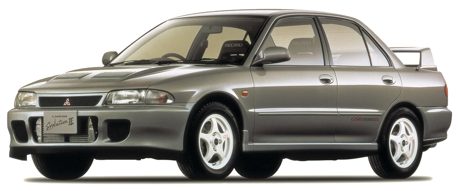
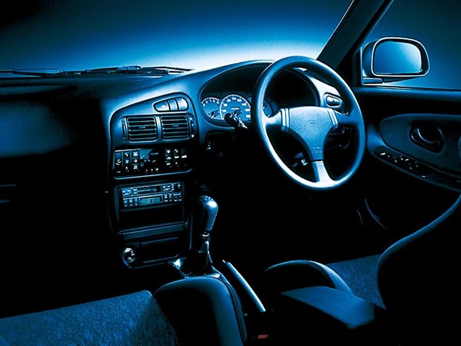
Mitsubishi Colt Mark V (CJ)/ Lancer Mark VI-VIII (CJ, CK, CL, CM, CN, CP) / Mirage Mark V (CJO) с бензиновыми двигателями: 4G13 SOHC 8V 1.3 л (1298 см³) 66-70-79 л.с./49-51-58 кВт, 4G13 SOHC 12V 1.3 л (1299 см³) 75 л.с./55 кВт, 4G15 SOHC/DOHC 1.5 л (1468 см³) 91-92-110 л.с./67-68-81 кВт, 4G18 SOHC 8V 1.6 л (1584 см³) 75 л.с./55 кВт, 4G92 SOHC 8V/16V 1.6 л (1597 см³) 90-112 л.с./66-83 кВт, 4G93 SOHC/DOHC 8V/16V/Turbo 1.8 л (1834 см³) 115-136-140-205 л.с./85-100-103-151 кВт и дизельными 4D68 2.0 л (1998 см³) 68-88 л.с./50-65 кВт; Руководство по эксплуатации, техническому обслуживанию и ремонту, особенности конструкции. Технические характеристики, электросхемы, контрольные размеры кузова, устройство, диагностика. Практическое пособие легковой автомобиль малого класса Мицубиси Мираж, Кольт, Лансер 7 с кузовами трехдверный хэтчбек, седан и универсал передне- и полноприводные модели пятого поколения выпуска с 1995 по 2003 год
ЕСЛИ ВЫ ВИДИТЕ ОШИБКУ 406 Not Acceptable и не видите документ, то скорей всего у Вас IP РФ и его надо сменить, на любой другой страны, с помощью VPN ( Scribd и SlideShare блокируют посетителей с Российским IP).
Mitsubishi Colt/ Lancer/ Mirage видео замена ремня генератора/ steering, alternator, timing belt и ТО/ spark plugs (Мицубиси Мираж, Кольт, Лансер 95-03)
Mitsubishi Colt V / Lancer VI-VIII / Mirage Mark V общая информация (Мицубиси Мираж, Кольт, Лансер 1995-2003)
Компания Mitsubishi традиционно начинает свой экспортный модельный ряде компактного переднеприводного хэтчбека Colt (Mirage — для японского рынка). Второе его поколение увидело свет в октябре 1983 года. По моде тех лет дизайн кузовов был с острыми углами. Вообще каждая новая генерация Colt/Lancer (а менялись они с регулярностью раз в четыре года) точно соответствовала моде своего времени что обычно давало положительный эффект при появлении новинки, но мгновенно делало устаревшей предыдущую модель. Для японского рынка где автомобили меняют регулярно, такой подход может быть, и оправдан.
Следующее с более солидной внешностью, поколение Colt/Mirage (С50) появилось в октябре 1987 года. Универсал сохранили старой модели. В январе 1988 года подоспел новый Lancer (в США его производили под маркой Eagle Summit). Только в 1989 году появился пятидверный хэтчбек Lancer. Трехдверные кузова хетчбэков этой серии неудобны для входа-выхода сидящих сзади пассажиров, так как двери недостаточно широки и открываются на небольшой угол. Зато при откинутом заднем сиденье вместимость багажника увеличивается до 1050 л, но погрузке мешают большие задние фонари. Багажник Lancer гораздо скромнее — всего 337 л. Салон без острых углов в интерьере достаточно просторен, в нем с удобством могут разместиться даже высокорослые люди. Рулевая колонка регулируемая, но гидроусилителя нет, а рулевое колесо может показаться слишком скользким. Сиденья спортивного типа удобные, но жесткие и с низкими спинками. Обзор с места водителя вполне удовлетворительный только боковые зеркала с электроприводом маловаты по площади. Шум от набегающего воздушного потока не раздражает. Управляемость даже «пожилого» Colt / Lancer весьма неплохая: устойчивость в поворотах и стабильный выбег по прямой. Подвеска достаточно комфортабельна (с полной нагрузкой) даже на неровной дороге. Гамма двигателей серии С50 осталась прежней, а мощность «турбированного» двигателя подняли до 145 л.с.
Осенью 1991 года появилось четвертое поколение Colt/Mirage (САО) с «миловидной мордочкой» и скругленными очертаниями кузова. Модель Lancer с трехобъемным кузовом седан в двухдверном (для США) и четырех дверном вариантах появилась летом 1992 года вместе с новым универсалом под названием Libero. Потребительские качества предшественников были бережно сохранены. У кузова с отличным качеством сборки и подгонки всех панелей достаточная жесткость и хорошая коррозионная стойкость да и ремонт его не так уж сложен.
Новая аккуратная панель приборов с хорошо различимыми приборами приятна и на вид, и на ощупь. Все материалы отделки отличного качества и смотрятся весьма пристойно, даже на подержанных экземплярах. Рулевая колонка (наконец, с гидроусилителем) регулируется по высоте. Водительское сиденье позволяет удобно расположиться и рослому водителю. Обзор отличный, под рукой есть все нужные регулировки (электро стеклоподъемников боковых зеркал и прерывистого режима работы «дворников»). В трехдверном хетчбэке заднее сиденье осталось таким же тесным, а доступ к нему — неудобным. И только при сложенном заднем сиденье багажник увеличивается до 1070 л. Заднее сиденье Lancer тоже не слишком просторно, но таковы уж принятые в классе данной размерности (сегмент С) стандарты. Зато универсал Libero более практичен особенно в полноприводном варианте.
Жесткость подвески к сожалению, возросла, а под нагрузкой и на плохой дороге Lancer может «вилять хвостом». На европейский рынок шли модели с 12-клапанным 75-сильным 1.3 литровым и 16-клапанными 1.6 и 1.8-литровыми двигателями. Двигатель с 12-клапанной головкой все же слабоват на низких оборотах и обеспечивает «подхват» только после 3000 об/мин. Самым популярным стал 1.6-литровый 113-сильный 4G92, который к тому же считается самым надежным (редкие поломки только по вине владельца). У механической 5-ступенчатой КП небольшие ходы и четкая фиксация. Выбор японских вариантов широк от того же 75-сильного до экзотических на таком компактном автомобиле 2.0 литровых 260-сильных турбодвигателей, которые агрегатируют и с полноприводной трансмиссией (Lancer GSR Evolution). Вот такие модели лучше не покупать, тем более подержанные так как в случае поломки их просто невозможно будет отремонтировать. Зато дизели и турбодизели (68 и 88 л.с.) гораздо практичнее.
Шестое по счету поколение Colt/Lancer/Mirage (CJO) появилось осенью 1995 года. Универсал Libero остался прежним. Все основные типы кузовов сохранились неизменными в очередной раз поменялся только стайлинг. В остальном это все тот же хорошо знакомый Colt/Lancer Бесшумен, удобен комфортен.
Гамма двигателей поменялась незначительно. На полноприводной спортивной версии Lancer Evolution V мощность 2.0 литрового «турбированного» двигателя поднялась уже до 280 л.с. (пожалуй кроме профессиональных раллистов, с такой машиной никто и не справится). В 1997 году появилась автоматическая трансмиссий нового поколения INVECS. Не электронным управлением КП позволяющим подстраиваться под конкретный стиль вождения и переключать передачи либо плавно в «экономичном» режиме, либо ускоренно в стиле «спорт». Прочие же особенности конструкции унаследованы от прежней пятой (CAO-тип)Colt/Lancer/Mirage.
В 1999 году был проведен косметический рестайлинг модели выпускаемой для Европы: увеличены передний воздухозаборник и фирменная эмблема изменены бамперы и приборная панель. На некоторых рынках продают полноприводные модификации с вискомуфтой в качестве межосевого дифференциала. Помимо хетчбэков, в США выпускают модификацию Mirage Coupe. Colt демонстрирует отличную управляемость, благодаря полностью независимой подвеске (впереди McPherson, сзади продольные и поперечные рычаги). Версии для СНГ адаптированы к местным условиям подвеска более «жесткая». Для разных рынков предусмотрены разные двигатели в Европе предлагают 1.3-литровый, мощностью 82 л.с. и новый 1.6-литровый, мощностью 116 л.с., на американские купе устанавливают 1.5-литровый (92 л.с.) или 1.8 литровый предыдущего поколения (111 л.с.).
В 2000 году в Японии ас 2001 в США и Европе дебютировали новые седаны Lancer шестого поколения. На внутреннем рынке модель называется Cedia. Формально автомобиль относится к классу С, однако благодаря увеличенной на 100 мм колесной базе и удлиненному на 190 мм кузову Lancer вплотную приближается по размерам к среднему классу D. Многорычажная подвеска сзади значительно улучшила плавность хода. Внешне Lancer более строг и консервативен чем модель предыдущего поколения, благодаря высокой решетке радиатора и большим трапецеидальным блок-фарам. Салон дорогих версии отделан пластиком «под алюминий». Полноприводные модификации оснащены центральной вискомуфтой с частичной блокировкой.
В начале 2001 года начались продажи универсала Wagon, который отличают элегантные вытянутые вдоль задних стоек стоп-сигналы. На новый Lancer устанавливают двигатель 1.5 л 101 л.с., или 1.8 л 130 л.с., агрегатируемые на выбор с 5-ступенчатой «механикой» либо с вариатором CVT. В Штатах седан оснащают только двигателем 2.0 л — 120 л.с., и по заказу автоматической секвентальной трансмиссией. Вершина модельного ряда Lancer — гражданская версия боевого Evo VII, участвующего в чемпионате мира по ралли с аэродинамическим кузовом и большим задним антикрылом. Двух литровый двигатель с промежуточным охладителем воздуха и турбонаддувом Garrett развивает 280 л.с. В некоторых странах Юго-Восточной Азии продолжается выпуск модели Lancer предыдущего поколения с двигателями 1.6 л — 113 л.с. и 1.8 л — 122 л.с. В Японии, Австралии и Океании продается универсал Lancer Wagon образца 1992 года с 1,8-литровым мотором. Для внутреннего рынка выпускают грузопассажирский двухместный универсал фургон Libero, на базе Lancer четвертого поколения с багажным отделением полезным объемом 2440 л. Двигатель на Libero 1.5 литровый мощностью 91 л с или 1.9-литровый турбодизель в 88 л.с., коробка передач механическая 5-ступенчатая.
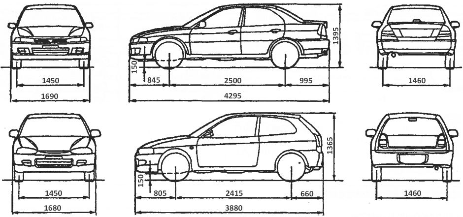
| № | Спецификация / Specs | Данные |
| Габариты (мм/mm) и масса (кг/kg) / Dimensions and Weight | ||
| 1 | Длина / Length | 4295 |
| 2 | Ширина (без/с зеркалами) / Width | 1690 |
| 3 | Высота (загружен/пустой) / Height | 1395 |
| 4 | Колёсная база / Wheelbase | 2500 |
| 5 | Дорожный просвет (клиренс) / Ground clearance | 150 |
| 6 | Снаряжённая масса / Total (curb) weight | 995-1090 |
| Полная масса / Gross (max.) weight | 1505 | |
|
Двигатель / Engine |
||
| 7 | Тип / Engine Type, Code | Бензиновый, жидкостного охлаждения, четырехтактный, 4G92 |
| 8 | Количество цилиндров / Cylinder arrangement: Total number of cylinders, of valves | 4-цилиндровый, рядный, 8V, SOHC с верхним расположением одного распределительного вала |
| 9 | Диаметр цилиндра / Bore | 81.0 мм |
| 10 | Ход поршня / Stroke | 77.5 мм |
| 11 | Объём / Engine displacement | 1597 см³ |
| 12 | Система питания / Fuel supply, Aspiration | Распределенный впрыск топлива MPI |
| Атмосферный | ||
| 13 | Степень сжатия / Compression ratio | 10.0:1 |
| 14 | Максимальная мощность / Max. output power kW (HP) at rpm | 66 кВт (90 л.с.) при 5500 об/мин |
| 15 | Максимальный крутящий момент / Max. torque N·m at rpm | 135 Нм при 4000 об/мин |
|
Трансмиссия / Transmission |
||
| 16 | Сцепление / Clutch type | Однодисковое, сухое, с диафрагменной нажимной пружиной и гасителем крутильных колебаний, постоянно замкнутого типа |
| 17 | КПП / Transmission type | F5M41 МКПП 5 пятиступенчатая механическая, двухвальная, с синхронизаторами на всех передачах переднего хода |
О Книге
- Название: Mitsubishi Colt, Lancer руководство по эксплуатации, техническому обслуживанию, ремонт, особенности конструкции
- Бензиновые двигатели: 4G13 SOHC 8V 1.3 л (1298 см³) 66-70-79 л.с./49-51-58 кВт, 4G13 SOHC 12V 1.3 л (1299 см³) 75 л.с./55 кВт, 4G15 1.5 л (1468 см³) 91-92-110 л.с./67-68-81 кВт, 4G18 1.6 л (1584 см³) 75 л.с./55 кВт, 4G92 1.6 л (1597 см³) 90-112 л.с./66-83 кВт, 4G93 1.8 л (1834 см³) 115-136-140-205 л.с./85-100-103-151 кВт и дизельными 4D68 2.0 л (1998 см³) 68-88 л.с./50-65 кВт
- Выпуск с 1995 года
- Серия: «Автолюбитель»
- Год издания: 2003
- Автор: Коллектив авторов
- Издательство: «Ассоциация независимых издателей»
- Формат: PDF
- Страниц в книге: 279
- Размер: 193.11 МБ
- Язык: Русский
- Количество электросхем: 37
Руководства по ремонту и обслуживанию старых автомобилей Mitsubishi Motors (~ до 2002 г.в.).
| ↑ На главную страницу
|
Содержание
- 1 Mitsubishi 3000GT
- 2 Mitsubishi Carisma
- 3 Mitsubishi Dion
- 4 Mitsubishi Colt / Mirage / Lancer
- 5 Mitsubishi Eclipse / Talon / Laser
- 6 Mitsubishi FTO
- 7 Mitsubishi Galant
- 8 Mitsubishi L300 / L400 / Delica / SpaceGear
- 9 Mitsubishi Lancer Evolution
- 10 Mitsubishi Pajero / Montero
- 11 Mitsubishi Sigma
- 12 Mitsubishi RVR / Space Runner / Space Wagon
- 13 Mitsubishi Space Star
- 14 Пассажирские автомобили и лёгкий коммерческий транспорт Mitsubishi
Mitsubishi 3000GT
- Mitsubishi 3000GT 1991 Service Manual, vol. 1 (Engine, Chassis, Body), eng., pdf, 76,6 МБ
- Mitsubishi 3000GT 1991 Service Manual, vol. 2 (Electrical), eng., pdf, 22,4 МБ
- Mitsubishi 3000GT 1992-1996 Service Manual, vol. 1 (Engine, Chassis, Body), eng., pdf, 63,1 МБ
- Mitsubishi 3000GT 1992-1996 Service Manual, vol. 2 (Electrical), eng., pdf, 40,3 МБ
- Mitsubishi 3000GT 1993 Technical Information Manual, eng., pdf, 12,5 МБ
- Mitsubishi 3000GT 1991-1996 Manual Transmission Service Manual, eng., pdf, 2,96 МБ
- Mitsubishi 3000GT 1997 Wiring Diagrams, eng., pdf в архиве zip, 0,97 МБ
- Mitsubishi 3000GT 1991-1993 ECU Pin-Outs, eng., xls в архиве zip, 11,7 кБ
- Mitsubishi 3000GT 1993 Body Repair Manual, eng., pdf в архиве zip, 33,6 МБ
- Mitsubishi 3000GT & Spyder 1995 Service Manual Supplement, eng., pdf, 4,56 МБ
Mitsubishi Carisma
- Mitsubishi Carisma 1996-2002 Workshop Manuals, рус., eng., pdf в архиве zip, 179 МБ
- Mitsubishi Carisma 1996-2000 Workshop Manual, eng., pdf в архиве zip, 164 МБ
- Mitsubishi Carisma 1996-2003 Electrical Wiring, eng., pdf в архиве zip, 42,9 МБ
- Mitsubishi Carisma 1996-1997 Body Repair Manual, eng., pdf в архиве zip, 7,18 МБ
- Автолитература по автомобилю Mitsubishi Carisma в Легион-Автодата
Mitsubishi Dion
- Mitsubishi Dion 2000 Workshop Manuals, jp., pdf в архиве zip, 248 МБ
Mitsubishi Colt / Mirage / Lancer
- Mitsubishi Colt/Lancer 1994-1998 Workshop Manual, eng., pdf в архиве zip, 41,2 МБ
- Mitsubishi Colt/Lancer 1996 Workshop Manual, eng., pdf в архиве zip, 21,5 МБ
- Mitsubishi Colt/Lancer 1998-2001 Workshop Manual Supplement, eng., pdf в архиве zip, 5,04 МБ
- Mitsubishi Colt/Lancer 1996-2001 Workshop Manual, eng., pdf в архиве zip, 28,3 МБ
- Mitsubishi Colt/Lancer 1996-2001 Workshop Manuals, eng., pdf в архиве zip, 42,0 МБ
- Mitsubishi Colt/Lancer 1996-2001 Workshop Manuals, рус., pdf в архиве zip, 21,0 МБ
- Mitsubishi Colt/Lancer 1996-1999 (CE, CG) Workshop Manual, eng., pdf в архиве zip, 59,1 МБ
- Mitsubishi Colt/Lancer 1992 MY (CA, CB, CC, CD) Electrical Wiring, eng., pdf в архиве zip, 23,6 МБ
- Mitsubishi Colt/Lancer 1996 MY (CJ, CK) Electrical Wiring, eng., pdf в архиве zip, 15,6 МБ
- Mitsubishi Colt/Lancer 1996 Body Repair Manual, eng., pdf в архиве zip, 6,02 МБ
- Mitsubishi Colt 1992 Body Repair Manual, eng., pdf в архиве zip, 24,1 МБ
- Mitsubishi Mirage Service Manual, eng., pdf в архиве zip, 93,1 МБ
- Mitsubishi Mirage Wiring Diagrams, eng., pdf в архиве zip, 572 кБ
- Автолитература по автомобилю Mitsubishi Colt/Lancer в Легион-Автодата
- Автолитература по автомобилю Mitsubishi Lancer в Легион-Автодата
Mitsubishi Eclipse / Talon / Laser
- Mitsubishi Eclipse / Eclipse Spyder 1990-1998 Service Manual and Electrical Wiring, eng., pdf в архиве zip, 81,6 МБ
- Mitsubishi Eclipse 1990-1994 Service Manuals, eng., pdf в архиве zip, 102 МБ
- Mitsubishi Eclipse 1996-1999 Workshop Manuals, eng., pdf в архиве zip, 168 МБ
- Mitsubishi Eclipse 2000-2002 Service Manual (include Wiring Diagrams), eng., pdf в архиве zip, 112 МБ
- Mitsubishi Eclipse 1990-1994 Electrical Wiring, eng., pdf в архиве zip, 14,3 МБ
- Mitsubishi Eclipse 1996-1999 Electrical Wiring, eng., pdf в архиве zip, 32,2 МБ
- Mitsubishi Eclipse 1991 Body Repair Manual, eng., pdf в архиве zip, 29,6 МБ
- Mitsubishi Eclipse 1996 Body Repair Manual, eng., pdf в архиве zip, 59,9 МБ
Mitsubishi FTO
- Mitsubishi FTO 1998 Handbook, eng., pdf, 6,02 МБ
- Mitsubishi FTO 1998 Workshop Manuals, eng., pdf в архиве zip, 133 МБ
- Mitsubishi FTO 1998 Electrical Wiring, eng., pdf, 23,1 МБ
Mitsubishi Galant
- Mitsubishi Galant 1989-1993 Service Manual.zip, eng., pdf в архиве zip, 59,7 МБ
- Mitsubishi Galant 1989-1993 Electrical Wiring, eng., pdf в архиве zip, 16,1 МБ
- Mitsubishi Galant 1996-1996 Workshop Manual, eng., pdf в архиве zip, 45,2 МБ
- Mitsubishi Galant 1993-1996 Electrical Wiring, eng., pdf в архиве zip, 55,1 МБ
- Mitsubishi Galant 1993 Body Repair Manual, eng., pdf в архиве zip, 25,8 МБ
- Mitsubishi Galant 1997 User Manual, рус., pdf в архиве zip, 12,1 МБ
- Mitsubishi Galant 1997-2001 Workshop Manuals, eng., pdf в архиве zip, 222 МБ
- Mitsubishi Galant 1997-2001 Workshop Manuals, рус., pdf в архиве zip, 23,6 МБ
- Mitsubishi Galant 1997-2001 Electrical Wiring, eng., pdf в архиве zip, 49,5 МБ
- Mitsubishi Galant 1997 Body Repair Manual, eng., pdf в архиве zip, 7,04 МБ
- Автолитература по автомобилю Mitsubishi Galant в Легион-Автодата
Mitsubishi L300 / L400 / Delica / SpaceGear
- Mitsubishi L300 Workshop Manual (частично), eng., pdf в архиве zip, 3,60 МБ
- Mitsubishi L400 1995-1998 Workshop Manuals, eng., pdf в архиве zip, 66,2 МБ
- Mitsubishi L400 1995-1999 Electrical Wiring, eng., pdf в архиве zip, 27,6 МБ
- Mitsubishi Delica SpaceGear 1997 User Manual, eng., pdf, 2,75 МБ
- Автолитература по автомобилю Mitsubishi L300 в Легион-Автодата
- Автолитература по автомобилю Mitsubishi L400 в Легион-Автодата
- Автолитература по автомобилю Mitsubishi Delica в Легион-Автодата
- Автолитература по автомобилю Mitsubishi SpaceGear в Легион-Автодата
Mitsubishi Lancer Evolution
- Mitsubishi Lancer Evolution IV, V, VI, VII Workshop Manuals, eng., pdf в архиве zip, 89,6 МБ
- Mitsubishi Lancer Evo IV, V, VI Conversion to Evo VII, VIII ECU Pinout Diagrams, eng., xls в архиве zip, 326 кБ
- Mitsubishi Lancer Evolution IV, V 1998 Workshop Manual, eng., pdf в архиве zip, 10,3 МБ
- Mitsubishi Lancer Evolution IV, V 1998 Technical Infomation Manual, eng., pdf в архиве zip, 2,07 МБ
- Mitsubishi Lancer Evolution IV, V 1998 Wiring Diagrams, eng., pdf в архиве zip, 4,23 МБ
- Mitsubishi Lancer Evolution VI 1999 Workshop Manual Supplement, eng., pdf в архиве zip, 9,64 МБ
- Mitsubishi Lancer Evolution VI 1999 Technical Infomation Manual, eng., pdf в архиве zip, 708 кБ
- Mitsubishi Lancer Evolution VI Wiring Diagrams, eng., pdf в архиве zip, 6,58 МБ
- Mitsubishi Lancer Evolution VII 2001 Service Manual, eng., pdf в архиве zip, 56,6 МБ
- Mitsubishi Lancer Evolution VII Wiring Diagrams, eng., pdf в архиве zip, 21,7 МБ
- Mitsubishi Lancer Evolution VIII 2003 Service Manual, eng., pdf в архиве zip, 10,8 МБ
- Mitsubishi Lancer Evolution VIII 2003 Workshop Manual, eng., pdf в архиве zip, 136 МБ
- Mitsubishi Lancer Evolution VIII MR 2004 Workshop Manual Supplement, eng., pdf в архиве zip, 15,0 МБ
- Mitsubishi Lancer Evolution VIII MR Wiring Diagrams, eng., pdf в архиве zip, 16,9 МБ
- Mitsubishi Lancer Evolution VIII USDM Wiring Diagrams, eng., pdf в архиве zip, 9,49 МБ
Mitsubishi Pajero / Montero
- Руководство пользователя Mitsubishi Pajero II, eng., pdf, 47,0 МБ
- Mitsubishi Pajero 1984-1991 Worshop Manuals & Electrical Wiring, eng., pdf в архиве zip, 365 МБ
- Mitsubishi Pajero II 1991-1998 Worshop Manuals, рус., eng., pdf в архиве zip, 285 МБ
- Mitsubishi Pickup 1991 Electrical Wiring, eng., pdf в архиве zip, 371 кБ
- Mitsubishi Pajero II 1991-1999 Electrical Wiring, eng., pdf в архиве zip, 49,5 МБ
- Mitsubishi Pajero II 1998 Body Repair Manual, eng., pdf в архиве zip, 18,6 МБ
- Mitsubishi Montero 1983 Service Manual, eng., pdf, 148 МБ
- Mitsubishi Montero 1984 Service Manual, eng., pdf, 113 МБ
- Mitsubishi Montero 1987 Service Manual, vol. 1 (Engine, Chassis, Body), eng., pdf, 164 МБ
- Mitsubishi Montero 1987 Service Manual, vol. 2 (Electrical), eng., pdf, 53,4 МБ
- Mitsubishi Montero 1989 Service Manual, vol. 1 (Engine, Chassis, Body), eng., pdf в архиве zip, 41,6 МБ
- Mitsubishi Montero 1989 Service Manual, vol. 2 (Electrical), eng., pdf в архиве zip, 11,8 МБ
- Mitsubishi Montero 1992 Service Manual, vol. 1 (Engine, Chassis, Body), eng., pdf, 129 МБ
- Mitsubishi Montero 1992 Service Manual, vol. 2 (Electrical), eng., pdf, 56,1 МБ
- Mitsubishi Montero 1992-1995 Service Manual, vol. 1 (Engine, Chassis, Body), eng., pdf, 72,7 МБ
- Mitsubishi Montero 1992-1995 Service Manual, vol. 2 (Electrical), eng., pdf, 20,9 МБ
- Mitsubishi Montero 1996 Service Manual, vol. 1 (Engine, Chassis, Body), eng., pdf, 233 МБ
- Mitsubishi Montero 1996 Service Manual, vol. 2 (Electrical), eng., pdf, 59,8 МБ
- Mitsubishi Montero 1998 Service Manual, vol. 1 (Engine, Transmission, Fuel), eng., pdf, 166 МБ
- Mitsubishi Montero 1998 Service Manual, vol. 2 (Body, Axles, Electrical), eng., pdf, 179 МБ
- Mitsubishi Montero 1988-1996 Technical Service Bulletins, eng., pdf в архиве zip, 13,7 МБ
- Автолитература по автомобилю Mitsubishi Pajero в Легион-Автодата
- Автолитература по автомобилю Mitsubishi Montero в Легион-Автодата
- Книга по ремонту Mitsubishi Pajero II дизель в формате PDF в Легион-Автодата
Mitsubishi Sigma
- Mitsubishi Sigma 1991-1995 Workshop Manuals, eng., pdf в архиве zip, 52,9 МБ
- Mitsubishi Sigma 1991-1995 Electrical Wiring, eng., pdf в архиве zip, 52,2 МБ
- Mitsubishi Sigma 1997 Workshop Manual, eng., pdf в архиве zip, 28,3 МБ
- Mitsubishi Sigma 1997 Electrical Wiring, eng., pdf в архиве zip, 6,63 МБ
- Автолитература по автомобилю Mitsubishi Sigma в Легион-Автодата
Mitsubishi RVR / Space Runner / Space Wagon
- Mitsubishi Space Runner / Space Wagon 1992-1997 Workshop Manual, eng., pdf в архиве zip, 59,0 МБ
- Mitsubishi Space Runner / Space Wagon 1999-2001 Workshop Manuals, eng., pdf в архиве zip, 76,8 МБ
- Mitsubishi Space Runner / Space Wagon 1992-1997 Electrical Wiring, eng., pdf в архиве zip, 25,0 МБ
- Mitsubishi Space Runner / Space Wagon 1999-2001 Electrical Wiring, eng., pdf в архиве zip, 25,9 МБ
- Mitsubishi Space Runner / Space Wagon 1999 Body Repair Manual, eng., pdf в архиве zip, 7,90 МБ
- Автолитература по автомобилю Mitsubishi RVR в Легион-Автодата
- Автолитература по автомобилю Mitsubishi Space Runner в Легион-Автодата
- Автолитература по автомобилю Mitsubishi Space Wagon в Легион-Автодата
Mitsubishi Space Star
- Mitsubishi Space Star 1999-2003 Workshop Manuals, eng., pdf в архиве zip, 64,7 МБ
- Mitsubishi Space Star 1999-2003 Electrical Wiring, eng., pdf в архиве zip, 20,8 МБ
- Mitsubishi Space Star 1998 Body Repair Manual, eng., pdf в архиве zip, 7,26 МБ
- Автолитература по автомобилю Mitsubishi Space Star в Легион-Автодата
Пассажирские автомобили и лёгкий коммерческий транспорт Mitsubishi
- Passenger Cars and Light Commercial Vehicles Body Repair Manuals and Paint Condition Manual, eng., pdf в архиве zip, 10,7 МБ
- Сервисные бюллетени Mitsubishi Motors Australia, 2003 г., eng., pdf в архиве zip, 6,98 МБ
- Автолитература по автомобилю Mitsubishi Fuso Fighter в Легион-Автодата
- Автолитература по автомобилю Mitsubishi Fuso Super Great в Легион-Автодата
Руководство на английском языке по кузовному ремонту автомобилей Mitsubishi Lancer/Lancer Station Wagon 1993 года выпуска.
- Автор: —
- Издательство: Mitsubishi Motors Corp.
- Год издания: 1992
- Страниц: —
- Формат: PDF
- Размер: 25,2 Mb
- Автор: —
- Издательство: Mitsubishi Motors Corp.
- Год издания: 1993-2000
- Страниц: —
- Формат: PDF
- Размер: 33,9 Mb
Сборник схем на английском языке электрооборудования автомобиля Mitsubishi Lancer 1997-2000 годов выпуска.
- Автор: —
- Издательство: Mitsubishi Motors Corp.
- Год издания: 1996-1999
- Страниц: —
- Формат: PDF
- Размер: 5,3 Mb
Сборник схем на английском языке электрооборудования автомобиля Mitsubishi Lancer 2007 года выпуска.
- Автор: —
- Издательство: Mitsubishi Motors Corp.
- Год издания: —
- Страниц: —
- Формат: PDF
- Размер: 99,3 Mb
Мультимедийное руководство на английском языке по техническому обслуживанию и ремонту автомобилей Mitsubishi Lancer/Lancer SportBack/Lancer Evolution 2004 года выпуска.
- Автор: —
- Издательство: Mitsubishi Motors
- Год издания: 2003
- Страниц: —
- Формат: —
- Размер: 191,5 Mb
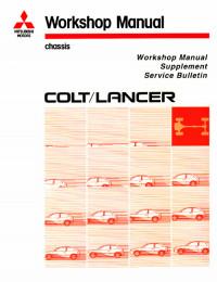
Сборник руководств на английском языке по техническому обслуживанию и ремонту автомобилей Mitsubishi Colt и Mitsubishi Lancer 1992-1996 годов выпуска.
- Автор: —
- Издательство: Mitsubishi Motors Corp.
- Год издания: —
- Страниц: —
- Формат: PDF
- Размер: 41,2 Mb
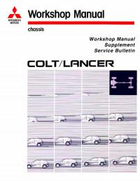
Сборник руководств на английском языке по техническому обслуживанию и ремонту автомобилей Mitsubishi Colt и Mitsubishi Lancer 1996-2001 годов выпуска.
- Автор: —
- Издательство: Mitsubishi Motors Corp.
- Год издания: 1995-2000
- Страниц: —
- Формат: PDF
- Размер: 26,5 Mb
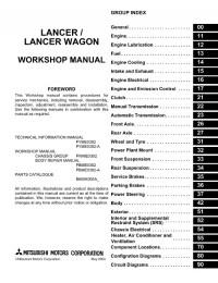
Руководство на английском языке по техническому обслуживанию и ремонту автомобилей Mitsubishi Lancer/Lancer Wagon 2005 года выпуска. .
- Автор: —
- Издательство: Mitsubishi Motors Corp.
- Год издания: 2004
- Страниц: —
- Формат: PDF
- Размер: 46,3 Mb

Сборник руководств на английском языке по техническому обслуживанию и ремонту автомобиля Mitsubishi Lancer 2006 года выпуска.
- Автор: —
- Издательство: Mitsubishi Motors Corp.
- Год издания: —
- Страниц: —
- Формат: PDF
- Размер: 66,2 Mb
Сборник мультимедийных руководств на английском языке по техническому обслуживанию и ремонту автомобилей Mitsubishi Lancer/Lancer Sportback 2009-2011 годов выпуска
- Автор: —
- Издательство: Mitsubishi Motors
- Год издания: —
- Страниц: —
- Формат: —
- Размер: 4,0 Gb
уководство на английском языке по техническому обслуживанию и ремонту автомобиля Mitsubishi Lancer 2012 года выпуска.
- Автор: —
- Издательство: Mitsubishi Motors Corp.
- Год издания: —
- Страниц: 1253
- Формат: PDF
- Размер: 40,6 Mb
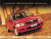
Руководство на английском языке по техническому обслуживанию и ремонту автомобиля Mitsubishi Lancer серий CE/CG. .
- Автор: —
- Издательство: Mitsubishi Motors Corp.
- Год издания: 2001-2002
- Страниц: —
- Формат: PDF
- Размер: 61,5 Mb

Руководство на английском и испанском языках по техническому обслуживанию и ремонту (включая руководство по кузовному ремонту) автомобиля Mitsubishi Lancer 2004 года выпуска.
- Автор: —
- Издательство: Mitsubishi Motors Corp.
- Год издания: 2003
- Страниц: —
- Формат: PDF
- Размер: 418,6 Mb
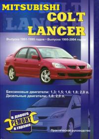
Руководство по ремонту автомобилей Mitsubishi Colt и Mitsubishi Lancer 1991-1995 годов выпуска с бензиновыми и дизельными двигателями.
- Автор: —
- Издательство: СверчокЪ
- Год издания: 2005
- Страниц: 279
- Формат: PDF
- Размер: 38,2 Mb
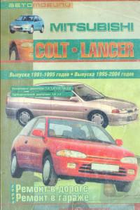
Руководство по ремонту автомобилей Mitsubishi Colt и Mitsubishi Lancer 1991-2004 годов выпуска с бензиновыми и дизельными двигателями
- Автор: В. Покрышкин
- Издательство: СверчокЪ
- Год издания: 2005
- Страниц: 279
- Формат: DjVu
- Размер: 19,9 Mb
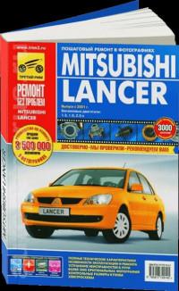
Руководство по эксплуатации, техническому обслуживанию и ремонту автомобиля Mitsubishi Lancer с 2001 года выпуска с бензиновыми двигателями объемом 1,3/1,6/2,0 л.
- Автор: —
- Издательство: Третий Рим
- Год издания: —
- Страниц: 304
- Формат: —
- Размер: —
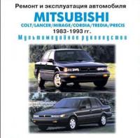
Мультимедийное руководство по эксплуатации и ремонту автомобилей Mitsubishi Colt/Lancer/Mirage/Cordia/Tredia/Precis 1983-1993 годов выпуска.
- Автор: —
- Издательство: —
- Год издания: —
- Страниц: —
- Формат: ISO
- Размер: 196,8 Mb

Сборник руководств по техническому обслуживанию и ремонту автомобиля Mitsubishi Lancer 2008 года выпуска.
- Автор: —
- Издательство: Mitsubishi Motors Corp.
- Год издания: 2007
- Страниц: —
- Формат: PDF
- Размер: 186,7 Mb
Сборник руководств по техническому обслуживанию и ремонту автомобилей Mitsubishi Colt и Mitsubishi Lancer 1996-2001 годов выпуска.
- Автор: —
- Издательство: Mitsubishi Motors Corp.
- Год издания: 1995-2000
- Страниц: —
- Формат: PDF
- Размер: 54,0 Mb
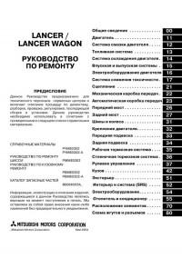
Руководство по техническому обслуживанию и ремонту автомобилей Mitsubishi Lancer/Lancer Wagon 2005 года выпуска.
- Автор: —
- Издательство: Mitsubishi Motors Corp.
- Год издания: 2004
- Страниц: —
- Формат: PDF
- Размер: 159,7 Mb
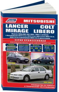
Руководство по эксплуатации, техническому обслуживанию и ремонту автомобилей Mitsubishi Colt/Lancer/Mirage 1991-1996 и Mitsubishi Libero 1992-2002 годов выпуска с бензиновыми и дизельными двигателями.
- Автор: —
- Издательство: Легион-Автодата
- Год издания: —
- Страниц: 448
- Формат: —
- Размер: —
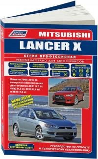
Руководство по эксплуатации, техническому обслуживанию и ремонту автомобиля Mitsubishi Lancer X 2006-2016 годов выпуска с бензиновыми двигателями.
- Автор: —
- Издательство: Легион-Автодата
- Год издания: —
- Страниц: 500
- Формат: —
- Размер: —
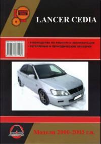
Руководство по эксплуатации и ремонту автомобиля Mitsubishi Lancer Cedia 2000-2003 года выпуска.
- Автор: —
- Издательство: Монолит
- Год издания: —
- Страниц: 567
- Формат: PDF
- Размер: 47,0 Mb
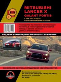
уководство по эксплуатации и ремонту автомобилей Mitsubishi Lancer X и Mitsubishi Galant Fortis с 2006 года выпуска с бензиновыми и дизельными двигателями.
- Автор: —
- Издательство: Монолит
- Год издания: —
- Страниц: 384
- Формат: —
- Размер: —

Руководство по эксплуатации и ремонту автомобилей Mitsubishi Colt и Mitsubishi Lancer/Lancer Wagon с 1992 года выпуска с бензиновыми и дизельными двигателями.
- Автор: —
- Издательство: Монолит
- Год издания: —
- Страниц: 326
- Формат: —
- Размер: —
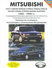
Руководство по эксплуатации, техническому обслуживанию и ремонту автомобилей Mitsubishi Colt/Lancer/Mirage/Cordia/Tredia/Precis/Galant/Sigma/Eterna/Magna/Sapporo 1983-1993 годов выпуска с бензиновыми и дизельными двигателями.
- Автор: —
- Издательство: Техно-BOOK
- Год издания: 2005
- Страниц: 273
- Формат: PDF
- Размер: 34,7 Mb
Руководство по эксплуатации и техническому обслуживанию автомобиля Mitsubishi Lancer 2008 года выпуска.
- Автор: —
- Издательство: Mitsubishi Motors Corp.
- Год издания: 2007
- Страниц: 487
- Формат: PDF
- Размер: 48,9 Mb

Руководство по эксплуатации и техническому обслуживанию автомобиля Mitsubishi Lancer с 2003 года выпуска.
- Автор: —
- Издательство: MoToR
- Год издания: —
- Страниц: 320
- Формат: —
- Размер: —
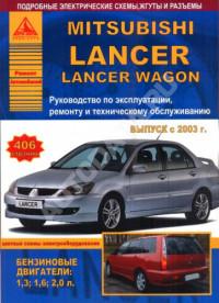
Руководство по эксплуатации, техническому обслуживанию и ремонту автомобилей Mitsubishi Lancer/Lancer Wagon с 2003 года выпуска с бензиновыми двигателями объемом 1,3/1,6/2,0 л
- Автор: —
- Издательство: Арго-Авто
- Год издания: —
- Страниц: 406
- Формат: —
- Размер: —

Руководство по эксплуатации, техническому обслуживанию и ремонту автомобиля Mitsubishi Lancer с 2007 года выпуска с бензиновыми двигателями объемом 1,5/1,8/2,0 л.
- Автор: —
- Издательство: Арго-Авто
- Год издания: —
- Страниц: 600
- Формат: —
- Размер: —
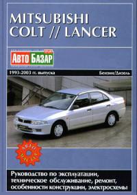
Руководство по эксплуатации, техническому обслуживанию и ремонту автомобилей Mitsubishi Colt и Mitsubishi Lancer 1993-2003 годов выпуска с бензиновыми и дизельными двигателями.
- Автор: —
- Издательство: Автомастер
- Год издания: 2003
- Страниц: 281
- Формат: PDF
- Размер: 16,4 Mb
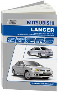
Руководство по эксплуатации, техническому обслуживанию и ремонту автомобиля Mitsubishi Lancer 2003-2010 годов выпуска с бензиновыми двигателями объемом 1,3/1,6 л.
- Автор: —
- Издательство: Автонавигатор
- Год издания: —
- Страниц: 304
- Формат: —
- Размер: —
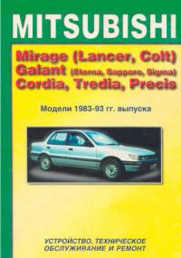
Руководство по техническому обслуживанию и ремонту автомобилей Mitsubishi Mirage/Lancer/Colt/Galant/Eterna/Sapporo/Sigma/Cordia/Tredia/Precis 1983-1993 годов выпуска.
- Автор: —
- Издательство: MoToR
- Год издания: 1996
- Страниц: 183
- Формат: —
- Размер: —
Руководство по техническому обслуживанию и ремонту автомобилей Mitsubishi Colt и Mitsubishi Lancer 1984-1992 годов выпуска.
- Автор: Г.Р. Этцольд
- Издательство: Arinas
- Год издания: 1994
- Страниц: 339
- Формат: DjVu
- Размер: 10,4 Mb
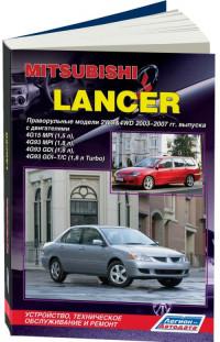
Руководство по техническому обслуживанию и ремонту автомобиля Mitsubishi Lancer с правым рулем 2003-2007 годов выпуска с бензиновыми двигателями объемом 1,5/1,8 л.
- Автор: —
- Издательство: Легион-Автодата
- Год издания: —
- Страниц: 544
- Формат: —
- Размер: —
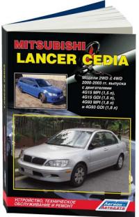
Руководство по техническому обслуживанию и ремонту автомобиля Mitsubishi Lancer Cedia 2000-2003 годов выпуска с бензиновыми двигателями объемом 1,5/1,8 л.
- Автор: —
- Издательство: Легион-Автодата
- Год издания: —
- Страниц: 584
- Формат: —
- Размер: —
-
Page 1
WORKSHOP MANUAL EVOLUTION-IV EVOLUTION-V Pub. No. S9806CNCP9… -
Page 2: Table Of Contents
General ……Engine ……Engine Lubrication .
-
Page 3
ELECTRICAL WIRING CONTENTS HOW TO READ THE WIRING DIAGRAMS ….. . ELECTRICAL WIRING (EVOLUTION-IV) ….. . . ELECTRICAL WIRING (EVOLUTION-V) . -
Page 4
NOTES… -
Page 5
ELECTRICAL WIRING (EVOLUTION-IV) CONTENTS WIRING HARNESS CONFIGURATION FOG LAMP ……DIAGRAMS ……ROOM LAMP AND LUGGAGE COMPARTMENT LAMP . -
Page 6: Wiring Harness Configuration Diagrams
WIRING HARNESS CONFIGURATION DIAGRAMS – Engine Compartment WIRING HARNESS CONFIGURATION DIAGRAMS ENGINE COMPARTMENT Ground cable Connector symbol –01 thru –50 A-01 (2-B) Brake fluid level switch A-20 (4-B) Windshield wiper motor A-03 (1-B) Noise condenser A-21 (8-B) Hydraulic unit <vehicles with ABS> A-04 (1) Alternator A-22 (2-B)
-
Page 7
WIRING HARNESS CONFIGURATION DIAGRAMS – Engine Compartment A-29 (2-B) Front harness and battery harness A-39 (1-B) Engine coolant temperature gauge unit combination A-45 (1) Horn (RH) A-33 (1) Horn (LH) A-46 (1) Horn (RH) A-34 (1) Horn (LH) A-49 (2-BR) Dual pressure switch A-35 (2-BR) Outside air temperature sensor <vehicles… -
Page 8
WIRING HARNESS CONFIGURATION DIAGRAMS – Engine Compartment Ground cable Connector symbol –51 thru –131 A-51 (3-B) Crank angle sensor A-80X (5) Horn relay <vehicles with SRS air bag> A-52 (1-B) Oil pressure switch A-82X (5) Radiator fan relay (LO) A-53 (2-B) Injector (No.1) A-84X (5) Headlamp relay… -
Page 9
WIRING HARNESS CONFIGURATION DIAGRAMS – Engine Compartment A-97 (3-B) Camshaft position sensor A-114X (4) Condenser fan relay (HI) A-99 (2-B) Condenser fan motor A-116X (4) A/C compressor relay A-101 (1) Power steering oil pressure switch A-117 (2-GR) Side turn signal lamp (RH) A-102 (1) Spare connector for fog lamp A-123 (5-B) -
Page 10: Dash Panel
WIRING HARNESS CONFIGURATION DIAGRAMS – Dash Panel DASH PANEL Connector symbol –01 thru –37 B-01 (2-R) Passenger seat air bag module (squib) B-07 (8) Blower switch B-02 (2) Heater water temperature sensor <vehicles with manual air conditioner> <vehicles with fully automatic air conditioner> B-08 (25) Meter and gauge B-03 (2-B)
-
Page 11
WIRING HARNESS CONFIGURATION DIAGRAMS – Dash Panel Interior relay box B-19 (22) Body harness and instrument panel harness B-33 (2) Blower motor combination <vehicles with fully automatic air conditioner> B-21 (2) Stop lamp switch (driver side) B-34 (4) Blower high speed relay <vehicles with fully B-22 (16-B) Diagnosis connector automatic air conditioner>… -
Page 12
WIRING HARNESS CONFIGURATION DIAGRAMS – Dash Panel Connector –38 symbol thru –65 –94 thru –97 B-38 (2) Sunlight sensor <vehicles with fully B-43 (6-B) Defogger switch <vehicles with heater or automatic air conditioner> manual air conditioner> B-39 (6) Air mix damper motor and potentiometer B-44 (6) Body harness and roof harness combina- <vehicles with fully automatic air condi-… -
Page 13
WIRING HARNESS CONFIGURATION DIAGRAMS – Dash Panel Interior relay box <Vehicles without interior relay box> B-52 (16-B) Control harness and body harness B-65 (16-B) Control harness and body harness combination <vehicles with ABS> combination B-59 (26-Y) Engine-ECU B-94 (13) Control harness and body harness B-60 (16-Y) Engine-ECU combination <vehicles with AYC>… -
Page 14
WIRING HARNESS B-10 CONFIGURATION DIAGRAMS – Dash Panel Connector <Junction block> symbol –66 <Front view> <Rear view> thru –89 –98 <Steering column> B-66 (2) Junction block and roof harness combination B-79 (12) Junction block and ETACS-ECU combination, B-67 (11) Junction block and front harness combination or junction block and ECU combination B-68 (3) Turn signal / hazard flasher unit… -
Page 15
B-11 NOTES… -
Page 16: Floor, Roof, And Seat
WIRING HARNESS B-12 CONFIGURATION DIAGRAMS – Floor, Roof, and Seat FLOOR, ROOF, AND SEAT Connector symbol D-01 (20) Receiver D-09 (1) Map lamp <vehicles with keyless entry system> D-10 (18) Sunroof ECU D-02 (2) Seat belt switch D-11 (2-GR) Room lamp <vehicles without sunroof> D-03 (2) Front door switch (RH) D-12 (8)
-
Page 17
WIRING HARNESS B-13 CONFIGURATION DIAGRAMS – Floor, Roof, and Seat <Power seat> D-19 (2-B) Rear speed sensor (RH) D-25 (2) Body harness and power seat harness <vehicles with ABS> combination and power seat switch D-20 (3-B) Acceleration sensor (longitudinal) D-26 Slide motor <vehicles with ABS or AYC>… -
Page 18: Luggage Compartment
WIRING HARNESS B-14 CONFIGURATION DIAGRAMS – Luggage Compartment LUGGAGE COMPARTMENT Connector symbol Glass antenna amplifier F-01 (1-B) Defogger (–) <vehicles without choke coil> F-17 (1-B) Luggage compartment lamp switch F-02 (1-B) Defogger (–) <vehicles with choke coil> F-18 (2-GR) Licence plate lamp (LH) F-03 (2) Choke coil F-20 (6)
-
Page 19
B-15 NOTES… -
Page 20: Single Part Installation Position
B-16 SINGLE PART INSTALLATION POSITION – Relay SINGLE PART INSTALLATION POSITION RELAY Name Symbol Name Symbol AYC relay Fuel pump relay No.2 Condenser fan motor relay (HI) Radiator fan motor relay (HI) Condenser fan motor relay (LO) Radiator fan motor relay (LO) Condenser fan motor relay (HI)
-
Page 21: Ecu
B-17 SINGLE PART INSTALLATION POSITION – Name Symbol AYC-ECU…
-
Page 22: Sensor
B-18 SINGLE PART INSTALLATION POSITION – Sensor SENSOR Name Symbol Name Symbol Acceleration sensor (lateral) Knock sensor <vehicles with AYC> Acceleration sensor (longitudinal) Outside air temperature sensor <vehicles with ABS and AYC> <vehicles with fully automatic air conditioner> Air flow sensor sensor Camshaft position sensor Steering angle sensor <vehicles with AYC>…
-
Page 23
B-19 SINGLE PART INSTALLATION POSITION – Sensor Outside air temperature sensor sensor Camshaft position sensor Engine coolant Steering angle sensor temperature sensor Acceleration sensor (longitudinal) Acceleration sensor (lateral) -
Page 24: Solenoid Valve
B-20 SINGLE PART INSTALLATION POSITION – Solenoid Valve SOLENOID VALVE Name Symbol Name Symbol Direction valve <vehicles with AYC> Secondary air control solenoid valve Fuel pressure solenoid valve Waste gate solenoid valve Proportioning valve <vehicles with AYC> Fuel pressure solenoid valve Intake manifold stay Secondary…
-
Page 25: Check Connector And Spare Connector
SINGLE PART Check Connector and – B-21 INSTALLATION POSITION Spare Connector CHECK CONNECTOR AND SPARE CONNECTOR Name Symbol Name Symbol Engine speed check connector Fuel pump check connector Fuel pump check connector Engine speed check connector…
-
Page 26: Fusible Link And Fuse
SINGLE PART Fusible Link and Fuse / – B-22 INSTALLATION POSITION Ground Cable FUSIBLE LINK AND FUSE <Vehicles with AYC (vehicles without ABS)> Fusible link <Vehicles with AYC (vehicles with ABS)> Fusible link GROUND CABLE…
-
Page 27: Ground
B-23 SINGLE PART INSTALLATION POSITION – Ground GROUND…
-
Page 28
B-24 SINGLE PART INSTALLATION POSITION – Ground 11, 12… -
Page 29: Circuit Diagram
B-25 CIRCUIT DIAGRAM – Centralized Junction CIRCUIT DIAGRAM CENTRALIZED JUNCTION FUSIBLE LINK Circuit protected Type Housing color Rated capacity (A) Active yaw control system Screw-in type Yellow Fuse box directly attached on battery <Vehicles with AYC> R/R-B CENTRALIZED RELAY Connector No. Name Connector No.
-
Page 30: Power Distribution System
B-26 CIRCUIT DIAGRAM – Power Distribution System POWER DISTRIBUTION SYSTEM FUSIBLE LINK (RELAY BOX IN ENGINE COMPARTMENT) BATTERY CHARGING SYSTEM STARTING SYSTEM FUSIBLE LINK (DIRECTLY CONNECTED TO BATTERY) DEDICATED FUSE ACTIVE YAW (RELAY BOX CONTROL SYSTEM IN ENGINE ANTILOCK COMPARTMENT) BRAKE SYSTEM •…
-
Page 31
B-27 CIRCUIT DIAGRAM – Power Distribution System • HEATER AND • POWER ENGINE CHARGING MANUAL WINDOW CONTROL SYSTEM HEADLAMP • POWER CONDITIONER SYSTEM RELAY • FULLY AUTO- SEAT MATIC CONDITIONER • COOLING SYSTEM HEADLAMP • ACTIVE YAW HEADLAMP TURN SIGNAL LAMP FOG LAMP SPARE AND HAZARD LAMP… -
Page 32: Engine
B-28 CIRCUIT DIAGRAM – Power Distribution System POWER DISTRIBUTION SYSTEM (CONTINUED) FUSIBLE LINK IGNITION SWITCH • ENGINE CONTROL SYSTEM • STARTING SYSTEM MULTI- PURPOSE FUSE • HEATER AND MANUAL AIR CONDITIONER • FULLY AUTOMATIC AIR CONDITIONER • COOLING SYSTEM • ACTIVE YAW CONTROL SYSTEM TURN SIGNAL LAMP •…
-
Page 33
B-29 CIRCUIT DIAGRAM – Power Distribution System MULTI- PURPOSE DEDICATED FUSE FUSE (RELAY BOX IN ENGINE COMPARTMENT) • WINDSHIELD WIPER, • CLOCK AND MULTI- WASHER DISPLAY • REAR WIPER, • CENTRAL DOOR WASHER LOCKING SYSTEM • CIGARETTE (VEHICLES WITH KEYLESS ENTRY LIGHTER AND SYSTEM) -
Page 34
B-30 CIRCUIT DIAGRAM – Power Distribution System POWER DISTRIBUTION SYSTEM (CONTINUED) FUSIBLE LINK MULTI- PUR- POSE FUSE DEDICATED FUSE • HEATER DEFOGGER CENTRAL DOOR (INSTALLED • HEATER AND MANUAL AND DOOR LOCKING SYSTEM IN JUNCTION AIR CONDITIONER MIRROR BLOCK) • FULLY AUTOMATIC AIR HEATER B-70 CONDITIONER… -
Page 35: Starting System
B-31 CIRCUIT DIAGRAM – Starting System STARTING SYSTEM IGNITION BATTERY SWITCH (ST) ENGINE CONTROL SYSTEM STARTER…
-
Page 36: Ignition System
B-32 CIRCUIT DIAGRAM – Ignition System IGNITION SYSTEM IGNITION SWITCH (IG1) ENGINE CONTROL SYSTEM NOISE IGNITION IGNITION NOISE CONDENSER COIL 2 COIL 1 CON- DENSER INPUT SIGNAL • IDLE SWITCH • IGNITION SWITCH (ST) • CAM POSITION SENSOR • INTAKE AIR TEMPERATURE SENSOR •…
-
Page 37: Charging System
B-33 CIRCUIT DIAGRAM – Charging System CHARGING SYSTEM IGNITION FUSIBLE LINK SWITCH (IG1) FUSIBLE LINK • TAIL LAMP, POSITION LAMP, LICENCE PLATE LAMP, AND LIGHTING MONITOR BUZZER • POWER SUPPLY COMBINATION • FOG LAMP METER • HEADLAMP ALTERNATOR RELAY ENGINE-ECU ALTERNATOR FIELD COIL STATOR…
-
Page 38: Engine Control System
B-34 CIRCUIT DIAGRAM – Engine Control System ENGINE CONTROL SYSTEM FUSIBLE LINK IGNITION SWITCH (IG1) FUSIBLE LINK VACANT TERMINAL COMBINATION METER ENGINE CONTROL RELAY ACTIVE YAW CONTROL SYSTEM ANTI-LOCK BRAKE SYSTEM ENGINE-ECU BACK-UP POWER SUPPLY POWER SUPPLY…
-
Page 39: Fuel
B-35 CIRCUIT DIAGRAM – Engine Control System FUEL PUMP RELAY NO.2 FUEL PUMP RESISTOR IGNITION SYSTEM FUEL PUMP INSPECTION FUEL CONNECTOR PUMP RELAY FUEL PUMP…
-
Page 40
B-36 CIRCUIT DIAGRAM – Engine Control System ENGINE CONTROL SYSTEM (CONTINUED) ENGINE CONTROL RELAY CRANK IDLE SPEED CAMSHAFT ANGLE CONTROL POSITION SENSOR SERVO SENSOR ENGINE- IDLE SENSOR SWITCH THROTTLE POSITION SENSOR FRONT VIEW… -
Page 41
B-37 CIRCUIT DIAGRAM – Engine Control System RESISTOR (FOR INJECTOR) INJECTOR INJECTOR INJECTOR INJECTOR MULTI-PURPOSE FUSE • CENTRAL DOOR LOCKING SYSTEM <VEHICLES WITH DIAGNOSIS KEYLESS ENTRY CONNECTOR SYSTEM> • FULLY AUTOMATIC AIR CONDITIONER… -
Page 42
B-38 CIRCUIT DIAGRAM – Engine Control System ENGINE CONTROL SYSTEM (CONTINUED) THROTTLE POSITION IDLE SPEED ENGINE-ECU SENSOR CONTROL SERVO CHARGING SYSTEM ENGINE COOLANT AIR FLOW TEMPERATURE SENSOR SENSOR INTAKE AIR TEMPERATURE SENSOR BAROMETRIC PRES- SURE SENSOR ENGINE-ECU • METER GAUGE •… -
Page 43
B-39 CIRCUIT DIAGRAM – Engine Control System IDLE SPEED CONTROL SERVO IGNITION SWITCH (ST) STARTING SYSTEM SECONDARY FUEL CONTROL PRESSURE WASTE GATE SOLENOID SOLENOID SOLENOID VALVE VALVE VALVE METER AND GAUGE • AIR IGNITION ENGINE SPEED CONDITIONER SYSTEM CONDITIONER DETECTION CONNECTOR •… -
Page 44: Cooling System
B-40 CIRCUIT DIAGRAM – Cooling System COOLING SYSTEM IGNITION SWITCH (IG2) FUSIBLE LINK RADIATOR RADIATOR FAN MOTOR FAN MOTOR RELAY (LO) RELAY (HI) RADIATOR INPUT SIGNAL FAN MOTOR • A/C SWITCH • IDLE SWITCH • CRANK ANGLE SENSOR • VEHICLE SPEED SENSOR •…
-
Page 45
B-41 CIRCUIT DIAGRAM – Cooling System AUTOMATIC FUSIBLE LINK COMPRESSOR DEDICATED • HEATER AND MANUAL FUSE AIR CONDITIONER • FULLY AUTOMATIC AIR CONDITIONER FULL AUTOMATIC MANUAL AIR AIR CONDITIONER CONDITIONER • HEATER AND MANUAL DEDICATED AIR CONDITIONER FUSE • FULLY AUTOMATIC AIR CONDENSER FAN MOTOR RELAY (HI) CONDITIONER… -
Page 46: Tail Lamp, Position Lamp, License Plate Lamp And Lighting Monitor Alarm Buzzer
Tail Lamp, Position Lamp, License Plate Lamp B-42 CIRCUIT DIAGRAM – and Lighting Monitor Alarm Buzzer TAIL LAMP, POSITION LAMP, LICENSE PLATE LAMP AND LIGHTING MONITOR ALARM BUZZER COLUMN SWITCH REAR COMBINATION (TAIL LAMP: LH) (TAIL LAMP: RH) LAMP LICENSE PLATE LAMP…
-
Page 47
Tail Lamp, Position Lamp, License Plate Lamp B-43 CIRCUIT DIAGRAM – and Lighting Monitor Alarm Buzzer COLUMN SWITCH REAR COMBINATION LAMP (TAIL LAMP: RH) (TAIL LAMP: LH) LICENSE PLATE LAMP… -
Page 48: Fog Lamp
B-44 CIRCUIT DIAGRAM – Fog Lamp FOG LAMP FUSIBLE LINK • CHARGING SYSTEM • POWER SUPPLY • HEADLAMP DEDICATED FUSE COLUMN SWITCH (LIGHTING SWITCH) FOG LAMP SWITCH FOG LAMP : • CLOCK, MULTI-DISPLAY • CIGARETTE LIGHTER, ASH TRAY ILLUMINATION LAMP •…
-
Page 49: Room Lamp And Luggage Compartment Lamp
B-45 CIRCUIT DIAGRAM – Room Lamp and Luggage Compartment Lamp ROOM LAMP AND LUGGAGE COMPARTMENT LAMP FUSIBLE LINK VEHICLES WITHOUT VEHICLES WITH SUNROOF SUNROOF VEHICLES WITH MAP LAMP ROOM ROOM COMBINATION LAMP LAMP METER MAP LAMP DEFOGGER VEHICLES WITH KEYLESS ENTRY SYSTEM VEHICLES WITHOUT KEYLESS ENTRY SYSTEM…
-
Page 50: Turn-Signal Lamp And Hazard Lamp
B-46 CIRCUIT DIAGRAM – Turn-signal Lamp and Hazard Lamp TURN-SIGNAL LAMP AND HAZARD LAMP IGNITION SWITCH (IG1) BATTERY FUSIBLE LINK • CHARGING SYSTEM • HEADLAMP NOTE DEDICATED FUSE • CLOCK AND MULTI-DISPLAY • CIGARETTE LIGHTER AND DEDICATED ASHTRAY ILLUMINATION FUSE LAMP •…
-
Page 51
B-47 CIRCUIT DIAGRAM – Turn-signal Lamp and Hazard Lamp TURN SIGNAL HAZARD SWITCH AND HAZARD FLASHER UNIT SIDE TURN SIDE TURN FRONT TURN SIGNAL SIGNAL SIGNAL LAMP LAMP LAMP… -
Page 52
B-48 CIRCUIT DIAGRAM – Turn-signal Lamp and Hazard Lamp TURN-SIGNAL LAMP AND HAZARD LAMP (CONTINUED) TURN SIGNAL AND HAZARD HAZARD SWITCH FLASHER UNIT COLUMN SWITCH (TURN SIGNAL LAMP SWITCH) COMBINATION REAR REAR METER COMBINATION COMBINATION LAMP LAMP (TURN: RH) (TURN: LH) -
Page 53: Stop Lamp
B-49 CIRCUIT DIAGRAM – Stop Lamp STOP LAMP BATTERY DEDICATED FUSE STOP LAMP SWITCH INSTALLED ON INSTALLED ON ANTI-LOCK REAR SPOILER REAR SHELF BRAKE SYSTEM VACANT CONNECTOR (SOME MODELS) REAR HIGH COMBINATION MOUNTED LAMP HIGH STOP LAMP MOUNTED (STOP: (STOP: STOP LAMP…
-
Page 54: Back-Up Lamp
B-50 CIRCUIT DIAGRAM – Back-up Lamp BACK-UP LAMP IGNITION SWITCH (IG1) BACK-UP LAMP SWITCH REAR REAR COMBINATION COMBINATION LAMP LAMP (BACK-UP: RH) (BACK-UP: LH)
-
Page 55: Horn
B-51 CIRCUIT DIAGRAM – Horn <Vehicles without SRS Air Bag> HORN <VEHICLES WITHOUT SRS AIR BAG> IGNITION SWITCH (ACC) DEDICATED FUSE HORN HORN (LH) (RH) (DUAL HORN ONLY) VACANT CONNECTOR (SOME MODELS) COLUMN SWITCH HORN SWITCH…
-
Page 56: Oil Pressure Warning Lamp
B-52 CIRCUIT DIAGRAM – Oil Pressure Warning Lamp OIL PRESSURE WARNING LAMP IGNITION SWITCH (IG1) COMBINATION METER CHARGING SYSTEM PRESSURE SWITCH…
-
Page 57
B-53 NOTES… -
Page 58: Central Door Locking System
Central Door Locking System B-54 CIRCUIT DIAGRAM – <Vehicles with Keyless Entry System> CENTRAL DOOR LOCKING SYSTEM <VEHICLES WITH KEYLESS ENTRY SYSTEM> IGNITION SWITCH (IG1) FUSIBLE LINK RECEIVER REMINDER DOOR LOCK SWITCH ACTUATOR (FRONT: RH)
-
Page 59
Central Door Locking System B-55 CIRCUIT DIAGRAM – <Vehicles with Keyless Entry System> DOOR LOCK DOOR LOCK DOOR LOCK ACTUATOR ACTUATOR ACTUATOR (REAR: RH) (REAR: LH) (FRONT: LH) -
Page 60
Central Door Locking System B-56 CIRCUIT DIAGRAM – <Vehicles with Keyless Entry System> CENTRAL DOOR LOCKING SYSTEM <VEHICLES WITH KEYLESS ENTRY SYSTEM> (CONTINUED) MULTI-PURPOSE FUSE VEHICLES WITHOUT SUNROOF VEHICLES WITH SUNROOF VEHICLES WITH MAP LAMP COMBINATION ROOM ROOM METER LAMP LAMP MAP LAMP DIODE… -
Page 61
Central Door Locking System B-57 CIRCUIT DIAGRAM – <Vehicles with Keyless Entry System> IGNITION SWITCH (ACC) RADIO RECEIVER RECEIVING ANTENNA • ANTI-LOCK BRAKE SYSTEM • ENGINE CONTROL SYSTEM • FULLY AUTOMATIC AIR CONDITIONER DIAGNOSIS CONNECTOR CONTROL CIRCUIT TRANSMITTER… -
Page 62: Heater And Manual Air Conditioner
B-58 CIRCUIT DIAGRAM – Heater and Manual Air Conditioner HEATER AND MANUAL AIR CONDITIONER IGNITION FUSIBLE LINK FUSIBLE LINK SWITCH (IG2) • CHARGING SYSTEM • POWER SUPPLY • HEADLAMP DEDICATED BLOWER FUSE MOTOR RELAY FOG LAMP BLOWER MOTOR COLUMN SWITCH (LIGHTING SWITCH) RESISTOR…
-
Page 63
B-59 CIRCUIT DIAGRAM – Heater and Manual Air Conditioner COLUMN BLOWER SWITCH SWITCH HEATER CONTROL SWITCH PANEL ILLUMINATION LAMP AUTOMATIC COMPRESSOR BLOWER SWITCH… -
Page 64
B-60 CIRCUIT DIAGRAM – Heater and Manual Air Conditioner HEATER AND MANUAL AIR CONDITIONER (CONTINUED) IGNITION SWITCH (IG2) FUSIBLE LINK RADIATOR RADIATOR FAN MOTOR FAN MOTOR RELAY (LO) RELAY (HI) RADIATOR INPUT SIGNAL FAN MOTOR • A/C SWITCH • IDLE SWITCH •… -
Page 65
B-61 CIRCUIT DIAGRAM – Heater and Manual Air Conditioner AUTOMATIC FUSIBLE LINK COMPRESSOR ECU DEDICATED FUSE DEDICATED CONDENSER FUSE FAN MOTOR RELAY (HI) CONDENSER FAN MOTOR RELAY (LO) CONDENSER FAN MOTOR… -
Page 66
B-62 CIRCUIT DIAGRAM – Heater and Manual Air Conditioner HEATER AND MANUAL AIR CONDITIONER (CONTINUED) AUTOMATIC COMPRESSOR FUSIBLE LINK DUAL PRESSURE SWITCH DEDICATED FUSE COMPRESSOR RELAY REFRIGERANT TEMPERATURE SWITCH ENGINE-ECU A/C COMPRESSOR AND MAGNETIC CLUTCH… -
Page 67
B-63 NOTES… -
Page 68: Fully Automatic Air Conditioner
B-64 CIRCUIT DIAGRAM – Fully Automatic Air Conditioner FULLY AUTOMATIC AIR CONDITIONER IGNITION SWITCH (IG2) FUSIBLE LINK BLOWER MOTOR RELAY BLOWER MOTOR BLOWER HIGH SPEED RELAY BACK-UP POWER TRAN- POWER SUPPLY POWER SISTOR DRIVE SUPPLY CIRCUIT…
-
Page 69
B-65 CIRCUIT DIAGRAM – Fully Automatic Air Conditioner BLOWER BLOWER HIGH MOTOR SPEED RELAY FUSIBLE LINK • CHARGING SYSTEM • POWER SUPPLY • HEADLAMP POWER DEDICATED TRANSISTOR FUSE LAMP COLUMN SWITCH POWER TRAN- (LIGHTING SISTOR DRIVE SWITCH) CIRCUIT AIR MIX DAMPER POTENTIOMETER… -
Page 70
B-66 CIRCUIT DIAGRAM – Fully Automatic Air Conditioner FULLY AUTOMATIC AIR CONDITIONER (CONTINUED) AIR OUTLET CHANGEOVER HEATER WATER POTENTIOMETER TEMPERATURE SENSOR AIR THERMO SENSOR DEDICATED IC DEDICATED IC DEDICATED IC AIR MIX DAMPER INSIDE AND OUTSIDE AIR AIR OUTLET CHANGEOVER MOTOR CHANGEOVER DAMPER MOTOR DAMPER MOTOR… -
Page 71
B-67 CIRCUIT DIAGRAM – Fully Automatic Air Conditioner OUTSIDE AIR TEMPERATURE SENSOR SUNLIGHT SENSOR MULTI-PURPOSE FUSE DEFOGGER • ANTI-LOCK BRAKE SYSTEM • ENGINE CON- TROL SYSTEM • CENTRAL DOOR LOCK- ING SYSTEM <VEHICLES WITH KEYLESS ENTRY SYS- TEM> DIAGNOSIS CONNECTOR… -
Page 72
B-68 CIRCUIT DIAGRAM – Fully Automatic Air Conditioner FULLY AUTOMATIC AIR CONDITIONER (CONTINUED) IGNITION SWITCH (IG2) FUSIBLE LINK RADIATOR RADIATOR FAN MOTOR FAN MOTOR RELAY (LO) RELAY (HI) RADIATOR INPUT SIGNAL FAN MOTOR • A/C SWITCH • IDLE SWITCH • CRANK ANGLE SENSOR •… -
Page 73
B-69 CIRCUIT DIAGRAM – Fully Automatic Air Conditioner FUSIBLE LINK DEDICATED FUSE DEDICATED CONDENSER FUSE FAN MOTOR RELAY (HI) CONDENSER FAN MOTOR RELAY (LO) CONDENSER FAN MOTOR… -
Page 74
B-70 CIRCUIT DIAGRAM – Fully Automatic Air Conditioner FULLY AUTOMATIC AIR CONDITIONER (CONTINUED) DEDICATED FUSE DUAL PRESSURE SWITCH DEDICATED FUSE A/C COMPRESSOR RELAY REFRIGERANT TEMPERATURE SWITCH ENGINE-ECU A/C COMPRESSOR AND MAGNETIC CLUTCH… -
Page 75
B-71 NOTES… -
Page 76: Windshield Wiper And Washer
B-72 CIRCUIT DIAGRAM – Windshield Wiper and Washer <Intermittent Wiper> WINDSHIELD WIPER AND WASHER <INTERMITTENT WIPER> IGNITION SWITCH (ACC) COLUMN SWITCH INTERMITTENT WIPER RELAY IN CASE OF OPERATION INTERVAL FIXED TYPE INTERMITTENT WIPER VARIABLE INTER- WINDSHIELD WASHER MITTENT WIPER WINDSHIELD SWITCH CONTROL SWITCH WIPER SWITCH…
-
Page 77: Rear Wiper And Washer
B-73 CIRCUIT DIAGRAM – Rear Wiper and Washer REAR WIPER AND WASHER IGNITION SWITCH (ACC) WINDSHIELD WIPER AND WASHER COLUMN SWITCH REAR INTERMITTENT WIPER RELAY WASHER MOTOR REAR WIPER MOTOR…
-
Page 78: Defogger And Door Mirror Heater
Defogger and Door Mirror Heater <Vehicles B-74 CIRCUIT DIAGRAM – without Fully Automatic Air Conditioner> DEFOGGER AND DOOR MIRROR HEATER <VEHICLES WITHOUT FULLY AUTOMATIC AIR CONDITIONER> FUSIBLE LINK IGNITION SWITCH (IG2) FUSIBLE LINK • CHARGING SYSTEM • POWER SUPPLY • HEADLAMP DEDI- CATED FUSE…
-
Page 79
Defogger and Door Mirror Heater <Vehicles B-75 CIRCUIT DIAGRAM – without Fully Automatic Air Conditioner> DEFOGGER RELAY VEHICLES ROOM LAMP AND LUGGAGE WITH GLASS ANTENNA COMPARTMENT LAMP VEHICLES WITH DIVERSITY ANTENNA DOOR MIRROR PRINTED PRINTED HEATER HEATER CHOKE WIRE WIRE COIL DEFOGGER… -
Page 80: Defogger And Door Mirror Heater
Defogger and Door Mirror Heater B-76 CIRCUIT DIAGRAM – <Vehicles with Fully Automatic Air Conditioner> DEFOGGER AND DOOR MIRROR HEATER <VEHICLES WITH FULLY AUTOMATIC AIR CONDITIONER> IGNITION SWITCH (IG2) FUSIBLE LINK DEFOGGER RELAY VEHICLES WITHOUT VEHICLES WITH GLASS ANTENNA GLASS ANTENNA DEFOGGER…
-
Page 81
Defogger and Door Mirror Heater B-77 CIRCUIT DIAGRAM – <Vehicles with Fully Automatic Air Conditioner> DEFOGGER RELAY ROOM LAMP AND LUGGAGE COMPARTMENT LAMP VEHICLES WITH GLASS ANTENNA DOOR CHOKE MIRROR COIL PRINTED PRINTED HEATER VEHICLES HEATER WIRE WITH WIRE DIVERSITY ANTENNA DEFOGGER… -
Page 82: Spare Connector For Radio
B-78 CIRCUIT DIAGRAM – Spare Connector for Radio SPARE CONNECTOR FOR RADIO FUSIBLE LINK FUSIBLE LINK IGNITION SWITCH (ACC) • CHARGING SYSTEM • POWER SUPPLY • HEADLAMP DEDICATED FUSE CENTRAL DOOR LOCKING SYSTEM <VEHICLES WITH KEYLESS LAMP ENTRY SYSTEM> COLUMN SPARE SWITCH CONNECTOR…
-
Page 83
B-79 CIRCUIT DIAGRAM – Spare Connector for Radio IGNITION SWITCH (IG1) <VEHICLES WITH <VEHICLES WITH POLE ANTENNA> GLASS ANTENNA> REAR WINDOW GLASS ANTENNA POLE ANTENNA GLASS ANTENNA AMPLIFIER ANTENNA FEEDER LINE ANTENNA FEEDER LINE • SUNROOF • SEAT BELT WARNING LAMP •… -
Page 84: Radio <4-Speaker, 6-Speaker
B-80 CIRCUIT DIAGRAM – Radio <4-speaker, 6-speaker> RADIO <4-SPEAKER, 6-SPEAKER> FUSIBLE LINK IGNITION SWITCH (ACC) FUSIBLE LINK <VEHICLES WITH POLE ANTENNA> POLE ANTENNA • CHARGING SYSTEM • POWER SUPPLY • HEADLAMP DEDICATED FUSE CENTRAL DOOR LOCK- ING SYSTEM <VEHICLES WITH KEYLESS ANTENNA ENTRY SYS- FEEDER…
-
Page 85
B-81 CIRCUIT DIAGRAM – Radio <4-speaker, 6-speaker> IGNITION SWITCH (IG1) <VEHICLES WITH GLASS <VEHICLES WITH DIVERSITY ANTENNA> GLASS ANTENNA> REAR WINDOW REAR GLASS WINDOW ANTENNA GLASS ANTENNA GLASS ANTENNA AMPLIFIER ANTENNA • SUNROOF FEEDER LINE • SEAT BELT WARNING LAMP •… -
Page 86: Anti-Lock Brake System (Abs)
B-82 CIRCUIT DIAGRAM – Anti-lock Brake System (ABS) ANTI-LOCK BRAKE SYSTEM (ABS) FUSIBLE LINK BATTERY DEDICATED FUSE STOP LAMP SWITCH STOP LAMP ENGINE CONTROL SYSTEM BACK-UP POWER SUPPLY…
-
Page 87
B-83 CIRCUIT DIAGRAM – Anti-lock Brake System (ABS) IGNITION SWITCH (IG2) • ACTIVE YAW CONTROL SYSTEM • INTERCOOLER WATER SPRAY SYSTEM VEHICLES WITHOUT AYC VEHICLES WITH AYC… -
Page 88
B-84 CIRCUIT DIAGRAM – Anti-lock Brake System (ABS) ANTI-LOCK BRAKE SYSTEM (ABS) (CONTINUED) MULTI-PURPOSE FUSE FUSIBLE LINK IGNITION SWITCH (IG1) VALVE RELAY COMBINATION METER MOTOR RELAY DIODE ACTIVE YAW CONTROL SYSTEM… -
Page 89
B-85 CIRCUIT DIAGRAM – Anti-lock Brake System (ABS) ACCELERATION SENSOR (LONGITUDINAL) TRANSFORMER CIRCUIT DETEC- AMPLI- LOW- NOISE FYING PASS TION FILTER CIRCUIT FILTER CIRCUIT ACTIVE YAW CONTROL SYSTEM REAR SPEED SENSOR FRONT SPEED SENSOR… -
Page 90
B-86 CIRCUIT DIAGRAM – Anti-lock Brake System (ABS) ANTI-LOCK BRAKE SYSTEM (ABS) (CONTINUED) VALVE MOTOR RELAY RELAY HYDRAULIC UNIT OUTLET REAR REAR FRONT FRONT INLET FRONT REAR REAR FRONT VALVE (RH) (LH) (LH) (RH) VALVE (LH) (LH) (RH) (RH) • CENTRAL DOOR LOCKING SYSTEM <VEHICLES WITH KEYLESS ENTRY… -
Page 91
B-87 NOTES… -
Page 92: Active Yaw Control System (Ayc)
B-88 CIRCUIT DIAGRAM – Active Yaw Control System (AYC) ACTIVE YAW CONTROL SYSTEM (AYC) FUSIBLE IGNITION LINK SWITCH (IG2) INTERCOOLER WATER SPRAY SYSTEM ACCEL- ERATION ACCELERA- SENSOR TION (LONGITU- SENSOR DINAL) (LATERAL) ENGINE CONTROL SYSTEM ANTI-LOCK BRAKE SYSTEM BACK-UP POWER SUPPLY…
-
Page 93
B-89 CIRCUIT DIAGRAM – Active Yaw Control System (AYC) IGNITION SWITCH (IG1) BATTERY ENGINE-ECU DEDICATED FUSE • SUNROOF • SEAT BELT WARNING LAMP • METER AND GAUGE • FOOT LAMP • RADIO STOP COMBINATION ENGINE METER LAMP CONTROL SWITCH SYSTEM THROTTLE POSITION SENSOR… -
Page 94
B-90 CIRCUIT DIAGRAM – Active Yaw Control System (AYC) ACTIVE YAW CONTROL SYSTEM (AYC) (CONTINUED) FRONT SPEED SENSOR REAR SPEED SENSOR <VEHICLES WITH ABS> MOTOR RELAY (ABS) ANTI-LOCK BRAKE SYSTEM FRONT VIEW… -
Page 95
B-91 CIRCUIT DIAGRAM – Active Yaw Control System (AYC) <VEHICLES FRONT SPEED SENSOR REAR SPEED SENSOR WITHOUT ABS> (MULTI-PURPOSE FUSE STEERING ANGLE SENSOR… -
Page 96
B-92 CIRCUIT DIAGRAM – Active Yaw Control System (AYC) ACTIVE YAW CONTROL SYSTEM (AYC) (CONTINUED) FUSIBLE LINK RELAY PROPOR- TIONING DIRECTION VALVE VALVE AYC MOTOR FRONT VIEW… -
Page 97
B-93 CIRCUIT DIAGRAM – Active Yaw Control System (AYC) • CENTRAL DOOR LOCKING SYSTEM <VEHICLES WITH KEYLESS ENTRY SYSTEM> • FULLY AUTOMATIC AIR CONDITIONER ACCUMULATOR PRESSURE SWITCH DIAGNOSIS CONNECTOR… -
Page 98: Intercooler Water Spray System
B-94 CIRCUIT DIAGRAM – Intercooler Water Spray System INTERCOOLER WATER SPRAY SYSTEM IGNITION SWITCH (IG2) VEHICLES WITHOUT VEHICLES WITH ABS AND AYC ABS OR AYC • ACTIVE YAW CONTROL SYSTEM • ANTI-LOCK BRAKE SYSTEM WATER SPRAY SWITCH WATER SPRAY MOTOR…
-
Page 99
ELECTRICAL WIRING (EVOLUTION-V) CONTENTS WIRING HARNESS CONFIGURATION ROOM LAMP AND LUGGAGE COMPARTMENT LAMP ….DIAGRAMS ……TURN-SIGNAL LAMP AND ENGINE COMPARTMENT . -
Page 100: Wiring Harness Configuration Diagrams
WIRING HARNESS CONFIGURATION DIAGRAMS – Engine Compartment WIRING HARNESS CONFIGURATION DIAGRAMS ENGINE COMPARTMENT Ground cable Connector symbol –01 thru –50 A-01 (2-B) Brake fluid level switch A-20 (4-B) Windshield wiper motor A-03 (1-B) Noise condenser A-21 (8-B) Hydraulic unit <vehicles with ABS> A-04 (1) Alternator A-22 (2-B)
-
Page 101
WIRING HARNESS CONFIGURATION DIAGRAMS – Engine Compartment A-29 (2-B) Front harness and battery harness A-45 (1) Horn (RH) combination A-46 (1) Horn (RH) A-33 (1) Horn (LH) A-47 (2-G) Rear washer motor A-34 (1) Horn (LH) A-48 (2) Windshield washer motor A-35 (2-BR) Outside air temperature sensor <vehicles A-49 (2-BR) -
Page 102
WIRING HARNESS CONFIGURATION DIAGRAMS – Engine Compartment Ground cable Connector symbol –51 thru –131 A-51 (3-B) Crank angle sensor A-78 (2-GR) Side turn signal lamp (LH) A-52 (1-B) Oil pressure switch A-80X (5) Horn relay <vehicles with SRS air bag> A-53 (2-B) Injector (No.1) A-82X (5) -
Page 103
WIRING HARNESS CONFIGURATION DIAGRAMS – Engine Compartment A-94 (4-GR) Radiator fan motor A-112X (4) Radiator fan relay (HI) A-96 (2-GR) Knock sensor A-113X (4) Condenser fan relay (LO) A-97 (3-B) Camshaft position sensor A-114X (4) Condenser fan relay (HI) A-99 (2-B) Condenser fan motor A-116X (4) A/C compressor relay… -
Page 104: Dash Panel
WIRING HARNESS CONFIGURATION DIAGRAMS – Dash Panel DASH PANEL Connector symbol –01 thru –37 B-01 (2-R) Passenger seat air bag module (squib) B-09 (25) Meter and gauge B-02 (2) Heater water temperature sensor <ve- B-10 (22) Body harness and front door harness hicles with fully automatic air conditioner>…
-
Page 105
WIRING HARNESS CONFIGURATION DIAGRAMS – Dash Panel Interior relay box B-21 (2) Stop lamp switch B-34 (4) Blower high speed relay <vehicles with B-22 (16-B) Diagnosis connector fully automatic air conditioner> B-24 (26-Y) ABS-ECU B-35 (22) Body harness and front door harness B-25 (22-Y) ABS-ECU (LH) combination… -
Page 106
WIRING HARNESS CONFIGURATION DIAGRAMS – Dash Panel Connector –38 symbol thru –65 –94 thru –99 B-38 (2) Sunlight sensor <vehicles with fully B-44 (6) Body harness and roof harness combina- automatic air conditioner> tion <vehicles with sunroof> B-39 (6) Air mix damper motor and potentiometer B-45 (2-B) Diode (for keyless entry system circuit) <vehicles with fully automatic air condi-… -
Page 107
WIRING HARNESS CONFIGURATION DIAGRAMS – Dash Panel Interior relay box <Vehicles without interior relay box> B-59 (26-Y) Engine-ECU B-65 (16-B) Control harness and body harness B-60 (16-Y) Engine-ECU combination B-61 (12-Y) Engine-ECU B-94 (13) Control harness and body harness B-62 (22-Y) Engine-ECU combination <vehicles with AYC>… -
Page 108
WIRING HARNESS C-10 CONFIGURATION DIAGRAMS – Floor, Roof, and Seat FLOOR, ROOF, AND SEAT Connector symbol D-01 (20) Receiver D-09 (1) Map lamp <vehicles with keyless entry system> D-10 (18) Sunroof ECU D-02 (2) Seat belt switch D-11 (2-GR) Room lamp <vehicles without sunroof> D-03 (2) Front door switch (RH) D-12 (8) -
Page 109: Floor, Roof, And Seat
WIRING HARNESS C-11 CONFIGURATION DIAGRAMS – Floor, Roof, and Seat D-19 (2-B) Rear speed sensor (RH) D-31 (2) Water spray switch <vehicles with ABS> D-32 (3-B) Acceleration sensor (lateral) D-20 (3-B) Acceleration sensor <vehicles with ABS> <vehicles with AYC> D-21 (1-B) Parking brake switch D-27 (2) Body harness and rear harness combina-…
-
Page 110: Luggage Compartment
WIRING HARNESS C-12 CONFIGURATION DIAGRAMS – Luggage Compartment LUGGAGE COMPARTMENT Connector symbol Glass antenna amplifier F-01 (1-B) Defogger (–) <vehicles without choke coil> F-18 (2-GR) Licence plate lamp (LH) F-02 (1-B) Defogger (–) <vehicles with choke coil> F-20 (6) Rear combination lamp (LH) F-03 (2) Choke coil F-23 (2-B)
-
Page 111: Single Part Installation Position
C-13 SINGLE PART INSTALLATION POSITION – Relay SINGLE PART INSTALLATION POSITION RELAY Name Symbol Name Symbol AYC relay Fuel pump relay No.2 Condenser fan motor relay (HI) Radiator fan motor relay (HI) Condenser fan motor relay (LO) Radiator fan motor relay (LO) Condenser fan motor relay (HI) Radiator fan motor…
-
Page 112: Ecu
C-14 SINGLE PART INSTALLATION POSITION – ECU / Sensor SENSOR Name Symbol Name Symbol Acceleration sensor (lateral) <vehicles with Knock sensor AYC> Acceleration sensor (longitudinal) <vehicles Outside air temperature sensor <vehicles with with ABS and AYC> fully automatic air conditioner> Air flow sensor sensor Camshaft position sensor…
-
Page 113
C-15 SINGLE PART INSTALLATION POSITION – Sensor Knock sensor Crank angle sensor Throttle position Air flow sensor sensor Outside air temperature sensor sensor Camshaft position sensor Engine coolant Steering angle sensor temperature sensor Acceleration sensor (longitudinal) Acceleration sensor (lateral) -
Page 114: Solenoid Valve
C-16 SINGLE PART INSTALLATION POSITION – Solenoid Valve SOLENOID VALVE Name Symbol Name Symbol Direction valve <vehicles with AYC> Secondary air control solenoid valve Fuel pressure solenoid valve Waste gate solenoid valve Proportioning valve <vehicles with AYC> Fuel pressure solenoid valve Intake manifold stay Secondary…
-
Page 115: Check Connector And Spare Connector
SINGLE PART Check Connector and Spare Connector / – C-17 INSTALLATION POSITION Fusible Link and Fuse CHECK CONNECTOR AND SPARE CONNECTOR Fuel pump check connector Engine speed check connector FUSIBLE LINK AND FUSE <Vehicles with AYC (vehicles without ABS)> Fusible link <Vehicles with AYC (vehicles with ABS)>…
-
Page 116: Ground Cable
C-18 SINGLE PART INSTALLATION POSITION – Ground Cable / Ground GROUND CABLE GROUND…
-
Page 117: Circuit Diagram
C-19 CIRCUIT DIAGRAM – Centralized Junction CIRCUIT DIAGRAM CENTRALIZED JUNCTION CENTRALIZED RELAY Connector No. Name Connector No. Name A-82X Radiator fan motor relay (LO) A-113X Condenser fan motor relay (LO) A-112X Radiator fan motor relay (HI) A-114X Condenser fan motor relay (HI) Relay box in engine compartment (A/C relay box)
-
Page 118: Power Distribution System
C-20 CIRCUIT DIAGRAM – Power Distribution System POWER DISTRIBUTION SYSTEM FUSIBLE LINK (RELAY BOX IN ENGINE COMPARTMENT) BATTERY CHARGING STARTING SYSTEM SYSTEM FUSIBLE LINK (DIRECTLY CONNECTED TO BATTERY) ACTIVE YAW DEDICATED CONTROL SYSTEM FUSE (RELAY ANTILOCK BOX IN ENGINE BRAKE SYSTEM COMPARTMENT) •…
-
Page 119
C-21 CIRCUIT DIAGRAM – Power Distribution System • HEATER AND • POWER • ENGINE CHARGING MANUAL AIR WINDOW SYSTEM CONTROL HEADLAMP • POWER CONDITIONER SYSTEM RELAY • FULLY AUTOMATIC SEAT AIR CONDITIONER • COOLING SYSTEM HEADLAMP • ACTIVE YAW TURN SIGNAL LAMP FOG LAMP HEADLAMP SPARE… -
Page 120
C-22 CIRCUIT DIAGRAM – Power Distribution System POWER DISTRIBUTION SYSTEM (CONTINUED) FUSIBLE LINK IGNITION SWITCH • ENGINE CONTROL SYSTEM • STARTING SYSTEM MULTI- PURPOSE • HEATER AND MANUAL FUSE AIR CONDITIONER • FULLY AUTOMATIC AIR CONDITIONER • COOLING SYSTEM • ENGINE CONTROL •… -
Page 121
C-23 CIRCUIT DIAGRAM – Power Distribution System MULTI- PURPOSE DEDICATED FUSE FUSE (RELAY BOX IN ENGINE COMPARTMENT) • WINDSHIELD • CLOCK AND WIPER, WASHER MULTI-DISPLAY • REAR WIPER, • CENTRAL DOOR WASHER LOCKING SYS- TEM (VEHICLES • CIGARETTE LIGHT- WITH KEYLESS ER AND ASHTRAY ENTRY SYSTEM) ILLUMINATION LAMP… -
Page 122
C-24 CIRCUIT DIAGRAM – Power Distribution System POWER DISTRIBUTION SYSTEM (CONTINUED) FUSIBLE LINK MULTI- PUR- POSE FUSE DEDICATED FUSE (INSTALLED IN JUNCTION • HEATER CENTRAL DOOR BLOCK) DEFOGGER AND • HEATER AND MANUAL LOCKING SYSTEM DOOR MIRROR AIR CONDITIONER HEATER •… -
Page 123: Starting System
C-25 CIRCUIT DIAGRAM – Starting System STARTING SYSTEM IGNITION SWITCH (ST) BATTERY ENGINE CONTROL SYSTEM STARTER…
-
Page 124: Ignition System
C-26 CIRCUIT DIAGRAM – Ignition System IGNITION SYSTEM IGNITION SWITCH (IG1) ENGINE CONTROL SYSTEM NOISE NOISE IGNITION CONDENSER CON- COIL 1 DENSER IGNITION COIL 2 INPUT SIGNAL • IDLE SWITCH • IGNITION SWITCH (ST) • CAM POSITION SENSOR • INTAKE AIR TEMPERATURE SENSOR •…
-
Page 125: Charging System
C-27 CIRCUIT DIAGRAM – Charging System CHARGING SYSTEM IGNITION SWITCH (IG1) FUSIBLE LINK FUSIBLE LINK • TAIL LAMP, POSITION LAMP, LICENCE PLATE LAMP, AND LIGHTING MONITOR BUZZER • POWER SUPPLY COMBINATION • FOG LAMP METER • HEADLAMP ENGINE CONTROL ALTERNATOR UNIT RELAY ALTERNATOR…
-
Page 126: Engine Control System
C-28 CIRCUIT DIAGRAM – Engine Control System ENGINE CONTROL SYSTEM FUSIBLE LINK FUSIBLE LINK IGNITION SWITCH (IG1) VACANT TERMINAL COMBINATION METER ENGINE CONTROL RELAY ACTIVE YAW CONTROL SYSTEM ANTI-LOCK BRAKE SYSTEM ENGINE-ECU BACK-UP POWER SUPPLY POWER SUPPLY…
-
Page 127
C-29 CIRCUIT DIAGRAM – Engine Control System FUEL PUMP RELAY NO.2 FUEL PUMP RESISTOR IGNITION SYSTEM FUEL PUMP RELAY FUEL PUMP… -
Page 128
C-30 CIRCUIT DIAGRAM – Engine Control System ENGINE CONTROL SYSTEM (CONTINUED) ENGINE CONTROL RELAY CRANK IDLE SPEED CAMSHAFT ANGLE CONTROL POSITION SENSOR SERVO SENSOR ENGINE- IDLE SWITCH THROTTLE POSITION SENSOR SENSOR FRONT VIEW FRONT VIEW… -
Page 129
C-31 CIRCUIT DIAGRAM – Engine Control System RESISTOR (FOR INJECTOR) INJECTOR INJECTOR INJECTOR INJECTOR MULTI-PURPOSE FUSE • CENTRAL DOOR LOCKING SYSTEM <VEHICLES WITH DIAGNOSIS KEYLESS ENTRY CONNECTOR SYSTEM> • FULLY AUTOMATIC AIR CONDITIONER DIAGNOSIS CONNECTOR… -
Page 130
C-32 CIRCUIT DIAGRAM – Engine Control System ENGINE CONTROL SYSTEM (CONTINUED) IDLE SPEED THROTTLE POSITION CONTROL SERVO SENSOR ENGINE-ECU CHARGING SYSTEM ENGINE COOLANT TEMPERATURE AIR FLOW SENSOR SENSOR INTAKE AIR TEMPERATURE SENSOR BAROMETRIC PRES- SURE SENSOR ENGINE-ECU • METER GAUGE •… -
Page 131
C-33 CIRCUIT DIAGRAM – Engine Control System IDLE SPEED CONTROL SERVO IGNITION SWITCH (ST) STARTING SYSTEM SECONDARY FUEL CONTROL WASTE GATE PRESSURE SOLENOID SOLENOID SOLENOID VALVE VALVE VALVE METER AND GAUGE • AIR IGNITION ENGINE SPEED CONDITIONER CONDITIONER SYSTEM DETECTION CONNECTOR •… -
Page 132: Cooling System
C-34 CIRCUIT DIAGRAM – Cooling System COOLING SYSTEM IGNITION SWITCH (IG2) FUSIBLE LINK RADIATOR RADIATOR FAN MOTOR FAN MOTOR RELAY (HI) RELAY (LO) INPUT SIGNAL RADIATOR FAN MOTOR • A/C SWITCH • IDLE SWITCH • CRANK ANGLE SENSOR • VEHICLE SPEED SENSOR •…
-
Page 133
C-35 CIRCUIT DIAGRAM – Cooling System FUSIBLE LINK DEDICATED • HEATER AND MANUAL FUSE AIR CONDITIONER • FULLY AUTOMATIC AIR CONDITIONER DEDICATED FUSE CONDENSER FAN MOTOR RELAY (HI) CONDENSER FAN MOTOR RELAY (LO) CONDENSER FAN MOTOR… -
Page 134: Room Lamp And Luggage Compartment Lamp
C-36 CIRCUIT DIAGRAM – Room Lamp and Luggage Compartment Lamp ROOM LAMP AND LUGGAGE COMPARTMENT LAMP FUSIBLE LINK VEHICLES WITHOUT VEHICLES WITH SUNROOF SUNROOF VEHICLES WITH MAP LAMP COMBINATION ROOM ROOM METER LAMP LAMP MAP LAMP DEFOGGER VEHICLES WITH KEYLESS ENTRY SYSTEM VEHICLES WITHOUT KEYLESS ENTRY SYSTEM…
-
Page 135
C-37 NOTES… -
Page 136: Turn-Signal Lamp And Hazard Lamp
C-38 CIRCUIT DIAGRAM – Turn-signal Lamp and Hazard Lamp TURN-SIGNAL LAMP AND HAZARD LAMP IGNITION SWITCH (IG1) BATTERY FUSIBLE LINK • CHARGING SYSTEM • HEADLAMP NOTE DEDICATED FUSE • CLOCK AND MULTI- DEDICATED FUSE DISPLAY • CIGARETTE LIGHTER AND ASHTRAY ILLUMINATION LAMP •…
-
Page 137
C-39 CIRCUIT DIAGRAM – Turn-signal Lamp and Hazard Lamp TURN SIGNAL HAZARD SWITCH AND HAZARD FLASHER UNIT SIDE TURN SIDE TURN FRONT TURN SIGNAL SIGNAL SIGNAL LAMP LAMP LAMP… -
Page 138
C-40 CIRCUIT DIAGRAM – Turn-signal Lamp and Hazard Lamp TURN-SIGNAL LAMP AND HAZARD LAMP (CONTINUED) TURN SIGNAL AND HAZARD HAZARD SWITCH FLASHER UNIT COLUMN SWITCH (TURN SIGNAL LAMP SWITCH) COMBINATION METER REAR REAR COMBINATION COMBINATION LAMP (TURN: RH) LAMP (TURN: LH) -
Page 139: Stop Lamp
C-41 CIRCUIT DIAGRAM – Stop Lamp STOP LAMP BATTERY DEDICATED FUSE STOP LAMP SWITCH INSTALLED ON INSTALLED ON REAR SHELF REAR SPOILER ANTI-LOCK BRAKE SYSTEM VACANT CONNECTOR (SOME MODELS) HIGH MOUNTED STOP LAMP HIGH MOUNTED REAR STOP LAMP COMBINATION LAMP (STOP: (STOP:…
-
Page 140: Back-Up Lamp
C-42 CIRCUIT DIAGRAM – Back-up Lamp BACK-UP LAMP IGNITION SWITCH (IG1) BACK-UP LAMP SWITCH REAR COMBINATION REAR COMBINATION LAMP (BACK-UP: RH) LAMP (BACK-UP: LH)
-
Page 141: Oil Pressure Warning Lamp
C-43 CIRCUIT DIAGRAM – Oil Pressure Warning Lamp OIL PRESSURE WARNING LAMP IGNITION SWITCH (IG1) COMBINATION METER CHARGING SYSTEM…
-
Page 142: Central Door Locking System
Central Door Locking System C-44 CIRCUIT DIAGRAM – <Vehicles with Keyless Entry System> CENTRAL DOOR LOCKING SYSTEM <VEHICLES WITH KEYLESS ENTRY SYSTEM> IGNITION SWITCH (IG1) FUSIBLE LINK RECEIVER REMINDER SWITCH DOOR LOCK ACTUATOR (FRONT: RH)
-
Page 143
Central Door Locking System C-45 CIRCUIT DIAGRAM – <Vehicles with Keyless Entry System> DOOR LOCK DOOR LOCK DOOR LOCK ACTUATOR ACTUATOR ACTUATOR (REAR: RH) (REAR: LH) (FRONT: LH) -
Page 144
Central Door Locking System C-46 CIRCUIT DIAGRAM – <Vehicles with Keyless Entry System> CENTRAL DOOR LOCKING SYSTEM <VEHICLES WITH KEYLESS ENTRY SYSTEM> (CONTINUED) MULTI-PURPOSE FUSE VEHICLES WITHOUT VEHICLES WITH SUNROOF SUNROOF VEHICLES WITH MAP LAMP COMBINATION ROOM ROOM METER LAMP LAMP MAP LAMP DIODE… -
Page 145
Central Door Locking System C-47 CIRCUIT DIAGRAM – <Vehicles with Keyless Entry System> IGNITION SWITCH (ACC) MULTI-PURPOSE FUSE RADIO RECEIVER RECEIVING ANTENNA • ANTI-LOCK BRAKE SYSTEM • ENGINE CONTROL SYSTEM • FULLY AUTOMATIC AIR CONDITIONER DIAGNOSIS CONNECTOR CONTROL CIRCUIT TRANSMITTER… -
Page 146: Heater And Manual Air Conditioner
C-48 CIRCUIT DIAGRAM – Heater and Manual Air Conditioner HEATER AND MANUAL AIR CONDITIONER IGNITION SWITCH (IG2) FUSIBLE LINK FUSIBLE LINK • CHARGING SYSTEM • POWER SUPPLY • HEADLAMP DEDICATED FUSE BLOWER MOTOR RELAY FOG LAMP BLOWER MOTOR COLUMN SWITCH (LIGHTING SWITCH) RESISTOR…
-
Page 147
C-49 CIRCUIT DIAGRAM – Heater and Manual Air Conditioner BLOWER COLUMN SWITCH SWITCH HEATER CONTROL SWITCH PANEL ILLUMINATION LAMP AUTOMATIC COMPRESSOR ECU BLOWER SWITCH… -
Page 148
C-50 CIRCUIT DIAGRAM – Heater and Manual Air Conditioner HEATER AND MANUAL AIR CONDITIONER (CONTINUED) IGNITION SWITCH (IG2) FUSIBLE LINK RADIATOR RADIATOR FAN MOTOR FAN MOTOR RELAY (LO) RELAY (HI) INPUT SIGNAL RADIATOR FAN MOTOR • A/C SWITCH • IDLE SWITCH •… -
Page 149
C-51 CIRCUIT DIAGRAM – Heater and Manual Air Conditioner FUSIBLE LINK DEDICATED FUSE DEDICATED CONDENSER FUSE FAN MOTOR RELAY (HI) CONDENSER FAN MOTOR RELAY (LO) CONDENSER FAN MOTOR… -
Page 150
C-52 CIRCUIT DIAGRAM – Heater and Manual Air Conditioner HEATER AND MANUAL AIR CONDITIONER (CONTINUED) AUTOMATIC COMPRESSOR FUSIBLE LINK DUAL PRESSURE SWITCH DEDICATED FUSE COMPRESSOR RELAY REFRIGERANT TEMPERATURE SWITCH ENGINE-ECU A/C COMPRESSOR AND MAGNETIC CLUTCH… -
Page 151
C-53 NOTES… -
Page 152: Fully Automatic Air Conditioner
C-54 CIRCUIT DIAGRAM – Fully Automatic Air Conditioner FULLY AUTOMATIC AIR CONDITIONER IGNITION SWITCH (IG2) FUSIBLE LINK BLOWER MOTOR RELAY BLOWER MOTOR BLOWER HIGH SPEED RELAY POWER BACK-UP POWER TRAN- SUPPLY POWER SISTOR DRIVE SUPPLY CIRCUIT…
-
Page 153
C-55 CIRCUIT DIAGRAM – Fully Automatic Air Conditioner BLOWER BLOWER HIGH MOTOR SPEED RELAY FUSIBLE LINK • CHARGING SYSTEM • POWER SUPPLY • HEADLAMP DEDICATED POWER FUSE TRANSISTOR LAMP COLUMN SWITCH POWER TRAN- (LIGHTING SISTOR DRIVE SWITCH) CIRCUIT AIR MIX DAMPER POTENTIOMETER… -
Page 154
C-56 CIRCUIT DIAGRAM – Fully Automatic Air Conditioner FULLY AUTOMATIC AIR CONDITIONER (CONTINUED) AIR OUTLET CHANGEOVER HEATER WATER POTENTIOMETER AIR THERMO SENSOR TEMPERATURE SENSOR DEDICATED IC DEDICATED IC DEDICATED IC INSIDE AND OUTSIDE AIR AIR MIX DAMPER AIR OUTLET CHANGEOVER CHANGEOVER DAMPER MOTOR MOTOR DAMPER MOTOR… -
Page 155
C-57 CIRCUIT DIAGRAM – Fully Automatic Air Conditioner OUTSIDE AIR TEMPERATURE SENSOR FUSIBLE SUNLIGHT SENSOR LINK DEFOGGER • ANTI-LOCK BRAKE SYSTEM • ENGINE CONTROL SYSTEM • CENTRAL DOOR LOCK- ING SYSTEM <VEHICLES WITH KEY- LESS ENTRY SYSTEM> DIAGNOSIS CONNECTOR… -
Page 156
C-58 CIRCUIT DIAGRAM – Fully Automatic Air Conditioner FULLY AUTOMATIC AIR CONDITIONER (CONTINUED) IGNITION SWITCH (IG2) FUSIBLE LINK RADIATOR RADIATOR FAN MOTOR FAN MOTOR RELAY (LO) RELAY (HI) INPUT SIGNAL RADIATOR FAN MOTOR • A/C SWITCH • IDLE SWITCH • CRANK ANGLE SENSOR •… -
Page 157
C-59 CIRCUIT DIAGRAM – Fully Automatic Air Conditioner FUSIBLE LINK DEDICATED FUSE DEDICATED CONDENSER FUSE FAN MOTOR RELAY (HI) CONDENSER FAN MOTOR RELAY (LO) CONDENSER FAN MOTOR… -
Page 158
C-60 CIRCUIT DIAGRAM – Fully Automatic Air Conditioner FULLY AUTOMATIC AIR CONDITIONER (CONTINUED) DEDICATED FUSE DUAL PRESSURE SWITCH DEDICATED FUSE A/C COMPRESSOR RELAY REFRIGERANT TEMPERATURE SWITCH ENGINE-ECU A/C COMPRESSOR AND MAGNETIC CLUTCH… -
Page 159: Windshield Wiper And Washer
C-61 CIRCUIT DIAGRAM – Windshield Wiper and Washer <Intermittent Wiper> WINDSHIELD WIPER AND WASHER <INTERMITTENT WIPER> IGNITION SWITCH (ACC) COLUMN SWITCH INTERMITTENT WIPER RELAY IN CASE OF OPERATION INTERVAL FIXED TYPE INTERMITTENT WIPER VARIABLE INTER- WINDSHIELD WINDSHIELD MITTENT WIPER WASHER CONTROL SWITCH WIPER SWITCH SWITCH…
-
Page 160: Rear Wiper And Washer
C-62 CIRCUIT DIAGRAM – Rear Wiper and Washer REAR WIPER AND WASHER IGNITION SWITCH (ACC) WINDSHIELD WIPER AND WASHER COLUMN SWITCH REAR INTERMITTENT WIPER RELAY REAR WASHER MOTOR REAR WIPER MOTOR…
-
Page 161
C-63 NOTES… -
Page 162: Defogger And Door Mirror Heater
Defogger and Door Mirror Heater <Vehicles C-64 CIRCUIT DIAGRAM – without Fully Automatic Air Conditioner> DEFOGGER AND DOOR MIRROR HEATER <VEHICLES WITHOUT FULLY AUTOMATIC AIR CONDITIONER> FUSIBLE LINK FUSIBLE LINK IGNITION SWITCH (IG2) • CHARGING SYSTEM • POWER SUPPLY • HEADLAMP DEDI- CATED FUSE…
-
Page 163
Defogger and Door Mirror Heater <Vehicles C-65 CIRCUIT DIAGRAM – without Fully Automatic Air Conditioner> DEFOGGER RELAY VEHICLES ROOM LAMP AND LUGGAGE WITH GLASS ANTENNA COMPARTMENT LAMP VEHICLES WITH DIVERSITY ANTENNA DOOR MIRROR PRINTED PRINTED HEATER HEATER WIRE WIRE CHOKE COIL DEFOGGER… -
Page 164: Defogger And Door Mirror Heater
Defogger and Door Mirror Heater C-66 CIRCUIT DIAGRAM – <Vehicles with Fully Automatic Air Conditioner> DEFOGGER AND DOOR MIRROR HEATER <VEHICLES WITH FULLY AUTOMATIC AIR CONDITIONER> IGNITION SWITCH (IG2) FUSIBLE LINK DEFOGGER RELAY VEHICLES WITHOUT VEHICLES WITH GLASS ANTENNA GLASS ANTENNA DEFOGGER…
-
Page 165
Defogger and Door Mirror Heater C-67 CIRCUIT DIAGRAM – <Vehicles with Fully Automatic Air Conditioner> DEFOGGER RELAY ROOM LAMP AND LUGGAGE COMPARTMENT LAMP VEHICLES WITH GLASS ANTENNA CHOKE DOOR COIL MIRROR PRINTED PRINTED VEHICLES HEATER HEATER WITH WIRE WIRE DIVERSITY ANTENNA DEFOGGER… -
Page 166: Spare Connector For Radio
C-68 CIRCUIT DIAGRAM – Spare Connector for Radio SPARE CONNECTOR FOR RADIO FUSIBLE LINK IGNITION SWITCH (ACC) FUSIBLE LINK • CHARGING SYSTEM • POWER SUPPLY • HEADLAMP DEDICATED FUSE CENTRAL DOOR LOCKING SYS- TEM <VEHICLES WITH KEYLESS LAMP ENTRY SYSTEM> COLUMN SPARE SWITCH…
-
Page 167
C-69 CIRCUIT DIAGRAM – Spare Connector for Radio IGNITION SWITCH (IG1) <VEHICLES WITH <VEHICLES WITH GLASS ANTENNA> POLE ANTENNA> REAR WINDOW GLASS ANTENNA POLE ANTENNA GLASS ANTENNA AMPLIFIER ANTENNA FEEDER LINE ANTENNA FEEDER LINE • SUNROOF • SEAT BELT WARNING LAMP METER AND GAUGE ENGINE CONTROL SYSTEM… -
Page 168: Radio <4-Speaker, 6-Speaker
C-70 CIRCUIT DIAGRAM – Radio <4-speaker, 6-speaker> RADIO <4-SPEAKER, 6-SPEAKER> FUSIBLE LINK FUSIBLE LINK IGNITION SWITCH (ACC) <VEHICLES WITH POLE ANTENNA> POLE ANTENNA • CHARGING SYSTEM • POWER SUPPLY • HEADLAMP DEDICATED CENTRAL DOOR FUSE LOCKING SYS- TEM <VEHICLES WITH KEYLESS ANTENNA ENTRY SYSTEM>…
-
Page 169
C-71 CIRCUIT DIAGRAM – Radio <4-speaker, 6-speaker> <VEHICLES WITH <VEHICLES WITH GLASS GLASS ANTENNA> DIVERSITY ANTENNA> REAR REAR WINDOW WINDOW GLASS GLASS ANTENNA ANTENNA GLASS ANTENNA AMPLIFIER ANTENNA FEEDER LINE TWEETER (RH) TWEETER (LH) DOOR DOOR <VEHICLES WITH <VEHICLES WITH 6 SPEAKER (RH) SPEAKER (LH) 6 SPEAKERS>… -
Page 170
C-72 CIRCUIT DIAGRAM – Radio <4-speaker, 6-speaker> RADIO <4-SPEAKER, 6-SPEAKER> (CONTINUED) IGNITION SWITCH (IG1) (MULTI-PURPOSE FUSE) (MULTI-PURPOSE FUSE) CD CHANGER DIN CABLE • SUNROOF • SEAT BELT WARNING LAMP RADIO AND TAPE PLAYER METER AND GAUGE VEHICLE SPEED SENSOR ENGINE CONTROL SYSTEM… -
Page 171
C-73 NOTES… -
Page 172: Anti-Lock Brake System (Abs)
C-74 CIRCUIT DIAGRAM – Anti-lock Brake System (ABS) ANTI-LOCK BRAKE SYSTEM (ABS) BATTERY FUSIBLE LINK DEDICATED FUSE STOP LAMP SWITCH STOP LAMP ENGINE CONTROL SYSTEM BACK-UP POWER SUPPLY…
-
Page 173
C-75 CIRCUIT DIAGRAM – Anti-lock Brake System (ABS) IGNITION SWITCH (IG2) ACCELERATION SENSOR (LATERAL) • ACTIVE YAW CONTROL SYSTEM • INTERCOOLER WATER SPRAY SYSTEM… -
Page 174
C-76 CIRCUIT DIAGRAM – Anti-lock Brake System (ABS) ANTI-LOCK BRAKE SYSTEM (ABS) (CONTINUED) MULTI-PURPOSE FUSE FUSIBLE LINK IGNITION SWITCH (IG1) VALVE RELAY COMBINATION METER MOTOR RELAY DIODE ACTIVE YAW CONTROL SYSTEM… -
Page 175
C-77 CIRCUIT DIAGRAM – Anti-lock Brake System (ABS) ACCELERATION ACCELERATION SENSOR SENSOR (LATERAL) (LONGITUDINAL) ACTIVE YAW CONTROL SYSTEM REAR SPEED SENSOR FRONT SPEED SENSOR… -
Page 176
C-78 CIRCUIT DIAGRAM – Anti-lock Brake System (ABS) ANTI-LOCK BRAKE SYSTEM (ABS) (CONTINUED) MOTOR VALVE RELAY RELAY HYDRAULIC UNIT OUTLET REAR REAR FRONT INLET FRONT REAR REAR FRONT FRONT VALVE (RH) (LH) (LH) VALVE (LH) (LH) (RH) (RH) (RH) MULTI-PURPOSE FUSE •… -
Page 177
C-79 NOTES… -
Page 178: Active Yaw Control System (Ayc)
C-80 CIRCUIT DIAGRAM – Active Yaw Control System (AYC) ACTIVE YAW CONTROL SYSTEM (AYC) IGNITION FUSIBLE SWITCH (IG2) LINK INTERCOOLER WATER SPRAY SYSTEM ACCEL- ACCELERA- ERATION TION SENSOR SENSOR (LONGITU- (LATERAL) DINAL) ENGINE CONTROL SYSTEM ANTI-LOCK BRAKE SYSTEM BACK-UP POWER SUPPLY…
-
Page 179
C-81 CIRCUIT DIAGRAM – Active Yaw Control System (AYC) IGNITION SWITCH (IG1) BATTERY ENGINE-ECU DEDICATED FUSE • SUNROOF • SEAT BELT WARNING LAMP • METER GAUGE • RADIO STOP COMBINATION ENGINE LAMP METER CONTROL SWITCH SYSTEM THROTTLE POSITION SENSOR STOP LAMP… -
Page 180
C-82 CIRCUIT DIAGRAM – Active Yaw Control System (AYC) ACTIVE YAW CONTROL SYSTEM (AYC) (CONTINUED) <VEHICLES WITH ABS> REAR SPEED SENSOR FRONT SPEED SENSOR MOTOR RELAY (ABS) ANTI-LOCK BRAKE SYSTEM FRONT VIEW… -
Page 181
C-83 CIRCUIT DIAGRAM – Active Yaw Control System (AYC) <VEHICLES WITHOUT ABS> REAR SPEED SENSOR FRONT SPEED SENSOR (MULTI-PURPOSE FUSE STEERING ANGLE SENSOR… -
Page 182
C-84 CIRCUIT DIAGRAM – Active Yaw Control System (AYC) ACTIVE YAW CONTROL SYSTEM (AYC) (CONTINUED) FUSIBLE LINK RELAY DIRECTION PROPORTIONING VALVE VALVE AYC MOTOR FRONT VIEW… -
Page 183
C-85 CIRCUIT DIAGRAM – Active Yaw Control System (AYC) MULTI-PURPOSE FUSE • CENTRAL DOOR LOCKING SYSTEM <VEHICLES WITH KEYLESS ENTRY SYSTEM> • FULLY AUTOMATIC AIR CONDITIONER ACCUMULATOR PRESSURE SWITCH DIAGNOSIS CONNECTOR… -
Page 184: Intercooler Water Spray System
C-86 CIRCUIT DIAGRAM – Intercooler Water Spray System INTERCOOLER WATER SPRAY SYSTEM IGNITION SWITCH (IG2) VEHICLES WITH VEHICLES WITHOUT ABS OR AYC ABS AND AYC • ACTIVE YAW CONTROL SYSTEM • ANTI-LOCK BRAKE SYSTEM WATER SPRAY SWITCH WATER SPRAY MOTOR HY807002-538…
-
Page 185
00-1 GENERAL CONTENTS MODELS ……….. -
Page 186
00-2 GENERAL – Models MODELS <LANCER EVOLUTION-IV> Model Class Model Grade Engine model Transmission Fuel supply code code year model system E-CN9A SNDF ’97 4G63 (2,000-DOHC – W5M51 Electronically 16 valves-intercooler 16 valves-intercooler (4WD-5M/T) (4WD-5M/T) controlled controlled fuel fuel SRGF ’97 turbo) injection (MPI) -
Page 187
11-1 ENGINE CONTENTS SERVICE SPECIFICATIONS ….CRANKSHAFT PULLEY ….SEALANTS . -
Page 188: Service Specifications
Specified sealants Rocker cover Semi-drying sealant: THREEBOND 1207D [MZ 100168] (containing 150 g) Oil pan Semi-drying sealant: THREEBOND 1207F [MZ 100191] (containing 150 g) NOTE: Given in [ ] are MITSUBISHI GENUINE PART numbers. SPECIAL TOOLS Tool Number Name MD998782…
-
Page 189
11-3 ENGINE – Special Tools Tool Number Name MD998719 Crankshaft pulley Holding the crankshaft pulley holder pin Holding the camshaft sprocket MD998715 Pulley holder pin MD998713 Camshaft oil seal Pressfitting the camshaft oil seal installer MD998727 Oil pan remover Removing the oil pan MD998781 Flywheel stopper Securing the flywheel or drive plate… -
Page 190: Engine Adjustments
11-4 ENGINE – Special Tools / Engine Adjustments Tool Number Name MB991654 Cylinder head bolt Removing and reinstalling the cylinder head wrench bolt MD998767 Tensioner pulley Timing belt tension adjustment socket wrench Recommended Engine lifter Supporting the engine assembly during tool MZ203826 removal and installation of the transmission by Anzen…
-
Page 191: Auto Tensioner Check
11-5 ENGINE – Engine Adjustments 2. AUTO TENSIONER CHECK (1) Stop the engine from the idle speed and check that the belt rests within the auto tensioner pulley width. (2) Remove the drive belt. Tool mounting hole (For the removal of the drive belt, refer to P.11-9.) (3) Fit a spinner handle or similar tool into the tool mounting hole of the auto tensioner and turn the tensioner clockwise and counterclockwise to ensure that it does not bind.
-
Page 192
11-6 ENGINE – Engine Adjustments (3) If the noise is not eliminated by racing, follow these steps Timing belt side to check the lash adjuster. a. Stop the engine. b. Bring no. 1 cylinder to TDC on the compression stroke. c. -
Page 193: Lash Adjuster Replacement
11-7 ENGINE – Engine Adjustments 4. LASH ADJUSTER REPLACEMENT Refer to (4) of the preceding paragraph. 5. IGNITION TIMING CHECK Check that ignition timing is at the standard value. Standard value: approx. 5_BTDC NOTE Ignition timing is variable within about ±7_, even under normal operating.
-
Page 194: Manifold Vacuum Check
11-8 ENGINE – Engine Adjustments (5) Set compression gauge to one of the spark plug holes. (6) Crank the engine with the throttle valve fully open and Compression gauge measure the compression pressure. Standard value (at engine speed of 250 r/min): 11.5 kg/cm Limit (at engine speed of 250 r/min): 9.7 kg/cm (7) Measure the compression pressure for all the cylinders, and check that the pressure differences of the cylinders…
-
Page 195: Crankshaft Pulley
11-9 ENGINE – Crankshaft Pulley CRANKSHAFT PULLEY REMOVAL AND INSTALLATION Pre-removal Operation Post-installation Operation Under Cover Removal Drive Belt Tension Adjustment (Refer to P.11-4.) Under Cover Installation 25 {2.5} Unit: Nm {kgf@m} Removal steps AA» 1. Drive belt 2. Crankshaft pulley REMOVAL SERVICE POINT AA»…
-
Page 196: Camshaft And Camshaft Oil Seal
11-10 ENGINE – Camshaft and Camshaft Oil Seal CAMSHAFT AND CAMSHAFT OIL SEAL REMOVAL AND INSTALLATION Pre-removal and Post-installation Operation (1) Engine Coolant Draining and Refilling (4) Air Pipe Removal and Installation (2) Air Hose C Removal and Installation (Refer to GROUP 15 – Air Control Valve.) (Refer to GROUP 15 –…
-
Page 197
11-11 ENGINE – Camshaft and Camshaft Oil Seal Grease and adhesive application points 10 mm 10 mm 10 mm Timing belt side Semi-drying sealant: THREEBOND 1207D Engine oil φ 3 mm Timing belt side Semi-drying sealant: THREEBOND 1207F Semi-drying sealant: THREEBOND 1207D REMOVAL SERVICE POINT AA»… -
Page 198
11-12 ENGINE – Camshaft and Camshaft Oil Seal «BA CAM CAP / REAR CAP / FRONT CAM CAP INSTALLATION Dowel pin (1) Locate the camshaft dowel pins as illustrated. Approx. 12_ Intake side Exhaust side (2) Temporarily tighten cam cap in two to three steps, then torque it to specification. -
Page 199: Oil Pan
11-13 ENGINE – Oil Pan OIL PAN REMOVAL AND INSTALLATION Pre-removal and Post-installation Operation (1) Under Cover Removal and Installation (3) Oil Level Gauge Removal and Installation (2) Front Exhaust Pipe Removal and Installation (4) Engine Oil Draining and Supplying (Refer to GROUP 15.) Identification of bolt location φ…
-
Page 200
11-14 ENGINE – Oil Pan REMOVAL SERVICE POINT MD998727 MD998727 AA» OIL PAN REMOVAL INSTALLATION SERVICE POINTS «AA DRAIN PLUG GASKET INSTALLATION Install the drain plug gasket in the direction so that it faces Drain plug gasket Oil pan side as shown in the illustration. -
Page 201
11-15 ENGINE – Crankshaft Oil Seal CRANKSHAFT OIL SEAL REMOVAL AND INSTALLATION 127 – 137 {13.0 – 14.0} Engine oil Unit: Nm {kgf@m} Crankshaft front oil seal removal Crankshaft rear oil seal removal steps steps D Timing belt and timing belt B D Transmission assembly D Clutch cover and disc (Refer to P.11-21.) -
Page 202: Crankshaft Oil Seal
11-16 ENGINE – Crankshaft Oil Seal REMOVAL SERVICE POINT AA» FLYWHEEL ASSEMBLY REMOVAL Use the special tool to secure the flywheel assembly and remove the bolts. MD998781 INSTALLATION SERVICE POINTS Crankshaft rear oil seal «AA CRANKSHAFT REAR OIL SEAL INSTALLATION Crankshaft (1) Apply a small mount of engine oil to the entire MB990938…
-
Page 203: Cylinder Head Gasket
11-17 ENGINE – Cylinder Head Gasket CYLINDER HEAD GASKET REMOVAL AND INSTALLATION Pre-removal Operation Post-installation Operation (1) Fuel Discharge Prevention (1) Front Exhaust Pipe Installation (2) Engine Oil Removal (Refer to GROUP 15.) (3) Strut Tower Bar Removal (2) Thermostat Case Assembly Installation (4) Timing Belt Removal (Refer to P.11-21.) (Refer to GROUP 14 –…
-
Page 204
11-18 ENGINE – Cylinder Head Gasket 78 → 0 → 20 → +90_ → +90_ {8.0 → 0 → 2.0 → +90_ → +90_} 3.4 {0.35} 22 {2.2} 30 {3.1} 9 {0.9} 10 mm 10 mm 10 mm 10 mm 10 mm 9 {0.9} 30 {3.1}… -
Page 205
11-19 ENGINE – Cylinder Head Gasket REMOVAL SERVICE POINT AA» CYLINDER HEAD BOLT REMOVAL Loosen the bolts in 2 or 3 steps in order of the numbers shown in the illustration, and remove the cylinder head assembly. MB991654 Front of engine Intake side Exhaust side INSTALLATION SERVICE POINTS… -
Page 206
11-20 ENGINE – Cylinder Head Gasket (3) Tighten the bolts by the following procedure. Step Operation Tighten to 78 Nm {8.0 kgf@m} in the order shown in the illustration. Fully loosen in the reverse order of that shown in the illustration. -
Page 207: Timing Belt
11-21 ENGINE – Timing Belt TIMING BELT REMOVAL AND INSTALLATION 11 {1.1} 3.5 {0.35} 49 {5.0} 24 {2.4} 24 {2.4} 11 {1.1} 11 {1.1} 118 {12.0} 49 {5.0} 9 {0.9} 30 {3.1} 45 {4.6} 19 {1.9} 88 {9.0} 49 {5.0} 9 {0.9} 54 {5.5} 48 {4.9}…
-
Page 208
11-22 ENGINE – Timing Belt REMOVAL SERVICE POINTS AA» TIMING BELT REMOVAL (1) If the timing belt is to be reused, chalk an arrow mark on the back surface of the belt so that the belt can be reinstalled in the same direction. (2) Place the exhaust camshaft sprocket in a position where the timing mark for No. -
Page 209
11-23 ENGINE – Timing Belt AE» TIMING BELT “B” REMOVAL Make an arrow mark on the back of the timing belt indicating the direction of rotation so it may be reassembled in the same direction if it is to be reused. 6EN1322 AF»… -
Page 210
11-24 ENGINE – Timing Belt (2) Cracks on rubber back. Cracks Cracks (3) Cracks of canvas. (4) Cracks on rib root. (5) Cracks on belt sides. Peeling of Cracks canvas on sides Cracks on rib root (6) Abnormal wear of belt sides. NOTE The sides are normal if they are sharp as if cut by a knife. -
Page 211
11-25 ENGINE – Timing Belt INSTALLATION SERVICE POINTS «AA CAMSHAFT SPROCKET BOLT TIGHTENING Using a wrench, hold the camshaft at its hexagon and tighten the bolt to the specification. Caution Locking the camshaft sprocket with a tool damages the sprocket. «BA ENGINE SUPPORT BRACKET LEFT INSTALLATION Coat the bolts illustrated with sealant before tightening. -
Page 212
11-26 ENGINE – Timing Belt «DA SEALANT APPLICATION ON ROCKER COVER Apply sealant to the areas indicated in the illustration. Specified sealant: THREEBOND 1212D or equivalent 10 mm Apply sealant 10 mm 10 mm Apply sealant 10 mm Apply sealant «EA SPACER INSTALLATION Oil seal Spacer… -
Page 213
11-27 ENGINE – Timing Belt (3) Make sure that the relationship between the tensioner Tension side of timing belt pulley center and the bolt center is as shown in the Tensioner “B” illustration. Timing belt “B” Center of tensioner Center pulley of bolt (4) Move the tensioner “B”… -
Page 214
11-28 ENGINE – Timing Belt c. Insert a wire (1.4 mm in diameter) into the set holes. d. Unclamp the auto tensioner from the vise. (2) Install the auto tensioner. Leave the wire installed in the auto tensioner until the timing belt is installed. 6AE0050 «KA TENSIONER PULLEY INSTALLATION Install the tensioner pulley as shown in the illustration. -
Page 215
11-29 ENGINE – Timing Belt (4) Align the timing mark on the oil pump sprocket with its mating mark. (5) Remove the plug on the left side of the cylinder block and insert a Phillips screwdriver (shank diameter 8 mm) through the hole. -
Page 216
11-30 ENGINE – Timing Belt (10)Fit the timing belt over the idler pulley, oil pump sprocket and crankshaft sprocket in this order. NOTE Be careful that the belt does not become slack. Oil pump sprocket Crankshaft sprocket (11)Fit the timing belt over the tensioner pulley. NOTE When fitting the timing belt over the tensioner pulley, turn… -
Page 217
11-31 ENGINE – Timing Belt (17)Loosen the retaining bolt of the tensioner pulley. MD998767 Caution Loosening the retaining bolt can cause the intake and exhaust camshafts to turn, resulting in slackened timing belt. Use care that the timing belt does not come off the sprockets at this time. -
Page 218: Engine Assembly
11-32 ENGINE – Engine Assembly ENGINE ASSEMBLY REMOVAL AND INSTALLATION Pre-removal Operation Post-installation Operation (1) Fuel Discharge Prevention (1) Front Exhaust Pipe Installation (2) Hood Removal (Refer to GROUP 15.) (3) Strut Tower Bar Removal (2) Under Cover Installation (4) Air Hose C Removal (3) Radiator Assembly Installation (Refer to GROUP 15 –…
-
Page 219
11-33 ENGINE – Engine Assembly 39 {4.0} 9 {0.9} 12 {1.2} 57 {5.8} 98 {10.0}* Unit: Nm {kgf@m} 19. Solenoid valve connector 26. A/C relay box 20. Vacuum tank/solenoid valve/vacuum 27. A/C receiver bracket mounting bolt hose assembly 28. Oil pressure hose mounting bolt AC»… -
Page 220
11-34 ENGINE – Engine Assembly REMOVAL SERVICE POINTS AA» DRIVE BELT REMOVAL Auto tensioner (1) Align the hole in the auto tensioner bracket with that in the arm and insert a screwdriver into the holes. (2) Remove the drive belt. Hole in arm Hole in bracket Phillips… -
Page 221
11-35 ENGINE – Engine Assembly AE» ENGINE ASSEMBLY REMOVAL After checking that all cables, hoses and harness connectors, etc., are disconnected from the engine, lift the chain block slowly to remove the engine assembly upward from the engine compartment. INSTALLATION SERVICE POINTS «AA ENGINE ASSEMBLY INSTALLATION Install the engine assembly, checking that the cables, hoses, and harness connectors are not clamped. -
Page 222: Engine Lubrication
12-1 ENGINE LUBRICATION CONTENTS LUBRICANTS ……….ENGINE OIL COOLER .
-
Page 223
12-2 ENGINE LUBRICATION – Lubricants / Engine Oil Cooler LUBRICANTS Items Capacity dm Engine oil Quantity in oil filter 0.3 {0.3} Quantity in oil cooler 0.16 {0.16} Total quantity 5.1 {5.1} Brand DIA QUEEN MOTOR OIL (Grade SG or higher); or engine oil in a can marked with ILSAC certification. -
Page 224: General
13-1 FUEL CONTENTS MULTIPOINT INJECTION (MPI) ..Fuel Pressure Measurement … MPI System Components Layout ..GENERAL INFORMATION ….Intake Air Temperature Sensor Check Engine Coolant Temperature SERVICE SPECIFICATIONS…
-
Page 225: Multipoint Injection (Mpi)
13-2 MPI – General Information MULTIPOINT INJECTION (MPI) GENERAL INFORMATION OMPI System Diagram L1 Oxygen sensor l1 Injector Engine ECU L2 Air flow sensor l2 ISC servo L3 Intake air temperature sensor l3 Fuel pressure control valve L4 Throttle position sensor l4 Waste gate solenoid valve L5 Idle switch l5 Secondary air control solenoid valve…
-
Page 226: Service Specifications
Oxygen sensor output voltage 0.6 – 1.0 Fuel pressure control valve coil resistance (at 20_C) Ω 28 – 36 SEALANT Item Specified sealant Coolant temperature sensor Drying sealant: HELMESEAL H-1M [0110513] NOTE: Given in [ ] are MITSUBISHI GENUINE PART numbers.
-
Page 227: Special Tools
13-4 MPI – Special Tools SPECIAL TOOLS Tool Number Name MB991348 Test harness set Measurement of voltage during trouble- shooting Inspection using an oscilloscope MB991519 Alternator harness Measurement of voltage during connector troubleshooting MB991536 TPS check Adjustment of idle switch and throttle position harness sensor (TPS) MD998464…
-
Page 228
13-5 MPI – Special Tools Tool Number Name MD998746 Clip Checking the spray condition of injectors MD998709 Adaptor hose Measurement of fuel pressure MD998742 Hose adaptor MB991637 Fuel pressure gauge set MB991223 Inspection test Measurement of terminal voltage herness set Red harness Pin contact pressure… -
Page 229: Troubleshooting
13-6 MPI – Troubleshooting TROUBLESHOOTING 1. DIAGNOSIS FUNCTION 1-1 ENGINE WARNING LAMP (CHECK ENGINE LAMP) If an abnormality occurs in any of the following items related to the Multipoint Fuel Injection (MPI) system, the engine warning lamp will illuminate. If the lamp remains illuminated or if the lamp illuminates while the engine is running, check the diagnosis code output.
-
Page 230
13-7 MPI – Troubleshooting 1-3 ERASING DIAGNOSIS CODES (1) Turn the ignition switch to OFF. (2) After disconnecting the battery cable from the battery (–) terminal for 10 seconds or more, reconnect the cable. (3) After the engine has warmed up, run it at idle for about 15 minutes. 1-4 FAIL-SAFE FUNCTION REFERENCE TABLE When the main sensor malfunctions are detected by the diagnosis function, the vehicle is controlled by means of the pre-set control logic to maintain safe conditions for driving. -
Page 231
13-8 MPI – Troubleshooting 2. INSPECTION CHART FOR DIAGNOSIS CODES Code No. Diagnosis item Reference page Air flow sensor (AFS) system 13-8 Intake air temperature sensor system 13-9 Throttle position sensor (TPS) system 13-9 Engine coolant temperature sensor system 13-10 Crank angle sensor system 13-11 Camshaft position sensor system… -
Page 232
13-9 MPI – Troubleshooting Code No. 13 Intake air temperature sensor system Probable cause D Malfunction of the intake air temperature sensor Range of Check D Ignition switch: ON D Improper connector contact, open circuit D Excluding 60 seconds after the ignition switch is turned to ON or immediately short-circuited harness wire of the intake air after the engine starts. -
Page 233
13-10 MPI – Troubleshooting Code No. 21 Engine coolant temperature sensor system Probable cause D Malfunction of the engine coolant temperature sensor Range of Check D Ignition switch: ON D Improper connector contact, open circuit D Excluding 60 seconds after the ignition switch is turned to ON or immediately short-circuited harness wire of the engine coolant after the engine starts. -
Page 234
13-11 MPI – Troubleshooting Code No. 22 Crank angle sensor system Probable cause D Malfunction of the crank angle sensor Range of Check D Engine is cranking. D Improper connector contact, open circuit Set conditions short-circuited harness wire of the crank angle sensor D Sensor output voltage does not change for 4 seconds (no pulse signal input.) D Malfunction of the engine-ECU Measure at the crank angle sensor connector A-51. -
Page 235
13-12 MPI – Troubleshooting Code No. 24 Vehicles speed sensor system Probable cause D Malfunction of the vehicle speed sensor Range of check D Ignition switch: ON D Improper connector contact, open circuit D Excluding 60 seconds after the ignition switch is turned to ON or immediately short-circuited harness wire of the vehicle speed after the engine starts. -
Page 236
13-13 MPI – Troubleshooting Code No. 25 Barometric pressure sensor system Probable cause D Malfunction of the barometric pressure sensor Range of Check D Ignition switch: ON D Improper connector contact, open circuit D Excluding 60 seconds after the ignition switch is turned to ON or immediately short-circuited harness wire of the barometric pressure after the engine starts. -
Page 237
13-14 MPI – Troubleshooting Code No.31 Detonation sensor system Probable cause D Malfunction of the detonation sensor Range of Check D Ignition switch: ON D Improper connector contact, open circuit D Excluding 60 seconds after the ignition switch is turned to ON or immediately short-circuited harness wire of the detonation sensor after the engine starts. -
Page 238
13-15 MPI – Troubleshooting Code No. 44 Ignition coil and power transistor unit system Probable cause D Malfunction of the ignition coil Range of Check D Engine speed is approx. 50 – 4,000 r/min. D Improper connector contact, open circuit D Engine is not being cranked. -
Page 239
13-16 MPI – Troubleshooting Code No. 64 Alternator FR Terminal System Probable cause D Open circuit in alternator FR terminal circuit Range of Check D Engine speed is approximately 50 r/min or more. D Malfunction of the engine-ECU. Set conditions D Input voltage at the alternator FR terminal is 4.5 V or more for 20 seconds. -
Page 240
13-17 MPI – Troubleshooting 4. PROBLEM SYMPTOMS TABLE Items Symptom Starting Won’t start The starter is used to crank the engine, but there is no combustion within the cylinders, and the engine won’t start. Fires up and dies There is combustion within the cylinders, but then the engine soon stalls. Hard starting Engine starts after cranking a while. -
Page 241
13-18 MPI – Troubleshooting 5. SERVICE DATA LIST <EVOLUTION-IV> Item Inspection Inspection contents Normal condition item Oxygen Engine: After having been warmed When at 4,000 r/min, engine is 200 mV or less sensor suddenly decelerated Air/fuel mixture is made leaner when Air/fuel mixture is made leaner when When engine is suddenly 600 –… -
Page 242
13-19 MPI – Troubleshooting Item Inspection Inspection contents Normal condition item Engine Ignition switch: ON or with engine When engine coolant temper- –20_C coolant running ature is –20_C temperature temperature When engine coolant temper- sensor ature is 0_C When engine coolant temper- 20_C ature is 20_C When engine coolant temper-… -
Page 243
13-20 MPI – Troubleshooting Item Inspection Inspection contents Normal condition item Injector Engine: Cranking When engine coolant temper- 27 – 41 ms drive time* ature is 0_C (injection is carried out for all cylinders simultaneously) When engine coolant temper- 14 – 22 ms ature is 20_C When engine coolant temper- 3.9 –… -
Page 244
13-21 MPI – Troubleshooting <EVOLUTION-V> Descriptions other than those given below are the same as for the EVOLUTION-IV. Item Inspection Inspection contents Normal condition item Air flow Engine coolant temperature: Engine is idling 12 – 38 Hz sensor* 80 – 95_C sensor* 80 –… -
Page 245
13-22 MPI – Troubleshooting 6. ENGINE-ECU INSPECTION 6-1 TERMINAL VOLTAGES Engine ECU connector Terminal Check item Check condition (Engine condition) Normal condition No.1 injector While engine is idling after having been warmed up, Momentarily drops suddenly depress the accelerator pedal suddenly depress the accelerator pedal. -
Page 246
13-23 MPI – Troubleshooting Terminal Check item Check condition (Engine condition) Normal condition Fan motor relay (LOW) Fan not operating (coolant temperature: 90_C or Battery voltage below) Fan at low speed (coolant temperature: 90 – 100_C) 0 – 3 V A/C relay Engine: Idling Battery voltage, or 6 V… -
Page 247
13-24 MPI – Troubleshooting Terminal Check item Check condition (Engine condition) Normal condition Intake air temperature Ignition switch: ON When intake air tempera- 3.2 – 3.8 V sensor ture is 0_C When intake air tempera- 2.3 – 2.9 V ture is 20_C When intake air tempera- 1.5 –… -
Page 248
13-25 MPI – Troubleshooting 6-2 RESISTANCE AND CONTINUITY BETWEEN HARNESS SIDE CONNECTORS AND TERMINALS Engine-ECU Harness Side Connector Terminal Arrangement Terminal No. Inspection item Normal condition (Check condition) 2 – 3 Ω (At 20_C) 1 – 12 No.1 injector 14 – 12 No.2 injector 2 –… -
Page 249
13-26 MPI – Troubleshooting 7. INSPECTION PROCEDURE USING OSCILLOSCOPE 7-1 AIR FLOW SENSOR (AFS) Observing waveforms displayed on the oscilloscope allows you to visually identify possible unusual disturbances in waveform that could temporarily occur in the air flow sensor output. <Measurement procedure>… -
Page 250
13-27 MPI – Troubleshooting <Standard waveform> Point A Observation conditions × 10 Probe selector switch AC-GND-DC Point B Solenoid counter emf (approx. 7 × 10 V) Injector VOLTS/DIV. drive time Power supply voltage TIME/DIV. 0.5 ms Misc. – Engine speed Idle <Explanation on waveform>… -
Page 251
13-28 MPI – Troubleshooting Injector Power Supply Voltage (Oscilloscope 2) <Measurement procedure> (1) Disconnect the resistor connector and connect the special tool (Harness Connector: MD998463) to the circuit. (2) Connect the oscilloscope probe to resistor connector terminal (1) (special tool red clip) when the waveform is observed with no. -
Page 252
13-29 MPI – Troubleshooting <Explanation of waveform> The injector power supply voltage waveform shows a voltage drop caused by resistance of the resistor. As the amount of current increases, voltage gradually decreases and a spike occurs at the plunger fully opened position due to counter emf. -
Page 253: On-Vehicle Service
13-30 MPI – On-vehicle Service ON-VEHICLE SERVICE 1. IDLE POSITION SWITCH AND THROTTLE POSITION SENSOR (TPS) ADJUSTMENT The thickness of the feeler gauge inserted between the fixed SAS and throttle lever should be 0.45 mm. 2. FIXED SAS ADJUSTMENT <EVOLUTION-IV> Turn down one turn after the fixed SAS has touched the throttle lever.
-
Page 254: Mpi System Components Layout
13-31 MPI – On-vehicle Service 5. MPI SYSTEM COMPONENTS LAYOUT Name Symbol Name Symbol A/C switch Exhaust temperature warning lamp A/C relay Fuel pressure control valve Air flow sensor (with a built-in intake air temperature Ignition coil and power transistor unit sensor and barometric pressure sensor) sensor and barometric pressure sensor) Injector…
-
Page 255: Intake Air Temperature Sensor Check
13-32 MPI – On-vehicle Service 6. INTAKE AIR TEMPERATURE SENSOR Equipment sideconnector CHECK 1. Disconnect the air flow sensor connector. 2. Measure resistance between terminals 5 and 6. Standard value: 2.3 – 3.0 kΩ (at 20_C) 0.30 – 0.42 kΩ (at 80_C) Air flow sensor 3.
-
Page 256
13-33 MPI – On-vehicle Service (2) Check that there is continuity (11 to 18 Ω at 20_C) across terminal no. 1 (special tool red clip) and terminal no. 3 (special tool blue clip) of the oxygen sensor connector. Red clip (3) If there is no continuity, replace the oxygen sensor. -
Page 257: Injector Check
13-34 MPI – On-vehicle Service 9. INJECTOR CHECK Injection Condition Check (1) Release the residual pressure from the fuel pipe line to prevent fuel from flowing out. (2) Remove the injector. (3) Set up the special tools (Injector Test Set, Adapter, Fuel Pressure Regulator, and Clip) as illustrated below.
-
Page 258: Fuel Pump Relay No.2 Check
13-35 MPI – On-vehicle Service 11. FUEL PUMP RELAY NO.2 CHECK (1) Remove fuel pump relay No.2. Fuel pump relay No.2 (2) Using jumper wires, connect fuel pump relay No.2 terminal (3) to battery (+) terminal, and terminal (1) to battery (–) terminal, respectively.
-
Page 259: Injector
13-36 MPI – Injector INJECTOR REMOVAL AND INSTALLATION Pre-removal Operation Post-installation Operation (1) Fuel Discharge Prevention (1) Air Hose D Installation (2) Air Hose D Removal (Refer to GROUP15 – Intercooler.) (Refer to GROUP15 – Intercooler.) (2) Fuel Leakage Check 3, 6 O-ring 10 –…
-
Page 260: Throttle Body
13-37 MPI – Throttle Body THROTTLE BODY REMOVAL AND INSTALLATION Pre-removal Operation Post-installation Operation (1) Engine Coolant Draining (1) Strut Tower Bar Installation (2) Air Hose D Removal (2) Air Hose D Installation (Refer to GROUP 15 – Intercooler.) (Refer to GROUP 15 – Intercooler.) (3) Strut Tower Bar Removal (3) Engine Coolant Supplying (4) Accelerator Cable Adjustment…
-
Page 261: Engine Cooling
14-1 ENGINE COOLING CONTENTS SERVICE SPECIFICATIONS ….THERMOSTAT ……LUBRICANT .
-
Page 262: Service Specifications
When fully open Thermostat lift mm 8.5 or more LUBRICANT Items Brand Quantity dm Coolant capacity (in condenser tank) MITSUBISHI GENUINE DIA QUEEN SUPER 6 {6} LONG LIFE COOLANT ON-VEHICLE SERVICE COOLANT REPLACEMENT CYLINDER BLOCK DRAIN PLUG 44 {4.5} Unit: Nm {kgf@m}…
-
Page 263: Thermostat
14-3 ENGINE COOLING – Thermostat THERMOSTAT REMOVAL AND INSTALLATION Pre-removal and Post-installation Operation Engine Coolant Draining and Supplying (Refer to P.14-2.) Air Intake Hose Assembly Removal and Installation (Refer to GROUP 15 – Intercooler.) 13 {1.3} Unit: Nm {kgf@m} Removal steps AA»…
-
Page 264
14-4 ENGINE COOLING – Thermostat INSTALLATION SERVICE POINTS Jiggle valve «AA THERMOSTAT INSTALLATION (1) Install the thermostat so that the jiggle valve is facing straight up. Caution Make absolutely sure that no oil is adhering to the rubber ring of the thermostat. If the rubber ring is damaged, replace the thermostat. -
Page 265: Water Pump
14-5 ENGINE COOLING – Water Pump WATER PUMP REMOVAL AND INSTALLATION Pre-removal and Post-installation Operation Engine Coolant Draining and Supplying Timing Belt and Timing Belt B Removal and Installation (Refer to P.14-2.) (Refer to GROUP 11.) 22 {2.2} 24 {2.4} 12 –…
-
Page 266: Water Hose And Water Pipe
14-6 ENGINE COOLING – Water Hose and Water Pipe WATER HOSE AND WATER PIPE REMOVAL AND INSTALLATION Pre-removal and Post-installation Operation (1) Coolant Draining and Refilling (Refer to P.14-2.) (2) Air Hose C Removal and Installation (Refer to GROUP 15 – INTERCOOLER.) (3) Air Control Valve Bracket Removal and Installation (Refer to GROUP 15 –…
-
Page 267: Radiator
14-7 ENGINE COOLING – Radiator RADIATOR REMOVAL AND INSTALLATION Pre-removal and Post-installation Operation Engine Coolant Draining and Supplying (Refer to P.14-2.) 12 {1.2} 12 {1.2} 12 {1.2} Unit: Nm {kgf@m} Radiator removal steps Radiator fan motor removal steps 1. Drain plug 1.
-
Page 268
14-8 ENGINE COOLING – Radiator REMOVAL SERVICE POINTS AA» RADIATOR UPPER HOSE / RADIATOR LOWER HOSE DISCONNECTION After making mating marks on the radiator hose and the hose clamp, disconnect the radiator hose. INSTALLATION SERVICE POINT «AA RADIATOR LOWER HOSE / RADIATOR UPPER HOSE CONNECTION (1) Insert each hose as far as the projection of the water inlet or outlet fitting. -
Page 269
14-9 ENGINE COOLING – Radiator Battery voltage Terminal number Radiator fan motor relay HI When deenergized When energized… -
Page 270: Intake And Exhaust
15-1 INTAKE AND EXHAUST CONTENTS SERVICE SPECIFICATIONS ….Secondary Air Valve Check … . Vacuum Tank Check .
-
Page 271: Service Specifications
Service Specifications / 15-2 INTAKE AND EXHAUST – Special Tool / On-vehicle Service SERVICE SPECIFICATIONS Items Standard value Limit Turbocharger boost pressure kPa {kg/cm 53 – 87 {0.54 – 0.89} – Wastegate actuator activation pressure kPa {kg/cm Approx. 100 {1.02} –…
-
Page 272: Boost Pressure Control System Check
15-3 INTAKE AND EXHAUST – On-vehicle Service (3) If the boost pressure is lower than the standard value, check for following which are probably the cause: Wastegate actuator inoperative Boost pressure leak Turbocharger defective (4) If the boost pressure is higher than the standard value, boost pressure control is probably faulty.
-
Page 273: Wastegate Actuator Check
15-4 INTAKE AND EXHAUST – On-vehicle Service 3. WASTEGATE ACTUATOR CHECK (1) Connect a hand pump (pressure type) to the nipple. (2) Gradually increase the pressure being applied to check for the pressure at which the wastegate actuator rod starts moving (approx.
-
Page 274: Secondary Air Control System Check
15-5 INTAKE AND EXHAUST – On-vehicle Service 6. SECONDARY AIR CONTROL SYSTEM CHECK (1) Start the engine and let it run at idle speed. (2) Short-circuit the no. 6 terminal of the engine ECU connector using a jumper wire and check at this time that the secondary air valve lifts.
-
Page 275: Secondary Air Valve Check
15-6 INTAKE AND EXHAUST – On-vehicle Service 8. SECONDARY AIR VALVE CHECK (1) Remove the secondary air valve. (2) Connect a hand vacuum pump to the secondary air valve nipple. (3) Apply a vacuum of 67 kPa {500 mmHg} and check that the vacuum is retained.
-
Page 276: Intercooler
15-7 INTAKE AND EXHAUST – Intercooler INTERCOOLER REMOVAL AND INSTALLATION Pre-removal and Post-installation Operation Front Bumper Removal and Installation (Refer to GROUP 51.) Hose clamp tightening torque 6 {0.6} 10 – 13 {1.0 – 1.3} 10 – 13 {1.0 – 1.3} 10 –…
-
Page 277: Air Control Valve
15-8 INTAKE AND EXHAUST – Air Control Valve AIR CONTROL VALVE REMOVAL AND INSTALLATION 10 – 12 {1.0 – 1.2} 10 – 12 {1.0 – 1.2} 4 {0.4} 4 {0.4} 12 – 15 {1.2 – 1.5} 24 {2.4} 49 {5.0} 22 {2.2} 24 {2.4} 22 {2.2}…
-
Page 278: Intake Manifold
15-9 INTAKE AND EXHAUST – Intake Manifold INTAKE MANIFOLD REMOVAL AND INSTALLATION Pre-removal Operation Post-installation Operation (1) Fuel Discharge Prevention (1) Strut Tower Bar Installation (2) Throttle Body Removal (Refer to GROUP 13.) (2) Air Control Valve Bracket Installation (3) Front Exhaust Pipe Removal (Refer to P.15-14.) (Refer to P.15-8.) (4) Air Control Valve Bracket Removal (Refer to P.15-8.) (3) Front Exhaust Pipe Installation (Refer to P.15-14.)
-
Page 279
15-10 INTAKE AND EXHAUST – Intake Manifold REMOVAL SERVICE POINT AA» DELIVERY PIPE, INJECTOR AND PRESSURE REGULATOR REMOVAL Remove the delivery pipe with the injectors and pressure regulator attached to it. Caution Care must be taken, when removing the delivery pipe, not to drop the injector. -
Page 280: Exhaust Manifold And Turbocharger
15-11 INTAKE AND EXHAUST – Exhaust Manifold and Turbocharger EXHAUST MANIFOLD AND TURBOCHARGER REMOVAL AND INSTALLATION Pre-removal and Post-installation Operation (1) Radiator Removal and Installation (4) Air Pipe Assembly Removal and Installation (Refer to GROUP 14.) (Refer to P.15-8.) (2) Air Intake Hose and Air Hose A Removal and (5) Engine Oil Removal and Refilling Installation (Refer to P.15-7.) (3) Front Exhaust Pipe Removal and Installation…
-
Page 281
15-12 INTAKE AND EXHAUST – Exhaust Manifold and Turbocharger REMOVAL SERVICE POINTS AA» OXYGEN SENSOR REMOVAL MB998770 AB» OIL PIPE REMOVAL Caution After the oil pipe has been removed, ensure that no foreign matter will get into the oil passage holes in turbocharger. INSTALLATION SERVICE POINTS «AA TURBOCHARGER INSTALLATION (1) Clean the connections between oil pipe, oil return pipe,… -
Page 282
15-13 INTAKE AND EXHAUST – Exhaust Manifold and Turbocharger «CA OIL RETURN PIPE GASKET INSTALLATION Print Install the gasket so that its print part is on the oil pan side. Gasket INSPECTION 1. TURBOCHARGER CHECK (1) Visually check the turbine wheel and compressor wheel for damage and cracking. -
Page 283: Exhaust Pipe And Muffler
15-14 INTAKE AND EXHAUST – Exhaust Pipe and Muffler EXHAUST PIPE AND MUFFLER REMOVAL AND INSTALLATION 44 {4.5} 49 {5.0} 34 {3.5} 19 {1.9} 49 {5.0} 34 {3.5} 13 {1.3} 5 {0.5} Hanger mounting bolt tightening torque 3, 9, 18 13 {1.3} Unit: Nm {kgf@m} Main muffler removal steps…
-
Page 284: Engine Electrical
16-1 ENGINE ELECTRICAL CONTENTS CHARGING SYSTEM ….IGNITION SYSTEM ….ALTERNATOR .
-
Page 285: Charging System
16-2 ENGINE ELECTRICAL – Charging System CHARGING SYSTEM ALTERNATOR REMOVAL AND INSTALLATION Pre-removal Operation Post-installation Operation (1) Under Cover Removal (1) Strut Tower Bar Installation (2) Engine Mount Removal (2) Engine Mount Installation (3) Strut Tower Bar Removal (3) Under Cover Installation (4) Drive Belt Tension Adjustment (Refer to GROUP 11 –…
-
Page 286
16-3 ENGINE ELECTRICAL – Charging System REMOVAL SERVICE POINTS AA» POWER STEERING, A/C COMPRESSOR, AND Auto tensioner ALTERNATOR DRIVE BELT REMOVAL (1) Align the hole in the auto tensioner bracket with that in the arm and insert a screwdriver into the holes. Hole in arm (2) Remove the drive belt. -
Page 287: Ignition System
16-4 ENGINE ELECTRICAL – Ignition System IGNITION SYSTEM ON-VEHICLE SERVICE 1. IGNITION COIL WITH BUILT-IN POWER TRANSISTOR CHECK Secondary coil resistance measurement Standard value: 15 – 21 kΩ 2. SPARK PLUG CHECK, CLEANING, AND REPLACEMENT Check the plug gap and replace if the limit is exceeded. Caution (1) Do not attempt to adjust the gap of the platinum plug.
-
Page 288: Camshaft Position Sensor And Crank Angle Sensor
16-5 ENGINE ELECTRICAL – Ignition System CAMSHAFT POSITION SENSOR AND CRANK ANGLE SENSOR REMOVAL AND INSTALLATION Pre-removal and Post-installation Operation Timing Belt Removal and Installation (Refer to GROUP 11.) 3 {0.3} 9 {0.9} 39 {4.0} 9 {0.9} 9 {0.9} 49 {5.0} Unit: Nm {kgf@m} Removal steps 1.
-
Page 289: Engine And Emission Control
17-1 ENGINE AND EMISSION CONTROL CONTENTS ENGINE CONTROL SYSTEM ..EMISSION CONTROL SYSTEM ..SERVICE SPECIFICATIONS ….ON-VEHICLE SERVICE .
-
Page 290
Engine Control System / 17-2 ENGINE EMISSION CONTROL – Emission Control System <MPI> ENGINE CONTROL SYSTEM SERVICE SPECIFICATIONS Items Standard value 850 ± 50 Idle speed rpm EMISSION CONTROL SYSTEM <MPI> ON-VEHICLE SERVICE SYSTEM CONFIGURATION DIAGRAM Canister Check valve Throttle body Fuel pressure control valve Fuel pressure regulator… -
Page 291
17-3 ENGINE EMISSION CONTROL – Emission Control System <MPI> VACUUM HOSE PIPING CIRCUIT DIAGRAM Fuel pressure Blue White control valve Surge tank Canister Check valve Secondary air Throttle body control solenoid Fuel valve Wastegate pressure solenoid regulator valve Secondary air valve Bypass valve Vacuum hose color… -
Page 292
17-4 ENGINE EMISSION CONTROL – Emission Control System <MPI> CATALYTIC CONVERTER REMOVAL AND INSTALLATION 13 {1.3} 19 {1.9} 49 {5.0} 49 {5.0} 34 {3.5} 49 {5.0} 5 {0.5} Unit: Nm {kgf@m} Removal steps 1. Spring 4. High temperature sensor 2. Heat protector <EVOLUTION-IV only>… -
Page 293: Clutch
21-1 CLUTCH CONTENTS SERVICE SPECIFICATIONS ….CLUTCH PEDAL ……LUBRICANTS .
-
Page 294: Service Specifications
Distance between the clutch pedal and the toeboard when the clutch is disengaged mm 70 or more LUBRICANTS Items Specified lubricants Quantity Clutch fluid MITSUBISHI genuine brake fluid “DIA-QUEEN As required BRAKE FLUID SUPER 4” Push rod assembly Rubber grease Boot Release cylinder push rod…
-
Page 295: Bleeding
(8) Turn back the carpet, etc. 2. BLEEDING Specified fluid: MITSUBISHI genuine brake fluid “DIA-QUEEN BRAKE FLUID SUPER 4” Caution Use the specified brake fluid. Avoid using a mixture of the specified fluid and other fluid.
-
Page 296: Clutch Pedal
21-4 CLUTCH – Clutch Pedal CLUTCH PEDAL REMOVAL AND INSTALLATION Post-installation Operation Clutch Pedal Adjustment (Refer to P.21-2.) 13 {1.3} 12 {1.2} 24 {2.4} 13 {1.3} (Spring installation position) Unit: Nm {kgf@m} Removal steps 1. Clutch master cylinder installation 7. Pipe 8.
-
Page 297: Clutch Control
21-5 CLUTCH – Clutch Control CLUTCH CONTROL REMOVAL AND INSTALLATION Pre-removal Operation Post-installation Operation Clutch Fluid Draining (1) Clutch Fluid Supplying (2) Clutch Line Bleeding (Refer to P.21-3.) (3) Clutch Pedal Adjustment (Refer to P.21-2.) Release Release cylinder fork 13 {1.3} push rod Specified grease: MOLYKOT BR-2 PLUS…
-
Page 298: Clutch Master Cylinder
21-6 CLUTCH – Clutch Control CLUTCH MASTER CYLINDER DISASSEMBLY AND REASSEMBLY 13 {1.3} Unit: Nm {kgf@m} DIA-QUEEN BRAKE Clutch fluid: FLUID SUPER 4 Grease: Rubber grease Piston repair kit Disassembly steps 1. Piston stopper ring 2. Piston assembly 3. Push rod assembly 4.
-
Page 299: Manual Transmission
22-1 MANUAL TRANSMISSION CONTENTS MANUAL TRANSMISSION ……. . . MANUAL TRANSMISSION OVERHAUL .
-
Page 300
22-2 NOTES… -
Page 301
22A-1 MANUAL TRANSMISSION CONTENTS LUBRICANTS ……TRANSMISSION CONTROL* … . . Shift Lever Assembly . -
Page 302: Special Tools
LUBRICANT Item Specified lubricant Quantity dm Transmission oil MITSUBISHI genuine “Dia-Queen” multi gear oil <75W/85W> 2.8 (2.8) Transfer oil MITSUBISHI genuine “Dia-Queen Super” hypoid gear oil (GL-5) 0.62 (0.62) SPECIAL TOOLS Tool Number Name MB990635 or Steering linkage Tie rod end and lower arm disconnection…
-
Page 303: On-Vehicle Service
(3) Remove the filler plug and fill with specified oil till the level comes to the lower portion of filler plug hole. Transmission oil Drain plug Specified oil: MITSUBISHI genuine “Dia-Queen” multi gear oil <75W/85W> Quantity: 2.8 dm (2.8 ) (4) Tighten the filler plug to the specified torque.
-
Page 304: Transmission Control
22A-4 MANUAL TRANSMISSION – Transmission Control TRANSMISSION CONTROL REMOVAL AND INSTALLATION Pre-removal and Post-installation Operation Caution: SRS Air Cleaner Assembly Removal and Installation Be careful not to subject the SRS-ECU to any shocks during removal and installation of the shift cable and select cable assembly.
-
Page 305
22A-5 MANUAL TRANSMISSION – Transmission Control INSTALLATION SERVICE POINTS «AA SHIFT CABLE AND SELECT CABLE ASSEMBLY Shift lever / SHIFT CABLE CONNECTION / SELECT CABLE CONNECTION (1) Set the transmission side shift lever and the passenger compartment side shift lever to the neutral position. Neutral position (2) For the transmission side, the white and yellow paint marks on the shift and select cable ends should face… -
Page 306: Shift Lever Assembly
22A-6 MANUAL TRANSMISSION – Transmission Control SHIFT LEVER ASSEMBLY DISASSEMBLY AND REASSEMBLY 14 {1.4} 10 {1.0} Unit: Nm {kgf@m} Disassembly steps 1. Bolt 6. Bolt 2. Select lever 7. Cap 3. Bushing 8. Shift lever 4. Return spring 9. Shift lever bushing 5.
-
Page 307: Transmission Assembly
22A-7 MANUAL TRANSMISSION – Transmission Assembly TRANSMISSION ASSEMBLY REMOVAL AND INSTALLATION Pre-removal Operation Post-installation Operation (1) Transmission Oil Draining (Refer to P.22A-3.) (1) Air Cleaner Assembly Installation (2) Transfer Oil Draining (Refer to P.22A-3.) (2) Battery and Battery Tray Installation (3) Under Cover Removal (3) Front Exhaust Pipe Installation (4) Front Exhaust Pipe Removal (Refer to GROUP 15.)
-
Page 308
22A-8 MANUAL TRANSMISSION – Transmission Assembly 48 {4.9} 26 – 33 {2.7 – 3.4} 59 – 71 {6.0 – 7.2} 39 {4.0} 52 {5.3}* 52 {5.3}* 15 – 33 {1.5 – 3.4} 69 {7.0} 69 {7.0} Unit: Nm {kgf@m} Lifting up of the vehicle AC»… -
Page 309
22A-9 MANUAL TRANSMISSION – Transmission Assembly REMOVAL SERVICE POINTS AA» CLUTCH RELEASE BEARING SEPARATION (1) Remove the cover from the service hole in the clutch Release fork housing. (2) While pushing the release fork by hand in the direction A, insert a flap-tip screwdriver between the release bearing and the wedge collar. -
Page 310: Transfer Assembly
Front Exhaust Pipe Removal and Installation (Refer to P.22A-3.) (Refer to GROUP 15.) Transfer Oil Draining and Supplying (Refer to P.22A-3.) 69 {7.0} Gear oil: MITSUBISHI genuine “Dia-Queen Super” hypoid gear oil (GL-5) Unit: Nm {kgf@m} Removal steps D Drive shaft (Refer to P.22A-9.) D Output shaft (Refer to P.22A-9.)
-
Page 311
22B-1 MANUAL TRANSMISSION OVERHAUL CONTENTS GENERAL INFORMATION ….OUTPUT SHAFT ….. . . SPECIFICATIONS . -
Page 312: General Information
22B-2 MANUAL TRANSMISSION OVERHAUL – General Information GENERAL INFORMATION SECTIONAL VIEW – Without Front Limited Slip Differential (Front LSD)
-
Page 313
22B-3 MANUAL TRANSMISSION OVERHAUL – General Information SECTIONAL VIEW – With Front Limited Slip Differential (Front LSD) -
Page 314: Specifications
Specifications / 22B-4 MANUAL TRANSMISSION OVERHAUL – Service Specifications SPECIFICATIONS TRANSMISSION MODEL TABLE Transmission model Gear ratio Speedometer gear ratio Final gear ratio Front LSD W5M51-1-X6A 29/36 4.529 Not available W5M51-1-X6A1 29/36 4.529 Available W5M51-1-X7A 30/36 4.529 Not available W5M51-1-X7A1 30/36 4.529 Available…
-
Page 315: Sealants And Adhesives
22B-5 MANUAL TRANSMISSION OVERHAUL – Sealants and Adhesives SEALANTS AND ADHESIVES TRANSMISSION Items Specified sealants and adhesives Clutch housing-transmission case mating surface THREEBOND 1216 Control housing-transmission case mating surface Under cover-transmission case mating surface Air breather THREEBOND 1501 Center differential drive gear bolt THREEBOND 1303 or LOKTITE 648 TRANSFER Items…
-
Page 316: Lubricants
MANUAL TRANSMISSION Lubricants / Snap Rings, Spacers – 22B-6 OVERHAUL and Thrust Plates for Adjustment LUBRICANTS TRANSMISSION Items Specified lubricants Drive shaft oil seal lip area DIA QUEEN MULTI-GEAR OIL 75W/85W (Transmission oil) (Transmission oil) Input shaft oil seal lip area Control shaft oil seal lip area Select lever shoe MOLYWHITE TA No.1 or No.2…
-
Page 317
MANUAL TRANSMISSION Snap Rings, Spacers and Thrust Plates 22B-7 – OVERHAUL for Adjustment Part name Thickness mm Identification symbol Part No. Thrust plate 3.82 MD748465 (For adj stment of inp t shaft 5th speed gear (For adjustment of input shaft 5th speed gear 3.86 MD748466 clearance) -
Page 318
MANUAL TRANSMISSION Snap Rings, Spacers and Thrust Plates – 22B-8 OVERHAUL for Adjustment Part name Thickness mm Identification symbol Part No. Snap ring 1.36 Yellow MD748449 (For adj stment of o tp t shaft bearing clear (For adjustment of output shaft bearing clear- 1.40 Green MD748450… -
Page 319: Torque Specifications
MANUAL TRANSMISSION Snap Rings, Spacers and Thrust Plates – 22B-9 OVERHAUL for Adjustment / Torque Specifications Part name Thickness mm Identification symbol Part No. Spacer 1.19 MD710456 (For adj stment of center differential case (For adjustment of center differential case 1.22 MD700271 preload)
-
Page 320: Special Tools
Torque Specifications / 22B-10 MANUAL TRANSMISSION OVERHAUL – Special tools TRANSFER Items Nm {kgf@m} Transfer cover mounting bolt 23 {2.4} Transmission-transfer mounting bolt 69 {7.0} SPECIAL TOOLS Tool Number Name MB990887 Arm bushing Installation of transfer oil seal remover & installer ring MB990891 Bushing remover &…
-
Page 321
22B-11 MANUAL TRANSMISSION OVERHAUL – Special Tools Tool Number Name MB990938 Handle Use with Installer adapter MB991445 Bushing remover Installation of differential case taper roller and installer base bearing outer race MD998304 Oil seal installer Installation of transfer extension housing oil seal MD998364 Camshaft oil seal… -
Page 322
22B-12 MANUAL TRANSMISSION OVERHAUL – Special Tools Tool Number Name MD998818 Installer adapter Installation of input shaft front bearing (38) MD998819 Installer adapter Installation of input shaft rear bearing and (40) output shaft taper roller bearing MD998820 Installer adapter Installation of reverse gear bearing sleeve (42) MD998821 Installer… -
Page 323: Transmission
22B-13 MANUAL TRANSMISSION OVERHAUL – Transmission TRANSMISSION DISASSEMBLY AND REASSEMBLY 18 {1.9} 18 {1.9} 32 {3.3} 32 {3.3} 69 {7.0} 3.9 {0.4} 69 {7.0} 69 {7.0} Unit: Nm {kgf@m} Disassembly steps «HA 7. Speedometer gear 1. Transfer «JA 2. O-ring 8.
-
Page 324
22B-14 MANUAL TRANSMISSION OVERHAUL – Transmission Apply gear oil to all moving parts before installation. 18 {1.9} 30 {3.1} 44 {4.5} 48 {4.9} 3.9 {0.7} Unit: Nm {kgf@m} Disassembly steps «EA 20. Transmission case 12. Interlock plate bolt 13. Gasket 21. -
Page 325
22B-15 MANUAL TRANSMISSION OVERHAUL – Transmission Apply gear oil to all moving parts before installation. Disassembly steps «CA 28. Spring pin AB» «BA 35. 5th-reverse speed shift rail AB» «BA 36. 5th-reverse speed shift fork 29. 1st-2nd speed shift rail AC»… -
Page 326
22B-16 MANUAL TRANSMISSION OVERHAUL – Transmission DISASSEMBLY SERVICE POINTS 5th-reverse shift fork AA» SPRING PIN REMOVAL Shift the 5th-reverse shift fork in the direction shown in the illustration. AB» 3RD-4TH SPEED SHIFT RAIL / 3RD-4TH SPEED 3rd-4th SHIFT FORK / 5TH-REVERSE SPEED SHIFT speed RAIL / 5TH-REVERSE SPEED SHIFT FORK shift rail… -
Page 327
22B-17 MANUAL TRANSMISSION OVERHAUL – Transmission (3) Place two pieces of solder (1.6 mm in diameter and approx. 10 mm in length) on the transmission case at the positions Solders shown in the illustration. (4) Install the bearing outer race. (5) Install the transmission case and tighten the bolts to the specified torque. -
Page 328
22B-18 MANUAL TRANSMISSION OVERHAUL – Transmission (2) Slide the shift rails into the shift rail holes in the clutch housing. 3rd-4th speed shift rail 5th-reverse speed shift rail «CA SPRING PIN INSTALLATION Shift rail Install the spring pin with its slit directed as shown in the illustration. -
Page 329
22B-19 MANUAL TRANSMISSION OVERHAUL – Transmission «GA CONTROL HOUSING INSTALLATION Apply sealant to the illustrated position of the transmission case. Specified sealant: THREEBOND 1216 Caution f 2 mm Squeeze out the sealant uniformly, while making sure that it is not broken or excessively applied. «HA SPEEDOMETER GEAR INSTALLATION Apply transmission oil to the O-ring of the speedometer gear. -
Page 330: Input Shaft
22B-20 MANUAL TRANSMISSION OVERHAUL – Input Shaft INPUT SHAFT DISASSEMBLY AND REASSEMBLY Apply gear oil to all moving parts before installation. Disassembly steps «MA 1. Snap ring «EA 12. 3rd-4th speed synchronizer hub AA» «LA 2. Ball bearing 13. Outer synchronizer ring AB»…
-
Page 331
22B-21 MANUAL TRANSMISSION OVERHAUL – Input Shaft DISASSEMBLY SERVICE POINTS MD998801 AA» BALL BEARING REMOVAL AB» THRUST PLATE STOPPER REMOVAL Using a screwdriver, pry up the position shown in the illustration and remove the thrust plate stopper. AC» 5TH SPEED GEAR REMOVAL MD998801 AD»… -
Page 332
22B-22 MANUAL TRANSMISSION OVERHAUL – Input Shaft REASSEMBLY SERVICE POINTS «AA OIL SEAL INSTALLATION Oil seal 3.5 mm Make sure that the oil seal is pressed into the position shown in the illustration. «BA BALL BEARING INSTALLATION MD998812 MD998813 MD998801 MD998818 «CA SNAP RING INSTALLATION Select and install a snap ring so that the input shaft front… -
Page 333
22B-23 MANUAL TRANSMISSION OVERHAUL – Input Shaft Caution MD998812 When the hub is installed, make sure that the synchronizer ring is not caught. MD998813 MD998801 MD998825 «FA SYNCHRONIZER SLEEVE INSTALLATION Identification groove (1) Install the synchronizer sleeve in such a way that it will be oriented in the direction shown. -
Page 334
22B-24 MANUAL TRANSMISSION OVERHAUL – Input Shaft «IA 5TH SPEED GEAR INSTALLATION MD998812 MD998813 MD998825 MD998801 «JA THRUST PLATE INSTALLATION Select and install a thrust plate so that the input shaft 5th Stamped speed gear clearance will have the standard value. surface Standard value: 0 –… -
Page 335
22B-25 MANUAL TRANSMISSION OVERHAUL – Input Shaft INSPECTION INPUT SHAFT (1) Check the outside diameter of the needle bearing mounting portion for damage, abnormal wear and seizure. (2) Check the splines for damage and wear. NEEDLE ROLLER BEARING (1) Check to ensure that when the input shaft and gear are combined and made to rotate, they rotate smoothly without looseness and noise. -
Page 336
22B-26 MANUAL TRANSMISSION OVERHAUL – Input Shaft (2) Install the outer ring, inner ring and cone, press them against the gear, and check clearance “A”. If “A” is less Outer ring than the limit, replace. Cone Limit: 0.5 mm Caution When any of the outer ring, inner ring or cone has to be replaced, replace them as a set. -
Page 337: Output Shaft
22B-27 MANUAL TRANSMISSION OVERHAUL – Output Shaft OUTPUT SHAFT DISASSEMBLY AND REASSEMBLY Apply gear oil to all moving parts before installation. Disassembly steps «PA 1. Snap ring 19. Needle roller bearing AA» «OA 2. Taper roller bearing AE» «GA 20. 2nd speed gear sleeve AB»…
-
Page 338
22B-28 MANUAL TRANSMISSION OVERHAUL – Output Shaft DISASSEMBLY SERVICE POINTS MD998801 Taper roller bearing AA» TAPER ROLLER BEARING REMOVAL AB» REVERSE GEAR BEARING SLEEVE REMOVAL Reverse gear MD998801 bearing sleeve Mount a special tool on the reverse gear and remove the reverse gear bearing sleeve. -
Page 339
22B-29 MANUAL TRANSMISSION OVERHAUL – Output Shaft AF» 1ST SPEED GEAR SLEEVE REMOVAL MD998801 1st speed gear sleeve AG» TAPER ROLLER BEARING REMOVAL Taper roller bearing MD998801 REASSEMBLY SERVICE POINTS «AA OIL SEAL INSTALLATION 3.5 mm Oil seal Make sure that the oil seal is pressed into the position shown in the illustration. -
Page 340
22B-30 MANUAL TRANSMISSION OVERHAUL – Output Shaft «DA SYNCHRONIZER SPRING INSTALLATION Synchronizer spring «EA 1ST-2ND SPEED SYNCHRONIZER HUB INSTALLATION Install the 1st-2nd speed synchronizer hub in such a way that it will be oriented in the direction shown. Installation direction Caution MD998812 When the hub is installed, make sure that the synchronizer… -
Page 341
22B-31 MANUAL TRANSMISSION OVERHAUL – Output Shaft «GA 2ND SPEED GEAR SLEEVE INSTALLATION MD998812 MD998814 2nd speed gear sleeve MD998824 MD998364 «HA 3RD SPEED GEAR INSTALLATION MD998812 MD998814 3rd speed gear MD998824 MD998364 «IA SNAP RING INSTALLATION Select and install a snap ring so that the output shaft 3rd speed gear clearance will have the standard value. -
Page 342
22B-32 MANUAL TRANSMISSION OVERHAUL – Output Shaft «LA SYNCHRONIZER SPRING INSTALLATION Synchronizer spring «MA5TH-REVERSE SPEED SYNCHRONIZER HUB INSTALLATION Install the 5th-reverse speed synchronizer hub in such a way that it will be oriented in the direction shown. Installation direction Caution MD998812 When the hub is installed, make sure that the synchronizer 5th-reverse speed… -
Page 343
22B-33 MANUAL TRANSMISSION OVERHAUL – Output Shaft «PA SNAP RING INSTALLATION Snap ring Select and install a snap ring so that the output shaft rear bearing clearance will have the standard value. Standard value: 0 – 0.09 mm INSPECTION OUTPUT SHAFT Check the splines for damage and wear. -
Page 344
22B-34 MANUAL TRANSMISSION OVERHAUL – Output Shaft OUTER SYNCHRONIZER RING / INNER SYNCHRONIZER RING / SYNCHRONIZER CONE Damage, Break Damage, Break (1) Check to ensure that the clutch gear tooth surfaces and cone surfaces are not damaged and broken. Damage, Break (2) Install the outer ring, inner ring and cone, press them Gear… -
Page 345: Reverse Idler Gear
22B-35 MANUAL TRANSMISSION OVERHAUL – Reverse Idler Gear REVERSE IDLER GEAR DISASSEMBLY AND REASSEMBLY Apply gear oil to all moving parts before installation. TFM0807 Disassembly steps 1. Snap ring 2. Thrust washer 3. Reverse idler gear 4. Needle roller bearing 5.
-
Page 346: Speedometer Gear
22B-36 MANUAL TRANSMISSION OVERHAUL – Speedometer Gear SPEEDOMETER GEAR DISASSEMBLY AND REASSEMBLY Apply gear oil to all moving parts before installation. TFM0593 Disassembly steps 1. e-clip 2. Speedometer driven gear 3. O-ring 4. Sleeve…
-
Page 347: Select Lever
22B-37 MANUAL TRANSMISSION OVERHAUL – Select Lever SELECT LEVER DISASSEMBLY AND REASSEMBLY 11 {1.2} Unit: Nm {kgf@m} Disassembly steps «AA 1. Dust cover 6. Select lever shoe 2. Nut 7. Select lever 3. Spring washer 8. Select lever bushing «AA 9. Dust cover 4.
-
Page 348: Control Housing
22B-38 MANUAL TRANSMISSION OVERHAUL – Control Housing CONTROL HOUSING DISASSEMBLY AND REASSEMBLY 18 {1.9} Unit: Nm {kgf@m} Disassembly steps AA» «FA 1. Lock pin 11. Spacer 2. Interlock plate 12. Control shaft «CA 13. Air breather 3. Control finger 4. Pin 14.
-
Page 349
22B-39 MANUAL TRANSMISSION OVERHAUL – Control Housing DISASSEMBLY SERVICE POINT AA» LOCK PIN REMOVAL Lock pin Drive the lock pin out of position from the direction shown. Control finger REASSEMBLY SERVICE POINTS Control housing «AA NEEDLE BEARING INSTALLATION Press fit the needle bearing to the position shown in the illustration, while making sure that the model number stamped Model Needle… -
Page 350
22B-40 MANUAL TRANSMISSION OVERHAUL – Control Housing «DA SPRING PIN INSTALLATION Control shaft Stopper body Installation direction Slit Spring pin «EA SPRING PIN INSTALLATION Spring pin «FA LOCK PIN INSTALLATION Drive in the lock pin in the direction shown in the illustration. Lock pin Control finger… -
Page 351: Clutch Housing
22B-41 MANUAL TRANSMISSION OVERHAUL – Clutch Housing CLUTCH HOUSING DISASSEMBLY AND REASSEMBLY 9.8 {1.0} Unit: Nm {kgf@m} Disassembly steps «BA 5. Bushing* 1. Clutch release bearing retainer «EA 2. Oil seal «AA 6. Cover-A AA» «DA 3. Outer race «AA 7. Cover-B AB»…
-
Page 352
22B-42 MANUAL TRANSMISSION OVERHAUL – Clutch Housing DISASSEMBLY SERVICE POINTS MD999566 AA» OUTER RACE REMOVAL Outer race AB» OUTER RACE REMOVAL MD999566 REASSEMBLY SERVICE POINTS Cover-B «AA COVER-A / COVER-B INSTALLATION Install the covers directed as shown in the illustration Cover-A «BA BUSHING INSTALLATION Press fit the bushing to the illustrated position, while making… -
Page 353
22B-43 MANUAL TRANSMISSION OVERHAUL – Clutch Housing «CA OUTER RACE INSTALLATION MB990938 MB990935 «DA OUTER RACE INSTALLATION MB990938 MB991445 «EA OIL SEAL INSTALLATION Apply transmission oil to the oil seal lip area. Transmission oil: DIA QUEEN MULTI-GEAR OIL 75W/85W MB990938 MB990928… -
Page 354: Transmission Case
22B-44 MANUAL TRANSMISSION OVERHAUL – Transmission Case TRANSMISSION CASE DISASSEMBLY AND REASSEMBLY Disassembly steps «CA 1. Oil seal «BA 2. Needle bearing* «AA 3. Bushing* 4. Transmission case NOTE: Never remove the bearing and bushing from the transmission case. Only the case when installing new bearing and bushing into a new transmission case, refer to «AA and «BA.
-
Page 355
22B-45 MANUAL TRANSMISSION OVERHAUL – Transmission Case REASSEMBLY SERVICE POINTS Air purge groove «AA BUSHING INSTALLATION Press fit the bushing to the illustrated position, while making sure that the split ends of the bushing do not coincide with the air purge groove. Bushing Bushing 3 mm… -
Page 356: Center Differential
22B-46 MANUAL TRANSMISSION OVERHAUL – Center Differential CENTER DIFFERENTIAL DISASSEMBLY AND REASSEMBLY Apply gear oil to all moving parts before installation. 132 {13.5} Unit: Nm {kgf@m} Disassembly steps «CA 10. Pinion shaft holder «DA 1. Center differential drive gear «CA 11. Pinion «CA 2.
-
Page 357
22B-47 MANUAL TRANSMISSION OVERHAUL – Center Differential AB» TAPER ROLLER BEARING REMOVAL MD998917 Use the special tools to remove the taper roller bearing. MB990932 REASSEMBLY SERVICE POINTS MB990937 «AA TAPER ROLLER BEARING INSTALLATION Use the special tool to install the taper roller bearing. «BA TAPER ROLLER BEARING INSTALLATION Use the special tools to install the taper roller bearing. -
Page 358
22B-48 MANUAL TRANSMISSION OVERHAUL – Center Differential (5) Install the front output shaft to the side gear and fit the snap ring. (6) Attach the spacer on the other side gear, then install the side gear in the center differential case. NOTE If a new side gear is to be installed, select a spacer with medium thickness (0.8 –… -
Page 359: Transfer
22B-49 MANUAL TRANSMISSION OVERHAUL – Transfer TRANSFER DISASSEMBLY AND REASSEMBLY Apply gear oil to all moving parts before installation. 23 {2.4} Unit: Nm {kgf@m} Disassembly steps «FA 1. Air breather 2. Dust seal guard «EA 3. Oil seal «DA 4. Oil seal «AA 5.
-
Page 360
22B-50 MANUAL TRANSMISSION OVERHAUL – Transfer REASSEMBLY SERVICE POINTS «AA O-RING INSTALLATION Apply transmission oil to the O-ring. Transmission oil: DIA QUEEN MULTI-GEAR OIL 75W/85W «BA OIL SEAL INSTALLATION MD998800 (1) Apply transmission oil to the oil seal lip area. Transmission oil: DIA QUEEN MULTI-GEAR OIL 75W/85W (2) By using the special tool, install the oil seal. -
Page 361
22B-51 MANUAL TRANSMISSION OVERHAUL – Transfer «FA AIR BREATHER INSTALLATION Apply sealant to the air breather. Specified sealant: THREEBOND 1501… -
Page 362: Front Axle
26-1 FRONT AXLE CONTENTS SERVICE SPECIFICATIONS ….AXLE HUB AND KNUCKLE ….SPECIAL TOOLS .
-
Page 363
26-2 FRONT AXLE – Service Specifications / Special Tools SERVICE SPECIFICATIONS Items Limit Hub axial play mm 0.05 Hub rotation starting torque Nm {kgf@m} 1.8 {1.8} SPECIAL TOOLS Tool Number Name MB990635 Steering linkage Ball joint disconnection MB991113 puller MB990767 End holder Fixing of hub MB991354… -
Page 364
26-3 FRONT AXLE – Axle Hub and Knuckle AXLE HUB AND KNUCKLE REMOVAL AND INSTALLATION Post-installation Operation Check the Dust Cover for Cracks or Damage by Pushing it with Finger. 25 {2.6} 108 – 127 88 {9.0} {11.0 – 13.0} 25 {2.6} 9 {0.9} 90 –… -
Page 365
26-4 FRONT AXLE – Axle Hub and Knuckle REMOVAL SERVICE POINTS AA» CALIPER ASSEMBLY REMOVAL Secure the removed caliper assembly with wire, so that it does not fall. AB» DRIVE SHAFT NUT REMOVAL Caution Do not apply the vehicle weight to the wheel bearing while loosening the drive shaft nut. -
Page 366
26-5 FRONT AXLE – Axle Hub and Knuckle INSPECTION MB991000 MB991017 1. HUB ROTATION STARTING TORQUE CHECK (MB990998) MB990326 (1) Install the special tool to the front hub assembly and tighten the nut to the specified torque. (2) Use the special tool to measure the hub rotation starting torque. -
Page 367: Rear Axle
27-1 REAR AXLE CONTENTS SERVICE SPECIFICATIONS ….REAR HUB ASSEMBLY ….LUBRICANT .
-
Page 368: Service Specifications
Differential MITSUBISHI GENUINE DIA QUEEN SUPER {0.41 ± 0.02 } transfer HYPOID GEAR OIL (GL-5) differential differential Torque transfer MITSUBISHI GENUINE DIA QUEEN AYC FLUID 0.70 *0.05 mechanism {0.70 *0.05 Hydraulic piping fluid MITSUBISHI GENUINE DIA QUEEN ATF-SPII 1 dm…
-
Page 369: Special Tools
27-3 REAR AXLE – Special Tools SPECIAL TOOLS Tool Number Name MB991529 Diagnosis code Inspection of AYC (diagnosis display by AYC check harness warning lamp) MD998330 Oil pressure Hydraulic pressure measurement <vehicles (MD998331) gauge with AYC> (2,942 kPa {30 kgf/cm MB991705 Hose adapter MB990925…
-
Page 370
27-4 REAR AXLE – Special Tools Tool Number Name MB990241 Rear axle shaft Removal of drive shaft puller Removal of rear hub assembly A: MB990242 A: Puller shaft B: MB990244 B: Puller bar MB991354 Puller body A: MB991017 A, B: Front hub Temporary fixing of unit bearing remover &… -
Page 371: Troubleshooting
27-5 REAR AXLE – Special Tools / Troubleshooting <AYC> Number Name O.D. mm MB990988 MB990551 – MB990989 Base – (MB990990) Tool A (MB990991) Tool B (MB990992) Tool C MB990925 Brass bar Toolbox Bar (one-touch type) Installer adapter Tool number (MB990925) O.D.
-
Page 372
27-6 REAR AXLE – Troubleshooting <AYC> 3. INSPECTION CHART FOR DIAGNOSIS CODE Diagnosis Diagnosis items Ref. page code No. Power supply voltage (valve power supply) system (open- or short-circuit) 27-7 FR wheel speed sensor system (open- or short-circuit) 27-7 FL wheel speed sensor system (open- or short-circuit) 27-7 RR wheel speed sensor system (open- or short-circuit) 27-7… -
Page 373
27-7 REAR AXLE – Troubleshooting <AYC> 4. INSPECTION PROCEDURES FOR DIAGNOSIS CODES Code No. 12: Power supply voltage (valve power supply) Probable cause system D Defective harness or connector This code is output when the AYC-ECU power supply voltage drops below, goes D Defective battery beyond, a specified level. -
Page 374
27-8 REAR AXLE – Troubleshooting <AYC> <Vehicles without ABS> Check the installation of speed sensor. Repair Measure at B-95 AYC-ECU connector. Check the speed sensor. Replace D Disconnect the connector and measure at the harness side. D Resistance across 7-20 (front, LH), Check the following connectors: Repair 6-19 (front, RH), 9-22 (rear, LH),… -
Page 375
27-9 REAR AXLE – Troubleshooting <AYC> Code No. 25: Wrong-diameter tire Probable cause D Defective harness or connector This code is output if the speed of any one of the four wheels exceeds a specified D Defective AYC-ECU level with respect to the average of the four wheel speed sensor outputs when the D Defective ABS-ECU steering wheel is in the straight-ahead position and the vehicle speed exceeds 20 km/h. -
Page 376
27-10 REAR AXLE – Troubleshooting <AYC> Code No. 26: Wheel speed sensor system (faulty output Probable cause signal) D Defective harness or connector This code is output if the speed of one of the four wheels exceeds a specified level D Defective AYC-ECU when the vehicle speed is 20 km/h or more. -
Page 377
27-11 REAR AXLE – Troubleshooting <AYC> Code No. 31: Steer sensor (ST-1, ST-2, ST-N) system Probable cause D Defective steer sensor This code is output when any of the steer sensors ST-1, ST-2, and ST-N is open-circuited D Defective harness or connector or the steer sensor ground wire is open-circuited. -
Page 378
27-12 REAR AXLE – Troubleshooting <AYC> Code No. 33: Steer sensor (ST-N) system Probable cause D Defective steer sensor This code is output when the steering wheel is turned 400_ or more in the same D Defective harness or connector direction with ST-N OFF (HIGH voltage). -
Page 379
27-13 REAR AXLE – Troubleshooting <AYC> Code No. 41: TPS system Probable cause D Defective TPS This code is output when the input from the throttle position sensor falls short of D Defective harness or connector 0.2 V. D Defective AYC-ECU Is the MPI diagnosis code No. -
Page 380
27-14 REAR AXLE – Troubleshooting <AYC> Code No. 52: Longitudinal acceleration sensor system Probable cause D Defective longitudinal acceleration sensor This code is output when the longitudinal acceleration exceeds a predetermined value D Defective harness or connector while the vehicle is running with both ABS and brakes being inactive. D Defective AYC-ECU Check the acceleration sensor. -
Page 381
27-15 REAR AXLE – Troubleshooting <AYC> Code No. 65: ABS monitor system Probable cause D Defective harness or connector This code is output when ABS is considered to remain activated (motor relay remains D Defective AYC-ECU ON) for a continuous 1-min.-or-more period. It is output also when there is an open-circuit in the harness between ABS motor relay and AYC-ECU. -
Page 382
27-16 REAR AXLE – Troubleshooting <AYC> Code No. 72: Directional control valve (right) system Probable cause D Defective directional control valve (right) This code is output when the directional control valve (right) control circuit is open- D Defective harness or connector or short-circuited. -
Page 383
27-17 REAR AXLE – Troubleshooting <AYC> Code No. 73: Directional control valve (left) system Probable cause D Defective directional control valve (left) This code is output when the directional control valve (left) control circuit is open- D Defective harness or connector or short-circuited. -
Page 384
27-18 REAR AXLE – Troubleshooting <AYC> Code No. 81: AYC relay system Probable cause D Defective AYC relay This code is output when the coil circuit of the AYC relay is open- or short-circuited. D Defective harness or connector D Defective AYC-ECU Check the AYC relay. -
Page 385
27-19 REAR AXLE – Troubleshooting <AYC> Code No. 82: Electric pump system Probable cause D Low hydraulic oil level This code is output if the pressure switch is not set to high-pressure position despite D Oil leak the AYC-ECU’s command to drive the AYC relay for a given period of time. D Defective fusible link D Defective AYC relay D Defective harness or connector… -
Page 386
27-20 REAR AXLE – Troubleshooting <AYC> Code No. 83: Electric pump system Probable cause D Defective accumulator pressure switch This code is output if the pressure switch is not set to low-pressure position despite D Defective harness or connector the AYC-ECU’s command to change the driving force. Does the AYC motor continue turning Check the AYC relay for continuity. -
Page 387
27-21 REAR AXLE – Troubleshooting <AYC> 5. INSPECTION CHART FOR TROUBLE SYMPTOMS Trouble symptom Inspection Ref. page procedure No. AYC warning lamp does not light up when the ignition key is turned to “ON” (engine 27-21 stationary). AYC warning lamp remains lit up after the engine has started. 27-22 AYC is inoperative. -
Page 388
27-22 REAR AXLE – Troubleshooting <AYC> INSPECTION PROCEDURE 2 AYC warning lamp remains lit up after the engine has Probable cause started. D Defective combination meter The AYC warning lamp ON circuit is probably short-circuited. D Defective harness (short-circuit) D Defective AYC-ECU NOTE This symptom is limited only when AYC-ECU power supply is in normal condition and the diagnosis code is correct. -
Page 389
27-23 REAR AXLE – Troubleshooting <AYC> INSPECTION PROCEDURE 4 Rear tires are noisy during low-speed cornering. Probable cause D Defective hydraulic unit The hydraulic unit or torque transfer differential is probably defective. D Defective torque transfer differential NOTE This symptom is limited only when the diagnosis code is correct. Correct Check the AYC for operation. -
Page 390
27-24 REAR AXLE – Troubleshooting <AYC> 7. CHECK AT AYC-ECU TERMINALS 7-1 TERMINAL VOLTAGE LISTING (1) The voltage is to be measured across each terminal and ground terminal. (2) Fig. below shows the arrangement of the terminals. Terminal Check item Check requirement Normally Lateral acceleration sensor… -
Page 391
27-25 REAR AXLE – Troubleshooting <AYC> Terminal Check item Check requirement Normally Ignition switch: Accelerator pedal: Fully closed 0.3 – 1.0 V Accelerator pedal: Fully open 4.5 – 5.0 V Diagnosis data input/output 1 V or less Idle position switch Ignition switch: Accelerator pedal: Fully closed 2 V or less… -
Page 392
27-26 REAR AXLE – Troubleshooting <AYC> 7-2 LISTING OF RESISTANCE AND CONTINUITY ACROSS CONNECTOR TERMINALS ON HARNESS SIDE (1) Measure the resistance and check for continuity with the ignition switch in the “OFF” position and AYC-ECU connector disconnected. (2) Measure the resistance and check for continuity across terminals listed below. (3) Fig. -
Page 393: On-Vehicle Service
Standard value (A): 6 mm (3) If the gear oil level exceeds the standard value, add the specified gear oil up to the bottom end of the filler plug hole. Specified gear oil: MITSUBISHI GENUINE QUEEN SUPER HYPOID GEAR OIL (GL-5)
-
Page 394: Gear Oil Change
Specified gear oil: MITSUBISHI GENUINE DIA QUEEN SUPER AYC FLUID (4) Fit the filler plug and tighten it to the specified torque.
-
Page 395: Fluid Level Check
(2) Fit the drain plug and tighten it to the specified torque. (3) Remove the filler plug and add the specified gear oil up to the bottom end of the filler plug hole. Specified gear oil: MITSUBISHI GENUINE DIA QUEEN SUPER AYC FLUID Drain plug Quantity used: 0.70 {0.70…
-
Page 396: Differential Carrier Oil Seal Replacement
27-30 REAR AXLE – On-vehicle Service <Vehicles with AYC> (7) After the system has been completely bled of air, check for the fluid level. Caution If the system is not completely bled of air, the hydraulic unit could generate noise, degrading pump durability. 6.
-
Page 397: Speed Sensor Output Voltage Measurement
27-31 REAR AXLE – On-vehicle Service <Vehicles with AYC> 7. SPEED SENSOR OUTPUT VOLTAGE MEASUREMENT <VEHICLES WITHOUT ABS> (1) Lift up the vehicle and release the parking brake. (2) Disconnect the AYC-ECU harness connector and take measurements on the harness side connector. Caution Insert the probe from the harness side with the double lock of the connector unlocked.
-
Page 398: Action When Battery Runs Out
27-32 REAR AXLE – On-vehicle Service <Vehicles with AYC> Waveform Observation Points Symptom Probable cause Action Waveform amplitude is too small, or no Defective speed sensor Replace sensor. waveform. Waveform amplitude varies greatly. (No Excessive axle hub lateral and radial runout Replace hub.
-
Page 399: Rear Hub Assembly
27-33 REAR AXLE – Rear Hub Assembly REAR HUB ASSEMBLY REMOVAL AND INSTALLATION 196 – 255 49 – 59 {20.0 – 26.0} {5.0 – 6.0} 118 {12.0} 74 – 88 {7.5 – 9.0} Unit: Nm {kgf@m} Removal steps AA» AB» «AA 6. Drive shaft nut 1.
-
Page 400
27-34 REAR AXLE – Rear Hub Assembly INSTALLATION SERVICE POINT Washer «AA DRIVE SHAFT NUT INSTALLATION (1) Install the washer on the drive shaft in the direction shown on the left. (2) Using the special tool, tighten the drive shaft nut to the specified torque. -
Page 401: Knuckle
27-35 REAR AXLE – Knuckle KNUCKLE REMOVAL AND INSTALLATION Pre-removal Operation Post-installation Operation Rear Hub Assembly and Backing Plate Removal (1) Check Each Ball Joint Dust Cover for Cracks or (Refer to P.27-33.) Damage by Pushing It with Finger. (2) Rear Hub Assembly and Backing Plate Installation (Refer to P.27-33.) 74 –…
-
Page 402: Drive Shaft
27-36 REAR AXLE – Drive Shaft DRIVE SHAFT REMOVAL AND INSTALLATION Pre-removal Operation Post-installation Operation (1) Gear Oil Draining (Refer to P.27-28.) (1) Checking Each Ball Joint Dust Cover for Cracks (2) Center Exhaust Pipe Removal and Damages by Pressing Dust Cover with Finger (Refer to GROUP 15.) (2) Center Exhaust Pipe Installation (Refer to GROUP 15.)
-
Page 403
27-37 REAR AXLE – Drive Shaft REMOVAL SERVICE POINTS AA» DRIVE SHAFT NUT REMOVAL Caution Do not apply the vehicle weight to the wheel bearing with the drive shaft nut loosened. MB990767 AB» DRIVE SHAFT REMOVAL MB990767 (1) Using the special tool, drive the drive shaft out of the hub. -
Page 404
27-38 REAR AXLE – Drive Shaft INSTALLATION SERVICE POINTS «AA DRIVE SHAFT INSTALLATION Caution Use care not to allow the drive shaft splines to damage the oil seal of the differential carrier. «BA DRIVE SHAFT NUT INSTALLATION Washer (1) Install the washer on the drive shaft in the direction shown on the left. -
Page 405: Differential Carrier
27-39 REAR AXLE – Differential Carrier <EVOLUTION-IV, EVOLUTION-V GSR> DIFFERENTIAL CARRIER <EVOLUTION-IV, EVOLUTION-V GSR> REMOVAL AND INSTALLATION <Vehicles with AYC> Pre-removal Operation Post-installation Operation (1) Hydraulic Piping Fluid Draining (1) Drive Shaft Installation (Refer to P.27-36.) (2) Gear Oil Draining (Refer to P.27-28.) (2) Rear Stabilizer Installation (Refer to GROUP 34.) (3) Lower Arm Assembly Removal (3) Lower Arm Assembly Installation…
-
Page 406
27-40 REAR AXLE – Differential Carrier <EVOLUTION-IV, EVOLUTION-V GSR> REMOVAL SERVICE POINT AA» REAR CROSSMEMBER AND DIFFERENTIAL CARRIER ASSEMBLY REMOVAL (1) Using a jack, support the differential carrier from its underside. (2) Remove the rear crossmember mounting bolts and remove the differential carrier, where it is attached to the rear crossmember, from the vehicle. -
Page 407: Evolution-V Rs
27-41 REAR AXLE – Differential Carrier <EVOLUTION-V RS> DIFFERENTIAL CARRIER <EVOLUTION-V RS> REMOVAL AND INSTALLATION Pre-removal Operation Post-installation Operation (1) Differential Gear Oil Draining (1) Drive Shaft Installation (2) Lower Arm Assembly Removal (2) Rear Stabilizer Installation (3) Rear Stabilizer Removal (3) Lower Arm Assembly Installation (4) Drive Shaft Removal (4) Differential Gear Oil Filling…
-
Page 408
27-42 REAR AXLE – Differential Carrier <EVOLUTION-V RS> REMOVAL SERVICE POINTS AA» PROPELLER SHAFT DISCONNECTION Make an alignment mark on the companion flange and flange yoke, then disconnect the propeller shaft from the companion flange. Caution Suspend the propeller shaft from the body with a wire to prevent the bend at the joint from catching and damaging the joint boot. -
Page 409: Torque Transfer Differential
27-43 REAR AXLE – Torque Transfer Differential <Vehicles with AYC> TORQUE TRANSFER DIFFERENTIAL <VEHICLES WITH AYC> DISASSEMBLY AND REASSEMBLY 49 {5.0} 9 {0.9} 186 {19.0} 49 {5.0} 9 {0.9} 49 {5.0} Unit: Nm {kgf@m} Disassembly steps 1. Drain plug 11. Oil seal «BA 12.
-
Page 410
27-44 REAR AXLE – Torque Transfer Differential <Vehicles with AYC> GREASE AND SEALANT APPLICATION POINTS Semi-drying sealant: THREEBOND 1281B Grease: Vaseline φ3.0 mm Semi-drying sealant: THREEBOND 1281B… -
Page 411
27-45 REAR AXLE – Torque Transfer Differential <Vehicles with AYC> DISASSEMBLY SERVICE POINT AA» SELF-LOCKING NUT REMOVAL MB990850 ASSEMBLY SERVICE POINTS MD998829 «AA OIL SEAL INSTALLATION (1) Using the special tool, pressfit the oil seal as far as it will go. (2) Apply the specified grease to the oil seal lip. -
Page 412: Lsd Case Assembly
27-46 REAR AXLE – LSD Case Assembly <Vehicles without AYC> LSD CASE ASSEMBLY <VEHICLES WITHOUT AYC> DISASSEMBLY AND REASSEMBLY Differential gear set 11 12 Disassembly steps «CA D LSD differential torque check 11. Pinion gear AA» «BA 1. Screw 12. Pinion shaft 2.
-
Page 413
27-47 REAR AXLE – LSD Case Assembly <Vehicles without AYC> ASSEMBLY SERVICE POINTS «AA INSTALLATION TO DIFFERENTIAL CASE B Before starting the assembly procedure, perform the following steps to adjust dimensional differences (clutch plate friction force) in the axial direction of the components inside the differential case and axial clearance of the differential side gear. -
Page 414
27-48 REAR AXLE – LSD Case Assembly <Vehicles without AYC> «BA SCREW TIGHTENING (1) Align the alignment mark on differential case A with that on differential case B. (2) Tighten the screws connecting differential case A and B a uniform amount little by little in the diagonal order. NOTE If tightening the screws does not bring the two cases properly together, spring plates are not probably… -
Page 415
27-49 REAR AXLE – LSD Case Assembly <Vehicles without AYC> Grind a dented or scratched part with oil stone and then lap and correct with a compound on a surface plate. NOTE If the inner periphery of the friction face shows traces of harsh contact, it is because of the spring tension of each plate, disc and other part. -
Page 416: Hydraulic Unit
27-50 REAR AXLE – Hydraulic Unit <Vehicles with AYC> HYDRAULIC UNIT <VEHICLES WITH AYC> REMOVAL AND INSTALLATION Pre-removal Operation Post-installation Operation (1) Trunk Side Trim Removal (1) Hydraulic Piping Fluid Filling and Bleeding (2) Hydraulic Piping Fluid Draining (Refer to P.27-29.) (2) Trunk Side Trim Installation 12 {1.2} 18 {1.8}…
-
Page 417
27-51 REAR AXLE – Hydraulic Unit <Vehicles with AYC> INSTALLATION SERVICE POINTS «AA GROMMET INSTALLATION Grommet On the vehicle mounted with a sun roof, mount the drain pipe to the grommet as illustrated. Drain pipe 25 ± 5 mm «BA SUCTION HOSE / RETURN HOSE INSTALLATION Fit the suction hose and return hose to the nipple of hydraulic unit as illustrated. -
Page 418: Sensor Relay
27-52 REAR AXLE – Sensor Relay <Vehicles with AYC> SENSOR RELAY <VEHICLES WITH AYC> REMOVAL AND INSTALLATION Steer sensor removal steps Acceleration sensor and AYC relay removal D Steering wheel and column cover (Refer to GROUP 37 – Steering Wheel 2.
-
Page 419: Ayc-Ecu
27-53 REAR AXLE – Sensor Relay <Vehicles with AYC> / AYC-ECU INSPECTION 1. LONGITUDINAL AND LATERAL ACCELERATION SENSOR CHECK Refer to GROUP 35B – Acceleration Sensor. 2. AYC RELAY CONTINUITY CHECK Battery voltage Terminal No. When not energized When energized AYC-ECU REMOVAL AND INSTALLATION Pre-removal and Post-installation Operation…
-
Page 420: Power Plant Mount
32-1 POWER PLANT MOUNT CONTENTS ROLL STOPPER AND CENTERMEMBER ….. .
-
Page 421
32-2 POWER PLANT MOUNT – Roll Stopper and Centermember ROLL STOPPER AND CENTERMEMBER REMOVAL AND INSTALLATION Caution When tightening the portion marked with *, first temporarily tighten it, then torque to specification with the engine weight applied to the body. 34 {3.5} 34 {3.5} 52 {5.3}*… -
Page 422: Front Suspension
33A-1 FRONT SUSPENSION CONTENTS SERVICE SPECIFICATIONS ….STRUT ASSEMBLY ….. . SPECIAL TOOLS .
-
Page 423: Service Specifications
33A-2 FRONT SUSPENSION – Service Specifications / Special Tools SERVICE SPECIFICATIONS <EVOLUTION-IV> Items Standard value –3 X 3 Toe-in mm –1_00’ ± 30’ Camber (difference between right and left wheel: less than 30’) 3_50’ ± 30’ Caster (difference between right and left wheel: less than 30’) Kingpin inclination 13_25’…
-
Page 424: On-Vehicle Service
33A-3 FRONT SUSPENSION – On-vehicle Service ON-VEHICLE SERVICE <Camber: –1_00’> <Camber: –2_00’> Bolt coupling strut WHEEL ALIGNMENT CHECK AND assembly to knuckle ADJUSTMENT <EVOLUTION-V> Use the conventional procedures to measure wheel alignment. 1. CAMBER Standard value: –1_00’ ± 30’ (difference between right and left wheel: less than 30’) or –2_00’…
-
Page 425: Strut Assembly
33A-4 FRONT SUSPENSION – Strut Assembly STRUT ASSEMBLY REMOVAL AND INSTALLATION Post-installation Operation Front Wheel Alignment Adjustment (Refer to P.33A-3.) 44 {4.5} 108 – 127 {11.0 – 13.0} Unit: Nm {kgf@m} Removal steps 1. Brake hose clamp 4. Strut tower bar 2.
-
Page 426: Lower Arm
33A-5 FRONT SUSPENSION – Lower Arm <EVOLUTION-IV> LOWER ARM <EVOLUTION-IV> REMOVAL AND INSTALLATION Post-installation Operation (1) Push the Dust Cover of the Lower Arm and Stabilizer Link Ball Joint with a Finger to Check for Possible Cracks or Damage. (2) Wheel Alignment Check and Adjustment 113 {11.5} Molybdenum disulfide-base chassis grease:…
-
Page 427
33A-6 FRONT SUSPENSION – Lower Arm <EVOLUTION-IV> INSTALLATION SERVICE POINT Bushing assembly «AA BUSHING ASSEMBLY INSTALLATION Install the bushing assembly to the lower arm assembly with a relative angle as shown and tighten the self-locking nut to the specified torque. Tightening torque: 137 Nm {14.0 kgf@m} Lower arm assembly INSPECTION… -
Page 428: Lower Arm
33A-7 FRONT SUSPENSION – Lower Arm <EVOLUTION-V> LOWER ARM <EVOLUTION-V> REMOVAL AND INSTALLATION Caution Post-installation Operation To prevent bushing from being galled, the part (1) Push the Dust Cover of the Lower Arm and Stabilizer marked with * should be first temporarily tightened, Link Ball Joint with a Finger to Check for Possible then torqued to specification with the vehicle on Cracks or Damage.
-
Page 429
33A-8 FRONT SUSPENSION – Lower Arm <EVOLUTION-V> INSTALLATION SERVICE POINTS Knuckle «AA BUSHING ASSEMBLY INSTALLATION Follow the conventional procedure. Lower arm assembly «BA LOWER ARM TO KNUCKLE COUPLING BOLT INSTALLATION (1) Install the lower arm assembly to the knuckle. Caution To prevent the dust cover lip from being recessed and grease from flowing out, ensure that protrusion A of the ball joint stud from knuckle measures 4 mm… -
Page 430: Stabilizer Bar
33A-9 FRONT SUSPENSION – Stabilizer Bar STABILIZER BAR REMOVAL AND INSTALLATION Pre-removal Operation Post-installation Operation Crossmember Removal (1) Crossmember Installation (2) Check the Stabilizer Link Ball Joint Dust Cover for Cracks or Damage by Pushing it with Finger. 22 {2.2} 39 {4.0} SHOWA SHELL SEKIYU VARIANT R-2 or equivalent…
-
Page 431
33A-10 FRONT SUSPENSION – Stabilizer Bar INSPECTION STABILIZER LINK BALL JOINT ROTATION STARTING TORQUE Follow the conventional procedures. STABILIZER LINK DUST COVER REPLACEMENT Replace the dust cover by using the conventional procedure only if it has been inadvertently damaged during servicing. After the dust cover has been replaced with a new one, push it with a finger to check for possible cracks or damage. -
Page 432: Rear Suspension
34-1 REAR SUSPENSION CONTENTS SERVICE SPECIFICATIONS ….UPPER ARM ASSEMBLY ….LUBRICANT .
-
Page 433: Service Specifications
34-2 REAR SUSPENSION – Service Specifications / Lubricant / Special Tools SERVICE SPECIFICATIONS Items Standard value 3 ± 2 Toe-in mm –1_00 ± 30’ Camber 0_00 ± 9’ Rear thrust angle Upper arm ball joint turning torque Nm {kgf@cm} 0.5 – 2.5 {5 – 25} Trailing arm ball joint turning torque Nm {kgf@cm} 0.5 –…
-
Page 434: On-Vehicle Service
34-3 REAR SUSPENSION – On-vehicle Service ON-VEHICLE SERVICE 1. REAR WHEEL ALIGNMENT CHECK AND ADJUSTMENT (1) The rear suspension and wheels should be serviced to the normal condition prior to measurement of wheel alignment. (2) Measure the wheel alignment with the vehicle parked on level ground.
-
Page 435: Rear Suspension Assembly
34-4 REAR SUSPENSION – Rear Suspension Assembly REAR SUSPENSION ASSEMBLY REMOVAL AND INSTALLATION Pre-removal Operation Post-installation Operation (1) Center Exhaust Pipe Removal (1) AYC Fluid Refilling and Bleeding (Refer to GROUP 15.) (Refer to GROUP 27 – On-vehicle Service.) (2) Trunk Room Side Trim Removal <GSR> (2) Center Exhaust Pipe Installation (3) AYC Fluid Draining (Refer to GROUP 15.)
-
Page 436
34-5 REAR SUSPENSION – Rear Suspension Assembly REMOVAL SERVICE POINTS AA» BRAKE CALIPER ASSEMBLY REMOVAL Remove the brake caliper assembly and secure it with a wire. AB» PROPELLER SHAFT DISCONNECTION (1) Make an alignment mark on the differential carrier companion flange and propeller shaft flange yoke. (2) Remove the mounting bolts and nuts of the differential carrier and propeller shaft. -
Page 437: Upper Arm Assembly
34-6 REAR SUSPENSION – Upper Arm Assembly UPPER ARM ASSEMBLY REMOVAL AND INSTALLATION Post-installation Operation (1) Push the Dust Cover of the Upper Arm Ball Joint with a Finger to Check for Possible Cracks or Damage. (2) Wheel Alignment Check and Adjustment (Refer to P.34-3.) 59 –…
-
Page 438
34-7 REAR SUSPENSION – Upper Arm Assembly INSPECTION 1. UPPER ARM BALL JOINT TURNING TORQUE MB990326 CHECK (1) Rock the upper arm ball joint stud several times; then, mount a nut to the stud and, using the special tool, measure the turning torque of the upper arm ball joint. Standard value: 0.5 –… -
Page 439: Trailing Arm Assembly
34-8 REAR SUSPENSION – Trailing Arm Assembly TRAILING ARM ASSEMBLY REMOVAL AND INSTALLATION Post-installation Operation (1) Push the Dust Cover of the Trailing Arm Ball Joint with a Finger to Check for Possible Cracks or Damage. (2) Wheel Alignment Check and Adjustment (Refer to P.34-3.) 74 –…
-
Page 440
34-9 REAR SUSPENSION – Trailing Arm Assembly INSPECTION 1. TRAILING ARM BALL JOINT TURNING TORQUE MB990326 CHECK (1) Rock the trailing arm ball joint stud several times; then, mount a nut to the stud and, using the special tool, measure the turning torque of the ball joint. Standard value: 0.5 –… -
Page 441: Lower Arm And Toe Control Arm Assemblies
34-10 REAR SUSPENSION – REAR SUSPENSION – Lower Arm and Toe Control Arm Assemblies Lower Arm and Toe Control Arm Assemblies LOWER ARM AND TOE CONTROL ARM ASSEMBLIES REMOVAL AND INSTALLATION Post-installation Operation (1) Check the Toe Control Arm Ball Joint Dust Cover (2) Wheel Alignment Check and Adjustment for Cracks or Damage by Pushing it with Finger (Refer to P.34-3.)
-
Page 442
34-11 REAR SUSPENSION – Lower Arm and Toe Control Arm Assemblies AB» TOE CONTROL ARM AND KNUCKLE MB990635, DISCONNECTION MB991113 or MB991406 Caution (1) Use the special tool to loosen the nut only; do not Ball joint removal it from the ball joint. String (2) Tie the special tool with a cord not to let it fall off. -
Page 443
34-12 REAR SUSPENSION – Lower Arm and Toe Control Arm Assemblies 2. TOE CONTROL ARM SLIDE BUSHING OPERATING TORQUE CHECK MB990326 (1) Insert a bolt into the slide bushing of the toe control arm. Fit a washer onto the bolt from the opposite end and screw a nut onto it. -
Page 444: Shock Absorber Assembly
34-13 REAR SUSPENSION – Shock Absorber Assembly SHOCK ABSORBER ASSEMBLY REMOVAL AND INSTALLATION Pre-removal and Post-installation Operation Trunk Room Side Trim Removal and Installation <GSR> 44 {4.5} 88 {9.0}* Unit: Nm {kgf@m} Removal steps 1. Cap Caution 2. Shock absorber mounting nuts The part marked with * should be first temporarily 3.
-
Page 445: Stabilizer Bar
34-14 REAR SUSPENSION – Stabilizer Bar STABILIZER BAR REMOVAL AND INSTALLATION Post-installation Operation Check the Stabilizer Link Ball Joint Dust Cover for Cracks or Damage by Pushing it with Finger. 39 {4.0} 39 {4.0} 20 {2.0} 39 {4.0} Unit: Nm {kgf@m} Removal steps 1.
-
Page 446
34-15 REAR SUSPENSION – Stabilizer Bar INSTALLATION SERVICE POINT «AA STABILIZER BAR / BUSHING / STABILIZER BAR BRACKET INSTALLATION Position the stabilizer bar such that the identification mark may protrude toward the vehicle center as shown in the figure, and tighten first the stabilizer bar bracket mounting bolt 1 then the mounting bolt 2. -
Page 447
34-16 REAR SUSPENSION – Stabilizer Bar STABILIZER LINK BALL JOINT DUST COVER REPLACEMENT Only when the dust cover is damaged accidentally during service work, replace the dust cover as follows: (1) Remove the clip ring and the dust cover. Clip ring (2) Apply the specified grease to the lip and inside of the dust cover. -
Page 448: Service Brakes
35-1 SERVICE BRAKES CONTENTS BASIC BRAKE SYSTEM ……..ANTI-LOCK BRAKING SYSTEM (ABS) .
-
Page 449
35-2 NOTES… -
Page 450
35A-1 BASIC BRAKE SYSTEM CONTENTS SERVICE SPECIFICATIONS ….Disc Brake Pad Check and Replacement <EVOLUTION-IV> ….. LUBRICANTS . -
Page 451: Service Specifications
Brake drag force N {kgf} 69 {7.0} – LUBRICANTS Items Specified lubricant Quantity Brake fluid MITSUBISHI GENUINE DIA QUEEN BRAKE As required FLUID SUPER Piston boot, piston seal Repair kit grease Guide pin, lock pin Pin boot, guide pin sleeve Piston, wheel cylinder body…
-
Page 452: Sealant
35A-3 BASIC BRAKE SYSTEM – Sealant / Special Tools / On-vehicle Service SEALANT Items Specified sealant Fitting Semi-drying sealant: THREEBOND 1104 [0110207] HELMESEAL 101Y [MZ100022 (containing 100 g)] [MZ100023 (containing 500 g)] HELMESEAL 101Y [MZ100022 (containing 100 g)], [MZ100023 (containing 500 g)] Vacuum switch HELMESEAL 201-52B [0110511 (containing 100 g)], [0110512 (containing 500 g)] NOTE…
-
Page 453: Bleeding
35A-4 BASIC BRAKE SYSTEM – On-vehicle Service 3. BLEEDING <EVOLUTION-V> Air bleeder screws Connect a vinyl tube to the outer end of the air bleeder screw to bleed the circuit of air. Then, connect the vinyl tube to the inner end and bleed the circuit of air. Except for these, the conventional procedures shall be followed.
-
Page 454
35A-5 BASIC BRAKE SYSTEM – On-vehicle Service (5) Remove the pad from the caliper. (6) To measure brake drag force after new pads have been installed, use a spring balance to measure the turning sliding resistance of the hub with the pads removed. (7) Clean the piston and, using the special tool, push the piston into the cylinder. -
Page 455: Brake Disc Thickness Check
35A-6 BASIC BRAKE SYSTEM – On-vehicle Service 6. BRAKE DISC THICKNESS CHECK (1) Remove dirt and rust from the surface of the brake disc. (2) Measure the thickness of the disc, over which the pad slides, at 4 places or more. Standard value: <Front>…
-
Page 456: Front Brake
35A-7 BASIC BRAKE SYSTEM – Front Brake FRONT BRAKE REMOVAL AND INSTALLATION Except for the followings, use the same procedure as that for conventional disc brake. INSTALLATION SERVICE POINT «AA DISC BRAKE ASSEMBLY INSTALLATION Follow the conventional procedures except the standard value for the disc brake drag force.
-
Page 457: Rear Brake
35A-8 BASIC BRAKE SYSTEM – Rear Brake REAR BRAKE REMOVAL AND INSTALLATION Pre-removal Operation Post-installation Operation Brake Fluid Draining Brake Fluid Refilling and Bleeding 29 {3.0} 49 – 59 {5.0 – 6.0} Unit: Nm {kgf@m} Removal steps 1. Brake hose connection NOTE 2.
-
Page 458
35A-9 BASIC BRAKE SYSTEM – Rear Brake DISASSEMBLY AND REASSEMBLY <EVOLUTION-IV> 7.8 {0.8} 43 {4.4} Unit: Nm {kgf@m} Grease Pad kit Seal & boot kit Brake caliper kit Disassembly steps «AA 1. Lock pin AA» 8. Piston «AA 2. Guide pin AB»… -
Page 459
Grease: Repair kit grease Caution Do not wipe the piston seal in the seal & boot kit clean of the special grease applied to it. Brake fluid: MITSUBISHI GENUINE QUEEN BRAKE FLUID SUPER 4 Grease: Repair kit grease Grease: Repair kit grease… -
Page 460
(2) Clean the piston surface and cylinder inner surface with trichloroethylene, alcohol, or the specified brake fluid. Brake fluid: MITSUBISHI GENUINE DIA QUEEN BRAKE FLUID SUPER 4 INSTALLATION SERVICE POINT ID mark “G” «AA LOCK PIN / GUIDE PIN INSTALLATION… -
Page 461
35A-12 BASIC BRAKE SYSTEM – Rear Brake DISASSEMBLY AND REASSEMBLY <EVOLUTION-V> Grease: Repair kit grease Disassembly steps 1. Clip 5. Pad assembly 2. Pin 6. Air bleeder screw 3. Cross spring 7. Cap 4. Pad & wear indicator assembly 8. Disc brake caliper assembly… -
Page 462
35B-1 ANTI-LOCK BRAKING SYSTEM (ABS) CONTENTS TROUBLESHOOTING ….ON-VEHICLE SERVICE ….Inspection Chart for Diagnosis Codes . -
Page 463: Troubleshooting
35B-2 ABS – Troubleshooting The EVOLUTION-V is provided with a lateral acceleration sensor in addition to the longitudinal acceleration sensor, and the ABS-ECU connector is changed in terminal arrangement. When servicing EVOLUTION-V, therefore, use the following service procedures. TROUBLESHOOTING 1. INSPECTION CHART FOR DIAGNOSIS CODES Diagnosis Diagnosis items Reference Page…
-
Page 464: Inspection Procedure For Diagnostic Trouble Codes
35B-3 ABS – Troubleshooting 2. INSPECTION PROCEDURE FOR DIAGNOSTIC TROUBLE CODES Code Nos.11, 12, 13 and 14: Wheel speed sensor Probable cause (open circuit or short circuit) Code Nos.21, 22, 23 and 24: Wheel speed sensor D Malfunction of wheel speed sensor Code Nos 11, 12, 13 and 14 are output if the ABS-ECU detects an open circuit or D Malfunction of wiring harness or connector short-circuit in the (+) wire or (–) wire in any one of the four wheel speed sensors.
-
Page 465
35B-4 ABS – Troubleshooting Code No.15: Wheel speed sensor (abnormal output Probable cause signal) D The four vehicle tires are of different sizes This code is output when there is an abnormality in the output signal from any one D Malfunction of wheel speed sensor of the four wheel speed sensors while driving (except for an open circuit or short D Malfunction of wiring harness or connector circuit). -
Page 466
35B-5 ABS – Troubleshooting Code No.16: ABS-ECU power supply system (abnormal Probable cause voltage drop or rise) D Malfunction of battery This code is output if the ABS-ECU or valve relay power supply voltage drops below D Malfunction of wiring harness or connector or rises above the rated values. -
Page 467
35B-6 ABS – ABS – Troubleshooting Troubleshooting Code No. 27: AYC monitor system (defective AYC) Probable cause D Defective AYC-ECU This code is output when the AYC monitor signal becomes faulty. D Defective ABS-ECU D Defective harness or connector Check the following connectors: Repair B-25, B-96 Check the harness between ABS-ECU… -
Page 468
35B-7 ABS – Troubleshooting Code No.33: Stop lamp switch system (open circuit or Probable cause stop lamp stays ON) D Malfunction of stop lamp switch This code is output, if the stop lamp switch is continuously on for 15 minutes or D Malfunction of wiring harness or connector more. -
Page 469
35B-8 ABS – Troubleshooting Code No. 51: Valve relay system Probable cause D Defective ABS valve relay This code is output under any of the following conditions: D The solenoid valve power is not supplied when ABS-ECU attempts to turn ON D Defective harness or connector D Defective ABS-ECU the valve relay as part of the initial check when the ignition switch is turned ON. -
Page 470
35B-9 ABS – Troubleshooting Code No. 53: Motor relay system Probable cause D Defective motor relay This code is output under any of the following conditions: D No signals are input to the motor monitor when the motor relay is ON (motor D Defective harness or connector D Defective hydraulic unit does not run, etc.). -
Page 471
35B-10 ABS – Troubleshooting Code No. 71: Acceleration sensor (lateral acceleration) Probable cause system D Defective acceleration sensor (lateral acceleration) This code is output under either of the following conditions: D The output from the acceleration sensor (lateral acceleration) becomes 0.5 V or D Defective harness or connector D Defective ABS-ECU less, or 4.5 V or more. -
Page 472: Inspection Chart For Trouble Symptoms
35B-11 ABS – Troubleshooting 3. INSPECTION CHART FOR TROUBLE SYMPTOMS Get an understanding of the trouble symptoms and check according to the inspection procedure chart. Trouble symptoms Inspection pro- Reference page cedure No. When the ignition key is turned to “ON” (engine stopped), the ABS warning lamp 35B-12 does not illuminate.
-
Page 473: Inspection Procedure For Trouble Symptoms
35B-12 ABS – Troubleshooting 4. INSPECTION PROCEDURE FOR TROUBLE SYMPTOMS INSPECTION PROCEDURE 1 When the ignition key is turned to “ON” (engine stopped), Probable cause the ABS warning lamp does not illuminate. The ABS-ECU turns the valve relay ON → OFF → ON for initial checking when D Blown fuse D Burn out ABS warning lamp bulb it is powered ON.
-
Page 474
35B-13 ABS – Troubleshooting INSPECTION PROCEDURE 2 Even after the engine is started, the ABS warning lamp Probable cause remains illuminated. D Malfunction of combination meter The cause is probably a short-circuit in the ABS warning lamp illumination circuit. D Malfunction of ABS-ECU D Malfunction of wiring harness (short circuit) NOTE This trouble symptom is limited to cases where ABS-ECU power supply is normal and the diagnosis… -
Page 475
35B-14 ABS – Troubleshooting INSPECTION PROCEDURE 4 When the ignition key is turned to “START”, the ABS Probable cause warning lamp does not illuminate. D Malfunction of wiring harness or connector The ABS-ECU is powered through IG2 which is turned off when the ignition key D Malfunction of valve relay is in START position. -
Page 476: Check At Abs-Ecu Terminals
35B-15 ABS – Troubleshooting 5. CHECK AT ABS-ECU TERMINALS 5-1 TERMINAL VOLTAGE LISTING (1) The voltage is to be measured across each terminal and ground terminal. (2) Fig. below shows the arrangement of the terminals. Terminal Check item Check requirement Normally Solenoid valve OUT (FL) output Ignition switch: ON (after initial check)
-
Page 477
35B-16 ABS – Troubleshooting Terminal Check item Check requirement Normally Wheel speed (RR) output Vehicle stationary 1 V or less Moving forward slowly 0 – 5 V Valve relay monitor input Ignition switch: ON (after initial check) Battery voltage Motor relay monitor output Ignition switch: When motor is energized When motor is deenergized… -
Page 478: On-Vehicle Service
35B-17 ABS – On-vehicle Service / Lateral Acceleration Sensor ON-VEHICLE SERVICE ABS-ECU connector harness side WHEEL SPEED SENSOR OUTPUT VOLTAGE MEASUREMENT <EVOLUTION-V> The EVOLUTION-V has the ABS-ECU connector terminal arranged as shown at left. Accordingly, the terminals to measure the output voltage of the wheel speed sensors are different from EVOLUTION-V.
-
Page 479: Wheel Speed Sensor
35B-18 ABS – Wheel Speed Sensor WHEEL SPEED SENSOR REMOVAL AND INSTALLATION Post-installation Operation Wheel Speed Sensor Output Voltage Measurement 25 {2.6} 25 {2.6} 25 {2.6} Unit: Nm {kgf@m} Front speed sensor removal steps D Splash shield NOTE 1. Front speed sensor The front rotor and rear rotor are integrated with the drive 2.
-
Page 480: Parking Brakes
36-1 PARKING BRAKES CONTENTS SERVICE SPECIFICATIONS ….ON-VEHICLE SERVICE ….Parking Brake Lever Stroke Check and LUBRICANTS .
-
Page 481
36-2 PARKING BRAKE – Service Specifications / Lubricants / Special Tools The parking brake is designed as a drum-in-disc brake acting on the rear wheel. This brake is a little different in construction between EVOLUTION-IV and EVOLUTION-V but much alike in the service procedure of the parking brake section. -
Page 482
36-3 PARKING BRAKE – On-vehicle Service ON-VEHICLE SERVICE 1. PARKING BRAKE LEVER STROKE CHECK AND ADJUSTMENT 1-1 STROKE CHECK Standard value: 5 – 7 notches [Operating force of approx. 196 N {20 kgf}] 1-2 STROKE ADJUSTMENT Adjusting nut Rear floor console If the parking brake lever stroke is not the standard value, adjust as described below. -
Page 483
36-4 PARKING BRAKE – On-vehicle Service 2. LINING RUNNING-IN Carry out running-in by the following procedure when replacing the parking brake linings or the rear brake disc rotors, or when brake performance is insufficient. Caution Carry out running-in in a place with good visibility, and pay careful attention to safety. -
Page 484
36-5 PARKING BRAKE – Parking Brake Cable PARKING BRAKE CABLE REMOVAL AND INSTALLATION Pre-removal Operation Post-installation Operation Floor Console and Rear Seat Removal (1) Parking Brake Lever Stroke Check and Adjustment (Refer to P.36-3.) (2) Floor Console and Rear Seat Installation 49 –… -
Page 485
36-6 PARKING BRAKE – Parking Brake Cable REMOVAL SERVICE POINTS Shoe AA» REAR BRAKE CALIPER ASSEMBLY REMOVAL hold-down Remove the rear brake caliper assembly and support it with wire or similar. AB» SHOE HOLD-DOWN CUP REMOVAL Extend the shoe and lining assembly, and remove the shoe hold-down cup. -
Page 486
36-7 PARKING BRAKE – Parking Brake Drum PARKING BRAKE DRUM REMOVAL AND INSTALLATION Post-installation Operation Parking Brake Lever Stroke Check and Adjustment (Refer to P.36-3.) 49 – 59 {5.0 – 6.0} 196 – 255 {20.0 – 26.0} 118 {12.0} 74 – 88 {7.5 –… -
Page 487
36-8 PARKING BRAKE – Parking Brake Drum REMOVAL SERVICE POINTS AA» DRIVE SHAFT NUT REMOVAL MB990767 AB» REAR HUB ASSEMBLY REMOVAL MB990244 (1) Using the special tool, remove the drive shaft from the rear hub assembly. (2) Remove the mounting bolts and remove the rear hub MB990767 assembly from the knuckle. -
Page 488: Steering
37A-1 STEERING CONTENTS SERVICE SPECIFICATIONS ….STEERING WHEEL <EVOLUTION-IV RS> ….SPECIAL TOOLS .
-
Page 489: Service Specifications
37A-2 STEERING – Service Specifications / Special Tools / On-vehicle Service SERVICE SPECIFICATIONS Items Standard value 33_30’ ± 2_ Steering angle EVOLUTION-IV Inner wheel Outer wheel 28_20’ 33_10’ ± 2_ EVOLUTION-V Inner wheel Outer wheel 28_10’ Steering gear Pinion total turning torque Total turning torque 0.9 –…
-
Page 490: Steering Wheel
Steering Wheel <EVOLUTION-IV RS> / 37A-3 STEERING – Power Steering Gear & Linkage STEERING WHEEL <EVOLUTION-IV RS> REMOVAL SERVICE POINT STEERING WHEEL REMOVAL (1) Peel off the dual lock fasteners from the steering wheel spokes and remove the horn pad. Dual lock fastener (2) Remove the bolts indicated by arrows in the illustration…
-
Page 491
37A-4 STEERING – Power Steering Gear & Linkage DISASSEMBLY AND REASSEMBLY 22 {2.2} Repair kit grease 28 27 25 {2.5} Steering gear seal kit 59 { 6.0} Flare nut 59 {6.0} 13 {1.3} 88 {9.0} 49 – 59 {5.0 – 6.0} Unit: Nm {kgf@m} Disassembly steps AB»… -
Page 492
(2) Cover rack serrations with special tool. (3) Apply the specified fluid on the special tool, seal ring Oil seal and O-ring surfaces. Specified fluid: MITSUBISHI GENUINE ATF II Caution Do not use ATF-SP II. (4) Slowly insert the special tool-covered rack into the gear MB991214 housing from power cylinder side. -
Page 493
37A-6 STEERING – Power Steering Gear & Linkage «JA ADJUSTMENT OF PINION TOTAL TURNING TORQUE MB990607 (1) With special tool, tighten rack support cover to 15 Nm {1.5 kgf@m}. (2) Return rack support cover approx. 30_. (3) Using the special tools, rotate the pinion shaft at the MB991006 rate of one rotation in approximately 4 to 6 seconds to check that the turning torque and the torque fluctuation… -
Page 494: Power Steering Oil Pump
37A-7 STEERING – Power Steering Oil Pump POWER STEERING OIL PUMP <EVOLUTION-IV> REMOVAL AND INSTALLATION Pre-removal Operation Post-installation Operation Power Steering Fluid Draining (1) Power Steering Fluid Supplying (2) Drive Belt Tension Adjusting (Refer to GROUP 11 – On-vehicle Service.) 39 {4.0} 49 {5.0} 49 {5.0}…
-
Page 495
37A-8 STEERING – Power Steering Oil Pump <EVOLUTION-V> REMOVAL AND INSTALLATION Pre-removal Operation Post-installation Operation Power Steering Fluid Draining (1) Power Steering Fluid Supplying (2) Drive Belt Tension Adjusting (3) Power Steering Fluid Line Bleeding 12 {1.2} 18 {1.8} 22 {2.2} 22 {2.2} 24 {2.4} 52 {5.3}… -
Page 496: Power Steering Fluid Cooler
37A-9 STEERING – Power Steering Fluid Cooler POWER STEERING FLUID COOLER REMOVAL AND INSTALLATION Pre-removal and Post-installation Operation (1) Power Steering Fluid Draining and Refilling (2) Front Bumper Removal and Installation (Refer to GROUP 51.) 12 {1.2} 13 {1.3} Unit: Nm {kgf@m} Removal steps 1.
-
Page 497: Body
42-1 BODY CONTENTS HOOD ……..TYPE A (PROJECTED DIMENSIONS) .
-
Page 498: Hood
42-2 BODY – Hood HOOD REMOVAL AND INSTALLATION 9 {0.9} Unit: Nm {kgf@m} Adjustment of clearance and height Adjustment of hood step and hood around hood striker linkage 1. Hood latch Hood lock release cable removal 2. Hood lock release handle steps 3.
-
Page 499: Fender
42-3 BODY – Fender FENDER <EVOLUTION-V> REMOVAL AND INSTALLATION Caution Pre-removal and Post-installation Operation A rust preventive treatment has been applied to the (1) Front Bumper Removal and Installation washers marked with * to prevent contact corrosion (Refer to GROUP 51.) between aluminum and metal of different kind.
-
Page 500: Trunk Lid
42-4 BODY – Fender / Trunk Lid <EVOLUTION-V> REMOVAL SERVICE POINT AA» SIDE TURN SIGNAL LAMP REMOVAL Fender panel Using a flat-tip screwdriver or similar tool, release the lock Lock from the fender panel and remove the side turn signal lamp. INSTALLATION SERVICE POINT «AA SIDE TURN SIGNAL LAMP INSTALLATION Hook…
-
Page 501: Body Construction (Difference Between Evolution-Iv And V)
42-5 BODY – Body Construction (Difference between EVOLUTION-IV and V) BODY CONSTRUCTION (Difference between EVOLUTION-IV and V) EVOLUTION-V has a different rear suspension configuration from that of EVOLUTION-IV because of adoption of reinforced suspension elements and wide tread tyres. For this reason, the configuration and the dimensions of the following body sections are also different.
-
Page 502
42-6 BODY – Body Construction (Difference between EVOLUTION-IV and V) UNDER BODY Rear Floor The upper link bracket, rear floor sidemember reinforcement and toe control link bracket have been changed in configuration. <EVOLUTION-V> Upper link bracket Rear floor sidemember reinforcement <EVOLUTION-IV>… -
Page 503
BODY DIMENSION TYPE A (PROJECTED DIMENSIONS) <EVOLUTION-V> The reference dimensions of the under body have been changed as follow. Those of the other body sections remain unchanged. UNDER BODY Unit: mm 1,232 1,211 indicates that the dimension and the measurement point are the same as those for EVOLUTION-IV. -
Page 504
Unit: mm 1,222 1,273 1,393 1,627 1,028 indicates that the dimension and the measurement point are the same as those for EVOLUTION-IV. 7, 8 9, 10 Standard measurement point Hole _ Size Standard measurement point Hole _ Size shape shape f –… -
Page 505
SUSPENSION INSTALLATION DIMENSIONS Unit: mm 1,093 1,010 1,186 Center of vehicle 11_36’ Center vehicle 21 22 1,145 indicates that the dimension and the measurement point are the same as those for EVOLUTION-IV. -
Page 506
Unit: mm 1,199 1,068 21 22 indicates that the dimension and the measurement point are the same as those for EVOLUTION-IV. Standard measurement point Hole _ Size Standard measurement point Hole _ Size shape shape f – 110 Center of strut insulator Trailing arm mounting position –… -
Page 507: Type B (Actual-Measurement Dimensions)
TYPE B (ACTUAL-MEASUREMENT DIMENSIONS) UNDER BODY Unit: mm 1,232 1,231 1,287 1,395 1,635 1,028 indicates that the dimension and the measurement point are the same as those for EVOLUTION-IV.
-
Page 508
indicates that the dimension and the measurement point are the same as those for EVOLUTION-IV. 7, 8 9, 10 Standard measurement point Hole _ Size Standard measurement point Hole _ Size shape shape f – 30 Rear portion of front bumper stay mounting hole Center bearing mounting bolt end –… -
Page 509
SUSPENSION INSTALLATION DIMENSIONS Unit : mm 1,186 1,210 1,069 indicates that the dimension and the measurement point are the same as those for EVOLUTION-IV. -
Page 510
indicates that the dimension and the measurement point are the same as those for EVOLUTION-IV. 2, 13 21, 22 Standard measurement point Hole _ Size Standard measurement point Hole _ Size shape shape Left: f – 14 f – 14 Center of suspension crossmember mounting hole Center of suspension crossmember mounting hole Right: f –… -
Page 511: Exterior
51-1 EXTERIOR CONTENTS SPECIAL TOOLS ……REAR FENDER GARNISH <EVOLUTION-V> ….. . . FRONT BUMPER <EVOLUTION-IV>…
-
Page 512: Special Tools
51-2 EXTERIOR – Special Tools / Front Bumper <EVOLUTION-IV> SPECIAL TOOLS Tool Number Name MB990784 Ornament remover Removal of front bumper and rear bumper FRONT BUMPER <EVOLUTION-IV> REMOVAL AND INSTALLATION Front bumper assembly…
-
Page 513
51-3 EXTERIOR – Front Bumper <EVOLUTION-IV> DISASSEMBLY AND REASSEMBLY Disassembly steps D Front air dam (Refer to P.51-7.) 8. Bumper bolt plate D Brake duct (Refer to P.51-7.) AA» 9. Clip 1. License plate bracket 10. Bumper upper reinforcement mark 11. -
Page 514: Front Bumper
51-4 EXTERIOR – Front Bumper <EVOLUTION-V> FRONT BUMPER <EVOLUTION-V> REMOVAL AND INSTALLATION Front bumper assembly…
-
Page 515
51-5 EXTERIOR – Front Bumper <EVOLUTION-V> DISASSEMBLY AND REASSEMBLY 2.5 {0.25} 2.5 {0.25} Unit: Nm {kgf@m} Disassembly steps D Front air dam (Refer to P.51-9.) 9. Fog lamp D Brake duct (Refer to P.51-9.) 10. Bumper bolt plate AA» 1. License plate bracket 11. -
Page 516: Rear Bumper
51-6 EXTERIOR – Front Bumper <EVOLUTION-V> / Rear Bumper <EVOLUTION-V> DISASSEMBLY SERVICE POINT AA» CLIP REMOVAL (1) Using the special tool, raise the pin at the center of the MB990784 clip. (2) Remove the clip. MB990784 Clip REAR BUMPER <EVOLUTION-V> REMOVAL AND INSTALLATION Rear bumper removal 1.
-
Page 517: Aero Parts
51-7 EXTERIOR – Aero Parts <EVOLUTION-IV> AERO PARTS <EVOLUTION-IV> REMOVAL AND INSTALLATION Insert bolt mounting locations Double-sided adhesive tape: SUMITOMO 3M 4211 or equivalent (width: 5 mm) Primer: SUMITOMO 3M C100 or equivalent Front air dam removal steps Rear air dam removal steps 1.
-
Page 518
51-8 EXTERIOR – Aero Parts <EVOLUTION-IV> Rear spoiler removal steps 7. Rear spoiler 8. High-mount stop lamp… -
Page 519: Aero Parts
51-9 EXTERIOR – Aero Parts <EVOLUTION-V> AERO PARTS <EVOLUTION-V> REMOVAL AND INSTALLATION Insert bolt mounting locations Double-sided adhesive tape: SUMITOMO 3M 4211 or equivalent (thickness: 1.2 mm) Primer: SUMITOMO 3M 8107 PP parts primer Front air dam removal steps Side air dam removal AA»…
-
Page 520
51-10 EXTERIOR – Aero Parts <EVOLUTION-V> 5 {0.5} 5 {0.5} Unit: Nm {kgf@m} Double-sided adhesive tape: Commercially available product (thickness: 2.0 mm) Rear spoiler removal steps AA» «AA 5. Rear spoiler NOTE 6. High-mount stop lamp undercover The conventional service points apply for removal and 7. -
Page 521: Rear Fender Garnish
51-11 EXTERIOR – Rear Fender Garnish <EVOLUTION-V> REAR FENDER GARNISH <EVOLUTION-V> REMOVAL AND INSTALLATION NOTE The parts marked with are plastic clips. Section A-A, B-B 4, 6 Double-sided adhesive tape: SUMITOMO 3M 4213 or equivalent (thickness: 0.8 mm) Primer: SUMITOMO 3M 8107 PP parts primer Rear door garnish removal steps Quarter garnish removal steps AA»…
-
Page 522
51-12 EXTERIOR – Water Spray <EVOLUTION-IV> WATER SPRAY <EVOLUTION-IV> REMOVAL AND INSTALLATION 1. Water spray switch 3. Washer motor 4. Water spray motor Removal steps 5. Water spray hose D Front bumper (Refer to P.51-3.) 6. Water spray nozzle 2. Washer tank INSPECTION WATER SPRAY SWITCH CONTINUITY CHECK Switch position… -
Page 523: Intercooler & Radiator Water Spray System
51-13 EXTERIOR – Intercooler & Radiator Water Spray System <EVOLUTION-V> INTERCOOLER & RADIATOR WATER SPRAY SYSTEM <EVOLUTION-V> REMOVAL AND INSTALLATION Pre-removal and Post-installation Operation Front Bumper Removal and Installation (Refer to P.51-4.) 2.5 {0.25} 2.5 {0.25} Unit: Nm {kgf@m} 1. Clamp Water spray motor removal steps 2.
-
Page 524
51-14 EXTERIOR – Intercooler & Radiator Water Spray System <EVOLUTION-V> INSTALLATION SERVICE POINT «AA CLIP / WATER SPRAY HOSE INSTALLATION (1) Tape clips as illustrated. (2) Tape the water spray hose as illustrated. (3) Insert the clips positively into the mounting holes. <Top view>… -
Page 525: Mark
51-15 EXTERIOR – Mark <EVOLUTION-V> MARK <EVOLUTION-V> REMOVAL AND INSTALLATION «AA 1. EVOLUTION-V mark (side) NOTE «AA 2. brembo mark The mark “brembo” represents an Italian disc brake «AA 3. EVOLUTION-V mark (rear) maker, whose disc brakes are used both in front and rear on EVOLUTION-V.
-
Page 526
51-16 EXTERIOR – Mark <EVOLUTION-V> 2. brembo MARK Application tape edge Trunk lid opening line Rear bumper line 3. EVOLUTION-V MARK (REAR) Trunk lid opening line Rear bumper line (2) Installation procedure 1. Using unleaded gasoline, degrease the surface of the body on which the marks are mounted. 2.
This webpage contains Mitsubishi Lancer 1998 Misc. Document Workshop Manual Supplement PDF used by Mitsubishi garages, auto repair shops, Mitsubishi dealerships and home mechanics.
With this Mitsubishi Lancer Workshop manual, you can perform every job that could be done by Mitsubishi garages and mechanics from:
- changing spark plugs,
- brake fluids,
- oil changes,
- engine rebuilds,
- electrical faults
- and much more
The Mitsubishi Lancer 1998 Misc. Document Workshop Manual Supplement PDF includes:
- detailed illustrations,
- drawings,
- diagrams,
- step by step guides,
- explanations of Mitsubishi Lancer:
- service
- repair
- maintenance
PDF Document Details
: Mitsubishi Lancer 1998 Misc. Document Workshop Manual Supplement PDF

