#1
![]()
Cher Tannov
-
Вконтакте:

- Пол:Мужчина
- Страна:Россия
- Город:Москва, Чер Танново
- Мото:ER-6F ’12
Отправлено 10 Март 2016 — 17:27
Инструкции по эксплуатации на русском языке:
Руководство по эксплуатации ER-6n, ER-6n ABS 2012-2016
Руководство по эксплуатации Ninja 650, Ninja 650 ABS, ER-6f, ER-6f ABS 2012-2016
Вот руководства по ремонту (на английском языке):
Руководство по ремонту ER-6n (ABS) 2006-2008
Руководство по ремонту ER-6n (ABS) 2009-2011
Руководство по ремонту ER-6n (ABS) 2012-2016
Руководство по ремонту Ninja 650R, ER-6f (ABS) 2006-2008
Руководство по ремонту Ninja 650R, ER-6f (ABS) 2009-2011
Руководство по ремонту Ninja 650R, ER-6f (ABS) 2012-2016
Руководство по ремонту Ninja 650R ER-6f (ABS) 2012-2016 на русском языке!
Часть 1-2. Технические характеристики и периодическое обслуживание
Часть 3. Система впрыска топлива (DFI)
Часть 4-5. Система охлаждения. Двигатель
Часть 6-8. Сцепление. Система смазки двигателя. Снятие/установка двигателя
Часть 9. Трансмиссия
Часть 10-11. Колёса/шины. Цепная передача
Часть 12. Тормозная система
Часть 13-15. Подвеска. Рулевое управление. Рама
Часть 16. Электрооборудование
Часть 17-18. Прокладка шлангов, тросов и кабелей. Поиск и устранение неисправностей
Каталог запчастей на русском языке!
Каталог запчастей мотоцикла ER-6f 2012
Желающие приобрести руководство и каталог в бумажном виде могут сделать это в специальной теме.
Народ, я довершил наконец одно большое дело, нарисовал схему Ерша. Адаптировал для лучшего восприятия, перевёл все надписи на русский язык. Пользуйтесь на здоровье.
Схема электрооборудования ER-6F 2012 ABS:

Для вашего удобства, та же схема, в формате .PDF доступна для скачивания по ссылке.
У меня ещё много планов впереди: перевести на русский мануал по ремонту (сделано), сделать каталог запчастей на русском языке (сделано), создать что-то вроде интерактивной карты мотоцикла с указанием наиболее популярных расходников со ссылками на магазины и ещё многое.
Это не быстрый процесс, буду выкладывать по мере готовности. Другие модели пока охватить не готов, объём работы просто колоссальный.
Сообщение отредактировал Cher Tannov: 08 Ноябрь 2020 — 08:06
Дополняю, расширяю…
- SShMeL, alllex, Валентин_Н и 9 другим это нравится
- Наверх
#2
![]()
SShMeL
SShMeL
- Пол:Мужчина
- Страна:Россия
- Город:Москва
- Мото:Ninja 650r > Ninja ZX12R + ZRX1100
Отправлено 10 Март 2016 — 20:42
Спасибо огромное за схему, очень поможет мне разобраться почему перегорает ECU предохранитель при срабатывание сигнализации. Только в схеме ты забыл расписать блок предохранителей 1 и 2 добавь пожалуйста, я в принципе и без этого обойдусь, но все же. Еще можешь выложить исходники я бы для себя поправил, так как у меня нет ABS, добавил свое дополнительное оборудование и распечатал бы на А3.
- Наверх
#3
![]()
Cher Tannov
Cher Tannov
-
Вконтакте:
- Пол:Мужчина
- Страна:Россия
- Город:Москва, Чер Танново
- Мото:ER-6F ’12
Отправлено 10 Март 2016 — 21:56
Опа!
Очень странно, описание блоков предохранителей было… Завтра поправлю. Влад, спасибо за то, что увидел упущение.
Сейчас на подходе схема мота без АВS, прошу тебя потерпеть.
Ребята, пишите, в чём ещё потребность, я буду прислушиваться.
Поправил схему, добавил описание блоков предохранителей. Обновил ссылки.
В работе ещё много проектов.
Сообщение отредактировал Cher Tannov: 15 Март 2016 — 15:50
- Наверх
#4
![]()
Wasilen
Wasilen
-
- Members
-
- 11 сообщений
Прохожий


- Пол:Мужчина
- Страна:Россия
- Город:Карасук, Новосибирской области
- Мото:Kawasaki Ninja EX650 2013
Отправлено 19 Март 2016 — 09:36
Спасибо за проделанную работу!
- Наверх
#5
![]()
Cher Tannov
Cher Tannov
-
Вконтакте:
- Пол:Мужчина
- Страна:Россия
- Город:Москва, Чер Танново
- Мото:ER-6F ’12
Отправлено 19 Март 2016 — 15:56
Пожалуйста.
Всё для вас.
Добавил в каталог запчастей ещё несколько разделов. Серьёзно переработал дизайн. Кажется, теперь каталог стал зрительно более восприимчив.
Пользуйтесь.
Кстати, если у вас есть вопросы, пожелания, предложения или дополнения, высказывайте. Да и от помощи я бы не отказался…
Сообщение отредактировал Cher Tannov: 08 Июнь 2017 — 22:38
- Валентин_Н и endorfirma это нравится
- Наверх
#6
![]()
snorky_KoLXo3HuK
snorky_KoLXo3HuK
- Пол:Мужчина
- Страна:РФ
- Город:Митино, Юбутово
- Мото:ER-6f 13 > GL 1800
Отправлено 04 Апрель 2016 — 21:55
схема просто отличная, всё видно и понятно
- Наверх
#7
![]()
Cher Tannov
Cher Tannov
-
Вконтакте:
- Пол:Мужчина
- Страна:Россия
- Город:Москва, Чер Танново
- Мото:ER-6F ’12
Отправлено 11 Май 2016 — 15:36
Братва, хорошая новость!
Я закончил перевод каталога запчастей на русский язык, выложил полную версию, пользуйтесь!
Не слабо, книжка получилась в палец толщиной:

Сообщение отредактировал Cher Tannov: 11 Май 2016 — 16:09
- SShMeL и Валентин_Н это нравится
- Наверх
#8
![]()
Dinis
Dinis
-
- Members
-
- 37 сообщений
Прохожий

- Пол:Мужчина
- Страна:Россия
- Город:Владимир
- Мото:ER-6F
Отправлено 28 Июнь 2016 — 11:34
Братва, хорошая новость!
Я закончил перевод каталога запчастей на русский язык, выложил полную версию, пользуйтесь!
Не слабо, книжка получилась в палец толщиной:
Хороший труд. Огромное спасибо!
- atomic это нравится
- Наверх
#9
![]()
Валентин_Н
Валентин_Н
- Пол:Мужчина
- Страна:Россия
- Город:Москва, Ярославский
- Мото:ER-6F ’13
Отправлено 02 Июль 2016 — 22:21
Спасибо, попробую распечатать и сверстать в переплёт на работе пока никто не видит 
- Наверх
#10
![]()
BazonXGK
BazonXGK
- Пол:Мужчина
- Страна:Россия
- Город:Севастополь
- Мото:Kawasaki Ninja EX650AF (2006г.)
Отправлено 20 Сентябрь 2016 — 16:22
Ну, что, народ, приступил я к переводу инструкции по ремонту. Быстро не ждите, объём титанический!
Идея нужная и полезная, будем ждать , удачи!
- Наверх
#11
![]()
PaulSankov
PaulSankov
-
- Members
-
- 16 сообщений
Прохожий

- Пол:Мужчина
- Страна:Россия
- Город:г. Москва
- Мото:Zx-6r 636 06, Er-6n 13
Отправлено 12 Октябрь 2016 — 00:19
Ну, что, народ, приступил я к переводу инструкции по ремонту. Быстро не ждите, объём титанический!
Бесконечно ценный материал будет, колоссальная работа предстоит! Надеюсь, что все у тебя пойдет как по маслу в этом деле!
- Наверх
#12
![]()
Валентин_Н
Валентин_Н
- Пол:Мужчина
- Страна:Россия
- Город:Москва, Ярославский
- Мото:ER-6F ’13
Отправлено 12 Октябрь 2016 — 12:47
Бесконечно ценный материал будет, колоссальная работа предстоит! Надеюсь, что все у тебя пойдет как по маслу в этом деле!
Очень круто!
Я когда каталог на запчасти распечатал и сброшюровал, на работе все автомобилисты обзавидовались…
- Наверх
#13
![]()
Cher Tannov
Cher Tannov
-
Вконтакте:
- Пол:Мужчина
- Страна:Россия
- Город:Москва, Чер Танново
- Мото:ER-6F ’12
Отправлено 03 Декабрь 2016 — 11:11
Давно я новостей не писал по теме, всё руки не доходили.
Наконец дело по переводу мануала хоть немного продвинулось.
Оказалось, что всё гораздо сложнее, чем мне представлялось сначала. Дело в том, что буржуйская система нумерации страниц и каталогизации содержания представляется мне крайне неудобной. Посудите сами, если всего в книге 500 листов, то где находится лист 4-28 или 1-18 совершенно непонятно. А вот лист 250, понятно и ежу, находится в середине. Буду перерабатывать под привычную нам нумерацию, хоть это и дополнительный объём работы.
А пока на ваш суд выношу несколько страниц мануала. Понимаю, что хвастаться пока особо нечем, но, может вы замечания какие сделаете или идею подкинете…
- BazonXGK это нравится
- Наверх
#14
![]()
vyrcnk
vyrcnk
-
Вконтакте:
- Пол:Мужчина
- Страна:Россия
- Город:Краснодар
- Мото:Honda CB1300SF Boldor 2007
Отправлено 05 Декабрь 2016 — 20:21
Хорошее дело! У меня с английским не очень. Вопрос по давлению в шинах. Неужели его раз в год проверять или через каждые 12 000 км? Может там что-то еще имелось ввиду? Встречал общие рекомендации для мотоцикла проверять перед каждым выездом. Лично мне каждый день это делать лень, хоть уже попадал. При экстренном торможении мотоцикл повел себя не так, как ожидалось. Хоть и закончилось все тогда нормально. Оказалось дело было в сниженном давлении. «На глаз» такое изменение давления не определить, а сцепные свойства, управляемость и износ могут измениться в больших пределах.
- Наверх
#15
![]()
Cher Tannov
Cher Tannov
-
Вконтакте:
- Пол:Мужчина
- Страна:Россия
- Город:Москва, Чер Танново
- Мото:ER-6F ’12
Отправлено 05 Декабрь 2016 — 22:28
Там имелось ввиду именно давление в шинах. А проверять его надо гораздо чаще. Особенно, если катаешь каждый день.
Я раз в 2-3 недели обязательно на заправках проверяюсь. И, если надо, подкачиваю (обычно изношенные баллоны плохо держат давление).
- Наверх
#16
![]()
Руслан Казанский
Руслан Казанский
-
- Читатели
- 3 сообщений

- Пол:Мужчина
- Страна:Россия
- Город:Севастополь
- Мото:Kawasaki ER6-N
Отправлено 06 Декабрь 2016 — 03:29
МЕГА-Человечище! Респект!
Отправлено с моего iPhone используя Tapatalk
- olv956 это нравится
- Наверх
#17
![]()
Cher Tannov
Cher Tannov
-
Вконтакте:
- Пол:Мужчина
- Страна:Россия
- Город:Москва, Чер Танново
- Мото:ER-6F ’12
Отправлено 01 Февраль 2017 — 18:13
Нерадостную весть я вам собираюсь сообщить. Обратил внимание, что осталось ещё 581 страница. Если я каждый день перевожу по 2 страницы, нескоро вы ещё дождётесь от меня результата.
Может имеет смысл разбить весь мануал на отдельные книги и выпускать по мере готовности? Или лучше целиком?
- Alpine это нравится
- Наверх
#18
![]()
untitled
untitled
- Пол:Мужчина
- Страна:Россия
- Город:Йошкар-Ола
- Мото:Kawasaki gpz400r, Kawasaki ER-6f
Отправлено 01 Февраль 2017 — 18:57
Может имеет смысл разбить весь мануал на отдельные книги и выпускать по мере готовности? Или лучше целиком?
Мое мнение — разбить на отдельные книги, кому нужно будет целиком, тот по завершению перевода объединит все книги в одну.
А если сделать отдельные книги по разделам, то будет проще работать с ними, т к по названию файла можно будет обратиться к тому или иному разделу.
- Наверх
#19
![]()
Cher Tannov
Cher Tannov
-
Вконтакте:
- Пол:Мужчина
- Страна:Россия
- Город:Москва, Чер Танново
- Мото:ER-6F ’12
Отправлено 10 Март 2017 — 17:28
Как обещал, выложил в доступ полностью переведённые и оформленные 1 и 2 часть мануала.
Ссылка также доступна и в первом сообщении темы.
Подустал немного…
- Everybody, SShMeL, Валентин_Н и 3 другим это нравится
- Наверх
#20
![]()
vyrcnk
vyrcnk
-
Вконтакте:
- Пол:Мужчина
- Страна:Россия
- Город:Краснодар
- Мото:Honda CB1300SF Boldor 2007
Отправлено 10 Март 2017 — 18:49
Великое и очень нужное дело! Благодарю!
- Наверх
![]()
Motorcycle
Service Manual

Quick Reference Guide
This quick reference guide will assist you in locating a desired topic or procedure.
•Bend the pages back to match the black tab of the desired chapter number with the black tab on the edge at each table of contents page.
•Refer to the sectional table of contents for the exact pages to locate the specific topic required.
|
General Information |
1 |
j |
|
Periodic Maintenance |
2 |
j |
|
Fuel System (DFI) |
3 |
j |
|
Cooling System |
4 |
j |
|
Engine Top End |
5 |
j |
|
Clutch |
6 |
j |
|
Engine Lubrication System |
7 |
j |
|
Engine Removal/Installation |
8 |
j |
|
Crankshaft/Transmission |
9 |
j |
|
Wheels/Tires |
10 |
j |
|
Final Drive |
11 |
j |
|
Brakes |
12 |
j |
|
Suspension |
13 |
j |
|
Steering |
14 |
j |
|
Frame |
15 |
j |
|
Electrical System |
16 |
j |
|
Appendix |
17 |
j |

ER-6n
ER-6n ABS
Motorcycle
Service Manual
All rights reserved. No parts of this publication may be reproduced, stored in a retrieval system, or transmitted in any form or by any means, electronic mechanical photocopying, recording or otherwise, without the prior written permission of Quality Assurance Division/Consumer Products & Machinery Company/Kawasaki Heavy Industries, Ltd., Japan.
No liability can be accepted for any inaccuracies or omissions in this publication, although every possible care has been taken to make it as complete and accurate as possible.
The right is reserved to make changes at any time without prior notice and without incurring an obligation to make such changes to products manufactured previously. See your Motorcycle dealer for the latest information on product improvements incorporated after this publication.
All information contained in this publication is based on the latest product information available at the time of publication. Illustrations and photographs in this publication are intended for reference use only and may not depict actual model component parts.
|
© 2008 Kawasaki Heavy Industries, Ltd. |
First Edition (1) : Nov. 10, 2008 (M) |
LIST OF ABBREVIATIONS
|
A |
ampere(s) |
lb |
pound(s) |
|
ABDC |
after bottom dead center |
m |
meter(s) |
|
AC |
alternating current |
min |
minute(s) |
|
ATDC |
after top dead center |
N |
newton(s) |
|
BBDC |
before bottom dead center |
Pa |
pascal(s) |
|
BDC |
bottom dead center |
PS |
horsepower |
|
BTDC |
before top dead center |
psi |
pound(s) per square inch |
|
°C |
degree(s) Celsius |
r |
revolution |
|
DC |
direct current |
rpm |
revolution(s) per minute |
|
F |
farad(s) |
TDC |
top dead center |
|
°F |
degree(s) Fahrenheit |
TIR |
total indicator reading |
|
ft |
foot, feet |
V |
volt(s) |
|
g |
gram(s) |
W |
watt(s) |
|
h |
hour(s) |
Ω |
ohm(s) |
|
L |
liter(s) |
||
COUNTRY AND AREA CODES
|
AT |
Austria |
GB |
United Kingdom |
|
AU |
Australia |
MY |
Malaysia |
|
BR |
Brazil |
SEA |
South East Asia |
|
CA |
Canada |
TH |
Thailand |
|
CAL |
California |
US |
United States |
|
CH |
Switzerland |
WVTA (FULL H) |
WVTA Model with Honeycomb Catalytic |
|
Converter (Full Power) |
|||
|
DE |
Germany |
GB WVTA |
WVTA Model with Honeycomb Catalytic |
|
(FULL H) |
Converter (Left Side Traffic, Full Power) |
||
|
EUR |
Europe |
||

EMISSION CONTROL INFORMATION
To protect the environment in which we all live, Kawasaki has incorporated crankcase emission (1) and exhaust emission (2) control systems in compliance with applicable regulations of the United States Environmental Protection Agency and California Air Resources Board. Additionally, Kawasaki has incorporated an evaporative emission control system (3) in compliance with applicable regulations of the California Air Resources Board on vehicles sold in California only.
1. Crankcase Emission Control System
This system eliminates the release of crankcase vapors into the atmosphere. Instead, the vapors are routed through an oil separator to the inlet side of the engine. While the engine is operating, the vapors are drawn into combustion chamber, where they are burned along with the fuel and air supplied by the fuel injection system.
2. Exhaust Emission Control System
This system reduces the amount of pollutants discharged into the atmosphere by the exhaust of this motorcycle. The fuel, ignition, and exhaust systems of this motorcycle have been carefully designed and constructed to ensure an efficient engine with low exhaust pollutant levels.
The exhaust system of this model motorcycle manufactured primarily for sale in California includes a catalytic converter system.
3. Evaporative Emission Control System
Vapors caused by fuel evaporation in the fuel system are not vented into the atmosphere. Instead, fuel vapors are routed into the running engine to be burned, or stored in a canister when the engine is stopped. Liquid fuel is caught by a vapor separator and returned to the fuel tank.
The Clean Air Act, which is the Federal law covering motor vehicle pollution, contains what is commonly referred to as the Act’s “tampering provisions”.
“Sec. 203(a) The following acts and the causing thereof are prohibited.
(3)(A) for any person to remove or render inoperative any device or element of design installed on or in a motor vehicle or motor vehicle engine in compliance with regulations under this title prior to its sale and delivery to the ultimate purchaser, or for any manufacturer or dealer knowingly to remove or render inoperative any such device or element of design after such sale and delivery to the ultimate purchaser.
(3)(B) for any person engaged in the business of repairing, servicing, selling, leasing, or trading motor vehicles or motor vehicle engines, or who operates a fleet of motor vehicles knowingly to remove or render inoperative any device or element of design installed on or in a motor vehicle or motor vehicle engine in compliance with regulations under this title following its sale and delivery to the ultimate purchaser…”
NOTE
○The phrase “remove or render inoperative any device or element of design” has been generally interpreted as follows.
1.Tampering does not include the temporary removal or rendering inoperative of devices or elements of design in order to perform maintenance.
2.Tampering could include.
a.Maladjustment of vehicle components such that the emission standards are exceeded.
b.Use of replacement parts or accessories which adversely affect the performance or durability of the motorcycle.
c.Addition of components or accessories that result in the vehicle exceeding the standards.
d.Permanently removing, disconnecting, or rendering inoperative any component or element of design of the emission control systems.
WE RECOMMEND THAT ALL DEALERS OBSERVE THESE PROVISIONS OF FEDERAL LAW, THE VIOLATION OF WHICH IS PUNISHABLE BY CIVIL PENALTIES NOT EXCEEDING $10 000 PER VIOLATION.

TAMPERING WITH NOISE CONTROL SYSTEM PROHIBITED
Federal law prohibits the following acts or the causing thereof. (1) The removal or rendering inoperative by any person other than for purposes of maintenance, repair, or replacement, of any device or element of design incorporated into any new vehicle for the purpose of noise control prior to its sale or delivery to the ultimate purchaser or while it is in use, or (2) the use of the vehicle after such device or element of design has been removed or rendered inoperative by any person.
Among those acts presumed to constitute tampering are the acts listed below.
•Replacement of the original exhaust system or muffler with a component not in compliance with Federal regulations.
•Removal of the muffler(s) or any internal portion of the muffler(s).
•Removal of the air box or air box cover.
•Modifications to the muffler(s) or air inlet system by cutting, drilling, or other means if such modifications result in increased noise levels.
Foreword
This manual is designed primarily for use by trained mechanics in a properly equipped shop. However, it contains enough detail and basic information to make it useful to the owner who desires to perform his own basic maintenance and repair work. A basic knowledge of mechanics, the proper use of tools, and workshop procedures must be understood in order to carry out maintenance and repair satisfactorily. Whenever the owner has insufficient experience or doubts his ability to do the work, all adjustments, maintenance, and repair should be carried out only by qualified mechanics.
In order to perform the work efficiently and to avoid costly mistakes, read the text, thoroughly familiarize yourself with the procedures before starting work, and then do the work carefully in a clean area. Whenever special tools or equipment are specified, do not use makeshift tools or equipment. Precision measurements can only be made if the proper instruments are used, and the use of substitute tools may adversely affect safe operation.
For the duration of the warranty period, we recommend that all repairs and scheduled maintenance be performed in accordance with this service manual. Any owner maintenance or repair procedure not performed in accordance with this manual may void the warranty.
To get the longest life out of your vehicle.
•Follow the Periodic Maintenance Chart in the Service Manual.
•Be alert for problems and non-scheduled maintenance.
•Use proper tools and genuine Kawasaki Motorcycle parts. Special tools, gauges, and testers that are necessary when servicing Kawasaki motorcycles are introduced by the Service Manual. Genuine parts provided as spare parts are listed in the Parts Catalog.
•Follow the procedures in this manual carefully. Don’t take shortcuts.
•Remember to keep complete records of maintenance and repair with dates and any new parts installed.
How to Use This Manual
In this manual, the product is divided into its major systems and these systems make up the manual’s chapters. The Quick Reference
Guide shows you all of the product’s system and assists in locating their chapters. Each chapter in turn has its own comprehensive Table of Contents.
For example, if you want ignition coil information, use the Quick Reference Guide to locate the Electrical System chapter. Then, use the Table of Contents on the first page of the chapter to find the Ignition Coil section.
Whenever you see these WARNING and CAUTION symbols, heed their instructions! Always follow safe operating and maintenance practices.

 WARNING
This warning symbol identifies special instructions or procedures which, if not correctly followed, could result in personal injury, or loss of life.
CAUTION
This caution symbol identifies special instructions or procedures which, if not strictly observed, could result in damage to or destruction of equipment.
This manual contains four more symbols (in addition to WARNING and CAUTION) which will help you distinguish different types of information.
NOTE
○This note symbol indicates points of particular interest for more efficient and convenient operation.
•Indicates a procedural step or work to be done.
○Indicates a procedural sub-step or how to do the work of the procedural step it follows. It also precedes the text of a NOTE.
 Indicates a conditional step or what action to take based on the results of the test or inspection in the procedural step or sub-step it follows.
In most chapters an exploded view illustration of the system components follows the Table of Contents. In these illustrations you will find the instructions indicating which parts require specified tightening torque, oil, grease or a locking agent during assembly.
![]()
GENERAL INFORMATION 1-1
General Information |
|
|
Table of Contents |
|
|
1 |
|
|
Before Servicing ……………………………………………………………………………………………………… |
1-2 |
|
Model Identification………………………………………………………………………………………………….. |
1-7 |
|
General Specifications……………………………………………………………………………………………… |
1-10 |
|
Unit Conversion Table ……………………………………………………………………………………………… |
1-13 |
1-2 GENERAL INFORMATION
Before Servicing
Before starting to perform an inspection service or carry out a disassembly and reassembly operation on a motorcycle, read the precautions given below. To facilitate actual operations, notes, illustrations, photographs, cautions, and detailed descriptions have been included in each chapter wherever necessary. This section explains the items that require particular attention during the removal and reinstallation or disassembly and reassembly of general parts.
Especially note the following:
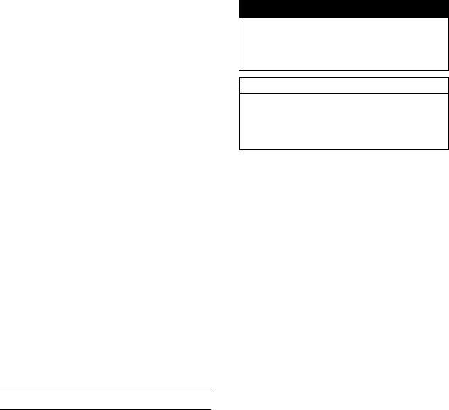
Battery Ground
Before completing any service on the motorcycle, disconnect the battery cables from the battery to prevent the engine from accidentally turning over. Disconnect the ground cable (–) first and then the positive (+). When completed with the service, first connect the positive (+) cable to the positive (+) terminal of the battery then the negative (–) cable to the negative terminal.
Edges of Parts
Lift large or heavy parts wearing gloves to prevent injury from possible sharp edges on the parts.
Solvent
Use a high-flash point solvent when cleaning parts. High -flash point solvent should be used according to directions of the solvent manufacturer.
Cleaning Vehicle before Disassembly
Clean the vehicle thoroughly before disassembly. Dirt or other foreign materials entering into sealed areas during vehicle disassembly can cause excessive wear and decrease performance of the vehicle.
GENERAL INFORMATION 1-3
Before Servicing
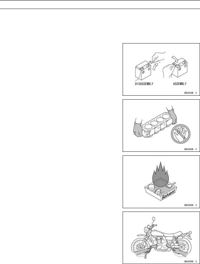
Arrangement and Cleaning of Removed Parts
Disassembled parts are easy to confuse. Arrange the parts according to the order the parts were disassembled and clean the parts in order prior to assembly.
Storage of Removed Parts
After all the parts including subassembly parts have been cleaned, store the parts in a clean area. Put a clean cloth or plastic sheet over the parts to protect from any foreign materials that may collect before re-assembly.
Inspection
Reuse of worn or damaged parts may lead to serious accident. Visually inspect removed parts for corrosion, discoloration, or other damage. Refer to the appropriate sections of this manual for service limits on individual parts. Replace the parts if any damage has been found or if the part is beyond its service limit.
Replacement Parts
Replacement parts must be KAWASAKI genuine or recommended by KAWASAKI. Gaskets, O-rings, oil seals, grease seals, circlips or cotter pins must be replaced with new ones whenever disassembled.
Assembly Order
In most cases assembly order is the reverse of disassembly, however, if assembly order is provided in this Service Manual, follow the procedures given.
1-4 GENERAL INFORMATION
Before Servicing
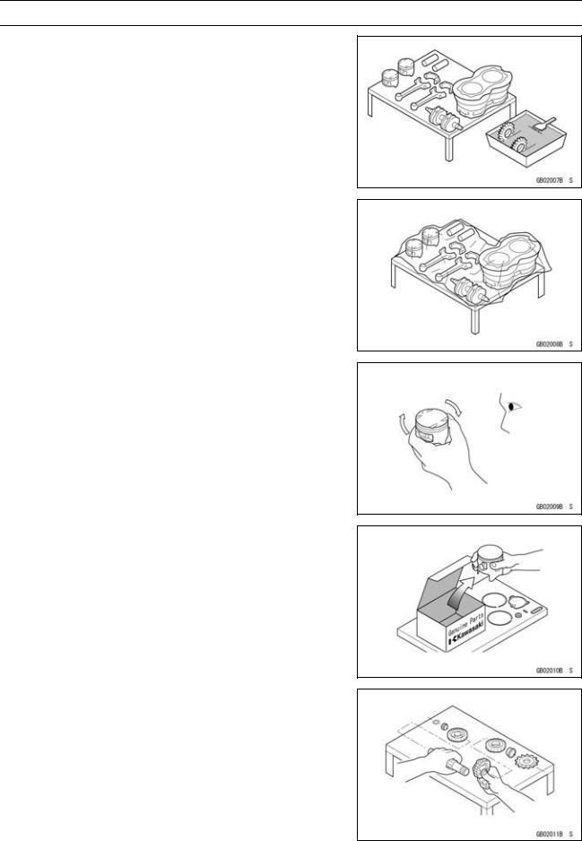
Tightening Sequence
Generally, when installing a part with several bolts, nuts, or screws, start them all in their holes and tighten them to a snug fit. Then tighten them according to the specified sequence to prevent case warpage or deformation which can lead to malfunction. Conversely when loosening the bolts, nuts, or screws, first loosen all of them by about a quarter turn and then remove them. If the specified tightening sequence is not indicated, tighten the fasteners alternating diagonally.
Tightening Torque
Incorrect torque applied to a bolt, nut, or screw may lead to serious damage. Tighten fasteners to the specified torque using a good quality torque wrench. Often, the tightening sequence is followed twice-initial tightening and final tightening with torque wrench.
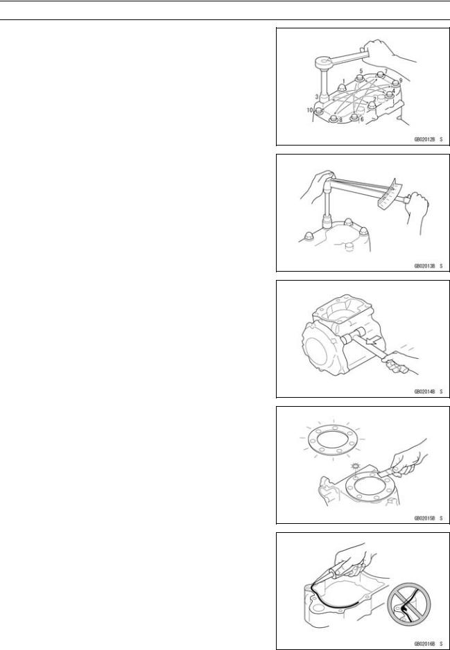
Force
Use common sense during disassembly and assembly, excessive force can cause expensive or hard to repair damage. When necessary, remove screws that have a non -permanent locking agent applied using an impact driver. Use a plastic-faced mallet whenever tapping is necessary.
Gasket, O-ring
Hardening, shrinkage, or damage of both gaskets and O-rings after disassembly can reduce sealing performance. Remove old gaskets and clean the sealing surfaces thoroughly so that no gasket material or other material remains. Install new gaskets and replace used O-rings when re-assembling
Liquid Gasket, Non-permanent Locking Agent
For applications that require Liquid Gasket or a Non-permanent Locking Agent, clean the surfaces so that no oil residue remains before applying liquid gasket or non-permanent locking agent. Do not apply them excessively. Excessive application can clog oil passages and cause serious damage.
GENERAL INFORMATION 1-5
Before Servicing
Press
For items such as bearings or oil seals that must be pressed into place, apply small amount of oil to the contact area. Be sure to maintain proper alignment and use smooth movements when installing.
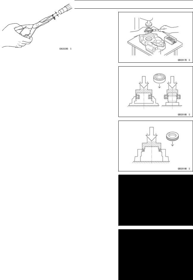
Ball Bearing and Needle Bearing
Do not remove pressed ball or needle unless removal is absolutely necessary. Replace with new ones whenever removed. Press bearings with the manufacturer and size marks facing out. Press the bearing into place by putting pressure on the correct bearing race as shown.
Pressing the incorrect race can cause pressure between the inner and outer race and result in bearing damage.
Oil Seal, Grease Seal
Do not remove pressed oil or grease seals unless removal is necessary. Replace with new ones whenever removed. Press new oil seals with manufacture and size marks facing out. Make sure the seal is aligned properly when installing.
Apply specified grease to the lip of seal before installing the seal.
Circlips, Cotter Pins
Replace circlips or cotter pins that were removed with new ones. Take care not to open the clip excessively when installing to prevent deformation.
1-6 GENERAL INFORMATION
Before Servicing
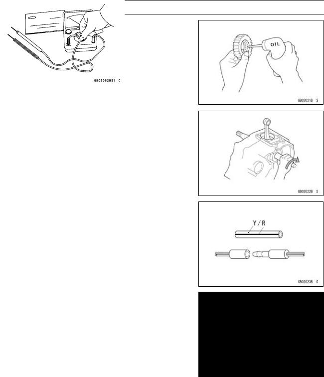
Lubrication
It is important to lubricate rotating or sliding parts during assembly to minimize wear during initial operation. Lubrication points are called out throughout this manual, apply the specific oil or grease as specified.
Direction of Engine Rotation
When rotating the crankshaft by hand, the free play amount of rotating direction will affect the adjustment. Rotate the crankshaft to positive direction (clockwise viewed from output side).
Electrical Leads
A two-color lead is identified first by the primary color and then the stripe color. Unless instructed otherwise, electrical leads must be connected to those of the same color.
Instrument
Use a meter that has enough accuracy for an accurate measurement. Read the manufacture’s instructions thoroughly before using the meter. Incorrect values may lead to improper adjustments.
GENERAL INFORMATION 1-7
Model Identification
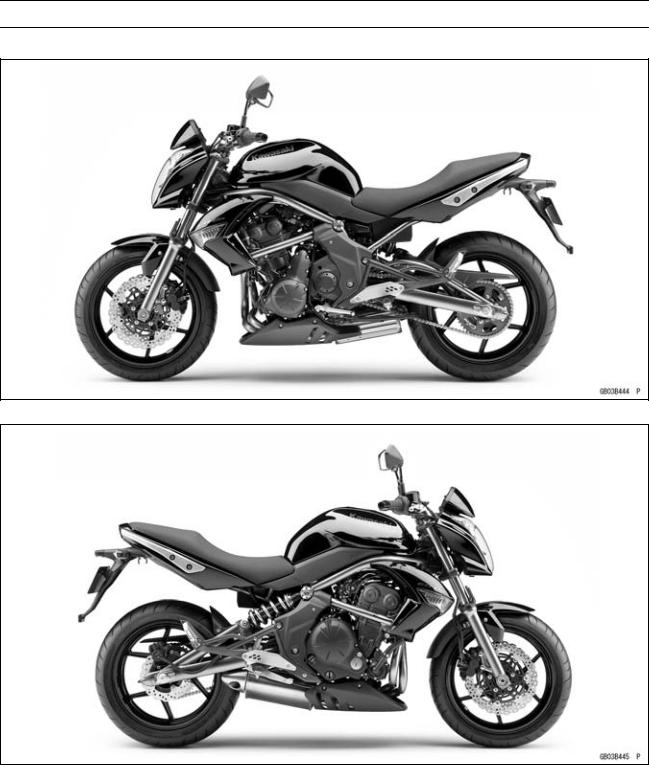
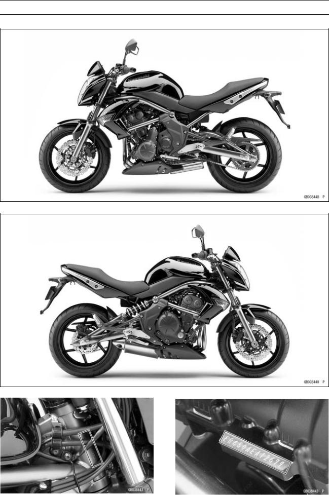
ER650C9F (EUR Models) Left Side View
ER650C9F (EUR Models) Right Side View
1-8 GENERAL INFORMATION
Model Identification
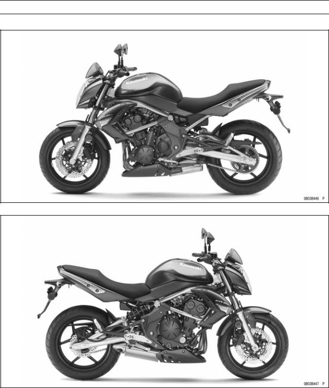
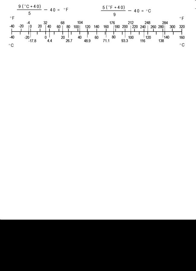
ER650C9F (US, CA Models) Left Side View
ER650C9F (US, CA Models) Right Side View
GENERAL INFORMATION 1-9
Model Identification
ER650D9F Left Side View
ER650D9F Right Side View
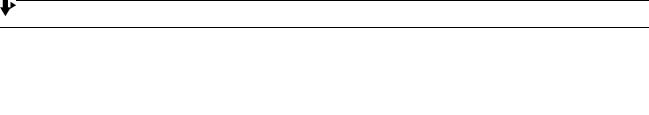
|
Frame Number |
Engine Number |
|

1-10 GENERAL INFORMATION
General Specifications
|
Items |
ER650C9F, ER650D9F |
|
|
Dimensions |
||
|
Overall Length |
2 100 mm (82.68 in.) |
|
|
Overall Width |
760 mm (29.9 in.) |
|
|
Overall Height |
1 100 mm (43.31 in.) |
|
|
Wheelbase |
1 405 mm (55.31 in.) |
|
|
Road Clearance |
140 mm (5.51 in.) |
|
|
Seat Height |
785 mm (30.9 in.) |
|
|
Curb Mass: |
||
|
ER650C Models: |
200 kg (441 lb) |
|
|
Front |
100 kg (221 lb) |
|
|
Rear |
100 kg (221 lb) |
|
|
ER650D Models: |
204 kg (450 lb) |
|
|
Front |
101 kg (223 lb) |
|
|
Rear |
103 kg (227 lb) |
|
|
Fuel Tank Capacity |
15.5 L (4.10 US gal.) |
|
|
Performance |
||
|
Minimum Turning Radius |
2.7 m (8.9 ft) |
|
|
Engine |
||
|
Type |
4-stroke, DOHC, 2-cylinder |
|
|
Cooling System |
Liquid-cooled |
|
|
Bore and Stroke |
83.0 × 60.0 mm (3.27 × 2.36 in.) |
|
|
Displacement |
649 cm³ (39.6 cu in.) |
|
|
Compression Ratio |
11.3 : 1 |
|
|
Maximum Horsepower |
53 kW (72 PS) @8 500 r/min (rpm) |
|
|
(MY) 52 kW (71 PS) @8 000 r/min (rpm) |
||
|
(US, CA, CAL) – – – |
||
|
Maximum Torque |
66 N·m (6.7 kgf·m, 49 ft·lb) @7 000 r/min (rpm) |
|
|
(US, CA, CAL) – – – |
||
|
Carburetion System |
FI (Fuel Injection), KEIHIN TTK38 × 2 |
|
|
Starting System |
Electric starter |
|
|
Ignition System |
Battery and coil (transistorized) |
|
|
Timing Advance |
Electronically advanced (IC igniter in ECU) |
|
|
Ignition Timing |
From 10° BTDC @1 300 r/min (rpm) |
|
|
To 34° BTDC @5 000 r/min (rpm) |
||
|
Spark Plug |
NGK CR9EIA-9 |
|
|
Cylinder Numbering Method |
Left to right, 1-2 |
|
|
Firing Order |
1-2 |
|
|
Valve Timing: |
||
|
Inlet: |
||
|
Open |
31° BTDC |
|
|
Close |
61° ABDC |
|
|
Duration |
272° |
|
|
GENERAL INFORMATION 1-11 |
|
|
General Specifications |
|
|
Items |
ER650C9F, ER650D9F |
|
Exhaust: |
|
|
Open |
50° BBDC |
|
Close |
30° ATDC |
|
Duration |
260° |
|
Lubrication System |
Forced lubrication (semi-dry sump) |
|
Engine Oil: |
|
|
Grade |
API SE, SF or SG |
|
API SH, SJ, SL or SM with JASO MA, MA1 or MA2 |
|
|
Viscosity |
SAE 10W-40 |
|
Capacity |
2.4 L (2.5 US qt) |
|
Drive Train |
|
|
Primary Reduction System: |
|
|
Type |
Gear |
|
Reduction Ratio |
2.095 (88/42) |
|
Clutch Type |
Wet multi disc |
|
Transmission: |
|
|
Type |
6-speed, constant mesh, return shift |
|
Gear Ratios: |
|
|
1st |
2.438 (39/16) |
|
2nd |
1.714 (36/21) |
|
3rd |
1.333 (32/24) |
|
4th |
1.111 (30/27) |
|
5th |
0.966 (28/29) |
|
6th |
0.852 (23/27) |
|
Final Drive System: |
|
|
Type |
Chain drive |
|
Reduction Ratio |
3.067 (46/15) |
|
Overall Drive Ratio |
5.473 @Top gear |
|
Frame |
|
|
Type |
Tubular, diamond |
|
Caster (Rake Angle) |
24.5° |
|
Trail |
102 mm (4.02 in.) |
|
Front Tire: |
|
|
Type |
Tubeless |
|
Size |
120/70 ZR17 M/C (58W) |
|
Rim Size |
17 × 3.50 |
|
Rear Tire: |
|
|
Type |
Tubeless |
|
Size |
160/60 ZR17 M/C (69W) |
|
Rim Size |
17 × 4.50 |
|
Front Suspension: |
|
|
Type |
Telescopic fork |
|
Wheel Travel |
120 mm (4.72 in.) |

1-12 GENERAL INFORMATION
General Specifications
|
Items |
ER650C9F, ER650D9F |
|
Rear Suspension: |
|
|
Type |
Swingarm |
|
Wheel Travel |
125 mm (4.92 in.) |
|
Brake Type: |
|
|
Front |
Dual discs |
|
Rear |
Single disc |
|
Electrical Equipment |
|
|
Battery |
12 V 10 Ah |
|
Headlight: |
|
|
Type |
Semi-sealed beam |
|
Bulb: |
|
|
High |
12 V 55 W + 55 W (quartz-halogen) |
|
Low |
12 V 55 W (quartz-halogen) |
|
Tail/Brake Light |
LED |
|
Alternator: |
|
|
Type |
Three-phase AC |
|
Rated Output |
24 A/14 V @5 000 r/min (rpm) |
Specifications are subject to change without notice, and may not apply to every country.
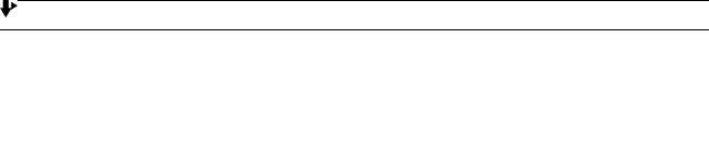
GENERAL INFORMATION 1-13
Unit Conversion Table
|
Prefixes for Units: |
Units of Length: |
|
Prefix |
Symbol |
Power |
||
|
mega |
M |
× 1 000 |
000 |
|
|
kilo |
k |
× |
1 000 |
|
|
centi |
c |
× |
0.01 |
|
|
milli |
m |
× |
0.001 |
|
|
micro |
µ |
× |
0.000001 |
Units of Mass:
|
kg |
× |
2.205 |
= |
lb |
|
g |
× |
0.03527 |
= |
oz |
Units of Volume:
|
L |
× |
0.2642 |
= |
gal (US) |
|
L |
× |
0.2200 |
= |
gal (imp) |
|
L |
× |
1.057 |
= |
qt (US) |
|
L |
× |
0.8799 |
= |
qt (imp) |
|
L |
× |
2.113 |
= |
pint (US) |
|
L |
× |
1.816 |
= |
pint (imp) |
|
mL |
× |
0.03381 |
= |
oz (US) |
|
mL |
× |
0.02816 |
= |
oz (imp) |
|
mL |
× |
0.06102 |
= |
cu in |
Units of Force:
|
km |
× |
0.6214 |
= |
mile |
|
m |
× |
3.281 |
= |
ft |
|
mm |
× |
0.03937 |
= |
in |
Units of Torque:
|
N·m |
× |
0.1020 |
= |
kgf·m |
|
N·m |
× |
0.7376 |
= |
ft·lb |
|
N·m |
× |
8.851 |
= |
in·lb |
|
kgf·m |
× |
9.807 |
= |
N·m |
|
kgf·m |
× |
7.233 |
= |
ft·lb |
|
kgf·m |
× |
86.80 |
= |
in·lb |
Units of Pressure:
|
kPa |
× |
0.01020 |
= |
kgf/cm² |
|
kPa |
× |
0.1450 |
= |
psi |
|
kPa |
× |
0.7501 |
= |
cmHg |
|
kgf/cm² |
× |
98.07 |
= |
kPa |
|
kgf/cm² |
× |
14.22 |
= |
psi |
|
cmHg |
× |
1.333 |
= |
kPa |
Units of Speed:
km/h × 0.6214 = mph
Units of Power:
|
N |
× |
0.1020 |
= |
kg |
kW |
× |
1.360 |
= |
PS |
||
|
N |
× |
0.2248 |
= |
lb |
|||||||
|
kW |
× |
1.341 |
= |
HP |
|||||||
|
kg |
× |
9.807 |
= |
N |
|||||||
|
PS |
× |
0.7355 |
= |
kW |
|||||||
|
kg |
× |
2.205 |
= |
lb |
|||||||
|
PS |
× |
0.9863 |
= |
HP |
|||||||
Units of Temperature:

PERIODIC MAINTENANCE 2-1
Periodic Maintenance
Table of Contents
|
Periodic Maintenance Chart ……………………………………………………………………………………… |
2-3 |
||
|
2 |
|||
|
Torque and Locking Agent………………………………………………………………………………………… |
2-6 |
||
|
Specifications |
2-12 |
||
|
Special Tools ………………………………………………………………………………………………………….. |
2-14 |
||
|
Periodic Maintenance Procedures……………………………………………………………………………… |
2-15 |
||
|
Fuel System (DFI)…………………………………………………………………………………………………. |
2-15 |
||
|
Air Cleaner Element Cleaning………………………………………………………………………………. |
2-15 |
||
|
Throttle Control System Inspection……………………………………………………………………….. |
2-16 |
||
|
Engine Vacuum Synchronization Inspection…………………………………………………………… |
2-16 |
||
|
Idle Speed Inspection …………………………………………………………………………………………. |
2-18 |
||
|
Idle Speed Adjustment………………………………………………………………………………………… |
2-19 |
||
|
Fuel Hose Inspection (fuel leak, damage, installation condition) ……………………………….. |
2-19 |
||
|
Evaporative Emission Control System Inspection (CAL, SEA and TH Models) …………… |
2-19 |
||
|
Cooling System…………………………………………………………………………………………………….. |
2-20 |
||
|
Coolant Level Inspection……………………………………………………………………………………… |
2-20 |
||
|
Water Hose Damage and Installation Condition Inspection………………………………………. |
2-21 |
||
|
Engine Top End ……………………………………………………………………………………………………. |
2-21 |
||
|
Valve Clearance Inspection …………………………………………………………………………………. |
2-21 |
||
|
Valve Clearance Adjustment………………………………………………………………………………… |
2-22 |
||
|
Air Suction System Damage Inspection…………………………………………………………………. |
2-25 |
||
|
Clutch………………………………………………………………………………………………………………….. |
2-25 |
||
|
Clutch Operation Inspection…………………………………………………………………………………. |
2-25 |
||
|
Wheels/Tires………………………………………………………………………………………………………… |
2-26 |
||
|
Air Pressure Inspection……………………………………………………………………………………….. |
2-26 |
||
|
Wheel/Tire Damage Inspection…………………………………………………………………………….. |
2-26 |
||
|
Tire Tread Wear, Abnormal Wear Inspection ………………………………………………………….. |
2-26 |
||
|
Wheel Bearing Damage Inspection ………………………………………………………………………. |
2-27 |
||
|
Final Drive……………………………………………………………………………………………………………. |
2-28 |
||
|
Drive Chain Lubrication Condition Inspection …………………………………………………………. |
2-28 |
||
|
Drive Chain Slack Inspection ……………………………………………………………………………….. |
2-28 |
||
|
Drive Chain Slack Adjustment ……………………………………………………………………………… |
2-29 |
||
|
Wheel Alignment Inspection ………………………………………………………………………………… |
2-30 |
||
|
Drive Chain Wear Inspection ……………………………………………………………………………….. |
2-30 |
||
|
Chain Guide Inspection……………………………………………………………………………………….. |
2-31 |
||
|
Brake System ………………………………………………………………………………………………………. |
2-31 |
||
|
Brake Fluid Leak (Brake Hose and Pipe) Inspection ……………………………………………….. |
2-31 |
||
|
Brake Hose and Pipe Damage and Installation Condition Inspection…………………………. |
2-32 |
||
|
Brake Fluid Level Inspection………………………………………………………………………………… |
2-32 |
||
|
Brake Pad Wear Inspection …………………………………………………………………………………. |
2-33 |
||
|
Brake Operation Inspection …………………………………………………………………………………. |
2-34 |
||
|
Brake Light Switch Operation Inspection ……………………………………………………………….. |
2-34 |
||
|
Suspensions ………………………………………………………………………………………………………… |
2-35 |
||
|
Front Forks/Rear Shock Absorber Operation Inspection ………………………………………….. |
2-35 |
||
|
Front Fork Oil Leak Inspection……………………………………………………………………………… |
2-35 |
||
|
Rear Shock Absorber Oil Leak Inspection ……………………………………………………………… |
2-35 |
||
|
Steering System …………………………………………………………………………………………………… |
2-36 |
||
|
Steering Play Inspection ……………………………………………………………………………………… |
2-36 |
||
|
Steering Play Adjustment…………………………………………………………………………………….. |
2-36 |
||
|
Steering Stem Bearing Lubrication ……………………………………………………………………….. |
2-37 |
||
|
Electrical System ………………………………………………………………………………………………….. |
2-38 |

2-2 PERIODIC MAINTENANCE
|
Lights and Switches Operation Inspection……………………………………………………………… |
2-38 |
|
Headlight Aiming Inspection ………………………………………………………………………………… |
2-40 |
|
Sidestand Switch Operation Inspection …………………………………………………………………. |
2-41 |
|
Engine Stop Switch Operation Inspection………………………………………………………………. |
2-42 |
|
Others …………………………………………………………………………………………………………………. |
2-43 |
|
Chassis Parts Lubrication ……………………………………………………………………………………. |
2-43 |
|
Bolts, Nuts and Fasteners Tightness Inspection……………………………………………………… |
2-44 |
|
Replacement Parts ……………………………………………………………………………………………….. |
2-45 |
|
Air Cleaner Element Replacement………………………………………………………………………… |
2-45 |
|
Fuel Hose Replacement ……………………………………………………………………………………… |
2-45 |
|
Coolant Change …………………………………………………………………………………………………. |
2-46 |
|
Radiator Hose and O-ring Replacement………………………………………………………………… |
2-48 |
|
Engine Oil Change……………………………………………………………………………………………… |
2-48 |
|
Oil Filter Replacement ………………………………………………………………………………………… |
2-49 |
|
Brake Hose and Pipe Replacement………………………………………………………………………. |
2-50 |
|
Brake Fluid Change ……………………………………………………………………………………………. |
2-51 |
|
Master Cylinder Rubber Parts Replacement ………………………………………………………….. |
2-52 |
|
Caliper Rubber Parts Replacement ………………………………………………………………………. |
2-53 |
|
Spark Plug Replacement …………………………………………………………………………………….. |
2-56 |

PERIODIC MAINTENANCE 2-3
Periodic Maintenance Chart
The scheduled maintenance must be done in accordance with this chart to keep the motorcycle in good running condition.The initial maintenance is vitally important and must not be neglected.
Periodic Inspection
|
FREQUENCY |
Whichever |
* ODOMETER READING |
|||||||||||||
|
comes first |
× 1 000 km |
See |
|||||||||||||
|
(× 1 000 mile) |
|||||||||||||||
|
Page |
|||||||||||||||
|
1 |
6 |
12 |
18 |
24 |
30 |
36 |
|||||||||
|
ITEM |
Every |
(0.6) |
(3.75) |
(7.5) |
(11.25) |
(15) |
(18.75) |
(22.5) |
|||||||
|
Fuel System |
|||||||||||||||
|
Air cleaner element — clean |
• |
• |
• |
2–15 |
|||||||||||
|
Throttle control system (play, |
year |
• |
• |
• |
• |
2–16 |
|||||||||
|
smooth return, no drag) — inspect |
|||||||||||||||
|
Engine vacuum synchronization |
• |
• |
• |
2–16 |
|||||||||||
|
— inspect |
|||||||||||||||
|
Idle speed — inspect |
• |
• |
• |
• |
2–18 |
||||||||||
|
Fuel leak (fuel hose and pipe) — |
year |
• |
• |
• |
• |
2–19 |
|||||||||
|
inspect |
|||||||||||||||
|
Fuel hose and pipe damage — |
year |
• |
• |
• |
• |
2–19 |
|||||||||
|
inspect |
|||||||||||||||
|
Fuel hose and pipe installation |
year |
• |
• |
• |
• |
2–19 |
|||||||||
|
condition — inspect |
|||||||||||||||
|
Evaporative emission control |
• |
• |
• |
• |
• |
• |
• |
||||||||
|
system function (CAL, TH, SEA |
2–19 |
||||||||||||||
|
Models) — inspection |
|||||||||||||||
|
Cooling System |
|||||||||||||||
|
Coolant level — inspect |
• |
• |
• |
• |
2–20 |
||||||||||
|
Coolant leak (water hose and |
year |
• |
• |
• |
• |
2–21 |
|||||||||
|
pipe) — inspect |
|||||||||||||||
|
Water hose damage — inspect |
year |
• |
• |
• |
• |
2–21 |
|||||||||
|
Water hose installation condition |
year |
• |
• |
• |
• |
2–21 |
|||||||||
|
— inspect |
|||||||||||||||
|
Engine Top End |
|||||||||||||||
|
Valve |
US, CA, CAL |
• |
|||||||||||||
|
clearance — |
Models |
2–21 |
|||||||||||||
|
inspect |
Other than US, |
Every 42 000 km (26 250 mile) |
|||||||||||||
|
CA, CAL Models |
|||||||||||||||
|
Air suction system damage — |
• |
• |
• |
2–25 |
|||||||||||
|
inspect |
|||||||||||||||
|
Clutch |
|||||||||||||||
|
Clutch operation (play, |
• |
• |
• |
• |
|||||||||||
|
disengagement, engagement) — |
2–25 |
||||||||||||||
|
inspect |
|||||||||||||||
|
Wheels and Tires |
|||||||||||||||
|
Tire air pressure — inspect |
year |
• |
• |
• |
2–26 |
||||||||||
|
Wheel/tire damage — inspect |
• |
• |
• |
2–26 |
|||||||||||
|
Tire tread wear, abnormal wear |
• |
• |
• |
2–26 |
|||||||||||
|
— inspect |
|||||||||||||||
|
Wheel bearing damage — inspect |
year |
• |
• |
• |
2–27 |
2-4 PERIODIC MAINTENANCE
Periodic Maintenance Chart
|
FREQUENCY |
Whichever |
* ODOMETER READING |
|||||||||||||
|
comes first |
× 1 000 km |
See |
|||||||||||||
|
(× 1 000 mile) |
|||||||||||||||
|
Page |
|||||||||||||||
|
1 |
6 |
12 |
18 |
24 |
30 |
36 |
|||||||||
|
ITEM |
Every |
(0.6) |
(3.75) |
(7.5) |
(11.25) |
(15) |
(18.75) |
(22.5) |
|||||||
|
Final Drive |
|||||||||||||||
|
Drive chain lubrication condition |
Every 600 km (400 mile) |
2–28 |
|||||||||||||
|
— inspect # |
|||||||||||||||
|
Drive chain slack — inspect # |
Every 1 000 km (600 mile) |
2–28 |
|||||||||||||
|
Drive chain wear — inspect # |
• |
• |
• |
2–30 |
|||||||||||
|
Chain guide wear — inspect |
• |
• |
• |
2–31 |
|||||||||||
|
Brakes |
|||||||||||||||
|
Brake fluid leak (brake hose and |
year |
• |
• |
• |
• |
• |
• |
• |
2–31 |
||||||
|
pipe) — inspect |
|||||||||||||||
|
Brake hose and pipe damage — |
year |
• |
• |
• |
• |
• |
• |
• |
2–32 |
||||||
|
inspect |
|||||||||||||||
|
Brake hose and pipe installation |
year |
• |
• |
• |
• |
• |
• |
• |
2–32 |
||||||
|
condition — inspect |
|||||||||||||||
|
Brake fluid level — inspect |
6 months |
• |
• |
• |
• |
• |
• |
• |
2–32 |
||||||
|
Brake pad wear — inspect # |
• |
• |
• |
• |
• |
• |
2–33 |
||||||||
|
Brake operation (effectiveness, |
year |
• |
• |
• |
• |
• |
• |
• |
2–34 |
||||||
|
play, no drag) — inspect |
|||||||||||||||
|
Brake light switch operation — |
• |
• |
• |
• |
• |
• |
• |
2–34 |
|||||||
|
inspect |
|||||||||||||||
|
Suspension |
|||||||||||||||
|
Front forks/rear shock absorber |
• |
• |
• |
||||||||||||
|
operation (damping and smooth |
2–35 |
||||||||||||||
|
stroke) — inspect |
|||||||||||||||
|
Front forks/rear shock absorber |
year |
• |
• |
• |
2–35 |
||||||||||
|
oil leak — inspect |
|||||||||||||||
|
Steering |
|||||||||||||||
|
Steering play — inspect |
year |
• |
• |
• |
• |
2–36 |
|||||||||
|
Steering stem bearings — |
2 years |
• |
2–37 |
||||||||||||
|
lubricate |
|||||||||||||||
|
Electrical System |
|||||||||||||||
|
Lights and switches operation — |
year |
• |
• |
• |
2–38 |
||||||||||
|
inspect |
|||||||||||||||
|
Headlight aiming — inspect |
year |
• |
• |
• |
2–40 |
||||||||||
|
Sidestand switch operation — |
year |
• |
• |
• |
2–41 |
||||||||||
|
inspect |
|||||||||||||||
|
Engine stop switch operation — |
year |
• |
• |
• |
2–42 |
||||||||||
|
inspect |
|||||||||||||||
|
Others |
|||||||||||||||
|
Chassis parts — lubricate |
year |
• |
• |
• |
2–43 |
||||||||||
|
Bolts and nuts tightness — inspect |
• |
• |
• |
• |
2–44 |
#: Service more frequently when operating in severe conditions; dusty, wet, muddy, high speed or frequent starting/stopping.
*: For higher odometer readings, repeat at the frequency interval established here.
PERIODIC MAINTENANCE 2-5
Periodic Maintenance Chart
Periodic Replacement Parts
|
FREQUENCY |
Whichever |
* ODOMETER |
|||||||||
|
comes |
READING |
||||||||||
|
× 1 000 km |
See |
||||||||||
|
first |
|||||||||||
|
(× 1 000 mile) |
|||||||||||
|
Page |
|||||||||||
|
1 |
12 |
24 |
36 |
48 |
|||||||
|
ITEM |
Every |
(0.6) |
(7.5) |
(15) |
(22.5) |
(30) |
|||||
|
Air cleaner element # — replace |
2 years |
2–45 |
|||||||||
|
Fuel hose — replace |
4 years |
• |
2–45 |
||||||||
|
Coolant — change |
3 years |
• |
2–46 |
||||||||
|
Radiator hose and O-ring — replace |
3 years |
• |
2–48 |
||||||||
|
Engine oil # — change |
year |
• |
• |
• |
• |
• |
2–48 |
||||
|
Oil filter — replace |
year |
• |
• |
• |
• |
• |
2–49 |
||||
|
Brake hose and pipe — replace |
4 years |
• |
2–50 |
||||||||
|
Brake fluid — change |
2 years |
• |
• |
2–51 |
|||||||
|
Rubber parts of master cylinder and caliper — replace |
4 years |
• |
2–52 |
||||||||
|
Spark plug — replace |
• |
• |
• |
• |
2–56 |
#: Service more frequently when operating in severe conditions; dusty, wet, muddy, high speed or frequent starting/stopping.
*: For higher odometer readings, repeat at the frequency interval established here.

2-6 PERIODIC MAINTENANCE
Torque and Locking Agent
The following tables list the tightening torque for the major fasteners requiring use of a non-permanent locking agent or silicone sealant etc.
Letters used in the “Remarks” column mean:
AL: Tighten the two clamp bolts alternately two times to ensure even tightening torque. EO: Apply engine oil.
L: Apply a non-permanent locking agent to the threads. Lh: Left-hand Threads
MO: Apply molybdenum disulfide oil solution.
(mixture of the engine oil and molybdenum disulfide grease in a weight ratio 10 : 1)
R:Replacement Parts
S:Follow the specified tightening sequence. Si: Apply silicone grease (ex. PBC grease).
SS:Apply silicone sealant.
|
Fastener |
Torque |
Remarks |
|||||
|
N·m |
kgf·m |
ft·lb |
|||||
|
Fuel System (DFI) |
|||||||
|
Crankshaft Sensor Bolts |
6.0 |
0.61 |
53 in·lb |
||||
|
Fuel Level Sensor Bolts |
6.9 |
0.70 |
61 in·lb |
L |
|||
|
Fuel Pump Bolts |
9.8 |
1.0 |
87 in·lb |
L, S |
|||
|
Oxygen Sensor (Equipped Models) |
44 |
4.5 |
32 |
||||
|
Speed Sensor Bolt |
7.8 |
0.80 |
69 in·lb |
L |
|||
|
Speed Sensor Bracket Bolts |
1.0 |
87 in·lb |
|||||
|
9.8 |
|||||||
|
Switch Housing Screws |
3.5 |
0.36 |
31 in·lb |
||||
|
Timing Rotor Bolt |
40 |
4.1 |
30 |
||||
|
Water Temperature Sensor |
12 |
1.2 |
106 in·lb |
||||
|
Cooling System |
|||||||
|
Baffle Plate Bolts |
5.9 |
0.60 |
52 in·lb |
||||
|
Radiator Bolt |
15 |
1.5 |
11 |
||||
|
Water Hose Clamp Screws |
2.0 |
0.20 |
18 in·lb |
||||
|
Thermostat Housing Bolts |
9.8 |
1.0 |
87 in·lb |
||||
|
Water Pump Cover Bolts |
87 in·lb |
||||||
|
9.8 |
1.0 |
||||||
|
Water Pump Drain Bolt |
9.8 |
1.0 |
87 in·lb |
||||
|
Water Pump Impeller Bolt |
9.8 |
1.0 |
87 in·lb |
||||
|
Water Temperature Sensor |
12 |
1.2 |
106 in·lb |
||||
|
Engine Top End |
|||||||
|
Air Suction Valve Cover Bolts |
9.8 |
1.0 |
87 in·lb |
||||
|
Baffle Plate Bolts |
5.9 |
0.60 |
52 in·lb |
||||
|
Camshaft Cap Bolts |
12 |
1.2 |
106 in·lb |
S |
|||
|
Camshaft Chain Tensioner Cap Bolt |
20 |
2.0 |
15 |
||||
|
Camshaft Chain Tensioner Mounting Bolts |
9.8 |
1.0 |
87 in·lb |
||||
|
Camshaft Sprocket Bolts |
15 |
1.5 |
11 |
L |
|||
|
Cylinder Head Bolts (M10) |
56 |
5.7 |
41 |
MO, S |
|||
|
Cylinder Head Bolts (M6) |
12 |
1.2 |
106 in·lb |
S |
|||
|
Cylinder Head Cover Bolts |
9.8 |
1.0 |
87 in·lb |
||||
|
Rear Camshaft Chain Guide Bolts |
20 |
2.0 |
15 |
L |
|||
|
Spark Plugs |
15 |
1.5 |
11 |
||||
![]()
PERIODIC MAINTENANCE 2-7
Torque and Locking Agent
|
Fastener |
Torque |
Remarks |
|||
|
N·m |
kgf·m |
ft·lb |
|||
|
Throttle Body Assy Holder Bolts |
12 |
1.2 |
106 in·lb |
||
|
Cylinder Bolt (M8) |
27.5 |
2.8 |
20 |
MO, S |
|
|
Cylinder Nut |
49 |
5.0 |
36 |
MO, S |
|
|
Cylinder Bolts (M6) |
106 in·lb |
S |
|||
|
12 |
1.2 |
||||
|
Exhaust Pipe Manifold Holder Nuts |
17 |
1.7 |
13 |
||
|
Muffler Body Mounting Bolt (Front) |
20 |
2.0 |
15 |
||
|
Muffler Body Mounting Bolt (Rear) |
20 |
2.0 |
15 |
||
|
Clutch |
|||||
|
Clutch Cable Clamp Bracket Bolt |
9.8 |
1.0 |
87 in·lb |
||
|
Clutch Cable Holder Bolts |
9.8 |
1.0 |
87 in·lb |
L |
|
|
Clutch Cover Bolts |
9.8 |
1.0 |
87 in·lb |
||
|
Clutch Hub Nut |
130 |
13.3 |
96 |
R |
|
|
Clutch Lever Clamp Bolts |
7.8 |
0.80 |
69 in·lb |
S |
|
|
Clutch Spring Bolts |
9.8 |
1.0 |
87 in·lb |
||
|
Timing Rotor Bolt Cap |
4.9 |
0.50 |
43 in·lb |
||
|
Oil Filler Plug |
– |
– |
– |
Hand-tighten |
|
|
Oil Pump Chain Guide Bolts |
12 |
1.2 |
106 in·lb |
L (1) |
|
|
Oil Pump Sprocket Bolt |
12 |
1.2 |
106 in·lb |
L, Lh |
|
|
Timing Inspection Cap |
3.9 |
0.40 |
35 in·lb |
||
|
Engine Lubrication System |
|||||
|
Engine Oil Drain Plug |
30 |
3.1 |
22 |
||
|
Filter Plate Bolts |
9.8 |
1.0 |
87 in·lb |
L |
|
|
Holder Mounting Bolt |
25 |
2.5 |
18 |
L |
|
|
Lower Fairing Bracket Bolts |
12 |
1.2 |
106 in·lb |
L |
|
|
Oil Filter |
17.5 |
1.8 |
13 |
EO, R |
|
|
Oil Pan Bolts |
12 |
1.2 |
106 in·lb |
S |
|
|
Oil Passage Plug |
20 |
2.0 |
15 |
L |
|
|
Oil Passage Plug (M6) |
3.9 |
0.40 |
35 in·lb |
||
|
Oil Pipe Plate Bolt |
9.8 |
1.0 |
87 in·lb |
L |
|
|
Oil Plate Bolts |
9.8 |
1.0 |
87 in·lb |
L |
|
|
Oil Pressure Relief Valve |
15 |
1.5 |
11 |
L |
|
|
Oil Pressure Switch |
15 |
1.5 |
11 |
SS |
|
|
Oil Pump Chain Guide Bolts |
12 |
1.2 |
106 in·lb |
L (1) |
|
|
Oil Pump Cover Bolts |
9.8 |
1.0 |
87 in·lb |
L |
|
|
Oil Pump Sprocket Bolt |
12 |
1.2 |
106 in·lb |
L, Lh |
|
|
Engine Removal/Installation |
|||||
|
Engine Bracket Bolts (Left) |
25 |
2.5 |
18 |
S |
|
|
Engine Bracket Bolts (Right) |
25 |
2.5 |
18 |
S |
|
|
Engine Mounting Nut (Lower) |
44 |
4.5 |
32 |
S |
|
|
Engine Mounting Nut (Rear) |
44 |
4.5 |
32 |
S |
|
|
Engine Mounting Bolt (Left) |
44 |
4.5 |
32 |
S |
|
|
Engine Mounting Bolt (Right) |
44 |
4.5 |
32 |
S |
|

2-8 PERIODIC MAINTENANCE
Torque and Locking Agent
|
Fastener |
Torque |
Remarks |
|||||
|
N·m |
kgf·m |
ft·lb |
|||||
|
Crankshaft/Transmission |
|||||||
|
Breather Plate Bolts |
9.8 |
1.0 |
87 in·lb |
L |
|||
|
Race Holder Screw |
4.9 |
0.50 |
43 in·lb |
L |
|||
|
Connecting Rod Big End Nuts |
see Text |
← |
← |
MO |
|||
|
Crankcase Bolt (M8, L = 110 mm) |
27.5 |
2.8 |
20 |
S |
|||
|
Crankcase Bolt (M6, L = 32 mm) |
19.6 |
2.0 |
14 |
S |
|||
|
Crankcase Bolts (M6, L = 38 mm) |
19.6 |
2.0 |
14 |
S |
|||
|
Crankcase Bolts (M6, L = 45 mm) |
19.6 |
2.0 |
14 |
S |
|||
|
Crankcase Bolt (M8, L = 50 mm) |
27.5 |
2.8 |
20 |
S |
|||
|
Crankcase Bolts (M8, L = 60 mm) |
35 |
3.6 |
26 |
MO, S |
|||
|
Crankcase Bolt (M8, L = 60 mm) |
27.5 |
2.8 |
20 |
S |
|||
|
Crankcase Bolts (M8, L = 73 mm) |
35 |
3.6 |
26 |
MO, S |
|||
|
Crankcase Bolts (M9, L = 113 mm) |
44 |
4.5 |
32 |
MO, S |
|||
|
Crankcase Bolts (M9, L = 83 mm) |
44 |
4.5 |
32 |
MO, S |
|||
|
Upper Crankcase Bolt (M8, L = 120 mm) |
27.5 |
2.8 |
20 |
S |
|||
|
Upper Crankcase Bolts (M8, L = 110 mm) |
27.5 |
2.8 |
20 |
S |
|||
|
Oil Pipe Bolts |
9.8 |
1.0 |
87 in·lb |
L |
|||
|
Oil Plate Bolts |
9.8 |
1.0 |
87 in·lb |
L |
|||
|
Shift Shaft Return Spring Pin |
29 |
3.0 |
21 |
L |
|||
|
Timing Rotor Bolt |
40 |
4.1 |
30 |
||||
|
Drive Shaft Bearing Holder Screw |
4.9 |
0.50 |
43 in·lb |
L |
|||
|
Gear Positioning Lever Bolt |
12 |
1.2 |
106 in·lb |
L |
|||
|
Neutral Switch |
15 |
1.5 |
11 |
||||
|
Neutral Switch Holder Screw |
4.9 |
0.50 |
43 in·lb |
L |
|||
|
Transmission Case Oil Nozzle |
2.9 |
0.30 |
26 in·lb |
L |
|||
|
Shift Drum Bearing Holder Screws |
4.9 |
0.50 |
43 in·lb |
L |
|||
|
Shift Drum Cam Bolt |
12 |
1.2 |
106 in·lb |
L |
|||
|
Shift Lever Bolt |
12 |
1.2 |
106 in·lb |
||||
|
Shift Rod Plate Bolt |
9.8 |
1.0 |
87 in·lb |
L |
|||
|
Shift Shaft Cover Bolts |
9.8 |
1.0 |
87 in·lb |
L (3) |
|||
|
Shift Shaft Cover Screw |
4.9 |
0.50 |
43 in·lb |
L, S |
|||
|
Transmission Case Bolts |
20 |
2.0 |
15 |
||||
|
Wheels/Tires |
|||||||
|
Front Axle |
108 |
11.0 |
80 |
||||
|
Front Axle Clamp Bolt |
34 |
3.5 |
25 |
||||
|
Rear Axle Nut |
108 |
11.0 |
80 |
||||
|
Final Drive |
|||||||
|
Engine Sprocket Nut |
125 |
12.7 |
92 |
MO |
|||
|
Rear Axle Nut |
108 |
11.0 |
80 |
||||
|
Rear Sprocket Nuts |
59 |
6.0 |
44 |
||||
|
Speed Sensor Bolt |
7.8 |
0.80 |
69 in·lb |
L |
|||
|
Speed Sensor Bracket Bolts |
9.8 |
1.0 |
87 in·lb |
||||

PERIODIC MAINTENANCE 2-9
Torque and Locking Agent
|
Fastener |
Torque |
Remarks |
|||
|
N·m |
kgf·m |
ft·lb |
|||
|
Brakes |
|||||
|
Caliper Bleed Valve |
7.8 |
0.80 |
69 in·lb |
||
|
Brake Hose Banjo Bolts |
25 |
2.5 |
18 |
||
|
Brake Lever Pivot Bolt |
1.0 |
0.10 |
9 in·lb |
Si |
|
|
Brake Lever Pivot Bolt Locknut |
5.9 |
0.60 |
52 in·lb |
||
|
Brake Disc Mounting Bolts |
27 |
2.8 |
20 |
L |
|
|
Front Brake Light Switch Screw |
1.2 |
0.12 |
11 in·lb |
||
|
Front Brake Reservoir Cap Screws |
1.5 |
0.15 |
13 in·lb |
||
|
Front Caliper Mounting Bolts |
34 |
3.5 |
25 |
||
|
Front Master Cylinder Clamp Bolts |
11 |
1.1 |
97 in·lb |
S |
|
|
Brake Pedal Bolt |
8.8 |
0.90 |
78 in·lb |
||
|
Rear Caliper Mounting Bolts |
25 |
2.5 |
18 |
||
|
Rear Master Cylinder Mounting Bolts |
25 |
2.5 |
18 |
||
|
Rear Master Cylinder Push Rod Locknut |
17 |
1.7 |
13 |
||
|
Brake Pipe Joint Nuts (ER650D Models) |
18 |
1.8 |
13 |
||
|
Wheel Rotation Sensor Bolts (ER650D Models) |
|||||
|
20 |
2.0 |
15 |
|||
|
Suspension |
|||||
|
Front Axle Clamp Bolt |
34 |
3.5 |
25 |
||
|
Front Fork Bottom Allen Bolts |
30 |
3.1 |
22 |
L |
|
|
Front Fork Clamp Bolts (Lower) |
20 |
2.0 |
15 |
AL |
|
|
Front Fork Clamp Bolts (Upper) |
20 |
2.0 |
15 |
||
|
Front Fork Top Plugs |
25 |
2.5 |
18 |
||
|
Rear Shock Absorber Bolts |
59 |
6.0 |
44 |
||
|
Swingarm Pivot Shaft Nut |
108 |
11.0 |
80 |
||
|
Steering |
|||||
|
Front Fork Clamp Bolts (Lower) |
20 |
2.0 |
15 |
AL |
|
|
Front Fork Clamp Bolts (Upper) |
20 |
2.0 |
15 |
||
|
Handlebar Holder Bolts |
25 |
2.5 |
18 |
S |
|
|
Handlebar Holder Mounting Nuts |
34 |
3.5 |
25 |
||
|
Switch Housing Screws |
3.5 |
0.36 |
31 in·lb |
||
|
Steering Stem Head Bolt |
108 |
11.0 |
80 |
||
|
Steering Stem Nut |
20 |
2.0 |
15 |
||
|
Frame |
|||||
|
Footpeg Stay Bolts |
25 |
2.5 |
18 |
S |
|
|
Front Fender Mounting Bolts |
8.8 |
0.90 |
78 in·lb |
||
|
Front Turn Signal Light Mounting Screws |
1.2 |
0.12 |
11 in·lb |
||
|
Grab Rail Mounting Bolts |
25 |
2.5 |
18 |
||
|
Lower Fairing Bracket Bolts |
12 |
1.2 |
106 in·lb |
L |
|
|
Lower Fairing Mounting Bolts |
8.8 |
0.90 |
78 in·lb |
||
|
Seat Lock Mounting Screws |
1.2 |
0.12 |
11 in·lb |
||
|
Sidestand Bolt |
44 |
4.5 |
32 |
||
|
Sidestand Switch Bolt |
8.8 |
0.90 |
78 in·lb |
L |
|

2-10 PERIODIC MAINTENANCE
Torque and Locking Agent
|
Fastener |
Torque |
Remarks |
|||||
|
N·m |
kgf·m |
ft·lb |
|||||
|
Electrical System |
|||||||
|
Tail/Brake Light Mounting Bolts |
8.8 |
0.90 |
78 in·lb |
||||
|
License Plate Light Mounting Screws |
1.2 |
0.12 |
11 in·lb |
||||
|
Alternator Cover Bolts |
9.8 |
1.0 |
87 in·lb |
||||
|
Alternator Lead Holding Plate Bolt |
9.8 |
1.0 |
87 in·lb |
L |
|||
|
Alternator Rotor Bolt |
155 |
15.8 |
114 |
MO |
|||
|
Engine Ground Lead Terminal Bolt |
9.8 |
1.0 |
87 in·lb |
||||
|
Front Brake Light Switch Screw |
1.2 |
0.12 |
11 in·lb |
||||
|
Front Turn Signal Light Mounting Screws |
1.2 |
0.12 |
11 in·lb |
||||
|
Fuel Pump Bolts |
9.8 |
1.0 |
87 in·lb |
L, S |
|||
|
Meter Cover Screws |
1.2 |
0.12 |
11 in·lb |
||||
|
Regulator/Rectifier Bolts |
8.8 |
0.90 |
78 in·lb |
||||
|
Switch Housing Screws |
3.5 |
0.36 |
31 in·lb |
||||
|
Sidestand Switch Bolt |
8.8 |
0.90 |
78 in·lb |
L |
|||
|
Starter Motor Terminal Nut |
6.0 |
0.61 |
53 in·lb |
||||
|
Starter Motor Clutch Bolts |
3.5 |
L |
|||||
|
34 |
25 |
||||||
|
Starter Motor Mounting Bolts |
9.8 |
1.0 |
87 in·lb |
L |
|||
|
Starter Motor Terminal Locknut |
11 |
1.1 |
97 in·lb |
||||
|
Starter Motor Through Bolts |
5.0 |
0.51 |
44 in·lb |
||||
|
Stator Coil Bolts |
12 |
1.2 |
106 in·lb |
L |
|||
|
Crankshaft Sensor Bolts |
6.0 |
0.61 |
53 in·lb |
||||
|
Neutral Switch |
15 |
1.5 |
11 |
||||
|
Oil Pressure Switch |
15 |
1.5 |
11 |
SS |
|||
|
Oxygen Sensor (Equipped Models) |
44 |
4.5 |
32 |
||||
|
Spark Plugs |
15 |
1.5 |
11 |
||||
|
Speed Sensor Bolt |
7.8 |
0.80 |
69 in·lb |
L |
|||
|
Timing Rotor Bolt |
40 |
4.1 |
30 |
||||
|
Water Temperature Sensor |
12 |
1.2 |
106 in·lb |
||||
|
Fuel Level Sensor Bolts |
6.9 |
0.70 |
61 in·lb |
L |
|||

PERIODIC MAINTENANCE 2-11
Torque and Locking Agent
The table below, relating tightening torque to thread diameter, lists the basic torque for the bolts and nuts. Use this table for only the bolts and nuts which do not require a specific torque value. All of the values are for use with dry solvent-cleaned threads.
Basic Torque for General Fasteners
|
Threads Diameter |
Torque |
||||||||
|
(mm) |
N·m |
kgf·m |
ft·lb |
||||||
|
5 |
3.4 |
4.9 |
0.35 |
0.50 |
30 |
43 in·lb |
|||
|
6 |
5.9 |
7.8 |
0.60 |
0.80 |
52 |
69 in·lb |
|||
|
8 |
14 |
19 |
1.4 |
1.9 |
10.0 |
13.5 |
|||
|
10 |
25 |
34 |
2.6 |
3.5 |
19.0 |
25 |
|||
|
12 |
44 |
61 |
4.5 |
6.2 |
33 |
45 |
|||
|
14 |
73 |
98 |
7.4 |
10.0 |
54 |
72 |
|||
|
16 |
115 |
155 |
11.5 |
16.0 |
83 |
115 |
|||
|
18 |
165 |
225 |
17.0 |
23.0 |
125 |
165 |
|||
|
20 |
225 |
325 |
23.0 |
33.0 |
165 |
240 |
|||

2-12 PERIODIC MAINTENANCE
Specifications
|
Item |
Standard |
Service Limit |
|||
|
Fuel System (DFI) |
|||||
|
Throttle Grip Free Play |
2 3 mm (0.08 0.12 in.) |
– – – |
|||
|
Idle Speed |
1 300 ±50 r/min (rpm) |
– – – |
|||
|
Bypass Screws (Turn out) |
0 2 1/2 (for reference) |
– – – |
|||
|
Engine Vacuum |
35.3 ±1.3 kPa (265 ±10 mmHg) |
– – – |
|||
|
Air Cleaner Element |
Polyurethane Foam |
– – – |
|||
|
Cooling System |
|||||
|
Coolant: |
|||||
|
Type (recommended) |
Permanent type of antifreeze |
– – – |
|||
|
Color |
Green |
– – – |
|||
|
Mixed Ratio |
Soft water 50%, Coolant 50% |
– – – |
|||
|
Freezing Point |
–35°C (–31°F) |
– – – |
|||
|
Total Amount |
1.2 L (1.3 US qt) |
– – – |
|||
|
Engine Top End |
|||||
|
Valve Clearance: |
|||||
|
Exhaust |
0.22 |
0.31 mm (0.0087 |
0.0122 in.) |
– – – |
|
|
Inlet |
0.15 |
0.21 mm (0.0059 |
0.0083 in.) |
– – – |
|
|
Clutch |
|||||
|
Clutch Lever Free Play |
2 3 mm (0.08 0.12 in.) |
– – – |
|||
|
Engine Lubrication System |
|||||
|
Engine Oil: |
|||||
|
Type |
API SE, SF or SG |
– – – |
|||
|
API SH, SJ, SL or SM with JASO MA, |
|||||
|
MA1 or MA2 |
|||||
|
Viscosity |
SAE 10W-40 |
– – – |
|||
|
Capacity |
1.7 L (1.8 US qt) (when filter is not |
– – – |
|||
|
removed) |
|||||
|
1.9 L (2.0 US qt) (when filter is removed) |
– – – |
||||
|
2.4 L (2.5 US qt) (when engine is |
– – – |
||||
|
completely dry) |
|||||
|
Level |
Between upper and lower level lines |
– – – |
|||
|
(after idling or running) |
|||||
|
Wheels/Tires |
|||||
|
Tread Depth: |
|||||
|
Front |
4.5 mm (0.18 in.) |
1 mm (0.04 in.), |
|||
|
(AT, CH, DE) |
|||||
|
1.6 mm (0.06 in.) |
|||||
|
Rear |
6.4 mm (0.25 in.) |
Up to 130 km/h (80 mph): |
|||
|
2 mm (0.08 in.), |
|||||
|
Over 130 km/h (80 mph): |
|||||
|
3 mm (0.12 in.) |
|||||
|
Air Pressure (when Cold): |
|||||
|
Front |
Up to 180 kg (397 lb) load: |
– – – |
|||
|
225 kPa (2.25 kgf/cm², 32 psi) |
|||||

PERIODIC MAINTENANCE 2-13
Specifications
|
Item |
Standard |
Service Limit |
|
Rear |
Up to 180 kg (397 lb) load: |
– – – |
|
250 kPa (2.50 kgf/cm², 36 psi) |
||
|
Final Drive |
||
|
Drive Chain Slack |
25 35 mm (1.0 1.4 in.) |
– – – |
|
Chain 20-link Length |
317.5 318.2 mm (12.50 12.53 in.) |
323 mm (12.7 in.) |
|
Standard Chain: |
||
|
Make |
DAIDO |
– – – |
|
Type |
DID 520VP2-T |
– – – |
|
Link |
114 links |
– – – |
|
Brakes |
||
|
Brake Fluid: |
||
|
Grade |
DOT4 |
– – – |
|
Brake Pad Lining |
||
|
Thickness: |
||
|
Front |
4.5 mm (0.18 in.) |
1 mm (0.04 in.) |
|
Rear |
5.0 mm (0.20 in.) |
1 mm (0.04 in.) |
|
Brake Light Timing: |
||
|
Front |
Pulled ON |
– – – |
|
Rear |
ON after about 10 mm (0.39 in.) of |
– – – |
|
pedal travel |
||
|
Electrical System |
||
|
Spark Plug: |
||
|
Type |
NGK CR9EIA-9 |
– – – |

2-14 PERIODIC MAINTENANCE
Special Tools
|
Inside Circlip Pliers: |
Throttle Sensor Setting Adapter: |
|
|
57001-143 |
57001-1538 |
|
Steering Stem Nut Wrench: 57001-1100
Extension Tube: 57001-1578
Oil Filter Wrench: 57001-1249
Pilot Screw Adjuster, E: 57001-1603
Vacuum Gauge: 57001-1369

PERIODIC MAINTENANCE 2-15
Periodic Maintenance Procedures
Fuel System (DFI)
Air Cleaner Element Cleaning
NOTE
○In dusty areas, the element should be cleaned more frequently than the recommended interval.
○After riding through rain or on muddily roads, the element should be cleaned immediately.

 WARNING
If dirt or dust is allowed to pass through into the throttle body assy, the throttle may become stuck, possibly causing accident.
CAUTION
If dirt gets through into the engine, excessive engine wear and possibly engine damage will occur.
•Remove:
Fuel Tank (see Fuel Tank Removal in the Fuel System (DFI) chapter)
Air Switching Valve Hose [A]
Air Cleaner Element Screw [B] Air Cleaner Element [C]
•Remove:
Plastic Holder [A] Element [B]

 WARNING
Clean the element in a well-ventilated area, and make sure that there are no sparks or flame anywhere near the working area.
Because of the danger of highly flammable liquids, do not use gasoline or a low-flash point solvent to clean the element.
•Clean the element [A] in a bath of high-flash point solvent, and then dry it with compressed air or by shaking it.
•After cleaning, saturate a clean, lint-free towel with SE, SF, or SG class SAE 30 oil and apply the oil to the element by tapping the element outside with the towel.
•Visually inspect the element for tears or breaks.
•If the element has any tears or breaks, replace the element with a new one.
•Install the element.

2-16 PERIODIC MAINTENANCE
Periodic Maintenance Procedures
Throttle Control System Inspection
•Check that the throttle grip [A] moves smoothly from full open to close, and the throttle closes quickly and completely by the return spring in all steering positions.
 If the throttle grip does not return properly, check the throttle cable routing, grip free play, and cable damage. Then lubricate the throttle cable.
•Check the throttle grip free play [B].
Throttle Grip Free Play
Standard: 2 3 mm (0.08 0.12 in.)
 If the free play is incorrect, adjust the throttle cable as follows.
•Loosen the locknut [A] at the upper end of the accelerator cable.
•Turn the adjuster [B] in completely so as to give the throttle grip plenty of play.
•Loosen the locknut [A] at the middle of the decelerator cable.
•Turn the adjuster [B] until there is no play when the throttle grip is completely closed.
•Tighten the locknut.
•Turn the accelerator cable adjuster until the proper amount of throttle grip free play is obtained.
•Tighten the locknut.
Engine Vacuum Synchronization Inspection
NOTE
○These procedures are explained on the assumption that the inlet and exhaust systems of the engine are in good condition.
•Situate the motorcycle so that it is vertical.
•Disconnect the inlet air pressure sensor hose temporary.
•Pull off the rubber caps [A] from the fitting of each throttle
body.
CAUTION
Connect the inlet air pressure sensor hose on the left fitting of the throttle body.
![]()
PERIODIC MAINTENANCE 2-17
Periodic Maintenance Procedures
•Connect a vacuum gauge (special tool) and hoses [A] to the fittings of the throttle body as shown in the figure.
Special Tool — Vacuum Gauge: 57001-1369
•Connect a highly accurate tachometer to one of the stick coil primary leads.
•Start the engine and warm it up thoroughly.
•Check the idle speed, using a highly accurate tachometer.
•Open and close the throttle.
 If the idle speed is out of the specified range, adjust it.
CAUTION
Do not measure the idle speed by the tachometer of the meter unit.
•While idling the engine, inspect the engine vacuum, using the vacuum gauge.
Engine Vacuum
Standard: 35.3 ±1.3 kPa (265 ±10 mmHg) at Idle Speed 1 300 ±50 r/min (rpm)
 If any one vacuum is not within the specification, turn in the bypass screws until it seats fully but not tightly.
Special Tool — Pilot Screw Adjuster, E [A]: 57001-1603
CAUTION
Do not over tighten them. They could be damaged, requiring replacement.
•Turn out the bypass screw of the higher vacuum between #1 [A] and #2 [B] to the lower vacuum.
•Open and close the throttle valves after each measurement and adjust the idle speed as necessary.
•Inspect the vacuums as before.
 If both vacuums are within the specification, finish the engine vacuum synchronization.
 If any vacuum can not be adjusted within the specification, remove the bypass screws #1, #2 and clean them.

2-18 PERIODIC MAINTENANCE
Periodic Maintenance Procedures
•Remove the bypass screw [A], spring [B], washer [C] and O-ring [D].
•Check the bypass screw and its hole for carbon deposits.  If any carbon accumulates, wipe the carbon off from the bypass screw and the hole, using a cotton pad penetrated with a high-flash point solvent.
•Replace the O-ring with a new one.
•Check the tapered portion [E] of the bypass screw for wear or damage.
 If the bypass screw is worn or damaged, replace it.
•Turn in the bypass screw until it seats fully but not tightly.
•Repeat the same procedure for other bypass screws.
•Repeat the synchronization.
 If the vacuums are correct, check the output voltage of the main throttle sensor (see Main Throttle Sensor Output Voltage Inspection in the Fuel System (DFI) chapter).
Special Tool — Throttle Sensor Setting Adapter: 57001
-1538
Main Throttle Sensor Output Voltage
Connections to Adapter:
Meter (+) → R (Sensor Y/W) lead
Meter (–) → W (Sensor BR/BK) lead
Standard: DC 1.005 1.035 V at idle throttle opening
 If the output voltage is out of the range, check the main throttle sensor input voltage (see Main Throttle Sensor Input Voltage Inspection in the Fuel System (DFI) chapter).
•Remove the vacuum gauge hoses and install the rubber caps onto the original positions.
Idle Speed Inspection
•Start the engine and warm it up thoroughly.
•With the engine idling, turn [A] the handlebar to both sides.
 If handlebar movement changes the idle speed, the throttle cables may be improperly adjusted or incorrectly routed or damaged. Be sure to correct any of these conditions before riding (see Throttle Control System Inspection and Cable, Wire, and Hose Routing section in the Appendix chapter).

 WARNING
Operation with improperly adjusted, incorrectly routed or damaged cables could result in an unsafe riding condition.
•Check idle speed.
 If the idle speed is out of the specified range, adjust it.
Idle Speed
Standard: 1 300 ±50 r/min (rpm)

PERIODIC MAINTENANCE 2-19
Periodic Maintenance Procedures
Idle Speed Adjustment
•Start the engine and warm it up thoroughly.
•Turn the adjusting screw [A] until the idle speed is correct. ○Open and close the throttle a few times to make sure that the idle speed is within the specified range. Readjust if
necessary.
Fuel Hose Inspection (fuel leak, damage, installation condition)
○If the motorcycle is not properly handled, the high pressure inside the fuel line can cause fuel to leak [A] or the hose to burst. Remove the fuel tank (see Fuel Tank Removal in the Fuel System (DFI) chapter) and check the fuel hose.
 Replace the fuel hose if any fraying, cracks [B] or bulges [C] are noticed.
•Check that the hoses are routed according to Cable, Wire, and Hose Routing section in the Appendix chapter.
 Replace the hose if it has been sharply bent or kinked. Hose Joints [A]
Fuel Hose [B]
•Check that the hose joints are securely connected. ○Push and pull [A] the hose joint [B] back and forth more
than two times, and make sure it is locked.  If it does not locked, reinstall the hose joint.

 WARNING
Make sure the hose joint is installed correctly on the delivery pipe by sliding the joint, or the fuel could leak.
Evaporative Emission Control System Inspection
(CAL, SEA and TH Models)
•Inspect the canister as follows.
○Remove the canister cover on the left side of the frame. ○Remove the canister [A], and disconnect the hoses from
the canister.
○Visually inspect the canister for cracks or other damage.  If the canister has any cracks or bad damage, replace it with a new one.
NOTE
○The canister is designed to work well through the motorcycle’s life without any maintenance if it is used under normal conditions.

2-20 PERIODIC MAINTENANCE
Periodic Maintenance Procedures
•Check the liquid/vapor separator as follows.
○Remove the canister cover on the left side of the frame. ○Disconnect the hoses from the separator, and remove the
separator [A].
○Visually inspect the separator for cracks and other damage.
 If the separator has any cracks or damage, replace it with a new one.
○To prevent the gasoline from flowing into or out of the canister, hold the separator perpendicular to the ground.
•Check the hoses of the evaporative emission control system as follows.
○Check that the hoses are securely connected and clips are in position.
○Replace any kinked, deteriorated or damaged hoses. ○Route the hoses according to Cable, Wire, and Hose
Routing section in the Appendix chapter.
○When installing the hoses, avoid sharp bending, kinking, flattening or twisting, and route the hoses with a minimum of bending so that the emission flow will not be obstructed.
Cooling System
Coolant Level Inspection
NOTE
○Check the level when the engine is cold (room or ambient temperature).
•Check the coolant level in the reserve tank [A] with the motorcycle held perpendicular (do not use the sidestand).
 If the coolant level is lower than the “L” level line [B], remove the right middle fairing (see Middle Fairing Removal in the Frame chapter) and unscrew the reserve tank cap, and add coolant to the “F” level line [C].
“L”: Low
“F”: Full
CAUTION
For refilling, add the specified mixture of coolant and soft water. Adding water alone dilutes the coolant and degrades its anticorrosion properties. The diluted coolant can attack the aluminum engine parts. In an emergency, soft water alone can be added. But the diluted coolant must be returned to the correct mixture ratio within a few days.
If coolant must be added often or the reservoir tank has run completely dry, there is probably leakage in the cooling system. Check the system for leaks.
Coolant ruins painted surfaces. Immediately wash away any coolant that spills on the frame, engine, wheels or other painted parts.

PERIODIC MAINTENANCE 2-21
Periodic Maintenance Procedures
Water Hose Damage and Installation Condition Inspection
○The high pressure inside the water hose can cause coolant to leak [A] or the hose to burst if the line is not properly maintained.
•Visually inspect the hoses for signs of deterioration. Squeeze the hoses. A hose should not be hard and brittle, nor should it be soft or swollen.
 Replace the hose if any fraying, cracks [B] or bulges [C] are noticed.
•Check that the hoses are securely connected and clamps are tightened correctly.
Torque — Water Hose Clamp Screws: 2.0 N·m (0.20 kgf·m, 18 in·lb)
Engine Top End
Valve Clearance Inspection
NOTE
○Valve clearance must be checked and adjusted when the engine is cold (room temperature).
•Remove:
Cylinder Head Cover (see Cylinder Head Cover Removal in the Engine Top End chapter)
Timing Inspection Cap [A]
Timing Rotor Bolt Cap [B]
•Check the valve clearance when the pistons are at TDC. ○The pistons are numbered beginning with the engine left
side.
•Using a wrench on the timing rotor bolt, turn the crankshaft clockwise until the 1/T mark line [A] on the timing rotor is aligned with the notch [B] in the edge of the timing inspection hole [C] in the clutch cover for #1 piston and 2/T mark line [D] for #2 piston.
○Measure the valve clearance of the valves for which the cams [A] are turned away from each other.

2-22 PERIODIC MAINTENANCE
Periodic Maintenance Procedures
•Using the thickness gauge [A], measure the valve clearance between cam and valve lifter.
Valve Clearance
Standard:
|
Exhaust |
0.22 |
0.31 mm (0.0087 |
0.0122 in.) |
|
Inlet |
0.15 |
0.21 mm (0.0059 |
0.0083 in.) |
○Each piston has two inlet and two exhaust valves. Measure these two inlet or exhaust valves at the same crankshaft position.
NOTE
○Check the valve clearance using this method only. Checking the clearance at any other cam position may result in improper valve clearance.
Valve Clearance Measuring Position
#1 Piston TDC at End of Compression Stroke: Inlet valve clearances of #1 piston, and Exhaust valve clearances of #1 piston
#2 Piston TDC at End of Compression Stroke: Inlet valve clearances of #2 piston, and Exhaust valve clearances of #2 piston
 If the valve clearance is not within the specified range, first record the clearance, and then adjust it.
Valve Clearance Adjustment
•To change the valve clearance, remove the camshaft chain tensioner, camshafts and valve lifters. Replace the shim with one of a different thickness.
NOTE
○Mark and record the locations of the valve lifters and shims so that they can be reinstalled in their original positions.
•To select a new shim which brings the valve clearance within the specified range, refer to the Valve Clearance Adjustment Charts.
•Apply a thin coat of molybdenum disulfide grease to the valve lifters.
•Install the camshafts. Be sure to time the camshafts properly (see Camshaft Installation in the Engine Top End chapter).
•Remeasure any valve clearance that was adjusted. Readjust if necessary.
CAUTION
Do not put shim stock under the shim. This may cause the shim to pop out at high rpm, causing extensive engine damage.
Do not grind the shim. This may cause it to fracture, causing extensive engine damage.

PERIODIC MAINTENANCE 2-23
Periodic Maintenance Procedures
VALVE CLEARANCE ADJUSTMENT CHART INLET VALVE
1.Measure the clearance (when engine is cold).
2.Check present shim size.
3.Match clearance in vertical column with present shim size in horizontal column.
4.Install the shim specified where the lines intersect. This shim will give the proper clearance.
Example: Present shim is 2.95 mm.
Measured clearance is 0.42 mm.
Replace 2.95 mm shim with 3.20 mm shim.
5. Remeasure the valve clearance and readjust if necessary.

2-24 PERIODIC MAINTENANCE
Periodic Maintenance Procedures
VALVE CLEARANCE ADJUSTMENT CHART EXHAUST VALVE
1.Measure the clearance (when engine is cold).
2.Check present shim size.
3.Match clearance in vertical column with present shim size in horizontal column.
4.Install the shim specified where the lines intersect. This shim will give the proper clearance.
Example: Present shim is 2.95 mm.
Measured clearance is 0.47 mm.
Replace 2.95 mm shim with 3.15 mm shim.
5. Remeasure the valve clearance and readjust if necessary.
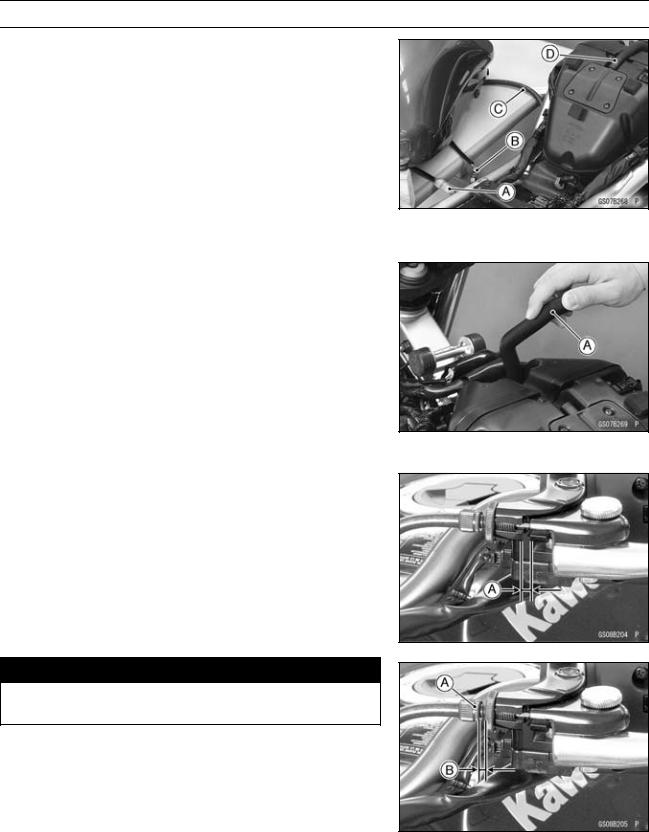
PERIODIC MAINTENANCE 2-25
Periodic Maintenance Procedures
Air Suction System Damage Inspection
•Remove:
Fuel Tank (see Fuel Tank Removal in the Fuel System (DFI) chapter)
Fuel Hose (see Fuel Hose Replacement)
•Connect the following parts temporary. Fuel Pump Lead Connector [A]
Fuel Level Sensor Lead Connector [B] Extension Tube [C]
Special Tool — Extension Tube: 57001-1578
•Pull the air switching valve hose [D] out of the air cleaner housing.
•Start the engine and run it at idle speed.
•Plug [A] the air switching valve hose end with your finger and feel vacuum pulsing in the hose.
 If there is no vacuum pulsation, check the hose line for leak. If there is no leak, check the air switching valve (see Air Switching Valve Unit Test in the Electrical System chapter) or air suction valve (see Air Suction Valve Inspection in the Engine Top End chapter).
Clutch
Clutch Operation Inspection
•Pull the clutch lever just enough to take up the free play [A].
•Measure the gap between the lever and the lever holder.  If the gap is too wide, the clutch may not release fully. If the gap is too narrow, the clutch may not engage fully. In either case, adjust it.
Clutch Lever Free Play
Standard: 2 3 mm (0.08 0.12 in.)

 WARNING
To avoid a serious burn, never touch the engine or exhaust pipe during clutch adjustment.
•Turn the adjuster [A] so that 5 6 mm (0.20 0.24 in.) [B] of threads are visible.

2-26 PERIODIC MAINTENANCE
Periodic Maintenance Procedures
•Open the clamp [A].
•Slide the dust cover [B] out of place.
•Loosen the locknut [C].
•Turn the adjusting nut [D] until the free play is correct.

 WARNING
Be sure that the outer cable end at the clutch lever is fully seated in the adjuster at the clutch lever, or it could slip into place later, creating enough cable play to prevent clutch disengagement.
•Tighten the locknut, and slip the dust cover back onto place.
•After the adjustment, start the engine and check that the clutch does not slip and that it releases properly.
Wheels/Tires
Air Pressure Inspection
•Remove the air valve cap.
•Measure the tire air pressure with an air pressure gauge [A] when the tires are cold (that is, when the motorcycle has not been ridden more than a mile during the past 3 hours).
•Install the air valve cap.
 Adjust the tire air pressure according to the specifications if necessary.
Air Pressure (when Cold)
Front: Up to 180 kg (397 lb)
225 kPa (2.25 kgf/cm², 32 psi)
|
Rear: |
Up to 180 kg (397 lb) |
|
250 kPa (2.50 kgf/cm²,36 psi) |
Wheel/Tire Damage Inspection
•Remove any imbedded stones [A] or other foreign particles [B] from tread.
•Visually inspect the tire for cracks and cuts, and replace the tire if necessary. Swelling or high spots indicate internal damage, requiring tire replacement.
•Visually inspect the wheel for cracks, cuts and dents damage.
 If any damage is found, replace the wheel if necessary.
Tire Tread Wear, Abnormal Wear Inspection
As the tire tread wears down, the tire becomes more susceptible to puncture and failure. An accepted estimate is that 90% of all tire failures occur during the last 10% of tread life (90% worn). So it is false economy and unsafe to use the tires until they are bald.
•Measure the tread depth at the center of the tread with a depth gauge [A]. Since the tire may wear unevenly, take measurement at several places.
 If any measurement is less than the service limit, replace the tire (see Tire Removal/Installation in the Wheels/Tires chapter).
Меню сайта
-
Мотообъявления
-
Мануалы скачать
-
Мануалы читать
-
Обратная связь
-
Гостевая книга
-
Мотоновости
-
Фотоальбом
-
Микрофиши
-
Мотостатьи
| Поиск по сайту |
| Категории раздела | ||||||||||||||||||
|
| Статистика |
|
Онлайн всего: 1 Онлайн гостей: 1 Онлайн пользователей: 0 |
| Наш опрос |
|
В поездке документы на Ваш мотоцикл находятся Дома В кармане В мотоцикле Нет документов [ Результаты · Архив опросов ] Всего ответов: 253 мануалы для:[ИЖ П] |
 |
 |
 |
Воскресенье, 24.09.2023, 16:58 Приветствую Вас Гость | RSS | Вход |
| Все мото здесь!!! | |||
|
| Главная » Файлы » KAWASAKI |
ER-6n
[  СКАЧАТЬ БЕСПЛАТНО МАНУАЛ ДЛЯ KAWASAKI ER-6n (6.76 Mb) СКАЧАТЬ БЕСПЛАТНО МАНУАЛ ДЛЯ KAWASAKI ER-6n (6.76 Mb)
] |
10.04.2016, 13:15 |
Название: Руководство по эксплуатации Kawasaki ER-6n 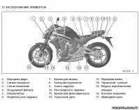 Автор: Производитель Формат: pdf Размер: 6,8 МБ Качество: Хорошее Язык: Русский Жанр: Мото-мануал Издательство: Напечатано в России Страниц: 163 Год издания: 2011 Описание: Руководство по обслуживанию и эксплуатации мотоцикла Кавасаки ER-6n на русском языке. |
|
Категория: KAWASAKI | Добавил: Talabas07 |
|
| Просмотров: 2228 | Загрузок: 365
| Рейтинг: 0.0/0 |
Похожие файлы:
- ZZR 600 (400)
- ER-6f
- KLX250
- Ninja 250R
- Ninja 300
- Ninja ZX-10R
- VERSYS1000
- Z750R
- Z800
- Z1000SX
- ZZ-R1100
- Kawasaki
| Всего комментариев: 0 | |
Войдите:
![]()
Dynojet POWER COMMANDER V Installation Instructions Manual (7 pages)
For kawasaki ninja 650r 2006; kawasaki ninja 650r 2007; kawasaki ninja 650r 2008; kawasaki ninja 650r 2009; kawasaki ninja 650r 2010; kawasaki ninja 650r 2011; kawasaki er-6n 2006; kawasaki er-6n 2007; kawasaki er-6n 2008; kawasaki er-6n 2009; kawasaki e
Brand:
Dynojet |
Category:
Motorcycle Accessories |
Size: 2.09 MB
-
Страница 1
ER-6n Motorcycle Service Manual http://mototh.com[…]
-
Страница 2
http://mototh.com[…]
-
Страница 3
This quick reference guide will assist you in locating a desired topic or pro- cedure. •Bend the pages back to match the black tab of the desired chapter num- ber with the black tab on the edge at each table of contents page. •Refer to the sectional table of contents for the exact pages to locate the spe- cific topic required. Quick Reference G[…]
-
Страница 4
http://mototh.com[…]
-
Страница 5
ER-6n Motorcycle Service Manual All rights reserved. No parts of this publication may be reproduced, stored in a retrieval system, or transmitted in any form or by any means, electronic mechanical photocopying, recording or otherwise, without the prior written permission of Quality Division/Consumer Products & Machinery Company/Kawasaki Heavy I[…]
-
Страница 6
LIST OF ABBREVIA TIONS A ampere(s) lb pound(s) ABDC after bottom dead center m meter(s) AC alternating current min minute(s) AT D C after top dead center N newton(s) BBDC before bottom dead center Pa pascal(s) BDC bottom dead center PS horsepower BTDC before top dead center psi pound(s) per square inch °C degree(s) Celsius r revolution DC direct c[…]
-
Страница 7
Foreword This manual is designed primarily for use by trained mechanics in a properly equipped shop. However , it contains enough detail and basic in- formation to make it useful to the owner who de- sires to perform his own basic maintenance and repair work. A basic knowledge of mechanics, the proper use of tools, and workshop proce- dures must be[…]
-
Страница 8
NOTE ○ This note symbol indicates points of par- ticular interest for more efficient and con — venient operation. • Indicates a procedural step or work to be done. ○ Indicates a procedural sub-step or how to do the work of the procedural step it follows. It also precedes the text of a NOTE. Indicates a conditional step or what action to take […]
-
Страница 9
GENERAL INFORMA TION 1-1 1 General Information T able of Contents Before Servicing …………………………………………………………………………………………………. ….. 1-2 Model Identification……………………………………………………………………………………………… ….. 1-7 Gener[…]
-
Страница 10
1-2 G ENERAL INFORMA TION Before Servicing Before starting to perform an inspection service or carry out a disassembly and reassembly opera- tion on a motorcycle, read the preca utions given below . T o facilitate ac tual operations, notes, illustra- tions, photographs, cautions, and detailed descriptions have been included in each chapter wherever[…]
-
Страница 11
GENERAL INFORMA TION 1-3 Before Servicing Arrangement and Cleaning of Removed Parts Disassembled parts are easy to confuse. Arrange the parts according to the order the parts were disassembled and clean the parts in order prior to assembly . Storage of Removed Parts After all the parts including subassembly parts have been cleaned, store the parts […]
-
Страница 12
1-4 G ENERAL INFORMA TION Before Servicing Tightening Sequence Generally , when installing a part with several bolts, nuts, or screws, start them all in their holes and tighten them to a snug fit. Then tighten them according to the specified se- quence to prevent case warpage or deformation which can lead to malfunction. Conversely when loosening t[…]
-
Страница 13
GENERAL INFORMA TION 1-5 Before Servicing Press For items s uch as bearin gs or oil seals that must be pressed into place, apply small amount of oil to the con- tact area. Be sure to maintain proper alignment and use smooth movements when installing. Ball Bearing and Nee dle Bearing Do not remove pressed ball or needle unless removal is absolutely […]
-
Страница 14
1-6 G ENERAL INFORMA TION Before Servicing Lubrication It is important to lubricate rotating or sliding parts during assembly to minimize wear during initial operation. Lubri- cation points are called out throughout this manual, apply the specific oil or grease as specified. Direction of Engine Rotation When rotating the crankshaft by hand, the fre[…]
-
Страница 15
GENERAL INFORMA TION 1-7 Model Identification ER650A6F/ ER650A6S Left Side Vi ew ER650A6F/ ER650A6S Right Side View ER650A6F: Australia, Malaysia ER650A6S: Europe http://mototh.com[…]
-
Страница 16
1-8 G ENERAL INFORMA TION General Specifications Items ER650A6F/ER650A6S Dimensions Overall Length 2 100 mm (82.7 in.) Overall Width 760 mm (29.9 in.) Overall Height 1 095 mm (43.1 in.) Wheelbase 1 405 mm (55.3 in.) Road Clearance 140 mm (5.5 in.) Seat Height 785 mm (30.9 in.) Dry M ass 174 kg (383.7 lb) Curb Mass: Front 98 kg (216.1 lb) Rear 98 kg[…]
-
Страница 17
GENERAL INFORMA TION 1-9 General Specifications Items ER650A6F/ER650A6S Vi scosity SAE 10W-40 Capacity 2 . 4L( 2 . 5U Sq t ) Drive T rain Primary Reduction System: Ty p e Gear Reduction Ratio 2.095 (88/42) Clutch T ype Wet multi disc T ransmission: Ty p e 6-speed, constant mesh, return shift Gear Ratios: 1st 2.438 (39/16) 2nd 1.714 (36/21) 3rd 1.33[…]
-
Страница 18
1-10 GENERAL INFORMA TION General Specifications Items ER650A6F/ER650A6S Headlight: Ty p e Semi-sealed beam Bulb 1 2V5 5W×2 / 5 5W( H i / L o ) T ail/Brake Light 12 V 5/21 W Alternator: Ty p e Three-phase AC Rated Output 24 A/14 V @5 000 r/min (rpm) Specifications are subject to change without notice, and may not apply to every country . http://mo[…]
-
Страница 19
GENERAL INFORMA TION 1-1 1 T echnical Informati on — Cassette T ype T ran smission Cassette T ype T ransmission The transmission of the current model is unable to be removed without disassembling upper and lower crankcase halves. The ER650A enables transmission to be removed from the right side of engine as an assy , without disassembling crankcase[…]
-
Страница 20
1-12 GENERAL INFORMA TION T echnical Information — Inlet Air Pressure Sensor Atmospheric pressure sensor and camshaft position sensor are not equipped with the ER650A. As a substitute of these sensors above, the ER650A recognizes atmospheric pressure and intake stroke of #1 by the signal of inlet air pressure sensor . The ECU detects atmospheric pr[…]
-
Страница 21
GENERAL INFORMA TION 1-13 Unit Conversio n T able Prefixes fo r Un its: Prefix Symbol Power mega M ×1 0 0 0 0 0 0 kilo k × 1 000 centi c ×0 . 0 1 milli m × 0.001 micro µ × 0.000001 Units of Mass: k g ×2 . 2 0 5 =l b g × 0.03527 = oz Units o f V olume: L × 0.2642 = gal (US) L × 0.2200 = gal (imp) L × 1.057 = qt (US) L × 0.8799 = qt (imp)[…]
-
Страница 22
http://mototh.com[…]
-
Страница 23
PERIODIC MAINTENANCE 2-1 2 Periodic Maintenance T able of Contents Periodic M aintenance Chart ………………………………………………………………………………. …….. 2-3 T orque and Locking Agent ………………………………………………………………………………………… 2-6 Specifications ..[…]
-
Страница 24
2-2 PERIODIC MAINTENANCE Steering P lay Inspection …………………………………………………………………………………… … 2-35 Steering P lay Adjustment…………………………………………………………………………………….. 2-35 Steering S tem B earing Lubrication ……………………….[…]
-
Страница 25
PERIODIC M AINTENANCE 2-3 Periodic Maintenance Chart The scheduled maintenance must be done in accordance with this chart to keep the motorcycle in good running condition. The initial maintenance is vitally important and must not be neglected. Periodic Inspection FREQUENCY Whichever comes first * ODOMETER READING × 1 000 km (× 1 000 mile) 1 6 12 […]
-
Страница 26
2-4 PERIODIC MAINTENANCE Periodic Main tenance Chart FREQUENCY Whichever comes first * ODOMETER READING ×10 0 0k m (× 1 000 mile) 1 6 12 18 24 30 36 INSPECTION Every (0.6) (4) (7.5) (12) (15) (20) (24) See Page Brake hose and pipe damage — inspect year • • • • • • • 2-31 Brake hose installation condition — inspect year • • • ?[…]
-
Страница 27
PERIODIC M AINTENANCE 2-5 Periodic Maintenance Chart Periodic Replacement Parts FREQUENCY Whichever comes first * ODOMETER READING × 1 000 km (× 1 000 mile) 1 12 24 36 48 CHANGE/REPLACE ITEM Every (0.6) (7.5) (15) (24) (30) See Page Air cleaner element # 2 years 2-45 Engine oil # year • • • • • 2-45 Oil filter year • • • • • 2[…]
-
Страница 28
2-6 PERIODIC MAINTENANCE T orque and Locking Agent The following tables list the tightening torque for the major fasteners requiring use of a non-permanent locking agent or liquid gasket. Letters used in the “Remarks” column mean: AL: T ighten the two clamp bolts alternately two times to ensure even tightening torque. EO: Apply engine oil. L: A[…]
-
Страница 29
PERIODIC MAINTENANCE 2-7 T orque and Locking Agent T orque Fastener N·m kgf·m ft·lb Remarks Clutch Upper Cap on Clutch Cover 3.9 0.40 35 in·lb Lower Cap on Clutch Cover – – – Hand-tighten Oil Filler Plug – – – Hand-tighten Clutch Cover Mounting Bolts 9.8 1.0 87 in·lb Clutch Spring Bolts 9.8 1.0 87 in·lb Clutch Hub Nut 132 13.5 98 […]
-
Страница 30
2-8 PERIODIC MAINTENANCE T orque and Locking Agent T orque Fastener N·m kgf·m ft·lb Remarks Oil Pressure Switch 15 1.5 11 SS Oil Passage Plug 20 2.0 15 L Gear Positioning Lever Bolt 12 1.2 106 in·lb L Shift Shaft Return Spring pin 29 2.9 22 L Shift Drum Cam Bolt 12 1.2 106 in·lb L Neutral Switch 15 1.5 11 T ransmission Case Bolts 20 2.0 15 Shi[…]
-
Страница 31
PERIODIC MAINTENANCE 2-9 T orque and Locking Agent T orque Fastener N·m kgf·m ft·lb Remarks Rear Shock Absorber Nut 59 6.0 44 Swingarm Pivot Shaft Nut 108 11 . 0 80 Steering Front Fork Clamp Bolts (Lower) 20 2.0 15 AL Front Fork Clamp Bolts (Upper) 20 2.0 15 Handlebar Holder Bolts 25 2.5 18 S Left Switch Housing Screws 3.5 0.36 31 in·lb Right S[…]
-
Страница 32
2-10 PERIODIC M AINTENANCE T orque and Locking Agent T orque Fastener N·m kgf·m ft·lb Remarks T iming Rotor Bolt 40 4.1 30 W ater T emperature Sensor 12 1.2 106 in·lb The table below , relating tightening torque to thread diameter , lists the basic torque for the bolts and nuts. Use this table for only the bolts and nuts w hich do not require a[…]
-
Страница 33
PERIODIC M AINTENANCE 2-1 1 Specifications Item Standard Service Limit Fuel System Throttle Grip Free Play 2 ∼ 3 mm (0.08 ∼ 0.12 in.) ––– Idle Speed 13 0 0± 5 0r / m i n( r p m ) ––– Bypass Screws (T urn Out) 0 ∼ 3 1/2 (for reference) ––– Engine V acuum 35.3 ±1.3 kPa (265 ±10 mm Hg) Air Cleaner Element Polyurethane Foam ?[…]
-
Страница 34
2-12 PERIODIC M AINTENANCE Specifications Item Standard Service Limit Final Drive Drive Chain Slack 30 ∼ 40 mm (1.2 ∼ 1.6 in.) ––– Drive Chain Wea r (20-link Length) 317.5 ∼ 318.2 mm (12.50 ∼ 12.53 in.) 323 mm (12.7 in.) Standard Chain: Make ENUMA ––– Ty p e EK520MVXL1 ––– Link 11 4 l i n k s ––– Brakes Brake Fluid: […]
-
Страница 35
PERIODIC M AINTENANCE 2-13 Special T ools Inside Circlip P l ie r s: 57001-143 Steering Stem Nut Wrenc h: 57001-1 100 Jack: 57001-1238 Oil Filter Wrench: 57001-1249 Extension T ube: 57001-1578 Pilot Screw Adjuster , E: 57001-1603 Jack Attachment: 57001-1608 http://mototh.com[…]
-
Страница 36
2-14 PERIODIC M AINTENANCE Periodic Maintenance Procedures Fuel System (DFI) Fuel Hose Inspection (fuel leak, damage, installatio n condition) ○ The fuel hose is designed to be used throughout the mo- torcycle’s life without any maintenance. However , if the motorcycle is not properly handled, the high pressure in- side the fuel line can cause […]
-
Страница 37
PERIODIC MAINTENANCE 2-15 Periodic Maintena nce Procedures If necessary , adjust the throttle c able as follows. • Loosen the locknut [A] at the upper end of the accelerator cable. • T urn the adjuster [B] in completely so as to give the throttle grip plenty of play . • Loosen the locknut [A] at the middle of the decelerator cable. • T urn […]
-
Страница 38
2-16 PERIODIC M AINTENANCE Periodic Maintenance Procedures Air Cleaner Element Cleaning NOTE ○ In dusty areas, the element should be cleaned more frequently than the recommended interval. ○ After riding through rain or on muddily roads, the ele- ment should be cleaned immediately . W ARNING If dirt or dust is allowed to pass through into the th[…]
-
Страница 39
PERIODIC MAINTENANCE 2-17 Periodic Maintena nce Procedures WA R N I N G Clean the element in a well-ventilated area, and make sure that there are no sparks or flame any- where near the working area. Because of the danger of highly flammable liquids, do not use gasoline or a low flash-point solvent to clean the element. • Clean the element [A] i n[…]
-
Страница 40
2-18 PERIODIC M AINTENANCE Periodic Maintenance Procedures • Start the engine and warm it up thoroughly . • Check the idle speed. T achometer [A] • Open and close the throttle. If the idle speed is out of the s pecified range, adjust it. CAUTION Do not measure the idle speed by the tachometer of the meter unit. • While idling the engine, in[…]
-
Страница 41
PERIODIC MAINTENANCE 2-19 Periodic Maintena nce Procedures • Repeat the same procedure for other bypass screws. • Repeat the synchronization. If the vacuums are correct, check the output voltage of the m ain throttle sensor (see Main Throttle Sensor Output V oltage Inspection in the Fuel System (DFI) chapter). Main Throttle Sensor Output V olta[…]
-
Страница 42
2-20 PERIODIC M AINTENANCE Periodic Maintenance Procedures Radiator Hose and Pipe Inspection (coolant leak, damage, installation condition) ○ The high pressure inside the radiator hose and pipe can cause coolant to leak [A] or the hose to burst if the line is not properly maintained. • Visually inspect the hoses for signs of deterioratio n. Squ[…]
-
Страница 43
PERIODIC MAINTENANCE 2-21 Periodic Maintena nce Procedures • Check the valve clearance when the pistons are at TDC. ○ The pistons are numbered beginning with the engine left side. • Using a wrench [A] on the crankshaft rotation bolt, turn the crankshaft clockwise until the «1|T» mark on the timing rotor is aligned with the notch [B][…]
-
Страница 44
2-22 PERIODIC M AINTENANCE Periodic Maintenance Procedures V alve C learance M easurin g Positi o n #2 Piston TDC at End of Compression Stroke → Inlet valve clearances of #2 piston, and Exhaust valve clearances of #2 piston If the v alve clearance is not with in the specified range, first record the clearance, and adjust it. V a lve Clearance Adj[…]
-
Страница 45
PERIODIC MAINTENANCE 2-23 Periodic Maintena nce Procedures V AL VE CLEARANCE ADJUSTMENT CHART INLET V A L V E 1. Measure the clearance (when engine is cold). 2. Check present shim size. 3. Match clearance in vertical column with present shim size in horizontal column. 4. Install the shim specified where the lines in tersect. This shim will give the[…]
-
Страница 46
2-24 PERIODIC M AINTENANCE Periodic Maintenance Procedures V AL VE CLEARANCE ADJU STMENT CHART EXHAU ST V A L VE 1. Measure the clearance (when engine is cold). 2. Check present shim size. 3. Match clearance in vertical column with present shim size in horizontal column. 4. Install the shim specified where the lines intersect. This shim w ill give […]
-
Страница 47
PERIODIC MAINTENANCE 2-25 Periodic Maintena nce Procedures Clutch Clutch Operation Inspection • Pull the c lutch lever just enough to take up the free play [A]. • Measure the gap between the lever and the lever holder . If the gap is too wide, the clutch may not release fully . If the gap is too narrow , the clutch may not engage fully . In eit[…]
-
Страница 48
2-26 PERIODIC M AINTENANCE Periodic Maintenance Procedures Wheel/Tire Damage In spection • Remove any imbedded stones [A] or other foreign parti- cles [B] from tread. • Visually inspect the tire for cracks and cuts, and replace the tire if necessary . Swelling or high spots indicate inter- nal damage, requiring tire replacement. • Visually in[…]
-
Страница 49
PERIODIC MAINTENANCE 2-27 Periodic Maintena nce Procedures Wheel Bearing Damage Inspection • Raise the front wheel off the ground with jack (see Front Wheel Removal in the Wheels/T ires chapter). • T urn the handlebar all the way to the right or left. • Inspect the roughness of the front wheel bearing by push- ing and pulling [A] the wheel. ?[…]
-
Страница 50
2-28 PERIODIC M AINTENANCE Periodic Maintenance Procedures • Apply oil to the sides of the rollers so that oil will penetrate to the rollers and bushings. Apply the oil to the O-rings so that the O-rings will be coated with oil. • Wipe off any excess oil. Oil Applied Areas [A] O-rings [B] Drive Chain Slack Inspection NOTE ○ Check the slack wi[…]
-
Страница 51
PERIODIC MAINTENANCE 2-29 Periodic Maintena nce Procedures • Insert a new cotter pin [A]. NOTE ○ When inserting the cotter pin, i f the slots in the nut do not align with the cotter pin hole in the axle, tighten the nut clockwise [B] up to next alignment. ○ It should be within 30°. ○ Loosen once and tighten again when the slot goes past th[…]
-
Страница 52
2-30 PERIODIC M AINTENANCE Periodic Maintenance Procedures Drive Chain W ear Inspection • Remove: Chain C over (see Swingarm R emoval in the S uspension chapter) • Rotate the rear wheel to inspect the drive chain for dam- aged rollers, and loose pins and links. If there is any irregularity , replace the drive chain. Lubricate the drive chain if[…]
-
Страница 53
PERIODIC MAINTENANCE 2-31 Periodic Maintena nce Procedures Brake System Brake Fluid Leak (Brake Hose and Pipe) Inspection • Apply the brake lever or pedal and inspect the brake fluid leak from the brake hoses [A] and fittings [B]. If the brake fluid leaked from any position, inspect or r e- place the problem part. Brake Hose Damage and Installati[…]
-
Страница 54
2-32 PERIODIC M AINTENANCE Periodic Maintenance Procedures Brake Fluid Level Inspection • Check that the brake fluid level in the front brake reservoir [A] is above the lower level line [B]. NOTE ○ Hold the reservoir horizontal by turning the handlebar when checking brake fluid level. If the fluid level is lower than the lower level line, fill […]
-
Страница 55
PERIODIC MAINTENANCE 2-33 Periodic Maintena nce Procedures Brake Pad Wear Inspection • Check the lining thickness [A] of the pads in each caliper . If the lining thickness of either pad is less than the service limit [B], replace both pads in the caliper as a set. Pad Lining Thickness Standard: Front 4.5 m m (0.18 in.) Rear 5.0 m m (0.20 in.) Ser[…]
-
Страница 56
2-34 PERIODIC M AINTENANCE Periodic Maintenance Procedures Suspensions Front Fo rks/Rear Shock Absorber Operation Inspection • Pump the forks down and up [A] 4 or 5 times, and inspect the smooth stroke. If the forks do not smoothly or noise is found, inspect the fork oil level or fork clamps (see Front Fork Oil Change in the Suspension chapter). […]
-
Страница 57
PERIODIC MAINTENANCE 2-35 Periodic Maintena nce Procedures Steering System Steering Play Inspection • Raise the front wheel off the ground with jack. Special T ools — Jack: 57001-1238 Jack Attachment: 57001-1608 • With the front wheel pointing straight ahead, alternately tap each end of the handlebar . The front wheel should swing fully left an[…]
-
Страница 58
2-36 PERIODIC M AINTENANCE Periodic Maintenance Procedures • Adjust the steering. Special T ool — Steering Stem N ut Wrench [A]: 57001-1 100 If the steering is too tight, loosen the stem nut [B] a fraction of a turn. If the steering is too loose, tighten the stem nut a fraction of a turn. NOTE ○ T urn the stem nut 1/8 turn at time maximum. • […]
-
Страница 59
PERIODIC MAINTENANCE 2-37 Periodic Maintena nce Procedures Electrical System Spark P lug Condition Inspectio n • Remove the spark plugs (see Spark Plug Replacement). • Visually inspect the spark plugs. If the spark plug center electrode [A] and/or side elec- trode [B] are corroded or damaged, or if the insulator [C] is cracked, replace the plug[…]
-
Страница 60
2-38 PERIODIC M AINTENANCE Periodic Maintenance Procedures Lights and Switches Operation I nspectio n First Step • T urn on the ignition switch. • The following lights should go on according to below table. City Light [A] goes on T aillig h t [B] goes on License Plate Light [C] goes on Meter Panel LCD [D] goes on Neutral Indicat or Light (LED) […]
-
Страница 61
PERIODIC MAINTENANCE 2-39 Periodic Maintena nce Procedures Third Step • T urn on the turn signal switch [A] (left or right position). • The left or right turn signal lights [B] (front and rear) ac- cording to the switch position should flash. • The turn signal indicator light (LED) [C] in the meter unit should flash. If the each light does no[…]
-
Страница 62
2-40 PERIODIC M AINTENANCE Periodic Maintenance Procedures • Set the dimmer switch to high beam position. • The low beam [A] and high beam [B] headlights should go on. • The high beam indicator light (LED) [C] should go on. If the high beam headlight and/or high beam indicator light (LED) does not go on, inspect or replace the following item.[…]
-
Страница 63
PERIODIC MAINTENANCE 2-41 Periodic Maintena nce Procedures NOTE ○ ON high beam, the brightest points should be slightly below horizontal with the motorcycle on its wheels and the rider seated. Adjust the headlight to the proper an- gle according to local regulations. Low Beam [A] Height of Headlight Center [B] High Beam [C] Sidestand Switch Opera[…]
-
Страница 64
2-42 PERIODIC M AINTENANCE Periodic Maintenance Procedures If the sidestand switch operation does not work, inspect or replace the following item. Battery (see Charging Condition Inspection in the Elec- trical System chapter) Main Fuse 30 A (see Fuse Inspection in the Electrical System chapter) Ignition Fuse 10 A (see Fuse Inspection in the Electri[…]
-
Страница 65
PERIODIC MAINTENANCE 2-43 Periodic Maintena nce Procedures Others Chassis Parts Lubrication • Before lubricating each part, clean off any rusty spots with rust remover and wipe off any grease, oil, dirt, or grime. • Lubricate the points listed below with indicated lubricant. NOTE ○ Whenever the vehicle has been operated under wet or rainy con[…]
-
Страница 66
2-44 PERIODIC M AINTENANCE Periodic Maintenance Procedures Bolts, Nuts and Fasteners Tightness Inspection • Check the tightness of the bolts and nuts listed here. Also, check to see that each cotter pin is in place and in good condition. NOTE ○ For the engine fasteners, check the tightness of them when the engine is cold (at room temperature). […]
-
Страница 67
PERIODIC MAINTENANCE 2-45 Periodic Maintena nce Procedures Replacement Parts Air Cleaner Element Replacement • Refer to the Air Cleaner Element Cleaning. Engine Oil Change • Situate the motorcycle so that it is vertical after warming up the engine. • Unscrew the oil filler plug [A]. • Place on oil pan beneath the engine. • Remove the engi[…]
-
Страница 68
2-46 PERIODIC M AINTENANCE Periodic Maintenance Procedures Oil Filter Replacement • Drain the engine oil (see Engine Oil C hange). • Remove the oil filter [A] with the oil filter wrench [B]. Special T ool — Oil Filter Wrench: 57001-1249 • Replace the filter with a new one. • Apply engine oil to the gasket [A] before installation. • T ight[…]
-
Страница 69
PERIODIC MAINTENANCE 2-47 Periodic Maintena nce Procedures • Install the new fuel hose. • Insert [A] the fuel hose joint [B] straight onto the delivery pipe until the hose joint clicks. • Push [C] the joint lock [D]. • Push and pull [A] the fuel hose joint [B] back and forth more than two times and make sure it is locked and doesn’t come […]
-
Страница 70
2-48 PERIODIC M AINTENANCE Periodic Maintenance Procedures • Put [A] the projection [B] on the reserve tank into the hole [C] on the frame bracket, and place the reserve tank on the right side of frame. • Place a container under the water pump drain bolt [A], then remove the drain bolt. • Remove the radiator cap [A] in two steps. First turn t[…]
-
Страница 71
PERIODIC MAINTENANCE 2-49 Periodic Maintena nce Procedures • When filling the coolant, choose a suitable mixture ratio by referring to the coolant manufacturer ’s directions. CAUTION Soft or distilled water must be used with the an- tifreeze in the cooling system. If hard water is used in the system, it causes scales accumulation in the water p[…]
-
Страница 72
2-50 PERIODIC M AINTENANCE Periodic Maintenance Procedures Radiator Hose and O-ring Replacement • Drain the coolant (see Coolant Change in the Periodic Maintenance chapter). • Remove: Thermostat Housing [A] (see W ater Pump Removal in the Cooling System chapter) W ater Pump Cover [B] (see W ater Pump Removal in the Cooling System chapter) Hoses[…]
-
Страница 73
PERIODIC MAINTENANCE 2-51 Periodic Maintena nce Procedures Brake Hose and Pipe Replacement CAUTION Brake fluid quickly ruins painted plastic surfaces; any spilled fluid should be completely washed away immediately . • Remove the banjo bolts [A]. • When removing the brake hose, take care not to spill the brake fluid on the painted or plastic par[…]
-
Страница 74
2-52 PERIODIC M AINTENANCE Periodic Maintenance Procedures • Level the brake fluid reservoir . • Remove the reservoir cap and diaphragm. • Remove the rubber cap from the bleed valve [A] on the caliper . • Attach a clear plastic hose [B] to the bleed valve, and run the other end of the hose into a container . • Fill the reservoir with fres[…]
-
Страница 75
PERIODIC MAINTENANCE 2-53 Periodic Maintena nce Procedures Master Cylinder Rubb er Parts Replacement Front Master Cylinder Disassembly • Remove the front master cylinder (see Front Master Cylin- der Removal in the Brakes chapter). • Remove the reservoir cap and diaphragm, and pour the brake fluid into a container . • Unscrew the locknut and p[…]
-
Страница 76
2-54 PERIODIC M AINTENANCE Periodic Maintenance Procedures • Apply brake fluid to the new parts and to the inner wall of the cylinder . • T ake care not to scratch the piston or the inner wall of the cylinder . • T ighten the brake lever pivot bolt and locknut. • Apply silicone grease. Brake Lever Pivot Bolt • T ighten: T orque — Brake Le[…]
-
Страница 77
PERIODIC MAINTENANCE 2-55 Periodic Maintena nce Procedures • Replace the fluid seals [A] with new ones. ○ Apply brake fluid to the fluid seals, and install them into the cylinders by hand. • Replace the dust s eals [B] with new ones if they are dam- aged. ○ Apply brake fluid to the dust seals, and install them into the cylinders by hand. ?[…]
-
Страница 78
2-56 PERIODIC M AINTENANCE Periodic Maintenance Procedures Rear Caliper Assembly • Clean the caliper parts except for the pads. CAUTION For cleaning of the parts, use only disc brake fluid, isopropyl alcohol, or ethyl alcohol. • Install the bleed valve and rubber cap. T orq ue — Bleed V alve: 7.8 N·m (0. 80 kgf· m, 6 9 in·lb ) • Replace th[…]
-
Страница 79
PERIODIC MAINTENANCE 2-57 Periodic Maintena nce Procedures • Insert the spark plug vertically into the plug hole with the spark plug installed in the plug wrench [A]. Owner ’ s T ool — Spark Plug Wrench , 16 mm: 921 10-1 132 • T ighten: T orque — Spark Plugs: 15 N·m (1.5 kgf·m, 1 1 ft·lb) • Install: Stick Coils (see Stick Coil (Ignition […]
-
Страница 80
http://mototh.com[…]
-
Страница 81
FUEL SYSTEM (DFI) 3-1 3 Fuel System (DFI) T able of Contents Exploded View …………………………………………………………………………………………………. …….. 3-4 DFI System ………………………………………………………………………………………………………. ……. 3-8 DFI Sys[…]
-
Страница 82
3-2 FUEL SYSTEM (DFI) Sensor Resistance Inspection ……………………………………………………………………………… 3-53 Crankshaft Sensor (Service Code 21) ………………………………………………………………………… 3-54 Crankshaft Sensor Removal/Installation ………………………………..[…]
-
Страница 83
FUEL SYSTEM (DFI) 3-3 Pump Screen, Fuel Filter Cleaning ……………………………………………………………………….. 3-86 Fuel Injectors …………………………………………………………………………………………………… …….. 3-88 Removal/Installation…………………………………..[…]
-
Страница 84
3-4 FUEL SYSTEM (DFI) Exploded View http://mototh.com[…]
-
Страница 85
FUEL SYSTEM (DFI) 3-5 Exploded View T orque No. Fastener N·m kgf· m ft·lb Remarks 1 Fuel Pump Bolts 9.8 1.0 87 in·lb L, S 2. FI Indicator LED Light 3. Throttle Cable (Accelerator) 4. Throttle Cable (Decelerator) 5. Throttle Body Assy 6. Injectors CL: Apply cable lubricant. EO: Apply engine oil. G: Apply grease. L: Apply a non-permanent locking […]
-
Страница 86
3-6 FUEL SYSTEM (DFI) Exploded View http://mototh.com[…]
-
Страница 87
FUEL SYSTEM (DFI) 3-7 Exploded View T orque No. Fastener N·m kgf·m ft·lb Remarks 1 W ater T emperature Sensor 12 1.2 106 in·lb 2 Speed Sensor Bolt 7.8 0.80 66 in·lb L 3 Oxygen Sensor (Europe Model) 44.1 4.50 32.5 4. Inlet Air Pressure Sensor 5. Air Switching V alve 6. Inlet Air T emperature Sensor 7. Crankshaft Sensor 8. Sealed Battery 9. Rela[…]
-
Страница 88
3-8 FUEL SYSTEM (DFI) DFI Sys tem DFI System http://mototh.com[…]
-
Страница 89
FUEL SYSTEM (DFI) 3-9 DFI System 1. Ignition Switch 2. Starter Lockout Switch 3. Starter Relay 4. T achometer 5. FI Indicator Light (LED) 6. Inlet Air Pressure Sensor 7. Spark Plug 8. Crankshaft Sensor 9. Injector 10. Main Throttle Sensor 1 1. Delivery Pipe 12. Subthrottle Sensor 13. Subthrottle V alve 14. Main Throttle V alve 15. Subthrottle V alv[…]
-
Страница 90
3-10 FUEL SYSTEM (DFI) DFI Sys tem DFI System Wiring Diagram http://mototh.com[…]
-
Страница 91
FUEL SYSTEM (DFI) 3-1 1 DFI System Part Name 1. Oxygen Sensor (Europe Model) 2. Crankshaft Sensor 3. Inlet Air T emperature Sensor 4. W ater T emperature Sensor 5. W ater-proof Joint E 6. Injectors 7. V ehicle-down Sensor 8. W ater-proof Joint D 9. Inlet Air Pressure Sensor 10. Main Throttle Sensor 1 1. Subthrottle Sensor 12. Subthrottle V alve Act[…]
-
Страница 92
3-12 FUEL SYSTEM (DFI) DFI Sys tem T erminal Names 1. Subthrottle V alve Actuator Drive Signal 2 2. Subthrottle V alve Actuator Drive Signal 1 3. W ater T emperature Warning Light Signal 4. Unused 5. Oxygen Sensor Signal 6. Speed Sensor Signal 7. Main Throttle Sensor Signal 8. Inlet Air Pressure Sensor Signal 9. Unused 10. Power Supply to Sensors 1[…]
-
Страница 93
FUEL SYSTEM (DFI) 3-13 DFI Parts Location DFI: Digital Fuel Injection Parts 1. FI Indicator Light LED (DFI) 2. Ignition Switch 3. Throttle Body Assy 4. Inlet A ir T emperature Sensor 5. Injectors 6. Fuel Pump 7. Relay Box (ECU Main Relay , Fuel Pump Relay , Radiator Fan Relay) 8. Fuse Box (ECU Fuse 15 A, Oxygen Sen- sor Heater Fuse 10 A) 9. ECU 10.[…]
-
Страница 94
3-14 FUEL SYSTEM (DFI) Specifications Item Standard Digital Fuel Injection System Idle Speed 1 300 ±50 r/min (rpm) Throttle Assy: Ty p e T wo barrel type Bore 38 mm (1.50 in.) ECU (Electronic Control Unit): Make Denso Ty p e Digital memory type, with built in IC igniter , sealed with resin Usable Engine Speed 100 ∼ 12 000 r/min (rpm) Fuel Pressu[…]
-
Страница 95
FUEL SYSTEM (DFI) 3-15 Specifications Item Standard Output V oltage with the sensor tilted 60 ∼ 70° or more: 0.65 ∼ 1.35 V with sensor arrow mark pointed up: 3.55 ∼ 4.45 V Subthrottle Sensor: Non-adjustable and non-removal Input V oltage 4.75 ∼ 5.25 V DC between BL and BR/BK leads Output V oltage at Idle Throttle Opening 0.4 ∼ 0.6 V DC b[…]
-
Страница 96
3-16 FUEL SYSTEM (DFI) Special T ools and Sealant Oil Pressure Gauge, 5 kgf/cm²: 57001-125 Fork Oil Level Gauge: 57001-1290 Hand T ester: 57001-1394 Throttle Sensor Setting Adapter #1: 57001-1400 Peak V oltage Adapter: 57001-1415 Needle Adapter Set: 57001-1457 Throttle Sensor Setting Adapter: 57001-1538 Sensor Harness Adapter: 57001-1561 Fuel Pres[…]
-
Страница 97
FUEL SYSTEM (DFI) 3-17 Special T ools and Sealant Kawasaki Bond (Silicone Sealant): 56019-120 http://mototh.com[…]
-
Страница 98
3-18 FUEL SYSTEM (DFI) DFI Servicing Precau tio ns DFI Servicing Precautions There are a number of important precautions that should be followed servicing the DFI system. ○ This DFI system is designed to be used with a 12 V sealed battery as its power source. Do not use any other battery except for a 12 V sealed battery as a power source. ○ Do […]
-
Страница 99
FUEL SYSTEM (DFI) 3-19 DFI Servicing Precautions ○ T o maintain the correct fuel/air mixture (F/A), there must be no inlet air leaks in the DFI system. Be sure to install the oil filler plug [A] after filling the engine oil. Clutch C over [B] T orque — O il Filler Plug: Hand-tighten http://mototh.com[…]
-
Страница 100
3-20 FUEL SYSTEM (DFI) T roubleshooti ng the DFI S ystem Outline Outline When an abnormality in the system occurs, the FI indica- tor LED (Light Emitting Diode) light goes on to alert the rider on the meter panel. In addition, the condition of the problem is stored in the memory of the ECU (electronic control unit). With the engine stopped and turn[…]
-
Страница 101
FUEL SYSTEM (DFI) 3-21 T roubleshooting the DFI System ○ The DFI part connectors [A] have seals [B], including the ECU. • Join the connector and insert the needle adapters [C] inside the seals [B] from behind the connector until the adapter reaches the terminal. Special T ool — Needle Adapter Set: 57001-1457 CAUTION Insert the needle adapter st[…]
-
Страница 102
3-22 FUEL SYSTEM (DFI) T roubleshooti ng the DFI S ystem • Pull each connector [A] apart and inspect it for corrosion, dirt, and damage. If the c onnector i s corroded or dirty , clean it carefully . If it is damaged, replace it. Connect the connectors securely . • Check the wiring for continuity . ○ Use the wiring diagram to find the ends of[…]
-
Страница 103
FUEL SYSTEM (DFI) 3-23 T roubleshooting the DFI System ○ There are two ways to inspect the DFI system. One is voltage Check Method and the other is Resistance Check Method. (V oltage Check Method) ○ This method is conducted by measuring the input voltage [B] to a sensor [A] first, and then the output voltage [C] from the sensor . ○ Sometimes […]
-
Страница 104
3-24 FUEL SYSTEM (DFI) T roubleshooti ng the DFI S ystem DFI Diagnosis Flow Chart Inquiries to Rider Inquiries to Rider ○ Each rider reacts to problems in different ways, so it is important to confirm what kind of symptoms the rider has encountered. ○ T ry to find out exactly what problem occurred under exactly what conditions by asking the rid[…]
-
Страница 105
FUEL SYSTEM (DFI) 3-25 T roubleshooting the DFI System Sample Diagnosis Sheet Rider name: Registration No. (license plate No.): Y ear of initial registration: Model: Engine No.: Frame No.: Date problem occurred: Mileage: Environment when problem occurred. Weather □ fine, □ cloudy , □ rain, □ snow , □ always, □ other: T emperature □ ho[…]
-
Страница 106
3-26 FUEL SYSTEM (DFI) T roubleshooti ng the DFI S ystem □ clutch slipping □ other □ spark plug loose (tighten it) □ spark plug dirty , broken, or gap maladjusted (remedy it) Poor running or no power at high speed □ spark plug incorrect (replace it) □ knocking (fuel poor quality or incorrect, → use high-octane gasoline) □ brake drag[…]
-
Страница 107
FUEL SYSTEM (DFI) 3-27 DFI System T roubleshooting Guide NOTE ○ This is not an exhaustive list, giving every possi ble cause for each problem listed. It is meant simply as a rough guide to assist the troubleshooting for some of the more common difficulties. ○ The ECU may be involved in the DFI electrical and ignition system troubles. If these p[…]
-
Страница 108
3-28 FUEL SYSTEM (DFI) DFI System T roubleshooting Guide Symptoms or possible Causes Actions (chapter) Clutch lever not pulled in and gear not in neutral whether sidestand up or not Pull the lever in and shift the gear in neutral. Though clutch lever pulled in, sidestand up and gear not in neutral Sidestand down and clutch lever pulled in whether g[…]
-
Страница 109
FUEL SYSTEM (DFI) 3-29 DFI System T roubleshooting Guide Symptoms or possible Causes Actions (chapter) No valve clearance Adjust (see chapter 2). V alve guide worn Inspect and replace (see chapter 5). V alve spring broken or weak Inspect and replace (see chapter 5). V alve not seating properly (valve bent, worn or carbon accumulating on seating sur[…]
-
Страница 110
3-30 FUEL SYSTEM (DFI) DFI System T roubleshooting Guide Symptoms or Possible Causes Actions (chapter) Engine stalls easily: Fuel pump trouble Inspect (see chapter 3). Fuel injector trouble Inspect (see chapter 3). Main throttle sensor trouble Inspect (see chapter 3). Fuel pressure too low or too high Inspect (see chapter 3). Inlet air pressure sen[…]
-
Страница 111
FUEL SYSTEM (DFI) 3-31 DFI System T roubleshooting Guide Symptoms or Possible Causes Actions (chapter) Loose terminal of battery (–) lead or engine ground lead Inspect and repair (see chapter 16). Delay of ignition timing Inspect crankshaft sensor and IC igniter in ECU (see chapter 16). Poor acceleration: T oo low fuel pressure Inspect (see chapt[…]
-
Страница 112
3-32 FUEL SYSTEM (DFI) DFI System T roubleshooting Guide Symptoms or Possible Causes Actions (chapter) Inlet air temperature sensor trouble Inspect (see chapter 3). W ater temperature sensor trouble Inspect (see chapter 3). Inlet air pressure sensor trouble Inspect (see chapter 3). Fuel injector trouble Inspect (see chapter 3). Run-on (dieseling): […]
-
Страница 113
FUEL SYSTEM (DFI) 3-33 DFI System T roubleshooting Guide Symptoms or Possible Causes Actions (chapter) Throttle body assy O-ring damaged Replace (see chapter 3). Fuel tank air vent obstructed Inspect and repair (see chapter 3). Fuel line clogged Inspect and repair (see chapter 3). Fuel pump operates intermittently and often DFI fuse blows. Pump bea[…]
-
Страница 114
3-34 FUEL SYSTEM (DFI) DFI System T roubleshooting Guide Symptoms or Possible Causes Actions (chapter) Drive train trouble Inspect drive chain (see chapter 2) and sprockets (see chapter 1 1). Camshaft cam worn Inspect and replace (see chapter 5). Air switching valve trouble Inspect and replace (see chapter 5). Air suction valve trouble Inspect and […]
-
Страница 115
FUEL SYSTEM (DFI) 3-35 Self-Diagnosis Self-diagnosis Outline Self-diagnosis Outlin e The self-diagnosis system has three modes and can be switched to another mode by grounding the self-diagnosis terminal. User Mode The ECU notifies the rider of troubles in DFI system and ignition system by lighting the FI indicator when DFI system and ignition syst[…]
-
Страница 116
3-36 FUEL SYSTEM (DFI) Self-Diagnosis • T o enter the s elf-diagnosis dealer mode 2, open [B] and ground [A] the lead more than five times [F] within 2 sec- onds [C] after the lead is first grounded, and then keep it grounded continuously [D] for more than 2 seconds. ○ Count the blinks of the light (LED) to read the service code. Keep the auxil[…]
-
Страница 117
FUEL SYSTEM (DFI) 3-37 Self-Diagnosis http://mototh.com[…]
-
Страница 118
3-38 FUEL SYSTEM (DFI) Self-Diagnosis H o wt oR e a dS e r v i c eC o d e s How to Read Service Codes ○ Service codes are shown by a series of long and short blinks of the FI indicator light (LED) as shown below . ○ Read 10th digit and unit digit as the FI indicator light (LED) blinks. ○ When there are a number of problems, all the service co[…]
-
Страница 119
FUEL SYSTEM (DFI) 3-39 Self-Diagnosis S e r v i c eC o d eT a b l e Service Code T able Service Code FI Indicator LED Light Problems 11 Main throttle sensor malfunction, wiring open or short 12 Inlet air pressure sensor malfunction, wiring open or short 13 Inlet air temperature sensor malfunction, wiring open or short 14 W ater temperature sensor m[…]
-
Страница 120
3-40 FUEL SYSTEM (DFI) Self-Diagnosis Backups Backups ○ The ECU takes the following measures to prev ent engine damage w hen the DFI or the ignition system parts have troubles. Service Codes Parts Output Signal Usable Range or Criteria Backups by ECU 11 Main Throttle Sensor Main Throttle Sensor Output V oltage 0.20 ∼ 4.8 V If the m ain throttle[…]
-
Страница 121
FUEL SYSTEM (DFI) 3-41 Self-Diagnosis Service Codes Parts Output Signal Usable Range or Criteria Backups by ECU 51 Stick Coil #1 (Ignition Coil)* The stick coil primary winding must send signals (output voltage) continuously to the ECU. If the ignition primary winding #1 has failures (no signal, wiring short or open), the ECU shuts of f the injecto[…]
-
Страница 122
3-42 FUEL SYSTEM (DFI) Main Throttle Sensor (Service Code 1 1) Main Throttle Sensor Removal/Adj ustment CAUTION Do not remove or adjust the main throttle sensor [A] since it has been adjusted and set with precision at the factory . Never drop the sensor , especially on a hard surface. Such a shock to the sensor can damage it. Input V oltage Insp ec[…]
-
Страница 123
FUEL SYSTEM (DFI) 3-43 Main Throttle Sensor (Service Code 1 1) Output V oltage Inspection • Measure the output voltage at the m ain throttle sensor in the same way as input voltage inspection, Note the following. • Disconnect the main throttle sensor connector and con- nect the harness adapter [A] between these connectors. Special T ool — Throt[…]
-
Страница 124
3-44 FUEL SYSTEM (DFI) Main Throttle Sensor (Service Code 1 1) Resistance Inspection • T urn the ignition switch OFF . • Disconnect the main throttle sensor connector . • Connect a digital m eter [A] to the main throttle sensor connector [B]. • Measure the main throttle sensor resistance. Main Throttle Sensor Resistance Connections: BL lead[…]
-
Страница 125
FUEL SYSTEM (DFI) 3-45 Inlet Air Pressure Sensor (Service Code 12) CAUTION Never drop the sensor , especially on a hard surface. Such a shock to the part can damage it. Removal • Remove: Left C enter Fairing (see Center Fairing Removal in the Frame c hapter) • Disconnect the inlet air pressure sensor connector [A] and the vacuum hose [B]. • P[…]
-
Страница 126
3-46 FUEL SYSTEM (DFI) Inlet Air Pressure Sens or (Service Code 12) Output V oltage Inspection NOTE ○ The output voltage changes according to the local at- mospheric pressure. • Measure the output voltage at the ECU in the same way as input voltage inspection. Note the following. Inlet Air Pressure Sensor Out put V o lt ag e Connections to ECU […]
-
Страница 127
FUEL SYSTEM (DFI) 3-47 Inlet Air Pressure Sensor (Service Code 12) then Pv = Pl – Pg For example, suppose the following data is obtained: Pg = 8 cmHg (V acuum gauge reading) Pl = 70 cmHg (V arometer r eading) Vv = 3.2 V (Digital volt meter reading) then Pv = 70 – 8 = 62 cmHg (Abs) Plot this Pv (62 cmHg) at a point [1] on the chart and draw a ve[…]
-
Страница 128
3-48 FUEL SYSTEM (DFI) Inlet Air Pressure Sens or (Service Code 12) Pv = 55 ∼ 86 cmHg Vv: Inlet Air Pressure Sensor Output V oltage (V) (Digital Meter Reading) Pv: Throttle V acuum Pressure (Absolute) Ps: Standard Atmospheric Pressure (Absolute) ID: Idling TO: Throttle Full Open ST : Standard of Sensor Output V oltage (v) UR: Usable Range of Sens[…]
-
Страница 129
FUEL SYSTEM (DFI) 3-49 Inlet Air Pressure Sensor (Service Code 12) Inlet Air Pressure Sensor Circuit 1. ECU 2. W ater-proof Joint E 3. W ater-proof Joint D 4. Inlet Air Pressure Sensor http://mototh.com[…]
-
Страница 130
3-50 FUEL SYSTEM (DFI) Inlet Air T emperature Sensor (Service Code 13) Removal/Installation CAUTION Never drop the sensor , especially on a hard surface. Such a shock to the sensor can damage it. • Remove the fuel tank (see Fuel T ank Removal). • Disconnect the connector [A] from the inlet air tempera- ture sensor . • Remove the screw [B]. ?[…]
-
Страница 131
FUEL SYSTEM (DFI) 3-51 Inlet Air T emperature Sensor (Service Code 13) Sensor Resistance I nspectio n • Remove the inlet air temperature sensor . • Suspend the sensor [A] in a container of machine oil so that the heat-sensitive portion is submerged. • Suspend a thermometer [B] with the heat-sensitive por- tion [C] located in almost the same d[…]
-
Страница 132
3-52 FUEL SYSTEM (DFI) W ater T emperature Sensor (Service Code 14) Water T emperature Sensor Removal/Installation CAUTION Never drop the sensor , especially on a hard surface. Such a shock to the sensor can damage it. • Drain the coolant (see Coolant Change in the Periodic Maintenance chapter). • Disconnect the sensor connector [A], and unscre[…]
-
Страница 133
FUEL SYSTEM (DFI) 3-53 W ater T emperature Sensor (Service Code 14) W ater T emperatu re Sensor Circuit 1. ECU 2. W ater T emperature Sensor 3. W ater-proof Joint E 4. Meter Unit Sensor Resistance I nspectio n • Remove the water temperature sensor (see W ater T em- perature Sensor Removal/Installation). • Refer to W ater T emperature Sensor Ins[…]
-
Страница 134
3-54 FUEL SYSTEM (DFI) Crankshaft Sensor (Service Code 21) Start the engine and switch the diagnosis mode to Dealer 1 mode to know all the problem that the DFI system has at the time of self-diagnosis. If the engine cannot be started, the self-diagnosis system does not detect dynamic condi- tion of the crankshaft sensor . In this case, turn off the[…]
-
Страница 135
FUEL SYSTEM (DFI) 3-55 Speed Sensor (Service C ode 24, 25) Speed Sensor Removal/Installation • See the Switches and Sensors section in the Electrical System chapter . Speed Sensor Inspection • See Speed Sensor Inspection section in the Electrical System chapter . Speed Sensor Input V oltage Insp ection NOTE ○ Be sure the battery is fully char[…]
-
Страница 136
3-56 FUEL SYSTEM (DFI) Speed Sensor (Service Code 24, 25) • Disconnect the speed sensor connector and connect the harness adapter [A] between the harness connector and speed sensor connector . • Connect a digital meter to the harness adapter leads. Special T ool — Throttle Sensor Sett ing Adapter #1: 57001 -1400 • Measure the sensor output vo[…]
-
Страница 137
FUEL SYSTEM (DFI) 3-57 V e hicle- down Sensor (Service Co de 31) V ehicle-down Sensor Removal CAUTION Never drop the down-sensor , especially on a hard surface. Such a shock to the sensor can damage it. • Remove: Bolts [A] Connection and V ehicle-down Sensor [B] V ehicle-down Sensor Installation • The UP mark [A] of the sensor should face upwar[…]
-
Страница 138
3-58 FUEL SYSTEM (DFI) V ehicle-down Sensor (Service Code 31) • Remove the sensor . • Connect a digital volt meter [A] to the connector with nee- dle a dapter set [B]. Special T ool — Needle Adapter Set: 57001-1457 V ehicle-down Sensor Output V oltage Connections to Sensor Meter (+) → Y/G lead [E] Meter (–) → BR/BK lead [F] • Hold the s[…]
-
Страница 139
FUEL SYSTEM (DFI) 3-59 V e hicle- down Sensor (Service Co de 31) V ehicle-down Sensor Circuit 1. ECU 2. W ater-proof Joint E 3. V ehicle-down Sensor 4. W ater-proof Joint D http://mototh.com[…]
-
Страница 140
3-60 FUEL SYSTEM (DFI) Subthrottle Sensor ( Service Code 32) Subthrottle Sensor Removal/Adjustment CAUTION Do not remove or adjust the subthrottle sensor [A] since it has been adjusted and set with precision at the factory . Never drop the sensor , especially on a hard surface. Such a shock to the sensor can damage it. Subthrottle Sensor Input V ol[…]
-
Страница 141
FUEL SYSTEM (DFI) 3-61 Subthrottle Sensor (Service Code 32) Subthrottle Sensor O utput V oltage Insp ection • Remove the fuel tank (see Fuel T ank Removal). • Measure the output voltage at the subthrottle sensor in the same way as input voltage inspection. Note the fol- lowing. • Disconnect the subthrottle sensor connector and (black) connect[…]
-
Страница 142
3-62 FUEL SYSTEM (DFI) Subthrottle Sensor ( Service Code 32) Subthrottle Sensor Resistance Inspection • T urn the ignition switch OFF . • Disconnect the subthrottle sensor connector . • Connect a digital meter [A] to the subthrottle sensor con- nector [B]. • Measure the subthrottle sensor resistance. Throttle Sensor Resistance Connections: […]
-
Страница 143
FUEL SYSTEM (DFI) 3-63 Oxygen Sensor-not activated (S ervice Code 33) — Europe Model Oxygen Se nsor Remo val/In stallation • Refer to Switches and Sensors section in the Electrical System chapter . Oxygen Sensor Inspection • W arm up the engine thoroughly until the radiator fan starts. • T urn the ignition switch OFF . • Remove: Left C ente[…]
-
Страница 144
3-64 FUEL SYSTEM (DFI) Oxygen Sensor-not activated (S ervi ce Code 33) — Euro pe Model • Measure the output voltage of the sensor with the con- nector joined. Oxygen Sensor Output V oltage (without Plugs) Standard: 0.2 V or less If the reading is within range (with plugs: 0.7 V or more, without plugs: 0.2 V or less), the oxygen sensor is good. If[…]
-
Страница 145
FUEL SYSTEM (DFI) 3-65 Stick Coils (#1, #2: Service Code 51, 52) Stick Coil #1: Ignition Coil (Service Code 51) Stick Coil #2: Ignition Coil (Service Code 52) Stick Coil Removal/Installation CAUTION Never drop the stick coils, especially on a hard sur- face. Such a shock to the stick coil can damage it. • Refer to the Ignition System section in t[…]
-
Страница 146
3-66 FUEL SYSTEM (DFI) Stick Coils (#1, #2: Service Code 51, 52) Stick Coil Circuit 1. ECU 2. W ater-proof Joint C 3. Stick Coils 4. Engine Stop Switch 5. Ignition Switch 6. Ignition Fuse 10 A 7. Main Fuse 30 A 8. Battery 9. Frame Ground 10. Joint Connector http://mototh.com[…]
-
Страница 147
FUEL SYSTEM (DFI) 3-67 Radiator Fan Relay (Service Code 56) Radiator Fan Relay Removal/Installation • Radiator fan relay is bult in the relay box. • Remove the relay box (see Relay Box Removal in the Electrical System chapter). Radiator Fan Relay Inspection • See Relay Circuit Inspection in the Electrical System chapter . • Remove the relay[…]
-
Страница 148
3-68 FUEL SYSTEM (DFI) Subthrottle V alve Actuator (Service Code 62) Subthrottle Valve Actuator Remo val CAUTION Do not remove the subthrottle valve actuator [A] since it has been adjusted and set with precision at the factory . Never drop the actuator , especially on a hard sur- face. Such a shock to the actuator can damage it. Subthrottle V alve […]
-
Страница 149
FUEL SYSTEM (DFI) 3-69 Subthrottle V alve Actuator (Service Code 62) Subthrottle V alve Actuator Input Voltage Inspection NOTE ○ Be sure the battery is fully charged. • T urn the ignition switch OFF . • Connect the peak voltage adapter [A] and a digital meter [B] to the connector [C], using the needle adapter set [D]. Special T ools — Peak V […]
-
Страница 150
3-70 FUEL SYSTEM (DFI) Air Switching V alve (Service Code 64) Air Switching V alve R emoval/Insta llation • Refer to Clean Air System section in the Engine T op End chapter . Air Switching Valve Inspection • Refer to Air Switching V alve section in the Electrical Sys- tem chapter . • Remove the fuel tank and check the wiring continuity , us- […]
-
Страница 151
FUEL SYSTEM (DFI) 3-71 Oxygen Sensor Heater (Servi ce Code 67) — Europe Model Oxygen Sensor Hea ter Removal/Installation The oxygen sensor heater is bult in the oxygen sensor . So, the heater itself can not be removed. Remove the oxy- gen sensor (see Oxygen Sensor Removal in the Electrical System chapter). Oxygen Sensor Heater Inspection • Remove[…]
-
Страница 152
3-72 FUEL SYSTEM (DFI) Oxygen Sensor Heater (Servi ce Code 67) — Europe Model Oxygen Sensor Circuit 1. ECU 2. Oxygen Sensor 3. W ater-proof Joint E 4. W ater-proof Joint D 5. Oxygen Sensor Heater Fuse 10 A 6. Main Fuse 30 A 7. Battery 8. Frame Ground 9. Joint Connector http://mototh.com[…]
-
Страница 153
FUEL SYSTEM (DFI) 3-73 Oxygen Sensor-Incorrect Output V olta ge (Service Code 94) — Europe Model Oxygen Se nsor Remo val/In stallation • Refer to Oxygen Sensor Removal/Installation in the Elec- trical System chapter . Oxygen Sensor Inspection • W arm up the engine thoroughly until the radiator fan starts. • T urn the ignition switch OFF . •[…]
-
Страница 154
3-74 FUEL SYSTEM (DFI) Oxygen Sensor-Incorrect Output V ol tage (Service Code 94) — Europe Model • Measure the output voltage of the sensor with the con- nector joined. Oxygen Sensor Output V oltage (without Plugs) Standard: 0.2 V or less If the reading is within range (with plugs: 0.7 V or more, without plugs: 0.2 V or less), the oxygen sensor i[…]
-
Страница 155
FUEL SYSTEM (DFI) 3-75 FI Indicator Light (LED) Inspection Flow Chart http://mototh.com[…]
-
Страница 156
3-76 FUEL SYSTEM (DFI) FI Indicator Light (LED) FI Indica tor Light (LED) Inspection • Remove the m eter unit (see Meter Unit Removal i n the Electrical System chapter). • Using two auxiliary leads, supply battery power to the FI indicator light (LED) [A]. 12 V Battery [B] FI Indicator Light (LED) Check Connector: Meter Connector [C] (disconnec[…]
-
Страница 157
FUEL SYSTEM (DFI) 3-77 ECU CAUTION Never drop the ECU, especially on a hard surface. Such a shock to the ECU can damage it. ECU Removal • Remove: Seat (see Seat Removal in the Frame chapter) Grab Rails [A] (see Seat Covers Removal in the Frame chapter) Center Seat Cover [B] (see Seat Covers section in the Frame c hapter) Seat Covers [C] (see Seat[…]
-
Страница 158
3-78 FUEL SYSTEM (DFI) ECU ECU Power Su pply Inspection • Visually inspect the terminals [A] of the ECU connectors. If the connector is clogged with mud or dust, blow it off with compressed air . Replace the main harness if the terminals of the main harness connectors are cracked, bent, or otherwise dam- aged. Replace the ECU if the terminals of […]
-
Страница 159
FUEL SYSTEM (DFI) 3-79 ECU ECU Power Source Circuit 1. ECU 2. W ater-proof Joint C 3. Ignition Switch 4. W ater-proof Joint A 5. ECU Main Fuse 15 A 6. ECU Main Relay 7. Relay Box 8. Main Fuse 30 A 9. Battery 10. Frame Ground 1 1. Joint Connector http://mototh.com[…]
-
Страница 160
3-80 FUEL SYSTEM (DFI) Fuel Line Fuel Pressure Inspection NOTE ○ This inspection can determine which trouble the DFI system has, mechanical or electrical trouble. ○ It is preferable to measure the fuel pressure while run- ning the motorcycle just when trouble occurred in order to know symptom well. ○ Be sure the battery is fully charged. • […]
-
Страница 161
FUEL SYSTEM (DFI) 3-81 Fuel Line • T urn the ignition switch ON. The fuel pump will turn for 3 seconds, and then stop. CAUTION Do not drive the fuel pump without the fuel in the fuel tank. • Measure the fuel pressure with the engine stopped. Fuel Pressure Right after Ignition Switch ON, with pump running: Standard: 323 kPa (3.3 kgf/cm², 47 psi[…]
-
Страница 162
3-82 FUEL SYSTEM (DFI) Fuel Line Fuel Flow Rate Inspection NOTE ○ Be sure the battery is fully charged. W ARNING Gasoline is extremely flammable and can be explo- sive under certain conditions. Make sure the area is well-ventilated and free from any source of flame or sparks; this includes any appliance with a pilot light. Do not smoke. T urn the[…]
-
Страница 163
FUEL SYSTEM (DFI) 3-83 Fuel Line CAUTION Do not drive the fuel pump without the fuel in the fuel tank. • Measure the discharge for 3 seconds with the plastic hose filled with fuel. ○ Repeat this operation several times. Amount of Fuel Flow Standard: 60 mL or more for 3 seconds If the fuel flow is much less than the specified, check the battery […]
-
Страница 164
3-84 FUEL SYSTEM (DFI) Fuel Pump Fuel Pump Removal CAUTION Never drop the fuel pump, especially on a hard sur- face. Such a shock to the pump can damage it. W ARNING Gasoline is extremely flammable and can be explo- sive under certain conditions. Make sure the area is well-ventilated and free from any source of flame or sparks; this includes any ap[…]
-
Страница 165
FUEL SYSTEM (DFI) 3-85 Fuel Pump • Replace the fuel pump gasket [A] with a new one. • Apply a non-permanent locking agent to the threads of the fuel pump bolts. • T ighten the fuel pump bolts to a snug fit, tighten them alternating diagonally . T orque — Fuel Pump Bolts: 9.8 N·m (1.0 kgf·m, 87 in·lb) • T ighten the pump bolts again alter[…]
-
Страница 166
3-86 FUEL SYSTEM (DFI) Fuel Pump • Connect the hand tester (25 V DC) to the fuel pump con- nector [A] with needle adapter set. Special T ools — Hand T ester: 57001-1394 Needle Adapter Set: 57001-1457 ○ Measure the operating voltage with the engine stopped, and with the connector joined. • T urn the ignition switch ON. ○ The tester needle sh[…]
-
Страница 167
FUEL SYSTEM (DFI) 3-87 Fuel Pump Fuel Pump Circuit 1. ECU 2. W ater-proof Joint C 3. Engine Stop Switch 4. Ignition Switch 5. Ignition Fuse 10 A 6. Fuel Pump Relay 7. Relay Box 8. Main Fuse 30 A 9. Battery 10. Frame Ground 1 1. Fuel Pump http://mototh.com[…]
-
Страница 168
3-88 FUEL SYSTEM (DFI) Fuel Injectors Removal/Installation • Refer to the Throttle Body Assy Disassembly/Assembly . Audible Inspection • Start the engine. • Apply the tip of a screwdriver [A] to the injector [C]. Put the grip end onto your ear , and listen whether the injector is clicking or not. ○ A sound scope [B] can also be used. • Do[…]
-
Страница 169
FUEL SYSTEM (DFI) 3-89 Fuel Injectors Fuel Inje ctor Output Voltage Inspection • T urn the ignition switch OFF . • Remove the ECU (see ECU Power Supply Inspection). • Connect a digital voltmeter [A] to the ECU connector [B] with the needle adapter set [C]. Special T ool — Needle Adapter Set: 57001-1457 Injector Output V oltage Connections to […]
-
Страница 170
3-90 FUEL SYSTEM (DFI) Fuel Injectors • Remove the fuel tank (see Fuel T ank Removal). • Remove the air cleaner housing ( see Air Cleaner Housing Removal) • Remove connectors for injector [A]. • Connect each test light set [B] to the injector sub harness connector [C]. • T urn the ignition switch ON. • While cranking the engine with the[…]
-
Страница 171
FUEL SYSTEM (DFI) 3-91 Fuel Injectors Injector Unit T est • Use two leads [A] and the same test light set [B] as in “Injector Signal T est”. Rating of Bulb [C]: 12 V × (3 ∼ 3.4) W 12 V Battery [D] CAUTION Be sure to connect the bulb in series. The bulb works as a current limiter to protect the solenoid in the injector from excessive curren[…]
-
Страница 172
3-92 FUEL SYSTEM (DFI) Fuel Injectors Fuel Injector Circuit 1. ECU 2. Fuel Injectors 3. W ater-proof Joint C 4. Engine Stop Switch 5. Ignition Switch 6. Ignition Fuse 10 A 7. Fuel Pump Relay (for fuel pump and injec- tors) 8. Relay Box 9. Main Fuse 30 A 10. Battery 1 1. Frame Ground 12. Joint Connector http://mototh.com[…]
-
Страница 173
FUEL SYSTEM (DFI) 3-93 Throttle Grip a nd Cables Throttle Grip F ree Play Inspection • Refer to Throttle Control System Inspection in the Peri- odic Maintenance c hapter . Throttle Grip Free Play Adjustment • Refer to Throttle Control System Inspection in the Peri- odic Maintenance c hapter . Throttle Cable Installation • Install the throttle[…]
-
Страница 174
3-94 FUEL SYSTEM (DFI) Throttle Body Assy Idle Speed Inspection • Refer to Idle Speed Inspection in the Periodic Mainte- nance c hapter . Engine V acuum Synchronization Inspection/Adjust- ment • Refer to Engine V acuum Synchronization Inspection in the Periodic Maintenance chapter . High Altitude Performance Adju s tment • Any modification is[…]
-
Страница 175
FUEL SYSTEM (DFI) 3-95 Throttle Body Assy • Loosen the locknut and screw in the throttle cable adjuster fully to give the cables plenty of play . • Remove the right switch housing and take out the acceler- ator cable upper end [A] and the decelerator cable upper end [B]. • Remove the throttle cable lower ends [A] from the throttle pulley . ?[…]
-
Страница 176
3-96 FUEL SYSTEM (DFI) Throttle Body Assy • Fit the accelerator cable end [A] and the decelerator cable end [B] into the throttle pulley . • Check fuel leakage from the throttle body assy . W ARNING Fuel spilled from the carburetors is hazardous. • Apply a thin coating of grease to the throttle cable upper ends. • Install the upper ends of […]
-
Страница 177
FUEL SYSTEM (DFI) 3-97 Throttle Body Assy • Remove: Screws [A] Delivery Pipe [B] Fuel Injectors [C] Throttle Body Assy Assembly ○ Replace the O-rings [A] and seals [B] with the new ones. • Before assembling, blow away dirt or dust from the throttle body and delivery pipe by applying compressed air . • Apply engine oil to the new O-rings of […]
-
Страница 178
3-98 FUEL SYSTEM (DFI) Air Cleaner Air Cleaner Element Removal/Installation • Refer to Air Cleaner Element Replacement in the Periodic Maintenance chapter . Air C leaner Element Insp ection • Remove the air cleaner element (see Air Cleaner Element Replacement in the Periodic Maintenance chapter). • Visually check the element [A] for tears or […]
-
Страница 179
FUEL SYSTEM (DFI) 3-99 Air Cleaner • Unscrew the bolts [A] and remove the air cleaner housing [B]. Air C leaner Housing Installation • Install the clamp on the hose [A] so that its pinch heads [B] face the right. • Install the clamp on the breather hose [C] so that its pinch heads [D] face the front. http://mototh.com[…]
-
Страница 180
3-100 FUEL SYSTEM (DFI) Fuel T ank Fuel T ank Removal W ARNING Gasoline is extremely flammable and can be explo- sive under certain conditions. Make sure the area is well-ventilated and free from any source of flame or sparks; this includes any appliance with a pilot light. Do not smoke. T urn the ignition switch OFF . Be prepared for fuel spillage[…]
-
Страница 181
FUEL SYSTEM (DFI) 3-101 Fuel T ank • Be sure to place a piece of cloth [A] around the fuel hose joint. • Insert a minus screw driver [B] into the slit [C]on the joint lock. • T urn [A] the driver to disconnect the joint lock [B]. • Pull [C] the fuel hose joint out [D] of the outlet pipe. CAUTION When removing the fuel hose joint, do not app[…]
-
Страница 182
3-102 FUEL SYSTEM (DFI) Fuel T ank • Be sure that the trim seal [A] is on the fuel tank. Reverse Side of Fuel T ank [B] Side Cover [C] Approx. 17 mm (0.67 in.) [D] Front [E] • Insert [A] the fuel hose joint [B] straight onto the delivery pipe until the hose joint clicks. CAUTION When installing the fuel hose joint, do not apply strong force to […]
-
Страница 183
FUEL SYSTEM (DFI) 3-103 Fuel T ank Fuel T ank Cleaning WA R N I N G Clean the tank in a well-ventilated area, and take care that there are no sparks or flame anywhere near the working area. Because of the danger or highly flammable liquids, do not use gasoline or low-flash point solvents to clean the tank. • Remove the fuel tank (see Fuel T ank R[…]
-
Страница 184
http://mototh.com[…]
-
Страница 185
COOLING SYSTEM 4-1 4 Cooling System T able of Contents Exploded View …………………………………………………………………………………………………. …….. 4-2 Coolant Flow Chart ………………………………………………………………………………………………… .. 4-4 Specifications ..[…]
-
Страница 186
4-2 COOLING SYSTEM Exploded View http://mototh.com[…]
-
Страница 187
COOLING SYSTEM 4-3 Exploded View T orque No. Fastener N·m kgf·m ft·lb Remarks 1 Radiator Hose Clamp Screws 2.0 0.20 17 in·lb 2 Water Pump Impeller Bolt 9.8 1.0 87 in·lb 3 Water Pump Cover Bolts 9.8 1.0 87 in·lb 4 Water Pump Drain Bolt 7.0 0.70 62 in·lb 5 Thermostat Housing Bolts 9.8 1.0 87 in·lb 6 Water T emperature Sensor 12 1.2 106 in·l […]
-
Страница 188
4-4 COOLING SYSTEM Coolant Flow Chart http://mototh.com[…]
-
Страница 189
COOLING SYSTEM 4-5 Coolant Flow Chart Permanent type antifreeze is used as a coolant to prot ect the cooling system from rust and corrosion. When the engine starts, the water pump turns and the coolant circulates. The thermostat is a wax pellet type which opens or closes with coolant temperature changes. The thermostat continuously changes its valv[…]
-
Страница 190
4-6 COOLING SYSTEM Specifications Item Standard Coolant Provided when Shipping T ype (Recommended) Permanent type of antifreeze (soft water and ethylene glycol plus corrosion and rust inhibitor c hemicals for aluminum engines and radiators) Color Green Mixed Ratio Soft water 50%, coolant 50% Freezing Point − 35°C ( − 31°F) T otal Amount 1.2 L[…]
-
Страница 191
COOLING SYSTEM 4-7 Special T ools Bearing Driver Set: 57001-1 129 Oil Seal Driver: 57001-1660 http://mototh.com[…]
-
Страница 192
4-8 COOLING SYSTEM Coolant Coolant Deterioration Inspection • Remove the right center fairing cover (see Center Fairing Removal in the Frame chapter). • Visually inspect the coolant [A] in the reserve tank. If whitish cotton-like wafts are observed, aluminum parts in the cooling system are corroded. If the coolant is brown, iron or steel parts […]
-
Страница 193
COOLING SYSTEM 4-9 Coolant Cooling System Flushing Over a period of time, the cooling system accumulates rust, scale, and lime in the water jacket and radiator . When this accumulation is suspected or observed, flush the cool- ing system. If this accumulation is not removed, it will clog up the water passage and considerable reduce the effi- ciency[…]
-
Страница 194
4-10 COOLING SYSTEM Wa t e r P u m p Wat er Pump Removal • Drain the coolant (see Coolant Change in the Periodic Maintenance chapter). • Loosen the clamp and remove the radiator hose [A] from the water pump cover [B]. • Remove the water pump cover bolts [C]. • Shift the transmission into 1st gear . • While applying the rear brake, remove […]
-
Страница 195
COOLING SYSTEM 4-1 1 W ater Pump • Install the water pump cover , being careful of the two dowel pins [A]. T orque — Water Pump Cover Bolts: 9.8 N·m (1.0 kgf·m, 87 in·lb) Mechanical Seal Inspectio n • Visually inspect the mechanical seal. If any one of the parts is damaged, replace the mechani- c a ls e a la sau n i t . ○ The sealing s eat[…]
-
Страница 196
4-12 COOLING SYSTEM Wa t e r P u m p Impeller Assembly • Clean the sliding surface of the mechanical seal with a high flash-point solvent, and apply a little coolant to the sliding surface to give the mechanical seal initial lubrica- tion. • Apply coolant to the surfaces of the rubber seal [A] and sealing seat [B], and install the rubber seal a[…]
-
Страница 197
COOLING SYSTEM 4-13 Radiator Radiator and Radiator Fan Removal • Drain the coolant (see Coolant Change in the Periodic Maintenance chapter). • Remove: Left/Right Center Fairing (see Center Fairing in the Frame c hapter) Reserve T ank (see Coolant Change in the Periodic Main- tenance chapter) Radiator Fan Motor Connector [A] (Disconnect) Radiato[…]
-
Страница 198
4-14 COOLING SYSTEM Radiator Radiator an d Radiator Fan Installation • Install the grommet [A] so that its large side faces the front. • Install the radiator [B] to the frame. ○ Align [C] the p rojection on the radiator with the hole o n the frame. ○ A l i g n[ D ]t h ep r o j e c t i o no nt h ef r a m ew i t ht h eh o l eo nt h e radiator[…]
-
Страница 199
COOLING SYSTEM 4-15 Radiator • Install the cap [A] on a cooling system pressure tester [B]. NOTE ○ Wet the cap sealing surfaces with water or coolant to prevent pressure leaks. • W atching the pressure gauge, pump the pressure tester to build up the pressure until the relief valve opens: the gauge needle flicks downward. Stop pumping and mea-[…]
-
Страница 200
4-16 COOLING SYSTEM Thermostat Thermostat Removal • Drain the coolant (see Coolant Change in the Periodic Maintenance chapter). • Remove: Left Center Fairing (see Center Fairing Removal in the Frame c hapter) Thermostat Hosing Bolts [A] Thermostat Hosing [B] • Pull the thermostat [A] out of the cylinder head. Thermostat Installation • Insta[…]
-
Страница 201
COOLING SYSTEM 4-17 Thermostat • T o check valve opening temperature, suspend the ther- mostat [A] in a container of water and raise the tempera- ture of the water . ○ The thermostat must be completely submerged and must not touch the container sides or bottom. Suspend an ac- curate thermometer [B] in the water so that the heat sen- sitive port[…]
-
Страница 202
4-18 COOLING SYSTEM Hose and Pip es Hose Installation • Install the hoses and pipes, being careful to follow bend- ing direction. Avoid sharp bending, kinking, flattening or twisting. • Run the hoses (see Cable, Wire, and Hose Routing sec- tion in the Appendix chapter). • Install the clamp [A] as near as possible to the hose end to clear the […]
-
Страница 203
COOLING SYSTEM 4-19 W ater T emperature Sensor CAUTION The water temperature sensor should never be al- lowed to fall on a hard surface. Such a shock to the water temperature sensor can damage it. Water T emperature Sensor Removal/In stallatio n • Refer to Water T emperature Sensor Removal/Installation in the Fuel System (DFI) chapter . W ater T […]
-
Страница 204
http://mototh.com[…]
-
Страница 205
ENGINE TOP END 5-1 5 Engine T op End T able of Contents Exploded View …………………………….. 5-2 Specifications ……………………………… 5-7 Special T ools and Sealant …………….. 5-9 Clean Air System …………………………. 5-1 1 Air Suction V alve Removal ……….. 5-1 1 Air Suction V alve Installation …[…]
-
Страница 206
5-2 ENGINE TOP END Exploded View http://mototh.com[…]
-
Страница 207
ENGINE TOP END 5-3 Exploded View T orque No. Fastener N·m kgf·m ft·lb Remarks 1 Air Suction V alve Cover Bolts 9.8 1.0 87 in·lb 2 Cylinder Head Cover Bolts 9.8 1.0 87 in·lb 3 Camshaft Cap Bolts 12 1.2 106 in·lb S Cylinder Head Bolts (M10 New Bolts) 54 5.5 40 MO, S 4 Cylinder Head Bolts (M10 Used Bolts) 49 5.0 36 MO, S 5 Cylinder Head Bolts (M[…]
-
Страница 208
5-4 ENGINE TOP END Exploded View http://mototh.com[…]
-
Страница 209
ENGINE TOP END 5-5 Exploded View T orque No. Fastener N·m kgf·m ft·lb Remarks 1 Cylinder Bolt (M8) 27.5 2.8 20 MO,S 2 Cylinder Nut (M10) 49 5.0 36 MO,S 3 Cylinder Bolts (M6) 12 1.2 106 in·lb S 4 Exhaust Pipe Manifold Holder Nuts 17 1.7 12 5 Muffler Body Mounting Bolt (Front) 20 2.0 15 6 Muffler Body Mounting Bolt (Rear) 20 2.0 15 7. «R&quo[…]
-
Страница 210
5-6 ENGINE TOP END Exploded View Silencer [C] with H ole [A] for Oxygen Sensor [B] http://mototh.com[…]
-
Страница 211
ENGINE TOP END 5-7 Specifications Item Standard Service Limit Camshafts Cam Height: Exhaust 35.843 ∼ 35.957 mm (1.41 1 1 ∼ 1.415 6 in.) 35.74 mm (1.4071 in.) Inlet 36.543 ∼ 36.657 mm (1.4387 ∼ 1.4432 in.) 36.44 mm (1.4346 in.) Camshaft Journal, Camshaft Cap Clearance 0.028 ∼ 0.071 mm (0.001 1 ∼ 0.0028 in.) 0.16 mm (0.0063 in.) Camshaft […]
-
Страница 212
5-8 ENGINE TOP END Specifications Item Standard Service Limit V alve Spring Free Length: Exhaust 41.91 mm (1.650 in.) 40.3 mm (1.587 in.) Inlet 41.9 1 mm (1.650 in.) 40.3 mm (1.587 in.) Cylinder , Pistons Cylinder Inside Diameter 82.994 ∼ 83.006 mm (3.2675 ∼ 3.2679 in.) 83.10 mm (3.2716 in.) Piston Diameter 82.969 ∼ 82.984 mm (3.2665 ∼ 3.26[…]
-
Страница 213
ENGINE TOP END 5-9 Special T ools and Sealant Compression Gauge, 20 kgf/cm²: 57001-221 V alve Spring Compressor Assembly: 57001-241 Va l v e S e a t C u t t e r, 4 5 ° — 35: 57001-1 1 16 Va l v e S e a t C u t t e r, 3 2 ° — 30: 57001-1 120 Va l v e S e a t C u t t e r, 3 2 ° — 35: 57001-1 121 V alve Seat Cutter , 60° — 30: 57001-1 123 V alve […]
-
Страница 214
5-10 ENGINE TOP END Special T ools and Sealant Compression Gauge Adapter , M10 × 1.0: 57001-1317 V alve Seat Cutter Holder , 4.5: 57001-1330 V alve Guide Arbor , 4. 5: 57001-1331 V alve Guide Reamer , 4.5: 57001-1333 Piston Pin Puller: 57001-1568 Piston Pin Puller Adapter C: 57001-1657 Kawasaki Bond (S il ic one Sealan t) : 92104-0004 http://motot[…]
-
Страница 215
ENGINE TOP END 5-1 1 Clean Air System Air Suction V alve Removal • Remove: Fuel T ank (see Fuel T ank Removal in the Fuel System (DFI) chapter) Air Cleaner Housing (see Air Cleaner Housing R emoval in the Fuel System (DFI) chapter) Air Switching V alve w ith Hoses (see Air Switching V alve Removal) Air Suction V alve Cover Bolts [A] and Clamp Air[…]
-
Страница 216
5-12 ENGINE TOP END Clean A ir System Air Switching Valve Installation • Install the vacuum switch valve so that the vacuum fitting [A] faces left side. • Route the hoses correctly (see Cable, Wire, and Hose Routing section in the Appendix chapter). Air Switch ing Valve Operation T est • Refer to Air Switching V alve Operation T est in the El[…]
-
Страница 217
ENGINE TOP END 5 -13 Cylinder Head Cover Cylinder Head Cover Removal • Remove: Fuel T ank (see Fuel T ank Removal in the Fuel System (DFI) chapter) Air Cleaner Housing (see Air Cleaner Housing R emoval in the Fuel System (DFI) chapter) Air Suction V alve Cover [A] with Hose [B] Stick C oils [C] Baffle Plate Cylinder Head Cover Bolts [D] Cylinder […]
-
Страница 218
5-14 ENGINE TOP END Camshaft Chain T ensioner Camshaft Chain T ensioner Remo val CAUTION This is a non-return type camshaft chain tensioner . The push rod does not return to its original position once it moves out to take up camshaft chain slack. Observe all the rules listed below: When removing the tensioner , do not take out the mounting bolts on[…]
-
Страница 219
ENGINE TOP END 5 -15 Camshaft, Camshaft Chain Camshaft Removal • Remove: Cylinder Head Cover (see Cylinder Head Cover Re- moval) • Position the crankshaft as follows. ○ Remove the upper [A] and lower [B] caps on the clutch cover . ○ Using a wrench on the crankshaft rotation bolt, turn the crankshaft clockwise until the 2|T mark line [A] on […]
-
Страница 220
5-16 ENGINE TOP END Camshaft, Camshaft Chain • Apply m olybdenum disulfide oil solution to all cams [A] journals [B] and thrust blocks [C] with × marks. • If a new camshaft is to be used, apply a thin coat of molyb- denum disulfide grease to the cam surfaces. NOTE ○ The exhaust camshaft has a 2 412 EX mark [D] and the inlet camshaft has a 2 […]
-
Страница 221
ENGINE TOP END 5 -17 Camshaft, Camshaft Chain ○ The timing marks must be aligned with the cylinder head upper surface [C]. EX mark [D] (Between #1 Pin and #2 Pin) IN mark [E] (Between #31 Pin and #32 Pin) #1 Pin [F] #2 Pin [G] #31 Pin [H] #32 Pin [J] • Install the camshaft cap, while pushing the camshaft chain, tighten all camshaft bolts and ch[…]
-
Страница 222
5-18 ENGINE TOP END Camshaft, Camshaft Chain Camshaft and Sprocket Assembly ○ The inlet and exhaust s prockets are identical. • Install the sprockets so that the m arked (“IN” and “EX”) side faces to the right side. CAUTION Inlet sprocket must use “IN” marked bolts holes [A]. Exhaust sprocket must use “EX” marked bolts holes [B][…]
-
Страница 223
ENGINE TOP END 5 -19 Camshaft, Camshaft Chain Camshaft Runout • Remove the camshaft (see Camshaft Removal). • Set the camshaft in a camshaft alignment jig or on V blocks. • Measure runout with a dial gauge at the specified place as shown. If the runout exceeds the service limit, replace the shaft. Camshaft Runout Standard : TIR 0.02 mm (0.00 […]
-
Страница 224
5-20 ENGINE TOP END Cylinder Head Cylinder Compression Measure men t NOTE ○ Use the battery which is fully charged. • W arm up the engine thoroughly . • Stop the engine. • Remove: Seat (see Seat Removal in the Frame chapter) Fuel T ank (see Fuel T ank Removal in the Fuel System (DFI) chapter) Air Cleaner Housing (see A ir Cleaner Housing Re[…]
-
Страница 225
ENGINE TOP END 5 -21 Cylinder Head The following table should be consulted if the obtainable compression reading is not within the us- able range. Problem Diagnosis Remedy (Action) Carbon accumulation on piston and in combustion chamber possibly due to damaged valve stem oil seal and/or damaged piston oil rings (This may be indicated by white exhau[…]
-
Страница 226
5-22 ENGINE TOP END Cylinder Head • Firstly remove the M6 cylinder head bolts and M6 cylinder bolts [A]. • Secondly , remove the M8 bolts [B]. • Thirdly , remove the M10 nut [C]. • Fourthly , remove the M10 bolts [D]. Cylinder Head Installation NOTE ○ The camshaft cap is machined with the cylinder head, so if a new cylinder head is instal[…]
-
Страница 227
ENGINE TOP END 5 -23 Cylinder Head • Apply molybdenum disulfide oil solution [A] to both sides of washers and the threads of bolts and nut. M10 Cylinder Head Bolts [B] M10 Cylinder Nut [C] M8 Cylinder Bolt [D] • T orque the all the bolts and nut following the tightening sequence [1 ∼ 8]. T orque — Cylinder Head Bolts (M10): First: 25 N·m (2.[…]
-
Страница 228
5-24 ENGINE TOP END Cylinder Head • T ighten the M6 cylinder head bolts and M6 cylinder bolts [A]. T orque — Cylinder Head Bolts (M6): 12 N·m (1.2 kgf·m, 106 in·lb) Cylinder B olts (M 6): 12 N·m (1.2 kg f· m, 106 i n ·lb) • Install the front camshaft chain guide [A]. ○ Insert the end [B] of front camshaft chain guide into the hollow on […]
-
Страница 229
ENGINE TOP END 5 -25 Va l v e s V alve Clearance Inspection • Refer to V alve Clearance Inspection in the Periodic Main- tenance c hapter . V alve Clearance Adjustment • Refer to V alve Clearance Adjustment in the Periodic Maintenance chapter . V alve Removal • Remove cylinder head (see Cylinder Head Removal). • Remove the valve lifter and […]
-
Страница 230
5-26 ENGINE TOP END Va l v e s V a lve Guide In stallation • Apply oil to the valve guide outer surface before installa- tion. • Heat the area around the valve guide hole to about 120 ∼ 150°C (248 ∼ 302°F). • Drive the valve guide in from the top of the head using the valve guide arbor . The flange stops the guide from going in too far […]
-
Страница 231
ENGINE TOP END 5 -27 Va l v e s V alve Seat Inspection • Remove the valve (see V alve Removal). • Check the valve seating surface [A] between the valve [B] and valve seat [C]. ○ Measure the outside diameter [D] of the seating pattern on the valve seat. If the outside diameter is too large or too small, repair the seat (see V alve Seat Repair)[…]
-
Страница 232
5-28 ENGINE TOP END Va l v e s Seat Cutter Operation Care 1. This valve seat cutter is developed to grind the valve for repair . Therefore the cutter must not be used for other purposes than seat repair . 2. Do not drop or shock the valve seat cutter , or the dia- mond particles may fall off. 3. Do not fail to apply engine oil to the valve seat cut[…]
-
Страница 233
ENGINE TOP END 5 -29 Va l v e s • Measure the outside diameter of the seating surface with a vernier caliper . If the outside diameter of the seating surface is too small, repeat the 45° grind until the diameter is within the spec- ified range. Widened Width [A] of engagement by machining with 45° cutter Ground V olume [B] by 32° cutter 32° [[…]
-
Страница 234
5-30 ENGINE TOP END Va l v e s If the seat width is too wide, make the 60° or 55° [A] grind described below . If the seat width is within the specified range, lap the valve to the seat as described below . • Grind the seat at a 60° or 55° angle until the seat width is within the specified range. ○ T o make the 60° or 55° grind, fit 60° o[…]
-
Страница 235
ENGINE TOP END 5 -31 Va l v e s http://mototh.com[…]
-
Страница 236
5-32 ENGINE TOP END Cylinder , Pistons Cylinder Removal • Remove: Cylinder Head (see Cylinder Head Removal) Horn • Remove: Front Engine Mounting Bolts (Both Side) [A] (see Engine Removal in the Engine Removal/Installation chapter) Front Engine Brackets (Both Side) [B] (see Engine Re- moval in the Engine Removal/Installation chapter) Cylinder [C[…]
-
Страница 237
ENGINE TOP END 5 -33 Cylinder , Pistons • Remove the piston pins. Special T ool — Piston Pin Puller: 57001-156 8 [A] Piston Pin Puller Adapter C: 57001-1657 [D] Center Bolt [B] Shall of Piston [C] • Remove the pistons. • Carefully spread the ring opening with your thumbs and then push up on the opposite side of the ring [A] to remove it. • […]
-
Страница 238
5-34 ENGINE TOP END Cylinder , Pistons NOTE ○ If a new piston is used, use new piston ring. • Install the piston with its marking hollow facing forward. • Fit a new piston pin snap ring into the side of the piston so that the ring opening [A] does not coincide with the s lit [B] of the piston pin hole. ○ Apply molybdenum disulfide oil solut[…]
-
Страница 239
ENGINE TOP END 5 -35 Cylinder , Pistons Piston Ring, Piston Ring Groove Wear • Check for uneven groove wear by inspecting the ring seat- ing. The rings should fit perfectly parallel to groove surfaces. If not, replace the piston and all the piston rings. • With the piston rings in their grooves, make several mea- surements with a thickness gaug[…]
-
Страница 240
5-36 ENGINE TOP END Cylinder , Pistons Piston Ring End Gap • Place the piston ring [A] insid e the cylinder , using the pis- ton to locate the ring squarely in place. Set it close to the bottom of the cylinder , where cylinder wear is low . • Measure the gap [B] between the ends of the ring with a thickness gauge. Piston Ring End Gap To p Stand[…]
-
Страница 241
ENGINE TOP END 5 -37 Throttle Body Holder Throttle Body Holder Installation • Be sure to install the O-rings [A]. • Install the clamps [B] as shown and so that their projec- tions fit [C] on the holes of the holders. ○ Be sure that the clamp bolt heads [D] face outwards. • T ighten: T orque — Throttle Body Holder Bolts [E]: 12 N·m (1.2 kgf[…]
-
Страница 242
5-38 ENGINE TOP END Muffler W ARNING T o avoid a serious burn, do not remove the muffler when the engine is still hot. Wait until the muffler cool down. Muffler Body Removal • Remove: Right Frame Cover (see Frame Cover Removal in the Frame c hapter) • Remove the bolts and lift up the right footpeg stay [A]. • Remove the muf fler body mounting[…]
-
Страница 243
ENGINE TOP END 5 -39 Muffler Muffler Body and Exhaust Pipe Installation • Replace the exhaust pipe gaskets [A] and muf fler body connection gasket [B] with new ones and install them. ○ Install the muffler body connection gasket until it is bot- tomed so that the chamfer side [C] feces muffler body [D]. • Install: Muffler Body Exhaust Pipe [E][…]
-
Страница 244
http://mototh.com[…]
-
Страница 245
[…]
-
Страница 246
6-2 CLU TCH Exploded View http://mototh.com[…]
-
Страница 247
CLUTCH 6-3 Exploded View T orque No. Fastener N·m kgf·m ft·lb Remarks 1 Upper Cap on Clutch Cover 3.9 0.40 35 in·lb 2 Lower Cap on Clutch Cover – – – Hard-tighten 3 Oil Filler Plug – – – Hard-tighten 4 Clutch Cover Mounting Bolts 9.8 1.0 87 in·lb 5 Clutch Spring Bolts 9.8 1.0 87 in·lb 6 Clutch Hub Nut 132 13.5 98 R 7 Oil Pump Spro[…]
-
Страница 248
6-4 CLU TCH Specifications Item Standard Service L imit Clutch Lever Free Play 2 ∼ 3m m( 0 . 0 8 ∼ 0.12 in.) ––– Clutch Friction Plate Thickness 2.92 ∼ 3.08 mm (0.1 15 ∼ 0.121 in.) 2.8 m m (0.1 10 in.) Friction Plate W arp 0.15 mm (0.16 in.) or less 0.3 mm (0.012 in.) Steel Plate W arp 0.2 m m (0.008 in.) or less 0.3 m m (0.012 in.) C[…]
-
Страница 249
CLUTCH 6-5 S p e c i a lT o o la n d S e a l a n t Clutch Holder: 57001-1243 Kawasaki Bond (Silicone Sealant): 92104-0004 http://mototh.com[…]
-
Страница 250
6-6 CLU TCH Clutch Lever and Cable Clutch Leve r F ree Play Inspection • Refer to Clutch Operation Inspection in the Periodic Main- tenance chapter . Clutch Lever Free Play Adjustment • Refer to Clutch Operation Inspection in the Periodic Main- tenance chapter . Clutch Cable Removal • Remove the right frame cover (see Frame Cover Removal in t[…]
-
Страница 251
CLUTCH 6-7 Clutch Lever and Cabl e Clutch Lever Installation • Install the clutch lever so that the mating surface [B] of the clutch lever clamp is aligned with the punch mark [A]. • T ighten the upper clamp bolt first, and then the lower clamp bolt. There will be a gap at the lower part of the clamp after tightening. T orq ue — Clutch Lev er C[…]
-
Страница 252
6-8 CLU TCH Clutch Cover Clutch Cover Removal • Remove: Engine Oil (drain, see Engine Oil Change in the Periodic Maintenance chapter) Right Frame Cover (see Frame Cover Removal in the Frame c hapter) Clutch Cable Lower End [A] Clutch Cover Mounting Bolts [B] • T urn the release lever [A] toward the rear as shown, and remove the clutch cover [B][…]
-
Страница 253
CLUTCH 6-9 Clutch Cover Release Shaft Removal CAUTION Do not remove the clutch release lever and shaft assembly unless it is absolutely necessary . If re- moved, the oil seal replacement may be required. • Remove the clutch cover (see Clutch Cover R emoval). • Pull the lever and shaft assembly straight out of the clutch cover . Release Shaft In[…]
-
Страница 254
6-10 CLUTCH Clutch Cover • Remove the oil level gauge [A]. Clutch Cover Assembly • Replace the needle bearings and oil seal with new ones. NOTE ○ Install the needle bearings so that the manufacture’s mark face out. • Install the needle bearings [A] and oil seal [B] position as shown. Press [C] the bearing so that the bearing surface [D] i[…]
-
Страница 255
CLUTCH 6-1 1 Clutch Clutch Removal • Remove: Engine Oil (drain, see Engine Oil Change in the Periodic Maintenance chapter) Clutch Cover (see Clutch Cover Removal) Clutch Spring Bolts [A] Clutch Springs Clutch Spring Plate [B] (with thrust bearing and pusher [C]) • Remove: Friction Plates, S teel Plates Clutch Hub Nut [A] ○ Holding the clutch […]
-
Страница 256
6-12 CLUTCH Clutch • Be sure that the spacer [A] is in position. • Insert the following on the drive shaft. Clutch Housing [A] with Chain [B] and Sprocket [C] Sleeve [D] • Align [E] the hole on the oil pump sprocket with the oil pump shaft. • Install the following parts on the drive shaft. Spacer [A] Clutch H ub [B] Wa s h e r [ C ] Nut [D][…]
-
Страница 257
CLUTCH 6-13 Clutch • Install the friction plates and steel plates, starting with a friction plate and alternating them. CAUTION If new dry friction plates and steel plates are in- stalled, apply engine oil to the surfaces of each plate to avoid clutch plate seizure. ○ For the first steel plate [A], its thickness is 2.6 mm (0.10 in.). The others[…]
-
Страница 258
6-14 CLUTCH Clutch Clutch Spring Free Length Measurement • Measure the free length of the clutch springs [A]. If any spring is shorter than the s ervice limit, it must be replaced. Clutch Spring Free Length Standard: 33.6 mm (1.32 in.) Service Lim it: 32 .6 mm (1.28 in.) Clutch Housin g Finger Inspection • Visually inspect the clutch housing fi[…]
-
Страница 259
ENGINE LUBRICA TION SYSTEM 7-1 7 Engine Lubrication System T able of Contents Exploded View …………………………………………………………………………………………………. …….. 7-2 Engine Oil Flow Chart………………………………………………………………………………………………. 7[…]
-
Страница 260
7-2 ENGINE L UBRICA TION SYSTEM Exploded View http://mototh.com[…]
-
Страница 261
ENGINE LUBRICA TION SYSTEM 7-3 Exploded View T orque No. Fastener N·m kgf·m ft·lb Remarks 1 Engine Oil Drain Bolt 20 2.0 15 2 Filter Plate Bolts 9.8 1.0 87 in·lb L 3 Oil Filter 17.2 1.75 13 EO, R 4 Holder Mounting Bolt 25 2.5 18 L 5 Oil Pan Bolts 12 1.2 106 in·lb 6 Oil Pipe Plate Bolt 9.8 1.0 87 in·lb L 7 Oil Pressure Relief V alve 15 1.5 11 […]
-
Страница 262
7-4 ENGINE L UBRICA TION SYSTEM Engine Oil Flow Chart http://mototh.com[…]
-
Страница 263
ENGINE LUBRICA TION SYSTEM 7-5 Engine Oil Flow Chart http://mototh.com[…]
-
Страница 264
7-6 ENGINE L UBRICA TION SYSTEM Specifications Item Standard Engine Oil Ty p e API SE, SF or SG API SH, SJ or SL with JASO MA Vis c os i t y SAE 10W-40 Capacity: 1.7 L (1.8 US gt) (when filter is not removed) 1.9 L (2.0 US gt) (when filter is removed) 2.4 L (2.5 U S gt) (when engine is completely dry) Level Between upper and lower level lines Oil P[…]
-
Страница 265
ENGINE LUBRICA TION SYSTEM 7-7 Special T ools and Sealant Oil Pressure Gauge, 10 kgf/cm²: 57001-164 Oil Pressure Gauge Adapter , PT3/8 × 19/in.: 57001-1233 Oil Filter Wrench: 57001-1249 Kawasaki Bond (Silicone Sealant): 56019-120 http://mototh.com[…]
-
Страница 266
7-8 ENGINE L UBRICA TION SYSTEM Engine Oil and Oil F ilter W ARNING Motorcycle operation with insufficient, deteri- orated, or contaminated engine oil will cause accelerated wear and may result in engine or trans- mission seizure, accident, and injury . Oil Level Inspection • Check that the engine oil level is between the upper [A] and lower [B] […]
-
Страница 267
ENGINE LUBRICA TION SYSTEM 7-9 Oil Pan Oil Pan Removal • Remove: Engine Oil (drain, see Engine Oil Change in the Periodic Maintenance chapter) Exhaust Pipe (see Exhaust Pipe Removal in the Engine To p E n d c h a p t e r ) Muffler Body (see Muf fler Body Removal in the Engine To p E n d c h a p t e r ) Oil Pan Bolts [A] Oil Pan [B] Gasket [C] Dam[…]
-
Страница 268
7-10 ENGINE LUBRICA T ION SYSTEM Oil Pan Oil Pan Installation • Apply grease to the O-rings on the oil pipes [A]. • Install the oil pipe plate [B] s o that its guide portion [C] fits the breather pipe [D] as shown. • Apply a non-permanent locking agent to the oil pipe plate bolt. T orque — Oil Pipe Plate Bolt [E]: 9.8 N·m (1.0 kgf·m, 87 in?[…]
-
Страница 269
ENGINE LUBRICA TION S YSTEM 7-1 1 Oil Pressure Relief V alve Oil Pressure Relief V alve Removal • See Oil Pan Removal. Oil Pressure Relief Valve Installation • See Oil Pan Installation. Oil Pressure Relief Valve Inspection • Check to see if the valve [A] slides smoothly when push- ing it in with a wooden or other soft rod, and see if it comes[…]
-
Страница 270
7-12 ENGINE LUBRICA T ION SYSTEM Oil Pump Oil Pump Remo val • Drain: Engine Oil (see Engine Oil Change in the Periodic Main- tenance chapter) • Remove: Clutch (see Clutch Removal in the Clutch chapter) Oil Pump Cover Bolts [A] Oil Pump Cover [B] • Remove: Inner Rotor [A] for Scavenge Pump Outer Rotor [B] for Scavenge Pump • Remove: Dowel Pi[…]
-
Страница 271
ENGINE LUBRICA TION SYSTEM 7-13 Oil Pump Oil Pump Installation • Apply molybdenum disulfide grease to the portion [A] of the oil pump shaft, as shown. • Install: Outer Rotor [B] for Feed Pump Inner Rotor [C] for Feed Pump Oil Pump Shaft [D] and Pin [E] Dowel Pin [F] Oil Pump Body [G] Pin [H] and Inner Rotor [I] for Scavenge Pump Outer Rotor [J][…]
-
Страница 272
7-14 ENGINE LUBRICA T ION SYSTEM Oil Pressure Measurement Oil Pressure Measurement • Remove the lower fairing (see Lower Fairing Removal in the Frame chapter). • Remove the oil passage plug, and attach the adapter [A] and gauge [B] to the plug hole. Special T ools — Oil Pressure Gauge, 10 kgf/cm²: 57001-1 64 Oil Pressure Gauge Adapter , PT3/8 […]
-
Страница 273
ENGINE LUBRICA TION SYSTEM 7-15 Oil Pressure Switch Oil Pressure Switch Removal • Remove or drain: Engine Oil (see Engine Oil Change in the Periodic M ain- tenance chapter) Switch Cover [A] Switch T erminal Bolt [B] Oil Pressure Switch [C] Oil Pressure Switch Installation • Apply silicone sealant to the threads of the oil pressure switch and ti[…]
-
Страница 274
http://mototh.com[…]
-
Страница 275
ENGINE REMOV AL/INST ALLA TION 8-1 8 Engine Removal/Installation T able of Contents Exploded View …………………………………………………………………………………………………. …….. 8-2 Engine Removal/Installation ……………………………………………………………………………………..[…]
-
Страница 276
8-2 ENGINE REMOV AL/INST ALLA TION Exploded View http://mototh.com[…]
-
Страница 277
ENGINE REMOV AL/INST ALLA TION 8-3 Exploded View T orque No. Fastener N·m kgf·m ft·lb Remarks 1 Engine Mounting Bracket Bolts 25 2.5 18 2 Front Engine Mounting Bolts 44 4.5 32 3 Rear Engine Mounting Nuts 44 4.5 32 4. Engine Mounting Brackets 5. Collar http://mototh.com[…]
-
Страница 278
8-4 ENGINE REMOV AL/INST ALLA TION Engine Removal/Installation Engine Removal • Support the rear part of the swingarm with a stand. • Squeeze the brake lever slowly and hold it w ith a band [A]. W ARNING Be sure to hold the front brake when removing the engine, or the motorcycle may fall over . It could cause an accident and injury . CAUTION Be[…]
-
Страница 279
ENGINE REMOV AL/INST ALLA TION 8-5 Engine Removal/Installation • Disconnect the crankshaft sensor lead connector [A]. • Remove: Exhaust Pipe (see Exhaust Pipe Removal in the Engine To p E n d c h a p t e r ) Muffler Body (see Muf fler Body Removal in the Engine To p E n d c h a p t e r ) Fuel T ank (see Fuel T ank Removal in the Fuel System (DF[…]
-
Страница 280
8-6 ENGINE REMOV AL/INST ALLA TION Engine Removal/Installation • Remove the engine sprocket cover (see Engine Sprocket Removal in the Final Drive chapter). • Remove the shift pedal [A] (see Shift Pedal Removal in the Crankshaft/T ransmission chapter). • Disconnect: Oxygen Sensor Lead Connector [B] Neutral Switch Lead T erminal [C] • Remove […]
-
Страница 281
ENGINE REMOV AL/INST ALLA TION 8-7 Engine Removal/Installation • T ighten: T orque — Rear Engine Mounting Nuts: 44 N·m (4.5 kgf·m, 32 ft·lb) Font Engine Mounting Bolts: 44 N·m (4.5 kgf· m, 32 ft·lb) Engine Mounting Bracket bolts: 25 N·m (2.5 kgf·m, 18 ft·lb) • Install the engine sprocket (see Engine Sprocket Installa- tion in the Final[…]
-
Страница 282
http://mototh.com[…]
-
Страница 283
CRANKSHAFT/TRANSMISSION 9-1 9 Crankshaft/T ransmission T able of Contents Exploded View …………………………….. 9-2 Specifications ……………………………… 9-6 Special T ools and Sealant …………….. 9-9 Crankcase Splitting………………………. 9-10 Crankcase Splitting …………………. 9-10 Crankcase Assemb[…]
-
Страница 284
9-2 CRANKSHAFT/TRANSMISSION Exploded View http://mototh.com[…]
-
Страница 285
CRANKSHAFT/TRANSMISSION 9-3 Exploded View T orque No. Fastener N·m kgf·m ft·lb Remarks 1 Connecting Rod Big End Nuts see T ext ← ← ← 2 T iming Rotor Bolt 40 4.1 30 3 Oil Plate B olts 9.8 1.0 87 in·lb L 4 Breather Plate Bolts 9.8 1.0 87 in·lb L 5 Shift Shaft Return Spring Pin 29 2.9 22 L 6 Oil Pipe Bolts 9.8 1.0 87 in·lb L 7 Crankcase Bo[…]
-
Страница 286
9-4 CRANKSHAFT/TRANSMISSION Exploded View http://mototh.com[…]
-
Страница 287
CRANKSHAFT/TRANSMISSION 9-5 Exploded View T orque No. Fastener N·m kgf·m ft·lb Remarks 1 Gear Positioning Lever Bolt 12 1.2 106 in·lb L 2 Transmission Case Bolts 20 2.0 15 3 Shift Drum Cam Bolt 12 1.2 106 in·lb L 4 Shift Drum Bearing Holder Screw 4.9 0.50 43 in·lb L 5 Shift Rod Plate Bolt 9.8 1.0 87 in·lb 6 Neutral Switch Holder Screw 4.9 0.[…]
-
Страница 288
9-6 CRANKSHAFT/TRANSMISSION Specifications Item Standard Service Limit Crankshaft, Connecting Rods Connecting Rod Bend ––– TIR 0.2/100 mm (0.008/3.94 in.) Connecting Rod T wist ––– TIR 0.2/100 mm (0.008/3.94 in.) Connecting Rod Big End Side Clearance 0.13 ∼ 0.38 mm (0.0051 ∼ 0.0150 in.) 0.58 mm (0.023 in.) Connecting Rod Big End Bea[…]
-
Страница 289
CRANKSHAFT/TRANSMISSION 9-7 Specifications Item Standard Service Limit Crankshaft Runout TIR 0.02 mm (0.0008 in.) or less TIR 0.05 mm (0.0020 in.) Crankshaft Main Bearing Insert/Journal Clearance 0.012 ∼ 0.036 mm (0.0005 ∼ 0.0014 in.) 0.07 mm (0.0028 in.) Crankshaft Main Journal Diameter: 37.984 ∼ 38.000 mm (1.4954 ∼ 1.4961 in.) 37.96 mm (1[…]
-
Страница 290
9-8 CRANKSHAFT/TRANSMISSION Specifications Item Standard Service Limit Crankcase Bearing Bore Diameter: 31.000 ∼ 31.016 mm (1.2205 ∼ 1.2228 in.) ––– Marking: ○ 31.000 ∼ 31.008 mm (1.2205 ∼ 1.2208 in.) ––– None 31.009 ∼ 31.016 mm (1.2208 ∼ 1.221 1 in.) ––– Balancer Shaft Bearing Insert Thickness: Brown 1.490 ∼ 1.494[…]
-
Страница 291
CRANKSHAFT/TRANSMISSION 9-9 Special T ools and Sealant Outside Circlip Pliers: 57001-144 Kawasaki Bond: 92104-1064 Bearing Driver Set: 57001-1 129 http://mototh.com[…]
-
Страница 292
9-10 CRANKSHAFT/TRANSMISSION Crankcase Sp litting Crankcase Splitting • Remove: Engine (see Engine Removal in the Engine Removal/In- stallation chapter) Cylinder (see Cylinder Removal in the Engine T op End chapter) Pistons (see Piston Removal in the Engine T op End chapter) Stater Motor (see Starter Motor Removal in the Electrical System chapter[…]
-
Страница 293
CRANKSHAFT/TRANSMISSION 9-1 1 Crankcase Splitting If the oil pie is to be removed, follow the next procedure. ○ Unscrew the bolts [A] and remove the oil pipe [B]. ○ Prepare a 5 mm rod [B], and insert it to the hole of the upper crankcase half. ○ Remove the oil pipe [A], tapping [C] the rod as shown. If the breather plate [A] is to be removed,[…]
-
Страница 294
9-12 CRANKSHAFT/TRANSMISSION Crankcase Sp litting • Press and insert [A] the new needle bearing [B] for the shift drum until it is bottomed. Special T ool — Bea rin g Drive r Set: 570 0 1-1 129 • Press and insert [C] the new needle bearing [D] for the shift shaft so that the bearing surface is flush with the end of the hole. Special T ool — Bea[…]
-
Страница 295
CRANKSHAFT/TRANSMISSION 9-13 Crankcase Splitting • Install the crankshaft assembly and the balancer shaft as- sembly on the upper crankcase half. ○ Align [A] the timing m ark on the balancer gear [B] with the timing mark on the balancer drive gear [C] of the crank- shaft. • Be sure to hang the camshaft chain [A] on the crankshaft. • Be sure[…]
-
Страница 296
9-14 CRANKSHAFT/TRANSMISSION Crankcase Sp litting • Apply liquid gasket [A] to the mating surface of the lower crankcase half. Sealant — Kawasaki Bond: 92104-1064 NOTE ○ Especially , apply a liquid gasket carefully so that it shall be filled up on the grooves. CAUTION Do not apply liquid gasket around the crankshaft main bearing inserts, and oi[…]
-
Страница 297
CRANKSHAFT/TRANSMISSION 9-15 Crankcase Splitting • Fit the lower crankcase half to the upper crankcase half. ○ Insert [A] the breather pipe [B] on the upper crankcase half through the hole [C] on the lower crankcase half. NOTE ○ Make the application finish within 20 minutes when the liquid gasket to the mating surface of the lower crankcase h[…]
-
Страница 298
9-16 CRANKSHAFT/TRANSMISSION Crankcase Sp litting • T ighten the lower crankcase bolts using the following steps. ○ Following the sequence numbers on the lower crankcase half, tighten the M9 bolts [1, 2] L= 1 13 mm (4.45 in.) with washers. T orque — Crankcase Bolts (M9): 44 N·m (4.5 kgf·m, 32 ft·lb) ○ T ighten the M9 bolts [3, 4] L= 83 mm […]
-
Страница 299
CRANKSHAFT/TRANSMISSION 9-17 Crankshaft and Connecting Rod s Crankshaft Removal • Split the crankcase (see Crankcase Splitting). • Remove the crankshaft [A]. Crankshaft Installation CAUTION If the crankshaft, bearing inserts, or crankcase halves are replaced with new ones, select the bear- ing inserts and check clearance with a plastigage (pres[…]
-
Страница 300
9-18 CRANKSHAFT/TRANSMISSION Crankshaft and Connecting Rods Connecting Rod Installation CAUTION T o minimize vibration, the connecting rods should have the same weight mark. Big End Cap [A] Connecting Rod [B] Weight Mark, Alphabet [C] Diameter Mark [D]: “ ○ ”o rn om a r k CAUTION If the connecting rods, big end bearing inserts, or crankshaft […]
-
Страница 301
CRANKSHAFT/TRANSMISSION 9-19 Crankshaft and Connecting Rod s • Install the crankshaft (see Crankshaft Installation). • Install each connecting rod on its original crankpin. NOTE ○ Install each connecting rod so that its oil jet [A] faces the exhaust side (the front [B]) (see Engine Oil Flow Chart in the Engine Lubrication System chapter). ○[…]
-
Страница 302
[…]
-
Страница 303
CRANKSHAFT/TRANSMISSION 9-21 Crankshaft and Connecting Rod s • Install new bolts in reused connecting rods. • Apply a small amount of molybdenum disulfide oil to the following: Threads [A] of Nuts and Bolts Seating Surfaces [B] of Nuts and Con-rods • First, tighten the nuts to the specified torque. See the table below . • Next, tighten the […]
-
Страница 304
9-22 CRANKSHAFT/TRANSMISSION Crankshaft and Connecting Rods Connecting Rod T wist • With the big-end arbor [A] still on V block [C], hold the connecting rod horizontally and measure the amount that the arbor [B] varies from being paralleled with the surface plate over a 100 mm (3.94 in.) length of the arbor to de- termine the amount of connecting[…]
-
Страница 305
CRANKSHAFT/TRANSMISSION 9-23 Crankshaft and Connecting Rod s If any crankpin has worn past the service limit, replace the crankshaft with a new one. If the measured crankpin diameters are not less than the service limit, but do not coincide with the original diameter markings on the crankshaft, make new marks on it. Crankpin Diameter Marks None 37.[…]
-
Страница 306
9-24 CRANKSHAFT/TRANSMISSION Crankshaft and Connecting Rods Crankshaft Side Clearance • Insert a thickness gauge [A] between the crankcase main bearing and the crank web at the No. 2 journal [B] to determine clearance. If the clearance exceeds the service limit, replace the crankcase halves as a set. NOTE ○ The upper and lower crankcase halves […]
-
Страница 307
CRANKSHAFT/TRANSMISSION 9-25 Crankshaft and Connecting Rod s Crankshaft Main Journal Diameter Standard: 37.984 ∼ 38.000 mm (1.4954 ∼ 1.496 1 in .) Service Limit: 37.96 mm (1.4945 in.) If any journal has worn past the service limit, replace the crankshaft with a new one. If the measured journal diameters are not less than the service limit, but […]
-
Страница 308
9-26 CRANKSHAFT/TRANSMISSION Crankshaft and Connecting Rods • Install the new inserts in the crankcase halves and check insert/journal clearance with the plastigage. http://mototh.com[…]
-
Страница 309
CRANKSHAFT/TRANSMISSION 9-27 Balancer Balancer Removal • Split the crankcase (see Crankcase Splitting). • Pull the balancer shaft with the balancer gear out of the crankcase. Balancer Installation • Apply molybdenum disulfide oil solution to the inside of the balancer shaft bearing insert. • Align [A] the timing m ark on the balancer gear [[…]
-
Страница 310
9-28 CRANKSHAFT/TRANSMISSION Balancer If either journal has worn past the service limit, replace the balancer shaft with a new one. If the measured journal diameters are not less than the service limit, but do not coincide with the original diameter markings on the balancer shaft, write new marks on it. Balancer Sh af t D iamete r Marks None 27.987[…]
-
Страница 311
CRANKSHAFT/TRANSMISSION 9-29 T ransmission Shift Pedal Removal • Remove: Shift Lever Bolt [A] Shift Lever [B] Shift Pedal Installation • Align the mark [A] on the shift shaft with the slit [B] on the shift lever . • T ighten the shift lever bolt securely . • Be sure the shift pedal position is as shown. Shift Pedal Damper [A] Bottom [B] of […]
-
Страница 312
9-30 CRANKSHAFT/TRANSMISSION T ransmission • Remove: Clutch (see Clutch Removal in the Clutch chapter) Gear Positioning Lever Bolt [A] Gear Positioning Lever [B], Spacer , W asher and Spring External Shift Mechanism Installation • Install the gear positioning lever [A] as shown. Spring [B] Wa s h e r [ C ] Spacer [D] Bolt [E] ○ Fook the s pri[…]
-
Страница 313
CRANKSHAFT/TRANSMISSION 9-31 T ransmission • When the new needle bearing [A] is installed in the shift shaft cover [B], press and insert the new needle bearing until it is bottomed. Special T ool — Bearing Driver Set: 57001-1 129 • When the new oil seal [C] is installed in the shift cover , press and insert the new oil seal so that its surface […]
-
Страница 314
9-32 CRANKSHAFT/TRANSMISSION T ransmission • Check the gear positioning lever [A] and its spring for breaks or distortion. If the lever or spring are damaged in any way , replace them. • Visually inspect the shift d rum cam [B]. If they are badly worn or if they show any damage, replace it. T ransmission Assy Removal • Remove: Shift S haft A […]
-
Страница 315
CRANKSHAFT/TRANSMISSION 9-33 T ransmission T ransmission Assy Disassembly • Remove the transmission assy (see T ransmission Assy Removal) • Remove the following from the transmission case [A]. Shift Rods [B] Shift Forks [C] Drive Shaft [D] Output Shaft [E] • Remove: Shift Drum Cam Bolt [A] Shift Drum [B] and Pin Shift Drum [C] T ransmission A[…]
-
Страница 316
9-34 CRANKSHAFT/TRANSMISSION T ransmission • Install the following on the transmission case [A]. Shift Drum [B] Pin [C] Shift Drum Cam [D] ○ Align the pin with the hole on the shift drum cam. • Apply a non-permanent locking agent to the shift drum cam bolt and torque it. T orque — Shift Drum Cam Bolt: 12 N·m (1.2 kgf·m, 106 in·lb) • Inst[…]
-
Страница 317
CRANKSHAFT/TRANSMISSION 9-35 T ransmission • Install the gear positioning lever ( see External Shift Mech- anism Installation). • Install the shift rod plate. T orque — Shift Rod Plate Bolt: 9.8 N·m (1.0 kgf·m, 87 in·lb) • Set the gear positioning lever to the neutral position [A]. • Check that the drive and output shaft turn freely . ?[…]
-
Страница 318
9-36 CRANKSHAFT/TRANSMISSION T ransmission • Install the transmission assy on the crankcase (see T rans- mission Assy Installation). • Press in the oil seal [A] onto collar [B] so that the surface of the oil seal is flush with the surface [C] of the crankcase. ○ Apply oil to the outer circumference [D] of the oil seal so that it will go into […]
-
Страница 319
CRANKSHAFT/TRANSMISSION 9-37 T ransmission • The drive shaft gears can be recognized by size: the gear with the smallest diameter is 1st gear , and the l argest one is 6th gear . Be sure that all parts are put back in the cor- rect sequence and all circlips and washers are properly in place. • Install the 3rd/4th gear onto the drive shaft with […]
-
Страница 320
9-38 CRANKSHAFT/TRANSMISSION T ransmission 1. 1st Gear 2. 2nd Gear 3. 3rd Gear 4. 4th Gear 5. 5th Gear 6. 6th (T op) Gear 7. Ball Bearing 8. Bushing 9. T oothed Washer , 34 mm (1.34 in.) 10. Circlip 1 1. Bushing 12. Thrust Washe r , 30 mm (1.18 in.) 13. Needle Bearing 14. Circlip 15. Oil Seal 16. Collar 17. W asher 18. Nut 19. O-ring 20. Bearing 21[…]
-
Страница 321
CRANKSHAFT/TRANSMISSION 9-39 T ransmission Shift Drum and Fork Removal • Remove the transmission assy (see T ransmission Assy Removal). • Remove the shift forks [A] and shift drum [B] (see T rans- mission Assy Disassembly). Shift D rum and Fork Installation • Refer to T ransmission Assy Assembly and Installation. Shift Drum Disassembly • Re[…]
-
Страница 322
9-40 CRANKSHAFT/TRANSMISSION T ransmission Shift Fork Guide Pin/Drum Groove Wear • Measure the diameter of each shift fork guide pin [A], and measure the width [B] of each shift drum groove. If the guide pin on any shift fork is less than the service limit, the fork must be replaced. Shift Fork Guide Pin Diameter Standard: 6.9 ∼ 7.0 mm (0.272 ?[…]
-
Страница 323
CRANKSHAFT/TRANSMISSION 9-41 Ball Bearing, Needle Bearing, and Oil Seal Ball and Needle Bearing Replacement CAUTION Do not remove the ball or needle bearings unless it is necessary . Removal may damage them. • Using a press or puller , remove the ball bearing and/or needle bearings. NOTE ○ In the absence of the above mentioned tools, satisfac- […]
-
Страница 324
http://mototh.com[…]
-
Страница 325
WHEELS/TIRES 10-1 10 Wheels/T ires T able of Contents Exploded View …………………………………………………………………………………………………. …….. 10-2 Specifications ………………………………………………………………………………………………….. …….. 10-4 Special T oo[…]
-
Страница 326
10-2 WHEELS/TIRES Exploded View http://mototh.com[…]
-
Страница 327
WHEELS/TIRES 10-3 Exploded View T orque No. Fastener N·m kgf·m ft·lb Remarks 1 Front Axle 108 11 . 0 80 2 Front Axle Clamp Bolt 34 3.5 25 3 Rear Axle Nut 108 11 . 0 80 G: Apply grease. HG: Apply high-temperature grease. R: Replacement Parts WL: Apply soap and water solution or rubber lubricant. http://mototh.com[…]
-
Страница 328
10-4 WHEELS/TIRES Specifications Item Standard Service Limit Wheels (Rims) Rim Runout: Axial TIR 0.5 mm (0.02 in.) or less TIR 1.0 mm (0.04 in.) Radial TIR 0.8 mm (0.03 in.) or less TIR 1.0 mm (0.04 in.) Axle Runout/100 mm (3.94 in.) TIR 0.03 mm (0.0012 in.) or less TIR 0.2 mm (0.008 in.) Wheel Balance 10 g (0.35 oz.) or less ––– Balance W ei[…]
-
Страница 329
WHEELS/TIRES 10-5 Special T ools Bearing Driver Set: 57001-1 129 Jack: 57001-1238 Bearing Remover Head, 20 × 22: 57001-1293 Bearing Remover Shaft, 13: 57001-1377 Jack Attachment: 57001-1608 http://mototh.com[…]
-
Страница 330
10-6 WHEELS/TIRES Wheels (Rims) Front Wheel Removal • Remove: Brake Caliper Mounting Bolts [A] Front Brake Calipers [B] • Loosen: Axle Clamp Bolt [A] • Remove the f ront axle [B]. • Remove the lower fairing (see Lower Fairing Removal in the Frame chapter). • Raise the front wheel off the ground with jack. Special T ools — Jack: 57001-1238[…]
-
Страница 331
WHEELS/TIRES 10-7 Wheels (Rims) • Apply high-temperature grease to the grease seal lips. • Fit the collars [A] on the both sides of the hub. • Insert the front axle, and tighten the axle. T orque — Front Axle: 108 N·m (1 1.0 kgf·m, 80 ft·lb) • Before tightening the axle clamp bolt on the right front fork leg, pump the front fork up and d[…]
-
Страница 332
10-8 WHEELS/TIRES Wheels (Rims) Rear Wheel Removal • Raise the rear wheel off the ground with stand [A]. • Remove: Brake Caliper Mounting Bolts [A] Rear Brake Caliper [B] • Remove: Cotter P in [A] Axle Nut [B] Wa s h e r [ C ] Axle [D] with W asher • Remove the drive chain [A] from the rear sprocket toward the left. • Move the rear wheel […]
-
Страница 333
WHEELS/TIRES 10-9 Wheels (Rims) • Engage the drive chain w ith the rear sprocket. • Install the caliper bracket [A] onto the swingarm stop [B]. • Insert the axle from the right side of the wheel, and tighten t h ea x l en u t . T orque — Rear Axle Nut: 108 N·m (1 1.0 kgf·m, 80 ft·lb) • Insert a new cotter pin [A]. NOTE ○ When inserting[…]
-
Страница 334
10-10 WHEELS/TIRES Wheels (Rims) Wheel Inspection • Raise the front/rear wheel off the ground with jack. Special T ools — Jack: 57001-1238 Jack Attachment: 57001-160 8 • Spin the wheel lightly , and check for roughness or binding. If roughness or binding is found, replace the hub bearings. • Inspect the wheel for small cracks, dents, bending,[…]
-
Страница 335
WHEELS/TIRES 10-1 1 Wheels (Rims) Balance Inspection • Remove the front and rear wheels (see Front/Rear Wheel Removal). • Support the wheel so that it can be spun freely . • Spin the wheel lightly , and mark [A] the wheel at the top when the wheel stops. ○ Repeat this procedure several times. If the wheel stops of its own accord in various […]
-
Страница 336
10-12 WHEELS/TIRES Wheels (Rims) Balance Weight Part Number Wei g ht 41075-0007 10 g (0.35 oz.) 41075-0008 20 g (0.71 oz.) 41075-0009 30 g (1.06 oz.) NOTE ○ Balance weights are available from Kawasaki dealers in 10, 20, and 30 grams (0.35, 0.71, and 1.06 oz.) sizes. An imbalance of less than 10 grams (0.35 oz.) will not usually affect running sta[…]
-
Страница 337
WHEELS/TIRES 10-13 Tir e s Air Pressure Inspection/Adjustment • Refer to the Air Pressure Inspection in the Periodic Main- tenance c hapter . Tire Inspecti on • Refer to the Wheel/T ire Damage Inspection in the Peri- odic Maintenance c hapter . Tire Remov al • Remove: Wheel (see Front/Rear Wheel Removal) V alve Core (Let out the air) • T o […]
-
Страница 338
10-14 WHEELS/TIRES Tir e s • Install a new valve in the rim. ○ Remove the valve cap, lubricate the stem seal [A] with a soap and water solution or rubber lubricant, and pull [B] the valve stem through the rim from the inside out until it snaps into place. CAUTION Do not use engine oil or petroleum distillates to lu- bricate the stem because the[…]
-
Страница 339
WHEELS/TIRES 10-15 Tir e s • Check to see that the rim lines [A] on both sides of the tire sidewalls are parallel with the rim flanges. If the rim flanges and tire sidewall rim lines are not parallel, remove the valve core. • Lubricate the rim flanges and tire beads. • Install the valve core and inflate the tire again. • After the tire bead[…]
-
Страница 340
10-16 WHEELS/TIRES Hub Bearing Hub Bearing Removal • Remove the wheel (see Front/Rear Wheel Removal), and take out the following. Collars Coupling (Out of rear hub) Grease Seals • Use the bearing remover to remove the hub bearings [A]. CAUTION Do not lay the wheel on the ground with the disc facing down. This can damage or warp the disc. Place […]
-
Страница 341
WHEELS/TIRES 10-17 Hub Bearing Hub Bearing Lubrication NOTE ○ Since the hub bearings are packed with grease and sealed, lubrication is not required. http://mototh.com[…]
-
Страница 342
http://mototh.com[…]
-
Страница 343
FINAL DRIVE 1 1-1 11 Final Drive T able of Contents Exploded View …………………………………………………………………………………………………. … ….. 1 1-2 Specifications ………………………………………………………………………………………………….. …….. 1 1-4 Special T o[…]
-
Страница 344
11 — 2 F I N A L D R I V E Exploded View http://mototh.com[…]
-
Страница 345
FINAL DRIVE 1 1-3 Exploded View T orque No. Fastener N·m kgf·m ft·lb Remarks 1 Engine Sprocket Nut 125 12.7 92 MO 2 Rear Axle Nut 108 11 . 0 80 3 Rear Sprocket Nuts 59 6.0 44 4 Speed Sensor Bolt 7.8 0.80 69 in·lb L 5 Speed Sensor Bracket Bolts 9.8 1.0 87 in·lb G: Apply grease. HG: Apply high-temperature grease. HO: Apply heavy oil. L: Apply a […]
-
Страница 346
11 — 4 F I N A L D R I V E Specifications Item Standard Service Limit Drive Chain Drive Chain Slack 30 ∼ 40 mm (1.2 ∼ 1.6 in.) ––– Drive Chain Wear (20-link Length) 317.5 ∼ 318.2 mm (12.50 ∼ 12 .53 in.) 323 m m (12.7 in.) Standard Chain: Make ENUMA ––– Ty p e EK520MVXL1 ––– Link 1 14 links ––– Sprockets Rear Sprocket[…]
-
Страница 347
FINAL DRIVE 1 1-5 Special T ools Inside Circlip P l ie r s: 57001-143 Bearing Driver Set: 57001-1 129 http://mototh.com[…]
-
Страница 348
11 — 6 F I N A L D R I V E Drive Chain Drive Chain Slack Inspection • Refer to the Drive Chain Slack Inspection in the Periodic Maintenance chapter . Drive Chain Slack Adjustment • Refer to the Drive C hain Slack Adjustment in the Periodic Maintenance chapter . Wheel Alignment Inspection/Adjustment • Refer to the Wheel Alignment Inspection in[…]
-
Страница 349
FINAL DRIVE 1 1-7 Drive Chain • Screw the pin holder until it touches chain pin. • Be sure that the cutting pin hits center of chain pin. • Screw the handlebar [A] into body . • T urn the pin holder with wrench [B] clockwise to extract chain pin. Drive Chain Installation • Engage the new drive chain to the old drive chain and pull the end[…]
-
Страница 350
11 — 8 F I N A L D R I V E Drive Chain • Fit the plate holder (a) to link plate. • T urn the pin holder by hand until plate holder (b) touches the other link plate. • T urn the pin holder by wrench clockwise until two pins of link come into groove of plate holder (a). • T ake off the plate holder (a). • Set the plate holder (b) [A] and cu[…]
-
Страница 351
FINAL DRIVE 1 1-9 Drive Chain • After staking, check the staked area of the link pin for cracks. • Measure the outside diameter [A] of the link pin and link plates width [B]. Link Pin Outside Diameter Standard: 5.7 ∼ 6.0 mm (0.22 ∼ 0.24 in.) Link Plates Outside Width Standard: 17.25 ∼ 17.45 mm (0.679 ∼ 0.687 in.) If the reading exceeds […]
-
Страница 352
1 1-10 FINAL DRIVE Sprocket, Coupling Engine Sprocket Removal • Remove: Engine Sprocket Cover Bolts [A] Engine Sprocket Cover [B] • Remove: Speed Sensor Bracket Bolts [A] Speed Sensor Bracket [B] • Flatten out the bended washer [A]. • Remove the engine sprocket nut [B] and washer . NOTE ○ When loosening the engine sprocket nut, hold the r[…]
-
Страница 353
FINAL DRIVE 1 1-1 1 Sprocket, Coupling Engine Sprocket Insta lla tion • Replace the sprocket washer and axle cotter pin. • Install the engine sprocket [A] so that “OUTSIDE” letters face outward. • Apply molybdenum disulfide oil solution to the threads of the output shaft and seating surface of the engine sprocket nut. • After torquing t[…]
-
Страница 354
1 1-12 FINAL DRIVE Sprocket, Coupling Coupling Installation • Apply high-temperature grease to the coupling grease seal lips [A]. • Apply grease to the coupling internal surface [B]. • Grease the following. Wheel Flange Portion [A] O-ring [B] • Install the collar [C]. Coupling Bearing Removal • Remove: Coupling Grease S eal Circlip [A] Sp[…]
-
Страница 355
FINAL DRIVE 1 1-13 Sprocket, Coupling • Replace the grease seal with a new one. • Press in the grease seal so that the seal surface is flush with the end of the hole. ○ Apply high-temperature grease to the grease seal lips. Special T ool — Bearing Driver Set: 57001-1 129 Coupling Bearing Inspection Since the coupling bearing is made to extrem[…]
-
Страница 356
1 1-14 FINAL DRIVE Sprocket, Coupling Rear Spro cket W arp Inspection • Raise the rear wheel off the ground with stand so that it will turn freely . • Set a dial gauge [A] against the rear sprocket [B] near the teeth as shown, and rotate [C] the rear wheel to measure the sprocket runout (warp). The difference between the highest and lowest dial[…]
-
Страница 357
BRAKES 12-1 12 Brakes T able of Contents Exploded View …………………………….. 12-2 Specifications ……………………………… 12-6 Special T ools ………………………………. 12-7 Brake Lever , Brake Pedal ……………… 12-8 Brake Lever Position Adjustment . 12-8 Brake Pedal Position Inspection .. 12-8 Brake Peda[…]
-
Страница 358
12-2 BRAKES Exploded View http://mototh.com[…]
-
Страница 359
BRAKES 12-3 Exploded View T orque No. Fastener N·m kgf·m ft·lb Remarks 1 Bleed V alve 7.8 0.80 69 in·lb 2 Brake Hose Banjo Bolts 25 2.5 18 3 Brake Lever Pivot Bolt 1.0 0.10 9i n · l b Si 4 Brake Lever Pivot Bolt Locknut 5.9 0.60 52 in·lb 5 Front Brake Disc Mounting Bolts 27 2.8 20 L 6 Front Brake Light Switch Screw 1.0 0.10 9i n · l b 7 Fron[…]
-
Страница 360
12-4 BRAKES Exploded View http://mototh.com[…]
-
Страница 361
BRAKES 12-5 Exploded View T orque No. Fastener N·m kgf·m ft·lb Remarks 1 Bleed V alve 7.8 0.80 69 in·lb 2 Brake Hose Banjo Bolts 25 2.5 18 3 Brake Pedal Bolt 8.8 0.90 78 in·lb 4 Rear Brake Disc Mounting Bolts 27 2.8 20 L 5 Rear Caliper Mounting Bolts 25 2.5 18 6 Rear Master Cylinder Mounting Bolts 25 2.5 18 7 Rear Master Cylinder Push Rod Lock[…]
-
Страница 362
12-6 BRAKES Specifications Item Standard Service Limit Brake Lever , Brake Pedal Brake Lever Position 5-way adjustable (to suit rider) ––– Brake Lever Free Play Non-adjustable ––– Pedal Free Play Non-adjustable ––– Pedal Position About 40 mm (1.6 in.) below top of footpeg ––– Brake Pads Lining Thickness: Front 4.5 mm (0.18 i[…]
-
Страница 363
BRAKES 12-7 Special T ools Inside Circlip P l ie r s: 57001-143 Jack: 57001-1238 Jack Attachment: 57001-1608 http://mototh.com[…]
-
Страница 364
12-8 BRAKES Brake Lever , Brake Pedal Brake Lever Position Adjustment The brake lever adjuster has 5 positions so that the brake lever position can be adjusted to suit the operator ’s hand. • Push the lever forward and turn the adjuster [A] to align the number with the arrow mark [B] on the lever holder . ○ The distance from the grip to the l[…]
-
Страница 365
BRAKES 12-9 Brake Lever , Brake Pedal Brake Pe dal Remo val • Remove: Frame Cover (see Frame Cover Removal in the Frame chapter) Bolts [A] Right Footpeg Stay [B] • Remove: Cotter P in [A] Joint Pin [B] Rear Brake Light Switch Spring [C] Return Spring [D] • Remove the mounting bolt [E] and take out the brake pedal. Brake Pedal Installation •[…]
-
Страница 366
12-10 BRAKES Brake Lever , Brake Pedal • Install the right footpeg stay , and tighten the bolts. T orqu e — Footp eg Stay Bolts: 3 4 N ·m (3.5 kg f·m , 25 ft·lb) ○ Depress the brake pedal [A] and then align the bolts holes of the master cylinder [B]. T orque — Rear Master Cylinder Mounting Bolts: 25 N·m (2.5 kgf·m, 18 ft·lb) • Check the[…]
-
Страница 367
BRAKES 12-1 1 Calipers Front Caliper Removal • Loosen the banjo bolt [A] at the brake hose lower end, and tighten it loosely . • Unscrew the caliper mounting bolts [B], and detach the caliper [C] from the disc. • Unscrew the banjo bolt and remove the brake hoses [D] from the caliper (see Brake Hose Removal/Installation). CAUTION Immediately w[…]
-
Страница 368
12-12 BRAKES Calipers Front Caliper Disassembly • Refer to the Caliper Rubber Parts Replacement in the Pe- riodic Maintenance chapter . Front Caliper Assembly • Refer to the Caliper Rubber Parts Replacement in the Pe- riodic Maintenance chapter . Rear Caliper Disassembly • Refer to the Caliper Rubber Parts Replacement in the Pe- riodic Mainte[…]
-
Страница 369
BRAKES 12-13 Calipers Caliper Piston and Cylinder Damage • Visually inspect the pistons [A] and cylinder surfaces [B]. Replace the caliper if the cylinder and piston are badly scores or rusty . Rear Caliper Holder Shaft Wear The caliper body must slide smoothly on the caliper holder shafts [A]. If the body does not slide smoothly , one pad will w[…]
-
Страница 370
12-14 BRAKES Brake Pads Front Brake Pad Removal • Remove the front caliper with the hose installed (see Front Caliper Removal). • Draw out the holder shaft pin [A], and take off the holder shaft [B]. • Remove the pad [C] on the piston side. • Push the holder [D] towards the piston, and remove the pad of the other side [E] from the holder sh[…]
-
Страница 371
BRAKES 12-15 Master Cylinder Front Master Cylinder Removal • Remove the banjo bolt [A] to disconnect the brake hose from the master cylinder [B] (see Brake Hose Removal/In- stallation). • Disconnect the front brake light switch connectors [A]. • Unscrew the clamp bolts [B], and take off the master cylin- der as an assembly with the reservoir […]
-
Страница 372
12-16 BRAKES Master Cylinder Rear Master Cylinder Removal • Unscrew the brake hose banjo bolt [A] on the master cylin- der (see Brake Hose Removal/Installation). • Unscrew the master cylinder mounting bolts [A]. • Remove the cotter pin [B]. NOTE ○ Pull off the joint pin while pressing down the brake pedal. • Pull off the reservoir hose lo[…]
-
Страница 373
BRAKES 12-17 Master Cylinder Master Cylinder Inspe ction • Remove the master cylinders (see Front/Rear Master Cylinder Removal). • Disassemble the front and rear master cylinders. • Check that there are no scratches, rust or pitting on the inner wall [A] of each master cylinder and on the outside of each piston [B]. If a master cylinder or pi[…]
-
Страница 374
12-18 BRAKES Brake Disc Brake Disc Removal • Remove the w heel (see Front/Rear Wheel Removal in the Wheels/T ires chapter). • Unscrew the mounting bolts, and take off the disc. • Remove the gaskets. Brake Disc Installa tion • Replace the gaskets with new ones. • Install the brake disc on the wheel so that the marked side [A] faces out. ?[…]
-
Страница 375
BRAKES 12-19 Brake Fluid Brake Fluid Level Inspectio n • Refer to the Brake Fluid Level Inspection in the Periodic Maintenance chapter . Brake Flui d Change • Refer to the Brake Fluid Change in the Periodic Mainte- nance chapter . B r a k eL i n eB l e e d i n g The brake fluid has a very low compression coefficie nt so that almost all the move[…]
-
Страница 376
12-20 BRAKES Brake Fluid • Bleed the brake line and the caliper . ○ Repeat this operation until no more air can be seen com- ing out into the plas tic hose. 1. Pump the brake lever until it becomes hard, and apply the brake and hold it [A]. 2. Quickly open and close [B] the bleed valve while hold- ing the brake applied. 3. Release the brake [C][…]
-
Страница 377
BRAKES 12-21 Brake Fluid WA R N I N G When working with the disc brake, observe the pre- cautions listed below. 1. Never reuse old brake fluid. 2. Do not use fluid from a c ontainer that has been left unsealed or that has been open for a long time. 3. Do not mix two types and brands of fluid for use in the brake. This lowers the brake fluid boiling[…]
-
Страница 378
12-22 BRAKES Brake Hose Brake Hose R emo val/Installation • Refer to the Brake Hose and Pipe Replacement in the Periodic Maintenance chapter . Brake Hose Inspection • Refer to the Brake Hose Damage and Installation Condi- tion Inspection in the P eriodic Maintenance chapter . http://mototh.com[…]
-
Страница 379
SUSPENSION 13-1 13 Suspension T able of Contents Exploded View …………………………………………………………………………………………………. …….. 13-2 Specifications ………………………………………………………………………………………………….. …….. 13-6 Special T ools ..[…]
-
Страница 380
13-2 SUSPENSION Exploded View http://mototh.com[…]
-
Страница 381
SUSPENSION 13-3 Exploded View T orque No. Fastener N·m kgf·m ft·lb Remarks 1 Front Axle Clamp Bolt 34 3.5 25 2 Front Fork Bottom Allen Bolts 30 3.1 22 L 3 Front Fork Clamp Bolts (Lower) 20 2.0 15 AL 4 Front Fork Clamp Bolts (Upper) 20 2.0 15 5 Front Fork T op Plugs 25 2.5 18 AL: T ighten the two clamp bolts alternately two times to ensure even t[…]
-
Страница 382
13-4 SUSPENSION Exploded View http://mototh.com[…]
-
Страница 383
SUSPENSION 13-5 Exploded View T orque No. Fastener N·m kgf·m ft·lb Remarks 1 Rear Shock Absorber Bolt 59 6.0 44 2 Rear Shock A bsorber Nut 59 6.0 44 3 Swingarm Pivot Shaft Nut 108 11 . 0 80 G: Apply grease. R: Replacement Parts http://mototh.com[…]
-
Страница 384
13-6 SUSPENSION Specifications Item Standard Front Fork (Per One Unit) Fork Inner T ube Outside Diameter 41 mm (1.6 in.) Air Pressure Atmospheric pressure (Non-adjustable) Fork Spring Setting Non-adjustable Damper Setting Non-adjustable Fork Oil: Vis c os i t y KA Y ABA KHL34-G10 or equivalent Amount approx. 390 mL (13.2 US oz.) (when changing oil)[…]
-
Страница 385
SUSPENSION 13-7 Special T ools Inside Circlip P l ie r s: 57001-143 Fork Cylinder Holder Handle: 57001-183 Fork Cylinder Holder Adapter: 57001-1057 Oil Seal & Bearing Remover: 57001-1058 Bearing Driver Set: 57001-1 129 Jack: 57001-1238 Fork Oil Seal Driver , 41 : 57001-1288 Fork Oil Level Gauge: 57001-1290 Jack Attachment: 57001-1608 Stem Beari[…]
-
Страница 386
13-8 SUSPENSION Special T ools Spacer , 28: 57001-1663 http://mototh.com[…]
-
Страница 387
SUSPENSION 13-9 Front F ork Front Fork Removal • Remove: Front Wheel (see Front Wheel Removal in the Wheels/T ires chapter) Front Fender (see Front Fender Removal in the Frame chapter) Loosen the upper fork clamp bolt [A] and fork top plug [B] beforehand if the fork leg is to be disassembled. NOTE ○ Loosen the top plug after loosening the upper[…]
-
Страница 388
13-10 SUSPENSION Front Fork • Compress [A] the fork [B] upside down to draw out the oil into the suitable container [C]. • Pour in the specified amount of oil. Fork Oil Vi scosity: KA Y ABA KHL34-G10 or equivalent Amount (Per Side): When changing oil: approx. 390 mL (13.2 US oz.) After disassembly and completely dry: 458 ±4 mL (15.5 ±0.14 US […]
-
Страница 389
SUSPENSION 13-1 1 Front F ork Front Fork Disassembly • Remove the front fork (see Front Fork Removal). • Remove the top plug [A] with O-ring, take out the collar [B], fork spring seat [C], and fork spring [D]. • Drain the fork oil (see Front Fork Oil Change). • Remove the Allen bolt [A] from the bottom of the fork. Special T ools — Fork Cyl[…]
-
Страница 390
13-12 SUSPENSION Front Fork • Remove the following from the inner tube. Inner Guide Bushing [A] Outer Guide Bushing [B] Wa s h e r [ C ] Oil Seal [D] • Remove the cylinder base [A] from the bottom of the outer tube. Front Fork Assembly • Check the top plug O-ring and replace it with a new one. • Replace the following parts with new ones. Re[…]
-
Страница 391
SUSPENSION 13-13 Front F ork • Apply non-permanent locking agent to the threads of the bottom Allen bolt [A]. • Hold the front fork horizontally in a vise [B]. • Hold the cylinder unit [C] with the special tools and tighten the bottom Allen bolt to secure the cylinder in place. T orque — F ront Fork Bottom A llen Bolt: 30 N·m (3.1 kgf·m, 22[…]
-
Страница 392
13-14 SUSPENSION Front Fork Fork Spring Inspection • Measure the free length [A] of the fork spring [B]. If the measured length is shorter than the service limit, the spring must be replaced. If the free length of the replace- ment spring and that of the remaining spring vary greatly , the remaining spring should also be replaced in order to keep[…]
-
Страница 393
SUSPENSION 13-15 Rear Shock Absorber Spring Preload Adjustment • Using the hook wrench [A], turn the adjusting nut [B] to adjust the spring preload. ○ The standard adjuster setting for average-build rider of 68 kg (150 Ib) with no passenger and no accessories is 3rd position. Spring Preload Setting Standard Positi on: 3rd position Adjustable Ra[…]
-
Страница 394
13-16 SUSPENSION Rear Shock Absorber • Remove: Upper Shock Absorber Bolt [A] Lower Shock Absorber Nut and Washer Lower S hock Absorber Bolt [B] • Remove the shock absorber [C] from backward. Rear Sh ock Absorber Installation • Installation is the reverse of removal. • Apply grease to the lip of oil seals and bearing of rear shock absorber .[…]
-
Страница 395
SUSPENSION 13-17 Swingarm Swingarm Removal • Remove: Chain Cover Bolts [A] and Cover [B] • Remove: Right Side Cover (see Side Cover Removal in the Frame chapter) Frame Covers (see Frame Cover Removal in the Frame chapter) • Remove the brake hose banjo bolt from the rear caliper , free the brake hose [A] from the clamps [B], and remove the foo[…]
-
Страница 396
13-18 SUSPENSION Swingarm Swingarm Bearing Removal • Remove: Swingarm (see Swingarm Removal) Collar [A] Oil Seals [B] Sleeve [C] Circlip [D] Special T ool — In s ide Circlip Pliers : 570 01-143 • Remove the ball bearing and needle bearings. Special T ool — Oil Seal & Bearing Remover [A]: 57001-1058 Swingarm Bearing Installation • Replace […]
-
Страница 397
SUSPENSION 13-19 Swingarm • Install the needle bearings [A], ball bearing [B] and oil seals [C] position as shown. Circlip [D] 25 mm (0.98 in.) [E] 17 mm (0.67 in.) [F] 1 mm (0.04 in.) [G] 0.5 mm (0.02 in.) [H] 1 mm (0.04 in.) [I] 23.5 mm (0.93 in.) [J] 6 mm (0.24 in.) [K] Swingarm Bearin g, Sleeve Inspection CAUTION Do not remove the bearings fo[…]
-
Страница 398
13-20 SUSPENSION Swingarm • T urn the bearing in the swingarm back and forth [A] while checking for plays, roughness, or binding. If the bearing play , roughness, or binding is found, replace the bearing. • Examine the bearing seal [B] for tears or leakage. If the seal is torn or is leaking, replace the bearing. Swingarm Bearing Lubrication NOT[…]
-
Страница 399
STEERING 14-1 14 Steering T able of Contents Exploded View …………………………………………………………………………………………………. …….. 14-2 Special T ools ………………………………………………………………………………………………………….. 14-4 Steering …………[…]
-
Страница 400
14-2 STEERING Exploded View http://mototh.com[…]
-
Страница 401
STEERING 14-3 Exploded View T orque No. Fastener N·m kgf·m ft·lb Remarks 1 Front Fork Clamp Bolts (Lower) 20 2.0 15 AL 2 Front Fork Clamp Bolts (Upper) 20 2.0 15 3 Handlebar Holder Bolts 25 2.5 18 S 4 Left Switch Housing Screws 3.5 0. 36 31 in·lb 5 Right Switch Housing Screws 3.5 0.36 31 in·lb 6 Steering Stem Head Bolt 108 11 . 0 80 7 Steering[…]
-
Страница 402
14-4 STEERING Special T ools Steering Stem Nut Wrench: 57001-1 100 Bearing Driver Set: 57001-1 129 Steering Stem Bearing Driver , 42.5: 57001-1344 Steering S tem Bearing Driver Adapter , 41 .5: 57001-1345 http://mototh.com[…]
-
Страница 403
STEERING 14-5 Steering Steering Inspection • Refer to the Steering P lay Inspection in the Periodic Main- tenance c hapter . Steering Adjustment • Refer to the Steering Play Adjustment in the Periodic Maintenance chapter . http://mototh.com[…]
-
Страница 404
14-6 STEERING Steering Stem Stem, Stem Bearing Re mova l • Remove: Front Wheel (see Front Wheel Removal in the Wheels/T ires chapter) Headlight Assy (see Headlight Removal/Installation in the Electrical System chapter) Handlebar (see Handlebar Removal) Steering Stem Head Bolt Plug [A] Steering Stem Head Bolt [B] and W asher Front Fork Clamp Bolts[…]
-
Страница 405
STEERING 14-7 Steering Stem • Remove the lower bearing inner race [A] which is pressed onto the steering stem with a suitable commercially avail- able chisel [B]. Stem, Stem Beari ng Installation • Replace the bearing outer races with new ones. • Apply grease to the outer races, and drive them into the head pipe at the same time. Special T oo[…]
-
Страница 406
14-8 STEERING Steering Stem • Settle the inner races in place as follows. ○ T ighten the steering stem nut with 39 N·m ( 4.0 kgf·m, 29 ft·lb) of torque first, and loosen it a fraction of a turn until it turns lightly . Afterward tighten it again with specified torque using a stem nut wrench [A] in the direction shown. ○ Check that there is[…]
-
Страница 407
STEERING 14-9 Steering Stem Steering Stem Warp • Whenever the steering stem is removed, or if the steering cannot be adjusted for smooth action, check the steering stem for straightness. If the steering stem [A] is bent, replace the steering stem. Stem Cap Deterioration, Damage Replace the stem cap if its oil seal [A] shows damage. http://mototh.[…]
-
Страница 408
14-10 STEERING Handlebar Handlebar Removal • Remove: Clutch Lever Assembly [A] Left Switch Housing [B] Left Handlebar Weight [C] • Remove: Front Brake Master Cylinder [A] (see Front Master Cylin- der Removal in the Brakes chapter) Right Switch Housing [B] Right Handlebar Weight [C] T h r o t t l eG r i p[ D ] • Remove the handlebar holder bol[…]
-
Страница 409
STEERING 14-1 1 Handlebar • Install the clutch lever (see Clutch Lever Installation in the Clutch chapter). • Apply adhesive cement to the inside of the left handlebar grip. • Apply a non-permanent locking agent to the left handlebar weight bolt. • Install the left switch housing. ○ Fit the projection [A] into a small hole [B] in the hand[…]
-
Страница 410
http://mototh.com[…]
-
Страница 411
FRAME 15-1 15 Frame T able of Contents Exploded View …………………………………………………………………………………………………. …….. 15-2 Seat …………………………………………………………………………………………………………… …………. 15-8 Seat Removal ………[…]
-
Страница 412
15-2 FRAME Exploded View http://mototh.com[…]
-
Страница 413
FRAME 15-3 Exploded View T orque No. Fastener N·m kgf·m ft·lb Remarks 1 Footpeg Stay Bolts 34 3.5 25 2 Sidestand Bolt 44 4.5 33 3 Sidestand Switch Bolt 8.8 0.90 78 in·lb L G: Apply grease. L: Apply a non-permanent locking agent. R: Replacement Parts http://mototh.com[…]
-
Страница 414
15-4 FRAME Exploded View http://mototh.com[…]
-
Страница 415
FRAME 15-5 Exploded View T orque No. Fastener N·m kgf·m ft·lb Remarks 1 Front Fender Bolts 3.9 0.40 35 in·lb 2 Front Fender Bracket Bolts 8.8 0.90 78 in·lb L L: Apply a non-permanent locking agent. http://mototh.com[…]
-
Страница 416
15-6 FRAME Exploded View http://mototh.com[…]
-
Страница 417
FRAME 15-7 Exploded View T orque No. Fastener N·m kgf·m ft·lb Remarks 1 Grab Rail Mounting Bolts 25 2.5 18 2 Lower Fairing Mounting Bolts 8.8 0.90 78 in·lb http://mototh.com[…]
-
Страница 418
15-8 FRAME Seat Seat Removal • Insert the ignition switch key [A] into the seat lock, turning the key clockwise, pulling up on the rear of the seat [B], and pulling the seat backward. Seat Installation • Slip the seat hook [A] under the brace [B] on the fuel tank bracket. • Insert the seat latch [A] into the latch hole [B]. • Push down the […]
-
Страница 419
FRAME 15-9 Fairings Lower Fairing Removal • Remove the mounting bolts [A] and lower fairing [B]. Lower Fairing Installation • Install the lower fairing, and tighten the mounting bolts. T orque — Lower Fairing, Mounting Bolts: 8.8 N·m (0.90 kgf·m, 78 in·lb) Center Fairing Removal • Remove the mounting bolts [A]. • Pull the center fairing […]
-
Страница 420
15-10 FRAME Fairings • Connect the turn signal lead connector . • Insert the projections [A] into the holes [B]. • Install the mounting bolts. Upper Fairing Removal • Remove: Headlight Assy (see Headlight Removal/Installation in the Electrical System chapter) Mounting Bolts [A] Upper Fairings Upper Fairing Installation • Installation is t[…]
-
Страница 421
FRAME 15-1 1 Fairings Inner Fairing Removal • Remove: Center Fairings (see Center Fairing Removal) Mounting Screws [A] Inner Fairing [B] Inner Fairing Installation • T ighten the mounting screws. • Install the center fairings (see Center Fairing Installation). http://mototh.com[…]
-
Страница 422
15-12 FRAME Side Covers Side Cover Removal • Remove the seat (see Seat Removal). • Remove the bolt [A]. • Pull the side cover [B] evenly outward to clear the stop- pers. Side Cover Installation • Insert the tabs [A] into the holes [B]. • T ighten the bolt. • Install the seat (see Seat Installation). http://mototh.com[…]
-
Страница 423
FRAME 15-13 Seat Covers Seat Cover Removal • Remove: Seat (see Seat Removal) Bolts [A] Grab Rails [B] Screw Rivets [C] • Push the central pin, and then remove the quick rivets [A]. • Pull the front and rear portions of the seat cover outside, and then remove the seat covers. Seat Cover Installation • Installation is the r everse of removal.[…]
-
Страница 424
15-14 FRAME Fenders Front Fender Removal • Remove: Brake Hose Clamps [A] Bolts [B] with Collar (Both Side) • Remove the front fender [C]. Front Fender Installation • T ighten: T orque — Front Fender Bolts: 3.9 N·m (0.40 kgf·m, 35 in·lb) • Install the brake hose clamps to the front fender holes. Flap and Rear Fender Rear Removal • Remov[…]
-
Страница 425
FRAME 15-15 Fenders Rear Fender Front Removal • Remove: Rear Fender Rear (see Flap and Rear Fender Rear Re- moval) Battery (see Battery Removal in the Electrical System chapter) Relay Box (see Relay Box Removal in the Electrical Sys- tem chapter) Starter Relay (see Starter Relay Inspection in the Elec- trical System chapter) • Remove the fuse b[…]
-
Страница 426
15-16 FRAME Frame Frame Inspection • Visually inspect the frame for cracks, dents, bending or warp. ○ If there is any damage to the frame, replace it. W ARNING A repaired frame may fail in use, possibly causing an accident. If the frame is bent, dented, cracked, or warped, replace it. http://mototh.com[…]
-
Страница 427
FRAME 15-17 Sidestand Sidestand Remov al • Raise the rear wheel off the ground with stand. • Remove: Frame C over (see Frame Cover Removal) Bolts [A] Footpeg Stay [B] • Remove: Sidestand Switch Bolt [A] with Clamp Sidestand Switch [B] • Remove: Spring [A] Sidestand Nut [B] Sidestand Bolt [C] Sidestand [D] Sidestand Installation • Apply gr[…]
-
Страница 428
15-18 FRAME Frame C over Frame Cover Removal • Remove the bolt [A]. • Pull the frame cover [B] outward to clear the stoppers. Frame Cover Installation • Insert the projections [A] into the holes [B]. • T ighten the bolt. http://mototh.com[…]
-
Страница 429
FRAME 15-19 Rear View Mirrors Rear V iew Mirrors Removal • Loosen the lower hexagonal area [A] for tightening to re- move the rear view mirror from the holder . CAUTION Do not force to tighten and/or loosen the upper hexagonal area (adapter) [B] with a pair of span- ners. Disassembly of this area is Not A vailable. Non-permanent locking agent [C][…]
-
Страница 430
http://mototh.com[…]
-
Страница 431
ELECTRICAL SYSTEM 16-1 16 Electrical System T able of Contents Exploded View …………………………………………………………………………………………………. …….. 16-3 Specifications ………………………………………………………………………………………………….. …….. 16-10 Sp[…]
-
Страница 432
16-2 ELECTRICAL SYSTEM IC Igniter Inspection …………………………………………………………………………………………. … 16 -40 Electric Starter System ……………………………………………………………………………………………. . 16-43 Starter Motor Removal ………………………..[…]
-
Страница 433
ELECTRICAL SYSTEM 16-3 Exploded View Dummy Page http://mototh.com[…]
-
Страница 434
16-4 ELECTRICAL SYSTEM Exploded View http://mototh.com[…]
-
Страница 435
ELECTRICAL SYSTEM 16-5 Exploded View T orque No. Fastener N·m kgf·m ft·lb Remarks 1 License Plate Light Cover Screws 0.90 0.090 8i n · l b 2 License Plate Light Mounting Screws 1.2 0.12 11 i n · l b 3 Meter S crews 1.2 0.12 11 i n · l b http://mototh.com[…]
-
Страница 436
16-6 ELECTRICAL SYSTEM Exploded View http://mototh.com[…]
-
Страница 437
ELECTRICAL SYSTEM 16-7 Exploded View T orque No. Fastener N·m kgf·m ft·lb Remarks 1 Front Brake Light Switch Screw 1.2 0.12 11 i n · l b 2 Left Switch Housing Screws 3.5 0.36 31 in·l b 3 Right Switch Housing Screws 3.5 0.36 31 in·lb 4 Starter Motor Cable T erminal Nut 6.0 0.60 53 in·l b 5 Starter Motor Mounting Bolts 9.8 1.0 87 in·lb L 6 St[…]
-
Страница 438
16-8 ELECTRICAL SYSTEM Exploded View http://mototh.com[…]
-
Страница 439
ELECTRICAL SYSTEM 16-9 Exploded View T orque No. Fastener N·m kgf·m ft·lb Remarks 1 Alternator Cover Bolts 9.8 1.0 87 in·lb 2 Alternator Lead Holding Plate Bolt 9.8 1.0 87 in·lb L 3 Alternator Rotor Bolt 155 15.8 11 4 MO 4 Crankshaft Sensor Bolts 6.0 0.60 53 in·lb 5 Neutral Switch 15 1.5 11 6 Oil Pressure Switch 15 1.5 11 SS 7 Oxygen Sensor 4[…]
-
Страница 440
16-10 ELECTRICAL SYSTEM Specifications Item Standard Battery Ty p e Sealed Battery Model Name YTX12-BS Capacity 12 V 10 Ah V oltage 12.8 V or more Charging System Ty p e Three-phase AC Alternator Output V oltage 42 V or more at 4 000 r/min (rpm) Stator Coil Resistance 0.18 ∼ 0.27 Ω Charging V oltage 14.2 ∼ 15.2 V (Regulator/Rectifier Output V[…]
-
Страница 441
ELECTRICAL SYSTEM 16-1 1 Special T ools and Sealan ts Hand T ester: 57001-1394 Flywheel Puller Assembly , M38 × 1.5/M35 × 1.5: 57001-1405 Peak V oltage Adapter: 57001-1415 Lead Wire — Peak V oltage A dapter: 57001-1449 Needle Adapter Set: 57001-1457 Grip: 57001-1591 Flywheel & Pulley Holder: 57001-1605 Rotor Holder: 57001-1658 Kawasaki Bond ([…]
-
Страница 442
16-12 ELECTRICAL SYSTEM Parts Location 1. Air Switching V alve 2. Alternator 3. Battery 12 V 10 Ah 4. Crankshaft Sensor 5. ECU (Electric Control Unit) 6. Fan Motor 7. Front Brake Light Switch 8. Fuse Box with ECU Main Fuse 9. Ignition Switch 10. Meter Unit 1 1. Neutral Switch 12. Oil Pressure Switch 13. Rear Brake Light Switch 14. Regulator/Rectifi[…]
-
Страница 443
ELECTRICAL SYSTEM 16-13 Parts L ocation Dummy Page http://mototh.com[…]
-
Страница 444
16-14 ELECTRICAL SYSTEM Wiring Diagram http://mototh.com[…]
-
Страница 445
ELECTRICAL SYSTEM 16-15 Wiring Diagram http://mototh.com[…]
-
Страница 446
16-16 ELECTRICAL SYSTEM Precautions There are a number of important precautions that are musts when servicing electrical systems. Learn and ob- serve all the rules below . ○ Do not reverse the battery cable connections. This will burn out the diodes on the electrical parts. ○ Always check battery condition before condemning other parts of an el[…]
-
Страница 447
ELECTRICAL SYSTEM 16-17 Precautions Male Connectors [B] http://mototh.com[…]
-
Страница 448
16-18 ELECTRICAL SYSTEM Electrical Wiring Wiring Inspection • Visually inspect the wiring for signs of burning, fraying, etc. If any wiring is poor , replace the damaged wiring. • Pull each connector [A] apart and inspect it for corrosion, dirt, and damage. If the c onnector i s corroded or dirty , clean it carefully . If it is damaged, replace[…]
-
Страница 449
ELECTRICAL SYSTEM 16-19 Battery Battery Removal • Remove: Seat (see Seat Removal in the Frame chapter) • Disconnect the negative (–) cable [A]. • Slide out the positive (+) terminal cap [B] and then discon- nect the positive (+) cable. CAUTION Be sure to disconnect the negative (–) cable first. • Remove the battery . Battery Installatio[…]
-
Страница 450
16-20 ELECTRICAL SYSTEM Battery • Remove the electrolyte container from the vinyl bag. • Detach the strip of caps [A] from the container and set aside, these will be used later to seal the battery . NOTE ○ Do not pierce or otherwise open the s ealed cells [B] of the electrolyte container . Do not attempt to separate individual cells. • Plac[…]
-
Страница 451
ELECTRICAL SYSTEM 16-21 Battery Initial Charge • Place the strip [A] of caps loosely over the filler ports. • Newly activated sealed batteries require an initial charge. Standard Charge: 1.2 A × 5 ∼ 10 hours If using a recommended battery charger , follow the charger ’s instructions for newly activated sealed battery . Kawasaki-recommende […]
-
Страница 452
16-22 ELECTRICAL SYSTEM Battery Precautions 1) No need of topping-up No topping-up is necessary in this battery until it ends its life under normal use. F orcibly prying off the seal cap to add water is very dangerous. N ever do that. 2) Refreshing charge. If an engine will not start, a horn sounds weak, or lamps are dim, it indicates the battery h[…]
-
Страница 453
ELECTRICAL SYSTEM 16-23 Battery Charging Condition Inspection ○ Battery charging condition can be checked by measuring battery terminal voltage with a digital voltmeter [A]. • Remove: Seat (see Seat Removal in the Frame chapter) Battery Cable Cap (see Battery Removal) • Disconnect the battery terminals. CAUTION Be sure to disconnect the negat[…]
-
Страница 454
16-24 ELECTRICAL SYSTEM Battery T erminal V oltage: 1 1.5 ∼ less than 12.8 V Standard Charge 1.2 A × 5 ∼ 10 h (see following chart) Quick Charge 5A×1h CAUTION If possible, do not quick charge. If quick charge is done unavoidably , do standard charge later on. T erminal V oltage: less than 1 1.5 V Charging Method 1 . 2A×2 0h NOTE ○ Increase[…]
-
Страница 455
ELECTRICAL SYSTEM 16-25 Charging System Alternator Cover Removal • Remove: Lower Fairing (see Lower Fairing Removal i n the Frame chapter) Alternator Lead Connector [A] • Place a suitable container under the alternator cover [A], and remove the cover bolts [B]. • Pull the alternator cover outside. Alternator Cover Installation • Apply silic[…]
-
Страница 456
16-26 ELECTRICAL SYSTEM Charging System Stator Coil Installation • Apply a non-permanent locking agent to the threads of the stator coil bolts and tighten them. T orq ue — Stator C o il Bolts : 12 N ·m (1.2 kgf·m , 106 in·lb) • Secure the alternator lead with a holding plate, and tighten the bolt. ○ Apply a non-permanent locking agent to t[…]
-
Страница 457
ELECTRICAL SYSTEM 16-27 Charging System • Install the starter gear [A] and washer [B]. • Again, clean the crankshaft tapered portion [C] and dry there. • Install the alternator rotor [A] while turning [B] it c ounter- clockwise. • Install the washer [A]. NOTE ○ Confirm the alternator rotor fit or not to the crankshaft before tightening it[…]
-
Страница 458
16-28 ELECTRICAL SYSTEM Charging System • Apply a thin coat of molybdenum disulfide grease to the shafts [A], and install them. • Install the torque limiter [B] and starter idle gear [C]. • Install the alternator cover (see Alternator Cover Installa- tion). Alternator Inspection There are three types of alternator failures: short, open (wire […]
-
Страница 459
ELECTRICAL SYSTEM 16-29 Charging System If there is more resistance than shown in the table, or no hand tester reading (infinity) for any two leads, the stator has an open lead and must be replaced. Much less than this resistance means the stator is shorted, and must be replaced. • Using the highest resistance range of the hand tester , measure t[…]
-
Страница 460
16-30 ELECTRICAL SYSTEM Charging System Regulator Circuit Check T o test the regulator out of circuit, use three 12 V batteries and a test light (12 V 3 ∼ 6 W bulb in a socket with leads). CAUTION The test light works as an indicator and also a cur- rent limiter to protect the regulator/rectifier from ex- cessive current. Do not use an ammeter in[…]
-
Страница 461
ELECTRICAL SYSTEM 16-31 Charging System Charging V oltage Inspection • Check the battery condition (see Charging Condition In- spection). • W arm up the engine to obtain actual alternator operating conditions. • Remove the seat (see Seat Removal in the Frame chap- ter). • Check that the ignition switch is turned off, and connect the hand te[…]
-
Страница 462
16-32 ELECTRICAL SYSTEM Charging System Charging System Circuit 1. Ignition Switch 2. Alternator 3. Regulator/Rectifier 4. W ater-proof Joint C 5. Main Fuse 30 A 6. Battery 12 V 10 Ah 7. Load http://mototh.com[…]
-
Страница 463
ELECTRICAL SYSTEM 16-33 Starter Motor Clutch Starter M otor Clutch Removal/Installa tion • Refer to the Alternator Rotor Removal/Installation. Starter Motor Clutch Inspection • Remove: Alternator Cover (see A lternator Cover Removal) Starter Idle Gear and T orque Limiter Shafts • T urn the starter motor clutch gear [A] by hand. The starter mo[…]
-
Страница 464
16-34 ELECTRICAL SYSTEM Ignition System W ARNING The ignition system produces extremely high volt- age. Do not touch the spark plugs or stick coils while the engine is running, or you could receive a severe electrical shock. CAUTION Do not disconnect the battery cables or any other electrical connections when the ignition switch is on, or while the[…]
-
Страница 465
ELECTRICAL SYSTEM 16-35 Ignition System Crankshaft Sensor Installation • Route the crankshaft sensor lead correctly (see Cable, Wire, and Hose Routing section in the Appendix chapter). • T ighten: T orq u e — Cra nkshaft S en s or Bolts: 6.0 N ·m (0.60 kgf·m , 53 in·lb) • Apply silicone sealant [A] to the crankshaft sensor lead grommet. Se[…]
-
Страница 466
16-36 ELECTRICAL SYSTEM Ignition System • Pushing the starter button, turn the engine 4 ∼ 5s e c — onds with the transmission gear in neutral to measure the crankshaft sensor peak voltage. • Repeat the measurement 5 or more times. Crankshaft Sensor Peak V oltage Standard: 1.9 V or more Special T ools — Hand T ester: 57001-1394 Peak V oltage A[…]
-
Страница 467
ELECTRICAL SYSTEM 16-37 Ignition System Stick Coil (Ignition Coil together with Spark Plug Cap) Inspection • Remove the stick coils (see Stick Coil (Ignition Coil to- gether with Spark Plug Cap) Removal). • Measure the primary winding resistance [A] as follows. ○ Connect the hand tester between the coil terminals. ○ Set the tester to the ×[…]
-
Страница 468
16-38 ELECTRICAL SYSTEM Ignition System W ARNING T o avoid extremely high voltage shocks, do not touch the spark plugs or tester connections. • T urn the ignition switch and the engine stop switch ON. • Pushing the starter button, turn the engine 4 ∼ 5 seconds with the transmission in neutral to measure the primary peak voltage. • Repeat th[…]
-
Страница 469
ELECTRICAL SYSTEM 16-39 Ignition System Interlock Operation Inspe ction • Raise the rear wheel off the ground with stand. 1st Check • Start the engine to the following conditions. Condition T ransmission Gear → 1st Posi tion Clutch Lever → Release Sidestand → Down or Up ○ T urn the ignition switch ON and push the starter button. ○ The[…]
-
Страница 470
16-40 ELECTRICAL SYSTEM Ignition System IC Igniter Inspection ○ The IC igniter is built in the ECU [A]. • Refer to the Interlock Operation Inspection, Ignition Sys- tem T roubleshooting chart and Fuel System (DFI) chapter for ECU Power Supply Inspection. http://mototh.com[…]
-
Страница 471
ELECTRICAL SYSTEM 16-41 Ignition System http://mototh.com[…]
-
Страница 472
16-42 ELECTRICAL SYSTEM Ignition System Ignition System Circuit 1. Ignition Switch 2. Engine Stop Switch 3. Spark Plugs 4. Stick Coils 5. W ater-proof Joint C 6. Sp eed Sen sor 7. Subthrottle Sensor 8. Main Throttle Sensor 9. W ater-proof Joint D 10. V ehicle-down Sensor 1 1. W ater-proof Joint E 12. W ater T emperature Sensor 13. Neutral Switch 14[…]
-
Страница 473
ELECTRICAL SYSTEM 16-43 Electric Starter System Starter Motor Removal CAUTION Do not tap the starter motor shaft or body . T apping the shaft or body could damage the motor . • Remove the fuel tank (see Fuel T ank Removal in the Fuel System (DFI) chapter). • Slide back the rubber cap [A]. • Remove the starter motor cable terminal nut [B]. •[…]
-
Страница 474
16-44 ELECTRICAL SYSTEM Electric Starter System • Remove: T erminal Locknut and W ashers O-ring • Remove the brush plate assy [A] from the yoke [B]. • Remove the brush plate [A] from the plate cover [B]. NOTE ○ Do not remove the negative carbon brushes form the brush plate. Starter Motor Assembly • Install the brush plate [A] to the plate[…]
-
Страница 475
ELECTRICAL SYSTEM 16-45 Electric Starter System • Align the lines [A] on the yoke with the end cover lines [B]. • T ighten the through bolts. T orque — Starter Motor Through Bolts: 4.9 N·m (0.50 kgf·m, 43 in·lb) Brush Inspection • Measure the length of each brush [A]. If any is worn down to the service limit, replace the brush plate assy [[…]
-
Страница 476
16-46 ELECTRICAL SYSTEM Electric Starter System NOTE ○ Even if the foregoing checks show the armature to be good, it may be defective in some manner not readily detectable with the hand tester. If all other starter motor and starter motor circuit components check good, but the starter motor still does not turn over or only turns over weakly , rep[…]
-
Страница 477
ELECTRICAL SYSTEM 16-47 Electric Starter System • Disconnect the connector [A]. • Disconnect the starter motor cable [B] and battery positive (+) cable [C] from the starter relay [D]. CAUTION The battery positive (+) cable with the rubber cap is connected directly to the battery positive (+) termi- nal even when the ignition switch off, so take[…]
-
Страница 478
16-48 ELECTRICAL SYSTEM Electric Starter System Electric Starter Circuit 1. Ignition Switch 2. W ater-proof Joint B 3. Starter Lockout Switch 4. Ignition Fuse 10 A 5. Fuse Box 6. Starter Circuit Relay 7. Relay Box 8. Starter Motor 9. Starter Relay 10. Main Fuse 30 A 1 1. Battery 12 V 10 Ah 12. Sidestand Switch 13. Frame Ground 14. Joint Connector 1[…]
-
Страница 479
ELECTRICAL SYSTEM 16-49 Lighting System This motorcycle adopt the daylight system and have a headlight relay in the relay box. The headlight does not go on when the ignition switch and the engine stop switch are first turned on. The headlight comes on after the starter button is released and stays on until the ignition switch is turned off. The hea[…]
-
Страница 480
16-50 ELECTRICAL SYSTEM Lighting System • Fit the dust cover [A] with the “T op” mark upward onto the bulb [B] firmly as shown. Good [C] Bad [D] To p M a r k [ E ] • After installation, adjust the headlight aim (see Headlight Aiming Inspection in the Periodic Maintenance chapter). City Light Bulb Replacement • Remove the headlight assy (s[…]
-
Страница 481
ELECTRICAL SYSTEM 16-51 Lighting System Headlight Removal/Installation • Remove: Mounting Bolts [A] • Disconnect the headlight connectors [A] and city light con- nector [B]. • Remove the headlight assy . • Remove the upper fairings (see Upper Fairing Removal in the Frame chapter). • Installation is the r everse of removal. T a il/Brake Li[…]
-
Страница 482
16-52 ELECTRICAL SYSTEM Lighting System License Pla te Light Bulb Replacement • Remove: Screws [A] License Plate Light Cover [B] • Push and turn the bulb counterclockwise and remove it. • Insert the new bulb [A] by aligning its upper and lower pins [B] with the upper and lower grooves [C] in the socket, and turn the bulb clockwise. ○ T urn […]
-
Страница 483
ELECTRICAL SYSTEM 16-53 Lighting System Headlight/T ail Light Circuit 1. Ignition Switch 2. W ater-proof Joint A 3. W ater-proof Joint B 4. Position Light 5. Headlight (High Beam) 6. Headlight (Low Beam) 7. Dimmer Switch 8. Passing Switch 9. Headlight Relay 10. Relay Box 11 . S t a r t e r R e l a y 12. Main Fuse 30 A 13. Battery 12 V 10 Ah 14. Fra[…]
-
Страница 484
16-54 ELECTRICAL SYSTEM Lighting System • Push and turn the bulb [A] counterclockwise and remove it. • Insert the new bulb [A] by aligning its upper and lower pins [B] with the upper and lower grooves [C] in the socket, and turn the bulb clockwise. ○ T urn the bulb about 15°. • Install the projections of the l ens to the dints of the turn […]
-
Страница 485
ELECTRICAL SYSTEM 16-55 Lighting System T urn Signal Light Circuit 1. Meter Unit 2. W ater-proof Joint A 3. W ater-proof Joint B 4. Front Right T urn Signal Light 5. Front Left T urn S ignal Light 6. T urn Signal Relay 7. Hazard Button 8. T urn Signal Switch 9. Fuse Box 10. T urn Signal Relay Fuse 10 A 1 1. Main Fuse 30 A 12. Battery 12 V 10 Ah 13.[…]
-
Страница 486
16-56 ELECTRICAL SYSTEM Air Switching V alve Air Switch ing Valve Operation T est • Remove the fuel tank (see Fuel T ank Removal in the Fuel System (DFI) c hapter). • Pull the air switching valve hose [A] out of the air cleaner base. • T ake the air switching valve hose end outside of the frame. • Reinstall the fuel tank (see Fuel T ank Ins[…]
-
Страница 487
ELECTRICAL SYSTEM 16-57 Air Switching V alve • Blow the air to the inlet air duct [A], and make sure does not flow the blown air from the outlet air duct [B]. • Disconnect the 12 V battery . • Blow the air to the inlet air duct [A], and make sure does not flow the blown air from the outlet air duct [B]. If the air switching v alue does not op[…]
-
Страница 488
16-58 ELECTRICAL SYSTEM Radiator Fan System Fan Motor Inspection • Disconnect the connector [A]. • Using an auxiliary leads, supply battery power to the fan motor . If the fan does not rotate, the fan motor is defective and must be replaced. Radiator Fan Circuit 1. Relay Box 2. Radiator Fan Relay 3. ECU Main Relay 4. Fuse Box 5. Fan Fuse 15 A 6[…]
-
Страница 489
ELECTRICAL SYSTEM 16-59 Meter , Gauge, Indicator Unit Meter Unit Removal • Remove: Headlight Assy (see Headlight Removal/Installation) Screws [A] and Cover [B] • Slide the dust cover [A] and remove the connector [B]. • Remove the meter unit by taking off the mounting screws [C] with the washers. CAUTION Place the meter unit so that the face i[…]
-
Страница 490
16-60 ELECTRICAL SYSTEM Meter , Gauge, Indicator Unit Electronic Combination Meter Unit Inspection • Remove the meter unit [A] (see Meter Unit Removal). [1] Battery (+) [2] Ignition [3] Ground (–) [4] Unused [5] Speed Sensor Signal [6] T achometer Signal [7] W ater T emperature Sensor (–) [8] Oil Pressure Warning Indicator Light (LED) (–) [[…]
-
Страница 491
ELECTRICAL SYSTEM 16-61 Meter , Gauge, Indicator Unit ○ When the terminals are connected, all the LCD segments [A] and LED warning lights [B] appear (FI w arning light appear for two seconds). If the LCD segments and LED warning lights will not ap- pear , replace the meter assembly . • Disconnect the terminal [2]. ○ All the LCD segments and L[…]
-
Страница 492
16-62 ELECTRICAL SYSTEM Meter , Gauge, Indicator Unit • In the HOUR/MINUTE setting mode, press the RESET button again to effect the HOUR setting mode. ○ The hour display flashes on the display . • Press the MODE button to set the hour . • In the HOUR setting mode, press the RESET button to effect the MINUTE setting mode. ○ The minute disp[…]
-
Страница 493
ELECTRICAL SYSTEM 16-63 Meter , Gauge, Indicator Unit • If the oscillator is not available, the speedometer can be checked as follows. ○ Install the meter unit. ○ Raise the rear wheel off the ground with stand. ○ T urn on the ignition switch. ○ Rotate the rear wheel by hand. ○ Check that the speedometer shows the speed. If the speedomet[…]
-
Страница 494
16-64 ELECTRICAL SYSTEM Meter , Gauge, Indicator Unit • If the oscillator is not available, the tachometer can be checked as follows. ○ Connect the 12 V battery and terminals in the same man- ner as specified in the “Liquid Crystal Display (LCD) Seg- ments Check”. ○ Using an auxiliary wire, quick open and connect the ter- minal [2] to the[…]
-
Страница 495
ELECTRICAL SYSTEM 16-65 Meter , Gauge, Indicator Unit Fuel Level W arning Indictor Light (LED) Battery Negative (–) T erminal to T erminal [9] High Beam Indicator Light (LED) Battery Positive (+) T erminal to T erminal [1 1] Neutral Indicator Light (LED) Battery Negative (–) T erminal to T erminal [12] Right and Left T urn Signal Indicator Ligh[…]
-
Страница 496
16-66 ELECTRICAL SYSTEM Meter , Gauge, Indicator Unit Meter Circuit 1. Ignition Switch 2. Frame Ground 3. Meter Unit 4. W ater-proof Joint B 5. ECU Fuse 15 A 6. Ignition Fuse 10 A 7. Fuse Box 8. Main Fuse 30 A 9. Battery 12 V 10 Ah 10. Frame Ground 1 1. Fuel Reserve Switch 12. Joint Connector 13. ECU 14. Oil Pressure Switch 15. Neutral Switch 16. W[…]
-
Страница 497
ELECTRICAL SYSTEM 16-67 Switches and Sensors Brake Light Timing Inspection • Refer to the Brake Light Switch Operation Inspection in the Periodic Maintenance c hapter . Brake Light Timing Adjustment • Refer to the Brake Light Switch Operation Inspection in the Periodic Maintenance c hapter . Switch Inspection • Using a hand tester , check to […]
-
Страница 498
16-68 ELECTRICAL SYSTEM Switches and Sensors Water T emperature Sensor Inspection • Remove the water temperature sensor (see Removal/In- stallation in the Fuel System (DFI) chapter). • Suspend the sensor [A] in a container of coolant so that the temperature-sensing projection [C] and threaded por- tion [C] are submerged. • Suspend an accurate[…]
-
Страница 499
ELECTRICAL SYSTEM 16-69 Switches and Sensors Speed Sensor Inspection • Remove the speed sensor (see Speed Sensor Removal). • Connect the speed sensor connector [A] with the battery [B], 10 k Ω resistor [C] and hand tester [D] as shown. • Set the tester to the DC 25 V range. Special T ool — Hand T ester: 57001-1394 • T race [A] each side o[…]
-
Страница 500
16-70 ELECTRICAL SYSTEM Switches and Sensors Oxygen Sensor Insp ection (Europe Models) • Refer to the Oxygen Sensor Inspection in the Fuel System (DFI) chapter . F u e lR e s e r v eS w i t c hI n s p e c t i o n • Fill the fuel tank with fuel. • Close the fuel tank cap s urely . • Remove the fuel tank (see Fuel T ank Removal in the Fuel Sy[…]
-
Страница 501
ELECTRICAL SYSTEM 16-71 Relay Box The relay box [A] has relays and diodes. The relays and diodes can not be removed. Relay Box Removal • Remove: Fuel T ank (see Fuel T ank Removal in the Fuel System (DFI) chapter) • T ake out the relay box [A] and disconnect the connectors [B]. Relay Circuit Inspection • Remove the relay box (see Relay Box Re[…]
-
Страница 502
16-72 ELECTRICAL SYSTEM Relay Box Relay Circuit Inspection (with the battery connect ed) Battery Connecti on (+) (–) Te s t e r Connection Te s t e r Reading ( Ω ) 2-1 1 1-3 0 ECU Main Relay 4-5 7-6 0 Fuel Pump Relay 9-10 7-8 0 Fan Relay 18-19 17-20 0 Battery Connection (+) (–) T ester Connecti on DC 25 V Range Te s t e r Reading (V) Starter […]
-
Страница 503
ELECTRICAL SYSTEM 16-73 Relay Box Relay Box Internal Circuit A: Headlight Relay B: ECU Main Relay C: Fuel Pump Relay D: Starter Circuit Relay E: Fan Relay http://mototh.com[…]
-
Страница 504
16-74 ELECTRICAL SYSTEM Fuse 30 A Main Fuse Removal • Remove: Left Side Cover (see Side Cover Removal in the Frame chapter) Cover (see Starter Relay Inspection) Connector [A] • Pull out the main fuse [B] from the starter relay with needle nose pliers. Fuse Box Fuse Removal • Remove the seat (see Seat Removal in the Frame chap- ter). • Unloc[…]
-
Страница 505
ELECTRICAL SYSTEM 16-75 Fuse Fuse Installation • If a fuse fails during operation, inspect the electrical sys- tem to determine the cause, and then replace it with a new fuse of proper amperage. • Install the fuse box fuses on the original position as spec- ified on the lid. Fuse Inspection • Remove the fuse (see 30 A Main/Fuse Box /15 A ECU […]
-
Страница 506
http://mototh.com[…]
-
Страница 507
APPENDIX 17-1 17 Appendix T able of Contents Cable, Wire, and Hose Routing ………………………………………………………………………….. …….. 17-2 T roubleshooting Guide …………………………………………………………………………………………….. 17-26 http://mototh.com[…]
-
Страница 508
17-2 APPENDIX Cable, Wire, and Hose Routing http://mototh.com[…]
-
Страница 509
APPENDIX 17-3 Cable, Wire, and Hose Routing 1. Clamp (From the on sequentially , through the lef t switch housing lead, ignition switch lead and main harness.) 2. Left Switch Housing Lead Connector 3. Clamp (Insert the clamp from air cleaner side.) 4. Air Switching V alve Lead Connector 5. Main Harness 6. Clamp 7. Clamp (Insert the clamp in the fra[…]
-
Страница 510
17-4 APPENDIX Cable, Wire, and Hose Routing http://mototh.com[…]
-
Страница 511
APPENDIX 17-5 Cable, Wire, and Hose Routing 1. Relay Box 2. Main Harness 3. Clamp (Insert the clamp in the bracket.) 4. Battery Negative Cable 5. Battery Positive Cable 6. ECU Connectors 7. Clamp 8. Clamp 9. T ail Light Connector 10. License Plate Light Connector 1 1. Rear Left T urn Signal Light Connector 12. Rear Right Turn Signal Light Connector[…]
-
Страница 512
17-6 APPENDIX Cable, Wire, and Hose Routing http://mototh.com[…]
-
Страница 513
APPENDIX 17-7 Cable, Wire, and Hose Routing 1. Inlet Pressure Sensor 2. T urn Signal Relay 3. Clamp (Insert the clamp in the frame.) 4. Horn Lead 5. T o the W ater T emperature Sensor 6. Oxygen Sensor Lead Connector 7. Clamp (Through the sidestand switch lead and oxygen sensor lead in the clamp.) 8. Oxygen Sensor Lead 9. Clamp (Through the drain ho[…]
-
Страница 514
17-8 APPENDIX Cable, Wire, and Hose Routing http://mototh.com[…]
-
Страница 515
APPENDIX 17-9 Cable, Wire, and Hose Routing 1. Radiator Fan Connector 2. Clamp (Through the main harness and radiator fan lead, and insert the clamp in the frame.) 3. Through the horn lead between water pipe and frame. 4. T o Front Left T urn Signal Light 5. Clamp (Insert the clamp in the bracket.) 6. Clamp (Insert the clamp in the frame.) 7. Clamp[…]
-
Страница 516
17-10 APPENDIX Cable, Wire, and Hose Routing http://mototh.com[…]
-
Страница 517
APPENDIX 17-1 1 Cable, Wire, and Hose Routing 1. Clamp (Through the right switch housing lead, and insert the clamp in the frame.) 2. Clutch Cable 3. Throttle Cables 4. Clamp 5. Right Switch Housing Lead 6. Clamp (Insert the clamp in the bracket.) 7. Clamp (Insert the clamp in the frame.) 8. About 45° 9. Clamp (Insert the clamp in the frame.) 10. […]
-
Страница 518
17-12 APPENDIX Cable, Wire, and Hose Routing http://mototh.com[…]
-
Страница 519
APPENDIX 17-13 Cable, Wire, and Hose Routing 1. Crankshaft Sensor Lead Connector 2. Clamp (Insert the clamp in the bracket.) http://mototh.com[…]
-
Страница 520
17-14 APPENDIX Cable, Wire, and Hose Routing http://mototh.com[…]
-
Страница 521
APPENDIX 17-15 Cable, Wire, and Hose Routing 1. T ail Light Connector 2. License Plate Light Connector 3. Rear Right Turn Signal Light Connector 4. Rear Left Turn Signal Light Connector 5. Clamp (Insert the clamp in the rear fender rear .) 6. Clamp (Insert the clamp in the rear fender rear .) 7. Diagnosis Connector 8. Clamp (Insert the clamp in the[…]
-
Страница 522
17-16 APPENDIX Cable, Wire, and Hose Routing http://mototh.com[…]
-
Страница 523
APPENDIX 17-17 Cable, Wire, and Hose Routing 1. Right Switch Housing Lead 2. Throttle Cables 3. Headlight (LO) Connector 4. Headlight (HI) Connector 5. Brak e Hose 6. Clamp 7. Ignition Switch Lead 8. Main Harness 9. Left Switch Housing Lead 10. Clutch Cable 1 1. City Light Connector 12. Clamp (Insert the clamp in the bracket.) 13. Clamp (Aligh the […]
-
Страница 524
17-18 APPENDIX Cable, Wire, and Hose Routing http://mototh.com[…]
-
Страница 525
APPENDIX 17-19 Cable, Wire, and Hose Routing 1. Clamp 2. Clamp 3. Clamp 4. Clamp (Clamp the main harness, subthrottle sens or lead and subthrottle valve actuator lead to the delivery pipe.) 5. Ground Lead 6. Clamp 7. Subthrottle Sensor Lead Connector 8. Subthrottle V alve Actuator Lead Connector 9. Clamp (Clamp the harness.) 10. Clamp 11 . C l a m […]
-
Страница 526
17-20 APPENDIX Cable, Wire, and Hose Routing http://mototh.com[…]
-
Страница 527
APPENDIX 17-21 Cable, Wire, and Hose Routing 1. Regulator/Rectifier Lead 2. Clamp (Insert the clamp in the frame.) 3. Rear Brake Light Switch Lead Connector 4. Through the rear brake light switch lead and vehicle-down sensor lead from the front side of the rear shockabsorber installation part. 5. Through the regulator/rectifier lead to the front op[…]
-
Страница 528
17-22 APPENDIX Cable, Wire, and Hose Routing http://mototh.com[…]
-
Страница 529
APPENDIX 17-23 Cable, Wire, and Hose Routing 1. Clamp (Insert the clamp in the front fender .) 2. Brak e Hose 3. Clamp http://mototh.com[…]
-
Страница 530
17-24 APPENDIX Cable, Wire, a nd Hose Routing http://mototh.com[…]
-
Страница 531
APPENDIX 17-25 Cable, Wire, and Hose Routing 1. Brake Hose 2. Clamp 3. Clamp http://mototh.com[…]
-
Страница 532
17-26 APPENDIX T roubleshooting Guide NOTE ○ Refer to the Fuel System chapter for most of DFI trouble shooting guide. ○ This is not an exhaustive list, giving every possible cause for each problem listed. It is meant simply as a rough guide to assist the troubleshooting for some of the more common difficulties. Engine Doesn’t Start, Starting […]
-
Страница 533
APPENDIX 17-27 T roubleshooting Guide Compression low: Spark plug loose Cylinder head not sufficiently tightened down No valve clearance Cylinder , piston worn Piston ring bad (worn, weak, broken, or sticking) Piston ring/groove clearance excessive Cylinder head warped Cylinder head gasket damaged V alve spring broken or weak V alve not seating pro[…]
-
Страница 534
17-28 APPENDIX T roubleshooting Guide Engine oil viscosity too high Drive train trouble Brake dragging Lubrication inadequate: Engine oil level too low Engine oil poor quality or incorrect Gauge incorrect: W ater temperature gauge broken W ater temperature sensor broken Coolant incorrect: Coolant level too l ow Coolant deteriorated Wrong coolant mi[…]
-
Страница 535
APPENDIX 17-29 T roubleshooting Guide Engine mount loose Crankshaft bearing worn Primary gear worn or chipped Camshaft chain tensioner trouble Camshaft chain, sprocket, guide worn Air suction valve damaged Air switching valve damaged Alternator rotor loose Catalytic converter melt down due to muffler overheating (KLEEN) Abnormal Drive T rain Noise:[…]