- Manuals
- Brands
- Komatsu Manuals
- Excavators
- PC220-7 —
Manuals and User Guides for Komatsu PC220-7 -. We have 2 Komatsu PC220-7 — manuals available for free PDF download: Operator’s Maintenance Manual, Brochure

Komatsu PC220-7 — Operator’s Maintenance Manual (40 pages)
HYDLUCIL
Brand: Komatsu
|
Category: Excavators
|
Size: 1.21 MB
Table of Contents
-
Table of Contents
11
-
Foreword
6
-
Safety Information
6
-
Introduction
8
-
Directions of Machine
8
-
Breaking-In the New Machine
8
-
-
Product Information
9
-
Product Identification Number (Pin), Machine Serial No. Plate
9
-
Engine Serial Number Plate and Its Location
9
-
Service Meter Location
10
-
Your Machine Serial Numbers and Distributor
10
-
Table of Contents
11
-
-
Safety
16
-
-
Safety Information
17
-
Position for Attaching Safety Labels
19
-
Safety Labels
20
-
-
Safety Information
26
-
Safety Rules
26
-
If Abnormalities Are Found
26
-
Working Wear and Personal Protective Items
26
-
Fire Extinguisher and First Aid Kit
26
-
-
Safety Equipment
27
-
Keep Machine Clean
27
-
Keep Operator’s Compartment Clean
27
-
Leaving Operator’s Seat with Lock
27
-
Handrails and Steps
28
-
Mounting and Dismounting
29
-
No Persons on Attachments
29
-
Burn Prevention
29
-
Fire Prevention and Explosion Prevention
30
-
Attachment Combinations
32
-
Cab Widow Glasses
32
-
Unauthorized Modifications
32
-
Safety at Jobsite
32
-
Working on Loose Ground
33
-
Distance to High Voltage Cables
33
-
Ensure Good Visibility
33
-
Ventilation for Enclosed Area
34
-
Signalman’s Signal and Signs
34
-
Emergency Exit from Operator’s Cab
34
-
Asbestos Dust Hazard Prevention
34
-
-
Safety Machine Operation
35
-
Starting Engine
35
-
Operation
36
-
Battery
36
-
-
Advertisement

Komatsu PC220-7 — Brochure (9 pages)
Hydraulic excavator
Brand: Komatsu
|
Category: Excavators
|
Size: 2.19 MB
Table of Contents
-
Operating Weight
2
-
Maintenance
5
-
Specifications
6
-
Standard Equipment
9
-
Optional Equipment
9
Advertisement
Related Products
-
Komatsu PC220LC-7 —
-
Komatsu PC220LC-6
-
Komatsu PC220-8M0
-
Komatsu PC220LC-8M0
-
Komatsu PC22MR-3
-
Komatsu PC220 -8
-
Komatsu PC220- 70001
-
Komatsu PC220LC- 70001
-
Komatsu PC220LL-8
-
Komatsu PC200-7
Komatsu Categories
Excavators
Trucks
Construction Equipment
Compact Loader
Tractor
More Komatsu Manuals
| Model S/N | Publication type | Preview | Download |
|---|---|---|---|
| PC220-7(CHN)-MULTI-MONITOR S/N DBH1767-UP | Operation and Maintenance Manual |
|
Free download link |
| PC220-7(CHN)-SEGMENT-MONITOR S/N DBH0001-UP | Operation and Maintenance Manual |
|
Free download link |
| PC220-7(JPN) S/N 60001-UP | Shop Manual |
|
Free download link |
| PC220-7(JPN) S/N 65001-UP | Operation and Maintenance Manual |
|
Free download link |
| PC220-7(JPN)-MULTI-MONITOR S/N 65001-UP | Operation and Maintenance Manual |
|
Free download link |


Parts catalog Komatsu:
File Specifications:506/506874-pc2207__brochure.pdf file (06 Jun 2023) |
Accompanying Data:
Komatsu PC220-7 — Excavators, Other PDF Brochure (Updated: Tuesday 6th of June 2023 07:40:04 PM)
Rating: 4.4 (rated by 20 users)
Compatible devices: PC210LL-10, PC240LC-11, PC400-7 -, PC210-8, PC78UU-6, GD555-3, D68ESS-12, PW98MR-10.
Recommended Documentation:
Manual, Brochure (Text Version):
(Ocr-Read Summary of Contents of some pages of the Komatsu PC220-7 — Document (Main Content), UPD: 06 June 2023)
-
1, FLYWHEEL HORSEPOWER 125 kW 168 HP @ 2000 rpm OPERATING WEIGHT PC220-7: 22840 – 23360 kg 50,350 – 51,500 lb PC220LC-7: 23990 – 24550 kg 52,890 – 54,120 lb Photo may include optional equipment. PC220-7 PC220LC-7 PC 220 HYDRAULIC EXCAVATOR
… -
2, 3 FLYWHEEL HORSEPOWER 125 kW 168 HP @ 2000 rpm OPERATING WEIGHT PC220-7: 22840–23360 kg 50,350 – 51,500 lb PC220LC-7: 23990 – 24550 kg 52,890 – 54,120 lb BUCKET CAPACITY 0.72–1.26 m 3 0.94–1.65 yd 3 Photo may include optional equipment. 2 ● Bucket Digging Power Is Increased 21% Bucket Digging Power = Bucket digging force x bucket speed. Bucket digging force is increased 9% and bucket digging speed is increased 12%, so bucket digging power is increased 21%. (Compared w…
-
3, ● Low Noise Noise is reduced not only from the engine but also during swing and hydraulic relief. Dynamic noise level is 104 dB. ● Environment Oriented Mode (Economy Mode) Economy mode meets the needs of the 21st century. Economy mode offers the user fuel savings, quiet operation and less CO 2 emission. ● Fuel consumption is reduced 16% (compared with Active mode). ● Production is the same as the…
-
4, Komatsu PC220-7 — 7 PC220-7 cab interior is spacious and provides a comfortable working environment… Large Comfortable Cab 6 Comfortable Cab New PC220-7’s cab volume is increased by 14%, offering an exceptionally comfortable operating environment. The large cab enables full flat reclining of the seat back with headrest. Pressurized Cab With optional air conditioner, air filter and a higher internal air pressure (6.0 mm Aq 0.2″ Aq) prevent external dust f…
-
5, PC220-7 PC220-6 500 100 ● Easy Access to Engine Oil Filter and Fuel Drain Valve Engine oil filter and fuel drain valve are remotely mounted to improve accessibility. Reducing Maintenance Costs ● Hydraulic Oil and Filter/Engine Oil and Filter Replacement Interval Extended The new high performance filters are used in hydraulic circuit and engine. Hydraulic oil filter, engine oil, and engine oil filter element replacement intervals are significantly extended to reduce maintenance…
-
6, Komatsu PC220-7 — 10 ENGINE Model . . . . . . . . . . . . . . . . . . . . . . . . . . . . . Komatsu SAA6D102E-2 Type . . . . . . . . . . . . . . . . . . . . Water-cooled, 4-cycle, direct injection Aspiration. . . . . . . . . . . . . . . . . . . . . . . . . Turbocharged, aftercooled Number of cylinders . . . . . . . . . . . . . . . . . . . . . . . . . . . . . . . . . . . . 6 Bore . . . . . . . . . . . . . . . . . . . . . . . . . . . . . . . . . . . . . . 102 mm 4.02&…
-
7, LIFTING CAPACITY A B C 12 LIFTING CAPACITY A B C 13 A: Reach from swing center B: Bucket hook height C: Lifting capacity Cf: Rating over front Cs: Rating over side : Rating at maximum reach Conditions: ● 5850 mm 19’2″ one-piece boom * Load is limited by hydraulic capacity rather than tipping. Ratings are based on SAE Standard No. J1097. Rated loads do not exceed 87% of hydraulic lift capacity or 75% of tipping load. PC…
-
8, LIFTING CAPACITY WITH LIFTING MODE ON MULTI-FUNCTION COLOR MONITOR A B C 15 LIFTING CAPACITY WITH LIFTING MODE ON MULTI-FUNCTION COLOR MONITOR A B C 14 A: Reach from swing center B: Bucket hook height C: Lifting capacity Cf: Rating over front Cs: Rating over side : Rating at maximum reach Conditions: ● 5850 mm 19’2″ one-piece boom PC220-7 Arm: 2000 mm 6’7″ Bucket: 1.0 m 3 1.31 yd 3 Shoe: 600 mm 23.6″ triple …
-
9, OPTIONAL EQUIPMENT STANDARD EQUIPMENT • Alternator, 35 Ampere, 24V • Auto-Decel • Automatic engine warm-up system • Automatic de-aeration system for fuel line • Batteries, 110 Ah/2 x 12V • Boom holding valve • Cab, capable FOG with optional bolt-on top guard • Counterweight • Dry type air cleaner, double element • Electric horn • Engine, Komatsu SAA6D102E • Engine overheat prevention system • Fan guard structure • Hydraulic track adjusters (each side) • Monitor…
-
Komatsu PC220-7 — User Manual
-
Komatsu PC220-7 — User Guide
-
Komatsu PC220-7 — PDF Manual
-
Komatsu PC220-7 — Owner’s Manuals
Recommended: 28203EE1, 9.5, DF800, NEC NP43
Links & Tools
Operating Impressions, Questions and Answers:
![]()
0
$0
No products in the cart.
![]()
0
$0
No products in the cart.
HomeOperation manualPW220-7(DEU) S/N H50051-UP Operation manual (Russian)

 S/N H50051-UP Operation manual (Russian)")
 S/N H50051-UP Operation manual (Russian)")
 S/N H50051-UP Operation manual (Russian)")
 S/N H50051-UP Operation manual (Russian)")
 S/N H50051-UP Operation manual (Russian)")
 S/N H50051-UP Operation manual (Russian)")
$99
- Description
- Additional information
- PDF Format
komatsu PW220-7(DEU) S/N H50051-UP Operation manual (Russian)
| Machine type |
Excavators wheeled |
|---|---|
| Language |
Russian |
After payment you will receive a link for downloading PDF file with your manual
Sku: 7079
Categories:Operation manual

UEAM003700
Operation &
Maintenance Manual
PW200-7K
PW220-7K
WHEELED EXCAVATOR
SERIAL NUMBER
PW200-7K — K40146
PW220-7K — K40146
and up
and up
WARNING
Unsafe use of this machine may cause serious injury or
death. Operators and maintenance personnel must read
this manual before operating or maintaining this
machine. This manual should be kept inside the cab for
reference and periodically reviewed by all personnel who
will come into contact with the machine.


FOREWORD
FOREWORD
This manual provides rules and guidelines which will help you use this machine safely and effectively. Keep this
manual handy and have all personnel read it periodically. If this manual has been lost or has become dirty and can
not be read, request a replacement manual from Komatsu or your Komatsu distributor.
If you sell the machine, be sure to give this manual to the new owners.
Continuing improvements in the design of this machine can lead to changes in detail which may not be reflected in
this manual. Consult Komatsu or your Komatsu distributor for the latest available information for your machine or
for questions regarding information in this manual.
WARNING
q This operation & maintenance manual may contain
attachments and optional equipment that are not available in your area. Please consult your local Komatsu distributor for those items you require.
q This machine complies with EC directive (89/392/EEC).
Machines complying with this directive display the CE
mark
q Improper operation and maintenance of this machine can
be hazardous and could result in serious injury or death.
q Operators and maintenance personnel should read this
manual thoroughly before beginning operation or maintenance.
q Some actions involved in operation and maintenance of
the machine can cause a serious accident, if they are not
done in a manner described in this manual.
q The procedures and precautions given in this manual
apply only to intended uses of the machine. If you use
your machine for any unintended uses that are not specifically prohibited, you must be sure that it is safe for
you and others. In no event should you or others engage
in prohibited uses or actions as described in this manual.
q Komatsu delivers machines that comply with all applica-
ble regulations and standards of the country to which it
has been shipped. If this machine has been purchased in
another country or purchased from someone in another
country, it may lack certain safety devices and specifications that are necessary for use in your country. If there
is any question about whether your product complies
with the applicable standards and regulations of your
country, consult Komatsu or your Komatsu distributor
before operating the machine.
q The description of safety is given, see «SAFETY INFOR-
MATION (4)» and in «SAFETY» from page 19.
3

SAFETY INFORMATION
SAFETY INFORMATION
SAFETY MESSAGES
Most accidents are caused by the failure to follow fundamental
safety rules for the operation and maintenance of machines.
To avoid accidents, read, understand and follow all precautions
and warnings in this manual and on the machine before performing operation and maintenance.
To identify hazards on the machine pictorial decals are used (see
POSITION FOR ATTACHING SAFETY LABELS).
RED WARNING TRIANGLE — This is used on safety
labels where there is a high probability of serious injury or death if
the hazard is not avoided. These safety messages or labels usually describe precautions that must be taken to avoid the hazard.
Failure to avoid this hazard may also result in serious damage to
the machine.
ORANGE WARNING TRIANGLE — This is used on
safety labels where there is a potentially dangerous situation
which could result in serious injury or death if the hazard is not
avoided. These safety messages or labels usually describe precautions that must be taken to avoid the hazard. Failure to avoid
this hazard may also result in serious damage of the machine
YELLOW SAFETY TRIANGLE — This is used on
safety labels for hazards which could result in minor or moderate
injury if the hazard is not avoided. This word might also be used
for a hazard where the only result could be damage to the
machine.
NOTICE — This word is used for precautions that must be taken to
avoid actions which could shorten the life of the machine.
Safety precautions are described in SAFETY from page 19.
Komatsu cannot predict every circumstance that might involve a
potential hazard in operation and maintenance. Therefore the
safety message in this manual and on the machine may not
include all possible safety precautions. If any procedures or
actions not specifically recommended or allowed in this manual
are used, you must be sure that you and others can do such procedures and actions safely and without damaging the machine. If
you are unsure about the safety of some procedures, contact
Komatsu or your Komatsu distributor.
4

NOISE
q Sound pressure level at the operator’s station, measured
according to ISO6396 (Dynamic test method, simulated working cycle).
q Sound power level emitted. This is the guaranteed value as
specified in the European directive 2000/14/EC
SAFETY INFORMATION
VIBRATION
q The weighted root mean square acceleration value to which
the operator’s arms are subjected does not exceed 2.5 m/s²
q The weighted root mean square acceleration value to which
the operator’s body is subjected was measured at 0.64 m/s²
These results were obtained by accelerometers during trench digging.
5

SAFETY INFORMATION
EMERGENCY STEERING
This machine is equipped with an emergency steering system
and complies to ISO 5010 (BSEN 12643). In the advent of failure
of the source of power for the steering system (engine failure)
whilst travelling, the machine can be steered allowing the
machine to be safely stopped.
In such a case, the effort required at the steering wheel and the
number of turns to steer the machine will increase. To confirm
function of emergency steering system, raise the front wheels off
the ground (using the work equipment) and with the engine off,
turn the steering wheel and check movement of the wheels.
EMERGENCY BRAKING
This machine is equipped with an emergency braking system and
complies to ISO 3450. In the advent of failure of the source of
power for the braking system (engine failure) whilst travelling, the
brakes can be actuated from stored energy in the accumulators to
bring the machine safely to a stop.
In such a case, seven brake applications can be made before
exhausting the energy in the accumulators. In the advent of service brake failure, the park brake can be used as an emergency
brake to bring the machine to a stop.
6

INTRODUCTION
INTENDED USE
This Komatsu HYDRA U L I C E X CAVATO R i s designed to be used
mainly for the following work:
q Digging
q Smoothing work
q Ditching work
q Loading work
See the section see «WORK POSSIBLE USING HYDRAULIC EXCAVATOR (226)» for further details
FEATURES
INTRODUCTION
q This Komatsu HYDRAULIC EXCAVATOR is equip p e d w i t h
various controls based on an advanced electronics system.
q The monitor panel greatly facilitates daily maintenance and
self-diagnosis.
q Working mode & travel speed are selectable.
q Digging and lifting force can be increased by light-touch con-
trol. (For details, see operation section.)
q Adjustable wrist control levers make operations smooth and
easy.
q Fresh filtered air conditioner assures comfortable operation.
q Low noise level and smart urban style design and colouring.
q Superb operation performance provided by powerful engine
and high-performance hydraulic pump.
q Low fuel consumption controlled by an electronic control sys-
tem provides an environment-friendly machine.
q Sophisticated drive train provides fast and smooth travelling
on the highway and off road.
7

INTRODUCTION
BREAKING IN YOUR NEW MACHINE
Your Komatsu machine has been thoroughly adjusted and tested
before shipment.
However, operating the machine under severe conditions at the
beginning can adversely affect the performance and shorten the
machine life.
Be sure to break in the machine for the initial 100 hours (as indicated by the hour meter.)
During breaking in:
q Idle the engine for 5 minutes after starting it up.
q Avoid operation with heavy loads or at high speeds.
q Sudden starting or acceleration, unnecessarily abrupt braking
and sharp turning should be avoided except in cases of emergency.
Additionally for the first 20 hours
q Avoid operating engine for prolonged periods at constant
speed (including idle.)
q Avoid high speed travelling for periods of more than 5 min-
utes.
Pay particular attention to oil pressure and temperature indicators
& check coolant and oil levels frequently during breaking in.
The precautions given in this manual for operating, maintenance,
and safety procedures are only those that apply when this product
is used for the specified purpose. If the machine is used for a purpose that is not listed in this manual, Komatsu cannot bear any
responsibility for safety. All consideration of safety in such operations is the responsibility of the user.
Operations that are prohibited in this manual must never be carried out under any circumstances.
8
LOCATIONS OF PLATES, TABLE TO ENTER SERIAL NO. AND DISTRIBUTOR
LOCATIONS OF PLATES, TABLE TO ENTER SERIAL NO.
AND DISTRIBUTOR
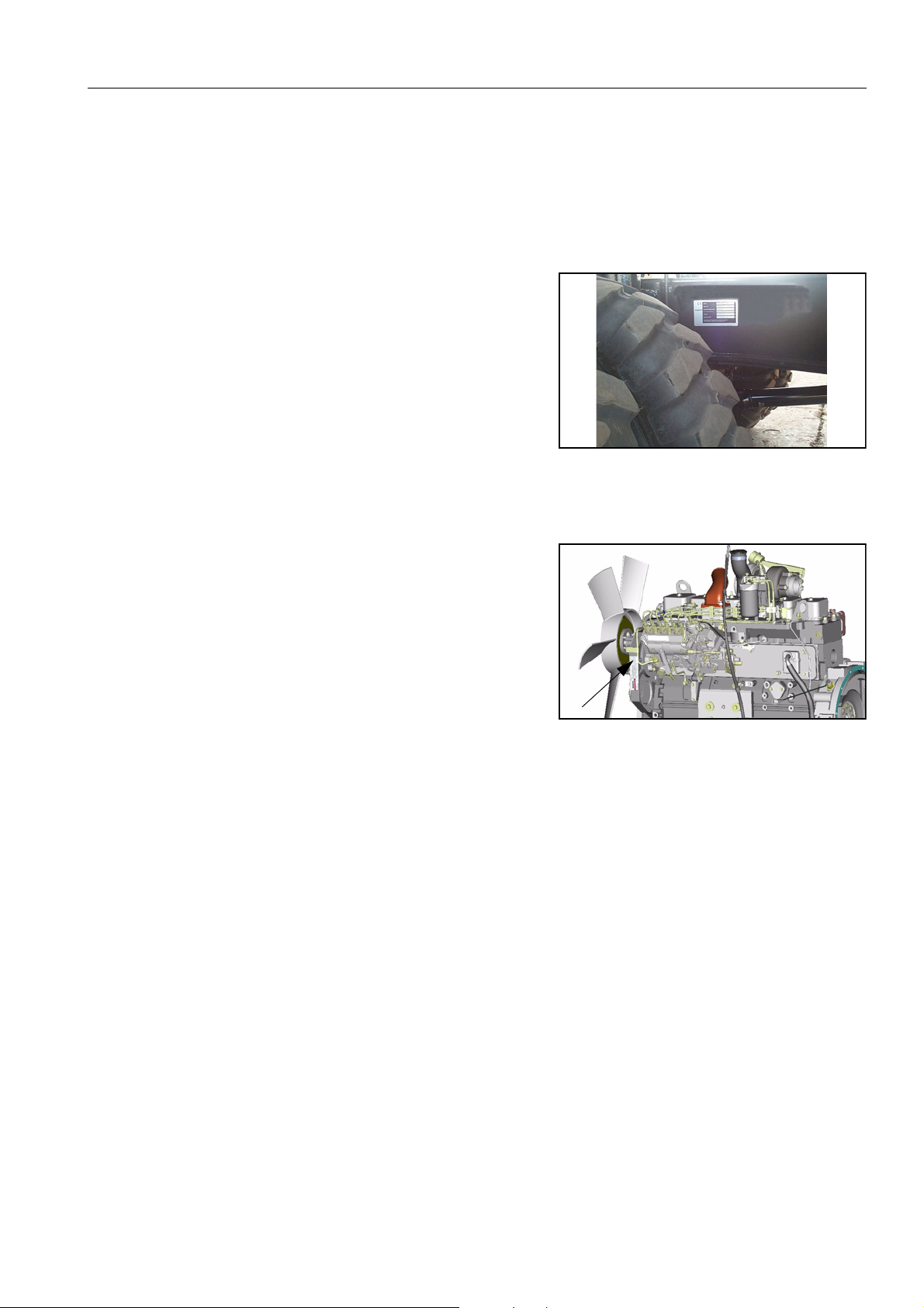
MACHINE SERIAL NO. PLATE POSITION
On the front left of the undercarriage
ENGINE SERIAL NO. PLATE POSITION
On the gear case front corner.
TABLE TO ENTER SERIAL NO. AND DISTRIBUTOR
Machine serial No.:
Engine Serial No.:
Product Identificaiton Number :
Manufacturer’s name: Komatsu UK Ltd.
Address
Durham Road
Birtley
Chester-Le-Street
County Durham DH32QX
United Kingdom
Distributor
Address
Phone
9
LOCATIONS OF PLATES, TABLE TO ENTER SERIAL NO. AND DISTRIBUTOR
MACHINE SERIAL PLATES
STANDARD SERIAL PLATE
MODEL
SERIAL No.
MANUFACT. YEAR
MAX. DRAWBAR PULL
MASS
ENGINE POWER
Product Identification Number
MANUFACTURER
Manufactured by Komatsu UK Ltd.
for Komatsu Ltd., Tokyo, Japan
Manufactured by Komatsu UK Ltd.
for Komatsu Ltd.,Tokyo,Japan
N
kg
kW
20G-00-K2382
GERMANY SERIAL PLATE
TYP
FABR. NR.
BAUJAHR
ZUL. ZUGKRAFT
ZUL.GESAMTGEWICHT
LEISTUNG
ZUL.ACHSLAST VORN
ZUL.ACHSLAST HINTEN
Produkt Identifizierung Nummer
HERSTELLER
Hergestellt vom Komatsu UK Ltd. Birtley Co Durham,
United Kingdom unter lizenz der Komatsu Ltd.
N
kg
kW
kg
kg
20G-00-K2392
10

ITALIAN SERIAL PLATE
LOCATIONS OF PLATES, TABLE TO ENTER SERIAL NO. AND DISTRIBUTOR
MANUFACTURER
TIPO
TYPE-MODEL
NUMERO DI OMOLOGAZIONE
HOMOLOGATION NUMBER
MATRICOLA
SERIAL NUMBER
MASSA TOTALE AMMISSIBILE
TOTAL MAX WEIGHT
CARICO AMMISSIBILE ASSE ANT.
WEIGHT FRONT AXLE
CARICO AMMISSIBILE ASSE POST.
WEIGHT REAR AXLE
POTENZA MOTORE
ENGINE POWER
Numero di Identificazione del Prodotto.
Product Identification Number
Massa rimorchiabile ammissibile:
— Massa rimorchiabile con frenata: non atto
— Massa rimorchiabile con frenatura indipendente: non atto
— Massa rimorchiabile con frenatura ad inerzia: non atto
— Massa rimorchiabile con frenatura assistita: non atto
Manufactured by Komatsu UK Ltd.
for Komatsu Ltd.,Tokyo,Japan.
DA
FROM
DA
FROM
DA
FROM
kW
kg
kg
kg
ANNO
YEAR
A
TO
A
TO
A
TO
20E-00-K1932
kg
kg
kg
11

LOCATIONS OF PLATES, TABLE TO ENTER SERIAL NO. AND DISTRIBUTOR
12

CONTENTS
FOREWORD ……………………………………………………………………………………………………………………………………….. 3
SAFETY INFORMATION ………………………………………………………………………………………………………………………. 4
SAFETY MESSAGES ………………………………………………………………………………………………………………….. 4
NOISE ……………………………………………………………………………………………………………………………………….. 5
VIBRATION ………………………………………………………………………………………………………………………………… 5
EMERGENCY STEERING …………………………………………………………………………………………………………… 6
INTRODUCTION ………………………………………………………………………………………………………………………………….. 7
INTENDED USE …………………………………………………………………………………………………………………………. 7
FEATURES ………………………………………………………………………………………………………………………………… 7
BREAKING IN YOUR NEW MACHINE ………………………………………………………………………………………….. 8
LOCATIONS OF PLATES, TABLE TO ENTER SERIAL NO. AND DISTRIBUTOR ……………………………………… 9
MACHINE SERIAL NO. PLATE POSITION …………………………………………………………………………………….. 9
ENGINE SERIAL NO. PLATE POSITION ………………………………………………………………………………………. 9
TABLE TO ENTER SERIAL NO. AND DISTRIBUTOR …………………………………………………………………….. 9
MACHINE SERIAL PLATES ……………………………………………………………………………………………………….. 10
SAFETY………………………………………………………………………………………………. 19
GENERAL PRECAUTIONS ………………………………………………………………………………………………………………… 20
PRECAUTION DURING OPERATION ………………………………………………………………………………………………….. 26
BEFORE STARTING ENGINE ……………………………………………………………………………………………………. 26
OPERATING MACHINE …………………………………………………………………………………………………………….. 27
TRANSPORTATION ………………………………………………………………………………………………………………….. 33
BATTERY ………………………………………………………………………………………………………………………………… 34
TOWING ………………………………………………………………………………………………………………………………….. 35
BUCKET WITH HOOK OR BUCKET LINK WITH LIFTING EYE ……………………………………………………… 36
PRECAUTIONS FOR MAINTENANCE …………………………………………………………………………………………………. 39
BEFORE CARRYING OUT MAINTENANCE ………………………………………………………………………………… 39
DURING MAINTENANCE …………………………………………………………………………………………………………… 42
POSITION FOR ATTACHING SAFETY LABELS …………………………………………………………………………………… 45
POSITION FOR ATTACHING SAFETY LABELS …………………………………………………………………………… 45
LIFTING CAPACITY CHART PW200-7K ………………………………………………………………………………………………. 53
ONE PIECE BOOM Lift capacity tables for 2.5 metre undercarriage ………………………………………………… 53
ONE PIECE BOOM Lift capacity tables for 2.75 metre undercarriage ………………………………………………. 60
TWO PIECE BOOM Lift capacity tables for 2.5 metre undercarriage ………………………………………………… 67
TWO PIECE BOOM Lift capacity tables for 2.75 metre undercarriage ………………………………………………. 74
LIFTING CAPACITY CHART PW220-7K ………………………………………………………………………………………………. 81
ONE PIECE BOOM Lift capacity tables for 2.75 metre undercarriage and heavy duty counterweight. ….. 81
13

ONE PIECE BOOM Lift capacity tables for 2.75 metre undercarriage ………………………………………………. 88
TWO PIECE BOOM Lift capacity tables for 2.75 metre undercarriage and heavy duty counterweight …… 95
TWO PIECE BOOM Lift capacity tables for 2.75 metre undercarriage …………………………………………….. 102
OPERATION……………………………………………………………………………………….. 111
GENERAL VIEW ……………………………………………………………………………………………………………………………… 112
GENERAL VIEW OF MACHINE ………………………………………………………………………………………………… 112
GENERAL VIEW OF CONTROLS AND GAUGES ……………………………………………………………………….. 113
EXPLANATION OF COMPONENTS …………………………………………………………………………………………………… 114
1. MACHINE MONITOR …………………………………………………………………………………………………………… 114
BASIC CHECK ITEMS ……………………………………………………………………………………………………………… 117
SWITCHES ……………………………………………………………………………………………………………………………………… 146
CONTROL LEVERS, PEDALS ………………………………………………………………………………………………………….. 154
FRONT WINDOW ……………………………………………………………………………………………………………………. 159
EMERGENCY EXIT FROM OPERATOR’S CAB ………………………………………………………………………….. 163
DOOR LOCK ………………………………………………………………………………………………………………………….. 164
CAP, COVER WITH LOCK ……………………………………………………………………………………………………….. 165
FUSE …………………………………………………………………………………………………………………………………….. 166
LUGGAGE TRAY …………………………………………………………………………………………………………………….. 167
ASHTRAY ………………………………………………………………………………………………………………………………. 167
CUP HOLDER ………………………………………………………………………………………………………………………… 167
HOT AND COOL BOX ……………………………………………………………………………………………………………… 167
CAB RADIO ……………………………………………………………………………………………………………………………. 168
POWER PICK-UP PORT ………………………………………………………………………………………………………….. 168
HANDLING AIR CONDITIONER ……………………………………………………………………………………………….. 169
FUSIBLE LINK ………………………………………………………………………………………………………………………… 182
CONTROLLER ……………………………………………………………………………………………………………………….. 182
TOOL BOX ……………………………………………………………………………………………………………………………… 183
REFUELLING PUMP ……………………………………………………………………………………………………………….. 183
WARNING LAMPS ………………………………………………………………………………………………………………….. 185
HANDLING ACCUMULATORS …………………………………………………………………………………………………. 186
OPERATION ……………………………………………………………………………………………………………………………………. 187
CHECK BEFORE STARTING ENGINE ………………………………………………………………………………………. 187
OPERATIONS AND CHECKS BEFORE STARTING ENGINE ………………………………………………………………. 199
STARTING ENGINE ………………………………………………………………………………………………………………… 201
MOVING MACHINE OFF ………………………………………………………………………………………………………….. 210
STEERING ……………………………………………………………………………………………………………………………… 213
TRAVELLING ON PUBLIC HIGHWAY ……………………………………………………………………………………….. 214
STOPPING & PARKING …………………………………………………………………………………………………………… 215
SWINGING (Slewing the upper carriage) ……………………………………………………………………………………. 217
OPERATION OF WORK EQUIPMENT ……………………………………………………………………………………….218
WORKING MODE SELECTION ………………………………………………………………………………………………… 221
14

PROHIBITIONS FOR OPERATION …………………………………………………………………………………………… 222
PRECAUTIONS FOR OPERATION …………………………………………………………………………………………… 223
PRECAUTIONS WHEN TRAVELLING UP OR DOWN HILLS ……………………………………………………….. 225
HOW TO ESCAPE FROM MUD ………………………………………………………………………………………………… 226
WORK POSSIBLE USING HYDRAULIC EXCAVATOR ………………………………………………………………… 226
REPLACEMENT AND INVERSION OF BUCKET ………………………………………………………………………… 228
STOPPING ENGINE ………………………………………………………………………………………………………………… 230
CHECK AFTER FINISHING WORK …………………………………………………………………………………………… 230
CHECK AFTER STOPPING ENGINE …………………………………………………………………………………………………. 231
LOCKING ……………………………………………………………………………………………………………………………….. 231
OVERLOAD WARNING DEVICE ………………………………………………………………………………………………. 231
HANDLING THE WHEELS ……………………………………………………………………………………………………….. 231
TRANSPORTATION …………………………………………………………………………………………………………………………. 235
LOADING, UNLOADING WORK ……………………………………………………………………………………………….. 235
PRECAUTIONS FOR LOADING ……………………………………………………………………………………………….. 237
PRECAUTIONS FOR TRANSPORTATION ………………………………………………………………………………… 239
TRAVELLING POSTURE …………………………………………………………………………………………………………. 240
COLD WEATHER OPERATION ………………………………………………………………………………………………………… 241
PRECAUTIONS FOR LOW TEMPERATURE ……………………………………………………………………………… 241
PRECAUTIONS AFTER COMPLETION OF WORK …………………………………………………………………….. 243
AFTER COLD WEATHER ………………………………………………………………………………………………………… 243
LONG-TERM STORAGE …………………………………………………………………………………………………………………… 244
BEFORE STORAGE ………………………………………………………………………………………………………………… 244
DURING STORAGE ………………………………………………………………………………………………………………… 244
AFTER STORAGE …………………………………………………………………………………………………………………… 245
STARTING MACHINE AFTER LONG-TERM STORAGE ……………………………………………………………… 245
TROUBLESHOOTING ………………………………………………………………………………………………………………………. 246
PHENOMENA THAT ARE NOT FAILURES ………………………………………………………………………………… 246
METHOD OF TOWING MACHINE …………………………………………………………………………………………….. 247
PRECAUTIONS ON PARTICULAR JOBSITES …………………………………………………………………………… 247
DISCHARGED BATTERY ………………………………………………………………………………………………………… 248
OTHER TROUBLE ………………………………………………………………………………………………………………….. 252
MAINTENANCE. …………………………………………………………………………………. 257
GUIDES TO MAINTENANCE …………………………………………………………………………………………………………….. 258
OUTLINE OF SERVICE …………………………………………………………………………………………………………………….. 261
USE OF BIO-DEGRADEABLE OIL ……………………………………………………………………………………………. 261
If an abnormality is found in the characteristics of the oil, change the oil immediately. ………………………. 261
OUTLINE OF OIL, FUEL, COOLANT …………………………………………………………………………………………. 262
OUTLINE OF ELECTRIC SYSTEM ……………………………………………………………………………………………. 266
OUTLINE OF HYDRAULIC SYSTEM …………………………………………………………………………………………. 266
15

WEAR PARTS LIST …………………………………………………………………………………………………………………………. 268
USE FUEL, COOLANT AND LUBRICANTS ACCORDING TO AMBIENT TEMPERATURE ……………………… 269
PROPER SELECTION OF FUEL, COOLANT AND LUBRICANTS ………………………………………………… 269
USE FUEL, COOLANT AND LUBRICANTS ACCORDING TO AMBIENT TEMPERATURE CONT. ………….. 271
STANDARD TIGHTENING TORQUES FOR BOLTS AND NUTS …………………………………………………………… 273
INTRODUCTION OF NECESSARY TOOLS ……………………………………………………………………………….. 273
TIGHTENING TORQUE SPECIFICATIONS ………………………………………………………………………………………… 274
TIGHTENING TORQUE LIST ……………………………………………………………………………………………………. 274
PERIODIC REPLACEMENT OF SAFETY CRITICAL PARTS ……………………………………………………………….. 275
SAFETY CRITICAL PARTS ………………………………………………………………………………………………………. 276
MAINTENANCE SCHEDULE CHART ………………………………………………………………………………………………… 277
KEY TO LUBRICATION POINTS ………………………………………………………………………………………………. 281
SERVICE PROCEDURE …………………………………………………………………………………………………………………… 283
INITIAL 250 HOURS SERVICE …………………………………………………………………………………………………. 283
WHEN REQUIRED ………………………………………………………………………………………………………………….. 284
CHECKING COOLANT LEVEL …………………………………………………………………………………………………. 292
CHECK AND TIGHTEN WHEEL NUTS ………………………………………………………………………………………295
CHECK ELECTRICAL INTAKE AIR HEATER ……………………………………………………………………………… 295
CHECK ALTERNATOR ……………………………………………………………………………………………………………. 295
REPLACE BUCKET SIDE CUTTERS ………………………………………………………………………………………… 296
REPLACE BUCKET TEETH ……………………………………………………………………………………………………… 297
ADJUST BUCKET CLEARANCE ………………………………………………………………………………………………. 301
CHECK WINDOW WASHER FLUID LEVEL, ADD FLUID …………………………………………………………….. 302
CHECK AND ADJUST AIR CONDITIONER ………………………………………………………………………………… 303
DRAIN ENGINE BREATHER OIL CATCHER ……………………………………………………………………………… 304
CHECK BEFORE STARTING …………………………………………………………………………………………………… 305
CHECK COOLANT LEVEL, ADD WATER ………………………………………………………………………………….. 305
EVERY 50 HOURS ………………………………………………………………………………………………………………….. 309
EVERY 100 HOURS SERVICE …………………………………………………………………………………………………. 309
EVERY 250 HOURS MAINTENANCE ………………………………………………………………………………………… 315
EVERY 500 HOURS SERVICE …………………………………………………………………………………………………. 320
EVERY 1000 HOURS SERVICE ……………………………………………………………………………………………….. 328
EVERY 2000 HOURS SERVICE ……………………………………………………………………………………………….. 334
EVERY 4000 HOURS SERVICE ……………………………………………………………………………………………….. 335
EVERY 5000 HOURS SERVICE ……………………………………………………………………………………………….. 336
SPECIFICATIONS……………………………………………………………………………….. 339
SPECIFICATIONS ……………………………………………………………………………………………………………………………. 340
1 — PIECE BOOM …………………………………………………………………………………………………………………….. 341
2 — PIECE BOOM …………………………………………………………………………………………………………………….. 343
16

WORKING RANGE: ONE PIECE BOOM ……………………………………………………………………………………. 345
WORKING RANGE: TWO PIECE BOOM …………………………………………………………………………………… 346
OPTIONS, ATTACHMENTS …………………………………………………………………. 347
GENERAL PRECAUTIONS ………………………………………………………………………………………………………………. 348
PRECAUTIONS RELATED TO SAFETY ……………………………………………………………………………………. 348
PRECAUTIONS WHEN INSTALLING ATTACHMENTS ……………………………………………………………………….. 349
HANDLING BUCKET WITH HOOK ……………………………………………………………………………………………………. 351
CHECKING FOR DAMAGE TO BUCKET WITH HOOK ……………………………………………………………….. 351
PROHIBITED OPERATIONS ……………………………………………………………………………………………………. 351
PRECAUTIONS DURING OPERATIONS …………………………………………………………………………………… 351
MACHINES READY FOR ATTACHMENTS ………………………………………………………………………………………… 352
GENERAL LOCATIONS …………………………………………………………………………………………………………… 352
HANDLING THE CLAMSHELL BUCKET ……………………………………………………………………………………. 354
OPERATION …………………………………………………………………………………………………………………………… 355
METHOD FOR RELEASING PRESSURE IN CONTROL CIRCUIT OF MACHINES EQUIPPED WITH
ACCUMULATOR …………………………………………………………………………………………………………………….. 357
LONG-TERM STORAGE ………………………………………………………………………………………………………….. 357
INTRODUCTION OF ATTACHMENTS AND EXTENDING MACHINE SERVICE LIFE ……………………………… 358
HYDRAULIC BREAKER …………………………………………………………………………………………………………… 358
POWER RIPPER …………………………………………………………………………………………………………………….. 361
FORK GRAB …………………………………………………………………………………………………………………………… 362
GRAPPLE BUCKET ………………………………………………………………………………………………………………… 363
SCRAP GRAPPLE …………………………………………………………………………………………………………………… 364
CRUSHER & SMASHER ………………………………………………………………………………………………………….. 366
HYDRAULIC PILE DRIVER ………………………………………………………………………………………………………. 367
HYDRAULIC EXCAVATOR WITH MULTIPURPOSE CRANE ……………………………………………………….. 368
17

18

SAFETY
WARNING
Read and follow all safety precautions. Failure to do so may
result in serious injury or death.
This safety section also contains precautions for optional equipment and attachments.
19
GENERAL PRECAUTIONS SAFETY
WARNING: For reasons of safety, always follow these safety precautions.
GENERAL PRECAUTIONS
SAFETY RULES
q ONLY trained and authorised personnel can operate and
maintain the machine.
q Follow all safety rules, precautions and instructions when
operating or performing maintenance on the machine.
q When working with another operator or a person on work site
traffic duty, be sure all personnel understand all hand signals
that are to be used.
SAFETY FEATURES
q Be sure all guards and covers are in their proper position.
Have guards and covers repaired if damaged.
q Use safety features such as safety lock lever at all times.
q NEVER remove any safety features. ALWAYS keep them in
good operating condition.
q Always wear safety belt when operating machine.
q Improper use of safety features could result in serious bodily
injury or death.
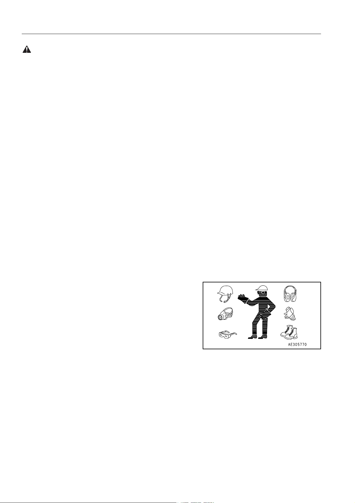
CLOTHING AND PERSONAL PROTECTIVE ITEMS
q Avoid loose clothing, jewellery, and loose long hair. They can
catch on controls or in moving parts and cause serious injury
or death. Also, do not wear oily cloths because they are flammable.
q Wear a hard hat, safety glasses, safety shoes, mask or
gloves when operating or maintaining the machine. Always
wear safety goggles, hard hat and heavy gloves if your job
involves scattering metal chips or minute materials, this is so
particularly when driving pins with a hammer and when cleaning the air cleaner element with compressed air.
Check also that there is no one near the machine.
Driving in pins, see»REPLACEMENT AND INVERSION OF
BUCKET (228)»
Cleaning of air cleaner element, see «WHEN REQUIRED
(284)» in service procedure.
UNAUTHORISED MODIFICATION
q Any modification made without authorisation from Komatsu
can create hazards.
q Before making a modification, consult your Komatsu distribu-
tor. Komatsu will not be responsible for any injury or damage
caused by any unauthorised modification.
20
SAFETY GENERAL PRECAUTIONS
WARNING: Failure to follow these safety precautions may lead to a serious accident.
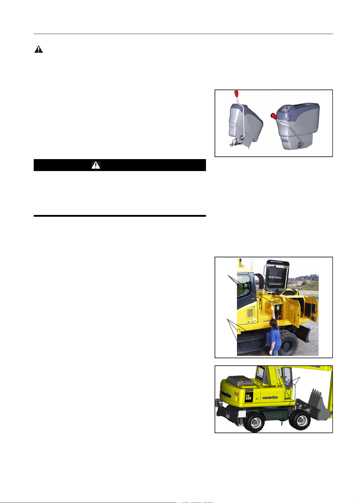
ALWAYS APPLY (RAISE) SAFETY LOCK LEVER WHEN
LEAVING OPERATOR’S SEAT
q When standing up from the operator’s seat, always raise the
safety lock lever to the LOCK position. If you accidentally
touch the travel, attachment or swing lever when they are not
locked, the machine may suddenly move and cause serious
injury or damage.
q When leaving the machine, lower the work equipment com-
pletely to the ground, set the safety lock lever to the LOCK
position, then stop the engine and use the key to lock the
machine. Always take the key with you.
LOCK
UNLOCK
WARNING
If the control lever is touched by accident, the work equipment or the machine may move suddenly, and this may lead
to a serious accident. Before leaving the operator’s compartment, always raise the safety lock lever to lock the work
equipment controls.
MOUNTING AND DISMOUNTING
q NEVER jump on or off the machine. NEVER get on or off a
moving machine.
q When mounting or dismounting, always face the machine and
use the handrails (A), machine or chassis steps (B).
q Do not hold any control levers when getting on or off the
machine.
q Ensure safety by always maintaining at least three-point con-
tact of hands and feet with the handrails, steps or wheels.
q Always remove any oil or mud from the handrails, steps and
track shoes. If they are damaged, repair them and tighten any
loose bolts.
q If grasping the door handrail when mounting or dismounting
or moving on the chassis steps, open and lock the door
securely in the open position. Otherwise, the door may move
suddenly, causing you to lose balance and fall.
A
B
A
B
21
GENERAL PRECAUTIONS SAFETY
WARNING: For reasons of safety, always follow these safety precautions.
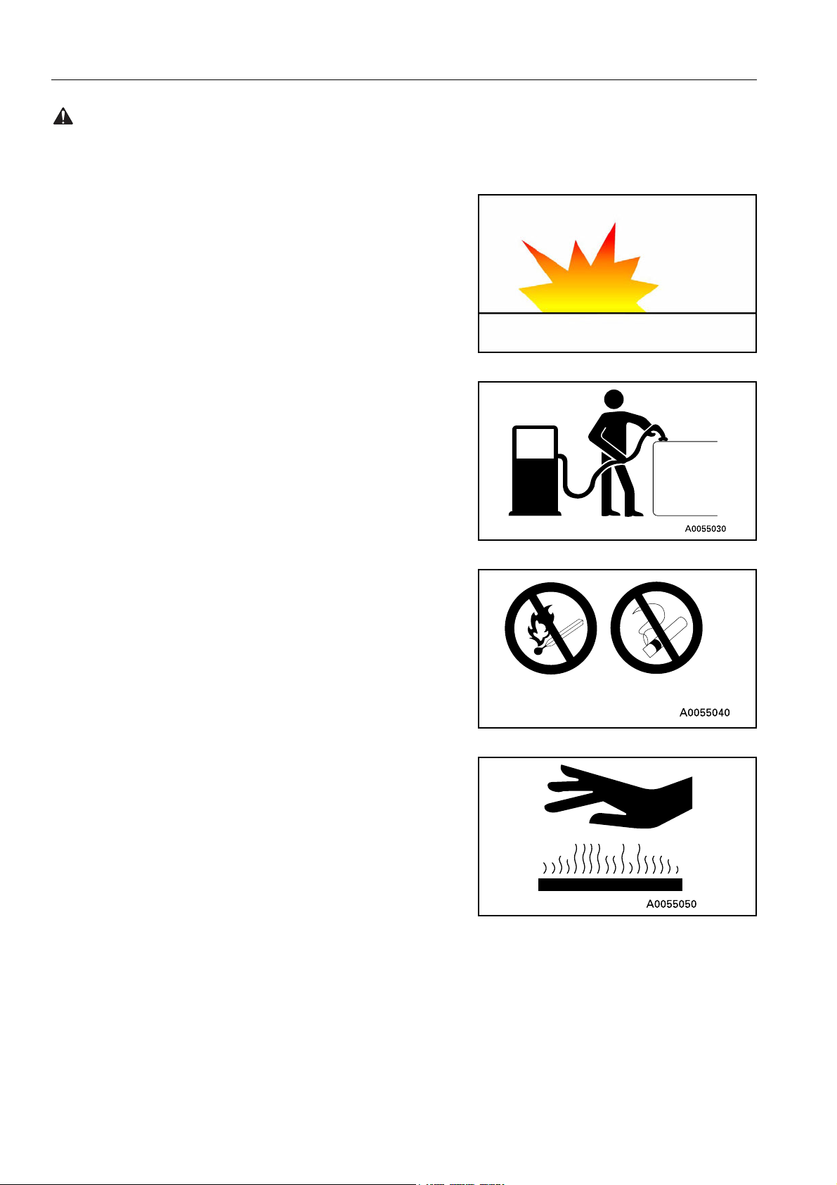
FIRE PREVENTION FOR FUEL AND OIL
Fuel, oil, and antifreeze can be ignited by a flame. Fuel is particularly FLAMMABLE and can be HAZARDOUS.
q Keep flames away from flammable fluids.
q Stop the engine and do not smoke when refuelling.
q Tighten all fuel and oil caps securely.
q Refuelling and oiling should be carried out in well ventilated
areas.
q Keep oil and fuel in a secure place and do not allow unautho-
rised persons to enter.
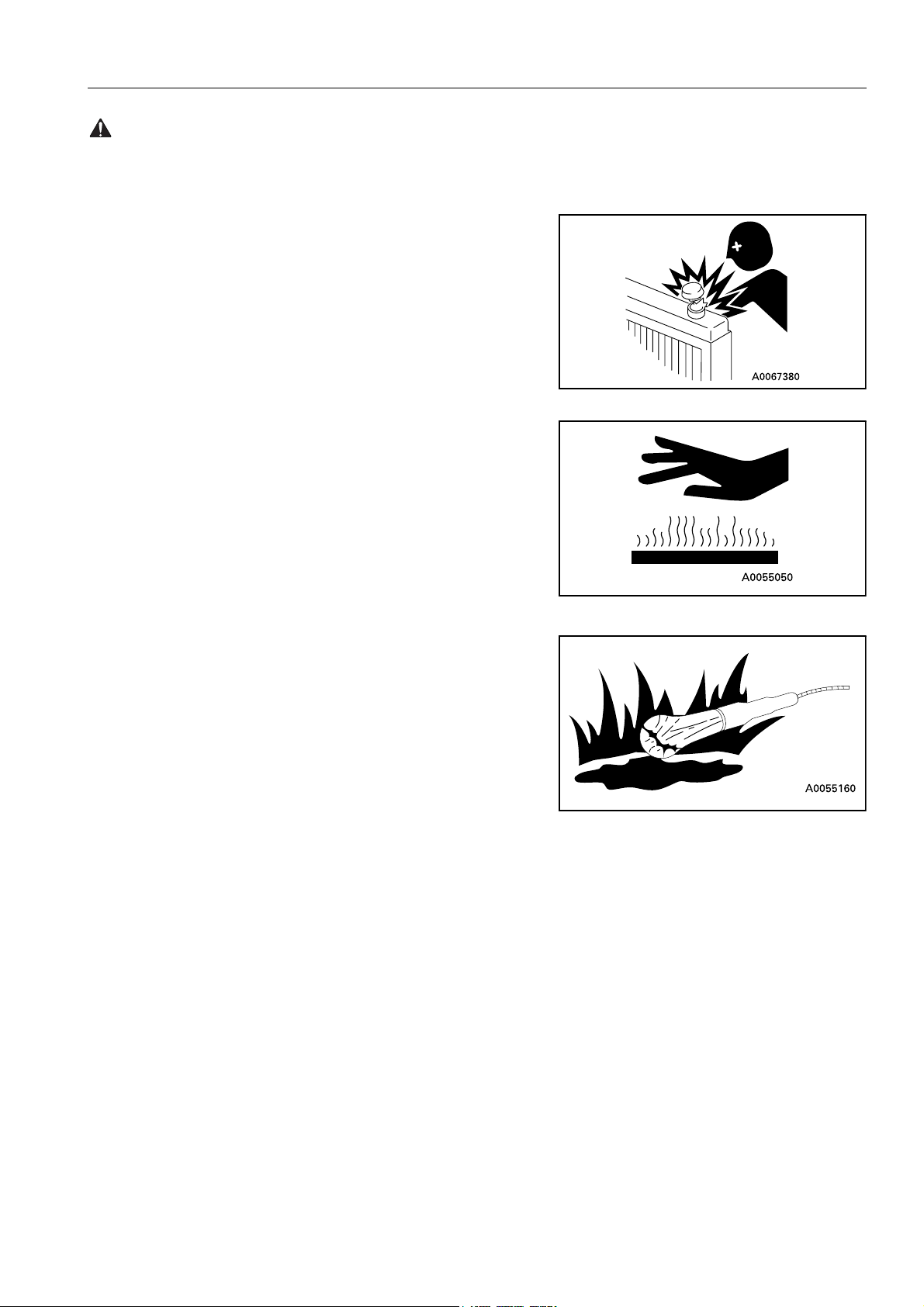
PRECAUTIONS WHEN HANDLING AT HIGH TEMPERATURES
q Immediately after operations are stopped, the engine coolant,
engine oil, and hydraulic oil are at high temperatures, and are
still under pressure. Attempting to remove the cap, drain the
oil or water, or replace the filters may lead to serious burns.
Always wait for the temperature to go down, and follow the
specified procedures when carrying out these operations.
q To prevent hot water from spurting out:
1. Turn engine off.
2. Allow water to cool.
3. Slowly loosen cap to relieve pressure before removing.
q To prevent hot oil from spurting out:
1. Turn engine off.
2. Allow oil to cool.
3. Slowly loosen cap to relieve pressure before removing.
22
SAFETY GENERAL PRECAUTIONS
WARNING: Failure to follow these safety precautions may lead to a serious accident.
MACHINES FITTED WITH WHEELS
Never perform any repair work or modifications to wheel rims
while the tyres are fitted, and never apply heat in the vicinity of the
tyres.
ASBESTOS DUST HAZARD PREVENTION
Asbestos dust can be HAZARDOUS to your health if it is inhaled.
Your Komatsu machine and genuine Komatsu spare parts do not
contain any asbestos. Use only genuine Komatsu spare parts. If
spare parts containing asbestos are used, the following precautions must be observed:
q NEVER use compressed air for cleaning.
q Use water for cleaning to keep down the dust.
q Operate the machine with the wind to your back, whenever
possible.
q Use an approved respirator if necessary.
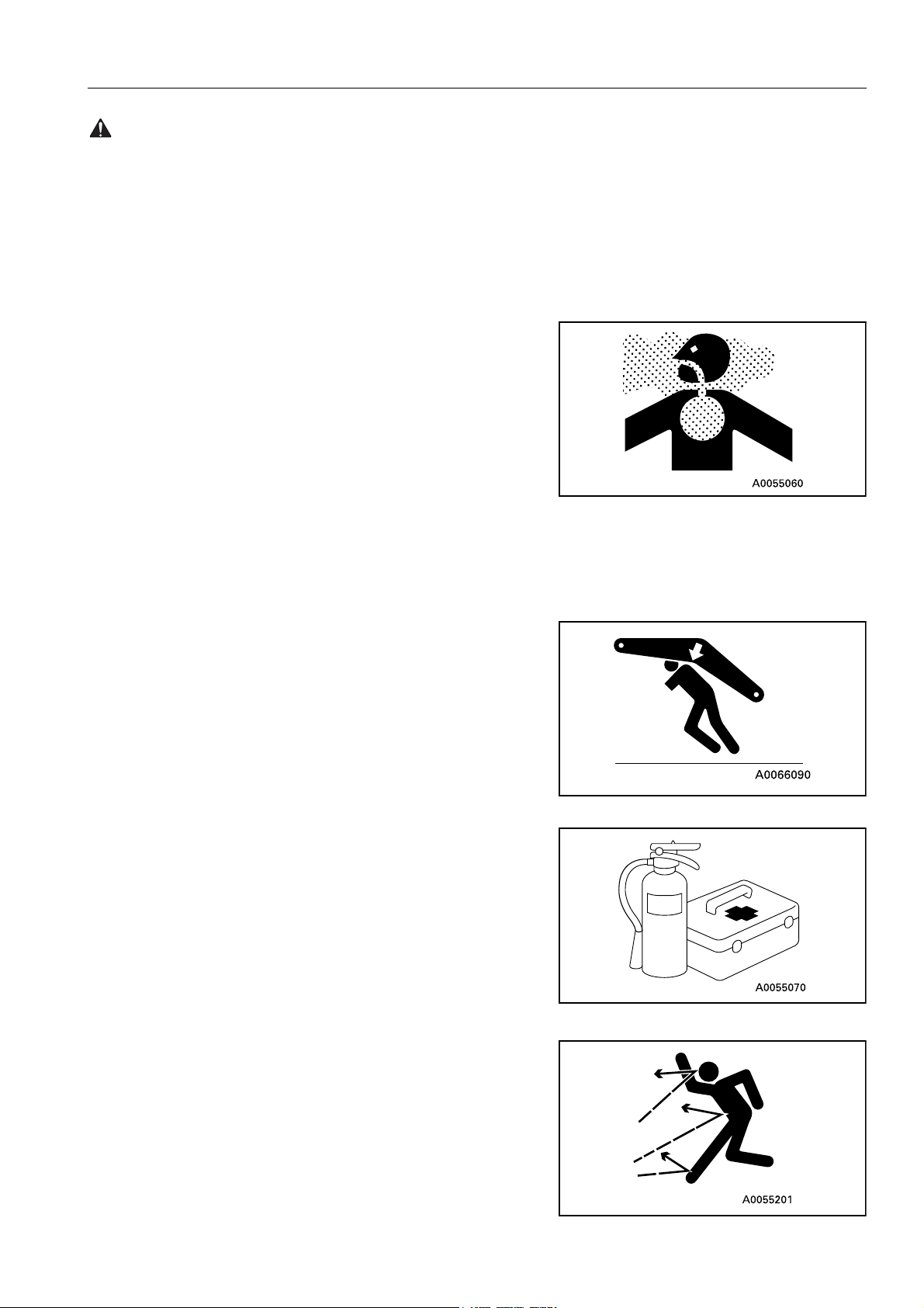
CRUSHING OR CUTTING PREVENTION
Do not enter, or put your hand or arm or any other part of your
body between movable parts such as between the work equipment and cylinders, or between the machine and work equipment.
If the work equipment is operated, the clearance will change and
this may lead to serious damage or personal injury.
FIRE EXTINGUISHER AND FIRST AID KIT
q Know how to use fire extinguisher (if installed).
q Provide a first aid kit at the storage point.
q Know what to do in the event of a fire.
q Be sure you know the phone numbers of persons you should
contact in case of an emergency.
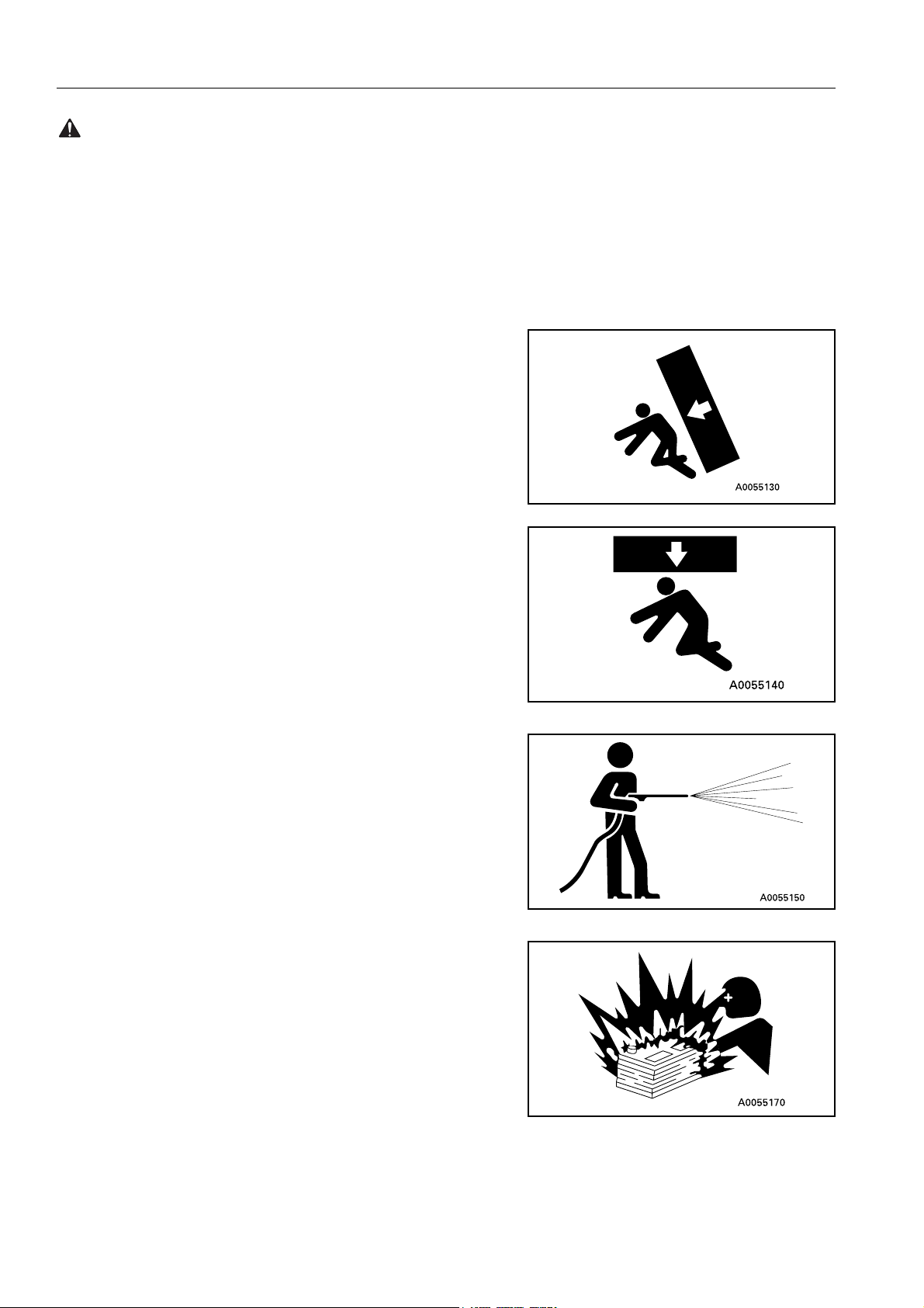
PROTECTION AGAINST FALLING OR FLYING OBJECTS
If there is any danger of falling or flying objects hitting the operator, install protective guards to protect the operator as required for
each particular situation.
q For work with breakers, install a front guard on the wind-
shield. Also, place a laminate coating sheet over the windshield.
q For demolition or shear work, install a front guard on the
windshield and a top guard on the cab. Also, place a laminate
coating sheet over the windshield.
23
GENERAL PRECAUTIONS SAFETY
WARNING: For reasons of safety, always follow these safety precautions.
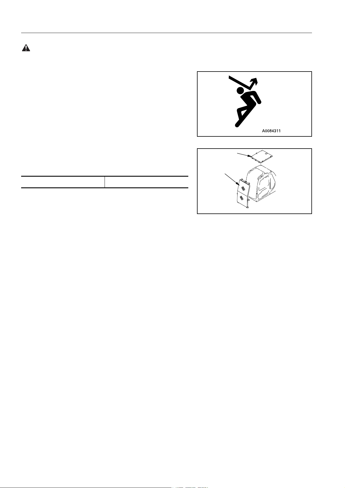
q For work in mines, quarries, demolition, tunnels or other
places where there is danger of falling rocks, put FOPS (falling object protective structure) in place. Also, place a laminate coating sheet over the windshield.
The above comments are made with regards to typical working
conditions. By all means you should put on other guards if
required by conditions at your particular site.
For details of safety guards, please contact your Komatsu distributor.
Also, even for other types of work, if there is any danger of being
hit by falling or flying objects or of objects entering the operator’s
(B)
cab, select and install a guard that matches the working conditions.
(C)
(B): Top guard (C): Front guard
Be sure to close the front window before commencing work.
When carrying out the above operations, make sure to keep all
persons other than the operator outside the range of falling or flying objects. Be particularly sure to maintain a proper distance
when carrying out shear operations.
PRECAUTIONS FOR ATTACHMENTS
q When installing and using an optional attachment, read the
instruction manual for the attachment and the information
related to attachments in this manual.
q Do not use attachments that are not authorised by Komatsu
or your Komatsu distributor. Use of unauthorised attachments
could create a safety problem and adversely affect the proper
operation and useful life of the machine.
q Any injuries, accidents, product failures resulting from the use
of unauthorised attachments will not be the responsibility of
Komatsu.
MACHINES WITH ACCUMULATOR
On machines equipped with an accumulator, for a short time after
the engine is stopped, the work equipment will lower under its
own weight when the work equipment control lever is shifted to
LOWER. After the engine is stopped, raise safety lock lever to the
LOCK position.
AB30052C
When releasing the pressure inside the work equipment circuit on
machines equipped with an accumulator, follow the procedure
given in the inspection and maintenance section.
Method of releasing pressure, see «HANDLING ACCUMULATORS (186)»
The accumulator is filled with high-pressure nitrogen gas, and it is
extremely dangerous if it is handled in the wrong way. Always
observe the following precautions.
24
SAFETY GENERAL PRECAUTIONS
WARNING: Failure to follow these safety precautions may lead to a serious accident.
q Never make any hole in the accumulator or expose it to flame
or fire.
q Do not weld anything to the accumulator.
q When carrying out disassembly or maintenance of the accu-
mulator, or when disposing of the accumulator, it is necessary
to release the gas from the accumulator. A special bleed
valve is necessary for this operation, so please contact your
Komatsu distributor.
Gas in accumulator, see «HANDLING ACCUMULATORS
(186)»
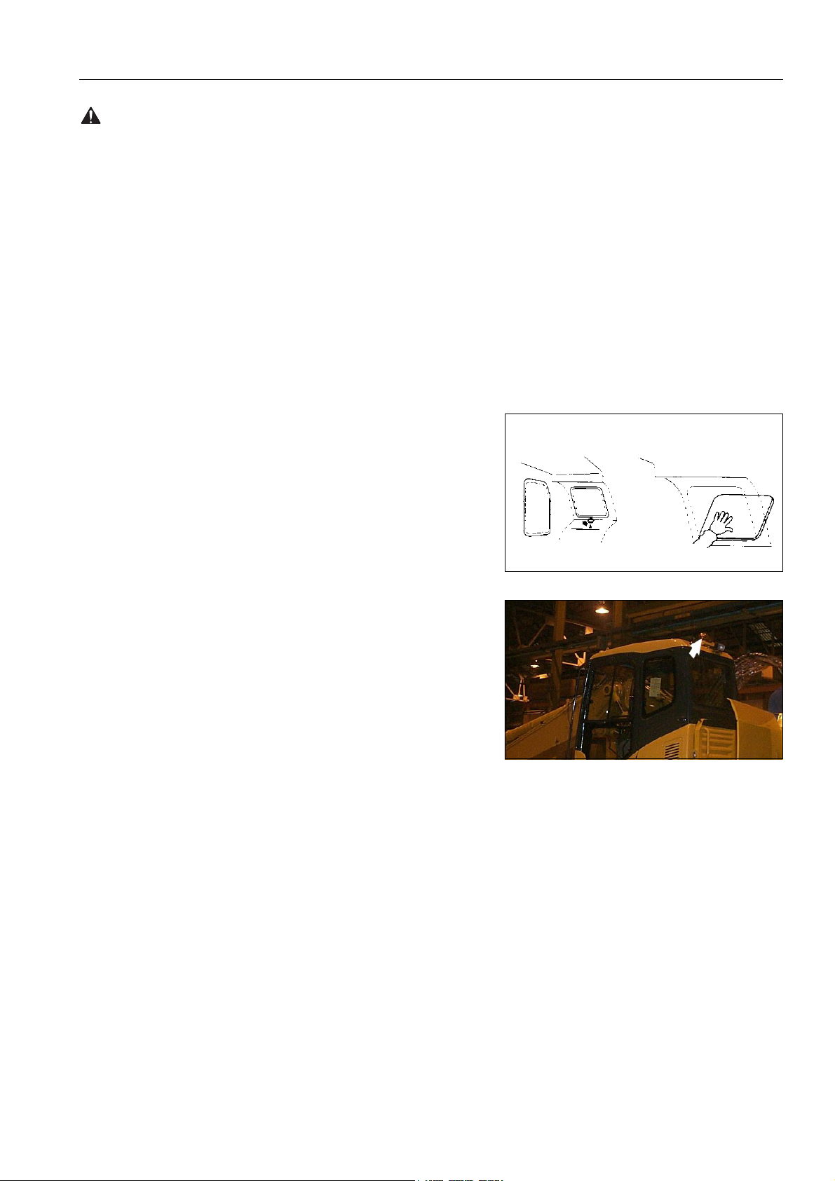
EMERGENCY EXIT
q When exit by normal means is prevented in an emergency
you can get out through the emergency exit (rear window).
q Pull the ring at the bottom of the window and remove strip.
This will allow you to push out glass.
ROTATING BEACON (Option)
q When the machine is operated on or beside a road, a rotating
beacon is required to avoid a traffic accident.
q Contact your Komatsu distributor to install beacon lamp.
ELECTROMAGNETIC INTERFERENCE
When this machine is operating close to a source of high electromagnetic interference, such as a radar station, some abnormal
phenomena may be observed.
q The display on the monitor panel may behave erratically.
q The warning buzzer may sound.
These effects do not signify a malfunction and the machine will
return to normal as soon as the source of interference is removed.
25
PRECAUTION DURING OPERATION SAFETY
WARNING: For reasons of safety, always follow these safety precautions.
PRECAUTION DURING OPERATION
BEFORE STARTING ENGINE
SAFETY AT WORKSITE
q Before starting the engine, thoroughly check the area for any
unusual conditions that could be dangerous.
q Before starting the engine, examine the terrain and soil condi-
tions of the work site. Determine the best and safest method
of operation.
q Make the slope as horizontal as possible before continuing
operations.
q If you need to operate on a street, protect pedestrians and
cars by designating a person for work site traffic duty or by
installing fences around the work site.
q If water lines, gas lines, and high-voltage electrical lines may
be buried under the work site, contact each utility and identify
their locations. Be careful not to sever or cut any of these
lines.
q Check the depth and flow of water before operating in water
or crossing a river. NEVER be in water which is in excess of
the permissible water depth.
Permissible water depth, see «PRECAUTIONS FOR
OPERATION (223)»
FIRE PREVENTION
q Thoroughly remove wood chips, leaves, paper and other
flammable things accumulated in the engine compartment.
They could cause a fire.
q Check fuel, lubrication, and hydraulic systems for leaks. Have
any leaks repaired. Wipe up any excess oil, fuel or other flammable fluids.
Check point, see «WALK-AROUND CHECK (187)»
q Be sure a fire extinguisher is present and working.
IN OPERATOR’S CAB
q Do not leave tools or spare parts lying around in the opera-
tor’s compartment. They may damage or break the control
levers or switches. Always put them in the tool box on the
front right side of the revolving frame or in the tool boxes on
the undercarriage.
q Keep the cab floor, controls, steps and handrails free of oil,
grease, snow, and excess dirt.
26
SAFETY PRECAUTION DURING OPERATION
WARNING: Failure to follow these safety precautions may lead to a serious accident.
VENTILATION FOR ENCLOSED AREAS
If it is necessary to start the engine within an enclosed area, provide adequate ventilation. Exhaust fumes from the engine can
KILL.
PRECAUTIONS FOR MIRRORS, WINDOWS AND LIGHTS
q Remove all dirt from the surface of the windows and lights to
ensure that you can see well.
q Adjust the rear view mirrors so that you can see clearly from
the operator’s seat, and always keep the surface of the mirrors clean. If any glass is broken, replace it with a new part.
q Check that the head lamps and working lamps are installed to
match the operating conditions. Check also that they light up
properly.
OPERATING MACHINE
WHEN STARTING THE ENGINE
q Walk around for machine again just before mounting it, to
check for people and objects that might be in the way.
q NEVER start the engine if a warning tag has been attached to
the wrist control.
q Before starting the engine, sound the horn as an alert.
q Start and operate the machine only while seated.
q Do not allow anyone other than the operator to ride in the cab
or on the machine body.
q For machines equipped with a reverse alarm buzzer, check
that the warning device operates correctly.
CHECK DIRECTION BEFORE STARTING MACHINE
Before operating the travel pedal, check the direction of the under
carriage.
If the fixed axle is at the front, the forward/neutral/reverse lever
and steering will function in the opposite direction.
A Fixed axle
B Oscillating axle
Travel operations, see «MOVING MACHINE OFF (210)»
B
A
27
PRECAUTION DURING OPERATION SAFETY
WARNING: For reasons of safety, always follow these safety precautions.
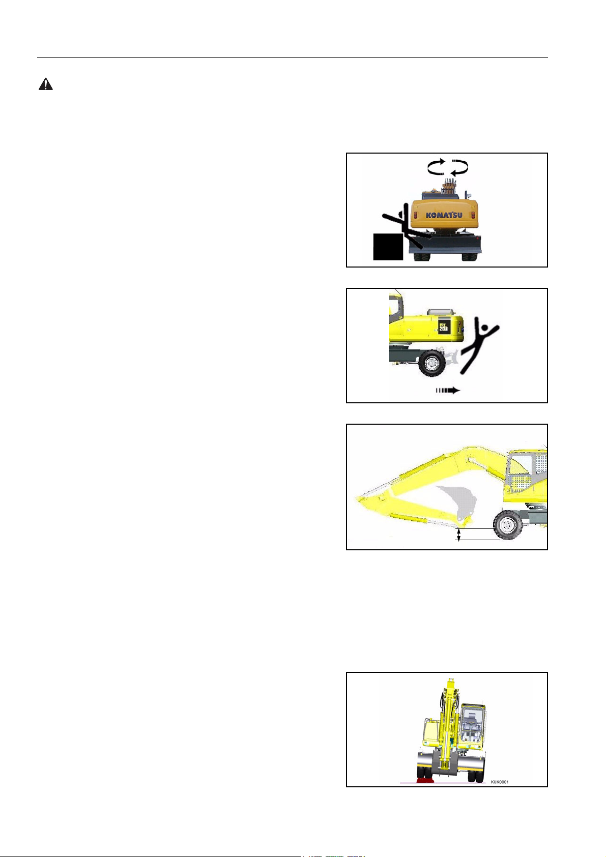
CHECK THAT NO ONE IS IN THE AREA BEFORE SWINGING
OR TRAVELLING IN REVERSE
q Always position a signalman when operating in dangerous
places or places where the view is not clear.
q Make sure that no one comes inside the swing radius or
direction of travel.
q Before starting to move, sound the horn or give a signal to
warn people not to come close to the machine.
q There are blind spots behind the machine, so if necessary,
swing the upper structure to check that there is no one behind
the machine before travelling in reverse.
PRECAUTIONS WHEN TRAVELLING
q Fold in the work equipment as shown in the diagram, and
keep it at a height of 40-50 cm from the ground level before
starting to travel.
q Before travelling on public roads, fully raise dozer blade and
outriggers, lock the outriggers in position with the safety pin,
lock the bucket and arm cylinder with isolation valves, and
insert swing lock pin.
For details, see «TRAVELLING ON PUBLIC HIGHWAY
(214)»
q When travelling on public roads the safety lock lever should
be down (UNLOCKED) and lock lever switch engaged. This
prevents operation of the control levers and activates the rear
facing brake lamp circuit.
q When travelling on rough ground, travel at low speed, and
avoid sudden changes in direction.
q Avoid travelling over obstacles as far as possible. If the
machine has to travel over an obstacle, keep the work equipment as close to the ground as possible and travel at low
speed. Never travel over obstacles which make the machine
tilt strongly (10° or more).
40 — 50cm
INCORRECT
28

SAFETY PRECAUTION DURING OPERATION
WARNING: Failure to follow these safety precautions may lead to a serious accident.
TRAVELLING ON SLOPES
q Travelling on hills, banks or slopes that are steep could result
Downhill
in the machine tipping over or slipping.
q On hills, banks or slopes, carry the bucket closer to the
ground, approximately 20 to 30 cm above the ground. In case
of emergency, quickly lower the bucket to the ground to help
the machine stop and prevent it from tipping over.
q Do not turn on slopes or travel across slopes. Always go
down to a flat place to perform these operations.
Uphill
Method of travelling on slopes, see «PRECAUTIONS
WHEN TRAVELLING UP OR DOWN HILLS (225)»
Do not travel up and down on grass, fallen leaves, and wet steel
plates. These materials may allow the machine to slip, if it is travelling sideways. Keep travel speed very low.
INCORRECT
CORRECT
29
PRECAUTION DURING OPERATION SAFETY
WARNING: For reasons of safety, always follow these safety precautions.
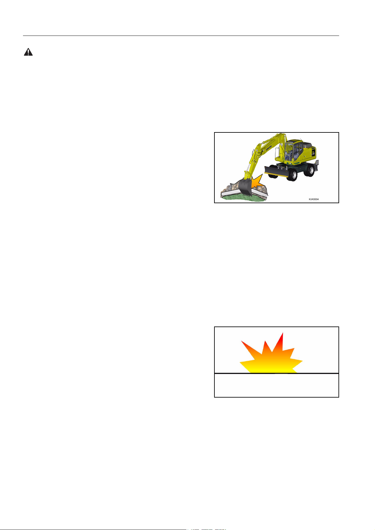
PROHIBITED OPERATIONS
q Do not dig the work face under an overhang. This may cause
INCORRECT
the overhang to collapse and fall on top of the machine.
.q Do not carry out deep digging under the front of the machine.
The ground under the machine may collapse and cause the
INCORRECT
machine to fall.
DO NOT GO CLOSE TO HIGH-VOLTAGE CABLES
Going close to high-voltage cables can cause electric shock.
Always maintain the safe distance given below, between the
machine and the electric cable.
q The following actions are effective in preventing accidents.
1) Wear shoes with rubber or leather soles.
2) Use a signalman to give warning if the machine
approaches too close to the electric cable.
q If the work equipment should touch the electric cable, the
operator should not leave the operator’s compartment.
q When carrying out operations near high voltage cables, do
not let anyone come close to the machine.
q Check with the electricity company about the voltage of the
cables before starting operations.
Voltage Min. safety distance
6.6 kV 3 m
33.0 kV 4 m
66.0 kV 5 m
154.0 kV 8 m
275.0 kV 10 m
30

SAFETY PRECAUTION DURING OPERATION
WARNING: Failure to follow these safety precautions may lead to a serious accident.
DO NOT HIT WORK EQUIPMENT
q When working in places where there are height limits, such as
in tunnels, under bridges, under electric cables, or in garages,
be extremely careful not to hit the boom or arm.
ENSURE GOOD VISIBILITY
q When working in dark places, install working lamps, and set
up lighting in the work area if necessary.
q Stop operations if the visibility is poor, such as in mist, snow,
or rain, and wait for the weather to improve to a condition that
allows the operation to be carried out safely.
OPERATE CAREFULLY ON SNOW
q When working on snow or icy roads, even a slight slope may
cause the machine to slip to the side, so always travel at low
speed and avoid sudden starting, stopping, or turning.
q When there has been heavy snow, the road shoulder and
objects placed beside the road are buried in the snow and
cannot be seen, so always carry out snow-clearing operations
carefully.
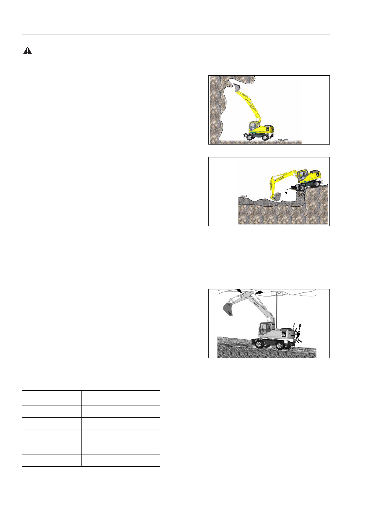
WORKING ON LOOSE GROUND
q Avoid operating your machine too close to the edge of cliffs,
overhangs, and deep ditches. If these areas collapse, your
machine could fall or tip over and result in serious injury or
death. Remember that the soil after heavy rain or blasting is
weakened in these areas.
q Earth laid on the ground and the soil near ditches are loose.
They can collapse under the weight or vibration of your
machine.
q Install the HEAD GUARD (FOPS) if working in areas where
there is danger of falling rocks and dirt.
DO NOT HIT THE OPERATOR CAB (for two piece boom only)
q When the second boom cylinder is retracted, the bucket or
the attachment can hit the operator cab or chassis.
q Operate work equipment slowly and carefully to avoid any
injury and damage.
31
PRECAUTION DURING OPERATION SAFETY
WARNING: For reasons of safety, always follow these safety precautions.
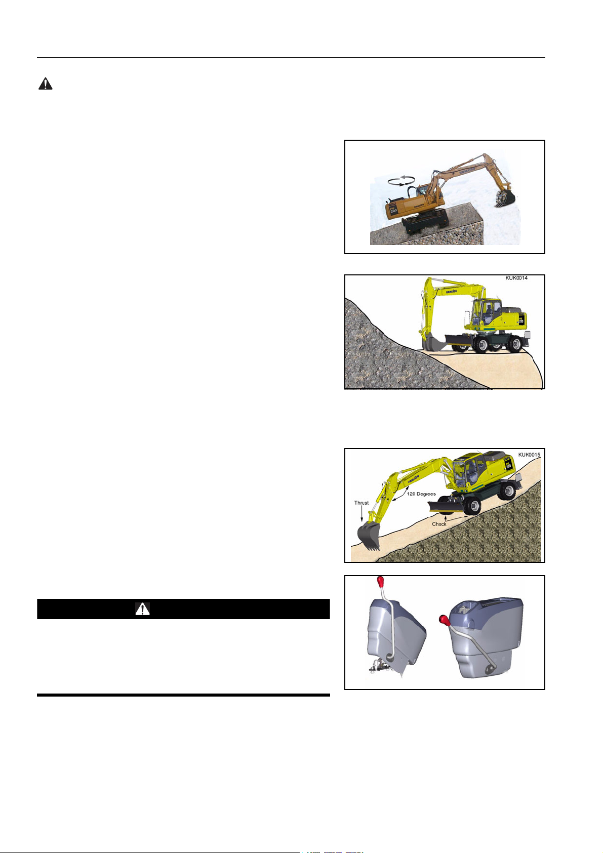
OPERATIONS ON SLOPES
q When working on slopes, there is danger that the machine
may lose its balance and turn over when the swing or work
equipment are operated. Always carry out these operations
carefully.
q Do not swing the work equipment from the uphill side to the
downhill side when the bucket is loaded. This operation is
dangerous.
(See the upper diagram on the right.)
q If the machine has to be used on a slope, pile the soil to make
a platform that will keep the machine as horizontal as possible.
(See the lower diagram on the right.)
Piled soil on slope, see «PRECAUTIONS WHEN TRAVELLING UP OR DOWN HILLS (225)»
CORRECT
INCORRECT
PARKING THE MACHINE
Park on level ground whenever possible. If not possible, chock
the wheels, lower the bucket to the ground and thrust the bucket
in the ground.
q When parking on public roads, provide fences and signs,
such as flags or lights, on the machine to warn passersby to
be careful. Be sure that the machine, flags or lights do not
obstruct traffic.
q When leaving the machine, lower the work equipment com-
pletely to the ground, raise the safety lock lever to the LOCK
position, then stop the engine and use the key to lock the
machine. Always take the key with you.
WARNING
if the control lever is touched by accident, the work equipment or the machine may move suddenly, and this may lead
to a serious accident. Before leaving the operator’s compartment, always raise the safety lock lever to lock the work
equipment controls.
CORRECT
LOCK
Platform
UNLOCK
Places to lock, see «LOCKING (231)»
32
SAFETY PRECAUTION DURING OPERATION
WARNING: Failure to follow these safety precautions may lead to a serious accident.
TRANSPORTATION
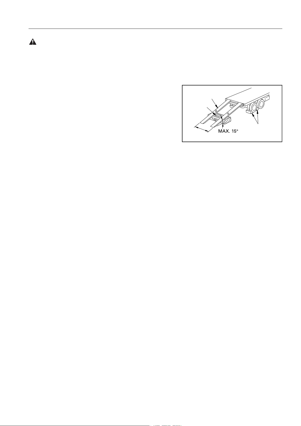
LOADING AND UNLOADING
q Loading and unloading the machine always involves potential
hazards. EXTREME CAUTION SHOULD BE USED.
When loading or unloading the machine, run the engine at
low idling and travel at low speed.
q Perform loading and unloading on firm, level ground only.
Maintain a safe distance from the edge of a road.
q ALWAYS block the wheels of the hauling vehicle and place
blocks under both ramps before loading and unloading.
q ALWAYS use ramps of adequate strength. Be sure the ramps
are wide and long enough to provide a safe loading slope.
q Be sure that the ramps are securely positioned and fastened,
and that the two sides are at the same level as one another.
Ramp
Block
Distance between ramps
Blocks
AD052900B
q Be sure the ramp surface is clean and free of grease, oil, ice
and loose materials. Remove dirt from the machine wheels.
q NEVER correct your steering on the ramps. If necessary,
drive away from the ramps and climb again.
q Swing the upper structure with extreme care on the trailer to
avoid a possible accident caused by body instability.
q After loading, block the machine wheels and secure the
machine with tie-downs.
Loading and unloading, see «TRANSPORTATION (235)»
SHIPPING
q When shipping the machine on a hauling vehicle, obey all
state and local laws governing the weight, width, and length
of a load. Also obey all applicable traffic regulations.
q Determine the shipping route while taking into account the
width, height and weight of the load.
33
PRECAUTION DURING OPERATION SAFETY
WARNING: For reasons of safety, always follow these safety precautions.
BATTERY
BATTERY HAZARD PREVENTION
q Battery electrolyte contains sulphuric acid and can quickly
burn the skin and eat holes in clothing. If you spill acid on
yourself, immediately flush the area with water.
q Battery acid could cause blindness if splashed into the eyes.
If acid gets into the eyes, flush them immediately with large
quantities of water and see a doctor at once.
q If you accidentally drink acid, drink a large quantity of water or
milk, beaten egg or vegetable oil. Call a doctor or poison prevention centre immediately.
q When working with batteries. ALWAYS wear safety glasses or
goggles.
q Batteries generate hydrogen gas. Hydrogen gas is very
EXPLOSIVE, and is easily ignited with a small spark or flame.
q Before working with batteries, stop the engine and turn the
starting switch to the OFF position.
q Avoid short-circuiting the battery terminals through accidental
contact with metallic objects, such as tools, across the terminals.
q When removing or installing, check which is the positive (+)
terminal and negative (-) terminal.
q Tighten the battery cap securely.
q Tighten the battery terminals securely. Loosened terminals
can generate sparks and lead to an explosion.
q When removing battery cap wear rubber groves to prevent
electrolyte contact with skin.
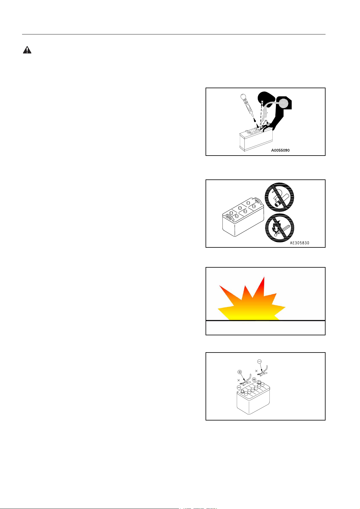
STARTING WITH BOOSTER CABLES
q ALWAYS wear safety glasses or goggles when starting the
machine with booster cables.
q When starting from another machine, do not allow the two
machines to touch.
q Be sure to connect the positive (+) cable first when installing
the booster cables. Disconnect the ground or negative (-)
cable first when removing them.
q If any tool touches between the positive (+) terminal and the
chassis, it will cause sparks. This is dangerous, so be sure to
work carefully.
INCORRECT
A0067320A
q Connect the batteries in parallel: positive to positive and neg-
ative to negative.
34
SAFETY PRECAUTION DURING OPERATION
WARNING: Failure to follow these safety precautions may lead to a serious accident.
q When connecting the ground cable to the frame of the
machine to be started, be sure to connect it as far away as
possible from the battery.
Starting with booster cables, see «DISCHARGED BATTERY (248)»
TOWING
WHEN TOWING, ATTACH WIRE TO FRAME
q Injury or death could result if a disabled machine is towed
incorrectly.
q If your machine is towed by another machine, ALWAYS use a
wire rope with a sufficient towing capacity.
q NEVER allow a disabled machine to be towed on a slope.
Towing holes
on front
q Do not use a chinked or frayed wire rope.
q If towing on the highway, a rigid tow bar should be used and
not a tow rope of any kind.
q Do not straddle the towing cable or wire rope.
q When connecting up a towing machine, do not let anyone
enter the area between the towing machine and the equipment being towed.
q Set the towing machine and the towing connection of the
equipment being towed in a straight line when connecting it.
q Place pieces of wood between the wire ropes and chassis
body to protect them from wear of damage.
Towing method, see «METHOD OF TOWING MACHINE
(247)»
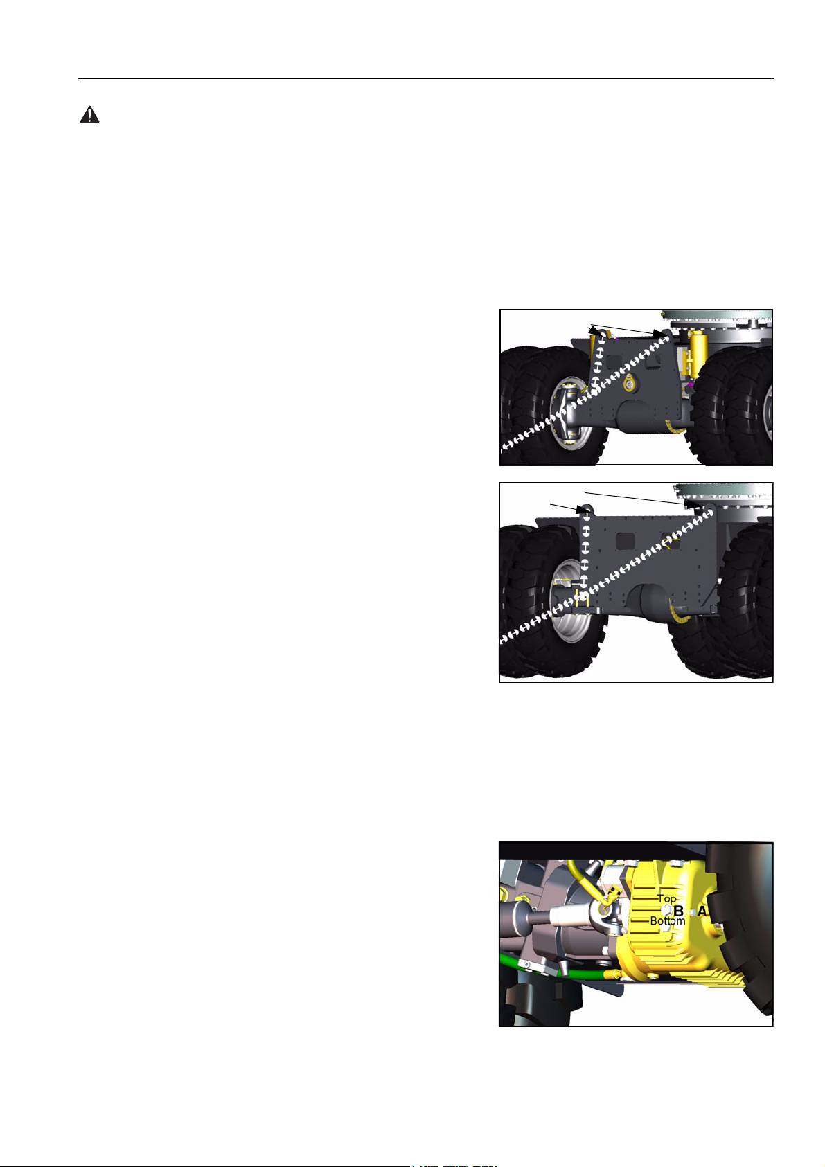
When towing the machine without the engine running or in the
advent of loss of hydraulic pressure, its is necessary to manually
release the park brake, as follows.
View on transmission
Releasing the park brake before towing:
Undercarriage
Towing holes
on rear
Undercarriage
1. Unscrew bolt (A) 2-3 turns which will allow bolt (B) to rotate
(DO NOT REMOVE BOLT ’A’).
2. Turn park brake release bolt (B) 180 degrees, the indicator
mark located at the top, moves to the bottom, which will disengage the park brake.
3. Re-tighten bolt (A) to lock the park brake in the disengaged
position for towing.
To reset the park brake:
1. Unscrew bolt (A) 2~3 turns, this allows bolt (B) to rotate.
(DO NOT REMOVE BOLT ’A’)
35
PRECAUTION DURING OPERATION SAFETY
WARNING: For reasons of safety, always follow these safety precautions.
2. Turn park brake release bolt (B) 180 degrees so that indicator
mark is located at the top position.
3. Re-tighten bolt (A)
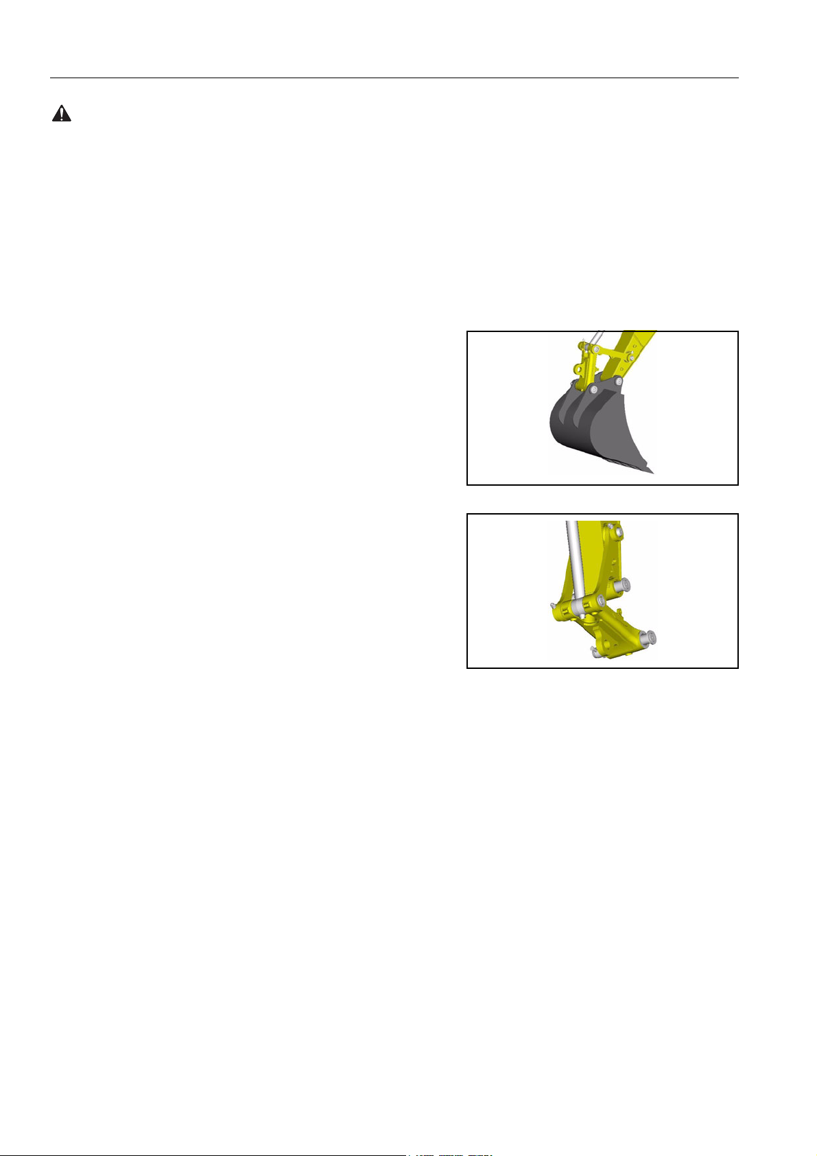
BUCKET WITH HOOK OR BUCKET LINK WITH LIFTING EYE
GENERAL PRECAUTIONS
SPECIAL HOOK
q When carrying out lifting work, a special lifting hook or lifting
eye is necessary.
q The lifting hook must be fitted with a safety latch to prevent
accidental un-hooking of the load.
q The following operations are prohibited.
Q Lifting loads with a wire rope fitted around the bucket
teeth.
Q Lifting loads with the wire rope wrapped directly around
the boom or arm.
Q Check safe working load of lifting equipment.
CHECKING HOOK
q When lifting a load, carry out the following checks to confirm
that there is no abnormality before starting operations.
Q Check that there are no cracks or deformation in the lift-
ing equipment.
Q Check that there is no abnormality in the safety latch of
the hook.
HOOKING WIRE ROPE SECURELY TO HOOK
q When performing lifting operation, securely hook the wire
rope onto the special lifting hook or lifting eye.
PRECAUTIONS FOR MACHINE INSTALLATION
q After carrying out a preliminary inspection of ground condi-
tions, select a flat, solid location. Confirm that the machine
can be safely operated without toppling or rolling.
PROHIBITED OPERATIONS OTHER THAN MAIN APPLICATIONS
q When performing lifting operation, never raise or lower a per-
son.
36

SAFETY PRECAUTION DURING OPERATION
WARNING: Failure to follow these safety precautions may lead to a serious accident.
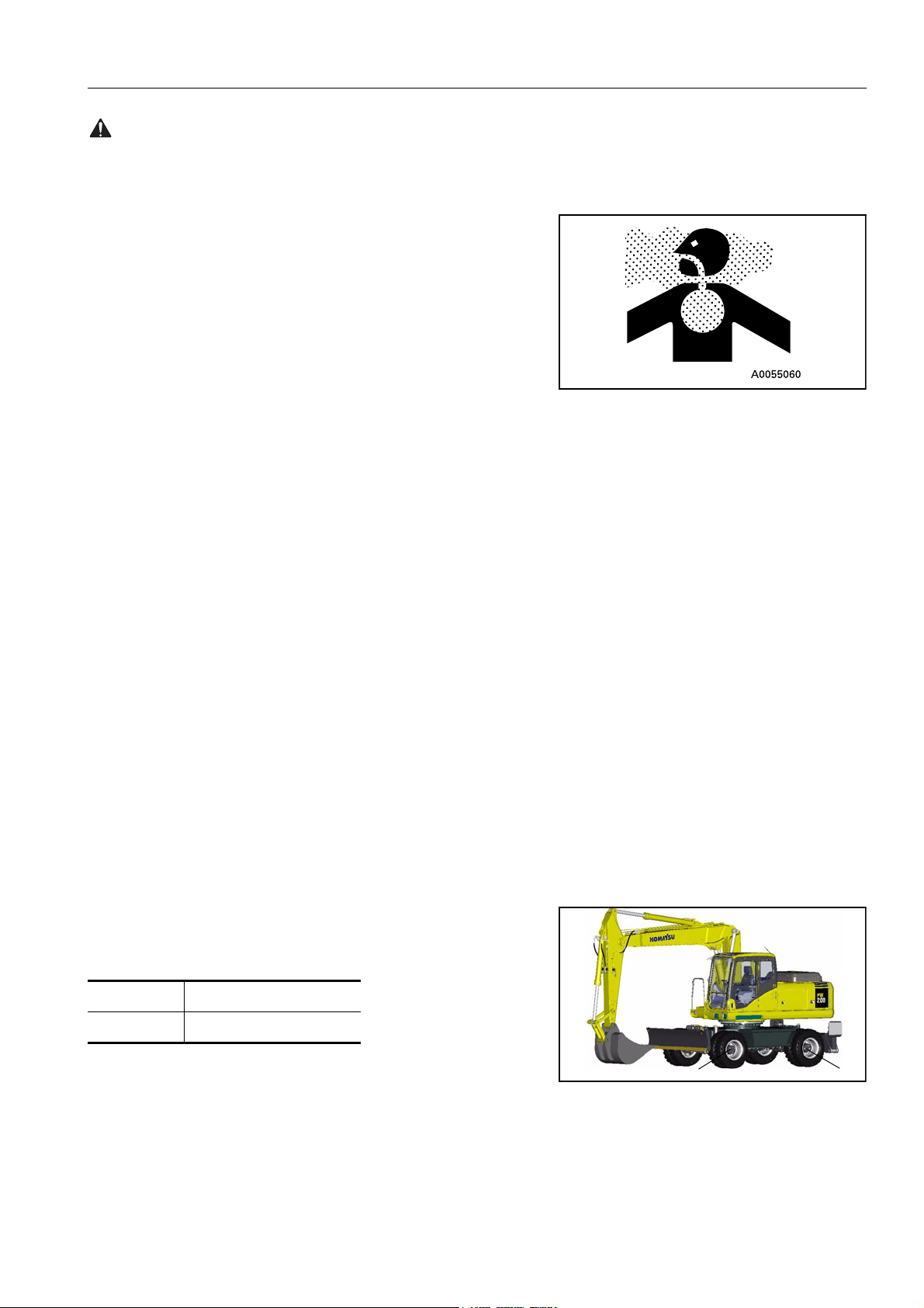
NO PERSONS SHALL BE PERMITTED TO ENTER THE
WORKING AREA
q Due to the possible danger of the load falling or of collision
with the load, no persons shall be allowed in the working
area.
OPERATION SUPERVISOR
q Before performing lifting operation, designate an operation
supervisor.
Always execute operation according to his instructions.
Q Execute operating methods and procedures under his
direction.
Q Select a person responsible for signalling. Operate only
on signals given by such person.
HANDLING OF WIRE ROPES ETC.
q Wear leather gloves when handling wire ropes.
PROTECTING EYES
q Some oils and fluids can damage eyes. Refer to manufac-
tured data sheet for handling and storage instructions.
PRECAUTIONS FOR LIFTING OPERATION
GRADUAL LIFTING OPERATION
q When carrying out lifting operations, run the engine at low
idling and use the L (lifting operation mode).
q Avoid sudden lever shifting and acceleration.
q Swing speed is three to four times that of mobile cranes.
Therefore, be especially careful when performing swing operation.
37
PRECAUTION DURING OPERATION SAFETY
WARNING: For reasons of safety, always follow these safety precautions.
NEVER LEAVE THE OPERATOR’S SEAT
q Never leave the operator’s seat while lifting a load.
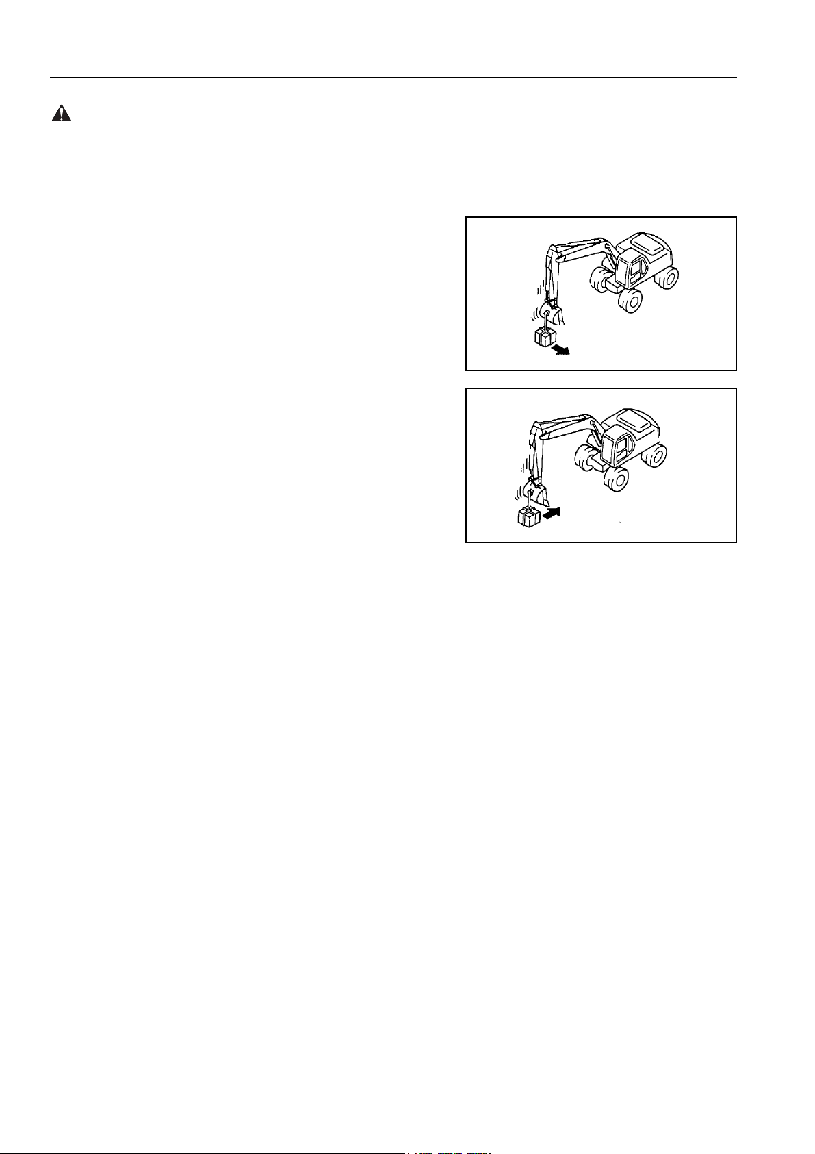
NEVER CARRY OUT EXCESSIVE OPERATIONS
q Operation exceeding machine performance may result in
INCORRECT
accident or failure.
q Carry out lifting operation within specified load limit of
machine and lifting equipment.
q Never carry out operations which may damage the machine
such as overload or over-impact-load.
q Never drag a load laterally or longitudinally, nor retract the
arm, otherwise, a dangerous situation may result.
INCORRECT
NEVER TRAVEL WHILE LIFTING A LOAD
q Never travel while carrying a load.
OPERATING POSTURE
q If the machine posture is not correct, the wire ropes or ring
may detach from the hook. Confirm that the hook angle is correct to avoid this.
HANDLING OF FLUIDS
q Some oils and other fluids, such as Antifreeze, can be harm-
ful to you and the environment, you should therefore always
follow the manufacturers instructions regarding storage, handling and disposal.
HANDLING OF USED ENGINE OILS
q Avoid contact with used engine oils.
q Refer to engine oils data sheet for handling and storage pre-
cautions.
HANDLING OF OILS
q For diesel oils, hydraulic oils and oils used in the swing
machinery, PTO, transmission axles and hubs avoid prolonged or frequent contact with skin.
q Refer to manufacturers data sheet for handling and storage
precautions.
HANDLING OF FLUIDS
q For antifreeze and grease refer to manufacturers data sheet
for handling and storage precautions.
38
SAFETY PRECAUTIONS FOR MAINTENANCE
WARNING: Failure to follow these safety precautions may lead to a serious accident.
PRECAUTIONS FOR MAINTENANCE
BEFORE CARRYING OUT MAINTENANCE
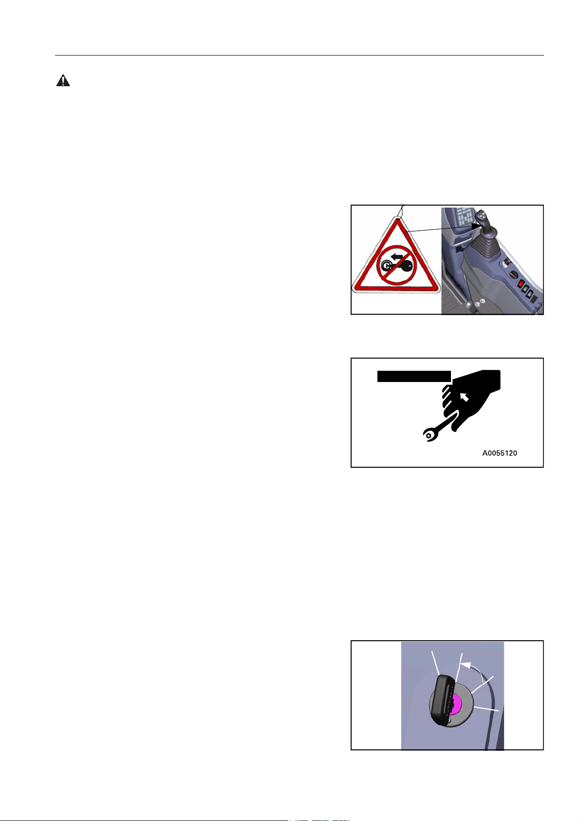
WARNING TAG
q If others start the engine or operate the controls while you are
performing service or lubrication, you could suffer serious
injury or death.
q ALWAYS attach the WARNING TAG to the control lever in the
operator’s cab to alert others that you are working on the
machine. Attach additional warning tags around the machine,
if necessary.
q These tags are available from your Komatsu distributor. (Part
no. 20E-00-K1340)
PROPER TOOLS
q Use only tools suited to the task. Using damaged, low quality,
faulty, or makeshift tools could cause personal injury.
Tools, see «INTRODUCTION OF NECESSARY TOOLS
(273)»
PERIODIC REPLACEMENT OF SAFETY CRITICAL PARTS
q Replace the following fire-related components periodically:
Fuel system: Fuel hose, spilling hose, and fuel tube cap.
Hydraulic system: Pump outlet hose.
q Replace these components periodically with new ones,
regardless of whether or not they appear to be defective.
These components deteriorate over time.
q Replace or repair any such components if any defect is found,
event though they have not reached the time specified.
Replacement of safety critical components, see «PERIODIC REPLACEMENT OF SAFETY CRITICAL PARTS
(275)»
STOP THE ENGINE BEFORE CARRYING OUT INSPECTION
AND MAINTENANCE
q Always stop the machine on firm flat ground and stop the
engine before carrying out inspection and maintenance.
q If it is necessary to run the engine when carrying out mainte-
nance, such as when cleaning the inside of the radiator,
Raise the safety lock lever to the LOCK position and carry out
the operation with two workers.
Heat
Heat
Off
Off
On
Start
On
Start
39
PRECAUTIONS FOR MAINTENANCE SAFETY
WARNING: For reasons of safety, always follow these safety precautions.
q One worker should sit in the operator’s seat so that he can
stop the engine immediately if necessary. He should also be
extremely careful not to touch any lever by mistake. Touch the
levers only when they have to be operated.
q The worker carrying out the maintenance should be
extremely careful not to touch or get caught in the moving
parts.
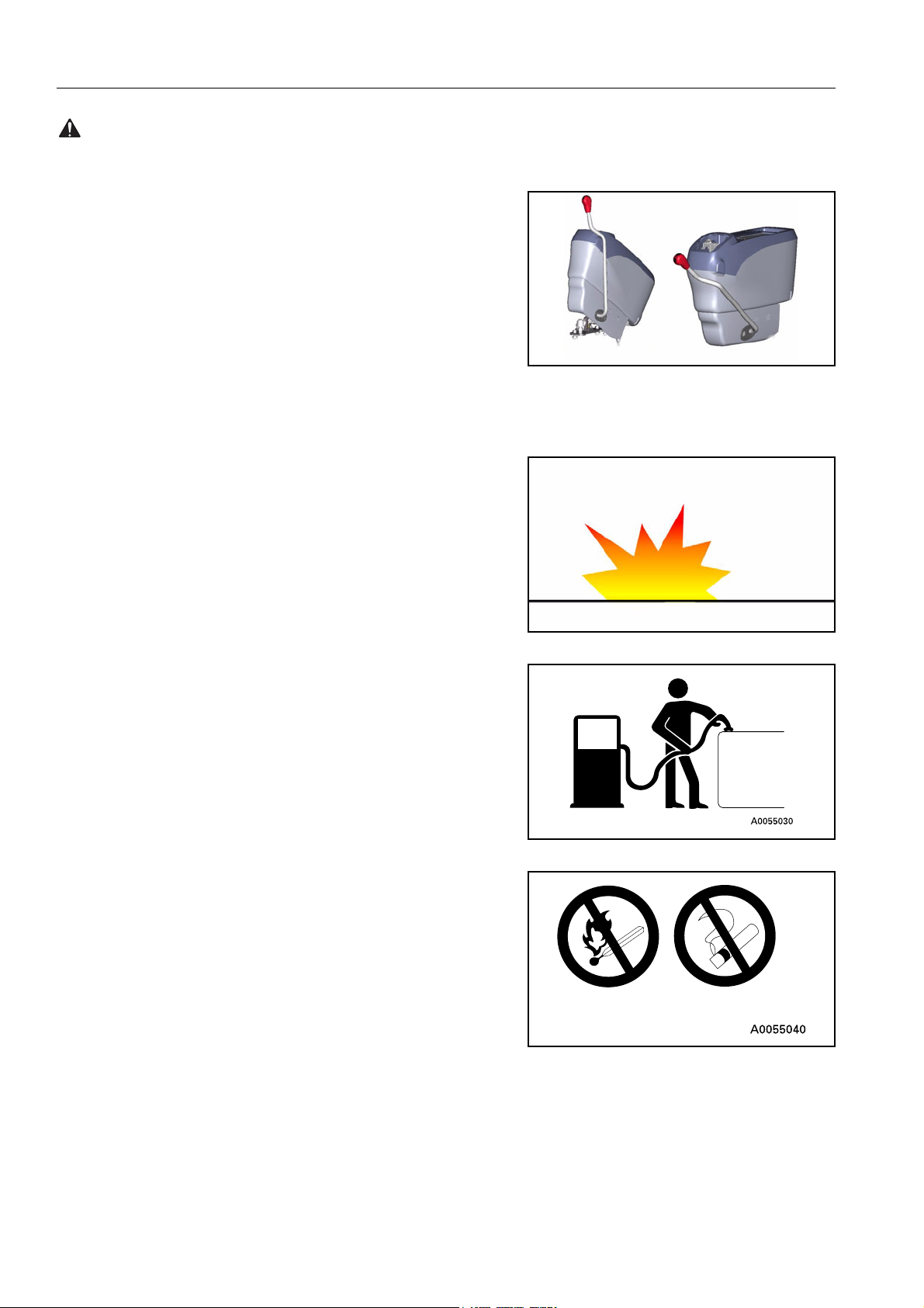
RULES TO FOLLOW WHEN ADDING FUEL OR OIL
q Spilt fuel and oil may cause you to slip, so always wipe it up
immediately.
q Always tighten the cap of the fuel and oil fillers securely.
q Never use fuel for washing any parts.
LOCK
UNLOCK
q Always add fuel and oil in a well-ventilated place.
40
SAFETY PRECAUTIONS FOR MAINTENANCE
WARNING: Failure to follow these safety precautions may lead to a serious accident.
RADIATOR WATER LEVEL
q If it is necessary to add water to the radiator, stop the engine
and allow the engine and radiator to cool down before adding
the water.
q Slowly loosen the caps to relieve pressure before removing
the caps.
USE OF LIGHTING
q When checking fuel, oil, coolant, or battery electrolyte, always
use lighting with anti-explosion specifications.
If such lighting equipment is not used, there is danger of
explosion.
41
PRECAUTIONS FOR MAINTENANCE SAFETY
WARNING: For reasons of safety, always follow these safety precautions.
DURING MAINTENANCE
PERSONNEL
q Only authorised personnel can service and repair the
machine. Extra precaution should be used when grinding,
welding, and using a sledge-hammer.
ATTACHMENTS
q Place attachments that have been removed from the machine
in a safe place so that they do not fall. If they fall on you or
others, serious injury could result.
WORK UNDER THE MACHINE
q Always lower all movable work equipment to the ground or to
their lowest position before performing service or repairs
under the machine.
q Always chock the wheels of the machine securely.
q Never work under the machine if the machine is poorly sup-
ported.
KEEP THE MACHINE CLEAN
q Spilt oil or grease, or scattered tools or broken pieces are
dangerous because they may cause you to slip or trip.
Always keep your machine clean and tidy.
q If water gets into the electrical system, there is danger that
the machine may not move or may move unexpectedly.
Do not use water or steam to clean the sensors, connectors,
or the inside of the operator’s compartment.
PRECAUTIONS WITH BATTERY
q When repairing the electrical system or when carrying out
electrical welding, remove the negative (-) terminal of the battery to stop the flow of current.
HANDLING HIGH-PRESSURE HOSES
q Do not bend high-pressure hoses or hit them with hard
objects. Do not use any bent or cracked piping, tubes or
hoses. They may burst during use.
q Always repair any loose or broken fuel hoses or oil hoses. If
fuel or oil leaks, it may cause a fire.
42
SAFETY PRECAUTIONS FOR MAINTENANCE
WARNING: Failure to follow these safety precautions may lead to a serious accident.
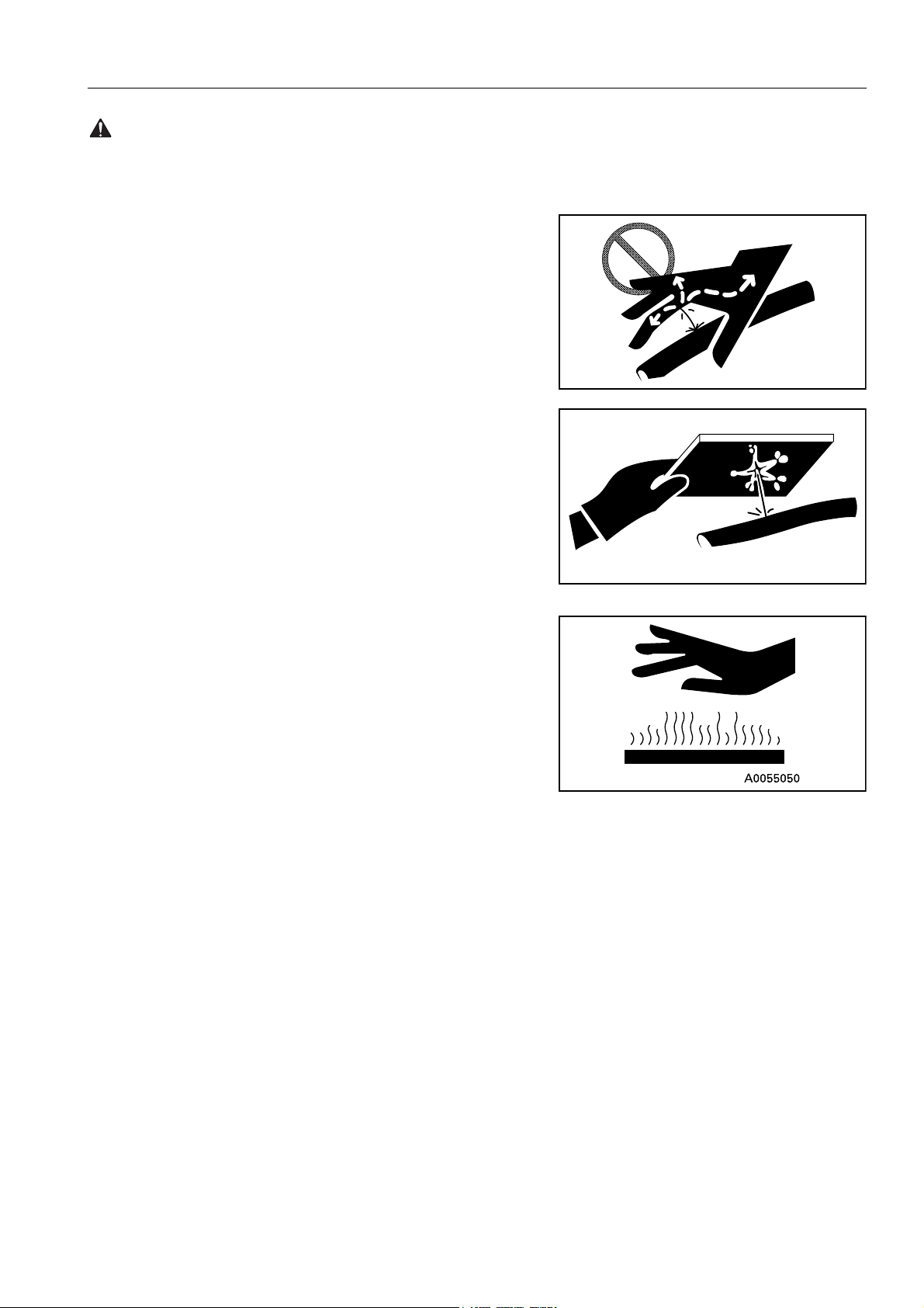
PRECAUTIONS WITH HIGH PRESSURE OIL
q Do not forget that the work equipment circuits are always
under pressure.
q Do not add oil, drain oil, or carry out maintenance or inspec-
tion before completely releasing the internal pressure.
q If oil is leaking under high pressure from small holes, it is dan-
gerous if the jet of high-pressure oil hits your skin or enters
your eyes. Always wear safety glasses and thick gloves, and
use a piece of cardboard or a sheet of wood to check for oil
leakage.
A0055180A
q If you are hit by a jet of high-pressure oil, consult a doctor
immediately for medical attention.
PRECAUTIONS WHEN CARRYING OUT MAINTENANCE AT
HIGH TEMPERATURE OR HIGH PRESSURE
q Immediately after stopping operations, the engine cooling
water and oil at all parts is at high temperature and under high
pressure.
In this condition, if the cap is removed, or the oil or water are
drained, or the filters are replaced, this may result in burns or
other injury. Wait for the temperature to go down, then carry
out the inspection and maintenance in accordance with the
procedures given in this manual.
Cleaning inside or cooling system, see «WHEN
REQUIRED (284)»
Checking cooling water level, hydraulic oil level, see
«CHECK BEFORE STARTING (305)»
Checking lubricating oil level, adding oil, see «MAINTENANCE SCHEDULE CHART (277)»
Changing oil, replacing filters, see «MAINTENANCE
SCHEDULE CHART (277)»
A055190A
43
PRECAUTIONS FOR MAINTENANCE SAFETY
WARNING: For reasons of safety, always follow these safety precautions.
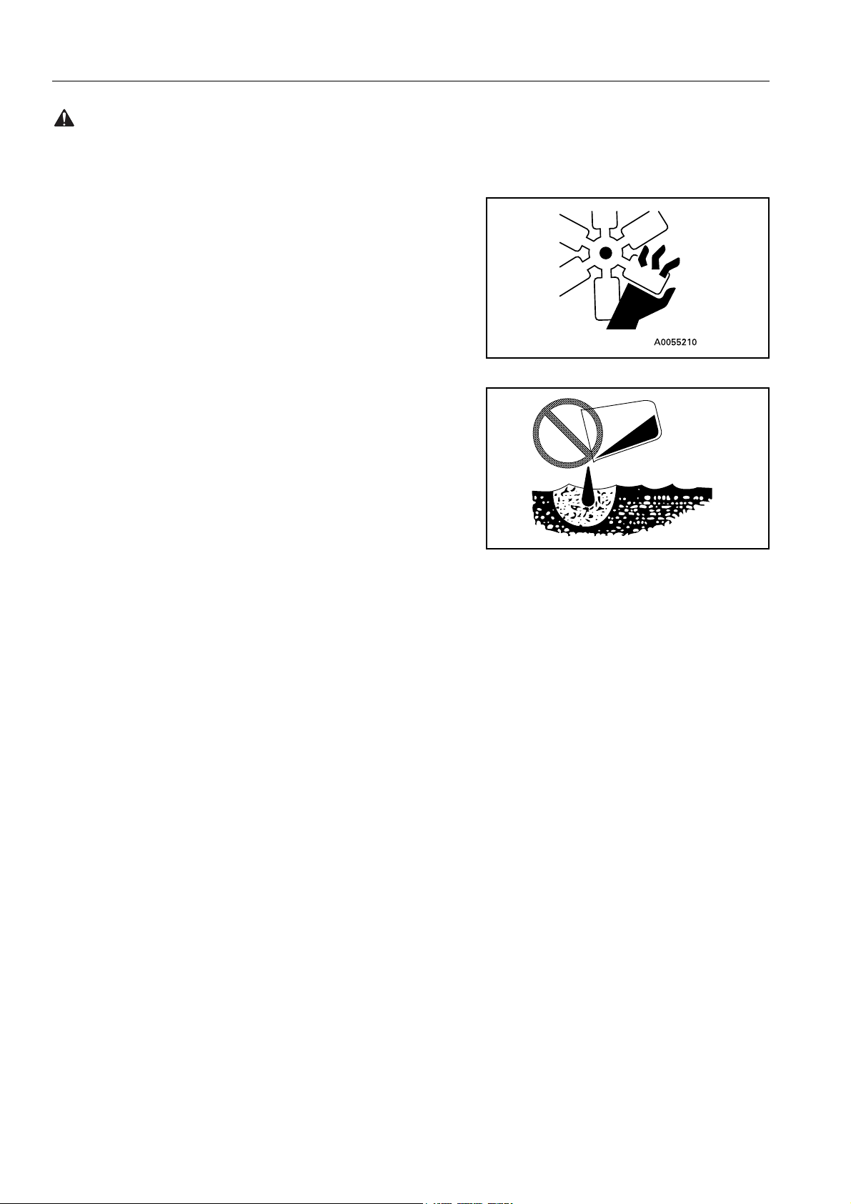
ROTATING FAN AND BELT
q Keep away from rotating parts and be careful not to let any-
thing get caught in them.
q If your body or tools touch the fan blades or fan belt, they may
be cut off or sent flying, so never touch any rotating parts.
WASTE MATERIALS
q Never dump waste oil in a sewer system, rivers, etc.
q Always put oil drained from your machine in containers.
Never drain oil directly on the ground.
q Obey appropriate laws and regulations when disposing of
harmful materials such as oil, fuel, coolant, solvent, filters,
batteries, and others.
A0055220A
44
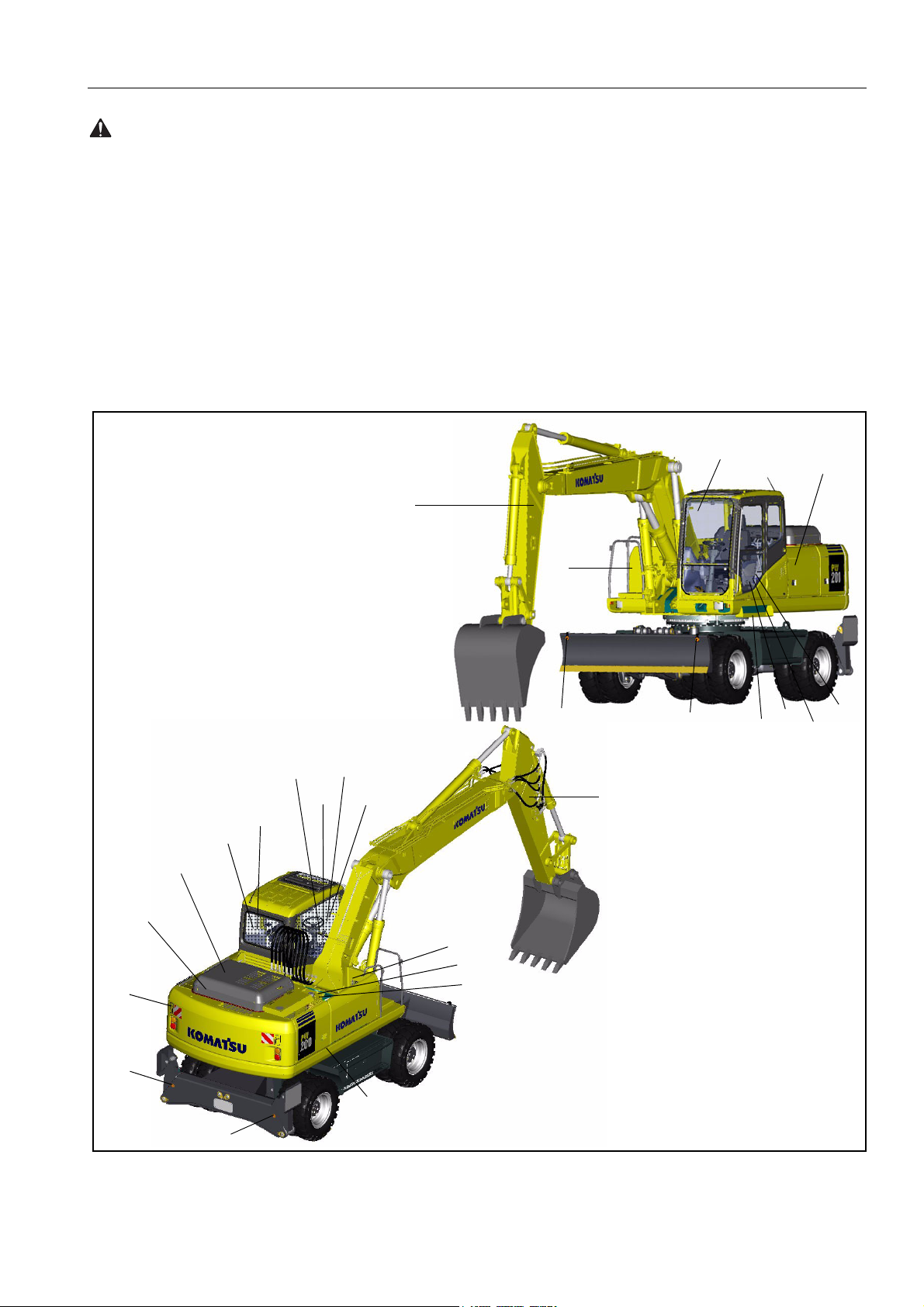
SAFETY POSITION FOR ATTACHING SAFETY LABELS
WARNING: Failure to follow these safety precautions may lead to a serious accident.
POSITION FOR ATTACHING SAFETY LABELS
Always keep these labels clean. If they are lost or damaged,
attach them again or replace them with a new label
There are other labels in addition to the safety labels listed as follows, so handle them in the same way.
Safety labels are available from your Komatsu distributor.
POSITION FOR ATTACHING SAFETY LABELS
10
16
11
19
17
8
9
15
18
1
7
8
15
4
9
3
14
13
15
6
20
12
5
2
15
6
45
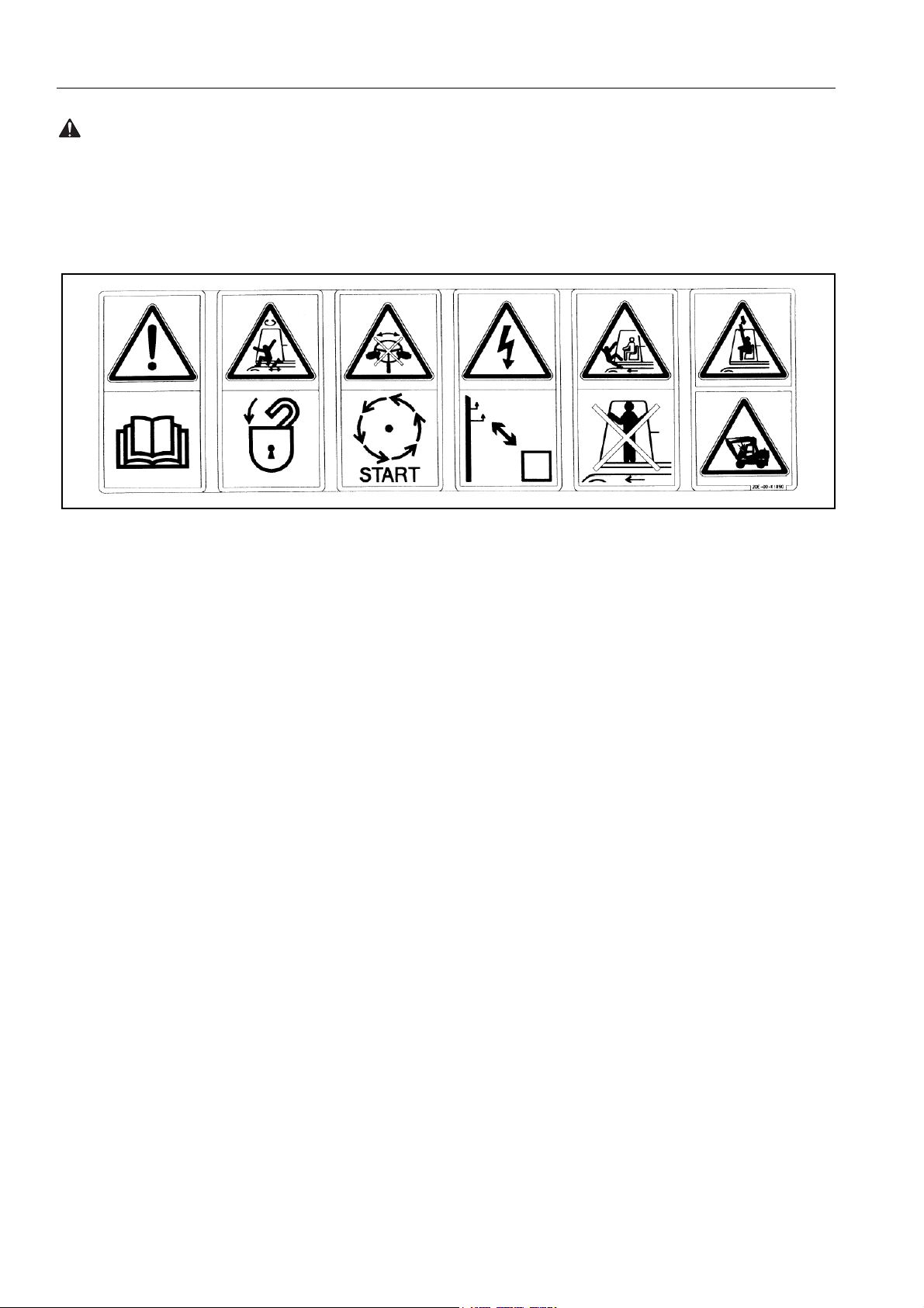
POSITION FOR ATTACHING SAFETY LABELS SAFETY
WARNING: For reasons of safety, always follow these safety precautions.
1. Warnings for read the manuals, safety lock, emergency steering, power lines, do not ride on machine, falling objects and
bucket hitting cab. This is located on the right hand window
inside the cab (20E-00-K1890)
q Improper operation and maintenance can cause serious
injury or death.
q Read the manuals before operation.
q Follow instructions and warnings in the manuals and labels
on the machine.
q Keep this manual in the machine cab, near operator.
q If this manual is lost, please contact Komatsu distributor for
replacement.
q Always raise safety lock lever when leaving operators seat.
q Normal steering can only be operated when the engine is run-
ning.
q Emergency steering is only to be used when stopping the
machine safely.
q Serious injury or death can occur if the machine or attach-
ments are not kept a safe distance away from electric lines.
q No passengers allowed to ride on machine while it is moving.
q Do not operate where a danger of falling objects exists. Con-
sult your dealer for fitting of FOPS protection.
q Bucket hits operator cab. Read manual before operation.
46
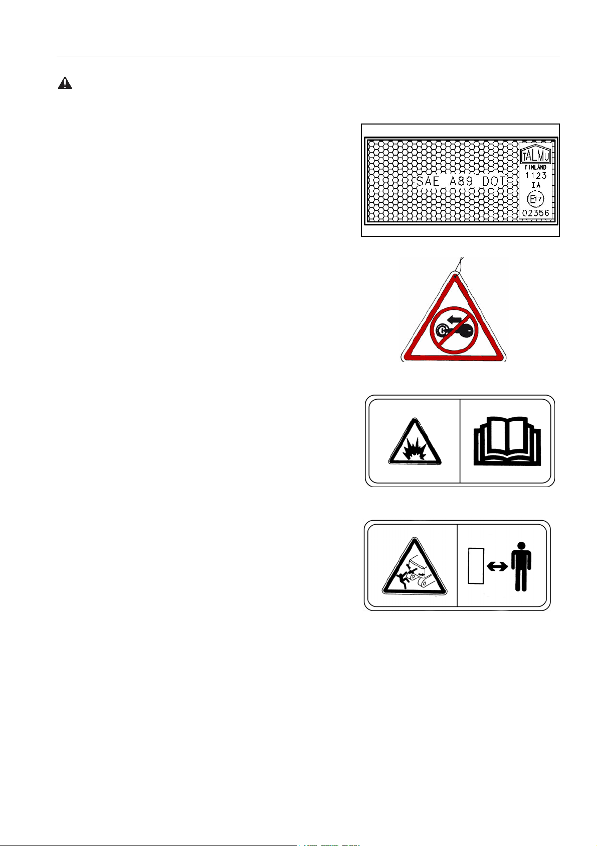
SAFETY POSITION FOR ATTACHING SAFETY LABELS
WARNING: Failure to follow these safety precautions may lead to a serious accident.
2. There are 6 amber reflectors located on the revolving frame
and arm of the machine (20G-46-K1681)
3. Warning for unsafe machine. Located on the left or right hand
levers (20E-00-K1340)
q Do not start the engine.
4. Warning for accumulator is located below operator cab
(20E-00-K1210)
Warnings for handling accumulator.
Explosion hazard
q Keep away from flame.
q Do not weld or drill.
q Read operation manual before operation.
5. Warning for staying clear (20K-00-31280)
Keeping out of moving area.
To prevent SEVERE INJURY or DEATH.
Do the following before moving the machine or its attachments:
q Sound horn to alert people nearby.
q Be sure no one is on or near machine or in the swing area.
q Rotate cab for full view of travel path if it can be done safely.
q Use spotter if view is obstructed. Follow above even if
machine equipped with travel alarm and mirrors.
47
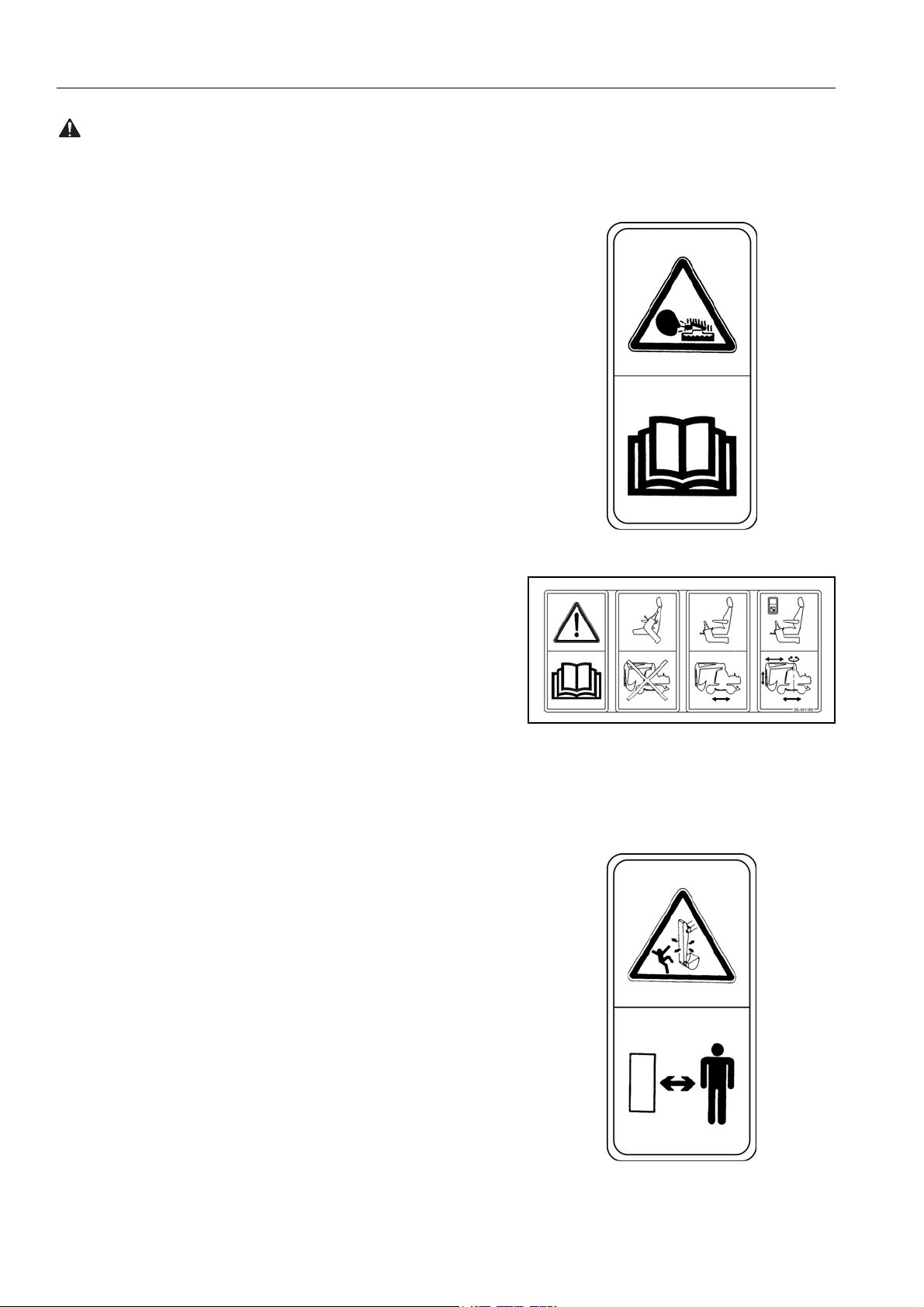
POSITION FOR ATTACHING SAFETY LABELS SAFETY
WARNING: For reasons of safety, always follow these safety precautions.
6. Warning for hot objects (20E-00-K1190)
Warning for high temperature coolant and oil, hot water and oil
hazard.
To prevent hot water and oil from spurting out:
q Turn engine off.
q Allow water to cool.
q Slowly loosen cap to relieve pressure before removing.
q Read operation manual before operation.
7. Safety lock. This is located on the right hand window of the
machine (20E-00-K1850)
q Read operation manual before operation.
q With safety lock lever raised the control levers are disabled.
q With safety lock lever lowered and control lever lock switch on
the machine can travel.
q With safety lock lever lowered and control lever lock switch off
work equipment and travel can be operated.
8. Warning for staying clear. This is fitted on both sides of arm
(20E-00-K1140)
Keeping out of moving area.
To prevent SEVERE INJURY or DEATH.
Do the following before moving the machine or its attachments:
q Sound horn to alert people nearby.
q Be sure no one is on or near machine or in the swing area.
q Rotate cab for full view of travel path if it can be done safely.
q Use spotter if view is obstructed. Follow above even if
machine equipped with travel alarm and mirrors.
48
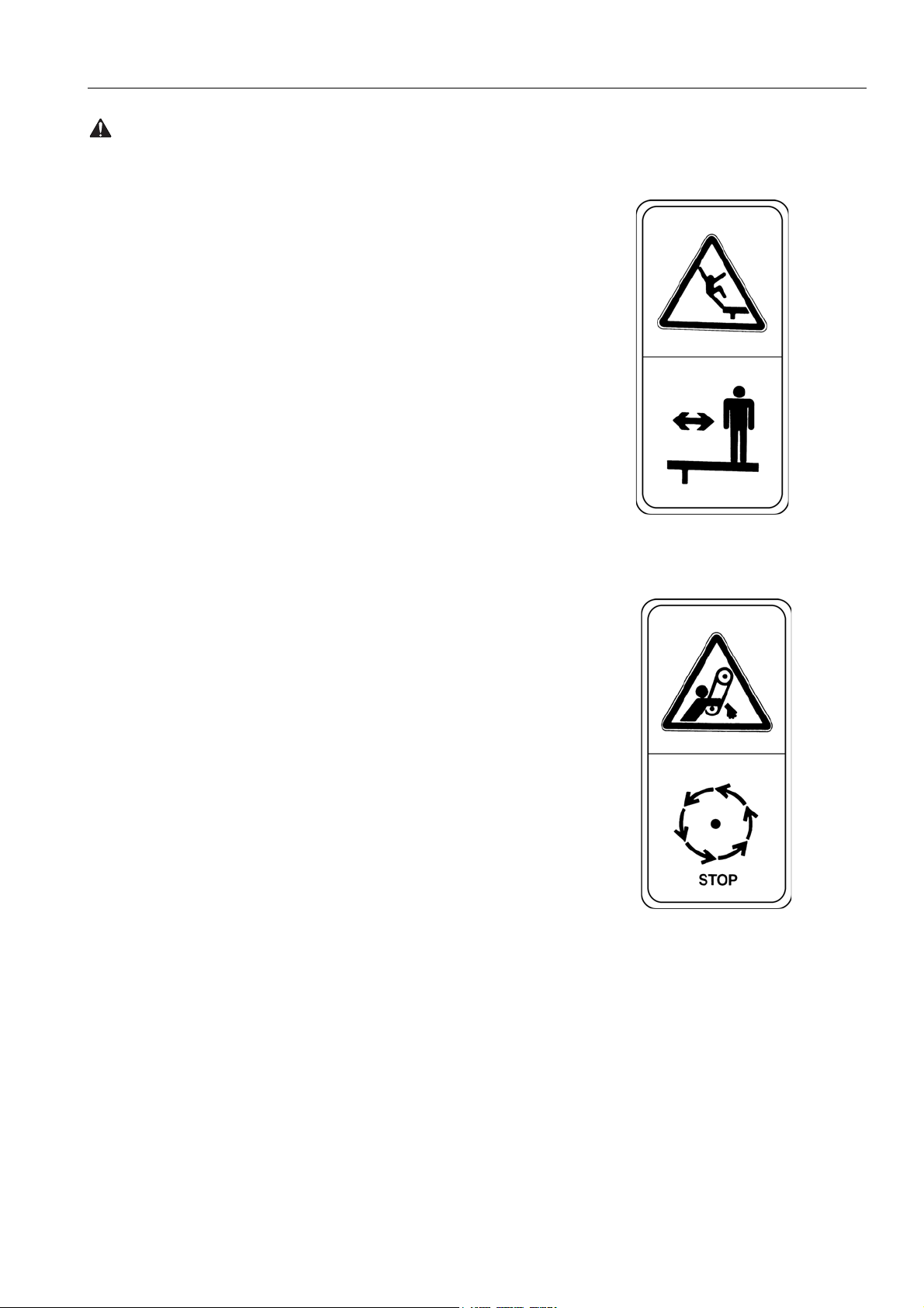
SAFETY POSITION FOR ATTACHING SAFETY LABELS
WARNING: Failure to follow these safety precautions may lead to a serious accident.
9. Falling from upper structure warning. This is located on the
front of the fuel tank, on inside of walkway door, top of the
counterweight.(20E-00-K1110)
q WARNING
falling from upper structure.
q Keep away from sides of machine.
q Keep off counterweight.
q Do not ride on machine when it is moving.
10. Stop engine warning (20E-00-K1310)
q Do not open cover while engine is running.
49
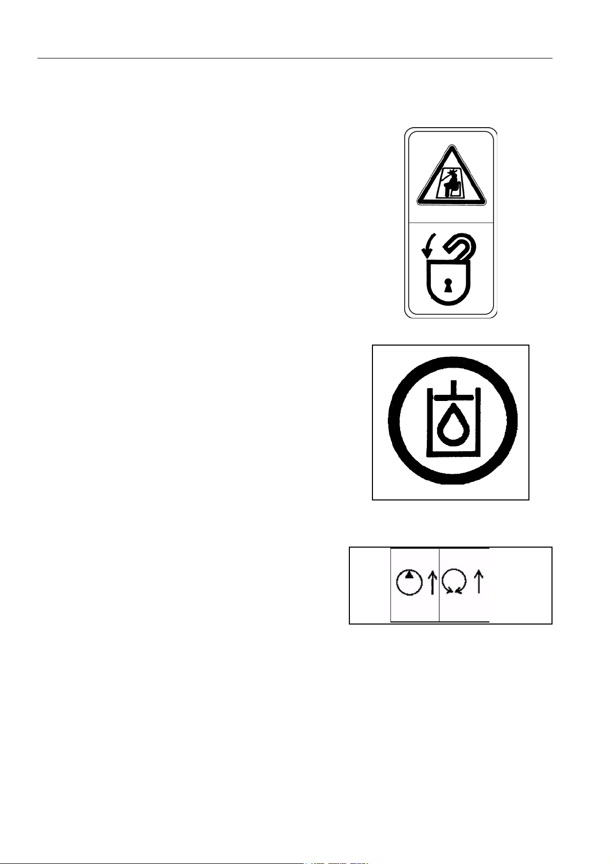
POSITION FOR ATTACHING SAFETY LABELS SAFETY
11. Front window lock warning. This is located on the rear window (20E-00-K1230)
q Always lock window in raised or lowered position.
12. High pressure oil warning (20E-00-K1270)
13. (20E-00-31350)
Pump control override switch and swing lock override switch. This
is located inside the cab.
50
 Loading…