Service Manual KX125J
Item # 99924-1153-02
MSRP
$46.40
Kawasaki service manuals contain enough detail and basic information to make them useful to the owner who desires to do his own basic maintenance and repair work. A basic knowledge of mechanics, the proper use of tools, and workshop procedures must be understood in order to carry out the work satisfactorily.
Most items ship to dealer within 5-7 business days for free. Special dealer only items may be excluded.
Additional shipping charges apply to qualified ship to home orders.
Price and specifications are subject to change without notice or liability. Availability is subject to production, stocking and demand. Manufacturers suggested retail prices shown.
 WARNING: Cancer and reproductive harm www.P65Warnings.ca.gov
- WARRANTY INFORMATION
File Specifications:795/795339-kx125.pdf file (26 Jun 2023) |
Accompanying Data:
Kawasaki KX125 Motorcycle PDF Service Manual (Updated: Monday 26th of June 2023 05:25:11 AM)
Rating: 4.5 (rated by 63 users)
Compatible devices: Z1000SX 2012, KLR650 -, NINJA ZX-12R, Contours 1000GTR, KLR650 2014, Ninja Super Sport Ninja, Ninja ZX-10R 2013, VN800-A.
Recommended Documentation:
Service Manual (Text Version):
(Ocr-Read Summary of Contents of some pages of the Kawasaki KX125 Document (Main Content), UPD: 26 June 2023)
-
Kawasaki KX125 User Manual
-
Kawasaki KX125 User Guide
-
Kawasaki KX125 PDF Manual
-
Kawasaki KX125 Owner’s Manuals
Recommended: 710 Gardener, M61WH74S, SCAK240 — HES SYSTEM, HII 63500 T, HD7002
Links & Tools
-
90cc Dirt RunnerRead this manual carefully. It contains important safety information.No one under the age of 16 should operate this dirt bike. Always wear a helmet; It could save your Life!Do not remove this operator’s manual from this vehicle.Please obtain, review, and follow provincial / municipal government …
Dirt Runner 90cc 66
-
Top1st cover4th coverTop1st cover4th cover8 mm8 mmNo.346 VZ1500 99011-40H50-03A 2/1No.346 VZ1500 99011-40H50-03A 2/1 DIC184(TDP006) DIC15799011-40H50-03AVZ1500VZ1500Part No. 99011-40H50-03AJuly, 2008 ENTKK9Printed in Japan300 TAKATSUKA, MINAMI, HAMAMATSU, JAPAN99011-40H50-03AVZ1500VZ15 …
VZ1500 195
-
Comparison chartSUZUKIBOULEVARD C90THONDAINTERSTATEYAMAHAV-Star TourerOverall length 2,560 mm (100.8 in.) 2,650 mm 2,490 mmSeat height 720 mm (28.3 in.) 681 mm 690 mmCurb mass 363 kg (800 lbs) 323 kg 323 kgDisplacement 1462 cm3 (89.2 cu. in) 1312 cm31304 cm3Max output 59.6 kw / 4,800 40 kw / 4,250 …
2013 C90T Boulevard 2
-
9 9 5 0 1 — 3 1 1 5 0 — 0 1 E背厚 4 mmPrinted in JapanK7USE THIS MANUAL WITH:RV125 SERVICE MANUAL (99500-31233-01E)RV125 DIC120No.3900 RV125K7_01E SUPPLY 99500-31150-01E 2006.8.28 Cover_14 PS Printing (4 mm) 2/1 K7 …
shogun sports 125 107
Operating Impressions, Questions and Answers:
![]()
Motorcycle
Service Manual

Quick Reference Guide
This quick reference guide will assist you in locating a desired topic or procedure.
•Bend the pages back to match the black tab of the desired chapter number with the black tab on the edge at each table of contents page.
•Refer to the sectional table of contents for the exact pages to locate the specific topic required.
|
General Information |
1 |
j |
|
Periodic Maintenance |
2 |
j |
|
Fuel System |
3 |
j |
|
Cooling System |
4 |
j |
|
Engine Top End |
5 |
j |
|
Engine Right Side |
6 |
j |
|
Engine Removal/Installation |
7 |
j |
|
Engine Bottom End/Transmission |
8 |
j |
|
Wheels/Tires |
9 |
j |
|
Final Drive |
10 |
j |
|
Brakes |
11 |
j |
|
Suspension |
12 |
j |
|
Steering |
13 |
j |
|
Electrical System |
14 |
j |
|
Appendix |
15 |
j |

KX125
KX250
Motorcycle
Service Manual
All rights reserved. No parts of this publication may be reproduced, stored in a retrieval system, or transmitted in any form or by any means, electronic mechanical photocopying, recording or otherwise, without the prior written permission of Quality Assurance Division/Consumer Products & Machinery Company/Kawasaki Heavy Industries, Ltd., Japan.
No liability can be accepted for any inaccuracies or omissions in this publication, although every possible care has been taken to make it as complete and accurate as possible.
The right is reserved to make changes at any time without prior notice and without incurring an obligation to make such changes to products manufactured previously. See your Motorcycle dealer for the latest information on product improvements incorporated after this publication.
All information contained in this publication is based on the latest product information available at the time of publication. Illustrations and photographs in this publication are intended for reference use only and may not depict actual model component parts.
|
© 2002 Kawasaki Heavy Industries, Ltd., |
7th Edition (1) : Mar. 22, 2007 (K) |
LIST OF ABBREVIATIONS
|
A |
ampere(s) |
lb |
pound(s) |
|
ABDC |
after bottom dead center |
m |
meter(s) |
|
AC |
alternating current |
min |
minute(s) |
|
ATDC |
after top dead center |
N |
newton(s) |
|
BBDC |
before bottom dead center |
Pa |
pascal(s) |
|
BDC |
bottom dead center |
PS |
horsepower |
|
BTDC |
before top dead center |
psi |
pound(s) per square inch |
|
°C |
degree(s) Celsius |
r |
revolution |
|
DC |
direct current |
rpm |
revolution(s) perminute |
|
F |
farad(s) |
TDC |
top dead center |
|
°F |
degree(s) Fahrenheit |
TIR |
total indicator reading |
|
ft |
foot, feet |
V |
volt(s) |
|
g |
gram(s) |
W |
watt(s) |
|
h |
hour(s) |
Ω |
ohm(s) |
|
L |
liter(s) |
Read OWNER’S MANUAL before operating
Foreword
This manual is designed primarily for use by trained mechanics in a properly equipped shop. However, it contains enough detail and basic information to make it useful to the owner who desires to perform his own basic maintenance and repair work. A basic knowledge of mechanics, the proper use of tools, and workshop procedures must be understood in order to carry out maintenance and repair satisfactorily. Whenever the owner has insufficient experience or doubts as to his ability to do the work, all adjustments, maintenance, and repair should be carried out only by qualified mechanics.
In order to perform the work efficiently and to avoid costly mistakes, read the text, thoroughly familiarize yourself with the procedures before starting work, and then do the work carefully in a clean area. Whenever special tools or equipment are specified, do not use makeshift tools or equipment. Precision measurements can only be made if the proper instruments are used, and the use of substitute tools may adversely affect safe operation.
To get the longest life out of your motorcycle:
•Follow the Periodic Maintenance Chart in the Service Manual.
•Be alert for problems and non-scheduled maintenance.
•Use proper tools and genuine Kawasaki motorcycle parts. Special tools, gauges, and testers that are necessary when servicing Kawasaki Motorcycles are introduced by the Service Manual. Genuine parts provided as spare parts are listed in the Parts Catalog.
•Follow the procedures in this manual carefully. Don’t take shortcuts.
•Remember to keep complete records of maintenance and repair with dates and any new parts installed.
How to Use this Manual
In this manual, the product is divided into its major systems and these systems make up the manual’s chapters. The Quick Reference Guide shows you all of the product’s system and assists in locating their chapters. Each chapter in turn has its own comprehensive Table of Contents.
For example, if you want ignition coil information, use the Quick Reference Guide to locate the Electrical System chapter. Then, use the Table of Contents on the first page of the chapter to find the Ignition Coil section.
Whenever you see these WARNING and CAUTION symbols, heed their instructions! Always follow safe operating and maintenance practices.

 WARNING
This warning symbol identifies special instructions or procedures which, if not correctly followed, could result in personal injury, or loss of life.
CAUTION
This caution symbol identifies special instructions or procedures which, if not strictly observed, could result in damage to or destruction of equipment.
This manual contains four more symbols (in addition to WARNING and CAUTION) which will help you distinguish different types of information.
NOTE
○This note symbol indicates points of particular interest for more efficient and convenient operation.
•Indicatesdone. a procedural step or work to be ○Indicates a procedural sub-step or how to do the work of the procedural step it follows. It
also precedes the text of a NOTE.
 Indicates a conditional step or what action to take based on the results of the test or inspection in the procedural step or sub-step it follows.
In most chapters an exploded view illustration of the system components follows the Table of Contents. In these illustrations you will find the instructions indicating which parts require specified tightening torque, oil, grease or a locking agent during assembly.

GENERAL INFORMATION 1-1
General Information |
|||
|
1 |
|||
|
Table of Contents |
|||
|
Before Servicing ……………………………………………………………………………………………………… |
1-2 |
||
|
Model Identification………………………………………………………………………………………………….. |
1-5 |
||
|
General Specifications……………………………………………………………………………………………… |
1-7 |
||
|
Technical Information……………………………………………………………………………………………….. |
1-13 |
||
|
Unit Conversion Table ……………………………………………………………………………………………… |
1-21 |

1-2 GENERAL INFORMATION
Before Servicing
Before starting to perform an inspection service or carry out a disassembly and reassembly operation on a motorcycle, read the precautions given below. To facilitate actual operations, notes, illustrations, photographs, cautions, and detailed descriptions have been included in each chapter wherever necessary. This section explains the items that require particular attention during the removal and reinstallation or disassembly and reassembly of general parts.
Especially note the following:
(1) Dirt
Before removal and disassembly, clean the motorcycle. Any dirt entering the engine will shorten the life of the motorcycle. For the same reason, before installing a new part, clean off any dust or metal filings.
(2) Battery Ground
Disconnect the ground (–) cable from the battery before performing any disassembly operations on the motorcycle. This prevents the engine from accidentally turning over while work is being carried out, sparks from being generated while disconnecting the leads from electrical parts, as well as damage to the electrical parts themselves. For reinstallation, first connect the positive cable to the positive (+) terminal of the battery
(3) Installation, Assembly
Generally, installation or assembly is the reverse of removal or disassembly. However, if installation or assembly sequence is given in this Service Manual, follow it. Note parts locations and cable, wire, and hose routing during removal or disassembly so they can be installed or assembled in the same way. It is preferable to mark and record the locations and routing whenever possible.
(4) Tightening Sequence
When installing bolts, nuts, or screws for which a tightening sequence is given in this Service Manual, make sure to follow the sequence. When installing a part with several bolts, nuts, or screws, start them all in their holes and tighten them to a snug fit, thus ensuring that the part has been installed in its proper location. Then, tighten them to the specified torque in the tightening sequence and method indicated. If tightening sequence instructions are not given, tighten them evenly in a cross pattern. Conversely, to remove a part, first loosen all the bolts, nuts, or screws that are retaining the part a 1/4-turn before removing them.
(5) Torque
When torque values are given in this Service Manual, use them. Either too little or too much torque may lead to serious damage. Use a good quality, reliable torque wrench.
(6) Force
Common sense should dictate how much force is necessary in assembly and disassembly. If a part seems especially difficult to remove or install, stop and examine what may be causing the problem. Whenever tapping is necessary, tap lightly using a wooden or plastic-faced mallet. Use an impact driver for screws (particularly for the removing screws held by non-permanent locking agent) in order to avoid damaging the screw heads.
(7) Edges
Watch for sharp edges, as they could cause injury through careless handling, especially during major engine disassembly and assembly. Use a clean piece of thick cloth when lifting the engine or turning it over.
(8) High-Flash Point Solvent
A high-flash point solvent is recommended to reduce fire danger. A commercial solvent commonly available in North America is standard solvent (generic name). Always follow manufacturer and container directions regarding the use of any solvent.
(9) Gasket, O-ring
Replace a gasket or an O-ring with a new part when disassembling. Remove any foreign matter from the mating surface of the gasket or O-ring to ensure a perfectly smooth surface to prevent oil or compression leaks.
(10)Liquid Gasket, Locking Agent
Clean and prepare surfaces where liquid gasket or non-permanent locking agent will be used. Apply them sparingly. Excessive amount may block engine oil passages and cause serious damage.
![]()
GENERAL INFORMATION 1-3
Before Servicing
(11)Press
When using a press or driver to install a part such as a wheel bearing, apply a small amount of oil to the area where the two parts come in contact to ensure a smooth fit.
(12)Ball Bearing and Needle Bearing
Do not remove a ball bearing or a needle bearing unless it is absolutely necessary. Replace any ball or needle bearings that were removed with new ones. Install bearings with the manufacturer and size marks facing out, applying pressure evenly with a suitable driver. Apply force only to the end of the race that contacts the press fit portion, and press it evenly over the base component.
(13)Oil Seal and Grease Seal
Replace any oil or grease seals that were removed with new ones, as removal generally damages seals. Oil or grease seals should be pressed into place using a suitable driver, applying a force uniformly to the end of seal until the face of the seal is even with the end of the hole, unless instructed otherwise. When pressing in an oil or grease seal which has manufacturer’s marks, press it in with the marks facing out.
(14)Circlip, Retaining Ring, and Cotter Pin
When installing circlips and retaining rings, take care to compress or expand them only enough to install them and no more. Install the circlip with its chamfered side facing load side as well.
Replace any circlips, retaining rings, and cotter pins that were removed with new ones, as removal weakens and deforms them. If old ones are reused, they could become detached while the motorcycle is driven, leading to a major problem.
(15)Lubrication
Engine wear is generally at its maximum while the engine is warming up and before all the sliding surfaces have an adequate lubricative film. During assembly, make sure to apply oil to any sliding surface or bearing that has been cleaned. Old grease or dirty oil could have lost its lubricative quality and may contain foreign particles that act as abrasives; therefore, make sure to wipe it off and apply fresh grease or oil. Some oils and greases in particular should be used only in certain applications and may be harmful if used in an application for which they are not intended.
(16)Direction of Engine Rotation
To rotate the crankshaft manually, make sure to do so in the direction of positive rotation. Positive rotation is counterclockwise as viewed from the left side of the engine. To carry out proper adjustment, it is furthermore necessary to rotate the engine in the direction of positive rotation as well.
(17)Replacement Parts
When there is a replacement instruction, replace these parts with new ones every time they are removed.
Replacement parts will be damaged or lose their original function once they are removed. Therefore, always replace these parts with new ones every time they are removed. Although the previously mentioned gasket, O-ring, ball bearing, needle bearing, grease seal, oil seal, circlip, and cotter pin have not been so designated in their respective text, they are replacement parts.
(18)Electrical Leads
All the electrical leads are either one-color or two-color. A two-color lead is identified first by the primary color and then the stripe color. For example, a yellow lead with thin red stripes is referred to as a “yellow/red” lead; it would be a “red/yellow” lead if the colors were reversed. Unless instructed otherwise, electrical leads must be connected to leads of the same color.
Two-Color Electrical

1-4 GENERAL INFORMATION
Before Servicing
(19)Inspection
When parts have been disassembled, visually inspect these parts for the following conditions or other damage. If there is any doubt as to the condition of them, replace them with new ones.
|
Abrasion |
Crack |
Hardening |
Warp |
|
Bent |
Dent |
Scratch |
Wear |
|
Color change |
Deterioration |
Seizure |
(20)Specifications
Specification terms are defined as follows:
“Standards” show dimensions or performances which brand-new parts or systems have. “Service Limits” indicate the usable limits. If the measurement shows excessive wear or deteri-
orated performance, replace the damaged parts.
GENERAL INFORMATION 1-5
Model Identification
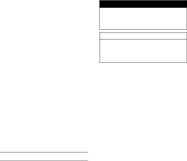
KX125-M1 Left Side View
KX125-M1 Right Side View

1-6 GENERAL INFORMATION
Model Identification
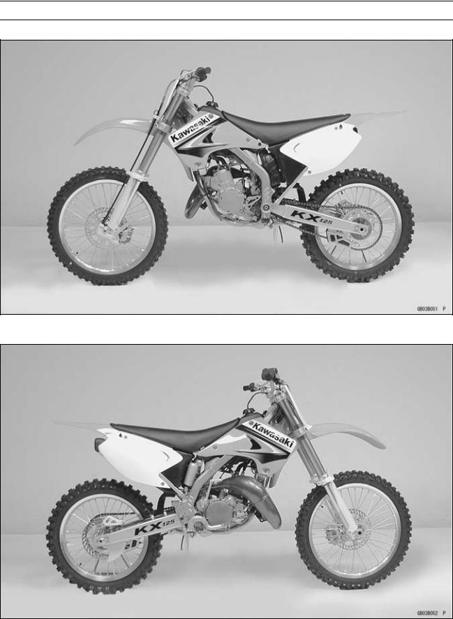
KX250-M1 Left Side View
KX250-M1 Right Side View

GENERAL INFORMATION 1-7
General Specifications
|
Items |
KX125-M1 |
KX125-M2 M3 |
KX125M6F |
|
|
Dimensions |
||||
|
Overall Length |
2 155 mm (84.8 in.) |
2 165 mm (85.2 in.) |
||
|
Overall Width |
825 mm (32.5 in.) |
840 mm (33.1 in.) |
815 mm (32.1 in.) |
|
|
Overall Height |
1 200 mm (47.2 in.) |
1 265 mm (49.8 in.) |
||
|
Wheelbase |
1 455 mm (57.3 in.) |
1 470 mm (57.9 in.) |
||
|
Road Clearance |
340 mm (13.4 in.) |
← |
||
|
Seat Height |
930 mm (36.6 in.) |
940 mm (37.0 in.) |
||
|
Dry Mass |
87 kg (192 lb) |
← |
||
|
Curb Mass: |
||||
|
Front |
45 kg (99 lb) |
← |
||
|
Rear |
47 kg (104 lb) |
← |
||
|
Fuel Tank Capacity |
8.2 L (2.2 US gal) |
← |
||
|
Engine |
||||
|
Type |
2-stroke, single cylinder, |
← |
||
|
crankcase reed valve |
||||
|
Cooling System |
Liquid-cooled |
← |
||
|
Bore and Stroke |
54.0 × 54.5 mm (2.13 × 2.15 in.) |
← |
||
|
Displacement |
124 cm³(7.6 cu in.) |
← |
||
|
Compression Ratio: |
||||
|
Low Speed |
10.6 : 1 |
11.1 : 1 (EUR) 10.9 : 1 |
||
|
High Speed |
8.1 : 1 |
8.5 : 1 (EUR) 8.3 : 1 |
||
|
Carburetion System |
Carburetor, MIKUNI TMX38χ |
← |
||
|
Starting System |
Primary kick |
← |
||
|
Ignition System |
CDI |
← |
||
|
Ignition Timing |
13° BTDC @9 710 r/min (rpm) |
13° BTDC @9 710 r/min (rpm) |
||
|
Spark Plug |
NGK BR9EIX |
NGK R6918B-9 |
NGK BR9ECMVX |
|
|
Port Timing |
||||
|
Inlet: |
||||
|
Open |
Full open |
← |
||
|
Close |
– |
– |
||
|
Scavenging: |
||||
|
Open |
64.9° BBDC |
← |
||
|
Close |
64.9° ABDC |
← |
||
|
Exhaust: |
||||
|
Open |
73.8° BBDC (low speed), |
← |
||
|
95.4° BBDC (high speed) |
← |
|||
|
Close |
73.8° ABDC (low speed), |
← |
||
|
95.4° ABDC (high speed) |
← |
|||
|
Lubrication System |
Petrol mix (32 : 1) |
← |
||
|
(Gasoline : Oil) |
||||
|
Drive Train |
||||
|
Primary Reduction |
||||
|
System: |
||||
|
Type |
Gear |
← |
||
|
Reduction Ratio |
3.200 (64/20) |
← |

1-8 GENERAL INFORMATION
General Specifications
|
Items |
KX125-M1 |
KX125-M2 |
M3 |
KX125M6F |
|
Clutch Type |
Wet, multi disc |
← |
||
|
Transmission: |
||||
|
Type |
6-speed, constant mesh, return |
← |
||
|
shift |
||||
|
Gear Ratios: |
||||
|
1st |
2.384 (31/13) |
← |
||
|
2nd |
1.857 (26/14) |
← |
||
|
3rd |
1.529 (26/17) |
← |
||
|
4th |
1.294 (22/17) |
← |
||
|
5th |
1.125 (27/24) |
← |
||
|
6th |
1.000 (25/25) |
← |
||
|
Final Drive System: |
||||
|
Type |
Chain drive |
← |
||
|
Reduction Ratio |
3.923 (51/13) |
← |
||
|
Overall Drive Ratio |
12.553 @Top gear |
← |
||
|
Transmission Oil: |
||||
|
Grade |
API SE, SF or SG |
← |
API SH, SJ or |
|
|
API SH or SJ with JASO MA |
SL with JASOMA |
|||
|
(KX125M7F ) |
||||
|
Viscosity |
SAE 10W-40 |
← |
||
|
Capacity |
0.7 L (0.74 US qt) |
← |
||
|
Frame |
||||
|
Type |
Tubular, semi-double cradle |
← |
||
|
Steering Angle |
45° to either side |
42° to either side |
||
|
Caster (rake angle) |
27.5° |
27° |
||
|
Trail |
100 mm (3.9 in.) |
113 mm (4.4 in.) |
||
|
Front Tire: |
||||
|
Size |
80/100-21 51M |
← |
||
|
Make/Type |
DUNLOP, Tube type |
← |
||
|
Rear Tire: |
||||
|
Size |
100/90-19 57M |
← |
||
|
Make/Type |
DUNLOP, Tube type |
← |
||
|
Rim Size: |
||||
|
Front |
21 × 1.60 |
← |
||
|
Rear |
19 × 1.85 |
← |
||
|
Front Suspension: |
||||
|
Type |
Telescopic fork (up side down) |
← |
||
|
Wheel Travel |
300 mm (11.8 in.) |
← |
||
|
Rear Suspension: |
||||
|
Type |
Swingarm (Uni-trak) |
Swingarm (New Uni-trak) |
||
|
Wheel Travel |
310 mm (12.2 in.) |
← |
||
|
Brake Type: |
||||
|
Front and Rear |
Single disc |
← |
||

GENERAL INFORMATION 1-9
General Specifications
|
Items |
KX125-M1 |
KX125-M2 |
M3 |
KX125M6F |
|
|
Effective Disc Diameter: |
|||||
|
Front |
220 mm (8.7 in.) |
225 |
mm (8.9 |
in.) |
|
|
Rear |
200 mm (7.9 in.) |
215 |
mm (8.5 |
in.) |
Specifications are subject to change without notice, and may not apply to every country. (EUR): Europe Model

1-10 GENERAL INFORMATION
General Specifications
|
Items |
KX250-M1 |
KX250-M2 |
|
|
Dimensions |
|||
|
Overall Length |
2 175 mm (85.6 in.) |
← |
|
|
Overall Width |
825 mm (32.5 in.) |
840 mm (33.1 in.) |
|
|
Overall Height |
1 205 mm (47.4 in.) |
1 265 mm (49.8 in.) |
|
|
Wheelbase |
1 480 mm (58.3 in.) |
← |
|
|
Road Clearance |
355 mm (14.0 in.) |
340 mm (13.4 in.) |
|
|
Seat Height |
945 mm (37.2 in.) |
← |
|
|
Dry Mass |
97 kg (214 lb) |
← |
|
|
Curb Mass: |
|||
|
Front |
50 kg (110 lb) |
← |
|
|
Rear |
51 kg (112 lb) |
← |
|
|
Fuel tank Capacity |
8.2 L (2.2 US gal) |
← |
|
|
Engine |
|||
|
Type |
2-stroke, single cylinder, piston |
← |
|
|
reed valve |
|||
|
Cooling System |
Liquid-cooled |
← |
|
|
Bore and Stroke |
66.4 × 72.0 mm (2.61 × 2.85 in.) |
← |
|
|
Displacement |
249 cm³ (15.25 cu in.) |
← |
|
|
Compression Ratio |
|||
|
Low Speed |
10.1 : 1 |
10.5 : |
1 |
|
High Speed |
8.6 : 1 |
8.8 : |
1 |
|
Carburetion System |
Carburetor, KEIHIN PWK38S |
← |
|
|
Starting System |
Primary kick |
← |
|
|
Ignition System |
CDI |
← |
|
|
Ignition Timing |
14° BTDC @7 740 r/min (rpm) |
← |
|
|
Spark Plug |
NGK BR8EIX |
← |
|
|
Port Timing: |
|||
|
Inlet: |
|||
|
Open |
Full open |
← |
|
|
Close |
– |
– |
|
|
Scavenging: |
|||
|
Open |
57.6° BBDC |
59.3° BBDC |
|
|
Close |
57.6° ABDC |
59.3° ABDC |
|
|
Exhaust: |
|||
|
Open |
78.1° BBDC (low speed), |
78.4° BBDC (low speed), |
|
|
91.4° BBDC (high speed) |
92.2° BBDC (high speed) |
||
|
Close |
78.1° ABDC (low speed), |
78.4° ABDC (low speed), |
|
|
91.4° ABDC (high speed) |
92.2° ABDC (high speed) |
||
|
Lubrication System (Gasoline: Oil) |
Petrol mix (32 : 1) |
← |
|
|
Drive Train |
|||
|
Primary Reduction System: |
|||
|
Type |
Gear |
← |
|
|
Reduction ratio |
3.000 (63/21) |
← |
|
|
Clutch Type |
Wet, multi disc |
← |

GENERAL INFORMATION 1-11
General Specifications
|
Items |
KX250-M1 |
KX250-M2 |
|
|
Transmission: |
|||
|
Type |
5 speed, constant mesh, return |
← |
|
|
shift |
|||
|
Gear Ratios: |
|||
|
1st |
1.800 (27/15) |
← |
|
|
2nd |
1.437 (23/16) |
← |
|
|
3rd |
1.176 (20/17) |
← |
|
|
4th |
1.000 (21/21) |
← |
|
|
5th |
0.869 (20/23) |
← |
|
|
Final Drive System |
|||
|
Type |
Chain drive |
← |
|
|
Reduction Ratio |
3.769 (49/13) |
← |
|
|
Overall Drive Ratio |
9.832 @Top gear |
← |
|
|
Transmission Oil: |
|||
|
Grade |
API SE, SF or SG |
← |
|
|
API SH or SJ with JASO MA |
← |
||
|
Viscosity |
SAE 10W-40 |
← |
|
|
Capacity |
0.85 L (0.90 US qt) |
← |
|
|
Frame |
|||
|
Type |
Tubular, semi-double cradle |
← |
|
|
Steering Angle |
45° to either side |
42° to either side |
|
|
Caster (rake angle) |
27° |
← |
|
|
Trail |
97 mm (3.8 in.) |
112 mm (4.4 in.) |
|
|
Front Tire: |
|||
|
Size |
80/100-21 51M |
← |
|
|
Make/Type |
BRIDGESTONE, Tube type |
← |
|
|
(EUR) DUNLOP, Tube type |
← |
||
|
Rear Tire: |
|||
|
Size |
110/90-19 62M |
← |
|
|
Make/Type |
BRIDGESTONE, Tube type |
← |
|
|
(EUR) DUNLOP, Tube type |
← |
||
|
Rim Size: |
|||
|
Front |
21 × 1.60 |
← |
|
|
Rear |
19 × 2.15 |
← |
|
|
Front Suspension: |
|||
|
Type |
Telescopic fork (up side down) |
← |
|
|
Wheel Travel |
300 mm (11.8 in.) |
← |
|
|
Rear Suspension: |
|||
|
Type |
Swingarm (Uni-trak) |
Swingarm (New Uni-trak) |
|
|
Wheel Travel |
310 mm (12.2 in.) |
← |
|
|
Brake Type: |
|||
|
Front and Rear |
Single disc |
← |
|

1-12 GENERAL INFORMATION
General Specifications
|
Items |
KX250-M1 |
KX250-M2 |
|
Effective Disc Diameter: |
||
|
Front |
220 mm (8.7 in.) |
225 mm (8.9 in.) |
|
Rear |
200 mm (7.9 in.) |
215 mm (8.5 in.) |
Specifications are subject to change without notice, and may not apply to every country. (EUR): Europe Model
![]()
GENERAL INFORMATION 1-13
Technical Information
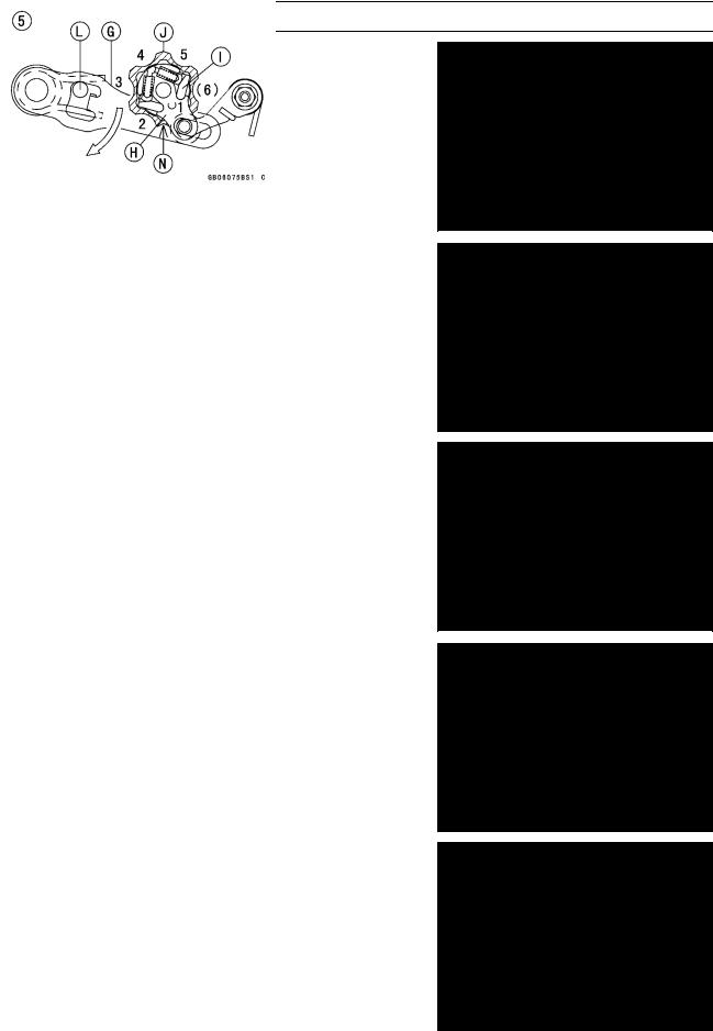
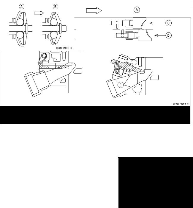
Ratchet-Type Shift Mechanism (KX250M, KX125M)
○The shift mechanism of the KX250M (5-speed) is shown in the following figure.
○This mechanism is stronger and simpler than the usual slide type and enables light and positive shifting. When the shift pedal [D] is applied, its turning force is transmitted almost directly to the shift drum [E].
○The mechanism has shorter length between the shift drum and the drive shaft, compared with the previous model (for example, from 67 mm to 43.2 mm for KX125).
○The shift force is transmitted as follows:
Shift Pedal → Shift Shaft [F] → Shift Mechanism Arm [G] → Ratchet [H] → Pawls [I], [M] in Ratchet → Shift Drum Cam [J] → Shift Forks → Gears
|
A. Top View |
F. Top View |
K. Gear Set Lever |
|
B. Front |
G. Shift Mechanism Arm |
L. Return Spring Pin |
|
C. Ratchet Plate |
H. Ratchet |
M. Lower Pawl |
|
D. Shift Pedal |
I. Upper Pawls |
N. Neutral Detent |
|
E. Shift Drum |
J. Shift Drum Cam |
O. Return Spring |
1-14 GENERAL INFORMATION
Technical Information
○This mechanism operates as follows:
1.Suppose the 1st gear position is set as shown. Neutral Detent [N]
2.Shift Up (for example: shift from 1st to 2nd) (→) : transmitting of shift force
The shift pedal is lifted. → The arm [G] turns counterclockwise until it stops at pin [L]. → ratchet [H] → lower pawl [M] → shift drum cam [J] → shift drum → The gear is shifted in 2nd position.
3.Ratchet Returns.
The arm [G] returns by force of spring [O]. →The ratchet
[H]disengages to be free by itself. → The set lever [K] holds the shift drum cam [J]. → The ratchet [H] returns (turns clockwise).
4.The 2nd Gear Position settles.
The upper and lower pawls [I], [M] catch the next teeth inside the shift drum cam [J] → The ratchet [H] settles in position. → The 2nd gear position settles.
5.Shift Down (for example: shift from 2nd to 1st)
The shift pedal is depressed. →The arm [G] turns clockwise until it stops at the pin [L]. → ratchet [H] → upper pawl [I] → shift drum cam [J] → shift drum → The gear is shifted into 1st position. → (continues to operate in the same way as Shift Up)
GENERAL INFORMATION 1-15
Technical Information
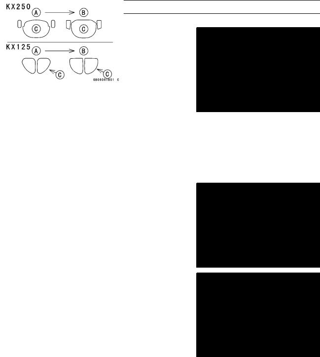
Chrome Composite Plating Cylinder (KX250M, KX125M)
○This new cylinder bore [A] has Kawasaki’s composite cylinder plating, which is used for the first time on two stroke engines. The composite plating includes a nickel-phosphorous alloy, inorganic materials like ceramic, silicone carbide and some organic materials.
○The treatment improves heat transfer of the cylinder for consistent power output, allows closer piston-to-cylinder clearances for more horsepower.
○The treatment is porous, so it holds lubrication well, and hard, so it resists abrasion and seizure.
○This plating gets on well even the chamfered edge of the cylinder top or port.
○This improves the surface of the chamber at the top of the cylinder, preventing hot spots, resultant pre-ignition and other abnormal combustion in the chamber.
Previous Cylinder [A] New Cylinder [B] Exhaust Port [C] Cylinder Top [D]
○This enables the top end of the exhaust port from round to straight in order to make gas flow smooth and improve mid-high performance and extending piston ring life.
Previous Cylinder [A] New Cylinder [B] Exhaust Port [C]
1-16 GENERAL INFORMATION
Technical Information
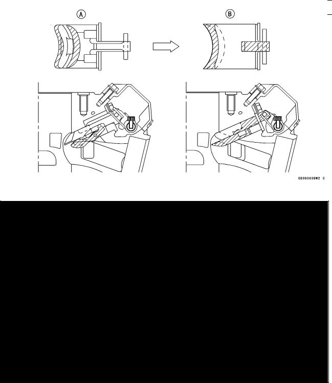
KIPS (Kawasaki Integrated Power Valve System, KX250M, KX125M)
○KIPS varies the exhaust port height to broaden the useful rpm range for low end and mid-range without sacrificing the top end power (see ’95 KDX200H Service Manual (Part No. 99924-1181-01) for basic information about KIPS).
○KIPS is 2-stage-3-way type: the main exhaust port is opened earlier than the sub-exhaust ports (2-stage) and they are opened differently in low, middle and high rpm (3-way).
(In low rpm)
resonator: open to fully, sub-exhaust ports and main exhaust port: close (In middle rpm)
resonator: close, main exhaust port: open to fully, sub-exhaust ports open to halfway (In high rpm)
resonator: close, main exhaust port and sub-exhaust ports open fully. ○The KIPS valve is now made of aluminum instead of steel to save weight.
○The KIPS main valve holder shape is modified to match the straightened exhaust port, and timing for the main and sub-valves is changed to deliver more power in the low to mid-range.
○The main valve end is changed from thick end to thin end, reducing exhaust pressure on the valve and making valve operation smooth.
(KX250M)
A.Previous KIPS
B.New KIPS
GENERAL INFORMATION 1-17
Technical Information
(KX125M)
A.Previous KIPS
B.New Model
C.Full Opened Position
D.Low Speed Position
E.Straightened Exhaust Passage
○The KIPS governor is modified so that the exhaust valves operate over a wider rpm range to improve low and mid -range power and smooth the power delivery.
○The KX250’s governor inside is changed from straight to concave in order to move the balls smoothly.
Previous Governor [A] New Governor [B]
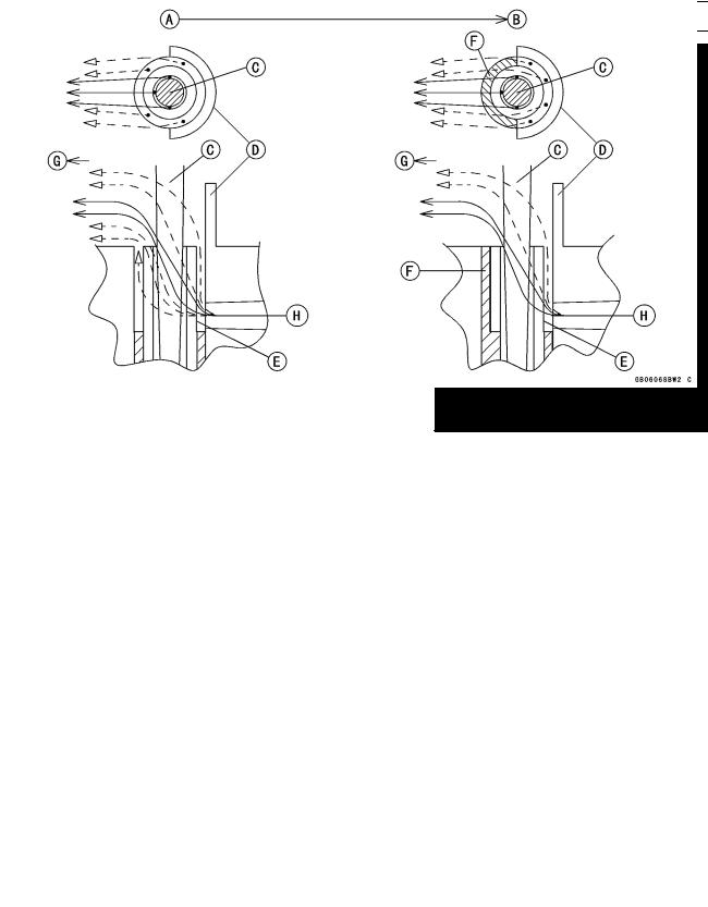
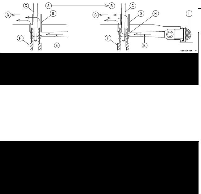
Carburetor (KX250M)
○The 38.7 mm (1.524 in.) Keihin PWK 38S carburetor helps boost mid-range and top-end power.
1-18 GENERAL INFORMATION
Technical Information
○The crescent shaped slide [A] enables the needle to sit closer to the intake ports for quicker throttle response.
○Large bores in the front and back of the carburetor and a smoother shape (38 to 40 mm-tapered bore [B]) boost mixture flow for more mid-range and top-end power.
○The semi air bleed needle jet [C] improves throttle response in the very low and low range.
Front [D]
○The air baffle forms vacuum, the stop narrows the outlet and speeds up outflow from the needle jet, improving atomization.
|
←—: |
Fuel Droplets |
||
|
← — -: |
Fuel Mist |
||
|
A. Previous Carburetor |
E. Needle Jet |
||
|
B. New Carburetor |
F. Stop |
||
|
C. Jet Needle |
G. Engine Inlet |
||
|
D. Air Baffle |
H. Main Air |
○The new main air inlet tends to take in static pressure and to exclude dynamic pressure and vortexes, making the main air flow stable.
GENERAL INFORMATION 1-19
Technical Information
A.Previous Carburetor
B.New Carburetor
C.Jet Needle
D.Air Baffle
E.Main Air
F.Needle Jet
G.Engine Inlet
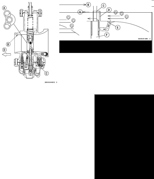
Carburetor (KX125M)
○The 38 mm (1.496 in.) Mikuni TMX 38-27 carburetor helps boost mid-range and top-end power.
○The arched slide [A] improves throttle response in the very low and low ranges.
○Large bores in the front and back of the carburetor and a smoother shape (38 to 40 mm-tapered bore [B]) boost mixture flow for more mid-range and top-end power.
○The semi air bleed needle jet [C] improves throttle response in the low range and provides proper mixture from the low to top range.
Front [D]
1-20 GENERAL INFORMATION
Technical Information
○In low range, fuel drops in the fuel/air mixture is larger and tends to stick to the carburetor wall. The arched slide deflects fuel/air mixture flow from the wall to the middle of the carburetor for better atomization and better throttle response.
A.Previous Carburetor
B.New Carburetor
C.Flat Slide (piston valve)
D.Arched Shape Slide (piston valve)
E.Engine Intake
○The semi air bleed hole is positioned at the side of the needle jet, where fuel mixes with air well (due to enough fuel and faster air flow than in main bore), resulting in better atomizing. The air screen suppresses dynamic pressure around the main air inlet.
A.Previous Carburetor
B.New Carburetor
C.Jet Needle
D.Air Baffle
E.Main Air
F.Needle Jet
G.Engine Intake
H.Semi Air Bleed Hole
I.Air Screen

GENERAL INFORMATION 1-21
Unit Conversion Table
Prefixes for Units: |
Units of Length: |
|
Prefix |
Symbol |
Power |
||
|
mega |
M |
× 1 000 |
000 |
|
|
kilo |
k |
× |
1 000 |
|
|
centi |
c |
× |
0.01 |
|
|
milli |
m |
× |
0.001 |
|
|
micro |
µ |
× 0.000001 |
Units of Mass:
|
kg |
× |
2.205 |
= |
lb |
|
g |
× |
0.03527 |
= |
oz |
Units of Volume:
|
L |
× |
0.2642 |
= |
gal (US) |
|
L |
× |
0.2200 |
= |
gal (imp) |
|
L |
× |
1.057 |
= |
qt (US) |
|
L |
× |
0.8799 |
= |
qt (imp) |
|
L |
× |
2.113 |
= |
pint (US) |
|
L |
× |
1.816 |
= |
pint (imp) |
|
mL |
× |
0.03381 |
= |
oz (US) |
|
mL |
× |
0.02816 |
= |
oz (imp) |
|
mL |
× |
0.06102 |
= |
cu in |
Units of Force:
|
N |
× |
0.1020 |
= |
kgf |
|
N |
× |
0.2248 |
= |
lb |
|
kgf |
× |
9.807 |
= |
N |
|
kgf |
× |
2.205 |
= |
lb |
|
km |
× |
0.6214 |
= |
mile |
|
m |
× |
3.281 |
= |
ft |
|
mm |
× |
0.03937 |
= |
in |
Units of Torque:
|
N·m |
× |
0.1020 |
= |
kgf·m |
|
N·m |
× |
0.7376 |
= |
ft·lb |
|
N·m |
× |
8.851 |
= |
in·lb |
|
kgf·m |
× |
9.807 |
= |
N·m |
|
kgf·m |
× |
7.233 |
= |
ft·lb |
|
kgf·m |
× |
86.80 |
= |
in·lb |
Units of Pressure:
|
kPa |
× |
0.01020 |
= |
kgf/cm² |
|
kPa |
× |
0.1450 |
= |
psi |
|
kPa |
× |
0.7501 |
= |
cm Hg |
|
kgf/cm² |
× |
98.07 |
= |
kPa |
|
kgf/cm² |
× |
14.22 |
= |
psi |
|
cm Hg |
× |
1.333 |
= |
kPa |
Units of Speed:
km/h × 0.6214 = mph
Units of Power:
|
kW |
× |
1.360 |
= |
PS |
|
kW |
× |
1.341 |
= |
HP |
|
PS |
× |
0.7355 |
= |
kW |
|
PS |
× |
0.9863 |
= |
HP |
Units of Temperature:
![]()
PERIODIC MAINTENANCE 2-1
Periodic Maintenance
|
Table of Contents |
2 |
||
|
Periodic Maintenance Chart ……………………………………………………………………………………… |
2-3 |
||
|
Torque and Locking Agent………………………………………………………………………………………… |
2-5 |
||
|
Specifications …………………………………………………………………………………………………………. |
2-10 |
||
|
Special Tools ………………………………………………………………………………………………………….. |
2-13 |
||
|
Periodic Maintenance Procedures……………………………………………………………………………… |
2-14 |
||
|
Fuel System…………………………………………………………………………………………………………. |
2-14 |
||
|
Fuel Hose and Connections Inspection …………………………………………………………………. |
2-14 |
||
|
Throttle Cable Inspection …………………………………………………………………………………….. |
2-14 |
||
|
Carburetor Inspection …………………………………………………………………………………………. |
2-15 |
||
|
Air Cleaner Element Cleaning and Inspection ………………………………………………………… |
2-15 |
||
|
Fuel Tank and Tap Cleaning ………………………………………………………………………………… |
2-16 |
||
|
Cooling System…………………………………………………………………………………………………….. |
2-16 |
||
|
Coolant Inspection ……………………………………………………………………………………………… |
2-17 |
||
|
Water Hoses and Connections Inspection……………………………………………………………… |
2-19 |
||
|
Engine Top End ……………………………………………………………………………………………………. |
2-19 |
||
|
Cylinder Head Warp Inspection ……………………………………………………………………………. |
2-19 |
||
|
Cylinder Wear Inspection…………………………………………………………………………………….. |
2-20 |
||
|
Piston Diameter Measurement …………………………………………………………………………….. |
2-20 |
||
|
Piston/Cylinder Clearance Inspection ……………………………………………………………………. |
2-21 |
||
|
Piston Ring, Piston Ring Groove Inspection …………………………………………………………… |
2-22 |
||
|
Piston Ring End Gap Inspection …………………………………………………………………………… |
2-23 |
||
|
Piston, Piston Pin, Connecting Rod Wear Inspection ………………………………………………. |
2-23 |
||
|
Exhaust Valve Cleaning and Inspection…………………………………………………………………. |
2-24 |
||
|
Exhaust System Inspection………………………………………………………………………………….. |
2-24 |
||
|
Muffler Cleaning and Inspection …………………………………………………………………………… |
2-24 |
||
|
Muffler Baffle Change …………………………………………………………………………………………. |
2-25 |
||
|
Engine Right Side…………………………………………………………………………………………………. |
2-25 |
||
|
Clutch Inspection ……………………………………………………………………………………………….. |
2-25 |
||
|
Clutch Plates Inspection ……………………………………………………………………………………… |
2-26 |
||
|
Engine Bottom End/Transmission …………………………………………………………………………… |
2-27 |
||
|
Transmission Oil Change…………………………………………………………………………………….. |
2-27 |
||
|
Wheels/Tires………………………………………………………………………………………………………… |
2-28 |
||
|
Tire Air Pressure Inspection/Adjustment………………………………………………………………… |
2-28 |
||
|
Tires Inspection………………………………………………………………………………………………….. |
2-29 |
||
|
Spoke Tightness Inspection…………………………………………………………………………………. |
2-30 |
||
|
Rim Runout Inspection………………………………………………………………………………………… |
2-30 |
||
|
Wheel Bearing Inspection ……………………………………………………………………………………. |
2-30 |
||
|
Final Drive……………………………………………………………………………………………………………. |
2-31 |
||
|
Drive Chain Inspection………………………………………………………………………………………… |
2-31 |
||
|
Drive Chain Wear Inspection ……………………………………………………………………………….. |
2-32 |
||
|
Drive Chain Lubrication……………………………………………………………………………………….. |
2-33 |
||
|
Sprockets Inspection…………………………………………………………………………………………… |
2-33 |
||
|
Rear Sprocket Warp (Runout) Inspection ………………………………………………………………. |
2-34 |
||
|
Brakes…………………………………………………………………………………………………………………. |
2-34 |
||
|
Brake Lever Play Adjustment……………………………………………………………………………….. |
2-34 |
||
|
Brake Fluid Level Inspection………………………………………………………………………………… |
2-35 |

2-2 PERIODIC MAINTENANCE
|
Brake Fluid Change ……………………………………………………………………………………………. |
2-36 |
|
Brake Pad Wear Inspection …………………………………………………………………………………. |
2-37 |
|
Brake Master Cylinder Cup and Dust Seal Replacement …………………………………………. |
2-37 |
|
Brake Caliper Fluid Seal and Dust Seal Replacement …………………………………………….. |
2-37 |
|
Brake Hoses and Connections Inspection ……………………………………………………………… |
2-38 |
|
Brake Hose Replacement ……………………………………………………………………………………. |
2-38 |
|
Suspension………………………………………………………………………………………………………….. |
2-39 |
|
Front Fork Inspection ………………………………………………………………………………………….. |
2-39 |
|
Front Fork Oil Change/Oil Level Adjustment (each fork leg) …………………………………….. |
2-40 |
|
Rear Shock Absorber Oil Change…………………………………………………………………………. |
2-42 |
|
Swingarm and Uni-Trak Linkage Inspection …………………………………………………………… |
2-42 |
|
Swingarm and Uni-Trak Linkage Pivot Lubrication ………………………………………………….. |
2-42 |
|
Chain Guide Wear Inspection ………………………………………………………………………………. |
2-43 |
|
Chain Slipper Wear Inspection …………………………………………………………………………….. |
2-43 |
|
Steering ………………………………………………………………………………………………………………. |
2-43 |
|
Steering Inspection …………………………………………………………………………………………….. |
2-43 |
|
Steering Stem Bearing Lubrication ……………………………………………………………………….. |
2-46 |
|
Frame …………………………………………………………………………………………………………………. |
2-46 |
|
Frame Inspection ……………………………………………………………………………………………….. |
2-46 |
|
Electrical System ………………………………………………………………………………………………….. |
2-47 |
|
Spark Plug Cleaning and Inspection……………………………………………………………………… |
2-47 |
|
Spark Plug Gap Inspection ………………………………………………………………………………….. |
2-47 |
|
General Lubrication ………………………………………………………………………………………………. |
2-48 |
|
Lubrication ………………………………………………………………………………………………………… |
2-48 |
|
Nut, Bolt, and Fastener Tightness …………………………………………………………………………… |
2-49 |
|
Tightness Inspection …………………………………………………………………………………………… |
2-49 |

PERIODIC MAINTENANCE 2-3
Periodic Maintenance Chart
The maintenance must be done in accordance with this chart to keep the motorcycle in good running condition.
|
FREQUENCY |
After |
Every |
Every |
Every |
||||
|
each |
3 races |
5 races |
10 |
As re- |
See |
|||
|
race or |
or 7.5 |
or 12.5 |
races |
quired |
Page |
|||
|
OPERATION |
2.5 hr |
hr |
hr |
or 25 hr |
||||
|
Spark plug — clean and inspect † |
• |
R |
2-47 |
|||||
|
Clutch — inspect |
• |
2-25 |
||||||
|
E |
Clutch plates — inspect † |
• |
R |
2-26 |
||||
|
Throttle cable — inspect |
• |
2-14 |
||||||
|
Air cleaner element — clean and inspect |
• |
2-15 |
||||||
|
N |
Air cleaner element — replace |
If damaged |
2-15 |
|||||
|
Carburetor — inspect |
• |
2-15 |
||||||
|
Transmission oil — change |
• |
2-27 |
||||||
|
G |
Piston and piston ring — clean and inspect† |
• |
R |
2-20 |
||||
|
Cylinder head, cylinder — inspect |
• |
2-19 |
||||||
|
Connecting rodinspect † |
• |
R |
2-23 |
|||||
|
Exhaust valve — clean and inspect |
• |
2-24 |
||||||
|
Exhaust system — inspect |
• |
2-24 |
||||||
|
N |
Muffler — clean and inspect † |
• |
2-24 |
|||||
|
Muffler baffle — change |
• |
2-25 |
||||||
|
Kick pedal and shift pedal — clean |
• |
– |
||||||
|
E |
Sprockets — inspect † |
• |
2-34 |
|||||
|
Coolant — inspect † |
• |
R |
2-17 |
|||||
|
Water hoses and connections — inspect † |
• |
2-19 |
||||||
|
Brake adjustment — inspect † |
• |
2-34 |
||||||
|
C |
Brake pad wear — inspect † |
• |
2-37 |
|||||
|
Brake fluid level — inspect † |
• |
2-35 |
||||||
|
H |
Brake fluid — change |
Every 2 years |
2-36 |
|||||
|
Brake master cylinder cup and dust cover — |
Every 2 years |
2-37 |
||||||
|
A |
replace |
|||||||
|
Brake caliper fluid seal and dust seal — |
Every 2 years |
2-37 |
||||||
|
replace |
||||||||
|
S |
Brake hoses and pipe — replace |
Every 4 years |
2-38 |
|||||
|
Brake hoses, connections — inspect † |
• |
2-38 |
||||||
|
S |
Spoke tightness and rim runout — inspect † |
• |
2-30 |
|||||
|
Wheel bearing — inspect † |
• |
2-30 |
||||||
|
I |
Drive chain — inspect |
• |
2-31 |
|||||
|
Drive chain — lubricate |
• |
2-33 |
||||||
|
S |
Drive chain wear — inspect † |
• |
2-32 |
|||||
|
Chain slipper and guide — replace |
If damaged |
2-43 |
||||||
|
Rear sprocket warp (runout) — inspect † |
• |
2-34 |
||||||
|
Front fork — inspect and clean |
• |
2-39 |
||||||

2-4 PERIODIC MAINTENANCE
Periodic Maintenance Chart
|
FREQUENCY |
After |
Every |
Every |
Every |
As re- |
See |
|
|
each |
3 races |
5 races |
10 |
||||
|
race or |
or 7.5 |
or 12.5 |
races |
quired |
Page |
||
|
OPERATION |
2.5 hr |
hr |
hr |
or 25 hr |
|||
|
Front fork oil — change |
1st time after 2 races, then every 5 races |
2-40 |
|||||
|
Rear shock absorber oil — change |
1st time after 2 races, then every 5 races |
2-42 |
|||||
|
C |
Fuel Tank and Tap — clean |
• |
2-16 |
||||
|
H |
Fuel hose — replace |
Every 4 years |
2-14 |
||||
|
A |
Fuel hose, connections — inspect † |
• |
2-14 |
||||
|
S |
Steering — inspect † |
• |
2-43 |
||||
|
S |
Steering stem bearing — lubricate |
• |
2-46 |
||||
|
I |
Swingarm and Uni-Trak linkage pivots — |
• |
2-42 |
||||
|
lubricate |
|||||||
|
S |
Swingarm and Uni-Trak linkage — inspect † |
• |
2-42 |
||||
|
Wheel/tire (air pressure, excessive wear or |
• |
2-28 |
|||||
|
damage) — inspect |
|||||||
|
Frame — clean and inspect |
• |
2-46 |
|||||
|
Nuts, bolts, and fasteners tightnessinspect † |
• |
2-49 |
|||||
|
General lubrication — perform |
• |
2-48 |
†: Replace, add, adjust, clean or torque if necessary. R: Replace

PERIODIC MAINTENANCE 2-5
Torque and Locking Agent
Tighten all bolts and nuts to the proper torque using an accurate torque wrench. If insufficiently tightened, a bolt or nut may become damaged, strip an internal thread, or break and then fall out. The following table lists the tightening toque for the major bolts and nuts, and the parts requiring use of a non-permanent locking agent or liquid gasket.
When checking the tightening toque of the bolts and nuts, first loosen the bolt or nut by half a turn and then tighten to specified torque.
Letters used in the “Remarks” column mean:
L : Apply a non-permanent locking agent to the threads. LG : Apply liquid gasket to the threads.
S : Tighten the fasteners following the specified sequence.
|
Fastener |
Torque |
Remarks |
||||
|
N·m |
kgf·m |
ft·lb |
||||
|
Fuel System |
||||||
|
Carburetor Holder Mounting Bolts |
8.8 |
0.9 |
78 in·lb |
|||
|
Carburetor Holding Clamp Screw |
1.5 |
0.15 |
13 in·lb |
|||
|
Reed Valve Screws |
1.0 |
0.1 |
9 in·lb |
|||
|
Carburetor Top Cover Screws (KX125) |
3.0 |
0.3 |
26 in·lb |
|||
|
Carburetor Top Cover Allen Bolts (KX250) |
35 in·lb |
|||||
|
3.9 |
0.4 |
|||||
|
Throttle Sensor Bolt (KX250) |
2.0 |
0.2 |
17 in·lb |
|||
|
Rear Frame Mounting Bolts |
34 |
3.5 |
25 |
|||
|
Air Cleaner Duct Clamp Screw |
1.5 |
0.15 |
13 in·lb |
|||
|
Fuel Tap Plate Mounting Screws |
0.8 |
0.08 |
7 in·lb |
|||
|
Air Cleaner Duct Nuts |
3.0 |
0.3 |
26 in·lb |
|||
|
Air Cleaner Housing Bolts |
8.8 |
0.9 |
78 in·lb |
|||
|
Cooling System |
||||||
|
Water Pump Cover Bolts |
8.8 |
0.9 |
78 in·lb |
|||
|
Water Pump Impeller Bolt |
6.9 |
0.7 |
61 in·lb |
|||
|
Water Hose Clamp Screws |
1.5 |
0.15 |
13 in·lb |
|||
|
Coolant Drain Bolt (Water Pump Cover) |
8.8 |
0.9 |
78 in·lb |
|||
|
Coolant Drain Bolt (Cylinder) (KX250) |
8.8 |
0.9 |
78 in·lb |
|||
|
Water Hose Elbow Fitting Bolts (Cylinder) (KX250) |
8.8 |
0.9 |
78 in·lb |
|||
|
Water Pump Cover Fitting Bolts (KX250) |
5.9 |
0.6 |
52 in·lb |
|||
|
Radiator Shroud Bolts |
8.8 |
0.9 |
78 in·lb |
|||
|
Radiator Mounting Bolts |
8.8 |
0.9 |
78 in·lb |
|||
|
Radiator Screen Bolts |
8.8 |
0.9 |
78 in·lb |
|||
|
Radiator Bracket Bolts |
8.8 |
0.9 |
78 in·lb |
|||
|
Engine Top End |
||||||
|
Main Valve Cover Bolts |
5.9 |
0.6 |
52 in·lb |
|||
|
Cylinder Head Nuts |
25 |
2.5 |
18 |
S |
||
|
Spark Plug |
27 |
2.8 |
20 |
|||
|
Engine Mounting Bracket Nuts: |
||||||
|
Engine Side 10 mm (KX125/250-M1) |
44 |
4.5 |
33 |
|||
|
Engine Side 10 mm (KX125/250-M2 ) |
49 |
5.0 |
36 |
|||
|
Frame Side 8 m |
29 |
3.0 |
22 |
|||

2-6 PERIODIC MAINTENANCE
Torque and Locking Agent
|
Fastener |
Torque |
Remarks |
||||
|
N·m |
kgf·m |
ft·lb |
||||
|
KIPS Cover Bolts: |
||||||
|
KX125-M1 |
4.9 |
0.5 |
43 in·lb |
|||
|
KX125-M2 |
8.8 |
0.9 |
78 in·lb |
|||
|
KX250 |
2.9 |
0.3 |
26 in·lb |
|||
|
Cylinder Nuts: |
||||||
|
KX125 |
25 |
2.5 |
18 |
|||
|
KX250 |
34 |
3.5 |
25 |
|||
|
Cylinder Left Cover Bolts (KX250) |
52 in·lb |
|||||
|
5.9 |
0.6 |
|||||
|
Main Lever Mounting Allen Bolt |
3.9 |
0.4 |
35 in·lb |
L |
||
|
Governor Shaft Lever Mounting Bolt (KX125) |
6.9 |
0.7 |
61 in·lb |
|||
|
Exhaust Valve Retaining Bolts (KX125) |
5.9 |
0.6 |
52 in·lb |
|||
|
Main Shaft Stopper Pin Plug (KX125) |
0.8 |
0.08 |
7 in·lb |
|||
|
Main Valve Retaining Bolts (KX250) |
5.9 |
0.6 |
52 in·lb |
|||
|
Operating Rod Retaining Screw (KX250) |
5.4 |
0.55 |
48 in·lb |
|||
|
Operating Rod Left Side Plug (KX250) |
22 |
2.2 |
16 |
|||
|
Main Valve Rod Cover Screw (KX250) |
5.9 |
0.6 |
52 in·lb |
|||
|
Coolant Drain Plug (Cylinder) (KX250) |
8.8 |
0.9 |
78 in·lb |
|||
|
Inner Pipe Mounting Bolts |
8.8 |
0.9 |
78 in·lb |
L |
||
|
Muffler Pipe Mounting Bolts |
8.8 |
0.9 |
78 in·lb |
L |
||
|
Muffler Damper Mounting Bolts (KX125/250-M2 ) |
8.8 |
0.9 |
78 in·lb |
|||
|
Expansion Chamber Mounting Bolt (KX125/250-M2 ) |
12 |
1.2 |
104in·lb |
|||
|
Muffler Mounting Bolt |
8.8 |
0.9 |
78 in·lb |
|||
|
Engine Right Side |
||||||
|
Clutch Hub Nut |
98 |
10.0 |
72 |
|||
|
Clutch Spring Bolts |
8.8 |
0.9 |
78 in·lb |
|||
|
Clutch Cover Bolts |
8.8 |
0.9 |
78 in·lb |
|||
|
Governor Shaft Lever Positioning Plug |
0.6 |
0.06 |
5 in·lb |
|||
|
Oil Filler Cap |
1.5 |
0.15 |
13 in·lb |
|||
|
Right Engine Cover Bolts |
8.8 |
0.9 |
78 in·lb |
|||
|
Governer Shaft Lever Mounting Bolt (KX125) |
6.9 |
0.7 |
61 in·lb |
|||
|
Exhaust Valve Advancer Lever Mounting Allen Bolts |
3.9 |
0.4 |
35 in·lb |
L |
||
|
Primary Gear Nut (KX125) |
59 |
6.0 |
43 |
|||
|
Gear Set Lever Nut |
8.8 |
0.9 |
78 in·lb |
|||
|
Ratchet Plate Mounting Bolts |
8.8 |
0.9 |
78 in·lb |
|||
|
Kick Ratchet Guide Bolt |
8.8 |
0.9 |
78 in·lb |
|||
|
Kick Pedal Bolt: |
||||||
|
KX125 |
12 |
1.2 |
104 in·lb |
|||
|
KX250 |
25 |
2.5 |
18 |
|||
|
Shift Pedal Bolt |
9.8 |
1.0 |
87 in·lb |
|||
|
External Shift Mechanism Return Spring Pin (KX250) |
42 |
4.3 |
31 |
L |
||
|
Gear Set Lever Pivot Stud |
– |
– |
– |
L (Planted |
||
|
Side) |
||||||

PERIODIC MAINTENANCE 2-7
Torque and Locking Agent
|
Fastener |
Torque |
Remarks |
|||
|
N·m |
kgf·m |
ft·lb |
|||
|
Engine Removal/Installation |
|||||
|
Engine Mounting Nuts: |
|||||
|
KX125/250-M1 |
44 |
4.5 |
33 |
||
|
KX125/250-M2 |
49 |
5.0 |
36 |
||
|
Engine Mounting Bracket Nuts: |
|||||
|
Engine Side 10 mm (KX125/250-M1) |
44 |
4.5 |
33 |
||
|
Engine Side 10 mm (KX125/250-M2 ) |
49 |
5.0 |
36 |
||
|
Frame Side 8 mm |
29 |
3.0 |
22 |
||
|
Swingarm Pivot Shaft Nut |
98 |
10.0 |
72 |
||
|
Engine Bottom End/Transmission |
|||||
|
Output Shaft Bearing Retaining Screws |
5.4 |
0.55 |
48 in·lb |
L |
|
|
Shift Drum Bearing Retaining Screws (KX125-M1) |
6.4 |
0.65 |
56 in·lb |
L |
|
|
Shift Drum Bearing Retaining Bolts (KX125-M2 ) |
8.8 |
0.9 |
78 in·lb |
L |
|
|
Shift Drum Bearing Retaining Bolts (KX250) |
8.8 |
0.9 |
78 in·lb |
L |
|
|
Drive Shaft Bearing Retaining Bolts (KX250) |
8.8 |
0.9 |
78 in·lb |
||
|
Engine Oil Drain Bolt |
20 |
2.0 |
14.5 |
||
|
Crankcase Bolts |
8.8 |
0.9 |
78 in·lb |
||
|
Flywheel Bolt (KX125) |
22 |
2.2 |
16 |
||
|
Flywheel Nut (KX250) |
78 |
8.0 |
58 |
||
|
Shift Drum Operating Cam Bolt |
24 |
2.4 |
17 |
L |
|
|
Cylinder Stud |
– |
– |
– |
L (Planted |
|
|
Side) |
|||||
|
Wheels/Tires |
|||||
|
Front Axle Nut |
78 |
8.0 |
58 |
||
|
Front Axle Clamp Bolts |
20 |
2.0 |
14.5 |
||
|
Rear Axle Nut |
108 |
11.0 |
80 |
||
|
Spoke Nipple |
2.2 or |
0.22 or |
19 in·lb or |
||
|
more |
more |
more |
|||
|
Final Drive |
|||||
|
Rear Axle Nut |
108 |
11.0 |
80 |
||
|
Rear Sprocket Nuts |
34 |
3.5 |
25 |
||
|
Engine Sprocket Cover Bolts |
4.9 |
0.5 |
43 in·lb |
||
|
Brakes |
|||||
|
Front Master Cylinder Clamp Bolts |
8.8 |
0.9 |
78 in·lb |
||
|
Brake Lever Pivot Bolt |
5.9 |
0.60 |
52 in·lb |
||
|
Brake Lever Pivot Bolt Locknut |
5.9 |
0.60 |
52 in·lb |
||
|
Brake Hose Banjo Bolts |
25 |
2.5 |
18 |
||
|
Brake Pad Bolt |
18 |
1.8 |
13 |
||
|
Caliper Bleed Valves (Front, Rear) |
7.8 |
0.8 |
69 in·lb |
||
|
Caliper Mounting Bolts (Front) |
25 |
2.5 |
18 |
||
|
Rear Master Cylinder Mounting Bolts |
9.8 |
1.0 |
87 in·lb |
||
|
Rear Master Cylinder Push Rod Locknut |
18 |
1.8 |
13 |
||

2-8 PERIODIC MAINTENANCE
Torque and Locking Agent
|
Fastener |
Torque |
Remarks |
||||
|
N·m |
kgf·m |
ft·lb |
||||
|
Brake Disc Mounting Bolts: |
||||||
|
Front |
9.8 |
1.0 |
87 in·lb |
L |
||
|
Rear |
23 |
2.3 |
17 |
L |
||
|
Caliper Holder Shaft |
27 |
2.8 |
20 |
|||
|
Rear Brake Pad Bolt Plug |
2.5 |
0.25 |
22 in·lb |
|||
|
Brake Pedal Mounting Bolt |
25 |
2.5 |
18 |
|||
|
Suspension |
||||||
|
Front Fork Top Plug |
29 |
3.0 |
22 |
|||
|
Front Fork Clamp Bolts (Upper, Lower) |
20 |
2.0 |
14.5 |
|||
|
Piston Rod Nut |
28 |
2.9 |
21 |
|||
|
Front Axle Clamp Bolts |
20 |
2.0 |
14.5 |
|||
|
Front Fork Cylinder Valve Assembly |
54 |
5.5 |
40 |
L |
||
|
Swingarm Pivot Shaft Nut |
98 |
10.0 |
72 |
|||
|
Tie-Rod Mounting Nut (Front, Rear) |
83 |
8.5 |
61 |
|||
|
Rocker Arm Pivot Nut |
83 |
8.5 |
61 |
|||
|
Rear Shock Absorber Mounting Nuts: |
||||||
|
Upper |
39 |
4.0 |
29 |
|||
|
Lower |
34 |
3.5 |
25 |
|||
|
Steering |
||||||
|
Steering Stem Head Nut |
98 |
10.0 |
72 |
|||
|
Steering Stem Locknut |
4.9 |
0.5 |
43 in·lb |
|||
|
Handlebar Holder Bolts |
25 |
2.5 |
18 |
|||
|
Front Fork Clamp Bolts (Upper, Lower) |
20 |
2.0 |
14.5 |
|||
|
Electrical System |
||||||
|
Flywheel Bolt |
22 |
2.2 |
16 |
|||
|
Flywheel Nut |
78 |
8.0 |
58 |
|||
|
Stator Plate Mounting Screws |
4.4 |
0.45 |
39 in·lb |
|||
|
Spark Plug |
27 |
2.8 |
20 |
|||
|
Magneto Cover Bolts: (KX125/250-M1) |
4.9 |
0.5 |
43 in·lb |
|||
|
Magneto Cover Bolts: KX125/250-M2 ) |
3.9 |
0.4 |
35 in·lb |
|||
|
C.D.I Unit Mounting Bolts |
8.8 |
0.9 |
78 in·lb |
|||
|
Ignition Coil Mounting Bolts |
78 in·lb |
|||||
|
8.8 |
0.9 |

PERIODIC MAINTENANCE 2-9
Torque and Locking Agent
Basic Torque for General Fasteners
|
Threads dia. (mm) |
Torque |
|||||||||
|
N·m |
kgf·m |
ft·lb |
||||||||
|
5 |
3.4 |
4.9 |
0.35 |
0.50 |
30 |
43 in·lb |
||||
|
6 |
5.9 |
7.8 |
0.60 |
0.80 |
52 |
69 in·lb |
||||
|
8 |
14 |
19 |
1.4 |
1.9 |
10.0 |
13.5 |
||||
|
10 |
25 |
34 |
2.6 |
3.5 |
19.0 |
25 |
||||
|
12 |
44 |
61 |
4.5 |
6.2 |
33 |
45 |
||||
|
14 |
73 |
98 |
7.4 |
10.0 |
54 |
72 |
||||
|
16 |
115 |
155 |
11.5 |
16.0 |
83 |
115 |
||||
|
18 |
165 |
225 |
17.0 |
23.0 |
125 |
165 |
||||
|
20 |
225 |
325 |
23 |
33 |
165 |
240 |

2-10 PERIODIC MAINTENANCE
Specifications
|
Item |
Standard |
Service Limit |
||||
|
Fuel System |
||||||
|
Throttle Grip Free Play |
2 3 mm (0.08 0.12 in.) |
– – – |
||||
|
Air Cleaner Element Oil |
High quality foam air filter oil |
– – – |
||||
|
Read Valve Warp |
0.5 mm (0.020 in.) |
|||||
|
Cooling System |
– – – |
|||||
|
Coolant: |
||||||
|
Type (recommended) |
Permanent type antifreeze |
|||||
|
Color |
Green |
|||||
|
Mixed Ratio |
Soft water 50% and coolant 50% |
|||||
|
Freezing Point |
–35°C (–31°F) |
|||||
|
Total Amount: |
||||||
|
KX125 |
0.97 L (1.02 US qt) |
|||||
|
KX250 |
1.20 L (1.27 US qt) |
|||||
|
Engine Top End |
||||||
|
Cylinder Head Warp |
– – – |
0.03 mm (0.0012 in.) |
||||
|
Cylinder, Piston (KX125): |
||||||
|
Cylinder Inside Diameter (15 mm |
54.010 |
54.025 mm |
54.10 mm (2.130 in.) |
|||
|
(0.59 in.) below of the cylinder |
(2.1264 |
2.1270 in.) |
||||
|
head) |
||||||
|
Piston Diameter |
53.955 |
53.970 mm |
53.81 mm (2.118 in.) |
|||
|
(2.1242 |
2.1480 in.) |
|||||
|
Piston/Cylinder Clearance |
0.040 |
0.070 mm (0.0016 |
0.0028 in.) |
– – – |
||
|
Piston Ring/Groove clearance |
0.015 |
0.050 mm (0.0006 |
0.0020 in.) |
0.15 mm (0.006 in.) |
||
|
Piston Ring Groove Width |
1.01 |
1.03 mm (0.0398 |
0.0406 in.) |
1.11 mm (0.044 in.) |
||
|
Piston Ring Thickness |
0.980 |
0.995 mm (0.0386 |
0.0392 in.) |
0.91 mm (0.036 in.) |
||
|
Piston Ring End Gap |
0.35 |
0.55 mm (0.0138 |
0.0217 in.) |
0.85 mm (0.033 in.) |
||
|
Piston Pin Diameter |
14.995 |
15.000 mm |
14.96 mm (0.589 in.) |
|||
|
(0.5904 |
0.5906 in.) |
|||||
|
Piston Pin Hole Diameter |
15.001 |
15.011 mm |
15.08 mm (0.594 in.) |
|||
|
(0.5906 |
0.5910 in.) |
|||||
|
Connection Rod Small End Inside |
19.003 |
19.014 mm |
19.05 mm (0.750 in.) |
|||
|
Diameter |
(0.7481 |
0.7486 in.) |
||||
|
Cylinder, Piston (KX250): |
||||||
|
Cylinder Inside Diameter (30 mm |
66.400 |
66.415 mm |
66.46 mm (2.617 in.) |
|||
|
(1.18 in.) below of the cylinder |
(2.6142 |
2.6148 in.) |
||||
|
Head) |
||||||
|
Piston Diameter |
66.336 |
66.351 mm |
66.19 mm |
|||
|
(2.6116 |
2.6122 in.) |
(2.6059 in.) |
||||
|
Piston/Cylinder Clearance |
0.049 |
0.079 mm (0.0019 |
0.0031 in.) |
– – – |
||
|
Piston Ring/Groove Clearance |
0.025 |
0.06 mm |
0.16 mm (0.006 in.) |
|||
|
(0.00098 0.00236 in.) |
||||||
|
Piston Ring Groove Width |
1.01 |
1.03 mm (0.0398 |
0.0406 in.) |
1.11 mm (0.044 in.) |
||
|
Piston Ring Thickness |
0.970 |
0.985 mm (0.0382 |
0.0388 in.) |
0.90 mm (0.035 in.) |
||
|
Piston Ring End Gap |
0.25 |
0.45 mm (0.0098 |
0.0177 in.) |
0.75 mm (0.030 in.) |
||
|
Piston Pin Diameter |
17.995 |
18.000 mm |
17.96 mm (0.707 in.) |
|||
|
(0.7085 |
0.7087 in.) |
![]()
PERIODIC MAINTENANCE 2-11
Specifications
|
Item |
Standard |
Service Limit |
||||
|
Piston Pin Hole Diameter |
18.001 |
18.011 mm |
18.08 mm (0.712 in.) |
|||
|
(0.7087 |
0.7091 in.) |
|||||
|
Connection Rod Small End Inside |
22.003 |
22.012 mm |
22.05 mm (0.868 in.) |
|||
|
Diameter |
(0.8663 |
0.8666 in.) |
||||
|
Engine Right Side |
||||||
|
Clutch Lever Free Play |
2 3 mm (0.08 0.12 in.) |
– – – |
||||
|
Friction Plate Thickness |
||||||
|
KX125 |
2.72 |
2.88 mm (0.107 |
0.113 in.) |
2.6 mm (0.102 in.) |
||
|
KX250 |
2.92 |
3.08 mm (0.115 |
0.121 in.) |
2.8 mm (0.110 in.) |
||
|
Steel Plate Thickness: |
||||||
|
KX125 |
1.5 1.7 mm (0.059 0.067 in.) |
1.4 mm (0.055 in.) |
||||
|
KX250 |
1.46 |
1.74 mm (0.057 |
0.069 in.) |
1.36 mm (0.054 in.) |
||
|
Friction Plate Warp |
0.15 mm (0.006 in.) or Less |
0.3 mm (0.012 in.) |
||||
|
Steel Plate Warp |
0.2 mm (0.008 in.) or Less |
0.3 mm (0.012 in.) |
||||
|
Engine Bottom End/Transmission |
||||||
|
Transmission Oil: |
||||||
|
Grade |
API SE, SF or SG |
|||||
|
API SH or SJ with JASO MA |
||||||
|
API SH, SJ or SL with JASO MA |
||||||
|
(KX125M7F ) |
||||||
|
Viscosity |
SAE 10W-40 |
|||||
|
Capacity: |
||||||
|
KX125 |
0.7 L (0.74 US qt) |
|||||
|
KX250 |
0.85 L (0.90 US qt) |
– – – |
||||
|
Wheels/Tires |
||||||
|
Rim Runout (with tire installed): |
||||||
|
Axial |
TIR 1.0 mm (0.04 in.) or less |
TIR 2 mm (0.08 in.) |
||||
|
Radial |
TIR 1.0 mm (0.04 in.) or less |
TIR 2 mm (0.08 in.) |
||||
|
Final Drive |
||||||
|
Drive Chain Slack |
52 62 mm (2.05 2.44 in.) |
– – – |
||||
|
Drive Chain 20 Link Length |
317.5 |
318.2 mm (12.50 12.53 in.) |
323 mm (12.72 in.) |
|||
|
Rear Sprocket Warp (Runout) |
TIR 0.4 mm (0.016 in.) or less |
TIR 0.5 mm (0.020 |
||||
|
in.) |
||||||
|
Brakes |
||||||
|
Brake Lever Play |
Adjustable (to suit rider) |
– – – |
||||
|
Brake Fluid: |
||||||
|
Type: |
||||||
|
Front |
DOT3 or DOT4 |
– – – |
||||
|
Rear |
DOT4 |
– – – |
||||
|
Brake Pad Lining Thickness: |
||||||
|
Front |
3.8 mm (0.150 in.) |
1 mm (0.04 in.) |
||||
|
Rear |
6.4 mm (0.252 in.) |
1 mm (0.04 in.) |
||||

2-12 PERIODIC MAINTENANCE
Specifications
|
Item |
Standard |
Service Limit |
|
|
Suspension |
|||
|
Fork Oil: |
|||
|
Oil Viscosity |
KHL15-10 (KAYABA 01) or equivalent |
||
|
Oil Capacity (par unit): |
|||
|
KX125-M1 |
652 ±4 mL (22.04 ±0.14 US oz.) |
– – – |
|
|
KX125-M2 |
565 ±4 mL (19.10 ±0.14 US oz.) |
– – – |
|
|
KX250-M1 |
664 ±4 mL (22.45 ±0.14 US oz.) |
– – – |
|
|
KX250-M2 |
578 ±4 mL (19.54 ±0.14 US oz.) |
– – – |
|
|
Oil Level (fully compressed, |
(Adjustable range) |
||
|
spring removed): |
|||
|
KX125-M1 |
135 ±2 mm (5.31 ±0.08 in.) |
100 |
145 mm |
|
KX125-M2 |
70 |
||
|
105 ±2 mm (4.13 ±0.08 in.) |
120 mm |
||
|
KX250-M1 |
125 ±2 mm (4.92 ±0.08 in.) |
(3.94 |
5.71 in.) |
|
KX250-M2 |
88 ±2 mm (3.46 ±0.08 in.) |
(2.76 |
4.72 in.) |
|
Electrical System |
|||
|
Spark Plug Gap |
0.7 0.8 mm (0.028 0.031 in.) |
– – – |
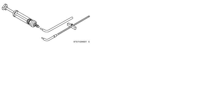
|
PERIODIC MAINTENANCE 2-13 |
||
|
Special Tools |
||
Steering Stem Nut Wrench: |
Fork Piston Rod Puller, M12 × 1.25: |
|
|
57001-1100 |
57001-1289 |
|
|
Jack: |
Fork Oil Level Gauge: |
|
|
57001-1238 |
57001-1290 |
|

2-14 PERIODIC MAINTENANCE
Periodic Maintenance Procedures
Fuel System
Fuel Hose and Connections Inspection
○The fuel hoses are designed to be used throughout the motorcycle’s life without any maintenance, however, if the motorcycle is not properly handled, the inside the fuel line can cause fuel to leak [A] or the hose to burst. Remove the fuel tank and check the fuel hose.
 Replace the fuel hose if any fraying, cracks [B] or bulges
[C] are noticed.
•Inspect that the hoses are securely connected and clamps are tightened correctly.
•When installing, route the hoses according to Cable, Wire, and Hose Routing section in the Appendix chapter.
•When installing the fuel hoses, avoid sharp bending, kinking, flattening or twisting, and route the fuel hoses with a minimum of bending so that the fuel flow will not be obstructed.
 Replace the hose if it has been sharply bent or kinked.
Throttle Cable Inspection
Throttle Grip Free Play Inspection
•Inspect throttle grip free play [B] by lightly turning the throttle grip [A] back and forth.
 If the free play is improper, adjust the throttle cable.
Throttle Grip Free Play
Standard: 2 3 mm (0.08 0.12 in.)
•Inspect that the throttle grip moves smoothly from full open to close, and the throttle closes quickly and completely in all steering positions by the return spring.
 If the throttle grip does not return properly, check the throttle cable routing, grip free play, and cable damage. Then lubricate the throttle cable.
•Run the engine at the idle speed, and turn the handlebar all the way to the right and left to ensure that the idle speed does not change.
 If the idle speed increase, check the throttle cable free play and the cable routing.
Throttle Grip Free Play Adjustment
•Loosencable. the locknut [A] at the upper end of the throttle
•Turn the adjuster [B] until the proper amount of throttle grip free play is obtained.
•Tighten the locknut.
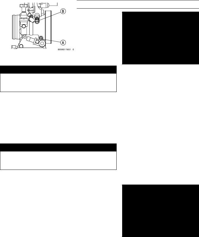
PERIODIC MAINTENANCE 2-15
Periodic Maintenance Procedures
 If the throttle grip free play cannot be adjusted with the adjuster at the upper end of the throttle cable, use the cable adjuster [A] at the carburetor.
•Free the fuel cut valve connector from the frame.
•Pull the boot off of the carburetor top. Make the necessary free play adjustment at the lower cable adjuster, tighten the locknut [B], and install the boot.
•Turn the handlebar from side to side while idling the engine. If idle speed varies, the throttle cable may be poorly routed or it may be damaged.

 WARNING
Operation with an improperly adjusted, incorrectly routed, or damaged cable could result in an unsafe riding condition.
Carburetor Inspection
Idle Speed Inspection
•Start the engine and warm it up thoroughly.
•With the engine idling, turn the handlebar to both sides.  If handlebar movement changes the idle speed, the throttle cable may be improperly adjusted or incorrectly routed, or it may be damaged. Be sure to correct any of these conditions before riding (see Cable, Wire, and Hose Routing in the Appendix chapter).

 WARNING
Operation with an improperly adjusted, incorrectly routed, or damaged cable could result in an unsafe riding condition.
•Check idle speed.  Adjust it as needed.
Idle Speed Adjustment
•First turn in the air screw [A] until it seats lightly, and back it out the specified number of turns. (see specifications in the Fuel System chapter)
•Start the engine and warm it up thoroughly.
•Turn the idle adjusting screw [B] to obtain desired idle speed. If no idle is preferred, turn out the screw until the engine stops.
•Open and close the throttle a few times to make sure that the idle speed is as desired. Readjust if necessary.
Air Cleaner Element Cleaning and Inspection
NOTE
○In dusty areas, the element should be cleaned more frequently than recommended interval.
○After riding through rain or on muddy roads, the element should be cleaned immediately.
○Since repeated cleaning opens the pores of the element, replace it with a new one in accordance with the Periodic Maintenance Chart. Also, if there is a break in the element material or any other damage to the element, replace the element with a new one.
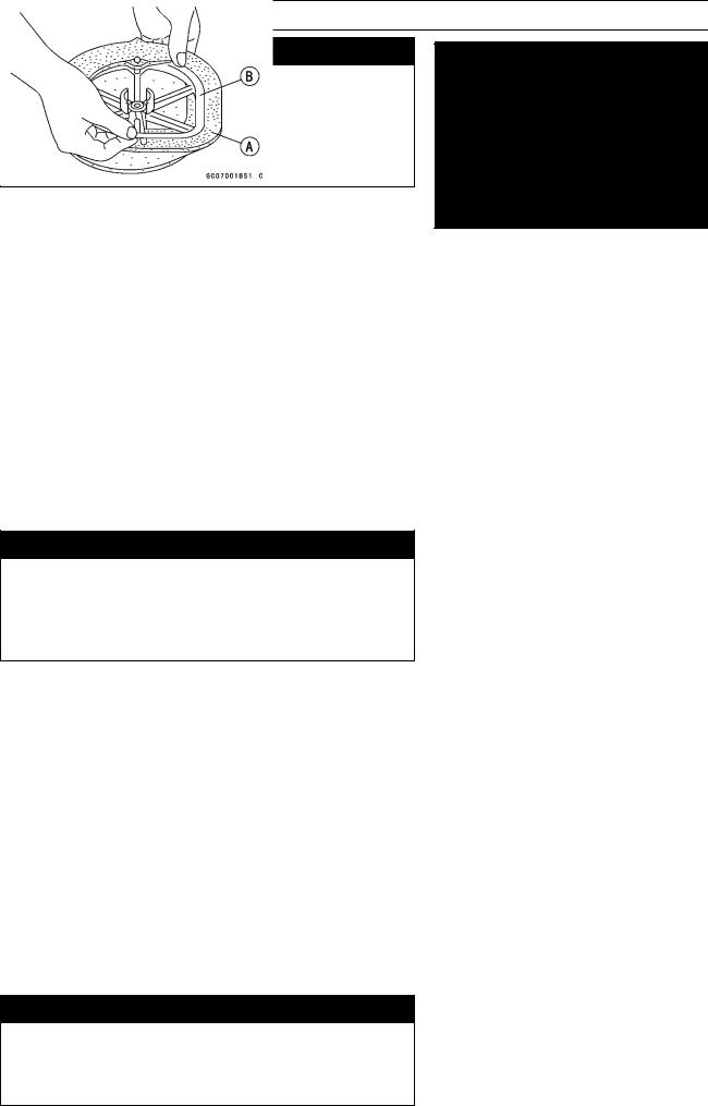
2-16 PERIODIC MAINTENANCE
Periodic Maintenance Procedures

 WARNING
Clean the element in a well-ventilated area, and take care that there are no sparks or flame anywhere near the working area; this includes any appliance with a pilot light. Because of the danger of highly flammable liquids, do not use gasoline or a low flash-point solvent to clean the element.
•Remove the air cleaner element, and separate the element [A] from the frame [B].
•Clean the element in a bath of a high-flash point solvent using a soft bristle brush. Squeeze it dry in a clean towel. Do not wring the element or blow it dry; the element can be damaged.
•Inspect all the parts of the element for visible damage.  If any of the parts of the element are damaged, replace them.
•After cleaning, saturate the element with a high-quality foam-air-filter oil, squeeze out the excess, then wrap it in a clean rag and squeeze it as dry as possible. Be careful not to tear the sponge filter.
•Assemble the element.
•Remove the towel from the carburetor.
•Install the element.
Fuel Tank and Tap Cleaning

 WARNING
Clean the fuel tank in a well-ventilated area, and take care that there is no sparks or flame anywhere near the working area. Because of the danger of highly flammable liquids, do not use gasoline or low flash-point solvent to clean the tank.
•Remove the fuel tank and drain it.
•Pour some high-flash point solvent into the fuel tank and shake the tank to remove dirt and fuel deposits.
•Pour the solvent out of the tank.
•Remove the fuel tap from the tank by taking out the bolts.
•Cleanvent. the fuel tap filter screen in a high-flash point sol-
•Pour high-flash point solvent through the tap in all lever positions.
•Dry the tank and tap with compressed air.
•Install the tap in the fuel tank.
•Install the fuel tank.
Cooling System
Check the coolant level each day before riding the motorcycle, and replenish coolant if the level is low. Change the coolant in accordance with the Periodic Maintenance Chart.

 WARNING
To avoid burns, do not remove the radiator cap or try to inspect the coolant level or change the coolant when the engine is still hot. Wait until it cools down.

PERIODIC MAINTENANCE 2-17
Periodic Maintenance Procedures
Coolant Inspection
Coolant Level Inspection
NOTE
○Inspect the level when the engine is cold (room or ambient temperature).
•Situateground.the motorcycle so that it is perpendicular to the
•Remove the radiator cap [A].
NOTE
○Remove the radiator cap in two steps. First turn the cap counterclockwise to the first stop and wait there for a few seconds. Then push down and turn it further in the same direction and remove the cap.
•Inspect the coolant level. The coolant level [A] should be at the bottom of the filler neck [B].
 If the coolant level is low, add coolant through the filler opening to the bottom of the filler neck. Install the cap.
Recommended coolant:
Permanent type of antifreeze (soft water and ethylene glycol plus corrosion and rust inhibitor chemicals for aluminum engines and radiators)
Water and coolant mixture ratio:
1:1 (water 50 %, Coolant 50 %) Total amount:
KX125: 0.97 L (1.02 US qt.) KX250: 1.20 L (1.27 US qt.)
Coolant Deterioration Inspection
•Visually inspect the coolant.
 If whitish cotton-like wafts are observed, aluminum parts in the cooling system are corroded. If the coolant is brown, iron or steel parts are rusting. In either case, flush the cooling system.
 If the coolant gives off an abnormal smell, check for a cooling system leak. It may be caused by exhaust gas leaking into the cooling system.
Coolant Draining
The coolant should be changed periodically to ensure long engine life.

 WARNING
To avoid burns, do not remove the radiator cap or try to change the coolant when the engine is still hot. Wait until it cools down.
Coolant on tires will make them slippery and can cause an accident and injury. Immediately wipe up or wash away any coolant that spills on the frame, engine or other painted parts. Since coolant is harmful to the human body, do not use for drinking.
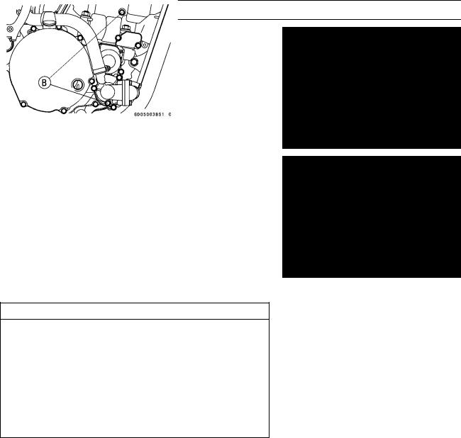
2-18 PERIODIC MAINTENANCE
Periodic Maintenance Procedures
•Remove the radiator cap.
NOTE
○Remove the radiator cap in two steps. First turn the cap counterclockwise to the first stop and wait there for a few seconds. Then push down and turn it further in the same direction and remove the cap.
•Place a container under the coolant drain plug (KX125)
[A]or plugs (KX250) [B], and drain the coolant from the radiator and engine by removing the drain plug on the water pump cover and the cylinder (KX250). Immediately wipe or wash out any coolant that spills on the frame, engine, or wheel.
•Inspect the old coolant for visual evidence of corrosion and abnormal smell (see Coolant Deterioration Inspection).
Coolant Filling
CAUTION
Use coolant containing corrosion inhibitors made specifically for aluminum engines and radiators in accordance with the instruction of the manufacture’s. Soft or distilled water must be used with the antifreeze (see below for antifreeze) in the cooling system. If hard water is used in the system, it causes scale accumulation in the water passages, and considerably reduces the efficiency of the cooling system.
Recommended Coolant
Type: Permanent type antifreeze (soft water and ethylene glycol plus corrosion and rust inhibitor chemicals for aluminum engines and radiators)
|
Color: |
Green |
|
Mixed ratio: |
Soft water 50%, Coolant 50% |
|
Freezing point: |
−35°C (−31°F) |
|
Total amount |
KX125: 0.97 L (1.02 US qt.) |
|
KX250: 1.20 L (1.27 US qt.) |
•Install the drain plug.
○Replace the gasket with a new one.
•Tighten:
Torque — Coolant Drain Plug on Water Pump Cover: 8.8 N·m (0.9 kgf·m, 78 in·lb)
Coolant Drain Plug on Cylinder (KX250): 8.8 N·m (0.9 kgf·m, 78 ft·lb)

PERIODIC MAINTENANCE 2-19
Periodic Maintenance Procedures
•Fill the radiator up to the bottom of the radiator filler neck [B] with coolant [A], and install the cap, turning it clockwise about 1/4 turn.
NOTE
○Pour in the coolant slowly so that it can expel the air from the engine and radiator. The radiator cap must be installed in two steps. First turn the cap clockwise to the first stop. Then push down on it and turn it the rest of the way.
•Check the cooling system for leaks.
Air Bleeding
Before putting the motorcycle into operation, any air trapped in the cooling system must be removed as follows.
•Start the engine, warm up the engine thoroughly, and then stop the engine. Wait until the engine cools down.
•Remove the radiator cap.
•Inspect the coolant level.
 If the coolant level is low, add coolant up to the bottom of the filler neck.
•Install the radiator cap.
•Inspect the cooling system for leaks.
Water Hoses and Connections Inspection
○The high pressure inside the water hose can cause coolant to leak [A] or the hose to burst if the line is not properly maintained. Visually inspect the hoses for signs of deterioration. Squeeze the hoses. A hose should not be hard and brittle, nor should it be soft or swollen.
 Replace the hose if any fraying, cracks [B] or bulges [C] are noticed.
•Check that the hoses are securely connected and clamps are tightened correctly.
Torque — Water Hose Clamp Screws: 1.5 N·m (0.15 kgf·m, 13 in·lb)
Engine Top End
Cylinder Head Warp Inspection
•Lay a straightedge [A] across the lower surface of the head at several different points, and measure warp by inserting a thickness gauge [B] between the straightedge
and the head.
 If warp exceeds the service limit, repair the mating surface. Replace the cylinder head if the mating surface is badly damaged.
Cylinder Head Warp |
|
|
Service Limit: |
0.03 mm (0.0012 in.) |
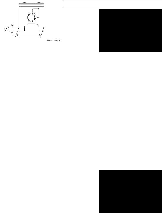
2-20 PERIODIC MAINTENANCE
Periodic Maintenance Procedures
Cylinder Wear Inspection
NOTE
○Measure the cylinder inside diameter when the cylinder is cold (room or ambient temperature).
•Visually Inspect the inside of the cylinder for scratches and abnormal wear.
 If the cylinder is damaged or badly worn, replace it with a new one.
•Since there is a difference in cylinder wear in different directions, take a side-to-side and a front-to back measurement shown in the figure.
 If any of the cylinder inside diameter measurements exceeds the service limit, the cylinder must be replaced with a new one since the PLATING cylinder cannot be bored or honed.
|
(A): |
KX125 — 15 mm (0.6 in.) |
|
|
KX250 — 30 mm (1.2 in.) |
||
Cylinder Inside Diameter |
||
|
KX125: |
||
|
Standard |
54.010 54.025 mm (2.1264 2.1270 |
|
|
in.), and less than 0.01 mm (0.0004 |
||
|
in.) difference between any two |
||
|
measurements. |
||
|
Service Limit |
54.10 mm (2.130 in.), or more than |
|
|
0.05 mm (0.020 in.) difference |
||
|
between any two measurements. |
||
|
KX250: |
||
|
Standard |
66.400 66.415 mm (2.6142 2.6148 |
|
|
in.), and less than 0.01 mm (0.0004 |
||
|
in.) difference between any two |
||
|
measurements. |
||
|
Service Limit |
66.46 mm (2.617 in.), or more than |
|
|
0.05 mm (0.020 in.) difference |
||
|
between any two measurements. |
Piston Diameter Measurement
•Measure the outside diameter of the piston 15.0 mm (0.59 in.) (KX125) or 20.5 mm (0.81 in.) (KX250) [A] up from the bottom of the piston at a right angle to the direction of the piston pin.
 If the measurement is under the service limit, replace the piston.
(A): KX125 — 15.0 mm (0.59 in.) KX250 — 20.5 mm (0.81 in.)
 Loading…
-
Страница 1
KX125 KX250 KX500 Motorcycle Service Manual[…]
-
Страница 2
[…]
-
Страница 3
This quick reference gu i de will Issist you in locating e desired topic or procedure . • Bend the pages back to match the black tab of th e desired chap t er nu mbe r wi th the black tab on the edge at each table of contents page . • Refer to the sectional table of contents for the exact pages to locate the specif i c top ic req u i red . Quic[…]
-
Страница 4
[…]
-
Страница 5
Kawasaki KX125 KX250 KX500 Motorcycle Service Manual[…]
-
Страница 6
A ABDC AC ATDC BBDC BDC BTDC ‘C DC F ‘ F It 9 h L LIST OF ABB REV I ATI O NS ampere(s) Ib Pound(s) after bottom dead center m meter(s) alternating current min minute(s) after top dead center N newton(s) before bottom dead center Pa PascaHs) bottom dead center before top dead center degree(s) Celsius direct current farad(s) degree(s) Fahre[…]
-
Страница 7
Foreword This manual is designed primarily for use by trained mechanics in a properly equipped shop. However , it contains enough detail and basic in formation to make it useful to the owner who desires to perform his own basic main- tenance and repair work. A basic knowledge of mechanics , the proper use of tools , and workshop procedures must be […]
-
Страница 8
NOTE o This note symbol indicates points of partic — ular interest for more eff i cient and con- venient operation . -Indicate a procedural step or work to be done . o lndicates a procedural sub — step or how to do the work of the procedural step it follows . It also precedes the text of a WARNING , CAUTION , or NOTE . * Indicates a conditional ste[…]
-
Страница 9
GENERAL INFORMATION , — , D General Information Table of Contents Before Servicing … . ……… _ , _ . . . ….. . .•. . … . … . • … …. _ ,_… … . . .. … . . . . .. .. . 1 — 2 Mode l I dentification …… . …… . ……………. .. . . ……………………… . …. ‘-4 General Specificat i ons ……. . .. . ….[…]
-
Страница 10
1·2 GENERAL INFORMATION Before Servicing Before starting to service a motorcycle. carefu l reading of the applicable section is recommended to eliminate unnecessary work . Photographs , diagrams , notes, cautions , wa rn ings, and detailed des- criptions have been included wherever necessary . Nevertheless , even a detailed account has limitations[…]
-
Страница 11
GENERAL INFORMATION 1 -3 (11) Oil Seal and Grease Seal Replace any oil or grease seals that were removed with new ones, as removal gene r ally damages seals. When pressing in a seal which has manufacturer’s marks, press it in with the marks facing out. Seals should be pressed into place us ing a surtable driver . which contacts evenly with the[…]
-
Страница 12
1 -4 GENERAL INFORMATION Model Identification KX 125 · F1 Left Side View KX125 — Fl Right Side VIew[…]
-
Страница 13
GENERAL INFORMATION 1 — 5 KX250 · F 1 left Side View KX250 — F 1 Right Side View[…]
-
Страница 14
1-6 GENERAL INFORMATION KX500 — Dl Left Side View KX500 — 01 Right Side View[…]
-
Страница 15
General Specification s Items Dimens i on s: Overall length Overall width Overall height Wheelbase Road clearance Seat height Dry weight Curb weight : Front Rear Fuel tank capacity Engine : Type Cooling system Bore and st roke Displacement Comp r ession ratio Maximum horsepower Maximum torque Carburetion system Starting system Ignition system Ignit[…]
-
Страница 16
1 · 8 GENERAL INFORMATION Item Frame : Type Steering angle Caster trake angle) Trail Fr ont tire: Make/Type Size Rear tire: Make/Type Size Front suspension: Type Wheel travel Rear suspension : Type Wheel travel Brake type: Front and Rear Effect ive d isc diameter: Front Rear KX125 · Fl Tubular, si ngle do wn tube 45° to Bither side 27′ 122 […]
-
Страница 17
Items Dim ens ion s : Overall length Overall w i dth Overall height Wheelbase Road clearance Seat height Dry weight Curb weight: Front Rear Fuel tank capacity Eng i ne : Type Cooling system Bore and s troke Displacement Compression rat i o Maximum horsepower Maximum torque Carburetion system Starting system Ig ni tion system Ignition ti m i ng Spar[…]
-
Страница 18
‘ — ‘0 GENERAL INFORMATION Item Frame : Type Steering angle Caster (rake angle) Trail Front tire : MakelType Size Rear tire : Make / Type Size Front suspension: Type Wheel travel Rear suspension: Type Wheel travel Brake type : Front and Rear Effective disc d iameter: Front Rear KX250-F’ Tubular, single down tube 45 0 to either side 2[…]
-
Страница 19
Item s Dimensions : Overall length Overall width Overall height Wheelbase Road clearance Seat hei g ht Dry weight Curb weight: Front Rear Fuel tank capacity Eng i ne : Type Coo ling system Bore and stroke D is placement Compression ratio Ma ximum horsepower Maximum torque Carbure t ion system S tart ing system Ign it ion system Ignition timing Spar[…]
-
Страница 20
1 — 12 GENERAL INFORMATION Item Frame : Type Stee r ing angle Caster (rake angle) Trail Front type : T ype Rear t ype : Size Type Size Front suspension : Type Wheel tra vel Rear suspension : Type Wheel travel Brake type : Front and Rear Effective disc diameter : Front KX500 — 01 Tubular. single down tube 45° to either s i de 28 · 129 rnm 8RIDGEST[…]
-
Страница 21
GENERAL INFORMATION 1-1 3 P e ri od ic M ai nt e na n ce Ch a rt FREQUENCY Each Every Every E very A, OPERATION race 3 races 5 ra c es 10 races required Clutch·-adjust • Clutch and friction plates-<:heck t • R Throttle cable-adjust • Spark plug — -clean, gap t • R Air cleaner element-clean • Air cleaner element — replace Damaged Carb […]
-
Страница 22
[…]
-
Страница 23
GENERAL INFORMATION 1 — 15 Torqu e Fa stene r N -m kg-m It — Ib Remarks Eng in e Right Side : External Sift Mechanism Return Sp ring Pin (KX 125 , 250) 22 2 , 2 1 6,0 L IKX500) 20 2 , 0 14 , 5 L Clutch Spring Bolt s 9 , 3 0 , 95 82 in -Ib Neutral Set Le ver Bolt 9 ,8 1 ,0 87 in-Ib Clutch Hub Nut IKX 125) 78 8 58 L IKX250, 500) 98 10 72 Primary Gear[…]
-
Страница 24
1 — 16 GENERAL INFORMATION Torque Fastener N — m kg-m It-Ib Remarks Brakes : Caliper Mounting Bolts(Front . Rear) 25 2 . 5 18 .0 Brake Hose Banjo Bolts 25 2.5 18 . 0 Front Master Cylinder Clamp Bolts 8 . 8 0.9 78 in — Ib Brake Lever Pivot Locknut 5 . 9 0 . 6 52 in — tb Brake Disc Mounting Screws (Front , Rear) 9 . 8 1 . 0 87 in — tb Caliper Bleed V[…]
-
Страница 25
GENERAL INFORMA T ION 1- 17 The table below , re l ating tig h ten in g torque to t hr ea d d i amete r , lists t h e basic torq ue f o r t h e bo l ts a n d n ut s . Use this tab l e for o n ly t h e bo l ts and nut s w hi c h do not r equire a speci fi c to r que va l ue . A ll of t he val u es are for use w i th dry solve nt ·cJeaned t hr eads […]
-
Страница 26
1- 18 GENERAL INFORMATION Cable Routing KX 125 : KX250 : 1 . Throttle Cable 2. Brake Hose 3 . Clutc h Cable 4 . Ignit io n Coil 5 . Stator lead 1. Throttle Cable 2. Clutch Cable 3, Brake Hose 4. Stator Lead 5. Radiator Breather H ose[…]
-
Страница 27
GENERAL INFORMATION 1 — 19 KX500: 1 . Ignition Coil 2 . Thrott le Cable 3 . Radiato r Beather Hose 4 . Stator Lead[…]
-
Страница 28
[…]
-
Страница 29
FUEL SYSTEM 2-1 Fuel System Table of Contents E x ploded V ie w …………….. … ….. , .. «. _._ …… . … . . … .. . . _ . _ . .. … .. … 2 — 2 Specifications ………………… . ……………….. _,_ . .. » … •. •……. ,….. 2 -4 Special Tools ………………………………………………. .. ….[…]
-
Страница 30
2 — 2 FUEL SYSTEM ……. ExPIOd ·· . ·· d · · · V ··:······ .. •· .. •··•··· lew ······ · ·· · ·· ·· · · ··· · · …. . … … . ….. . .. .. . .. .. . .. . .. . . . . …. . …. ……. ….. .. — , I I I I I I I I I I I I I I _____ J r- — I -I !Al’f~ i j : ~ I I’ ~ KX1 2 5 I ‘ .[…]
-
Страница 31
r- I I I I I I I I I I I I I I I I I I I I I I I I I I I I I ________ 1 __ _ l…. — KX 2 5 0 , 5 00 T 2 — —, I I I I I I I I I I I I I I FUEL SYSTEM 2 — 3 r I I j~ I I I I I I I I I I I I : ~ ifi! I ‘ L~~ : —— —T- — — — ~ — KX12 5 • — —-, I I I I I I I I I I I I I I I I I I I I I I _-.—J 87 i n- lb) n — 9 . 8 N -m ( 1. 0 :g , : ,[…]
-
Страница 32
2-4 FUEL SYSTEM Specifications KX125 ‘ Item Standard Service Limit Thronle Grip Free Play 2 — 3 mm — — — Carburetor Specifications : Make / type KEIHIN PWK35 — — — Main jet 148 — — — Throttle valve cutaway 6 — — — Jet needle R2071J — 3 — — — Jet needle clip position 3rd groove from the top — — — Slow jet 62 — — — Air screw 11 h (turns out) Ser[…]
-
Страница 33
FUEL SYSTEM 2-5 KX500 ‘ . Item Standard Service Limit Throttle Grip Free Play 2- 3mm — — Carburetor Specifications : Make / type KEIHIN PWK39 — — — Main jet 175 — — — Throttle valve cutaway 7 — — — Jet needle R1369N-3 — — — Jet needle clip position 3rd groove from the top — — — Slow jet 62 — — — Air Screw 1 112 (turns out) Service fuel le ve […]
-
Страница 34
2 · 6 FUEL SYSTEM ……… . .. . .. . ….. . …… . .. … . .. . .. ……………….. Special Tools ………… . .. … … . ……… . …. .. .. . .. . . …………… Along with common hand tools , the following more specialized tools are required for complete fuel system servicing . Fuel Level Gauge : 57001 · 122 Pressure Cable[…]
-
Страница 35
Throttle Grip and C a bl e If the throttle grip h as excessive free play due to cab l e s tr etch or m i sadjustment, t he r e will be a de l ay in throttle response . Also , the thrott l e va l ve may not open fu l ly at full throttle . O n the other han d , if the throttle g rip has no p l ay , t h e th r ottle wil l be h ard to co n tro l , a nd[…]
-
Страница 36
2 — 8 FUEL SYSTEM Throttle Cable In s tallat ion Notes — Install the throttle cable in accordan ce with the Cable Routing sect i on in the General Information c hapt e r. — After the i ns tallation , adjust the cable properly . I WARNING’ o()peration with an Inconectty routed or improperly adju s ted cable could result in an unsafe riding cond[…]
-
Страница 37
Carburetor ………………… . …………………………………. Since the ca r buretor re gulates and mixes the fuel and air going to the engine, there are two gene ra l types of carburetor trouble : too rich a mixture (too much fuel), and too lean a mix ture (too l ittle fuel) , Such troub l e can be caused by dirt. wear , maladjust- m[…]
-
Страница 38
2·10 FUEL SYSTEM Service Fuel level (below the bottom edge of the carbo body) KX125 : 1 . 0 ± , mm KX250: 1 .0 ± 1 mm KX500: 1 .0 ± , mm 1 . Fuel level Gauge: 5700 1 -122 2. Service Fuel level Service Fuel Level Adjustment I WARNING’ oGasoline Is extremely flammable and can be ex — plosive under certain conditions. Always stop the engine a[…]
-
Страница 39
Fue l System Clean I WARNING’ o Gasoline Is extremely flammable and can be explosive under certain conditions. Always stop the engine and do not smoke . Make sure the area Is well ventilated and free from any source of flame or sparks; this Includes any appliance with 8 pilot light. ePl ace a su i table containe r beneat h the carburetor . e T[…]
-
Страница 40
2 · 12 FUEL SYSTEM Carburetor Installation Notes -In stallation is the reverse o f removal . — Being careful not to bend or otherwise damage the jet need l e . Check to see that the t hr ottle valve goes all the way down i nto the carbureto r body , and slides smoothly . • When in sta lling the ca rbur eto r i nto the ca rburetor holde r. align […]
-
Страница 41
Carburetor Disassembly . Remove the carburetor. — Remove the throttle va l ve assembly and carburetor cap from the carbu retor cable lower end . · Oisassemble t he throttle valve assembly ; spring , retainer , connector.clip . jet needle . circlip and throttle valve . A. Spring O . Clip B . Retainer E . J et Needle C. Connector F . Throttle Valve […]
-
Страница 42
2- 14 FUEL SYSTEM Ca r bu r etor Assembly No t es — Assembly is the reverse of disassembly . — Clean the disassemb l ed parts before assembling . — Replace the f l oat bowl O-ring with a new one if it i s deteriorated or damaged. — Turn in the air screw fully but not t i ghtly , and then back it out 1 1f2 turns . A . Ai r Screw Carbure t or Clea n […]
-
Страница 43
— Remove the float valve needle . — Check the float valve need le for wear . * If the needle is worn as shown below , replace the valve needle . — Push the rod in the valve needle , then release it . * If the rod does not came out fully by spring tension , replace the va l ve n eedle . Float Valve We. Push and releue 1 . Rod 3 . Valve Needle Wear 2[…]
-
Страница 44
2 — 16 FUEL SYSTEM Ai, Cleaner Element Installation Notes -I nstallation is the reverse of removal. — W hen installing the element , coat the lip of the e l em en t with a t hi c k l ayer of all purpose grease to assu r e a co mp lete seal against the air c leaner e l e- ment base . Also , coat the base whe re the lip of the e lem e nt fits . A . C[…]
-
Страница 45
Fuel Tank Fuel Tank R emoval — Remo v e the seat. -T u rn the fue l tap to the OFF po s ition . -P ul l the f uel ho se o ff the fuel tap . I WARNING’ oG8501lne Is extremely flammable and can be ex- plosive under certain conditions. Always stop the engine and do not smoke. Make sure the area ls well ventilated and free from any source of flame[…]
-
Страница 46
2 — 18 FUEL SYSTEM Fuel Tap 1. D-ring 2 . Filter Sc r een ‘* If the fuel tap screen has any breaks or is deterio- rated . it may allow dirt to r each the carburetor, causing poor runni n g _ Replace the fue l tap . * I f the fuel tap l eaks. or allows fue l to f l ow w h en i t is at OFF position , replace the damaged D-ri ng. Fuel Tank Cap — […]
-
Страница 47
Reed Valve Reed Valve Remov al — Rem ove the ca rburet o r from the carbu r etor holder and air cleaner duct . -R emove the ca rburetor holder mounting bolts , and move the holder rearward . — Take the reed va l ve out of th e cy lind e r . -F or KX125 model ; remo ve the reed valve out of the c rankcase . RefJd Valve Installation — In s tallation […]
-
Страница 48
[…]
-
Страница 49
COOLING SYSTEM 3-1 Cooling System Table of Contents Exploded View ……….. . .. . ..• . … . …. . .•••… … ……. «……………….. . ….. 3·2 Specif i cations …….. .. . . .. . …. . • . .. . …… . .•. . …… . ,’ «, … . .. . . ••• •. …… …. . .. 3 — 5 Special Tool . .. ……. . .[…]
-
Страница 50
3 — 2 COOLING SYSTEM … . . . . . . . . Exploded ~i~~ «»»»»»»»»»»»»»»»»»»» KX125 :[…]
-
Страница 51
KX250 : TEM 3-3 COOLING SYS[…]
-
Страница 52
3-4 COOLING SYSTEM KX500: T1: T2: T3: 87 I.-Ibl 9 8 N-m 11,0 k g -m’ll a ft-Ibl . (I 5 kg-m , . I 1 5 N- m. 78 in-Ib (0 9 kg-m. 9 N-m .[…]
-
Страница 53
COOLING SYSTEM 3 -5 Spe ci fication s Item Standard Coolant : Type Pe r manent type of antifreeze for al uminum engines and radiators Color G r een Mixed ratio Soft wate r 50%, Coolant 50% Total amo u nt : KX125 O.SS l KX250 1 . 1 l KX 5 00 1.3 l Radiator : Cap r elief p r essu r e 95 — 125 k P a 10.95 — 1 . 25 kg / cm 2 , 1S psil ……… . .. . […]
-
Страница 54
3 — 6 COOLING SYSTEM Coolant Check the coo lant l evel each day before riding the motorcycle . and replenish coolant if the level is low . Change the coo lant in accordance with the Periodic Maintenance Cha rt (see the General Information chapte r ). I WARNING’ a To avoid burns , do not remove the radiator cap or try to Inspect the coolant lev[…]
-
Страница 55
e place a can t amer under the coolant drain p l ug. and d r ain the coolant from the r a diator a nd engine by re moving the drain plug at the bottom of the wate r pu m p cover. Immed iate ly w ipe o r was h out any coo lant t hat spills on the frame , engine , o r w heel. A. Wa t er Pump Cove r B . Drain Plug A . Wate r Pump Cover B . Drain Plu g[…]
-
Страница 56
3 — S COOLING SYSTEM ,:r If hard water I. used in the system, It causes scale accumulation In the water passages , and considerably reduces the efficiency of the cool — Ing system . The coolant provided when shipping Type Permanent type antlf’.8ze Color Mixed ratio Fr •• zlng point Total amount for aluminum engln •• and radiators Green[…]
-
Страница 57
— Remo ve the pre ssu re teste r, repleni s h the coolant, and install the radiator cap * If the pressure drops and no external sou r ce is found, check for internal leaks. Check the cylinder head gasket for leaks. Cooling Sys t em Flushing Over a period of t i me, the coo li ng system accu- mu l ates rust , sc ale , and lime in t he water jacket a[…]
-
Страница 58
3 — 10 COOLING SYSTEM KX500 : A . Wa t er Pump Cove r B. B olts Water P ump Cover Ins t alla t io n No t es ‘I nstallat i on is the reverse of removal. — Replace the pump cover gasket with a new one. — Fill the cooling system (see Coolan t Fi ll ing) . Impe ll er Removal e Orain the coo l ant (see Coolant D r ai n ing) , . Remove the cove r bo[…]
-
Страница 59
Water Pump Shaft In sta llation KX125 , 250 : 1 1 . Oil Seal 3. Marked Side 2. Wate r Pump Shaft 4 . Right En gine Cover KX500 , 1 2 3 1 . Oil Seal 3. Marked Side 2 . Wate r Pump Shaft 4 . Right Engine Cover o Be sure to apply a molybednum disulf i de grease to the water pump s haft when installing . If it is in — stalled dry . the seals may wear e[…]
-
Страница 60
3 — 12 COOLING SYST EM · Press the ball bearing into the hole with a bearing driver set (specia l too l: 57001-1 1 29) untif the bear — ing is bottomed against the step . Radiato r Radia t or Removal — Remove the radiator cover(s). — Drain the coolant ( see Coolant Draining) . — loosen the hose clamps , and pull off the cooling and breather hoses […]
-
Страница 61
a Keep t he air nozzl e over 0 . 5 m 120 in . 1 away from the radiator . a Blow air perpendicularly to the rad i ator core. a Navar blow air at an angle against the fins but straight through them in the direction of natural air flow . a N a var s hake the air nozzle at a right angle against the fins . be s ure to move it at a level with the fins . […]
-
Страница 62
3 — 14 COOLING SYSTEM Cooling Hoses, Breather Hose Installation Notes — In sta ll the coo ling noses or breather hose being careful to follow the preformed bends (see Exploded View , H ose Rout ing in the Cenerallnformation cha~ ter1 Avoid sharp bending. kinking,. flattening. o r twisting . — Tighten the hose clamps secu rel y . A . Cooling Hoses B[…]
-
Страница 63
ENGINE TOP END 4- 1 Engine Top End Table of Conten t s E x ploded View ………………………………….. _ ……… .. ………… . …… . Specifications …………………• _ . . . …. . .•••.. . .. .. …. . . … …. .•• ……………. Special Tools . .. . … . …….. . ……. . .. . … . …….. . …. . . […]
-
Страница 64
4-2 ENGINE TOP END Exploded View T1 : 25 N — m 12 . 5 kg -m . 18 .0 ft — Ib) T2 : 26N -m 12 . 6 kg — m . 19 .0 ft — Ibl T3 : 6 . 9 N — m (0 . 7 kg — m. 81 In — Ibl T4 : 9 . 8 N — m 11 . 0 kg -m . 87 In — fbI T5 : 25 N -m 12 . 5 kg — m . 18 . 0 ft — Ibl T6 : 8 .9 N -m 10 . 7 kg -m . 61 In — fbI T7 : 8 . 3 N -m (0 . 86 kg -m , 74 in — Ib) T2[…]
-
Страница 65
KX250 : 18 . 0 ft — Ibl 25 N-m 12 . 5 kg -m . 19 . 0 ft — Ibl T1 : 25 N-m (2 .6 kg -m . 61 I n — Ib) T2 : 6 9 N -m 10 . 7 kg — m , 87 in — Ib) T3 : 9 ‘ S N -m (1 . 0 k g — m ‘ 26 ft — Ibl T4 : 34 N -m 13 . 5 k9 : ~ : 11 fHb) T5 . 15 N — m 11 . 5 kg 87 in — Ibl T6 : 8 N-m ‘1 .0 kg -m . 87 in — Ib) T7 : 9 . m 11.0 kg -m . T8 : 9 .8 N ?[…]
-
Страница 66
4-4 ENGINE TOP END KX500 : n : T2: T3: T4 : T5 : T6: T7 : 26 N — m (2 6 k 25 N-m (2’S k g — m • 18 ft-Ib) 6.9 N-m (0 7 :-m . 19 ft — Ib ) 34 N-m (3 6 k g-m , 61 in — Ibl 20 N -m (2 ‘ O k g-m . 25 ft — Ib) 9 . 8 N -m 11 0 :-m. 14 . 5 fHb) 9 .8 N -m (1 ‘ 0 k g -m . 87 in — Ib) . g-m , 87 In — Ib)[…]
-
Страница 67
ENGINE TOP END 4-5 Specifications KX125: Item Standard Service Limit Cylinder Head: Cylinder compression ( usable range) — 770 — 1200 kPa (7.7 — 12 kg / cm 2 • 109-171 psil Cylinder head warp — 0 . 03 mm Cylinder. Piston: Cylinder inside diameter 56 . 015-56 . 030 mm 56 . 10 mm Piston diameter 55 . 940 — 55 . 955 mm 55.79 mm Piston / cylinder[…]
-
Страница 68
4-6 ENGINE TOP ENO KX250 : Item Cylinder Head : Cylinder comp ression Cylinder head warp Cylinder . Piston : Cylinder inside diameter: Piston diameter : Piston / cylinder clearance Piston ring / groove cl ea ranc e Pi ston ring groove width Piston ring thickness Piston ring end gap Piston Pin diameter P iston pin hole diameter Small End i n side di[…]
-
Страница 69
ENGINE TOP ENO 4-7 KX500 : Item Standard Service Limit Cylinder Head: Cylinder compression (usable range) — 735- 1150 kPa 17.35- 11.5 kg / em’, 105 — 1 64 psi! Cylinder head warp — 0 . 03 mm Cylinder. Piston: Cylinder inside diameter 86 . 020-86.035 mm 86.10 mm Piston diameter 85 . 910-85.925 mm 85.80 mm Piston / cylinder clearance 0.105-0[…]
-
Страница 70
4 — 8 ENGINE TOP END .. .. . .. . . . . . . .. .. .. . . . …. …. …………….. . …… . . .. .. . Special Tool Compres s ion Gauge : 57001 · 221 Adapter : 57001 · 1159 Piston Pin Puller Assembly : 57001 — 910 Pi s ton Ring Plie,s : 6700′ — 115 o o o[…]
-
Страница 71
.. . ……. ………………………… . … . . .. .. . ……….. Cylinder Head Cylinder Compression Measurement — Start the engi n e — T hor oughly wa rm up the engine so that the engine oil between the piston and cylinder wa ll wi ll he l p seal comp r ession as it does during normal running . — Stop the engine . — Remove the spark plug. […]
-
Страница 72
4-10 ENGINE TOP END — Tighten the cylinder head bolts o r nuts to t h e spe- cified to r que. Tighten i ng T o rqu e: 25 N-m (2 . 5 kg · m. 18 ft — Ibl — Tighten the spark plug to the specified torq u e . Ti gh t ening Torque : 27 N-m 12 _ 8 kg-m_ 20 ft — Ibl C yli nd er H ead Wa rp In sp e cti on • Lay a straightedge ac r oss t h e lower surfac[…]
-
Страница 73
ENGINE TOP ENO 4 — » KX500: — Remove the idle gear. — Lift up the right and left exhaust va l ves until the gear surfaces a re flush with cylinder surface . p A. Shaft Lever C. Retaining Sc rew . B. Shaft lever Mounting Nut 0 KX’25 : — Remove the main exhaust valve cover bolts, and remove the cover and gasket. A. Cover B . Gasket — Pull o[…]
-
Страница 74
4 — 12 ENGINE TOP END — Remove the cylinder. and remove the main exhaust va l ve . A. Main Exhaust Va l ve KX250 : — Up side dow n the cylinder . ‘ Remove the plug and gasket. A. Plug B . Gasket ‘ Push in the operati n g rod as far as it will go . This cause to align the punch ma r ks on the exhaust va l ve with the notch on the operating[…]
-
Страница 75
KX50 0 : — Up si de down the cy lind er . — Remove the plug and gasket. — Remove the pin on the cylinder . — Remove the va l ve guide from the exhaust va lve . A. Exhaust Valve C. Pin B. Valve Gui d e — Unbolt the left plug . — Pull up the exhaust valves , and then pull out the va l ve operating rod to t he right side . A . Valve Ope r ating Rod 8 […]
-
Страница 76
4-14 ENG.lNE TOP END KX1 2 5 Model E x hau s t V a lv e Op e ratin g R od In s tall a t io n 3 @) 00 I D~D I’ D ) 1 . Ex h a u s t Va l v e s 2. Idle Ge ar 3 . Pu n c h Ma rk 4 . Gu i d e 5 . M ai n Ex h a u s t V al ve[…]
-
Страница 77
aFo r KX2S0 model ; tighten the main exhau st valve b r acket mounting bolts secu rely . Check that there is no gap between the bracket and cyli nder. 00 1. No Cap 2. Bracket 3. Main Exhaust Va l ve ENGINE TOP END 4 — 15 o Engage the valve pinions with the rod rack so that the paint marks on the pinions are positioned to- ward the front af the engi[…]
-
Страница 78
4 — 16 ENGINE TOP END T ig htening Torque 20 N- m 12 . 0 kg-m. 14 .5 ft — Ibl A . Valve Opera t ing Rod D. Exhaust Va l ves B . Oil Seal E . Va l ve Guides C. O — Ring O Put the exhaust va l ves into the holes in the cyl- i nd er. o AppJya 2 -s troke eng i ne oi l to the teeth of the valve operating rod . o Pull up the exhaust va l ves , inse rt th[…]
-
Страница 79
Cylinde r Installation Notes — Installation is (he reverse of removaL — Scrape any carbon out of the exhaust port . — Check for a crust of minerals and rust in the cy linder water jacket, and r emove them if necessary . — Replace the cy lind er base gaske t with a new one . — Apply engine oil to the piston s urface , piston rings and cylinder bore […]
-
Страница 80
4-18 ENGINE TOP END — When installing the piston rings on the piston , note the following ; o lf installing the piston rin gs by hand . first fit one end of the piston ring against the pin in the ring groove , spread the ring opening with the other hand and then s lip the ring into the groove . aFar the KX250 model ; both the top and the seco nd ri[…]
-
Страница 81
KX125 : Standard : SelVice Umit: KX250 : Standanl : 56 . 015 — 56 . 030mm , and less than O . 01mm difference between any two measurements . 66 . 10mm. or more than O.05mm difference between any two measurements . 67 . 400 — 67 . 415mm . and leas than O . Olmm difference between any two measurements . Service Umit: 67 . 48mm . Of more than 0 . 06mm[…]
-
Страница 82
4-20 ENGINE TOP END Piston Ring . Piston R ing Groove Inspection • Visuallv inspect the piston rings and the piston ring grooves . * If the rings are worn uneven l y or damaged , they must be replaced . * If the piston ring grooves are worn unevenly or damaged , the piston must be rep l aced and fitted with new rings . • Check fOl’ uneven […]
-
Страница 83
Pi s ton Pin Diameter KX1 2 S, Standard : Service lim i t : KX2S0 , Standard : Servi c e L i m i t : KXSOO , Standard : Service Lim i t : 15 . 995 — 16 . 000 mm 15 . 96 mm 17 . 995 — 18 . 000 mm 18 . 96 mm 18 . 995 — 19 . 000 mm 18 . 96 mm Pi s ton Pin Hole Di amete r KX12S , Standard : Service L i m i t : KX2S0 , Standard : Service L i mit : KXSOO[…]
-
Страница 84
[…]
-
Страница 85
ENGINE RIGHT SIDE 5 — ‘ Engine Right Side Table of Contents E xpl oded View ………. . • . .. .. …….••………… ,….. . . .••• .. …….. . …. .. …… 5 -2 Specifications ……….. » ……….. , .. . .. . ……….. , ……….•………….. ,. ,… 5 — 5 Special Tool s .. … …. . …………. .. ..[…]
-
Страница 86
~ : 2 ENGINE RIGHT SIDE … «» . Exploded ~·i. · · · ·· · «· · ·· .. . …. . … … . .. . ………… . . .. … … . . . . . w . .. . KX . . . . 125 : . . . . . . . . . . . .. .. . .. … . ….. .. ………. o ~ ? «,,~(i)’~ o ®~i/~’ ~ . ~i ‘ »’-» .. T3 : 9 . 3 N’ m (0[…]
-
Страница 87
KX250 T1, 9 . 3 N·m 10 . 95 kg -m. 82 In·lbl T2: 9 .8 N -m 11 .0 kg -m , 87 In — Ib) T3: 98 N -m (10 kg -m , 60 ft — Ib) T4 : 9 . 8 N — m (1.0 kg -m . 87 in — Ibl T5 : 3 . 9 N — m (0 . 4 kg -m . 35 in — Ibl T6 : 2 .0 N-m (0 . 2 kg -m . 17 in — Ibl T7 : 9 . 8 N — m 11 . 0 kg -m . 87 in — Ibl T8 : 9 . 8 N — m (1 . 0 kg -m . 81 in — Ibl T9 : 22 N-m […]
-
Страница 88
5 · 4 ENGINE RIGHT SIDE KX500 : ~(8 ~ T1: 9 . 8 N-m 11 .0 kg — m . 87 In — Ibl T2 : 3 . 9 N-m 10.4 kg-m. 36 In — Ibl T3 : 2 . 0 N-m (0 .2 kg-m . 17 In-Ibl T4 : 9 . 8 N-m 11 .0 kg-m. 87 in — Ib) T5 : 9 . 3 N-m 10 . 96 kg -m , 82 In-Ibl T6 : 98 N-m (10 kg — m . 72 ft-Ibl T7 : 9.8 N-m 11 .0 kg-m . 87 In-Ib’ T8 : 20 N · m 12 .0 kg · m . 14.6 ft[…]
-
Страница 89
. ………. . ………….. . …. . …………… . . • •. • •..• ••• • Specifications Item Clutch : Clutch lever free play Clutch Spring free length KX125 KX250 KX500 Friction plate thickness KX125 KX250 . 500 Friction plate / clutch housing clear- ance Friction and steel plate warp . . … . . …. . . . . , ……….•. […]
-
Страница 90
5 · 6 ENGINE RIGHT SIDE Right Engine Cover Right Eng i ne Cover Remo va l — Drain the t ran smission oil (see Transmission Oi l Change in the Engine Bottom End{Transmission chapter) . — Drain the coo l ant (see Coolant Change in the Coot- ing System chapter) , e Remove the fo ll owing parts . Kick Pedal C lu tc h Cable lower End Brake P eda l Impe[…]
-
Страница 91
— For K X 12 5 model ; turn the cl utch release lever to- ward the r ear . — Install the right engine cove r using the kick s haft oil se al guide (sp eci al t oo l ) to protect the cove r oi l sea l. A . Kick Shaft Oi l Sea l Guide : 5700 1- 263 — Fit t h e s haft le ve r bo ss in the groove of the va lve ope r ating (a d col la r. and in s tall t[…]
-
Страница 92
5 · 8 ENGINE RIGHT SIDE KX500 : A. lever S haft C. Allen Bolts B . Exhaust Advance r Assemb l y — Remove the p lu g sc r ew and take out the pos iti on· i n g pin . — Pull the lever shaft out of the right e ng i n e cove r. ! 8 A. Plug Screw C. l eve r S haft B . Positioning Pin -P ull off the wate r pump shaft (see Water Pump S h aft Removal in […]
-
Страница 93
Exhaust Advancer Assembly Disassembly /Assem bly Notes — The exhaust advancer assembly consists of the fo ll owing parts . E x haust Advancer A ss embly A . Exhaust Advance r Assembly 1 . P ins 2 . Rod 3 . Guide 4 . O-ring 5. Steel Balls 6 . Ho l der 7. Needle Bearing B . Space r 9 . Collar 10 . Collar 11 . Spring 12 . Gear — Check the exhaust adva[…]
-
Страница 94
5 · ‘0 ENGINE RIGHT SIDE Clut c h Proper clut c h le ve r play between the clut c h lever and the clutch lever holder is 2-3 mm . Play in — c r ease with cab le st ret c h and friction plate wear , necessitating adjustment. When there i s too much lever play, first try adjusting the cab le at the clutch le ver . I W AR NI NG’ o To a vo i[…]
-
Страница 95
KX125 : — Remove the fta t washe r and cl u tch p u sher in the clutch hub . A. C lut c h Pusher B . flat Washer — Remove the mag n eto cove r. — Use the r oto r ho lder and a d apter » A U (s pe cia l tools) to prevent the clutch from rotating, loosen the clutch hub nut (see E l ectrical System chapte r). — Remove the clutch s prin gs and spr[…]
-
Страница 96
5 — 12 ENGINE RIGHT SIDE Clutch Installation Note s -I nstallation is th e reverse of r e mo v al. — Apply mo l ybdenum disulfide grease to the outside of the s l eeve . — Apply transmission oil to the in side of the cl u tch housing gear and kick starter driven gear . — In sta ll the friction plates a nd stee l plates , sta rtin g with a friction […]
-
Страница 97
Friction Plate Thicknes s Measurement 1 . Friction Plate F ric t ion an d St e el Pl a t e Warp In s p ection • P l ace each friction p l ate o r steel plate on a surface plate , and measure the gap between the surface plate and each f r iction plate or steel plate . The gap is the amount of friction or stee l plate warp . * If any plate is warpe[…]
-
Страница 98
5 — 14 ENGINE RIGHT SIDE External Shift Mechani s m External Shift Mechanism Removal — Remove the following parts . Shift Pedal Magneto Cover Right Engine Cover Clutch Housing . Pull out the shift shaft with the shift mechanism arm and arm sp ring . and remo ve the return spring . A . External Shift Mechanism B. Neutral Set Lever C. Spring — Remo v[…]
-
Страница 99
Prim a ry Gear Primary Gear Removal — Remove the righ t engine cove r (see Right Engine Cover Remo v al) . — Remove the clutc h (see C lutch Removal) . e For KX125 model; remo ve t h e primary gear nut, spring washer, woodruff key, primary gear, and D- r ing. A. Primary Gear Nut — Fo r KX250. 500 mode l ; remove the cirdip, and take off the primary[…]
-
Страница 100
5 — 16 ENGINE RIGHT SIDE A . Chamfe r ed Side eF o r KX250 , 500 ; replace the o ld ci rclip with a new one . Klckstarter Kickstarter Assembly Removal — Remove the following part s. Right Engine Co v er C lut c h Housing . Pull the end of the kick s pring out of the hole in the crank c ase . KX126 : A. Kick Spring B . Kickstarter Assembly KX260 : A[…]
-
Страница 101
KX500 : A . Kick Spring B. Kicks t arte r Assembly C. Ratchet Guide D . Bolts — Remove the ratchet guide and bolts . — Remove the kicksta r ter assembly _ Kickstarter A ssembly I nstall at io n No tes -In sta ll ation is the reve r se o f removal. — Apply a non-permanent locking agent to the threads of the ratchet guide bolu . Kickstarte r Assem bl[…]
-
Страница 102
, , , . — 1 ., — , . • • ,[…]
-
Страница 103
ENGIN E REMOVAL II NSTALLATION 6 -‘ Engine Removal/Installation Table of Content s Expl o ded View …. . ……… . ……………… . ………. . ….. ……… …. … . . 6 — 2 Eng i ne Removal / I nstallation ……… .. … … … . ….. .• ……….. . .. ……… 6-3 Engine Removal ………………… . …………. _._[…]
-
Страница 104
6 — 2 ENGINE REMOVAL/INSTALLA TION .. . .. .. …. ………… .. . .. . … . . …………. . … . ……. Exploded View … …. . . … . . …………… . . …. . . …. . . …… ….. .. … . . r——————, I T1 I KX125 Model I I I I I I I I I I I I I I I I L ________ —«» / / / T1 : 25 N -m (2 .6 kg-m. 19.0 ft-Ibl[…]
-
Страница 105
Engine Removal / Installation Engine Removal — Drain the transmission oil (see Tran smission Oi l Cha n ge in t he Engine Bottom End{Transmission chap- ter). — Drain the coolant (see Coolant Change in the Cool- ing System chapter) . — Remove the fo ll owing parts . Right and Left S ide Cove r s Radiator Cover Seat fuel Tank Expansion Chamber Spark […]
-
Страница 106
[…]
-
Страница 107
ENGINE BOTTOM END/TRANSMISSION 7 · ‘ Engine Bottom End/Transmission Table of Contents Exploded View …………………….. . ………….. . … . ….. .. . …………….. .. 7-2 Specificat i ons ……………. . … . .. … .. . .. . ……. . .. . . . ………………… …….. 7 — 5 Special Too ls … . . . ……. . …. .[…]
-
Страница 108
DITRANSMISSION 7 — 2 ENGINE … .. .. … . .. . …. . . . . .. . .. . .. .. . BOTTOM EN . . .. .. .. .. ……. . ………. d View .. . .. . … . . . . . . . . .. .. . .. … … . . Explode …. ….. . ……………. KX125 : y! ~,,~ ~ b ~ / anent locking av-nt . l : Apply. no=m diautflde gr …. . M . Apply moly 62 In — Ib) ~ T 1: 6 . 9 N &[…]
-
Страница 109
KX250 : l : Apply a non-permanent locking agent . f1 : 5 . 9 N -m (0.6 kg-m . 52In — lb) T 2: 9 . 8 N-m 11.0 kg-m. 87 In — Ib) T 3 : 9 . 8 N -m 11.0 kg-m . 87 i n — Ib} T4 : 20 N -m 12 . 0 kg-m , 14 .5 ft — Ib) T5 : 9 .8 N-m 11.0 kg -m. 87 In — Ib) T6 : 22 N -m (2 . 2 kg-m . 16 . 0 ft — Ib) ENGINE BOTTOM ENOITRANSMISSION 7 -3[…]
-
Страница 110
7 -4 ENGINE BOTTOM ENO/TRANSMISSION KX500 : l : Apply. non — J*menent locking egent . T 1 : 5 . 9 N ‘ m (0 . 6 kg — m , 62 In-lbl T 2 : 9 .8 N-m 11.0 kg — m , 87 In-lbl T3 : 20 N ‘ m {Z .O kg -m . 14 .6 ft·lbl T4 : 22 N ‘ m 12 . 2 kg -m. 18 .0 ft — Ibl •[…]
-
Страница 111
ENGINE BOTTOM ENOITRANSMISSION 7-5 Specifications Item Standard Service limit Transmission Oil : Grade SE class — — Viscosity SAE 10W 30 o r 10W 40 — Amount : KX 125 0 . 65 L — — KX250, 500 0.8 L — — Crankshaft . Connecting Rod : Connecting rod : Bend and twist not more than O.03mm l O.20mm / l00mm 100mrn Big end ra dial clearance : KX125 0 . […]
-
Страница 112
7 — 6 ENGINE BOTTOM ENOITRANSMISSION Special Tools .. . …. … ………….. . …….. .. ….. . ……………… . . Along with common hand tools and precision instruments . specia li zed tools are required for com- plete crankshaft/transmission servicing. Clrcllp P1l e r s: 57001-144 Crankshaft Jig: 57001 · 1174 • Bearing Drive, Set : 5[…]
-
Страница 113
Transmission Oil I n order for the transmission and clutch to function p r operly, always maintain the transmission oil at the proper level and change the oil periodica l ly. I WARNING’ o Motorcycle operation w it h insufficient, deter i- orated, or c ontaminated transm iss ion oil will cause accelerated wear and may result in trans- mission s[…]
-
Страница 114
7 -8 ENGINE BOTTOM ENDITRANSMISSION KX250, KX500 , A. Tran s mission Oil Drain Plug • Check the gasket at the drain plug for damage . * Repla ce the gas k et with a new o n e if it is damaged . • After the oi l has co mpletely drained out, i n stall the drain p lu g with the gasket, and tighten it to the specified to r que . TIghten i ng Torque[…]
-
Страница 115
KX600 , A. Crankcase Bolts -I nstall the crankcase splitting tool and adapter (s pe cia l tools) i nto the left side of the crankcase . Be certain to screw the tool in all the way . A. Crankcase Splitting Tool Set: 57001- 1 096 B . Adapter : 5700 1 -136 — Tighten the bolt o n the c r ankcase splitting tool to split the c rank case halves . — Once t[…]
-
Страница 116
7-10 ENGINE BOTTOM ENO/TRANSMISSION NOTE 0 00 nor remove the bearings unless it is necessary . Removal may damage them. o lnstall the bearings for the crankshaft in the right and left crankcase so that their sealed sides face toward the oil sea/ side. Olighten the output and drive shaft bearing re- taining bolts to the specified torque . TIghtening[…]
-
Страница 117
Crankshaft . Connecting Rod Crankshaft Removal — Split the crankcase (see Crankcase Splitting) . — Remove the transmission shafts (see Transmission Shaft Removal) . — Using a press remove the c rank s haft from the right crankcase . *If the bearings stay on the crankshaft when sp l itting the crankcase or removing the c rankshaft from the right cra[…]
-
Страница 118
7 — 12 ENGINE BOTTOM ENO/TRANSMISSION Cra n ks h aft A sse mbl y No t es Since the assembly of the cra nk shaft dema n ds ex — acting tolerances . the disassembly and reassembly of the crankshaft can on l y be done by a shop having the necessary too l s and equip m ent. — Reasse m b l e the c r a n ks h aft accordi n g to the sta n dard tolerances […]
-
Страница 119
Crankshaft Runout 7.5 mm Turn the crankshaf t slowly. Crankshaft Alignmen t 7.5 mm * If the run ou t at eithe r point exceeds the serv i ce limit, a l ign the flywheels 50 that the runout falls wi thin the service limit • In the case of horizontal misal i gnment, which is the mo st com m on, st rike t h e projecting rim of the f l y- wheel wit h […]
-
Страница 120
‘-‘4 ENGINE BOTTOM END/TRANSMISSION Transmission Transmission Shaft Remo val — Split the c r ankcase (see Crankcase Splitting) . -Pull off the shift rod. and disengage the shift fo rk guide pins from t h e shift drum grooves . — Remove t he s h ift drum . — Remove the shift forks from the transmission gears . — Take out the drive shaft an[…]
-
Страница 121
_The drive s haft gears ca n be identified b y size ; the s mallest diameter gear is 1st gear, a nd the l argest is 5th (KX250, 500) or 6th (KX125). Be sure that all pa r ts are put back in the co rre ct sequence, facing the proper di r ect i on, and that a ll c irciip s a nd the washer are properly in place . Drive Shaft Gears KX125 : 1 . 1 st gea[…]
-
Страница 122
7 — 16 ENGINE BOTTOM ENOITRANSMISSION KX500, 1. 2nd gear (29 T; dog re cesses face right ) 2 . 4th gear (2 1T ; fork groove goes to the rig ht side of the gea r teeth) 3. 3rd gear (26T ; dog recesses face left ) 4. 5th gear (19T; fork groove goes to the left side of the gear teeth ) 5. 1st gear (32T; dog recesses face left) — Check that each gear s[…]
-
Страница 123
® A . Drive Shaft 3rd Gear Shift Fork B . Output S haft 4th Gear Shift Fork C. Output Shaft 5th Gear Shift Fork Drive shaft ‘, d gea r fingers a re s horter than shift fork t ho se of the other two shift forks Outp u t shaft 4th gear guide pin goes to cen- s h ift fork te, Output shaft 5th gear guide pin goes to left shift fork si de of the f[…]
-
Страница 124
7 — 1B ENGINE BOTTOM ENDITRANSMISSION A. S h ift Fo rk F i nge r * If a gear shift fo rk groove is worn over t h e serv — ice limit , the gear must be rep l aced . Gear Shift Fork Gr oov e Width Standard : IKX1 25 1 4.06 — 4 . 16 mm IKX 2 50 . 5001 4 . 55 — 4 . 85 mm Servi c e Limit : IKX1261 4.25 mm (KX2 5 0 . 6 001 4.7 6 mm A. Gear Shift Fo rk Gr[…]
-
Страница 125
A . Dog Hole B . Dog Ball Bearing Wear • C h eck the ball bearing o n both sides of t he s hift dr um , drive shaft an d o u tput shaft . o Si nc e the ball bearings are m a d e to extreme ly close tolerances. t h e wea r must be judged by feel rather tha n measurement. C lean each bearing in a high flash-point solvent , dry it (do not sp in the […]
-
Страница 126
[…]
-
Страница 127
WHEELSfTlRES 8 — 1 Wheels/Tires Table of Contents Exploded View …. . . .. …………. . …… . _ …… . .. . ………….. . …………….. . Specifications Specia l Tool s …… . ………… …. …. . .. .. …….. . .• •• .. ……………. …. …• .. .. Wheels . .. ….. ….. … . .. . . . ….. … . .. .. … . ?[…]
-
Страница 128
8 — 2 WHEELSITIRES Exploded View T1 : 5′ N-rn (5.5 kg-rn, 40 fNb) T2 : 9.3 N-rn (0 . 96 kg»,» , 82 In-4bl T3 : 26 N-rn (2:.5 kgom, 18 ft-tb) T4: 98 N-rn (10 kg-rn, 72 ft~bl 1’5 : 1.5 N-rn 10 . 15 kg»,», 13 in-tb)[…]
-
Страница 129
WHEELS/TIRES 8 · 3 Specifications Item Standard Service Limit Whoels: Rim runout : Axial Under 0 .5 mm 2mm Rad i al Under 0 . 8 mm 2mm Axle runou t/ l00 rnm Under 0 . 10 mm O . 2mm 10 . 7 mm : AL ) Tires: IKX125 , 250) Front: Size 80 / 1oo · 2151M — Make, type DUNLDP K490 ® DUNLOP K990 — Rear : S i ze : KX125 loo / loo · 1859M — K X 250 1[…]
-
Страница 130
8-4 WHEELSITIRES Special Tools Bearing Driver Set: 67001 · 1129 Bead Breaker A .. ‘ y : 57001-‘072 Tire Iron : 67001 — 1073 Rim Protector: 57001·1063 ClrcUp Pliers : 67001·143 NOTE o The t i re i rons (P I N 5 7 001 · 10 73 ) are i nc luded in the bead breaker assembly (P I N 57001 · 1072J .[…]
-
Страница 131
Whe e ls F ro n t Wheel Removal _ P l ace a stand or block under the motorcycle so that the front wheel is raised off the ground. — Rem ove the axle clamp nuts , a nd remove the wheel with t he axle. _ Remove the axle n ut, a nd remove the wh eel. 0 00 I1bt lay the wheel on the ground wrth the disc facing down . Thi s can damage or warp the dis c. […]
-
Страница 132
8 · 6 WHEELSITIRES Rear Whee/Installation Notes — Installatio n is the reverse of removal . — Fit the brake holder stop against the swi ng arm stop . A . Brake Holder C. Swing Arm B . Stop (B r ake Holder) O. Stop (Swina Arm) — Fit the caps to the irooves on the co ll ar . A . Cap B . Groove C. Co llar -In stall the drive c hain . Install the mast[…]
-
Страница 133
I WARNING. otf any spoke breaks, it should be replaced immedi- ately. A missing spoke pklces an additional load on the other spokes, which wi! eventualy cause other spokes to break. Rim Inspection • Inspect the rim for small c rack s, dents. bending, or warping . * If there is any damage to the rim, it must be re- placed . • Set a dial gauge ag[…]
-
Страница 134
8·8 WHEELSITIRES Tires Tire Removal 0 00 not lav the wheelan the ground with the disc facing down , This can damage or warp the disc. Place blocks under the wheel so the disc does not touch the ground . — Remove the whee l from the moto r cycle (see W h ee l s) . — To maintain wheel ba l ance, mark the va l ve stem pos it ion on the tire wit h c h[…]
-
Страница 135
— Position the tire on the rim so that the valve is at the ti re balance mark (the chal k mark made during removal or the yellow paint mark on a new tire) . A . Balance Mark — Tighten the bead protector nut securely , — C heck and adjust t he ai r pressure after in sta llin g . Tire Pressure Inspection / Adjustment — Us ing tire press ure gauge, me[…]
-
Страница 136
8-10 WHEELSITIRES Hub Bearing 000 not lily the wheelan the ground with the disc facing down . This can damage or wrap the disc. Place blocks under the wheel so the disc does n01 touch the ground . Hub Bearing Removal Notes -R emove the hub bearing by tapping evenly around the bearing inner race as shown . Bearing Removal 1 . Bar 2. Distance Co ll a[…]
-
Страница 137
Hub Bearing Inspection and Lubrication Since the wheel bearings are made to extremely dose tolerances, the clearance cannot normally be measured_ • For front hub bearing, turn each bearing back and forth while checking for roughness or bind ing . * If roughness or binding is found, rep l ace the bearing. • For rear hub bearing , wash the beari […]
-
Страница 138
[…]
-
Страница 139
FINAL DRIVE 9 — 1 Final Drive Table of Contents E x ploded V i ew ………………………………….. . ……………… . ….. . ….. . Spec i fication s Special Tools Drive Chain .. .. …. ….. ….. . ………………….. .. . _ ._ ……. . .. ……. . … …. . . . . . Drive Chain Slack Inspection …………. . ………. . […]
-
Страница 140
9 · 2 FINAL DRIVE Exploded View /1 __ — — ~ KX250 . 500 _— ~’ — I — — ~. — I . _ I Ii) I,) — I ,…… ….. (» I I I I ……… ….- I L.-……. …. …… …. I _- I ____ KX125 — I — — I ..J I _- 1 — — T1 : 29 N- m (3 .0 kg -m . 22 , 0 ft — Ibl T2 : 98 N- m (10 kg -m . 72 ft — Ibl[…]
-
Страница 141
FINAL DRIVE 9 — 3 Specifications Item Standard Service Limit Drive Chain: Make Daido — — Type 0 . 1.0 520 OS — 5 — Length : KX125 112link — KX250 , KX500 114 link — — Chain slack 50-60 mm less than 50mm, or more than 65mm 20 — link length 317 . 5 mm 323 mm Sprockets : Engine sprocket diameter KX125 50 . 98 — 51 . 18mm / 12T 50 . 7 mm KX250 , […]
-
Страница 142
9 — 4 FINAL DRIVE … ….. ………………. … … . . … . . . . .. . .. .. . .. …. …. . .. Drive Chain Drive Chain Slack Inspection — Support the motorcycle on its side stand . — Check the wheel alignment (see Whee l Alignment Jnspection l and adjust it if neces s ary ( see Wheel Alignment Adjustment) . NOTE o Clean the drive chain if i[…]
-
Страница 143
Wheel Alignment Inspection — Check that the notch on the l eft cha in adjuster aligns with the same swing arm mark as the right chain adjuster. A. Marks B . Notches NOTE o Wheel alignment can also be checked using the st raightedge or string method. I WARNING’ o Misaignment of the wheel wiN resutt in abnormal wear , and may resuft in an unsafe[…]
-
Страница 144
9 -6 FINAL DRIVE Dr ive Ch a in Make Daido Type 0.1. 0 52005-5 links: KX125 112 KX250 114 KX500 114 Drive Chain LubriC8tion — If the cnain appears especially dirty , it should be cleaned before lubrication with high flash-point sol- vent — Apply oil to the si des of the rollers so that oil wi l l penetrate to the rollers and bushings . — Wipe off a[…]
-
Страница 145
Sprocket Engine Sprocket Removal — Remove the following parts . Engine Sp ro cket Cover Drive C hain(free of e n gine s procket ) — Remove the c irclip , and pull off the engine sprocket . Engine Sprocket Installation Notes -In sta ll ation is the reverse of removal. A . Engine Sp r ocket B. Circlip — For KX 1 25 ; instal l the sprocket so that the[…]
-
Страница 146
9 -8 FINAL DRIVE Sprocket Oiamete, (Engine) 10(125 Standard : Service lImtt : 10(250. 500 Standard: Service limit: IR •• r) Standard : Service limit : 50.98-61.18 mm 50 . 7 mm 60.99 — 61 . 19 mm 60.7 mm 227.43-227.93 mm 227.1 mm NOTE o lf IJ sprocket requires replacement , the chain is probably worn also. When rep/acing 8 sprocket , inspect the[…]
-
Страница 147
BRA KES 1 0 · 1 Brakes T a ble of Con t ent s Exp loded V ie w ………………………… , …………… . ………………. . … . 10 -2 Spec i f ica ti ons . ……• •• ………………………………… . ……••.. , …… . ••.. 10 -4 Special T oo l …. . ……………… . . …………………………… […]
-
Страница 148
‘ ~~~I~~~’~’ ~ : I~~ . .. …… . … .. . . .. . . . .. . …………. . . ………… . . . 10 — 2 BRAKES …….. . ……. . . .. . ………. . ….. . . Front Di sc Brake @[…]
-
Страница 149
D isc Brake Rear j—@ » . ~ ~ I [!l . W fIJfIJ l..Jr I ‘I 52 in — Ib ) 9 N -m (0 .6 k g -m . 18 . 0 ft — Ib ) T1 : ~ 5 N -m 12 . 5 kg — rn. 78 In — Ibl T2 : 8 N -m 10 .9 kg -m . 18 .0 ft — Ib) T3 : ~ 5 N-m 12 . 5 kg -m . 69 in — Ibl T4 : 78 N-m (0 .8 kg — m . 87 in — Ibl T5 : ‘ s N-m 11 .0 kg -m . 78 in — Ibl T6 : 9 . (0 . 9 kg -m .[…]
-
Страница 150
10·4 BRAKES …… …………. .. …. . . …… . .. . ……….. .. . .. . . .. .. . . Specifications D isc Brake Item Standard Service limit Brake Adjustment : Brake lever p l ay Adjustable (to suit rider) — Brake pedal position Adjustable (to su i t rider) — Brake pedal play Adjustable (to su i t rider) — Brake Pads : Pad lining thic[…]
-
Страница 151
Disc Brakes [ WARNING’ o When working with the disc brake. observe the precautions listed betow . 1 . Never reuse old brake fluid . 2. Do not use flu id from a conta in e r that ha s been left unsealed o r that has been ope n for a long time . 3, Do n ot mix two types and brands of fluid for use i n the brake . This lowe r s the brake fluid bo[…]
-
Страница 152
10 · 6 BRAKES R ea r B rake Ped a l Pl ay Ad j u s tment — Adjust t h e rear brake peda l p l ay to suit you . — Loosen the adjuster locknu t and turn t he ad ju ste r o n t he rear master cy l inder . — After adj u stme n t, t i gh te n t he l ock nut sec ur e l y . A . Ad j uste r C. Br a k e Pe d a l B . Rea r Master Cy lin der D. l ock n ut Ca[…]
-
Страница 153
A . App l y compressed air . B . Cloth NOT E o lf t h e caliper is to be disassembled after removal and compressed air is not available, remove the piston using the following three steps before disconnecting the brake hose from the caliper. o Prepare a suitable dished container for brake fluid, and perform the work above it. oRemove the pads, sprin[…]
-
Страница 154
10 · B BRAKES Brak e Ped s: P ad Removal — Remove the caliper from the disc . and take out the piston side pad from the caliper holder . • Push the caliper holder toward the piston , and then remove the pad from the ca liper holder shaft. A. Pads C. Holder Shafts B . Caliper Ho l der P ad I ns ta llatio n • Push the ca l iper piston in by hand[…]
-
Страница 155
A. Banjo Bolt C. Rese r voi r B. Master Cylinder — When removing the brake hose , temporarily secu r e the end of the brake hose to some high p l ace to keep fluid loss to a minimum . — Unscrew the damp bolts, and take off the master cy linder as an assembly with the reservo i r and b r ake leve r . A. Clamp Bo l ts Front M aster Cylinder Insta/Jat[…]
-
Страница 156
10 — 10 BRAKES — When removing the brake hose , tempora r ily secure the end of the brake hose to some high place to keep fluid loss to a minimum . — Unscrew the master cylinder mounting bolts , and remove the master cylinde r with the reservoir . • Unscrew t h e reservoi r cap (the diaphragm comes off with the reservoir cap ) and pour the brake […]
-
Страница 157
Master Cylinder A ss embly Notes — Assembly is the r everse of disasse mbl y . — Take care not to damage the i nn e r s urf ace of the cy lind er , or the pi sto n . — Clean all parts with brake fluid o r alcohol , and apply brake fluid to the inner surface of the cylinder before assembly . — Tighten the brake lever pivot bo lt l ocknut sec urely .[…]
-
Страница 158
‘0 — ‘2 BRAKES Brake Disc : Disc I ns p ection • Visually inspect the disc. * If it is scratched or damaged , repla ce the disc . • l1easure the thickness of each disc at the lX>int where it has worn the most * Rep l ace t he disc if it has worn past the serv i ce l imit . 1 . Disc 2 . Measuring Area DIoc l1-kI<nou Standard : F[…]
-
Страница 159
Brake Fluid Level Inspect i on In spect the brake fluid level in the f ron t and r ea r brak e fluid re se rvoir s per io d ica lly . — Check the brake fluid level in the reservoir . NOTE o Hold the reservoir horizontal when checking brake fluid level. * The front and rear res ervo irs must be kept more than half fu ll with brak e flu id . If the a[…]
-
Страница 160
10-14 BRAKES Filling up the Brake line , . Open the bleed valve . 2. App ly the brake and hold it . 3. Close the bleed valve with the brake held app lied . 4. Then quickly release the brake . Bleeding the BrBke Line The brake fluid has a very low compression coeffj.. cient so that almost all movement of the brake lever or pedal is transmitted direc[…]
-
Страница 161
Brake Hose : Brake Hose RemovaVlnstallation Notes — When r emovi ng the brake hose , take care not to spill the brake fluid on the frame or other painted parts . — When removing the brake hose , temporarily secure the end of the brake hose to some high place to keep fluid los s to a minimum . o Brake fluid quk:Idy ruins painted or p&ated surfac[…]
-
Страница 162
[…]
-
Страница 163
SUSPENSION ,, — , Suspension Table of Contents Exploded View ………… . _ ………………………………………. . …… . .. … 11-2 Specifi ca tions …………..• _ ………. .. ………….. ….. . •• • • . ………•……….. 11-3 Special Tools …………………….•……………. , ….. . ………….[…]
-
Страница 164
11 — 2 SUSPENSION . .. . …••••••••• • •. . . .. . . . . . . .••••••••••….. .. . . . …. . .•.. . . Ex~loded View …. .. . . . . …….. .. .. . . … . . . . ………………… . . . . … . . • T1: 20 N · m 12 . 0 kg · m. 14 . 5 ft — Ibl T2 : 54 N -m 15 . 5 kg-m . 40 h-Ibl T3: 78 N -m (8 . […]
-
Страница 165
SUSPENSION 11 -3 Specifications Item Standard Service limit Front Fork : Air pressure Atmospheric pressure (Maximum air pres sure) 40kPa (0 .4 kg / cm 2 , Spsi) Oil viscosity: SAE 5W — Oil capacity : KX 125 535 ± 4mL — — 10(250 535 ± 4 mL — 10(500 597 ± 4 mL — (adjustable range) Oil le v el : K X 125 130 ± 2mm 100 — 160 mm ( full . Y com[…]
-
Страница 166
11 -4 SUSPENSION Spec i al Tools Front Fork Cylinder Holder : 5700′ — ‘245 Front Fork Oil Seal Driver ; 57001 — 1219 Front Fork Outer Tube Weight : 5700, — ‘218[…]
-
Страница 167
Front Fork Front Fork Adjustment The front fork shou ld always be adjusted for the rider’s weight and track co nditions by using one or more of the fo ll owing methods . Basically , there are five adjustment yo u can make to the front fork . oAi r pressure adjustment -Air pre ssu r e acts as a progressive spri ng and affects the entire range o[…]
-
Страница 168
11-6 SUSPENSION Softer E o 2 i Standard ..,. Harder 4 6 8 10 1 2 14 16 Number of turns clockwise u sab l e r8nge · 16 clicks Seated position adjuster turned fully counterc lockwi se o The left and right fork lega must have the same shock damping . -P ut the caps into the bottom of the outer tubes . Oil Level Adjustment — Use a jack under the engin[…]
-
Страница 169
Fork Spring Different fork springs are available to achieve ~itable front fork action in accordance wit h t h e rider’s weig h t and track co ndition. e Harder s prings make the fork stiffer, and rebound action quicker. e Softer sp rings make the fork softer, and rebound aciton slower. Fork Clamp Position Steering qualities are greatly affecte[…]
-
Страница 170
» · 8 SUSPENSION A. Top Bolt B . O·Ring C. Sp r ing Se at D . Spacer E. S pring F. Push Rod C . Up pe r H ole H. Si d e Hole — Pour in the type and amount of fo rk oi l s pecif ied . Recommended oil KAYABA 01 or SAE 5W Front Fork Oil Capacity : KX125 : KX250 ; KX500 ; 535 ::t; 4 ml 635 :t: 4 mL 597 ::l:: 4 mL • Pump the fork slowly seve ra[…]
-
Страница 171
— Mount the axle clamp s, and tighten the clamp nuts , first tighten the upper clamp nuts and t h en the lower clamp nuts to the specified torque . The arrow mark on the axle clamp must point upwards . A. Arrow Mark B . Upper Clamp Nuts C. lower Clamp Nuts Tightening Torque 9 . 3 N-m (0 . 95 kg -m , 82 in-ib) -Tighten the c aliper mounting bolts to[…]
-
Страница 172
11 · 10 SUSPENSION ecJC i n the bottom of the outer tube . — Remove the caps on the bottom of the outer tubes . eH old the front fork with a vise. — Stop the cy linder from turning by u si ng the cylinder holder (specia l tool) . Unscrew the cyli nder va lve assembly , and take the cy lind e r va l ve a sse mbly and aasket out of the bottom of the[…]
-
Страница 173
A . Inner Tube D . Washer B . Outer Tube Seal E. Outer Tube Guide Bu sh C. Oil Seal F . Inn er Tube Guide Bush — Remove the cy lin der base from the bottom of the outer tube . A . Outer Tube B . Cylinde r Base Front Fork Assembly Notes — Assembly is the reverse of disassembly . — Check the O-ring at t h e top bolt. Replace it with a new one if dama[…]
-
Страница 174
11·12 SUSPENSION — After in s talling the wa s her , install the oi l se al b y u s ing the fork oi l s eal driver (s pe c ial tool : 57(X)1· 1219, — Using the fork oil sea l dri ve r (s pecial tool : 57 001 · 1219) , in sta ll the du st sea l. .P our in the type and amount of fork oil s pecified , and adju st the oil lev e l (see Fork Oil C han[…]
-
Страница 175
Fork Spring Free Length Standard : KX125 , 250 : 548 mm KX500 , 553 mm Service Limit : KX125 , 250 : 537 mm KX500 : 542 mm . .. » …,.~-~ SUSPENSION 11 — 13 Rear Suspension IUni-Trak) Rear Shock Absorber : The rear suspension system of this motorcycle is Uni-trak . It consists of a rear shock absorber. swing arm , tie rod and r oc k e r ar m […]
-
Страница 176
11 — 14 SUSPENSION A . Rebound Damp i ng A dju ste r B . Mark Gas Reservoir Compression Damp ing Adjustment To adjust compression damping. turn the co mpre s- sio n damping adjuster on the gas r eservoi r with the blad e of a sc rewdri ve r until you feel a click . If the damper setting fee l s too soft or too sti ff , adjust i t in a cco rdance wi[…]
-
Страница 177
I WARNING’ O US8 onlv nitrogen ga s. 0 00 not incinerate the gas re se rvoir . Spring Prelo ad Adju stment — Remove the seat, right and left s id e covers . -l oosen the air clea ne r duct clamp screw. — Remove the silencer . — Remove the r ear frame a nd air cleaner case . A . Rear Frame B . Ai r Cleane r Case. • Pla ce a study block o r su[…]
-
Страница 178
11 — 16 SUSPENSION A. Rear S h ock Abso rb er B . Rea r S h ock Absorber Uppe r Mounting Bo lt o When pulling out the mounting bolts , lift the resr wheel slightly. Forcing or tapping on a bolt could damage the bolt. sleeve. and bearing . Rear Shock Absorber Installation Notes — Instal l ation is the reverse of remo va l. — Tighten the rea r shock […]
-
Страница 179
Rear Shock Absorber Disassembly ( Oil Change) The oil s hould be changed in the rear shock ab- sorbe r at least once per racing season . The f requenc y for best performan c e must be based upon riding conditions and rider ability . — Remove the rear shock absorbe r from the frame (see Rear Shock Absorbe r Removal) . — Remove the shock abso r ber s[…]
-
Страница 180
11 -1 8 SUSPENSION — Adjust t h e ga5 reservoir damp in g adjuste r to the softest position . -H o ld the upper end of the rear shock wit h the vise again . • Pry o r tap at the gap s in the stop with suitable tools to free t h e sto p from the rear s ho ck body. A ® A . Caps B . Tap — Slide the stop up to the top of the pu sh rod then lightly t[…]
-
Страница 181
— Check the circlip for weake nin g, deformity and flaws . If necessary , replace i t w ith a new one . I WARNING’ o lf weakened . deformed or flawed clrclip is used , the gas reservoir cap may not hold when Injecting the nitrogen gas. This would allow oil and internal parts to explode out of the reservoir. — Mount the circli p in the g ro ove[…]
-
Страница 182
, , — 20 SUSPENSION [ CAUTlO~] o lf the circlip i s not 8 certain fit In the groove in the rear s hock body . the push rod …. mbly may come out of the shock absorber when in;actlng the nitrogen gas or riding the motorcycle . A. Circlip — Pull up the push rod assembly against the c!rcl1p, & Force the stop into the rear shock body by lightly ta[…]
-
Страница 183
— Separate the ch ain guides and chain s lip pe r s from the sw in g a rm . Swing Arm Installation Notes -I nsta ll ation is the reverse of removal. — Apply plenty of molybdenum disulfide grease to the inside o f the needle bearings and s l eeves . — Tighten the sw i ng a rm pivot shaft nut , and the tie- r od rear mounting nut to the specified tor[…]
-
Страница 184
, , — 22 SUSPENSION Rocker Arm In sta llat ion Nores . ‘nstallation is the reverse of removal . — Apply plenty of mo l ybdenum disulfide grease to the inside of the rocker arm ho l e. outside of the s l eeve. and sp herical bearings . -T ighten the following parts to the specified torque . nghtenlng Torque : Rocker Arm Nut: 81 N · m 18.3 kg-m[…]
-
Страница 185
A . S l eeves Sleeve Outside Diameter Stand a rd : Service limit : Rocker Arm: Mounting B ol t Bend 21 . 987 — 22.000 mm 21.85 mm A bent bolt causes vib r ation. poor handling, and in s tabil ity . T o measure bo lt run out. remove the bolt , place i t in V blocks . and se t a dia l gauge to the bolt at a point half way between the blocks . Turn th[…]
-
Страница 186
[…]
-
Страница 187
STEERING 12 -1 Steering Table of Contents Exploded V iew ………… . …… . ….. , ‘ , . ……. . » …… ,’ . • . ••• …….. . . • • •• …… , 2 — 2 Special T o ol s …. . … . ……………… . . . ……..• •. ….. . .. .•••. • ………. •.•. .. . … 12 — 3 Steering Adju s tment […]
-
Страница 188
12 — 2 STEERING Exploded View _1 , , KX250 . 500 ….. .., … I —: ! iP~ KX250 , 500 , ——— ——-7 I fl / / I / / I / / / .. / I I / I / I ‘- ______ ____ _ _ …1 @ ,. Q Tl : 25 N · m {2.5 kg — m . 18 ft — Ibl T2: 44 N· m f4.6 kg — m, 33 ft · lbl T3 : 3 .9 N · m (0 . 4 kg — m . 36 In — Ib) T4 : 20 N· m (2 .0 kg -m . 14 . 6 ft — I[…]
-
Страница 189
Special Tools Stem Nut Wrench: 5700′ — 1100 Bearing Driver Set: 5700′ — «29 Stem Bearing Driver : 57001-137 Stem Bearing Driver Adapter: 57001 · 1074 STEERING 12 — 3 Stem Bearing Remover : 51001-‘ 107 Driver Press Shaft : 6700’ — ‘075 Driver : 67001-1106 57001-1076[…]
-
Страница 190
12 -4 STEERING Steering Adjustment Steering Inspection . Place a stand or b l ock under the m otorcycle so that the front wheel is raised off the ground . — With the front wheel pointing st raight ahead, alte r — nately nudge each end of the handlebar. The front wheel should swi ng fully left and right from the force of gravity until the fork hits […]
-
Страница 191
Steering Removal / In sta llat i on …… . ………………………………….. . ………….. Steering Stem Remova/ — Remove the fo ll owing parts. F r ont Whee l Brake Hose Clamp Caliper Mounting Bo l ts Master Cylinder Clamp Front Fender Handlebar Front Fork — Remove the s teering stem head nut and washer . — Remove the steering stem he[…]
-
Страница 192
1 2- 6 STEERING — Remove the tower inner race (with its grease seat) which is pressed onto the steering stem . A . Roller Bearing Steering S t em Race I nstallation N otes ‘ Installation is the reverse of removal. ‘ App ly grease to the outer races, and then drive them into the head pipe using the drivers and the driver press shaft (speci[…]
-
Страница 193
. . .. . …………… . _ ……. . _ …………… … . ……. _ .. . Steering Maintenance …. . .. . . .. …. . …………………. …. …. . . . ………… Steering Stem Bearing Lubrication • Remove the stee ring stem (see Stee rin g Stem Re- moval ). • Us i ng a high f l ash-point so l ve nt , wash the uppe r a n d lower tap[…]
-
Страница 194
[…]
-
Страница 195
ELECTRICAL SYSTEM 13-1 Electrical System Table of Contents Wiring Diagram . . .. . . …. .. .. .. .. .. . . . …. .. …. . ….. .. … . . . . .. .. . .. ……….. .. … 13-2 Exploded View …………… . ………………………………… ……… …….. 13 — 3 Specifications Special Tools 13 -5 , 3-6 Precautions ……………..[…]
-
Страница 196
13 — 2 ELECTRICAL SYSTEM Wir i ng Diagram SPIn; Plug • __ .,. __ . ~».-.-. — ~— 8 »»’ ~ B»‘» ______ -(—-‘) B.'» Engine :» …. SIOCI! ! B unon L ._ . .J 3PConnKtl)([…]
-
Страница 197
.. . ….. . …. ….. . E «~ » PI ‘ O’ » d … d .. · V .. i .. . w ·· · ··· ···· ·· · ·· · ·· · …. ··· · ~~ ; ~~ . ,’ …….. . . . …. . .. . . ……….. . . . .. . . . … . ……. . KX250 , IUK ) ~ ~ . . ~ ELECTRICAL SYSTEM 13 · 3 T4[…]
-
Страница 198
13 -4 ELECTRICAL SYSTEM KX500 , T3 T1 : 5.9 N-m (0.6 kg-m . 62 in — Ib) T2 : 22 N — m 12 . 2 kg -m . 16 ft — Ib) T3 : 9 . 8 N -m ‘1 .0 kg -m . 87 in — Ib) T4 : 27 N — m (2 . 8 kg — m . 20 ft — Ibl T5 : 27 N — m 12 . 8 kg -m . 20 ft — Ib) T6 : 78 N — m 18 kg — m. 58 ft — Ibl Ia—@ (UK) : U .K . Model[…]
-
Страница 199
SPECIFICATIONS Item Ignition System : Ignition timing : KX125 KX250 KX500 Ignition coil: 3 needle arcing distance Primary wi nding resistance Secondary winding resistance COt unit internal resistance Spark plug : KX125 KX250 KX500 Spark plug gap ©: Canadian model @’ U . K. model ELECTRICAL SYSTEM 13 — 5 Standard 13° BTDC @ 11000r / min (rpm)[…]
-
Страница 200
13·6 ELECTRICAL SYSTEM Special Tools Along with common hand tools , the followin g more s peciali ze d tools are required for co mplete electrical syste m servici ng . Rotor Holder: 57001-1248 Rotor Holder Adapter «A»: 57001 — 1108 Flywheel Puller : 57001 — 252 Coil Tester : 57001 — 1242 Hand Tester : 57001 — 983 Spark Plug Wrench. Hex 2[…]
-
Страница 201
Pr eca ut io n s There are a number of important precaut ions that are musts when selVicing the electrical system . learn and obselVe all the rule s below . o The electrical parts shou ld never be struck sharp l y, as with a hammer , or allowed to fall 00 a hard surface . Such a shock to the parts can damage them . oT roubles may involve one or in […]
-
Страница 202
13 — 8 ELECTRICAL SYSTEM .. … . .. .. .. . ….. .. … . .. …. . . . . . ………… .. …… ……. Ignition Timing … . . .. . . … ……… . …………. …. … . …. . .. . …. ….. . . Ignition Timing Adjustment • Remove the magneto cover . • C he ck to see if the mar k o n the magneto sta tor is a li gned with the mark o[…]
-
Страница 203
Flywheel Magneto Fl ywheel M ag neto Rem oval ‘R emove the magneto cover. ‘H old the flywheel st eady with the rotor holder and adapter » A » (specia l toolsl. and remo ve the fly- wheel bolt or nut _ A. Fl yw h eel H o ld er : 57001-1248 B. Ada p te r » A «; 57001-1108 — Remove the rotor holder and adapter » A&qu[…]
-
Страница 204
13 — 10 ELECTRICAL SYSTEM A . Cl ean Off o Set the stator wiring grommet securely in the notch i n the left crankshaft half , and route the wires according to the Wire Routing section in the Genera l Inf ormation chapter . A. Stator Lead B. Grommet oFit the wood ru ff key securely in the slot in the crankshaft before installing the flywheel . oHold[…]
-
Страница 205
… . …….. ……. …………. ………. …. …. .. …. … . . Ignition System ……………. ……… ………… ……. ……. …. .. …. Safet y In s tru c tion s I WARNING’ o Tho Ignition system produces ex1nHneIy high _. Do not touch the spark plugs. high tension coils. or spark plug leads while the engine Is running, o[…]
-
Страница 206
13 — 12 ELECTRICAL SYSTEM Ignition Coil Winding Re s i s tance (J) 6 (5 — ./ (j) 1 . Measure primary w in ding resistance . 2. Mea s ur e seco nd ar y win d i ng r esista n ce . 3 . i gnition Coil * If the meter reads as specified , the ignition coi l windings are probably good . H owever , if the i gnition system still does not perform as it shou[…]
-
Страница 207
ELECTRICAL SYSTEM 13·13 COl Unit T es t Us ing the Kawasaki Hand T es ter KX125 : T ester Posi ti ve (+) l ea d Con n ect i on 0 lead Co l or Black/W h ite White / R ed W h i t e/ Gree n Bl ack . 2 (Excite r ) ( Pickup ) ( Picku p ) ( I g n . (o il ) U ~ • 500 K O’ 500 k O ‘ 500 k o- 0 BlackfWhite 0 1 1 1 0 ( E xciter) U ~ ~ ~ ‘C […]
-
Страница 208
13-14 ELECTRICAL SYSTEM KX500 : Tester Positive (+) lead Connection c lead Co lor Black/White White / Red 0 (Exciter) (Pickup) . ~ u ~ • c Black/White < 0 (Excite r) = u » • White / Red • ~ (Pickup) = — I — White / Green • > (Pickup) = . ~ • ~ B l ack • z (lgn . Coi l) = • • — B l ackIYe li ow • • = >- (Ground) Sta[…]
-
Страница 209
APPENOIX 14 — 1 Appendix Table of Contents Tro u bl es h oo t ing Guide …… ,’ …. , …. , ….. «…… . .. …….. …. . . .. . …….. … 14 -2 Genera l Lubricatio n …… . . .. ….. » …………….. » .. . …… ,……………… … 1 4-5 Unit Conversion Table ……. …. …. . … ….. .. … . . . . […]
-
Страница 210
‘4- 2 APPENDIX ………….. , . . . . .. . . . …….. . … . .. …. …… ‘ ………. . Trouble s hoot i ng Guid e .. . …….. … . . . . .. . . ….. . ……. .. . . . . . ………………. NOT E o Th is is not a n exhaustive list, g ivi ng every possible cause for 6sch probl9m list8d. It is meant Simply 8S 8 rough guide to[…]
-
Страница 211
Fuel / air mixture incorrect; Main jet clogged or wrong size Jet needle or need l e jet worn Jet needle clip in w r ong position Float level too high o r too l ow Air jet or air passage clogged Ai r cleaner clogged, p oorly sealed, or missing Starter plunger stuck open Fue l to ca rburetor insufficient Water or foreign matter in fuel Fuel tank air […]
-
Страница 212
14-4 APPENDIX Jumps out of g8ar : Shift fork worn Gear groove worn Gear dogs and/Of dog holes worn Shift drum groove worn Gear positioning lever s pring weak Of broken Shift fork guide pin worn DriVf! shaft, output shaft. and/or gear splines worn 0. ……… , Gear positioning lever spring weak or broken Shift mechanism arm s pring broke n Abnorma[…]
-
Страница 213
S hoc k absorption un sa tisf a ctory : (Too hard) Front fo rk o il excessive Front fo rk oi l v i scosity 100 high Front fork l eg be nt Tire air pressure 1 00 high Rear sh ock absorber maladjusted (Too soft) front fo rk oil insufficient andlo r l eaking Front fork oi l v i scos ity too lo w Front fo rie , rear s hock absorber s pr i ng wea k Rear[…]
-
Страница 214
14 -6 APPENDIX Unit Conversion Table .. . ….. … . .. .. .. . .. . . . . . . . ….. . . .. … … … . . . . .. .. . … . . . Prefixes for Unit s; P r ef ix Sy mb ol Po we r mega ki lo centi mini micro Units of Mass : Kg g x x Unit s of Volume : L x L x L x L x L x L x ml x ml x ml x Un it s of Force : N x N x k g x k g x M k c m » Unit[…]
-
Страница 215
[…]
-
Страница 216
[…]
-
Страница 217
KX125 KX250 KX500 Motorcycle Service Manual Supplement This supplement is designed to be used in conjunction with the ’88 KX125 / KX250 / KX500 Motor — cycle Service Manual (P I N 99924-1101-01). Th e maintenance and repair procedures described in this supplement are only those that are unique to ’89 KX 125 / KX250 / KX500 motorcycle . Mo[…]
-
Страница 218
[…]
-
Страница 219
Table of Contents General Information Before Serv i cing … … . . .. .• • . . … . .. Model Identification .. ……• • . ……. General Specification ……….••• • •. . . Periodic Maintenance Chart ….. • ••…. .• Torque and lock i ng Agent . …..• ….. .. Cable Routing . . .. . . ••… . …. • . .. , […]
-
Страница 220
2 Engine Top End Exploded View .. , .. •• ……. , • • • . . .. 23 Specifications, …… , .. , ……••…. 24 Special Tools …………………. . • Cylinder Head ….•……….••…… 25 Cylinder Compression Measurement … . • Cylinder Head Aemoval •..••. , …. . • Cvlinder Head Installation Notes ….. . […]
-
Страница 221
Crankshaft. Connecting Rod ….. . …… . Crankshaft Removal ………….. . Crankshaft In stallation Notes …….. . Crankshaft D isassemblv Note …… . Crankshaft Assemblv Notes …….. . Connecting Rod Big End Radia l Clearance ………. • •.. Big End Seizure . ………… • …. Connecting Rod Big End Side Clearance ……….•[…]
-
Страница 222
4 Brake Pads ………. . …….••… Pad Removal …………… • … Pad Installation …..•……•• • … Pad Inspection ….. , ……….. . Master Cylinder. ……………….. . Front Master Cylinder Removal .. , … . Front Master Cylinder Insta l lation Notes .. . ……………… . Rear Mauer Cylinder RemOllal ……. .[…]
-
Страница 223
Electrical Wiring …. . . . ..•…..•.•… Wiring Inspect ion …….. …•••.. Ignition Tim ing . …. . ………..• • … Ignition Timing Adjustment ….. • •.. FI,vwheel Magneto ………………. . Flywheel Magneto Removal. …… . . . Flywheel Magnet o Installation ….. , .. Flywheel Magneto In spection ……. . Ign i[…]
-
Страница 224
6 WARNING CONTAINS AS8ESTOS 8,».I~’ng IlbIIIO. d~11 I . danlll’ou, 10 h.~th Follow Hft.ty inmuct …… (U . K . model only) This warning ma y apply to any of the follow — ing components or any assemb l y co nta ining one or more of these co mponent s:- Brake Shoes or Pads Clutch Friction Material Gaskets In su l ators SAFETY INSTRUC[…]
-
Страница 225
Except for the following description, the maintenance work for the KX125-G 1 is the same as for the KX 125-F 1 , for the KX250-G 1 is the same as for the KX250-F 1 , for the KX500·El i s the same as for the KX500-D1. General Information ……………………….. . …………………………………. . ….. Model Identification KX125-Gl ([…]
-
Страница 226
8 KX250-G 1 (US and Can ad ian Model) Right S i de View KX250-Gl (Other than US and Canadian Model) Right Side View[…]
-
Страница 227
9 KX500·E1 (US and Canadian Model) Right Side View KX500·E1 (Other than US and Canadian Model) Right Side View[…]
-
Страница 228
10 General Specifications Items Dimensions: Overall length Overall width Overall height Wheelbase Road clearance Seat height Dry weight Curb weight: Front Rear Fuel tank capacity Engine: Type Cooling system Bore and stroke Displacement Compression ratio Ma x imum horsepower Maximum torque Carburetion system Starting system Ignition system Ignition […]
-
Страница 229
Items Transmis sion: Type Gear ratios : Final drive system: Type 1st KX125 · G1 6 · speed, constant mesh, return shift 2.142 (30 / 14) 2nd 1.714(24 / 14) 3rd 4th 5th 6th Reduction ratio 1.400 (28 / 20) 1.181 (26 / 22) 1 .04 1 (25124) 0.920 (23125) Chain drive 3.916(47 / 12) 12 .6 11 @Top gear SE class Overall d rive ratio Transmi ss ion oil: Fram[…]
-
Страница 230
12 Items Dimensions: Overall l e ngth Overall wid th Overall height Wheelbase R oad clearance Seat height Dry weight Curb weight: Front Rear Fuel tank capacity Engine: Typ e Co o ling system Bore and stroke Displacement Compression ratio Maximum horsepower Maximum torque Carburetion system Starting system Ignition system Ignition timing Spark Plug […]
-
Страница 231
Items Transmission: Type Gear ratio s: Final drive system: Type 1st 2nd KX250 · G1 5 — speed , constant mesh, return shift 2. 133132 / 15) 1.687127 / 16) 3rd 1.388 125 / 18) 4th 1.136 (25122) Reduction ratio 5th 1.000 (24124) Chain driv e 3.357147 / 14) 9.232 @ Top gear SE c lass Overall drive ratio Transmission oil : Frame: Type Steering angle Ca[…]
-
Страница 232
14 Items Dimen sions: Overall l ength Overall width Overall height Wheelbase Road clearance Seat height Dry weight Curb weight: Front Rear Fuel tank capacity Engine: Type Cooling system Bore and stroke Displacement Compression ratio Maximum horsepower Maximum torque Carburetion system Starting system Ignition system I gnition timing Spark Plug Port[…]
-
Страница 233
Items KX500-El Final drive system : Type Chain drive Reduction ratio 3.357 (47 / 14) Overall drive ratio 6.746 @ Top g e ar Transmission oil : Grade SE class Viscosity SAE 101’130 or 10W40 Capacity 0 . 8 L Frame : Type Tubular , single down tube Steering angle 45 0 to either side Caster (rake angle) 27 ‘ Trail 112mm ©@ 119mm Front tire :[…]
-
Страница 234
16 Periodic Maintenance Chart FREQUENCY Each Every Every Every As OPERATION race 3 races 5 races 10 races required Clutch-adjust • ·Clutch and friction plates-check t • R Throttl e cable -a djust • Spark plug — -clean, gap t • R Air cleaner element -c lean • Air cleaner element replace Damaged Carburetor inspec t/ adju st • w Transmiss[…]
-
Страница 235
17 Torque and Locking Agent Tight en all bolts and nuts to the proper torque using a n accurate torque wrench. If i nsuffici e ntly tightened, a bolt o r nut may become damaged or fall out. possibly resulting in damage to the motor — cyc le and injury to the rider. A bolt o r nut w hich is overtightened may become damaged , strip an internal thread[…]
-
Страница 236
18 Fastener Torque Remarks N -m kg-m ft-lb Suspension Front Fork Top Bolts · 27 2. 8 20 Front Fork Top Bolts» 29 3.0 22 Front Fork Clamp Bolts * 21 2.1 15 . 0 Front Fork Clamp Bolts» (Upper) 21 2.1 15 . 0 (Lower) 20 2.0 14 .5 Front A x le Clamp Nuts B . B 0. 90 78 in — Ib Push Rod Stopper» 26 2.7 19.5 Front Fork Protector Bolt s &qu[…]
-
Страница 237
Cable Routing KX125: 1. Clutch Cable 2. Clamp 3. Strap 4. Radiator Breather H ose KX125,250: 1 1. CO l Unit 2. Throttle Cable 3. Engine Stop Switch l ead 4. Clamp 19[…]
-
Страница 238
20 Fuel System Exploded Vi ew Specifications KX125: Item Carburetor Specifications: Make / type Main jet Throttle valve cutaway Jet needle Jet needle clip position Slow jet Air screw Service fuel level (below the bottom edge of the carbo body) Bore center Float height T1 : 34 N-m (3.5 kg-m, 25 ft · lb) T2 : 25 N ‘ m (2 .6 kg-m. 19 .0 ft-Ib) S[…]
-
Страница 239
21 KX250: Item Standard Service Limit Carburetor Specifications: Make /type KEIHIN PWK38 — — Main jet 172 — Throttle valve cutaway 7 — — Jet needle R 1368J — Jet needle clip position 4th groove from the top — S l ow jet 55 — Air screw 1 % (turns out) — Service fuel level 1.0 ± lmm — (below the bottom edge of the carbo body) Bore cent[…]
-
Страница 240
22 Reed Va lve Reed Valve In stalla ti on • Ins ta l l the reed valve holder as shown. Upward )D D a a aup a a a a a D a a a a D ownward KX12S KX250 a a a aD-a KX500 1 . Projection j Cooling System Exploded View KX 500 : T1 : 6 , 9 N-m (0 . 70 kg .m, 61 in . lb)[…]
-
Страница 241
23 Engine Top End Exploded View ……….. …. …………………… …. ………. … ……………….. KX125: o KX25Q: «»- —[…]
-
Страница 242
24 KX500: • T1: 9,8 N.m (1.0 kg-m, 87 in-lb) Specifications KX125: Item Standard Service Limit Cylinder, Piston: Cylinder inside diameter 56 . 020 — 56 . 035 mm 56.10 mm Piston /cy linder clearance 0. 071 — 0.081 mm — Piston ring groove width: Top 0. 830 — 0 . 850 mm 0.93 mm Second 0.815 — 0.835 mm 0.92 mm KX250: Item Standard Service Limit Cyl[…]
-
Страница 243
………………………………………………………………….. Cylinder Head ………………………………………………………………….. Cylinder Head Installation Notes _F o r KX500 ·E l model, install th e cy lind er head gasket as shown. o~ 0 1 ® 4 1 1 . Metal Section 2. Short 3. long 4 . Short s id e faces upw[…]
-
Страница 244
26 . ….. …… . … … … . . . .. …. ……… …… . . ….. …… …….. .. .. … .. Cylinder, Piston ………………….. . … . ……… … ….. . … … ……. …….. .. … . … . Piston Diamet er Measurement e Measure the outside diameter of the piston 16 mm (KX12S), 20.5 mrn (KX250) or 26.1 mm (KX500) up from the […]
-
Страница 245
27 Engine Right Side Exploded View KX125 : T1 : 88 N-m (9 . 0 kg..,.. , 65 ft . lb) KX25Q : T1 : 98 N-m (10 kg..,.. , 60 ft-lb)[…]
-
Страница 246
28 KX500: Specifications Item Standard Service Limit Clutch: Steel plate thickness 1.41 — 1. 59mm 1.31 mm Friction plate tang width: KX125 11 . 8 — 12.0mm 11.3 mm KX250, KX500 13 . 6 — 13.8 mm 13 . 1 mm[…]
-
Страница 247
….. . . . ………. R’ …….• Ight Engine Co ……. . ………………….. . … . .. ver ……. . … … . …. . ….. . …….. .. Exhaust Ad …………. ……. . ……… . ……………. . A vancer A …… ssembl N ssembly D’ o Th y otes lSassembly/ e exhaust adva lowing parts. neef assembly K X 125 : KX250: KX50[…]
-
Страница 248
30 Engine Removal/Installation Exploded View KX125: Engine Bottom End / Transmission Exploded View KX125: KX250: KX250. KX500: T1 : 34 N-m (3.5 kg-m, 25 ft-Ib) T2: 26 N-m (2.7 kg-m, 19 .5 ft-Ibl[…]
-
Страница 249
Crankcase Splitting Crankcase A s s embl y eF or KX500·El mode l , install t he bearing for the drive shaft into the left crankcase ha l f so that stepped side faces inside. e Apply non.pe r manen t lod;ing agent to the threads of the drive shaft bearing holder screws. 1. St epped Side 2. H olders 3. Apply non-per m ane n t locking ag ent. Cranksh[…]
-
Страница 250
32 Wheels / Tires Exploded View ……………. . ….. ……. . . … ……… …. … .. … . …. .. …….. .. ….. Specifications Item Tires : ( KX125,250) Front : Size Make, type A ear: Size : KX125 KX250 Make, type (KX5OO) Fr p nt : Size Make , type Rear: Size Make, type ® Size ® Make , Type ©@ Size ©@ Make , Type © : Canadian mo[…]
-
Страница 251
Wheels Front Wheel Removal (other than US and Canadian models) e P l ace a stand.or block under the motorcycle so that the front wheel is raised off the groond. e Loo sen the axle clamp nuts on the right side of the wheel. e Loosen the a)::le. A. Axle Clamp Nuts B. Axle e Remove the axle clamp nuts and the axle clamp. e Unscrew the axle from LH fro[…]
-
Страница 252
34 A. Arr o w Mark e T i ghten the upper clamp nuts first , and tighten the low e r clamp nuts t o the specified torque. Tight e ning Torque 8.8 N -m (0.9 kg-m, 78 in·lb) Final Drive Specifications Item Drive Chain : Make Type: KX 1 25 KX25 0 Length: KX 1 25 KX250, KX500 20- lin k length _ Check the front brake for weak braking po wer and bra ke d[…]
-
Страница 253
Brakes Exploded View …. ….. ……………………. ………. .. ……………… … … . .. …. I I I T2 Specifications Disc Brake: Ite m Brake Pad s; Pad li ning th ick n ess: Front R ea r Brake Discs: Disc thickne ss: Fr o nt T1 : 5.9 N-m (0.6 kg-m. 52 in~b) T2 : 25 N-m (2 . 5 kg-m, 18 . 0 ft~b) T3 : 8 .8 N -m 10 . 9 kg-m, 78 in»[…]
-
Страница 254
36 Special Tool The following special too l is added for brake fluid change. Oil Syringe: 57001-1290 Disc Brakes Calipers : Caliper Removal — Loosen the brake pad bo l ts before the caliper remova l if the caliper is to be disassembled. aF or the front caliper of other than US and Canadian models, remove the brake hose clamp bolt and brake lever, a[…]
-
Страница 255
e For the front caliper, there are two pistons in the caliper. Holding the one piston in p l ace, l ightly apply compressed air to where the brake l ine fits into the caliper. Another piston comes out by air pressure. Temporarily in sta ll the removed piston. Take care that not to push it so far. Remove the remaining piston by lightly applying comp[…]
-
Страница 256
38 Suspension . . . …. ………. . . . …. .. . . … …. .. . ….. . . .. …………. . …. …….. … . Exploded View . . … …. .. ………… . ….. … ………. .. ………. .. …. .. …….. … .. . . , , , 0 • : cwJ 0 t© g j : , , L ____ _ _ _ ______ __ _ _ __ _ _ ___ …J …——j n • r — — — — — — — — — — — — — […]
-
Страница 257
39 Specifications Item Standard Service Limit Front Fork: Air pressure Atmospheric pressure — Oil viscosity KAY ABA 01 — — Oil capacity US and Canadian Models 605 ± 4mL — Other than US and Canadian Models 425 ±4 mL — Oil level (fully compressed, spring removed) (adjustable range) US and Canadian Models 150 ± 2 mm 120-1BOmm Other than US a[…]
-
Страница 258
40 … . . …. . .. .. .. …. . ….. … … . ….. . ….. .. …… ……….. . … … … … . Special Tools …………… . … … .. …. … … … … … .. …. .. …. … .. ……… .. .. . … Spring Hold e r : 57001 · 1286 Oil Cylinge : 57001-1290 Front Fork Cylinder Holder : 57001 — 1287 Front Fork Oil Seal Drill’8[…]
-
Страница 259
I WARNING I o Lift th e front wheel before unscrewing both top bolts, or·the front fork tubes compress all th e way and ha za rd can occ ur . _ Remove the following . Number Plate H andlebar Clamp Handlebar Front Fork Top Bolt A. Front Fork Top Bolt Front Fender Brake Hose Clamp (other than US and Canadian Models) Front Caliper A. Caliper C. Brake[…]
-
Страница 260
42 O At this ti m e, do no t hit th e front brak e pipe and other parts . • Pulling down the fork spring and insert th e s prin g holder (special tool) under the push rod nu t. A. Spri ng C. Spring Ho l der: 5700 1 · 1286 B. T op Bolt _ Unscrew the both right and l eft top bolts. • Remove the s prin g holder, an d r emove the spring. A. T o p […]
-
Страница 261
e Adj u st the oil level as requi r ed within the adjustable r ange us i ng one o f the fo ll owing oils. Re commend ed Oil KAYABA 01 el nstall t he spring guides and push rod nuts at the p u sh rods (other t h an US and Canadian Models). o l nsta ll the spring guide so that the hole comes l ower side. A. P ush Rod Nut C. Ho le B. Spring Guide e Pu[…]
-
Страница 262
44 Front Fork Disassembly (Oil Change) (US and Canadian Models) _ When f»cmoving the top bolt, insert the sp r ing holder (specia l tool) under the push rod nut. A. Top Bolt C. Spring Seat B. Spring Holder : 57001-1286 Front Fork Assembly (Oil Change) (US and Canadian Models) e After pouring in the fork oil specified, perform the following. o […]
-
Страница 263
_ Remove the washer. ) A. Washer _ Remove the push rod nut, and remove the spring g uide. A. Push Rod Nut B. Spring G u ide _ Pour the fork oil into a container. _ Clean the bottom of the inner tube. _ Remove the caps on the bottom of the inner tubes. — Hold the front fork with a vise. — Stop the cylinder from turning by using the front fork cylind[…]
-
Страница 264
46 o Hording the inner tube by hand in a vertical position, stroke the outer tube up and down several.t imes and pull it down . This shock t o the fork l eg separates the outer tube from the inner tube . e Remove the guide bushes, washer, oil scal, retaining ring, dust seal from the inner tube. A. Guide Bushes B. Washer C, Oit Seal D . R etaining R[…]
-
Страница 265
_ Install the gu id e, rollar, stopper, circlip, O-ring on the push rod. A. St opper D. Guide B. Co ll ar E. O-ring C. Circlip — Install the rollar on the guide, and tighten the stopper to the specified torque. Tightening Torque 26 N-m (2.7 kg-m , 19_5 ft — Ib) -I nsert the pus h rod and cy l inder unit into the outer tube. _ App ly a liquid gasket[…]
-
Страница 266
48 A. Push Rod C. Hole B. Spring Guide e lnstall the push rod puller (special tool : 57001.1 289). e lnstall the washer into the outer tube. e lnstall the spring. _ Pull up the push rod. e lnsert the spring holder (special tool) under the push rod nut. A. Push Rod C. Spring Holder : 57001·1286 B. Nut e Remove the push rod puller. -I nstall the top[…]
-
Страница 267
Steering Exploded View Electrical System .. …… …. . . ….. … . . . ……………………………………. … … . . Exploded View KX125: 11 : 5.9 N-m (0.6 k,’m. 52 in·lbl T2: 27 N-m 12.B kg·m, 20 ft · lbl 49 T1 : 25 N-m 12.5 kg-m, 18.0 ft-tb) KX250: T2[…]
-
Страница 268
50 . .. . ………… …. . … ………… . … . .. .. … .. …….. .. .. . . .. . …. ….. Wir i ng Diagram .. ….. …. … . ….. . …… …. . . . . ….. . .. . . …. …. . …. . ….. . .. .. .. .. … KX125/250 1. Spark Plug 2. I gn it ion Coil 3. COl Unit 4. P ickup Coil 5. Excitor Coil 6. Stator Coils 7. Magneto 8. Engine[…]
-
Страница 269
Spec ificati o ns It e m Ig nition Sy stem : Ignition t iming: KX 1 25 KX25 0 CO l unit interna l resistance Spark plug: Ignition Syst e m Spark Plug Gap Inspection Spa r k Plug G a p 0 .5 — 0 . 6 mm COl Unit Inspection Spark p l ug gap 51 S ta nd a rd 1 3.8° BTDC@ll000r/m in Irpm) 1 4° B TD C @6000 rl min Irpm) refer to page 5 1 0.5 — 0 .6 mm NO[…]
-
Страница 270
MODEL APPLICATION Year Model Beginning Frame Number KX 1 2S.G l JKAKXRG 1 DKAOOOOOl or KX 1 25G'{)()()()()1 1989 KX250.Gl JKAKXMG10KAOOOOOlor KX25QG.{)()()()()1 KX500-El JKAKXVE10KAOOOOO l or KX500E.()()OO() l o : Th is digit in the frame number changes from one machine to another.[…]
-
Страница 271
Kawasaki KX500 Motorcycle Service Manual Supplement This supplement is designed to b e used in conjunction with the ‘ 88 KX125IKX250 / KX500 Motoorcycle Service Manual (P I N 99924-1101-01) . The maintenance and repair procedures described in this supplement are only those that are unique to ‘ 90 and up KXSOO motorcycles. Most service ope[…]
-
Страница 272
[…]
-
Страница 273
Table of Contents Ge n eral Information Befor . Servi cing ….. . …….•……. Mode l Identificat i on … . … . …•…… Ge nera’ Spec ifi cat i on s ………•…•. . . Per i od i c Ma i ntenance Chart …. , ••• » ••.. T or que and Lock i ng Agent , .. , ..•……. Cable Routing , …. . ………••…..[…]
-
Страница 274
2 Engine Top End E)(ploded V i ew •••…..•••••• . ..• . ..• SpeciflCltions ………••…. , ..• . … Spec i. l Tools …•….•…•…… . . . . Cylinder Held … . .. . .. , …….. , … . Cyl i nder ComprH. l on Measurement .. . . Cylinder Held Removal … . … , •… Cylinder Held Installation Notes . , […]
-
Страница 275
Crankshaft , Connecting R od .. .. …….. . Crankshaft Rem ov a l. …………. . Crankshaft I nstallation Notes ……. , . Crankshaft D isassembly N o te …….. . Crankshaft Assembly Not es ……..•. Connecting Rod B ig End Radial Clearance …. . ……… • Big End Seizure …………….•• Connecting Rod B ig End Side Clearance […]
-
Страница 276
4 R ea r Master Cylinder Remo val .. . . . .. . Rear Master Cy l inde r Installat i on N otes .. Front MISter Cy li nder Disassembly …. , Rear M.ster Cylinder Dl sassemblv . .. . . Ma s ter Cvllnder Assembly Not es ….. . Master Cylinder Inspection (Visual I nspecticn) . ….. , ..•.•• Brake D isc ……. , .. … . . . . .• •• • ?[…]
-
Страница 277
A ABDC AC ATDC BBDC BDC BTDC ‘ c DC F ‘ F It 9 h L LIST OF ABBREVIATIONS ampere(s) Ib pound(s) after bottom dead center m meter(s) alternating current min minute!s) after top dead ce nter N newton!s) before bottom dead center Pa pascal Is) bottom dead cente r before top dead center degree!s) Celcius direct current fa,ad(,) degree!s) Fahre[…]
-
Страница 278
6 General Information ….. . . ….. …. . … ….. .. …….. … . ………….. … … ….. … .. …. … Model Identification ………… …. . .. … . …. . …. ……………… .. . ……. .. …… ……. . KX600-E2 KX51JO.E3[…]
-
Страница 279
General Specifications Item s Dimensions : Overall length Overall w i dth Overall height Wheelbase Road clearance Seat height Dry weight Curb weight: F ront Rear Fuel tank capacity Engine : Type Cooling system Bore and s t roke Displacement Compression ratio Maximum horsepower Maximum torque Carburetion sys t em Start in g sys t em I gnition sys te[…]
-
Страница 280
8 I tems Transmission : Type Gear rat ios: Final drive system : Type 1st 2nd 3,d 4th 5th Reduction ratio Overall drive ratio Tran smission oi l : Frame : Type Steering angle Caster (rake angle) Trail Front tire : Rear tire : Make/Type Size Make / T vpe Size Front suspension : Type Wheel travel Rear suspension : T ype Wheel travel Grade Viscosity Ca[…]
-
Страница 281
9 . . .. … .. . ……. . .. … …….. , .. ….. ….. . …. …………….. , ……… . Periodic Maintenance Chart .. . . …… .. , …. ….. ….. … ……. » … ….. … . . . …. . .. .. . …… .. ….. . FREQUENCY Each Every Every Every As OPERATION race 3 races 5 races 10 races required Clutch-adjust • Clutch and f[…]
-
Страница 282
10 Torque and Locking Agent Tighten all bolts and nuts to the proper torque using an accurate torque wrench . I f insufficiently tightened, a bolt or nut may become damaged or falloff, possibly resulting in damage to the motor — cycle and injury to the rider. A bolt o r nut which is overtightening may become damaged, strip an internal thread , or b[…]
-
Страница 283
Fuel System ……………………………………………………….. … …….. Exploded View ….. . ………………………………………… .. …. .. ………….. … . …………….. ….. . … ……. .. ……………… . ……………… Specifications ………………… .. …. .. ………………………[…]
-
Страница 284
12 Reed Valve …….. . …… .. .. . . … .. .. . .. … . ………….. . .. … …. . .. .. … .. . …… Reed Valve In stallat;on _ In sta ll the reed valve holder as shown. Upward D D Downward o 0 o oD-o Engine Top End o . . . . . … . …. . … .. .. .. … . …. .. . . .. . .. . .. . … . …. . … .. .. . ….. … .. . .. .. Ex[…]
-
Страница 285
Specifications Item Cylinder, Piston : Pi sto n d ia meter P isto n / cylinder c learance P iston p in hole diameter Cylinder Head Cylinder Head Insta/lation Notes -Ins tall t he cy l inder head gasket as shown. o o ~ o ® 4 1 1. Metal Section 2 . Short 3 . Long 4. Short side faces upward . 1 . . … . .. … ……. … .. …. … …. …….. .[…]
-
Страница 286
14 A : 26.S mm Piston / Cylinder Clearance Pilton/Cylinder Claaranet Stllnderd : 0 , 100 — 0. 130 mm Engine Right Side Exploded Viow Specifications …… . ……………… …. ………………….. . ……. .. …. …. … .. .. Item Clutch : Steel plate th ickness Friction plate tang width P is ton , Piston Pin , Connecting Rod Wear Inspe[…]
-
Страница 287
… . ……. . …. . .. . .. . ……… . ….. . ………………………… . …. .. . R ight Eng i ne Cover Exhaust Advancer Assembly Disassembly / Assembly Notes e The exhaus t advancer assembly consists of the fol- lowing parts. 1 . P ins 2. Rod 3. Guide 4 . ().ring S. Steel Ba ll s 6. Ho l der 7. Needle Bearing 8. Spacer 9. Collar 10 .[…]
-
Страница 288
16 Engine Bottom End / Transmission ….. ….. . .. .. …. .. .. .. . …………. . … … .. … …….. . . … . . … .. .. . .. . Crankcase Splitting Crankcase Assembly _I nstall the bearing for the drive shaft Into the left crankcase half 50 that stepped side faces inside . • Apply a non·permanent locking agent to th e threads of the[…]
-
Страница 289
Wheels / Tires Exploded View Specifications ltom Tires: Front : Size Make , type Rear : Size Make , type IE) : European mode l IU): U.K. model Stondard 80 / 100-2151M T1 : 64 N-m (5,5 kg-m, 40 ft-Ib) T2: 29 N’m 13.0 kg-m, 22 ft·lb) T3 : 98 N’m (10 kg-m, 72 ft-Ib’ Service Limit — DUN LOP K490 IE, U) DUNLOP 0752 , Tube type — 120 […]
-
Страница 290
18 Wheels …………………………………………………………………. Front Wheel Removal eR eplace a stand or block under the motorcycle SO that the front wheel is raised off the gr o und. — Loosen the right axle clamp nuts. -Un screw the axle . • Pull off the axle, and remove the wheel. A. Axle Clamp Nuts B . Axle CAUTION Do no[…]
-
Страница 291
_ Check the fr o nt brake fo r weak braking power and brake drag. AWARNING Do not attempt to drive the motorcycle until a full brake lever I, obtained by pumping th e brake levar until the PMis ere againtt the disc.. The brake will not function on tha fint application of tha levar jf thl’ i, not done . Final Drive Exploded View 19 Rear Wheel R[…]
-
Страница 292
20 Drive Chain Drive Chain Slack Adjustment — Pull o ut th e cotte r pin, and l oose n the axle nut. A . Cotter Pin D. Locknut B . Axle Nut E . M arks C. Adjusting Bolt F. N o tch _ After adju s tment , insert a new cotter pin thr o u gh the axl e nut an d ax l e, and spread its ends. Wheel Alignment Inspe cti on WhHI Al ignme nt Inspection A. Mark[…]
-
Страница 293
Brakes Exploded View T2 Specifications Disc Brake : Item Brake Pads: Pad lini ng thickness: Brake Disc: Disc thic k ness : T1 ~ .. o f Front Rear Front Rear Standard 4.5mm 4 . 7 mm T1 : 5. 9 N’m (0 .8 kg-m . 52 in-Ib) T2 : 26 Nom (2 .5 k9″m. 18.0 ft·lb) T3: B,8 N· m 10 .9 kg-m . 78 i n-Ib) T4 : 6 .4 N·m (0 . 65 kll»m, 48 in-Ib) T5[…]
-
Страница 294
22 Disc Brakes Caliper» Caliper Removal eR emove the disc cover. A. Di sc Cover B . Mounting Bolts -L oose n the brake pad bo l ts before th e caliper remova l if t he caliper i s to be disassembled. A. Caliper Mounting Bolts B . Br.tke Pad Bolts Caliper Instal/at i on Note s eT ighten the brilke pad bolts to the specified torque if it was rem[…]
-
Страница 295
Brake Pads : Pad Removal • Loosen the brake pad bolts bef o re the calipe r rem oval. A. Brake Pad Bolts Pad Ins tallation eTi ghten the brake pad bolts to the specified torque. Spe ci fied Torque 18 N·m (1.8 kg-m. 13 . 0 ft · lbl Pad Inspect io n _ Check the lin ing thickness and condition of the pads in eac h ca l iper. *If ei ther pad is dam[…]
-
Страница 296
24 Suspension … .. .. . … . .. ….. …… . … . … . ………… ………. ………. ….. … . .. Exploded View L : Apply. noo-permanent locking agent to the threads . T1 : 21 Nom (2. 1 kg.m, 16 .0 ft · lb) T2: 20 N’ m (2 .0 kg.m, 14 .5 ft·lb) T3 : 29 N ‘ m 13.0 kltm , 22 ft·lb) 1’4 : 27 N’m 12 .8 kg.m. 20 ft-lb[…]
-
Страница 297
25 Specifications It em Standard Service Limit Front Fork : Air pressure Atmospheric pressure — — — Rebound damping ad ju stment (Adjustable range) (turn the adjuster counterclockwise) : KX500 — E2 10 c lick s, (0) 8 clicks 16 clicks E 3 — E5 9 clicks, (0) 10 clicks 16 c li cks E6. E7 12 clicks 16 clicks E 8- El l 10 clicks 18 clicks Compression da[…]
-
Страница 298
Item Standard Service limit Rear Shock Absorbers : Gas pressure 1 000 k Pa (10 kg / cm 2 , 14 2 psi) — Spring preload (adjusting nut position from th e cen t er (ad ju s table range) of the upper mounting hole) : KX500 — E2 — E5 122 . 5 mm , (0) 123 . 5 mm 109 — 130 mm , (0) 109 — 132 mm E6 . E7 122 .5 mm 109 — 130 mm E8 — Ell 117 . 5mm 104-127mm[…]
-
Страница 299
Front Fori< ( KXSOO — E2 — E7 ) Rebound Damp in g Adjustment » , 16 o—-@ Soher H,rd,r (COUIHerClock w i 5e ) (Ctoc kw in) Number of turns countercl o ckw i se usable range-16 clicks A. Seated position wit h adjuster turned fuJly c l ockwise . Front Fori< ( KXSOO — E8 — Ell) Rebound Damping Adju s tment » » .. » » $Q[…]
-
Страница 300
26 Special Tool s Fork SpJirti Holder : 67001-1286 Fork Push Rod Puller : 57001 · 1289 Oil Syringe : 57001 · 1290 Fork Oil Seal Driver : 57001-1340 Fork Cylinder Holder: 67001 · 1287 Jack : 57001-1238 /[…]
-
Страница 301
…. . …….. . …… . ………… . ………. . .. . ……. . …. … ….. . …… . Front Fork … … ………… . …………………………… . …….. .. ….. . … .. .. Front Fork Adjustment The front fork should always be adjusted for the rider’s weight and track conditions by u sing one or more of the following met[…]
-
Страница 302
28 Compre u ion Damp i ng Ad ju l tment _ Clean the bottom of the OlJter tubes. • Remove the caps on t h e bottom of the outer tubes . e To adj u st compression damping. turn the adj u ster on the fro n t fork cylinder valve with the blade of a screw- driver until you feel a click. Adjust th e compression damping t o the specified setting. A. Adj[…]
-
Страница 303
A. Rebound Damping Adjuster Rod (short) B . Push Rod B Hoid the fork tube upside down over a clean containe r and pump it to drain the oil. Remove the r ebound damping adjuster rod (long) fr o m the push rod . A . Push Rod B. Rebound Damping Adjuster Rod (long) NOTE o To discharge the fork oil, pump the push rod up and down um tirmn. Filling with O[…]
-
Страница 304
30 — After purging the air from the assembly. let it sit for about five minutes so that any suspended air bubbles can surface. Adjusting Oil LweI e Set the oil syringe (special tool), stopper so that its lower side shows the oil level distance specified. A. Oil SyrinJ!i: 57001·1290 B. Stopper NOTE o ThtIIJIIU~ tube is grlKiulJted in 1 em division.[…]
-
Страница 305
Front Fork Removal (Each Fork Tube) Front Fork Remonl — Using the jack (spec ia l tool ) under the frame, stabilize the motorcycle. e Place a stand or block under the engine so that the front wheel is raised off t h e ground. .. WARNING lift the front wheel before unscrewing both top plugs, or th e front f9rk tube , will full y compress causing inj[…]
-
Страница 306
32 _ Pull the fork spring away from the top plug a little and slip the fork spring holder (special tool) in on top of the spring seat and under the rod nut . A. Fork Spring B. P ush Rod Nut C. Fork Spring Holder : 57001·1286 — Use wrenches on the rod nut and the top plug to loosen the push rod nUL A. Top Plug C. Fork Spring B . Spring Seat e R emo[…]
-
Страница 307
3 1. Fork Cylinder Holder : 57001-1287 2. Cylinder Unit 3. Cylinder Valve Assembly A. l nnerTube C. O-ring B. Cylinder Valve Assembly D. Gasket NOTE 0 00 not remove the inner tube from the outer tube. A. Pu s h Rod C. Inn er Tube B. Inn er Cylinder _U nscrew the guide stay nu t from the piston holder, and remove the split ring keepers. eR emove the[…]
-
Страница 308
34 o Remove the retaining ring from the outer tube . A. Retaining Ring o Grasp the in ner tube and stroke the outer tube up and down several times. Th e sh ock to th e fork seal sep- arates the outer tube from th e in ner tube . e Rem ov e the guide bus h ings, washer, all se al , r etai n ing r in & dust seal from the inner tube . A . Guide Bu[…]
-
Страница 309
Inner Cylinder Auembly _ Install the oil lock piston on the piston holder so that the grooves face down. OFirst, insert the push rod into the cartridF, then, install the anti-bottoming piston . The hardened steel keepers that hold the anti-bottoming p isto n to the push rod can cause severe damage to the forlc if not in- stalled sec ur ely. 1. Push[…]
-
Страница 310
36 _ Screw on the push rod nut so that the chamfered side is down. o Position the push rod nut at 18.5 rnm or more from the top of the push rod. }@) n 1.18.5 mm 2. Push Rod Nut 3. CoUar (82 Mode l only) 4. Chamfered Side S. Spring Guide e lnsert the rebound damping adjuster rod (long) into the push rod. e lnsert the rebound damping adjuster rod (sh[…]
-
Страница 311
I n ner T ube I nspection e Visuall y inspect the inner tube, repair any damage. e Nicks or rust damage can sometimes be repaired by using a wet-stone to remove sharp edges or raised areas which cause seal damage. * If the damage is not repa i rable, replace the inner tube. Since damage to the inner lube damages the oil seal, replace the oil seal w[…]
-
Страница 312
38 …….. . ….. … .. . … . ……………. .. .. » …… . … . ………….. . … . . .. Rsar Suspension (Un i· Trak) …. . ……. . … . … .. .. . … . …. .. .. … ……….. .. .. .. .. .. …… . ………. . Rsar Shock Ab s orber : Shock D am p i ng Adjus t me n t R ear Shoc k Absorber Rebound Da mping Adjustment […]
-
Страница 313
Electrical System …… . ….. …. … ……. . . …… . .. … . …. … … … .. …………. …. … Exploded View ……….. ….. . . . .. … . .. . . … ………. … …. . . . .. . .. .. .. . .. . … .. …… .. … ……. .. . .. ………. . … …. … . .. . . . . . …… …. … . …… .. … . .. .. Wiring Diagr[…]
-
Страница 314
40 … … . . ……. . …………………………. . …….. . ……………. . .. Specifications ……………………….. ….. …. … …………………… . ……. … Item Standard I SJlition System : Ignition timing : 19 ‘ BTDC @6 000 r / min (rpm) Ignition Coil : Primary winding resistance 0.311) ‘ 1 5% Secondary[…]
-
Страница 315
SUPPLEMENT — 2000 — 2004 MODELS 1·1 Supplement — 2000 — 2004 Models Table of Contents Foreword …………………………………………………… …………………………………………………………… 1-2 General I nformation …………………………………….. ………………………………… . ………..[…]
-
Страница 316
1 -2 SUPPLEMENT — 2000 — 2004 MODELS Foreword How to Us e thi s Manual This » Supp l ement 2000 — 2004 Mode ls» designed to be used in conjunction with the front part of this manual (up to P.40) andior Base Manual ‘ SS KX12SIKX2S0IKXSOO Service Manual — Part No . 99924-1101-01 . The specifications and maintenance procedures described[…]
-
Страница 317
General Information Model Identificat i on KX50o-E12 Left Si de Vi ew : KX50o-E12 Right Side View : SUPPLEMENT — 2000 — 2004 MODELS 1-3[…]
-
Страница 318
1-4 SUPPLEMENT — 2000 — 2004 MODELS General Information General Specifications Items Dimens i ons : Overall l eng th Overall width Overall height Whee l base Road clearance Seat height Dry weight Curb weig ht Front R ear Fuel tank capacity Engine : T y pe Cooling sys t em Bore and s t roke Displacement Compress i on ra ti o Maximum h o r sepower Ma[…]
-
Страница 319
General Information Items Transmission : Type Gear ratios : Final dri ve system 1 sl 2nd 3rd 41h 51h SUPPLEMENT — 2000 — 2004 MODELS 1-5 KX500-E12 I KE500-E13 -E 16 S-speed , constant mesh , retum shift 2.000 (32116) 1.444 (26 / 18) 1 . 181 (26 / 22) 0.954 (2 1 / 22) 0.791 (19 / 24) Type Chain drive Reduclion ralio 3.357(47 1 14) Ov erall drive rat[…]
-
Страница 320
1-6 SUPPLEMENT — 2000 — 2004 MODELS General Information Torque and Locking Agent Tighren all boits and nuts to the proper torque using an accurate wrench. If insufficiently tightened , a bolt or nut may become damaged or fall off, possibly resulting in damage to the motorcycle and injury to th e rider . A bolt or nut which is overtightening may bec[…]
-
Страница 321
Fuel System Exploded View T1 : 34 N·m (3.5 kgf ·m , 25 ft · lb) T2 : 34 N· m (3.5 kgf·m , 25 ft · lb) Specifications I te m Ca rbur e tor Specific a tion s: Make / type Main jet Throttle valve cutaway Jet needle Jet needle clip position Slow iet Air screw Service f uel l eve l SUPPLEMENT — 2000 — 2004 MODELS 1·7 • I COI …. » • St […]
-
Страница 322
1-8 SUPPLEMENT — 2000 — 2004 MODELS Engine Removal/Installation T1 : 44 N ·m (4 . 5 kg f· m, 32.5 ft·lb) T2 : 29 N ·m (3 .0 kg f ·m , 21.5 ft · lb ) IH~IO!II ‘ ! C[…]
-
Страница 323
SUPPLEMENT — 2000 — 2004 MODELS 1-9 Engine Bottom EndlTransmission Specifications Item Standard Transmission Oil : T ype AP I S E , S F or SG AP I SH or SJ with JASO MA Viscosity SAE 10W-40 Capacily 0 . 8 L Transmission Oil In order for the t ransmission and clutch to function prop· erly , a l ways maintain the transmission oil at the proper l ev […]
-
Страница 324
1-10 SUPPLEMENT — 2000 — 2004 MODELS WheelslTires Exploded View T1: 79 N · m (8.0 kgf·m , 58 ft ·l b) T2 : 34 N·m (3 .5 kgf·m , 25 ft · lb) T3 : 110 N·m (1 1 kgf·m , 81 ft · lb) Specifications Item Standard Tires : Fr o nt : Size 80/ 100 ·2 1 5 1M Make , type DUNLOP K490J (EU) DUNLOP D752FG , Tub e type R ear: S iz e 1 20/90- 1966M Make ,[…]
-
Страница 325
Final Drive Exploded View T1 : 34 N·m (3.5 kgf·m, 25 ft · l b) T 2: 110 N · m (1 1 kgf .m , 8 1 ft · lb ) T 3: 79 N·m (8 . 0 kgf ·m , 58 ft · l b) SUPPLEMENT — 2000 — 2004 MODELS 1·11 nOll l U » C[…]
-
Страница 326
1-12 SUPPLEMENT — 2000 — 2004 MODELS Brakes Exploded View A : KX500-E12 — E15 Models S: KX500-E16 Model — T1 : 5 .9 N·m (0.6 kgf·m , 52 in·lb) T2 : 25 N·m (2 . 5 kgf ·m . 18.0 ft · lb) T3 : 8.8 N ·m (0.9 kgf·m, 78 in·lb) T4 : 7 . 8 N · m (0 . 8 kgf·m , 69 in · lb) T5 : 18 N·m (1 . 8 kgf · m. 13 . 0 ft · lb ) T6 : 28 N ·m (2 . 8 kgf?[…]
-
Страница 327
Suspension Exploded View o o o ~ 8 T1 : 20 N·m (2 . 0 kgf · m , 14 .5 ft · lb) T2 : 30 N · m (3 . 0 kgf ·m , 22 ft·lb ) T3 : 28 N · m (2 . 9 kgf ·m , 21 ft ·l b) T4 : 8 . 9 N ·m (0 . 90 kgf · m , 78 in · lb) T5 : 54 N · m (5 . 5 kgf ·m , 40 ft · lb ) T6 : 83 N · m (8 . 5 kgf ·m , 61 ft · lb ) T7 : 39 N · m (4 .0 kgf ·m , 29 ft ?[…]
-
Страница 328
1-14 SUPPLEMENT — 2000 — 2004 MODELS Suspension Rear Suspension (Uni-Trak) Rear Shock Absorber : The rear su s upension system of this motorcycle is Uni ~ t rak. It consists of a rear shock absorber , swing arm , tie-rod and rocker arm . To s uit to various riding conditions , the spring preload of the shock absorber ca n be adjusted or the spring […]
-
Страница 329
Steering Exploded View T1 : 25 N ·m (2 . 5 kgf ·m , 1 8 ft · lb) T 2 : 4 4 N ·m (4 . 5 kgf·m , 33 ft · lb ) T 3 : 4.9 N· m (0 .5 kg ·m , 43 in ·lb) T4 : 20 N ·m (2. 0 kg ·m , 1 4.5 ft ·l b) SUPPLEMENT — 2000 — 2004 MODELS 1- 15 U O’~ll1 » e[…]
-
Страница 330
MOD EL APPLI C ATION Year M:>del Beginning Frame No . 1990 KX500-E2 JKAKXVE10LAOO2001 or KXSOOE-002001 1991 KX500-E3 JKAKXVE10MAD04001 or KX500E-004001 1992 KX500-E4 JKAKXVE10NAOO7001 or KXSOOE — 007001 1993 KX5OO-E5 JKAKXVE10PAOO8301 or KXSOOE-008301 1994 KX500-E6 JKAKXVE10RPD10001 Of KXSOOE-010001 1995 KX5OO-E7 JKAKXVE10SPD11001 or KX500E -0 1[…]
-
Ducati MULTISTRADA 1200S ABS 2015
2015 DUCATI MULTISTRADA 1200S ABS Workshop ManualMTS(E4).01 — GeneralSymbols — Abbreviations — ReferencesProduct specificationsDangerous products — warningsGeneral maintenance instructionsGeneral safety rulesMTS(E4).02 — Model-specific informationModel identificationIdentification dataMTS(E4).03 — Technical dataTechnic …
MULTISTRADA 1200S ABS 2015 Motorcycle, 1252
-
ZONGSHEN ZS250GY-3
ENGLISHZS250GY-3 (EFI)MOTOCYCLESERVICE MANUALThe first edition(Dec.2017)Zongshen industrial group reserves all rights of this service manual.The specifications and pictures in this manual are only for reference. …
ZS250GY-3 Motorcycle, 76
-
Kawasaki KLR650 —
For more information, visit our Web site at: kawasaki.comFor the nearest Kawasaki dealer, call: 1-800-661-RIDEKawasaki subscribes to the guidelines of Tread Lightly!, a program dedicated to protecting the great outdoors through education and fostering responsible enjoyment of public lands.To find a Motorcycle Safety Fo …
KLR650 — Other, 4
-
VOGE 500AC E5
Welcome to VOGEThank you for choosing VOGE. Read these operating instructions and familiarize yourself with your new vehicle so as to can ride safely and confidently in different traffic situations. It contains important notes about operating the vehicle and equipment, as well as important suggestions. It also c …
500AC E5 Motorcycle, 78
-
Bajaj Electricals Pulsar 135 LS
Dear Customer,Congratulations on becoming the proud owner of a “Bajaj Pulsar 135 LS” motorcycle, one of the finest motorcycles in the country.Your safety and the safety of others is extremely important. Hence, before you ride the bike, please read this Owner’s Manual carefully and familiarize yours …
Pulsar 135 LS Motorcycle, 35
-
BMW K1200
Owner’s Manual, ComSystemK1200 LTBMW of North America, LLCWoodcliff Lake, New Jersey 07677-7731© 2001 BMW of North America, LLCLogo and trademark are registeredPrinted in U.S.A. 06/01 PN 99 99 0 000 210 …
K1200 Motorcycle Accessories, 31
-
PIAGGIO MSS Fly 50 4T
Piaggio would like to thank youfor choosing one of its products. We have prepared this manual to help you to get the very best from your vehicle. Please read it carefully before ridingthe vehicle for the first time. It contains information, tips and precautions for using your vehicle. It also describes features, detail …
MSS Fly 50 4T Motorcycle, 72
-
MV Agusta Brutale
5.a. Battery recharge fuse• The battery recharge fuse is located under the driver’s saddle. To expose it rotate the key and lift the driver’s saddle as shown in the picture.• Replace the recharge fuse with the spare fuse.Some of the possible malfunctions of your motorcycle could be caused by non-integrity of on …
Brutale Motorcycle, 4