-
Contents
-
Table of Contents
-
Troubleshooting
-
Bookmarks
Quick Links
GIGABYTE
у r — p y *
У
» » 7
Motherboards
Supports
lntel
@
Core™2 Duo
Processors
GA-345GCM-SEL/SEC
User’s Manual
Smart
Safe
Related Manuals for Gigabyte GA-945GCM-S2L
Summary of Contents for Gigabyte GA-945GCM-S2L
-
Page 1
GIGABYTE у r — p y * У » » 7 Motherboards Supports lntel Core™2 Duo Processors GA-345GCM-SEL/SEC User’s Manual Smart Safe… -
Page 2
GA-945GCM-S2L/ GA-945GCM-S2C LGA775 socket motherboard for Intel® Core™ processor family/ Intel® Pentium® processor family/Intel® Celeron® processor family User’s Manual Rev. 1005 12ME-945GCMS2-1005R… -
Page 3
Ausschlager Weg 41.1F 20537 Hamburg, Germany declare that the product (description of the apparatus, system, installation to which it refers) Motherboard GA-945GCM-S2L/GA-945GCM-S2C (reference to the specification under which conformity is declared) in accordance with 89/336 EEC-EMC Directive 3 EN 61000-3-2… -
Page 4
DECLARATION OF CONFORMITY Per FCC Part 2 Section 2.1077(a) Responsible Party Name:G.B.T. INC. (U.S.A.) Address: 17358 Railroad Street City of Industry, CA 91748 Phone/Fax No: (818) 854-9338/ (818) 854-9339 hereby declares that the product Product Name: M o t h e r b o a r d Model Number- G A — 9 4 5 G C M — S 2 L / Model Number. -
Page 5
No part of this manual may be reproduced, copied, translated, transmitted, or published in any form or by any means without GIGABYTE’S prior written permission. Documentation Classifications In order to assist in the use of this product, GIGABYTE provides the following types of documentations: • For detailed product information, carefully read the User’s Manual. -
Page 6: Table Of Contents
Table of Contents Box Contents Optional Items GA-945GCM-S2L/GA-945GCM-S2C Motherboard Layout Block Diagram Chapter 1 Hardware Installation Installation Precautions Product Specifications Installing the CPU and CPU Cooler 1-3-1 Installing the CPU 1-3-2 Installing the CPU Cooler Installing the Memory 1-4-1 Dual Channel Memory Configuration…
-
Page 7
Chapter 3 Drivers Installation Installing Chipset Drivers Software Applications Driver CD Information Hardware Information Contact Us Chapter 4 Unique Features Xpress Recovery2 BIOS Update Utilities 4-2-1 Updating the BIOS with the Q-Flash Utility 4-2-2 Updating the BIOS with the @BI0S Utility EasyTune 5 Windows Vista ReadyBoost Chapter 5 Appendix… -
Page 8: Box Contents
Box Contents GA-945GCM-S2L or GA-945GCM-S2C motherboard Motherboard driver disk User’s Manual Intel® LGA775 CPU Installation Guide One IDE cable and one floppy disk drive cable Two SATA3Gb/s cables I/O Shield The box contents above are for reference only and the actual items shall depend on product package you obtain.
-
Page 9: Ga-945Gcm-S2L/Ga-945Gcm-S2C Motherboard Layout
GA-945GCM-S2L/GA-945GCM-S2C Motherboard Layout ЕЭ KB_MS A T X _ 1 2 V C P U F A N Г L G A 7 7 5 о о о ю о> < R _ U S B с м с л…
-
Page 10: Block Diagram
Block Diagram ф Only for GA-945GCM-S2L. © Only for GA-945GCM-S2C. (Note 1) Enable use of a Core™ 2 CPU with 1333 MHz FSB through overclocking. You must install the FSB 1333 MHz Core™2 CPU with DDR2 533 (or above) memory module(s).
-
Page 11: Chapter 1 Hardware Installation
Chapter 1 Hardware Installation Installation Precautions The motherboard contains numerous delicate electronic circuits and components which can become damaged as a result of electrostatic discharge (ESD). Prior to installation, carefully read the user’s manual and follow these procedures: • Prior to installation, do not remove or break motherboard S/N (Serial Number) sticker or warranty sticker provided by your dealer.
-
Page 12: Product Specifications
C P U Intel® Core™2 Duo processor/Intel® Pentium® D processor/ Intel® Pentium® 4 processor/ Intel® Celeron® processor in the LGA 775 package (Go to GIGABYTE’S website for the latest CPU support list.) • Support for Intel® Hyper-Threading Technology • L2 c a c h e varies with C P U •…
-
Page 13
1 x 24-pin ATX main power connector Internal Connectors 1 x 4-pin ATX 12V power connector 1 x floppy disk drive connector 1 x IDE connector 4 x SATA 3Gb/s connectors 1 x CPU fan header 1 x system fan header 1 x front panel header 1 x front panel audio header 1 x CD In connector… -
Page 14
FSB 1333 MHz Core™ 2 CPU with DDR2 533 (or above) memory module(s). (Note 2) Use of a 1066/800 MHz FSB CPU is required if you wish to install DDR2 667 MHz memory. (Note 3) Available functions in Easytune may differ by motherboard model. GA-945GCM-S2L/S2C Motherboard… -
Page 15: Installing The Cpu And Cpu Cooler
Installing the CPU and CPU Cooler R e a d the f o l l o w i n g guidelines before you begin to install the C P U : • M a k e sure that the motherboard supports the C P U . (Go to G I G A B Y T E ‘ S website for the latest C P U support list.) •…
-
Page 16
CPU notches with the socket alignment keys) and gently insert the CPU into position. Step 5: Once the CPU is properly inserted, replace the load plate and push the CPU socket lever back into its locked position. — 14 — GA-945GCM-S2L/S2C Motherboard… -
Page 17: Installing The Cpu Cooler
1-3-2 Installing the CPU Cooler Follow the steps below to correctly install the CPU cooler on the motherboard. (The following procedure uses Intel® boxed cooler as the example cooler.) Push Pin Step 2: Step 1: Before installing the cooler, note the direction Apply an even and thin layer of thermal grease on the surface of the installed CPU.
-
Page 18: Installing The Memory
CAUTION ^ e s a m e capacity, brand, speed, and chips be used. (Go to GIGABYTE’S website for the latest memory support list.) • A l w a y s turn off the c o m p u t e r and unplug the power cord f r o m the power outlet b e f o r e installing the memory to prevent hardware damage.
-
Page 19: Installing A Memory
1-4-2 Installing a Memory B e f o r e i n s t a l l i n g a m e m o r y m o d u l e , make s u r e t o t u r n o f f t h e c o m p u t e r a n d u n p l u g Ж…
-
Page 20: Installing An Expansion Card
Make sure the card is securely seated in the slot and does not rock. Removing the Card: Gently push back on the lever on the slot and then lift the card straight out from the slot. — 18 — GA-945GCM-S2L/S2C Motherboard…
-
Page 21: Back Panel Connectors
Do not rock it side to side r e m o v to prevent an electrical short inside the cable connector. ® Only for GA-945GCM-S2L. — 19 — Hardware Installation…
-
Page 22
Mic In Jack (Pink) The default Mic in jack. Microphones must be connected to this jack. Refer to the instructions on setting up a 2/4/5.1-channel audio configuration in Chapter 5, NOTI^ «Configuring 2/4/5.1-Channel Audio.» © Only for GA-945GCM-S2C. GA-945GCM-S2L/S2C Motherboard — 20 -… -
Page 23: Internal Connectors
Internal Connectors 4 16 14 A T X J 2 V F _ P A N E L C P I L F A N F _ A U D I O S Y S _ F A N C D _ I N F D D S P D I F _ 0 F _ U S B 1 / F J J S B 2…
-
Page 24
1/2) ATXJ2V/ATX (2×2 12V Power Connector and 2×12 Main Power Connector) With the use of the p o w e r connector, the power supply can supply e n o u g h stable power to all the c o m p o n e n t s on the m o t h e r b o a r d . B e f o r e c o n n e c t i n g the p o w e r c o n n e c t o r , first m a k e sure the power supply is t u r n e d off and all devices are properly installed. -
Page 25
3/4) CPU_FAN/SYS_FAN (Fan Headers) T h e m o t h e r b o a r d h a s a 4 — p i n C P U f a n h e a d e r ( C P U _ F A N ) a n d a 3 — p i n s y s t e m f a n h e a d e r ( S Y S _ F A N ) . -
Page 26
IDE (IDE Connector) T h e IDE connector supports up to two IDE devices such as hard drives and optical drives. Before attaching the IDE cable, locate the foolproof groove on the connector. If you wish to connect two IDE devices, remember to set the j u m p e r s and the cabling according to the role of the IDE devices (for e x a m p l e , master or slave). -
Page 27
PWFLLED (System Power LED Header) This header can be used to connect a system power LED on the chassis to indicate system power status. T h e LED is on w h e n the system is operating. T h e LED keeps blinking w h e n the system is in S1 sleep state. -
Page 28
10) F_PANEL (Front Panel Header) C o n n e c t the power switch, reset switch, s p e a k e r and system status indicator on the chassis front panel to this header according to the pin a s s i g n m e n t s below. Note the positive and negative pins before c o n n e c t i n g the cables. -
Page 29
11) F_AUDIO (Front Panel Audio Header) T h e front panel audio header supports Intel High Definition audio (HD) and A C ‘ 9 7 audio. You may connect your chassis front panel audio module to this header. M a k e sure the wire a s s i g n m e n t s of the module connector match the pin a s s i g n m e n t s of the motherboard header. -
Page 30
13) SPDIF_0 (S/PDIF Out Header) This header supports digital S/PDIF out. Via an optional S / P D I F out cable, this header can connect to an a u d i o d e v i c e that s u p p o r t s digital a u d i o in. For p u r c h a s i n g the optional S / P D I F out c a b l e , please contact the local dealer. -
Page 31
15) CLR_CMOS (Clearing CMOS Jumper) U s e t h i s j u m p e r to clear the C M O S v a l u e s (e.g. date i n f o r m a t i o n a n d B I O S c o n f i g u r a t i o n s ) and reset the C M O S values to factory defaults. -
Page 32: Chapter 2 Bios Setup
To see more advanced BIOS Setup menu options, you can press <Ctrl> + <F1> in the main menu of the BIOS Setup program. To upgrade the BIOS, use either the GIGABYTE Q-Flash or © B I O S utility. •…
-
Page 33: Startup Screen
Startup Screen T h e f o l l o w i n g screen m a y a p p e a r w h e n the c o m p u t e r boots. Motherboard Model— BIOS Version, Function Keys F u n c t i o n K e y s :…
-
Page 34: The Main Menu
Once you enter the BIOS Setup program, the Main Menu (as shown below) appears on the screen. Use arrow keys to move among the items and press <Enter> to accept or enter a sub-menu. (Sample BIOS Version: GA-945GCM-S2L ЕЮ) BIOS Setup Program Function Keys <…
-
Page 35: Standard Cmos Features
(Pressing <F10> can also carry out this task.) • Exit Without Saving Abandon all changes and the previous settings remain in effect. Pressing <Y> to the confirmation message will exit BIOS Setup. (Pressing <Esc> can also carry out this task.) — 34 — GA-945GCM-S2L/S2C Motherboard…
-
Page 36
Standard CMOS Features C M O S Setup Utility-Copyright ( C ) 1984-2007 Award Software Standard C M O S Features •vU A u g 6 2007 Item Help D a l e ( m m : d d : y y ) T i m e ( h h : m m : s s ) 10:31:24 M e n u Level*… -
Page 37
These fields are read-only and are determined by the BIOS POST. • • Base Memory Also called conventional memory. Typically, 640 KB will be reserved for the MS-DOS operating system. • • Extended Memory The amount of extended memory. — 36 — GA-945GCM-S2L/S2C Motherboard… -
Page 38: Advanced Bios Features
Advanced BIOS Features C M O S Setup Utility-Copyright ( C ) 1984-2007 Award Software A d v a n c e d B I O S Features Г • Hard Disk Boot Priority [Press Enter] Item H e l p First Boot Device [Floppy 1 1 M e n u Level>…
-
Page 39
MS-DOS, for example, will use only this memory for display. Options are: 8MB (default), 1MB. (Note) This item is present only if you install a CPU that supports this feature. For more information about Intel CPUs’ unique features, please visit Intel’s website. — 38 — GA-945GCM-S2L/S2C Motherboard… -
Page 40: Integrated Peripherals
When PATA IDE Set t o is configured to Ch. 1 Master/Slave, this option will be automatically set to Ch. 0 M a s t e r / S l a v e . ® Only for GA-945GCM-S2L. — 39 — BIOS Setup…
-
Page 41
Enables or disables the onboard LAN function. (Default: Enabled) If you wish to install a 3rd party add-in network card instead of using the onboard LAN, set this item to D i s a b l e d . GA-945GCM-S2L/S2C Motherboard — 40 -… -
Page 42
Note: Pair 4-5 and Pair 7-8 are not used in a 10/100 Mbps environment, so their S t a t u s fields will show Open, and the length shown is the approximate length of the attached LAN cable. ® Only for GA-945GCM-S2L. — 41 — BIOS Setup… -
Page 43
ECP Mode Use DMA Selects DMA channel for the LPT port in ECP mode. This item is configurable only if Parallel Port Mode is set to ECP or ECP+EPP mode. Options are: 3 (default), 1. GA-945GCM-S2L/S2C Motherboard — 42 -… -
Page 44: Power Management Setup
Power Management Setup C M O S Setup Utility-Copyright ( C ) 1984-2007 Award Software Power M a n a g e m e n t S e t u p [ S l l g O S ) ] Item Help A C P I Suspend Type M e n u Level*…
-
Page 45
The system is turned on upon the return of the AC power. • • M e m o r y The system returns to its last known awake state upon the return of the AC p o w e r . (Note) Supported on Windows® Vista® operating system only. GA-945GCM-S2L/S2C Motherboard… -
Page 46: Pnp/Pci Configurations
PnP/PCI Configurations C M O S Setup Utility-Copyright ( C ) 1984-2007 Award Software P n P / P C I C o n f i g u r a t i o n s Item H e l p PCI1 I R Q A s s i g n m e n t M e n u Level* P C I 2 I R Q A s s i g n m e n t…
-
Page 47: Pc Health Status
BIOS will emit warning sound. Options are: Disabled (default), 60°C/140°F, 70°C/158°F, 80°C/ 176°F, 90°C/194°F. CPU/SYSTEM FAN Fail Warning Allows the system to emit warning sound if the CPU/system fan is not connected or fails. Check the fan condition or fan connection when this occurs. (Default: Disabled) — 46 — GA-945GCM-S2L/S2C Motherboard…
-
Page 48
О- CPU Smart FAN Control Enables or disables the CPU fan speed control function. E n a b l e d allows the CPU fan to run at different speed according to the CPU temperature. You can adjust the fan speed with EasyTune based on system requirements. -
Page 49: Frequency/Voltage Control
20 seconds to allow for automated system reboot, or clear the CMOS values to reset the board to default values. (Default: Disabled) (Note) This item appears only if you install a CPU that supports this feature. — 48 — GA-945GCM-S2L/S2C Motherboard…
-
Page 50
CPU Host Frequency (Mhz) Allows you to manually set the CPU host frequency. This item is configurable only if the CPU H o s t C l o c k C o n t r o l option is enabled. The adjustable range is from 100 MHz to 700 MHz. For an 533 MHz FSB CPU, set this item to 133 MHz. -
Page 51: Load Fail-Safe Defaults
Press <Enter> on this item and then press the <Y> key to load the optimal BIOS default settings. The BIOS defaults settings helps the system to operate in optimum state. Always load the Optimized defaults after updating the BIOS or after clearing the CMOS values. GA-945GCM-S2L/S2C Motherboard — 50 -…
-
Page 52: Set Supervisor/User Password
2-12 Set Supervisor/User Password Press <Enter> on this item and type the password with up to 8 characters and then press <Enter>. You will be requested to confirm the password. Type the password again and press <Enter>. The BIOS Setup program allows you to specify two separate passwords: Supervisor Password When a system password is set and the P a s s w o r d C h e c k item in A d v a n c e d BIOS Features is set to Setup, you must enter the supervisor password for entering BIOS Setup and making BIOS…
-
Page 53: Save & Exit Setup
Press <Enter> on this item and press the <Y> key. This exits the BIOS Setup without saving the changes made in BIOS Setup to the CMOS. Press <N> or <Esc> to return to the BIOS Setup Main Menu. GA-945GCM-S2L/S2C Motherboard — 52 -…
-
Page 54: Chapter 3 Drivers Installation
Chapter 3 Drivers Installation • Before installing the drivers, first install the operating system. (The following instructions use Windows XP as the example operating system.) • After installing the operating system, insert the motherboard driver disk into your optional drive. The driver Autorun screen is automatically displayed which looks like that shown in the screen shot below.
-
Page 55: Software Applications
Software Applications This page displays all the tools and applications that GIGABYTE develops and some free software. You may press the Install button following an item to install it. г Driver CD Information This page provides information about the drivers, applications and tools in this driver disk.
-
Page 56: Hardware Information
This page provides information about the hardware devices on this motherboard. @ 9 ? У 9 5 5 / 9 4 5 1.15 В/.0801.1 CW ‘x I GIGABYTE Intel 975 955 945 С Ьклет f • U C H f t i e s C O H a r a w s r e i n formal ! ‘••ut! t…
-
Page 57: Chapter 4 Unique Features
Chapter 4 Unique Features Xpress Recovery2 Xpress Recovery2 is an utility that allows you to quickly compress and back up your system data and perform restoration of it. Supporting NTFS, FAT32, and FAT16 file systems, Xpress Recovery2 can back up data on PATA and SATA hard drives and restore it. Before You Begin: •…
-
Page 58
Recovery2 (10 GB or more is recommended; actual size requirements vary, depending on the amount of data) (Figure 2). Figure 2 Figure 1 Select a file system (for example, NTFS) and begin the installation of the operating system (Figure 3). Figure 3 GA-945GCM-S2L/S2C Motherboard — 58 -… -
Page 59
After the operating system is installed, right-click the My C o m p u t e r icon on your desktop and s e l e c t M a n a g e (Figure 4). Go to C o m p u t e r M a n a g e m e n t to check disk allocation. Xpress Recovery2 will save the backup file to the unallocated space (black stripe along the top)(Figure 5). -
Page 60
Xpress Recovery2 will begin the backup process (Figure 11). Figure 10 Figure 11 When finished, go to D i s k M a n a g e m e n t to check disk allocation. Figure 12 GA-945GCM-S2L/S2C Motherboard — 63 -… -
Page 61
D. Using the Restore Function in Xpress Recovery2 Select RESTORE to restore the backup to your hard drive in case the system breaks down. The RESTORE option will not be present if no backup is created before (Figure 13, 14). RESTORE N O W . -
Page 62: Bios Update Utilities
Updating the BIOS with the Q-Flash Utility A. Before You Begin: From GIGABYTE’S website, download the latest compressed BIOS update file that matches your motherboard model. Extract the file and save the new BIOS file (e.g. 9gcms2l.f1) to your floppy disk, USB flash drive, or hard drive.
-
Page 63
В. Updating the BIOS When updating the BIOS, choose the location where the BIOS file is saved. The follow procedure assumes that you save the BIOS file to a floppy disk. Step 1: Insert the floppy disk containing the BIOS file into the floppy disk drive. In the main menu of Q- Flash, use the up or down arrow key to select Update BIOS from Drive and press <Enter>. -
Page 64
Press <Y> to load BIOS defaults Step 6: Select Save & Exit S e t u p and then press <Y> to save settings to CMOS and exit BIOS Setup. The procedure is complete after the system restarts. — 64 — GA-945GCM-S2L/S2C Motherboard… -
Page 65: Updating The Bios With The @Bi0S Utility
BIOS or a system that is unable to start. Do not use the C.O.M. (Corporate Online Management) function when using @BIOS. GIGABYTE product warranty does not cover any BIOS damage or system failure resulting from an inadequate BIOS flashing.
-
Page 66
If the BIOS update file for your motherboard is not present on the @BIOS server site, please manually download the BIOS update file from GIGABYTE’S website and follow the instructions in «Update the BIOS without Using the Internet Update Function» below. -
Page 67: Easytune
Toggles between Easy and Advance Mode EASY MODE/ADVANCED MODE Displays panel of CPU frequency Display Field Shows the information of the current function Function LEDs Visits GIGABYTE website GIGABYTE Logo Displays EasyTune™ 5 help screen Help Quits or minimizes EasyTune™ 5 Exit or Minimize Incorrectly doing overclock/overvoltage may result in damage to CPU, chipset, or memory and reduce the useful life of these components.
-
Page 68: Windows Vista Readyboost
The USB flash drive must have at least 256 MB of space. N O T E • The recommended amount of memory to use for ReadyBoost acceleration is one to three times the amount of RAM installed in your computer. GA-945GCM-S2L/S2C Motherboard — 68 -…
-
Page 69: Chapter 5 Appendix
Chapter 5 Appendix Configuring Audio Input and Output 5-1-1 Configuring 2/4/5.1-Channel Audio T h e m o t h e r b o a r d p r o v i d e s t h r e e a u d i o j a c k s on the b a c k Line In panel w h i c h support 2/4/5.1-channel audio.
-
Page 70
Step 2: Click the A u d i o I/O tab. In the s p e a k e r list on t h e left, s e l e c t 2 C H S p e a k e r , 4 C H S p e a k e r , or 6 C H S p e a k e r according to the type of speaker configura- tion y o u w i s h to set up. -
Page 71
В. Configuring Sound Effect: You may c o n f i g u r e an audio e n v i r o n m e n t on the S o u n d E f f e c t tab. C. -
Page 72: Installing The S/Pdifout Cable (Optional)
Pin 1 (the red wire) of the S/PDIF out cable must align with pin 1 of the S P D I F _ 0 header. Incorrect connection may render the device unusable or even result in damage to the device. — 72 — GA-945GCM-S2L/S2C Motherboard…
-
Page 73
Step 3: Connect a S/PDIF coaxial cable or a S/PDIF optical cable (either one) to an external decoder for transmitting the S/PDIF digital audio signals. B. Configuring S/PDIF out: Click the tool icon in the DIGITAL section. In the S/PDIF S e t t i n g s dialog box, select an output sam pling rate and select (or disable) the output source Click OK to complete the configuration. -
Page 74: Configuring Microphone Recording
— Г Step 3: Locate the V o l u m e icon Щ in your system tray and click it to open the volume control panel GA-945GCM-S2L/S2C Motherboard — 74 -…
-
Page 75
Step 4: To hear the s o u n d being recorded during the record- ing p r o c e s s w h e n using the microphone function on the front p a n e l , do not s e l e c t t h e M u t e c h e c k box u n d e r F r o n t P i n k In or F r o n t G r e e n In in M a s t e r V o l u m e . -
Page 76: Using The Sound Recorder
4. To stop playing, click the S t o p button 5. You may use the Fast F o r w a r d button move to the beginning of a file orthe Fast Back- w a r d button to the end. GA-945GCM-S2L/S2C Motherboard — 76 -…
-
Page 77: Troubleshooting
To read m o r e FAQs for your m o t h e r b o a r d , please go to the S u p p o r t \ M o t h e r b o a r d \ F A Q page on GIGABYTE’S website.
-
Page 78: Troubleshooting Procedure
5-2-2 Troubleshooting Procedure If y o u e n c o u n t e r any t r o u b l e s d u r i n g s y s t e m s t a r t u p , follow the t r o u b l e s h o o t i n g p r o c e d u r e below to solve the p r o b l e m .
-
Page 79
If the procedure above is unable to solve your problem, contact the place of purchase or local YOTI—^ dealer for help. Or go to the SupportYTechnical Service Zone page to submit your question. Our customer service staff will reply you as soon as possible. — 79 — Appendix… -
Page 80: Regulatory Statements
«end of life» product. Restriction of Hazardous Substances (RoHS) Directive Statement GIGABYTE products have not intended to add and safe from hazardous substances (Cd, Pb, Hg, Cr+6, PBDE and PBB). The parts and components have been carefully selected to meet RoHS requirement.
-
Page 81
Finally, we suggest that you practice other environmentally friendly actions by understanding and using the energy-saving features of this product (where applicable), recycling the inner and outer p a c k a g i n g (including s h i p p i n g containers) this product was delivered in, and by disposing of or recycling used batteries properly. -
Page 82
S h a n g h a i TEL:+886-2-8912-4888 TEL:+86-21-63410999 FAX:+886-2-8912-4003 FAX:+86-21-63410100 Tech. and Non-Tech. Support (Sales/Marketing): Beijing TEL:+86-10-62102838 http://ggts.gigabyte.com.tw WEB address (English): http://www.gigabyte.com.tw FAX:+86-10-62102848 WEB address (Chinese): http://www.gigabyte.tw W u h a n TEL:+86-27-87851061 • U.S.A. G.B.T. INC. FAX:+86-27-87851330… -
Page 83
C z e c h R e p u b l i c Representative Office Of GIGA-BYTE Technology Co., Ltd. You may go to the GIGABYTE website, select your language in CZECH REPUBLIC in the language list on the top right corner of the website. -
Page 84
All specifications and figures are subject to change without notice. 12ME-945GCMS2-XXXXR All trademarks and logos are the properties of their respective holders.
-
Драйверы
14
-
Инструкции по эксплуатации
4
Языки:

Gigabyte GA-945GCM-S2L инструкция по эксплуатации
(72 страницы)
- Языки:Венгерский, Греческий, Испанский, Итальянский, Немецкий, Польский, Португальский, Русский, Турецкий, Французский, Чешский
-
Тип:
PDF -
Размер:
18.6 MB -
Описание:
Installation Guidebook


На NoDevice можно скачать инструкцию по эксплуатации для Gigabyte GA-945GCM-S2L. Руководство пользователя необходимо для ознакомления с правилами установки и эксплуатации Gigabyte GA-945GCM-S2L. Инструкции по использованию помогут правильно настроить Gigabyte GA-945GCM-S2L, исправить ошибки и выявить неполадки.
Характеристики, спецификации
Производитель процессоров:
Intel
Чипсет:
Intel 945GC Express
Поддерживаемая память:
DDR2
Системная шина:
533 — 1066 МГц
Поддерживаемые процессоры:
Celeron 400 series, Celeron D, Core 2 Duo, Pentium 4, Pentium 4 Extreme Edition, Pentium D, Pentium Dual Core
Поддержка многоядерных процессоров:
Dual-Core
Поддержка Hyper-Threading:
есть
Поддерживаемые модули памяти:
DDR2-400, DDR2-533, DDR2-667
Поддержка многоканальности:
2 канала
Максимальный объем памяти:
4 ГБ
Слоты:
1 x PCI Express x16
Serial ATA:
4 x Serial ATA-300
Встроенный видеоадаптер:
есть
Графический процессор:
Intel GMA 950
Встроенный аудиоадаптер:
есть
Аудиокодек:
Realtek ALC662
Стандарты совместимости:
High Definition Audio
Аудиоинтерфейсы:
MPC, линейный аудиовход, линейный аудиовыход, микрофон
Проводные сетевые интерфейсы:
1xEthernet 10/100/1000
Сетевой контроллер:
Realtek RTL8111C
Функции BIOS:
ACPI 1.0b, DMI 2.0 support, SMBIOS 2.4
Аварийное восстановление BIOS:
есть
Функции мониторинга:
защита от перегрева процессора, напряжение в системе, напряжение процессора, тахометр вентилятора процессора, тахометр вентилятора шасси, температура внутри корпуса, температура ядра процессора
Интерфейсы на плате:
4xUSB 2.0, клавиатура (PS/2), мышь (PS/2) , 1xRS-232, параллельный
Разъемы питания:
24-pin, 4-pin
Возможность расширения интерфейсов:
4 x USB 2.0
Форм-фактор:
micro ATX (µATX, mATX, uATX)
Кабели в комплекте:
IDE-кабель, Serial ATA-кабель, флоппи-кабель
ПО в комплекте:
@BIOS, Norton Internet Security, Xpress Recovery 2
GA-945GCM-S2L/
GA-945GCM-S2C
®
TM
LGA775 socket motherboard for Intel
Core
processor family/
®
®
®
®
Intel
Pentium
processor family/Intel
Celeron
processor family
User’s Manual
Rev. 1007
12ME-945GCMS2-1007R
GA-945GCM-S2L/GA-945GCM-S2C
Aug. 27, 2007
Motherboard
Aug. 27, 2007
GA-945GCM-S2C
GA-945GCM-S2L/
Motherboard
Copyright
© 2008 GIGA-BYTE TECHNOLOGY CO., LTD. All rights reserved.
The trademarks mentioned in this manual are legally registered to their respective owners.
The logo is exclusively licensed to GIGABYTE UNITED INC. by GIGA-BYTE
TECHNOLOGY CO., LTD.
GIGABYTE UNITED INC. is designated by GIGA-BYTE TECHNOLOGY CO., LTD as the exclu-
sive global distributor of GIGABYTE branded motherboards.
Disclaimer
Information in this manual is protected by copyright laws and is the property of GIGABYTE.
Changes to the specifications and features in this manual may be made by GIGABYTE without prior
notice. No part of this manual may be reproduced, copied, translated, transmitted, or published in any
form or by any means without GIGABYTE’s prior written permission.
Documentation Classifications
In order to assist in the use of this product, GIGABYTE provides the following types of documentations:
For detailed product information, carefully read the User’s Manual.
For instructions on how to use GIGABYTE’s unique features, read or download the
information on/from the Support\Motherboard\Technology Guide page on our website.
For product-related information, check on our website at:
http://www.gigabyte.com.tw
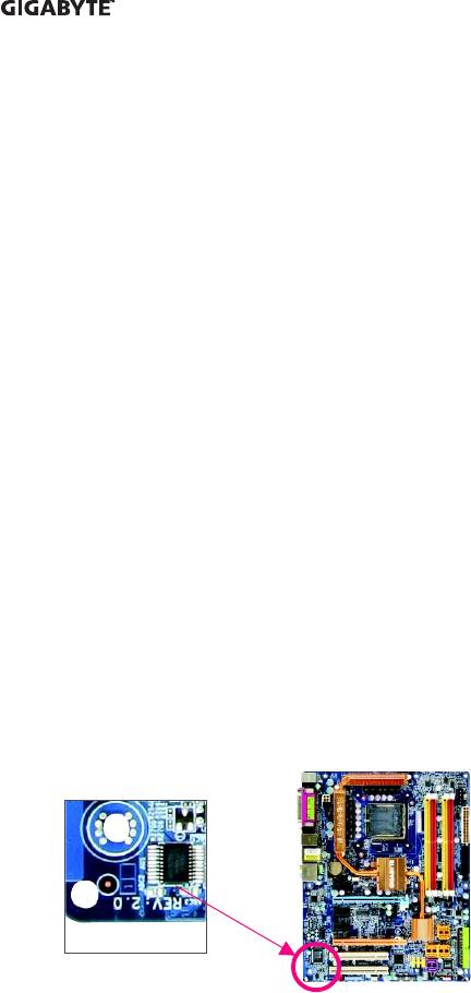
Identifying Your Motherboard Revision
The revision number on your motherboard looks like this: «REV: X.X.» For example, «REV: 1.0»
means the revision of the motherboard is 1.0. Check your motherboard revision before updating
motherboard BIOS, drivers, or when looking for technical information.
Example:

Table of Contents
Box Contents ………………………………………………………………………………………………….. 6
Optional Items ………………………………………………………………………………………………….. 6
GA-945GCM-S2L/GA-945GCM-S2C Motherboard Layout…………………………………….. 7
Block Diagram…………………………………………………………………………………………………. 8
Chapter 1 Hardware Installation ………………………………………………………………………… 9
1—1 Installation Precautions …………………………………………………………………………. 9
1—2 Product Specifications ………………………………………………………………………… 10
1—3 Installing the CPU and CPU Cooler…………………………………………………….. 13
1-3-1 Installing the CPU …………………………………………………………………………………… 13
1-3-2 Installing the CPU Cooler ……………………………………………………………………….. 15
1-4 Installing the Memory …………………………………………………………………………. 16
1-4-1 Dual Channel Memory Configuration………………………………………………………. 16
1-4-2 Installing a Memory………………………………………………………………………………… 17
1-5 Installing an Expansion Card ………………………………………………………………. 18
1-6 Back Panel Connectors ……………………………………………………………………… 19
1—7 Internal Connectors …..……………………………………………………………………….. 21
Chapter 2 BIOS Setup……………………………………………………………………………………. 31
2—1 Startup Screen …………………………………………………………………………………… 32
2-2 The Main Menu …………………………………………………………………………………. 33
2-3 Standard CMOS Features ………………………………………………………………….. 35
2—4 Advanced BIOS Features…………………………………………………………………… 37
2-5 Integrated Peripherals …………………………………………………………………………. 39
2-6 Power Management Setup ………………………………………………………………….. 43
2—7 PnP/PCI Configurations……………………………………………………………………… 45
2-8 PC Health Status ………………………………………………………………………………. 46
2—9 Frequency/Voltage Control ………………………………………………………………….. 48
2-10 Load Fail-Safe Defaults……………………………………………………………………….. 50
2—11 Load Optimized Defaults ……………………………………………………………………… 50
2-12 Set Supervisor/User Password…………………………………………………………… 51
2-13 Save & Exit Setup…………………………………………………………………………….. 52
2-14 Exit Without Saving …………………………………………………………………………… 52
— 4 —

Chapter 3 Drivers Installation ………………………………………………………………………….. 53
3-1 Installing Chipset Drivers ……………………………………………………………………. 53
3—2 Software Applications …………………………………………………………………………. 54
3-3 Driver CD Information ………………………………………………………………………… 54
3—4 Hardware Information …………………………………………………………………………. 55
3—5 Contact Us……………………………………………………………………………………….. 55
Chapter 4 Unique Features…………………………………………………………………………….. 57
4-1 Xpress Recovery2 …………………………………………………………………………….. 57
4—2 BIOS Update Utilities…………………………………………………………………………. 62
4-2-1 Updating the BIOS with the Q-Flash Utility……………………………………………… 62
4-2-2 Updating the BIOS with the @BIOS Utility ………………………………………………. 65
4-3 EasyTune 5………………………………………………………………………………………. 67
4-4 Windows Vista ReadyBoost………………………………………………………………… 68
Chapter 5 Appendix ………………………………………………………………………………………. 69
5—1 Configuring Audio Input and Output……………………………………………………….. 69
5-1-1 Configuring 2/4/5.1-Channel Audio…………………………………………………………. 69
5-1-2 Installing the S/PDIFOut Cable (Optional) ………………………………………………… 72
5-1-3 Configuring Microphone Recording …………………………………………………………. 74
5-1-4 Using the Sound Recorder……………………………………………………………………… 76
5-2 Troubleshooting ………………………………………………………………………………….. 77
5-2-1 Frequently Asked Questions ………………………………………………………………….. 77
5-2-2 Troubleshooting Procedure …………………………………………………………………….. 78
Regulatory Statements ……………………………………………………………………………………. 80
— 5 —
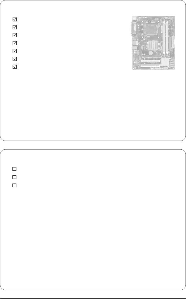
Box Contents
GA-945GCM-S2L or GA-945GCM-S2C motherboard
Motherboard driver disk
User’s Manual
Quick Installation Guide
One IDE cable and one floppy disk drive cable
Two SATA 3Gb/s cables
I/O Shield
• The box contents above are for reference only and the actual items shall depend on product package you obtain.
The box contents are subject to change without notice.
• The motherboard image is for reference only.
Optional Items
2-port USB 2.0 bracket (Part No. 12CR1-1UB030-51R)
2-port SATA power cable (Part No. 12CF1-2SERPW-01R)
S/PDIF out cable (Part No. 12CR1-1SPOUT-02R)
— 6 —
(Ocr-Read Summary of Contents of some pages of the Gigabyte GA-945GCM-S2L Document (Main Content), UPD: 16 August 2023)
-
44, 2-6 Power Management Setup CMOS Setup Utility-Copyright (C) 1984-2007 Award Software Power Management Setup ACPI Suspend Type Soft-Off by PWR-BTTN PME Event Wake Up Power On by Ring Resume by Alarm [SllgOS)] [Instant-Off] [Enabled] [Enabled] [Disabled] Item Help Menu Level* HPET Support HPET Mode < N °’« Power On By Mouse Power On By Keyboard [Enabled] [32-bit mode] I Disabled] I Disabled] AC Back Function -: Move Enter: Select F5: Previ…
-
41, Gigabyte GA-945GCM-S2L o- SATA Port 1/3 Set to >• This value is dependent on the On-Chip SATA Mode and PATA IDE Set to settings. When PATA IDE Set to is configured to Ch. 0 Master/Slave, this option will be automatically set to Ch. 1 Master/Slave. <r USB Controller Enables or disables the integrated USB controller. (Default: Enabled) Disabled will turn off all of the USB functionalities below, o- USB 2.0 Controller Enables or disables the integrated USB 2.0 controller. (Default: Enabl…
-
28, 10) F_PANEL (Front Panel Header) Connect the power switch, reset switch, speaker and system status indicator on the chassis front panel to this header according to the pin assignments below. Note the positive and negative pins before connecting the cables. • MSG (Message/Power/Sleep LED): Connects to the power status indicator on the chassis front panel. The LED is on when the system is operating. The LED keeps blinking when the system is in S1 sleep state. The LED is…
-
62, 4-2 BIOS Update Utilities GIGABYTE motherboards provide two unique BIOS update tools, Q-Flash™ and @BIOS™. GIGABYTE Q-Flash and @BIOS are easy-to-use and allow you to update the BIOS without the need to enter MS- DOS mode. What is Q-Flash™? 18 With Q-Flash you can update the system BIOS without having to enter operating systems like MS-DOS or Window first. Embedded in the BIOS, the Q-Flas…
-
82, Contact Us • Taiwan (Headquarters) GIGA-BYTE TECHNOLOGY CO., LTD. Address: No.6, Bau Chiang Road, Hsin-Tien, Taipei 231, Taiwan TEL:+886-2-8912-4888 FAX:+886-2-8912-4003 Tech. and Non-Tech. Support (Sales/Marketing): http://ggts.gigabyte.com.tw WEB address (English): http://www.gigabyte.com.tw WEB address (Chinese): http://www.gigabyte.tw • U.S.A. G.B.T. INC. TEL:+1-626-854-9338 FA…
-
71, В. Configuring Sound Effect: You may configure an audio environment on the Sound Effect tab. C. Configuring AC’97 Audio: If you want to connect an AC’97 front panel audio module, click the tool icon on the Audio I/O tab On the Global Connector Settings box, select the Dis- able front panel jack detection check box. Click OK to activiate the AC’97 functionality. *l • Bofc« a »•Z…
-
16, В. Follow the steps below to correctly install the CPU into the motherboard CPU socket. Before installing the CPU, make sure to turn off the computer and unplug the power { AU * I0 } cord from the power outlet to prevent damage to the CPU. Step 3: Lift the metal load plate on the CPU socket. Step 4: Hold the CPU with your thumb and index fingers. Align the CPU pin one marking (triangle) with the pin one corner of the CPU socke…
-
50, ^ CPU Host Frequency (Mhz) Allows you to manually set the CPU host frequency. This item is configurable only if the CPU Host Clock Control option is enabled. The adjustable range is from 100 MHz to 700 MHz. For an 533 MHz FSB CPU, set this item to 133 MHz. For an 800 MHz FSB CPU, set this item to 200 MHz. For a 1066 MHz FSB CPU, set this item to 266 MHz. For a 1333 MHz FSB CPU, set this item t…
-
43, ^ Onboard LAN Boot ROM Allows you to decide whether to activate the boot ROM integrated with the onboard LAN chip. (Default: Disabled) Onboard Serial Port 1 Enables or disables the first serial port and specifies its base I/O address and corresponding interrupt. Options are: Auto, 3F8/IRQ4 (default), 2F8/IRQ3, 3E8/IRQ4, 2E8/IRQ3, Disabled, o* Onboard Parallel Port Enables or disables the onboard parallel por…
-
36, 2-3 Standard CMOS Features CMOS Setup Utility-Copyright (C) 1984-2007 Award Software Standard CMOS Features Dale (mm:dd:yy) •vU Aug 6 2007 Item Help Time (hh:mm:ss) 10:31:24 Menu Level* • IDE Channel 0 Master • IDE Channel 0 Slave • IDE Channel 2 Master • IDE Channel 2 Slave • IDE Channel 3 Master • IDE Channel 3 Slave [None] [None] [None] [None] [None| [None) Drive A Floppy 3 Mode Support [1.44M, 3.5″] | Disabled] Halt On [AH, But Keyboard) …
-
33, Gigabyte GA-945GCM-S2L 2-1 Startup Screen The following screen may appear when the computer boots. Motherboard Model— BIOS Version, Function Keys Function Keys: <DEL> : BIOS Setup/Q-Flash Press the <Delete> key to enter BIOS Setup or to access the Q-Flash utility in BIOS Setup. <F9> : Xpress Recovery2 If you have ever entered Xpress Recovery2 to back up hard drive data using the motherboard driver disk, the <F9> key can be used for subsequent access to X…
-
73, Step 3: Connect a S/PDIF coaxial cable or a S/PDIF optical cable (either one) to an external decoder for transmitting the S/PDIF digital audio signals. B. Configuring S/PDIF out: Click the tool icon in the DIGITAL section. In the S/PDIF Settings dialog box, select an output sam pling rate and select (or disable) the output source Click OK to complete the configuration. — 73 — Appendix
… -
65, 4-2-2 Updating the BIOS with the @BIOS Utility A. Before You Begin: 1. In Windows, close all applications and TSR (Terminate and Stay Resident) programs. This helps prevent unexpected failures when performing a BIOS update. 2. During the BIOS update process, ensure the Internet connection is stable and do NOT interrupt the Internet connection (for example, avoid a power loss or switching off the Internet…
-
47, 2-8 PC Health Status CMOS Setup Utility-Copyright (C) 1984-2007 Award Software PC Health Status Reset Case Open Status [Disabled] Item Help OK Menu Level* CPU Warning Temperature [Disabled! CPU FAN Fail Warning [Disabled] SYSTEM FAN Fail Warning I Disabled] CPU Smart FAN Control I Enabled ] I Move Enter: Select +/-/PU/PD: Value F10: Save ESC: ixit F1 General Help F5: Previous Values F6: Fail-Safe Defaults F7: Optimized Defaults ^ Reset Case Open Status …
-
74, 5-1-3 Configuring Microphone Recording Step 1: After installing the audio driver, the Audio Manager icon jjJ will appear in your system tray. Double-click the icon to access the Audio Control Panel. Step 2: Connect your microphone to the Mic in jack (pink) on the back panel or the Line in jack on the front panel. Then configure the jack for microphone functionality. Note: The microphone functions on the front panel and back panel cannot be used at the same time. -Г Step 3: Lo…
-
66, Gigabyte GA-945GCM-S2L Step 3: First make sure the model name on the screen is correct, then click OK. Upon completion, restart your system. • If more than one model is present when doing Step 3 above, recomfirm your motherboard NOTE model. Updating the BIOS with an incorrect BIOS file could result in an unbootable system. • If the BIOS update file for your motherboard is not present on the @BIOS server site, please manually download the BIOS update file from GIGABYTE’S w…
На чтение 13 мин Просмотров 18 Опубликовано Обновлено
Содержание
- Схема подключения разъёмов передней панели компьютера (F_PANEL, F_AUDIO и F_USB)
- Как подключить usb к материнской плате gigabyte
- Расположение и маркировка портов
- USB 3.0 и прочие тонкости
- Подключение индикаторов и кнопок питания
- Подключение USB передней панели к материнской плате
- Подключение аудио передней панели к материнской плате
Схема подключения разъёмов передней панели компьютера (F_PANEL, F_AUDIO и F_USB)
Автор статьи: Шилин Алексей
Всем привет! В этой статье я наглядно покажу как правильно подключать кнопки (POWER, RESET) и устройства передней панели (F_PANEL, F_AUDIO и F_USB). Дело не хитрое, но стоит Вашего внимания.
В начале пару советов:
Разберу наглядно данное дело на старенькой материнской плате от фирмы Gigabyte модель GA-945GCM-S2C. Сразу скажу — Схемы подключения рисовал исключительно для данной статьи и на конкретном примере, цвета проводов у Вас будут отличаться. Главное понять и смысл подключения и воплотить (проверить) на своём ПК.

На этой картинке отображены разъёмы материнской платы для подключения коннекторов.
В основном (бывают исключения) под разъёмами мелким шрифтом написаны порядок подключения коннекторов и полярность. В моём случае указано:
PWR_LED (три разъемчика) — индикация включенного компьютера;
+PW- (PWRSW) — кнопка включения питания ПК;
-RES+ (RESET) — кнопка для перезагрузки ПК;
+HD- (IDE_LED, HDD_LED) — светодиод обращения к жесткому диску;
+SPEAK- (SPEAKER) — тот самый сигнал(ы), который издаёт компьютер при включении, если обнаружена ошибка.
Коннекторы выглядят так (см. скрины)

К каждому коннектрору подходят два провода:
В данном случае белые это минус «-» или Ground (земля) , а цветные «+». У коннектора SPEAKER (черный, красный) — чёрный «+», а красный «-«. Чтобы определить полярность коннекторов, достаточно его перевернуть на тыльную сторону — видим на против одного проводка маленький чёрный треугольник — это «+».
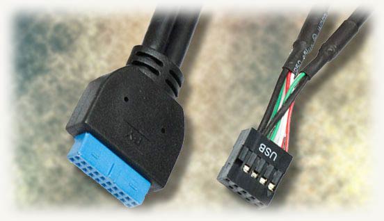
Переходим к следующему этапу, подключение передних дополнительных USB — разъёмов и картридера в разъёмы F_USB2 и F_USB1 (разницы нет, но лучше начинать по порядку). Если уже коннектор «спаянный», т.е. все проводки собраны в одну колодку — процесс значительно упрощается.
Просто подключаем этот «большой» коннектор состоящий из: восьми проводков, одного пустого и одного запаянного разъёма (всего десять) таким образом, чтобы ПУСТОЙ разъемчик совпал с ЗАПАЯННЫМ гнездом в коннекторе. (см. скрины)

А, вот если у Вас пучок проводов как на картинке — нарисую наглядную схемку:)

Здесь мы видим: POWER (Питание — 2 шт.), GND (Ground — «земля» 2шт.), D3+ (плюс), D3- (минус) на один порт usb и D2+ (плюс), D2- (минус) на другой порт. Как Вы уже догадались, два коннектора POWER идентичны и их можно менять местами между собой, так же как и GND. Главное не перепутать местами POWER и GND.

Так теперь осталось разобраться с подключением F_AUDIO разъемов для микрофона и наушников.
Опять же, если Вам повезло и от передней панели идёт большая колодка с 10-ью гнездами, просто вставляем (тут точно не ошибетесь). У меня случай поинтереснее. ) А, именно такие коннекторы: SPK R (выход правого канала на переднюю панель), SPK L (выход левого канала на переднюю панель), MIC (выход микрофона на переднюю панель) и GND.


Вот и всё подключено. Спасибо за внимание, удачи.
Если у Вас отличаются провода, названия коннекторов (колодок) и тд. и тп. не ленитесь, скачайте с официального сайта производителя Вашей материнской платы мануал (руководство) и там 99% найдёте схемы подключения всех F_PANEL, F_AUDIO и F_USB.
Черный экран windows 7 — Узнайте как избавиться от черного экрана Windows 7.
Восстановление windows 7 — Как произвести восстановление системы Windows 7.
Как активировать windows 7 — Как легально активировать windows 7.
Источник
Как подключить usb к материнской плате gigabyte
Автор статьи: Шилин Алексей
Всем привет! В этой статье я наглядно покажу как правильно подключать кнопки (POWER, RESET) и устройства передней панели (F_PANEL, F_AUDIO и F_USB). Дело не хитрое, но стоит Вашего внимания.
В начале пару советов:
Разберу наглядно данное дело на старенькой материнской плате от фирмы Gigabyte модель GA-945GCM-S2C. Сразу скажу – Схемы подключения рисовал исключительно для данной статьи и на конкретном примере, цвета проводов у Вас будут отличаться. Главное понять и смысл подключения и воплотить (проверить) на своём ПК.
На этой картинке отображены разъёмы материнской платы для подключения коннекторов.
В основном (бывают исключения) под разъёмами мелким шрифтом написаны порядок подключения коннекторов и полярность. В моём случае указано:
PWR_LED (три разъемчика) – индикация включенного компьютера;
+PW- (PWRSW) – кнопка включения питания ПК;
-RES+ (RESET) – кнопка для перезагрузки ПК;
+HD- (IDE_LED, HDD_LED) – светодиод обращения к жесткому диску;
+SPEAK- (SPEAKER) – тот самый сигнал(ы), который издаёт компьютер при включении, если обнаружена ошибка.
Коннекторы выглядят так (см. скрины)
К каждому коннектрору подходят два провода:
В данном случае белые это минус «-» или Ground (земля) , а цветные «+». У коннектора SPEAKER (черный, красный) – чёрный «+», а красный «-«. Чтобы определить полярность коннекторов, достаточно его перевернуть на тыльную сторону – видим на против одного проводка маленький чёрный треугольник – это «+».
Переходим к следующему этапу, подключение передних дополнительных USB – разъёмов и картридера в разъёмы F_USB2 и F_USB1 (разницы нет, но лучше начинать по порядку). Если уже коннектор «спаянный», т.е. все проводки собраны в одну колодку – процесс значительно упрощается.
Просто подключаем этот «большой» коннектор состоящий из: восьми проводков, одного пустого и одного запаянного разъёма (всего десять) таким образом, чтобы ПУСТОЙ разъемчик совпал с ЗАПАЯННЫМ гнездом в коннекторе. (см. скрины)
А, вот если у Вас пучок проводов как на картинке – нарисую наглядную схемку:)
Здесь мы видим: POWER (Питание – 2 шт.), GND (Ground – «земля» 2шт.), D3+ (плюс), D3- (минус) на один порт usb и D2+ (плюс), D2- (минус) на другой порт. Как Вы уже догадались, два коннектора POWER идентичны и их можно менять местами между собой, так же как и GND. Главное не перепутать местами POWER и GND.
Так теперь осталось разобраться с подключением F_AUDIO разъемов для микрофона и наушников.
Опять же, если Вам повезло и от передней панели идёт большая колодка с 10-ью гнездами, просто вставляем (тут точно не ошибетесь). У меня случай поинтереснее. ) А, именно такие коннекторы: SPK R (выход правого канала на переднюю панель), SPK L (выход левого канала на переднюю панель), MIC (выход микрофона на переднюю панель) и GND.
Вот и всё подключено. Спасибо за внимание, удачи.
Если у Вас отличаются провода, названия коннекторов (колодок) и тд. и тп. не ленитесь, скачайте с официального сайта производителя Вашей материнской платы мануал (руководство) и там 99% найдёте схемы подключения всех F_PANEL, F_AUDIO и F_USB.
Черный экран windows 7 – Узнайте как избавиться от черного экрана Windows 7.
Восстановление windows 7 – Как произвести восстановление системы Windows 7.
Как активировать windows 7 – Как легально активировать windows 7.
Привет, друзья! Интерфейс USB прочно закрепился в жизни любого пользователя компьютера. Благодаря универсальности и простоте использования, с его помощью можно подключить массу устройств – настольную лампу, вентилятор, геймпад, игровой руль, флешку, внешний винчестер и многое другое.
Частое использование портов, расположенных с тыльной стороны, не всегда удобно, так как доступ к ним может быть затруднен. На текущий момент большинство корпусов оборудованы портами ЮСБ на передней панели, количество которых может отличаться в зависимости от модели.
В сегодняшней публикации я расскажу, как подключить USB разъемы на материнской плате правильно и что при этом следует учитывать. В конце поста вы найдете небольшой отрезок видео с инструкцией на эту тему.
Расположение и маркировка портов
Современные материнки чаще всего оборудованы четырьмя, шестью или восемью такими портами. Как правило, два или четыре из них наглухо впаяны таким образом, чтобы доступ к ним можно было получить с задней панели – там, где находятся гнезда для подключения клавиатуры и мышки, аудиовыходы и все остальное.
Прочие порты, расположены на самой «матери» и представляют собой разъемы с торчащими штырьками. Для подключения фронтальных портов к материнке используются специальные коннекторы. С их же помощью (и также к ЮСБ порту на материнской плате) подключается картридер, если он конечно есть.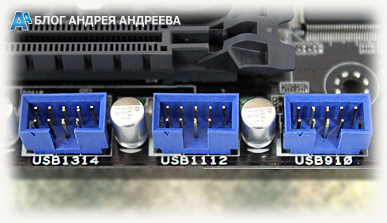 У такого коннектора отсутствует одно гнездо в левом нижнем углу. То есть там, где должно быть 10 отверстий, их всего 9. Благодаря этому, несложно понять, как именно подключить к штекеру на материнке этот коннектор.
Чтобы подключить внешний порт, нужно аккуратно насадить штекер на коннектор до упора. Постарайтесь не делать резких движений влево‐вправо, так как можно сломать один или несколько штырьков, что приведет к неработоспособности этого порта и вам придется задействовать следующий.
На «мамке» эти порты чаще всего расположены возле интерфейсов SATA и маркируются аббревиатурой USB с порядковым номером. Что именно и куда подключать, нет совершенно никакой разницы – порты работают параллельно.
USB 3.0 и прочие тонкости
Однако это справедливо в случаях, если используются порты одного поколения.
В случае, если на материнке есть второй, и третьей ревизии, и аналогичная ситуация наблюдается с фронтальной панелью, необходимо соответствие: USB 3.0 следует подключать только к соответствующему слоту на материнке, иначе он будет работать на скорости USB 2.0.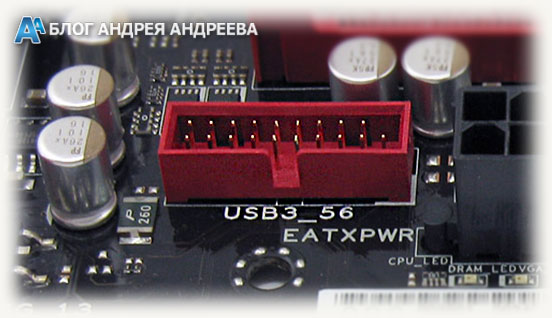 По поводу распиновки не стоит беспокоиться: она одинаковая у обеих ревизий. Кроме того, производители материнских плат – ASUS, MSI, Gigabyte, Asrock и менее крупные компании, соблюдают одинаковую распиновку, которой придерживаются и производители корпусов.
Однако учитывайте, что в редких случаях она все же может отличаться от общепринятой. Уточнить необходимую информацию можно в документации к материнской плате.
Не стоит беспокоиться, что можно подключить ЮСБ порт неправильно – в этом случае он попросту не будет работать. К счастью, сломать таким образом компьютер невозможно.
Также на эту тему советую почитать как подключить правильно жесткий диск , а также два винчестера на одном компьютере . О подключении передних аудио разъемов к материнской плате, вы можете узнать здесь .
А если вдруг что‐то забыли купить для своего железного друга, то огромный выбор комплектующих и периферии вы можете найти в этом популярном интернет‐магазине .
Спасибо за внимание, друзья, и не забывайте делиться моими постами в социальных сетях. До завтра!
p, blockquote 15,0,0,0,0 –> p, blockquote 16,0,0,0,1 –>
В этой статье вы узнаете, как подключить переключатель питания, сброса и светодиоды, а также аудио и USB-порты к материнской плате. Прежде чем пытаться соединить их, очень важно знать место, и полярность подключения. Для этого необходимо найти схемы в руководстве по материнской плате, которые подскажут вам точно, где находится каждый набор контактов на материнской плате или воспользоваться информацией в этой статье.
Подключение индикаторов и кнопок питания
Компьютерный корпус имеет кнопки для управления питания которые подключаются к материнской плате, и светодиоды для обозначения деятельности материнской платы. Вы должны подключить эти кнопки и индикаторы к материнской плате с помощью проводов из передней части корпуса показанные на рисунке №1, в разъеме на материнской плате (рис. №2). Надпись на материнской плате возле разъема панели показывает место подключения каждого провода и полярность каждого из них однако надписи с обозначениями присутствуют не всегда на материнской плате.
Найдите в компьютерном корпусе разъемы передней панели (см. рис. 1). Далее находим разъём на материнской плате обычно он находится внизу материнской платы, и подписан надписью PANEL1 или JFP1, он может быть в разном исполнении(см. рис. 2.0, 2.1).
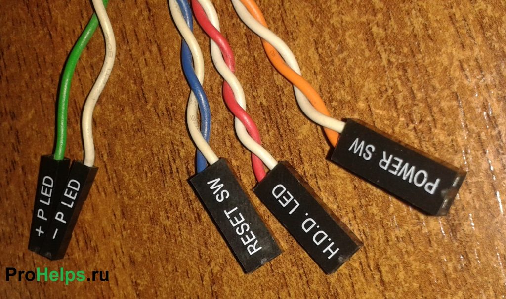 Рис. №1. Разъемы передней панели.
 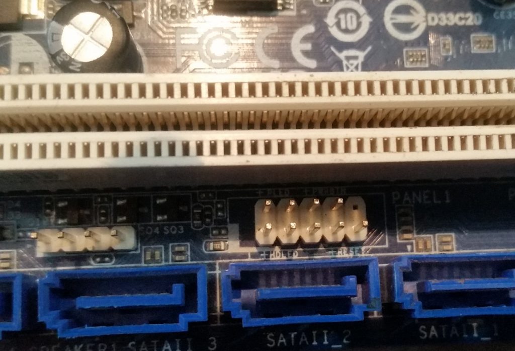 Рис № 2.0. Разъем передней панели на материнской плате.
 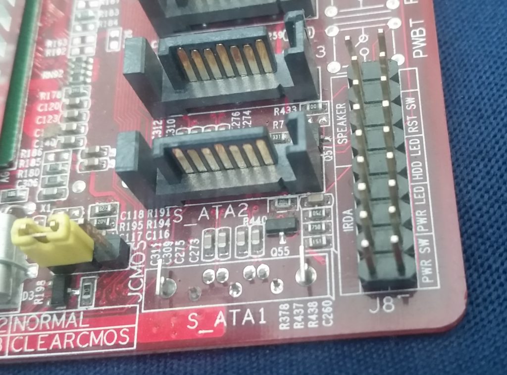 Рис № 2.1. Разъем передней панели на материнской плате.
Группа системных кабелей, показанных на картинке №1 имеют два провода, которые имеют цветовую маркировку. Черный или белый провод это земля (GND), а провода других цветов(красный, синий, зелёный, оранжевый) это питание. Подключение осуществляется с лева на право, при подключении Все плюсовые контакты всегда будут находиться слева кроме кнопки reset, однако полярность кнопок неважна так как кнопки при нажатии замыкают контакты.
Просто установите эти провода к разъему с тем же именем на материнской плате соблюдая полярность светодиодов.
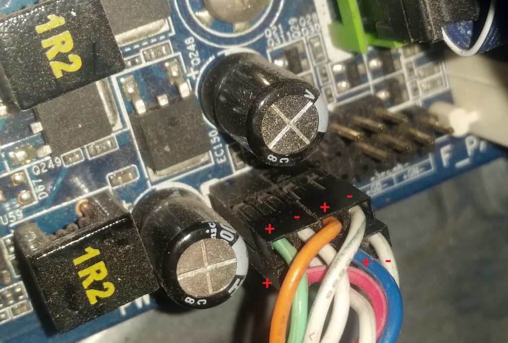 Рис № 2.2. Полярность проводов передней панели.
Ниже перечислены возможные сокращенные имена для них, которые будут записаны на самих соединителях.
PWR-SW, PW SW, PW = Кнопка питания (Power Switch)(не требуется полярность). Элемент управления кнопка питания, которая позволяет включать и выключать компьютер.
PWR-LED, P-LED, MSG = Светодиод питания (Power LED)(требуется полярность). Индикатор показывает когда компьютер включен или находится в режиме ожидания.
RES-SW, R-SW, RES = Переключатель сброса (Reset Switch) (не требуется полярность). Кнопка сброса для перезагрузки компьютера.
HDD-LED, HD = Светодиодный индикатор жесткого диска (Hard Disk Drive LED)(требуется полярность). Этот индикатор мигает при записи и чтении информации с жесткого диска.
SPK, SPKR, SPEAK = Внутренний динамик (Speaker)(требуется полярность), используемый для озвучивания звуковых сигналов, которые вы слышите от компьютера при загрузке.
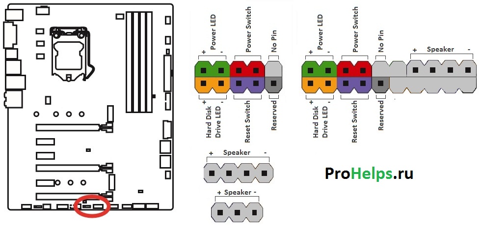 Рис № 3. Распиновка контактов передней панели на материнской плате
Подключение USB передней панели к материнской плате
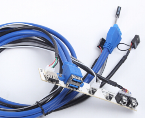
Для начала находим разъём USB на материнской плате, обычно он находится внизу материнской платы и подписан надписью F_USB или USB. Так же на каждом проводном разъеме(Рис №4.0) можно прочитать его значение, которое может быть +5V (или VCC или Power), D+, D – и GND.
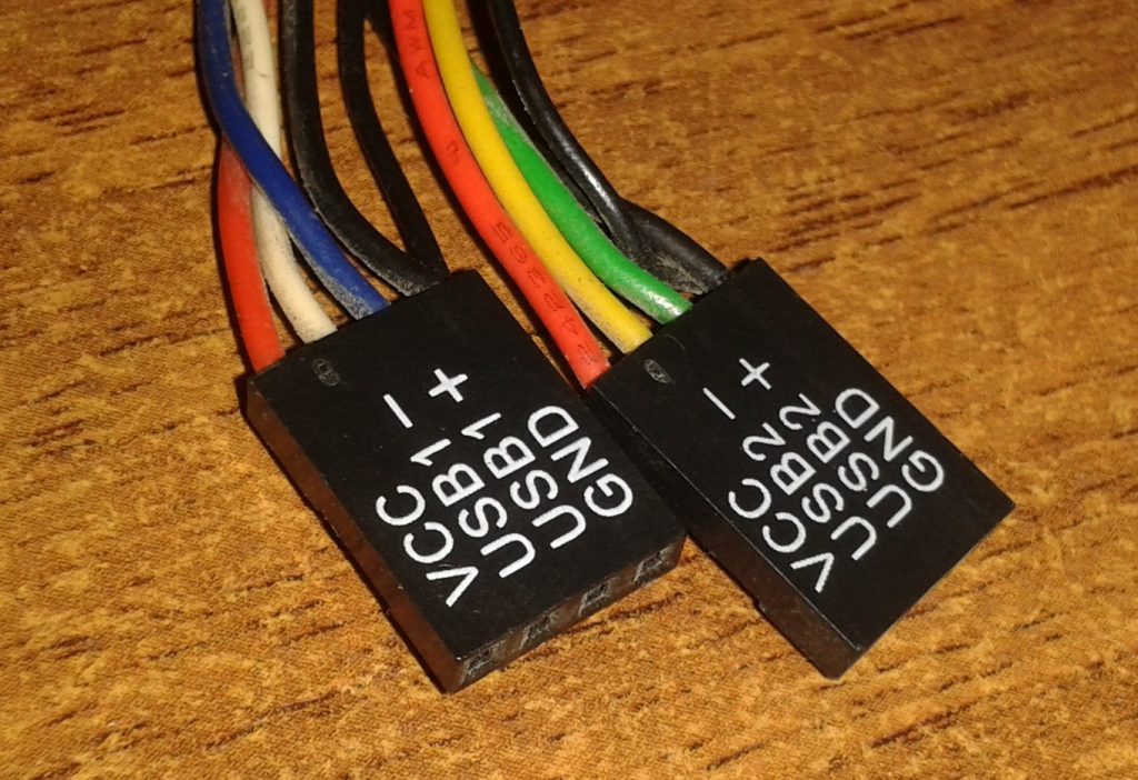 Рис № 4.0. Полярность USB.
Далее необходимо просто установить каждый из проводов (+5V, D+, D – и GND) в нужное место на материнской плате, как показано на Рис.4.2.
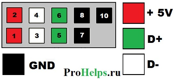 Рис №4.1. Подключение USB 2.0 передней панель к материнской плате.
 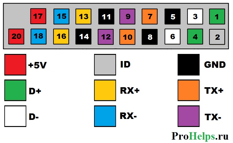 Рис №4.2. Подключение USB 3.0 передней панель к материнской плате.
 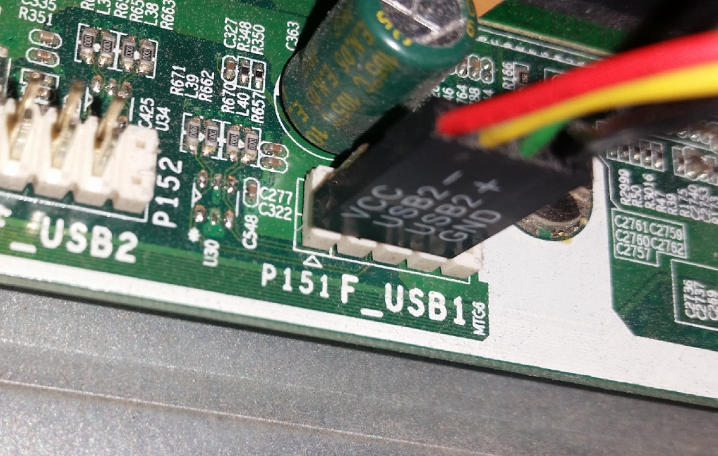 Рис №4.3. Подключение USB 2.0 к материнской плате.
Подключение аудио передней панели к материнской плате
Чтобы использовать эти разъемы, ваша материнская плата должна иметь встроенную звуковую карту (другими словами, встроенный звук). Однако установка не так проста, как кажется, и в сегодняшней колонке мы объясним, как это нужно сделать.
В конце каждого провода имеется небольшой черный разъем, и в этом разъеме мы можем прочитать функцию провода. Вы найдете следующие провода: Mic In (или Mic Data), Ret L, Ret R, L Out (или Ear L), R Out (или Ear R) и два Gnd (или Ground). Если вы внимательно посмотрите, то увидите провода Ret L и L Out подключены друг к другу, то же самое происходит между проводами Ret R и R Out.
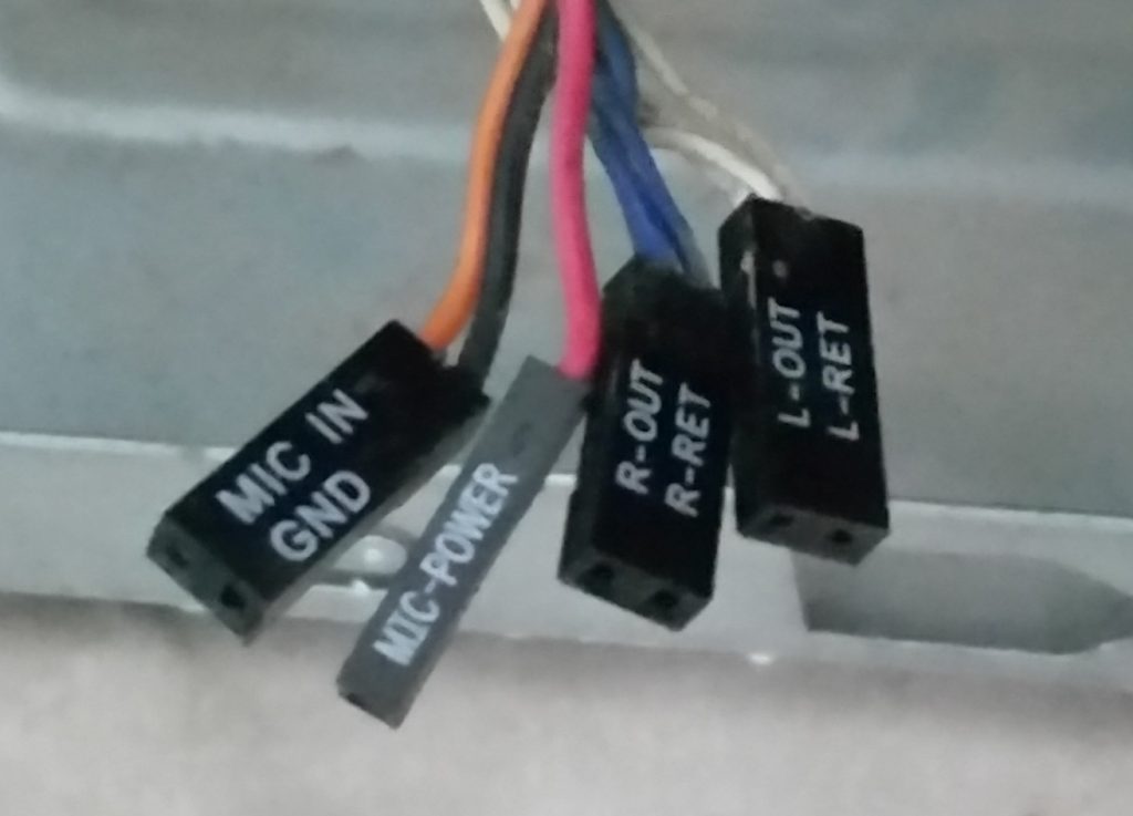 Рис №5.0. Подключение аудио к материнской плате.
Вы должны найти место установки таких проводов в вашей материнской плате. Это место обозначается как Audio, External Audio, Ext Audio, Front Audio, F Audio, HD Audio или что-то в этом роде. Это разъем состоит из 9-контактного разъема, и есть два перемычки, которые устанавливают соединение некоторых из этих контактов. Точное положение этого разъема варьируется в зависимости от модели материнской платы.
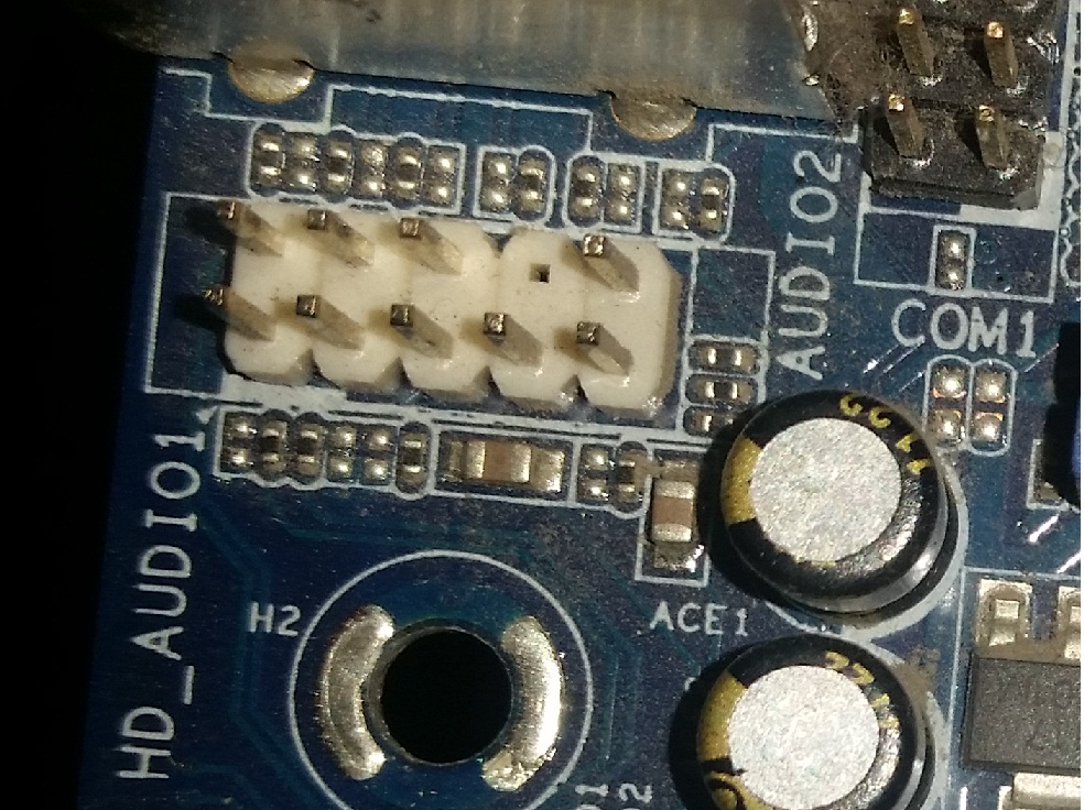 Рис №5.1. Вид штекера аудио на материнской плате.
Для установки проводов первым шагом является понимание системы нумерации штырей разъема материнской платы. В разъеме есть девять контактов, но разъем считается 10-контактным, потому что один из контактов был удален (контакт 8). Перемычки соединяют контакты 5 и 6 и 9 и 10. Поскольку имеется пространство без штифта (контакт 8), легко обнаружить нумерацию других контактов.
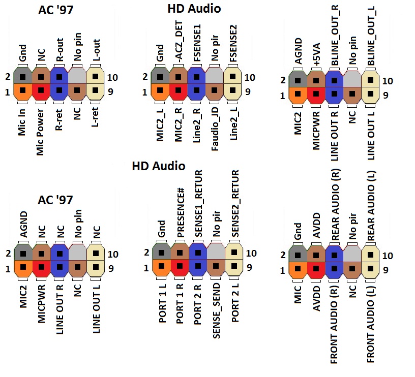 Рис №5.2. Распиновка аудио на материнской плате.
Удалите перемычки. Подключение проводов должно быть выполнено следующим образом: Mic In to pin 1; Gnd — контакты 2 и 3; R Вывести на вывод 5; Ret R для вывода 6; L Вывод на контакт 9, а Ret L — на контакт 10.
Источник