Давненько искал я книгу по самостоятельному ремонту.
Купил уже давно, но в сети нашел еще одну, немного по другому описание сделано, но вариант не плохой.
Хочу поделиться с вами, так как в поиске не нашел чтобы кто выложил книгу по конекту. Может кому и поможет разобраться с какими-то сложными узлами или почерпнет что-то полезное от советов производителя.
Описание:
FORD Tourneo/Transit CONNECT
В этом руководстве:все модели с бензиновым и дизельными двигателями 1.8 л, оборудованные 5-ступенчатой РКПП.
Сотни иллюстраций показывают органы управления и отдельные этапы работ. Разделы, посвященные быстрому и простому поиску неисправностей, помогают в устранении неполадок. Электрические схемы помогают быстро обнаружить неисправности в электрической системе и облегчают установку дополнительного оборудования.
Здесь Вы найдете данные по ремонту:
двигателя
системы питания
системы выпуска отработавших газов
сцепления
коробки передач
подвесок
рулевого управления
тормозов
колес и шин
кузова
электрооборудования
а также рекомендации по техническому обслуживанию и диагностике электронных систем управления.
Отдельная глава предназначена для знакомства владельца автомобиля с органами управления и приемами эксплуатации.
Ссылка для скачивания
Ещё одна ссылка на Гугл диск. Если по той не качает.
drive.google.com/file/d/1…kLwZWkU/view?usp=drivesdk
Цена вопроса: 0 ₽
Руководство на английском языке по ремонту и эксплуатации Ford Tourneo Connect и Ford Transit Connect 2002 года выпуска.
- Автор: —
- Издательство: —
- Год издания: —
- Страниц: 2797
- Формат: PDF
- Размер: 170,1 Mb
Руководство по эксплуатации и ремонту Ford Tourneo Connect и Ford Transit Connect с 2003 года выпуска с бензиновыми и дизельными двигателями.
- Автор: —
- Издательство: Монолит
- Год издания: —
- Страниц: 404
- Формат: —
- Размер: —
Руководство по эксплуатации и ремонту автомобилей Ford Tourneo Connect и Ford Transit Connect с 2003 года выпуска с бензиновыми и дизельными двигателями.
- Автор: —
- Издательство: Монолит
- Год издания: —
- Страниц: 412
- Формат: —
- Размер: —
Руководство по эксплуатации и ремонту Ford Tourneo Connect и Ford Transit Connect с 2013 года выпуска с бензиновыми и дизельными двигателями.
- Автор: —
- Издательство: Монолит
- Год издания: —
- Страниц: 400
- Формат: —
- Размер: —
Подборка руководств по эксплуатации Ford Tourneo Connect и Ford Transit Connect 2006-2013 годов выпуска.
- Автор: —
- Издательство: Ford Motor Company
- Год издания: 2006-2013
- Страниц: —
- Формат: PDF
- Размер: 64,2 Mb
Подборка руководств по эксплуатации Ford Transit Connect 2013-2014 годов выпуска.
- Автор: —
- Издательство: Ford Motor Company
- Год издания: 2013/2014
- Страниц: 364/376
- Формат: PDF
- Размер: 30,1 Mb
Руководство по техническому обслуживанию и ремонту Ford Tourneo Connect и Ford Transit Connect с 2002 года выпуска.
- Автор: И.А. Карпов
- Издательство: Арус
- Год издания: 2008
- Страниц: 310
- Формат: —
- Размер: —

-
Contents
-
Table of Contents
-
Bookmarks
Quick Links
2010 Transit Connect (tst)
Owners Guide (own2002), 1st Printing
USA (fus)
Table of Contents
4
12
12
17
20
20
21
23
25
35
35
37
38
38
41
42
50
50
51
53
54
55
61
61
66
1
Related Manuals for Ford 2010 Transit Connect
Summary of Contents for Ford 2010 Transit Connect
-
Page 1: Table Of Contents
Lights Headlamps Turn signal control Bulb replacement Driver Controls Windshield wiper/washer control Steering wheel adjustment Power windows Mirrors Speed control Locks and Security Keys Anti-theft system 2010 Transit Connect (tst) Owners Guide (own2002), 1st Printing USA (fus) Table of Contents…
-
Page 2
Table of Contents Seating and Safety Restraints Seating Safety restraints Airbags Child restraints Tires, Wheels and Loading Tire information Tire inflation Tire Pressure Monitoring System (TPMS) Vehicle loading Trailer towing Recreational towing Driving Starting Brakes AdvanceTrac Transmission operation Reverse sensing system Roadside Emergencies Getting roadside assistance Hazard flasher control… -
Page 3
Ford Motor Company. Ford may change the contents without notice and without incurring obligation. Copyright © 2009 Ford Motor Company… -
Page 4: Introduction
Introduction CONGRATULATIONS Congratulations on acquiring your new Ford. Please take the time to get well acquainted with your vehicle by reading this handbook. The more you know and understand about your vehicle, the greater the safety and pleasure you will derive from driving it.
-
Page 5
Warning symbols on your vehicle When you see this symbol, it is imperative that you consult the relevant section of this guide before touching or attempting adjustment of any kind. Protecting the environment We must all play our part in protecting the environment. -
Page 6
Using your vehicle as an ambulance Do not use this vehicle as an ambulance. Your vehicle is not equipped with the Ford Ambulance Preparation Package. -
Page 7
In order to properly diagnose and service your vehicle, Ford Motor Company, Ford of Canada, and service and repair facilities may… -
Page 8
Introduction may seek to access the information independently of Ford Motor Company and Ford of Canada. To the extent that any law pertaining to Event Data Recording applies to SYNC or its features, please note the following: Once 911 Assist (if equipped) -
Page 9
WARNING: Driving while distracted can result in loss of vehicle control, accident and injury. Ford strongly recommends that drivers use extreme caution when using any device that may take their focus off the road. The driver’s primary responsibility is the safe operation of their vehicle. -
Page 10
Introduction These are some of the symbols you may see on your vehicle. Safety Alert Fasten Safety Belt Airbag — Side Child Seat Tether Anchor Anti-Lock Brake System Brake Fluid — Non-Petroleum Based Stability Control System Master Lighting Switch Fog Lamps-Front Fuel Pump Reset Windshield Defrost/Demist… -
Page 11
Power Windows Front/Rear Child Safety Door Lock/Unlock Panic Alarm Engine Coolant Do Not Open When Hot Avoid Smoking, Flames, or Sparks Explosive Gas Power Steering Fluid Service Engine Soon Passenger Compartment Air Filter Check Fuel Cap Vehicle Symbol Glossary Power Window Lockout Interior Luggage Compartment Release Engine Oil… -
Page 12: Instrument Cluster
Instrument Cluster WARNING LIGHTS AND CHIMES Warning lights and gauges can alert you to a vehicle condition that may become serious enough to cause expensive repairs. A warning light may illuminate when a problem exists with one of your vehicle’s functions. Many lights will illuminate when you start your vehicle to make sure the bulb works.
-
Page 13
WARNING: Under engine misfire conditions, excessive exhaust temperatures could damage the catalytic converter, the fuel system, interior floor coverings or other vehicle components, possibly causing a fire. Brake system warning light: To confirm the brake system warning light is functional, it will momentarily illuminate when the ignition is turned to the on position when the engine is not running, or in a position between on and start, or… -
Page 14
Instrument Cluster Safety belt: Reminds you to fasten your front driver and passenger safety belt. A Belt-Minder chime will also sound to remind you to fasten your safety belt. Refer to the Seating and Safety Restraints chapter to activate/deactivate the Belt-Minder chime feature. -
Page 15
Instrument Cluster Low tire pressure warning: Illuminates when your tire pressure is low. If the light remains on at start up or while driving, the tire pressure should be checked. Refer to Inflating your tires in the Tires, Wheels and Loading chapter. When the ignition is first turned to on, the light will illuminate for three seconds to ensure the bulb is working. -
Page 16
Instrument Cluster Headlamps: Illuminates when the low–beam headlamps are turned on. Rear fog lamps: Illuminates when the rear fog lamps are turned on. Key-in-ignition warning chime: Sounds when the key is left in the ignition in the off or accessory position and the driver’s door is opened. Park warning chime: Sounds when the transmission is not in Park, the driver’s door is opened and the ignition is off or in accessory position. -
Page 17: Gauges
Instrument Cluster GAUGES Speedometer: Indicates the current vehicle speed. Tachometer: Indicates the engine speed in revolutions per minute. Driving with your tachometer pointer continuously at the top of the scale may damage the engine.
-
Page 18
Instrument Cluster Engine coolant temperature gauge: Indicates engine coolant temperature. At normal operating temperature, the needle will be in the normal range. If it enters the red section, the engine is overheating. Stop the vehicle as soon as safely possible, switch off the engine and let the engine cool. -
Page 19
Information display 1. Distance to empty / clock: Registers the approximate distance the vehicle can travel before refuelling is necessary. Clock shows the current set time. Switching the display between “clock” and “distance to empty”: • Vehicles with “clock” displayed normally: Press the Select button (4) to switch to the “distance to empty”… -
Page 20: Entertainment Systems
AM/FM stereo (if equipped) WARNING: Driving while distracted can result in loss of vehicle control, accident and injury. Ford strongly recommends that drivers use extreme caution when using any device that may take their focus off the road. The driver’s primary responsibility is the safe operation of their vehicle.
-
Page 21: Am/Fm Stereo With Cd
AM/FM stereo with single CD (if equipped) WARNING: Driving while distracted can result in loss of vehicle control, accident and injury. Ford strongly recommends that drivers use extreme caution when using any device that may take their focus off the road. The driver’s primary responsibility is the safe operation of their vehicle.
-
Page 22
Entertainment Systems Setting the clock To set the time or date, turn the radio on and press CLOCK until the time begins to flash. Press to access the desired selection (date or time). Once the desired selection is flashing, turn the VOL (Volume) control to adjust the time or date forward/backward. -
Page 23: Auxiliary Input Jack (Line In)
Auxiliary input jack (Line in) WARNING: Driving while distracted can result in loss of vehicle control, accident and injury. Ford strongly recommends that drivers use extreme caution when using any device that may take their focus off the road. The driver’s primary responsibility is the safe operation of their vehicle.
-
Page 24
Entertainment Systems The auxiliary input jack allows you to connect your portable music player and play music through the vehicle speakers with high fidelity. Required equipment: 1. Any portable music player designed to be used with headphones 2. An audio extension cable with stereo male 1/8 in. -
Page 25: Bluetooth System
portable music players have different output levels, so not all players should be set at the same levels. Some players will sound best at full volume and others will need to be set at a lower volume. 3. If the music sounds distorted at lower listening levels, turn the portable music player volume down.
-
Page 26
Bluetooth discovery mode. 6. Select FORD AUDIO when it appears in your phone’s display. 7. Enter the code number shown on the vehicle display using the phone keypad. If no code number is shown on the display, enter the Bluetooth PIN number 0000 or any number using the phone keypad. -
Page 27
Voice recognition Your Bluetooth system is equipped with a voice recognition system which allows you to perform some operations by speaking certain commands to the system. The system will respond with a series of beeps, confirmations or questions when necessary. At any time, you can say, “Cancel”… -
Page 28
Entertainment Systems Microphone Your vehicle has a microphone located in the A-pillar for the hands-free phone features and voice commands. To mute the microphone: During an active call, press < or > on the audio system. Press again to un-mute and return to normal function. -
Page 29
CD player voice commands Press the VOICE button on the stalk. After the tone, say, “CD player” and then any of the following commands: • Play • Shuffle all • Shuffle off • Repeat track • Help Can be used as a shortcut. Only available as a voice command if the CD contains audio data files such as .mp3 or .wma. -
Page 30
Entertainment Systems Phone voice commands Press the VOICE button on the stalk. After the tone, say, “Phone” and then any of the following commands: • Mobile name • Dial number • Delete directory • Store name* • Accept calls • Help Can be used as a shortcut. -
Page 31
Entertainment Systems Making a call using voice commands To make a hands-free call using your system: 1. Press the VOICE button on the stalk. 2. When the tone sounds, say, “Phone”. The system will confirm you are in phone mode. 3. -
Page 32
Entertainment Systems To accept the incoming call, press the system. To reject the incoming call, by pressing CD or AM/FM on the audio system. Redialing a number To redial a number: 1. Press on the audio system to enter the phone menu. 2. -
Page 33
3. Press < or > on the audio system to scroll through the list of paired (bonded) phones. 4. When the desired selection appears in the display that you would like to delete, press MENU. GENERAL AUDIO INFORMATION Radio frequencies: AM and FM frequencies are established by the Federal Communications Commission (FCC) and the Canadian Radio and Telecommunications Commission (CRTC). -
Page 34
CD units are designed to play commercially pressed 4.75 in (12 cm) audio compact discs only. Due to technical incompatibility, certain recordable and re-recordable compact discs may not function correctly when used in Ford CD players. Do not use any irregular shaped CDs or discs with a scratch protection film attached. -
Page 35: Climate Controls
Climate Controls MANUAL HEATING AND AIR CONDITIONING SYSTEM 1. Temperature control: Controls the temperature of the airflow in the vehicle. For optimum defrosting performance, set the dial to the defrost symbol 2. Air flow selections: Controls the direction of the airflow in the vehicle.
-
Page 36
Climate Controls Recirculated air: Press to activate/deactivate air recirculation in the vehicle cabin. Recirculated air may reduce the amount of time required to cool down the interior of the vehicle and may also help reduce undesired odors from reaching the interior of the vehicle. Recirculated air will not function in 5. -
Page 37: Rear Window Defroster
Climate Controls To aid in side window defogging/demisting in cold weather: 1. Select 2. Select A/C. 3. Adjust the temperature control to maintain comfort. 4. Set the fan speed to the highest setting. 5. Direct the outer instrument panel vents towards the side windows. To increase airflow to the outer instrument panel vents, close the vents located in the middle of the instrument panel.
-
Page 38: Lights
Lights HEADLAMP CONTROL Turns the lamps off. Turns on the parking lamps, instrument panel lamps, license plate lamps and tail lamps. Turns the headlamps on. Rear fog lamp The headlamp control also operates the rear fog lamp. The rear fog lamp can only be turned on when the headlamp control is in position.
-
Page 39: Headlamps
Lights High beams Pull the lever toward you to the second detent to activate the high beams. Pull the lever again toward you to the second detent to deactivate. Flash to pass Pull the lever toward you to the first detent to activate flash to pass, and release to deactivate.
-
Page 40
Lights VERTICAL AIM ADJUSTMENT 1. Park the vehicle directly in front of a wall or screen on a level surface, approximately 25 feet (7.6 meters) away. • (1) 8 feet (2.4 meters) • (2) Center height of lamp to ground •… -
Page 41: Turn Signal Control
TURN SIGNAL CONTROL • Push down to activate the left turn signal. • Push up to activate the right turn signal. INTERIOR LAMPS Dome lamps The dome lamp is equipped with a control switch that will illuminate when: • the doors are closed and the switch is in the right position.
-
Page 42: Bulb Replacement
Lights BULB REPLACEMENT Lamp assembly condensation Exterior lamps are vented to accommodate normal changes in pressure. Condensation can be a natural by-product of this design. When moist air enters the lamp assembly through the vents, there is a possibility that condensation can occur when the temperature is cold.
-
Page 43
Lights Replacing interior bulbs Check the operation of all bulbs frequently. Replacing front dome lamps 1. Make sure the headlamp switch is in the off position. 2. Switch off the interior lamps. 3. Pry out the light assembly with a flat screwdriver. -
Page 44
Lights Replacing reading bulbs 1. Open the reading lamp assembly. 2. Pull the bulb straight out and replace it. 3. After the bulb has been replaced, close the lamp assembly. Install in reverse order. Replacing exterior bulbs Check the operation of all bulbs frequently. Replacing headlamp bulbs 1. -
Page 45
Lights Replacing front parking lamp bulbs 1. Make sure the headlamp control is in the off position. 2. Turn the cover counterclockwise and remove it. 3. Remove the bulb and the bulb socket. 4. Pull the bulb straight out. Install in reverse order. -
Page 46
Lights Replacing front turn signal bulbs 1. Make sure the headlamp control is in the off position and open the hood. 2. Remove the bulb socket from the lamp assembly by turning it counterclockwise. 3. Pull the bulb straight out of the socket. -
Page 47
Lights 3. Remove the bulb socket from the lamp assembly by turning it counterclockwise. 4. Pull the bulb straight out of the socket. Install in reverse order. -
Page 48
Lights Replacing front and rear side marker bulbs 1. Make sure the headlamp control is in the off position and then open the cargo door. 2. Remove the side marker by gently prying the lamp assembly away from the vehicle. 3. -
Page 49
Lights Replacing high-mount brake lamp bulbs See your authorized dealer for replacement. Replacing license plate lamp bulbs 1. Make sure the headlamp control is in the off position. 2. Remove the lens assembly. 3. Pull the bulb straight out. Install in reverse order. -
Page 50: Driver Controls
Driver Controls MULTI-FUNCTION LEVER Windshield wiper Move the lever down for a single wipe. For intermittent operation, move control up one position and adjust the rotary control to the desired speed. For normal operation, move control up two positions and up three positions for high speed wiping.
-
Page 51: Steering Wheel Adjustment
TILT AND TELESCOPE STEERING COLUMN Release the locking lever to adjust the height of the steering wheel and its distance from the driver. Return the lever to its original position to secure the wheel. WARNING: Never adjust the steering wheel when the vehicle is moving.
-
Page 52
Driver Controls OVERHEAD STORAGE SHELF The storage shelf above the windshield can be used for storing light objects such as safety jackets, coats, etc. WARNING: Do not place heavy or hard objects in the overhead storage, which may fall while driving, and could cause serious injury. -
Page 53: Power Windows
To have full capacity usage of your power point, the engine is required to be running to avoid unintentional discharge of the battery. To prevent the battery from being discharged: • do not use the power point longer than necessary when the engine is not running, •…
-
Page 54: Mirrors
Driver Controls INTERIOR MIRROR The interior rear view mirror has two pivot points on the support arm which lets you adjust the mirror: up, down and from side-to-side. Push the tab to help reduce glare at night. WARNING: Do not adjust the mirror while the vehicle is in motion.
-
Page 55: Speed Control
SPEED CONTROL (IF EQUIPPED) With speed control set, you can maintain a set speed without keeping your foot on the accelerator pedal. WARNING: Do not use the speed control in heavy traffic or on roads that are winding, slippery or unpaved. Setting speed control The controls for using your speed control are located on the steering…
-
Page 56
Driver Controls Resuming a set speed Press RES and release it. This will automatically return the vehicle to the previously set speed. Increasing speed while using speed control There are two ways to set a higher speed: • Press and hold SET + until you get to the desired speed, then release the control. -
Page 57
• Depress the brake pedal until the desired vehicle speed is reached, press SET +. Turning off speed control Press OFF. Note: When you turn off the speed control or the ignition, your speed control set speed memory is erased. STEERING WHEEL CONTROLS (IF EQUIPPED) The following functions can be operated with the steering wheel controls:… -
Page 58
Driver Controls Seek Move the SEEK switch up or down: • In radio mode, this will locate the next radio station up or down the frequency band. • In CD mode, it will select the next or previous track. Mode Briefly press the button on the side: •… -
Page 59
Driver Controls DUAL REAR DOORS Open the right hand door first from either the outside (1) or inside (2) the vehicle. Open the left hand door second by squeezing the handle to unlatch the door and pulling it open. -
Page 60
Driver Controls Note: The dual rear doors should be closed before driving your vehicle. Leaving the doors open could cause serious damage to them and their components. The left door must be closed first. Opening the doors fully Push the yellow button located on the door and swing it open. -
Page 61: Locks And Security
KEYS The key operates all locks on your vehicle. You should always carry a second key with you in a safe place in case you require it in an emergency. If your vehicle is equipped with the SecuriLock™ Passive Anti-theft system, your keys are electronically coded to your vehicle;…
-
Page 62
Locks and Security REMOTE ENTRY SYSTEM (IF EQUIPPED) This device complies with part 15 of the FCC rules and with RSS-210 of Industry Canada. Operation is subject to the following two conditions: (1) This device may not cause harmful interference, and (2) This device must accept any interference received, including interference that may cause undesired operation. -
Page 63
Locks and Security Two-step door unlocking • Press and release to unlock the passenger doors. • Within three seconds, press and release again to unlock all the doors. Note: The interior lamps will illuminate if the control on the overhead lamp is not set to the off position. -
Page 64
Locks and Security Replacing the battery The remote entry transmitter uses one coin type three-volt lithium battery CR2032 or equivalent. To replace the battery: 1. Carefully separate the transmitter unit from the key using a flat object (e.g. a screwdriver) at the recess on the back. -
Page 65
Locks and Security 7. Snap the two halves back together. Note: Replacement of the battery will not cause the remote transmitter to become deprogrammed from your vehicle. The remote transmitter should operate normally after battery replacement. Replacing lost remote entry transmitters If you would like to have your remote entry transmitter reprogrammed because you lost one, or would like to buy additional remote entry transmitters, you can either reprogram them yourself, or take all… -
Page 66: Anti-Theft System
Note: The SecuriLock™ passive anti-theft system is not compatible with non-Ford aftermarket remote start systems. Use of these systems may result in vehicle starting problems and a loss of security protection. Note: Large metallic objects, electronic devices that are used to purchase gasoline or similar items, or a second coded key on the same key chain may cause vehicle starting issues.
-
Page 67
Anti-theft indicator The anti-theft indicator is located in the instrument cluster. • When the ignition is in the off position, the indicator will flash briefly to indicate the SecuriLock™ system is functioning as a theft deterrent. The indicator light will stop flashing after approximately 10 seconds. •… -
Page 68
Locks and Security The process for programming Securilock™ keys is independent of the process for programming Remote Entry Transmitters. If your vehicle is fitted with Securilock™ and Remote Entry, you must perform both learning procedures in order to program both the Immobilizer and Remote Locking functions of the key fob. -
Page 69
Locks and Security 11. Your new, unprogrammed key is now programmed. If the key has been successfully programmed it will start the vehicle’s engine and the theft indicator light will illuminate for three seconds and then go out. If the key was not successfully programmed, it will not start your vehicle’s engine and the theft indicator light will flash on and off, or stay on for more than three seconds. -
Page 70: Seating And Safety Restraints
Seating and Safety Restraints SEATING WARNING: Reclining the seatback can cause an occupant to slide under the seat’s safety belt, resulting in severe personal injuries in the event of a collision. WARNING: Do not pile cargo higher than the seatbacks to reduce the risk of injury in a collision or sudden stop.
-
Page 71
To adjust the head restraint, do the following: 1. Adjust the seatback to an upright driving/riding position. 2. Raise the head restraint by pulling up on the head restraint. 3. Lower the head restraint by pressing and holding the guide sleeve lock/release button and pushing down on the head restraint. -
Page 72
Seating and Safety Restraints To remove the adjustable head restraint, do the following: 1. Pull up the head restraint until it reaches the highest adjustment position. 2. Use a push tool, such as a key, to press the small button located on the side of the guide sleeve and, at the same time, press the lock/release button, then pull the… -
Page 73
WARNING: To minimize the risk of neck injury in the event of a crash, head restraints must be installed properly. Adjusting the front manual seat WARNING: Never adjust the driver’s seat or seatback when the vehicle is moving. WARNING: Always drive and ride with your seatback upright and the lap belt snug and low across the hips. -
Page 74
Seating and Safety Restraints Move the front control to raise or lower the seat cushion. Using the manual lumbar support The lumbar support control is located on the in-board side of the seatback. Turn the lumbar support control clockwise for more support. Turn the lumbar support counter-clockwise for less support. -
Page 75
WARNING: To minimize the risk of neck injury in the event of a crash, the driver and passenger occupants should not sit in and/or operate the vehicle, until the head restraint is placed in its proper position. The driver should never adjust the head restraint while the vehicle is in motion. -
Page 76
Seating and Safety Restraints Properly adjust the head restraint so that the top of the head restraint is even with the top of your head and positioned as close as possible to the back of your head. For occupants of extremely tall stature, adjust the head restraint to its full up position. -
Page 77
To reinstall the adjustable head restraint, do the following: 1. Insert the two stems into the guide sleeve collars. 2. Push the head restraint down until it locks. Properly adjust the head restraint so that the top of the head restraint is even with the top of your head and positioned as close as possible to the back of your head. -
Page 78
Seating and Safety Restraints To lower both seatbacks: 1. Remove all head restraints. Refer to Adjustable rear head restraints in this chapter. Note: Place the head restraint underneath the back of the front seat for storage. 2. Pull the levers on the side of the seatback. -
Page 79
Returning the seat to the upright position WARNING: Before returning the seatback to its original position, make sure that cargo or any objects are not trapped behind the seatback. After returning the seatback to its original position, pull on the seatback to ensure that it has fully latched. An unlatched seat may become dangerous in the event of a sudden stop or collision. -
Page 80: Safety Restraints
Seating and Safety Restraints • Unlocked SAFETY RESTRAINTS Personal Safety System The Personal Safety System provides an improved overall level of frontal crash protection to front seat occupants and is designed to help further reduce the risk of airbag-related injuries. The system is able to analyze different occupant conditions and crash severity before activating the appropriate safety devices to help better protect a range of occupants in a variety of frontal crash situations.
-
Page 81
Seating and Safety Restraints Module (RCM). During a crash, the RCM may activate the safety belt pretensioners and/or either none, one, or both stages of the dual-stage airbag supplemental restraints based on crash severity and conditions. The fact that the pretensioners or airbags did not activate for both front seat occupants in a collision does not mean that something is wrong with the system. -
Page 82
Seating and Safety Restraints are properly restrained. Accident statistics suggest that children are much safer when properly restrained in the rear seating positions than in the front. WARNING: Air bags can kill or injure a child in a child seat. NEVER place a rear-facing child seat in front of an active air bag. -
Page 83
Front outboard safety belt energy management retractors The front safety belt energy management retractors allow webbing to be pulled out of the retractor in a gradual and controlled manner in response to the occupant’s forward momentum. This helps reduce the risk of force-related injuries to the occupant’s chest by limiting the load on the occupant. -
Page 84
Seating and Safety Restraints WARNING: Never let a passenger hold a child on his or her lap while the vehicle is moving. The passenger cannot protect the child from injury in a collision. WARNING: All occupants of the vehicle, including the driver, should always properly wear their safety belts, even when an airbag supplemental restraint system (SRS) is provided. -
Page 85
Seating and Safety Restraints Combination lap and shoulder belts 1. Insert the belt tongue into the proper buckle (the buckle closest to the direction the tongue is coming from) until you hear a snap and feel it latch. Make sure the tongue is securely fastened in the buckle. •… -
Page 86
Seating and Safety Restraints Automatic locking mode When to use the automatic locking mode In this mode, the shoulder belt is automatically pre-locked. The belt will still retract to remove any slack in the shoulder belt. The automatic locking mode is not available on the driver safety belt. This mode should be used any time a child safety seat, except a booster, is installed in passenger front or rear seating position (if equipped). -
Page 87
WARNING: After any vehicle collision, the safety belt systems at all seating positions (except the driver position, which does not have this feature) must be checked by an authorized dealer to verify that the automatic locking retractor feature for child seats is still functioning properly. -
Page 88
Seating and Safety Restraints WARNING: Position the safety belt height adjusters so that the belt rests across the middle of your shoulder. Failure to adjust the safety belt properly could reduce the effectiveness of the safety belt and increase the risk of injury in a collision. Safety belt warning light and indicator chime The safety belt warning light illuminates in the instrument cluster and a chime sounds to remind the occupants to fasten their safety belts. -
Page 89
Both the driver’s and passenger’s safety belt usages are monitored and either may activate the Belt-Minder feature. The warnings are the same for the driver and the front passenger. If the Belt-Minder warnings have expired (warnings for approximately five minutes) for one occupant (driver or front passenger), the other occupant can still activate the Belt-Minder feature. -
Page 90
Seating and Safety Restraints The following are reasons most often given for not wearing safety belts (All statistics based on U.S. data): Reasons given… “Crashes are rare events” “I’m not going far” “Belts are uncomfortable” “I was in a hurry” “Safety belts don’t work”… -
Page 91
Reasons given… “I have an airbag” “I’d rather be thrown clear” WARNING: Do not sit on top of a buckled safety belt or insert a latchplate into the buckle to avoid the Belt-Minder chime. To do so may adversely affect the performance of the vehicle’s air bag system. -
Page 92: Airbags
Seating and Safety Restraints 1. Turn the ignition switch to the on position. DO NOT START THE ENGINE. 2. Wait until the safety belt warning light turns off (Approximately 1–2 minutes). • Step 3 must be completed within 50 seconds after the safety belt warning light turns off.
-
Page 93
WARNING: All occupants of the vehicle, including the driver, should always properly wear their safety belts, even when an air bag supplemental restraint system (SRS) is provided. WARNING: Always transport children 12 years old and under in a rear seating position, and always properly use appropriate child restraints. -
Page 94
Seating and Safety Restraints WARNING: Additional equipment may affect the performance of the airbag sensors increasing the risk of injury. Please refer to the Body Builders Layout Book for instructions about the appropriate installation of additional equipment. Children and airbags Children must always be properly restrained. -
Page 95
The airbags inflate and deflate rapidly upon activation. After airbag deployment, it is normal to notice a smoke-like, powdery residue or smell the burnt propellant. This may consist of cornstarch, talcum powder or sodium compounds which may irritate the skin and eyes, but none of the residue is toxic. -
Page 96
Seating and Safety Restraints Front passenger sensing system The front passenger sensing system is designed to meet the regulatory requirements of Federal Motor Vehicle Safety Standard (FMVSS) 208 and is designed to disable (will not inflate) the front passenger’s frontal airbag under certain conditions. -
Page 97
When the front passenger seat is not occupied (empty seat) or in the event that the front passenger frontal airbag is enabled (may inflate), the indicator lamp will be unlit. The front passenger sensing system is designed to disable (will not inflate) the front passenger’s frontal airbag when a rear facing infant seat, a forward-facing child restraint, or a booster seat is detected. -
Page 98
Seating and Safety Restraints Occupant Empty seat Small child in child safety seat or booster Small child with safety belt buckled or unbuckled Adult WARNING: Even with Advanced Restraints Systems, children 12 and under should be properly restrained in a rear seating position. -
Page 99
Objects Small (i.e. three-ring binder, small purse, bottled water) Medium (i.e. heavy briefcase, fully packed luggage) Empty seat, or small to medium object with safety belt buckled If you think that the status of the passenger airbag off indicator lamp is incorrect, check for the following: •… -
Page 100
If it is necessary to modify an advanced front airbag system to accommodate a person with disabilities, contact the Ford Customer Relationship Center at the phone number shown in the Customer Assistance section of this Owner’s Guide. -
Page 101
A difficulty with the system is indicated by one or more of the following: • The readiness light will either flash or stay lit. • The readiness light will not illuminate immediately after ignition is turned on. • A series of five beeps will be heard. The tone pattern will repeat periodically until the problem and/or light are repaired. -
Page 102
Seating and Safety Restraints How does the side airbag system work? The design and development of the side airbag system included recommended testing procedures that were developed by a group of automotive safety experts known as the Side Airbag Technical Working Group. -
Page 103
WARNING: Several air bag system components get hot after inflation. Do not touch them after inflation. WARNING: If the side airbag has deployed, the airbag will not function again. The side airbag system (including the seat) must be inspected and serviced by an authorized dealer. -
Page 104: Child Restraints
Recommendations for Safety Restraints are based on probable child height, age and weight thresholds from NHTSA and other safety organizations or are the minimum requirements of law. Ford recommends checking with a NHTSA Certified Child Passenger Safety Technician (CPST) and your pediatrician to make sure your child seat is appropriate for your child, and is compatible with and properly installed in the vehicle.
-
Page 105
Recommendations for Safety Restraints for Children Child size, height, weight, or age Infants Children weighing 40 lb (18 kg) or less (generally age four or younger) toddlers Small Children who have outgrown or no children longer properly fit in a child safety seat (generally children who are less than 4 feet 9 inches (1.45 meters) tall, are greater than age four (4) -
Page 106
Seating and Safety Restraints Recommendations for attaching child safety restraints for children Restraint Child Type Weight Rear Up to facing 48 lb child seat (21 kg) Forward Up to facing 48 lb child seat (21 kg) Forward Over facing 48 lb child seat (21 kg) WARNING: Air bags can kill or injure a child in a child seat. -
Page 107
WARNING: Always carefully follow the instructions and warnings provided by the manufacturer of any child restraint to determine if the restraint device is appropriate for your child’s size, height, weight, or age. Follow the child restraint manufacturer’s instructions and warnings provided for installation and use in conjunction with the instructions and warnings provided by the vehicle manufacturer. -
Page 108
Seating and Safety Restraints training to ensure that all children ages 0 to 16 are properly restrained in the correct restraint system. Ford recommends checking with a NHTSA Certified Child Passenger Safety Technician (CPST) and your pediatrician to make sure your seat is appropriate for your child and properly installed in the vehicle. -
Page 109
Children 12 and under should be properly restrained in a rear seating position whenever possible. If all children cannot be seated and restrained properly in a rear seating position, properly restrain the largest child in the front seat. Installing child safety seats with combination lap and shoulder belts Check to make sure the child seat is properly secured before each use. -
Page 110
Seating and Safety Restraints 1. Position the child safety seat in a seat with a combination lap and shoulder belt. 2. Pull down on the shoulder belt and then grasp the shoulder belt and lap belt together. 3. While holding the shoulder and lap belt portions together, route the tongue through the child seat according to the child seat… -
Page 111
Seating and Safety Restraints 4. Insert the belt tongue into the proper buckle (the buckle closest to the direction the tongue is coming from) for that seating position until you hear a snap and feel the latch engage. Make sure the tongue is latched securely by pulling on it. -
Page 112
Ford Motor Company recommends the use of a child safety seat having a top tether strap. See Attaching child safety seats with tether straps and Recommendations for attaching safety restraints for children in this chapter for more information. -
Page 113
Your vehicle has LATCH lower anchors for child seat installation at the seating positions marked with the child seat symbol. The LATCH anchors are located at the rear section of the rear seat between the cushion and seatback, below the locator symbols on the seat back. -
Page 114
Seating and Safety Restraints Each time you use the safety seat, check that the seat is properly attached to the lower anchors and tether anchor, if applicable. Tug the child seat from side to side and forward and back where it is secured to the vehicle. -
Page 115
Seating and Safety Restraints • Five-passenger vehicle Attach the tether strap only to the appropriate tether anchor as shown. The tether strap may not work properly if attached somewhere other than the correct tether anchor. Once the child safety seat has been installed, using either the safety belt or the lower anchors of the LATCH system, you can attach the top tether strap. -
Page 116
Seating and Safety Restraints 2. Locate the anchor for the center seating position. 3. Clip the tether strap to the anchor as shown. Second-row outboard seating positions 1. Remove the head restraint. For instructions on how to remove the head restraint, refer to Second row adjustable head restraints earlier in this chapter. -
Page 117
If the safety seat is not anchored properly, the risk of a child being injured in a collision greatly increases. If your child restraint system is equipped with a tether strap, and the child restraint manufacturer recommends its use, Ford also recommends its use. Child booster seats The belt-positioning booster (booster seat) is used to improve the fit of the vehicle safety belt. -
Page 118
To improve the fit of both the lap and shoulder belt on children who have outgrown child safety seats, Ford Motor Company recommends use of a belt-positioning booster. Booster seats position a child so that vehicle lap/shoulder safety belts fit better. -
Page 119
Types of booster seats There are generally two types of belt-positioning booster seats: backless and high back. Always use booster seats in conjunction with the vehicle lap/shoulder belt. • Backless booster seats If your backless booster seat has a removable shield, remove the shield. -
Page 120
Seating and Safety Restraints Children and booster seats vary in size and shape. Choose a booster that keeps the lap belt low and snug across the hips, never up across the stomach, and lets you adjust the shoulder belt to cross the chest and rest snugly near the center of the shoulder. -
Page 121
Refer to the child restraint manufacturer’s instructions for additional inspection and maintenance information specific to the child restraint. Ford Motor Company recommends that all safety belt assemblies in use in vehicles involved in a collision be replaced. -
Page 122: Tires, Wheels And Loading
Tires, Wheels and Loading NOTICE TO UTILITY VEHICLE AND TRUCK OWNERS Utility vehicles and trucks handle differently than passenger cars in the various driving conditions that are encountered on streets, highways and off-road. Utility vehicles and trucks are not designed for cornering at speeds as high as passenger cars any more than low-slung sports cars are designed…
-
Page 123
VEHICLE CHARACTERISTICS How your vehicle differs from other vehicles SUV and trucks can differ from some other vehicles in a few noticeable ways. Your vehicle may • Higher – to allow higher load carrying capacity and to allow it to travel over rough terrain without getting hung up or damaging underbody components. -
Page 124: Tire Information
Title 49 Code of Federal Regulations Part 575.104(c)(2). U.S. Department of Transportation-Tire quality grades: The U.S. Department of Transportation requires Ford Motor Company to give you the following information about tire grades exactly as the government has written it.
-
Page 125
WARNING: The traction grade assigned to this tire is based on straight-ahead braking traction tests, and does not include acceleration, cornering, hydroplaning or peak traction characteristics. Temperature A B C The temperature grades are A (the highest), B and C, representing the tire’s resistance to the generation of heat and its ability to dissipate heat when tested under controlled conditions on a specified indoor laboratory test wheel. -
Page 126: Tire Inflation
Ford Motor Company. You are strongly urged to buy a reliable tire pressure gauge, as automatic service station gauges may be inaccurate. Ford recommends the use of a digital or dial-type tire pressure gauge rather than a stick-type tire pressure gauge.
-
Page 127
Always inflate your tires to the Ford recommended inflation pressure even if it is less than the maximum inflation pressure information found on the tire. The Ford recommended tire inflation pressure is found on the Safety Compliance Certification Label or Tire Label which is located on the B-Pillar or the edge of the driver’s door. -
Page 128
Tires, Wheels and Loading Note: If you have to drive a distance to get air for your tire(s), check and record the tire pressure first and add the appropriate air pressure when you get to the pump. It is normal for tires to heat up and the air pressure inside to go up as you drive. -
Page 129
Improper or inadequate vehicle maintenance can cause tires to wear abnormally. Inspect all your tires, including the spare, frequently, and replace them if one or more of the following conditions exist: Tire wear When the tread is worn down to 1/16th of an inch (2 mm), tires must be replaced to help prevent your vehicle from skidding and… -
Page 130
(such as P-metric versus LT-metric or all-season versus all-terrain) as those originally provided by Ford. The recommended tire and wheel size may be found on either the Safety Compliance Certification Label or the Tire Label which is located on the B-Pillar or edge of the driver’s door. -
Page 131
4. Use both eye and ear protection. For a mounting pressure more than 20 psi greater than the maximum pressure, a Ford Dealer or other tire service professional should do the mounting. Always inflate steel carcass tires with a remote air fill with the person inflating standing at a minimum of 12 ft. -
Page 132
Tires, Wheels and Loading WARNING: If your vehicle is stuck in snow, mud, sand, etc., do not rapidly spin the tires; spinning the tires can tear the tire and cause an explosion. A tire can explode in as little as three to five seconds. -
Page 133
• Front Wheel Drive (FWD) vehicles (front tires at top of diagram) Sometimes irregular tire wear can be corrected by rotating the tires. Note: If your tires show uneven wear ask an authorized dealer to check for and correct any wheel misalignment, tire imbalance or mechanical problem involved before tire rotation. -
Page 134
Tires, Wheels and Loading Information on “P” type tires P215/65R15 95H is an example of a tire size, load index and speed rating. The definitions of these items are listed below. (Note that the tire size, load index and speed rating for your vehicle may be different from this example.) 1. -
Page 135
Note: You may not find this information on all tires because it is not required by federal law. Letter rating Note: For tires with a maximum speed capability over 149 mph (240 km/h), tire manufacturers sometimes use the letters ZR. For those with a maximum speed capability over 186 mph (299 km/h), tire manufacturers always use the letters ZR. -
Page 136
Tires, Wheels and Loading 12. Treadwear, Traction and Temperature Grades • Treadwear: The treadwear grade is a comparative rating based on the wear rate of the tire when tested under controlled conditions on a specified government test course. For example, a tire graded 150 would wear one and one-half (1 course as a tire graded 100. -
Page 137
Tires, Wheels and Loading Additional information contained on the tire sidewall for “LT” type tires “LT” type tires have some additional information beyond those of “P” type tires; these differences are described below. Note: Tire Quality Grades do not apply to this type of tire. 1. -
Page 138: Tire Pressure Monitoring System (Tpms)
Tires, Wheels and Loading Information on “T” type tires “T” type tires have some additional information beyond those of “P” type tires; these differences are described below: T145/80D16 is an example of a tire size. Note: The temporary tire size for your vehicle may be different from this example.
-
Page 139
Tires, Wheels and Loading vehicle placard or tire inflation pressure label. (If your vehicle has tires of a different size than the size indicated on the vehicle placard or tire inflation pressure label, you should determine the proper tire inflation pressure for those tires.) As an added safety feature, your vehicle has been equipped with a tire pressure monitoring system (TPMS) that illuminates a low tire pressure… -
Page 140
Tires, Wheels and Loading WARNING: The Tire Pressure Monitoring System is NOT a substitute for manually checking tire pressure. The tire pressure should be checked periodically (at least monthly) using a tire gauge, see Inflating your tires in this chapter. Failure to properly maintain your tire pressure could increase the risk of tire failure, loss of control, vehicle rollover and personal injury. -
Page 141
When you believe your system is not operating properly The main function of the Tire Pressure Monitoring System is to warn you when your tires need air. It can also warn you in the event the system is no longer capable of functioning as intended. Please refer to the following chart for information concerning your Tire Pressure Monitoring System: Low Tire… -
Page 142
Tires, Wheels and Loading Low Tire Possible Pressure cause Warning Light Flashing Warning Spare tire in Light TPMS malfunction When inflating your tires When putting air into your tires (such as at a gas station or in your garage), the Tire Pressure Monitoring System may not respond immediately to the air added to your tires. -
Page 143
• To reduce the chances of interference from another vehicle, the TPMS reset procedure should be performed at least 3 feet (1 meter) away from another Ford Motor Company vehicle undergoing the TPMS reset procedure at the same time. • Do not wait more than two (2) minutes between resetting each tire sensor or the system will timeout and the entire procedure will have to be repeated on all four wheels. -
Page 144
Tires, Wheels and Loading 2. Place the ignition in the off position and keep the key in the ignition. 3. Cycle the ignition to the on position with the engine off. 4. Turn the hazard flashers on then off 3 times. This must be accomplished within ten seconds. -
Page 145
SNOW TIRES AND CHAINS WARNING: Snow tires must be the same size, load index, speed rating as those originally provided by Ford. Use of any tire or wheel not recommended by Ford can affect the safety and performance of your vehicle, which could result in an increased risk of loss of vehicle control, vehicle rollover, personal injury and death. -
Page 146: Vehicle Loading
Tires, Wheels and Loading VEHICLE LOADING This section will guide you in the proper loading of your vehicle to keep your loaded vehicle weight within its design rating capability. Properly loading your vehicle will provide maximum return of vehicle design performance.
-
Page 147
Tires, Wheels and Loading Example only: Cargo Weight – includes all weight added to the Base Curb Weight, including cargo and optional equipment. GAW (Gross Axle Weight) – is the total weight placed on each axle (front and rear) – including vehicle curb weight and all payload. -
Page 148
Tires, Wheels and Loading GAWR (Gross Axle Weight Rating) – is the maximum allowable weight that can be carried by a single axle (front or rear). These numbers are shown on the Safety Compliance Certification Label located on the B-Pillar or the edge of the driver’s door. The total load on each axle must never exceed its GAWR. -
Page 149
• Example only: WARNING: Exceeding the Safety Compliance Certification Label vehicle weight rating limits could result in substandard vehicle handling or performance, engine, transmission and/or structural damage, serious damage to the vehicle, loss of control and personal injury. WARNING: Do not exceed the GVWR or the GAWR specified on the Safety Compliance Certification Label. -
Page 150
Tires, Wheels and Loading WARNING: Do not use replacement tires with lower load carrying capacities than the original tires because they may lower the vehicle’s GVWR and GAWR limitations. Replacement tires with a higher limit than the original tires do not increase the GVWR and GAWR limitations. -
Page 151: Trailer Towing
you have been planning for the past 2 years. Measuring the inside of the vehicle with the rear seat folded down, you have room for 12-100 lb. (45 kg) bags of cement. Do you have enough load capacity to transport the cement to your home? If you and your friend each weigh 220 lb.
-
Page 152: Recreational Towing
Tires, Wheels and Loading RECREATIONAL TOWING Follow these guidelines if you have a need for recreational (RV) towing. An example of recreational towing would be towing your vehicle behind a motorhome. These guidelines are designed to ensure that your transmission is not damaged. Note: Put your climate control system in recirculated air mode to prevent exhaust fumes from entering the vehicle.
-
Page 153: Driving
STARTING Positions of the ignition 1. O (off) — locks the steering wheel, automatic transmission gearshift lever and allows key removal. This position also shuts the engine and all electrical accessories off. 2. I (accessory) — allows the electrical accessories such as the radio to operate while the engine is not running.
-
Page 154
Driving WARNING: If you smell exhaust fumes inside your vehicle, have your dealer inspect your vehicle immediately. Do not drive if you smell exhaust fumes. Important safety precautions When the engine starts, the idle RPM runs faster to warm the engine. If the engine idle speed does not slow down automatically, have the vehicle checked. -
Page 155
3. Turn the key to II (on) without turning the key to III (start). Some warning lights will briefly illuminate. See Warning lights and chimes in the Instrument Cluster chapter for more information regarding the warning lights. Starting the engine 1. -
Page 156
Driving Important ventilating information If the engine is idling while the vehicle is stopped for a long period of time, open the windows at least one inch (2.5 cm) or adjust the heating or air conditioning to bring in fresh air. ENGINE BLOCK HEATER (IF EQUIPPED) An engine block heater warms the engine coolant which aids in starting and allows the heater/defroster system to respond quickly. -
Page 157: Brakes
• To reduce the risk of electrical shock, do not use your heater with ungrounded electrical systems or two pronged (cheater) adapters. Also ensure that the block heater, especially the cord, is in good condition before use. • Make sure that when in operation, the extension cord plug /engine block heater cord plug connection is free and clear of water in order to prevent possible shock or fire.
-
Page 158
Driving Refer to Brake system warning light in the Instrument Cluster chapter for information on the brake system warning light. Four-wheel anti-lock brake system (ABS) Your vehicle is equipped with an Anti-lock Braking System (ABS). This system helps you maintain steering control during emergency stops by keeping the brakes from locking. -
Page 159
Parking brake To set the parking brake (1), pull the parking brake handle up as far as possible. The BRAKE warning lamp will illuminate and will remain illuminated until the parking brake is released. To release, press and hold the button (2), pull the handle up slightly, then push the handle down. -
Page 160: Advancetrac
Driving ADVANCETRAC WITH ROLL STABILITY CONTROL™ (RSC ) STABILITY ENHANCEMENT SYSTEM WARNING: Vehicle modifications involving braking system, aftermarket roof racks, suspension, steering system, tire construction and/or wheel/tire size may change the handling characteristics of the vehicle and may adversely affect the performance of the AdvanceTrac with RSC system.
-
Page 161
• Electronic Stability Control (ESC), which functions to help avoid skids or lateral slides • Roll Stability Control™ (RSC ), which functions to help avoid a vehicle roll-over. The AdvanceTrac with RSC system automatically enables each time the engine is started. All features of the AdvanceTrac with RSC system (TCS, ESC, and RSC ) are active and monitor the vehicle from start-up. -
Page 162
Driving During Traction Control events the “sliding car” icon instrument cluster will flash. If the Traction Control system is activated excessively in a short period of time, the braking portion of the system may become temporarily disabled to allow the brakes to cool down. In this situation, Traction Control will use only engine power reduction or transfer to help control the wheels from over-spinning. -
Page 163
During an event that activates the Roll Stability Control™ (RSC ) the “sliding car” icon in the instrument cluster will flash. Certain adverse driving maneuvers may activate the Roll Stability Control system, which include: • Emergency lane-change • Taking a turn too fast •… -
Page 164
Driving PREPARING TO DRIVE WARNING: Utility vehicles have a significantly higher rollover rate than other types of vehicles. WARNING: In a rollover crash, an unbelted person is significantly more likely to die than a person wearing a seat belt. Utility vehicles and trucks have larger tires and increased ground clearance, giving the vehicle a higher center of gravity than a passenger car. -
Page 165
the van on a regular basis. These drivers will gain valuable experience handling the van. This experience will help make each trip safer. The van should be operated at a safe speed which, in some conditions, may be less than the posted speed limit. Further, all occupants should be properly restrained. -
Page 166
Driving BRAKE-SHIFT INTERLOCK This vehicle is equipped with a brake-shift interlock feature that prevents the gearshift lever from being moved from P (Park) when the ignition is in the on position unless the brake pedal is pressed. If you cannot move the gearshift lever out of P (Park) with ignition in the on position and the brake pedal pressed: 1. -
Page 167: Transmission Operation
AUTOMATIC TRANSMISSION OPERATION Understanding the gearshift positions of the 4–speed automatic transmission This vehicle is equipped with an adaptive Transmission Shift Strategy. Adaptive Shift Strategy offers the optimal transmission operation and shift quality. When the vehicle’s battery has been disconnected for any type of service or repair, the transmission will need to relearn the normal shift strategy parameters, much like having to reset your radio stations when your vehicle battery has been disconnected.
-
Page 168
Driving N (Neutral) With the gearshift lever in N (Neutral), the vehicle can be started and is free to roll. Hold the brake pedal down while in this position. D (Drive) with Overdrive The normal driving position for the best fuel economy. Transmission operates in gears one through four. -
Page 169: Reverse Sensing System
1 (First) This position allows for first gear only. • Provides maximum engine braking. • Selecting 1 (First) at higher speeds will cause the transmission to downshift to first gear once the vehicle has slowed down to the appropriate speed. Note: 2 (Second) and 1 (First) are not intended for use under extended or normal driving conditions and results in lower fuel economy.
-
Page 170
Driving The RSS detects obstacles up to 6 feet (1.8 meters) from the rear bumper with a decreased coverage area at the outer corners of the bumper, (refer to the figures for approximate zone coverage areas). As you move closer to the obstacle, the rate of the tone increases. -
Page 171
Driving When driving through water, traction or brake capability may be limited. Also, water may enter your engine’s air intake and severely damage your engine or your vehicle may stall. Driving through deep water where the transmission vent tube is submerged may allow water into the transmission and cause internal transmission damage. -
Page 172: Roadside Emergencies
Roadside Emergencies ROADSIDE ASSISTANCE Getting roadside assistance To fully assist you should you have a vehicle concern, Ford Motor Company offers a complimentary roadside assistance program. This program is separate from the New Vehicle Limited Warranty. The service is available: •…
-
Page 173: Hazard Flasher Control
Motorhome customers in the U.S and Canada should contact 1-800-444-3311. If you need to arrange roadside assistance for yourself, Ford Motor Company will reimburse a reasonable amount for towing to the nearest dealership within 35 miles. To obtain reimbursement information, U.S.
-
Page 174: Fuel Pump Shut-Off Switch
Roadside Emergencies FUEL PUMP SHUT-OFF SWITCH This device stops the electric fuel pump from sending fuel to the engine when your vehicle has had a substantial jolt. After an accident, if the engine cranks but does not start, this switch may have been activated.
-
Page 175
Standard fuse amperage rating and color Fuse Mini rating fuses Grey Violet Pink 7.5A Brown Blue Yellow Natural Green — — — — — Roadside Emergencies COLOR Standard Maxi fuses fuses Grey — Violet — Pink — — Brown — —… -
Page 176: Passenger Compartment Fuse Panel
Roadside Emergencies Passenger compartment fuse panel The fuse panel and relay box are located below the instrument panel to the left of the steering wheel. The fuses are coded as follows: Fuse/Relay Location Fuse Amp Protected Circuits Rating — Headlamps, Daytime Running Lamps (DRL) relay —…
-
Page 177
Fuse/Relay Fuse Amp Location Rating 7.5A 7.5A 7.5A 7.5A 7.5A 7.5A Roadside Emergencies Protected Circuits Power mirrors Light switch, Exterior lighting — Not used — Not used — Not used Horn Tire Pressure Monitor System (TPMS), Radio, Instrument cluster — Not used —… -
Page 178
Roadside Emergencies Fuse/Relay Location Fuse Amp Protected Circuits Rating — Not used — Not used 7.5A Anti-lock Brake System (ABS)/Traction control, Steering angle sensor 7.5A Airbag module, Passenger airbag off indicator Locks — Not used — Not used Front power windows 7.5A Rear window defroster/heated mirror switch… -
Page 179: Power Distribution Box
Power distribution box The power distribution box is located in the engine compartment. The power distribution box contains high-current fuses that protect your vehicle’s main electrical systems from overloads. WARNING: Always disconnect the battery before servicing high current fuses. WARNING: To reduce risk of electrical shock, always replace the cover to the Power Distribution Box before reconnecting the battery or refilling fluid reservoirs.
-
Page 180
Roadside Emergencies The high-current fuses are coded as follows: Fuse/Relay Location Fuse Amp Rating — Not used 40A** Passenger compartment fuse panel 20A** Ignition switch 20A** Fuel pump 10A* Powertrain control module (PCM) keep alive power, Canister solenoid 15A* PCM, Data link connector 10A* Backup lamps 15A*… -
Page 181: Changing Tires
Fuse/Relay Location *Mini fuse **Cartridge fuse CHANGING THE TIRES If you get a flat tire while driving, do not apply the brake heavily. Instead, gradually decrease your speed. Hold the steering wheel firmly and slowly move to a safe place on the side of the road. Note: The tire pressure monitoring system (TPMS) indicator light will illuminate when the spare tire is in use.
-
Page 182: Dissimilar Spare Tire/Wheel Information
Ford. If the dissimilar spare tire or wheel is damaged, it should be replaced rather than repaired.
-
Page 183
• Use snow chains on the end of the vehicle with the dissimilar spare tire • Use more than one dissimilar spare tire at a time • Use commercial car washing equipment • Try to repair the dissimilar spare tire Use of one of the dissimilar spare tires listed above at any one wheel location can lead to impairment of the following: •… -
Page 184
Roadside Emergencies Drive cautiously when using a full-size dissimilar spare tire/wheel and seek service as soon as possible. Stopping and securing the vehicle 1. Park on a level surface, set the parking brake and activate hazard flashers. 2. Place gearshift lever in P (Park) and turn engine off. -
Page 185: Tire Change Procedure
3. Detach the first cable by pulling up the cap and sliding it away from the wheel. Then turn the end of the cable so it fits through the slot and remove the cable and bracket. 4. Detach the second cable by unscrewing the bolt.
-
Page 186
Roadside Emergencies 1. Block the diagonally opposite wheel. 2. Attach the chisel clip to the end of the wrench. Insert the flat end between the rim and the wheel cover and carefully remove the cover. 3. Loosen each wheel lug nut one-half turn counterclockwise but do not remove them until the wheel is raised off the ground. -
Page 187
4. Align the slot on top of the jack with the sheet metal flange indicated by the jack locator triangle next to the tire you are changing. Turn the jack handle clockwise until the wheel is completely off the ground. WARNING: To lessen the risk of personal injury, do not put any part of your body… -
Page 188
Roadside Emergencies Stowing the flat/spare tire Note: Failure to follow spare tire stowage instructions may result in failure of cable or loss of spare tire. 1. Lay the tire on the ground with the valve stem facing up toward the vehicle. -
Page 189: Wheel Lug Nut Torque
M12 x 1.5 * Torque specifications are for nut and bolt threads free of dirt and rust. Use only Ford recommended replacement fasteners. WARNING: When a wheel is installed, always remove any corrosion, dirt or foreign materials present on the mounting surfaces of the wheel or the surface of the wheel hub, brake drum or brake disc that contacts the wheel.
-
Page 190: Jump Starting
Roadside Emergencies JUMP STARTING WARNING: The gases around the battery can explode if exposed to flames, sparks, or lit cigarettes. An explosion could result in injury or vehicle damage. WARNING: Batteries contain sulfuric acid which can burn skin, eyes and clothing, if contacted. Do not attempt to push-start your automatic transmission vehicle.
-
Page 191
Roadside Emergencies Connecting the jumper cables 1. Connect the positive (+) jumper cable to the positive (+) terminal of the discharged battery. Note: In the illustrations, lightning bolts are used to designate the assisting (boosting) battery. 2. Connect the other end of the positive (+) cable to the positive (+) terminal of the assisting battery. -
Page 192
Roadside Emergencies 3. Connect the negative (-) cable to the negative (-) terminal of the assisting battery. 4. Make the final connection of the negative (-) cable to an exposed metal part of the stalled vehicle’s engine, away from the battery and the carburetor/fuel injection system. -
Page 193
Roadside Emergencies Jump starting 1. Start the engine of the booster vehicle and run the engine at moderately increased speed. 2. Start the engine of the disabled vehicle. 3. Once the disabled vehicle has been started, run both engines for an additional three minutes before disconnecting the jumper cables. -
Page 194
Roadside Emergencies 3. Remove the jumper cable from the positive (+) terminal of the booster vehicle’s battery. 4. Remove the jumper cable from the positive (+) terminal of the disabled vehicle’s battery. After the disabled vehicle has been started and the jumper cables removed, allow it to idle for several minutes so the engine computer can relearn its idle conditions. -
Page 195: Wrecker Towing
It is recommended that your vehicle be towed with a wheel lift or flatbed equipment. Do not tow with a slingbelt. Ford Motor Company has not approved a slingbelt towing procedure. If your vehicle is to be towed from the rear using wheel lift equipment, the front wheels (drive wheels) must be placed on a dolly to prevent damage to the transmission.
-
Page 196
Roadside Emergencies Emergency towing In case of a roadside emergency with a disabled vehicle (without access to wheel dollies, car hauling trailer, or flatbed transport vehicle) your vehicle (regardless of transmission powertrain configuration) can be flat towed (all wheels on the ground) under the following conditions: •… -
Page 197: Customer Assistance
A reasonable time must be allowed to perform a repair after taking your vehicle to the authorized dealer. Repairs will be made using Ford or Motorcraft parts, or remanufactured or other parts that are authorized by Ford.
-
Page 198
• The name of the authorized dealer and city where located • The vehicle’s current odometer reading In some states, you must directly notify Ford in writing before pursuing remedies under your state’s warranty laws. Ford is also allowed a final… -
Page 199
In the case of 1 or 2 above, the consumer must also notify the manufacturer of the need for the repair of the nonconformity at the following address: Ford Motor Company 16800 Executive Plaza Drive Mail Drop 3NE-B Dearborn, MI 48126… -
Page 200
THE BETTER BUSINESS BUREAU (BBB) AUTO LINE PROGRAM (U.S. ONLY) Your satisfaction is important to Ford Motor Company and to your dealer. If a warranty concern has not been resolved using the three-step procedure outlined on the first page of the Customer Assistance section, you may be eligible to participate in the BBB AUTO LINE program. -
Page 201
(CANADA ONLY) For vehicles delivered to authorized Canadian dealers. In those cases where you continue to feel that the efforts by Ford of Canada and the authorized dealer to resolve a factory-related vehicle service concern have been unsatisfactory, Ford of Canada participates in an impartial third party mediation/arbitration program administered by the Canadian Motor Vehicle Arbitration Plan (CAMVAP). -
Page 202
If you are in another foreign country, contact the nearest authorized dealer. If the authorized dealer employees cannot help you, they can direct you to the nearest Ford affiliate office. If you buy your vehicle in North America and then relocate outside of the U.S. -
Page 203: Reporting Safety Defects (U.s. Only)
However, NHTSA cannot become involved in individual problems between you, your dealer, or Ford Motor Company. To contact NHTSA, you may call the Vehicle Safety Hotline toll-free at 1–888–327–4236 (TTY: 1–800–424–9153);…
-
Page 204: Cleaning
Cleaning WASHING THE EXTERIOR Wash your vehicle regularly with cool or lukewarm water and a neutral pH shampoo, such as Motorcraft Detail Wash (ZC-3-A), which is available from your authorized dealer. • Never use strong household detergents or soap, such as dish washing or laundry liquid.
-
Page 205
• After polishing chrome bumpers, apply a coating of Motorcraft Premium Liquid Wax (ZC-53-A), available from your authorized dealer, or an equivalent quality product to help protect from environmental effects. WAXING • Wash the vehicle first. • Do not use waxes that contain abrasives; use Motorcraft Premium Liquid Wax (ZC-53-A), which is available from your authorized dealer, or an equivalent quality product. -
Page 206
Cleaning • Some automatic car washes may cause damage to the finish on your wheel rims or covers. Chemical-strength cleaners, or cleaning chemicals, in combination with brush agitation to remove brake dust and dirt, could wear away the clearcoat finish over time. •… -
Page 207
PLASTIC (NON-PAINTED) EXTERIOR PARTS Use only approved products to clean plastic parts. These products are available from your authorized dealer. • For routine cleaning, use Motorcraft Detail Wash (ZC-3-A). • If tar or grease spots are present, use Motorcraft Bug and Tar Remover (ZC-42). -
Page 208
Cleaning INSTRUMENT PANEL/INTERIOR TRIM AND CLUSTER LENS Clean the instrument panel, interior trim areas and cluster lens with a clean, damp, white cotton cloth, then use a clean and dry white cotton cloth to dry these areas. • Avoid cleaners or polishes that increase the gloss of the upper portion of the instrument panel. -
Page 209
FORD AND LINCOLN MERCURY CAR CARE PRODUCTS Your Ford or Lincoln Mercury authorized dealer has many quality products available to clean your vehicle and protect its finishes. These quality products have been specifically engineered to fulfill your automotive needs;… -
Page 210
Cleaning Motorcraft Professional Strength Carpet & Upholstery Cleaner (ZC-54) Motorcraft Spot and Stain Remover (U.S. only) (ZC-14) Motorcraft Tire Clean and Shine (ZC-28) Motorcraft Ultra-Clear Spray Glass Cleaner (ZC-23) Motorcraft Vinyl Cleaner (Canada only) (CXC-93) Motorcraft Wheel and Tire Cleaner (ZC-37-A) -
Page 211: Maintenance And Specifications
SERVICE RECOMMENDATIONS To help you service your vehicle, we provide scheduled maintenance information which makes tracking routine service easy. If your vehicle requires professional service, your authorized dealer can provide the necessary parts and service. Check your Warranty Guide/Customer Information Guide to find out which parts and services are covered.
-
Page 212
Maintenance and Specifications OPENING THE HOOD 1. Lift and swivel the hood badge back. 2. Insert the key and turn it to the left to release the primary latch. Then, turn they key to the right to release the secondary latch. Note: To prevent damage to, or loss of the key, remove the key immediately after opening the hood… -
Page 213: Engine Compartment
Maintenance and Specifications IDENTIFYING COMPONENTS IN THE ENGINE COMPARTMENT 1. Engine coolant reservoir 2. Engine oil filler cap 3. Brake fluid reservoir 4. Battery 5. Power distribution box 6. Windshield washer fluid reservoir 7. Air filter assembly 8. Automatic transmission fluid dipstick 9.
-
Page 214
In very cold weather, do not fill the reservoir completely. Only use a washer fluid that meets Ford specification WSB-M8B16-A2. Do not use any special washer fluid such as windshield water repellent type fluid or bug wash. They may cause squeaking, chatter noise, streaking and smearing. -
Page 215: Engine Oil
Maintenance and Specifications CHANGING THE WIPER BLADES 1. Pull the wiper arm away from the vehicle. Turn the blade at an angle from the wiper arm. Press the lock tab to release the blade and pull the wiper blade down toward the windshield to remove it from the arm.
-
Page 216
Maintenance and Specifications • If the oil level is between the MIN and MAX marks, the oil level is acceptable. DO NOT ADD OIL. • If the oil level is below the MIN mark, add enough engine oil to raise the level within the MIN and MAX range. -
Page 217
Change your engine oil and filter according to the appropriate schedule listed in the scheduled maintenance information. Ford production and Motorcraft replacement oil filters are designed for added engine protection and long life. If a replacement oil filter is used that does not meet Ford material and design specifications, start-up engine noises or knock may be experienced. -
Page 218: Battery
Maintenance and Specifications BATTERY Your vehicle is equipped with a Motorcraft maintenance-free battery which normally does not require additional water during its life of service. If your battery has a cover/shield, make sure it is reinstalled after the battery has been cleaned or replaced. For longer, trouble-free operation, keep the top of the battery clean and dry.
-
Page 219
WARNING: Keep batteries out of reach of children. Batteries contain sulfuric acid. Avoid contact with skin, eyes or clothing. Shield your eyes when working near the battery to protect against possible splashing of acid solution. In case of acid contact with skin or eyes, flush immediately with water for a minimum of 15 minutes and get prompt medical attention. -
Page 220: Engine Coolant
Maintenance and Specifications • Always dispose of automotive batteries in a responsible manner. Follow your local authorized standards for disposal. Call your local authorized recycling center to find out more about recycling automotive batteries. ENGINE COOLANT Checking engine coolant The concentration and level of engine coolant should be checked at the intervals listed in scheduled maintenance information.
-
Page 221
When the engine is cold, check the level of the engine coolant in the reservoir. • The engine coolant should be at the FULL COLD level or within the COLD FILL RANGE as listed on the engine coolant reservoir (depending upon application). •… -
Page 222
Maintenance and Specifications • Add Motorcraft Specialty Orange Engine Coolant with Bittering Agent, or equivalent meeting Ford specification WSS-M97B44-D. Refer to Maintenance product specifications and capacities in this chapter. • Do not add/mix a Yellow or Green type of engine coolant such… -
Page 223
Recycled engine coolant Ford Motor Company does NOT recommend the use of recycled engine coolant since a Ford-approved recycling process is not yet available. Used engine coolant should be disposed of in an appropriate manner. -
Page 224
Maintenance and Specifications Coolant refill capacity To find out how much fluid your vehicle’s cooling system can hold, refer to Maintenance product specifications and capacities in this chapter. Fill your engine coolant reservoir as outlined in Adding engine coolant in this section. Severe climates If you drive in extremely cold climates (less than –34°F [–36°C]): •… -
Page 225
WARNING: If fail-safe cooling activates, pull off the road as soon as safely possible, and turn the engine off, because the engine may automatically shut off while driving without further indication. How fail-safe cooling works If the engine reaches a preset over-temperature condition, the engine will automatically switch to alternating cylinder operation. -
Page 226: Fuel Information
Maintenance and Specifications FUEL FILTER Your vehicle is equipped with a lifetime fuel filter that is integrated with the fuel tank. Regular maintenance or replacement is not needed. WHAT YOU SHOULD KNOW ABOUT AUTOMOTIVE FUELS Important safety precautions WARNING: Do not overfill the fuel tank. The pressure in an overfilled tank may cause leakage and lead to fuel spray and fire.
-
Page 227
• Avoid inhaling fuel vapors. Inhaling too much fuel vapor of any kind can lead to eye and respiratory tract irritation. In severe cases, excessive or prolonged breathing of fuel vapor can cause serious illness and permanent injury. • Avoid getting fuel liquid in your eyes. If fuel is splashed in the eyes, remove contact lenses (if worn), flush with water for 15 minutes and seek medical attention. -
Page 228
Maintenance and Specifications Refueling WARNING: Fuel vapor burns violently and a fuel fire can cause severe injuries. To help avoid injuries to you and others: • Read and follow all the instructions on the pump island; • Turn off your engine when you are refueling; •… -
Page 229
The customer warranty may be void for any damage to the fuel tank or fuel system if the correct genuine Ford, Motorcraft or other certified fuel filler cap is not used. WARNING: The fuel system may be under pressure. If the fuel filler cap is venting vapor or if you hear a hissing sound, wait until it stops before completely removing the fuel filler cap. -
Page 230
Maintenance and Specifications Choosing the right fuel Use only UNLEADED fuel or UNLEADED fuel blended with a maximum of 10% ethanol. Do not use fuel ethanol (E85), diesel, methanol, leaded fuel or any other fuel. The use of leaded fuel is prohibited by law and could damage your vehicle. -
Page 231
Cleaner air Ford endorses the use of reformulated “cleaner-burning” gasolines to improve air quality, per the recommendations in the Choosing the right fuel section. Running out of fuel Avoid running out of fuel because this situation may have an adverse effect on powertrain components. -
Page 232
Maintenance and Specifications empty. Empty reserve is the small amount of fuel remaining in the fuel tank after the fuel gauge indicates empty. The amount of usable fuel in the empty reserve varies and should not be relied upon to increase driving range. When refueling your vehicle after the fuel gauge indicates empty, you might not be able to refuel the full amount of the advertised capacity of the fuel tank due to the empty reserve still present in the tank. -
Page 233
economy under current driving conditions. Additionally, keeping records during summer and winter will show how temperature impacts fuel economy. In general, lower temperatures give lower fuel economy. Driving style — good driving and fuel economy habits Give consideration to the lists that follow and you may be able to change a number of variables and improve your fuel economy. -
Page 234
Maintenance and Specifications Conditions • Heavily loading a vehicle or towing a trailer may reduce fuel economy at any speed. • Carrying unnecessary weight may reduce fuel economy (approximately 1 mpg [0.4 km/L] is lost for every 400 lb [180 kg] of weight carried). •… -
Page 235
If other than Ford, Motorcraft or Ford-authorized parts are used for maintenance replacements or for service of components affecting emission control, such non-Ford parts should be equivalent to genuine Ford Motor Company parts in performance and durability. -
Page 236
Maintenance and Specifications a malfunction. Temporary malfunctions may cause the service engine soon indicator to illuminate. Examples are: 1. The vehicle has run out of fuel—the engine may misfire or run poorly. 2. Poor fuel quality or water in the fuel—the engine may misfire or run poorly. -
Page 237
Maintenance and Specifications for 15 seconds without cranking the engine. If the service engine soon indicator blinks eight times, it means that the vehicle is not ready for I/M testing; if the service engine soon indicator stays on solid, it means that the vehicle is ready for I/M testing. The OBD-II system is designed to check the emission control system during normal driving. -
Page 238
Maintenance and Specifications BRAKE FLUID The fluid level will drop slowly as the brakes wear, and will rise when the brake components are replaced. Fluid levels between the MIN and MAX lines are within the normal operating range; there is no need to add fluid. -
Page 239
Maintenance and Specifications 4. Place the gearshift lever in P (Park) and leave the engine running. 5. Remove the dipstick, wiping it clean with a clean, dry lint free rag. If necessary, refer to Identifying components in the engine compartment in this chapter for the location of the dipstick. -
Page 240: Air Filter(S)
Maintenance and Specifications If necessary, add fluid in 1/2 pint (250 ml) increments through the filler tube until the level is correct. After adding fluid, wait 20 minutes before checking the fluid level in order to allow the level to stabilize. If an overfill occurs, excess fluid should be removed by an authorized dealer.
-
Page 241: Part Numbers
Replace the spark plugs with ones that meet Ford material and design specifications for your vehicle, such as Motorcraft or equivalent replacement parts. The customer warranty may be void for any damage to the engine if such spark plugs are not used.
-
Page 242: Maintenance Product Specifications And Capacities
Maintenance and Specifications…
-
Page 243
Maintenance and Specifications… -
Page 244
Maintenance and Specifications… -
Page 245: Engine Data
ENGINE DATA Engine Cubic inches Required fuel Firing order Ignition system Compression ratio Spark plug gap Maintenance and Specifications 2.0L I4 engine 87 octane 1–3–4–2 C.O.P 10.0:1 .051 inch +/- .002 (1.3 mm +/- .05)
-
Page 246
Maintenance and Specifications Engine drivebelt routing IDENTIFYING YOUR VEHICLE Safety Compliance Certification Label The National Highway Traffic Safety Administration Regulations require that a Safety Compliance Certification Label be affixed to a vehicle and prescribe where the Safety Compliance Certification Label may be located. The Safety Compliance Certification Label is located on the structure (B-Pillar) by the trailing edge of the driver’s… -
Page 247
Maintenance and Specifications Vehicle identification number (VIN) The vehicle identification number is located on the driver side instrument panel. XXXXXXXXXXXXXXXXX Please note that in the graphic, XXXX is representative of your vehicle identification number. The Vehicle Identification Number (VIN) contains the following information: 1. -
Page 248
Maintenance and Specifications TRANSMISSION CODE DESIGNATIONS You can find a transmission code on the Safety Compliance Certification Label. The following table tells you which transmission each code represents. Description Four-speed automatic (4F27E) Code… -
Page 249: Accessories
GENUINE FORD ACCESSORIES FOR YOUR VEHICLE A wide selection of Genuine Ford Accessories are available for your vehicle through your local Ford or Ford of Canada dealer. These quality accessories have been specifically engineered to fulfill your automotive needs; they are custom designed to complement the style and aerodynamic appearance of your vehicle.
-
Page 250
Accessories For maximum vehicle performance, keep the following information in mind when adding accessories or equipment to your vehicle: • When adding accessories, equipment, passengers and luggage to your vehicle, do not exceed the total weight capacity of the vehicle or of the front or rear axle (GVWR or GAWR as indicated on the Safety Compliance Certification label). -
Page 251: Ford Extended Service Plan
FORD ESP EXTENDED SERVICE PLANS More than 30 million Ford, Lincoln, and Mercury owners have discovered the powerful protection of Ford ESP. It is the only extended service plan backed by Ford Motor Company, and provides “peace of mind” protection beyond the New Vehicle Limited Warranty coverage.
-
Page 252
Ford ESP Can Quickly Pay for Itself One service bill – the cost of parts and labor – can easily exceed the price of your Ford ESP Service Contract. With Ford ESP, you minimize your risk for unexpected repair bills and rising repair costs. -
Page 253
Ford Extended Service Plan… -
Page 254: Index
Index AdvanceTrac …160 Air cleaner filter …240–241 Airbag supplemental restraint system …92, 101 and child safety seats …94 description …92, 101 disposal …103 driver airbag …94, 102 indicator light …101, 103 operation …94, 102 passenger airbag …94, 102 side airbag …101 Ambulance packages …6 Antifreeze (see Engine coolant) …220…
-
Page 255
Coolant checking and adding …220 refill capacities …224, 242 specifications …242 Cruise control (see Speed control) …55 Customer Assistance …172 Ford Extended Service Plan …251 Getting assistance outside the U.S. and Canada …201 Getting roadside assistance …172 Getting the service you need …197… -
Page 256
Index Fail safe cooling …224 Fluid capacities …242 Four-Wheel Drive vehicles preparing to drive your vehicle …164 Fuel …226 calculating fuel economy …231 cap …228 capacity …242 choosing the right fuel …230 comparisons with EPA fuel economy estimates …234 detergent in fuel …231 filling your vehicle with fuel …226, 228, 231 filter, specifications …226, 241… -
Page 257
Lamps bulb replacement specifications chart …42 daytime running light …38 headlamps …38 headlamps, flash to pass …39 instrument panel, dimming …39 interior lamps …41, 43 replacing bulbs …44 LATCH anchors …112 Liftgate …59 Lights, warning and indicator …12 anti-lock brakes (ABS) …158 Load limits …146 Loading instructions …151 Locks… -
Page 258
Index Safety restraints …80, 83, 85–87 Belt-Minder …88 for adults …85–86 for children …104 Occupant Classification Sensor …81 warning light and chime …88 Safety restraints — LATCH anchors …112 Safety seats for children …108 Safety Compliance Certification Label …246 Seats …70 child safety seats …108 front seats …73 SecuriLock passive anti-theft… -
Page 259
Vehicle Identification Number (VIN) …247 Vehicle loading …146 Ventilating your vehicle …156 Warning lights (see Lights) …12 Washer fluid …214 Water, Driving through …170 Windows power …53 rear wiper/washer …50 Windshield washer fluid and wipers checking and adding fluid …214 operation …50 replacing wiper blades …215 Wrecker towing …195…

Feel the difference
FordTourneoConnect
FordTransitConnect
Руководство
пользователя

Информация, содержащаяся в данной публикации, являлась верной на момент поступления в
печать. В интересах постоянного развития компания Ford оставляет за собой право изменять
спецификации, конструкцию или комплектацию своей продукции в любой момент времени без
предупреждения и без возникновения каких-либо обязательств. В соответствии с
законодательствомоб охранеавторских правзапрещено полноеили частичноевоспроизведение
материалов, содержащихся в данной публикации, без предварительного письменного разрешения
компании Ford. Ошибки и пропуски информации исключены.
© Ford Motor Company 2007
Все права защищены.
Номер по каталогу: 7T1J-19A321-TA (CG3526ru) 06/2007 20070711160948

Введение
Об этом руководстве………………………7
Словарь символов………………………….7
Запасные части и аксессуары…………7
Быстрый обзор
Быстрый обзор……………………………….8
Безопасность детей
Детские сиденья…………………………..14
Дополнительные подушки…………….15
Установка детского сиденья………….16
Места расположения креплений
ISOFIX………………………………………19
Замки с функцией блокировки от
отпирания детьми……………………..21
Защита людей,находящихся
в автомобиле
Принципы работы…………………………22
Пристегивание ремней
безопасности…………………………….24
Регулировка высоты крепления
ремня безопасности………………….25
Использование ремней безопасности
во время беременности…………….25
Ключи и пульты дистанци-
онного управления
Общая информация о
радиочастотах…………………………..26
Программирование пульта
дистанционного управления………26
Замена элемента питания пульта
дистанционного управления………27
Замки
Блокировка и разблокировка
замков………………………………………28
Иммобилайзер двигателя
Принципы работы…………………………33
Запрограммированные ключи……….33
Активация иммобилайзера
двигателя………………………………….34
Отключение иммобилайзера
двигателя………………………………….34
Сигнализация
Принципы работы…………………………36
Активация сигнализации……………….36
Отключение сигнализации…………….36
Рулевое колесо
Регулировка положения рулевого
колеса………………………………………37
Управление аудиосистемой…………..37
Стеклоочистители и стекло-
омыватели
Очистители ветрового стекла………..39
Омыватели ветрового стекла………..39
Очиститель и омыватели заднего
стекла……………………………………….39
Проверка щеток
стеклоочистителей…………………….40
Замена щеток
стеклоочистителей…………………….40
Осветительное
оборудование
Органы управления осветительным
оборудованием…………………………41
1
Содержание

Передние противотуманные
фары………………………………………..41
Задние противотуманные
фонари……………………………………..41
Коррекция наклона световых пучков
фар…………………………………………..42
Указатели поворота………………………44
Плафоны внутреннего
освещения………………………………..44
Замена ламп………………………………..45
Таблица технических характеристик
ламп…………………………………………49
Окна и зеркала
Электрические
стеклоподъемники…………………….51
Наружные зеркала заднего вида…..51
Наружные зеркала заднего вида с
электроприводом………………………52
Внутреннее зеркало заднего
вида………………………………………….52
Заднее окно боковины кузова……….53
Приборы
Указатели…………………………………….54
Сигнализаторы и индикаторы……….55
Звуковые предупреждения и
индикаторы……………………………….58
Информационные
дисплеи
Маршрутный компьютер……………….59
Органы управления
микроклиматом
Принципы работы…………………………60
Вентиляционные дефлекторы……….60
Окна и зеркала с обогревом………….61
Ручной режим управления
микроклиматом…………………………61
Вспомогательный отопитель…………64
Сиденья
Сидение в правильном
положении………………………………..70
Передние сиденья………………………..70
Подголовники……………………………….74
Задние сиденья……………………………75
Сиденья с обогревом……………………77
Функции обеспечения
комфорта
Часы……………………………………………78
Прикуриватель……………………………..78
Пепельница………………………………….79
Вспомогательные электрические
розетки……………………………………..79
Подставки для стаканов………………..80
Перчаточный ящик……………………….80
Места для хранения вещей…………..81
Карманы для карт…………………………82
Откидные столики в спинках
сидений…………………………………….82
Дополнительный разъем (AUX
IN)…………………………………………….83
Пуск двигателя
Общая информация……………………..84
Выключатель зажигания……………….84
Пуск бензинового двигателя………….85
Пуск дизельного двигателя……………86
Выключение двигателя…………………86
2
Содержание

Топливо и заправка
Меры предосторожности………………87
Качество топлива — Бензиновый…….87
Качество топлива — Дизельный………87
Каталитический нейтрализатор……..88
Крышка лючка заливной
горловины…………………………………88
Заправка топливом……………………….89
Расход топлива…………………………….89
Технические характеристики…………89
Коробка передач
Механическая коробка передач…….92
Тормоза
Принципы работы…………………………93
Советы по вождению автомобиля с
ABS………………………………………….94
Стояночный тормоз………………………94
Контроль тягового усилия
Принципы работы…………………………96
Использование контроля тягового
усилия………………………………………96
Система помощи при
парковке
Принципы работы…………………………97
Использование системы помощи при
парковке……………………………………97
Перевозка груза
Общая информация……………………..99
Верхние багажники крыши и
кронштейны для различных
грузов……………………………………….99
Сетки для удержания грузов………….99
Буксировка
Буксировка прицепа……………………101
Советы по вождению
Обкатка………………………………………102
Аварийное оборудование
Аптечка………………………………………103
Знак аварийной остановки…………..103
Состояние после
столкновения
Выключатель подачи топлива……..104
Осмотр элементов системы
безопасности…………………………..105
Плавкие предохранители
Расположение блоков плавких
предохранителей…………………….106
Замена плавкого
предохранителя………………………107
Ярлыки с информацией о плавких
предохранителях……………………..108
Таблица характеристик плавких
предохранителей…………………….110
Эвакуация автомобиля
Точки крепления буксировочного
оборудования………………………….112
Буксировка автомобиля с опорой на
четыре колеса…………………………113
Обслуживание
Общая информация……………………115
3
Содержание

Открывание и закрывание
капота……………………………………..116
Моторное отделение — 1.8L
Duratec-DOHC (Zetec)………………117
Моторное отделение — 1.8L
Duratorq-TDCi (Kent) Diesel/1.8L
Duratorq-TDDi (Kent) Diesel………118
Щуп для проверки моторного масла
— 1.8L Duratec-DOHC (Zetec)……..119
Щуп для проверки моторного масла
— 1.8L Duratorq-TDCi (Kent)
Diesel/1.8L Duratorq-TDDi (Kent)
Diesel………………………………………119
Проверка моторного масла…………120
Проверка охлаждающей жидкости
двигателя………………………………..120
Проверка уровнятормозной жидкости
и рабочей жидкости гидропривода
сцепления……………………………….121
Проверка рабочей жидкости
усилителя рулевого
управления……………………………..122
Проверка омывающей жидкости…..122
Технические характеристики……….123
Уход за автомобилем
Очистка автомобиля снаружи……..125
Очистка салона…………………………..126
Устранение мелких повреждений
лакокрасочного покрытия…………126
Аккумуляторная батарея
автомобиля
Обслуживание аккумуляторной
батареи…………………………………..127
Использование соединительных
электрических проводов…………..127
Замена аккумуляторной
батареи…………………………………..128
Колеса и шины
Общая информация……………………129
Замена колеса……………………………129
Обслуживание шин…………………….135
Использование зимних шин…………136
Использование цепей
противоскольжения………………….136
Технические характеристики……….137
Идентификация
автомобиля
Табличка с идентификационным
номером автомобиля……………….140
Идентификационный номер
автомобиля (VIN)…………………….140
Табличка с информацией о клапане
распределения нагрузки
(LAV)……………………………………….140
Технические характе-
ристики
Технические характеристики……….141
Телефон
Общая информация……………………149
Настройка телефона ………………….149
Настройка Bluetooth …………………..152
Управление телефоном………………153
Использование телефона — В
комплектацию автомобиля не
входит: Навигационная
система…………………………………..155
Использование телефона — В
комплектацию автомобиля входит:
Travel Pilot EX………………………….158
4
Содержание

Голосовое управление
Принципы работы……………………….162
Использование голосовых
команд……………………………………163
Команды аудиоблока…………………..164
Команды управления
телефоном………………………………169
Команды управления навигационной
системой…………………………………174
Команды управления
климат-контролем……………………175
Приложения
Одобрения типа………………………….178
Одобрения типа………………………….181
5
Содержание

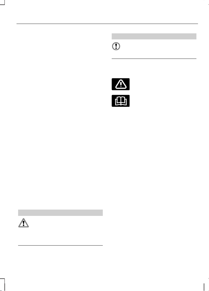
ОБ ЭТОМ РУКОВОДСТВЕ
Благодарим вас за то, что вы
остановили свой выборна автомобиле
Ford. Рекомендуем уделить время и
лучше ознакомиться с возможностями
вашего автомобиля с помощьюданного
руководства. Чем лучше вы знаете
автомобиль, тем безопаснее и
приятнее будет вождение.
Примечание: В руководстве
описываются все модели и
дополнительные аксессуары, иногда
даже до их появления в продаже. В нем
также могут упоминаться
устройства, которые не установлены
в вашем автомобиле.
Примечание: Строго соблюдайте все
действующие правила и законы при
пользовании автомобилем.
Примечание: В случае продажи
автомобиля, данное руководство
необходимо передать новому
владельцу. Оно является
неотъемлемой принадлежностью
автомобиля.
СЛОВАРЬ СИМВОЛОВ
Символы используемые в
руководстве
ПРЕДУПРЕЖДЕНИЕ
Нарушение инструкций, которые
отмечены знаком
предупреждения, может привести к
смерти или увечьям для вас или
окружающих.
ПРЕДОСТЕРЕЖЕНИЕ
Знак особого внимания отмечает
инструкции, нарушение которых
ведет к повреждению автомобиля.
Символы наносимые на узлы
автомобиля
Если вы видите один изэтих символов,
прочтите соответствующий раздел
руководства прежде, чем прикасаться
к узлу или пытаться регулировать
что-либо.
ЗАПАСНЫЕ ЧАСТИ И
АКСЕССУАРЫ
Оригинальные запасны части и
аксессуары Ford были разработаны
специально для вашего автомобиля.
За исключением отдельно указанных
случаев, компания Ford не проводила
испытания неоригинальных запасных
частей и аксессуаров. По этой причине
мы не можем гарантировать, что
данные запасные части и аксессуары
будут соответствовать конструкции
вашего автомобиля. Мы рекомендуем
вам проконсультироваться со
специалистами официального
дилерского центра Ford по поводу
установки запасных частей и
аксессуаров.
7
Введение
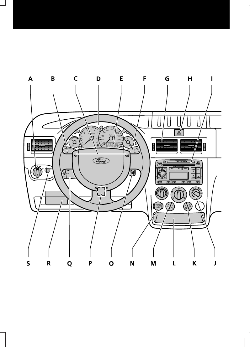
БЫСТРЫЙ ОБЗОР
Панель управления
Автомобили с левым расположением рулевого колеса
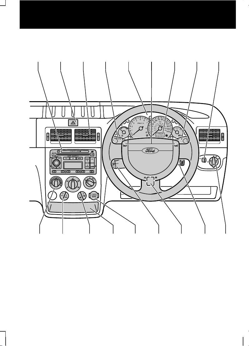
Автомобили с правым расположением рулевого колеса
E74267
I H G B D C E F S
J M K L N Q P O A
Органы управления осветительными приборами См. Осветительное
оборудование (стр. 41).
A
Указатели поворота См. Осветительное оборудование (стр. 41).B
Звуковой сигналC
Панель приборов См. Функции обеспечения комфорта (стр. 78).D
9
Быстрый обзор

Информационный дисплей См. Маршрутный компьютер (стр. 59).E
Подрулевой переключатель очистителей и омывателей стекол См.
Стеклоочистители и стеклоомыватели (стр. 39).
F
Сопла системы вентиляции См. Органы управления микроклиматом
(стр. 60).
G
Кнопка аварийной световой сигнализации См. Осветительное
оборудование (стр. 41).
H
Блок аудио- и навигационной систем См. «Руководство по
аудиоаппаратуре».
—I———
Органы управления микроклиматом. См. Органы управления
микроклиматом (стр. 60).
J
Выключатели обогрева ветрового и заднего стекол См. Органы
управления микроклиматом (стр. 60).
K
Пепельница вещевого отделения. См. Функции обеспечения комфорта
(стр. 78).
L
Переключатели рециркуляции и кондиционирования воздуха. См. Органы
управления микроклиматом (стр. 60).
M
Прикуриватель или дополнительная электрическая розетка. См. Функции
обеспечения комфорта (стр. 78).
N
Замок (выключатель) зажиганияO
Рычаг регулировки положения рулевой колонки См. Рулевое колесо
(стр. 37).
P
Органы управления аудиосистемой. См. Управление аудиосистемой
(стр. 37).
Q
Плавкие предохранители. См. Плавкие предохранители (стр. 106).R
Коррекция положения фар. См. Коррекция наклона световых пучков
фар (стр. 42).
S
10
Быстрый обзор
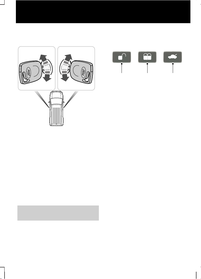
Блокировка и разблокировка
дверей с помощью ключа
РазблокироватьA
ЗаблокироватьB
Transit Connect
Что отпереть передние двери,
поверните ключ в положение A.
Что отпереть все двери, поверните
ключ в положение A дважды.
Tourneo Connect
Что отпереть передние двери,
поверните ключ в положение A.
См. Блокировка и разблокировка
замков (стр. 28).
Блокировка и разблокировка
дверей с помощью
дистанционного управления
РазблокироватьA
ЗаблокироватьB
Разблокировка замка крышки
багажника
C
Transit Connect
Чтобы отпереть только передние
двери, один раз нажмите кнопку A.
Чтобы отпереть все двери и крышку
багажника/дверь багажного отделения,
дважды нажмите кнопку A.
Чтобы отпереть крышку
багажника/дверь багажного отделения
и сдвижную дверь, один раз нажмите
кнопку C.
Tourneo Connect
Чтобы отпереть все двери и крышку
багажника/дверь багажного отделения,
один раз нажмите кнопку A.
Для всех автомобилей
Чтобы запереть все двери и крышку
багажника/дверь багажного отделения,
один раз нажмите кнопку В.
11
Быстрый обзор
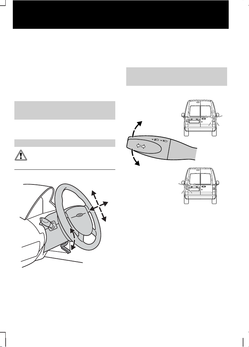
Нажмите кнопку B два раза в течение
трех секунд, чтобы активировать
двойную блокировку замков.
Примечание: Независимо от
состояния системы двойной
блокировки охранная система может
быть приведена в готовность при
повороте ключа в положение
запирания.
См. Блокировка и разблокировка
замков (стр. 28).
Регулировка положения
рулевого колеса
ПРЕДУПРЕЖДЕНИЕ
Недопустимо регулировать
положение рулевого колеса во
время движения.
Для того чтобы отрегулировать высоту
рулевого колеса и расстояние между
рулевым колесом и водителем,
освободите рычаг блокировки.
См. Регулировка положения
рулевого колеса (стр. 37).
Указатели поворота
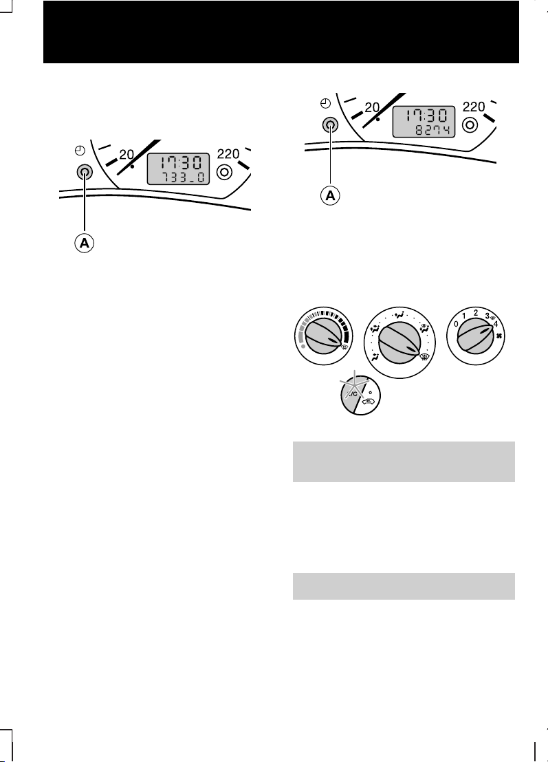
Установка часов
Вариант 1
Кнопка установки и сбросаA
• Установите переключатель
зажигания в положение II.
• Нажмите на кнопку 1 и удерживайте
ее нажатой не менее трех секунд,
пока на дисплее не начнут мигать
цифры, обозначающие время.
• Для коррекции минут нажмите
кнопку A. Для быстрой коррекции
удерживайте кнопку нажатой.
Для перехода от 12 к 24 формату или
обратно установите выключатель
зажигания в положениеI и нажмите
кнопку A.
Вариант 2
Подробная информация по настройке
часов приведена в соответствующем
руководстве по аудиосистеме
Нажмите кнопку A для отображения
времени.
Удаление инея/влаги с ветрового
стекла
См. Органы управления
микроклиматом (стр. 60).
Частота холостого хода
двигателя после пуска
После запуска непрогретого двигателя
частота холостого хода может быть
выше штатной.
См. Пуск двигателя (стр. 84).
13
Быстрый обзор
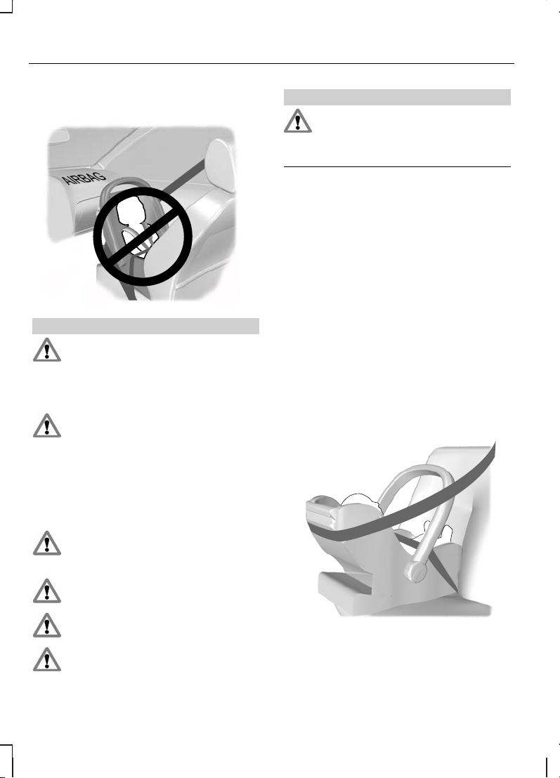
ДЕТСКИЕ СИДЕНЬЯ
ПРЕДУПРЕЖДЕНИЯ
Детей ростом меньше 150
сантиметров или младше 12 лет
следует перевозить на заднем сидении
в подходящем, одобренном к
применению детском кресле.
Оригинальный текст в
соответствии с правилом ECE
R94.01: Очень опасно! Если напротив
сиденья установлена фронтальная
подушка безопасности, не используйте
на этом сиденье устройства детской
безопасности, в которых ребенок сидит
лицом против хода движения!
При установке устройств
безопасности для детей прочтите
и выполняйте указания производителя.
Не изменяйте конструкцию таких
устройств.
Не держите ребенка на коленях
во время движения.
Не оставляйте детей в
автомобиле без присмотра.
ПРЕДУПРЕЖДЕНИЯ
Если ваш автомобиль попал в
аварию, квалифицированный
механик должен проверить состояние
устройств безопасности для детей.
Примечание: В разных странах
действуют разные требования к
применению устройств безопасности
для детей.
Удерживающие системы для детей,
утвержденные ЕСЕ и специально
проверенные и одобренныедля вашего
автомобиля, вы можете приобрести у
вашего дилера.
Устройства детской
безопасности, подходящие для
различных весовых категорий
Используйте устройства детской
безопасности следующим образом:
Детская люлька
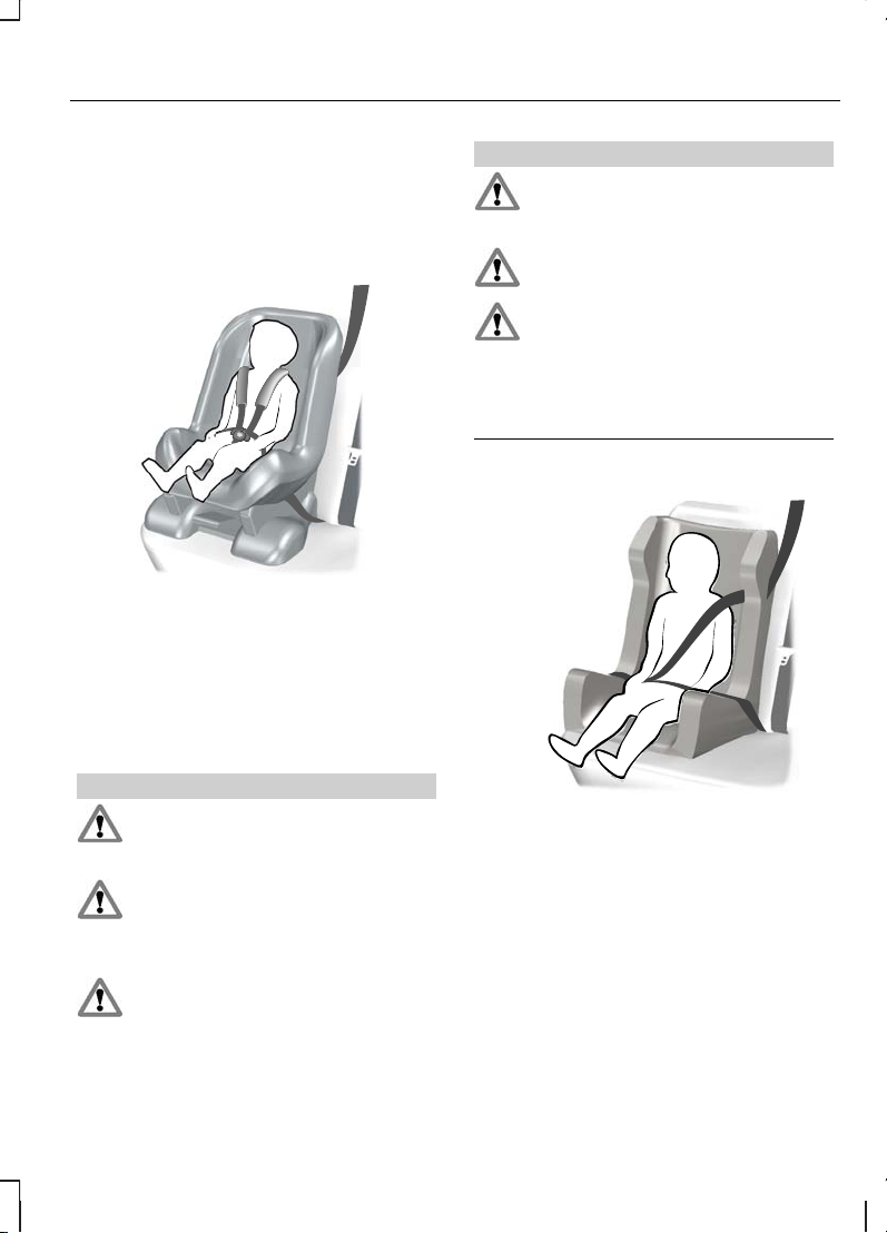
Усаживайте ребенка, который весит
менее 13 килограммов, в обращенное
назад детское кресло,
устанавливаемое на заднее сиденье.
Детское кресло
Усаживайте ребенка, который весит от
13 до 18 килограммов, в детское кресло
на заднем сиденье.
ДОПОЛНИТЕЛЬНЫЕ
ПОДУШКИ
ПРЕДУПРЕЖДЕНИЯ
Не используйте дополнительные
кресла или подушки, имеющие
лишь поясной ремень безопасности.
Не устанавливайте
дополнительное кресло или
подушку, если ремень безопасности
плохо натягивается или перекручен.
Не размещайте ремень
безопасности под рукой ребенка
или за его спиной.
ПРЕДУПРЕЖДЕНИЯ
Нельзя использовать книги,
подушки или полотенца для того,
чтобы посадить ребенка повыше.
Убедитесь, что ребенок сидит
прямо.
Помещайте ребенка, который
весит более 15 килограммов, но
ниже 150 сантиметров ростом в
дополнительное кресло или
подкладывайте дополнительную
подушку.
Дополнительное сиденье
Рекомендуется использовать
дополнительное кресло со спинкой
вместо дополнительной подушки.
Приподнятое расположение кресла
позволит разместить плечевой ремень
безопасности сидения для взрослого
человека на середине плеча ребенка,
а поясной ремень на его бедрах.
15
Безопасность детей
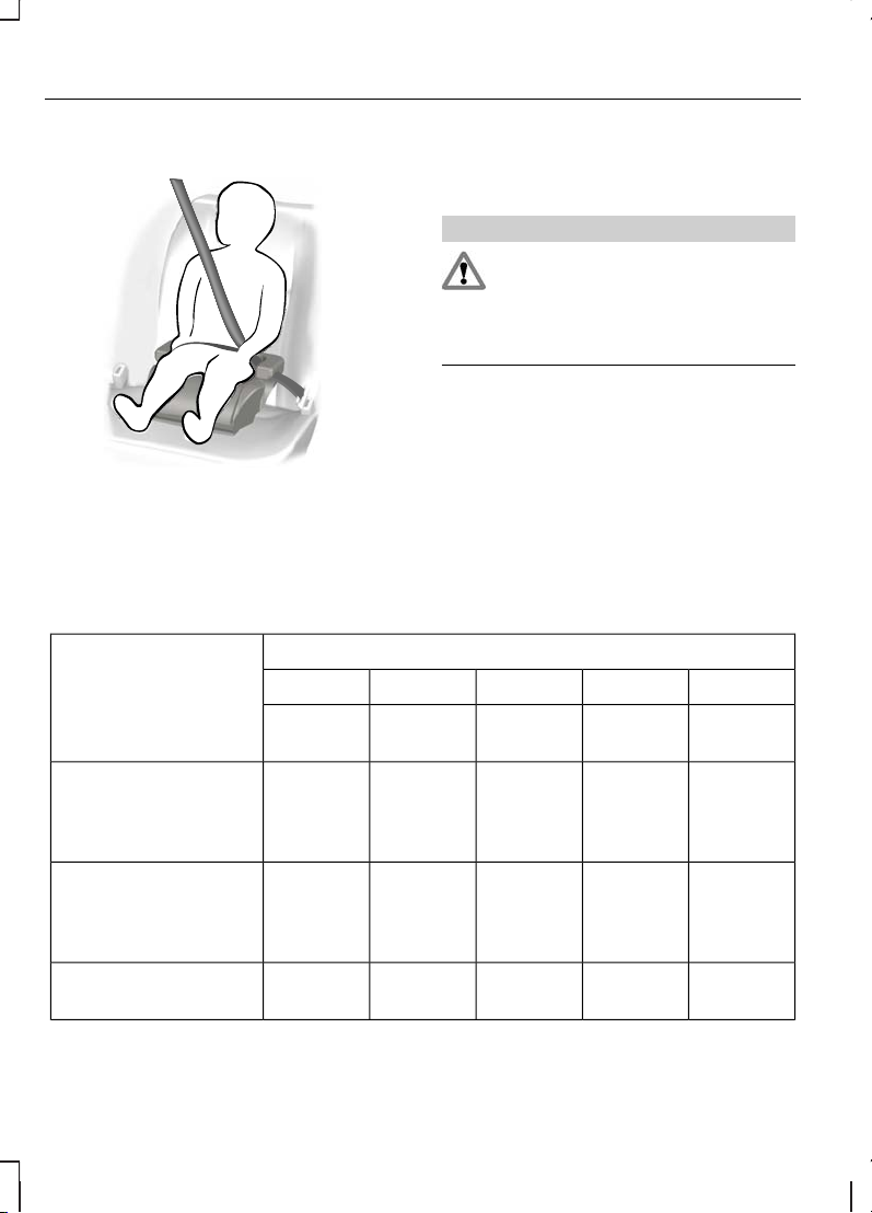
УСТАНОВКА ДЕТСКОГО
СИДЕНЬЯ
ПРЕДУПРЕЖДЕНИЕ
При использовании устройства
детской безопасности,
установленногопо ходу автомобиля на
заднем сиденье, всегда снимайте
подголовник с этого сиденья.
Примечание: Возможно, что при
установке устройства детской
безопасности на переднем сиденье,
вам будет трудно обеспечить
плотное прилегание поясной лямки
ремня безопасности. В таком случае,
установите спинку сиденья в
полностью вертикальное положение
и увеличьте высоту сиденья. См.
Передние сиденья (стр. 70).
Весовые категории (вес и возраст ребенка)
Посадочные места
IIIIII0+0
от 22 до 36
кг
от 15 до 25
кг
от 9 до 18
кг
До 13 кгДо 10 кг
U
1
U
1
U
1
XX
Переднее пассажир-
ское сиденье с
подушкой безопас-
ности перед ним
U
1
U
1
U
1
U
1
U
1
Переднее пассажир-
ское сиденье без
подушки безопас-
ности перед ним
UUUUU
Задние сиденья
второго ряда
16
Безопасность детей

Весовые категории (вес и возраст ребенка)
Посадочные места
IIIIII0+0
от 22 до 36
кг
от 15 до 25
кг
от 9 до 18
кг
До 13 кгДо 10 кг
UUUUU
Задние сиденья
третьего ряда
X Не подходит для детей данной весовой категории..
U Подходит для универсальных устройств безопасности детей данной весовой
категории.
U1Подходит для универсальных устройств безопасности для детей даннойвесовой
категории. Однако мы рекомендуем использовать одобренное устройство детской
безопасности и крепить его на заднем сиденье.
Устройства детсткой безопасности с креплениями ISOFIX
Весовые категории (вес и возраст ребенка)Посадочные места
IIIIII0+0
22 — 36 kg15 — 25 kg9 — 18 kgДо 13 кгДо 10 кг
XX
L
**
L
**
XСиденья второго ряда
с креплениямиISOFIX
XXA, B, B1,
C, D
C, D, EEКлассы креплений
ISOFIX для сидений
второго ряда*
X Не подходит для детей данной весовой категории..
L Рекомендуется только для следующих детских удерживающих устройств ISOFIX,
устанавливаемых против движения: Roemer Baby-Safe (E1-04301146), Roemer
Baby-Safe Plus (E1-04301146), Britax Cosy Tot (E1-04301146), Britax Cosy Tot
Premium (E1-04301146).
L Рекомендуется только для следующих детских удерживающих устройств ISOFIX
с верхней привязью, устанавливаемых по ходу движения (группа I): Roemer Duo
(E1-40301133).
*
Согласно ECE-R16.
N/A невозможно.
17
Безопасность детей

Примечание:**При приобретении удерживающего устройства ISOFIX уточните
его весовую категорию и типоразмер для предполагаемого места установки.
18
Безопасность детей

МЕСТА РАСПОЛОЖЕНИЯ
КРЕПЛЕНИЙ ISOFIX
Tourneo Connect
ПРЕДУПРЕЖДЕНИЯ
Ford не рекомендует
использовать систему креплений
ISOfix без одновременного применения
устройства, предотвращающего
опрокидывание детского кресла (такого
как верхняя опора или упор для ног),
установленного должным образом.
Существует риск гибели ребенка
или получения им серьезной
травмы, если инструкции изготовителя
не будут выполнены должным образом,
или в случае любого изменения
конструкции детского удерживающего
устройства.
Ваш автомобиль оборудован
креплениями ISOFIX. В случае
возникновения вопросов обратитесь к
официальному дилеру Ford.
Крепления ISOFIX содержат два
жестких выступа с защелками, которые
присоединяются к замкам на нижней
части детского кресла. Если крепления
установлены дилером Ford, на втором
ряду сидений можно увидеть две
нижние точки крепления, которые
должны быть обозначены круглой
наклейкой с надписью «ISOFIX».
Направляющие в виде конуса
позволяют легко и надежно
присоединить защелки детского
сиденья к креплениям ISOfix.
Детские сиденья с креплениями ISOfix,
не одобренные Ford,не рекомендованы
к применению компанией Ford. Ни
безопасность, ни пригодность к
использованию на вашем автомобиле
таких сидений не подтверждены
официально (независимо от того,
устанавливаются ли они при помощи
креплений ISOfix или при помощи
штатных ремней безопасности).
Крепление детского кресла
верхними лямками
ПРЕДУПРЕЖДЕНИЕ
Закрепляйте лямку только в
соответствующем креплении, как
показано на рисунке. В любом другом
случае лямка не будет выполнять своих
функций должным образом.
19
Безопасность детей
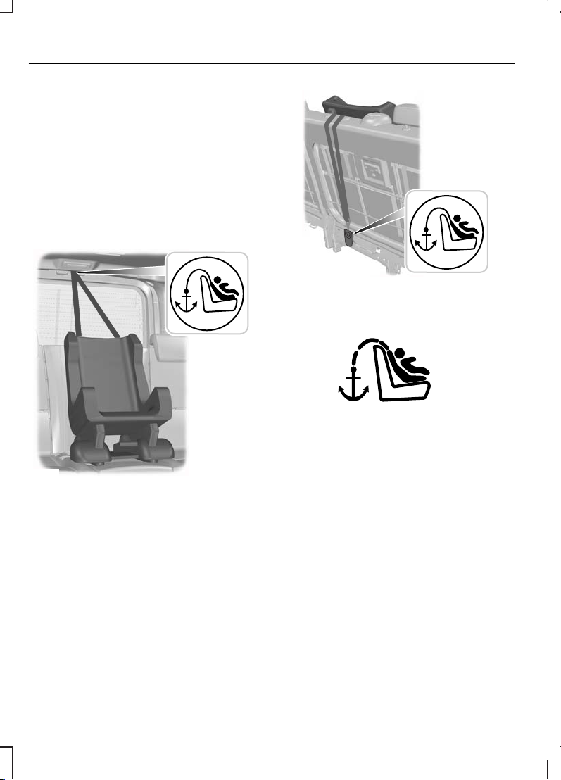
Для детских сидений, оборудованных
верхними лямками крепления,
предназначена третья точка крепления.
Она используется для фиксации
удерживающих устройств, в которых
ребенок располагается лицом по ходу
движения. Для крепления лямки
предусмотрено дополнительное
верхнее крепление. Свяжитесь с
официальным дилером Ford для
установки этого крепления.
На автомобилях с пятью местами для
сиденья этот кронштейн установлен в
проеме задней двери.
На автомобилях с восемью местами
для сиденьяон установлен за средним
сиденьем второго ряда сидений.
Кронштейн для крепления верхней
лямки удерживающих устройств
обозначен соответствующей наклейкой.
Лямку верхнего крепления следует
пропускать под приподнятым
подголовником сиденья к кронштейну.
Снимите крышку верхнего кронштейна
крепления и наденьте на него лямку.
После установки детского сиденья
затяните лямку крепления, следуя
инструкциям изготовителя.
20
Безопасность детей
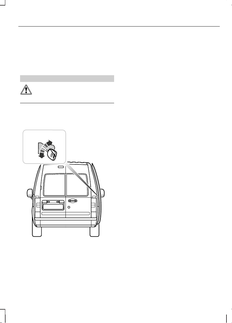
ЗАМКИ С ФУНКЦИЕЙ
БЛОКИРОВКИОТ ОТПИРАНИЯ
ДЕТЬМИ
Tourneo Connect
ПРЕДУПРЕЖДЕНИЕ
Вы не можете открыть двери
изнутри, когда используется
функция «защиты детей».
Примечание: Замки с данной
функцией установлены только на
сдвижные двери.
ЗаблокироватьA
РазблокироватьB
21
Безопасность детей
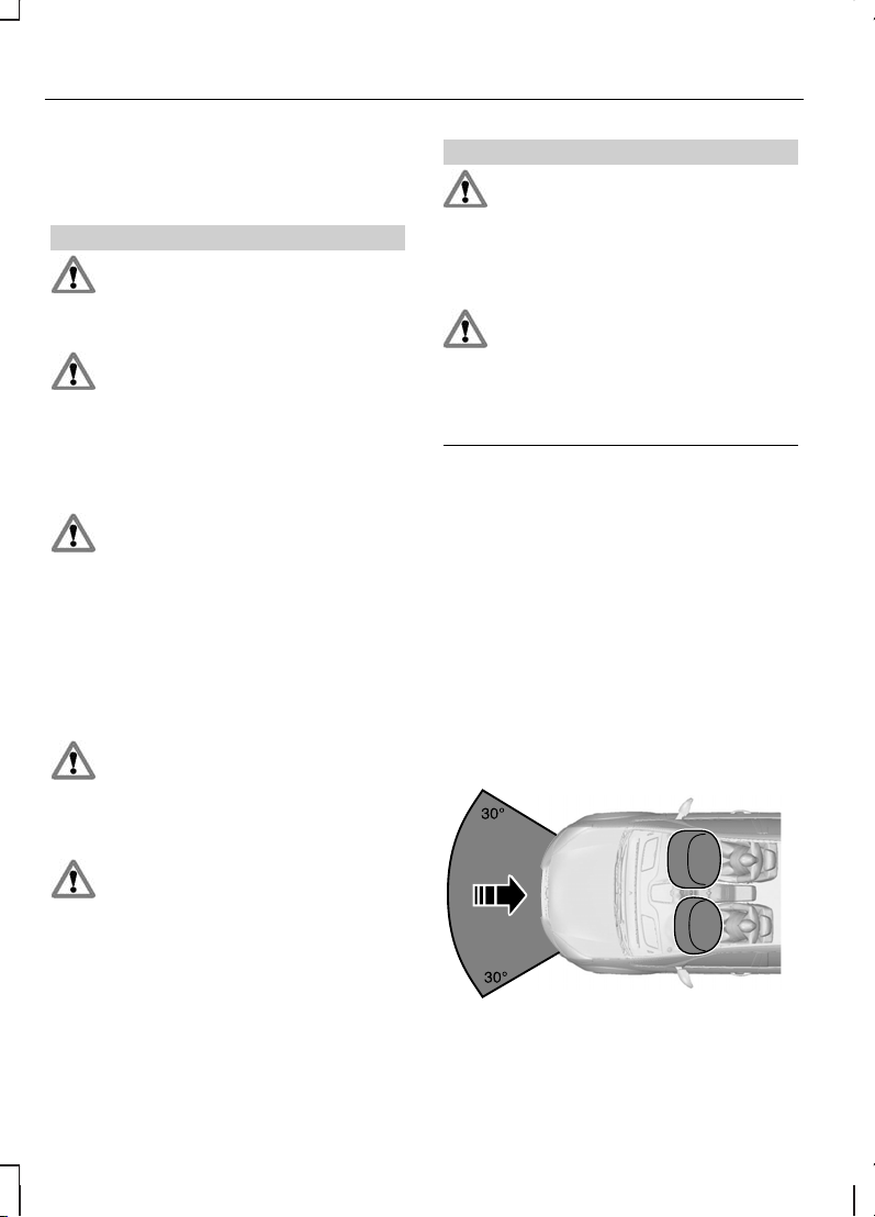
ПРИНЦИПЫ РАБОТЫ
Надувные подушки безопасности
ПРЕДУПРЕЖДЕНИЯ
Не вносите никакие изменения в
конструкцию передка автомобиля.
Это может ухудшить эффективность
срабатывания подушек безопасности.
Выдержка из ECE R94.01:
Чрезвычайно опасно! Не
используйте устройства детской
безопасности, установленные передней
частью назад на сиденьях,
защищаемых спереди подушкой
безопасности!
Пристегивайтесь ремнем
безопасности и поддерживайте
безопасное расстояние между вами и
рулевым колесом. Только правильно
пристегнутый ремень безопасности
может удержать ваше туловище в том
положении, в котором достигается
оптимальный эффект срабатывания
подушки безопасности. См. Сидение
в правильном положении (стр. 70).
Ремонт рулевого колеса, рулевой
колонки, сидений, подушек и
ремней безопасности должен
проводиться только
квалифицированным механиком.
Не закрывайте область перед
подушкой безопасности
какими-либо предметами. Не
прикрепляйте никакие предметы к
крышке подушки безопасности.
ПРЕДУПРЕЖДЕНИЯ
Не втыкайте острые предметы в
панели салона в тех зонах, где
установлены подушки безопасности.
Это может привести к повреждению и
ухудшить эффективность
срабатывания подушек безопасности.
Используйте чехлы,
предназначенные для сидений,
оборудованных боковыми подушками
безопасности. Установка чехлов
должна проводиться
квалифицированным механиком.
Примечание: При раскрытии подушки
безопасности вы услышите громкий
хлопок и увидите облако безвредного
порошка. Это нормальное явление, на
которое можно не обращать
внимания.
Примечание: Протирайте крышки
модулей подушки безопасности
только влажной тряпкой.
Фронтальные подушки безопасности
водителя и переднего пассажира
22
Защита людей, находящихся в автомобиле
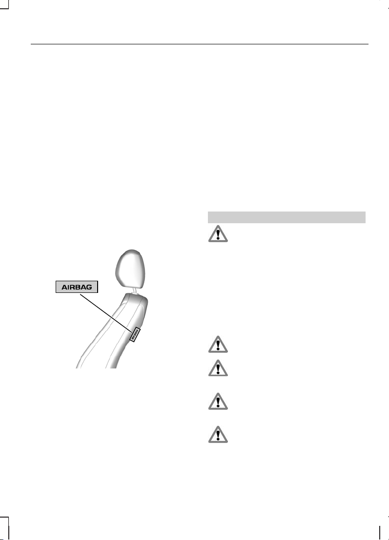
Фронтальные подушки безопасности
водителя и переднего пассажира
срабатывают при сильном лобовом
ударе или столкновении,
произошедшим под углом до 30
градусов слева или справа. Подушка
надувается за несколько тысячных
долей секунды и сдувается при
контакте с пассажирами или
водителем, амортизируя таким образом
движение тела вперед. При слабых
лобовых столкновениях,
опрокидывании, задних и боковых
столкновениях фронтальные подушки
безопасности водителя и переднего
пассажира не срабатывают.
Боковые подушки безопасности
Боковые подушки безопасности
установлены в спинках передних
сидений. О наличии боковых подушек
безопасности в автомобиле
свидетельствует табличка,
установленная в салоне.
Боковые подушки безопасности
срабатывают при сильном боковом
столкновении. Раскрывается только
подушка безопасности со стороны
столкновения. Подушки надуваются за
несколько тысячных долей секунды и
сдуваются при контакте с пассажирами
или водителем, обеспечивая таким
образом защиту области груди и плеч.
При слабых боковых столкновениях,
переворотах, фронтальных и задних
столкновениях боковые подушки
безопасности не срабатывают.
РЕМНИ БЕЗОПАСНОСТИ
ПРЕДУПРЕЖДЕНИЯ
Пристегивайтесь ремнем
безопасности и поддерживайте
безопасное расстояние между вами и
рулевым колесом. Только в том случае,
если ремень безопасности пристегнут
правильно, он способен удерживать
тело человека в положении,
обеспечивающем максимальную
эффективность действия подушки
безопасности. См. Сидение в
правильном положении (стр. 70).
Запрещается пристегивать одним
ремнем нескольких человек.
Пристегивайте ремни
безопасности к соответствующим
замкам.
Не применяйте ослабшие или
перекрученные ремни
безопасности.
Не надевайте толстую одежду.
Для достижения оптимального
эффекта ремень безопасности должен
плотно прилегать к вашему туловищу.
23
Защита людей, находящихся в автомобиле
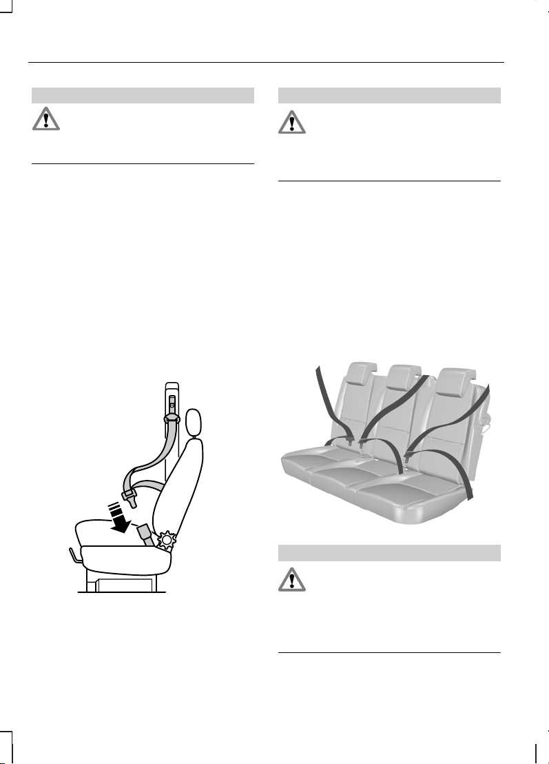
ПРЕДУПРЕЖДЕНИЯ
Наплечная лента ремня
безопасности должна пересекать
центр плеча, набедренная лента
должна плотно облегать бедра.
Механизм втягивания ремня
безопасности водителя оснащен
преднатяжителем ремня безопасности.
Преднатяжители ремней безопасности
имеют несколько более низкий порог
срабатывания, чем подушки
безопасности. При значительном
лобовом столкновении могут сработать
только преднатяжители ремней
безопасности.
ПРИСТЕГИВАНИЕ РЕМНЕЙ
БЕЗОПАСНОСТИ
ПРЕДУПРЕЖДЕНИЕ
Вставьте язычок в замок до
отчетливого щелчка. При
отсутствии щелчка ремень
безопасности не будет закреплен
должным образом.
Плавно вытяните ремень из катушки.
Если вытягивать ремень рывком или
при наклонном положении автомобиля,
его может заклинить.
Для того чтобы освободить крепление
ремня безопасности, нажмите красную
кнопку замка и дайте ремню полностью
и равномерно намотаться на катушку.
Ремни безопасности задних
сидений
ПРЕДУПРЕЖДЕНИЕ
Чтобы ремень безопасности
центрального заднего сиденья
функционировал должным образом,
необходимо, чтобы спинки задних
сидений были правильно
зафиксированы вподнятом положении.
24
Защита людей, находящихся в автомобиле
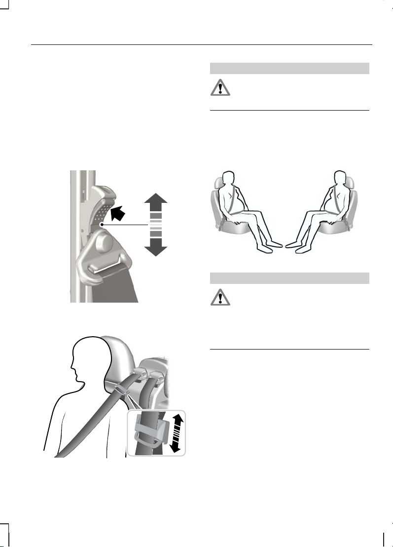
Следите за тем, чтобы каждый ремень
был закреплен в соответствующем
замке.
РЕГУЛИРОВКА ВЫСОТЫ
КРЕПЛЕНИЯ РЕМНЯ
БЕЗОПАСНОСТИ
Передний ремень безопасности
Задний ремень безопасности
ПРЕДУПРЕЖДЕНИЕ
Проследите за плавностью
протяжки ленты ремня
безопасности через направляющую.
ИСПОЛЬЗОВАНИЕ РЕМНЕЙ
БЕЗОПАСНОСТИ ВО ВРЕМЯ
БЕРЕМЕННОСТИ
ПРЕДУПРЕЖДЕНИЕ
Ради собственной безопасности
и безопасности еще не
рожденного малыша размещайте
ремень безопасности надлежащим
образом. Нельзя пользоваться только
плечевым или только пояснымремнем.
Разместите поясной ремень на бедрах
ниже живота беременной женщины.
Плечевой ремень должен проходить
между грудями выше и сбоку отживота.
25
Защита людей, находящихся в автомобиле

ОБЩАЯ ИНФОРМАЦИЯ О
РАДИОЧАСТОТАХ
ПРЕДОСТЕРЕЖЕНИЕ
Радиочастота, используемая для
дистанционной разблокировки и
блокировки замков, может также
использоваться для работы других
маломощных радиоустройств
(например, любительских
радиоприемников и передатчиков,
медицинского оборудования,
беспроводных наушников, пультов
дистанционного управления, систем
сигнализации и других приборов). Если
частота недоступна из-за помех, вы не
сможете воспользоваться пультом
дистанционного управления
блокировкой замков. Для открывания
и запирания дверей понадобится ключ.
Примечание: Двери могут
разблокироваться из-за случайного
нажатия на кнопки дистанционного
пульта.
Расстояние, на котором действует
дистанционная блокировка может
отличаться в зависимости от
окружающей обстановки.
ПРОГРАММИРОВАНИЕ
ПУЛЬТА ДИСТАНЦИОННОГО
УПРАВЛЕНИЯ
Вы можете запрограммировать для
вашего автомобиля максимум четыре
пульта дистанционного управления
(включая любые пульты, прилагаемые
к вашему автомобилю).
Примечание: Убедитесь в том, что
охранная сигнализация отключена и
все двери закрыты.
1. Переведите ключ зажигания и
положения 0 в положение II восемь
раз в течение 10 секунд. Ключ
должен остановиться в положении
II и оставаться в нем. Сработают
приводы замков, показывая этим,
что теперь возможно приступить к
программированию нового пульта
дистанционного управления.
2. Нажмите любую кнопку нового
пульта в течение 20 секунд после
срабатывания замков. Замки снова
сработают, чтобы показать, что
пульт успешно запрограммирован.
3. Повторите шаг 2 для всех пультов,
включая оригинальный. Каждый раз,
как будет успешно
запрограммирован очередной
пульт, в течение 20 секунд
действует новый период
программирования.
4. Установите ключ в замке зажигания
в положение 0. Замки снова
сработают, чтобы показать, что
пульт успешно запрограммирован.
Теперь замки автомобиля можно
отпереть и запереть только при
помощи тех пультов, которые вы
только что запрограммировали.
26
Ключи и пульты дистанционного управления
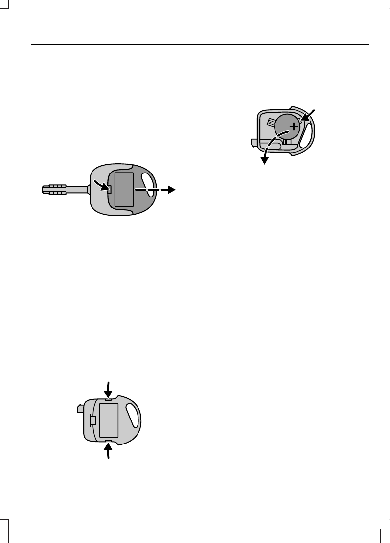
ЗАМЕНА ЭЛЕМЕНТА ПИТАНИЯ
ПУЛЬТА ДИСТАНЦИОННОГО
УПРАВЛЕНИЯ
Если радиус действия передатчика
пульта (ключа) постепенно
уменьшается, следует заменить
элемент питания (элемент питания
типа 3V CR 2032).
• Осторожно извлеките передатчик
из корпуса ключа при помощи
плоского предмета (например,
отвертки), вставив его в вырез на
тыльной стороне ключа.
• При помощи плоского инструмента
осторожно извлеките элемент
питания. Установите новый элемент
питания между контактами таким
образом, чтобы маркировка «+»
была обращена вниз. Соберите
корпус передатчика, действуя в
обратной последовательности.
• Раскройте корпус передатчика, при
помощи плоского инструмента
отсоединив крепежные зажимы,
расположенные по бокам.
• При помощи плоского инструмента
осторожно извлеките элемент
питания. Установите новый элемент
питания между контактами таким
образом, чтобы маркировка «+»
была обращена вниз. Соберите
корпус передатчика, действуя в
обратной последовательности.
27
Ключи и пульты дистанционного управления
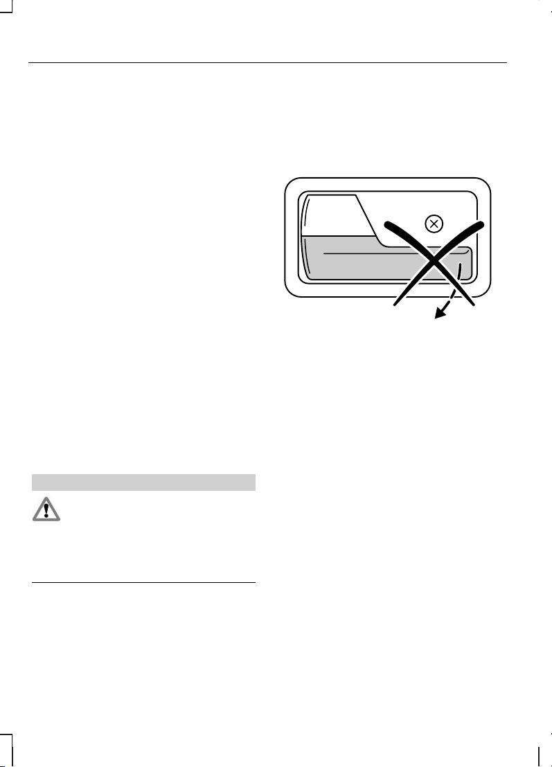
БЛОКИРОВКА И
РАЗБЛОКИРОВКА ЗАМКОВ
Система централизованной
блокировки замков
Примечание: При помощи ключа вы
можете отпереть двери и крышку
багажника/дверь багажного
отделения. Ключ может
потребоваться при отказе системы
дистанционного управления.
Примечание: При отпирании крышки
багажника/двери багажного отделения
при помощи ключа отпирается
только эта крышка/дверь.
Примечание: Централизованно
заблокировать двери можно только в
том случае, если они закрыты.
Примечание: Вы можете
деактивировать систему
централизованного запирания замков
дверей при помощи двери водителя
или переднего пассажира.
Функция двойной блокировки
ПРЕДУПРЕЖДЕНИЕ
Не задействуйте двойную
блокировку, когда люди или
животные находятся в салоне
автомобиля. После двойной
блокировки разблокировать замки
дверей со стороны салона невозможно.
Двойная блокировка — это мера
противоугонной защиты, не
позволяющая открыть двери изнутри.
Заблокировать замки дверей двойной
блокировкой можно только в том
случае, если все двери закрыты.
Подтверждение блокировки и
разблокировки замков
После разблокировки замков дверей
указатели поворота мигнут однократно.
На автомобилях, оснащенных
функцией двойной блокировки замков,
фонари указателей поворота мигнут
дважды при запирании дверей.
28
Замки
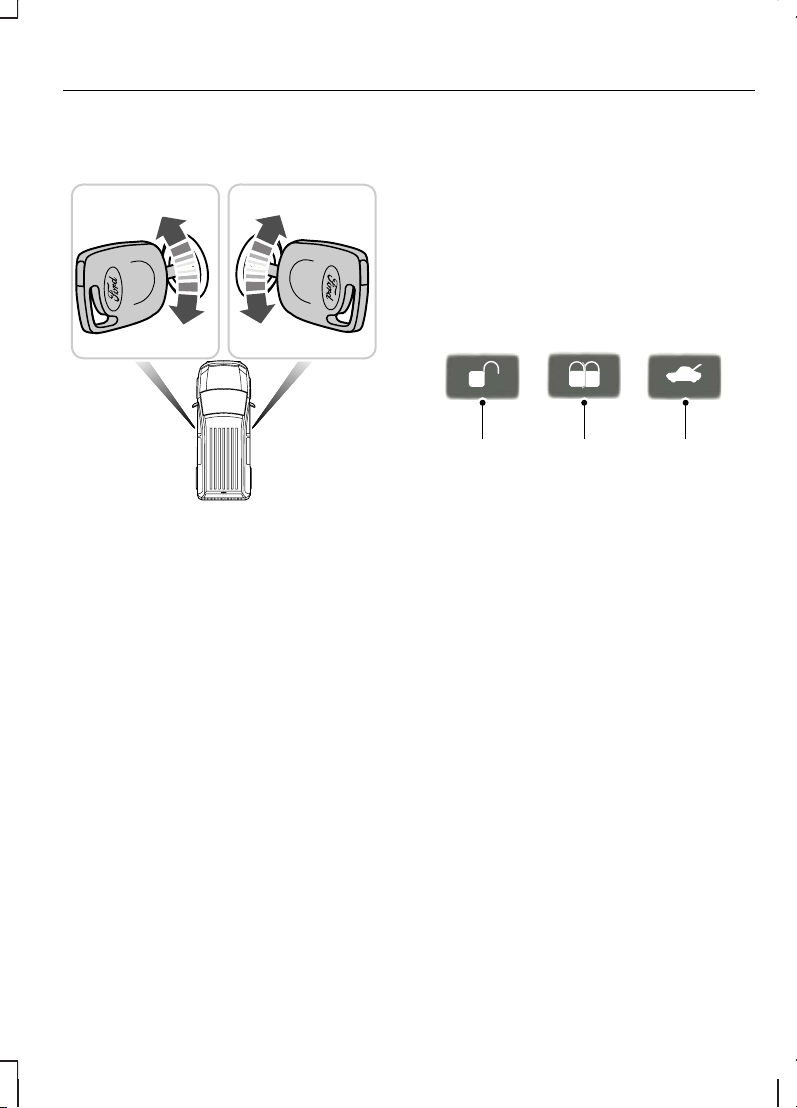
Блокировка и разблокировка
дверей с помощью ключа
РазблокироватьA
ЗаблокироватьB
Модели Tourneo Connect (с системой
дистанционного управления) и
Transit Connect
Что отпереть передние двери,
поверните ключ в положение A.
Что отпереть все двери, поверните
ключ в положение A дважды.
Модели Tourneo Connect без
системы дистанционного
управления
Для того чтобы отпереть все двери,
поверните ключ в положение A.
Двойная блокировка дверей с
помощью ключа
Для двойной блокировки замков дверей
в течение 3 секунд поверните ключ в
положение отпирания, затем – в
положение запирания.
Блокировка и разблокировка
дверей с помощью
дистанционного управления
РазблокироватьA
ЗаблокироватьB
Разблокирования крышки
багажного отделения и
сдвижных дверей
C
Чтобы отпереть только передние
двери, один раз нажмите кнопку A.
Чтобы отпереть все двери и крышку
багажника/дверь багажного отделения,
дважды нажмите кнопку A.
Чтобы отпереть крышку
багажника/дверь багажного отделения
и сдвижную дверь, один раз нажмите
кнопку C.
Чтобы запереть все двери и крышку
багажника/дверь багажного отделения,
один раз нажмите кнопку В.
Нажмите кнопку B два раза в течение
трех секунд, чтобы активировать
двойную блокировку замков.
29
Замки
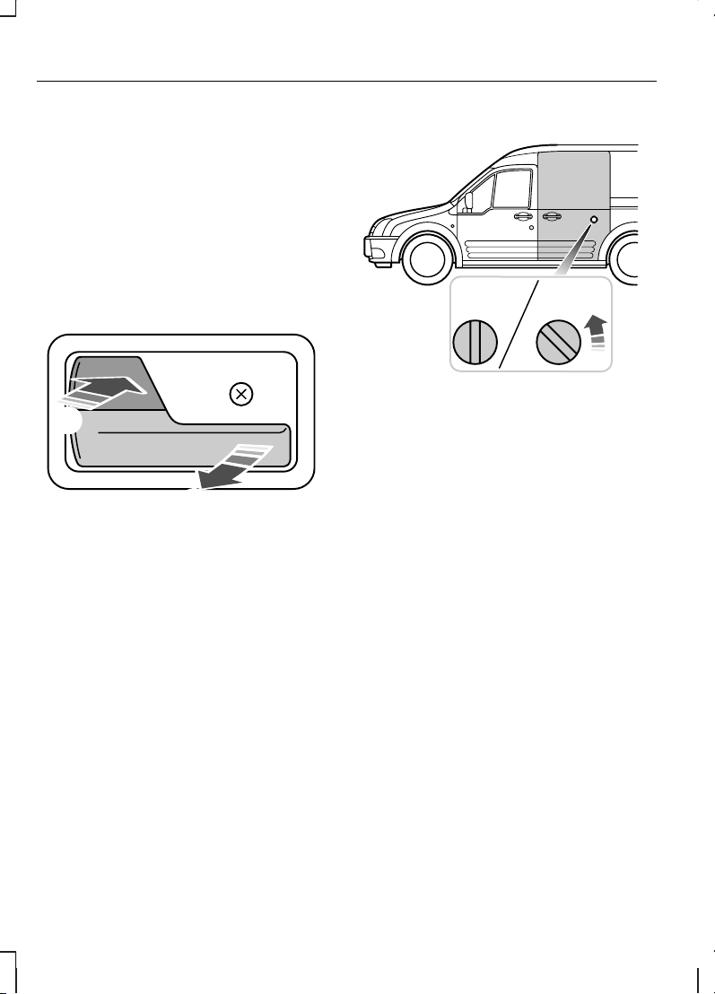
Примечание: Независимо от
состояния системы двойной
блокировки охранная система может
быть приведена в готовность при
повороте ключа в положение
запирания.
Блокировка и разблокировка
замков дверей снаружи
автомобиля
Передние двери
Блокировка замков всех
дверей
A
РазблокироватьB
Примечание: Нажатие кнопки B
позволит разблокировать замки всех
автомобиля модели Tourneo Connect
(версии без системы дистанционного
управления), или только передние
двери автомобилей модели Tourneo
Connect (версии с системой
дистанционного управления) и Transit
Connect
Сдвижная дверь
ЗаблокироватьA
РазблокироватьB
Открывание дверей
Сдвижная дверь
Примечание: На модели Tourneo
Connect движение правой сдвижной
двери ограничено при
разблокированном и открытом лючке
топливозаливной горловины.
30
Замки
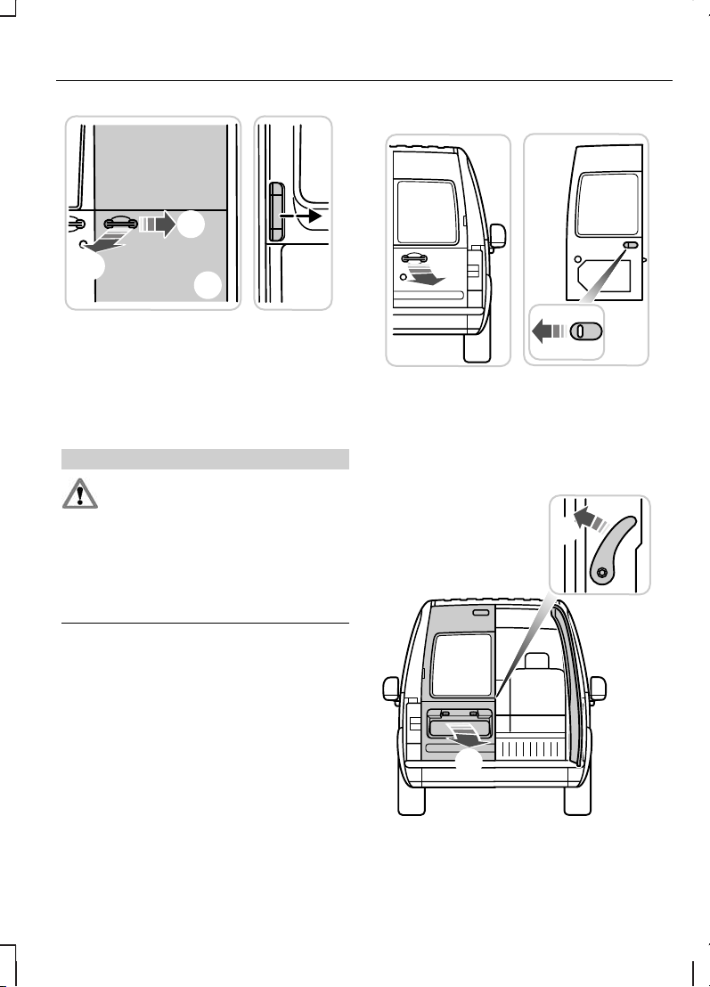
СнаружиA
ИзнутриB
Распашные задние двери
ПРЕДУПРЕЖДЕНИЕ
Правильно закрывайте заднюю
дверь багажного отделения,
чтобы исключить риск ее открывания
во время движения. Движение с
открытой задней дверью багажного
отделения очень опасно, поскольку в
салон автомобиля могут проникнуть
отработавшие газы.
Правая задняя дверь
СнаружиA
ИзнутриB
Левая задняя дверь
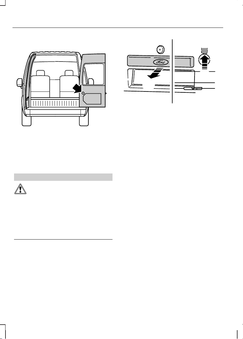
Открывание дверей на 180 и 250
градусов
Нажмите желтую кнопку на двери.
Установка ограничителей в исходное
положение происходит автоматически
при закрывании дверей.
Крышка багажного отделения
ПРЕДУПРЕЖДЕНИЕ
Закройте крышку багажника/дверь
багажного отделения должным
образом, чтобы предотвратить ее
открывание во время движения.
Движение с открытой крышкой
багажника/дверью багажного отделения
очень опасно, поскольку в салон
автомобиля могут проникнуть
отработавшие газы.
Примечание: Чтобы открыть крышку
багажника/дверь багажного отделения
изнутри, вы можете воспользоваться
кнопкой открывания, доступ к
которой можно получить через
отверстие в нижней части крышки
багажника/двери багажного
отделения.
СнаружиA
ИзнутриB
32
Замки

ПРИНЦИПЫ РАБОТЫ
Иммобилайзер двигателя — это система
противоугонной защиты, которая не
позволяет запустить двигатель
неправильно запрограммированным
ключом.
ЗАПРОГРАММИРОВАННЫЕ
КЛЮЧИ
Примечание: Если вы потеряете
ключ, остальные ключи будет
необходимо стереть из памяти и
перепрограммировать. Обратитесь
за дополнительной информацией к
обслуживающему вас дилеру. Сменные
ключи необходимо перекодировать
вместе с имеющимися ключами.
Примечание: Не допускайте
экранировки ключей металлическими
предметами. Это может нарушить
процесс распознавания ключа
приемником.
Если вы потеряли ключ, сменный ключ
можно получить у обслуживающего вас
дилера Ford.По возможности сообщите
дилеру номер ключа, указанный на
ярлыке, которым были снабжены
оригинальные ключи. Кроме этого, вы
можете получить у обслуживающего
вас дилера Ford дополнительные
ключи.
Программирование ключей
Для вашего автомобиля можно
закодировать не более восьми ключей
(включая те, которые поставляются
вместе с автомобилем). Для
кодирования ключей необходимо иметь
два ключа, закодированныхдля вашего
автомобиля ранее.
Выполните каждое из следующих
действий в течение не более пяти
секунд.
1. Вставьте первый ключ в замок
зажигания и поверните его в
положение II.
2. Снова поверните ключв положение
0 и извлеките ключ из замка
зажигания.
3. Вставьте второй ключ в замок
зажигания и поверните его в
положение II.
4. Снова поверните второй ключ в
положение 0 и извлеките ключ из
замка зажигания — режим
кодирования ключей активирован.
5. Если любой
незапрограммированный ключ
будет вставлен в замок зажигания
и повернут в положение II в течение
ближайших 10 секунд, то этот ключ
будет запрограммирован системой.
6. После того как процесс кодирования
завершен, извлеките ключ из замка
зажигания. Выждите пять секунд
для активации системы.
33
Иммобилайзер двигателя

Если программирование было
выполнено неправильно, то после
включения зажигания новым
запрограммированным ключом
замигает индикатор иммобилайзера, и
пуск двигателя станет невозможен.
Повторите процесс программирования,
выждав 20 секунд с включенным
зажиганием (ключ в положении II).
Удаление кода
Имея два закодированных ключа для
вашего автомобиля, вы можете
привести в неработоспособное
состояние все оставшиеся ключи,
например, в случае потери одного из
ключей:
Выполните каждое из следующих
действий в течение не более пяти
секунд.
Сначала выполните четыре первых
этапа процедуры, описанной в разделе
Кодирование ключей, затем
выполните следующие действия:
• Вставьте второй ключ в замок
зажигания и поверните его в
положение II.
• Извлеките ключ иззамка зажигания.
• Вставьте первый ключ в замок
зажигания, поверните его в
положение II и удерживайте ключ в
этом положении. Индикатор будет
мигать в течение пяти секунд.
• Если в течение этих пяти секунд
будет выключено зажигание,
процесс удаления кода будет
прерван, и удаление кода ключа не
будет выполнено.
• Если процедура удаления кода
выполнена до конца, всеми
остальными ключами (помимо тех
двух ключей, которые были
использованы для удаления кода),
пользоватьсяневозможно, если они
не будут запрограммированы снова.
После этого можно запрограммировать
дополнительные ключи.
АКТИВАЦИЯ
ИММОБИЛАЙЗЕРА
ДВИГАТЕЛЯ
Иммобилайзер двигателя включается
автоматически через некоторое время
после выключения зажигания.
Мигающий индикатор на щитке
приборов подтверждает работу
системы.
ОТКЛЮЧЕНИЕ
ИММОБИЛАЙЗЕРА
ДВИГАТЕЛЯ
Иммобилайзер двигателя отключается
автоматически после включения
зажигания правильно кодированным
ключом.
34
Иммобилайзер двигателя

При этом на панели приборов
примерно на три секунды включается
соответствующий индикатор. Если
индикатор остается включенным или
мигает в течение одной минуты, а
затем включаетсячерез неодинаковые
интервалы времени, то это
свидетельствует о том, что ключ не
распознан системой. Извлеките ключ
из замка зажигания и вставьте его еще
раз.
После попытки запустить двигатель
неправильно закодированным ключом
необходимо выждать примерно 20
секунд, прежде чем повторять попытку
с помощьюправильно закодированного
ключа.
Если запустить двигатель с помощью
правильно кодированного ключа не
удалось, это говорит о неисправности
системы. Иммобилайзер должен быть
незамедлительно проверен.
35
Иммобилайзер двигателя

ПРИНЦИПЫ РАБОТЫ
Сигнализация по периметру является
защитным средством от проникновения
посторонних лиц в ваш автомобиль
через двери и капот. Кроме того, она
защищает аудиосистему.
Срабатывание охранной
сигнализации
Установленная в режим охраны,
сигнализация срабатывает при любом
из следующих событий:
• Если кто-то откроет дверь салона,
багажное отделение или крышку
капота без использования
подходящего ключа или пульта
дистанционного управления.
• Если кто-то снял аудио или
навигационную систему.
При срабатывании сигнализации в
течение 30 секунд звучит звуковой
сигнал, а также включается аварийная
световая сигнализация, работающая 5
минут.
Любые дальнейшие попытки
произвести одно из описанных выше
действий приведут к повторному
срабатыванию сигнализации.
АКТИВАЦИЯ СИГНАЛИЗАЦИИ
Для включения сигнализации
заблокируйте замки автомобиля. См.
Замки (стр. 28).
ОТКЛЮЧЕНИЕ
СИГНАЛИЗАЦИИ
Отключите охранную сигнализацию,
отперев ключом либо одну из передних
дверей, либо багажное отделение.
36
Сигнализация
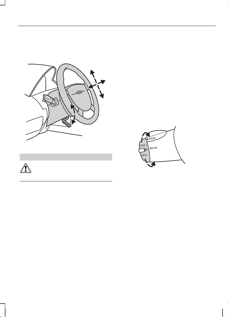
РЕГУЛИРОВКА ПОЛОЖЕНИЯ
РУЛЕВОГО КОЛЕСА
ПРЕДУПРЕЖДЕНИЕ
Недопустимо регулировать
положение рулевого колеса во
время движения.
Для того чтобы отрегулировать высоту
рулевого колеса и расстояние между
рулевым колесом и водителем,
освободите рычаг блокировки.
Верните рычаг в исходное положение,
чтобы зафиксировать рулевое колесо.
См. Сидение в правильном
положении (стр. 70).
УПРАВЛЕНИЕ
АУДИОСИСТЕМОЙ
При помощи панели управления
аудиосистемой выберите режим
работы аудиосистемы: радиоприемник,
воспроизведение CD-дисков или
компакт-кассет.
Система дистанционного управления
позволяет управлять следующими
функциями:
Регулировка громкости
Для увеличения громкости: потяните
переключатель VOL+ в сторону
рулевого колеса.
Для уменьшения громкости: Потяните
рычаг VOL−в сторону рулевого колеса.
37
Рулевое колесо
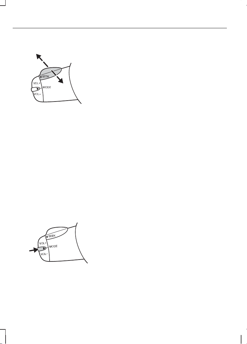
Передвиньте переключатель SEEK в
сторону рулевого колеса или панели
управления:
• В режиме радиоприемника будет
выполнен поиск ближайшей
радиостанции с меньшей или
большей частотой вещания в
данном диапазоне.
• В режиме воспроизведения
компакт-дисков произойдет
переход к последующей или
предыдущей записи на диске.
Настройка (кнопка «Mode»)
Коротко нажмите и отпустите кнопку,
расположенную сбоку.
• В режиме радиоприемника будет
выполнен поиск ближайшей
предварительно настроенной
радиостанции.
• В режиме CD произойдет выбор
следующего диска, если на
автомобиле установлен
CD-чейнджер.
• Во всех режимах будет прерван
прием транслируемой по радио
дорожной информации.
Нажмите и удерживайте кнопку,
расположенную сбоку:
• В режиме прослушивания
радиопередач для смены
диапазона вещания.
38
Рулевое колесо
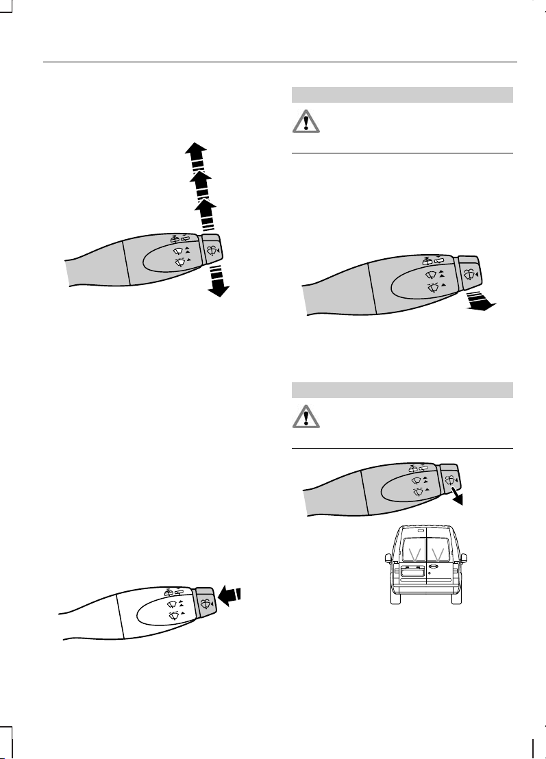
ОЧИСТИТЕЛИ ВЕТРОВОГО
СТЕКЛА
Однократная очисткаA
Очистка в прерывистом
режиме
B
Обычная очисткаC
Высокоскоростная очисткаD
ОМЫВАТЕЛИ ВЕТРОВОГО
СТЕКЛА
ПРЕДУПРЕЖДЕНИЕ
Не включайте омыватель
ветрового стекла на время более
10 секунд или при пустом бачке.
ОЧИСТИТЕЛЬ И ОМЫВАТЕЛИ
ЗАДНЕГО СТЕКЛА
Прерывистая работа
стеклоочистителей
Омыватель
ПРЕДУПРЕЖДЕНИЕ
Не включайте омывательзаднего
стекла более чем на 10 секунд,
или если бачок омывателя пустой.
39
Стеклоочистители и стеклоомыватели
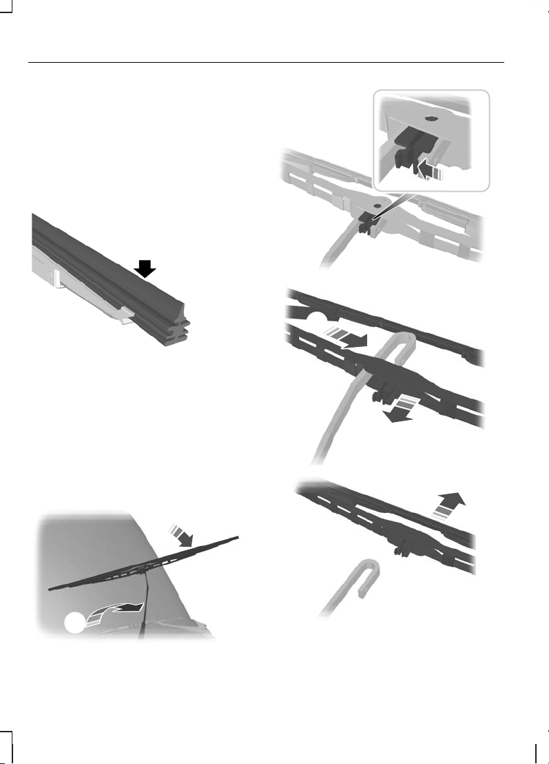
Потяните рычаг до упора по
направлению к рулевому колесу и
удерживайте рычаг, чтобы привести в
действие омыватель.
ПРОВЕРКА ЩЕТОК
СТЕКЛООЧИСТИТЕЛЕЙ
Проведите подушечками пальцев по
кромке щетки стеклоочистителя.
Очищайте рабочие кромки щеток
стеклоочистителей при помощи воды
и мягкой губки.
ЗАМЕНА ЩЕТОК
СТЕКЛООЧИСТИТЕЛЕЙ
Установка выполняется в обратной
последовательности.
40
Стеклоочистители и стеклоомыватели
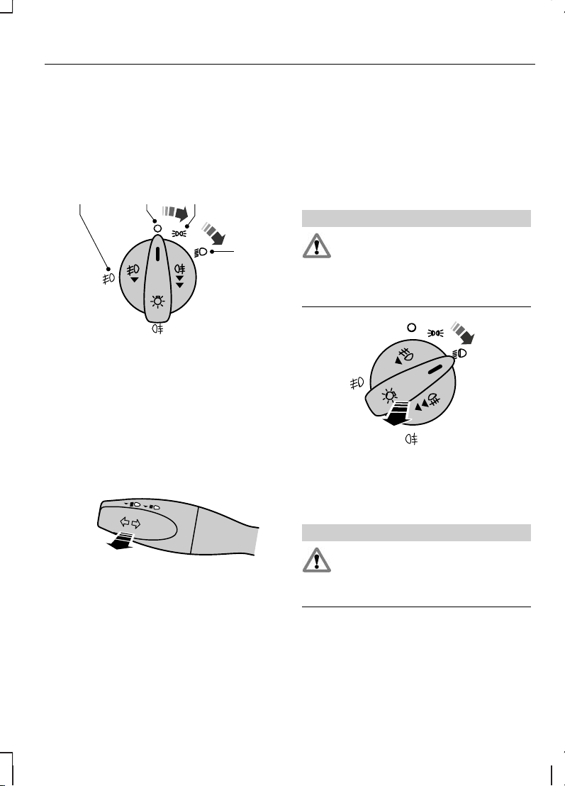
ОРГАНЫ УПРАВЛЕНИЯ
ОСВЕТИТЕЛЬНЫМ
ОБОРУДОВАНИЕМ
Переключатель приборов наружного
освещения
Выкл.A
Передние и задние
габаритные фонари
B
ФарыC
Передние противотуманные
фары
D
Дальний и ближний свет фар
Для переключения между ближним и
дальним светом фар потяните рычаг
подрулевого переключателя до упора
по направлению к рулевому колесу.
Сигнализация дальним светом фар
Слегка потяните рычаг в сторону
рулевого колеса.
ПЕРЕДНИЕ
ПРОТИВОТУМАННЫЕ ФАРЫ
ПРЕДУПРЕЖДЕНИЕ
Используйте передние
противотуманные фары, только
если видимость значительно
ограничена из-за тумана, снега или
дождя.
ЗАДНИЕ ПРОТИВОТУМАННЫЕ
ФОНАРИ
ПРЕДУПРЕЖДЕНИЕ
Включайте задние
противотуманные фонари только
в условиях ограниченной видимости
(менее 50 м).
41
Осветительное оборудование
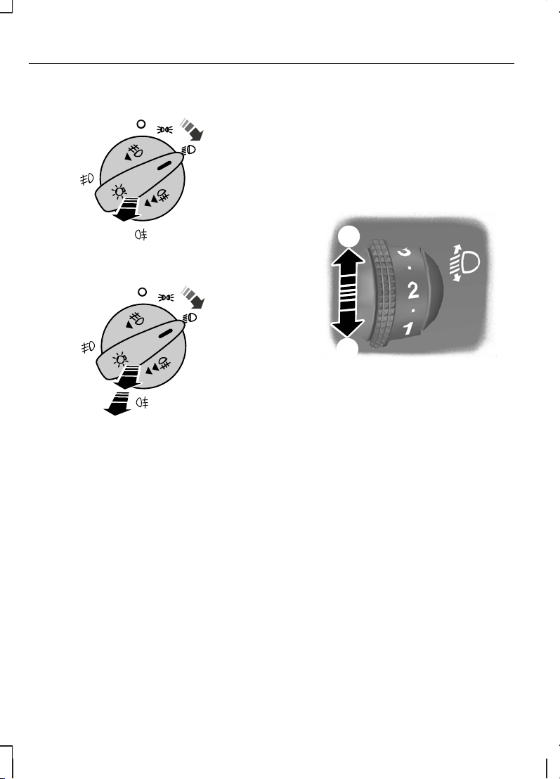
Автомобили без передних
противотуманных фар
Автомобили с передними
противотуманными фарами
КОРРЕКЦИЯ НАКЛОНА
СВЕТОВЫХ ПУЧКОВ ФАР
Все автомобили
Вы можете отрегулировать наклон
световых пучков фар в соответствии с
загрузкой автомобиля.
Увеличение наклонаA
Уменьшение наклонаB
Рекомендуемые положения
наклона световых пучков фар
Примечание: При буксировке прицепа
может потребоваться более высокое
положение пучка фар (положение «+ 1»
регулятора).
42
Осветительное оборудование

Transit Connect
Положение регулятораНагрузка
T220/T230T210T200Груз в багажном отде-
лении
1
Количество
человек
000—1
1.53/2
4
1,52
макс.
1
1
1
Если автомобиль оборудован системой регулировки уровня/высоты подъема
кузова, может потребоваться регулировка наклона световых пучков фар.
2
См. Идентификация автомобиля (стр. 140).
3
Удлиненная колесная база.
4
Короткая колесная база.
Tourneo Connect
Положение регулятораНагрузка
K230K220K200/K210Груз в багажном отде-
лении
1
Количество человек
ЗадниеПередние
000——1-2
00,50—12
00,5
02/0.5
3
—32
1.53/2.5
2
1
12/1.5
3
макс.
1
32
22/2.5
3
2,5
22/2.5
3
макс.
1
—1
1
См. Идентификация автомобиля (стр. 140).
2
Удлиненная колесная база.
3
Короткая колесная база.
43
Осветительное оборудование
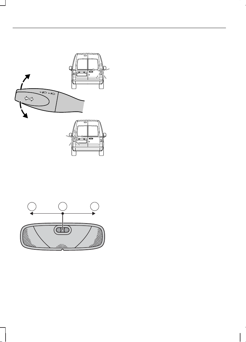
УКАЗАТЕЛИ ПОВОРОТА
ПЛАФОНЫ ВНУТРЕННЕГО
ОСВЕЩЕНИЯ
Вентилятор выключенA
Действие от контактовдверейB
ВключеноC
Если переключатель находится в
положении B, то лампа центрального
плафона освещения салона загорится
при открывании или разблокировании
замка боковой двери или двери
багажного отделения. Если при
выключенном зажигании вы оставите
дверь открытой, то, во избежание
разрядки аккумуляторной батареи,
через некоторое время центральный
плафон автоматически выключится.
Чтобы ее включить, на короткое время
включите зажигание.
Также лампа освещения салона
загорится, когда вы выключите
зажигание. Она автоматически погаснет
через некоторое время или когда вы
запустите двигатель.
Если при выключенном зажигании вы
установите переключатель в
положение C, то это приведёт к
включению центрального плафона
освещения салона. Через некоторое
время она погаснет, чтобы
предотвратить разрядку
аккумуляторной батареи. Чтобы ее
включить, на короткое время включите
зажигание.
44
Осветительное оборудование
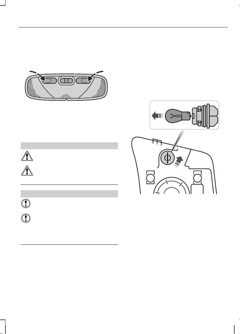
Плафоны местного освещения
(для чтения)
ЗАМЕНА ЛАМП
ПРЕДУПРЕЖДЕНИЯ
Выключите приборы освещения
и зажигание.
Перед снятием лампыподождите
некоторое время, чтобы она
остыла.
ПРЕДОСТЕРЕЖЕНИЯ
Не прикасайтесь к стеклянной
колбе лампы.
Устанавливайте только
подходящие по техническим
требованиям лампы. См. Таблица
технических характеристик ламп
(стр. 49).
Примечание: При замене лампы
протрите колбу лампы влажной
неворсистой тканью, чтобы снять
заряд статического электричества,
которое притягивает пыль к
пластмассовым рассеивателям.
Примечание: Далее приведены
инструкции, описывающие правильное
снятие ламп. Установка
производится в последовательности,
обратной снятию, если нет
дополнительных указаний.
Фара головного света
Индикатор указателей поворота
1. Поверните против часовой стрелки
и снимите патрон лампы.
2. Осторожно вдавите лампув патрон,
поверните против часовой стрелки
и извлеките лампу наружу.
45
Осветительное оборудование
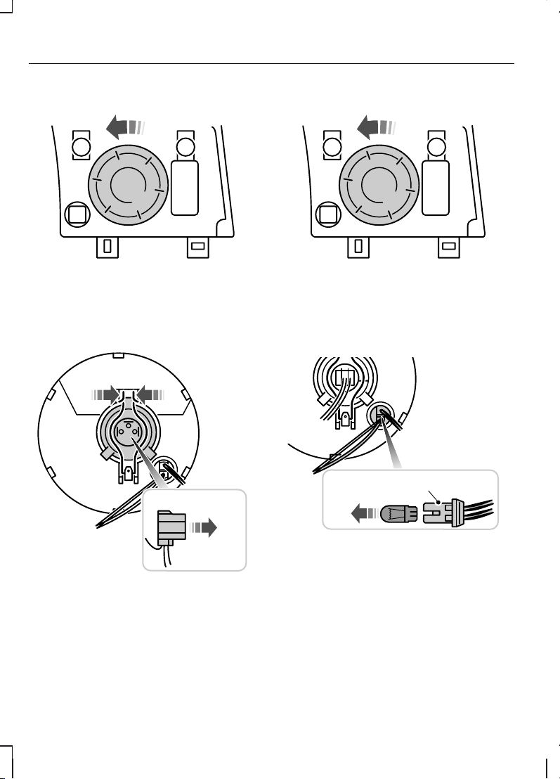
Дальний и ближний свет фар
Примечание: При установке крышки
проследите за тем, чтобы стрелка
была обращена вверх.
1. Поверните крышку против часовой
стрелки и снимите ее.
2. Отсоедините штекерный разъем.
3. Освободите зажим и снимите
лампу.
Габаритные фонари
Примечание: При установке крышки
проследите за тем, чтобы стрелка
была обращена вверх.
1. Поверните крышку против часовой
стрелки и снимите ее.
2. Снимите лампу и патрон лампы.
3. Извлеките лампу.
46
Осветительное оборудование
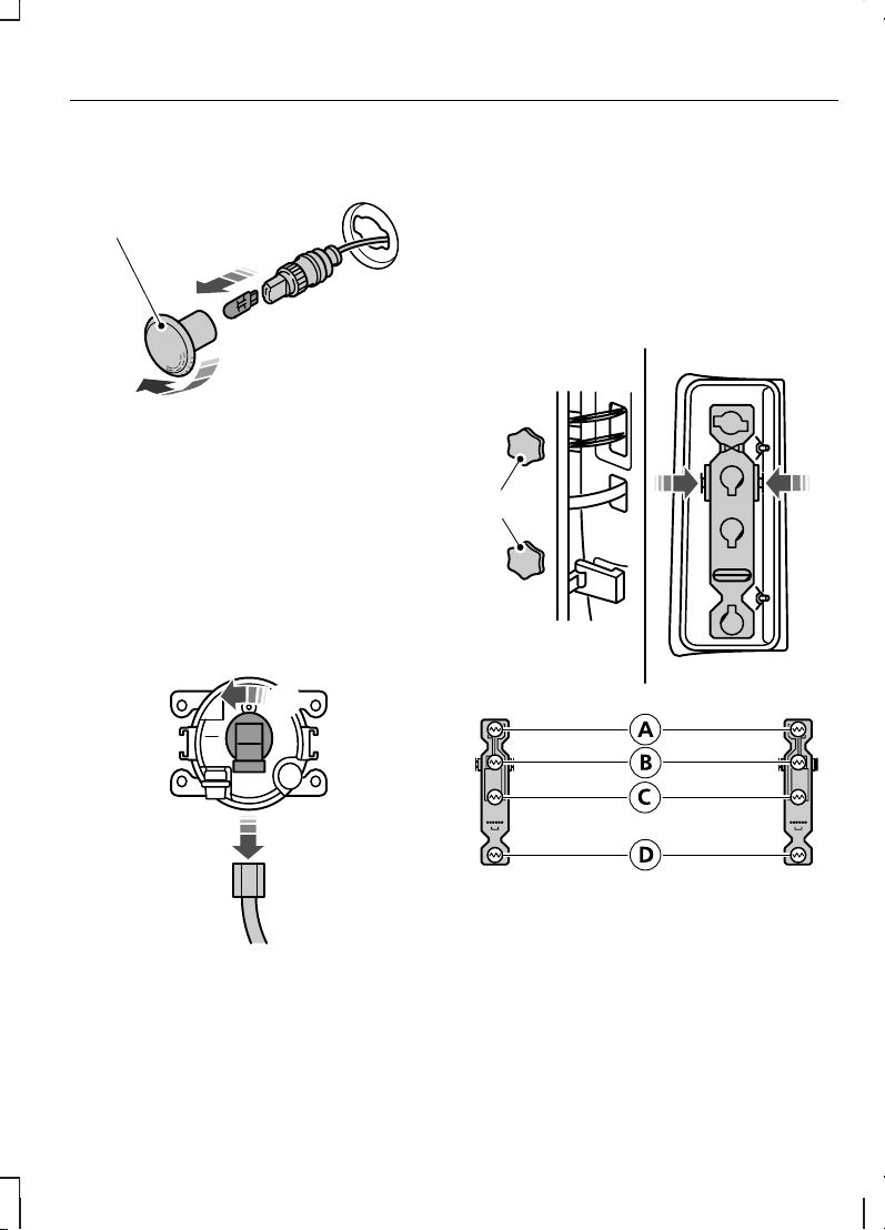
Боковые повторители
указателей поворота
1. Аккуратно снимите боковой
повторитель указателя поворота.
2. Удерживая патрон лампы,
поверните против часовой стрелки
и снимите корпус.
3. Извлеките лампу.
Передние противотуманные
фары
Примечание: Узел лампы и патрона
противотуманной фары является
неразборным.
Примечание: Доступ к лампе
возможен с тыльной стороны
переднего бампера.
1. Отсоедините штекерный разъем.
2. Поверните против часовой стрелки
и снимите патрон лампы.
Задние фонари
Задний фонарь и стоп-сигналA
Индикатор указателей
поворота
B
Фонарь заднего ходаC
Противотуманный фонарьD
47
Осветительное оборудование
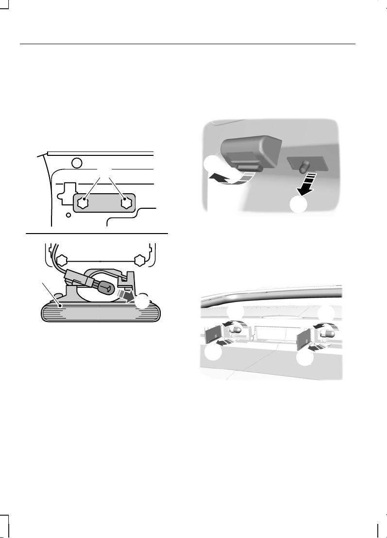
1. Выверните барашковые гайки.
2. Снимите задний фонарь и
открепите патрон лампы.
3. Осторожно вдавите лампув патрон,
поверните против часовой стрелки
и извлеките лампу наружу.
Центральный стоп-сигнал
1. Выверните винты.
2. Снимите модуль лампы.
3. Извлеките лампу.
Фонарь подсветки
регистрационного знака
Автомобилис распашными задними
дверьми
1. Снимите рассеиватель.
2. Извлеките лампу.
Автомобили с откидной задней
дверью
1. Раскройте рассеиватель.
2. Осторожно вдавите лампув патрон,
поверните против часовой стрелки
и извлеките лампу наружу.
48
Осветительное оборудование
 Loading…