- Manuals
- Brands
- Yamaha Manuals
- Motorcycle
- XJ6
- Owner’s manual
-
Contents
-
Table of Contents
-
Troubleshooting
-
Bookmarks
Quick Links
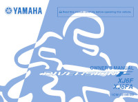
OWNER’S MANUAL
XJ6
XJ6 ABS
MOTORCYCLE
Read this manual carefully before oper-
ating this vehicle.
XJ6N
XJ6NA
B61-28199-E1
Related Manuals for Yamaha XJ6
Summary of Contents for Yamaha XJ6
-
Page 1
OWNER’S MANUAL XJ6 ABS MOTORCYCLE Read this manual carefully before oper- ating this vehicle. XJ6N XJ6NA B61-28199-E1… -
Page 2
EAU69471 Read this manual carefully before operating this vehicle. This manual should stay with this vehicle if it is sold. YAMAHA MOTOR ELECTRONICS CO., LTD. 1450-6, Mori, Mori-machi, Shuchi-gun, Shizuoka-ken, 437-0292 Japan DECLARATION of CONFORMITY Product: IMMOBILIZER Model: 5VS-00 Supplied by… -
Page 3
EAU10103 Welcome to the Yamaha world of motorcycling! As the owner of the XJ6N / XJ6NA, you are benefiting from Yamaha’s vast expe- rience and newest technology regarding the design and manufacture of high- quality products, which have earned Yamaha a reputation for dependability. -
Page 4: Important Manual Information
*Product and specifications are subject to change without notice. EAU10201 XJ6N / XJ6NA OWNER’S MANUAL ©2015 by Yamaha Motor Co., Ltd. 1st edition, August 2015 All rights reserved. Any reprinting or unauthorized use without the written permission of Yamaha Motor Co., Ltd.
-
Page 5: Table Of Contents
Table of contents Safety information ……1-1 Periodic maintenance and adjustment ……..6-1 Description ……..2-1 Owner’s tool kit……. 6-2 Left view ……….2-1 Periodic maintenance chart for the Right view……..2-2 emission control system….6-3 Controls and instruments….2-3 General maintenance and lubrication chart……6-4 Instrument and control functions..3-1 Removing and installing the Immobilizer system ……3-1…
-
Page 6
Table of contents Battery ………. 6-33 Replacing the fuses…… 6-34 Replacing the headlight bulb..6-36 Replacing the auxiliary light bulb ……….. 6-38 Replacing the brake/tail light bulb ……….. 6-39 Replacing a turn signal light bulb ……….. 6-39 Replacing the license plate light bulb ……….. -
Page 7: Safety Information
Safety information EAU1028B an accident or equipment damage. See page 4-1 for a list of pre-operation checks. Be a Responsible Owner This motorcycle is designed to As the vehicle’s owner, you are re- carry the operator and a passen- sponsible for the safe and proper oper- ger.
-
Page 8
Safety information Many accidents involve inexperi- • The passenger should always enced operators. In fact, many op- hold onto the operator, the seat erators who have been involved in strap or grab bar, if equipped, accidents do not even have a cur- with both hands and keep both rent motorcycle license. -
Page 9
Safety information Avoid Carbon Monoxide Poisoning extra care when riding a motorcycle All engine exhaust contains carbon that has added cargo or accessories. monoxide, a deadly gas. Breathing Here, along with the information about carbon monoxide can cause head- accessories below, are some general aches, dizziness, drowsiness, nausea, guidelines to follow if loading cargo to confusion, and eventually death. -
Page 10
Genuine does not in any way reduce Yamaha accessories, which are avail- ground clearance or cornering able only from a Yamaha dealer, have clearance, limit suspension travel, been designed, tested, and approved steering travel or control opera- by Yamaha for use on your vehicle. -
Page 11: Specifications
Safety information operator and may limit control torcycle, such as the frame or up- ability, therefore, such accesso- per front fork triple clamp (and not, ries are not recommended. for example, to rubber-mounted Use caution when adding electri- handlebars or turn signals, or cal accessories.
-
Page 12: Description
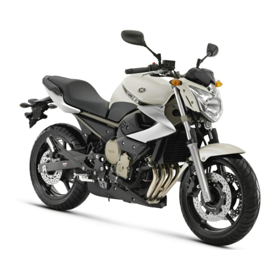
Description EAU63371 Left view 1. Air filter element (page 6-16) 2. Idle adjusting screw (page 6-17) 3. Seat lock (page 3-18) 4. Fuses (page 6-34) 5. Owner’s tool kit (page 6-2) 6. Storage compartment (page 3-20) 7. Shift pedal (page 3-12) 8.
-
Page 13: Right View
Description EAU63391 Right view 1. Helmet holder (page 3-19) 2. Battery (page 6-33) 3. Rear brake fluid reservoir (page 6-25) 4. Engine oil filler cap (page 6-9) 5. Fuel tank cap (page 3-15) 6. Radiator cap (page 6-12) 7. Coolant reservoir (page 6-12) 8.
-
Page 14: Controls And Instruments
Description EAU63401 Controls and instruments 1. Clutch lever (page 3-12) 2. Left handlebar switches (page 3-10) 3. Main switch/steering lock (page 3-2) 4. Multi-function meter unit (page 3-6) 5. Front brake fluid reservoir (page 6-25) 6. Right handlebar switches (page 3-10) 7.
-
Page 15: Instrument And Control Functions
Do not grind any key or alter its cess, take the vehicle along with all shape. three keys to a Yamaha dealer to have Do not disassemble the plastic them re-registered. Do not use the key part of any key.
-
Page 16: Main Switch/Steering Lock
Instrument and control functions Keep the standard keys as well EAU10474 Main switch/steering lock as keys of other immobilizer systems away from this vehi- cle’s code re-registering key. Keep other immobilizer system keys away from the main switch as they may cause signal inter- ference.
-
Page 17
Instrument and control functions To unlock the steering EWA10062 WARNING Never turn the key to “OFF” or “LOCK” while the vehicle is moving. Otherwise the electrical systems will be switched off, which may result in loss of control or an accident. EAU10687 LOCK The steering is locked and all electrical… -
Page 18: Indicator Lights And Warning Lights
“ON”, or if the warning light remains on after confirming that the oil level is correct (see page 6-9), have a Yamaha dealer check the vehicle. 1. Turn signal indicator light “ ”…
-
Page 19
” The ABS may not work correctly. If any This warning light comes on or flashes of the above occurs, have a Yamaha if a problem is detected in the electrical dealer check the system as soon as circuit monitoring the engine. If this oc- possible. -
Page 20: Multi-Function Meter Unit
“ON”, making any setting changes to the or if the indicator light remains on, have multi-function meter unit. Changing a Yamaha dealer check the electrical settings while riding can distract the circuit. operator and increase the risk of an The self-diagnosis device also detects accident.
-
Page 21
Instrument and control functions Clock The key must be turned to “ON” before you can use the “SELECT” and “RESET” buttons. For the UK: To switch the speed- ometer and odometer/tripmeter displays between kilometers and miles, press the “SELECT” button for one second. -
Page 22
“ ” 0.70 Imp.gal), the left segment of the will flash repeatedly. If this occurs, fuel meter will start flashing, and the have a Yamaha dealer check the elec- odometer display will automatically trical circuit. change to the fuel reserve tripmeter mode “F-TRIP”… -
Page 23
Yamaha dealer check the vehicle. goes down. If the temperature does The self-diagnosis device also detects not go down, stop the engine. (See problems in the immobilizer system page 6-46.) -
Page 24: Handlebar Switches
” key and both standard keys to a 4. Horn switch “ ” 5. Hazard switch “ ” Yamaha dealer and have the stan- dard keys re-registered. Right ECA11591 NOTICE If the display indicates an error co- de, the vehicle should be checked as soon as possible in order to avoid engine damage.
-
Page 25
Instrument and control functions The hazard lights are used in case of an EAU12461 Turn signal switch “ ” emergency or to warn other drivers To signal a right-hand turn, push this when your vehicle is stopped where it switch to “ ”. -
Page 26: Clutch Lever
Instrument and control functions EAU12822 EAU12872 Clutch lever Shift pedal 1. Clutch lever 1. Shift pedal The clutch lever is located on the left The shift pedal is located on the left side of the handlebar. To disengage side of the motorcycle and is used in the clutch, pull the lever toward the combination with the clutch lever when handlebar grip.
-
Page 27: Brake Lever
Instrument and control functions EAU26825 EAU12944 Brake lever Brake pedal The brake lever is located on the right side of the handlebar. To apply the front brake, pull the lever toward the throttle grip. 1. Brake pedal The brake pedal is located on the right side of the motorcycle.
-
Page 28: Abs (For Abs Models)
This ABS has a test mode which EAU51802 ABS (for ABS models) allows the owner to experience The Yamaha ABS (Anti-lock Brake the pulsation at the brake lever or System) features a dual electronic con- brake pedal when the ABS is op- trol system, which acts on the front and erating.
-
Page 29: Fuel Tank Cap
Instrument and control functions EAU13075 EAU13222 Fuel tank cap Fuel Make sure there is sufficient gasoline in the tank. EWA10882 WARNING Gasoline and gasoline vapors are extremely flammable. To avoid fires and explosions and to reduce the risk of injury when refueling, follow these instructions.
-
Page 30
Your Yamaha engine has been de- signed to use regular unleaded gaso- line with a research octane number of 3-16… -
Page 31: Fuel Tank Breather Hose And Overflow Hose
Instrument and control functions EAU55512 EAU13434 Fuel tank breather hose and Catalytic converter overflow hose This model is equipped with a catalytic converter in the exhaust system. EWA10863 WARNING The exhaust system is hot after op- eration. To prevent a fire hazard or burns: …
-
Page 32: Seat
Instrument and control functions EAU32981 Seat Make sure that the seat is properly se- cured before riding. To remove the seat 1. Insert the key into the seat lock, and then turn it counterclockwise. 1. Seat lock 2. Unlock. 2. While holding the key in that posi- tion, lift the rear of the seat up, and then pull the seat off.
-
Page 33: Helmet Holder
Instrument and control functions 3. Place the helmet on the right side EAU46752 Helmet holder of the vehicle, and then install the seat. WARNING! Never ride with a helmet attached to the helmet holder, since the helmet may hit objects, causing loss of control and possibly an accident.
-
Page 34: Storage Compartment
Storage compartment Handlebar position The handlebar can be adjusted to one of two positions to suit the rider’s pref- erence. Have a Yamaha dealer adjust the position of the handlebar. 1. Storage compartment The storage compartment is located under the seat. (See page 3-18.) When storing the Owner’s Manual or…
-
Page 35: Adjusting The Shock Absorber Assembly
Do not dispose of a damaged or worn-out shock absorber as- sembly yourself. Take the shock absorber assembly to a Yamaha dealer for any service. 1. Extension bar 2. Special wrench 3. Spring preload adjusting ring 4.
-
Page 36: Sidestand
Therefore, check this system regularly and have a Yamaha dealer repair it if it does not function properly. 3-22…
-
Page 37
Does the engine start? The neutral switch may not be working correctly. The motorcycle should not be ridden until checked by a Yamaha dealer. With the engine still running: 6. Move the sidestand up. 7. Keep the clutch lever pulled. -
Page 38: For Your Safety — Pre-Operation Checks
Do not operate the vehicle if you find any problem. If a problem cannot be corrected by the procedures provided in this manual, have the vehicle inspected by a Yamaha dealer. Before using this vehicle, check the following points:…
-
Page 39
• Tighten if necessary. Instruments, lights, • Check operation. — signals and switches • Correct if necessary. • Check operation of ignition circuit cut-off system. Sidestand switch • If system is not working correctly, have Yamaha dealer 3-22 check vehicle. -
Page 40: Operation And Important Riding Points
This model is equipped with: there is a control or function you do not a lean angle sensor to stop the en- understand, ask your Yamaha dealer. gine in case of a turnover. In this EWA10272 case, the display will indicate error…
-
Page 41: Starting The Engine
The neutral indi- the clutch lever pulled and the cator light should come on. If not, sidestand up. ask a Yamaha dealer to check the See page 3-22 for more informa- electrical circuit. tion. 3. Start the engine by pushing the 1.
-
Page 42: Shifting
Operation and important riding points EAU16673 and drive train, which are not Shifting designed withstand shock of forced shifting. 1. Shift pedal 2. Neutral position Shifting gears lets you control the amount of engine power available for starting off, accelerating, climbing hills, etc.
-
Page 43: Tips For Reducing Fuel Consumption
The vehicle can now be operated nor- mally. ECA10311 NOTICE Keep the engine speed out of the tachometer red zone. If any engine trouble should oc- cur during the engine break-in period, immediately have a Yamaha dealer check the vehi- cle.
-
Page 44: Parking
Operation and important riding points EAU17214 Parking When parking, stop the engine, and then remove the key from the main switch. EWA10312 WARNING Since the engine and exhaust system can become very hot, park in a place where pedestri- ans or children are not likely to touch them and be burned.
-
Page 45: Periodic Maintenance And Adjustment
If you are not familiar with vehicle ser- vice, have a Yamaha dealer perform service. EWA15123 WARNING Turn off the engine when performing…
-
Page 46: Owner’s Tool Kit
If you do not have the tools or experi- ence required for a particular job, have a Yamaha dealer perform it for you.
-
Page 47: Periodic Maintenance Chart For The Emission Control System
From 50000 km (30000 mi), repeat the maintenance intervals starting from 10000 km (6000 mi). Items marked with an asterisk should be performed by a Yamaha dealer as they require special tools, data and technical skills. EAU63321…
-
Page 48: General Maintenance And Lubrication Chart
Periodic maintenance and adjustment EAU64031 General maintenance and lubrication chart ODOMETER CHECK OR READINGS MAINTENANCE JOB ITEM X 1000 km X 1000 mi √ Air filter element • Replace. • Check operation. √ √ √ √ √ Clutch • Adjust. •…
-
Page 49
Periodic maintenance and adjustment ODOMETER CHECK OR READINGS MAINTENANCE JOB ITEM X 1000 km X 1000 mi • Make sure that all nuts, bolts √ √ √ √ √ 13 * Chassis fasteners and screws are properly tight- ened. Brake lever pivot √… -
Page 50
Periodic maintenance and adjustment ODOMETER CHECK OR READINGS MAINTENANCE JOB ITEM X 1000 km X 1000 mi Lights, signals and • Check operation. √ √ √ √ √ √ 28 * • Adjust headlight beam. switches EAU18681 Air filter •… -
Page 51: Removing And Installing The Cowling And Panels
Periodic maintenance and adjustment To install the cowling EAU18724 Removing and installing the Place the cowling in the original posi- cowling and panels tion, and then install the bolts. The cowling and panels shown need to be removed to perform some of the EAU56070 maintenance jobs described in this chapter.
-
Page 52: Checking The Spark Plugs
The spark plugs are important engine components, which should checked periodically, preferably by a Yamaha dealer. Since heat and depos- its will cause any spark plug to slowly erode, they should be removed and checked in accordance with the peri- odic maintenance and lubrication 1.
-
Page 53: Engine Oil And Oil Filter Cartridge
Periodic maintenance and adjustment EAU46723 Engine oil and oil filter car- tridge The engine oil level should be checked before each ride. In addition, the oil must be changed and the oil filter car- tridge replaced at the intervals speci- fied in the periodic maintenance and lubrication chart.
-
Page 54
An oil filter wrench is available at a gasket to drain the oil from the Yamaha dealer. crankcase. 6. Apply a thin coat of clean engine oil to the O-ring of the new oil filter cartridge. -
Page 55
Periodic maintenance and adjustment 9. Refill with the specified amount of the recommended engine oil, and then install and tighten the oil filler cap. Recommended engine oil: See page 8-1. Oil quantity: Oil change: 2.50 L (2.64 US qt, 2.20 Imp.qt) With oil filter removal: 1. -
Page 56: Coolant
Yamaha dealer check and lubrication chart. the vehicle. 11. Turn the engine off, wait a few mi-…
-
Page 57
[EWA10382] be protected against frost and corrosion. If water has been added to the coolant, have a Yamaha dealer check the anti- freeze content of the coolant as soon as possible, otherwise the effectiveness of the coolant will be reduced. -
Page 58
Periodic maintenance and adjustment 1. Radiator cap 1. Bolt 2. Radiator cap retaining bolt 2. Coolant reservoir cover 3. Radiator cap retainer 3. Coolant reservoir 5. Remove the coolant reservoir 7. Drain the coolant from the coolant breather hose from the guide, and reservoir by turning it upside then remove the coolant reservoir down. -
Page 59
14. Install the coolant reservoir cap. the vehicle for coolant leakage. If 15. Start the engine, let it idle for sev- coolant is leaking, have a Yamaha eral minutes, and then turn it off. dealer check the cooling system. 16. Remove the radiator cap to check 20. -
Page 60: Replacing The Air Filter Element
If any hose is damaged, have a Yamaha dealer replace the hose before 1. Air filter case cover 2. Screw 4. Pull the air filter element out.
-
Page 61: Adjusting The Engine Idling Speed
1. Original position (paint mark) 8. Install the fuel tank bolts. 9. Install the seat. 1. Idle adjusting screw Engine idling speed: 1250–1350 r/min If the specified idling speed cannot be obtained as described above, have a Yamaha dealer make the adjustment. 6-17…
-
Page 62: Checking The Throttle Grip Free Play
Measure the throttle grip free play as and/or engine noise. To prevent this shown. from occurring, the valve clearance must be adjusted by a Yamaha dealer at the intervals specified in the periodic maintenance and lubrication chart. 1. Throttle grip free play Throttle grip free play: 3.0–5.0 mm (0.12–0.20 in)
-
Page 63: Tires
The tires must be checked before each ride. If the center tread depth reaches the specified limit, if the tire has a nail or glass fragments in it, or if the side- wall is cracked, have a Yamaha dealer replace the tire immediately. 6-19…
-
Page 64
EWA10472 their suitability for further use. WARNING EWA10902 Have a Yamaha dealer replace WARNING excessively worn tires. Besides The front and rear tires should being illegal, operating the vehi- be of the same make and de-… -
Page 65: Cast Wheels
160/60 ZR17M/C (69W) ride. If any damage is found, have Manufacturer/model: BRIDGESTONE/BT021R a Yamaha dealer replace the DUNLOP/SPORTMAX- wheel. Do not attempt even the ROADSMART smallest repair to the wheel. A de- FRONT and REAR:…
-
Page 66: Adjusting The Clutch Lever Free Play
Periodic maintenance and adjustment EAU46731 Adjusting the clutch lever free play 1. Locknut 2. Clutch lever free play adjusting nut 4. Tighten the locknut. 1. Clutch lever free play adjusting bolt 2. Clutch lever free play The clutch lever free play should mea- sure 10.0–15.0 mm (0.39–0.59 in) as shown.
-
Page 67: Checking The Brake Lever Free Play
2. Rear brake light switch adjusting nut brake lever end. If there is free play, The brake light, which is activated by have a Yamaha dealer inspect the the brake pedal and brake lever, brake system. should come on just before braking…
-
Page 68: Checking The Front And Rear Brake Pads
1. Brake pad wear indicator groove indicator groove almost appears, have Each front brake pad is provided with a a Yamaha dealer replace the brake wear indicator groove, which allows pads as a set. you to check the brake pad wear with- out having to disassemble the brake.
-
Page 69: Checking The Brake Fluid Level
Specified brake fluid: brake system for leakage. If the brake DOT 4 fluid level goes down suddenly, have a Yamaha dealer check the cause before EWA16011 further riding. WARNING Improper maintenance can result in loss of braking ability.
-
Page 70: Changing The Brake Fluid
Periodic maintenance and adjustment EAU22733 EAU22762 Changing the brake fluid Drive chain slack Have a Yamaha dealer change the The drive chain slack should be brake fluid at the intervals specified in checked before each ride and adjusted the periodic maintenance and lubrica- if necessary.
-
Page 71
Periodic maintenance and adjustment 2. To tighten the drive chain, turn the drive chain slack adjusting nut at each end of the swingarm in direc- tion (a). To loosen the drive chain, turn the adjusting nut at each end of the swingarm in direction (b), and then push the rear wheel for- ward. -
Page 72: Cleaning And Lubricating The Drive Chain
If a cable is wet areas. Service the drive chain as damaged or does not move smoothly, follows. have a Yamaha dealer check or re- place it. WARNING! Damage to the ECA10584 NOTICE outer housing of cables may result…
-
Page 73: Checking And Lubricating The Throttle Grip And Cable
In pedals should be checked before each addition, the cable should be lubricat- ride, and the pedal pivots should be lu- ed by a Yamaha dealer at the intervals bricated if necessary. specified in the periodic maintenance Brake pedal chart.
-
Page 74: Checking And Lubricating The Brake And Clutch Levers
EWA10732 Clutch lever WARNING If the sidestand does not move up and down smoothly, have a Yamaha dealer check or repair it. Otherwise, the sidestand could contact the ground and distract the operator, re- sulting in a possible loss of control.
-
Page 75: Lubricating The Swingarm Pivots
1. Place the vehicle on a level surfa- The swingarm pivots must be lubricat- ce and hold it in an upright posi- ed by a Yamaha dealer at the intervals tion. WARNING! To avoid injury, specified in the periodic maintenance securely support the vehicle so and lubrication chart.
-
Page 76: Checking The Steering
If any free smoothly, have a Yamaha dealer play can be felt, have a Yamaha check the wheel bearings. dealer check or repair the steer- ing.
-
Page 77: Battery
CHILDREN. 1. Battery To charge the battery 2. Negative battery lead (black) Have a Yamaha dealer charge the bat- 3. Positive battery lead (red) tery as soon as possible if it seems to have discharged. Keep in mind that the The battery is located under the seat.
-
Page 78: Replacing The Fuses
Periodic maintenance and adjustment 3. Fully charge the battery before EAU47174 Replacing the fuses installation. NOTICE: When in- The main fuse and the fuse boxes, stalling the battery, be sure the which contain the fuses for the individ- key is turned to “OFF”, then ual circuits, are located under the seat.
-
Page 79
4. ABS motor fuse 4. If the fuse immediately blows 5. Spare fuse 6. Headlight fuse again, have a Yamaha dealer 7. Ignition fuse check the electrical system. 8. Signaling system fuse 9. Backup fuse (for clock and immobilizer sys- tem) 10.Fuel injection system fuse… -
Page 80: Replacing The Headlight Bulb
Periodic maintenance and adjustment EAU46813 Replacing the headlight bulb This model is equipped with a halogen bulb headlight. If the headlight bulb burns out, replace it as follows. ECA10651 NOTICE Take care not to damage the follow- ing parts: Headlight bulb 1.
-
Page 81
Periodic maintenance and adjustment 6. Place a new headlight bulb into position, and then secure it with the bulb holder. 7. Install the headlight bulb cover, and then connect the coupler. 8. Fit the projection on the headlight unit into the grommet in the head- light stay, and then install the headlight unit by installing the bolts. -
Page 82: Replacing The Auxiliary Light Bulb
6-36.) 2. Remove the auxiliary light coupler (together with the socket and bulb) by turning the coupler coun- 11. Have a Yamaha dealer adjust the terclockwise. headlight beam if necessary. 1. Auxiliary light coupler 3. Remove the burnt-out bulb by pulling it out.
-
Page 83: Replacing The Brake/Tail Light Bulb
Periodic maintenance and adjustment EAU70880 EAU24205 Replacing the brake/tail light Replacing a turn signal light bulb bulb 1. Remove the seat. (See page 3-18.) 1. Remove the turn signal light lens 2. Remove the brake/tail light bulb by removing the screw. socket (together with the bulb) by turning it counterclockwise.
-
Page 84: Replacing The License Plate Light Bulb
Periodic maintenance and adjustment EAU24314 EAU24351 Replacing the license plate Supporting the motorcycle light bulb Since this model is not equipped with a centerstand, follow these precautions 1. Remove the license plate light unit when removing the front and rear by removing the screws.
-
Page 85: Front Wheel (For Non-Abs Models)
Front wheel (for non-ABS brake pads will be forced shut. models) [ECA11052] EWA14841 WARNING For the ABS model, have a Yamaha dealer remove and install the wheel. EAU56270 To remove the front wheel EWA10822 WARNING 1. Brake caliper 2.
-
Page 86: Rear Wheel (For Non-Abs Models)
Front wheel axle pinch bolt: WARNING 19 Nm (1.9 m·kgf, 14 ft·lbf) Brake caliper bolt: For the ABS model, have a Yamaha 40 Nm (4.0 m·kgf, 29 ft·lbf) dealer remove and install the wheel. 6. Push down hard on the handlebar…
-
Page 87
Periodic maintenance and adjustment 7. Remove the wheel. NOTICE: Do not apply the brake after the wheel and brake disc have been removed, otherwise the brake pads will be forced shut. [ECA11073] To install the rear wheel 1. Install the wheel and the brake cal- iper bracket by inserting the wheel axle from the right side. -
Page 88: Troubleshooting
The following troubleshooting charts represent quick and easy procedures for checking these vital systems your- self. However, should your motorcycle require any repair, take it to a Yamaha dealer, whose skilled technicians have the necessary tools, experience, and know-how to service the motorcycle properly.
-
Page 89: Troubleshooting Charts
Check the vehicle. compression. 4. Compression The engine does not start. There is compression. Have a Yamaha dealer check the vehicle. Operate the electric starter. There is no Have a Yamaha dealer check the vehicle. compression. 6-45…
-
Page 90
Start the engine. If the engine overheats again, The coolant level is have a Yamaha dealer check and repair the cooling system. If coolant is not available, tap water can be temporarily used instead, provided that it is changed to the recommended coolant as soon as possible. -
Page 91: Motorcycle Care And Storage
Rust and corrosion can develop matte colored finished parts. Be even if high-quality components are sure to consult a Yamaha dealer for used. A rusty exhaust pipe may go un- advice on what products to use be- noticed on a car, however, it detracts fore cleaning the vehicle.
-
Page 92
Motorcycle care and storage fected area any longer than in- scratching. Some cleaning structed. Also, thoroughly rinse compounds for plastic may the area off with water, immedi- leave scratches on the wind- ately dry it, and then apply a cor- shield. -
Page 93
Consult a Yamaha dealer for ad- 4. To prevent corrosion, it is recom- vice on what products to use. mended to apply a corrosion pro- … -
Page 94: Storage
Motorcycle care and storage der head so that the electrodes EAU26183 Storage are grounded. (This will limit sparking during the next step.) Short-term d. Turn the engine over several Always store your motorcycle in a cool, times with the starter. (This will dry place and, if necessary, protect it coat the cylinder walls with oil.) against dust with a porous cover.
-
Page 95
Motorcycle care and storage Make any necessary repairs before storing the motorcycle. -
Page 96: Specifications
Specifications Dimensions: Engine oil quantity: Oil change: Overall length: 2.50 L (2.64 US qt, 2.20 Imp.qt) 2120 mm (83.5 in) With oil filter removal: Overall width: 2.80 L (2.96 US qt, 2.46 Imp.qt) 770 mm (30.3 in) Coolant quantity: Overall height: 1085 mm (42.7 in) Coolant reservoir (up to the maximum level Seat height:…
-
Page 97
Specifications 2nd: 90 kg (198 lb) load — maximum load: 1.947 (37/19) Front: 3rd: 250 kPa (2.50 kgf/cm², 36 psi) 1.556 (28/18) Rear: 4th: 290 kPa (2.90 kgf/cm², 42 psi) 1.333 (32/24) Front wheel: 5th: Wheel type: 1.190 (25/21) Cast wheel 6th: Rim size: 1.083 (26/24) -
Page 98
Specifications Battery: Radiator fan motor fuse: 20.0 A Model: Fuel injection system fuse: GT12B-4 10.0 A Voltage, capacity: ABS control unit fuse: 12 V, 10.0 Ah (10 HR) 7.5 A (XJ6NA) Headlight: ABS motor fuse: Bulb type: 30.0 A (XJ6NA) Halogen bulb Bulb wattage ×… -
Page 99: Consumer Information
Yamaha dealer. area. VEHICLE IDENTIFICATION NUMBER: EAU26442 Engine serial number…
-
Page 100
Consumer information space provided. This information will be needed when ordering spare parts from a Yamaha dealer. -
Page 101: Index
Index Handlebar switches ……3-10 Hazard switch ……..3-11 ABS (for ABS models) ……3-14 Headlight bulb, replacing…… 6-36 ABS warning light (for ABS models)..3-5 Helmet holder ……..3-19 Air filter element, replacing….6-16 High beam indicator light……3-4 Auxiliary light bulb, replacing ….
-
Page 102
Index Throttle grip free play, checking …6-18 Tires …………6-19 Tool kit …………6-2 Troubleshooting……..6-44 Troubleshooting charts……6-45 Turn signal indicator light …….3-4 Turn signal light bulb, replacing….6-39 Turn signal switch ………3-11 Valve clearance……..6-18 Vehicle identification number ….9-1 Wheel bearings, checking…..6-32 Wheel, front (for non-ABS models) ..6-41 Wheel, rear (for non-ABS models) ..6-42 Wheels ……….6-21 10-2… -
Page 104
Original instructions PRINTED ON RECYCLED PAPER PRINTED IN JAPAN 2015.10-0.3×1 CR…
This manual is also suitable for:
Xj6 abs
Руководство по эксплуатации и техническому обслуживанию мотоциклов Yamaha моделей XJ6F и XJ6FA Diversion F.
- Издательство: Yamaha Motor Co., Ltd.
- Год издания: 2009
- Страниц: 100
- Формат: PDF
- Размер: 3,7 Mb
Руководство по эксплуатации и техническому обслуживанию мотоциклов Yamaha XJ6N.
- Издательство: Yamaha Motor Co., Ltd.
- Год издания: 2008
- Страниц: 99
- Формат: PDF
- Размер: 2,1 Mb

Руководство по эксплуатации и техническому обслуживанию мотоциклов Yamaha моделей XJ6S и XJ6SA Diversion.
- Издательство: Yamaha Motor Co., Ltd.
- Год издания: 2008
- Страниц: 102
- Формат: PDF
- Размер: 11,7 Mb
Руководство по эксплуатации и техническому обслуживанию мотоциклов Yamaha моделей XJ600S и XJ600N Diversion.
- Издательство: Yamaha Motor Co., Ltd.
- Год издания: 2001
- Страниц: 104
- Формат: PDF
- Размер: 2,9 Mb
Сборник руководств на английском языке по эксплуатации и техническому обслуживанию мотоциклов Yamaha моделей XJ6, XJ600 и XJ900 Diversion различных модификаций.
- Издательство: Yamaha Motor Co., Ltd.
- Год издания: —
- Страниц: —
- Формат: PDF
- Размер: 56,5 Mb
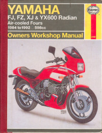
Руководство на английском языке по техническому обслуживанию и ремонту мотоциклов Yamaha моделей FJ600, FZ600, XJ600 и YX600 Radian.
- Издательство: Haynes Publishing
- Год издания: —
- Страниц: 200
- Формат: PDF
- Размер: 89,6 Mb
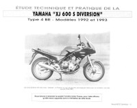
Руководство на французском языке по техническому обслуживанию и ремонту мотоциклов Yamaha XJ600S Diversion 1992-1993 годов выпуска.
- Издательство: —
- Год издания: —
- Страниц: 78
- Формат: JPG
- Размер: 36,7 Mb

Руководство на английском языке по техническому обслуживанию и ремонту мотоциклов Yamaha моделей XJ600S Diversion, Seca II 1992-1999 и XJ600N 1995-1999 годов выпуска.
- Издательство: Haynes Publishing
- Год издания: 2001
- Страниц: 162
- Формат: PDF
- Размер: 42,7 Mb
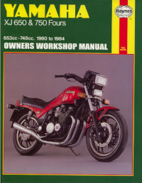
Руководство на английском языке по техническому обслуживанию и ремонту мотоциклов Yamaha моделей XJ650 и XJ750 Fours.
- Издательство: Haynes Publishing
- Год издания: 1994
- Страниц: 277
- Формат: PDF
- Размер: 124,8 Mb
Руководство на английском языке по ремонту мотоциклов Yamaha моделей XJ900S и XJ900SG 1995 года выпуска.
- Издательство: Yamaha Motor Co., Ltd.
- Год издания: —
- Страниц: 352
- Формат: PDF
- Размер: 102,4 Mb

- Manuals
- Brands
- Yamaha Manuals
- Motorcycle
- 2009 Diversion XJ6S
- Service manual
-
Contents
-
Table of Contents
-
Troubleshooting
-
Bookmarks
Related Manuals for Yamaha 2009 Diversion XJ6S
Summary of Contents for Yamaha 2009 Diversion XJ6S
-
Page 1
2009 SERVICE MANUAL XJ6S(Y) XJ6SA 36C-28197-E0… -
Page 3
EAS20040 XJ6S(Y) XJ6SA SERVICE MANUAL ©2009 by Yamaha Motor Co., Ltd. First edition, January 2009 All rights reserved. Any reproduction or unauthorized use without the written permission of Yamaha Motor Co., Ltd. is expressly prohibited. -
Page 4
EAS20071 IMPORTANT This manual was produced by the Yamaha Motor Company, Ltd. primarily for use by Yamaha dealers and their qualified mechanics. It is not possible to include all the knowledge of a mechanic in one man- ual. Therefore, anyone who uses this book to perform maintenance and repairs on Yamaha vehicles should have a basic understanding of mechanics and the techniques to repair these types of vehicles. -
Page 5
EAS20090 HOW TO USE THIS MANUAL This manual is intended as a handy, easy-to-read reference book for the mechanic. Comprehensive explanations of all installation, removal, disassembly, assembly, repair and check procedures are laid out with the individual steps in sequential order. The manual is divided into chapters and each chapter is divided into sections. -
Page 6: Symbols
EAS20100 SYMBOLS The following symbols are used in this manual for easier understanding. The following symbols are not relevant to every vehicle. SYMBOL DEFINITION SYMBOL DEFINITION Serviceable with engine mounted Gear oil Filling fluid Molybdenum disulfide oil Lubricant Brake fluid Wheel bearing grease Special tool Tightening torque…
-
Page 7: Table Of Contents
EAS20110 TABLE OF CONTENTS GENERAL INFORMATION SPECIFICATIONS PERIODIC CHECKS AND ADJUSTMENTS CHASSIS ENGINE COOLING SYSTEM FUEL SYSTEM ELECTRICAL SYSTEM TROUBLESHOOTING…
-
Page 9: General Information
GENERAL INFORMATION IDENTIFICATION ………………1-1 VEHICLE IDENTIFICATION NUMBER ……….. 1-1 MODEL LABEL………………1-1 FEATURES………………..1-2 OUTLINE OF FI SYSTEM …………… 1-2 FI SYSTEM………………..1-3 INSTRUMENT FUNCTIONS …………..1-4 OUTLINE OF THE ABS…………….1-7 ABS COMPONENT FUNCTIONS …………1-11 ABS OPERATION ………………. 1-16 ABS SELF-DIAGNOSIS FUNCTION…………
-
Page 10: Identification
IDENTIFICATION EAS20130 IDENTIFICATION EAS20140 VEHICLE IDENTIFICATION NUMBER The vehicle identification number “1” is stamped into the right side of the steering head pipe. EAS20150 MODEL LABEL The model label “1” is affixed to the frame. This information will be needed to order spare parts.
-
Page 11: Features
FEATURES EAS20170 FEATURES EAS4B51038 OUTLINE OF FI SYSTEM The main function of a fuel supply system is to provide fuel to the combustion chamber at the optimum air-fuel ratio in accordance with the engine operating conditions. In a conventional carburetor system, the air-fuel ratio of the mixture that is supplied to the combustion chamber is created by the volume of the intake air and the fuel that is metered by the jet used in the respective chamber.
-
Page 12: Fi System
FEATURES EAS4B51039 FI SYSTEM The fuel pump delivers fuel to the fuel injector via the fuel filter. The pressure regulator (in the fuel pump) maintains the fuel pressure that is applied to the fuel injector at 245–255 kPa (2.45–2.55 kgf/ , 35.5–37.0 psi) higher than the intake manifold pressure.
-
Page 13: Instrument Functions
FEATURES Tachometer EAS20S1001 INSTRUMENT FUNCTIONS Multi-function meter unit 8 7 6 1. Tachometer 2. Tachometer red zone 1. Fuel meter The electric tachometer allows the rider to mon- 2. Coolant temperature display 3. Speedometer itor the engine speed and keep it within the ideal 4.
-
Page 14
FEATURES Odometer and tripmeter modes system. If a problem is detected in the electrical circuit, the following cycle is repeated until the malfunction is corrected: fuel level segments and symbol “ ” flash eight times, then go off for approximately 3 seconds. If this occurs, check the electrical circuit. -
Page 15
FEATURES 1. Use the code re-registering key to start the engine. Make sure there are no other immobilizer keys close to the main switch, and do not keep more than one immobilizer key on the same key ring! Immobilizer system keys may cause signal inter- ference, which may prevent the engine from starting. -
Page 16: Outline Of The Abs
4. Rear wheel sensor The operation of the Yamaha ABS brakes is the same as conventional brakes on other vehicles, with a front brake lever for operating the front brake and a rear brake pedal for operating the rear brake.
-
Page 17
FEATURES Side force: The force on the tires which supports the vehicle when cornering. Slip ratio: When the brakes are applied, slipping occurs between the tires and the road surface. This causes a difference between the wheel speed and the chassis speed. Slip ratio is the value that shows the rate of wheel slippage and is defined by the following formula. -
Page 18
FEATURES The difference between the chassis speed and the wheel speed calculated in the slip ratio formula is equal to the wheel slip. When the wheel speed is suddenly reduced, the wheel has a tendency to lock. When the wheel slip and the wheel speed reduction rate exceed the preset values, the ABS ECU de- termines that the wheel has a tendency to lock. -
Page 19
Slip ratio (%) b. Brake force Electronic ABS features The Yamaha ABS (anti-lock brake system) has been developed with the most advanced electronic technology. The ABS control is processed with good response under various vehicle travel conditions. The ABS also includes a highly developed self-diagnosis function. The ABS detects any problem con- dition and allows normal braking even if the ABS is not operating properly. -
Page 20: Abs Component Functions
FEATURES ABS block diagram 8. ABS ECU 1. Rear brake master cylinder 9. Buffer chamber 2. Hydraulic unit assembly 10. Rear brake caliper 3. Front brake master cylinder 11. Rear wheel sensor 4. Inlet solenoid valve 12. ABS warning light 5.
-
Page 21
FEATURES 6. Wheel sensor rotor 3. At low speed 7. Voltage 4. At high speed 8. Time 5. Wheel sensor ABS warning light The ABS warning light “1” comes on to warn the rider if a malfunction in the ABS occurs. When the main switch is turned to “ON”, the ABS warning light comes on for 2 seconds, then goes off, so that the rider can check if the ABS warning light is disconnected and check if the ABS is operating properly. -
Page 22
FEATURES Hydraulic control valve The hydraulic control valve is composed of a inlet solenoid valve and outlet solenoid valve. The electromagnetic force generated in the inlet solenoid valve varies proportionally with the duty cycle control voltage that is supplied to it. Since this voltage is continuously variable, the solenoid valve moves smoothly and the hydraulic pressure is adjusted linearly. -
Page 23
FEATURES Buffer chamber The buffer chamber accumulates the brake fluid that is depressurized while the ABS is operating. 1. Buffer chamber (pressurizing phase) 2. Buffer chamber (depressurizing phase) 3. Raised piston 1-14… -
Page 24
FEATURES ABS ECU The ABS ECU is integrated with the hydraulic unit to achieve a compact and lightweight design. As shown in the block following diagram, the ABS ECU receives wheel sensor signals from the front and rear wheels and also receives signals from other monitor circuits. 16 17 18 19 17. -
Page 25: Abs Operation
FEATURES Some types of malfunctions are not recorded in the memory of the ABS ECU (e.g., a blown ABS ECU fuse). The ABS performs a self-diagnosis test for a few seconds each time the vehicle first starts off after the main switch was turned on. During this test, a “clicking” noise can be heard from under the seat and if the front brake lever or rear brake pedal are even slightly applied, a vibration can be felt at the lever or pedal, but these do not indicate a malfunction.
-
Page 26
FEATURES Normal braking (ABS not activated) When the ABS is not activated, the inlet solenoid valve is open and the outlet solenoid valve is closed because a control signal has not been transmitted from the ABS ECU. Therefore, when the brake lever is squeezed, the hydraulic pressure in the brake master cylinder increases and the brake fluid is sent to the brake caliper. -
Page 27
FEATURES Emergency braking (ABS activated) 1. Depressurizing phase When the front wheel is about to lock, the outlet solenoid valve is opened by the “depressurization” signal transmitted from the ABS ECU. When this occurs, the inlet solenoid valve compresses the spring and closes the brake line from the brake master cylinder. -
Page 28: Abs Self-Diagnosis Function
FEATURES 8. Brake caliper 1. Brake master cylinder 9. Wheel sensor 2. Brake light switch 10. ABS ECU 3. ABS motor 11. ABS warning light 4. Hydraulic pump 12. Brake fluid pressure 5. Buffer chamber 13. Time 6. Outlet solenoid valve 7.
-
Page 29
FEATURES Instances when the ABS warning light comes on 1. The ABS warning light comes on when the main switch is turned to “ON”. The ABS warning light comes on for 2 seconds while the ABS is performing a self-diagnosis, then goes off if there are no problems. -
Page 30
FEATURES a. ABS warning light b. Comes on 4. The ABS warning light flashes while riding. If the ABS warning light flashes while riding, there is no problem with the function of the ABS. How- ever, the ABS ECU input has unstable factors. (For details, refer to “ABS TROUBLESHOOTING OUTLINE”… -
Page 31: Abs Warning Light And Operation
FEATURES EAS4B56012 ABS WARNING LIGHT AND OPERATION ABS warning light When the main switch is turned to “ON”, the ABS warning light comes on for 2 seconds, then goes off. The ABS warning light comes on while the start switch is being pushed. If the ABS warning light comes on while riding, stop the vehicle, and then turn the main switch to “OFF”, then back to “ON”.
-
Page 32
FEATURES and tires is close to the limit. The ABS cannot prevent wheel lock* on slippery surfaces, such as ice, when it is caused by engine braking, even if the ABS is activated. The ABS is not designed to shorten the braking distance or improve the cornering perfor- mance. -
Page 33: Important Information
5. Keep all parts away from any source of fire. EAS20200 REPLACEMENT PARTS Use only genuine Yamaha parts for all replace- ments. Use oil and grease recommended by Yamaha for all lubrication jobs. Other brands may be similar in function and appearance, but inferior in quality.
-
Page 34: Bearings And Oil Seals
IMPORTANT INFORMATION EAS20230 BEARINGS AND OIL SEALS Install bearings “1” and oil seals “2” so that the manufacturer’s marks or numbers are visible. When installing oil seals, lubricate the oil seal lips with a light coat of lithium-soap-based grease. Oil bearings liberally when installing, if appropriate.
-
Page 35: Checking The Connections
CHECKING THE CONNECTIONS EAS20250 CHECKING THE CONNECTIONS ECA20S1001 NOTICE Electronic parts are very sensitive. Handle with care and do not give impact. When you check the electric system of a motor- cycle, check the battery voltage before. Mini- mum 11V is requested to check each component function.
-
Page 36: Removing The Quick Fastener
CHECKING THE CONNECTIONS If the pin “1” on the terminal is flattened, bend it If the contact seems not good, pull the terminal by hand and check its condition. When you check the voltage or electrical conti- nuity, insert the measuring probe from back side as you can insert from back side.
-
Page 37: Installing The Quick Fastener
CHECKING THE CONNECTIONS EAS21850 INSTALLING THE QUICK FASTENER To install the quick fastener, push its pin so that it protrudes from the fastener head, then insert the fastener into the cover and push the pin “a” in with screwdriver. Make sure that the pin is flush with the fastener’s head.
-
Page 38: Special Tools
SPECIAL TOOLS EAS20260 SPECIAL TOOLS The following special tools are necessary for complete and accurate tune-up and assembly. Use only the appropriate special tools as this will help prevent damage caused by the use of inappropriate tools or improvised techniques. Special tools, part numbers or both may differ depending on the country. When placing an order, refer to the list provided below to avoid any mistakes.
-
Page 39
SPECIAL TOOLS Reference Tool name/Tool No. Illustration pages Pressure gauge 3-26, 7-7, 7-9 90890-03153 YU-03153 Oil pressure adapter H 3-26 90890-03139 Compression gauge 5-18 90890-03081 Engine compression tester YU-33223 Steering nut wrench 3-19, 4-70 90890-01403 Spanner wrench YU-33975 Damper rod holder 4-63, 4-65 90890-01460 T-handle… -
Page 40
SPECIAL TOOLS Reference Tool name/Tool No. Illustration pages Fork seal driver weight 4-65, 4-66 90890-01367 Replacement hammer YM-A9409-7 Fork seal driver attachment (ø41) 4-65 90890-01381 Replacement 41 mm YM-A5142-2 Ring nut wrench 4-70 90890-01268 Spanner wrench YU-1268 Valve spring compressor 5-21, 5-26 90890-04019 YM-04019… -
Page 41
YM-04113 Sheave holder 5-30, 5-31, 90890-01701 5-32 Primary clutch holder YS-01880-A Flywheel puller 5-30 90890-01362 Heavy duty puller YU-33270-B Flywheel puller attachment 5-30 90890-04089 Crankshaft protector YM-33282 Yamaha bond No. 1215 5-32, 5-34, (Three bond No.1215®) 5-61, 6-12 90890-85505 1-32… -
Page 42
SPECIAL TOOLS Reference Tool name/Tool No. Illustration pages Camshaft wrench 5-34 90890-04143 YM-04143 Digital circuit tester 5-38, 7-10, 90890-03174 8-143, 8-152, Model 88 Multimeter with tachometer 8-153, 8-157, YU-A1927 8-158, 8-160, 8-161, 8-162, 8-163, 8-164, 8-165, 8-166, 8-167, 8-168 Universal clutch holder 5-50, 5-54 90890-04086 YM-91042… -
Page 43
SPECIAL TOOLS Reference Tool name/Tool No. Illustration pages Radiator cap tester 90890-01325 Radiator pressure tester YU-24460-01 YU-24460-01 Radiator cap tester adapter 90890-01352 Radiator pressure tester adapter YU-33984 YU-33984 Mechanical seal installer 6-12 90890-04078 Water pump seal installer YM-33221-A Middle driven shaft bearing driver 6-12 90890-04058 Bearing driver 40 mm… -
Page 44
SPECIAL TOOLS Reference Tool name/Tool No. Illustration pages Fuel pressure adapter 90890-03176 YM-03176 Ignition checker 8-160 90890-06754 Opama pet-4000 spark checker YM-34487 1-35… -
Page 45: Specifications
SPECIFICATIONS GENERAL SPECIFICATIONS …………..2-1 ENGINE SPECIFICATIONS …………….2-2 CHASSIS SPECIFICATIONS ……………. 2-9 ELECTRICAL SPECIFICATIONS …………..2-12 TIGHTENING TORQUES …………….2-15 GENERAL TIGHTENING TORQUE SPECIFICATIONS ……2-15 ENGINE TIGHTENING TORQUES …………2-15 CHASSIS TIGHTENING TORQUES …………2-19 LUBRICATION POINTS AND LUBRICANT TYPES ……..2-24 ENGINE ………………..
-
Page 46: General Specifications
GENERAL SPECIFICATIONS EAS20280 GENERAL SPECIFICATIONS Model Model XJ6S 36C1 XJ6SA 36D1 XJ6SY 36C2 Dimensions Overall length 2120 mm (83.5 in) Overall width 770 mm (30.3 in) Overall height 1210 mm (47.6 in) Seat height 785 mm (30.9 in) Wheelbase 1440 mm (56.7 in) Ground clearance 140 mm (5.51 in) Minimum turning radius…
-
Page 47: Engine Specifications
ENGINE SPECIFICATIONS EAS20290 ENGINE SPECIFICATIONS Engine Engine type Liquid cooled 4-stroke, DOHC Displacement 599.8 cm Cylinder arrangement Forward-inclined parallel 4-cylinder Bore × stroke 65.5 × 44.5 mm (2.58 × 1.75 in) Compression ratio 12.20 :1 Standard compression pressure (at sea level) 1550 kPa/400 r/min (15.5 kgf/cm /400 r/min, 220.5 psi/400 r/min)
-
Page 48
ENGINE SPECIFICATIONS Depth 22.0 mm (0.87 in) Water pump Water pump type Single suction centrifugal pump 86/44 × 31/31 (1.955) Reduction ratio Spark plug (s) Manufacturer/model NGK/CR9E Spark plug gap 0.7–0.8 mm (0.028–0.031 in) Cylinder head Volume 10.33–10.93 cm (0.63–0.67 cu.in) Warpage limit 0.05 mm (0.0020 in) Camshaft… -
Page 49
ENGINE SPECIFICATIONS Valve dimensions Valve head diameter A (intake) 24.90–25.10 mm (0.9803–0.9882 in) Valve head diameter A (exhaust) 21.90–22.10 mm (0.8622–0.8701 in) Valve face width B (intake) 1.210–2.490 mm (0.0476–0.0980 in) Valve face width B (exhaust) 1.210–2.490 mm (0.0476–0.0980 in) Valve seat width C (intake) 0.90–1.10 mm (0.0354–0.0433 in) Limit… -
Page 50
ENGINE SPECIFICATIONS Free length (intake) 39.08 mm (1.54 in) Free length (exhaust) 39.08 mm (1.54 in) Installed length (intake) 33.40 mm (1.31 in) Installed length (exhaust) 33.40 mm (1.31 in) Spring rate K1 (intake) 25.05 N/mm (2.55 kgf/mm, 143.04 lb/in) Spring rate K2 (intake) 40.82 N/mm (4.16 kgf/mm, 233.08 lb/in) Spring rate K1 (exhaust) -
Page 51
ENGINE SPECIFICATIONS Piston ring Top ring Ring type Barrel Dimensions (B × T) 0.90 × 2.45 mm (0.04 × 0.10 in) End gap (installed) 0.25–0.35 mm (0.0098–0.0138 in) Ring side clearance 0.030–0.065 mm (0.0012–0.0026 in) 2nd ring Ring type Barrel Dimensions (B ×… -
Page 52
ENGINE SPECIFICATIONS Wear limit 2.80 mm (0.1102 in) Plate quantity 6 pcs Friction plate thickness 2.92–3.08 mm (0.115–0.121 in) Wear limit 2.80 mm (0.1102 in) Plate quantity 1 pcs Friction plate thickness 2.94–3.06 mm (0.116–0.120 in) Water limit 2.84 mm (0.1118 in) Plate quantity 1 pcs Clutch plate thickness… -
Page 53
ENGINE SPECIFICATIONS Idling condition Engine idling speed 1250–1350 r/min 4.5–5.5 % Intake vacuum 32.0 kPa (238 mmHg, 9.37 inHg) 95.0–105.0 °C (203.00–221.00 °F) Water temperature 75.0–85.0 °C (167.00–185.00 °F) Oil temperature Throttle cable free play 3.0–5.0 mm (0.12–0.20 in) -
Page 54: Chassis Specifications
CHASSIS SPECIFICATIONS EAS20300 CHASSIS SPECIFICATIONS Chassis Frame type Diamond 26.00 ° Caster angle Trail 103.5 mm (4.08 in) Front wheel Wheel type Cast wheel Rim size 17M/C x MT3.50 Rim material Aluminum Wheel travel 130.0 mm (5.12 in) Radial wheel runout limit 1.0 mm (0.04 in) Lateral wheel runout limit 0.5 mm (0.02 in)
-
Page 55
CHASSIS SPECIFICATIONS Brake disc thickness limit 4.0 mm (0.16 in) Brake disc deflection limit 0.10 mm (0.0039 in) Brake pad lining thickness (inner) 6.0 mm (0.24 in) Limit 0.8 mm (0.03 in) Brake pad lining thickness (outer) 6.0 mm (0.24 in) Limit 0.8 mm (0.03 in) Master cylinder inside diameter… -
Page 56
CHASSIS SPECIFICATIONS Spring free length 177.5 mm (6.99 in) Installed length 165.5 mm (6.52 in) Spring rate K1 176.50 N/mm (18.00 kgf/mm, 1007.82 lb/in) Spring stroke K1 0.0–42.0 mm (0.00–1.65 in) Optional spring available Enclosed gas/air pressure (STD) 1500 kPa (15.0 kgf/cm , 213.3 psi) Spring preload adjusting positions Minimum… -
Page 57: Electrical Specifications
ELECTRICAL SPECIFICATIONS EAS20310 ELECTRICAL SPECIFICATIONS Voltage System voltage 12 V Ignition system Ignition system TCI (digital) Advancer type Digital 6.5 °/1300 r/min Ignition timing (B.T.D.C.) Engine control unit Model/manufacturer XJ6S/XJ6SY FUA0030/MITSUBISHI XJ6SA FUA0031/MITSUBISHI Crankshaft position sensor 248–372 Ω (Gy-B) Crankshaft position sensor resistance Ignition coil Minimum ignition spark gap 6.0 mm (0.24 in)
-
Page 58
ELECTRICAL SPECIFICATIONS Coolant temperature warning light Engine trouble warning light ABS warning light XJ6SA LED Immobilizer system indicator light Electric starting system System type Constant mesh Starter motor Power output 0.60 kW 0.0012–0.0022 Ω Armature coil resistance Brush overall length 10.0 mm (0.39 in) Limit 3.50 mm (0.14 in) -
Page 59
ELECTRICAL SPECIFICATIONS Spare fuse XJ6S/XJ6SY 30.0 A XJ6SA 30.0 A×2 Spare fuse 20.0 A Spare fuse 10.0 A 7.5 A 2-14… -
Page 60: Tightening Torques
TIGHTENING TORQUES EAS20320 TIGHTENING TORQUES EAS20330 GENERAL TIGHTENING TORQUE SPECIFICATIONS This chart specifies tightening torques for stan- dard fasteners with a standard ISO thread pitch. Tightening torque specifications for special com- ponents or assemblies are provided for each chapter of this manual. To avoid warpage, tight- en multi-fastener assemblies in a crisscross pat- A.
-
Page 61
TIGHTENING TORQUES Thread ’ Item Tightening torque Remarks size · · Thermostat cover bolt 12 Nm (1.2 m kgf, 8.7 ft lbf) · · Water jacket joint bolt 10 Nm (1.0 m kgf, 7.2 ft lbf) · · Water pump cover bolt 10 Nm (1.0 m kgf, 7.2 ft lbf) -
Page 62
TIGHTENING TORQUES Thread ’ Item Tightening torque Remarks size · · Muffler cap 10 Nm (1.0 m kgf, 7.2 ft lbf) · · Clutch cover bolt 10 Nm (1.0 m kgf, 7.2 ft lbf) · · Generator cover bolt 10 Nm (1.0 m kgf, 7.2 ft lbf) Apply oil… -
Page 63
TIGHTENING TORQUES Thread ’ Item Tightening torque Remarks size · · Crankshaft position sensor bolt 10 Nm (1.0 m kgf, 7.2 ft lbf) · · Starter clutch screw 32 Nm (3.2 m kgf, 23 ft lbf) · · Starter motor assembly bolt 3.4 Nm (0.34 m kgf, 2.3 ft lbf) -
Page 64: Chassis Tightening Torques
TIGHTENING TORQUES Tighten at 75°–85° angle according to the tightening order (“8”, “9”). Cylinder head tightening sequence. Crankcase tightening sequence. EAS20350 CHASSIS TIGHTENING TORQUES Threa Item Q’ty Tightening torque Remarks d size · · Upper bracket pinch bolt 20 Nm (2.0 m kgf, 14 ft lbf) ·…
-
Page 65
TIGHTENING TORQUES Threa Item Q’ty Tightening torque Remarks d size · · Right handlebar switch screw 4 Nm (0.4 m kgf, 2.9 ft lbf) · · Steering stem nut 110 Nm (11 m kgf, 80 ft lbf) · · Upper handlebar holder bolt 24 Nm (2.4 m kgf, 17 ft lbf) -
Page 66
TIGHTENING TORQUES Threa Item Q’ty Tightening torque Remarks d size · · Fuel tank and fuel tank cap 6 Nm (0.6 m kgf, 4.3 ft lbf) · · Fuel pump and fuel tank 4 Nm (0.4 m kgf, 2.9 ft lbf) ·… -
Page 67
TIGHTENING TORQUES Threa Item Q’ty Tightening torque Remarks d size · · Brake pedal and footrest bracket 7 Nm (0.7 m kgf, 5.0 ft lbf) · · Footrest bolt 10 Nm (1.0 m kgf, 7.2 ft lbf) · · Footrest bracket and frame 30 Nm (3.0 m kgf, 22 ft lbf) -
Page 68
TIGHTENING TORQUES Threa Item Q’ty Tightening torque Remarks d size · · Brake hose union bolt (with ABS) 30 Nm (3.0 m kgf, 22 ft lbf) Brake pipe/joint assembly flare nut · · 16 Nm (1.6 m kgf, 11 ft lbf) (with ABS) Lower ring nut… -
Page 69: Lubrication Points And Lubricant Types
LUBRICATION POINTS AND LUBRICANT TYPES EAS20360 LUBRICATION POINTS AND LUBRICANT TYPES EAS20370 ENGINE Lubrication point Lubricant Oil seal lips O-rings Bearings and bushes Crankshaft pins Piston surfaces Piston pins Connecting rod bolts Crankshaft journals Camshaft profile journals Valve stems (intake and exhaust) Valve stem ends (intake and exhaust) Valve lifter surface Piston cooler (O-ring)
-
Page 70: Chassis
LUBRICATION POINTS AND LUBRICANT TYPES Lubrication point Lubricant ® Cylinder head cover semicircular Three bond No.1215B ® Crankcase mating surface Three bond No.1215 ® Generator rotor cover (stator coil assembly lead grommet) Three bond No.1215 Pickup rotor cover (crankshaft position sensor lead grommet) Three bond No.1215®…
-
Page 71
LUBRICATION POINTS AND LUBRICANT TYPES 2-26… -
Page 72: Lubrication System Chart And Diagrams
LUBRICATION SYSTEM CHART AND DIAGRAMS EAS20390 LUBRICATION SYSTEM CHART AND DIAGRAMS EAS20400 ENGINE OIL LUBRICATION CHART 2-27…
-
Page 73
LUBRICATION SYSTEM CHART AND DIAGRAMS 1. Oil strainer 2. Oil pump 3. Relief valve 4. Oil filter 5. Oil cooler 6. Main axle 7. Oil pipe 8. Drive axle 9. Main gallery 10. Oil nozzle 11. Timing chain tensioner 12. Intake camshaft 13. -
Page 74: Lubrication Diagrams
LUBRICATION SYSTEM CHART AND DIAGRAMS EAS20410 LUBRICATION DIAGRAMS 2-29…
-
Page 75
LUBRICATION SYSTEM CHART AND DIAGRAMS 1. Oil level switch 2. Oil cooler 3. Relief valve 4. Ventilation chamber cover 5. Oil delivery pipe 2-30… -
Page 76
LUBRICATION SYSTEM CHART AND DIAGRAMS 2-31… -
Page 77
LUBRICATION SYSTEM CHART AND DIAGRAMS 1. Oil pump 2. Exhaust camshaft 3. Intake camshaft 4. Oil strainer 5. Oil pipe 6. Oil delivery pipe 7. Timing chain tensioner 8. Oil check bolt 2-32… -
Page 78
LUBRICATION SYSTEM CHART AND DIAGRAMS 2-33… -
Page 79
LUBRICATION SYSTEM CHART AND DIAGRAMS 1. Oil cooler 2. Oil strainer 3. Oil level switch 4. Oil pump 5. Oil pipe 6. Oil filter 2-34… -
Page 80
LUBRICATION SYSTEM CHART AND DIAGRAMS 2-35… -
Page 81
LUBRICATION SYSTEM CHART AND DIAGRAMS 1. Main axle 2. Oil pump 3. Relief valve 4. Oil pipe 5. Oil delivery pipe 2-36… -
Page 82
LUBRICATION SYSTEM CHART AND DIAGRAMS 2-37… -
Page 83
LUBRICATION SYSTEM CHART AND DIAGRAMS 1. Cylinder head 2. Intake camshaft 3. Exhaust camshaft 4. Crankshaft 5. Oil nozzle 2-38… -
Page 84
LUBRICATION SYSTEM CHART AND DIAGRAMS 2-39… -
Page 85
LUBRICATION SYSTEM CHART AND DIAGRAMS 1. Main axle 2. Drive axle 3. Oil pipe 2-40… -
Page 86: Cooling System Diagrams
COOLING SYSTEM DIAGRAMS EAS20420 COOLING SYSTEM DIAGRAMS 2-41…
-
Page 87
COOLING SYSTEM DIAGRAMS 1. Radiator 2. Oil cooler 3. Water pump 4. Coolant reservoir 5. Fast idle plunger 6. Water pump breather hose 7. Water jacket joint 2-42… -
Page 88: Cable Routing
CABLE ROUTING EAS20430 CABLE ROUTING 2-43…
-
Page 89
CABLE ROUTING 1. Clutch cable 2. Throttle cable (accelerator side) 3. Throttle cable (decelerator side) A. Clamp the left handlebar switch lead, main switch lead, immobilizer lead, and throttle cables. Clamp the leads at the white tape position. Direct the end of clamp down and outward.No need to cut off its end. -
Page 90
CABLE ROUTING 2-45… -
Page 91
CABLE ROUTING 1. Fuel tank drain hose 2. Rear mudguard assembly 3. ECU lead 4. Starter motor lead 5. Oil level switch lead 6. Sidestand switch lead 7. Sub-wire harness (throttle body) 8. Throttle body joint coupler 9. Wire harness A. -
Page 92
CABLE ROUTING 2-47… -
Page 93
CABLE ROUTING 1. Right handlebar switch lead 2. Radiator fan motor lead 3. Ignition coil #2, #3 connector 4. Main switch lead 2 5. Main switch lead 1 6. Immobilizer lead 7. Left handlebar switch lead 8. Ignition coil #1, #4 connector 9. -
Page 94
CABLE ROUTING 2-49… -
Page 95
CABLE ROUTING 1. Fuel tank breather hose 2. Rectifier/regulator 3. Battery negative lead 4. Starter relay 5. Battery positive lead 6. Starter motor lead 7. Fuel tank drain hose 8. Throttle body joint coupler A. To crankshaft position sensor B. To AC magneto C. -
Page 96
CABLE ROUTING 2-51… -
Page 97
CABLE ROUTING 1. Radiator fan motor relay 2. Relay unit 3. License plate light lead 4. Rear turn signal light leads (left/right) 5. Tail/brake light lead 6. Seat lock cable 7. Turn signal relay 8. Headlight relay 9. Lean angle sensor 10. -
Page 98
CABLE ROUTING 2-53… -
Page 99
CABLE ROUTING 1. Front brake hose 2. Front fork assembly A. Clamp it securely. The pawl must be directed toward the right side of the vehicle. B. Insert it securely until it reaches its end position. C. Secure for 3 or more notches. The pawl must be directed toward the front of the vehicle. -
Page 100
CABLE ROUTING 2-55… -
Page 101
CABLE ROUTING 1. Rear brake caliper 2. Dust cover 3. Rear brake hose 4. Rear brake reservoir 5. Rear brake light switch lead 6. Frame complete 7. Swingarm A. Clamp it securely. The pawl must be directed toward the rear of the vehicle. B. -
Page 102
CABLE ROUTING 2-57… -
Page 103
CABLE ROUTING 1. Clutch cable 2. Front brake pipe 3. Throttle cable (accelerator side) 4. Throttle cable (decelerator side) 5. Front wheel sensor lead A. Clamp the left handlebar switch lead, main switch lead, immobilizer lead, and throttle cables. Clamp the leads at the white tape position. -
Page 104
CABLE ROUTING 2-59… -
Page 105
CABLE ROUTING 1. Fuel tank drain hose 2. Rear mudguard assembly 3. ECU lead 4. Starter motor lead 5. Oil level switch lead 6. Sidestand switch lead 7. Sub-wire harness (throttle body) 8. Throttle body joint connector 9. Wire harness A. -
Page 106
CABLE ROUTING 2-61… -
Page 107
CABLE ROUTING 1. Right handlebar switch lead 2. Radiator fan motor lead 3. Ignition coil #2, #3 connector 4. Main switch lead 2 5. Main switch lead 1 6. Immobilizer lead 7. Left handlebar switch lead 8. Front wheel sensor lead 9. -
Page 108
CABLE ROUTING 2-63… -
Page 109
CABLE ROUTING 1. Fuel tank breather hose 2. Rectifier/regulator 3. Battery negative lead 4. Starter relay 5. Starter motor lead 6. Battery positive lead 7. Fuel tank drain hose 8. Throttle body joint coupler A. To crankshaft position sensor B. To AC magneto C. -
Page 110
CABLE ROUTING 2-65… -
Page 111
CABLE ROUTING 1. Radiator fan motor relay 2. Relay unit 3. License plate light lead 4. Rear turn signal light leads (left/right) 5. Tail/brake light lead 6. Seat lock cable 7. Turn signal relay 8. Headlight relay 9. Lean angle sensor 10. -
Page 112
CABLE ROUTING 2-67… -
Page 113
CABLE ROUTING 1. Front wheel sensor lead 2. Front brake pipe (front brake master cylin- der–hydraulic unit) 3. Brake pipe holder 4. Hydraulic unit 5. Front brake pipe (front brake caliper–hydraulic unit) 6. Frame 7. Radiator assembly 8. Front brake hose 9. -
Page 114
CABLE ROUTING 2-69… -
Page 115
CABLE ROUTING 1. Front brake hose 2. Front fork assembly 3. Front brake caliper 4. Front wheel sensor lead 5. Clamp A. Clamp securely. The pawl must be directed toward the right side of the vehicle. B. Insert it securely until it reaches its end position. C. -
Page 116
CABLE ROUTING 2-71… -
Page 117
CABLE ROUTING 1. Rear wheel sensor housing 2. Rear wheel sensor 3. Rear brake caliper 4. Clamp 5. Rear brake hose (rear brake caliper–hydraulic unit) 6. Rear wheel sensor lead 7. Rear brake hose (rear brake master cylin- der–hydraulic unit) 8. -
Page 118
CABLE ROUTING 2-73… -
Page 119
CABLE ROUTING 1. Rear wheel sensor 2. Clamp 3. Rear brake pipe (hydraulic unit–rear brake cali- per) 4. Rear brake pipe (rear brake master cylin- der–hydraulic unit) 5. Hydraulic unit 6. Wire harness 7. Front brake pipe (front brake master cylin- der–hydraulic unit) 8. -
Page 120
CABLE ROUTING 2-75… -
Page 121
CABLE ROUTING 1. Rear wheel sensor 2. Clamp 3. Wire harness 4. Front brake pipe (hydraulic unit–front brake cali- per) 5. Front brake pipe (front brake master cylin- der–hydraulic unit) 6. Frame 7. Hydraulic unit 8. Rear brake hose (rear brake master cylin- der–hydraulic unit) 9. -
Page 122
CABLE ROUTING 2-77… -
Page 123
CABLE ROUTING 1. Clutch cable 2. Left handlebar switch lead 3. Horn lead 4. Throttle cables 5. Right handlebar switch lead 6. Cable guide A. Clamp the main switch lead and immobilizer lead on to the left side of the cable guide where it is not curved. -
Page 124
CABLE ROUTING 2-79… -
Page 125
CABLE ROUTING 1. Radiator fan motor lead 2. Crankshaft position sensor lead 3. Wire harness 4. Connector cover A. To meter B. To headlight C. Clamp the wire harness, right handlebar switch lead, and radiator fan motor lead. Clamp the right handlebar switch lead so that there is no slack when the handle is all the way turned to the left. -
Page 126
CABLE ROUTING 2-81… -
Page 127
CABLE ROUTING 1. Battery negative lead 2. Rear brake light switch lead 3. Fuel tank breather hose 4. O sensor lead 5. Neutral switch lead 6. Rear turn signal light lead (right/left) 7. License plate light lead 8. Tail/brake light lead A. -
Page 128
CABLE ROUTING 2-83… -
Page 129
CABLE ROUTING 1. Fuel tank cap 2. Fuel tank 3. Fuel pump 4. Fuel hose 5. Fuel tank breather hose (right side) 6. Fuel tank drain hose (left side) 7. Throttle body 8. Fuel hose connector 9. Fuel pump bracket 10. -
Page 130
CABLE ROUTING 2-85… -
Page 131
CABLE ROUTING 1. Synchronizing hose #1 2. Synchronizing hose #2 3. Synchronizing hose #3 4. Synchronizing hose #4 5. Fast idle plunger coolant hose 6. Throttle position sensor 7. Fuel injector #4 8. Intake air pressure sensor 9. Fuel injector #3 10. -
Page 132
CABLE ROUTING 2-87… -
Page 133
CABLE ROUTING 1. Fast idle plunger coolant hose 2. Fast idle plunger 3. Synchronizing hose #1 4. Synchronizing hose #2 5. Fast idle plunger hose (fast idle plunger-throttle body #1) 6. Intake air pressure sensor 7. Throttle position sensor 8. Fast idle plunger hose (fast idle plunger-throttle body #4) 9. -
Page 134
CABLE ROUTING 2-89… -
Page 135
CABLE ROUTING 1. Air cut-off valve hose 1 2. Air cut-off valve hose 2 3. Air cut-off valve 4. Air cut-off valve hose 3 5. Air filter case 6. Bracket 7. Rubber cover 8. Reed valve A. Install the clamp with its end facing the right side of the vehicle. -
Page 136
CABLE ROUTING 2-91… -
Page 137: Periodic Checks And Adjustments
PERIODIC CHECKS AND ADJUSTMENTS PERIODIC MAINTENANCE …………….3-1 INTRODUCTION ………………3-1 PERIODIC MAINTENANCE CHART FOR THE EMISSION CONTROL SYSTEM …………….3-1 GENERAL MAINTENANCE AND LUBRICATION CHART ….. 3-2 CHECKING THE FUEL LINE …………..3-4 CHECKING THE SPARK PLUGS …………3-4 ADJUSTING THE VALVE CLEARANCE ……….
-
Page 138: Periodic Maintenance
UK, a mileage-based maintenance, is performed instead. From 50000 km (30000 mi), repeat the maintenance intervals starting from 10000 km (6000 mi). Items marked with an asterisk should be performed by a Yamaha dealer as they require special tools, data and technical skills.
-
Page 139: General Maintenance And Lubrication Chart
PERIODIC MAINTENANCE EAU1770B GENERAL MAINTENANCE AND LUBRICATION CHART ODOMETER READING CHECK OR MAINTENANCE ANNUAL ITEM CHECK 1000 km 10000 km 20000 km 30000 km 40000 km (600 mi) (6000 mi) (12000 mi) (18000 mi) (24000 mi) √ Air filter element Replace.
-
Page 140
PERIODIC MAINTENANCE ODOMETER READING CHECK OR MAINTENANCE ANNUAL ITEM CHECK 1000 km 10000 km 20000 km 30000 km 40000 km (600 mi) (6000 mi) (12000 mi) (18000 mi) (24000 mi) Check operation and for oil √ √ √ √ 19 * Front fork leakage. -
Page 141: Checking The Fuel Line
PERIODIC MAINTENANCE 2. Disconnect: EAS21030 CHECKING THE FUEL LINE Spark plug caps The following procedure applies to all of the fuel, 3. Remove: vacuum and breather hoses. Spark plugs 1. Remove: ECA13320 Seat NOTICE Refer to “GENERAL CHASSIS” on page 4-1. Before removing the spark plugs, blow away Fuel tank any dirt accumulated in the spark plug wells…
-
Page 142: Adjusting The Valve Clearance
PERIODIC MAINTENANCE 9. Connect: Spark plug caps 10.Install: Rubber cover Refer to “AIR INDUCTION SYSTEM” on page 7-11. Air filter case Refer to “GENERAL CHASSIS” on page 4-1. Fuel tank Refer to “FUEL TANK” on page 7-1. Seat 4. Measure: Refer to “GENERAL CHASSIS”…
-
Page 143
PERIODIC MAINTENANCE 5. Remove: Thickness gauge Camshafts 90890-03079 Narrow gauge set Refer to “CAMSHAFTS” on page 5-8. YM-34483 When removing the timing chain and cam- shafts, fasten the timing chain with a wire to re- trieve it if it falls into the crankcase. 6. -
Page 144: Adjusting The Engine Idling Speed
PERIODIC MAINTENANCE The thickness “a” of each valve pad is marked in hundredths of millimeters on the side that touch- es the valve lifter. Example: If the valve pad is marked “158”, the pad thickness is 1.58 mm (0.062 in) Lubricate the valve pad with molybdenum dis- ulfide grease.
-
Page 145: Synchronizing The Throttle Bodies
PERIODIC MAINTENANCE Spark plugs Air filter element Throttle body joints Fuel hoses Air induction system Exhaust system Breather hoses Throttle body hoses Fast idle plunger outlet hose Fast idle plunger inlet hose 1. Start the engine and let it warm up for several minutes.
-
Page 146
PERIODIC MAINTENANCE Vacuum gauge 90890-03094 Carburetor synchronizer YU-44456 The difference in vacuum pressure between two throttle bodies should not exceed 1.33 kPa (10 mmHg). 4. Install: Fuel tank Refer to “FUEL TANK” on page 7-1. 5. Start the engine and let it warm up for several minutes. -
Page 147: Checking The Air Induction System
PERIODIC MAINTENANCE EAS20S13005 CHECKING THE AIR INDUCTION SYSTEM Refer to “AIR INDUCTION SYSTEM” on page 7-11. EAS21070 CHECKING THE CRANKCASE BREATHER HOSE 1. Remove: Seat Refer to “GENERAL CHASSIS” on page 4-1. Fuel tank Refer to “FUEL TANK” on page 7-1. 2.
-
Page 148: Adjusting The Clutch Cable Free Play
PERIODIC MAINTENANCE Seat MMMMMMMMMMMMMMMMMMMMMMMMMMMMMMMM Refer to “GENERAL CHASSIS” on page 4-1. Engine side a. Remove the left side cowling and left side EAS20870 panel. ADJUSTING THE CLUTCH CABLE FREE Refer to “GENERAL CHASSIS” on page 4-1. PLAY b. Loosen the locknut “1”. 1.
-
Page 149: Adjusting The Front Disc Brake
PERIODIC MAINTENANCE brake lever) While pushing the brake lever forward, turn the adjusting dial “1” until the brake lever is in the desired position. Be sure to align the setting on the adjusting dial with the arrow mark “2” on the brake lever hold- Position #1 Distance “a”…
-
Page 150: Adjusting The Rear Disc Brake
PERIODIC MAINTENANCE c. Tighten the locknut “1” to specification. EAS21190 ADJUSTING THE REAR DISC BRAKE Locknut 1. Check: 18 Nm (1.8 m·kgf, 13 ft·lbf) Brake pedal position (distance “a” from the top of the rider footrest EWA4S81005 to the top of the brake pedal) WARNING Out of specification →…
-
Page 151: Bleeding The Hydraulic Brake System
PERIODIC MAINTENANCE EAS21340 BLEEDING THE HYDRAULIC BRAKE SYSTEM EWA13100 WARNING Bleed the hydraulic brake system whenever: the system is disassembled. a brake hose is loosened, disconnected or replaced. the brake fluid level is very low. brake operation is faulty. A. Front brake B.
-
Page 152
PERIODIC MAINTENANCE EWA13110 WARNING After bleeding the hydraulic brake system, check the brake operation. LLLLLLLLLLLLLLLLLLLLLLLLLLLLLLLL Bleeding the ABS brake EWA36C1001 WARNING Bleed the ABS whenever: the system is disassembled. a brake hose is loosened, disconnected or replaced. the brake fluid level is very low. brake operation is faulty. -
Page 153: Checking The Front Brake Hoses
PERIODIC MAINTENANCE Front brake caliper bleed screw 6 Nm (0.6 m·kgf, 4.3 ft·lbf) Rear brake caliper bleed screw 5 Nm (0.5 m·kgf, 3.6 ft·lbf) m. Fill the brake master cylinder reservoir or brake fluid reservoir to the proper level with the recommended brake fluid.
-
Page 154
Front en if a tire combination other than one 250 kPa (2.50 kgf/cm , 36 psi) approved by Yamaha is used on this vehicle. Rear 290 kPa (2.90 kgf/cm , 42 psi) Front tire… -
Page 155: Checking The Wheel Bearing
PERIODIC MAINTENANCE 1. Stand the vehicle on a level surface. Rear tire EWA13120 Size WARNING 160/60 ZR17M/C (69W) Securely support the vehicle so that there is Manufacturer/model no danger of it falling over. BRIDGESTONE/BT021 Manufacturer/model DUNLOP/ROADSMART Place the vehicle on the centerstand so that the rear wheel is elevated.
-
Page 156: Lubricating The Drive Chain
PERIODIC MAINTENANCE Place the vehicle on a suitable stand so that the front wheel is elevated. 2. Check: Steering head Grasp the bottom of the front fork legs and gently rock the front fork. Binding/looseness → Adjust the steering head. 3.
-
Page 157: Adjusting The Handlebar Position
PERIODIC MAINTENANCE Lower ring nut (final tightening Make sure all of the cables and wires are prop- torque) erly routed. 18 Nm (1.8 m·kgf, 13 ft·lbf) a. Point the front wheel straight ahead. b. Install a plastic locking tie “1” loosely around the end of the handlebar as shown.
-
Page 158: Lubricating The Levers
PERIODIC MAINTENANCE 2. Adjust: Handlebar position MMMMMMMMMMMMMMMMMMMMMMMMMMMMMMMM a. Remove the handlebar holder caps “1”, up- per handlebar holders “2” and handlebar “3”. Upper handlebar holder bolt 24 Nm (2.4 m·kgf, 17 ft·lbf) ECA14250 NOTICE b. Loosen the lower handlebar holder nuts “4”. First, tighten the bolts on the front side of c.
-
Page 159: Lubricating The Pedal
PERIODIC MAINTENANCE Recommended lubricant Clutch lever Lithium-soap-based grease Brake lever Silicone grease EAS21710 LUBRICATING THE PEDAL Lubricate the pivoting point and metal-to-metal moving parts of the pedal. Recommended lubricant Lithium-soap-based grease EAS21370 ADJUSTING THE SHIFT PEDAL 1. Check: Shift pedal position Check the shift rod length “a”.
-
Page 160: Lubricating The Rear Suspension
PERIODIC MAINTENANCE no danger of it falling over. Spring preload ECA13590 2. Check: NOTICE Inner tube “1” Never go beyond the maximum or minimum Damage/scratches → Replace. adjustment positions. Oil seal “2” Oil leakage → Replace. 1. Adjust: Spring preload MMMMMMMMMMMMMMMMMMMMMMMMMMMMMMMM a.
-
Page 161: Changing The Engine Oil
PERIODIC MAINTENANCE 3. Check: Engine oil level The engine oil level should be between the minimum level mark “a” and maximum level mark “b”. Below the minimum level mark → Add the recommended engine oil to the proper level. Before checking the engine oil level, wait a few minutes until the oil has settled.
-
Page 162: Measuring The Engine Oil Pressure
PERIODIC MAINTENANCE 4. Drain: Engine oil drain bolt Engine oil 43 Nm (4.3 m·kgf, 31 ft·lbf) (completely from the crankcase) 5. If the oil filter cartridge is also to be replaced, 8. Fill: perform the following procedure. Crankcase MMMMMMMMMMMMMMMMMMMMMMMMMMMMMMMM (with the specified amount of the recom- a.
-
Page 163: Checking The Coolant Level
PERIODIC MAINTENANCE Engine oil pressure Possible causes Faulty oil pump Clogged oil filter Leaking oil pas- Below specification sage Broken or dam- aged oil seal Leaking oil pas- sage 4. Install: Faulty oil filter Above specification Oil pressure gauge “1” Oil viscosity too Adapter “2”…
-
Page 164: Checking The Cooling System
PERIODIC MAINTENANCE 3. Start the engine, warm it up for several min- utes, and then turn it off. 4. Check: Coolant level Before checking the coolant level, wait a few minutes until it settles. EAS21120 CHECKING THE COOLING SYSTEM 1. Check: EAS21130 CHANGING THE COOLANT Radiator “1”…
-
Page 165
PERIODIC MAINTENANCE 8. Install: Coolant reservoir 9. Fill: Cooling system EWA13030 (with the specified amount of the recom- WARNING mended coolant) A hot radiator is under pressure. Therefore, do not remove the radiator cap when the en- Recommended antifreeze gine is hot. Scalding hot fluid and steam may High-quality ethylene glycol an- be blown out, which could cause serious in- tifreeze containing corrosion in-… -
Page 166: Checking The Front And Rear Brake Switch
PERIODIC MAINTENANCE 10.Install: MMMMMMMMMMMMMMMMMMMMMMMMMMMMMMMM Radiator cap a. Hold the main body “1” of the rear brake light Radiator cap lock bolt switch so that it does not rotate and turn the adjusting nut “2” in direction “a” or “b” until the Radiator cap lock bolt rear brake light comes on at the proper time.
-
Page 167: Adjusting The Throttle Cable Free Play
PERIODIC MAINTENANCE b. Turn the locknut “3” in direction “a” or “b” to EAS20630 ADJUSTING THE THROTTLE CABLE FREE take up any slack on the decelerator cable. PLAY Direction “a” Throttle cable free play is increased. Prior to adjusting the throttle cable free play, the Direction “b”…
-
Page 168: Checking And Charging The Battery
PERIODIC MAINTENANCE Gusset bolt 30 Nm (3.0 m·kgf, 22 ft·lbf) LLLLLLLLLLLLLLLLLLLLLLLLLLLLLLLL 2. Adjust: Left side panel Headlight beam (horizontally) Refer to “GENERAL CHASSIS” on page 4-1. MMMMMMMMMMMMMMMMMMMMMMMMMMMMMMMM EWA4S81001 a. Turn the adjusting screw “1” in direction “a” or WARNING “b”. After adjusting the throttle cable free play, start the engine and turn the handlebar to the Direction “a”…
-
Page 169
PERIODIC MAINTENANCE 3. Remove: Headlight bulb holder “1” 4. Remove: Headlight bulb “2” EWA13320 WARNING Since the headlight bulb gets extremely hot, keep flammable products and your hands away from the bulb until it has cooled down. 5. Install: Headlight bulb Secure the new headlight bulb with the head- light bulb holder. -
Page 170
PERIODIC MAINTENANCE 3-33… -
Page 171: Chassis
CHASSIS GENERAL CHASSIS………………4-1 FRONT WHEEL………………… 4-5 REMOVING THE FRONT WHEEL…………4-8 CHECKING THE FRONT WHEEL …………4-8 MAINTENANCE OF THE FRONT WHEEL SENSOR AND SENSOR ROTOR………………. 4-9 ADJUSTING THE FRONT WHEEL STATIC BALANCE ……4-12 INSTALLING THE FRONT WHEEL …………4-13 REAR WHEEL ………………..
-
Page 172
ABS (ANTI-LOCK BRAKE SYSTEM)…………4-49 ABS COMPONENTS CHART …………..4-49 REMOVING THE HYDRAULIC UNIT ASSEMBLY ……… 4-51 CHECKING THE HYDRAULIC UNIT ASSEMBLY ……..4-51 CHECKING THE BRAKE PIPES…………. 4-51 INSTALLING THE HYDRAULIC UNIT ASSEMBLY …….. 4-52 HYDRAULIC UNIT OPERATION TESTS……….4-53 TRIAL RUN……………….. -
Page 173
GENERAL CHASSIS EAS21830 GENERAL CHASSIS Removing the cowlings 16 Nm (1.6 m kgf, 11 ft Ibf) • • 7 Nm (0.7 m kgf, 5.1 ft Ibf) • • 7 Nm (0.7 m kgf, 5.1 ft Ibf) • • 7 Nm (0.7 m kgf, 5.1 ft Ibf) •… -
Page 174: General Chassis
GENERAL CHASSIS Removing the front cowling assembly 7 Nm (0.7 m kgf, 5.1 ft Ibf) • • 10 Nm (1.0 m kgf, 7.2 ft Ibf) • • 1.5 Nm (0.15 m kgf, 1.1 ft Ibf) • • 1.5 Nm (0.15 m kgf, 1.1 ft Ibf) •…
-
Page 175
GENERAL CHASSIS Removing the air filter case 7 Nm (0.7 m kgf, 5.1 ft Ibf) • • 2.5 Nm (0.25 m kgf, 1.8 ft Ibf) • • 2.8 Nm (0.28 m kgf, 2 ft Ibf) • • Order Job/Parts to remove Q’ty Remarks Refer to “GENERAL CHASSIS”… -
Page 176
GENERAL CHASSIS Removing the battery 2.5 Nm (0.25 m kgf, 1.8 ft Ibf) • • Order Job/Parts to remove Q’ty Remarks Refer to “GENERAL CHASSIS” on page Seat 4-1. Battery band Battery cover Negative battery lead Positive battery lead Battery Battery seat For installation, reverse the removal proce- dure. -
Page 177
FRONT WHEEL EAS21880 FRONT WHEEL Removing the front wheel and brake discs (XJ6S) 40Nm (4.0 m kgf, 28 ft Ibf) • • 65 Nm (6.5 m kgf, 46 ft Ibf) • • 19 Nm (1.9 m kgf, 13 ft Ibf) •… -
Page 178
FRONT WHEEL Removing the front wheel and brake discs (XJ6SA) 40Nm (4.0 m kgf, 28 ft Ibf) • • 65 Nm (6.5 m kgf, 46 ft Ibf) • • 19 Nm (1.9 m kgf, 13 ft Ibf) • • 7 Nm (0.7 m kgf, 5.1 ft Ibf) •… -
Page 179
FRONT WHEEL Disassembling the front wheel 8 Nm (0.8 m kgf, 5.8 ft Ibf) • • Order Job/Parts to remove Q’ty Remarks Oil seal Front wheel sensor rotor (XJ6SA) Wheel bearing Spacer For assembly, reverse the disassembly pro- cedure. *XJ6SA… -
Page 180: Front Wheel
FRONT WHEEL 2. Check: EAS21900 REMOVING THE FRONT WHEEL Tire 1. Stand the vehicle on a level surface. Front wheel EWA13120 Damage/wear → Replace. WARNING Refer to “CHECKING THE TIRES” on page Securely support the vehicle so that there is 3-16 and “CHECKING THE WHEELS”…
-
Page 181: Maintenance Of The Front Wheel Sensor And Sensor Rotor
FRONT WHEEL EAS22010 MAINTENANCE OF THE FRONT WHEEL SENSOR AND SENSOR ROTOR ECA4B56004 NOTICE Keep magnets (including magnetic pick-up tools, magnetic screwdrivers, etc.) away from the front wheel hub “1”, otherwise the wheel sensor rotor equipped in the wheel hub may be damaged, resulting in improper performance of the ABS system.
-
Page 182
FRONT WHEEL to any metal part when removing the front Wheel sensor rotor deflection wheel sensor from the sensor housing. limit Do not operate the brake lever when re- 0.15 mm (0.0059 in) moving the brake caliper. MMMMMMMMMMMMMMMMMMMMMMMMMMMMMMMM a. Hold the dial gauge at a right angle against the wheel sensor rotor surface. -
Page 183
FRONT WHEEL Installing the front wheel sensor 1. Install: Front wheel ECA14470 NOTICE Make sure there are no foreign materials in the wheel hub. Foreign materials cause dam- age to the inner sensor rotor and wheel sen- sor. Align the slot in the sensor housing with the pro- jection of the front fork before assembly. -
Page 184: Adjusting The Front Wheel Static Balance
FRONT WHEEL Place the front wheel on a suitable balancing stand. MMMMMMMMMMMMMMMMMMMMMMMMMMMMMMMM a. Spin the front wheel. b. When the front wheel stops, put an “X ” mark at the bottom of the wheel. c. Turn the front wheel 90° so that the “X ”…
-
Page 185: Installing The Front Wheel
FRONT WHEEL Wheel axle Start with the lightest weight. Install the tire and wheel with the mark “1” point- b. Turn the front wheel 90° so that the heavy ing in the direction of wheel rotation. spot is positioned as shown. 3.
-
Page 186: Rear Wheel
REAR WHEEL EAS22030 REAR WHEEL Removing the rear wheel (XJ6S) 22 Nm (2.2 m kgf, 15 ft Ibf) • • 27 Nm (2.7 m kgf, 19 ft Ibf) • • 16 Nm (1.6 m kgf, 11 ft Ibf) • • 90 Nm (9.0 m kgf, 64 ft Ibf)
-
Page 187
REAR WHEEL Removing the rear wheel (XJ6SA) 22 Nm (2.2 m kgf, 15 ft Ibf) 7 Nm (0.7 m kgf, 5.1 ft Ibf) • • • • 27 Nm (2.7 m kgf, 19 ft Ibf) • • 16 Nm (1.6 m kgf, 11 ft Ibf) •… -
Page 188
REAR WHEEL Removing the rear brake disc and rear wheel sprocket 20 Nm (2.0 m kgf, 14 ft Ibf) • • 80 Nm (8.0 m kgf, 57 ft Ibf) • • Order Job/Parts to remove Q’ty Remarks Rear brake disc Rear wheel sprocket Collar Collar (XJ6S) -
Page 189
REAR WHEEL Disassembling the rear wheel 8 Nm (0.8 m kgf, 5.8 ft Ibf) • • Order Job/Parts to remove Q’ty Remarks Collar Oil seal Rear wheel sensor rotor (XJ6SA) Bearing Spacer For assembly, reverse the disassembly pro- cedure. *XJ6SA 4-17… -
Page 190: Removing The Rear Wheel
REAR WHEEL Oil seals EAS22040 REMOVING THE REAR WHEEL Refer to “CHECKING THE FRONT WHEEL” 1. Stand the vehicle on a level surface. on page 4-8. EWA13120 2. Check: WARNING Tire Securely support the vehicle so that there is Rear wheel no danger of it falling over.
-
Page 191: Maintenance Of The Rear Wheel Sensor And Sensor Rotor
REAR WHEEL 2. Replace: Rear wheel sprocket MMMMMMMMMMMMMMMMMMMMMMMMMMMMMMMM a. Remove the self-locking nuts and the rear wheel sprocket. b. Clean the rear wheel drive hub with a clean cloth, especially the surfaces that contact the sprocket. c. Install the new rear wheel sprocket. Rear wheel sprocket self-locking ECA4S81012 NOTICE…
-
Page 192
REAR WHEEL 3. Install: Rear wheel Refer to “INSTALLING THE REAR WHEEL” on page 4-21. ECA14470 NOTICE Make sure there are no foreign materials in the wheel hub. Foreign materials cause dam- age to the inner sensor rotor and wheel sen- sor. -
Page 193: Adjusting The Rear Wheel Static Balance
REAR WHEEL ECA14500 NOTICE To route the rear wheel sensor lead, refer to “CABLE ROUTING” on page 2-43. 8. Check: Rear wheel sensor installation Check if the wheel sensor housing is installed properly. EAS22150 ADJUSTING THE REAR WHEEL STATIC 6. Install: BALANCE Rear wheel sensor lead holder “3”…
-
Page 194
REAR WHEEL Drive chain slack 45.0–55.0 mm (1.77–2.17 in) 4. Tighten: Wheel axle nut Wheel axle nut 90 Nm (9.0 m·kgf, 64 ft·lbf) 4-22… -
Page 195: Front Brake
FRONT BRAKE EAS22210 FRONT BRAKE Removing the front brake pads (XJ6S) 27 Nm (2.7 m kgf, 19 ft Ibf) • • Order Job/Parts to remove Q’ty Remarks Front brake caliper Brake pad Brake pad spring For installation, reverse the removal proce- dure.
-
Page 196
FRONT BRAKE Removing the front brake pads (XJ6SA) 27 Nm (2.7 m kgf, 19 ft Ibf) • • Order Job/Parts to remove Q’ty Remarks Front brake caliper Brake pad Brake pad spring For installation, reverse the removal proce- dure. 4-24… -
Page 197
FRONT BRAKE Removing the front brake master cylinder 1.5 Nm (0.15 m kgf, 1.1 ft Ibf) • • 10 Nm (1.0 m kgf, 7.2 ft Ibf) • • 32 Nm (3.2 m kgf, 23 ft Ibf) • • Order Job/Parts to remove Q’ty Remarks Drain. -
Page 198
FRONT BRAKE Disassembling the front brake master cylinder Order Job/Parts to remove Q’ty Remarks Master cylinder kit Master cylinder For assembly, reverse the disassembly pro- cedure. 4-26… -
Page 199
FRONT BRAKE Removing the front brake calipers (XJ6S) 6 Nm (0.6 m kgf, 4.3 ft Ibf) • • 32 Nm (3.2 m kgf, 23 ft Ibf) • • 32 Nm (3.2 m kgf, 23 ft Ibf) • • 40 Nm (4.0 m kgf, 28 ft Ibf) •… -
Page 200
FRONT BRAKE Removing the front brake calipers (XJ6SA) 32 Nm (3.2 m kgf, 23 ft Ibf) • • 6 Nm (0.6 m kgf, 4.3 ft Ibf) • • 32 Nm (3.2 m kgf, 23 ft Ibf) • • 40 Nm (4.0 m kgf, 28 ft Ibf) 27 Nm (2.7 m… -
Page 201
FRONT BRAKE Disassembling the front brake calipers 6 Nm (0.6 m kgf, 4.3 ft Ibf) • • Order Job/Parts to remove Q’ty Remarks Brake pad Brake caliper piston Brake caliper piston dust seal Brake caliper piston seal Brake pad spring Bleed screw For assembly, reverse the disassembly pro- cedure. -
Page 202: Introduction
FRONT BRAKE EAS22220 MMMMMMMMMMMMMMMMMMMMMMMMMMMMMMMM INTRODUCTION a. Place the vehicle on a suitable stand so that EWA14100 the front wheel is elevated. WARNING b. Before measuring the front brake disc deflec- Disc brake components rarely require disas- tion, turn the handlebar to the left or right to sembly.
-
Page 203: Replacing The Front Brake Pads
FRONT BRAKE bleed screw “2”. Put the other end of the hose Brake disc bolt into an open container. 18 Nm (1.8 m·kgf, 13 ft·lbf) b. Loosen the bleed screw and push the brake LOCTITE® caliper pistons into the brake caliper with your finger.
-
Page 204: Removing The Front Brake Calipers
FRONT BRAKE EAS22300 REMOVING THE FRONT BRAKE CALIPERS The following procedure applies to both of the brake calipers. Before removing the brake caliper, drain the brake fluid from the entire brake system. 1. Remove: Union bolt “1” Copper washers “2” EWA4S81006 Brake hose “3”…
-
Page 205: Assembling The Front Brake Calipers
FRONT BRAKE EWA13600 Brake caliper bolt WARNING 27 Nm (2.7 m·kgf, 19 ft·lbf) Whenever a brake caliper is disassembled, Brake hose union bolt replace the piston seals. 32 Nm (3.2 m·kgf, 23 ft·lbf) EAS22410 EWA13530 ASSEMBLING THE FRONT BRAKE WARNING CALIPERS Proper brake hose routing is essential to in- EWA13620…
-
Page 206: Removing The Front Brake Master Cylinder
FRONT BRAKE deteriorate, causing leakage and poor 2. Remove: brake performance. Union bolt “1” Refill with the same type of brake fluid that Copper washers “2” is already in the system. Mixing brake flu- Brake hoses “3” ids may result in a harmful chemical reac- tion, leading to poor brake performance.
-
Page 207: Assembling The Front Brake Master Cylinder
FRONT BRAKE 3. Check: Brake master cylinder reservoir “1” Cracks/damage → Replace. Brake master cylinder reservoir diaphragm “2” Damage/wear → Replace. 2. Install: Copper washers“1” Brake hose “2” Union bolt “3” Brake hose union bolt 32 Nm (3.2 m·kgf, 23 ft·lbf) 4.
-
Page 208
FRONT BRAKE Recommended fluid DOT 4 EWA13540 WARNING Use only the designated brake fluid. Other brake fluids may cause the rubber seals to deteriorate, causing leakage and poor brake performance. Refill with the same type of brake fluid that is already in the system. Mixing brake flu- ids may result in a harmful chemical reac- tion, leading to poor brake performance. -
Page 209: Rear Brake
REAR BRAKE EAS22550 REAR BRAKE Removing the rear brake pads 2.5 Nm (0.25 m kgf, 1.8 ft Ibf) • • 17 Nm (1.7 m kgf, 12 ft Ibf) • • 5 Nm (0.5 m kgf, 3.6 ft Ibf) • • 27 Nm (2.7 m kgf, 19 ft Ibf)
-
Page 210
REAR BRAKE Removing the rear brake master cylinder 30 Nm (3.0 m kgf, 21 ft Ibf) • • 3 Nm (0.3 m kgf, 2.2 ft Ibf) • • 23 Nm (2.3 m kgf, 16 ft Ibf) • • 30 Nm (3.0 m kgf, 21 ft Ibf) •… -
Page 211
REAR BRAKE Disassembling the rear brake master cylinder 14 Nm (1.4 m kgf, 10 ft Ibf) • • 18 Nm (1.8 m kgf, 12 ft Ibf) • • Order Job/Parts to remove Q’ty Remarks Brake master cylinder kit Brake master cylinder body Connector Bushing For installation, reverse the removal proce-… -
Page 212
REAR BRAKE Removing the rear brake caliper 30 Nm (3.0 m kgf, 22 ft Ibf) • • 27 Nm (2.7 m kgf, 19 ft Ibf) • • 22 Nm (2.2 m kgf, 15 ft Ibf) • • Order Job/Parts to remove Q’ty Remarks Drain. -
Page 213
REAR BRAKE Disassembling the rear brake caliper 5 Nm (0.5 m kgf, 3.6 ft Ibf) • • 2.5 Nm (0.25 m kgf, 1.8 ft Ibf) • • 17 Nm (1.7 m kgf, 12 ft Ibf) • • Order Job/Parts to remove Q’ty Remarks Screw plug… -
Page 214: Introduction
REAR BRAKE 4. Adjust: EAS22560 INTRODUCTION Brake disc deflection EWA14100 Refer to “CHECKING THE FRONT BRAKE WARNING DISCS” on page 4-30. Disc brake components rarely require disas- sembly. Therefore, always follow these pre- Brake disc bolt ventive measures: 20 Nm (2.0 m·kgf, 14 ft·lbf) LOCTITE®…
-
Page 215: Removing The Rear Brake Caliper
REAR BRAKE Refer to “BLEEDING THE HYDRAULIC BRAKE SYSTEM” on page 3-14. EAS22590 REMOVING THE REAR BRAKE CALIPER Before disassembling the brake caliper, drain the brake fluid from the entire brake system. 1. Remove: Union bolt “1” Copper washers “2” b.
-
Page 216: Checking The Rear Brake Caliper
REAR BRAKE Be careful not to get injured when the pis- ton is expelled from the brake caliper. Never try to pry out the brake caliper pis- ton. EWA13610 WARNING Whenever a brake caliper is disassembled, replace the brake caliper piston seals. 2.
-
Page 217
REAR BRAKE 4. Check that the brake caliper slide smoothly on the side way. Difficult → Apply the silicone grease to the brake caliper bolt. 5. Fill: Brake fluid reservoir (with the specified amount of the recom- mended brake fluid) Recommended fluid DOT 4 Brake hose union bolt… -
Page 218: Removing The Rear Brake Master Cylinder
REAR BRAKE 8. Check: Brake pedal operation Soft or spongy feeling → Bleed the brake system. Refer to “BLEEDING THE HYDRAULIC BRAKE SYSTEM” on page 3-14. EAS22700 REMOVING THE REAR BRAKE MASTER CYLINDER 1. Remove: Union bolt “1” 2. Check: Copper washers “2”…
-
Page 219: Installing The Rear Brake Master Cylinder
REAR BRAKE Recommended fluid DOT 4 1. Install: Master cylinder kit Circlip EAS22740 INSTALLING THE REAR BRAKE MASTER CYLINDER 1. Install: 2. Fill: Cotter pin “1” Brake fluid reservoir Copper washers “2” (to the maximum level mark “a”) Brake hose “3” Union bolt “4”…
-
Page 220
REAR BRAKE Below the minimum level mark “b” → Add the recommended brake fluid to the proper level. Refer to “CHECKING THE BRAKE FLUID LEVEL” on page 3-11. 5. Adjust: Brake pedal position “c” Refer to “ADJUSTING THE REAR DISC BRAKE”… -
Page 221: Abs (Anti-Lock Brake System)
ABS (ANTI-LOCK BRAKE SYSTEM) EAS22760 ABS (ANTI-LOCK BRAKE SYSTEM) EAS4B56003 ABS COMPONENTS CHART 1. Hydraulic unit assembly 2. ABS warning light 3. Rear wheel sensor rotor 4. Rear wheel sensor 5. Front wheel sensor 6. Front wheel sensor rotor 7. ABS test coupler 8.
-
Page 222
ABS (ANTI-LOCK BRAKE SYSTEM) Removing the hydraulic unit assembly 23 Nm (2.3 m kgf, 16 ft Ibf) • • 7 Nm (0.7 m kgf, 5.1 ft Ibf) • • 16 Nm (1.6 m kgf, 11 ft Ibf) • • 7 Nm (0.7 m kgf, 5.1 ft Ibf) •… -
Page 223: Removing The Hydraulic Unit Assembly
ABS (ANTI-LOCK BRAKE SYSTEM) the ABS ECU coupler. EAS4B56004 REMOVING THE HYDRAULIC UNIT ASSEMBLY ECA4B56013 NOTICE Unless necessary, avoid removing and in- stalling the brake pipes of the hydraulic unit assembly. EWA13930 WARNING Refill with the same type of brake fluid that is already in the system.
-
Page 224: Installing The Hydraulic Unit Assembly
ABS (ANTI-LOCK BRAKE SYSTEM) Brake pipe/joint assembly flare 16 Nm (1.6 m·kgf, 11 ft·lbf) Brake pipe/joint assembly bolt 7 Nm (0.7 m·kgf, 5.1 ft·lbf) ECA4B56017 NOTICE If the brake pipe flare nut does not turn easi- ly, replace the hydraulic unit, brake pipes, and related parts as a set.
-
Page 225: Hydraulic Unit Operation Tests
ABS (ANTI-LOCK BRAKE SYSTEM) 8-142.) 10.Perform a trial run. (Refer to “TRIAL RUN” on page 4-56.) EAS22800 HYDRAULIC UNIT OPERATION TESTS The reaction-force pulsating action generated in the brake lever and brake pedal when the ABS is activated can be tested when the vehicle is stopped.
-
Page 226
ABS (ANTI-LOCK BRAKE SYSTEM) 5. Connect the test coupler adapter “1” to the 7. Check: ABS test coupler “2”. Hydraulic unit operation When the main switch is turned to “ON”, a Test coupler adapter single pulse will be generated in the front 90890-03149 brake lever “1”, rear brake pedal “2”, and again in the front brake lever, in this order. -
Page 227
ABS (ANTI-LOCK BRAKE SYSTEM) Refer to “GENERAL CHASSIS” on page 4-1. 7. Turn the main switch to “ON”. 4. Check: 8. Push the start switch “2” for at least 4 sec- Battery voltage onds. Lower than 12.8 V → Charge or replace the ECA14790 NOTICE battery. -
Page 228: Trial Run
ABS (ANTI-LOCK BRAKE SYSTEM) 11.After the pulsating action has stopped in the EAS22820 TRIAL RUN front brake pedal, it is generated in the rear After all checks and servicing are completed, al- brake pedal “1” 0.5 second later and contin- ways ensure the vehicle has no problems by ues for approximately 2 seconds.
-
Page 229: Handlebar
HANDLEBAR EAS22840 HANDLEBAR Removing the handlebar 26 Nm (2.6 m kgf, 19 ft Ibf) • • 4 Nm (0.4 m kgf, 2.9 ft Ibf) • • 26 Nm (2.6 m kgf, 19 ft Ibf) • • 10 Nm (1.0 m kgf, 7.2 ft Ibf) •…
-
Page 230: Removing The Handlebars
HANDLEBAR EAS22860 REMOVING THE HANDLEBARS 1. Stand the vehicle on a level surface. EWA13120 WARNING Securely support the vehicle so that there is no danger of it falling over. 2. Remove: Handlebar grip “1” EAS22880 Blow compressed air between the left handlebar CHECKING THE HANDLEBAR and the handlebar grip, and gradually push the 1.
-
Page 231
HANDLEBAR 4. Tighten: Lower handlebar holder nuts Lower handlebar holder nut 32 Nm (3.2 m·kgf, 23 ft·lbf) 5. Install: Throttle grip “1” Throttle cables Right handlebar switch “2” Align the projections “a” on the handlebar switch with the holes “b” in the handlebar. ECA14250 NOTICE First, tighten the bolts on the front side of… -
Page 232
HANDLEBAR MMMMMMMMMMMMMMMMMMMMMMMMMMMMMMMM a. Apply a thin coat of rubber adhesive onto the left end of the handlebar. b. Slide the handlebar grip over the left end of the handlebar. c. Wipe off any excess rubber adhesive with a clean rag. EWA13700 WARNING Do not touch the handlebar grip until the rub-… -
Page 233: Front Fork
FRONT FORK EAS22950 FRONT FORK Removing the front fork legs 30 Nm (3.0 m kgf, 21 ft Ibf) • • 20 Nm (2.0 m kgf, 14 ft Ibf) • • 24 Nm (2.4 m kgf, 17 ft Ibf) • • 6 Nm (0.6 m kgf, 4.3 ft Ibf)
-
Page 234
FRONT FORK Disassembling the front fork legs 24 Nm (2.4 m kgf, 17 ft Ibf) • • 23 Nm (2.3 m kgf, 16 ft Ibf) • • Order Job/Parts to remove Q’ty Remarks Cap bolt/O-ring Spacer Spring seat Front fork spring Dust seal Oil seal clip Damper rod assembly bolt/Copper washer… -
Page 235: Removing The Front Fork Legs
FRONT FORK 2. Drain: EAS22970 REMOVING THE FRONT FORK LEGS Fork oil The following procedure applies to both of the front fork legs. Stroke the inner tube several times while drain- 1. Stand the vehicle on a level surface. ing the fork oil. EWA13120 WARNING 3.
-
Page 236: Checking The Front Fork Legs
FRONT FORK vise with soft jaws. Fork spring free length c. Separate the inner tube from the outer tube 365.1 mm (14.37 in) by pulling the inner tube forcefully but careful- Limit 357.8 mm (14.09 in) ECA14190 NOTICE Excessive force will damage the oil seal and bushing.
-
Page 237: Assembling The Front Fork Legs
FRONT FORK EAS23020 ASSEMBLING THE FRONT FORK LEGS While holding the damper rod assembly with the The following procedure applies to both of the damper rod holder “2” and T-handle “3”, tighten front fork legs. the damper rod assembly bolt. EWA13660 WARNING Damper rod holder…
-
Page 238
FRONT FORK Before installing the oil seal, lubricate its lips with lithium soap base grease. Lubricate the outer surface of the inner tube with fork oil. Before installing the oil seal, cover the top of the front fork leg with a plastic bag “2” to protect the oil seal during installation. -
Page 239: Installing The Front Fork Legs
FRONT FORK top of the handlebar holder. 2. Tighten: Lower bracket pinch bolt “1” Lower bracket pinch bolt 30 Nm (3.0 m·kgf, 22 ft·lbf) Cap bolt “2” Cap bolt 24 Nm (2.4 m·kgf, 17 ft·lbf) 10.Install: Spring “1” Upper bracket pinch bolt “3” Spring seat “2”…
-
Page 240: Steering Head
STEERING HEAD EAS23090 STEERING HEAD Removing the lower bracket 110 Nm (11.0 m kgf, 79 ft Ibf) • • 1st 52 Nm (5.2 m kg, 37 ft • • 2nd 18 Nm (1.8 m kg, 13 ft • • Order Job/Parts to remove Q’ty Remarks…
-
Page 241
STEERING HEAD Removing the lower bracket 110 Nm (11.0 m kgf, 79 ft Ibf) • • 1st 52 Nm (5.2 m kg, 37 ft • • 2nd 18 Nm (1.8 m kg, 13 ft • • Order Job/Parts to remove Q’ty Remarks Dust seal… -
Page 242: Removing The Lower Bracket
STEERING HEAD Bearing races “2” EAS23110 REMOVING THE LOWER BRACKET Damage/pitting → Replace. 1. Stand the vehicle on a level surface. EWA13120 WARNING Securely support the vehicle so that there is no danger of it falling over. 2. Remove: Steering stem nut Washer Lock washer Upper ring nut “1”…
-
Page 243: Installing The Steering Head
STEERING HEAD Steering stem nut 110 Nm (11.0 m·kgf, 79 ft·lbf) LLLLLLLLLLLLLLLLLLLLLLLLLLLLLLLL 4. Check: Upper bracket Lower bracket (along with the steering stem) Bends/cracks/damage → Replace. EAS23140 INSTALLING THE STEERING HEAD 1. Lubricate: Upper bearing Lower bearing Bearing races Recommended lubricant Lithium-soap-based grease 2.
-
Page 244: Rear Shock Absorber Assembly
REAR SHOCK ABSORBER ASSEMBLY EAS23160 REAR SHOCK ABSORBER ASSEMBLY Removing the rear shock absorber assembly 51 Nm (5.1 m kgf, 36 ft Ibf) • • 55 Nm (5.5 m kgf, 39 ft Ibf) • • Order Job/Parts to remove Q’ty Remarks Refer to “GENERAL CHASSIS”…
-
Page 245: Handling The Rear Shock Absorber
REAR SHOCK ABSORBER ASSEMBLY EAS23180 EAS23210 HANDLING THE REAR SHOCK ABSORBER REMOVING THE REAR SHOCK ABSORBER ASSEMBLY EWA13740 WARNING 1. Stand the vehicle on a level surface. This rear shock absorber contains highly EWA13120 WARNING compressed nitrogen gas. Before handling the rear shock absorber, read and make sure Securely support the vehicle so that there is you understand the following information.
-
Page 246: Installing The Rear Shock Absorber Assembly
REAR SHOCK ABSORBER ASSEMBLY Gas leaks/oil leaks → Replace the rear shock Rear shock absorber assembly lower nut “2” absorber assembly. Rear shock absorber assembly Spring lower nut Damage/wear → Replace the rear shock ab- 55 Nm (5.5 m·kgf, 39 ft·lbf) sorber assembly.
-
Page 247: Swingarm
SWINGARM EAS23330 SWINGARM Removing the swingarm 7 Nm (0.7 m kgf, 5 ft Ibf) • • 110 Nm (11.0 m kgf, 79 ft Ibf) • • 7 Nm (0.7 m kgf, 5 ft Ibf) • • Order Job/Parts to remove Q’ty Remarks Rear brake caliper…
-
Page 248: Removing The Swingarm
SWINGARM EAS23340 EAS23370 REMOVING THE SWINGARM CHECKING THE SWINGARM 1. Stand the vehicle on a level surface. 1. Check: EWA13120 Swingarm WARNING Bends/cracks/damage → Replace. Securely support the vehicle so that there is no danger of it falling over. Place the vehicle on a suitable stand so that the rear wheel is elevated.
-
Page 249: Installing The Swingarm
SWINGARM 3. Install: Swingarm Pivot shaft “1” Pivot shaft nut “2” Pivot shaft nut 110 Nm (11.0 m·kgf, 79 ft·lbf) EAS23380 INSTALLING THE SWINGARM 1. Lubricate: Bearings Spacers Oil seals Dust covers Pivot shaft Recommended lubricant Lithium-soap-based grease 2. Install: Bearing “1”…
-
Page 250: Chain Drive
CHAIN DRIVE EAS23400 CHAIN DRIVE Removing the drive chain 110 Nm (11.0 m kgf, 79 ft Ibf) • • 7 Nm (0.7 m kgf, 5 ft Ibf) • • Order Job/Parts to remove Q’ty Remarks Drive sprocket Refer to “ENGINE REMOVAL” on page 5-1. Shift rod Refer to “ENGINE REMOVAL”…
-
Page 251: Removing The Drive Chain
CHAIN DRIVE 2. Check: EAS23410 REMOVING THE DRIVE CHAIN Drive chain 1. Stand the vehicle on a level surface. Stiffness → Clean and lubricate or replace. EWA13120 WARNING Securely support the vehicle so that there is no danger of it falling over. Place the vehicle on a suitable stand so that the rear wheel is elevated.
-
Page 252: Checking The Drive Sprocket
CHAIN DRIVE b. Correct 1. Drive chain roller 2. Drive chain sprocket LLLLLLLLLLLLLLLLLLLLLLLLLLLLLLLL EAS23470 4. Check: CHECKING THE REAR WHEEL SPROCKET O-rings “1” Refer to “CHECKING AND REPLACING THE Damage → Replace the drive chain. REAR WHEEL SPROCKET” on page 4-18. Drive chain rollers “2”…
-
Page 253: Engine
ENGINE ENGINE REMOVAL ………………5-1 INSTALLING THE ENGINE…………..5-6 INSTALLING THE DRIVE CHAIN …………5-7 CAMSHAFTS………………..5-8 REMOVING THE CAMSHAFTS………….. 5-10 CHECKING THE CAMSHAFTS ………….. 5-11 CHECKING THE TIMING CHAIN AND CAMSHAFT SPROCKET..5-12 CHECKING THE TIMING CHAIN GUIDES ……….5-12 CHECKING THE TIMING CHAIN TENSIONER……..
-
Page 254
CHECKING THE OIL NOZZLES …………. 5-44 CHECKING THE OIL PUMP DRIVE CHAIN ……….. 5-44 ASSEMBLING THE OIL PUMP …………… 5-44 INSTALLING THE OIL PUMP …………..5-45 INSTALLING THE OIL STRAINER …………5-45 INSTALLING THE OIL PAN …………..5-45 CLUTCH ………………….5-47 REMOVING THE CLUTCH ………….. -
Page 255: Engine Removal
ENGINE REMOVAL EAS23710 ENGINE REMOVAL Removing the drive sprocket 16 Nm (1.6 m kgf, 11 ft Ibf) • • 9 Nm (0.9 m kgf, 6.5 ft Ibf) • • 85 Nm (8.5 m kgf, 61 ft Ibf) • • 10 Nm (1.0 m kgf, 7.2 ft Ibf) •…
-
Page 256
ENGINE REMOVAL Removing the exhaust pipe 10 Nm (1.0 m kgf, 7.2 ft Ibf) • • 10 Nm (1.0 m kgf, 7.2 ft Ibf) • • 10 Nm (1.0 m kgf, 7.2 ft Ibf) • • 20 Nm (2.0 m kgf, 14 ft Ibf) •… -
Page 257
ENGINE REMOVAL Disconnecting the leads and hoses 5 Nm (0.5 m kgf, 3.6 ft Ibf) • • 10 Nm (1.0 m kgf, 7.2 ft Ibf) • • Order Job/Parts to remove Q’ty Remarks Refer to “GENERAL CHASSIS” on page Seat 4-1. -
Page 258
ENGINE REMOVAL Disconnecting the leads and hoses 5 Nm (0.5 m kgf, 3.6 ft Ibf) • • 10 Nm (1.0 m kgf, 7.2 ft Ibf) • • Order Job/Parts to remove Q’ty Remarks Speed sensor coupler (XJ6S) Disconnect. For assembly, reverse the removal proce- dure. -
Page 259
ENGINE REMOVAL Removing the engine 55 Nm (5.5 m kgf, 39 ft Ibf) • • 55 Nm (5.5 m kgf, 39 ft Ibf) • • 55 Nm (5.5 m kgf, 39 ft Ibf) • • Order Job/Parts to remove Q’ty Remarks Left footrest bracket assembly Right front engine mounting bolt… -
Page 260: Installing The Engine
ENGINE REMOVAL EAS23720 INSTALLING THE ENGINE 1. Install: Rear engine mounting bolts “1” Lubricate the rear engine mounting bolt threads with engine oil. 4. Tighten: Left front engine mounting bolts “5” Left front mounting bolt 55 Nm (5.5 m·kgf, 40 ft·lbf) 2.
-
Page 261: Installing The Drive Chain
ENGINE REMOVAL 7. Install: Shift arm bolt “8” Shift arm bolt 16 Nm (1.6 m·kgf, 11 ft·lbf) Before installing, make sure to align the mark “a” of the shift shaft with the punch mark “b” of the shift arm. 3. Install: Clutch push lever assembly Refer to “CLUTCH”…
-
Page 262: Camshafts
Throttle body Refer to “THROTTLE BODIES” on page 7-4. Spark plug cap Spark plug Cylinder head cover Cylinder head cover gasket Dowel pin Timing chain guide (top side) For installation, reverse the removal proce- dure. *Yamaha bond No.1215 (Three Bond No.1215®)
-
Page 263
CAMSHAFTS Removing the camshafts 10 Nm (1.0 m kgf, 7.2 ft Ibf) • • 12 Nm (1.2 m kgf, 8.7 ft Ibf) • • 20 Nm (2.0 m kgf, 15 ft Ibf) • • 20 Nm (2.0 m kgf, 15 ft Ibf) •… -
Page 264: Removing The Camshafts
CAMSHAFTS EAS23810 REMOVING THE CAMSHAFTS 1. Remove: Pickup rotor cover Refer to “PICKUP ROTOR” on page 5-33. 2. Align: “T” mark “a” on the pickup rotor (with the crankcase mating surface “b”) MMMMMMMMMMMMMMMMMMMMMMMMMMMMMMMM a. Turn the crankshaft clockwise. b. When piston #1 is at TDC on the compres- 5.
-
Page 265: Checking The Camshafts
CAMSHAFTS 3. Measure: 7. Remove: Camshaft runout Camshaft sprockets Out of specification → Replace. EAS23850 Camshaft runout limit CHECKING THE CAMSHAFTS 0.060 mm (0.0024 in) 1. Check: Camshaft lobes Blue discoloration/pitting/scratches → Re- place the camshaft. 2. Measure: Camshaft lobe dimensions “A” and “B” Out of specification →…
-
Page 266: Checking The Timing Chain And Camshaft Sprocket
CAMSHAFTS chain and camshaft sprocket as a set. Camshaft cap bolt 10 Nm (1.0 m·kgf, 7.2 ft·lbf) d. Remove the camshaft caps and then mea- sure the width of the Plastigauge® “2”. 2. Check: Camshaft sprocket More than 1/4 tooth wear “a” → Replace the camshaft sprocket and the timing chain as a set.
-
Page 267: Installing The Camshafts
CAMSHAFTS Timing chain tensioner outer spring “5” Timing chain tensioner housing “6” Squeeze the timing chain tensioner clip “4”, and then remove the timing chain tensioner springs and timing chain tensioner rod. c. Hook the clip “4” to the timing chain tensioner rod “3”.
-
Page 268
CAMSHAFTS “a” with the crankcase mating surface “b”. E1 E1 LLLLLLLLLLLLLLLLLLLLLLLLLLLLLLLL 2. Install: Exhaust camshaft “1” Intake camshaft “2” (with the camshaft sprockets temporarily tightened) Make sure the match mark “a” on the camshaft 4. Install: sprockets is aligned with the cylinder head edge Camshaft cap bolts “b”. -
Page 269
CAMSHAFTS Timing chain tensioner bolt 12 Nm (1.2 m·kgf, 8.6 ft·lbf) EWA5D01008 WARNING Always use a new gasket. ECA5D01011 NOTICE Be sure to install the timing chain tensioner gasket so that its section with the “L” mark “a” is protruding from the lower left side of the timing chain tensioner. -
Page 270: Cylinder Head
CYLINDER HEAD EAS24100 CYLINDER HEAD Removing the cylinder head 19 Nm (1.9 m kgf, 13 ft Ibf) • • 50 Nm (5.0 m kgf, 36 ft Ibf) • • 12 Nm (1.2 m kgf, 8.7 ft Ibf) +120˚ • • 18 Nm (1.8 m kgf, 12 ft Ibf)
-
Page 271: Removing The Cylinder Head
CYLINDER HEAD EAS24120 REMOVING THE CYLINDER HEAD 1. Remove: Cylinder head bolts Loosen the bolts in the proper sequence as shown. Loosen each bolts 1/2 of a turn at a time. After all of the bolts are fully loosened, remove them. MMMMMMMMMMMMMMMMMMMMMMMMMMMMMMMM a.
-
Page 272: Measuring The Compression Pressure
CYLINDER HEAD 2. Install: EAS20710 MEASURING THE COMPRESSION Cylinder head PRESSURE The following procedure applies to all of the cyl- Pass the timing chain through the timing chain inders. cavity. 3. Tighten: Insufficient compression pressure will result in a Cylinder head bolts “1” – “10” loss of performance.
-
Page 273
CYLINDER HEAD 7. Measure: Spark plug Compression pressure 13 Nm (1.3 m·kgf, 9.4 ft·lbf) Out of specification → Refer to steps (c) and (d). 9. Connect: Spark plug caps Standard compression pressure 10.Install: (at sea level) Rubber cover 1550 kPa/400 r/min (15.5 kgf/cm /400 r/min, 220.5 psi/400 Refer to “AIR INDUCTION SYSTEM”… -
Page 274: Valves And Valve Springs
VALVES AND VALVE SPRINGS EAS24270 VALVES AND VALVE SPRINGS Removing the valves and valve springs Order Job/Parts to remove Q’ty Remarks Cylinder head Refer to “CYLINDER HEAD” on page 5-16. Intake valve lifter/Exhaust valve lifter Intake valve pad/Exhaust valve pad Intake valve cotter/Exhaust valve cotter 16/16 Intake valve upper spring seat/Exhaust valve…
-
Page 275: Removing The Valves
VALVES AND VALVE SPRINGS EAS24280 REMOVING THE VALVES Remove the valve cotters by compressing the The following procedure applies to all of the valve springs with the valve spring compressor valves and related components. “2” and the valve spring compressor attachment “3”.
-
Page 276
VALVES AND VALVE SPRINGS guide. Valve-stem-to-valve-guide clearance = Valve guide inside diameter “a” — Valve stem diameter “b” Valve-stem-to-valve-guide clear- ance (intake) 0.010–0.037 mm (0.0004–0.0015 Limit b. Install the new valve guide with the valve 0.080 mm (0.0032 in) guide installer “2” and valve guide remover Valve-stem-to-valve-guide clear- “1”. -
Page 277: Checking The Valve Seats
VALVES AND VALVE SPRINGS LLLLLLLLLLLLLLLLLLLLLLLLLLLLLLLL 3. Eliminate: Carbon deposits (from the valve face and valve seat) 4. Check: Valve face Pitting/wear → Grind the valve face. Valve stem end Mushroom shape or diameter larger than the EAS24300 body of the valve stem → Replace the valve. CHECKING THE VALVE SEATS 5.
-
Page 278
VALVES AND VALVE SPRINGS b. Install the valve into the cylinder head. c. Install the valve into the cylinder head. c. Press the valve through the valve guide and d. Turn the valve until the valve face and valve onto the valve seat to make a clear impres- seat are evenly polished, then clean off all of sion. -
Page 279: Checking The Valve Springs
VALVES AND VALVE SPRINGS sion. j. Measure the valve seat width “c” again. If the valve seat width is out of specification, reface and lap the valve seat. b. Installed length Installed compression spring force (intake) 132.40–152.40 N (13.50–15.54 LLLLLLLLLLLLLLLLLLLLLLLLLLLLLLLL kgf, 29.76–34.26 lbf) Installed compression…
-
Page 280: Checking The Valve Lifters
VALVES AND VALVE SPRINGS Lower spring seat “2” EAS24320 CHECKING THE VALVE LIFTERS Valve stem seal “3” The following procedure applies to all of the Valve spring “4” valve lifters. Upper spring seat “5” 1. Check: (into the cylinder head) Valve lifter Damage/scratches →…
-
Page 281
VALVES AND VALVE SPRINGS 5. To secure the valve cotters onto the valve stem, lightly tap the valve tip with a soft-face hammer. ECA13800 NOTICE Hitting the valve tip with excessive force could damage the valve. 6. Lubricate: Valve pad “1” Valve lifter “2”… -
Page 282: Generator And Starter Clutch
GENERATOR AND STARTER CLUTCH EAS4S81014 GENERATOR AND STARTER CLUTCH Removing the generator and starter clutch 75 Nm (7.5 m kgf, 54 ft Ibf) • • 32 Nm (3.2 m kgf, 23 ft Ibf) • • 10 Nm (1.0 m kgf, 7.2 ft Ibf) •…
-
Page 283
GENERATOR AND STARTER CLUTCH Removing the generator and starter clutch 75 Nm (7.5 m kgf, 54 ft Ibf) • • 32 Nm (3.2 m kgf, 23 ft Ibf) • • 10 Nm (1.0 m kgf, 7.2 ft Ibf) • • 10 Nm (1.0 m kgf, 7.2 ft Ibf) -
Page 284: Removing The Generator
GENERATOR AND STARTER CLUTCH EAS24490 REMOVING THE GENERATOR Make sure the flywheel puller is centered over 1. Remove: the generator rotor. Seat Refer to “GENERAL CHASSIS” on page 4-1. Flywheel puller Fuel tank 90890-01362 Refer to “FUEL TANK” on page 7-1. Heavy duty puller 2.
-
Page 285: Installing The Starter Clutch
GENERATOR AND STARTER CLUTCH 2. Check: LLLLLLLLLLLLLLLLLLLLLLLLLLLLLLLL Starter clutch idler gear “1” Starter clutch drive gear “2” EAS24600 Burrs/chips/roughness/wear → Replace the INSTALLING THE STARTER CLUTCH 1. Install: defective part(s). 3. Check: Starter clutch Starter clutch gear’s contacting surfaces “a” Starter clutch bolt Damage/pitting/wear →…
-
Page 286
Seat YS-01880-A Refer to “GENERAL CHASSIS” on page 4-1. 3. Apply: Sealant (onto the stator coil assembly lead grommet) Yamaha bond No. 1215 90890-85505 (Three Bond No.1215®) 4. Install: Stator coil Stator coil bolt 10 Nm (1.0 m·kgf, 7.2 ft·lbf) LOCTITE®… -
Page 287: Pickup Rotor
PICKUP ROTOR EAS4S81015 PICKUP ROTOR Removing the pickup rotor 10 Nm (1.0 m kgf, 7.2 ft Ibf) • • 10 Nm (1.0 m kgf, 7.2 ft Ibf) • • 35 Nm (3.5 m kgf, 25 ft Ibf) • • 15 Nm (1.5 m kgf, 10 ft Ibf) •…
-
Page 288: Removing The Pickup Rotor
“4”, loosen the pickup rotor bolt. Camshaft wrench 90890-04143 YM-04143 3. Apply: Sealant (onto the crankshaft position sensor lead grommet) Yamaha bond No. 1215 90890-85505 (Three Bond No.1215®) EAS4S81042 INSTALLING THE PICKUP ROTOR 1. Install: Pickup rotor “1” Washer…
-
Page 289
PICKUP ROTOR 4. Install: Pickup rotor cover gasket Pickup rotor cover Pickup rotor cover bolt 10 Nm (1.0 m·kgf, 7.2 ft·lbf) LOCTITE® When installing the pickup rotor cover, align the timing chain guide pins “1” with the holes “2” in the pickup rotor cover. Tighten the pickup rotor cover bolts in stages and in a crisscross pattern. -
Page 290: Electric Starter
ELECTRIC STARTER EAS24780 ELECTRIC STARTER Removing the starter motor 5 Nm (0.5 m kgf, 3.6 ft Ibf) • • 10 Nm (1.0 m kgf, 7.2 ft Ibf) • • Order Job/Parts to remove Q’ty Remarks Refer to “GENERAL CHASSIS” on page Seat 4-1.
-
Page 291
ELECTRIC STARTER Disassembling the starter motor 7 Nm (0.7 m kgf, 5.1 ft Ibf) • • 3.4 Nm (0.34 m kgf, 2.4 ft Ibf) • • Order Job/Parts to remove Q’ty Remarks O-ring Starter motor front cover Lock washer Oil seal Bearing Washer set Starter motor rear cover… -
Page 292: Checking The Starter Motor
ELECTRIC STARTER EAS24790 CHECKING THE STARTER MOTOR Digital circuit tester 90890-03174 1. Check: Model 88 Multimeter with tachom- Commutator eter Dirt → Clean with 600 grit sandpaper. YU-A1927 2. Measure: Commutator diameter “a” Out of specification → Replace the starter Armature coil motor.
-
Page 293: Assembling The Starter Motor
ELECTRIC STARTER 7. Check: Gear teeth EAS24810 Damage/wear → Replace the gear. INSTALLING THE STARTER MOTOR 8. Check: 1. Install: Bearing Starter motor Oil seal Starter motor bolts Damage/wear → Replace the defective Starter motor bolt part(s). 10 Nm (1.0 m·kgf, 7.2 ft·lbf) EAS24800 ASSEMBLING THE STARTER MOTOR 2.
-
Page 294: Oil Pump
OIL PUMP EAS24920 OIL PUMP Removing the oil pan and oil pump 12 Nm (1.2 m kgf, 8.7 ft Ibf) • • 10 Nm (1.0 m kgf, 7.2 ft Ibf) • • 12 Nm (1.2 m kgf, 8.7 ft Ibf) •…
-
Page 295
OIL PUMP Removing the oil pan and oil pump 12 Nm (1.2 m kgf, 8.7 ft Ibf) • • 10 Nm (1.0 m kgf, 7.2 ft Ibf) • • 12 Nm (1.2 m kgf, 8.7 ft Ibf) • • 43 Nm (4.3 m kgf, 30 ft Ibf) 10 Nm (1.0 m… -
Page 296
OIL PUMP Disassembling the oil pump 10 Nm (1.0 m kgf, 7.2 ft Ibf) • • Order Job/Parts to remove Q’ty Remarks Oil pump cover Oil pump inner rotor Oil pump outer rotor Washer Oil pump rotor housing Oil pump driven sprocket For assembly, reverse the removal proce- dure. -
Page 297: Removing The Oil Pan
OIL PUMP EAS24930 REMOVING THE OIL PAN Inner-rotor-to-outer-rotor-tip clearance 1. Remove: Less than 0.12 mm (0.0047 in) Oil level switch lead holder Limit Oil level switch “1” 0.20 mm (0.0079 in) Oil pan “2” Outer-rotor-to-oil-pump-housing Oil pan gasket clearance 0.090–0.150 mm Loosen each bolt 1/4 of a turn at a time, in stag- (0.0035–0.0059 in) es and in a crisscross pattern.
-
Page 298: Checking The Oil Delivery Pipes
OIL PUMP Obstruction → Blow out with compressed air. EAS24980 CHECKING THE OIL DELIVERY PIPES 1. Check: EAS25620 Oil delivery pipe “1” CHECKING THE OIL PUMP DRIVE CHAIN Oil pipe “2” 1. Check: Damage → Replace. Oil pump drive chain “1” Obstruction →…
-
Page 299: Installing The Oil Pump
OIL PUMP Oil pump housing screw 10 Nm (1.0 m·kgf, 7.2 ft·lbf) When installing the inner rotor, align the pin “4” in the oil pump shaft with the groove in the inner rotor “5”. EAS25050 INSTALLING THE OIL PAN 1. Install: Oil pipe Oil pipe bolt 12 Nm (1.2 m·kgf, 7.2 ft·lbf)
-
Page 300
OIL PUMP 5-46… -
Page 301: Clutch
CLUTCH EAS25060 CLUTCH Removing the clutch cover 10 Nm (1.0 m kgf, 7.2 ft Ibf) • • 10 Nm (1.0 m kgf, 7.2 ft Ibf) • • Order Job/Parts to remove Q’ty Remarks Refer to “GENERAL CHASSIS” on page Right side panel 4-1.
-
Page 302
CLUTCH Removing the push lever shaft 10 Nm (1.0 m kgf, 7.2 ft Ibf) • • 10 Nm (1.0 m kgf, 7.2 ft Ibf) • • Order Job/Parts to remove Q’ty Remarks Drive sprocket cover Refer to “ENGINE REMOVAL” on page 5-1. Push lever case Oil seal Dowel pin… -
Page 303
CLUTCH Removing the clutch 95 Nm (9.5 m kgf, 68 ft Ibf) • • 8 Nm (0.8 m kgf, 5.8 ft Ibf) • • Order Job/Parts to remove Q’ty Remarks Compression spring Pressure plate Push rod 2 Friction plate 1 Clutch plate Friction plate 2 Clutch boss nut… -
Page 304: Removing The Clutch
CLUTCH Clutch boss nut “1” EAS25070 REMOVING THE CLUTCH 1. Remove: While holding the clutch boss “2” with the univer- Right side panel sal clutch holder, loosen the clutch boss nut. Refer to “GENERAL CHASSIS” on page 4-1. Clutch cover “1” Universal clutch holder Gasket 90890-04086…
-
Page 305: Checking The Friction Plates
CLUTCH 7. Remove: EAS25100 CHECKING THE FRICTION PLATES Clutch plate 2 “1” The following procedure applies to all of the fric- Friction plate 3 “2” tion plates. 1. Check: Friction plate Damage/wear → Replace the friction plates as a set. 2.
-
Page 306: Checking The Clutch Springs
CLUTCH EAS25140 2. Check: CHECKING THE CLUTCH SPRINGS Bearing The following procedure applies to all of the Damage/wear → Replace the bearing and clutch springs. clutch housing. 1. Check: Clutch spring EAS25160 Damage → Replace the clutch springs as a CHECKING THE CLUTCH BOSS set.
-
Page 307: Checking The Clutch Push Rods
CLUTCH EAS25190 CHECKING THE CLUTCH PUSH RODS 1. Check: O-ring Push rod 2 “1” Ball “2” Push rod 1 “3” Cracks/damage/wear → Replace the defec- tive part(s). Push rod bearing Damage/wear → Replace. 3. Install: Friction plate 3 “1” Clutch plate 2 “2” Lubricate the engine oil.
-
Page 308
CLUTCH 6. Tighten: MMMMMMMMMMMMMMMMMMMMMMMMMMMMMMMM Clutch boss nut Install the clutch plate and friction plate as shown in the illustration. Clutch boss nut 95 Nm (9.5 m·kgf, 68 ft·lbf) Clutch plate : t=2.0 mm (0.08 in) “ ” Friction plate 2 “… -
Page 309
CLUTCH 13.Adjust: Compression spring bolt Push lever position 8 Nm (0.8 m·kgf, 5.8 ft·lbf) MMMMMMMMMMMMMMMMMMMMMMMMMMMMMMMM a. Loosen locknut “1” of push rod “2”. b. Return or tighten adjusting nut “3” until the Align the punch mark “a” in the pressure plate mark of push lever matches the mark of push with the punch mark “b”… -
Page 310: Shift Shaft
SHIFT SHAFT EAS25410 SHIFT SHAFT Removing the shift shaft and stopper lever 16 Nm (1.6 m kgf, 11 ft Ibf) • • 22 Nm (2.2 m kgf, 15 ft Ibf) • • Order Job/Parts to remove Q’ty Remarks Clutch assembly Refer to “CLUTCH”…
-
Page 311: Removing The Shift Shaft
SHIFT SHAFT EAS5D01019 REMOVING THE SHIFT SHAFT 1. Remove: Clutch assembly Refer to “CLUTCH” on page 5-47. 2. Remove: Shift arm Shift rod Refer to “ENGINE REMOVAL” on page 5-1. 3. Remove: Circlip “1” Washer “2” (left side of the engine) EAS25420 CHECKING THE SHIFT SHAFT 1.
-
Page 312
SHIFT SHAFT Stopper lever “2” Refer to “ENGINE REMOVAL” on page 5-1. Washer “3” 5. Install: Circlip “4” Clutch assembly Stopper lever spring “5” Refer to “CLUTCH” on page 5-47. 2. Install: Shift shaft assembly “1” Mesh the stopper lever with the shift drum seg- ment assembly. -
Page 313: Crankcase
CRANKCASE EAS25540 CRANKCASE Separating the crankcase 17 Nm (1.7 m kgf, 12 ft Ibf) 70 Nm (7.0 m kgf, 50 ft Ibf) • • • • 24 Nm (2.4 m kgf,17 ft Ibf) • • 10 Nm (1.0 m kgf, 7.2 ft Ibf) •…
-
Page 314
CRANKCASE Separating the crankcase 17 Nm (1.7 m kgf, 12 ft Ibf) 70 Nm (7.0 m kgf, 50 ft Ibf) • • • • 24 Nm (2.4 m kgf,17 ft Ibf) • • 10 Nm (1.0 m kgf, 7.2 ft Ibf) •… -
Page 315: Disassembling The Crankcase
(with the recommended lubricant) Recommended lubricant Engine oil 2. Apply: Sealant (onto the crankcase mating surfaces) 3. Remove: Yamaha bond No. 1215 Lower crankcase 90890-85505 ECA13900 NOTICE (Three Bond No.1215®) Tap on one side of the crankcase with a soft-face hammer. Tap only on reinforced…
-
Page 316
CRANKCASE 23 25 3. Install: Dowel pin 4. Set the shift drum assembly and transmis- sion gears in the neutral position. 5. Install: Lower crankcase “1” (onto the upper crankcase “2”) ECA13980 NOTICE Before tightening the crankcase bolts, make 7. Tighten: sure the transmission gears shift correctly Crankcase bolts “1”–“10”… -
Page 317
CRANKCASE 23 25 8. Tighten: Crankcase bolts “11”–“27” Crankcase bolt (M8 × × × × 65 mm) “11, 12” 24 Nm (2.4 m·kgf, 17 ft·lbf) Crankcase bolt (M6 × × × × 65 mm) “13, 14” 12 Nm (1.2 m·kgf, 8.6 ft·lbf) Crankcase bolt (M6) “15–27”… -
Page 318: Crankshaft
CRANKSHAFT EAS25950 CRANKSHAFT Removing the connecting rods and pistons 15 Nm (1.5 m kgf, 11 ft Ibf) • • +120˚ Order Job/Parts to remove Q’ty Remarks Lower crankcase Refer to “CRANKCASE” on page 5-59. Connecting rod cap Big end lower bearing Big end upper bearing Piston pin clip Piston pin…
-
Page 319
CRANKSHAFT Removing the crankshaft Order Job/Parts to remove Q’ty Remarks Separate. Crankcase Refer to “CRANKCASE” on page 5-59. Connecting rods and connecting rod caps Refer to “CRANKSHAFT” on page 5-64. Crankshaft Crankshaft journal lower bearing Crankshaft journal upper bearing For installation, reverse the removal proce- dure. -
Page 320: Removing The Connecting Rods And Pistons
CRANKSHAFT EAS26030 REMOVING THE CONNECTING RODS AND PISTONS The following procedure applies to all of the con- necting rods and pistons. 1. Remove: Connecting rod cap “1” Big end bearings Identify the position of each big end bearing so that it can be reinstalled in its original place. 3.
-
Page 321: Checking The Cylinder And Piston
CRANKSHAFT EAS24390 CHECKING THE CYLINDER AND PISTON 1. Check: Piston wall Cylinder wall Vertical scratches → Replace the cylinder, and replace the piston and piston rings as a set. 2. Measure: Piston-to-cylinder clearance MMMMMMMMMMMMMMMMMMMMMMMMMMMMMMMM a. 5 mm (0.20 in) from the bottom edge of the piston a.
-
Page 322: Checking The Piston Pins
CRANKSHAFT Top ring Top ring Ring side clearance End gap (installed) 0.030–0.065 mm 0.25–0.35 mm (0.0098–0.0138 in) (0.0012–0.0026 in) Limit Limit 0.60 mm (0.0236 in) 0.115 mm (0.0045 in) 2nd ring 2nd ring End gap (installed) Ring side clearance 0.65–0.80 mm (0.0256–0.0315 in) 0.030–0.065 mm Limit (0.0012–0.0026 in)
-
Page 323: Checking The Big End Bearings
CRANKSHAFT EAS4S81037 CHECKING THE BIG END BEARINGS 1. Measure: Crankshaft-pin-to-big-end-bearing clearance Out of specification → Replace the big end bearings. clearance (using plasti- gauge®) 0.038–0.062 mm (0.0015–0.0024 in) 4. Calculate: Piston-pin-to-piston-pin-bore clearance MMMMMMMMMMMMMMMMMMMMMMMMMMMMMMMM Out of specification → Replace the piston pin The following procedure applies to all of the and piston as a set.
-
Page 324
CRANKSHAFT d. Assemble the connecting rod halves. Do not move the connecting rod or crankshaft until the clearance measurement has been completed. Lubricate the bolt threads and seats with mo- lybdenum disulfide grease. Make sure that the “Y” mark “c” on the connect- ing rod faces towards the left side of the crank- shaft. -
Page 325: Installing The Connecting Rod And Piston
CRANKSHAFT 2. Install: Piston “1” (onto the respective connecting rod “2”) Piston pin “3” Piston pin clips “4” Apply engine oil onto the piston pin. Make sure that the “Y” mark “a” on the con- necting rod faces left when the arrow mark “b” on the piston is pointing up as shown.
-
Page 326
CRANKSHAFT Nut seats Connecting rod bolt (with the recommended lubricant) 15 Nm (1.5 m·kgf, 11 ft·lbf) + 120° ° ° ° Recommended lubricant MMMMMMMMMMMMMMMMMMMMMMMMMMMMMMMM Molybdenum disulfide oil EWA12890 WARNING 6. Lubricate: Replace the connecting rod bolts with new Crankshaft pins ones. -
Page 327: Checking The Crankshaft
CRANKSHAFT d. After the installation, check that the section Crankshaft pin surfaces shown “a” is flush with each other by touching Bearing surfaces Scratches/wear → Replace the crankshaft. the surface. EAS4S81039 CHECKING THE CRANKSHAFT JOURNAL BEARINGS 1. Measure: Crankshaft-journal-to-crankshaft-journal bearing clearance Out of specification →…
-
Page 328
CRANKSHAFT LLLLLLLLLLLLLLLLLLLLLLLLLLLLLLLL 2. Select: Crankshaft journal bearings (J1–J5) The numbers “A” stamped into the crankshaft web and the numbers “1” stamped into the low- er crankcase are used to determine the re- placement crankshaft journal bearing sizes. “J1–J5” refer to the bearings shown in the e. -
Page 329: Installing The Crankshaft
CRANKSHAFT EAS4S81040 INSTALLING THE CRANKSHAFT 1. Install: Crankshaft journal upper bearings “1” (into the upper crankcase) Align the projections “a” on the crankshaft jour- nal upper bearings with the notches “b” in the upper crankcase. Be sure to install each crankshaft journal upper bearing in its original place.
-
Page 330: Transmission
TRANSMISSION EAS26240 TRANSMISSION Removing the drive axle 10 Nm (1.0 m kgf, 7.2 ft Ibf) • • 12 Nm (1.2 m kgf, 8.6 ft Ibf) • • Order Job/Parts to remove Q’ty Remarks Lower crankcase Refer to “CRANKCASE” on page 5-59. Drive axle assembly Circlip Oil seal…
-
Page 331
TRANSMISSION Removing the main axle and shift drum 12 Nm (1.2 m kgf, 8.6 ft Ibf) • • 10 Nm (1.0 m kgf, 7.2 ft Ibf) • • Order Job/Parts to remove Q’ty Remarks Shift fork guide bar retainer Shift fork guide bar Shift drum assembly Bearing housing Bearing… -
Page 332
TRANSMISSION Disassembling the drive axle assembly Order Job/Parts to remove Q’ty Remarks Washer 1st wheel gear Collar 5th wheel gear Circlip Washer 3rd wheel gear Collar Toothed lock washer Toothed lock washer retainer 4th wheel gear Collar Washer Circlip 6th wheel gear 5-78… -
Page 333
TRANSMISSION Disassembling the drive axle assembly Order Job/Parts to remove Q’ty Remarks Circlip Washer 2nd wheel gear Collar Oil seal Collar Bearing Circlip Drive axle For installation, reverse the removal proce- dure. 5-79… -
Page 334
TRANSMISSION Disassembling the main axle assembly Order Job/Parts to remove Q’ty Remarks 2nd pinion gear Toothed lock washer Toothed lock washer retainer 6th pinion gear Collar Washer Circlip 3rd pinion gear Circlip Washer 5th pinion gear Collar Main axle Bearing housing Bearing For installation, reverse the removal proce- dure. -
Page 335: Removing The Transmission
TRANSMISSION EAS26250 REMOVING THE TRANSMISSION 1. Remove: Drive axle assembly Main axle assembly “1” (with the Torx® wrench) 2. Check: Shift fork guide bar Roll the shift fork guide bar on a flat surface. Bends → Replace. EWA12840 WARNING Do not attempt to straighten a bent shift fork MMMMMMMMMMMMMMMMMMMMMMMMMMMMMMMM guide bar.
-
Page 336: Checking The Transmission
TRANSMISSION 4. Check: EAS26300 Transmission gear engagement CHECKING THE TRANSMISSION (each pinion gear to its respective wheel 1. Measure: gear) Main axle runout Incorrect → Reassemble the transmission (with a centering device and dial gauge “1”) Out of specification → Replace the main axle. axle assemblies.
-
Page 337: Installing The Transmission
TRANSMISSION Transmission bearing housing screw 12 Nm (1.2 m·kgf, 8.6 ft·lbf) LOCTITE® Shift fork-C “3” Shift drum assembly “4” Shift fork guide bar “5” Shift fork guide bar retainer Shift fork guide bar retainer bolt 2. Install: 10 Nm (1.0 m·kgf, 7.2 ft·lbf) Toothed lock washer retainer “1”…
-
Page 338
TRANSMISSION Shift fork guide bar retainer bolt 10 Nm (1.0 m·kgf, 7.2 ft·lbf) LOCTITE® Install shift fork-L into the groove in the 6th wheel gear and shift fork-R into the groove in the 5th wheel gear on the drive axle. Make sure that the drive axle bearing circlip “a”… -
Page 339: Cooling System
COOLING SYSTEM RADIATOR ………………..6-1 CHECKING THE RADIATOR …………..6-3 INSTALLING THE RADIATOR …………..6-3 OIL COOLER………………..6-4 CHECKING THE OIL COOLER ………….. 6-5 INSTALLING THE OIL COOLER …………6-5 THERMOSTAT ………………..6-6 CHECKING THE THERMOSTAT…………6-7 INSTALLING THE THERMOSTAT ASSEMBLY ……..6-7 WATER PUMP………………..
-
Page 340: Radiator
RADIATOR EAS26380 RADIATOR Removing the radiator 5 Nm (0.5 m kgf, 3.6 ft Ibf) • • 10 Nm (1.0 m kgf, 7.2 ft Ibf) • • 7 Nm (0.7 m kgf, 5.1 ft Ibf) • • 4 Nm (0.4 m kgf, 2.9 ft Ibf) •…
-
Page 341
RADIATOR Removing the radiator 5 Nm (0.5 m kgf, 3.6 ft Ibf) • • 10 Nm (1.0 m kgf, 7.2 ft Ibf) • • 7 Nm (0.7 m kgf, 5.1 ft Ibf) • • 4 Nm (0.4 m kgf, 2.9 ft Ibf) •… -
Page 342: Checking The Radiator
RADIATOR EAS26390 CHECKING THE RADIATOR 1. Check: Radiator fins Obstruction → Clean. Apply compressed air to the rear of the radi- ator. Damage → Repair or replace. Straighten any flattened fins with a thin, flat-head screwdriver. b. Apply the specified pressure for ten seconds and make sure there is no drop in pressure.
-
Page 343: Oil Cooler
OIL COOLER EAS26410 OIL COOLER Removing the oil cooler 10 Nm (1.0 m kgf, 7.2 ft Ibf) • • 63 Nm (6.3 m kgf, 45 ft Ibf) • • ’ Order Job/Parts to remove Remarks “RADIATOR” on page 6-1 Coolant reservoir Refer to “RADIATOR”…
-
Page 344: Checking The Oil Cooler
OIL COOLER page 3-27. EAS26420 CHECKING THE OIL COOLER Crankcase 1. Check: (with the specified amount of the recom- Oil cooler mended engine oil) Cracks/damage → Replace. Refer to “CHANGING THE ENGINE OIL” on page 3-24. 4. Check: Cooling system Leaks →…
-
Page 345: Thermostat
THERMOSTAT EAS26440 THERMOSTAT Removing the thermostat 12 Nm (1.2 m kgf, 8.6 ft Ibf) • • Order Job/Parts to remove Q’ty Remarks Refer to “GENERAL CHASSIS” on page Seat 4-1. Refer to “GENERAL CHASSIS” on page Left side panel 4-1. Fuel tank Refer to “FUEL TANK”…
-
Page 346: Checking The Thermostat
THERMOSTAT EAS26450 CHECKING THE THERMOSTAT 1. Check: LLLLLLLLLLLLLLLLLLLLLLLLLLLLLLLL Thermostat “1” 2. Check: Does not open at 71–85°C (160–185°F) → Thermostat housing cover “1” Cracks/damage → Replace. Replace. EAS26490 INSTALLING THE THERMOSTAT ASSEMBLY 1. Install: MMMMMMMMMMMMMMMMMMMMMMMMMMMMMMMM Thermostat a. Suspend the thermostat “3” in a container “4” filled with water.
-
Page 347
THERMOSTAT Below the specified pressure → Replace the radiator cap. Refer to “CHECKING THE RADIATOR” on page 6-3. -
Page 348: Water Pump
WATER PUMP EAS26500 WATER PUMP Removing the water pump 10 Nm (1.0 m kgf, 7.2 ft Ibf) • • Order Job/Parts to remove Q’ty Remarks It is not necessary to remove the water pump unless the coolant level is extremely low or the coolant contains engine oil.
-
Page 349
WATER PUMP Disassembling the water pump 10 Nm (1.0 m kgf, 7.2 ft Ibf) • • Order Job/Parts to remove Q’ty Remarks Water pump cover O-ring Circlip Impeller shaft Water pump seal Oil seal Bearing Water pump housing O-ring For assembly, reverse the disassembly pro- cedure. -
Page 350: Disassembling The Water Pump
WATER PUMP Gasket “6” EAS26510 DISASSEMBLING THE WATER PUMP (from the impeller shaft, with a thin, flat-head 1. Remove: screwdriver) Water pump cover O-ring Do not scratch the impeller shaft. Circlip Impeller shaft 2. Remove: Water pump seal “1” Remove the water pump seal from the inside of the water pump housing “2”.
-
Page 351: Installing The Water Pump
Make sure the bushing and gasket are flush tools. with the impeller. Before installing the water pump seal, apply Yamaha bond No.1215 “2” to the water pump Impeller shaft tilt limit housing “3”. 0.15 mm (0.006 in) Mechanical seal installer…
-
Page 352
WATER PUMP Water pump assembly “1” Refer to “CHECKING THE RADIATOR” on page 6-3. Align the slit “a” on the impeller shaft with the projection “b” on the oil pump shaft. Lubricate the O-ring with a thin coat of lithi- um-soap-based grease. -
Page 353: Fuel System
FUEL SYSTEM FUEL TANK………………..7-1 REMOVING THE FUEL TANK …………..7-2 REMOVING THE FUEL PUMP …………… 7-2 CHECKING THE FUEL PUMP BODY…………. 7-2 CHECKING THE FUEL PUMP OPERATION………. 7-2 INSTALLING THE FUEL PUMP ………….. 7-2 INSTALLING THE FUEL TANK…………… 7-3 THROTTLE BODIES ………………
-
Page 354
FUEL TANK EAS26620 FUEL TANK Removing the fuel tank 7 Nm (0.7 m kgf, 5.1 ft Ibf) • • 12 Nm (1.2 m kgf, 8.7 ft Ibf) • • 4 Nm (0.4 m kgf, 2.9 ft Ibf) • • Order Job/Parts to remove Q’ty Remarks… -
Page 355: Fuel Tank
FUEL TANK sender. EAS26630 REMOVING THE FUEL TANK 1. Extract the fuel in the fuel tank through the EAS26670 fuel tank cap with a pump. CHECKING THE FUEL PUMP BODY 2. Remove: 1. Check: Fuel sender coupler Fuel pump body Obstruction →…
-
Page 356: Installing The Fuel Tank
FUEL TANK A. Forward EAS4S81001 INSTALLING THE FUEL TANK 1. Install: Fuel hose ECA4S81001 NOTICE When installing the fuel hose, make sure that it is securely connected, and that the fuel hose holders are in the correct position, oth- erwise the fuel hose will not be properly in- stalled.
-
Page 357: Throttle Bodies
THROTTLE BODIES EAS26970 THROTTLE BODIES Removing the throttle bodies 10 Nm (1.0 m kgf, 7.2 ft Ibf) • • 2.8 Nm (0.28 m kgf, 2 ft Ibf) • • Order Job/Parts to remove Q’ty Remarks Refer to “GENERAL CHASSIS” on page Seat 4-1.
-
Page 358: Checking The Throttle Body Joints
THROTTLE BODIES EAS21010 CHECKING THE THROTTLE BODY JOINTS The following procedure applies to all of the throttle body joints and intake manifolds. 1. Remove: Throttle bodies Refer to “THROTTLE BODIES” on page 7-4. 2. Check: Throttle body joints “1” Cracks/damage → Replace. 3.
-
Page 359
THROTTLE BODIES Removing the injectors 5 Nm (0.5 m kgf, 3.6 ft Ibf) • • 3.5 Nm (0.35 m kgf, 2.5 ft Ibf) • • 3.5 Nm (0.35 m kgf, 2.5 ft Ibf) • • Order Job/Parts to remove Q’ty Remarks Throttle position sensor coupler Disconnect. -
Page 360: Checking The Fuel Injectors
THROTTLE BODIES EAS26980 EAS2S31098 CHECKING THE FUEL INJECTORS CHECKING THE INJECTOR PRESSURE EWA2S31037 WARNING After installing the injectors, perform the follow- Check the injectors in a well-ventilated area ing steps to check the injector pressure. free of combustible materials. Make sure Do not allow any foreign materials to enter the that there is no smoking or use of electric fuel lines.
-
Page 361: Checking And Cleaning The Throttle Bodies
THROTTLE BODIES the injector. ed as so. Do not touch the synchronizing screw “a”; LLLLLLLLLLLLLLLLLLLLLLLLLLLLLLLL otherwise, the throttle body synchroniza- tion will be affected. EAS2S31095 Do not touch the throttle adjust screw “b”. CHECKING AND CLEANING THE THROTTLE BODIES EWA2S31033 WARNING If the throttle bodies are subjected to strong shocks or dropped during cleaning, replace…
-
Page 362: Checking The Fuel Pressure
THROTTLE BODIES the portions of the throttle valve shafts be- pressed air. tween the throttle bodies. LLLLLLLLLLLLLLLLLLLLLLLLLLLLLLLL e. Remove the carbon deposits from the inside 4. Check: of each throttle body in a downward direction, Fuel pulsation damper from the engine side of the throttle body to Cracks/damage →…
-
Page 363: Adjusting The Throttle Position Sensor
THROTTLE BODIES Faulty → Replace the fuel pump. LLLLLLLLLLLLLLLLLLLLLLLLLLLLLLLL EAS27030 ADJUSTING THE THROTTLE POSITION SENSOR Before adjusting the throttle position sensor, the engine idling speed should be properly adjusted. 1. Check: Throttle position sensor e. After adjusting the throttle position sensor an- Refer to “CHECKING THE THROTTLE PO- gle, tighten the throttle position sensor SITION SENSOR”…
-
Page 364: Air Induction System
AIR INDUCTION SYSTEM EAS27040 AIR INDUCTION SYSTEM 7-11…
-
Page 365
AIR INDUCTION SYSTEM 1. Air filter case 2. Air cut-off valve hose (air filter case—air cut-off valve) 3. Air cut-off valve 4. Air cut-off valve hose (air cut-off valve—reed valve) 5. Air cut-off valve hose (air cut-off valve—reed valve) 6. Reed valve 7-12… -
Page 366
AIR INDUCTION SYSTEM Removing the air cut-off valve assembly and hoses 7 Nm (0.7 m kgf, 5.1 ft Ibf) • • 10 Nm (1.0 m kgf, 7.2 ft Ibf) • • Order Job/Parts to remove Q’ty Remarks Refer to “GENERAL CHASSIS” on page Seat 4-1. -
Page 367: Checking The Air Induction System
AIR INDUCTION SYSTEM 1. Check: EAS27060 CHECKING THE AIR INDUCTION SYSTEM Hoses Air injection Loose connections → Connect properly. The air induction system burns unburned ex- Cracks/damage → Replace. haust gases by injecting fresh air (secondary air) Pipes into the exhaust port, reducing the emission of Cracks/damage →…
-
Page 368
AIR INDUCTION SYSTEM 7-15… -
Page 369: Electrical System
ELECTRICAL SYSTEM IGNITION SYSTEM ………………8-1 CIRCUIT DIAGRAM …………….8-1 TROUBLESHOOTING …………….8-5 ELECTRIC STARTING SYSTEM …………..8-7 CIRCUIT DIAGRAM …………….8-7 STARTING CIRCUIT CUT-OFF SYSTEM OPERATION ……8-11 TROUBLESHOOTING …………….8-13 CHARGING SYSTEM………………8-15 CIRCUIT DIAGRAM …………….8-15 TROUBLESHOOTING …………….8-19 LIGHTING SYSTEM ………………
-
Page 370
ABS (ANTI-LOCK BRAKE SYSTEM)…………8-99 CIRCUIT DIAGRAM …………….8-99 ABS COMPONENTS CHART …………..8-101 ABS COUPLER LOCATION CHART …………8-103 MAINTENANCE OF THE ABS ECU …………8-105 ABS TROUBLESHOOTING OUTLINE………… 8-105 BASIC INSTRUCTIONS FOR TROUBLESHOOTING ……8-106 BASIC PROCESS FOR TROUBLESHOOTING ……..8-107 [A] CHECKING THE ABS WARNING LIGHT ………. -
Page 372: Ignition System
IGNITION SYSTEM EAS27090 IGNITION SYSTEM EAS27110 CIRCUIT DIAGRAM…
-
Page 373
IGNITION SYSTEM 3. Battery 4. Main fuse 10. Main switch 13. Relay unit 14. Starting circuit cut-off relay 16. Neutral switch 17. Sidestand switch 21. Engine stop switch 32. Crankshaft position sensor 33. ECU (engine control unit) 38. Ignition coil #1,4 39. -
Page 374
IGNITION SYSTEM… -
Page 375
IGNITION SYSTEM 5. Battery 6. Main fuse 12. Main switch 15. Relay unit 16. Starting circuit cut-off relay 18. Neutral switch 19. Sidestand switch 23. Engine stop switch 33. Crankshaft position sensor 34. ECU (engine control unit) 39. Ignition coil #1,4 40. -
Page 376: Troubleshooting
IGNITION SYSTEM EAS27140 TROUBLESHOOTING The ignition system fails to operate (no spark or intermittent spark). Before troubleshooting, remove the following part(s): 1.Seat 2.Fuel tank 3.Side cowling 1. Check the fuses. (Main and ignition) → Replace the fuse(s). Refer to “CHECKING THE FUSES” on page 8-153 OK↓…
-
Page 377
IGNITION SYSTEM OK↓ 11.Check the clutch switch. → Refer to Replace the clutch switch. “CHECKING THE SWITCHES” on page 8-149 OK↓ 12.Check the starting circuit cut-off relay. → Replace the relay unit. Refer to “CHECKING THE RELAYS” on page 8-157 OK↓… -
Page 378: Electric Starting System
ELECTRIC STARTING SYSTEM EAS27160 ELECTRIC STARTING SYSTEM EAS27170 CIRCUIT DIAGRAM…
-
Page 379
ELECTRIC STARTING SYSTEM 3. Battery 4. Main fuse 5. Starter relay 6. Starter motor 10. Main switch 13. Relay unit 14. Starting circuit cut-off relay 16. Neutral switch 17. Sidestand switch 21. Engine stop switch 22. Start switch 55. Clutch switch 70. -
Page 380
ELECTRIC STARTING SYSTEM… -
Page 381
ELECTRIC STARTING SYSTEM 5. Battery 6. Main fuse 7. Starter relay 8. Starter motor 12. Main switch 15. Relay unit 16. Starting circuit cut-off relay 18. Neutral switch 19. Sidestand switch 23. Engine stop switch 24. Start switch 61. Clutch switch 77. -
Page 382: Starting Circuit Cut-Off System Operation
ELECTRIC STARTING SYSTEM EAS27180 STARTING CIRCUIT CUT-OFF SYSTEM OPERATION If the engine stop switch is set to “ ” and the main switch is set to “ON” (both switches are closed), the starter motor can only operate if at least one of the following conditions is met: The transmission is in neutral (the neutral switch is closed).
-
Page 383
ELECTRIC STARTING SYSTEM a. WHEN THE TRANSMISSION IS IN NEU- TRAL b. WHEN THE SIDESTAND IS UP AND THE CLUTCH LEVER IS PULLED TO THE HANDLEBAR 1. Battery 2. Main fuse 3. Main switch 4. Ignition fuse 5. Engine stop switch 6. -
Page 384: Troubleshooting
ELECTRIC STARTING SYSTEM EAS27190 TROUBLESHOOTING The starter motor fails to turn. Before troubleshooting, remove the following part(s): 1.Seat 2.Rear side cover 3.Fuel tank 1. Check the fuses. (Main and ignition) → Replace the fuse(s). Refer to “CHECKING THE FUSES” on page 8-153 OK↓…
-
Page 385
ELECTRIC STARTING SYSTEM OK↓ 11.Check the start switch. → Refer to Replace the right handlebar switch. “CHECKING THE SWITCHES” on page 8-149 OK↓ 12.Check the entire starting system ’ Properly connect or repair the starting wiring. → Refer to ’ “CIRCUIT DIAGRAM”… -
Page 386: Charging System
CHARGING SYSTEM EAS27200 CHARGING SYSTEM EAS27210 CIRCUIT DIAGRAM 8-15…
-
Page 387
CHARGING SYSTEM 1. AC magneto 2. Rectifier/regulator 3. Battery 4. Main fuse 8-16… -
Page 388
CHARGING SYSTEM 8-17… -
Page 389
CHARGING SYSTEM 1. AC magneto 2. Rectifier/regulator 5. Battery 6. Main fuse 8-18… -
Page 390: Troubleshooting
CHARGING SYSTEM EAS27230 TROUBLESHOOTING The battery is not being charged. Before troubleshooting, remove the following part(s): 1.Seat 2.Rear side cover 3.Fuel tank 1. Check the fuse. (Main) → Replace the fuse. Refer to “CHECKING THE FUSES” on page 8-153 OK↓ 2.
-
Page 391
CHARGING SYSTEM 8-20… -
Page 392: Lighting System
LIGHTING SYSTEM EAS27240 LIGHTING SYSTEM EAS27250 CIRCUIT DIAGRAM 8-21…
-
Page 393
LIGHTING SYSTEM 3. Battery 4. Main fuse 10. Main switch 33. ECU (engine control unit) 50. High beam indicator light 52. Meter light 56. Pass switch 57. Dimmer switch 66. License plate light 67. Tail/brake light 68. Headlight 69. Auxiliary light 70. -
Page 394
LIGHTING SYSTEM 8-23… -
Page 395
LIGHTING SYSTEM 5. Battery 6. Main fuse 12. Main switch 34. ECU (engine control unit) 55. High beam indicator light 58. Meter light 62. Pass switch 63. Dimmer switch 72. License plate light 73. Tail/brake light 74. Headlight 75. Auxiliary light 77. -
Page 396: Troubleshooting
LIGHTING SYSTEM EAS27260 TROUBLESHOOTING Any of the following fail to light: headlight, high beam indicator light, taillight, license light or meter light. Before troubleshooting, remove the following part(s): 1.Seat 2.Fuel tank 1. Check the each bulbs and bulb sockets condition. →…
-
Page 397
LIGHTING SYSTEM 8-26… -
Page 398: Signaling System
SIGNALING SYSTEM EAS27270 SIGNALING SYSTEM EAS27280 CIRCUIT DIAGRAM 8-27…
-
Page 399
SIGNALING SYSTEM 3. Battery 4. Main fuse 10. Main switch 13. Relay unit 16. Neutral switch 18. Rear brake light switch 20. Front brake light switch 24. Fuel sender 28. Coolant temperature sensor 30. Speed sensor 33. ECU (engine control unit) 44. -
Page 400
SIGNALING SYSTEM 8-29… -
Page 401
SIGNALING SYSTEM 5. Battery 6. Main fuse 12. Main switch 15. Relay unit 18. Neutral switch 20. Rear brake light switch 22. Front brake light switch 26. Fuel sender 30. Coolant temperature sensor 34. ECU (engine control unit) 44. Rear wheel sensor 45. -
Page 402: Troubleshooting
SIGNALING SYSTEM EAS27290 TROUBLESHOOTING Any of the following fail to light: turn signal light, brake light or an indicator light. The horn fails to sound. Before troubleshooting, remove the following part(s): 1.Seat 2.Rear side cover 3.Fuel tank 1. Check the fuses. (Main, ignition, signaling and tail- →…
-
Page 403
SIGNALING SYSTEM The tail/brake light fails to come on. 1. Check the tail/brake light bulb and Replace the tail/brake light bulb, socket or socket. → Refer to “CHECKING THE BULBS both. AND BULB SOCKETS” on page 8-152 OK↓ 2. Check the front brake light switch. →… -
Page 404
SIGNALING SYSTEM The neutral indicator light fails to come. Replace the neutral indicator light bulb, 1. Check the neutral indicator light bulb → and socket. socket or both. OK↓ 2. Check the neutral switch. → Refer to Replace the neutral switch. “CHECKING THE SWITCHES”… -
Page 405
SIGNALING SYSTEM The speedometer fails to operate. 1. Check the speed sensor. (XJ6S) → Refer to Replace the speed sensor. “CHECKING THE SPEED SENSOR” on page 8-166 OK↓ → 2. Check the wheel sensor. (XJ6SA) Replace the wheel sensor. OK↓ 3. -
Page 406: Cooling System
COOLING SYSTEM EAS27300 COOLING SYSTEM EAS27310 CIRCUIT DIAGRAM 8-35…
-
Page 407
COOLING SYSTEM 3. Battery 4. Main fuse 9. Radiator fan fuse 10. Main switch 11. Radiator fan motor relay 12. Radiator fan motor 28. Coolant temperature sensor 33. ECU (engine control unit) 70. Ignition fuse 8-36… -
Page 408
COOLING SYSTEM 8-37… -
Page 409
COOLING SYSTEM 5. Battery 6. Main fuse 11. Radiator fan fuse 12. Main switch 13. Radiator fan motor relay 14. Radiator fan motor 30. Coolant temperature sensor 34. ECU (engine control unit) 77. Ignition fuse 8-38… -
Page 410: Troubleshooting
COOLING SYSTEM EAS27320 TROUBLESHOOTING Before troubleshooting, remove the following part(s): 1.Seat 2.Side cowling 3.Fuel tank 1. Check the fuses. (Main, ignition and radiator fan) → Replace the fuse(s). Refer to “CHECKING THE FUSES” on page 8-153 OK↓ 2. Check the battery. Clean the battery terminals.
-
Page 411
COOLING SYSTEM 8-40… -
Page 412: Fuel Injection System
FUEL INJECTION SYSTEM EAS27330 FUEL INJECTION SYSTEM EAS27340 CIRCUIT DIAGRAM 8-41…
-
Page 413
FUEL INJECTION SYSTEM 3. Battery 4. Main fuse 7. Fuel injection system fuse 10. Main switch 11. Radiator fan motor relay 13. Relay unit 14. Starting circuit cut-off relay 15. Fuel injection system relay 16. Neutral switch 17. Sidestand switch 21. -
Page 414
FUEL INJECTION SYSTEM 8-43… -
Page 415
FUEL INJECTION SYSTEM 5. Battery 6. Main fuse 9. Fuel injection system fuse 12. Main switch 13. Radiator fan motor relay 15. Relay unit 16. Starting circuit cut-off relay 17. Fuel injection system relay 18. Neutral switch 19. Sidestand switch 23. -
Page 416: Ecu Self-Diagnostic Function
FUEL INJECTION SYSTEM EAS27350 ECU SELF-DIAGNOSTIC FUNCTION The ECU is equipped with a self-diagnostic function in order to ensure that the fuel injection system is operating normally. If this function detects a malfunction in the system, it immediately operates the en- gine under substitute characteristics and illuminates the engine trouble warning light to alert the rider that a malfunction has occurred in the system.
-
Page 417
FUEL INJECTION SYSTEM The ECU takes fail-safe actions in two ways: one in which the sensor output is set to a prescribed value, and the other in which the ECU directly operates an actuator. Details on the fail-safe actions are given in the table below. -
Page 418: Trouble Shooting Chart
FUEL INJECTION SYSTEM EAS20S1002 TROUBLE SHOOTING CHART Engine operation is not normal or the engine trouble warning light is on. Engine trouble warning light may not come on even if the engine operation is not normal. The engine trouble warning light does not come The engine trouble warning light comes on.
-
Page 419: Diagnostic Mode
FUEL INJECTION SYSTEM EAS27411 DIAGNOSTIC MODE Setting the diagnostic mode 1. Turn the main switch to “OFF” and set the engine stop switch to “ ”. 2. Disconnect the wire harness coupler from the fuel pump. 3. Simultaneously press and hold the “SELECT” and “RESET” buttons, turn the main switch to “ON”, and continue to press the buttons for 8 seconds or more.
-
Page 420: Troubleshooting Details
FUEL INJECTION SYSTEM EAS27451 TROUBLESHOOTING DETAILS This section describes the measures per fault code number displayed on the meter. Check and service the items or components that are the probable cause of the malfunction following the order given. After the check and service of the malfunctioning part has been completed, reset the meter display ac- cording to the reinstatement method.
-
Page 421
FUEL INJECTION SYSTEM Fault code No. Symptom Normal signals are not received from the crank position sensor. Engine startup: Impossible Fail-safe action Riding: Impossible Diagnostic monitoring — code No. Meter display — Checking method — Item/components and Check or maintenance Sensor inspection Order probable cause… -
Page 422
FUEL INJECTION SYSTEM If fault codes 13 and 14 are indicated simultaneously, take the actions specified for fault code 13 first. Fault code No. Symptom Open or short circuit of intake air pressure sensor lead Engine startup: Possible Fail-safe action Riding: Possible Diagnostic monitoring code No. -
Page 423
FUEL INJECTION SYSTEM Fault code No. Symptom Open or short circuit of intake air pressure sensor lead Engine startup: Possible Fail-safe action Riding: Possible Diagnostic monitoring code No. When engine is stopped: Make sure that the atmospheric pressure is Meter display indicated. -
Page 424
FUEL INJECTION SYSTEM If fault codes 13 and 14 are indicated simultaneously, take the actions specified for fault code 13 first. Fault code No. The intake air pressure sensor has failed (due to clogging of hole or Symptom sensor disconnection). Engine startup: Possible Fail-safe action Riding: Possible… -
Page 425
FUEL INJECTION SYSTEM Fault code No. Symptom Open or short circuit of throttle position sensor lead Engine startup: Possible under certain conditions Fail-safe action Riding: Possible under certain conditions Diagnostic monitoring code No. Display the throttle opening (between 0 and 125 degrees). Meter display When throttle is fully closed: 14 to 20 degrees When throttle is fully opened: 91 to 95 degrees… -
Page 426
FUEL INJECTION SYSTEM Fault code No. Symptom Open or short circuit of throttle position sensor lead Engine startup: Possible under certain conditions Fail-safe action Riding: Possible under certain conditions Diagnostic monitoring code No. Display the throttle opening (between 0 and 125 degrees). Meter display When throttle is fully closed: 14 to 20 degrees When throttle is fully opened: 91 to 95 degrees… -
Page 427
FUEL INJECTION SYSTEM Fault code No. Symptom Open or short circuit of throttle position sensor lead Engine startup: Possible under certain conditions Fail-safe action Riding: Possible under certain conditions Diagnostic monitoring code No. Display the throttle opening (between 0 and 125 degrees). Meter display When throttle is fully closed: 14 to 20 degrees When throttle is fully opened: 91 to 95 degrees… -
Page 428
FUEL INJECTION SYSTEM Fault code No. Symptom Open or short circuit of ECU input line (Blue/Yellow lead) Engine startup: Impossible Fail-safe action Riding: Impossible Diagnostic monitoring code No. Sidestand retracted: ON indication Meter display Sidestand extended: OFF indication Make sure that the ON and OFF indication is switched when the sidestand Checking method is retracted and extended. -
Page 429
FUEL INJECTION SYSTEM Fault code No. Symptom Open or short circuit of ECU input line (Blue/Yellow lead) Engine startup: Impossible Fail-safe action Riding: Impossible Diagnostic monitoring code No. Sidestand retracted: ON indication Meter display Sidestand extended: OFF indication Make sure that the ON and OFF indication is switched when the sidestand Checking method is retracted and extended. -
Page 430
FUEL INJECTION SYSTEM Fault code No. Symptom Open or short circuit of coolant temperature sensor lead Engine startup: Possible Fail-safe action Riding: Possible Diagnostic monitoring code No. -30 to 120° ° ° ° C During cold starting: A temperature close to the ambient temperature is Meter display indicated. -
Page 431
FUEL INJECTION SYSTEM *Check the sensor only when the engine is cold. Fault code No. Symptom Open or short circuit of intake air temperature sensor lead Engine startup: Possible Fail-safe action Riding: Possible Diagnostic monitoring code No. -30 to 120° ° ° ° C During cold starting: A temperature close to the ambient temperature is Meter display indicated. -
Page 432
FUEL INJECTION SYSTEM Fault code No. Symptom Open or short circuit of intake air temperature sensor lead Engine startup: Possible Fail-safe action Riding: Possible Diagnostic monitoring code No. -30 to 120° ° ° ° C During cold starting: A temperature close to the ambient temperature is Meter display indicated. -
Page 433
FUEL INJECTION SYSTEM Fault code No. Symptom The O sensor does not operate. Engine startup: Possible Fail-safe action Riding: Possible Diagnostic monitoring — code No. Meter display — Checking method — Item/components and Check or maintenance Sensor inspection Order probable cause procedure sensor installation Check the sensor for a… -
Page 434
FUEL INJECTION SYSTEM Fault code No. Symptom Turnover of vehicle Engine startup: Impossible Fail-safe action Riding: Impossible Diagnostic monitoring code No. The lean angle sensor value is indicated. 0 to 5.0 V Meter display The vehicle is in a vertical position: 0.4–1.4 V The vehicle is turned over: 3.7–4.4 V Remove the lean angle sensor, tilt the vehicle more than 65 degrees, and Checking method… -
Page 435
FUEL INJECTION SYSTEM Fault code No. Symptom Ignition coil primary lead malfunction Engine startup: Possible (depending on the number of failed cylinders) Fail-safe action Riding: Possible (depending on the number of failed cylinders) Diagnostic monitoring code No. Each ignition coil turns On or Off 5 times per second. Meter display The engine warning light flashes according to the On/Off switching. -
Page 436
FUEL INJECTION SYSTEM Fault code No. Symptom Ignition coil primary lead malfunction Engine startup: Possible (depending on the number of failed cylinders) Fail-safe action Riding: Possible (depending on the number of failed cylinders) Diagnostic monitoring code No. Each ignition coil turns On or Off 5 times per second. Meter display The engine warning light flashes according to the On/Off switching. -
Page 437
FUEL INJECTION SYSTEM Fault code No. Symptom Ignition coil primary lead malfunction Engine startup: Possible (depending on the number of failed cylinders) Fail-safe action Riding: Possible (depending on the number of failed cylinders) Diagnostic monitoring code No. Each ignition coil turns On or Off 5 times per second. Meter display The engine warning light flashes according to the On/Off switching. -
Page 438
FUEL INJECTION SYSTEM Fault code No. Symptom Ignition coil primary lead malfunction Engine startup: Possible (depending on the number of failed cylinders) Fail-safe action Riding: Possible (depending on the number of failed cylinders) Diagnostic monitoring code No. Each ignition coil turns On or Off 5 times per second. Meter display The engine warning light flashes according to the On/Off switching. -
Page 439
FUEL INJECTION SYSTEM Fault code No. Symptom Open or short circuit of lean angle sensor lead Engine startup: Impossible Fail-safe action Riding: Impossible Diagnostic monitoring code No. The lean angle sensor value is indicated. 0 to 5.0 V Meter display The vehicle is in a vertical position: 0.4–1.4 V The vehicle is turned over: 3.7–4.4 V Remove the lean angle sensor, tilt the vehicle more than 65 degrees, and… -
Page 440
FUEL INJECTION SYSTEM Fault code No. Symptom A. Normal signals are not received from the speed sensor. B. Open or short circuit of neutral switch lead Engine startup: Possible Fail-safe action Riding: Possible Diagnostic monitoring 07 (Speed sensor) code No. Meter display Vehicle speed pulses: 0–999 Make sure that the indication value increases when the rotation speed of… -
Page 441
FUEL INJECTION SYSTEM A. Speed sensor system malfunction Item/components and Check or maintenance Sensor inspection Order probable cause procedure Poor connection ⇒ Con- Connection of speed Start the engine, and sensor (meter) coupler nect it securely, or repair/ check the connection of Check the connection of replace the wire harness. -
Page 442
FUEL INJECTION SYSTEM B. Neutral switch system malfunction Item/components and Check or maintenance Sensor inspection Order probable cause procedure Poor connection ⇒ Connection of neutral Start the engine, and switch coupler Reconnect or repair the check the secure con- Check the connection of coupler. -
Page 443
FUEL INJECTION SYSTEM Fault code No. Symptom Incorrect voltage supplied to the fuel injector and fuel pump Engine startup: Possible Fail-safe action Riding: Possible Diagnostic monitoring code No. The relay turns On or Off 5 times per second. Meter display The engine warning light flashes according to the On/Off switching. -
Page 444
FUEL INJECTION SYSTEM Fault code No. Symptom An error is detected while reading or writing on EEP-ROM Engine startup: Possible Fail-safe action Riding: Possible Diagnostic monitoring code No. The in self diagnostic code 44 detected EEP-ROM errors are indicated. If there are multiple errors, they are indicated in 2 seconds intervals Meter display 00 indication: Normal status 01 indication: CO concentration adjusted for cylinders #1 and #4… -
Page 445
FUEL INJECTION SYSTEM Fault code No. Symptom Incorrect voltage is supplied to the ECU. Engine startup: Possible Fail-safe action Riding: Possible Diagnostic monitoring — code No. Meter display — Checking method — Item/components and Check or maintenance Sensor inspection Order probable cause procedure Poor connection ⇒… -
Page 446
FUEL INJECTION SYSTEM Fault code No. Symptom ECU memory malfunction Engine startup: Possible under certain conditions Fail-safe action Riding: Possible under certain conditions Diagnostic monitoring — code No. Meter display — Checking method — Item/components and Check or maintenance Sensor inspection Order probable cause procedure… -
Page 447
FUEL INJECTION SYSTEM Fault code No. Er-1 Symptom No signal is received from the ECU. Engine startup: Impossible Fail-safe action Riding: Impossible Diagnostic monitoring — code No. Meter display — Checking method — Item/components and Check or maintenance Sensor inspection Order probable cause procedure… -
Page 448
FUEL INJECTION SYSTEM Fault code No. Er-2 Symptom No signal is sent from ECU. Engine startup: Impossible Fail-safe action Riding: Impossible Diagnostic monitoring — code No. Meter display — Checking method — Item/components and Check or maintenance Sensor inspection Order probable cause procedure Poor connection ⇒… -
Page 449
FUEL INJECTION SYSTEM Fault code No. Er-3 Symptom Correct data cannot be received from the ECU. Engine startup: Impossible Fail-safe action Riding: Impossible Diagnostic monitoring — code No. Meter display — Checking method — Item/components and Check or maintenance Sensor inspection Order probable cause procedure… -
Page 450
FUEL INJECTION SYSTEM Fault code No. Er-4 Symptom No registration data can be received from the meter unit. Engine startup: Impossible Fail-safe action Riding: Impossible Diagnostic monitoring — code No. Meter display — Checking method — Item/components and Check or maintenance Sensor inspection Order probable cause… -
Page 451: Adjusting The Exhaust Gas Volume
FUEL INJECTION SYSTEM EAS4S81002 ADJUSTING THE EXHAUST GAS VOLUME Be sure to set the CO density level to standard, and then adjust the exhaust gas volume. 1. Turn the main switch to “OFF” and set the en- gine stop switch to “ON”. 2.
-
Page 452: Other Diagnostic Monitoring Codes
FUEL INJECTION SYSTEM EAS20S18001 OTHER DIAGNOSTIC MONITORING CODES This table shows diagnostic monitoring codes which are not linked to the fault code symptoms. Diagnostic code table Diagnos tic code Item Meter display Checking method Fuel system voltage Compare with the actually (battery voltage) Approximately 12.0 measured battery voltage.
-
Page 453
FUEL INJECTION SYSTEM Diagnos tic code Item Meter display Checking method Malfunction code reinstate No malfunction code — Malfunction code exists Fault code 24 To reinstate, set the engine (If more than one code stop switch to “ ”. number is detected, the display changes every two seconds to show all the detected code num-… -
Page 454: Fuel Pump System
FUEL PUMP SYSTEM EAS27550 FUEL PUMP SYSTEM EAS27560 CIRCUIT DIAGRAM 8-83…
-
Page 455
FUEL PUMP SYSTEM 3. Battery 4. Main fuse 7. Fuel injection system fuse 10. Main switch 13. Relay unit 15. Fuel injection system relay 21. Engine stop switch 23. Fuel pump 33. ECU (engine control unit) 70. Ignition fuse 8-84… -
Page 456
FUEL PUMP SYSTEM 8-85… -
Page 457
FUEL PUMP SYSTEM 5. Battery 6. Main fuse 9. Fuel injection system fuse 12. Main switch 15. Relay unit 17. Fuel injection system relay 23. Engine stop switch 25. Fuel pump 34. ECU (engine control unit) 77. Ignition fuse 8-86… -
Page 458: Troubleshooting
FUEL PUMP SYSTEM EAS27570 TROUBLESHOOTING If the fuel pump fails to operate. Before troubleshooting, remove the following part(s): 1.Seat 2.Fuel tank 1. Check the fuses. (Main, ignition and fuel injection sys- → tem) Replace the fuse(s). Refer to “CHECKING THE FUSES” on page 8-153 OK↓…
-
Page 459
FUEL PUMP SYSTEM 8-88… -
Page 460: Immobilizer System
IMMOBILIZER SYSTEM EAS27640 IMMOBILIZER SYSTEM EAS27650 CIRCUIT DIAGRAM 8-89…
-
Page 461
IMMOBILIZER SYSTEM 3. Battery 4. Main fuse 8. Backup fuse (odometer, clock and immobi- lizer system) 10. Main switch 33. ECU (engine control unit) 43. Immobilizer system indicator light 47. Multi-function meter 70. Ignition fuse 76. Immobilizer unit 8-90… -
Page 462
IMMOBILIZER SYSTEM 8-91… -
Page 463
IMMOBILIZER SYSTEM 5. Battery 6. Main fuse 10. Backup fuse (odometer, clock and immobi- lizer system) 12. Main switch 34. ECU (engine control unit) 48. Immobilizer system indicator light 52. Multi-function meter 77. Ignition fuse 83. Immobilizer unit 8-92… -
Page 464: General Information
IMMOBILIZER SYSTEM EAS27670 GENERAL INFORMATION This vehicle is equipped with an immobilizer system to help prevent theft by re-registering codes in the standard keys. This system consists of the following: a code re-registering key (with a red bow) two standard keys (with a black bow) that can be re-registered with new codes a transponder (installed in the red key bow) an immobilizer unit an ECU (engine control unit)
-
Page 465
IMMOBILIZER SYSTEM Parts to be replaced Main switch/ Key registration immobilizer unit Accessory requirement Standard lock* and Main Immobilizer switch unit √ Standard key is lost New standard key All keys have been lost Code re-registering √ √ √ √ (including code re-reg- key and standard keys istering key) -
Page 466
IMMOBILIZER SYSTEM Standard key registration: Standard key registration is required when a standard key is lost and needs to be replaced, or when the code re-registering key is re-registered after the immobilizer unit or ECU (engine control unit) are replaced. Do not start the engine with a standard key that has not been registered. -
Page 467: Troubleshooting
IMMOBILIZER SYSTEM Standard key code voiding method g. Remaining standard key a. Main switch “ON” h. Registration mode b. Main switch “OFF” c. LED on A. If the immobilizer system indicator light d. LED off stops flashing 5 seconds after the first stan- e.
-
Page 468
IMMOBILIZER SYSTEM Fault Part Symptom Cause Action code IMMOBILIZER Code cannot be 1.Radio wave interfer- 1.Keep magnets, UNIT transmitted between ence caused by metal objects, the key and the objects around the and other immobi- immobilizer unit. keys and antennas. lizer system keys 2.Immobilizer unit mal- away from the… -
Page 469
IMMOBILIZER SYSTEM Fault Part Symptom Cause Action code IMMOBILIZER Key code registra- Same standard key was Register another UNIT tion malfunction. attempted to be regis- standard key. tered two consecutive times. ECU (engine Unidentified code is Noise interference or 1.Check the wire control unit) received. -
Page 470: Abs (Anti-Lock Brake System)
ABS (ANTI-LOCK BRAKE SYSTEM) EAS28790 ABS (ANTI-LOCK BRAKE SYSTEM) EAS27730 CIRCUIT DIAGRAM 8-99…
-
Page 471
ABS (ANTI-LOCK BRAKE SYSTEM) 3. ABS motor fuse 4. ABS solenoid fuse 5. Battery 6. Main fuse 7. Starter relay 12. Main switch 15. Relay unit 16. Starting circuit cut-off relay 18. Neutral switch 19. Sidestand switch 20. Rear brake light switch 22. -
Page 472: Abs Components Chart
ABS (ANTI-LOCK BRAKE SYSTEM) EAS27740 ABS COMPONENTS CHART 8-101…
-
Page 473
ABS (ANTI-LOCK BRAKE SYSTEM) 1. Hydraulic unit assembly 2. ABS warning light 3. Rear wheel sensor rotor 4. Rear wheel sensor 5. Front wheel sensor 6. Front wheel sensor rotor 7. ABS test coupler 8. Fuse box 8-102… -
Page 474: Abs Coupler Location Chart
ABS (ANTI-LOCK BRAKE SYSTEM) EAS27750 ABS COUPLER LOCATION CHART 8-103…
-
Page 475
ABS (ANTI-LOCK BRAKE SYSTEM) 1. Meter assembly coupler 2. ABS test coupler 3. Rear wheel sensor coupler 4. Front wheel sensor coupler 5. ABS ECU coupler 8-104… -
Page 476: Maintenance Of The Abs Ecu
ABS (ANTI-LOCK BRAKE SYSTEM) EAS27770 MAINTENANCE OF THE ABS ECU Checking the ABS ECU 1. Check: Terminals “1” of the ABS ECU Cracks/damages → Replace the hydraulic unit assembly and the brake pipes that are connected to the assembly as a set. Terminals “2”…
-
Page 477: Basic Instructions For Troubleshooting
ABS (ANTI-LOCK BRAKE SYSTEM) service is finished, check the normal operation of the vehicle, and then delete the fault code(s). (Refer to “[D-3] FINAL CHECK” on page 8-144.) By deleting the fault codes stored in the ABS ECU memory, it is possible to pursue the cause correctly if another malfunction occurs. The ABS performs a self-diagnosis test for a few seconds each time the vehicle first starts off after the main switch was turned on.
-
Page 478: Basic Process For Troubleshooting
ABS (ANTI-LOCK BRAKE SYSTEM) EAS27810 BASIC PROCESS FOR TROUBLESHOOTING [A] Turn the main switch to “on” , and the Check the ABS warning light. The ABS warning light (LED) is defective. The wire harness is grounded between the [B-1] Does the ABS warning [C-1] Does only the ABS warning ABS ECU and the meter assembly.
-
Page 479: [A] Checking The Abs Warning Light
ABS (ANTI-LOCK BRAKE SYSTEM) EWA4B56008 WARNING When maintenance or checks have been performed on components related to the ABS, be sure to perform a final check before delivering the vehicle to the customer. (Refer to “[D-3] FINAL CHECK” on page 8-144.) EAS27830 [A] CHECKING THE ABS WARNING LIGHT Turn the main switch to “ON”.
-
Page 480: [B-5] Malfunction Are Currently Detected
ABS (ANTI-LOCK BRAKE SYSTEM) 2.The ABS warning light flashes every 0.5 second for more than 6 seconds. The ABS warning light flashes every 0.5 second if a fault code for a past malfunction is not stored in the memory of the ABS ECU. The ABS warning light flashes quicker if a fault code is displayed on the multi-function display.
-
Page 481: [C-3] The Abs Warning Light Remains On
ABS (ANTI-LOCK BRAKE SYSTEM) 3. Main fuse Check the fuse for continuity. Refer to “CHECKING THE FUSES” on page 8-153. If the main fuse is blown, replace the fuse. 4. Circuit Check the meter assembly circuit. Refer to “CIRCUIT DIAGRAM” on page 8-99. If the meter assembly circuit is open, properly repair or replace the wire harness.
-
Page 482: [C-5] Diagnosis Using The Fault Codes
ABS (ANTI-LOCK BRAKE SYSTEM) defective. Replace the meter assembly. EAS4B56022 [C-5] DIAGNOSIS USING THE FAULT CODES Connect the test coupler adapter to the ABS test coupler, and then turn the main switch to “ON”. Information for the fault codes from the ABS ECU is contained in the following table. Refer to this table for troubleshooting.
-
Page 483
ABS (ANTI-LOCK BRAKE SYSTEM) Fault Symptom Check point code No. Hydraulic unit solenoid circuit is open Hydraulic unit assembly AbS_21 or short-circuited. Wire harness Start switch signal is not received prop- AbS_22 erly (start switch circuit or start switch Connection of the starting circuit cut-off monitor circuit). -
Page 484
ABS (ANTI-LOCK BRAKE SYSTEM) Fault Symptom Check point code No. Battery voltage Connection of the ABS ECU coupler AbS_53 Power voltage is too low. Wire harness Refer to “CHARGING SYSTEM” on page 8-15. Battery voltage Connection of the ABS ECU coupler and starter relay coupler AbS_54 Power voltage is too low. -
Page 485
ABS (ANTI-LOCK BRAKE SYSTEM) AbS_11 Front wheel sensor signal is not received Fault code No. Symptom AbS_25 properly. Reinstatement Item/components and probable Order Check or maintenance job confirmation cause method Installed condition of wheel sensor. Check for looseness. Repair or Turn the replace the wheel sensor if nec- main switch… -
Page 486
ABS (ANTI-LOCK BRAKE SYSTEM) Rear wheel sensor signal is not received Fault code No. AbS_12 Symptom properly. Reinstatement Item/components and probable Order Check or maintenance job confirmation cause method Installed condition of wheel sensor. Check for looseness. Repair or Turn the replace the wheel sensor if nec- main switch essary. -
Page 487
ABS (ANTI-LOCK BRAKE SYSTEM) AbS_13 Incorrect signal from the front wheel sensor is Fault code No. Symptom AbS_26 detected. Reinstatement Item/components and probable Order Check or maintenance job confirmation cause method Installed condition of wheel sensor. Check for looseness. Repair or Turn the replace the wheel sensor if nec- main switch… -
Page 488
ABS (ANTI-LOCK BRAKE SYSTEM) AbS_14 Incorrect signal from the rear wheel sensor is Fault code No. Symptom AbS_27 detected. Reinstatement Item/components and probable Order Check or maintenance job confirmation cause method Installed condition of wheel sensor. Check for looseness. Repair or Turn the replace the wheel sensor if nec- main switch… -
Page 489
ABS (ANTI-LOCK BRAKE SYSTEM) Fault code No. AbS_15 Symptom No continuity in the front wheel sensor circuit. Reinstatement Item/components and probable Order Check or maintenance job confirmation cause method Wire harness continuity. Check for continuity between the white terminal “1” and the white terminal “3”… -
Page 490
ABS (ANTI-LOCK BRAKE SYSTEM) Fault code No. AbS_15 Symptom No continuity in the front wheel sensor circuit. Reinstatement Item/components and probable Order Check or maintenance job confirmation cause method Defective wheel sensor. If the above items were per- formed and no malfunctions were found, connect the ABS ECU coupler and front wheel sensor coupler, and then delete the fault… -
Page 491
ABS (ANTI-LOCK BRAKE SYSTEM) Fault code No. AbS_16 Symptom No continuity in the rear wheel sensor circuit. Reinstatement Item/components and probable Order Check or maintenance job confirmation cause method Wire harness continuity. Check for continuity between the white terminal “1” and the white terminal “3”… -
Page 492
ABS (ANTI-LOCK BRAKE SYSTEM) Fault code No. AbS_16 Symptom No continuity in the rear wheel sensor circuit. Reinstatement Item/components and probable Order Check or maintenance job confirmation cause method Defective wheel sensor. If the above items were per- formed and no malfunctions were found, connect the ABS ECU coupler and rear wheel sensor coupler, and then delete the fault… -
Page 493
ABS (ANTI-LOCK BRAKE SYSTEM) AbS_18 Missing pulses detected in the rear wheel Fault code No. Symptom AbS_46 sensor signal. Reinstatement Item/components and probable Order Check or maintenance job confirmation cause method Installed condition of wheel bearings, Check the components for loose- Turn the axle, sensor housing, and sensor ness, distortion, and bends. -
Page 494
ABS (ANTI-LOCK BRAKE SYSTEM) Hydraulic unit solenoid circuit is open or Fault code No. AbS_21 Symptom short-circuited. Reinstatement Item/components and probable Order Check or maintenance job confirmation cause method Open or short circuit in solenoid cir- Replace the hydraulic unit Turn the cuit. -
Page 495
ABS (ANTI-LOCK BRAKE SYSTEM) Start switch signal is not received properly Fault code No. AbS_22 Symptom (start switch circuit or start switch monitor circuit). Reinstatement Item/components and probable Order Check or maintenance job confirmation cause method Engine startability. Check the electric starting sys- Push the tem. -
Page 496
ABS (ANTI-LOCK BRAKE SYSTEM) Brake light signal is not received properly while Fault code No. AbS_24 Symptom vehicle is traveling (brake light circuit, or front or rear brake light switch circuit). Reinstatement Item/components and probable Order Check or maintenance job confirmation cause method… -
Page 497
ABS (ANTI-LOCK BRAKE SYSTEM) Solenoid relay is defective. Fault code No. AbS_31 Symptom Power is not supplied to the solenoid relay. Reinstatement Item/components and probable Order Check or maintenance job confirmation cause method Battery voltage Recharge or replace the battery. Turn the main Refer to switch to… -
Page 498
ABS (ANTI-LOCK BRAKE SYSTEM) Fault code No. AbS_32 Symptom Hydraulic unit solenoid relay is short-circuited. Reinstatement Item/components and probable Order Check or maintenance job confirmation cause method Short circuit in solenoid relay. Replace the hydraulic unit Turn the assembly. main switch to “ON”… -
Page 499
ABS (ANTI-LOCK BRAKE SYSTEM) ABS motor is defective. Fault code No. AbS_33 Symptom Power is not supplied to the ABS motor. Reinstatement Item/components and probable Order Check or maintenance job confirmation cause method Battery voltage Recharge or replace the battery. Turn the Refer to “CHECKING AND… -
Page 500
ABS (ANTI-LOCK BRAKE SYSTEM) Hydraulic unit ABS motor relay is Fault code No. AbS_34 Symptom short-circuited. Reinstatement Item/components and probable Order Check or maintenance job confirmation cause method Short circuit in ABS motor relay. Replace the hydraulic unit Turn the assembly. -
Page 501
ABS (ANTI-LOCK BRAKE SYSTEM) Front wheel will not recover from the locking tendency even though the signal is Fault code No. AbS_41 Symptom continuously transmitted from the ABS ECU to release the hydraulic pressure (when the battery voltage is normal) Reinstatement Item/components and probable Order… -
Page 502
Brake lines Check the brake lines for kinks and deterioration. EWA4B56009 WARNING Only use genuine Yamaha parts. Using other brake pipes, hoses and union bolts may close the brake lines. Check that the connections of the brake lines from the brake… -
Page 503
ABS (ANTI-LOCK BRAKE SYSTEM) If the brake pipe inlet and outlet connections are incorrect on the hydraulic unit, the front brake lever will be pulled to its full-stroke position without responding, and then it will be pushed back slowly with- out pulsating when the final check on page “[D-3] FINAL CHECK”… -
Page 504
(particularly between the hydraulic unit and the rear brake caliper). EWA4B56009 WARNING Only use genuine Yamaha parts. Using other brake pipes, hoses and union bolts may close the brake lines. Check that the connections of the brake lines from the brake master cylinder to the hydraulic unit are correct. -
Page 505
ABS (ANTI-LOCK BRAKE SYSTEM) Rear wheel will not recover from the locking tendency even though the signal is AbS_42 Fault code No. Symptom AbS_47 continuously transmitted from the ABS ECU to release the hydraulic pressure. Reinstatement Order Item/components and probable Check or maintenance job confirmation cause… -
Page 506
ABS (ANTI-LOCK BRAKE SYSTEM) Incorrect signal from the front wheel sensor is Fault code No. AbS_43 Symptom detected. Reinstatement Item/components and probable Order Check or maintenance job confirmation cause method Installed condition of wheel sensor. Check for looseness. Repair or Turn the replace the wheel sensor if nec- main switch… -
Page 507
ABS (ANTI-LOCK BRAKE SYSTEM) Incorrect signal from the rear wheel sensor is Fault code No. AbS_44 Symptom detected. Reinstatement Order Item/components and probable Check or maintenance job confirmation cause method Installed condition of wheel sensor. Check for looseness. Repair or Turn the replace the wheel sensor if nec- main switch… -
Page 508
ABS (ANTI-LOCK BRAKE SYSTEM) Fault code No. AbS_53 Symptom Power voltage is too low. Reinstatement Item/components and probable Order Check or maintenance job confirmation cause method Battery voltage Recharge or replace the battery. Turn the Refer to “CHECKING AND main switch CHARGING THE BATTERY”… -
Page 509
ABS (ANTI-LOCK BRAKE SYSTEM) Fault code No. AbS_54 Symptom Power voltage is too low. Reinstatement Item/components and probable Order Check or maintenance job confirmation cause method Battery voltage Recharge or replace the battery. Turn the Refer to “CHECKING AND main switch CHARGING THE BATTERY”… -
Page 510
ABS (ANTI-LOCK BRAKE SYSTEM) Hydraulic unit sensor power monitor circuit is Fault code No. AbS_56 Symptom abnormal. Reinstatement Item/components and probable Order Check or maintenance job confirmation cause method Defective internal monitor circuit (sen- Replace the hydraulic unit Turn the sor power). -
Page 511
ABS (ANTI-LOCK BRAKE SYSTEM) Fault code No. AbS_63 Symptom Front wheel sensor power is abnormal. Reinstatement Item/components and probable Order Check or maintenance job confirmation cause method Short circuit in wire harness. Check that there is no short Turn the main switch to “… -
Page 512
ABS (ANTI-LOCK BRAKE SYSTEM) Fault code No. AbS_64 Symptom Rear wheel sensor power is abnormal. Reinstatement Item/components and probable Order Check or maintenance job confirmation cause method Short circuit in wire harness. Check that there is no short Turn the main switch to “… -
Page 513: [D-1] Deleting The Fault Codes
ABS (ANTI-LOCK BRAKE SYSTEM) EAS4B56023 [D-1] DELETING THE FAULT CODES ECA4B56026 NOTICE Since the fault codes remain in the memory of the ABS ECU until they are deleted, al- ways delete the fault codes after the service has been completed. 1.
-
Page 514: Specifications
ABS (ANTI-LOCK BRAKE SYSTEM) Digital circuit tester 90890-03174 Model 88 Multimeter with tachom- eter B/G L/B B/W Br/W YU-A1927 Positive tester probe → Brown/White “1” Negative tester probe → Black/White “2” b. Check for continuity between the ABS ECU and the start switch lead. LLLLLLLLLLLLLLLLLLLLLLLLLLLLLLLL 7.
-
Page 515: [D-3] Final Check
ABS (ANTI-LOCK BRAKE SYSTEM) 8. If the above-mentioned checks are within spec- ification, replace the hydraulic unit assembly. EAS4B56024 [D-3] FINAL CHECK Checking procedures 1. Check the brake fluid level in the brake master cylinder reservoir. Refer to “CHECKING THE BRAKE FLUID LEVEL” on page 3-11. 2.
-
Page 516: Electrical Components
ELECTRICAL COMPONENTS EAS27970 ELECTRICAL COMPONENTS 8-145…
-
Page 517
ELECTRICAL COMPONENTS 1. Front brake light switch 2. Clutch switch 3. Air induction system solenoid 4. Battery 5. Starter relay 6. Fuse box 7. Neutral switch 8. Rear brake light switch 9. Sidestand switch 10. Speed sensor (XJ6S) 11. Oil level switch 12. -
Page 518
ELECTRICAL COMPONENTS 8-147… -
Page 519
ELECTRICAL COMPONENTS 1. Fuel injector 2. Intake air temperature sensor 3. Fuel pump 4. Intake air pressure sensor 5. Lean angle sensor 6. Relay unit 7. Turn signal relay 8. Radiator fan motor relay 9. Headlight relay 10. Rear wheel sensor (XJ6SA) 11. -
Page 520: Checking The Switches
ELECTRICAL COMPONENTS EAS27980 CHECKING THE SWITCHES 8-149…
-
Page 521
ELECTRICAL COMPONENTS 1. Main switch 2. Horn switch 3. Turn signal switch 4. Hazard switch 5. Dimmer switch 6. Pass switch 7. Clutch switch 8. Sidestand switch 9. Start switch 10. Engine stop switch 11. Front brake light switch 12. Oil level switch 13. -
Page 522
ELECTRICAL COMPONENTS Check each switch for continuity with the pocket tester. If the continuity reading is incorrect, check the wiring connections and if necessary, replace the switch. ECA14370 NOTICE Never insert the tester probes into the coupler terminal slots “a”. Always insert the probes from the opposite end of the coupler, taking care not to loosen or damage the leads. -
Page 523: Checking The Bulbs And Bulb Sockets
ELECTRICAL COMPONENTS 1. Remove: EAS27990 CHECKING THE BULBS AND BULB Bulb SOCKETS EWA4B51012 WARNING Do not check any of the lights that use LEDs. Since the headlight bulbs get extremely hot, keep flammable products and your hands Check each bulb and bulb socket for damage or away from them until they have cooled wear, proper connections, and also for continu- down.
-
Page 524: Checking The Fuses
ELECTRICAL COMPONENTS Digital circuit tester 90890-03174 LLLLLLLLLLLLLLLLLLLLLLLLLLLLLLLL Model 88 Multimeter with tachom- Checking the condition of the bulb sockets eter The following procedure applies to all of the bulb YU-A1927 sockets. 1. Check: b. If the digital circuit tester indicates no continu- Bulb socket (for continuity) ity, replace the fuse.
-
Page 525: Checking And Charging The Battery
ELECTRICAL COMPONENTS cal system, cause the lighting and ignition 1. Remove: systems to malfunction and could possibly Seat cause a fire. Battery band “1” Battery cover “2” Refer to “GENERAL CHASSIS” on page 4-1. LLLLLLLLLLLLLLLLLLLLLLLLLLLLLLLL 2. Disconnect: Battery leads 4. Install: (from the battery terminals) Seat ECA4B51012…
-
Page 526
ELECTRICAL COMPONENTS vehicle, disconnect the negative battery lead from the battery terminal.) To reduce the chance of sparks, do not plug in the battery charger until the battery charger leads are connected to the battery. Before removing the battery charger lead clips from the battery terminals, be sure to turn off the battery charger. -
Page 527
ELECTRICAL COMPONENTS charger cannot charge the VRLA battery. A vari- Set the charging voltage to 16–17 V. If the set- able voltage charger is recommended. ting is lower, charging will be insufficient. If too d. Charge the battery until the battery’s charg- high, the battery will be over-charged. -
Page 528: Checking The Relays
ELECTRICAL COMPONENTS EAS28040 CHECKING THE RELAYS Result Continuity Check each switch for continuity with the digital (between “3” and “4”) circuit tester. If the continuity reading is incor- rect, replace the relay. Relay unit (fuel injection system relay) Digital circuit tester 90890-03174 Model 88 Multimeter with tachom- eter…
-
Page 529: Checking The Turn Signal/Hazard Relay
ELECTRICAL COMPONENTS Radiator fan motor relay Br/W Br/B b. Turn the main switch to “ON”. c. Measure the turn signal/hazard relay input 1. Positive battery terminal voltage. 2. Negative battery terminal 3. Positive tester probe 4. Negative tester probe LLLLLLLLLLLLLLLLLLLLLLLLLLLLLLLL 2.
-
Page 530: Checking The Relay Unit (Diode)
ELECTRICAL COMPONENTS Continuity Positive tester probe → → → → Sky blue LLLLLLLLLLLLLLLLLLLLLLLLLLLLLLLL “1” Negative tester probe → → → → Black/ EAS28050 CHECKING THE RELAY UNIT (DIODE) Yellow “2” 1. Check: No continuity Positive tester probe → → → → Black/ Relay unit (diode) Out of specification →…
-
Page 531: Checking The Ignition Spark Gap
ELECTRICAL COMPONENTS unit terminal as shown. EAS28070 CHECKING THE SPARK PLUG CAPS c. Check the relay unit (diode) for continuity. The following procedure applies to all of the d. Check the relay unit (diode) for no continuity. spark plug caps. 1.
-
Page 532: Checking The Crankshaft Position Sensor
ELECTRICAL COMPONENTS Digital circuit tester 90890-03174 Model 88 Multimeter with tachom- eter YU-A1927 Positive tester probe→ Red/Black “1” Negative tester probe → Orange/Black (Gray/Black)“2” c. Measure the secondary coil resistance. LLLLLLLLLLLLLLLLLLLLLLLLLLLLLLLL EAS28120 CHECKING THE CRANKSHAFT POSITION SENSOR 1. Disconnect: Crankshaft position sensor coupler (from the wire harness) 2.
-
Page 533: Checking The Lean Angle Sensor
ELECTRICAL COMPONENTS 65 ˚ 65 ˚ c. Set the main switch to “ON”. b. Measure the crankshaft position sensor re- d. Turn the lean angle sensor 65°. sistance. e. Measure the lean angle sensor output volt- age. LLLLLLLLLLLLLLLLLLLLLLLLLLLLLLLL EAS28130 LLLLLLLLLLLLLLLLLLLLLLLLLLLLLLLL CHECKING THE LEAN ANGLE SENSOR 1.
-
Page 534: Checking The Stator Coil
ELECTRICAL COMPONENTS EAS28150 EAS28170 CHECKING THE STATOR COIL CHECKING THE RECTIFIER/REGULATOR 1. Disconnect: 1. Check: Stator coil coupler Rectifier/regulator output voltage Out of specification → Replace the rectifier/ (from the wire harness) 2. Check: regulator. Stator coil resistance Rectifier/regulator output voltage Out of specification →…
-
Page 535: Checking The Engine Oil Level Switch
ELECTRICAL COMPONENTS MMMMMMMMMMMMMMMMMMMMMMMMMMMMMMMM MMMMMMMMMMMMMMMMMMMMMMMMMMMMMMMM a. Connect the digital circuit tester (Ω × 100) to a. Disconnect the horn leads from the horn ter- minals. the engine oil level gauge terminal as shown. b. Connect the digital circuit tester (Ω × 1) to the Digital circuit tester horn terminals.
-
Page 536: Checking The Fuel Sender
ELECTRICAL COMPONENTS Digital circuit tester Digital circuit tester 90890-03174 90890-03174 Model 88 Multimeter with tachom- Model 88 Multimeter with tachom- eter eter YU-A1927 YU-A1927 Positive tester probe → Positive tester probe→ Red/White “1” Green/White “1” Negative tester probe → Negative tester probe→ Brown/Red “2”…
-
Page 537: Checking The Speed Sensor
ELECTRICAL COMPONENTS EAS28240 Positive battery terminal → CHECKING THE SPEED SENSOR Blue “1” 1. Check: Negative battery terminal → Speed sensor output voltage Out of specification → Replace. Black “2” Output voltage reading cycle 0 V to 5.0 V to 0 V to 5.0 V MMMMMMMMMMMMMMMMMMMMMMMMMMMMMMMM a.
-
Page 538: Checking The Throttle Position Sensor
ELECTRICAL COMPONENTS Tester positive lead → Make sure the coolant temperature sensor ter- Blue “1” minals do not get wet. Tester negative lead → Black/Blue “2” c. Place a thermometer “3” in the coolant. d. Slowly heat the coolant, and then let it cool down to the specified temperature.
-
Page 539: Checking The Intake Air Temperature Sensor
ELECTRICAL COMPONENTS Positive tester probe → Positive tester probe Pink/White “1” Black/Blue “1” Negative tester probe → Negative tester probe Black/Blue “2” Brown/White “2” B/L P/W L b. Turn the main switch to “ON”. b. Measure the intake air temperature sensor c.
-
Page 540
ELECTRICAL COMPONENTS 8-169… -
Page 541: Troubleshooting
TROUBLESHOOTING TROUBLESHOOTING………………. 9-1 GENERAL INFORMATION …………..9-1 STARTING FAILURES …………….9-1 INCORRECT ENGINE IDLING SPEED ……….9-1 POOR MEDIUM-AND-HIGH-SPEED PERFORMANCE ……9-2 FAULTY GEAR SHIFTING …………..9-2 SHIFT PEDAL DOES NOT MOVE …………9-2 JUMPS OUT OF GEAR…………….9-2 FAULTY CLUTCH ………………. 9-2 OVERHEATING ………………
-
Page 542: Troubleshooting
TROUBLESHOOTING Faulty battery EAS28450 TROUBLESHOOTING 2. Fuse(s) Blown, damaged or incorrect fuse EAS28460 GENERAL INFORMATION Improperly installed fuse 3. Spark plug(s) The following guide for troubleshooting does not Incorrect spark plug gap cover all the possible causes of trouble. It should Incorrect spark plug heat range Fouled spark plug be helpful, however, as a guide to basic trouble-…
-
Page 543: Poor Medium-And-High-Speed Performance
TROUBLESHOOTING Faulty battery Transmission 2. Spark plug(s) Worn gear dog Incorrect spark plug gap EAS28560 Incorrect spark plug heat range FAULTY CLUTCH Fouled spark plug Clutch slips Worn or damaged electrode 1. Clutch Worn or damaged insulator Improperly assembled clutch Faulty spark plug cap Improperly adjusted clutch cable 3.
-
Page 544: Overcooling
TROUBLESHOOTING Hose(s) and pipe(s) Cracked or damaged cap bolt O-ring Damaged hose Malfunction Improperly connected hose Bent or damaged inner tube Damaged pipe Bent or damaged outer tube Improperly connected pipe Damaged fork spring Fuel system Worn or damaged outer tube bushing 1.
-
Page 545: Troubleshooting At The Abs Warning Light
TROUBLESHOOTING Incorrect connection EAS4S81006 TROUBLESHOOTING AT THE ABS Improperly grounded circuit WARNING LIGHT Poor contacts (main or light switch) Refer to “BASIC PROCESS FOR TROUBLE- Burnt-out headlight bulb SHOOTING” on page 8-107. Headlight bulb burnt out Wrong headlight bulb Faulty battery Faulty rectifier/regulator Improperly grounded circuit Faulty main switch…
-
Page 546
TROUBLESHOOTING… -
Page 547
EAS28740 49.Coolant temperature warning EAS4S81047 WIRING DIAGRAM COLOR CODE light XJ6S 2009 Black 50.High beam indicator light 1.AC magneto 51.Turn signal indicator light Brown 2.Rectifier/regulator 52.Meter light Chocolate 3.Battery 53.Oil level switch Dark green 4.Main fuse 54.Left handlebar switch Green 5.Starter relay 55.Clutch switch Gray… -
Page 548
XJ6SA 2009 49.Oil level warning light EAS4S81049 COLOR CODE 1.AC magneto 50.Neutral indicator light Black 2.Rectifier/regulator 51.Tachometer 3.ABS motor fuse 52.Multi-function meter Brown 4.ABS solenoid fuse 53.Engine trouble warning light Chocolate 5.Battery 54.Coolant temperature warning Dark green 6.Main fuse light Green 55.High beam indicator light 7.Starter relay… -
Page 550
YAMAHA MOTOR CO., LTD. 2500 SHINGAI IWATA SHIZUOKA JAPAN… -
Page 551
XJ6S 2009 XJ6S 2009 XJ6S 2009 XJ6S 2009 XJ6S 2009 WIRING DIAGRAM SCHÉMA DE CÂBLAGE SCHALTPLAN SCHEMA ELETTRICO DIAGRAMA ELÉCTRICO… -
Page 552
XJ6S 2009 XJ6S 2009 XJ6S 2009 XJ6S 2009 XJ6S 2009 WIRING DIAGRAM SCHÉMA DE CÂBLAGE SCHALTPLAN SCHEMA ELETTRICO DIAGRAMA ELÉCTRICO… -
Page 553
XJ6SA 2009 XJ6SA 2009 XJ6SA 2009 XJ6SA 2009 XJ6SA 2009 WIRING DIAGRAM SCHÉMA DE CÂBLAGE SCHALTPLAN SCHEMA ELETTRICO DIAGRAMA ELÉCTRICO… -
Page 554
XJ6SA 2009 XJ6SA 2009 XJ6SA 2009 XJ6SA 2009 XJ6SA 2009 WIRING DIAGRAM SCHÉMA DE CÂBLAGE SCHALTPLAN SCHEMA ELETTRICO DIAGRAMA ELÉCTRICO…
View the manual for the Yamaha XJ6 F Diversion (2014) here, for free. This manual comes under the category motorcycles and has been rated by 1 people with an average of a 9.9. This manual is available in the following languages: English. Do you have a question about the Yamaha XJ6 F Diversion (2014) or do you need help? Ask your question here
Can’t find the answer to your question in the manual? You may find the answer to your question in the FAQs about the Yamaha XJ6 F Diversion (2014) below.
How do I convert miles into kilometres?
1 mile equals 1.609344 kilometers and 1 kilometer equals 0.62137119 miles.
What is the difference between E10 and E5 petrol?
E10 petrol consists of up to ten per cent ethanol while E5 petrol will contain less than five per cent ethanol. As a result, the percentage of E10 petrol is lower than that of E5 petrol, making it less bad for the environment.
How often should I replace the oil filter on my Yamaha engine?
An oil filter must be replaced every 6000 kilometres (approx. 4000 miles) for most engines.
How often should I change the oil of my Yamaha engine?
The oil must be changed every 6000 kilometres (approx. 4000 miles) for most engines.
How do I remove rust from my Yamaha motorcycle?
1. Soak the rusty part in vinegar until completely soaked through. 2. Let the vinegar work on the rust for 24 hours. 3. Remove the rust with a wire brush or aluminium foil.
Is the manual of the Yamaha XJ6 F Diversion (2014) available in English?
Yes, the manual of the Yamaha XJ6 F Diversion (2014) is available in English .
Is your question not listed? Ask your question here
-
Page 1
OWNER’S MANUAL XJ6 ABS MOTORCYCLE Read this manual carefully before oper- ating this vehicle. XJ6N XJ6NA B61-28199-E1… -
Page 2
EAU69471 Read this manual carefully before operating this vehicle. This manual should stay with this vehicle if it is sold. YAMAHA MOTOR ELECTRONICS CO., LTD. 1450-6, Mori, Mori-machi, Shuchi-gun, Shizuoka-ken, 437-0292 Japan DECLARATION of CONFORMITY Product: IMMOBILIZER Model: 5VS-00 Supplied by… -
Page 3
EAU10103 Welcome to the Yamaha world of motorcycling! As the owner of the XJ6N / XJ6NA, you are benefiting from Yamaha’s vast expe- rience and newest technology regarding the design and manufacture of high- quality products, which have earned Yamaha a reputation for dependability. -
Page 4: Important Manual Information
*Product and specifications are subject to change without notice. EAU10201 XJ6N / XJ6NA OWNER’S MANUAL ©2015 by Yamaha Motor Co., Ltd. 1st edition, August 2015 All rights reserved. Any reprinting or unauthorized use without the written permission of Yamaha Motor Co., Ltd.
-
Page 5: Table Of Contents
Table of contents Safety information ……1-1 Periodic maintenance and adjustment ……..6-1 Description ……..2-1 Owner’s tool kit……. 6-2 Left view ……….2-1 Periodic maintenance chart for the Right view……..2-2 emission control system….6-3 Controls and instruments….2-3 General maintenance and lubrication chart……6-4 Instrument and control functions..3-1 Removing and installing the Immobilizer system ……3-1…
-
Page 6
Table of contents Battery ………. 6-33 Replacing the fuses…… 6-34 Replacing the headlight bulb..6-36 Replacing the auxiliary light bulb ……….. 6-38 Replacing the brake/tail light bulb ……….. 6-39 Replacing a turn signal light bulb ……….. 6-39 Replacing the license plate light bulb ……….. -
Page 7: Safety Information
Safety information EAU1028B an accident or equipment damage. See page 4-1 for a list of pre-operation checks. Be a Responsible Owner This motorcycle is designed to As the vehicle’s owner, you are re- carry the operator and a passen- sponsible for the safe and proper oper- ger.
-
Page 8
Safety information Many accidents involve inexperi- • The passenger should always enced operators. In fact, many op- hold onto the operator, the seat erators who have been involved in strap or grab bar, if equipped, accidents do not even have a cur- with both hands and keep both rent motorcycle license. -
Page 9
Safety information Avoid Carbon Monoxide Poisoning extra care when riding a motorcycle All engine exhaust contains carbon that has added cargo or accessories. monoxide, a deadly gas. Breathing Here, along with the information about carbon monoxide can cause head- accessories below, are some general aches, dizziness, drowsiness, nausea, guidelines to follow if loading cargo to confusion, and eventually death. -
Page 10
Genuine does not in any way reduce Yamaha accessories, which are avail- ground clearance or cornering able only from a Yamaha dealer, have clearance, limit suspension travel, been designed, tested, and approved steering travel or control opera- by Yamaha for use on your vehicle. -
Page 11: Specifications
Safety information operator and may limit control torcycle, such as the frame or up- ability, therefore, such accesso- per front fork triple clamp (and not, ries are not recommended. for example, to rubber-mounted Use caution when adding electri- handlebars or turn signals, or cal accessories.
-
Page 12: Description
Description EAU63371 Left view 1. Air filter element (page 6-16) 2. Idle adjusting screw (page 6-17) 3. Seat lock (page 3-18) 4. Fuses (page 6-34) 5. Owner’s tool kit (page 6-2) 6. Storage compartment (page 3-20) 7. Shift pedal (page 3-12) 8.
-
Page 13: Right View
Description EAU63391 Right view 1. Helmet holder (page 3-19) 2. Battery (page 6-33) 3. Rear brake fluid reservoir (page 6-25) 4. Engine oil filler cap (page 6-9) 5. Fuel tank cap (page 3-15) 6. Radiator cap (page 6-12) 7. Coolant reservoir (page 6-12) 8.
-
Page 14: Controls And Instruments
Description EAU63401 Controls and instruments 1. Clutch lever (page 3-12) 2. Left handlebar switches (page 3-10) 3. Main switch/steering lock (page 3-2) 4. Multi-function meter unit (page 3-6) 5. Front brake fluid reservoir (page 6-25) 6. Right handlebar switches (page 3-10) 7.
-
Page 15: Instrument And Control Functions
Do not grind any key or alter its cess, take the vehicle along with all shape. three keys to a Yamaha dealer to have Do not disassemble the plastic them re-registered. Do not use the key part of any key.
-
Page 16: Main Switch/Steering Lock
Instrument and control functions Keep the standard keys as well EAU10474 Main switch/steering lock as keys of other immobilizer systems away from this vehi- cle’s code re-registering key. Keep other immobilizer system keys away from the main switch as they may cause signal inter- ference.
-
Page 17
Instrument and control functions To unlock the steering EWA10062 WARNING Never turn the key to “OFF” or “LOCK” while the vehicle is moving. Otherwise the electrical systems will be switched off, which may result in loss of control or an accident. EAU10687 LOCK The steering is locked and all electrical… -
Page 18: Indicator Lights And Warning Lights
“ON”, or if the warning light remains on after confirming that the oil level is correct (see page 6-9), have a Yamaha dealer check the vehicle. 1. Turn signal indicator light “ ”…
-
Page 19
” The ABS may not work correctly. If any This warning light comes on or flashes of the above occurs, have a Yamaha if a problem is detected in the electrical dealer check the system as soon as circuit monitoring the engine. If this oc- possible. -
Page 20: Multi-Function Meter Unit
“ON”, making any setting changes to the or if the indicator light remains on, have multi-function meter unit. Changing a Yamaha dealer check the electrical settings while riding can distract the circuit. operator and increase the risk of an The self-diagnosis device also detects accident.
-
Page 21
Instrument and control functions Clock The key must be turned to “ON” before you can use the “SELECT” and “RESET” buttons. For the UK: To switch the speed- ometer and odometer/tripmeter displays between kilometers and miles, press the “SELECT” button for one second. -
Page 22
“ ” 0.70 Imp.gal), the left segment of the will flash repeatedly. If this occurs, fuel meter will start flashing, and the have a Yamaha dealer check the elec- odometer display will automatically trical circuit. change to the fuel reserve tripmeter mode “F-TRIP”… -
Page 23
Yamaha dealer check the vehicle. goes down. If the temperature does The self-diagnosis device also detects not go down, stop the engine. (See problems in the immobilizer system page 6-46.) -
Page 24: Handlebar Switches
” key and both standard keys to a 4. Horn switch “ ” 5. Hazard switch “ ” Yamaha dealer and have the stan- dard keys re-registered. Right ECA11591 NOTICE If the display indicates an error co- de, the vehicle should be checked as soon as possible in order to avoid engine damage.
-
Page 25
Instrument and control functions The hazard lights are used in case of an EAU12461 Turn signal switch “ ” emergency or to warn other drivers To signal a right-hand turn, push this when your vehicle is stopped where it switch to “ ”. -
Page 26: Clutch Lever
Instrument and control functions EAU12822 EAU12872 Clutch lever Shift pedal 1. Clutch lever 1. Shift pedal The clutch lever is located on the left The shift pedal is located on the left side of the handlebar. To disengage side of the motorcycle and is used in the clutch, pull the lever toward the combination with the clutch lever when handlebar grip.
-
Page 27: Brake Lever
Instrument and control functions EAU26825 EAU12944 Brake lever Brake pedal The brake lever is located on the right side of the handlebar. To apply the front brake, pull the lever toward the throttle grip. 1. Brake pedal The brake pedal is located on the right side of the motorcycle.
-
Page 28: Abs (For Abs Models)
This ABS has a test mode which EAU51802 ABS (for ABS models) allows the owner to experience The Yamaha ABS (Anti-lock Brake the pulsation at the brake lever or System) features a dual electronic con- brake pedal when the ABS is op- trol system, which acts on the front and erating.
-
Page 29: Fuel Tank Cap
Instrument and control functions EAU13075 EAU13222 Fuel tank cap Fuel Make sure there is sufficient gasoline in the tank. EWA10882 WARNING Gasoline and gasoline vapors are extremely flammable. To avoid fires and explosions and to reduce the risk of injury when refueling, follow these instructions.
-
Page 30
Your Yamaha engine has been de- signed to use regular unleaded gaso- line with a research octane number of 3-16… -
Page 31: Fuel Tank Breather Hose And Overflow Hose
Instrument and control functions EAU55512 EAU13434 Fuel tank breather hose and Catalytic converter overflow hose This model is equipped with a catalytic converter in the exhaust system. EWA10863 WARNING The exhaust system is hot after op- eration. To prevent a fire hazard or burns: …
-
Page 32: Seat
Instrument and control functions EAU32981 Seat Make sure that the seat is properly se- cured before riding. To remove the seat 1. Insert the key into the seat lock, and then turn it counterclockwise. 1. Seat lock 2. Unlock. 2. While holding the key in that posi- tion, lift the rear of the seat up, and then pull the seat off.
-
Page 33: Helmet Holder
Instrument and control functions 3. Place the helmet on the right side EAU46752 Helmet holder of the vehicle, and then install the seat. WARNING! Never ride with a helmet attached to the helmet holder, since the helmet may hit objects, causing loss of control and possibly an accident.
-
Page 34: Storage Compartment
Storage compartment Handlebar position The handlebar can be adjusted to one of two positions to suit the rider’s pref- erence. Have a Yamaha dealer adjust the position of the handlebar. 1. Storage compartment The storage compartment is located under the seat. (See page 3-18.) When storing the Owner’s Manual or…
-
Page 35: Adjusting The Shock Absorber Assembly
Do not dispose of a damaged or worn-out shock absorber as- sembly yourself. Take the shock absorber assembly to a Yamaha dealer for any service. 1. Extension bar 2. Special wrench 3. Spring preload adjusting ring 4.
-
Page 36: Sidestand
Therefore, check this system regularly and have a Yamaha dealer repair it if it does not function properly. 3-22…
-
Page 37
Does the engine start? The neutral switch may not be working correctly. The motorcycle should not be ridden until checked by a Yamaha dealer. With the engine still running: 6. Move the sidestand up. 7. Keep the clutch lever pulled. -
Page 38: For Your Safety — Pre-Operation Checks
Do not operate the vehicle if you find any problem. If a problem cannot be corrected by the procedures provided in this manual, have the vehicle inspected by a Yamaha dealer. Before using this vehicle, check the following points:…
-
Page 39
• Tighten if necessary. Instruments, lights, • Check operation. — signals and switches • Correct if necessary. • Check operation of ignition circuit cut-off system. Sidestand switch • If system is not working correctly, have Yamaha dealer 3-22 check vehicle. -
Page 40: Operation And Important Riding Points
This model is equipped with: there is a control or function you do not a lean angle sensor to stop the en- understand, ask your Yamaha dealer. gine in case of a turnover. In this EWA10272 case, the display will indicate error…
-
Page 41: Starting The Engine
The neutral indi- the clutch lever pulled and the cator light should come on. If not, sidestand up. ask a Yamaha dealer to check the See page 3-22 for more informa- electrical circuit. tion. 3. Start the engine by pushing the 1.
-
Page 42: Shifting
Operation and important riding points EAU16673 and drive train, which are not Shifting designed withstand shock of forced shifting. 1. Shift pedal 2. Neutral position Shifting gears lets you control the amount of engine power available for starting off, accelerating, climbing hills, etc.
-
Page 43: Tips For Reducing Fuel Consumption
The vehicle can now be operated nor- mally. ECA10311 NOTICE Keep the engine speed out of the tachometer red zone. If any engine trouble should oc- cur during the engine break-in period, immediately have a Yamaha dealer check the vehi- cle.
-
Page 44: Parking
Operation and important riding points EAU17214 Parking When parking, stop the engine, and then remove the key from the main switch. EWA10312 WARNING Since the engine and exhaust system can become very hot, park in a place where pedestri- ans or children are not likely to touch them and be burned.
-
Page 45: Periodic Maintenance And Adjustment
If you are not familiar with vehicle ser- vice, have a Yamaha dealer perform service. EWA15123 WARNING Turn off the engine when performing…
-
Page 46: Owner’s Tool Kit
If you do not have the tools or experi- ence required for a particular job, have a Yamaha dealer perform it for you.
-
Page 47: Periodic Maintenance Chart For The Emission Control System
From 50000 km (30000 mi), repeat the maintenance intervals starting from 10000 km (6000 mi). Items marked with an asterisk should be performed by a Yamaha dealer as they require special tools, data and technical skills. EAU63321…
-
Page 48: General Maintenance And Lubrication Chart
Periodic maintenance and adjustment EAU64031 General maintenance and lubrication chart ODOMETER CHECK OR READINGS MAINTENANCE JOB ITEM X 1000 km X 1000 mi √ Air filter element • Replace. • Check operation. √ √ √ √ √ Clutch • Adjust. •…
-
Page 49
Periodic maintenance and adjustment ODOMETER CHECK OR READINGS MAINTENANCE JOB ITEM X 1000 km X 1000 mi • Make sure that all nuts, bolts √ √ √ √ √ 13 * Chassis fasteners and screws are properly tight- ened. Brake lever pivot √… -
Page 50
Periodic maintenance and adjustment ODOMETER CHECK OR READINGS MAINTENANCE JOB ITEM X 1000 km X 1000 mi Lights, signals and • Check operation. √ √ √ √ √ √ 28 * • Adjust headlight beam. switches EAU18681 Air filter •… -
Page 51: Removing And Installing The Cowling And Panels
Periodic maintenance and adjustment To install the cowling EAU18724 Removing and installing the Place the cowling in the original posi- cowling and panels tion, and then install the bolts. The cowling and panels shown need to be removed to perform some of the EAU56070 maintenance jobs described in this chapter.
-
Page 52: Checking The Spark Plugs
The spark plugs are important engine components, which should checked periodically, preferably by a Yamaha dealer. Since heat and depos- its will cause any spark plug to slowly erode, they should be removed and checked in accordance with the peri- odic maintenance and lubrication 1.
-
Page 53: Engine Oil And Oil Filter Cartridge
Periodic maintenance and adjustment EAU46723 Engine oil and oil filter car- tridge The engine oil level should be checked before each ride. In addition, the oil must be changed and the oil filter car- tridge replaced at the intervals speci- fied in the periodic maintenance and lubrication chart.
-
Page 54
An oil filter wrench is available at a gasket to drain the oil from the Yamaha dealer. crankcase. 6. Apply a thin coat of clean engine oil to the O-ring of the new oil filter cartridge. -
Page 55
Periodic maintenance and adjustment 9. Refill with the specified amount of the recommended engine oil, and then install and tighten the oil filler cap. Recommended engine oil: See page 8-1. Oil quantity: Oil change: 2.50 L (2.64 US qt, 2.20 Imp.qt) With oil filter removal: 1. -
Page 56: Coolant
Yamaha dealer check and lubrication chart. the vehicle. 11. Turn the engine off, wait a few mi-…
-
Page 57
[EWA10382] be protected against frost and corrosion. If water has been added to the coolant, have a Yamaha dealer check the anti- freeze content of the coolant as soon as possible, otherwise the effectiveness of the coolant will be reduced. -
Page 58
Periodic maintenance and adjustment 1. Radiator cap 1. Bolt 2. Radiator cap retaining bolt 2. Coolant reservoir cover 3. Radiator cap retainer 3. Coolant reservoir 5. Remove the coolant reservoir 7. Drain the coolant from the coolant breather hose from the guide, and reservoir by turning it upside then remove the coolant reservoir down. -
Page 59
14. Install the coolant reservoir cap. the vehicle for coolant leakage. If 15. Start the engine, let it idle for sev- coolant is leaking, have a Yamaha eral minutes, and then turn it off. dealer check the cooling system. 16. Remove the radiator cap to check 20. -
Page 60: Replacing The Air Filter Element
If any hose is damaged, have a Yamaha dealer replace the hose before 1. Air filter case cover 2. Screw 4. Pull the air filter element out.
-
Page 61: Adjusting The Engine Idling Speed
1. Original position (paint mark) 8. Install the fuel tank bolts. 9. Install the seat. 1. Idle adjusting screw Engine idling speed: 1250–1350 r/min If the specified idling speed cannot be obtained as described above, have a Yamaha dealer make the adjustment. 6-17…
-
Page 62: Checking The Throttle Grip Free Play
Measure the throttle grip free play as and/or engine noise. To prevent this shown. from occurring, the valve clearance must be adjusted by a Yamaha dealer at the intervals specified in the periodic maintenance and lubrication chart. 1. Throttle grip free play Throttle grip free play: 3.0–5.0 mm (0.12–0.20 in)
-
Page 63: Tires
The tires must be checked before each ride. If the center tread depth reaches the specified limit, if the tire has a nail or glass fragments in it, or if the side- wall is cracked, have a Yamaha dealer replace the tire immediately. 6-19…
-
Page 64
EWA10472 their suitability for further use. WARNING EWA10902 Have a Yamaha dealer replace WARNING excessively worn tires. Besides The front and rear tires should being illegal, operating the vehi- be of the same make and de-… -
Page 65: Cast Wheels
160/60 ZR17M/C (69W) ride. If any damage is found, have Manufacturer/model: BRIDGESTONE/BT021R a Yamaha dealer replace the DUNLOP/SPORTMAX- wheel. Do not attempt even the ROADSMART smallest repair to the wheel. A de- FRONT and REAR:…
-
Page 66: Adjusting The Clutch Lever Free Play
Periodic maintenance and adjustment EAU46731 Adjusting the clutch lever free play 1. Locknut 2. Clutch lever free play adjusting nut 4. Tighten the locknut. 1. Clutch lever free play adjusting bolt 2. Clutch lever free play The clutch lever free play should mea- sure 10.0–15.0 mm (0.39–0.59 in) as shown.
-
Page 67: Checking The Brake Lever Free Play
2. Rear brake light switch adjusting nut brake lever end. If there is free play, The brake light, which is activated by have a Yamaha dealer inspect the the brake pedal and brake lever, brake system. should come on just before braking…
-
Page 68: Checking The Front And Rear Brake Pads
1. Brake pad wear indicator groove indicator groove almost appears, have Each front brake pad is provided with a a Yamaha dealer replace the brake wear indicator groove, which allows pads as a set. you to check the brake pad wear with- out having to disassemble the brake.
-
Page 69: Checking The Brake Fluid Level
Specified brake fluid: brake system for leakage. If the brake DOT 4 fluid level goes down suddenly, have a Yamaha dealer check the cause before EWA16011 further riding. WARNING Improper maintenance can result in loss of braking ability.
-
Page 70: Changing The Brake Fluid
Periodic maintenance and adjustment EAU22733 EAU22762 Changing the brake fluid Drive chain slack Have a Yamaha dealer change the The drive chain slack should be brake fluid at the intervals specified in checked before each ride and adjusted the periodic maintenance and lubrica- if necessary.
-
Page 71
Periodic maintenance and adjustment 2. To tighten the drive chain, turn the drive chain slack adjusting nut at each end of the swingarm in direc- tion (a). To loosen the drive chain, turn the adjusting nut at each end of the swingarm in direction (b), and then push the rear wheel for- ward. -
Page 72: Cleaning And Lubricating The Drive Chain
If a cable is wet areas. Service the drive chain as damaged or does not move smoothly, follows. have a Yamaha dealer check or re- place it. WARNING! Damage to the ECA10584 NOTICE outer housing of cables may result…
-
Page 73: Checking And Lubricating The Throttle Grip And Cable
In pedals should be checked before each addition, the cable should be lubricat- ride, and the pedal pivots should be lu- ed by a Yamaha dealer at the intervals bricated if necessary. specified in the periodic maintenance Brake pedal chart.
-
Page 74: Checking And Lubricating The Brake And Clutch Levers
EWA10732 Clutch lever WARNING If the sidestand does not move up and down smoothly, have a Yamaha dealer check or repair it. Otherwise, the sidestand could contact the ground and distract the operator, re- sulting in a possible loss of control.
-
Page 75: Lubricating The Swingarm Pivots
1. Place the vehicle on a level surfa- The swingarm pivots must be lubricat- ce and hold it in an upright posi- ed by a Yamaha dealer at the intervals tion. WARNING! To avoid injury, specified in the periodic maintenance securely support the vehicle so and lubrication chart.
-
Page 76: Checking The Steering
If any free smoothly, have a Yamaha dealer play can be felt, have a Yamaha check the wheel bearings. dealer check or repair the steer- ing.
-
Page 77: Battery
CHILDREN. 1. Battery To charge the battery 2. Negative battery lead (black) Have a Yamaha dealer charge the bat- 3. Positive battery lead (red) tery as soon as possible if it seems to have discharged. Keep in mind that the The battery is located under the seat.
-
Page 78: Replacing The Fuses
Periodic maintenance and adjustment 3. Fully charge the battery before EAU47174 Replacing the fuses installation. NOTICE: When in- The main fuse and the fuse boxes, stalling the battery, be sure the which contain the fuses for the individ- key is turned to “OFF”, then ual circuits, are located under the seat.
-
Page 79
4. ABS motor fuse 4. If the fuse immediately blows 5. Spare fuse 6. Headlight fuse again, have a Yamaha dealer 7. Ignition fuse check the electrical system. 8. Signaling system fuse 9. Backup fuse (for clock and immobilizer sys- tem) 10.Fuel injection system fuse… -
Page 80: Replacing The Headlight Bulb
Periodic maintenance and adjustment EAU46813 Replacing the headlight bulb This model is equipped with a halogen bulb headlight. If the headlight bulb burns out, replace it as follows. ECA10651 NOTICE Take care not to damage the follow- ing parts: Headlight bulb 1.
-
Page 81
Periodic maintenance and adjustment 6. Place a new headlight bulb into position, and then secure it with the bulb holder. 7. Install the headlight bulb cover, and then connect the coupler. 8. Fit the projection on the headlight unit into the grommet in the head- light stay, and then install the headlight unit by installing the bolts. -
Page 82: Replacing The Auxiliary Light Bulb
6-36.) 2. Remove the auxiliary light coupler (together with the socket and bulb) by turning the coupler coun- 11. Have a Yamaha dealer adjust the terclockwise. headlight beam if necessary. 1. Auxiliary light coupler 3. Remove the burnt-out bulb by pulling it out.
-
Page 83: Replacing The Brake/Tail Light Bulb
Periodic maintenance and adjustment EAU70880 EAU24205 Replacing the brake/tail light Replacing a turn signal light bulb bulb 1. Remove the seat. (See page 3-18.) 1. Remove the turn signal light lens 2. Remove the brake/tail light bulb by removing the screw. socket (together with the bulb) by turning it counterclockwise.
-
Page 84: Replacing The License Plate Light Bulb
Periodic maintenance and adjustment EAU24314 EAU24351 Replacing the license plate Supporting the motorcycle light bulb Since this model is not equipped with a centerstand, follow these precautions 1. Remove the license plate light unit when removing the front and rear by removing the screws.
-
Page 85: Front Wheel (For Non-Abs Models)
Front wheel (for non-ABS brake pads will be forced shut. models) [ECA11052] EWA14841 WARNING For the ABS model, have a Yamaha dealer remove and install the wheel. EAU56270 To remove the front wheel EWA10822 WARNING 1. Brake caliper 2.
-
Page 86: Rear Wheel (For Non-Abs Models)
Front wheel axle pinch bolt: WARNING 19 Nm (1.9 m·kgf, 14 ft·lbf) Brake caliper bolt: For the ABS model, have a Yamaha 40 Nm (4.0 m·kgf, 29 ft·lbf) dealer remove and install the wheel. 6. Push down hard on the handlebar…
-
Page 87
Periodic maintenance and adjustment 7. Remove the wheel. NOTICE: Do not apply the brake after the wheel and brake disc have been removed, otherwise the brake pads will be forced shut. [ECA11073] To install the rear wheel 1. Install the wheel and the brake cal- iper bracket by inserting the wheel axle from the right side. -
Page 88: Troubleshooting
The following troubleshooting charts represent quick and easy procedures for checking these vital systems your- self. However, should your motorcycle require any repair, take it to a Yamaha dealer, whose skilled technicians have the necessary tools, experience, and know-how to service the motorcycle properly.
-
Page 89: Troubleshooting Charts
Check the vehicle. compression. 4. Compression The engine does not start. There is compression. Have a Yamaha dealer check the vehicle. Operate the electric starter. There is no Have a Yamaha dealer check the vehicle. compression. 6-45…
-
Page 90
Start the engine. If the engine overheats again, The coolant level is have a Yamaha dealer check and repair the cooling system. If coolant is not available, tap water can be temporarily used instead, provided that it is changed to the recommended coolant as soon as possible. -
Page 91: Motorcycle Care And Storage
Rust and corrosion can develop matte colored finished parts. Be even if high-quality components are sure to consult a Yamaha dealer for used. A rusty exhaust pipe may go un- advice on what products to use be- noticed on a car, however, it detracts fore cleaning the vehicle.
-
Page 92
Motorcycle care and storage fected area any longer than in- scratching. Some cleaning structed. Also, thoroughly rinse compounds for plastic may the area off with water, immedi- leave scratches on the wind- ately dry it, and then apply a cor- shield. -
Page 93
Consult a Yamaha dealer for ad- 4. To prevent corrosion, it is recom- vice on what products to use. mended to apply a corrosion pro- … -
Page 94: Storage
Motorcycle care and storage der head so that the electrodes EAU26183 Storage are grounded. (This will limit sparking during the next step.) Short-term d. Turn the engine over several Always store your motorcycle in a cool, times with the starter. (This will dry place and, if necessary, protect it coat the cylinder walls with oil.) against dust with a porous cover.
-
Page 95
Motorcycle care and storage Make any necessary repairs before storing the motorcycle. -
Page 96: Specifications
Specifications Dimensions: Engine oil quantity: Oil change: Overall length: 2.50 L (2.64 US qt, 2.20 Imp.qt) 2120 mm (83.5 in) With oil filter removal: Overall width: 2.80 L (2.96 US qt, 2.46 Imp.qt) 770 mm (30.3 in) Coolant quantity: Overall height: 1085 mm (42.7 in) Coolant reservoir (up to the maximum level Seat height:…
-
Page 97
Specifications 2nd: 90 kg (198 lb) load — maximum load: 1.947 (37/19) Front: 3rd: 250 kPa (2.50 kgf/cm², 36 psi) 1.556 (28/18) Rear: 4th: 290 kPa (2.90 kgf/cm², 42 psi) 1.333 (32/24) Front wheel: 5th: Wheel type: 1.190 (25/21) Cast wheel 6th: Rim size: 1.083 (26/24) -
Page 98
Specifications Battery: Radiator fan motor fuse: 20.0 A Model: Fuel injection system fuse: GT12B-4 10.0 A Voltage, capacity: ABS control unit fuse: 12 V, 10.0 Ah (10 HR) 7.5 A (XJ6NA) Headlight: ABS motor fuse: Bulb type: 30.0 A (XJ6NA) Halogen bulb Bulb wattage ×… -
Page 99: Consumer Information
Yamaha dealer. area. VEHICLE IDENTIFICATION NUMBER: EAU26442 Engine serial number…
-
Page 100
Consumer information space provided. This information will be needed when ordering spare parts from a Yamaha dealer. -
Page 101: Index
Index Handlebar switches ……3-10 Hazard switch ……..3-11 ABS (for ABS models) ……3-14 Headlight bulb, replacing…… 6-36 ABS warning light (for ABS models)..3-5 Helmet holder ……..3-19 Air filter element, replacing….6-16 High beam indicator light……3-4 Auxiliary light bulb, replacing ….
-
Page 102
Index Throttle grip free play, checking …6-18 Tires …………6-19 Tool kit …………6-2 Troubleshooting……..6-44 Troubleshooting charts……6-45 Turn signal indicator light …….3-4 Turn signal light bulb, replacing….6-39 Turn signal switch ………3-11 Valve clearance……..6-18 Vehicle identification number ….9-1 Wheel bearings, checking…..6-32 Wheel, front (for non-ABS models) ..6-41 Wheel, rear (for non-ABS models) ..6-42 Wheels ……….6-21 10-2… -
Page 104
Original instructions PRINTED ON RECYCLED PAPER PRINTED IN JAPAN 2015.10-0.3×1 CR…